SPECIFICATIONS FOR LCD MODULE - SparkFun Electronics · PDF filespecifications for lcd module...
31
SPECIFICATIONS FOR LCD MODULE PIXELS: 160 X 128 DOTS OUTLINE DIMENSION: 129.0 X 102.0 MM VIEWING AREA: 101.0 X 82.0 MM DOT SIZE: 0.54 X 0.54 MM DOT PITCH: 0.58 X 0.58 MM REVISION RECORD REV. DATE PAGE COMMENT A 2007-3-15 NEW RELEASE DS-G160128STBWW Distar Technology Limited Tel:86-755-26645997 Fax:86-755-26645987 Http://www.distarltd.com
Transcript of SPECIFICATIONS FOR LCD MODULE - SparkFun Electronics · PDF filespecifications for lcd module...

SPECIFICATIONS FOR LCD MODULE
PIXELS: 160 X 128 DOTS OUTLINE DIMENSION: 129.0 X 102.0 MM VIEWING AREA: 101.0 X 82.0 MM DOT SIZE: 0.54 X 0.54 MM
DOT PITCH: 0.58 X 0.58 MM
REVISION RECORD
REV. DATE PAGE COMMENT A 2007-3-15 NEW RELEASE
DS-G160128STBWW
Distar Technology Limited
Tel:86-755-26645997 Fax:86-755-26645987Http://www.distarltd.com

CONTENTS 1. LCD MODULE NUMBERING SYSTEM 2. DISPLAY MODE MECHANICAL CHARACTERISTICS
2.1 DISPLAY SPECIFICATIONS 2.2 MECHANICAL DATA 2.3 MECHANICAL DRAWINGS
3. CIRCUIT BLOCK DIAGRAM 3.1 Electrical Block Diagram
3.2 Pins Definition 3.3 Power Supply For LCM Driving
4. ABSOLUTE MAXIMUN RATINGS 4.1 Electrical Absolute Maximum Ratings 4.2 Enviromental Absolute Maximum Ratings
5. ELECTRICAL CHARACTERISTICS 5.1 DC Characteristics 5.2 AC Characteristics
6. BACKLIGHT CHARACTERISTICS 6.1 Absolute Maximum Ratings 6.2 Operating Parameters
7. ELECTRO-OPTICAL CHARACTERISTIC 8. DISPLAY CONTROL INSTRUCTION
8.1 INSTRUCTION TABLE 8.2 Character Table 8.3 SOFTWARE EXAMPLES
9. INSPECTION STANDARDS 10. PRECAUTIONS IN USING LCM
DISTAR TECHNOLOGY LIMITED DS-G160128STBWW

1. LCD MODULE NUMBERING SYSTEM
DISTAR TECHNOLOGY LIMITED DS-G160128STBWW
FOR DS-G160128STBWW
DS DISTAR TECHNOLOGY LIMITED G DISPLAY CONTENTS G---GRAPHIC TYPE
ST 160X128 PIXELS LCD PANEL
B
160128 LCD TYPE:STN
BACKGROUND COLOUR : BULE WW
BACKLIGHT COLOR : WHITE WIDE TEMPRETURE

K: DENOTE CHARACTER TABLE IS 00
2. DISPLAY MODE AND MECHANICAL CHARACTERISTICS 2.1 DISPLAY SPECIFICATIONS
LCD MODE : STN-NEGATIVE-TRANSMISSIVE DISPLAY COLOR : WHITE BACKGROUND COLOUR : BLUE DRIVING DUTY : 1/128DUTY BIAS : 1/9 BIAS VIEWING DIRECTION : 6 O’CLOCK BACKLIGHT : SIDE LED BACKLIGHT BACKLIGHT COLOR : WHITE
2.2 MECHANICAL DATA
ITEM STANDARD VALUE UNIT
NUMBER OF PIXELS 160(COLUMNS) X128(ROWS)
OUTLINE DIMENSIONS 129.0(W)X102.0(H) X 14.0(T) mm
EFFECTTVE VIEWING AREA 101.0(W) X 82.0(H) mm
DOT SIZE 0.54(W) X 0.54(H) mm
DOT PITCH 0.58(W) X 0.58(H) mm
APPROX WEIGHT 260 g
2.3 MECHANICAL DRAWINGS
DISTAR TECHNOLOGY LIMITED DS-G160128STBWW

DISTAR TECHNOLOGY LIMITED DS-G160128STBWW

3. CIRCUIT BLOCK DIAGRAM 3.1 Electrical Block Diagram
3.2 Pins Definition
PIN SYMBOL FUNCTION
1 FG FRAME GROUND
2 Vss Power Supply(GND)
3 Vdd Power Supply For Logic(+5V)
4 Vo Power Supply For LCD Driving (Contrast Adjust)
5 VEE NEGATIVE VOLTAGE INPUT/OUTPUT
6 /WR DATA WRITE
7 /RD DATA READl
8 /CE CHIP ENABLE FOR T6963C
9 C/D COMMAND/DATA SELECTION
10 /HALT CLOCK OPERATING STOP SIGNAL
11 /RST RESET T6963C(LOW EFFECTIVE)
12--19 DB0—DB7 DATA BUS
20 NC NO CONNECTION
21 LEDA LED BACKLIGHT POWER SUPPLY(+)(+5V)
DISTAR TECHNOLOGY LIMITED DS-G160128STBWW

22 LEDK LED BACKLIGHT POWER SUPPLY(-)(0V)
3.3 Power Supply For LCM Driving
3.3.1 For LCM With DC/DC on Board(Internal Negative Voltage)
Vdd-V0: LCD Driving Voltage
Vss VR: 10K - 20K
MODULE
LCDV0
Vdd
GND
VR
+5V
Vdd
VEE -10V OUTPUT
A
KVLED
4.2V For Yellow/Green LED Backlight3.2V For White LED Backlight
VLED: LED BACKLIGHT DRIVING VOLTAGE
NOTES:
VEE: Genarated By On Board DC-DC
3.3.2 For LCM without DC/DC on Board(Negative Voltage input)
MODULE
-10V
GND
+5V
K
A
VEE
V0
VssLCD
Vdd
Vdd
VLED
VRVLED: LED BACKLIGHT DRIVING VOLTAGE
Vdd-V0: LCD Driving Voltage
NOTES:
VEE: Need External Negative Voltage
4.2V For Yellow/Green LED Backlight3.2V For White LED Backlight
VR: 10K - 20K
VEE
4. ABSOLUTE MAXIMUN RATINGS 4.1 Electrical Absolute Maximum Ratings
ITEM SYMBOL CONDITION MIN MAX UNIT
Supply Voltage
(Logic) Vdd – Vss - -0.3 7.0 V
Supply Voltage
(LCD Drive) Vdd – V0 - 0 25.0 V
DISTAR TECHNOLOGY LIMITED DS-G160128STBWW

Input Voltage Vi - -0.3 Vdd +0.3 V
4.2 Enviromental Absolute Maximum Ratings ITEM SYMBOL CONDITIONS MIN MAX UNIT
Operating Temp Topr -20 70 deg C
Storage Temp Ttsg
-Normal temp.
version- -30 80 deg C
Humidity
Endurance
RH no ondensation
Ta<=40 deg
- 95 %
Vibration - 100-300Hz, X/Y/Z
directions, 1 hour
- 4.9m/ss
0.5g
-
Shock - 10 mS X/Y/Z
direction 1 time
each
29.4m/ss
3.0g
-
5. ELECTRICAL CHARACTERISTICS
5.1 DC Characteristics
Electrical Characteristics at Ta=25 deg C, Vdd = 5V + / - 5%
ITEM SYMBOL CONDITION MIN TYP MAX UNIT
Supply Voltage
(logic) Vdd-Vss - 4.5 5.0 5.5 V
Supply Voltage
(LCD) Vdd-V0 Vdd = 5V - 18 - V
V-ih “H” level 2.2 - Vdd V Input
signalVoltage
(for CD,
DB0-7,/WR,/R/
CS)
V-il “L” level 0 - 0.6 V
Supply Current
(logic) Icc - - 1 1.2 mA
Supply Current Io - 0.15 0.22 0.27 mA
DISTAR TECHNOLOGY LIMITED DS-G160128STBWW

(LCD)
5.2 AC Characteristics
(1) SWITCHING CHARACTERISTICS(1)
TIMING SPECIFICATIONS at Ta = 25 deg C, Vdd = 5V+/-10%, Vss =0V ITEM SYMBOL MIN MAX UNIT
OPERATING FREQUENCY fSCP - 2.75 MHZ SCP PULSE WIDTH TCWH,TCWL 150 - ns SCP RISE/FALL TIME tr, tf - 30 ns LP SET-UP TIME tlsu 150 290 ns LP HOLD TIME tlHD 5 40 ns DATA SET-UP TIME tDSU 170 - ns DATA HOLD TIME tDHD 80 - ns FR DELAY TIME Td 0 90 ns CDATA SET-UP TIME TCSU 450 850 ns CDATA HOLD TIME T 450 950 ns
DISTAR TECHNOLOGY LIMITED DS-G160128STBWW

(2) BUS TIMING
ITEM SYMBOL MIN MAX UNIT
C/D SET-UP TIME TCDS 100 - ns
C/D HOLD TIME TCDH 10 - ns
/CE,/RD,/WR PULSE WIDTH
TCE , TRD ,
TWR
80 - ns
DATA SET-UP TIME TDS 80 - ns
DATA HOLD TIME TDH 40 - ns
ACCESS TIME TACC - 150 ns
OUTPUT HOLD TIME TOH 10 50 ns
DISTAR TECHNOLOGY LIMITED DS-G160128STBWW

(3)EXTERNAL RAM TIMING EXTERNAL RAM READ TIMING
EXTERNAL RAM WRITE TIMING
DISTAR TECHNOLOGY LIMITED DS-G160128STBWW

ITEM SYMB0L MINI MAX UNIT
ADDRESS DELAY TIME td1 - 250 ns
/CE FALL DELAY TIME td2 - 180 ns
/CE RISE DELAY TIME td3 - 180 ns
DATA SET-UP TIME tDS 0 - ns
DATA HOLD TIME tDH 30 - ns
/CE FALL DELAY TIME td4 - 200 ns
/CE RISE DELAY TIME td5 - 200 ns
R/W FALL DELAY TIME td6 - 180 ns
R/W RISE DELAY TIME td7 - 180 ns
DATA STABLE TIME td8 - 450 ns
DATA HOLD TIME td9 - 200 ns
6. BACKLIGHT CHARACTERISTICS 6.1 Absolute Maximum Ratings
ITEM SYMBOL CONDITION MIN MAX UNIT
Forward Current Ifm - - 200 mA
Reverse Voltage Vr - - 5.3 V
Power Dissipation Pd - - 1000 mW
6.2 Operating Parameters
ITEM SYMBOL CONDITION MIN TYP. MAX UNIT
Forward
Voltage Vf* If=90mA- - 5.0 5.3 V
Peak
Wavelength λ If=90mA- - - - nm
*Vf is the voltage applied to Pin15 and Pin16.
DISTAR TECHNOLOGY LIMITED DS-G160128STBWW

7. ELECTRO-OPTICAL CHARACTERISTICS
ITEM SYMBO
L
CONDI
TION
MIN. TYP. MAX. UNIT REF.
Contrast CR 25℃ -- 12 -- Note1
Rise Time tr 25℃ -- 160 240 ms Note2
Fall Time tf 25℃ -- 100 150 ms note 2
θ1-θ2 -- -- 60 Viewing
Angle Ø1, Ø2 25℃
-40 -- 40 DEG Note 3
Frame
Frequency
Ff 25℃ -- 70
-- Hz note 2
Note(1): Contrast ratio is defined under the following condition:
CR= brightness of selected condition brightness of non-selected condition
(a). Temperature------------25C
(b). Frame Frequency------64Hz
(c). Viewing angle----------θ=0, Ø=0
(d). Operating Voltage---5.0V
Note(2): definition of response time:
0
-Vop
+ Vop
1-br
ight
ness
t r
90%
1/f F
10%
tf
Condition:
DISTAR TECHNOLOGY LIMITED DS-G160128STBWW

(a). Temperature------------25C
(b). Frame Frequency------64Hz
(c). Viewing angle----------θ=0, Ø=0
(d). Operating Voltage---5.0V
Note(3): definition of view angle:
BOTTOM
TOP
2
1
TOP-BOTTOM DIRECTION
1
LEFT
2
RIGHT
RIGHT-LEFT DIRECTION
8. DISPLAY CONTROL INSTRUCTION
8.1 INSTRUCTION TABLE CODE
COMMAND D
7 D6 D5 D4 D3 D2 D1 D0
PA
RAFUNCTION
EXECU
TIME
REGISTER
S SETTING 0 0 1 0 0 N2 N1 N0 2
N2 N1 N0
0 0 1 SET CURSOR POINTER
0 1 0 SET OFFSET REGISTER
1 0 0 SET ADDRESS POINTER
STATUS
CHECK
SET
CONTROL
WORD
0 1 0 0 0 0 N1 N0 2
N1 N0
0 0 SET TEXT HOME ADDRESS
0 1 SET TEXT AREA
1 0 SET GRAPHIC AREA
1 1 图形区域设置
STATUS
CHECK
MODE SET 1 0 0 0 C N2 N1 N0 - CG=0:CGROM MODE
DISTAR TECHNOLOGY LIMITED DS-G160128STBWW

G CG=1:CGTAM MODE
N2 N1 N0 GRAPHIC AND TEXT
0 0 0 “OR”
0 0 1 “EXOR”
0 1 1 “AND”
1 0 0 TEXT ATTRIBUTE MODE
DISPLAY
MODE 1 0 0 1 N3 N2 N1 N0 -
N3=0:GRAPHIC OFF
N3=1:GRAPHIC ON
N2=0:TEXT OFF
N2=1:TEXTON
N1=0:CURSOR OFF
N1=1:CURSOR ON
N0=0:BLINK OFF
N0=1:BLINK ON
32×
1/fosc
CURSOR
PATTERN
SELECT
1 0 1 0 0 N2 N1 N0 -
N2 , N1 , N0 SET THE LINES OF
CURSOR
N2 N1 N0
0 0 0 1-LINE CURSOR
.
.
.
1 1 1 8-LINE CURSOR
DATA
AUTO
READ/
WRITE
1 0 1 1 0 0 N1 N0 -
N1 N0
0 0 SET DATA AUTO WRITE
0 1 SET DATA AUTO READ
1 * AUTO RESET
DATA
READ/
WRITE
1 1 0 0 0 N2 N1 N0 1
DATA WRITE AND READ BY 1
N2=0:INCREMENT /DECREMENT ADP
=1:NONVARIABLE ADP
N1=0:INCREMENT ADP 1
=1:DECREMENT ADP 1
N0=0:DATA WRITE
=1:
DISTAR TECHNOLOGY LIMITED DS-G160128STBWW

SCREEN
PEEK 1 1 1 0 0 0 0 0 - SCREEN PEEK
SCREEN
COPY 1 1 1 0 1 0 0 0 - SCREEN COPY
BIT
SET/RESET 1 1 1 1 N3 N2 N1 N0 -
BIT RESET
N3=0:BIT 0
=1:BIT 1
8.2 Character Table
THE RELATION BETWEEN CHARACTER CODE AND CHARACTER PATTERN(CG ROM TYPE
0101)
THE RELATION BETWEEN CHARACTER CODE AND CHARACTER PATTERN(CG ROM TYPE
0101)
DISTAR TECHNOLOGY LIMITED DS-G160128STBWW

8.3 SOFTWARE EXAMPLES
;*******************************************************************
; CONTROLLER IC IS T6963C ;BUSYCHK,WRDAT,WRCOM,RDDAT,CLRSCR,ALLON ;THE MCU IS AT89C52 WR EQU P1.1 RD EQU P3.6 CE EQU P3.7 CD EQU P2.7 RST EQU P2.0 ;HALT EQU VDD ;DB0--DB7 EQU P0.0--P0.7
DISTAR TECHNOLOGY LIMITED DS-G160128STBWW

DAT EQU 30H DAT_R EQU 31H CDAT1 EQU 32H CDAT2 EQU 33H COM EQU 34H CLR1 EQU 35H CLR2 EQU 36H DL1 EQU 37H DL2 EQU 38H DL3 EQU 39H ;-------------------------------------------------- ORG 30H CLR RST LCALL DELAY SETB RST LCALL DELAY ;INITIAL MOV CDAT1,#00H ;SET SAD(FIRST ADDRESS) OF THE TEXT AREA:0000H MOV CDAT2,#00H MOV COM,#40H LCALL WRCOM MOV CDAT1,#14H ;SET TEXT AREA WIDTH: 14H MOV CDAT2,#00H MOV COM, #41H LCALL WRCOM MOV CDAT1,#00H ;SET SAD(FIRST ADDRESS) OF GRAPHIC AREA:0800H MOV CDAT2,#08H MOV COM,#42H LCALL WRCOM MOV CDAT1,#14H ;SET GRAPHIC AREA WIDTH: 14H MOV CDAT2,#00H MOV COM,#43H
DISTAR TECHNOLOGY LIMITED DS-G160128STBWW

LCALL WRCOM MOV COM,#80H ;MODE SET: OR, INTERAL CGROM LCALL WRCOM MOV COM,#0A0H ;SET SHAPE OF THE CURSOR LCALL WRCOM MOV COM,#9CH ;TEXT,GRAPHIC,CURSOR ON LCALL WRCOM ;END OF INITIAL LCALL CLRSCR LCALL DELAY ;DRAWING THE BORDER(3LINES EACH SIDE) MOV CDAT1,#00H ;SET D-RAM ADDRESS MOV CDAT2,#08H MOV COM,#24H LCALL WRCOM MOV COM,#0B0H ;SET AUTO-WRITE MODE LCALL WRCOM MOV R1,#03H ;R1: ROW LPR1_6: MOV R2,#14H ;R2: COLUMN MOV DAT,#0FFH LPR2_6: LCALL BUSYCHK3 LCALL WRDAT DJNZ R2,LPR2_6 DJNZ R1,LPR1_6 MOV R1,#122D ;R1: ROW LPR1_7: MOV DAT,#0E0H LCALL BUSYCHK3 LCALL WRDAT MOV R2,#12H ;R2: COLUMN
DISTAR TECHNOLOGY LIMITED DS-G160128STBWW

MOV DAT,#00H LPR2_7: LCALL BUSYCHK3 LCALL WRDAT DJNZ R2,LPR2_7 MOV DAT,#07H LCALL BUSYCHK3 LCALL WRDAT DJNZ R1,LPR1_7 MOV R1,#03H ;R1: ROW LPR1_8: MOV R2,#14H ;R2: COLUMN MOV DAT,#0FFH LPR2_8: LCALL BUSYCHK3 LCALL WRDAT DJNZ R2,LPR2_8 DJNZ R1,LPR1_8 MOV COM,#0B2H ;TURN OFF AUTO-WRITE MODE LCALL WRCOM LCALL DELAY LCALL DELAY LCALL DELAY LCALL DELAY LCALL DELAY ;DISPLAY DISP1 LCALL CLRSCR MOV DPTR,#DISP1 MOV R0,#04H LPR0_1: CLR A MOVC A,@A+DPTR MOV R6,A
DISTAR TECHNOLOGY LIMITED DS-G160128STBWW

INC DPTR CLR A MOVC A,@A+DPTR MOV R7,A MOV CDAT1,#00H ;SET D-RAM ADDRESS MOV CDAT2,#08H MOV COM,#24H LCALL WRCOM MOV COM,#0B0H ;SET AUTO-WRITE MODE LCALL WRCOM MOV R1,#40H ;R1: ROW LPR1_1: MOV R2,#14H ;R2: COLUMN MOV DAT,R6 LPR2_1: LCALL BUSYCHK3 LCALL WRDAT DJNZ R2,LPR2_1 MOV R2,#14H MOV DAT,R7 LPR2_2: LCALL BUSYCHK3 LCALL WRDAT DJNZ R2,LPR2_2 DJNZ R1,LPR1_1 MOV COM,#0B2H ;TURN OFF AUTO-WRITE MODE LCALL WRCOM LCALL DELAY LCALL DELAY LCALL DELAY INC DPTR
DISTAR TECHNOLOGY LIMITED DS-G160128STBWW

DJNZ R0,LPR0_1 LCALL DELAY LCALL CLRSCR MOV CDAT1,#00H ;SET D-RAM ADDRESS MOV CDAT2,#00H MOV COM,#24H LCALL WRCOM MOV COM,#0B0H ;SET AUTO-WRITE MODE LCALL WRCOM ;DISPLAY * ;WRITE CHARACTER--CGROM MOV R1,#14H ;R1: ROW LPR1_B: MOV R2,#1EH ;R2: COLUMN MOV DAT,#0AH LPR2_B: NOP LCALL BUSYCHK3 LCALL WRDAT DJNZ R2,LPR2_B DJNZ R1,LPR1_B MOV COM,#0B2H LCALL WRCOM LCALL DELAY LCALL DELAY LCALL DELAY LCALL CLRSCR MOV CDAT1,#00H ;SET D-RAM ADDRESS MOV CDAT2,#00H MOV COM,#24H LCALL WRCOM
DISTAR TECHNOLOGY LIMITED DS-G160128STBWW

MOV COM,#0B0H ;SET AUTO-WRITE MODE LCALL WRCOM ;WRITE CHARACTER--CGROM MOV R1,#20H ;R1: ROW LPR1_2: MOV R2,#1EH ;R2: COLUMN MOV R7,#21H LPR2_3: MOV DAT,R7 LCALL BUSYCHK3 LCALL WRDAT INC R7 CJNE R7,#3BH,NEXT1 MOV R7,#41H NEXT1: DJNZ R2,LPR2_3 MOV R2,#20H MOV R7,#41H LPR2_4: MOV DAT,R7 LCALL BUSYCHK3 LCALL WRDAT INC R7 CJNE R7,#5BH,NEXT2 MOV R7,#21H NEXT2: DJNZ R2,LPR2_4 DJNZ R1,LPR1_2 MOV COM,#0B2H LCALL WRCOM LCALL DELAY LCALL DELAY LCALL DELAY LCALL DELAY SJMP $
DISTAR TECHNOLOGY LIMITED DS-G160128STBWW
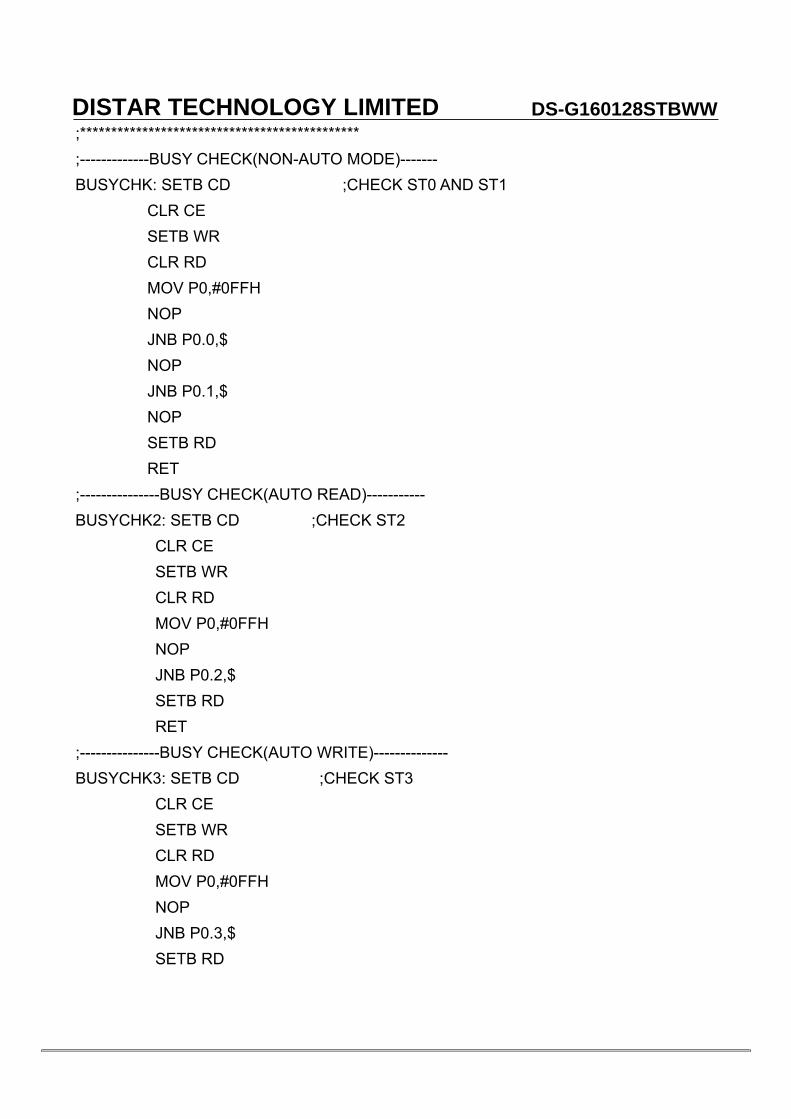
;********************************************* ;-------------BUSY CHECK(NON-AUTO MODE)------- BUSYCHK: SETB CD ;CHECK ST0 AND ST1 CLR CE SETB WR CLR RD MOV P0,#0FFH NOP JNB P0.0,$ NOP JNB P0.1,$ NOP SETB RD RET ;---------------BUSY CHECK(AUTO READ)----------- BUSYCHK2: SETB CD ;CHECK ST2 CLR CE SETB WR CLR RD MOV P0,#0FFH NOP JNB P0.2,$ SETB RD RET ;---------------BUSY CHECK(AUTO WRITE)-------------- BUSYCHK3: SETB CD ;CHECK ST3 CLR CE SETB WR CLR RD MOV P0,#0FFH NOP JNB P0.3,$ SETB RD
DISTAR TECHNOLOGY LIMITED DS-G160128STBWW

RET ;-------------WRITE DATA------------------------ WRDAT: CLR CD ;WRITE DAT TO DATA STACK CLR CE SETB RD MOV P0,DAT CLR WR NOP SETB WR RET ;--------------READ DATA------------------------ RDDAT: CLR CD ;READ DATA FROM DATA STACK CLR CE MOV P0,#0FFH SETB WR CLR RD MOV DAT_R,P0 SETB RD RET ;--------------WRITE COMMAND-------------------- WRCOM: ACALL BUSYCHK ;WRITE COMMAND: COM--COMMAND MOV DAT,CDAT1 ;CDAT1--PARAMETER 1 ACALL WRDAT ;CDAT2--PARAMETER 2 ACALL BUSYCHK MOV DAT,CDAT2 ACALL WRDAT ACALL BUSYCHK SETB CD CLR CE SETB RD MOV P0,COM CLR WR NOP
DISTAR TECHNOLOGY LIMITED DS-G160128STBWW

SETB WR RET ;----------------CLEAR SCREEN--------------- CLRSCR: MOV CDAT1,#00H ;SET D-RAM ADDRESS MOV CDAT2,#00H MOV COM,#24H LCALL WRCOM MOV COM,#0B0H ;SET AUTO-WRITE MODE LCALL WRCOM MOV CLR1,#00H MOV CLR2,#20H MOV DAT,#00H CLS: LCALL BUSYCHK3 LCALL WRDAT DJNZ CLR1,CLS DJNZ CLR2,CLS MOV COM,#0B2H ;END AUTO-WRITE MODE LCALL WRCOM RET ;-------------------DELAY----------------- DELAY: MOV DL1,#02H MOV DL2,#08FH MOV DL3,#0FFH LPDL1: NOP NOP DJNZ DL3,LPDL1 DJNZ DL2,LPDL1 DJNZ DL1,LPDL1 RET ;************************************************** DISP1: DB 088H,088H,022H,022H DB 0FFH,000H,088H,022H END
DISTAR TECHNOLOGY LIMITED DS-G160128STBWW

9. INSPECTION STANDARDS 9.1 Inspection Conditions
The LCD shall be inspected under 40W white fluorescent light. The distance between the eyes and the samples shall be more than 30cm. All directions for inspecting the sample should be within 45 degree against perpendicular line.
9.2 Definition of Applicable Zone
A Zone: Active Display Area
B Zone: Area from Bezel Frame to A Zone C Zone: Rest Area of Bezel A Zone + B Zone=Effective Viewing Area
9.3 Standards NO PARAMETER CRITERIA
1 Black and Round Shape
DISTAR TECHNOLOGY LIMITED DS-G160128STBWW

White Spots, Foreign
Substances
Acceptable Number Zone
DIMENSION(MM) A B C
D≤0.1 * * * 0.1<D≤0.2 5 5 * 0.2<D≤0.3 0 1 *
0.3<D 0 0 * D=(long+short)/2 * Disregard Line Shape
Acceptable Number ZoneX(mm) Y(mm) A B C
- 0.02≥W * * * 2.0≥L 0.03≥W 3 3 * 1.0≥L 0.04≥W 1 2 * 1.0≥L 0.05≥W 0 2 *
- 0.05<W Not acceptable X: Length Y: Width * Disregard Total defects shall not exceed 5.
2 Air Bubbles
(Between glass and polarizer)
Acceptable Number A B C
D≤0.1 * * * 0.1<D≤0.2 5 5 * 0.2<D≤0.3 0 1 *
0.3<D 0 0 * *: Disregard Total defects shall not exceed 3.
3 The Shape of Dot
(1) Dot Shape(with dent)
As per the sketch of left hand. (2) Dot Shape(with Projection)
ZoneDimension(mm)
DISTAR TECHNOLOGY LIMITED DS-G160128STBWW

Should not connect to next dot. (3) Pin Hole
(X+Y)/2<0.2mm (less than 0.1mm is not counted Total defects shall not exceed 5.
4 Polarizer Scratches
Not to be conspicuous defects.
5 Polarizer Dirts If the stains are removed easily from LCD surface,the module is not defective.
6 Color Variation Not to be conspicuous defects. 10. PRECAUTIONS IN USING LCM 1. LIQUID CRYSTAL DISPLAY (LCD) LCD is made up of glass, organic sealant, organic fluid, and polymer based polarizers. The following precautions should be taken when handing, (1). Keep the temperature within range of use and storage. Excessive temperature and humidity could cause polarization degredation, polarizer peel off or bubble. (2). Do not contact the exposed polarizers with anything harder than an HB pencil lead. To clean dust off the display surface. Wipe gently with cotton. Chamois or other soft material soaked in petroleum benzin. (3). Wipe off saliva or water drops immediately. Contact with water over a long period of time may cause polarizer deformation or color fading, while an active LCD with water condensation on its surface will cause corrosion of ITO electrodes. (4). Glass can be easily chipped or cracked from rough handing. especially at corners and edges. (5). Do not drive LCD with DC voltage. 2. Liquid Crystal Display Modules 2.1 Mechanical Considerations LCM are assembled and adjusted with a high degree of precision. Avoid excessive shocks and do not make any alterations or modifications. The following should be noted. (1). Do not tamper in any way with the tabs on the tabs on the metal frame. (2). Do not modify the PCB by drilling extra holes, changing its outline, moving its components or modifying its pattem.
DISTAR TECHNOLOGY LIMITED DS-G160128STBWW

(3). Do not touch the elastomer connector, especially insert an backlight panel (for example, EL). (4). When mounting a LCM make sure that the PCB is not under any tress such as bending or twisting. Elastomer contacts are very delicate and missing pixels could result from slight dislocation of any of the elements. (5). Avoid pressing on the metal bezel, otherwise the elastomer connector could be deformed and lose contact, resulting in missing piels. 2.2. Static Electricity LCM contains CMOS LSI’s and the same precaution for such devices should apply, namely (1). The operator should be grounded whenever he/she comes into contact with the module. Never touch any of the conductive parts such as the LSI pads, the copper leads on the PCB and the interface terminals with any parts of the human body. (2). The modules should be kept in antistatic bags or other containers resistant to static for storage. (3). Only properly grounded soldering irons should be used. (4). If an electric screwdriver is used, it should be well grounded and shielded from commutator sparks. (5). The normal static prevention measures should be observed for work clothes and working benches; for the latter conductive ( rubber) mat is recommended. (6). Since dry air is inductive to statics, a relative humidity of 50-60% is recommended. 2.3. Soldering (1). Solder only to the I/O terminals. (2). Use only soldering irons with proper grounding and no leakage. (3). Soldering temperature: 280 ℃±10℃ (4). Soldering time: 3 to 4 sec. (5). Use eutectic solder with resin flux fill. (6). If flux is used, the LCD surface should be covered to avoid flux spatters. Flux residue should be removed after wards. 2.4. Operation (1). The viewing angle can be adjusted by varying the LCD driving voltage V0. (2). Driving voltage should be kept within specified range; excess voltage shortens display life. (3). Response time increases with decrease in temperature. (4). Display may turn black or dark blue at temperatures above its operational range; this is (however not pressing on the viewing area) may cause the segments to appear “fractured”. (5). Mechanical disturbance during operation (such as pressing on the viewing area) nay cause the segments to appear “fractured”. 2.5. Storage If any fluid leaks out of a damaged glass cell, wash off any human part that comes into contact with soap and water. Never swallow the fluid. The toxicity is extremely low but caution should be exercised at all the time. 2.6. Limited Warranty
Unless otherwise agreed between DISTAR and customer, DISTAR will replace or repair any of its LCD and LC, which is found to be defective electrically and visually when inspected in accordance with DISTAR acceptance standards, for a period on one year fron data of shipment. Confirmation of such date shall be based on freight documents. The warranty
DISTAR TECHNOLOGY LIMITED DS-G160128STBWW

liability of DISTAR is limited to repair and/or replacement on the terms set forth above. DISTAR will not responsible for any subsequent or consequential events.
END
DISTAR TECHNOLOGY LIMITED DS-G160128STBWW