Specifications and Operating Instructions (Med)
56
zebris Medical GmbH REF 79010095 Text-Release: 16/03/21 Specifications and Operating Instructions (Med)
Transcript of Specifications and Operating Instructions (Med)

zebris Medical GmbH REF 79010095 Text-Release: 16/03/21
Specifications and
Operating Instructions (Med)
zebris Medical GmbH FDM-T Technical Specifications and User Manual Page 2/56
Content
1 INTRODUCTION ............................................................................................................................. 4 1.1 MANUFACTURER INFORMATION ...................................................................................................... 4 1.2 STRUCTURE OF THE FDM-T SYSTEM USER MANUAL ........................................................................ 5 1.3 CONVENTIONS AND SYMBOLS USED ............................................................................................... 6
2 APPLICATION AND SAFETY ........................................................................................................ 7 2.1 INTENDED USE .............................................................................................................................. 7 2.1.1 INDICATIONS ................................................................................................................................. 7 2.1.2 CONTRAINDICATIONS ..................................................................................................................... 7 2.2 SAFETY ......................................................................................................................................... 8 2.2.1 ENVIRONMENTAL CONDITIONS ........................................................................................................ 8 2.2.2 STORAGE AND TRANSPORT ............................................................................................................ 8 2.2.3 USER OBLIGATIONS ....................................................................................................................... 9 2.2.4 GENERAL SAFETY INSTRUCTIONS................................................................................................. 10 2.2.5 SAFETY INSTRUCTIONS FOR THE TREADMILL ................................................................................. 11 2.2.6 PROHIBITED USE ......................................................................................................................... 12
3 PRODUCT DESCRIPTION ........................................................................................................... 13 3.1 SYSTEM COMPONENTS ................................................................................................................ 13 3.2 SPECIFICATIONS FDM-T SENSOR ................................................................................................ 13 3.3 TECHNICAL SPECIFICATIONS FDM-T MEASURING SYSTEMS ........................................................... 13 3.4 MEASURING PRINCIPLE FDM-T SYSTEMS .................................................................................... 19 3.5 CONTROLS AND CONNECTORS ..................................................................................................... 20 3.6 LED INDICATOR LIGHTS OF THE INTERFACE BOX ............................................................................ 20 3.7 ZEBRIS SYNC ............................................................................................................................. 21 3.7.1 SYNCHRONIZATION INPUT (SYNC-IN) .......................................................................................... 22 3.7.2 SYNCHRONIZATION OUTPUT (SYNC-OUT) .................................................................................. 23 3.8 SPARE PARTS FDM-T SYSTEM .................................................................................................... 24 3.9 OPTIONS FDM-T MEASURING SYSTEM ........................................................................................ 25
4 VIDEO-MODULE........................................................................................................................... 27 4.1 CONECTION TO THE FDM-T SYSTEM ............................................................................................ 27 4.1.1 CONNECTION TO THE ZEBRIS SYNCCAM ...................................................................................... 27 4.1.2 CONNCECTION SCHEME SYNCLIGHTCAM .................................................................................... 28 4.2 SYNCCAM ................................................................................................................................. 29 4.3 SYNCCAM HS ........................................................................................................................... 30 4.4 SYNCLIGHTCAM – VARIANT 30 HZ .............................................................................................. 32
5 GAIT TRAINING MODULE ........................................................................................................... 35 5.1 GAIT TRAINING TYPE M/L/PL (H/P/COSMOS MERCURY, LOCOMOTION, PLUTO) ................................ 36 5.2 GAIT TRAINING TYPE Q/P/XL AND (H/P/COSMOS QUASAR, PULSAR, LOCOMOTION XL) .................... 37
6 SETUP AND OPERATION OF THE FDM-T SYSTEM ................................................................. 38 6.1 POSITIONING OF THE MEASURING SYSTEM .................................................................................... 38 6.2 INSTALLATION OF THE DETACHABLE CABLE GUARD ........................................................................ 39 6.3 CONNECTION OF THE MEASURING SYSTEM TO MAINS SUPPLY ......................................................... 40 6.3.1 POWER SUPPLY OF THE FDM-T SENSORS .................................................................................... 40 6.3.2 CONNECTION OF THE SYSTEM ...................................................................................................... 41 6.4 IT SECURITY AND SOFTWARE INSTALLATION .................................................................................. 42 6.5 HOW TO SWITCH THE FDM-T SENSOR ON/OFF ............................................................................. 43 6.6 SETTING THE SYSTEM OUT OF OPERATION .................................................................................... 43 6.7 RECOMMENDATIONS FOR RECORDING .......................................................................................... 44 6.7.1 TREADMILL ANALYSIS .................................................................................................................. 44 6.7.2 DATA RECORDING ....................................................................................................................... 44 6.7.3 WALKING SPEED ......................................................................................................................... 44 6.7.4 POSTURE .................................................................................................................................... 44 6.7.5 WEALS........................................................................................................................................ 44
7 MAINTENANCE AND SAFETY INSPECTIONS ......................................................................... 45 7.1 GENERAL MAINTENANCE PROCEDURES ........................................................................................ 45 7.2 MANDATORY PERIODIC INSPECTIONS AND STK ............................................................................ 46 7.3 MAINTENANCE OF THE FDM-T SENSOR ........................................................................................ 47

zebris Medical GmbH FDM-T Technical Specifications and User Manual Page 3/56
7.3.1 CONTROL PROCEDURES .............................................................................................................. 47 7.3.2 CALIBRATION PROCEDURES ......................................................................................................... 47 7.4 TROUBLESHOOTING ..................................................................................................................... 48 7.5 CLEANING AND DISINFECTION ....................................................................................................... 49 7.5.1 CLEANING PROCEDURE ............................................................................................................... 49 7.5.2 DISINFECTION PROCEDURE .......................................................................................................... 49 7.6 DISPOSAL ................................................................................................................................... 50 7.6.1 PACKAGING ................................................................................................................................. 50 7.6.2 WEEE-DIRECTIVE ...................................................................................................................... 50 7.6.3 ACCUMULATORS AND BATTERIES .................................................................................................. 50
8 SAFETY STANDARDS AND CLASSIFICATION OF THE SYSTEM .......................................... 51 8.1 CLASSIFICATION ACC. TO ANNEX IX OF DIRECTIVE 93/42/EEC ...................................................... 51 8.2 SAFETY OF MEDICAL ELECTRICAL DEVICE ...................................................................................... 51 8.2.1 COUPLING OF THE FDM-T MEASURING SYSTEM WITH OTHER ELECTRICAL DEVICES ......................... 51 8.2.2 VICINITY OF THE PATIENT / TEST PERSON ...................................................................................... 52 8.2.3 USE OF MULTIPLE SOCKETS ......................................................................................................... 53 8.3 ELECTROMAGNETIC COMPATIBILITY / MANUFACTURER'S DECLARATION ......................................... 54
zebris Medical GmbH FDM-T Technical Specifications and User Manual Page 4/56
1 Introduction
© 2021 zebris Medical GmbH
All rights reserved. Reproduction in whole or in part only with the express permission of zebris Medical GmbH.
Illustrations of this manual may differ.
1.1 Manufacturer Information
Manufacturer
zebris Medical GmbH Phone +49 (0)7562 9726 - 0
Am Galgenbühl 14 Fax +49 (0)7562 9726 - 50
88316 Isny im Allgäu E-Mail [email protected]
Germany Web www.zebris.de
Sales / Support
zebris Medical GmbH Phone +49 (0)7562 9726 - 300
Am Galgenbühl 14 Fax +49 (0)7562 9726 - 50
88316 Isny im Allgäu E-Mail [email protected]
Germany Web www.zebris.de
Please always provide the serial number of the product for inquiries!

zebris Medical GmbH FDM-T Technical Specifications and User Manual Page 5/56
1.2 Structure of the FDM-T System user manual
The FDM-T measuring system consists of a treadmill, the pressure distribution measuring sensors, and the corresponding application software, including the PC. The sensors and treadmill can also be used completely independently of each other and feature a separate power supply and CE mark.
The user manual for the FDM-T measuring system therefore consists of several sections:
1. FDM-T specifications and hardware user manual
2. zebris FDM user manual for the application software
3. Specifications and user manual supplied by the treadmill manufacturer.
4. User manual and specifications of components like projector or PC
NOTE
Please also be sure to adhere to the user manuals supplied by manufacturers of the treadmill and the components when set-ting the system into operation, while using it, maintaining it, and transporting it.
The section FDM-T specifications and hardware user manual mainly contains information regarding the specifications and operation of the FDM-T pressure distribution measuring sensors and their safe operation in combination with the treadmill, as a measuring system. Instructions regarding the treadmill are restricted to the main safety and servicing measures.
The software and hardware operating instructions can be displayed in the software as online help (F1 key).
In addition, the documents are available on the enclosed installation data carrier and on-line at https://www.zebris.de/en/info-menu/downloads/
WARNING
Read these instructions carefully before using the product for the first time to avoid operating errors and damage.
The exact adherence to all part of the operating Instructions for the measuring system is a precondition for its intended use.

zebris Medical GmbH FDM-T Technical Specifications and User Manual Page 6/56
1.3 Conventions and Symbols Used
The green markings in the margin of the user manual denote new information about the product safety.
“WARNING” symbols indicate a potential hazard to the health and safety of the users and/or patients. The warnings describe the risks involved and those that can be avoided.
Note symbols indicate a potential hazard that can result in dam-age of the device. The notes explain the type of hazard and how it can be prevented.
CE mark according to EC directive 93/42 Medical devices
Manufacturer
Manufacturing Date
Device of type BF according to DIN EN 60601-1
Direct Current
USB-Interface
Do not dispose of with household waste
Refer to instructions for use.
Item Number
Serial Number
Medical Device
zebris Medical GmbH FDM-T Technical Specifications and User Manual Page 7/56
2 Application and safety
2.1 Intended Use
Main function of the pressure distribution measurement system FDM-T is the spatially re-solved pressure distribution measurement under human feet for the analysis of static and dynamic strains as well as the individual gait parameters.
Operation as well as data evaluation and storage are software-aided by using a computer. The measuring systems are suitable for the use with patients that are mentally capable of following the operator’s instructions without limitations in the period of application.
The patient’s weight is limited by the maximum permissible weight of the treadmill. For the application of the FDM-T with children or patients with severe movement disorders, a fall stop safety is strongly recommended.
Professional facilities (medical practices, clinics, scientific institutions, rehabilitation centres, and orthopaedic specialist shops) are specified as application environment.
The application and operation of the system may only be carried out by thoroughly trained qualified personnel such as clinical doctors, physiotherapists, orthopaedic technicians which possess the ability to evaluate the output data in medical aspects as a aid for the diagnosis, treatment or patient care and taking into account the clinical history of the patient in the context of other diagnostic tests.
2.1.1 Indications
• Stance and gait analysis of the “normal” as well as the pathological stance and gait
• Diagnosis support with foot malpositions and foot corrections
• Diagnosis support and therapy of imbalances / incorrect gait pattern
• Detection of inappropriate mechanical stress and overstraining for the prevention of phys-ical problems and for rehabilitation with disabilities after injury, accidents or surgeries.
• Support with the development, adjustment, and verification of orthopaedic aids for the individual patient care
• Balance analysis and balance training
• Gait training in combination with dynamic visual stimulation (cueing) and feedback train-ing as therapy/rehabilitation measures after a surgery, stroke, with the Parkinson’s dis-ease as well as other neurologic geriatric and orthopaedic disorders
• Success control of therapy/rehabilitation measures
2.1.2 Contraindications
• The FDM-T system must not be applied for a barefoot measurement with patients having open wounds and/or infections on the feet.
• Use for gait training with patients having the following contraindications only after ap-proval through a medical specialist: pregnancy, heart and/or arterial diseases, artificial joints or prosthesis, fractures, damaged discs or traumatic disease of the spine.

zebris Medical GmbH FDM-T Technical Specifications and User Manual Page 8/56
2.2 Safety
2.2.1 Environmental conditions
FDM-T measuring systems are suitable for application in dry interiors with level ground such as those in hospitals, doctors' surgeries, and laboratories.
Temperature 10°C to 40°C
Relative humidity 30% to 70%, non-condensing
Air pressure 700 to 1100 hPa
WARNING
FDM-T systems must NOT be operated in wet zones, wet rooms (swimming pools, saunas) or climatic chambers.
Direct contact with liquids must always be avoided, as the measuring system is not protected against the entry of liquids. Liquids penetrat-ing the device can cause fire, electrical shock, or other severe acci-dents.
The FDM-T system is NOT specified for the operation in vacuum, hyperbaric or altitude chambers.
The measuring systems are not intended for operation in potentially explosive atmospheres of medically used rooms or oxygen-enriched atmospheres.
The devices must not be operated in proximity to e.g., engines or transformers with a high connected load as well as mains current lines, as electrical or magnetic interference fields can falsify correct measurements resp. turn them impossible. Therefore, the devices must be protected against humidity. The ventilation slots of the tread-mills must be always free, so that air can circulate freely.
2.2.2 Storage and Transport
Storage and transport of the measuring system are only to be affected in the original pack-aging provided by zebris.
Temperature -20°C to +70°C
Relative humidity max. 95%, non-condensing
Protect from moisture
NOTE
All FDM-T systems can be stored without power supply for a maxi-mum of 6 to 9 months. After this period, the battery may be totally discharged due to lacking power supply. If the storage of the device exceeds this period, a re-programming of the treadmill control may be necessary.
zebris Medical GmbH FDM-T Technical Specifications and User Manual Page 9/56
2.2.3 User Obligations
• The relevant, general guidelines and/or national laws, national regulations and technical rules for the commissioning and the operation of medical products must be applied and fulfilled corresponding to the indicated purpose of the zebris product. In Germany, oper-ators, device in-charge persons and users are obliged to operate their devices in consid-eration of the MPG-regulations.
• Users are obliged to:
✓ observe all safety guidelines of the user manual.
✓ carry out any inspection and maintenance work on a regular basis as stipulated in the user manual.
✓ only use work equipment that is free of defects.
✓ check the functional safety and the proper condition of the device before operating.
✓ make all user manuals that are always accessible to all users and keep the manuals in close proximity of the measuring system.
✓ protect him-/herself, the patient or third parties against dangers.
✓ avoid a contamination through the product.
• When using the system, national legal regulations must be observed, in particular:
✓ the valid industrial safety regulations.
✓ the valid accident prevention measures.
• For the safety, reliability and performance of the components delivered by zebris, respon-sibility is assumed, if:
✓ assembly, extensions, re-settings, changes, or repairs were carried out through zebris or third parties authorised by zebris, trained technicians or employees of au-thorised dealers. Storage and transport are only to be affected in the original pack-aging delivered by the manufacturer.
✓ the device is operated in accordance with the user manual.
✓ in case of repair, the regulations of the VDE 0751-1 “Recurrent test and test before commissioning of medical electrical equipment – general regulations” are fully com-plied with.
✓ the components of information technology provided by the operator correspond to the technical requirements of hard and software included in this user manual and were installed and set up according to the relevant descriptions in this user manual.
✓ the set-up room corresponds to the given environmental conditions of the measuring system and the valid installation regulations.
✓ the FDM-T system including components is connected to the mains socket with a protective grounding conductor and is operated with the correct mains voltage.
✓ exclusively the software provided by zebris as well as the components and accessory parts listed in this user manual are used together with the system.
zebris Medical GmbH FDM-T Technical Specifications and User Manual Page 10/56
2.2.4 General safety instructions
• The application and operation of the system and the evaluation of the measuring data and their interpretation may only be carried out by trained qualified personnel. The man-ufacturer assumes no liability for any injury to persons, damage to property, or loss of data due to improper use of the software, the device or its component parts.
• The patients’ data and measuring data may only be copied, moved, or deleted using the database function provided by the zebris application programs. In the case of data being changed intentionally without using the database functions, the user alone bears the full risks involved.
• Measurement and analysis results should always be interpreted in the light of the clinical history of the patient and in the context of other diagnostic tests by a trained person proven and tested for their relevance.
• Should any measures for treatment be taken based on the measuring results, the meas-uring system may only be implemented as a supplementary means for evaluation by an expert. On no account can, or may invasively measures, or measures endangering the patient be carried out solely based on the measuring results without further verification of the measuring data by additional methods.
• Should there be any detectable damage to the device or component parts, they should be returned to the manufacturer for a safety check. It is not permissible to continue using the device or its component parts, as severe damage, and serious injuries – even lethal injuries - may result. The manufacturer or authorized sales partner must always be con-tacted in all cases of fault or doubt.
• If any fluids should penetrate the device, it is mandatory for the device to undergo a tech-nical, safety test. Damaged plug connections and leads are to be replaced by an author-ized service technician. The device must be put out of operation immediately, marked as "Not working“ and prevented from being used by removing the mains cable. Please refer to an authorized technician immediately.
• The measuring system must be checked for a proper measuring function on a regular basis. Please find more detailed information in chapter 7 of this user manual.
• Be sure that all the mains and connection cables are laid safely and that they are pro-tected against stepping on, so that nobody can trip over them. Check all the cables and the connection plug regularly for any damage. Damaged power supplies and cables must be replaced before further operation.
• Never insert any objects in the components of the measuring system.
zebris Medical GmbH FDM-T Technical Specifications and User Manual Page 11/56
2.2.5 Safety instructions for the Treadmill
• The treadmill belonging to the FDM-T measuring system is a very powerful device. For safe operation of the FDM-T system it is mandatory to adhere exactly to the safety regu-lations described in the following.
• The measuring procedure on the treadmill must never be commenced without a thorough instruction of the patient by trained personnel. No measurements may be taken without a supervisor.
• Do not place the treadmill on an unstable ground.
• Do not set up the system near a source of heating or in direct sunlight in front of a window as a strong rise in temperature can lead to inaccurate measuring results.
• Directly behind the treadmill it is mandatory for a safety zone of 2 m in length and 1 m in width to be kept free, and ought to be padded (with a soft mat). No items may be left in this zone during operation (such as video camera, lighting equipment etc.).
• Dangerous drawing-in gaps are located at the rear end of the running belt and along its sides and (if existing) on the elevating mechanism. Do not wear any loose clothing that could get caught up in the rollers. Make sure that if a person trips over, their long hair, loose clothing, jewellery, etc., do not encounter the rear part of the treadmill belt (e.g., wear a hair net). Due to danger of stumbling, do not place any clothing or jewellery on or within close proximity of the treadmill.
• Never use the treadmill without the safety clip being fastened to your clothing and always be sure that the folding mechanism (if existing) is properly locked during operation. (Please also be sure to read the safety instructions in the user manual supplied by the treadmill manufacturer.)
• During operation, the Emergency STOP facilities must always be within easy reach for the user and the operating personnel.
• The patient should walk slowly to begin with. Then gradually speed can be increased after a few minutes, depending on the patient’s physical condition. Improper or excessive strain through tests resp. measurements can have harmful effects on health.
• Never jump onto the running belt and never jump off it whilst it is running. Never stop walking while the treadmill is running, never turn round or step sideward or backwards. Should movement patterns of this kind be necessary for your measurements, please make sure to use a type of treadmill with a safety arch, protection against falling and a “fall stop” chest belt.
• Pull out the power plug before transporting the treadmill.

zebris Medical GmbH FDM-T Technical Specifications and User Manual Page 12/56
2.2.6 Prohibited Use
• Improper and/or prohibited use of the measuring system is impermissible and zebris warn explicitly against all prohibitions included in this section.
• Do not try to service the treadmill in any manner other than that described in this user manual. By the removal of the protective covers, it is possible that you could expose yourself to lethal high voltages or other hazards.
• We also point out that if any changes are made to this certified device or its components without the prior written consent of zebris, your legal right to operate the device will be void. If changes are made to the device without obtaining approval, the operator is obli-gated to carry out suitable investigations and tests in order to guarantee safe use.
• It is prohibited to embed the treadmill in the floor to reduce (track) access height. This way of installation might create a highly dangerous capture area at the rear guide pulley of the treadmill. The zebris Medical GmbH expressively will undertake no liability for inju-ries to any person when the treadmill is operated under such condition!
• All applications using wheels are prohibited (cycling, wheelchair, inline skating or roll ski) as well as running shoes with spikes or studs. Besides their extremely high risk of injury, these can cause irreparable damage to the sensors.
• There should never be more than one person on the treadmill at a time once it is in oper-ation.
• Children and animals are not allowed to use the treadmill without supervision and must maintain a safety distance of at least 5 m.
• Any manner of over-exerting the test persons is strictly prohibited. In cases of nausea and dizziness, the measuring is to be discontinued immediately and a doctor consulted.
• Any form of operation involving an increased hazard is strictly prohibited, e.g., sprinting, or also using test persons having an increased risk.
• The use of the measuring system under the influence of alcohol, drugs or narcotics is strictly prohibited.
• zebris measuring systems may not be operated in any other environmental conditions than those listed in the section "Specifications", (e.g., in wet zones, moisture-prone areas, or in climatic, vacuum, hyperbaric or decompression chambers, etc.). Direct contact with liquids must always be avoided, as the measuring system is not protected against enter-ing liquids. Liquids entering the device can cause fire, electric shock, or other severe accidents.
zebris Medical GmbH FDM-T Technical Specifications and User Manual Page 13/56
3 Product description
3.1 System Components
In its basic configuration the measuring system consists of the following components:
• Treadmill with integrated sensor equipment for measuring the pressure distribution.
• Safety clip for the emergency shutdown
• Mains cable for connecting the treadmill.
• External power supply unit for the FDM-T pressure plate
• USB cable (Type A-B, 3 m long)
• zebris application software zebris FDM
• Windows-compatible computer or notebook
• Silicone oil for lubricating the belt.
• Cable guard with screws
• User manual for FDM-T system, treadmill, zebris FDM software
3.2 Specifications FDM-T Sensor
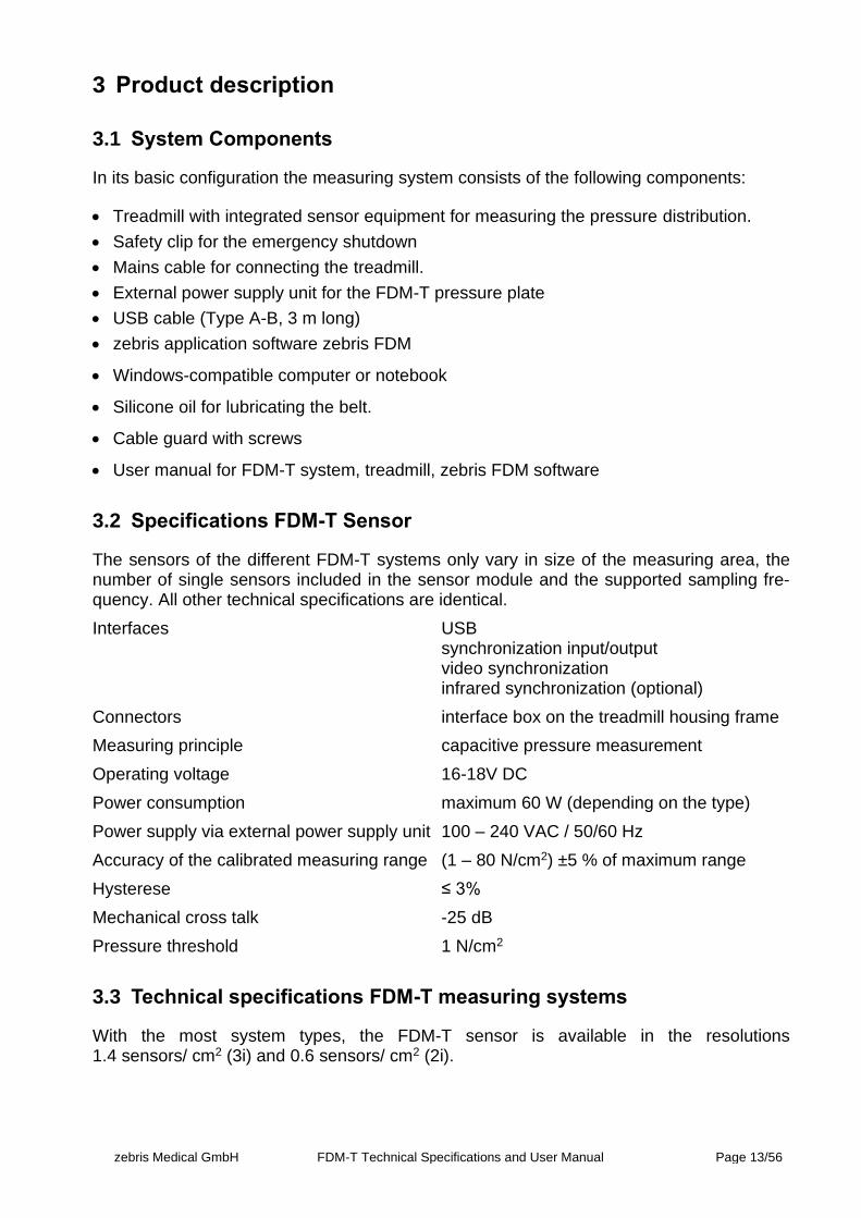
The sensors of the different FDM-T systems only vary in size of the measuring area, the number of single sensors included in the sensor module and the supported sampling fre-quency. All other technical specifications are identical.
Interfaces USB synchronization input/output video synchronization infrared synchronization (optional)
Connectors interface box on the treadmill housing frame
Measuring principle capacitive pressure measurement
Operating voltage 16-18V DC
Power consumption maximum 60 W (depending on the type)
Power supply via external power supply unit 100 – 240 VAC / 50/60 Hz
Accuracy of the calibrated measuring range (1 – 80 N/cm2) ±5 % of maximum range
Hysterese ≤ 3%
Mechanical cross talk -25 dB
Pressure threshold 1 N/cm2
3.3 Technical specifications FDM-T measuring systems
With the most system types, the FDM-T sensor is available in the resolutions 1.4 sensors/ cm2 (3i) and 0.6 sensors/ cm2 (2i).
zebris Medical GmbH FDM-T Technical Specifications and User Manual Page 14/56
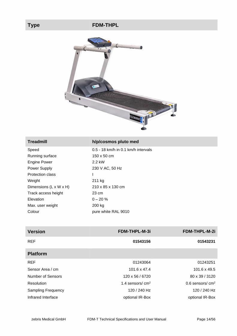
Type FDM-THPL
Treadmill h/p/cosmos pluto med
Speed 0.5 - 18 km/h in 0.1 km/h intervals
Running surface 150 x 50 cm
Engine Power 2.2 kW
Power Supply 230 V AC, 50 Hz
Protection class I
Weight 211 kg
Dimensions (L x W x H) 210 x 85 x 130 cm
Track access height 23 cm
Elevation 0 – 20 %
Max. user weight 200 kg
Colour pure white RAL 9010
Version FDM-THPL-M-3i FDM-THPL-M-2i
REF 01543156 01543231
Platform
REF 01243064 01243251
Sensor Area / cm 101.6 x 47.4 101.6 x 49.5
Number of Sensors 120 x 56 / 6720 80 x 39 / 3120
Resolution 1.4 sensors/ cm2 0.6 sensors/ cm2
Sampling Frequency 120 / 240 Hz 120 / 240 Hz
Infrared Interface optional IR-Box optional IR-Box
zebris Medical GmbH FDM-T Technical Specifications and User Manual Page 15/56
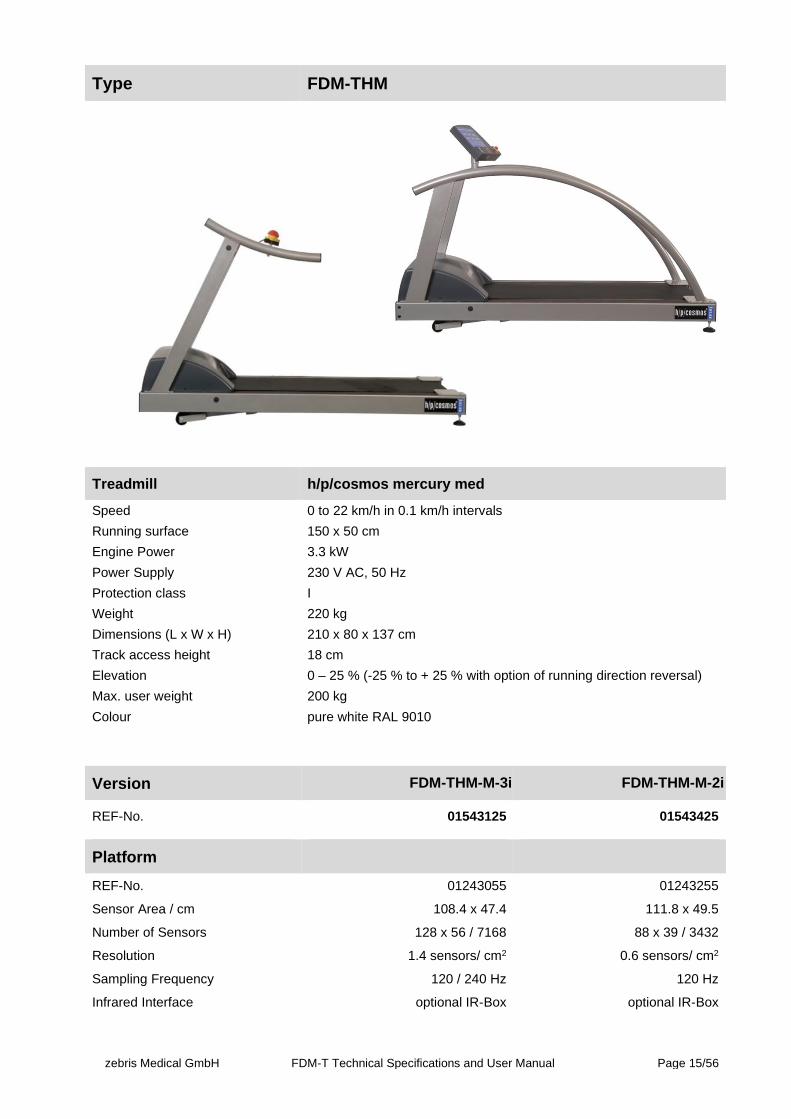
Type FDM-THM
Treadmill h/p/cosmos mercury med
Speed 0 to 22 km/h in 0.1 km/h intervals
Running surface 150 x 50 cm
Engine Power 3.3 kW
Power Supply 230 V AC, 50 Hz
Protection class I
Weight 220 kg
Dimensions (L x W x H) 210 x 80 x 137 cm
Track access height 18 cm
Elevation 0 – 25 % (-25 % to + 25 % with option of running direction reversal)
Max. user weight 200 kg
Colour pure white RAL 9010
Version FDM-THM-M-3i FDM-THM-M-2i
REF-No. 01543125 01543425
Platform
REF-No. 01243055 01243255
Sensor Area / cm 108.4 x 47.4 111.8 x 49.5
Number of Sensors 128 x 56 / 7168 88 x 39 / 3432
Resolution 1.4 sensors/ cm2 0.6 sensors/ cm2
Sampling Frequency 120 / 240 Hz 120 Hz
Infrared Interface optional IR-Box optional IR-Box
zebris Medical GmbH FDM-T Technical Specifications and User Manual Page 16/56
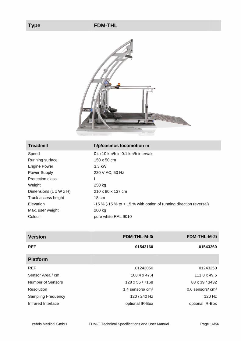
Type FDM-THL
Treadmill h/p/cosmos locomotion m
Speed 0 to 10 km/h in 0.1 km/h intervals
Running surface 150 x 50 cm
Engine Power 3.3 kW
Power Supply 230 V AC, 50 Hz
Protection class I
Weight 250 kg
Dimensions (L x W x H) 210 x 80 x 137 cm
Track access height 18 cm
Elevation -15 % (-15 % to + 15 % with option of running direction reversal)
Max. user weight 200 kg
Colour pure white RAL 9010
Version FDM-THL-M-3i FDM-THL-M-2i
REF 01543160 01543260
Platform
REF 01243050 01243250
Sensor Area / cm 108.4 x 47.4 111.8 x 49.5
Number of Sensors 128 x 56 / 7168 88 x 39 / 3432
Resolution 1.4 sensors/ cm2 0.6 sensors/ cm2
Sampling Frequency 120 / 240 Hz 120 Hz
Infrared Interface optional IR-Box optional IR-Box
zebris Medical GmbH FDM-T Technical Specifications and User Manual Page 17/56
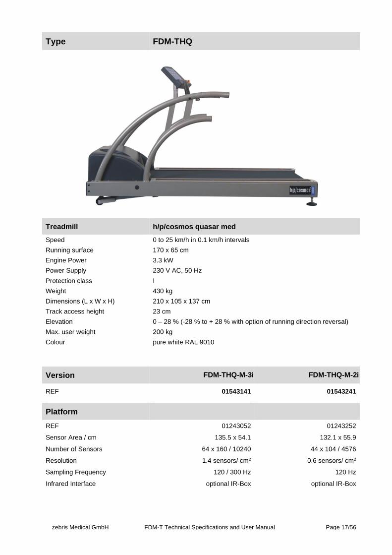
Type FDM-THQ
Treadmill h/p/cosmos quasar med
Speed 0 to 25 km/h in 0.1 km/h intervals
Running surface 170 x 65 cm
Engine Power 3.3 kW
Power Supply 230 V AC, 50 Hz
Protection class I
Weight 430 kg
Dimensions (L x W x H) 210 x 105 x 137 cm
Track access height 23 cm
Elevation 0 – 28 % (-28 % to + 28 % with option of running direction reversal)
Max. user weight 200 kg
Colour pure white RAL 9010
Version FDM-THQ-M-3i FDM-THQ-M-2i
REF 01543141 01543241
Platform
REF 01243052 01243252
Sensor Area / cm 135.5 x 54.1 132.1 x 55.9
Number of Sensors 64 x 160 / 10240 44 x 104 / 4576
Resolution 1.4 sensors/ cm2 0.6 sensors/ cm2
Sampling Frequency 120 / 300 Hz 120 Hz
Infrared Interface optional IR-Box optional IR-Box

zebris Medical GmbH FDM-T Technical Specifications and User Manual Page 18/56
Type FDM-THP
Treadmill h/p/cosmos pulsar med
Speed 0 to 40 km/h in 0.1 km/h intervals
Running surface 190 x 65 cm
Engine Power 3.3 kW
Power Supply 230 V AC, 50 Hz
Protection class I
Weight 460 kg
Dimensions (L x W x H) 250 x 105 x 140 cm
Track access height 23 cm
Elevation -25 % to + 25 %
Max. user weight 200 kg
Colour pure white RAL 9010
Version FDM-THP-M-3i FDM-THP-M-2i
REF 01543150 01543250
Platform
REF 01243059 01243253
Sensor Area / cm 155 x 54.1 155 x 54.1
Number of Sensors 192 x 64 / 12288 128 x 44 / 5632
Resolution 1,4 sensors/ cm2 0,6 sensors/ cm2
Sampling Frequency 100 / 200 / 300 Hz 100 / 200 / 300 Hz
Infrared Interface optional IR-Box optional IR-Box
zebris Medical GmbH FDM-T Technical Specifications and User Manual Page 19/56
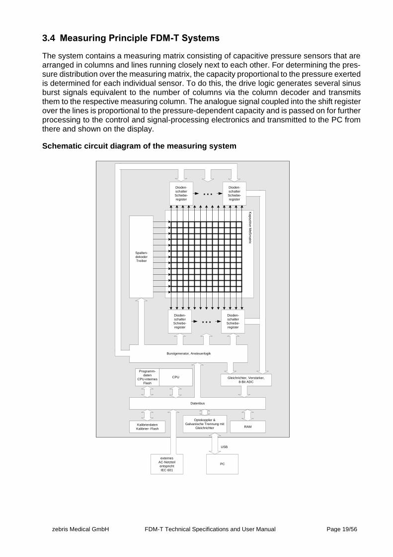
3.4 Measuring Principle FDM-T Systems
The system contains a measuring matrix consisting of capacitive pressure sensors that are arranged in columns and lines running closely next to each other. For determining the pres-sure distribution over the measuring matrix, the capacity proportional to the pressure exerted is determined for each individual sensor. To do this, the drive logic generates several sinus burst signals equivalent to the number of columns via the column decoder and transmits them to the respective measuring column. The analogue signal coupled into the shift register over the lines is proportional to the pressure-dependent capacity and is passed on for further processing to the control and signal-processing electronics and transmitted to the PC from there and shown on the display.
Schematic circuit diagram of the measuring system K
ap
azitiv
e M
eß
ma
trix
Spalten-
dekoder
Treiber
Dioden-
schalter
Schiebe-
register
Dioden-
schalter
Schiebe-
register
...
Burstgenerator, Ansteuerlogik
Gleichrichter, Verstärker,
8-Bit ADC
Datenbus
Kalibrierdaten
Kalibrier- FlashRAM
Optokoppler &
Galvanische Trennung mit
Gleichrichter
PC
externes
AC-Netzteil
entspricht
IEC 601
USB
CPU
Programm-
daten
CPU-internes
Flash
Dioden-
schalter
Schiebe-
register
Dioden-
schalter
Schiebe-
register
...
zebris Medical GmbH FDM-T Technical Specifications and User Manual Page 20/56
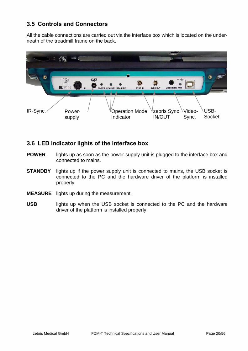
3.5 Controls and Connectors
All the cable connections are carried out via the interface box which is located on the under-neath of the treadmill frame on the back.
3.6 LED indicator lights of the interface box
POWER lights up as soon as the power supply unit is plugged to the interface box and connected to mains.
STANDBY lights up if the power supply unit is connected to mains, the USB socket is connected to the PC and the hardware driver of the platform is installed properly.
MEASURE lights up during the measurement.
USB lights up when the USB socket is connected to the PC and the hardware driver of the platform is installed properly.
USB- Socket
Power-supply
IR-Sync. zebris Sync IN/OUT
Operation Mode Indicator
Video- Sync.

zebris Medical GmbH FDM-T Technical Specifications and User Manual Page 21/56
3.7 zebris SYNC
The zebris SYNC is the standard solution for synchronization of the FDM-T system with third party measuring devices.
The SYNC-IN and SYNC-OUT sockets provide input and output for support of „sample by sample“ In- and Out synchronization. Both sockets provide galvanic protection between third party systems and FDM-T sensor.
WARNING
Patient’s safety is guaranteed by means of galvanic separation ac-cording to the provisions of IEC 601-1 when a third-party device is synchronized with the FDM-T system. This allows non-medical equipment to be synchronized with the FDM-T system if such devices are out of patients reach. Nevertheless, the user is completely re-sponsible for the safety of all third-party devices used in combination with the FDM-T system.
The correct synchronisation of all measurement data must be verified in case devices are connected to zebris SYNC which have not been manufactured by zebris Medical GmbH.
zebris does not accept any liability for correct function and reliability of the system if the clock signal of external devices does not comply with the signal specifications provided with in this user manual.
zebris Medical GmbH FDM-T Technical Specifications and User Manual Page 22/56
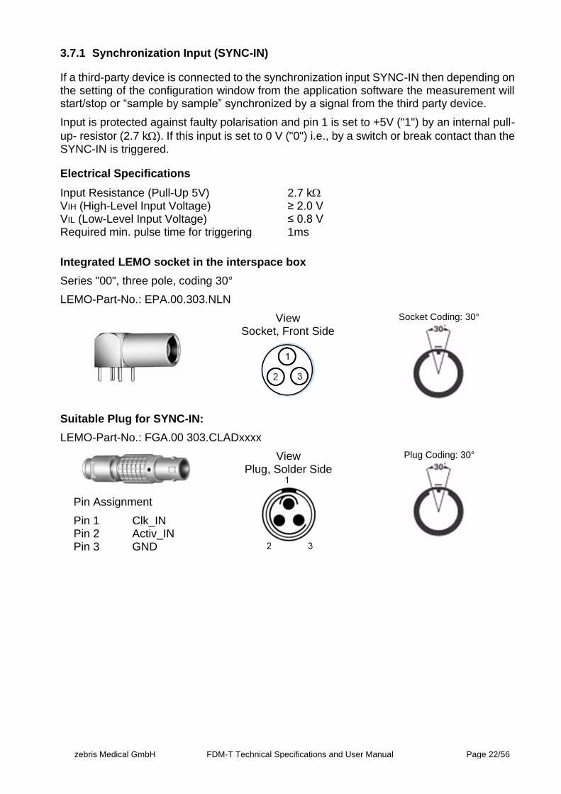
3.7.1 Synchronization Input (SYNC-IN)
If a third-party device is connected to the synchronization input SYNC-IN then depending on the setting of the configuration window from the application software the measurement will start/stop or “sample by sample” synchronized by a signal from the third party device.
Input is protected against faulty polarisation and pin 1 is set to +5V ("1") by an internal pull-
up- resistor (2.7 k). If this input is set to 0 V ("0") i.e., by a switch or break contact than the SYNC-IN is triggered.
Electrical Specifications
Input Resistance (Pull-Up 5V) 2.7 k VIH (High-Level Input Voltage) ≥ 2.0 V VIL (Low-Level Input Voltage) ≤ 0.8 V Required min. pulse time for triggering 1ms
Integrated LEMO socket in the interspace box
Series "00", three pole, coding 30°
LEMO-Part-No.: EPA.00.303.NLN
View Socket, Front Side
Socket Coding: 30°
Suitable Plug for SYNC-IN:
LEMO-Part-No.: FGA.00 303.CLADxxxx
Pin Assignment
Pin 1 Clk_IN Pin 2 Activ_IN Pin 3 GND
View Plug, Solder Side
Plug Coding: 30°
zebris Medical GmbH FDM-T Technical Specifications and User Manual Page 23/56
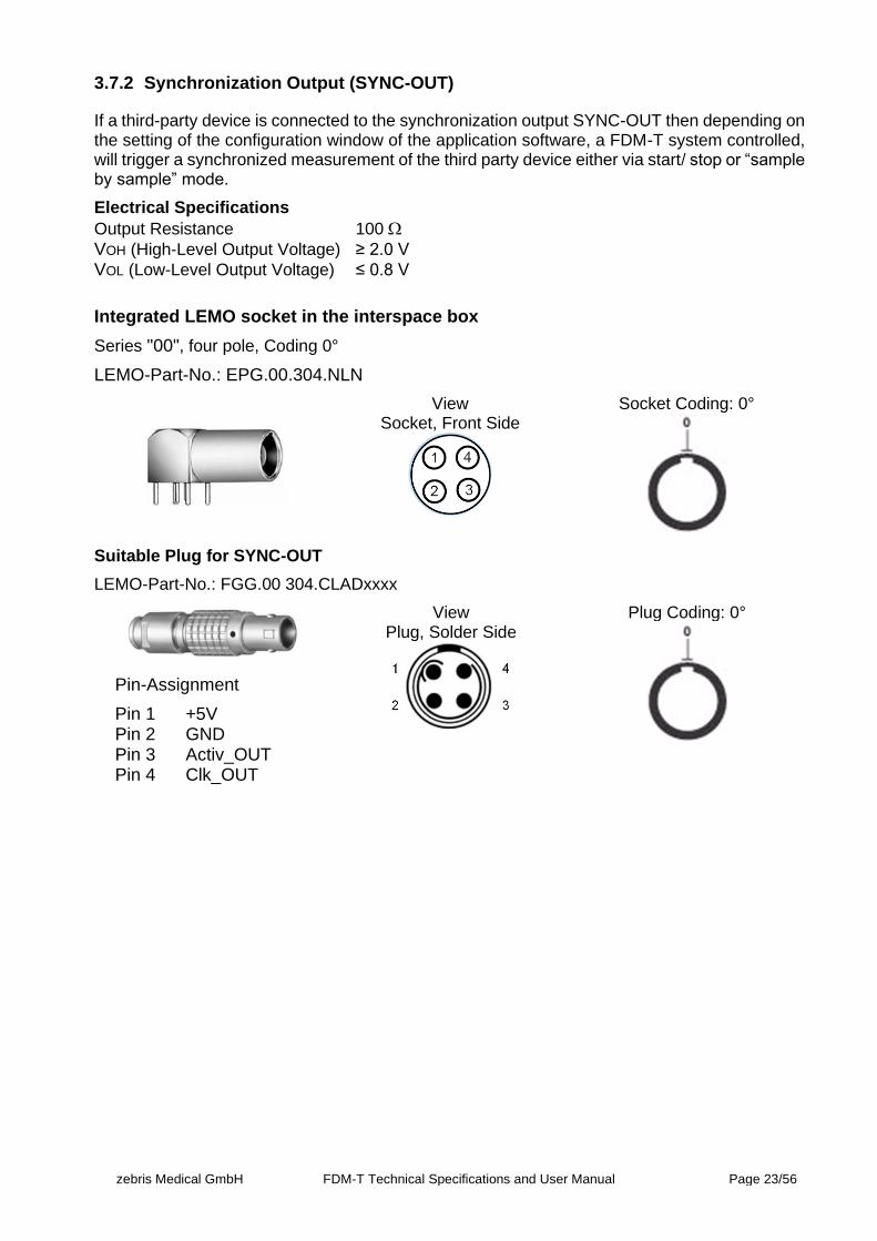
3.7.2 Synchronization Output (SYNC-OUT)
If a third-party device is connected to the synchronization output SYNC-OUT then depending on the setting of the configuration window of the application software, a FDM-T system controlled, will trigger a synchronized measurement of the third party device either via start/ stop or “sample by sample” mode.
Electrical Specifications
Output Resistance 100
VOH (High-Level Output Voltage) ≥ 2.0 V
VOL (Low-Level Output Voltage) ≤ 0.8 V
Integrated LEMO socket in the interspace box
Series "00", four pole, Coding 0°
LEMO-Part-No.: EPG.00.304.NLN
View Socket, Front Side
Socket Coding: 0°
Suitable Plug for SYNC-OUT
LEMO-Part-No.: FGG.00 304.CLADxxxx
Pin-Assignment
Pin 1 +5V Pin 2 GND Pin 3 Activ_OUT Pin 4 Clk_OUT
View Plug, Solder Side
Plug Coding: 0°
zebris Medical GmbH FDM-T Technical Specifications and User Manual Page 24/56
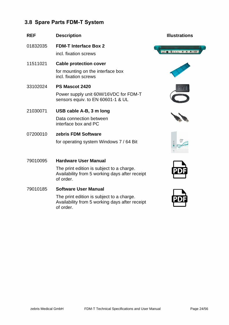
3.8 Spare Parts FDM-T System
REF Description Illustrations
01832035 FDM-T Interface Box 2
incl. fixation screws
11511021 Cable protection cover
for mounting on the interface box incl. fixation screws
33102024 PS Mascot 2420
Power supply unit 60W/16VDC for FDM-T sensors equiv. to EN 60601-1 & UL
21030071 USB cable A-B, 3 m long
Data connection between interface box and PC
07200010 zebris FDM Software
for operating system Windows 7 / 64 Bit
79010095 Hardware User Manual
The print edition is subject to a charge. Availability from 5 working days after receipt of order.
79010185 Software User Manual
The print edition is subject to a charge. Availability from 5 working days after receipt of order.

zebris Medical GmbH FDM-T Technical Specifications and User Manual Page 25/56
3.9 Options FDM-T Measuring System
REF Description Illustrations
01540191 SYNCCam
Camera with USB-Cable, synchronization cable, inclusive software extension
01540192 SYNCCam HS
Camera with USB-Cable, synchronization-cable, removable aperture, synchronisation optionally via cable or infrared, includes soft-ware extension.
01540194 SYNCLightCam – Variant 30 Hz
Combined solution with Camera and illu-minetion, 5 m USB2.0-Cable, synchroniza-tion cable, inclusive software extension.
21030321 SYNCCam/SYNCLightCam 30 Hz USB-Ca-ble A-B
USB2.0-Cable for HD-video signal with high quality plugs, EMC-shielding, and ferrites length 5 m
21030110 USB3.0 fibre optical cable A-male/ A-fe-male
Extension cable beteween USB3.0 cable A-B 1 m and PC length 20 m
21030316 Video Sync-Control Cable 5
Length 5 m, both sides phone jack 3.5 mm
21030312 Video Sync-Control Extension Cable
Length 5 m, phone jack & socket 3.5 mm
zebris Medical GmbH FDM-T Technical Specifications and User Manual Page 26/56
01831105 SYNCLightCam 30Hz Power Supply
Main’s adapter 40 W / 24 V DC
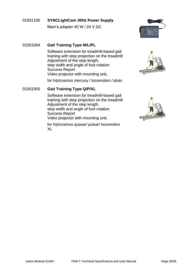
01551004 Gait Training Type M/L/PL
Software extension for treadmill-based gait training with step projection on the treadmill Adjustment of the step length, step width and angle of foot rotation Success Report Video projector with mounting unit,
for h/p/cosmos mercury / locomotion / pluto
01551005 Gait Training Type Q/P/XL
Software extension for treadmill-based gait training with step projection on the treadmill Adjustment of the step length, step width and angle of foot rotation Success Report Video projector with mounting unit,
for h/p/cosmos quasar/ pulsar/ locomotion XL
zebris Medical GmbH FDM-T Technical Specifications and User Manual Page 27/56
4 Video-Module
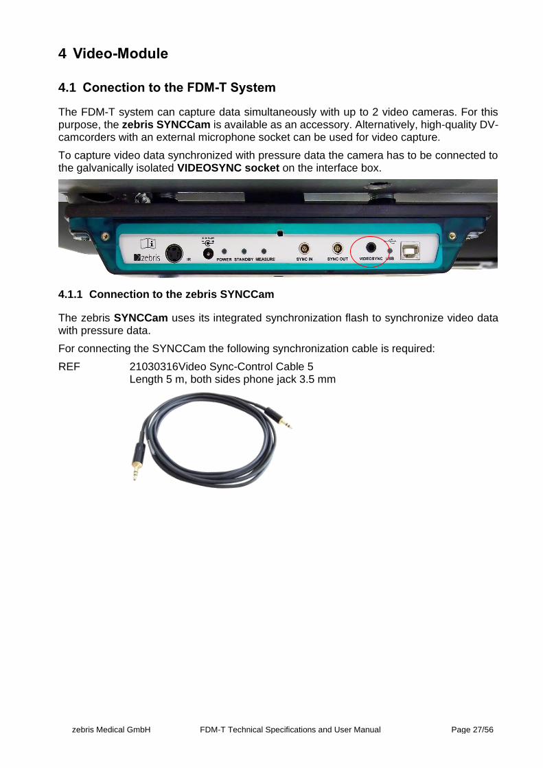
4.1 Conection to the FDM-T System
The FDM-T system can capture data simultaneously with up to 2 video cameras. For this purpose, the zebris SYNCCam is available as an accessory. Alternatively, high-quality DV-camcorders with an external microphone socket can be used for video capture.
To capture video data synchronized with pressure data the camera has to be connected to the galvanically isolated VIDEOSYNC socket on the interface box.
4.1.1 Connection to the zebris SYNCCam
The zebris SYNCCam uses its integrated synchronization flash to synchronize video data with pressure data.
For connecting the SYNCCam the following synchronization cable is required:
REF 21030316Video Sync-Control Cable 5 Length 5 m, both sides phone jack 3.5 mm
zebris Medical GmbH FDM-T Technical Specifications and User Manual Page 28/56
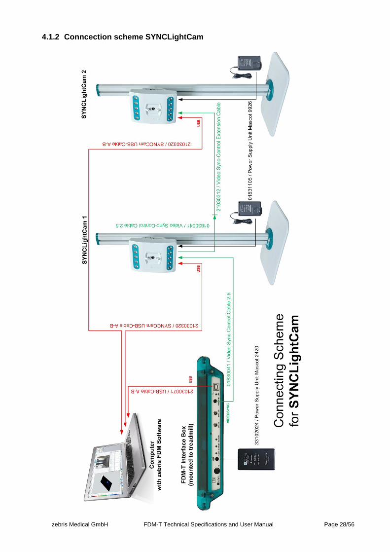
4.1.2 Conncection scheme SYNCLightCam
zebris Medical GmbH FDM-T Technical Specifications and User Manual Page 29/56
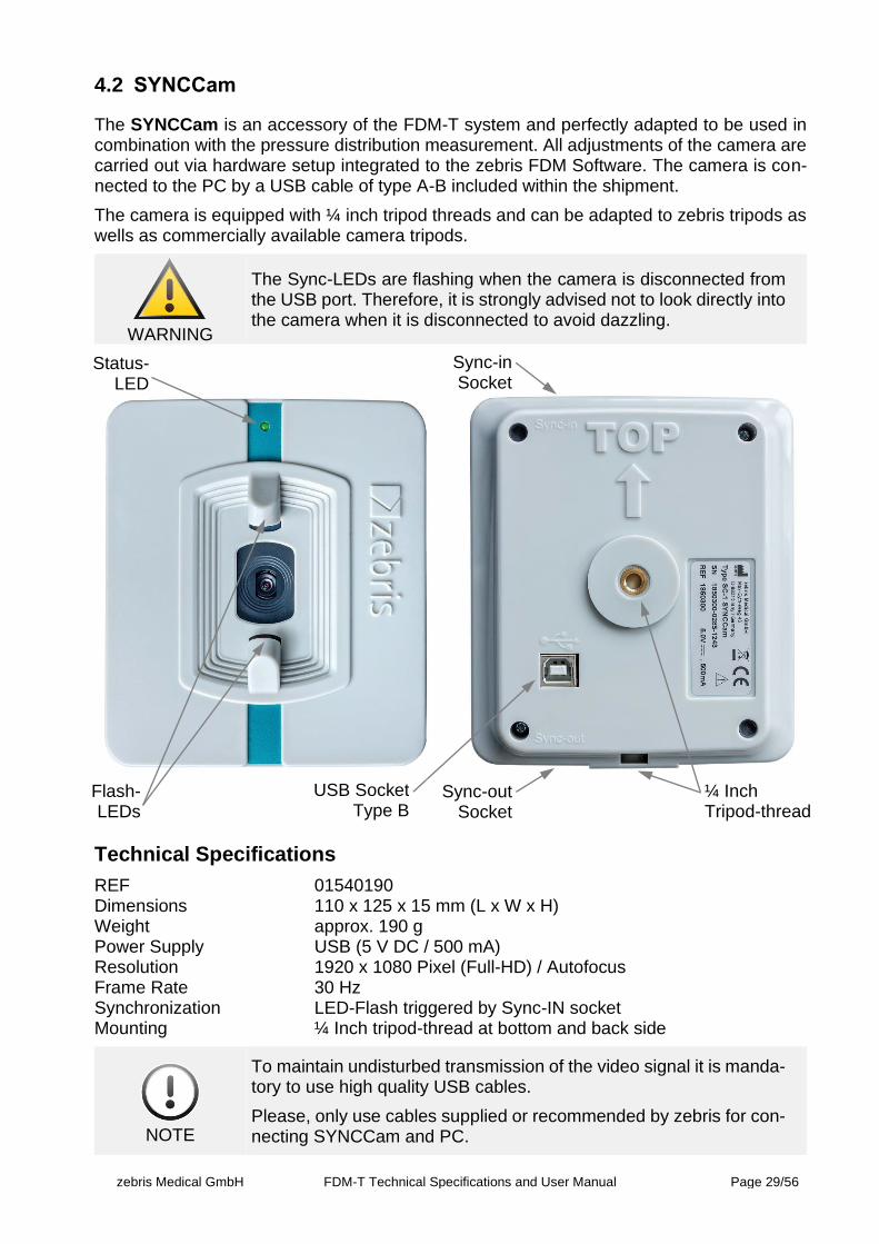
4.2 SYNCCam
The SYNCCam is an accessory of the FDM-T system and perfectly adapted to be used in combination with the pressure distribution measurement. All adjustments of the camera are carried out via hardware setup integrated to the zebris FDM Software. The camera is con-nected to the PC by a USB cable of type A-B included within the shipment.
The camera is equipped with ¼ inch tripod threads and can be adapted to zebris tripods as wells as commercially available camera tripods.
WARNING
The Sync-LEDs are flashing when the camera is disconnected from the USB port. Therefore, it is strongly advised not to look directly into the camera when it is disconnected to avoid dazzling.
Technical Specifications
REF 01540190 Dimensions 110 x 125 x 15 mm (L x W x H) Weight approx. 190 g Power Supply USB (5 V DC / 500 mA) Resolution 1920 x 1080 Pixel (Full-HD) / Autofocus Frame Rate 30 Hz Synchronization LED-Flash triggered by Sync-IN socket Mounting ¼ Inch tripod-thread at bottom and back side
NOTE
To maintain undisturbed transmission of the video signal it is manda-tory to use high quality USB cables.
Please, only use cables supplied or recommended by zebris for con-necting SYNCCam and PC.
Flash-LEDs
Status-LED
USB Socket Type B
Sync-out Socket
Sync-in Socket
¼ Inch Tripod-thread
zebris Medical GmbH FDM-T Technical Specifications and User Manual Page 30/56
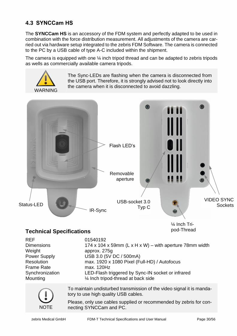
4.3 SYNCCam HS
The SYNCCam HS is an accessory of the FDM system and perfectly adapted to be used in combination with the force distribution measurement. All adjustments of the camera are car-ried out via hardware setup integrated to the zebris FDM Software. The camera is connected to the PC by a USB cable of type A-C included within the shipment.
The camera is equipped with one ¼ inch tripod thread and can be adapted to zebris tripods as wells as commercially available camera tripods.
WARNING
The Sync-LEDs are flashing when the camera is disconnected from the USB port. Therefore, it is strongly advised not to look directly into the camera when it is disconnected to avoid dazzling.
Technical Specifications
REF 01540192 Dimensions 174 x 104 x 59mm (L x H x W) – with aperture 78mm width Weight approx. 275g Power Supply USB 3.0 (5V DC / 500mA) Resolution max. 1920 x 1080 Pixel (Full-HD) / Autofocus Frame Rate max. 120Hz Synchronization LED-Flash triggered by Sync-IN socket or infrared Mounting ¼ Inch tripod-thread at back side
NOTE
To maintain undisturbed transmission of the video signal it is manda-tory to use high quality USB cables.
Please, only use cables supplied or recommended by zebris for con-necting SYNCCam and PC.
USB-socket 3.0 Typ C
Flash LED‘s
Status-LED VIDEO SYNC
Sockets
¼ Inch Tri-pod-Thread
IR-Sync
Removable aperture
zebris Medical GmbH FDM-T Technical Specifications and User Manual Page 31/56
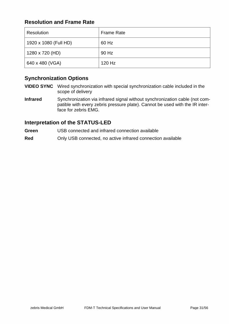
Resolution and Frame Rate
Resolution Frame Rate
1920 x 1080 (Full HD) 60 Hz
1280 x 720 (HD) 90 Hz
640 x 480 (VGA) 120 Hz
Synchronization Options
VIDEO SYNC Wired synchronization with special synchronization cable included in the scope of delivery
Infrared Synchronization via infrared signal without synchronization cable (not com-patible with every zebris pressure plate). Cannot be used with the IR inter-face for zebris EMG.
Interpretation of the STATUS-LED
Green USB connected and infrared connection available
Red Only USB connected, no active infrared connection available

zebris Medical GmbH FDM-T Technical Specifications and User Manual Page 32/56
4.4 SYNCLightCam – Variant 30 Hz
The SYNCLightCam is an accessory of the FDM-T system and perfectly adapted to be used in combination with the pressure distribution measurement. All adjustments of the camera are carried out via hardware setup integrated to the zebris FDM Software. The camera is connected to the PC by a USB cable of type A-B included within the shipment.
The SYNCLightCam is equipped with ¼ inch tripod threads and can be adapted to zebris tripods as wells as commercially available camera tripods.
WARNING
The Sync-LEDs are flashing when the camera is disconnected from the USB port. Therefore, it is strongly advised not to look directly into the camera when it is disconnected to avoid dazzling.
Furthermore, contains the SYNCLightCam as an integral solution, the LED video illumina-tion.
To produce well lighted and tack sharp video captures it is essential to maintain perfect lighting conditions at the patient’s side. Only with adequate lighting conditions video cameras can work with shutter times short enough to freeze fast movements and capture sharp images.
This solution is perfectly matched on the interaction with the FDM-T system and can be regulated infinitely in its brightness.
The integrated synchronization unit automatically switches the lights on at the start of a measurement and turns them off again after stopping it.
NOTE
To ensure failure-free operation of the SYNCLights it is mandatory to keep the black heat sinks at their back side uncovered and well air circulated at all times.
Power-LEDs Heat Sink
¼ Inch Tripod-Thread
Typeplate Flash-LED
zebris Medical GmbH FDM-T Technical Specifications and User Manual Page 33/56
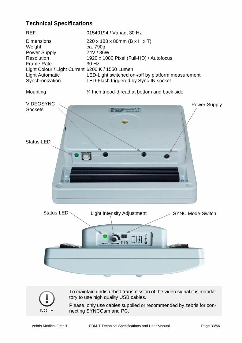
Technical Specifications
REF 01540194 / Variant 30 Hz
Dimensions 220 x 183 x 80mm (B x H x T) Weight ca. 790g Power Supply 24V / 36W Resolution 1920 x 1080 Pixel (Full-HD) / Autofocus Frame Rate 30 Hz Light Colour / Light Current 6200 K / 1550 Lumen Light Automatic LED-Light switched on-/off by platform measurement Synchronization LED-Flash triggered by Sync-IN socket Mounting ¼ Inch tripod-thread at bottom and back side
NOTE
To maintain undisturbed transmission of the video signal it is manda-tory to use high quality USB cables.
Please, only use cables supplied or recommended by zebris for con-necting SYNCCam and PC.
Status-LED Light Intensity Adjustment SYNC Mode-Switch
VIDEOSYNC Sockets
Status-LED
Power-Supply
zebris Medical GmbH FDM-T Technical Specifications and User Manual Page 34/56
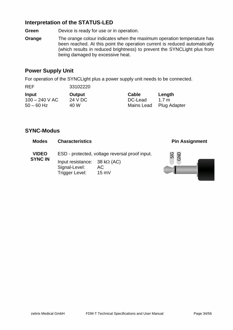
Interpretation of the STATUS-LED
Green Device is ready for use or in operation.
Orange The orange colour indicates when the maximum operation temperature has been reached. At this point the operation current is reduced automatically (which results in reduced brightness) to prevent the SYNCLight plus from being damaged by excessive heat.
Power Supply Unit
For operation of the SYNCLight plus a power supply unit needs to be connected.
REF 33102220
Input Output Cable Length 100 – 240 V AC 24 V DC DC-Lead 1.7 m 50 – 60 Hz 40 W Mains Lead Plug Adapter
SYNC-Modus
Modes Characteristics Pin Assignment
VIDEO SYNC IN
ESD - protected, voltage reversal proof input.
Input resistance: 38 k (AC) Signal-Level: AC Trigger Level: 15 mV

zebris Medical GmbH FDM-T Technical Specifications and User Manual Page 35/56
5 Gait Training Module
For the gait training and the feedback training (virtual Forestwalk) a projector unit can be mounted to the treadmill frame. To accomplish adapters individually engineered for different treadmill types are necessary. The assembly of the available adapter types is described below.
NOTE
For setup, installation and safety related instructions of the projector please refer to the user manual of the projector manufacturer.
The projector is connected directly to the corresponding hardware interface (mostly HMDI). The projection during gait training is controlled by the gait training module of the zebris FDM software.
WARNING
During long periods of operation, the projector can become very hot around the lamp and at the air outlet openings and thus should not be touched.
WARNING
To minimise the risk of falling and to prolong the lifetime of the pro-jection lamp, the projector should only be switched on during the gait training and otherwise be switched off.
WARNING
With treadmills featuring an inverse driving direction, the projector must be separated from the mains before activating the inverse driv-ing direction.
As with installed projector and activated inverse driving direction a higher risk of injury through falling exists because of the projector, a safety (safety bow with chest strap) should always be used with treadmills featuring an inverse driving direction.
zebris Medical GmbH FDM-T Technical Specifications and User Manual Page 36/56
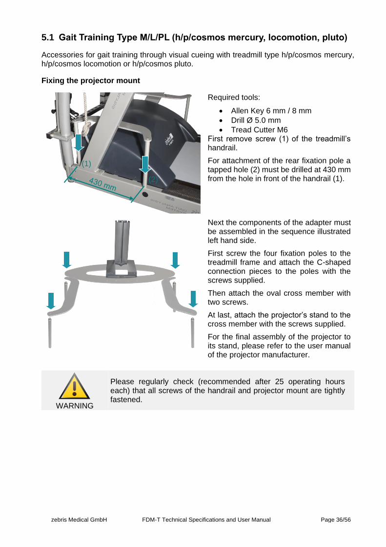
5.1 Gait Training Type M/L/PL (h/p/cosmos mercury, locomotion, pluto)
Accessories for gait training through visual cueing with treadmill type h/p/cosmos mercury, h/p/cosmos locomotion or h/p/cosmos pluto.
Fixing the projector mount
Required tools:
• Allen Key 6 mm / 8 mm
• Drill Ø 5.0 mm
• Tread Cutter M6 First remove screw (1) of the treadmill’s handrail.
For attachment of the rear fixation pole a tapped hole (2) must be drilled at 430 mm from the hole in front of the handrail (1).
Next the components of the adapter must be assembled in the sequence illustrated left hand side.
First screw the four fixation poles to the treadmill frame and attach the C-shaped connection pieces to the poles with the screws supplied.
Then attach the oval cross member with two screws.
At last, attach the projector’s stand to the cross member with the screws supplied.
For the final assembly of the projector to its stand, please refer to the user manual of the projector manufacturer.
WARNING
Please regularly check (recommended after 25 operating hours each) that all screws of the handrail and projector mount are tightly fastened.
(1)
(2)

zebris Medical GmbH FDM-T Technical Specifications and User Manual Page 37/56
5.2 Gait Training Type Q/P/XL and (h/p/cosmos quasar, pulsar, locomo-tion XL)
Accessories for gait training through visual cueing with treadmill type h/p/cosmos quasar, h/p/cosmos pulsar or h/p/cosmos locomotion XL.
Fixing the projector mount
Required tools:
• Allen Key 6 mm
• Phillips Screwdriver
First remove the screws marked in red from the handrails of the treadmill.
Next the components of the adapter must be assembled in the sequence illustrated on the left-hand side.
First screw the four fixations’ poles to the treadmill frame and attach the C-shaped beams to the poles with the screws sup-plied.
Then attach the oval cross beam with two screws.
At last, attach the projector’s stand to the cross beam with the screws supplied.
For the final assembly of the projector to its stand, please refer to the user manual of the projector manufacturer.
WARNING
Please regularly check (recommended after 25 operating hours each) that all screws of the handrail and projector mount are tightly fastened.
zebris Medical GmbH FDM-T Technical Specifications and User Manual Page 38/56
6 Setup and Operation of the FDM-T System
6.1 Positioning of the measuring system
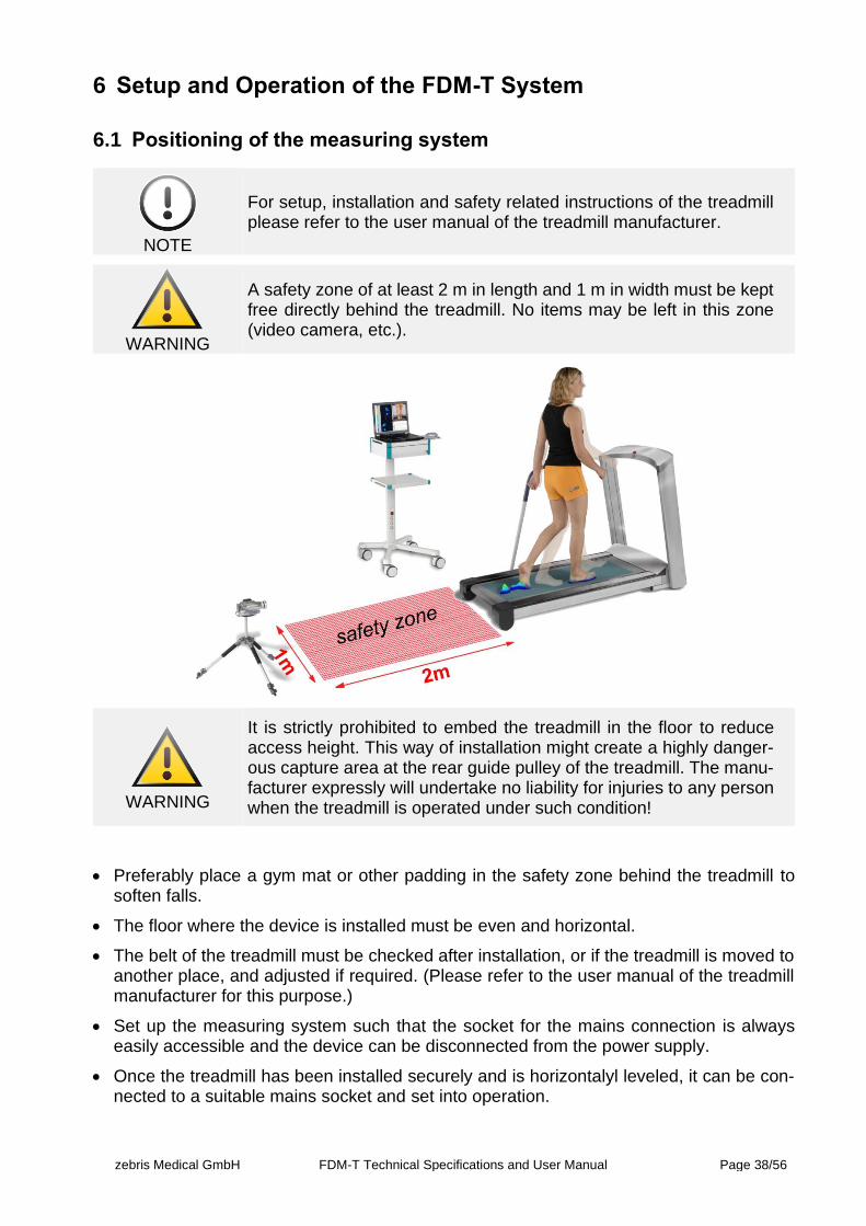
NOTE
For setup, installation and safety related instructions of the treadmill please refer to the user manual of the treadmill manufacturer.
WARNING
A safety zone of at least 2 m in length and 1 m in width must be kept free directly behind the treadmill. No items may be left in this zone (video camera, etc.).
WARNING
It is strictly prohibited to embed the treadmill in the floor to reduce access height. This way of installation might create a highly danger-ous capture area at the rear guide pulley of the treadmill. The manu-facturer expressly will undertake no liability for injuries to any person when the treadmill is operated under such condition!
• Preferably place a gym mat or other padding in the safety zone behind the treadmill to soften falls.
• The floor where the device is installed must be even and horizontal.
• The belt of the treadmill must be checked after installation, or if the treadmill is moved to another place, and adjusted if required. (Please refer to the user manual of the treadmill manufacturer for this purpose.)
• Set up the measuring system such that the socket for the mains connection is always easily accessible and the device can be disconnected from the power supply.
• Once the treadmill has been installed securely and is horizontalyl leveled, it can be con-nected to a suitable mains socket and set into operation.
zebris Medical GmbH FDM-T Technical Specifications and User Manual Page 39/56
For the commissioning of the FDM-T system for the stance and gait analysis, the associated power supply, a USB cable type A-B as well as the installation CD with the zebris FDM application software are necessary. All components are included in the scope of delivery of the FDM-T measuring system.
All cable connections of the FDM-T sensor are integrated in the interface box, which is po-sitioned on the underside of the treadmill frame.<
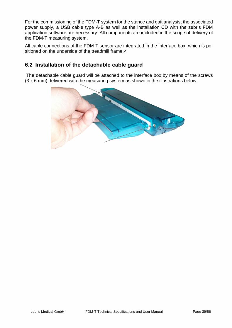
6.2 Installation of the detachable cable guard
The detachable cable guard will be attached to the interface box by means of the screws (3 x 6 mm) delivered with the measuring system as shown in the illustrations below.
zebris Medical GmbH FDM-T Technical Specifications and User Manual Page 40/56
6.3 Connection of the measuring system to mains supply
6.3.1 Power supply of the FDM-T Sensors
For connecting the FDM-T sensor to the power supply, connect the power supply unit to the mains socket and the power socket on the interface box.
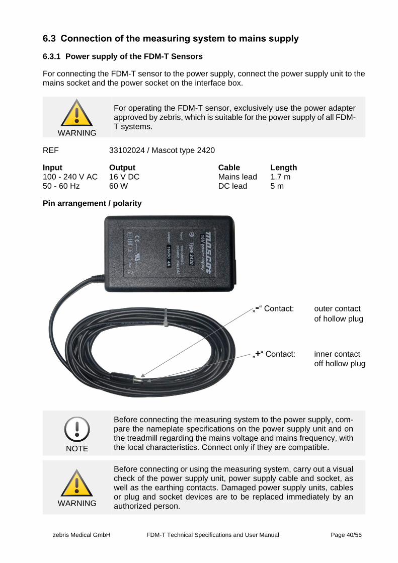
WARNING
For operating the FDM-T sensor, exclusively use the power adapter approved by zebris, which is suitable for the power supply of all FDM-T systems.
REF 33102024 / Mascot type 2420
Input Output Cable Length 100 - 240 V AC 16 V DC Mains lead 1.7 m 50 - 60 Hz 60 W DC lead 5 m
Pin arrangement / polarity
NOTE
Before connecting the measuring system to the power supply, com-pare the nameplate specifications on the power supply unit and on the treadmill regarding the mains voltage and mains frequency, with the local characteristics. Connect only if they are compatible.
WARNING
Before connecting or using the measuring system, carry out a visual check of the power supply unit, power supply cable and socket, as well as the earthing contacts. Damaged power supply units, cables or plug and socket devices are to be replaced immediately by an authorized person.
„-“ Contact: outer contact
of hollow plug
„+“ Contact: inner contact
off hollow plug
zebris Medical GmbH FDM-T Technical Specifications and User Manual Page 41/56
6.3.2 Connection of the System
For connecting the treadmill to the power supply, please additionally observe the respective instructions in the user manual provided by the treadmill manufacturer.
WARNING
The connection of the treadmill and the FDM-T power supply unit must be done at a separate wall socket. It is not permissible to use extension cables and/or multiple sockets.
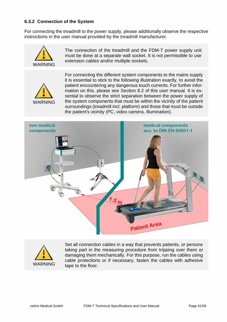
WARNING
For connecting the different system components to the mains supply it is essential to stick to the following illustration exactly, to avoid the patient encountering any dangerous touch currents. For further infor-mation on this, please see Section 8.2 of this user manual. It is es-sential to observe the strict separation between the power supply of the system components that must be within the vicinity of the patient surroundings (treadmill incl. platform) and those that must be outside the patient's vicinity (PC, video camera, illumination).
WARNING
Set all connection cables in a way that prevents patients, or persons taking part in the measuring procedure from tripping over them or damaging them mechanically. For this purpose, run the cables using cable protections or if necessary, fasten the cables with adhesive tape to the floor.
zebris Medical GmbH FDM-T Technical Specifications and User Manual Page 42/56
6.4 IT security and software installation
If the system is not shipped with a computer and properly installed zebris FDM software, the operator is responsible to ensure that the safety of patients, operators and environment is not compromised by the computer. If in question, please contact a dealer authorized by the manufacturer.
For the requirements of the zebris FDM Software with concern to a PC/laptop, please refer to the instructions for use of the zebris FDM Software.
To provide easy integration into an existing system for data backup and to store personal date separately from the PC the data base of the application software can be installed on a network server.
If the database of the zebris FDM software is stored on a storage medium connected via an IT network, the following requirements must be met:
• the data connection must be secured against interference by third parties,
• the data connection must be secured against disconnections,
• applicable data protection regulations must be adhered to for the data connection in the IT network as well as for the location in the IT network,
• access to the location in the IT network must be restricted to the authorized group of persons,
• the exchange of data between the zebris FDM database and the IT system is realized via the SMB protocol,
the exchange of data with third party devices in the IT network is not provided.
WARNING
If the requirements listed above are not met, the following hazardous situations my arise:
• Data loss due to disconnection during data transfer between zebris FDM software and IT network,
• Unauthorized access to personal data by third parties,
• Complete data loss due to missing data backup in the event of dis-ruptions and / or damage to the IT network.
WARNING
The manufacturer is unable to accept any liability for damage or func-tional errors that are caused by faulty software installation or unsuitable computer hardware. If the operator installs additional hardware or third-party software, this occurs based on the sole responsibility of the oper-ator and is not covered by the manufacturer's liability.
The computer needs to be CE-marked and needs to satisfy the require-ments of DIN EN 60950 and/or DIN EN 60601-1.
WARNING
Connecting the system to a network/data pool can cause unforeseen risks to the patient and third parties. The zebris FDM database is not intended for simultaneous use by multiple users.
If the database of the zebris FDM software is installed in a network/data pool, the operator is obliged to ascertain, analyze, evaluate, and man-age all the associated risks. In this context, the aspects of data protec-tion, virus safety, updates to the operating system and regular backups are of particular importance. The risk assessments also have to include
zebris Medical GmbH FDM-T Technical Specifications and User Manual Page 43/56
the subsequent changes to the network/data pool, such as updates/up-grades to devices and components that are connected with the net-work.
The connection of the PC system to the Internet must take place via a professionally maintained IT network in conjunction with a hardware firewall to minimize risks due to the Internet connection. Never use the local computer with Internet access with administrator rights.
WARNING
For the safe operation of the measuring system are the aspects of data protection, virus security, updates of the operating system and regular backups of the zebris FDM database on external data carriers of es-sential importance and to be implemented by the user as measures of IT security.
If the system is delivered without PC/laptop, please install the application software before connecting the platform to the computer. Please find information on the installation in the user manual of the zebris FDM software .
NOTE
If you encounter problems with the hardware driver of the FDM-T system, please disconnect the USB cable from the PC and restart it.
WARNING
Installing a virus scanner on the PC can interfere with the proper func-tioning of the application software. The manufacturer is not liable for damages caused by such programs.
6.5 How to switch the FDM-T sensor On/Off
The FDM-T sensor is switched on and off by software control as soon as the zebris FDM software on the PC is started or shut down.
If the device has been connected correctly, the green power LED lights up on the interface box. For further details on preparing a measurement platform, please see the section "Rec-ommendations for recording data".
6.6 Setting the system out of operation
To set the system out of operation, please close the zebris FDM software first, then exit the Windows operating system and shut down the PC. In the next step disconnect the power supply unit of the FDM sensor and the treadmill from mains supply.
zebris Medical GmbH FDM-T Technical Specifications and User Manual Page 44/56
6.7 Recommendations for recording
There are a few things one should bear in mind for obtaining significant measuring results using the FDM-T system. The following points relate to the data recording of a person while walking and describe the ideal measuring situation.
6.7.1 Treadmill Analysis
Walking on the treadmill is unfamiliar to most people and takes a certain time to get used to it. It is therefore of advantage to familiarize the test person with this new type of externally controlled movement of the treadmill before recording any data.
6.7.2 Data Recording
Also observe the test person during the measurement. Only use data recordings where the foot does not extend beyond the sensor surface during roll-off.
6.7.3 Walking Speed
The walking speed during the measurement should correspond to the person's normal walk-ing speed. It usually takes a few minutes for the test persons to be relaxed enough for finding their normal movement pattern again. It may well be that their speed increases during the measurement. This should be avoided by carefully making sure that the test person feels at ease before the measuring begins. During the data recording the speed should not fluctuate by more than 5%.
6.7.4 Posture
The test person should adopt a relaxed posture, with the arms swinging in a natural way. Make sure that the test person looks straight ahead and not to the ground, the treadmill, or the screen, as this can influence the natural gait pattern.
WARNING
Persons who are unsteady on their feet should make sure to hold onto the handrail while walking on the treadmill to avoid any danger of stumbling!
Basically, the safety features of the treadmill must be used (safety clip for emergency stop, crash bar).
6.7.5 Weals
Studies have proven that the peak plantar pressure is increased by 30 % through calluses on the foot (P.R. Cavanagh, The Foot (1994) 4, 123-135). This information should be taken into account during the measuring procedure.
zebris Medical GmbH FDM-T Technical Specifications and User Manual Page 45/56
7 Maintenance and Safety Inspections
• Scheduled maintenance of the system is essential to prevent damage and guarantees the safety of the device. All processes concerning maintenance and disinfection of the device should be carried out regularly.
• Should any malfunctions and/or defects be determined or suspected, the device must be put out of operation immediately, marked as "Out Of Service" and prevented from being used by removing the mains cable. In such case be sure to contact the manufacturer or an authorized sales partner.
• All maintenance and repair work of the measuring system or of single components that goes beyond the activities described in this user manual must exclusively be carried out by zebris Medical GmbH or a person who has been explicitly authorized by zebris to do so.
• Be sure to switch off the measuring system and disconnect it from mains supply before starting any maintenance work.
7.1 General Maintenance Procedures
• Immediate maintenance procedures are to be carried out if:
a) fluid enters the device.
b) cable or cable connections have been damaged.
c) covers have been damaged or have fallen off.
d) the running belt shows any signs of wear or cracks.
e) the running belt no longer runs centrally.
f) the sliding surface underneath the treadmill belt is no longer sufficiently lubricated.
g) a malfunction or a defect is suspected or has been detected.
• Check regularly (approx. every 25 operating hours) whether all the screws are tight, the belt tension is sufficient, and the running belt is correctly centered. For the exact se-quence of these maintenance procedures, please refer to the user manual supplied by the treadmill manufacturer.
• To keep the friction between the running belt and the FDM-T sensor as low as possible, the system must be lubricated at regular intervals with silicone oil. zebris recommends lubricating at least every 6 months. For detailed information concerning the lubrication procedure please refer to the user manual of the treadmill manufacturer.
• Should the treadmill be relocated to another place, it is necessary to check that the belt is running correctly. The belt should always run centrally on the rear guide pulley.
• After a longer period of use, or if the adjustment is suboptimal, the belt can loosen and with every step, a jolt can occur between the drive shaft and the belt. This can possibly influence the measuring result of the system. Therefore, control the belt tension regularly in accordance with the instructions supplied by the treadmill manufacturer.
• Should you hear "mechanical knocking sounds" during operation, check whether the de-vice is standing level on the ground as incorrectly adjusted feet may often cause knocking noises.
zebris Medical GmbH FDM-T Technical Specifications and User Manual Page 46/56
7.2 Mandatory periodic inspections and STK
• For maintaining the correct state of the electrical equipment, checks and tech-nical safety inspections have to be carried out repeatedly (e.g., within Germany, acc. to BGV A3, and accident prevention regulations and technical safety tests according to the Medical Device Operating Regulations). Here it should be noted that standard regulations for electrical devices are concerned here and not measures that are specific to zebris.
• Before each use of the measuring system, it is recommended for safety reasons to check the correct state of all the connection cables, as well as the mains cable, mains plug and mains socket. Should certain parts be damaged, they must be replaced before continuing to use the measuring system.
• Regular technical safety checks are compulsory for the treadmills. These checks may only be carried out by an authorized qualified electrician. For further information please see the user manual supplied by the treadmill manufacturer.
• For the FDM-T pressure sensors, no technical safety tests are stipulated by zebris Med-ical GmbH.
• If the name plate or other important labels (e.g., warning notes) are damaged or illegible they have to be replaced by the manufacturer for safety reasons.
• Each treadmill has an anti-slip area alongside the running surface on both sides. These stepping areas offer a firm hold when getting off the treadmill in emergencies. Check this anti-slip area at regular intervals and replace it immediately if it shows signs of wear.
zebris Medical GmbH FDM-T Technical Specifications and User Manual Page 47/56
7.3 Maintenance of the FDM-T Sensor
7.3.1 Control Procedures
WARNING
The measuring system must be checked at regular intervals to en-sure its correct function and patient safety.
In case the running belt has been exposed to hard knocks or heavy items have fallen onto it, the surface of the FDM-T sensor has to be checked for damaging (cracks, dents, and scratches on the surface). If visible damages are detected, no further measurements must be carried out.
After carrying out a zero measurement, no measuring values may be shown for a condition without any load. In addition, the pressure distribution images are to be checked regularly for untypical measuring patterns. These include above all, line or column-shaped measuring patterns deviating from the surrounding values.
NOTE
To guarantee the correct functioning of the speedometer in the long term, the central position of the belt must be checked monthly ac-cording to the instructions supplied by the treadmill manufacturer, and readjusted, if required.
Whenever faults occur or in case of doubt, the manufacturer or sales partner authorized by zebris must always be contacted.
7.3.2 Calibration Procedures
The measuring accuracy of the FDM-T sensors is to be checked from time to time using a defined application of pressure.
To do so, the user can stand on the platform on one foot. Provided that he knows his body-weight, the platform must then show the approximate body weight, taking the force of gravity, the sensors at the edges that may not be under full pressure, and the measuring tolerance into consideration.
In case the measuring results show deviations larger than > ± 5 % of the full measuring range, a recalibration by the technical service of zebris Medical is required.
If any doubt exists about the measuring accuracy of the FDM-T sensor, it is recommended to have the pressure distribution measuring sensors checked and re-calibrated by zebris, to ensure the specified measuring accuracy.
NOTE
On request, service instructions for the assembly and disassembly of the FDM-T sensor can be supplied for various treadmill types, so that maintenance and repair work can be carried out by trained personnel on site.
zebris Medical GmbH FDM-T Technical Specifications and User Manual Page 48/56
7.4 Troubleshooting
In the case of faults, please check the following points first:
✓ Are the FDM-T sensor and treadmill connected correctly to the mains? (Green Power LED on the interface box and power switch on the treadmill lights up.)
✓ Is the USB connection between the interface box and the measuring PC correct? (Green USB LED lights up when the USB is connected to the PC and the device driver is correctly installed.)
✓ Are all the other components of the measuring system (infrared synchronization with zebris DAB Bluetooth, video camera) connected correctly?
NOTE
For additional information on error messages and their troubleshoot-ing, please refer to the user manual for the zebris FDM software.
Check list for noting down error messages:
NOTE
To provide best possible support in the event of system malfunctions our service personnel will need the following information:
✓ Device type + serial no. of the FDM-T sensor and treadmill
The serial no. can be found on the type plates on the frame of the treadmill or on the back of the interface box.
✓ Version of the zebris FDM Software
✓ Data on the operating system of your measuring PC
e.g., Windows 7 Service Pack 1 (can be found under Start >> Properties>> Control Panel>> System)
✓ Further components connected to the measuring system
e.g., infrared synchronization (IR) with zebris DAB Bluetooth, video camera
✓ List of all the USB devices connected to the measuring PC
e.g., mouse, printer, other measuring systems, etc.
✓ Screenshot of the error message or exact wording
e.g., "EMG adapter not found."
✓ User's procedure leading to the error message
e.g., measurement "Type A" started, then clicked on button "B", then movement "C" carried out, switch-over to function "D", when switching back the described error message occurred.
zebris Medical GmbH FDM-T Technical Specifications and User Manual Page 49/56
7.5 Cleaning and disinfection
7.5.1 Cleaning Procedure
The treadmill and components are cleaned with a moist cloth while the device is switched off and the mains plug taken out.
NOTE
Do not use any aggressive agents to clean the measuring system.
WARNING
Please make sure to switch off the device and pull the mains plug out of the socket before you commence disinfecting and cleaning.
7.5.2 Disinfection Procedure
The treadmill can be disinfected by wiping over with suitable detergents. Best wipe the run-ning belt or other parts of the treadmill with a cloth soaked with disinfection liquid. To remove more resistant contamination directly spray the running belt with disinfection liquid.
Recommended disinfection agent:
Composition approx. 25% ethanol, 35% propanol
E.g., Mikrozid Liquid / Schülke & Mayr or similar solutions
NOTE
If you apply disinfectant be sure to strictly follow the recommenda-tions provided by the manufacturer of the disinfectant. Especially consider the rules concerning the disinfectant’s recommended dura-tion of impact.
WARNING
On no account bring any disinfection fluids or other liquids in direct contact with the FDM-T sensor when cleaning.
Should any liquid enter the platform it is likely to be damaged irrepa-rably.
WARNING
Fluids required for disinfecting and cleaning must be stored, pre-pared, and kept ready for use exclusively in the containers provided, to avoid them being mistaken for other fluids.
NOTE
For confirmation that disinfection has been carried out, it is advised to place a visible sign on the running surface reading "disinfected".
zebris Medical GmbH FDM-T Technical Specifications and User Manual Page 50/56
7.6 Disposal
7.6.1 Packaging
All the transport packaging supplied by zebris can be recycled within Germany via the local recycling depots. To guarantee the re-use of the recyclables contained in the packaging, zebris Medical GmbH partici-pates in the Dual System ZENTEK which takes over the proper disposal of the packaging.
Please find information concerning the disposal of the treadmill in the Operating Instructions supplied by the treadmill manufacturer.
7.6.2 WEEE-Directive
This symbol indicates that according to the directive on waste electrical and electronic equipment (2012/19/EEC) the product must not be disposed by means of the domestic waste system. Within Europe this device must be forwarded to a specific waste disposal system.
For this purpose, the measuring system can be returned to zebris Medical GmbH at the end of its service life at the customer’s own expense and will be forwarded to special recycling companies without any further costs and refund.
The improper use of old devices (measuring systems) could lead to negative effects for the environment and the public health be-cause of potential hazardous materials which are frequently con-tained within electric and electronic devices. Additionally, with the proper disposal of this product you will contribute to the effective use of natural resources.
7.6.3 Accumulators and batteries
Accumulators and batteries must not be disposed of with domestic waste! In the interest of environmental protection, the consumer is legally obliged (battery regulation) to return old and used batteries. Used accumulators and batteries can be disposed of at the collecting points of the community or where batteries of the relevant kind are sold. For consumers, the batteries are taken back free of charge.
zebris Medical GmbH FDM-T Technical Specifications and User Manual Page 51/56
8 Safety standards and classification of the system
The following information and warnings are based on requirements of the Standard EN 60601-1:2013, Section 16 for Medical Electrical Equipment and for the application of the FDM-T system for medical purposes.
NOTE
The sections 8.1 – 8.3 are only applicable for the FDM-T sensor in-tegrated in the treadmill and the components listed in this User Man-ual. Please find information concerning the disposal of the treadmill in the Operating Instructions of the treadmill manufacturer.
8.1 Classification acc. to Annex IX of Directive 93/42/EEC
The system is then classified as medical product Class I with measuring function.
8.2 Safety of medical electrical device
The system meets the requirements of the standards EN 60601-1:2013
Classification according to EN 60601-1
Type BF
Safety class II
Steady state conditions
Unsuitable for use in an oxygen-enriched atmosphere
8.2.1 Coupling of the FDM-T measuring system with other electrical devices
(refer to EN 60601-1:2013 Par. 16 Medical electrical equipment)
WARNING
The FDM-T System may only be coupled with other electrical devices if these conform to the provisions of EN 60950 or EN 60601-1 or zebris Medical GmbH has confirmed their compatibility.
WARNING
When coupling several devices to a measuring system, care must be taken to avoid any danger arising from the summation of the leakage currents.
In the case of devices that the patient comes into direct contact with, and that are used together in one medical, electrical system, they must adhere to the requirements of EN 60601-1:2013 Section 16.
There is a danger of an electric shock if devices are touched that have not been connected to ground separately.
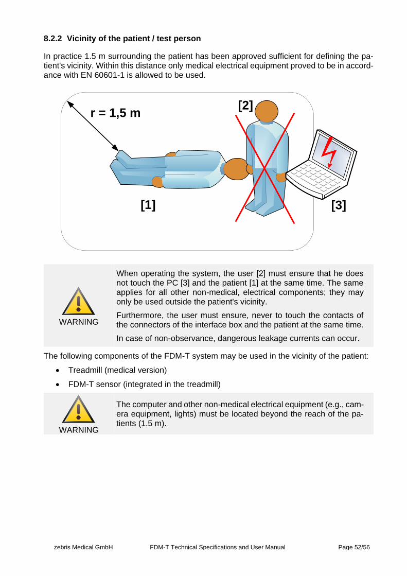
zebris Medical GmbH FDM-T Technical Specifications and User Manual Page 52/56
8.2.2 Vicinity of the patient / test person
In practice 1.5 m surrounding the patient has been approved sufficient for defining the pa-tient's vicinity. Within this distance only medical electrical equipment proved to be in accord-ance with EN 60601-1 is allowed to be used.
r = 1,5 m
[1] [3]
[2]
WARNING
When operating the system, the user [2] must ensure that he does not touch the PC [3] and the patient [1] at the same time. The same applies for all other non-medical, electrical components; they may only be used outside the patient's vicinity.
Furthermore, the user must ensure, never to touch the contacts of the connectors of the interface box and the patient at the same time.
In case of non-observance, dangerous leakage currents can occur.
The following components of the FDM-T system may be used in the vicinity of the patient:
• Treadmill (medical version)
• FDM-T sensor (integrated in the treadmill)
WARNING
The computer and other non-medical electrical equipment (e.g., cam-era equipment, lights) must be located beyond the reach of the pa-tients (1.5 m).
zebris Medical GmbH FDM-T Technical Specifications and User Manual Page 53/56
8.2.3 Use of multiple sockets
The following information and warnings are based on the requirements of the Standard EN 60601-1:2013, Section 16 for medical electrical equipment and must be enforced when the FDM-T system is used for medical purposes.
WARNING
If multiple sockets are used for connecting the FDM-T system or its components, the following safety regulations are to be observed:
• Always connect the treadmill and FDM-T sensor directly to mains supply by using a sep-arate wall socket with a tested protective earth conductor and separate fuse.
• Multiple sockets can be used without causing any danger for connecting the PC and other electrical devices (video camera, illumination) outside the patients’ vicinity.
• Multiple sockets must not be placed on the floor to avoid accidentally penetration of liquids or mechanical damages.
• It is forbidden to use extension cables, or several multiple sockets connected in series.
• In commercially available multiple sockets, system components set up within and outside the vicinity of the patient must never be plugged in together. (Example: It is forbidden to connect the PC and the power supply unit of the FDM-T sensors to the same multiple sockets.)
• If multiple sockets are used jointly for components of the FDM-T system, that can be located within the vicinity of the patient (e.g., treadmill, FDM-T sensor or other zebris measuring systems) and components that have to be outside the vicinity of the patient (e.g., PC, video camera), the multiple socket and complete interconnection of the system must adhere to all the requirements of EN 60601-1:2013 Section 16. If necessary, an isolating transformer is to be used for an arrangement of this kind, and the ground leakage current in the protective earth conductor of the multiple sockets must not exceed 5 mA. The adherence to the maximum permissible patient leakage currents is to be verified by measuring. If a multiple socket was integrated after setting the system into operation for the first time, no additional device may be connected to it (use multiple sockets with lock-ing covers for this purpose)
WARNING
It is extremely dangerous to use multiple sockets for combining the mains connection of components of Medical Electrical Equipment Systems with other components that have not been supplied at the same time.
It is possible for excessive touch currents to occur if mains are con-nected without the user having any respective expert knowledge.
Due to these complications zebris Medical GmbH urgently advises not to use multiple sockets for operation of the system.
zebris Medical GmbH FDM-T Technical Specifications and User Manual Page 54/56
8.3 Electromagnetic Compatibility / Manufacturer's Declaration
The measuring system FDM-T fulfills all requirements for EN 60601-1-2.
Detailed information on EMC values and information supplied by the manufacturer can be found in the tables in this section of the user manual.
Electrical equipment in the medical field is subject to precautionary measures as regards the EMC (Electromagnetic Compatibility) and must be installed and put into operation in accordance with the instructions given below.
WARNING
Even though the motion analysis system FDM-T fully complies with the requirements of the standard EN 60601-1 it cannot be totally ac-cepted that portable and mobile RF communications equipment can affect the system. If ever possible such devices should not be oper-ated within the system environment during measurements.
WARNING
The use of accessories, particularly cables for connecting to the PC, that are not supplied by zebris for use with the FDM-T system, or explicitly recommended for use with the device, can lead to a reduced resistance to EMC interference of the FDM-T system.
WARNING
The FDM-T measuring system should not be operated in the vicinity of e.g., X-ray equipment, motors, or transformers with a high con-nected load, as electrical or magnetic interference fields can influ-ence the measurements. The same is applicable for neighboring power lines and equipment without a CE mark. Should operation next to possible sources of interferences be necessary it is mandatory to check and verify the correct function of the system.
NOTE
In the case of over voltages or voltage dips (even short-term) of more than 50% of the mains voltage, functional faults can occur. When such high voltage dips or complete voltage failures occur, the meas-urement is interrupted, and the measuring data is discarded. Finally, the measurement must be re-started, and if need be, also the con-nected PC.

zebris Medical GmbH FDM-T Technical Specifications and User Manual Page 55/56
Guidelines and Manufacturer's Statement - Electromagnetic Emission
The FDM-T pressure-distribution measuring system is intended for use in the electromagnetic environment described below. The cus-tomer or user of the FDM-T pressure -distribution measuring system should ensure that it is operated in such an environment.
Emitted interference measure-ments
Compliance Electromagnetic environment guidelines
RF emissions acc. to CISPR 11
Group 1 The FDM-T pressure -distribution measuring system uses RF energy exclusively for its internal functions. Therefore, its RF emission is very low, and it is unlikely that electronic equipment in close proximity will experience interference.
RF emissions acc. to CISPR 11
class B The FDM-T pressure -distribution measuring system is intended for use in all facilities including those in residential areas and those di-rectly connected to a public utility network also supplying buildings used for residential purposes. Emission of harmonic oscillations
acc. to IEC 61000-3-2 class B
Emission of voltage fluctuations / flickers acc. to IEC61000-3-3
in compliance
Guidelines and Manufacturer's Statement - Electromagnetic Interference Immunity
The FDM-T pressure -distribution measuring system is intended for use in the electromagnetic environment described below. The customer or user of the FDM-T pressure -distribution measuring system should ensure that it is operated in such an environment.
Interference immunity tests
IEC 60601 test levels Compliance level Electromagnetic environment guide-lines
Electrostatic discharge (ESD) acc. to IEC 61000-4-2
± 6 kV contact discharge
± 8 kV atmospheric discharge
± 6 kV contact discharge
± 8 kV atmospheric discharge
Flooring should be of wood or concrete or laid with ceramic tiles. If the flooring is made of synthetic material, the relative humidity must be at least 30%.
Fast transient electrical interfer-ences/bursts acc. to IEC 61000-4-4
± 2 kV for power lines
± 1 kV for input and output lines
± 2 kV for power lines
± 1 kV for input and output lines
The quality of the supply voltage should be the same as the voltage of a typical busi-ness or hospital environment.
Surges acc. to IEC 61000-4-5
± 1 kV differential mode voltage
± 2 kV common mode voltage
± 1 kV differential mode voltage
± 2 kV common mode voltage
The quality of the supply voltage should be the same as the voltage of a typical busi-ness or hospital environment.
Blackouts, brownouts and fluctuations of the power supply acc. to IEC 61000-4-11
< 5% UT (> 95% crash of the UT) for ½ period
40% UT (60% crash of the UT) for 5 periods
70% UT (30% crash of the UT) for 25 periods
< 5% UT (> 95% crash of the UT) for 5 s
< 5% UT (> 95% crash of the UT) for ½ period
40% UT (60% crash of the UT) for 5 periods
70% UT (30% crash of the UT) for 25 periods
< 5% UT (> 95% crash of the UT) for 5 s
The quality of the supply voltage should be the same as the voltage of a typical busi-ness or hospital environment. If the user of the FDM-T pressure-distribution measuring system requires the continuation of func-tionality also after power interruptions/dis-ruptions, it is recommended to provide the FDM-T pressure-distribution measuring system with power from an uninterruptible power supply.
Magnetic field with supply frequency (50/60 Hz) acc. to IEC 61000-4-8
3 A/m Not tested as no influence is possible on the device within the specified test level. (see Note B)
Magnetic fields of the mains power fre-quency should comply with the typical val-ues of a business and hospital environ-ment.
NOTE UT is the AC main voltage prior to applying the test levels.
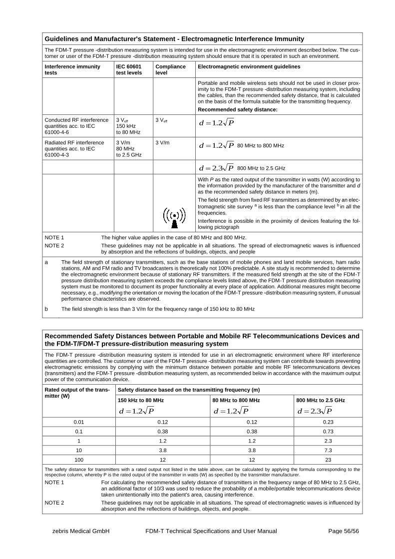
zebris Medical GmbH FDM-T Technical Specifications and User Manual Page 56/56
Guidelines and Manufacturer's Statement - Electromagnetic Interference Immunity
The FDM-T pressure -distribution measuring system is intended for use in the electromagnetic environment described below. The cus-tomer or user of the FDM-T pressure -distribution measuring system should ensure that it is operated in such an environment.
Interference immunity tests
IEC 60601 test levels
Compliance level
Electromagnetic environment guidelines
Portable and mobile wireless sets should not be used in closer prox-imity to the FDM-T pressure -distribution measuring system, including the cables, than the recommended safety distance, that is calculated on the basis of the formula suitable for the transmitting frequency.
Recommended safety distance:
Conducted RF interference quantities acc. to IEC 61000-4-6
3 Veff
150 kHz to 80 MHz
3 Veff Pd 2.1=
Radiated RF interference quantities acc. to IEC 61000-4-3
3 V/m 80 MHz to 2.5 GHz
3 V/m Pd 2.1= 80 MHz to 800 MHz
Pd 3.2= 800 MHz to 2.5 GHz
With P as the rated output of the transmitter in watts (W) according to the information provided by the manufacturer of the transmitter and d as the recommended safety distance in meters (m).
The field strength from fixed RF transmitters as determined by an elec-
tromagnetic site survey a is less than the compliance level b in all the
frequencies.
Interference is possible in the proximity of devices featuring the fol-lowing pictograph
NOTE 1 The higher value applies in the case of 80 MHz and 800 MHz. NOTE 2 These guidelines may not be applicable in all situations. The spread of electromagnetic waves is influenced by absorption and the reflections of buildings, objects, and people
a The field strength of stationary transmitters, such as the base stations of mobile phones and land mobile services, ham radio stations, AM and FM radio and TV broadcasters is theoretically not 100% predictable. A site study is recommended to determine the electromagnetic environment because of stationary RF transmitters. If the measured field strength at the site of the FDM-T pressure distribution measuring system exceeds the compliance levels listed above, the FDM-T pressure distribution measuring system must be monitored to document its proper functionality at every place of application. Additional measures might become necessary, e.g., modifying the orientation or moving the location of the FDM-T pressure -distribution measuring system, if unusual performance characteristics are observed.
b The field strength is less than 3 V/m for the frequency range of 150 kHz to 80 MHz
Recommended Safety Distances between Portable and Mobile RF Telecommunications Devices and the FDM-T/FDM-T pressure-distribution measuring system
The FDM-T pressure -distribution measuring system is intended for use in an electromagnetic environment where RF interference quantities are controlled. The customer or user of the FDM-T pressure -distribution measuring system can contribute towards preventing electromagnetic emissions by complying with the minimum distance between portable and mobile RF telecommunications devices (transmitters) and the FDM-T pressure -distribution measuring system, as recommended below in accordance with the maximum output power of the communication device.
Rated output of the trans-mitter (W)
Safety distance based on the transmitting frequency (m)
150 kHz to 80 MHz
Pd 2.1=
80 MHz to 800 MHz
Pd 2.1=
800 MHz to 2.5 GHz
Pd 3.2=
0.01 0.12 0.12 0.23
0.1 0.38 0.38 0.73
1 1.2 1.2 2.3
10 3.8 3.8 7.3
100 12 12 23
The safety distance for transmitters with a rated output not listed in the table above, can be calculated by applying the formula corresponding to the respective column, whereby P is the rated output of the transmitter in watts (W) as specified by the transmitter manufacturer.
NOTE 1 For calculating the recommended safety distance of transmitters in the frequency range of 80 MHz to 2.5 GHz, an additional factor of 10/3 was used to reduce the probability of a mobile/portable telecommunications device taken unintentionally into the patient's area, causing interference.
NOTE 2 These guidelines may not be applicable in all situations. The spread of electromagnetic waves is influenced by absorption and the reflections of buildings, objects, and people.