Specification of MEMS silicon microphone - endrich.com · Microphone Technology Leadership 1....
20
BEST SOUND ELECTRONICS Microphone Technology Leadership V 1.3 BSE CO., LTD 58B-4L, 626-3, GOZAN-DONG, NAMDONG-KU INCHON-SI. KOREA TEL :(8232) 550-1780 FAX :(8232) 554-6206 4 0 5 8 1 7 - SPECIFICATION OF ANALOG MEMS MICROPHONE DIRECTIVITY : OMNI-DIRECTIONAL SOUND PORT : BOTTOM PORT TYPE DATE : 2013. 09. 04 HF BFRs/CFRs/PVC - Free HF BFRs/CFRs/PVC - Free ※ Halogen Free MODEL NO. : MOE-C110R38-K1 USER Prepared Checked Checked Approved Name Sign BSE Prepared Checked Checked Approved Name Y.H.Shim S.H.Lee M.J.Lee Sign 1 ( Ultra Mini Bottom Port )
Transcript of Specification of MEMS silicon microphone - endrich.com · Microphone Technology Leadership 1....
BEST SOUND ELECTRONICS
Microphone Technology Leadership
V 1.3
BSE CO., LTD 58B-4L, 626-3, GOZAN-DONG, NAMDONG-KU INCHON-SI. KOREA TEL :(8232) 550-1780 FAX :(8232) 554-6206
4 0 5 8 1 7 -
SPECIFICATION OF
ANALOG MEMS MICROPHONE
DIRECTIVITY : OMNI-DIRECTIONAL
SOUND PORT : BOTTOM PORT TYPE
DATE : 2013. 09. 04
H FBFRs/CFRs/PVC - Free
H FBFRs/CFRs/PVC - Free
※ Halogen Free
MODEL NO. : MOE-C110R38-K1
USER
Prepared Checked Checked Approved
Name
Sign
BSE
Prepared Checked Checked Approved
Name Y.H.Shim S.H.Lee M.J.Lee
Sign
1
( Ultra Mini Bottom Port )
BEST SOUND ELECTRONICS
Microphone Technology Leadership
V 1.3
Version Date Comments
1.0 Jan, 14, 13 1ST Submission of Electro-Acoustical specification
1.1 Mar. 15. 13 Added Inner & Outer Box Spec.
1.2 Aug. 12. 13 Edited Reel Specification
1.3 Sep. 04. 13 Edited Sensitivity Specification
SPECIFICATION HISTORY
2
BEST SOUND ELECTRONICS
Microphone Technology Leadership
V 1.3
1. INTRODUCTION
This specification is for the SMD possible Analog MEMS (Bottom port) Microphone which has endurable
reflow temperature of up to 260 for over 15 seconds.
2. MODEL NO.
MOE-C110R38-K1
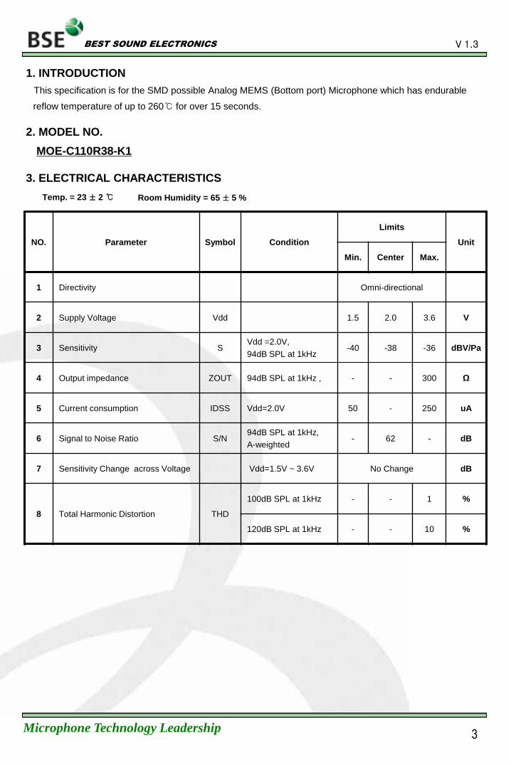
3. ELECTRICAL CHARACTERISTICS
Temp. = 23 ± 2 Room Humidity = 65 ± 5 %
NO. Parameter Symbol Condition
Limits
Unit
Min. Center Max.
1 Directivity Omni-directional
2 Supply Voltage Vdd 1.5 2.0 3.6 V
3 Sensitivity S Vdd =2.0V,
94dB SPL at 1kHz -40 -38 -36 dBV/Pa
4 Output impedance ZOUT 94dB SPL at 1kHz , - - 300 Ω
5 Current consumption IDSS Vdd=2.0V 50 - 250 uA
6 Signal to Noise Ratio S/N 94dB SPL at 1kHz,
A-weighted - 62 - dB
7 Sensitivity Change across Voltage Vdd=1.5V ~ 3.6V No Change dB
8 Total Harmonic Distortion THD
100dB SPL at 1kHz - - 1 %
120dB SPL at 1kHz - - 10 %
3
BEST SOUND ELECTRONICS
Microphone Technology Leadership
V 1.3
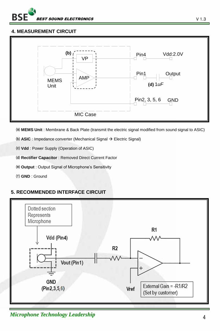
4. MEASUREMENT CIRCUIT
5. RECOMMENDED INTERFACE CIRCUIT
VP
MEMS Unit
AMP
Pin4
Pin1
Pin2, 3, 5, 6
1 uF
Vdd:2.0V
Output
GND
MIC Case
MEMS Unit : Membrane & Back Plate (transmit the electric signal modified from sound signal to ASIC)
ASIC : Impedance converter (Mechanical Signal Electric Signal)
Vdd : Power Supply (Operation of ASIC)
Rectifier Capacitor : Removed Direct Current Factor
Output : Output Signal of Microphone’s Sensitivity
GND : Ground
(b)
(d)
4
BEST SOUND ELECTRONICS
Microphone Technology Leadership
V 1.3
MOE-C110R38-K1
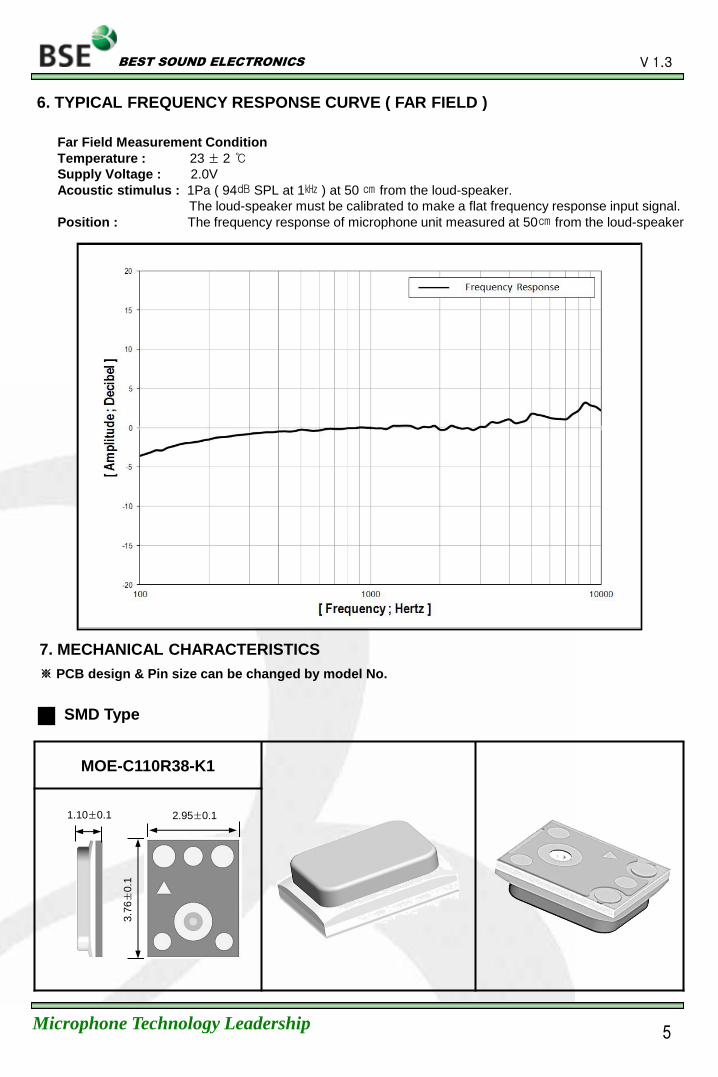
6. TYPICAL FREQUENCY RESPONSE CURVE ( FAR FIELD )
Far Field Measurement Condition
Temperature : 23 ± 2
Supply Voltage : 2.0V
Acoustic stimulus : 1Pa ( 94 SPL at 1 ) at 50 from the loud-speaker.
The loud-speaker must be calibrated to make a flat frequency response input signal.
Position : The frequency response of microphone unit measured at 50 from the loud-speaker
3.7
6±
0.1
2.95±0.1 1.10±0.1
SMD Type
7. MECHANICAL CHARACTERISTICS
※ PCB design & Pin size can be changed by model No.
5
BEST SOUND ELECTRONICS
Microphone Technology Leadership
V 1.3
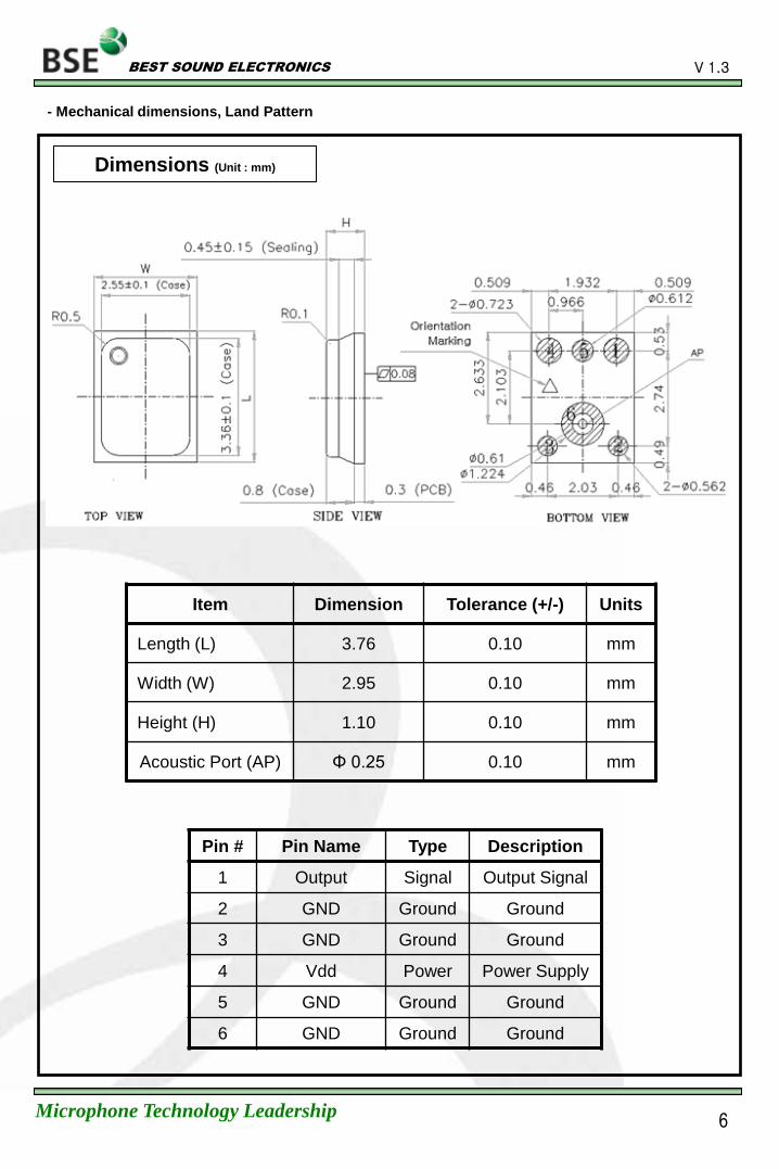
- Mechanical dimensions, Land Pattern
Dimensions (Unit : mm)
Item Dimension Tolerance (+/-) Units
Length (L) 3.76 0.10 mm
Width (W) 2.95 0.10 mm
Height (H) 1.10 0.10 mm
Acoustic Port (AP) Φ 0.25 0.10 mm
Pin # Pin Name Type Description
1 Output Signal Output Signal
2 GND Ground Ground
3 GND Ground Ground
4 Vdd Power Power Supply
5 GND Ground Ground
6 GND Ground Ground
6
BEST SOUND ELECTRONICS
Microphone Technology Leadership
V 1.3
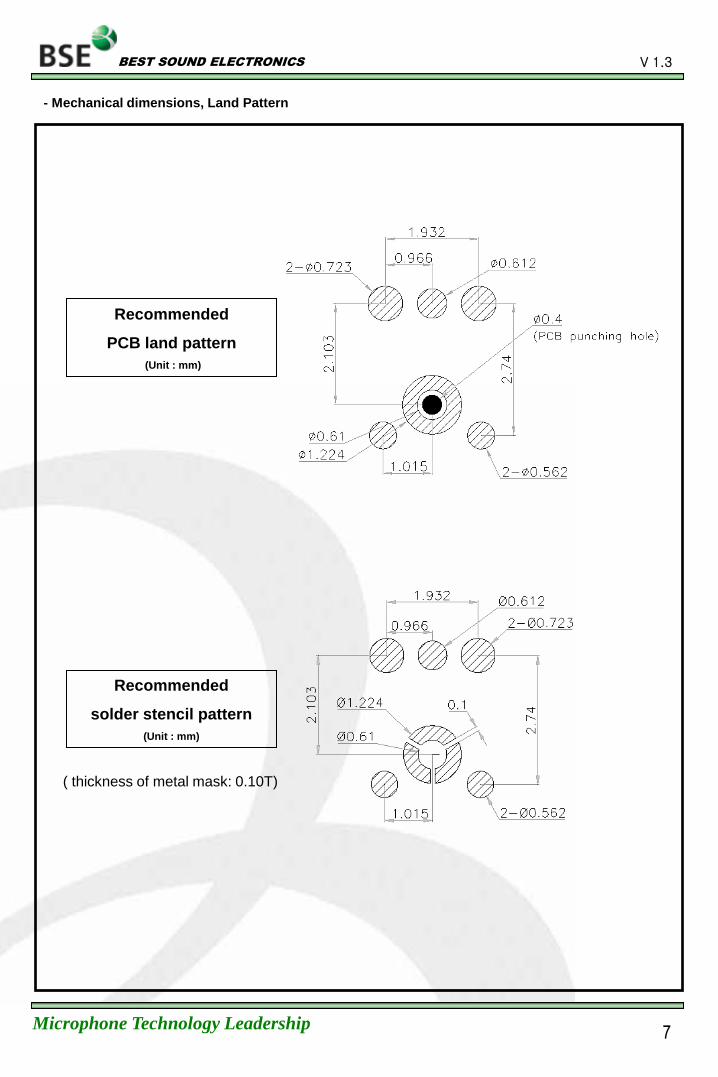
- Mechanical dimensions, Land Pattern
Recommended
PCB land pattern
(Unit : mm)
Recommended
solder stencil pattern
(Unit : mm)
( thickness of metal mask: 0.10T)
7
BEST SOUND ELECTRONICS
Microphone Technology Leadership
V 1.3
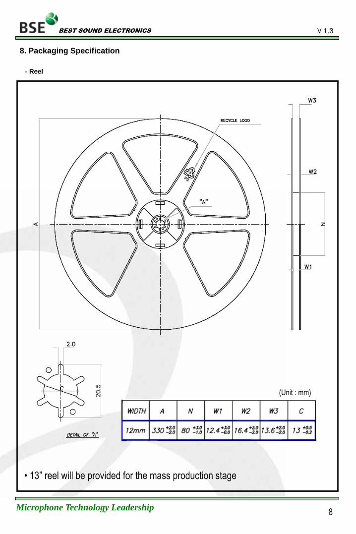
8. Packaging Specification
- Reel
8
(Unit : mm)
• 13” reel will be provided for the mass production stage
BEST SOUND ELECTRONICS
Microphone Technology Leadership
V 1.3
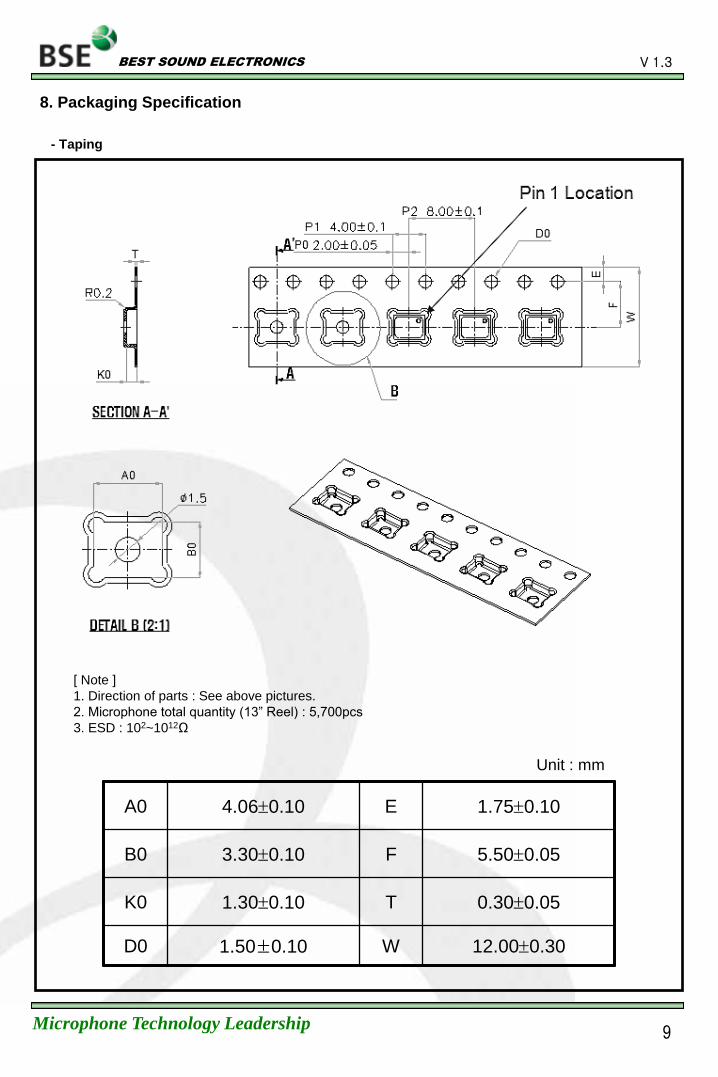
Unit : mm
A0 4.060.10 E 1.750.10
B0 3.300.10 F 5.500.05
K0 1.300.10 T 0.300.05
D0 1.50±0.10 W 12.000.30
[ Note ]
1. Direction of parts : See above pictures.
2. Microphone total quantity (13” Reel) : 5,700pcs
3. ESD : 102~1012Ω
8. Packaging Specification
- Taping
9
BEST SOUND ELECTRONICS
Microphone Technology Leadership
V 1.3
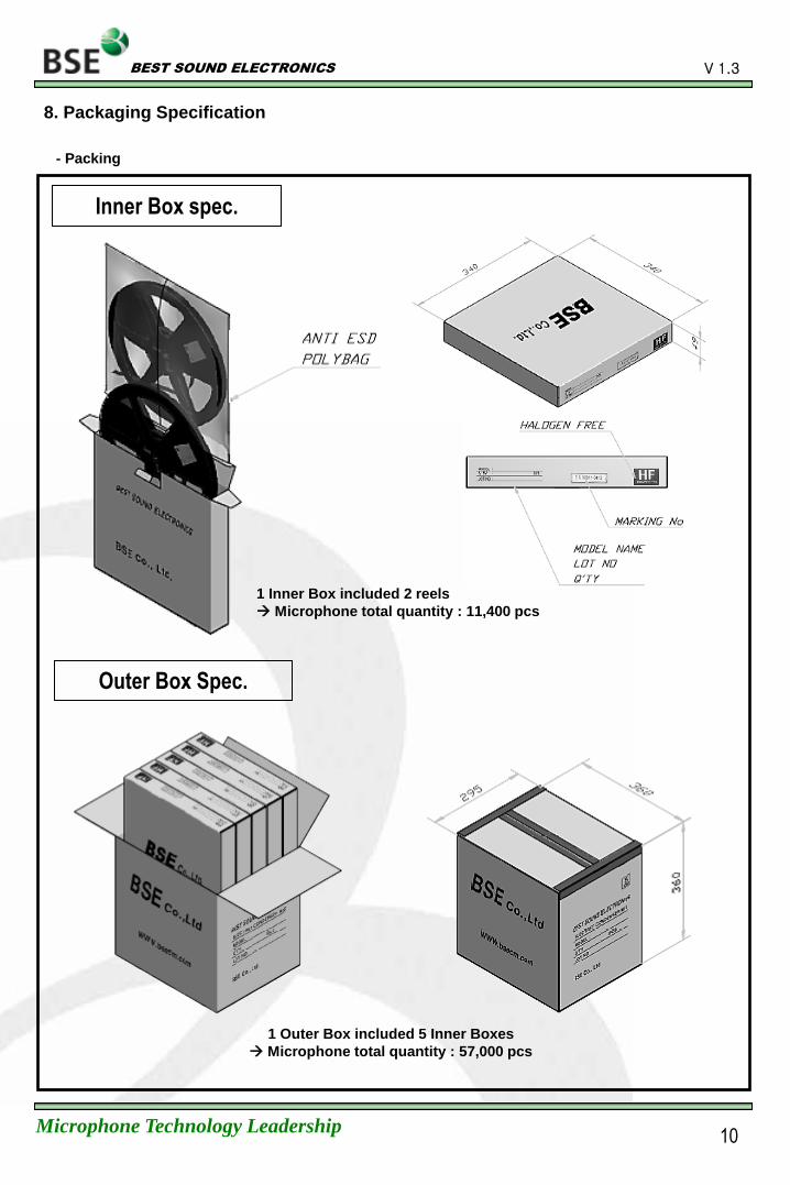
8. Packaging Specification
- Packing
Inner Box spec.
Outer Box Spec.
1 Inner Box included 2 reels
Microphone total quantity : 11,400 pcs
1 Outer Box included 5 Inner Boxes
Microphone total quantity : 57,000 pcs
10
BEST SOUND ELECTRONICS
Microphone Technology Leadership
V 1.3
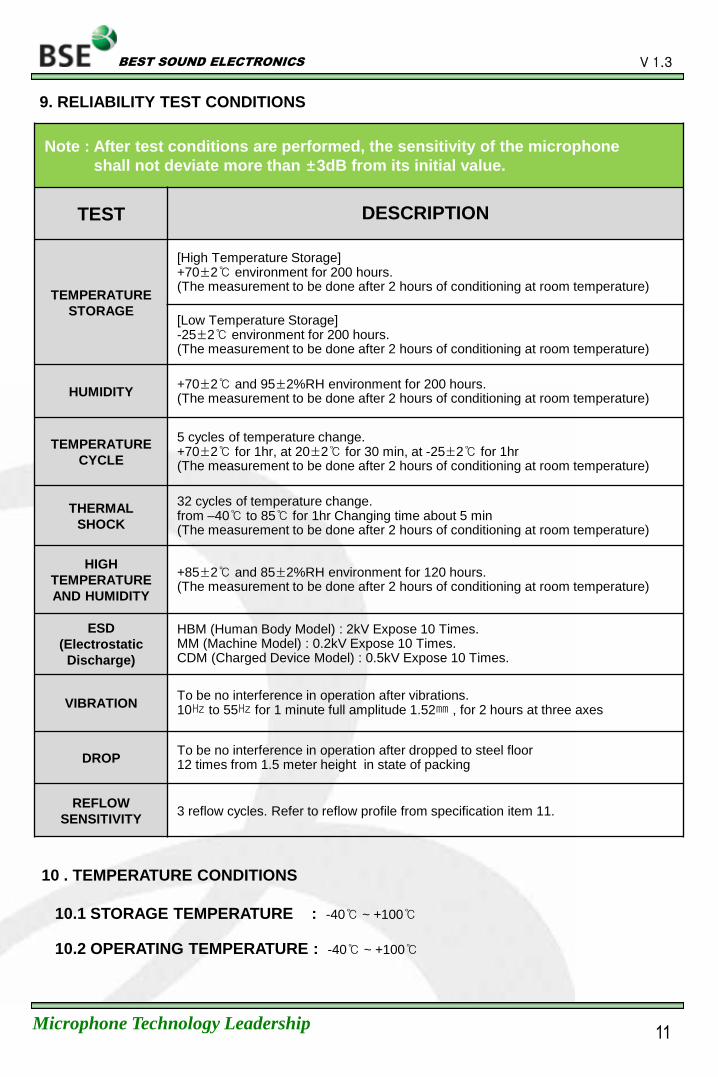
9. RELIABILITY TEST CONDITIONS
10 . TEMPERATURE CONDITIONS
10.1 STORAGE TEMPERATURE : -40 ~ +100
10.2 OPERATING TEMPERATURE : -40 ~ +100
Note : After test conditions are performed, the sensitivity of the microphone
shall not deviate more than ±3dB from its initial value.
TEST DESCRIPTION
TEMPERATURE
STORAGE
[High Temperature Storage] +70±2 environment for 200 hours. (The measurement to be done after 2 hours of conditioning at room temperature)
[Low Temperature Storage] -25±2 environment for 200 hours. (The measurement to be done after 2 hours of conditioning at room temperature)
HUMIDITY +70±2 and 95±2%RH environment for 200 hours. (The measurement to be done after 2 hours of conditioning at room temperature)
TEMPERATURE
CYCLE
5 cycles of temperature change. +70±2 for 1hr, at 20±2 for 30 min, at -25±2 for 1hr (The measurement to be done after 2 hours of conditioning at room temperature)
THERMAL
SHOCK
32 cycles of temperature change. from –40 to 85 for 1hr Changing time about 5 min (The measurement to be done after 2 hours of conditioning at room temperature)
HIGH
TEMPERATURE
AND HUMIDITY
+85±2 and 85±2%RH environment for 120 hours. (The measurement to be done after 2 hours of conditioning at room temperature)
ESD
(Electrostatic
Discharge)
HBM (Human Body Model) : 2kV Expose 10 Times. MM (Machine Model) : 0.2kV Expose 10 Times. CDM (Charged Device Model) : 0.5kV Expose 10 Times.
VIBRATION To be no interference in operation after vibrations. 10 to 55 for 1 minute full amplitude 1.52 , for 2 hours at three axes
DROP To be no interference in operation after dropped to steel floor 12 times from 1.5 meter height in state of packing
REFLOW
SENSITIVITY 3 reflow cycles. Refer to reflow profile from specification item 11.
11

BEST SOUND ELECTRONICS
Microphone Technology Leadership
V 1.3
11. MEASUREMENT SYSTEM
11.1 Measurement Condition
(a) Supply voltage : 2.0V
(b) Acoustic stimulus : 94 SPL at 1
(c) Distance between MIC & SPK : 50
(d) Measurement frequency : 80 () ∼ 16 ()
Machine Model No Purpose
Standard MIC 4191 Revision of input signal & SPK spec
Pulse Analyzer 3560C Electric-Sound Signal occurrence and analysis
C-Microphone Interface BK2010 Voltage & impedance supply to MIC
Power Amplifier 2716C Input Signal amplifying purpose
Turn Table 5997 MIC directionality Test purpose
Loud Speaker GRF Memory HE SPK (Input sound Signal occur)
Operating Software Lab-Shop 13.0 Machine control Software
Sound Level Calibrator 4231 Standard MIC Calibration purpose
12
BEST SOUND ELECTRONICS
Microphone Technology Leadership
V 1.3
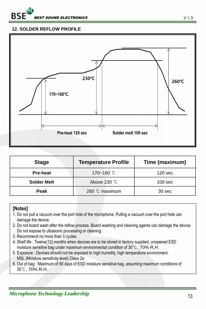
12. SOLDER REFLOW PROFILE
170~180
Pre-heat 120 sec
230 260
Solder melt 100 sec
Stage Temperature Profile Time (maximum)
Pre-heat 170~180 120 sec
Solder Melt Above 230 100 sec
Peak 260 maximum 30 sec
[Notes] 1. Do not pull a vacuum over the port hole of the microphone. Pulling a vacuum over the port hole can
damage the device.
2. Do not board wash after the reflow process. Board washing and cleaning agents can damage the device.
Do not expose to ultrasonic processing or cleaning.
3. Recommend no more than 3 cycles.
4. Shelf life : Twelve(12) months when devices are to be stored in factory supplied, unopened ESD
moisture sensitive bag under maximum environmental condition of 30, 70% R.H.
5. Exposure : Devices should not be exposed to high humidity, high temperature environment.
MSL (Moisture sensitivity level) Class 2a.
6. Out of bag : Maximum of 90 days of ESD moisture sensitive bag, assuming maximum conditions of
30, 70% R.H.
13
BEST SOUND ELECTRONICS
Microphone Technology Leadership
V 1.3
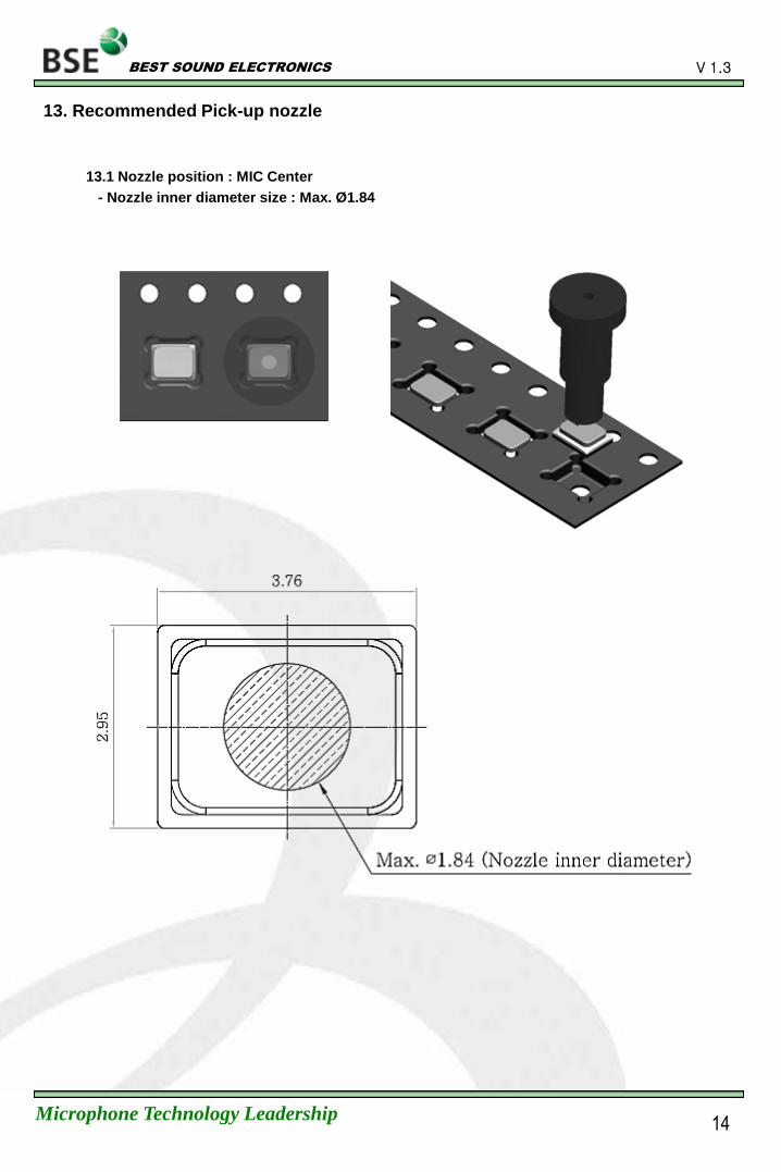
13. Recommended Pick-up nozzle
13.1 Nozzle position : MIC Center
- Nozzle inner diameter size : Max. Ø 1.84
14
BEST SOUND ELECTRONICS
Microphone Technology Leadership
V 1.3
15
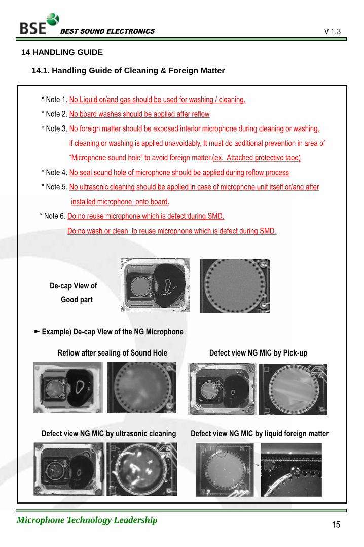
* Note 1. No Liquid or/and gas should be used for washing / cleaning.
* Note 2. No board washes should be applied after reflow
* Note 3. No foreign matter should be exposed interior microphone during cleaning or washing.
if cleaning or washing is applied unavoidably, It must do additional prevention in area of
“Microphone sound hole” to avoid foreign matter.(ex. Attached protective tape)
* Note 4. No seal sound hole of microphone should be applied during reflow process
* Note 5. No ultrasonic cleaning should be applied in case of microphone unit itself or/and after
installed microphone onto board.
* Note 6. Do no reuse microphone which is defect during SMD.
Do no wash or clean to reuse microphone which is defect during SMD.
14 HANDLING GUIDE
Example) De-cap View of the NG Microphone
Reflow after sealing of Sound Hole Defect view NG MIC by Pick-up
De-cap View of
Good part
14.1. Handling Guide of Cleaning & Foreign Matter
Defect view NG MIC by ultrasonic cleaning Defect view NG MIC by liquid foreign matter
BEST SOUND ELECTRONICS
Microphone Technology Leadership
V 1.3
16
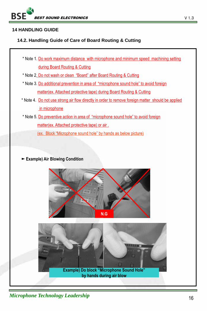
* Note 1. Do work maximum distance with microphone and minimum speed machining setting
during Board Routing & Cutting
* Note 2. Do not wash or clean “Board” after Board Routing & Cutting
* Note 3. Do additional prevention in area of “microphone sound hole” to avoid foreign
matter(ex. Attached protective tape) during Board Routing & Cutting
* Note 4. Do not use strong air flow directly in order to remove foreign matter should be applied
in microphone
* Note 5. Do preventive action in area of “microphone sound hole” to avoid foreign
matter(ex. Attached protective tape) or air .
(ex. Block “Microphone sound hole” by hands as below picture)
Example) Do block “Microphone Sound Hole”
by hands during air blow
Example) Air Blowing Condition
N.G
14.2. Handling Guide of Care of Board Routing & Cutting
14 HANDLING GUIDE
BEST SOUND ELECTRONICS
Microphone Technology Leadership
V 1.3
17
* Note 1. Do inspect X-Ray after SMD.
It is different X-Ray condition by applied SMD company.
14.3. Inspection by X-Ray
14 HANDLING GUIDE
BEST SOUND ELECTRONICS
Microphone Technology Leadership
V 1.3
15. REWORK
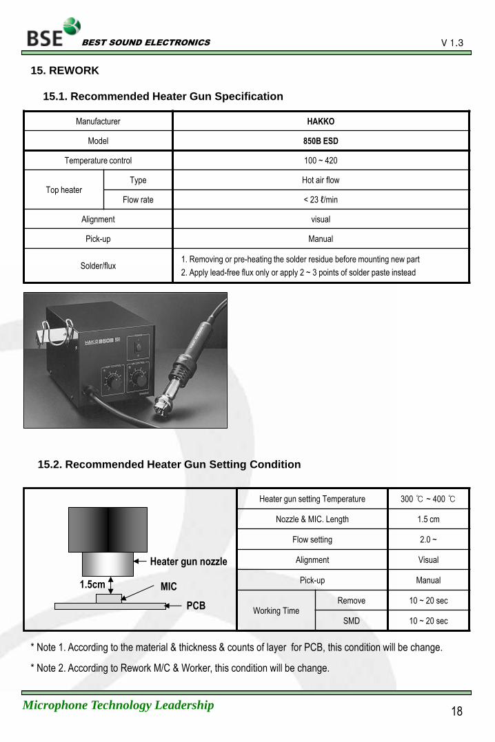
15.1. Recommended Heater Gun Specification
Manufacturer HAKKO
Model 850B ESD
Temperature control 100 ~ 420
Top heater Type Hot air flow
Flow rate < 23 ℓ/min
Alignment visual
Pick-up Manual
Solder/flux 1. Removing or pre-heating the solder residue before mounting new part
2. Apply lead-free flux only or apply 2 ~ 3 points of solder paste instead
1.5cm
Heater gun nozzle
MIC
PCB
15.2. Recommended Heater Gun Setting Condition
Heater gun setting Temperature 300 ~ 400
Nozzle & MIC. Length 1.5 cm
Flow setting 2.0 ~
Alignment Visual
Pick-up Manual
Working Time Remove 10 ~ 20 sec
SMD 10 ~ 20 sec
* Note 2. According to Rework M/C & Worker, this condition will be change.
* Note 1. According to the material & thickness & counts of layer for PCB, this condition will be change.
18
BEST SOUND ELECTRONICS
Microphone Technology Leadership
V 1.3
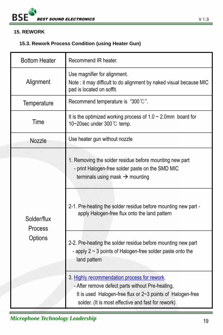
Bottom Heater Recommend IR heater.
Alignment
Use magnifier for alignment.
Note : it may difficult to do alignment by naked visual because MIC
pad is located on soffit.
Temperature Recommend temperature is “300”.
Time It is the optimized working process of 1.0 ~ 2.0mm board for
10~20sec under 300 temp.
Nozzle Use heater gun without nozzle
Solder/flux
Process
Options
1. Removing the solder residue before mounting new part
- print Halogen-free solder paste on the SMD MIC
terminals using mask mounting
2-1. Pre-heating the solder residue before mounting new part -
apply Halogen-free flux onto the land pattern
2-2. Pre-heating the solder residue before mounting new part
- apply 2 ~ 3 points of Halogen-free solder paste onto the
land pattern
3. Highly recommendation process for rework.
- After remove defect parts without Pre-heating,
It is used Halogen-free flux or 2~3 points of Halogen-free
solder. (It is most effective and fast for rework)
15.3. Rework Process Condition (using Heater Gun)
19
15. REWORK
BEST SOUND ELECTRONICS
Microphone Technology Leadership
V 1.3
* Note 1. Follow standard guide line of SMD company for Rework Condition
* Note 2. Rework conditions may variable by SMD companies' circumstance and working
condition.
* Note 3. Do Not reuse defect microphone by SMD process.
* Note 4. Do not employ chemical board wash or cleaning, as the associated cleaning
agents (such as liquid or air) can damage the device.
15.4. Handling of Rework
20
15. REWORK