Specification of a common platform for sensor-enabled RFID … · Building Radio frequency ID...
38
Building Radio frequency IDentification for the Global Environment Specification of a common platform for sensor-enabled RFID tags Authors: Antti Ruhanen (Confidex), Fabrizio Bertuccelli (CAEN) January 2008 This work has been partly funded by the European Commission contract No: IST-2005-033546
Transcript of Specification of a common platform for sensor-enabled RFID … · Building Radio frequency ID...

Building Radio frequency IDentification for the Global Environment
Specification of a common platform for sensor-enabled RFID tags
Authors: Antti Ruhanen (Confidex), Fabrizio Bertuccelli (CAEN)
January 2008 This work has been partly funded by the European Commission contract No: IST-2005-033546

About the BRIDGE Project: BRIDGE (Building Radio frequency IDentification for the Global Environment) is a 13 million Euro RFID project running over 3 years and partly funded (€7,5 million) by the European Union. The objective of the BRIDGE project is to research, develop and implement tools to enable the deployment of EPCglobal applications in Europe. Thirty interdisciplinary partners from 12 countries (Europe and Asia) are working together on : Hardware development, Serial Look-up Service, Serial-Level Supply Chain Control, Security; Anti-counterfeiting, Drug Pedigree, Supply Chain Management, Manufacturing Process, Reusable Asset Management, Products in Service, Item Level Tagging for non-food items as well as Dissemination tools, Education material and Policy recommendations. For more information on the BRIDGE project: www.bridge-project.eu This document results from work being done in the framework of the BRIDGE project. It does not represent an official deliverable formally approved by the European Commission. This document: As the use of the sensor enabled tags is not yet common, the purpose of this document is to provide some information about the importance of these devices and their possible use in real applications and, taking into account the work done on this matter by EPC and ISO, to illustrate a common platform of behaviour that can contribute to spread the adoption of sensor-enabled RFID tags even in complex open loop markets. Our approach is considering the development within ISO and EPC Global, but the scope is slightly narrower than those bodies propose. Also user requirements are derived from fictional use cases since real life use cases were not available. Focus is strictly on sensor functionality and some related problems like access control and battery support are omitted. However, this approach does not exclude those other features and - for example - access control and battery support can be easily applied parallel to sensor functionality.
Disclaimer: Copyright 2007 by (Confidex, CAEN) All rights reserved. The information in this document is proprietary to these BRIDGE consortium members This document contains preliminary information and is not subject to any license agreement or any other agreement as between with respect to the above referenced consortium members. This document contains only intended strategies, developments, and/or functionalities and is not intended to be binding on any of the above referenced consortium members (either jointly or severally) with respect to any particular course of business, product strategy, and/or development of the above referenced consortium members. To the maximum extent allowed under applicable law, the above referenced consortium members assume no responsibility for errors or omissions in this document. The above referenced consortium members do not warrant the accuracy or completeness of the information, text, graphics, links, or other items contained within this material. This document is provided without a warranty of any kind, either express or implied, including but not limited to the implied warranties of merchantability, satisfactory quality, fitness for a particular purpose, or non-infringement. No licence to any underlying IPR is granted or to be implied from any use or reliance on the information contained within or accessed through this document. The above referenced consortium members shall have no liability for damages of any kind including without limitation direct, special, indirect, or consequential damages that may result from the use of these materials. This limitation shall not apply in cases of intentional or gross negligence. Because some jurisdictions do not allow the exclusion or limitation of liability for consequential or incidental damages, the above limitation may not apply to you. The statutory liability for personal injury and defective products is not affected. The above referenced consortium members have no control over the information that you may access through the use of hot links contained in these materials and does not endorse your use of third-party Web pages nor provide any warranty whatsoever relating to third-party Web pages.

BRIDGE – Building Radio frequency IDentification solutions for the Global Environment
Table of Contents
1 INTRODUCTION ........................................................................................................................................ 4
1.1 RELATED STANDARDS .................................................................................................................................. 4
2 USE CASES FOR SENSOR ENABLED RFID TAGS ............................................................................. 7
2.1 COLD CHAIN MONITORING ............................................................................................................................ 7
2.1.1 Continuous temperature log ............................................................................................................. 8
2.1.2 Time - temperature integral only ..................................................................................................... 8
2.2 SHOCK DETECTION OF VALUABLE GOODS ................................................................................................... 9
2.3 CONDITION MONITORING IN MANUFACTURING ............................................................................................. 9
2.4 TAMPER PROOFING ...................................................................................................................................... 9
3 OPERATION MODES AND PARAMETERS .......................................................................................... 11
3.1 TIMING PARAMETERS ................................................................................................................................. 11
3.2 LOGGING MODES ........................................................................................................................................ 12
4 DESCRIPTION OF OPERATION ............................................................................................................ 13
4.1 SIGNALLING THE PRESENCE OF A SENSOR ................................................................................................ 13
4.2 DEFINING MEMORY AREAS FOR EACH SENSOR ......................................................................................... 14
4.3 HANDLING INDIVIDUAL SENSOR .................................................................................................................. 15
4.3.1 Memory map ..................................................................................................................................... 15
4.3.2 Sampling and configuration ............................................................................................................ 16
4.3.3 Data record ....................................................................................................................................... 18
4.3.4 Sensor reset ..................................................................................................................................... 19
5 ISO18000-6C COMPATIBLE SENSOR-ENABLED TAG ..................................................................... 19
5.1 USING SENSOR TAG WITH MEMORY ACCESS COMMANDS ......................................................................... 19
5.2 AIR INTERFACE EXTENSION FOR A SENSOR ENABLED TAG ........................................................................ 20
5.2.1 Data Record Type............................................................................................................................ 20
5.2.2 ReadNumberSensors (optional) .................................................................................................... 21
5.2.3 ReadSensorConfiguration (optional) ............................................................................................ 21
5.2.4 WriteSensorConfiguration (optional) ............................................................................................. 22
5.2.5 ReadSensorValue (optional) .......................................................................................................... 23
5.2.6 ReadSensorData (optional) ............................................................................................................ 23
5.2.7 EraseSensorData (optional) ........................................................................................................... 24
CONTINUOUS LOGGING MODE ......................................................................................................................... 30
ANOMALY LOGGING MODE ............................................................................................................................... 32
EVENT LOGGING -MODE ................................................................................................................................... 34

BRIDGE – Building Radio frequency IDentification solutions for the Global Environment
1 Introduction The use of Radio Frequency Identification (RFID) in the Ultra High Frequency band for the automatic identification of products is causing a revolution in many industrial sectors from the manufacturing level up to the distribution chain; in particular it is becoming a crucial factor for product’s cost reduction and quality assessment and a wide selection of passive tag is already available on the market. The main characteristic of this new technology is the possibility to quickly identify in the same inventory session a high number of items without the need of a proximity inspection as it were in the case of the barcode and HF technology. Sometimes the introduction of new technologies open new opportunities that were simply impossible before; in this case the wide adoption in the market of UHF RFID techniques has made possible the use of tags equipped with sensors whose aim is tracing those environmental parameters that can affect the life of a product; their employment can thus greatly contribute to product’s quality management. For the time being a very few types of sensor-enabled tags are commercially available and what’s more important each of them use proprietary protocols that make hard their effective use in complex chains typical of this period of global economy. One of the main UHF RFID standard adopted by passive tag is the EPC C1 GEN2 protocol defined by the EPC Global organization, one of the leader in the development of industry-driven standards in the field of product’s identification. This standard has also been adopted by ISO with the name of ISO18000-6C. To overcome interoperability problems that may arise from the use of proprietary protocols in
sensor-enabled tags, EPC global SB-JRG1 is now trying to collect and summarize the end-
user requirements for this new class of tags. ISO workgroups are in the same time working with air-interface extension to ISO 18000-6 standard and also on the application protocol ISO 24753: Encoding and processing rules for sensors and batteries. However these standards are not yet at consensus stage. As the use of the sensor enabled tags is not yet common, the purpose of this document is to provide some information about the importance of these devices and their possible use in real applications and, taking into account the work done on this matter by EPC and ISO, to illustrate a common platform of behaviour that can contribute to spread the adoption of sensor-enabled RFID tags even in complex open loop markets. Our approach is considering the development within ISO and EPC Global, but the scope is slightly narrower than those bodies propose. Also user requirements are derived from fictional use cases since real life use cases were not available. Focus is strictly on sensor functionality and some related problems like access control and battery support are omitted. However, this approach does not exclude those other features and - for example - access control and battery support can be easily applied parallel to sensor functionality.
1.1 Related standards In BRIDGE development and also in this document the focus is on UHF tags based on EPC Class1 Gen2. This same air interface is adopted by ISO into 18000-6C standard. ISO is keeping the data protocols and application standards separated from air interface standard. In this document, everything is mixed and things are handled in logical order from UHF semi-passive sensor enabled tag point of view. However, solutions could be divided to several layers and each layer could then be reused in another context. For example sensor handling means could be easily transferred to another air interface since the concept is not tied to particular air interface. One often used abstract model for communications and network protocols is OSI reference model. The OSI Model consists of the Application, Presentation, Session, Transport, Network, Data Link, and Physical layers. These seven basic layers provides a good basis for analysis and design of protocols although real life protocols may not fit clearly into the OSI
1 EPC Global - Joint Requirements Group - Sensors & Battery-Assist Passive Tag

BRIDGE – Building Radio frequency IDentification solutions for the Global Environment
model. Illustration 1 is trying to roughly outline the location of the most relevant existing and forthcoming standards related to sensor enabled RFID tags in OSI model.
RFID standards won't fit directly into OSI reference model and this is only trendsetting illustration. The development in BRIDGE-project (and the content of this document) is focused mostly on presentation and application layer. Some things are located even in transport layer, for example new command extension for ISO 18000-6C. Standards mentioned in illustration are listed in Table 1 with topics and statuses.
Table 1: Standards related to UHF sensor enabled RFID tag
Standard Topic Status
EN 302 208 Electromagnetic compatibility and Radio spectrum Matters (ERM): Radio Frequency Identification Equipment operating in the band 865 MHz to 868 MHz with power levels up to 2 W
Ratified
ISO 18000-6C Information technology - Radio frequency identification for item management - Part 6: Parameters for air interface communications at 860 MHz to 960 MHz - Amendment 1: Extension with Type C and update of Types A and B
Ratified. Amendments under preparation.
ISO 15961 Data protocol: application interface (four parts).
Ratified. Amendments under preparation.
ISO15962 Data protocol: data encoding rules and logical memory functions
Ratified. Amendments under preparation.
ISO 15963 Unique identification for RF tags. Ratified.
ISO 24753 Application protocol: encoding and processing rules for sensors and batteries.
Under preparation
Illustration 1: Standards related to UHF sensor tags and their location in OSI model

BRIDGE – Building Radio frequency IDentification solutions for the Global Environment
EPC Tag Protocol EPC Radio-Frequency Identity Protocols Class-1 Generation-2 UHF RFID Protocol for Communications at 860MHz – 960MHz Version 1.1.0
Ratified. Amendments under preparation.
EPC Tag Data Standard
EPC Tag Data Standards Version 1.3.1 Ratified.
As it is easy to notice, the standardization of sensor enabled RFID tags is still heavily under construction. In this document, one possible solution for sensor handling is presented while some essential problems are totally omitted (e.g., battery support, compatibility with other standards, limited use case coverage).
BRIDGE – Building Radio frequency IDentification solutions for the Global Environment
2 Use cases for sensor enabled RFID tags In recent years the concept of quality has risen of importance in various fields such as medical care, logistics, trade and equipment. Unfortunately, due to the intrinsic complexity of a typical supply chain, a company may produce high quality products but some people in the supply chain may not be aware of the sensitivity to some environmental parameters in the products they are handling. As a consequence the quality perceived by the end customer can be significantly different from the quality that was achieved by the manufacturer at the very beginning of the supply chain. This can result in a loss of trust in terms of the brand’s image and, in some extreme cases, can even affect heavily the end customer’s health. One of the actions that can be undertaken to monitor product’s quality degradation along the supply chain is the data-logging of different physical parameters (i.e., temperature, humidity, shock, etc.). The introduction of UHF RFID technology as one of the main instruments of the electronic identification of goods can in fact help manufacturers to monitor products while they are in transit along the supply chain. In particular a sensor-enabled RFID tag is the key components that can led to the introduction in the market of the Quality Oriented Tracking and Tracing (QTT) concept that is the ability to automatically identify goods combined with the capability of recording temperature, humidity, light and other environmental parameters that may have a great impact on the final quality of a product. In a first step the sensor-enabled RFID tag could be configured by the manufacturer to start recording a set of specific environmental variables. During transport or during its transit along the distribution chain, the sensor tag measures and stores the environmental variables inside a non volatile memory without the need of an external communication. When passing through a reader’s gate during loading/unloading activities, the measured data can be retrieved from the tag so that the evaluation of the product’s quality can be immediately assessed on the base of real measurements. Since RFID sensor tags communicate using wireless communication, data collection is facilitated because automatic data download becomes possible provided that the RFID tag is located within the RFID range of the RFID reader. The fact that each tag has an electronic code ID can also be used for environmental recording of individual items by combining acquired physical data with the identification function.
2.1 Cold chain monitoring The so-called cold chain refers to any supply chain of products that must be shipped under a set of prescribed temperature condition. Sometimes the conditions under which the product must be kept are mandated by governmental regulations; other times these conditions are determined and enforced internally by the manufacturer itself to maintain a high standard of quality. Typical examples of cold supply chains are the food and the bio-pharma supply chains. Food Supply chain: Food naturally goes into some sort of degradation which increases with time caused by: 1. Degradation of molecules 2. Fungal and bacterial contamination and growth in food. Both phenomena are heavily influenced by temperature so it is easy to understand that among environmental parameters, temperature has the most significant influence on the quality of food products. Another concept strictly related to quality in case of perishable goods is the shelf-life i.e. the time after which the food’s quality loss becomes unacceptable. Most companies restrict their view to compliance regulations, which offer only accept/reject decision based on overstepping of temperature thresholds but for high quality products the shelf-life can be even shorter than the mandated expiration date. A temperature log is often required to evaluate the real shelf-life of a product. Bio-pharma supply chain:

BRIDGE – Building Radio frequency IDentification solutions for the Global Environment
One of the leading sectors requiring a temperature controlled supply chain is the pharmaceutical sector particularly with the growth of temperature sensitive biological based drugs. A relevant part of the overall pharmaceutical products sold world wide is in fact constituted by biopharmaceutical products which are 100% temperature sensitive. If temperature is not maintained within an optimal range, the drug may be inactivated or in the worst case may harm the patient. The World Health Organization (WHO) for example has stated that as much as 25% of all vaccines products reach their destinations in a degraded state and in the USA the army has revealed that a quarter of shipments of anthrax vaccine were not maintained at average temperature within temperature range [1]. For that reason, in recent years, global regulatory agencies have increased oversight to ensure the integrity of pharmaceuticals products in the distribution chain. For instance, WHO and UNICEF have mandated that all oral polio vaccines must include a real time temperature monitoring [2] [3]. From another point of view many government regulations require that some valuable drugs expire after one year. Despite that many drugs, kept under optimal conditions, remain viable longer than expiration date. Significant economical benefits can be achieved if the product could be determined “fresh” even after its expiration date. Both these sectors well describe the need for a precise temperature control over time during the product lifetime, control that could be provided by a sensor-enabled RFID tag provided with a temperature sensor on-board.
2.1.1 Continuous temperature log
As said previously, the shelf-life of a product is a function of the temperature the good has been exposed to during the transit along the supply chain from the manufacturer to the end-customer. This means that even if products are stored at temperature according to the law, they might still loose quality quickly because temperature is not kept within optimal or recommended temperature range for this specific item. Beside technical details the precise modelling of shelf-life changes is usually a hard task as it depends heavily on the specific product type. One very common approach is to describe the quality decay according to the Arrhenius’s law for reaction kinetics. Another equation frequently used is the Mean Kinetic Temperature (MKT) which is regarded for example by the International Conference on Harmonization (ICH) as “a single derived temperature, which, if maintained over a defined period, would afford the same thermal challenge to a pharmaceutical product as would have been experienced over a range of both higher and lower temperatures for an equivalent defined period” [4]. In both cases the change in shelf life or loss per day is calculated as a function of temperature. But in many food products, the complexity of the reaction involved in the degradation processes make the approximation introduced by the use of the Arrhenius function or by the MKT not always suitable for the required accuracy [5]. If we want avoid the use at the tag level of empirical models validated for each specific product, the temperature time function has therefore to be continuously monitored. The drawbacks of this operating mode are: 1. The large amount of non volatile memory that is required to save all temperature samples. 2. The time required to retrieve this data from temperature tags. In a real application both the combined use of predefined equations and continuous temperature logging could help in evaluating the real shelf-life of perishable products. The MKT and Arrhenius formula could be used for example to quickly evaluate if the good under examination has been exposed to non optimal temperature conditions; a more accurate exam can then be undertaken in a second time using all temperature samples when the embedded functions signal that a user selected threshold has been overrun.
2.1.2 Time - temperature integral only
Another way to evaluate the abuse of temperature in the production, transportation and storage of temperature sensitive products is to monitor temperature only in occurrence of out-of limit conditions. This mode of operation is suggested by many country regulations in terms of food and pharmaceutical products: restrictions about storage temperature conditions

BRIDGE – Building Radio frequency IDentification solutions for the Global Environment
which a specific product may undergo during its lifetime are usually reported in a tabular form with the indication of the maximum and minimum allowed temperature. In this mode of operation the user is allowed to define maximum and minimum temperature threshold limits: when this values are overrun data logging is started, when temperature returns within the normal sample acquisition is stopped. Though the information available is less than the one available in the continuous temperature log, usually this mode requires a reduced amount of memory to store data samples with the advantage that the continuous sample waveform acquired outside of thresholds may still be used for a good estimation of the life-shelf reduction.
2.2 Shock detection of valuable goods Temperature is not the only environmental parameters that it is worth monitoring along the distribution chain. In some cases, especially for valuable goods, the sensitivity is related more to the handling conditions, which expose the product to risk of damage or malfunctioning, than to spoilage due to temperature abuse. Among the others, in particular the following valuable goods: - Avionics products - Sensitive computers or electronic devices - Aerospace components - Military equipments - Ammunition may require the use of sensor-enabled tags equipped with shock sensors to guarantee product’s integrity. Improper handling events such as impacts, drops, inclination and flipping can inadvertently occur not only during shipping but also during the storage phase. Again, the use of a UHF RFID shock-enabled tag allows the review of the shipping and handling log contextually with standard inventory operation and contributes to the control of product’s integrity without the need of a direct inspection.
2.3 Condition monitoring in manufacturing RFID tags are also widely used in manufacturing plants for WPI (Work In Progress) applications. Individual intermediate products or transport units are tagged with RFID tags and movements of these items are monitored with RFID readers in desired reading points. This gives a lot more visibility to production and enables companies to optimize their operations. When intermediate storages can be reduced, throughput will increase and also some bound up capital is liberated. Tags used in these applications may be disposable or the lifetime requirement might be up to several years. In some cases intermediate products will need to go through various maturation phases (for example curing, drying or ageing). The duration of this maturation process is dependent on (for example) temperature and humidity. With a sensor enabled RFID tag these parameters could be monitored item by item and by doing so the holding times may be reduced and overall stock holding as well. Further a reduction in energy usage may also been achievable. In this case, a sensor enabled tag shall measure and store the sensor data with the desired interval. Tag can be read automatically with reader network covering whole space or periodically with hand-held RFID reader. Decision of completion can be made either by back-end-system (based on sensor data) or even by the tag itself (if enough “smartness” is coded into tag).
2.4 Tamper proofing Tamper proofing refers to methods used for hinder, deter and/or detect unauthorized access to a sealed system. RFID tags can be used as e-seals, which can be read automatically at desired control points. Mechanical structure of the tag can provide means for hinder tampering while electrical functionality provides tamper-evident. At the same time the e-seal can incorporate the unique ID of item (for example transport item). This is yet another use case for a sensor enabled RFID tag. In this case the sensor is basically one bit sensor (on/off). If an RFID tag is equipped with a battery (i.e., semi-passive or active tag), it can

BRIDGE – Building Radio frequency IDentification solutions for the Global Environment
record a timestamp of tampering. This will help to determine the liability questions in case of tampering. In simplest case, a sensor enabled RFID tag shall provide a tamper-evident at reading point without any other related information. This can be done even with fully passive tag. More complex case would be multi-sensor case (several tamper monitoring points) with timestamp logging capability. This requires a battery supported tag.

BRIDGE – Building Radio frequency IDentification solutions for the Global Environment
3 Operation modes and parameters To find out a universal and comprehensive set of requirements for sensor-enabled tags is extremely challenging task. The use cases presented in Chapter 2 are just few examples where sensor enabled RFID tags can be used. However, we believe that majority of future applications will have similar characteristics compared to these use cases. Operation modes and parameters presented in this chapter are designed to fulfil the requirements of the example use cases shown in Chapter 2.
3.1 Timing parameters This timing parameter scheme is created to fulfil the requirements of use cases presented in chapter 2. Our approach is to have synchronous system without need of asynchronous operations (externally triggered operations). This does not bind the implementation of the sensor enabled tag. Synchronous operations means that logged time values are quantized with the pre-desired resolution. Resolution can be adjusted to meet the requirements of the specific application. In many cases, this is the most energy-efficient way to implement a tag and thus to achieve a maximal lifetime. On the other hand if a tag implements the asynchronous operations it is relatively easy to do the quantization in a tag and thus behave like this document is describing. There is only one user definable timing parameter: Interval. The interval is a 16bit unsigned integer value representing seconds. This is a time interval, how often the value of the sensor is measured (i.e., resolution). The measurement does not perform any log of itself. After the measurement, the tag shall evaluate the need of logging. This depends on the operation mode and LIMIT-registers. These concepts are presented later. Some example values of INTERVAL-register are presented in Table 2 to clarify the meaning
Table 2: Example values of INTERVAL register
INTERVAL-register Meaning
dec hex
0 0000 Illegal value
1 0001 1 second
10 000A 10 seconds
600 0258 10 minutes
65535 FFFF 18h 12min 15s
Another user definable timing register is STARTTIME. It is not actually a control register. It is just a memory slot to store the starting time of logging (Unix timestamp representation). The tag is not required to validate it at all (real time clock is not required in tag). Some example values are presented in Table 3. Most of the programming languages supports directly UNIX timestamp format.

BRIDGE – Building Radio frequency IDentification solutions for the Global Environment
Table 3: Example values of TIMESTAMP register
TIMESTAMP-register Meaning
dec hex
0 0000 0000 January 1, 1970 (midnight UTC/GMT)
1197396494 475E D20E December 11, 2007 (18:08:14 UTC/GMT)
-2147483648 8000 0000 December 13, 1901 (20:45:52 UTC/GMT)
2147483 647 7FFF FFFF January 19, 2038 (03:14:07 UTC/GMT)
3.2 Logging modes A logging configuration scheme is created to fulfil the requirements of example use cases presented in chapter 2. The Scheme is relatively simple but still flexible enough to meet the requirements of various use cases. The logging behaviour is mainly controlled with single 16bit-register. This register is called LOGCTRL-register. A bit wise content of register is presented at the chapter 4. There are basically three operating modes. Logging can be also turned off. These modes are not directly switched on by choosing one, but are the results of different sensible combinations of operating parameters. Logging off -mode: The tag is working as a normal ISO18000-6C tag. Previous logging results are readable from memory. Continuous logging -mode: The tag is continuously logging the measured value with an interval defined by the INTERVAL-register. Only measured data is saved into the memory. The threshold monitoring can be also switched on, if desired. In that case, violation of predefined limits will raise an alert so it can be discovered quickly without reading the whole logged memory. Anomaly logging -mode: The tag is continuously measuring the sensor value with the interval defined by the INTERVAL-register. If this value is violating either the lower or the higher limit, the value will be logged with the corresponding time index. Real time of this event can be calculated later from time index, interval and start time. Event logging -mode: The tag is continuously measuring a sensor value with the interval defined by INTERVAL-register. If measured value is violating either lower or higher limit, the corresponding measurement index will be logged. Real time of this even can be calculated later from this index, interval and start time. Data itself is not logged. This is particularly useful when certain threshold is under observation. This event will raise an alert which can be read quickly at the control point. Note that some of the sensor types will require an asynchronous operation (such as shock sensor). However, a tag will record an event only with the resolution defined in INTERVAL-register. Note that these modes are only conceptual and doesn't appear similarly in configuration registers. Modes are presented here to clarify the capabilities of semi-passive sensor enabled RFID tag.
BRIDGE – Building Radio frequency IDentification solutions for the Global Environment
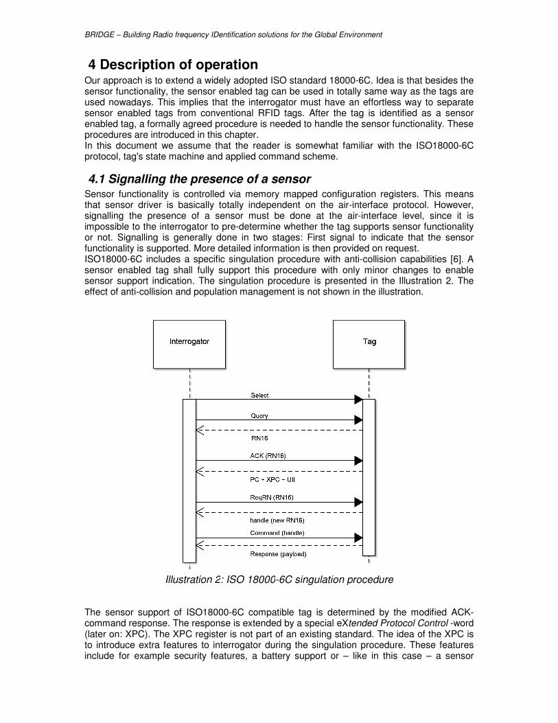
4 Description of operation Our approach is to extend a widely adopted ISO standard 18000-6C. Idea is that besides the sensor functionality, the sensor enabled tag can be used in totally same way as the tags are used nowadays. This implies that the interrogator must have an effortless way to separate sensor enabled tags from conventional RFID tags. After the tag is identified as a sensor enabled tag, a formally agreed procedure is needed to handle the sensor functionality. These procedures are introduced in this chapter. In this document we assume that the reader is somewhat familiar with the ISO18000-6C protocol, tag's state machine and applied command scheme.
4.1 Signalling the presence of a sensor Sensor functionality is controlled via memory mapped configuration registers. This means that sensor driver is basically totally independent on the air-interface protocol. However, signalling the presence of a sensor must be done at the air-interface level, since it is impossible to the interrogator to pre-determine whether the tag supports sensor functionality or not. Signalling is generally done in two stages: First signal to indicate that the sensor functionality is supported. More detailed information is then provided on request. ISO18000-6C includes a specific singulation procedure with anti-collision capabilities [6]. A sensor enabled tag shall fully support this procedure with only minor changes to enable sensor support indication. The singulation procedure is presented in the Illustration 2. The effect of anti-collision and population management is not shown in the illustration.
The sensor support of ISO18000-6C compatible tag is determined by the modified ACK-command response. The response is extended by a special eXtended Protocol Control -word (later on: XPC). The XPC register is not part of an existing standard. The idea of the XPC is to introduce extra features to interrogator during the singulation procedure. These features include for example security features, a battery support or – like in this case – a sensor
Illustration 2: ISO 18000-6C singulation procedure

BRIDGE – Building Radio frequency IDentification solutions for the Global Environment
support. Existing tags (without XPC) will be totally compatible with this amendment. The needed changes to the interrogators can be done with firmware update.
Table 4: Modified response to ACK-command
Response
# of bits 37 to 528
Description PC + XPC + UII + CRC16
Presence of the XPC-register is indicated with a single bit in the PC-register (Protocol Control) which is transferred before XPC in ACK-response. Content of the PC-register is presented in Illustration 3. Bit X is zero in conventional tags and one in sensor enabled RFID tags. After receiving bit one, the interrogator is waiting for the XPC register after the PC-register.
Fully functional sensor support (as described in this document) is indicated in XPC-register with FS-bit. After this initial indication of the sensor support, an interrogator shall read the Sensor address Map (SAM) address from TID memory at memory word 20h MSB first. This SAM address is basically a pointer to SAM which then can be stored anywhere in memory space. Structure of this SAM pointer is presented in table 5.
Table 5: Structure of SAM pointer
RFU MB Address
# of bits 6 2 24
Description Reserved for future use
Memory bank selector
SAM Address
SAM pointer allows access to the Sensor Address Map (SAM), which includes the information about the amount of sensors and allocated memory areas for each sensor.
4.2 Defining memory areas for each sensor SAM pointer allows interrogator to find a Sensor Address Map. The Sensor Address Map contains the information about amount of sensors and memory area definitions for each sensor. The number of available sensors (NoS) is stored into SAM first followed by SAM entries for each sensor. NoS is stored as 16bit unsigned integer value. Each SAM entry contains a
Illustration 3: Content of PC and XPC registers

BRIDGE – Building Radio frequency IDentification solutions for the Global Environment
pointer to the beginning of the allocated memory and memory range for that specific sensor. All information related to this sensor is in that range including the configuration, status and data registers. Structure of SAM entry is presented in the Table 6.
Table 6: Structure of SAM entry
RFU MB Address Range
# of bits 6 2 24 16
Description Reserved for future use
Memory bank selector
Sensor address
Memory range
Each sensor has own SAM entry in the Sensor Address Map. This link chain is clarified in Illustration 4. Illustration is an example of two available sensors in a one tag. The user memory bank can be one linear memory space even though it is presented as two separated area in illustration.
After this procedure the interrogator is capable to handle each individual sensor with means described later in this document. Even though the focus of this document is to extend ISO18000-6C -protocol, the sensor handling means after this point are totally independent from air interface protocol. This means that the same approach can be applied for example to any ISO18000-series protocols.
4.3 Handling individual sensor Usage of an individual sensor is based on memory mapped registers. These registers can be handled with normal read and write operations provided by the air interface protocol. It is also possible to define special commands for sensor handling like done in chapter 5. However, these two methods are totally congruent and they both can be used to modify and read the register values.
Like said, the sensor behaviour is totally independent from the air interface and is based only on the values of configuration registers. These registers are presented and described in this section.
4.3.1 Memory map
To make it possible for an interrogator to handle the sensor data, the register allocation has to be well defined and standardized. The overall allocation of memory and location of different registers are presented in Illustration 5.
Illustration 4: Example chain of pointers

BRIDGE – Building Radio frequency IDentification solutions for the Global Environment
LOGSTAT -register is a read-only register containing the status flags (memory full, upper limit violation and lower limit violation -flags) and the information about data type of this specific sensor. LOGCTRL register is the main configuration register. The behaviour of the sensor is mainly dependent on this register. Also resetting of sensor is done through one specific bit of this register. STARTTIME register is the starting time of current log. Format of this register is UNIX time stamp -format (as presented in chapter 3). The register can be written only when logging is not ongoing. Content of the register is totally dependent on the user since tag is not required to validate the values. COUNT register is the amount of logged data records. It is a read-only register. INTERVAL register is the measuring interval of this sensor in seconds. This register can be written only when logging is turned off. LIMIT_LO and LIMIT_HI registers defines the allowed (or normal) range of sensor value. Sensor can be configured to monitor that sensor value is between these limits. Size and type of these registers are the same as data type and size (defined in LOG_STAT -register).
4.3.2 Sampling and configuration
Configuration is basically a three step procedure:
1. Read the status and data type of the tag
2. Write interval, start time and limit registers
3. Write LOGCTRL register with desired configuration and reset-bit as true. This procedure is needed to prevent data corrupting. Data type (mainly the size) is needed for writing the correct limit values. These limit values together with interval time has to be written before logging is started. It is recommended to write start time just before resetting the tag.
4.3.2.1 LOGCTRL -register The configuration is mainly done with LOGCTRL-register. Register content is shown in Illustration 6.
Illustration 5: Sensor memory allocation

BRIDGE – Building Radio frequency IDentification solutions for the Global Environment
RST-bit is always read as zero. This bit has to be set when starting the new log. After tag receives a new configuration record with RST-bit activated it will reset the COUNT-register and do all the necessary preparations for a new log. L-bit is used to control the sensor monitoring. If this bit is zero, the actual sensor value is never read. This bit turns on the system. If bit is activated, the sensor value is measured with interval defined in the INTERVAL -register. Logging decision is done after the measurement and it is dependent on rest of the configuration. D-bit is used to define if the sensor value is stored into the memory in case of data record is created. In most cases this bit needs to be set. If stamp of specific event is the only concern, this bit can be cleared. TL-bit is used to define if the time index is stored into the memory when data record is created. Time index is a value of elapsed intervals by the time the data record was created. M-bit is for operating mode. Zero means continuous logging. Data record is created and logged always when sensor value is read (defined by INTERVAL-register). Bit one means that the data record is created and logged only when the limits are violated (and limit monitoring is turned on) LHM- and LLM-bits are used turn on the limit monitoring. This can be done even in continuous logging mode. In this case the limit violation flags in LOGSTAT register are raised during logging (if limits are violated). It is fast to check the flags to determine if the limits have been violated without need to read the whole memory.
4.3.2.2 LOGSTAT -register LOGSTAT -register is used determine the status of the tag and minimal characteristics to be able to handle the sensor related data. Register content is shown in Illustration 7. Register is a read-only register.
Illustration 6: Description of LOGCTRL-register

BRIDGE – Building Radio frequency IDentification solutions for the Global Environment
TYPE-field tells to interrogator the data type and length of actual measurement results. This is needed for proper handling and storing of the downloaded data. All the other sensor characteristics must be stored in back-end system. Reader systems without proper knowledge of sensor characteristics are still capable to read out and store the data. F-bit is raised by the tag when logging is on but the memory is full. LLV- and LHV -bits are used as flags of limit violations. Flags are cleared automatically when tag is reset.
4.3.2.3 Other configuration registers STARTTIME -register is a UNIX time representation of the time when logging was started. The tag is not required to validate this value so the reliability is only dependent on the user. However, the starting time is often very important to know. Calculating the real time of logged data records is based on this time stamp. COUNT is a read-only register having the amount of data records in the memory. This register is incremented by the tag every time when a data record is stored to memory. Count is cleared by the tag during the reset. INTERVAL -register is used to define the measurement interval of this sensor. At the same time it is the resolution of logging feature. In some cases the nature of measured quantity (e.g., shock sensor) demands more frequent sensor reading. In this case the INTERVAL-register will still define the logging interval and resolution (i.e., time precision) for the system. LIMIT_LO and LIMIT_HI -registers are used similarly to define the lower limit and the upper limit respectively. Data type is the same as for the measurements results (defined in LOGSTAT-register).
4.3.3 Data record
Data record is composed of a time index and a sensor value. Both are not required so one record can also be either of these alone. The data record composition is defined with LOGCTRL -register. Few possible combinations are presented in Table 7.
Illustration 7: Description of LOGSTAT-register

BRIDGE – Building Radio frequency IDentification solutions for the Global Environment
Table 7: Example data record combinations
Data type D-bit TL-bit Data record Length
0000 1 0 16bit signed integer 16 bits
0011 1 0 32bit unsigned integer 32 bits
0000 1 1 16bit signed integer + time index 32 bits
0000 0 1 time index 16 bits
Time index is the amount of time units elapsed since logging was started. Time unit is defined in INTERVAL-register. This means that real time of event can be calculated: real time = STARTTIME + (time index * time unit) Sensor value type is defined by sensor manufacturer and it is stored in LOGSTAT-register.
4.3.4 Sensor reset
Sensor reset is done simple by writing reset-bit in LOGCTRL -register. However, some things need to be considered to prevent data corrupting during logging session.
� RST-bit from LOGCTRL -register is always read as zero.
� After the reset, tag will clear status flags and count register.
� Other configuration registers has to be written before L-bit is set from LOGCTRL-register. These registers (LIMIT_LO, LIMIT_HI, STARTIME and INTERVAL) are read-only registers while logging session is ongoing.
� After the initialization, tag will perform the first measurement and store the data record (in event-mode, data record is stored only if limits are violated). Thus the first measurement is always done right after the reset regardless the value of the INTERVAL-register.
� When user wants to stop logging without losing the data, the LOGCTRL register has to be written again with the same configuration except L-bit (i.e., read register and write it back with modified L-bit)
This procedure ensures that tag data is not corrupted at any stage of logging.
5 ISO18000-6C compatible sensor-enabled tag As sensor’s management is based on the memory mapped registers, it is possible to drive a specific sensor by means of normal read and write operations provided by the ISO18000-6C protocol; alternatively it is possible to imagine a set of custom commands which extends protocol capabilities that are specific for sensor handling.
These two methods are totally congruent and both of them can be used to access sensor’s registers. First method is presented in paragraph 5.1; the second approach will be the object of paragraph 5.2. Note that both of these command-sets belong to access-commands group [6]. This means that user has to get through the access control before issuing these commands. Existing access control in ISO18000-6C includes password scheme, but sensor enabled tag can support as well the additional security layer developed in BRIDGE WP4.
5.1 Using sensor tag with memory access commands This paragraph describes how a sensor-enabled tag, whose memory allocation follow the structure defined in Chapter 4, can be accessed using the standard ISO18000-6C air interface protocol. As all sensor’s registers are mapped into tag’s memory, the availability of simple memory write and read operations is the minimum condition required to drive sensors and exercise their functionality. If we refer to the ISO18000-6C protocol, the memory access commands which are relevant for sensor management are Read, Write and BlockWrite (when available).

BRIDGE – Building Radio frequency IDentification solutions for the Global Environment
Using the EPC C1G2 protocol features it is also possible to lock the memory bank where sensors are mapped so that their access is granted only to trusted interrogators. For example if the SAM and the sensor’s memory area are both located in the EPC user memory, writing operation to this area could be regulated by the use of the Lock command; if the tag has non-null access password the user memory could be protected against unauthorized writing access (i.e., to people who do not know the access password) leaving at the same time the read operation open to everyone. In this way getting information from a sensor–enabled tag is a non privileged operation, while its configuration is reserved to a small trusted group. Another useful option could be to store the SAM in the EPC C1G2 Reserved memory (which can be locked as unreadable from the open state) and the sensor’s memory area in the EPC C1G2 user memory (which can be configured as write protected from the open state). In this case read and write access to SAM is password protected; as the SAM contains information about the sensor’s memory area, it could be hard for anyone who do not know the password even to retrieve information about sensor’s configuration and logged data. An example of sensor management using standard memory access commands is illustrated in Annex A.
5.2 Air interface extension for a sensor enabled tag The introduction of sensor enabled tags with its peculiar identification scheme and memory allocation tables suggests the needs for an extension of the EPC C1G2 protocol to increase sensor manageability. The aim is to consider the sensor enabled tag as an “abstract sensor device” on which it is possible to perform “abstract operation” like configuring the sensor, starting sampling operation and retrieving sampled data.
5.2.1 Data Record Type
Commands working on samples acquired from sensors refer to the Data Record Type as the smallest piece of information than can be stored in memory during one sample operation. The Data Record type is not fixed but depends on the sensor physical characteristic as well as on its configuration; in particular it depends from the Type field in the LOGSTAT register and from the D and TL fields on the LOGCTRL register. If for example a sensor has a resolution of 16 bit and its dynamic range goes from negative to positive values (Type filed = 0h) and the tag is configured in the anomaly logging mode (D = 1, TL = 1) the Data Record Type is composed by a 16 bit sample and by a 16 bit INTERVAL for a total length of 32 bit. The ReadSensorValue and ReadSensorData commands (more detailed presentation in paragraphs 5.2.5 and 5.2.6) use a special field, called DRT, to inform the tag about the expected type of records in the requested data collection. Tag will reply an error code if expected record type does not match with records stored in memory of the tag. This prevents misinterpretations. The DRT structure is illustrated in table 8.
Table 8: DRT Definition
Bit # 7 6 5..2 1 0
RFU RFU
Type D L
What follow describes a set of optional sensor access commands which allows an interrogator to read and write sensor specific data without requiring any additional knowledge about the underneath data structure. Even if our main concern has been to follow as closest as possible the ISO15961 specification some differences from that standard may be present in the extended commands described herein.

BRIDGE – Building Radio frequency IDentification solutions for the Global Environment
5.2.2 ReadNumberSensors (optional)
The ReadNumberSensors command allows an interrogator to determine the number of sensors attached to a tag. ReadNumberSensors includes the tag’s handle and a CRC16. The CRC16 is calculated over the first command code bit to the last handle bit. If a tag receives a ReadNumberSensors with a valid CRC16 but an invalid handle is shall ignore the command and remain in its current state (open or secured as appropriate). A ReadNumberSensors shall be pre-pended with a frame-sync. Table 9: ReadNumberSensors command
Command RN CRC16
# of bits 16 16 16
Description E0CAh handle Tag replies to a ReadNumberSensors returning the NoS word contained in the SAM table as shown in table 10.
Table 10: Tag reply to a ReadNumberSensors command
NoS RN CRC16
# of bits 8 16 16
Description Number of sensors handle
5.2.3 ReadSensorConfiguration (optional)
Interrogator and tags may implement the ReadSensorConfiguration command. ReadSensorConfiguration command allows an interrogator to request the configuration registers (LOGSTAT, LOGCTRL, STARTTIME, COUNT, INTERVAL, LIMIT_LO, LIMIT_HI) for each sensor attached to a tag. ReadSensorConfiguration has the following fields:
1. PortNr: relative ID of a specific sensor (from 1 up to NoS).
2. WordPtr: specifies the word address inside the configuration record, where words are 16 bits in length. For example WordPtr = 00h specify the LOGSTAT register, WordPtr = 01h specify the LOGCTRL register, etc.
3. WordCnt: specifies the number of words inside the configuration record to be read. If WordCnt = 01h the tag shall read a single data word.
The ReadSensorConfiguration additionally includes the tag’s handle and a CRC16. The CRC16 is calculated over the first command code bit to the last handle bit. If a tag receives a ReadSensorConfiguration with a valid CRC16 but an invalid handle or with a PortNr equal to 0 it shall ignore the command and remain in its current state (open or secured as appropriate).
Table 11: ReadSensorConfiguration command
Command PortNr WordPtr WordCnt RN CRC16
# of bits 16 8 16 16 16 16
Description E0CCh Logical sensor ID
Address Pointer
Number of words to be read
handle
Tag’s reply to a ReadSensorConfiguration command is reported in table 12. Table 12: Tag reply to a ReadSensorConfiguration command
Header Data RN CRC16
# of bits 1 Variable 16 16

BRIDGE – Building Radio frequency IDentification solutions for the Global Environment
Description 02 Configuration words handle
5.2.4 WriteSensorConfiguration (optional)
Interrogators and tags may implement the WriteSensorConfiguration command shown in table 13. The WriteSensorConfiguration allows an Interrogator to byte wise write the sensor configuration record for each sensor attached to a tag. WriteSensorConfiguration has the following fields:
1. PortNr: relative ID of a specific sensor (from 1 up to NoS).
2. WordPtr: specifies the word address inside the configuration record, where words are 16 bits in length. For example WordPtr = 00h specify the LOGSTAT register, WordPtr = 01h specify the LOGCTRL register, etc.
3. WordCnt: specifies the number of words inside the configuration record to be written. If WordCnt = 01h the tag shall write a single data word.
4. Data: contains the 16 bit words to be written and shall be 16 x WordCount bits in length.
The WriteSensorConfiguration command additionally includes the tag’s handle and a CRC16. The CRC16 is calculated over the first command code bit to the last handle bit. A WriteSensorConfiguration shall be prepended with a frame-sync. An interrogator may observe several possible outcomes from a WriteSensorConfiguration, depending on the success or failure of the tag’s memory write operation. The WriteSensorConfiguration succeeds: After completing the tag shall backscatter the reply shown in 14, comprising a header (a 0 bit), the tag’s handle and a CRC16 calculated over the 0-bit and handle. If the interrogators observe this reply within 20 ms then the WriteSensorConfiguration completed successfully.
The tag encounters an error: the tag shall backscatter an error code within 20 ms rather than the reply shown in table 14.
The WriteSensorConfiguration does not succeed: if the interrogator does not observe a reply within 20 ms then the WriteSensorConfiguration did not complete successfully. Upon receiving a valid WriteSensorConfiguration command a tag shall write the commanded configuration record or a part thereof into memory. The tag’s reply to a WriteSensorConfiguration shall use the extended preamble (i.e., a tag shall reply as if TRext =1 regardless of the Trext value in the Query that initiated the round). Table 13: WriteSensorConfiguration command
Command PortNr WordPtr
WordCnt Data RN CRC16
# of bits 16 8 16 16 Variable 16 16
Description E0CDh Logical sensor ID
Address Pointer
Number of words to be written
Configuration words
handle
Table 14: Tag reply to a WriteSensorConfiguration command
Header RN CRC16
# of bits 1 16 16
Description 02 handle

BRIDGE – Building Radio frequency IDentification solutions for the Global Environment
5.2.5 ReadSensorValue (optional)
Interrogators and tags may implement a ReadSensorValue command shown in table 15. ReadSensorValue allows an interrogator to request the current sensor value for each sensor attached to a tag. ReadSensorValue has the following fields:
1. PortNr: relative ID of a specific sensor (from 1 up to NoS).
2. DRType: should be equal to the Data Record Type as defined in paragraph 5.2.1. If the DRType value does not match the current Data Record Type for the sensor addressed by PortNr the tag shall ignore the command and remain in its current state (open or secured as appropriate).
The ReadSensorValue command additionally includes the tag’s handle and a CRC16. The CRC16 is calculated over the first command code bit to the last handle bit. A ReadSensorValue command shall be pre-pended with a frame-sync. The Data field length in the tag’s reply shall be equal to RecordSize x 16 bits where RecordSize is equal to the length in bits of the data record type addressed by the DRType parameter. For example if DRType = 00h RecordSize = 16, if DRType = 03h RecordSize = 32, etc. Table 15: ReadSensorValue command
Command PortNr DRType RN CRC16
# of bits 16 8 8 16 16
Description E0D2h Logical sensor ID
Data Record’s Type
handle
Table 16: Tag reply to a ReadSensorValue command
Header Data RN CRC16
# of bits 1 Variable 16 16
Description 02 Data Record handle
5.2.6 ReadSensorData (optional)
Interrogators and tags may implement the ReadSensorData command shown in table 17. ReadSensorData allows an interrogator to request a number of sensors data samples for each sensor attached to a tag. ReadSensorData has the following fields:
1. PortNr: relative ID of a specific sensor (from 1 up to NoS).
2. DRType: should be equal to the Data Record Type as defined in paragraph 5.2.1. If the DRType value does not match the current Data Record Type for the sensor addressed by PortNr the tag shall ignore the command and remain in its current state (open or secured as appropriate).
3. RecordPtr: specifies the data record inside the sensor’s data memory. For example RecordPtr = 00h specify the first data record, RecordPtr = 01h the second record, etc.
4. RecordCnt: Record sample. If RecordCnt = 00h the tag shall ignore the command and remain in its current state (open or secured as appropriate).
The ReadSensorData command additionally includes the tag’s handle and a CRC16. The CRC16 is calculated over the first command code bit to the last handle bit. An interrogator may observe several possible outcomes from ReadSensorData, depending on success or failure of the tag’s memory-access operation:

BRIDGE – Building Radio frequency IDentification solutions for the Global Environment
The ReadSensorData succeeds: After completing the tag shall backscatter the reply shown in table 18, comprising a header (a 0 bit), the requested sensor data records, the tag’s handle and a CRC16 calculated over the 0-bit to the last handle bit. The format of a data record can be determined from the DRType parameter. The tag encounters an error: The tag shall backscatter an error code rather than the reply shown in table 18.
Table 17: ReadSensorData command
Command PortNr DRType RecordPtr RecordCnt RN CRC16
# of bits 16 8 8 16 16 16 16
Description E0D0h Logical sensor ID
Data Record’s Type
Address Pointer
Number of data records to be read
handle
Table 18: Tag reply to a ReadSensorData command
Header Data RN CRC16
# of bits 1 Variable 16 16
Description 02 DataRecords handle
5.2.7 EraseSensorData (optional)
Interrogators and tags may implement the EraseSensorData command shown in table 19. EraseSensorData allows an interrogator to erase all sensors data records for each sensor attached to a tag. EraseSensorData has the following field:
1. PortNr: relative ID of a specific sensor (from 1 up to NoS). The EraseSensorData command additionally includes the tag’s handle and a CRC16. The CRC16 is calculated over the first command code bit to the last handle bit. An EraseSensorData command shall be pre-pended with a frame-sync. An interrogator may observe several possible outcomes from an EraseSensorData, depending on the success or failure of the tag’s memory erase operation. The EraseSensorData succeeds: After completing the tag shall backscatter the reply shown in table 20, comprising a header (a 0 bit), the tag’s handle and a CRC16 calculated over the 0-bit and handle. If the interrogators observe this reply within 20 ms then the WriteSensorData completed successfully. The tag encounters an error: The tag shall backscatter an error code within 20 ms rather than the reply shown in table 20.
The EraseSensorData does not succeed: If the interrogator does not observe a reply within 20 ms then the WriteSensorData did not complete successfully.
Upon receiving a valid EraseSensorData command a tag shall erase all sensor data records for the specified sensor. The tag’s reply to a WriteSensorConfiguration shall use the extended preamble (i.e., a tag shall reply as if TRext =1 regardless of the Trext value in the Query that initiated the round).
Table 19: EraseSensorData command
Command PortNr RN CRC16
# of bits 16 8 16 16
Description E0D1h Logical sensor ID handle Table 20: Tag reply to a ReadSensorData command
Header RN CRC16
# of bits 1 16 16

BRIDGE – Building Radio frequency IDentification solutions for the Global Environment
Description 02 handle

BRIDGE – Building Radio frequency IDentification solutions for the Global Environment
References
[1] GAO (United States General Accounting Office) -01-21: Serious Problems in the Anthrax Vaccine Immunization Program.
[2] WHO/V&B/99.18: WHO-UNICEF policy statement on the use of vaccine vial monitors in immunization services.
[3] WHO/V&B/00.14 Making use of Vaccine Vial Monitors.
[4] ICH Harmonised Tripartite Guideline Stability Testing of new drug substances and products step 4 version 06/02/2003
[5] Shelf-life estimation from accelerated storage data. Maria G. Corradini and Micha Peleg
[6] ISO/IEC18000-6:2004/Amd1:2006 Extension with Type C and update of Types A and B

BRIDGE – Building Radio frequency IDentification solutions for the Global Environment
Annex A: Example of sensor access using standard memory access commands
We assume that the tag has already been identified as a sensor-enabled tag by the interrogator during the anti-collision phase and that the Sensor Address Map and sensor memory areas are all stored in the EPC C1G2 User memory. To access the SAM memory area we need first to know its address in the User Memory. This information is contained in the SAM Pointer stored inside the TID memory. The command to issue is the following: Tag replies with the SAM Pointer (see the example below):
In the above reply the SAM memory is mapped in the User memory (MB : 112) at address 60h. Once the SAM area is known the interrogator must acquire information about the number of sensors available in the tag along with the description of each sensor capability. Again a Read command is needed to get information:
The tag’s reply in the example instructs the interrogator of the presence of two sensors onboard. First sensor memory area is described in the SAM-Entry1 at address 0061h :
Second sensor memory area is described in the SAM-Entry2 at address 0064h:
Both sensor memory area are in the User memory (MB : 112); first sensor memory area is located at word address 000080h (008100h in EBV format) and it extends for 4 KB (9000h in EBV format), second sensor memory area is located at word address 001000h (00A000h in EBV format) and it extends for 512 B (8200h in EBV format). By having access to the memory area related to sensor 1 and sensor 2, we can now configure all sensor functionalities by means of their configuration registers.
Command MemBank WordPtr WordCnt RN CRC16 ⇐ READ CMD
110000102 102 0020h 0002h handle
Header Memory Words RN CRC16
⇐ REPLY 02
RFU MB SAM Address handle
0000002 112 000060h
Command MemBank WordPtr WordCnt RN CRC16 ⇐ READ CMD
110000102 112 0060h 0001h handle Header Memory Words RN CRC16
⇐ REPLY 02
NoS handle
0002 h
Command MemBank WordPtr WordCnt RN CRC16 ⇐ READ CMD
110000102 112 0061h 0003h handle Header Data RN CRC16
⇐ REPLY 02
RFU MB Address
(EBV)
Range
(EBV) handle
0000002 112 008100h 9000h
Command MemBank WordPtr WordCnt RN CRC16 ⇐ READ CMD
110000102 112 0064h 0003h handle Header Data RN CRC16
⇐ REPLY 02
RFU MB Address
(EBV)
Range
(EBV) handle
0000002 112 00A000h 8200h

BRIDGE – Building Radio frequency IDentification solutions for the Global Environment
We can for example configure sensor 2 to start logging in a continuous mode with samples taken every 15 minutes (remember that each write operation must be preceded by a ReqRN):
INTERVAL = 900 (15 minutes)
LOGCTRL = 01C0h (RST = 1, L = 1, D = 1)
..........................................................................................................................
Please note that writing into the STARTTIME register to store the beginning sampling‘s timestamp has not been reported in the example as it is formally equal to the other write operations. After a while, another interrogator along the supply chain may want to check the temperature profile of the good where the tag is attached to. To do so, first it has to retrieve the information about number of available sensors in the tag and where they are mapped inside tag’s memory (following again steps 1. and 2.) and then it must access each sensor‘s configuration registers along with the correspondent data memory. From tag’s reply interrogator gets information about the mode of operation, sampling frequency, start logging activity time and number and type of acquired samples:
- Mode of Operation: Continuous Logging Mode (LOGCTRL = 01C0h )
- Sampling Frequency: 15 minutes (INTERVAL = 900)
- Start logging activity time: 20/11/2007 at 8:50am (START TIME = 4742h
E61Dh)
- Number of samples acquired: 4 (COUNT = 4)
- Size of Data Record: 16 bit (LOGSTAT = 0)
Command RN CRC16 ⇐ REQRN CMD
110000012 handle
RN CRC16 ⇐ REPLY
RND16
Command MemBank WordPtr Data RN CRC16 ⇐ WRITE CMD
110000112 112 00A005h RND16 ⊗ 900 handle Header RN CRC16 ⇐ REPLY
02 handle
Command RN CRC16 ⇐ REQRN CMD
110000012 handle
RN CRC16 ⇐ REPLY
RND16
Command MemBank WordPtr Data RN CRC16 ⇐ WRITE CMD
110000112 112 00A001h RND16 ⊗ 01C0h handle Command RN CRC16 ⇐ REPLY
110000012 handle
Command MemBank WordPtr WordCnt RN CRC16 ⇐ READ CMD
110000102 112 00A000h 0008h handle Header Data RN CRC16
⇐ REPLY 02
LOG
STAT
LOG
CTRL
START
TIME
START
TIME COUNT INTERVAL
LIMIT
LO
LIMIT
HI handle
0000h 01C0h 4742h E61Dh 4 900 0000h 0000h

BRIDGE – Building Radio frequency IDentification solutions for the Global Environment
A subsequent access to Data Record memory area allows the interrogator to download the temperature’s profile.
Command MemBank WordPtr WordCnt RN CRC16 ⇐ READ CMD
110000102 112 00A008h 0004h handle Header Data RN CRC16
⇐ REPLY 02
DATA
#1
DATA
#1
DATA
#1
DATA
#1 handle
01D8h 01B5h 01F3h 01A9h

BRIDGE – Building Radio frequency IDentification solutions for the Global Environment
Annex B: Example of sensor access using optional sensor access commands
This annex shows how an interrogator may acquire information about the number of sensors that are supported by the tag under the field, how to configure the sensor and how to read and erase sensor data by the use of the optional sensor access commands. The first part illustrates a generic command sequence that an interrogator may follow to configure a sensor to start monitoring the environment:
1. Interrogator requests the number of attached sensors by the use of the ReadNumberSensors command.
2. Tag responds with the number of attached sensors.
3. Interrogator writes sensor configuration record for a specific sensor by the use of the WriteSensorConfiguration command.
4. Tag writes sensor configuration record for the specific sensor addressed in step 3 and replies with success message.
At the end of the supply chain another interrogator, different from the first one, may want to get the sampled data from the tags to get some decision about the status of the goods monitored by the tag. The command sequence could then be the same as the one reported below.
1. Interrogator requests the number of attached sensors by the use of the ReadNumberSensors command.
2. Interrogator reads sensor configuration record for a specific sensor by the use of the ReadSensorConfiguration command to retrieve the tag’s status, the number of data records and the size of each of them.
3. Tag replies with a success message which include the sensor configuration record for the specific sensor addressed in 2.
4. Interrogator deactivates sensor monitoring for a specific sensor by the use of the WriteSensorConfiguration command.
5. Tag writes sensor configuration record for the specific sensor addressed in step 4 and replies with success message.
6. Interrogator requests a range of data records for a specific sensor by the use of the ReadSensorData command.
7. Tag responds with the requested sensor data records.
8. Interrogator erases the sensor data records for a specific sensor by the use of the EraseSensorData command.
9. Tag erases the sensor data records for the specified sensor and responds with a success message.
Continuous logging Mode
1. Interrogator requests the number of attached sensors by the use of the ReadNumberSensors command. Tags reply with NoS equal to 0x01 (only one sensor available)

BRIDGE – Building Radio frequency IDentification solutions for the Global Environment
Command RN CRC16
E0CAh handle
2. Interrogator writes sensor configuration record for a sensor 1 by the use of the WriteSensorConfiguration command with the following settings:
STARTTIME = 4742 E61Dh (20/11/2007 at 8:50 am) INTERVAL = 600 (10 minutes) and start logging in a continuous mode LOGCTRL = 0x1C0 (RST = 1, L = 1, D = 1)
3. Interrogator requests the number of attached sensors by the use of the ReadNumberSensors command. Tags reply with NoS equal to 0x01 (only one sensor available).
Command RN CRC16
E0CAh handle
4. Interrogator reads sensor configuration record for the sensor 1 by the use
of the ReadSensorConfiguration command to retrieve the tag’s status, the number of data records and the size of each of them. Tag replies transmitting the following data:
STARTTIME = 0x4742 E61D (20/11/2007 at 8:50 am)
INTERVAL = 600 (10 minutes)
COUNT = 16 (Number of sample stored in the tag’s memory)
NoS RN CRC16
01h handle
Command PortNr WordPtr WordCnt Data RN CRC16
E0CDh 01h 0002h 0002h 4742h E61Dh handle Header RN CRC16
02 handle
Command PortNr WordPtr WordCnt Data RN CRC16
E0CDh 01h 0005h 0001h 600 handle
Header RN CRC16
02 handle
Command PortNr WordPtr WordCnt Data RN CRC16
E0CDh 01h 0001h 0001h 01C0h handle
Header RN CRC16
02 handle
NoS RN CRC16
01h handle
Command PortNr WordPtr WordCnt RN CRC16
E0CCh 01h 0000h 0008h handle

BRIDGE – Building Radio frequency IDentification solutions for the Global Environment
5. Interrogator deactivates sensor monitoring for a specific sensor by the use of the WriteSensorConfiguration command.
6. Interrogator reads all data records stored in the sensor 1 memory by the use of the ReadSensorData command.
Command PortNr DRType RecordPtr RecordCnt RN CRC16
E0D0h 01h 00h 0000h 0008h handle
Command PortNr DRType RecordPtr RecordCnt RN CRC16
E0D0h 01h 00h 0008h 0008h handle
7. Interrogator erases the sensor data records relative to sensor 1 by the use of the EraseSensorData command.
Anomaly logging Mode
1. Interrogator requests the number of attached sensors by the use of the ReadNumberSensors command. Tags reply with NoS equal to 0x01 (only one sensor available)
Command RN CRC16
E0CAh handle
Header Data RN CRC16
02
LOG
STAT
LOG
CTRL
START
TIME
START
TIME COUNT
INTER
VAL
LIMIT
LO
LIMIT
HI handle
0000h 01C0h 4742h E61Dh 16 600 0000h 0000h
Command PortNr WordPtr WordCnt Data RN CRC16
E0CDh 01h 0001h 0001h 0000h handle
Header RN CRC16
02 handle
Header Data RN CRC16
02
0 1 2 3 4 5 6 8 handle
A213h 4689h AB34h CEB0h FF4Fh AAB0h BBDDh FEDEh
Header Data RN CRC16
02
9 10 11 12 13 14 15 16 handle
312Ah 4689h AAAAh B134h A257h 4698h 5286h CECAh
Command PortNr RN CRC16
E0D1h 01h handle
Header RN CRC16
02 handle
NoS RN CRC16
01h handle

BRIDGE – Building Radio frequency IDentification solutions for the Global Environment
2. Interrogator writes sensor configuration record for the sensor 1 by the use of the WriteSensorConfiguration command with the following settings:
STARTTIME = 0x4742 E61D (20/11/2007 at 8:50 am) INTERVAL = 30 (30 seconds) LIMIT_HI = 0 and start logging in anomaly logging mode:
LOGCTRL = 0x1F8 (RST = 1, L = 1, D = 1, TL = 1, M = 1, LHM =1, LLM = 0)
3. Interrogator requests the number of attached sensors by the use of the ReadNumberSensors command. Tags reply with NoS equal to 0x01 (only one sensor available).
Command RN CRC16
E0CAh handle
4. Interrogator reads sensor configuration record for the sensor 1 by the use
of the ReadSensorConfiguration command to retrieve the tag’s status, the number of data records and the size of each of them.
Tag replies transmitting the following data:
STARTTIME = 0x4742 E61D (20/11/2007 at 8:50 am)
INTERVAL = 30 (30 seconds)
COUNT = 8 (Number of sample stored in the tag’s memory)
Command PortNr WordPtr WordCnt Data RN CRC16
E0CDh 01h 0002h 0002h 4742h E61Dh handle Header RN CRC16
02 handle
Command PortNr WordPtr WordCnt Data RN CRC16
E0CDh 01h 0005h 0003h 30 NA 0000h handle Header RN CRC16
02 handle
Command PortNr WordPtr WordCnt Data RN CRC16
E0CDh 01h 0001h 0001h 01F8h handle
Header RN CRC16
02 handle
NoS RN CRC16
01h handle
Command PortNr WordPtr WordCnt RN CRC16
E0CCh 01h 0000h 0008h handle
Header Data RN CRC16
02
LOG
STAT
LOG
CTRL
START
TIME
START
TIME COUNT
INTER
VAL
LIMIT
LO
LIMIT
HI handle
0000h 01F8h 4742h E61Dh 8 30 0000h 0000h

BRIDGE – Building Radio frequency IDentification solutions for the Global Environment
5. Interrogator deactivates sensor monitoring for a specific sensor by the use of the WriteSensorConfiguration command.
6. Interrogator reads all data records stored in the sensor 1 memory by the use of the ReadSensorData command.
Command PortNr DRType RecordPtr RecordCnt RN CRC16
E0D0h 01h 03h 0000h 0004h handle
Command PortNr DRType RecordPtr RecordCnt RN CRC16
E0D0h 01h 03h 0004h 0004h handle
7. Interrogator erases the sensor data records relative to the sensor 1 by the use of the EraseSensorData command.
Event logging -mode
1. Interrogator requests the number of attached sensors by the use of the ReadNumberSensors command. Tags reply with NoS equal to 0x02 (two sensors available)
Command RN CRC16
E0CAh handle
2. Interrogator writes sensor configuration record for sensor 1 by the use of the WriteSensorConfiguration command with the following settings:
Command PortNr WordPtr WordCnt Data RN CRC16
E0CDh 01h 0001h 0001h 0000h handle Header RN CRC16
02 handle
Header Data RN CRC16
02
1 2 3 4
handle
Sample Time Sample Time Sample Time Sample Time
A213h 000Fh AB34h 0010 h FF4Fh 0011 h BBDDh 0012 h
Header Data RN CRC16
02
5 6 7 8
handle
Sample Time Sampl
e Time Sample Time Sample Time
312Ah 0013 h AAAAh 0014h A257h 0015h 5286h 0016h
Command PortNr RN CRC16
E0D1h 01h handle
Header RN CRC16
02 handle
NoS RN CRC16
02h handle

BRIDGE – Building Radio frequency IDentification solutions for the Global Environment
STARTTIME = 0x4742 E61D (20/11/2007 at 8:50 am) INTERVAL = 30 (30 seconds) LIMIT_HI = 0 and start logging in anomaly logging mode:
LOGCTRL = 0x1F8 (RST = 1, L = 1, D = 1, TL = 1, M = 1, LHM =1, LLM = 0)
3. Interrogator writes sensor configuration record for the sensor 2 by the use of the WriteSensorConfiguration command with the following settings:
STARTTIME = 0x4742 E61D (20/11/2007 at 8:50 am) INTERVAL = 120 (2 minutes) LIMIT_LO = 29 and start logging in event logging -mode
LOGCTRL = 0x1B4 (RST = 1, L = 1, D = 0, TL = 1, M = 1, LHM =0, LLM = 1)
Command PortNr WordPtr WordCnt Data RN CRC16
E0CDh 01h 0002h 0002h 4742h E61Dh handle Header RN CRC16
02 handle
Command PortNr WordPtr WordCnt Data RN CRC16
E0CDh 01h 0005h 0003h 30 NA 0000h handle Header RN CRC16
02 handle
Command PortNr WordPtr WordCnt Data RN CRC16
E0CDh 01h 0001h 0001h 01F8h handle
Header RN CRC16
02 handle
Command PortNr WordPtr WordCnt Data RN CRC16
E0CDh 02h 0002h 0002h 4742h E61Dh handle Header RN CRC16
02 handle
Command PortNr WordPtr WordCnt Data RN CRC16
E0CDh 02h 0005h 0003h 120 001Dh NA handle Header RN CRC16
02 handle
Command PortNr WordPtr WordCnt Data RN CRC16
E0CDh 02h 0001h 0001h 01B4h handle
Header RN CRC16
02 handle

BRIDGE – Building Radio frequency IDentification solutions for the Global Environment
4. Interrogator requests the number of attached sensors by the use of the ReadNumberSensors command. Tags reply with NoS equal to 0x02 (two sensors available).
Command RN CRC16
E0CAh handle
5. Interrogator reads sensor configuration record for the sensor 1 by the use of the ReadSensorConfiguration command to retrieve the tag’s status, the number of data records and the size of each of them.
Tag replies transmitting the following data:
STARTTIME = 0x4742 E61D (20/11/2007 at 8:50 am)
INTERVAL = 30 (30 seconds)
COUNT = 8 (Number of sample stored in the tag’s memory)
6. Interrogator reads sensor configuration record for the sensor 2 by the use of the ReadSensorConfiguration command to retrieve the tag’s status, the number of data records and the size of each of them.
Tag replies transmitting the following data:
STARTTIME = 0x4742 E61D (20/11/2007 at 8:50 am)
INTERVAL = 120 (2 minutes)
COUNT = 4 (Number of sample stored in the tag’s memory)
7. Interrogator deactivates sensor monitoring for the sensor 1 and for the sensor 2 by the use of the WriteSensorConfiguration command.
NoS RN CRC16
02h handle
Command PortNr WordPtr WordCnt RN CRC16
E0CCh 01h 0001h 0008h handle
Header Data RN CRC16
02
LOG
STAT
LOG
CTRL
START
TIME
START
TIME COUNT
INTER
VAL
LIMIT
LO
LIMIT
HI handle
0000h 01F8h 4742h E61Dh 8 30 0000h 0000h
Command PortNr WordPtr WordCnt RN CRC16
E0CCh 02h 0000h 0008h handle
Header Data RN CRC16
02
LOG
STAT
LOG
CTRL
START
TIME
START
TIME COUNT
INTER
VAL
LIMIT
LO
LIMIT
HI handle
0000h 01B4h 4742h E61Dh 4 120 001Dh 0000h
Command PortNr WordPtr WordCnt Data RN CRC16
E0CDh 01h 0001h 0001h 0000h handle
Header RN CRC16
02 handle
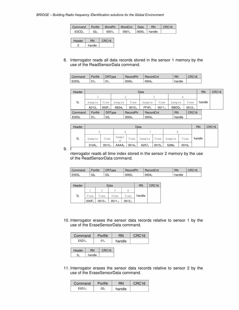
BRIDGE – Building Radio frequency IDentification solutions for the Global Environment
8. Interrogator reads all data records stored in the sensor 1 memory by the use of the ReadSensorData command.
Command PortNr DRType RecordPtr RecordCnt RN CRC16
E0D0h 01h 01h 0000h 0004h handle
Command PortNr DRType RecordPtr RecordCnt RN CRC16
E0D0h 01h 03h 0004h 0004h handle
9. Interrogator reads all time index stored in the sensor 2 memory by the use of the ReadSensorData command.
Command PortNr DRType RecordPtr RecordCnt RN CRC16
E0D0h 02h 03h 0000h 0004h handle
10. Interrogator erases the sensor data records relative to sensor 1 by the use of the EraseSensorData command.
11. Interrogator erases the sensor data records relative to sensor 2 by the use of the EraseSensorData command.
Command PortNr WordPtr WordCnt Data RN CRC16
E0CDh 02h 0001h 0001h 0000h handle
Header RN CRC16
0 handle
Header Data RN CRC16
02
1 2 3 4
handle
Sample Time Sample Time Sample Time Sample Time
A213h 000Fh AB34h 0010 h FF4Fh 0011 h BBDDh 0012 h
Header Data RN CRC16
02
5 6 7 8
handle
Sample Time Sampl
e Time Sample Time Sample Time
312Ah 0013 h AAAAh 0014h A257h 0015h 5286h 0016h
Header Data RN CRC16
02
1 2 3 4
handle
Time Time Time Time
000Fh 0010 h 0011 h 0012 h
Command PortNr RN CRC16
E0D1h 01h handle
Header RN CRC16
02 handle
Command PortNr RN CRC16
E0D1h 02h handle
BRIDGE – Building Radio frequency IDentification solutions for the Global Environment
Header RN CRC16
02 handle