Specification Manual... · 1 General foreword: Application of Akatherm PE pressure fittings General...
280
1 General foreword: Application of Akatherm PE pressure fittings General foreword General foreword: Application of Akatherm PE pressure fittings Akatherm PE pressure fittings have been used for more than 40 years in areas of application where the pipe system has to meet high standards of durability and reliability. These standards are met by combining the excellent material properties of PE with homogeneous welded joints. Water treatment installations Their high impact resistance, wide temperature range and outstanding chemical resistance make PE pressure pipe systems extremely suitable for the transport of waste water in water treatment installations. As well as standard fittings for this application, special fabricated fittings, dismantling joints and wall ducts are available. Waste water transport Good flexibility, high impact resistance and wide temperature range make PE pressure pipe systems extremely suitable for the use in pressure sewage systems such as public sewers, culverts etc. As well as standard fittings for this area of application, long radius bends made from pipe, special electrofusion couplers and customer made inspection chambers and pump pits are available. Swimming pool constructions The already mentioned properties high impact resistance, wide tempera- ture range and excellent chemical resistance make PE pressure pipe sys- tems extremely suitable for application in high quality swimming pool installations. As well as standard fittings for this application, special fabri- cated fittings, dismantling joints and wall ducts are available. Industrial process pipe systems The outstanding chemical resistance and wide temperature range make PE pressure pipe systems extremely suitable for installations in e.g. the process and food process industry. As well as standard fittings for this area of application, screw couplings and union ends for connection to valves and pumps are available. Transport of solids The high wear resistance, good flexibility and the smooth internal wall make PE pressure systems extremely suitable for the transportation of solids in amongst others sand & gravel dredging and mining industry. As well as standard fittings for this area of application, long radius bends made from pipe, flanged joints and electrofusion sockets are available.
Transcript of Specification Manual... · 1 General foreword: Application of Akatherm PE pressure fittings General...

1
General foreword: Application of Akatherm PE pressure fittings
General foreword
General foreword:Application of Akatherm PE pressure fittingsAkatherm PE pressure fittings have been used for more than 40 years inareas of application where the pipe system has to meet high standards ofdurability and reliability. These standards are met by combining theexcellent material properties of PE with homogeneous welded joints.
Water treatment installations Their high impact resistance, wide temperature range and outstandingchemical resistance make PE pressure pipe systems extremely suitable forthe transport of waste water in water treatment installations. As well asstandard fittings for this application, special fabricated fittings, dismantlingjoints and wall ducts are available.
Waste water transportGood flexibility, high impact resistance and wide temperature rangemake PE pressure pipe systems extremely suitable for the use in pressuresewage systems such as public sewers, culverts etc. As well as standardfittings for this area of application, long radius bends made from pipe,special electrofusion couplers and customer made inspection chambersand pump pits are available.
Swimming pool constructionsThe already mentioned properties high impact resistance, wide tempera-ture range and excellent chemical resistance make PE pressure pipe sys-tems extremely suitable for application in high quality swimming poolinstallations. As well as standard fittings for this application, special fabri-cated fittings, dismantling joints and wall ducts are available.
Industrial process pipe systemsThe outstanding chemical resistance and wide temperature range makePE pressure pipe systems extremely suitable for installations in e.g. theprocess and food process industry. As well as standard fittings for thisarea of application, screw couplings and union ends for connection tovalves and pumps are available.
Transport of solids The high wear resistance, good flexibility and the smooth internal wallmake PE pressure systems extremely suitable for the transportation ofsolids in amongst others sand & gravel dredging and mining industry. Aswell as standard fittings for this area of application, long radius bendsmade from pipe, flanged joints and electrofusion sockets are available.

General foreword: Application of Akatherm PE pressure fittings
2 General foreword

3
Table of contentsAbriged table of contents
Table of contents
1 "Plastic" material.............................................................................................................112 Material properties of PE..................................................................................................193 Planning criteria...............................................................................................................314 Standards ........................................................................................................................335 Installation.......................................................................................................................376 Planning and construction guidelines and stress types......................................................417 Basic calculations .............................................................................................................518 Jointing ...........................................................................................................................65
Short fittings for butt-welding ............................................................................................71Long fittings for butt-welding and electrofusion ...............................................................105Fittings made from pipe....................................................................................................123Backing rings and gaskets.................................................................................................177GOEMA pipe clips.............................................................................................................193
9 Welding polyolefins .......................................................................................................19910 Quality ........................................................................................................................211
Appendix A to E ...............................................................................................................215
Specification Manual PE pressure fittings
Price list 2011
Jointing techniques
Appendices

Total table of contents
4
Table of contents
Table of contents
General forewordGeneral foreword: Application of Akatherm PE pressure fittings .......................................... 1
Table of contentsAbriged table of contents .................................................................................................... 3Total table of contents......................................................................................................... 4
ForewordForeword Specification Manual.......................................................................................... 10
1 "Plastic" material1.1 Classification of plastics ............................................................................................... 111.2 Thermosets and elastomers.......................................................................................... 111.3 Thermoplastics............................................................................................................. 111.4 Characteristics of amorphous and semi-crystalline thermoplastics ................................ 121.5 Plastic processing machines ......................................................................................... 121.6 Mechanical properties.................................................................................................. 131.7 Thermal properties....................................................................................................... 151.8 Chemical properties..................................................................................................... 161.9 Processing characteristic: Melt index ............................................................................ 161.10 Physics of plastics....................................................................................................... 161.11 Chapter summary ...................................................................................................... 18
2 Material properties of PE2.1 General material properties of polyethylene (PE) .......................................................... 192.2 Properties of PE100 ..................................................................................................... 192.3 Chemical resistance ..................................................................................................... 212.4 Health assessment of PE .............................................................................................. 302.5 Chapter summary ........................................................................................................ 30
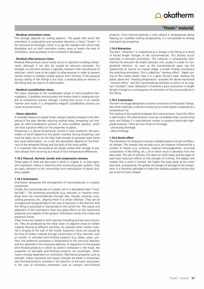
3 Planning criteria3.1 Selection criteria for PE pipe systems............................................................................ 313.2 User instructions .......................................................................................................... 313.3 Checklist for pipe and equipment contractors .............................................................. 32
4 Standards4.1 General ....................................................................................................................... 334.2 Minimum required strength (MRS) ............................................................................... 334.3 Pipe series number (ISO-S) ........................................................................................... 334.4 Maximum operating pressure (MOP)............................................................................ 344.5 Standard dimension ratio (SDR).................................................................................... 344.6 The polyethylene (PE) mark .......................................................................................... 344.7 Load capacity of welded PE100 pipe and fittings.......................................................... 354.8 Wall thicknesses and acceptable internal pressure load capacity for PE100 pipes.......... 354.9 Chapter summary ........................................................................................................ 36
Specification Manual PE pressure fittings

5
Table of contentsTotal table of contents
Table of contents
5 Installation5.1 Pre-requisites ................................................................................................................375.2 General ........................................................................................................................375.3 Classification criteria .....................................................................................................375.4 Influence of operating conditions..................................................................................375.5 Structural analysis .........................................................................................................37
6 Planning and construction guidelines and stress types6.1 Internal and external pressure loads ..............................................................................416.2 Stress due to pipe deflection.........................................................................................416.4 Loads on buried pipe systems .......................................................................................426.5 Causes of length change ..............................................................................................446.6 Compensation for length changes ................................................................................446.7 Brackets .......................................................................................................................456.8 Construction and installation of buried pipe systems.....................................................466.9 Principles of constructing and installing concrete-encased pipe systems ........................486.10 Chapter summary .......................................................................................................49
7 Basic calculations7.1 Factors influencing pipe system design..........................................................................517.2 Calculating pipe parameters .........................................................................................51
8 Jointing8.1 General ........................................................................................................................658.2 Detachable connections................................................................................................658.3 Non-detachable connections.........................................................................................678.4 Chapter summary .........................................................................................................68
ForewordForeword price list ..............................................................................................................70
Short fittings for butt-weldingStub flanges .......................................................................................................................71Tees ...................................................................................................................................77Bends .................................................................................................................................84Reducers ............................................................................................................................86End caps.............................................................................................................................95Unions................................................................................................................................97Adaptors ..........................................................................................................................103
PE100 pressure fittings
Price list 2011

Total table of contents
6
Table of contents
Table of contents
Long fittings for butt-welding and electrofusionStub flanges .................................................................................................................... 105Tees................................................................................................................................. 107Elbows............................................................................................................................. 111Bends .............................................................................................................................. 114Reducers.......................................................................................................................... 115End caps.......................................................................................................................... 118Electrofusion couplers FRIALEN ........................................................................................ 120
Fittings made from pipeTees welded .................................................................................................................... 123Tees welded with reduced branch.................................................................................... 128Tees extrusion welded with reduced branch..................................................................... 134Tees reduced machined - pressure class ........................................................................... 142Bends seamless formed.................................................................................................... 150Bends welded .................................................................................................................. 175
Backing rings and gasketsProfile backing rings PP with ductile iron core .................................................................. 177Backing rings PP with ductile iron core............................................................................. 179Profile backing rings ductile iron and coated .................................................................... 181Backing rings GRP............................................................................................................ 183Flange connections .......................................................................................................... 185Blind flanges.................................................................................................................... 187Gaskets ........................................................................................................................... 189Profile gaskets ................................................................................................................. 191
GOEMA pipe clipsPipe clips complete .......................................................................................................... 193Pipe clips components ..................................................................................................... 195
9 Welding polyolefins9.1 General ..................................................................................................................... 1999.2 Welding procedures................................................................................................... 1999.3 Test procedures for evaluating welds ......................................................................... 2069.4 Chapter summary ...................................................................................................... 209
10 Quality10.1 Production quality.................................................................................................... 21110.2 Quality inspection during work-site assembly ........................................................... 21110.3 Leak test prior to initial use ...................................................................................... 21110.4 Chapter summary .................................................................................................... 212
GOEMA pipe clips
Jointing techniques

7
Table of contentsTotal table of contents
Table of contents
Appendix AGeneral Diagrams.............................................................................................................215
Appendix BDiagrams: Pressure pipe systems .......................................................................................233
Appendix CExplanation of the applied formulas and abbreviations......................................................245
Appendix DConversion tables .............................................................................................................249
Appendix EStandards and guidelines ..................................................................................................251
IndexAlphabetical index ............................................................................................................255Index of article numbers ...................................................................................................259
General conditionsGeneral conditions............................................................................................................277
Appendices

Total table of contents
8
Table of contents
Table of contents

9
Specification ManualPE pressure fittings

Foreword
10 Foreword
Foreword Specification ManualThe economic and technical advantages of plastic as opposed to con-ventional materials (such as steel) have caused builders and projectdevelopers to become strongly interested in the applications of suchmaterials. For this reason, thermoplastics are an increasingly morefrequent component of many community and industrial facilities. Highdemands on quality and comparatively low costs are therefore factorsthat cause planners and fabricators to use plastics in projects with everincreasing frequency. Nowadays, plastic has become an indispensablesubstance employed in all areas of modern life. Associated with theterm "plastic" is a variety of synthetic polymers that, due to their diffe-rent qualities, are used in many sectors, such as engineering, medicine,clothing industry and the building trades. This list of industries is onlymeant to have an exemplary character and does not represent any indi-cation of value, as the industrial areas in which plastic is an essentialmaterial could be lengthened in any number of ways. However, whenmention is made of plastic in this Specification Manual, it is primarilythe PE100 (polyethylene) polymer employed by Akatherm BV that ismeant.
This Specification Manual is a useful tool providing extensive informationfor both the engineer and contractor.Extensive planning and fabrication requires users to be sufficiently fami-liar with material-specific qualities, have this information clearly andcomprehensively presented to them and have a variety of possibilitiesindicated. Based on the more than 40-year experience of Akatherm BVwith PE and PP pipe systems, Akatherm is able to present with pride anup-to-date Specification Manual for PE100. This is a revised version ofthe Akatherm Technical Manual for PE/PP Pipe Systems compiled underthe technical and editorial supervision of Dipl.-Ing. (FH) Jürgen Thielen(Akatherm FIP GmbH) in collaboration with PM Engineering in Leimen, afirm involved in polymer engineering and the design of industrial facili-ties. The process has yielded a manual in which tables, diagrams, varia-bles, guidelines and installation tips are partly reprinted and partly arereformulated, always in compliance with all the NEN, EN, ISO and othernational and international standards that were important and valid at thetime of printing in March 2011, while also taking other guidelines andregulations applicable to pipe construction into account.
The result is a Specification Manual that provides the engineer and con-tractor with the appropriate calculation and dimensioning principles, aswell as installation instructions applicable from the beginning of theplanning stage to the completion of a pipe system.
This Specification Manual is to be viewed as a contribution to customerservice in association with the wish to standardise the use of plasticmaterials and to make their applications generally understandable. Forcases involving special applications, as experienced Akatherm BVemployee will always be placed at your disposal. The data contained invarious chapters corresponds to the current state of our knowledge andis essentially based on standards involving plastics or pipe construction.Nevertheless, the content of the Specification Manual is only of an infor-mative nature, and its use does not entail any legal obligation.
There are no claims concerning certain product qualities or their appro-priateness for a specific requirement connected with the data in theSpecification Manual. All liability for deviations from existing standards,deficiencies or errors, as well as infringement of third party industrialrights is excluded. The responsibility of and warranties offered by usersfor proper planning and construction of thermoplastic components andfacilities are not limited by the use of this manual. For its part, AkathermBV guarantees the faultless quality of its own products in accordancewith its terms of delivery and sale. Reproduction and copying even ofextracts of this Specification Manual can only occur with the written con-sent of Akatherm BV.

11
"Plastic" material
"Plastic" material
1 "Plastic" materialPlastic is a familiar term and a frequently-used material both in enginee-ring and in daily life. Since this material is employed in almost all areas ofour everyday lives, it has become indispensable. Although we use it on adaily basis, most people are forced to admit that they actually know littleabout the substance itself.Planners and manufacturers in the fields of pipe construction, mechanicalengineering and the manufacture of special parts are also increasinglyconfronted with plastic materials. It is at this point that questions of thefollowing type arise:What is plastic? How do I handle the material? What advantages doesthe material have over conventional materials such as concrete, ductileiron, etc.?To lighten the introduction to plastics we have compiled the most impor-tant information about plastics and polymer processing machinery. As aresult, this chapter is purely informative.
1.1 Classification of plastics
Plastics are subdivided into three large groups. Figure 1.1 provides anoverview of the polymer groups and figure 1.2 presents their structuralmodels.
Figure 1.1 Classification of plastics into main categories: thermoplastics, thermosets and elastomers
1.2 Thermosets and elastomers
Thermosets and elastomers play a rather secondary role in plastic pipeconstruction and are therefore only discussed briefly in this SpecificationManual.
Thermosetting plastics have a close-meshed macromolecular structure(figure 1.2). As a consequence, these plastics are usually hard, brittle andno longer meltable. For this reason manufacturers mix the molten masswith fillers that not only have a "filler" (i.e. material saving) function butare primarily added to improve material properties.Areas of application relating to pipe construction are plant engineering(fibre-glass reinforced containers, flanges, etc.).Elastomers (better known as "vulcanised rubber") are made from naturalor synthetic rubber by means of an interlinking reaction (vulcanisation).The vulcanisation of rubber creates a broad-meshed, loose interweaving,which gives the material its typical rubbery qualities under the normalconditions of its use. Elastomers are used in pipe construction as seals(O-rings, flat gaskets, etc.) between connected elements.
1.3 Thermoplastics
Thermoplastics are by far and away the most important for pipe con-struction. The plastic often used in pipe fabrication is polyolefin, of whichthe most important representatives are polyethylene and polypropylene.They belong to the category of semi-crystalline thermoplastics. As a rule,thermoplastics are produced by one of the three following processes:- Polymerisation- Polyaddition- Polycondensation The different processes produce various plastics with various properties.Within each individual manufacturing process, there are special procedu-res that influence the appearance and characteristics of the specific plas-tics. Thermoplastics can be further subdivided into two groups: adistinction is made between amorphous and semi-crystalline thermoplas-tics. It should be further mentioned that plastics are seldom used in theirpure form but usually as mixtures in what are known as blends or com-pounds. The composition of which depends on their purpose and area ofapplication. Blends allow new or altered characteristics (mechanical, phy-sical or chemical properties) to be produced.It is however not possible to combine just any type of plastic with anyother type. Very often, bonding agents or other additives are needed tocreate any bond at all.
Plastics
Thermoplastics Thermosets Elastomers
Amorphous Semi-crystalline
1. 2.
3. 4.
1 Thermosets2 Elastomers3 Semi-crystalline
thermoplastics4 Amorphous thermoplastics
Figure 1.2 Structural model of thermosets, elastomers and semi-crystalline and amorphous thermoplastics
"Plastic" material
12 "Plastic" material
1.3.1 Amorphous thermoplasticsThe arrangement of the molecular bond depends on several factors.Especially important is the chemical structure of the chain molecule (orthe macro-molecular structure). An ordered spatial structure is impededby long and cumbersome lateral chains. Since the molecular bond occursamidst what amounts to perfect disorder, the structure resembles thestructure that of a cotton wad. The best known representatives of thegroup are:- polystyrene (PS)- polycarbonate (PC)- polymethyl methacrylate (PMMA -> plexiglas)- polyvinyl chloride (PVC)
In uncoloured state, amorphous thermoplastics are as clear as glass.
1.3.2 Semi-crystalline thermoplasticsSemi-crystalline thermoplastics develop both chemically-uniform as well asgeometrically-structured regions (figure 1.2), which means that there areregions in which crystals form. Crystals are understood to be parallel grou-pings of molecular segments or folds in molecular chains. Some chainmolecules can therefore partly traverse the crystalline and amorphous regi-ons, or they can even belong to several crystallites at the same time. Semi-crystalline thermoplastics are white in colour. Due to the dense arrange-ment of molecules in crystalline bonds, crystallites refract light.The degree of crystallisation greatly influences the properties and trans-parency of plastic in its uncoloured state. The use of an accelerated coo-ling rate significantly affects the crystallisation tendency of the material.Important types of semi-crystalline thermoplastic are:- polyethylene (PE)- polypropylene (PP)- polyoxymethylene (POM)
1.4 Characteristics of amorphous and semi-crystallinethermoplastics
A comparison of amorphous and semi-crystalline thermoplastics reveals afew distinctive properties. The most important qualitative distinctions arecontrasted below.In contrast to semi-crystalline thermoplastics, amorphous thermoplasticsdisplay:- greater strength- greater rigidity- greater surface hardness- better surface quality- less thermal expansion- less distortion
In contrast to amorphous thermoplastics, semi-crystalline thermoplasticsdisplay:- greater resilience- less impact sensitivity- greater flexibility and elasticity
1.5 Plastic processing machines
Plastic processing machines are used to transform raw plastic (mostly ingranular form) into semi-finished products. The following section brieflysketches the most important plastic processing machines and explainstheir functions and applications in simple terms. Emphasis will be placedon machines that are important for the manufacture of plastic pipes andfittings.
1.5.1 ExtruderExtruders are used to manufacture pipes, along with associated dies,cooling units, extractor units and cutters. Due to increased qualitystandards, a modern extrusion installation now includes connected inlinemeasuring systems (e.g. wall thickness metres) that enable immediateresponses to irregularities during the production process. The functionalprinciple of the extruder involves melting (i.e. plasticising) raw material(e.g. granulate) and shaping it into a new form by pressing it through adie linked to a cooling unit.
An extruder (figure 1.4) can be equipped with one, two or several screws(also known as worm shafts). Depending on the material being pro-cessed and the semi-finished product being manufacture, special extru-ders are individually made to suit the needs of the production process.Especially important for the actual plasticising processes (i.e. the meltingof the supplied raw material) are the screws, the screw geometry and thetemperature of the heated cylinders. Due to the shear force in the mate-rial, it is plasticised at the corresponding cylinder temperature and pres-sure build-up by the extruder screw geometry and the die, and thentransported further along the screw channels. Material to be plasticised(melted) is fed into the extruder, usually in granular form. Often, three-section screws are used in standardised single-screw extruders, alongwith barrier screws. The plasticised material is pressed through the dieand cooled in a sizing and cooling section. The fitting (e.g. pipe, profile,solid bar) is fixed in the sizing unit. As a result of this process, the plastic,specifically the macromolecule chains, are forced into an arrangementand alignment. In technical terminology, this is called "orientation".Extrusion involves a continuous process (i.e. the process is uninterruptedunless the machine is switched off or not supplied with new material).
1 Extruder2 Die head3 Sizer4 Water bath
5 Caterpillar6 Cutting saw7 Tip unit
Figure 1.3 Principle layout of a pipe extrusion installation

13
"Plastic" material
"Plastic" material
Figure 1.4 Layout of an extruder
1.5.2 Injection moulding machineThe layout of an injection moulding machine (figure 1.5) resembles theextruder in its structure. The most important distinction between the twomachines involves the motion of the screw. In addition to the rotary motionalready described for the extruder, it also makes an axial movement.In contrast to extruders, the injection moulding machine is involved in a dis-continuous process. A discontinuous production process makes specialdemands on the machine, the mould and the associated and necessarymould cooling. There are three important parameters for the manufactureof an injection moulded part.- temperature- time- pressure
These three parameters have an extremely important impact on the injec-tion moulding process, which is organised into three functional steps:- plasticisation- injection- cooling
The plastic to be processed is plasticised while moving along the screwthrough the heated cylinder. The actual plasticising process correspondsessentially to extrusion. The plasticising material is moved forward by thescrew in the direction of the screw tip.
The plasticising material is simultaneously pre-compressed. Once there issufficient material in the "accumulator", which is at the end of the plas-ticising unit, the material is squeezed through an injector into the mould.To prevent material shrinkage, plasticised material is compressed for acertain time during the cooling phase. The machine parameters dependon the material being worked and the fitting being manufactured. At theend of the injection cycle, the process begins again.
1.6 Mechanical properties
1.6.1 Assessing creep behaviourCreep behaviour is among the most important tested factors for pipesand fittings. It indicates the life expectancy possessed by the plastic pipeor fitting when it is subject to internal pressure. The internal pressureinvolved generates stress in the pipe wall. An appropriate reference stress(�r) is based on the relationship of internal pressure (�i), the safety coeffi-cient (SF) and the diameter - wall thickness ratio (SDR). The referencestress (�r) can be calculated using the well-known boiler formula. Itreads:
Equation 1.1
�ref = Reference stress (N/mm2)�acc = Acceptable stress (N/mm2)�i = Internal pressure (bar)SDR = Standard dimension ratioSF = Safety factor = General design coefficient "C"
The reference stress (�r) conforms, in practice, to the stress on thecircumference of the internal pipe surfaces. In contrast to this stress, thestress in the axial direction of the pipe is only half as large. In applying theboiler formula, the acceptable stress (�acc) of the corresponding materialprovides the basis for dimensioning the plastic pipe. Additionallyextremely important is the fact that the stress at break has a very largedependence on the thermal load and period of load. Usually, tests are
1 Screw2 Cylinder3 Hopper
4 Motor5 Drive6 Heater
Figure 1.5 Functional principle of a injection moulding machine
a) The turning screw takes extracted granulate from the bulk hopper and feeds it along the screw channel to the screw tip.
b) The mould is closed, the injection unit moves against the feedbush, the screw operates as a piston to press plasticisedmoulding material into the mould.
c) The cooled injected material drops out of the opened mould,the screw moves new moulding material to the screw tip, theinjection unit withdraws from the tip.
1 Movable mould part2 Injection-formed component3 Mould cavity4 Fixed part of the mould5 Nozzle6 Heating band7 Material cylinder8 Screw9 Bulk material hopper

"Plastic" material
14 "Plastic" material
conducted on water-filled sections of standardised pipe. During the tests,the test sample is placed in a water bath.
Special applications require the testing of pipe sections filled with theintended flow medium. The results of such tests are shown on a double-logarithm diagram in which the reference stress is plotted over time. Thetests are conducted at various temperatures. The bend in the curve indi-cates when pipe failure is to be expected. Results of the tests at highertemperatures allows an interpolation of the creep behaviour for a pipe atlower temperatures. This provides an indication of the life expectancy ofa pipe under certain conditions. Time curves for PE100 are displayed inappendix A1.
1.6.2 Assessing the mechanical variablesThe tensile test is described in NEN-EN-ISO 527-1, NEN-EN-ISO 527-2 andNEN-EN-ISO 527-3.In the tensile test, precisely defined samples are stretched to the breakingpoint and the required force measured. This usually involves a 1-axialload on the sample. The force used for this purpose is applied in a time-dependent manner. An adjustment screw on the tensile testing machineis used to plot the relationship between force and length change in thetest, enabling a force-linear expansion diagram to be made, which canbe converted into a stress-elongation diagram.
Figure 1.6 Force-linear expansion diagram (tensile force)
The diagram provides information on the following characteristic varia-bles:- Elongation (�) - linear expansion (�l) as a percentage of the initial
length (l0) at each time interval in the test.- Tensile strength (�B) - which is the tensile stress at maximum load.- Breaking strength (�B) - which is the tensile stress at the moment of
breakage.- Yield stress (�Y) - which is the stress at which the increase in the
stress-elongation curve is first equal to null.
The mechanical variables are very strongly dependent on the test conditi-ons. The tests are therefore conducted under normal climate conditions(23°C and 50% relative humidity). The tensile test is one of the short-term tests and the knowledge gained does not indicate anything aboutthe behaviour of material under a long-term mechanical load. Semi-crystalline materials such as PP and PE mostly display a distinct yield stressand a high degree of elongation (figure 1.6).
1.6.3 Assessing the elasticity modulus (creep modulus)
Short-term valuesThe elasticity modulus (E-modulus) is the ratio of stress (�) to elongation (�):
Equation 1.2
�1 = Normal stress at 0.05% elongation (N/mm2)�2 = Normal stress at 0.25% elongation (N/mm2)�1 = Elongation of 0.05 (%)�2 = Elongation of 0.25 (%)F = Force (N)A0 = Starting section (mm2)�l = Change of length due to force (F) (mm)l0 = Starting length (mm)E = E-modulus (N/mm2)
DIN 53457 describes the determination of the E-modulus from the ten-sile test (Et), the compressive test (Ed), from the 3-point flexural test (EF3)and the 4-point flexural test (EF4).
Long-term valuesThe E-modulus under tensile load is determined by means of the creeptensile test specified in NEN-EN-ISO 899-1. The creep tensile test allowscalculation of the creep modulus (EcR). In general, the tensile test is givenpreference over the flexural or compressive tests, as its performance isusually easier. The test items are non-axially stressed in a controlled testenvironment by a force that remains constant throughout the testperiod. If these tests are conducted at temperatures resembling the sub-sequent application temperature range, the diagram provides the engi-neer with important data to assess the behaviour of the correspondingmaterial.
1.6.4 Impact resistanceThe procedures for the impact flexural and notched impact flexural testsare described in DIN 53453 and DIN 53753. The tests are used to deter-mine impact behaviour, otherwise known as the resilience of the plastic.The variable measured is the quantity of absorbed impact energy in rela-tion to the cross-sectional areas that results in breakage of the bar orplate-shaped test specimen, which may be notched. Force is generatedby a pendulum impact tester, which strikes the specimen at high speed.In Europe, two test procedures (notched and unnotched) are most com-monly performed: one known as "Charpy" uses a pendulum impact tes-ter as specified in NEN-EN-ISO 179 and the other, which is called "Izod",uses a Dynstat apparatus as specified in NEN-EN-ISO 180. Three definednotch types are used to determine notched impact resistance.
1.6.5 Surface hardnessSurface hardness indicates the resistance that a defined specimen dis-plays in order to prevent it from being penetrated. The Shore test, speci-fied in NEN-EN-ISO 868, may make use of two procedures to determineShore hardness: these are known as Shore A and Shore D. The two pro-cedures differ in the geometry of the test specimen used (test needle).Figure 1.7 shows the two different test objects. Shore hardness is dimen-sionless, and the range of hardness varies between values of 0 and 100.The Shore A procedure is predominantly applied to soft plastics, whileShore D is used with hard ones.In addition to the Shore hardness test, the hardness of a material can bedetermined as specified in NEN-EN-ISO 2039-1 in terms of its ball inden-tation hardness. This method is mostly used when the hardness of amaterial can no longer be established by the Shore procedure. A ball witha 5 mm diameter serves as the test object, which is subject to a definedload for 30 seconds.
Curve 1: hard brittle plastic without yield range, e.g. polystyrene (PS)Curve 2: ough hard plastic, e.g. polyethylene (PE)Curve 3: flexible elastic plastic, e.g. plasticised polyvynil chloride
(PVC-P)
Tens
ile f
orce
F in
N
Linear expansion �l in mm

15
"Plastic" material
"Plastic" material
Figure 1.7 Test objects for Shore A and Shore D hardness tests
1.7 Thermal properties
1.7.1 Heat expansion coefficientIn determining the heat expansion coefficient, a distinction is madebetween the linear expansion coefficient (thermal length expansion coef-ficient (a�)) and the cubic expansion coefficient (spatial expansion coeffi-cient (��)). The linear expansion coefficient (��) indicates the amountthat a material with a standard length of one metre will lengthen or shor-ten under a temperature change of 1 K. The spatial expansion coefficient(��) indicates the amount that a cubic meter of material will lengthen orshorten under a temperature change of 1 K. DIN 53752 describes thetests for the linear and cubic expansion coefficients. The unit of theexpansion coefficient is (1/K), (K-1) or (mm/mK).
1.7.2 Deformation resistance to heatAll property changes are important to the engineer and especially behavi-ours in response to heat effects. For this reason, various tests are conduc-ted to ascertain the approximate boundary temperatures below whichdeformation does not occur. NEN-EN-ISO 75-1 and NEN-EN-ISO 75-2describe methods of determining heat resistance.
Three procedures are used to determine deformation resistance:1. Martens (DIN 53462)2. Vicat3. ISO/R 75 (ASTM D 640)
The determined variables do not, however, permit any conclusions to bedrawn about the working temperature of the tested plastics. Valuesascertained for plastics are only comparable when they are tested underidentical conditions and procedures. The outside temperature effects ofair or fluid as well as the form and manufacturing method of the sampleshave a large influence on the measured results.
1.7.3 Heat conductivityThe heat conductivity or the heat coefficient (), measured as (W/mK), isa temperature dependent material characteristic that indicates some-thing about the capacity of a material to conduct heat. An indication ofheat conductivity or insulation capacity (negative thermal conductivity) ofa material can be provided by tests specified in DIN 52612-1 or DIN52613 (ISO/DIS 8497-1988). The heat conductivity of a substance can besignificantly influenced by the filling, reinforcements, auxiliary materials,and colouring.
1.7.4 Heat transfer coefficientThe Heat transfer coefficient (�) is an important factor needed to calcu-late the heat transition coefficient () as well as specific heat conductivity(l) of a material. The heat conductivity, like the heat transfer coefficient, isstrongly dependent on other influences, such as separation plane, geo-metry and flow rate of the medium.
1.7.5 Heat transition coefficient The heat transition coefficient (k) provides information about the insula-tion capacity of a material. The unit is (W/m2K). The smaller the k-valueis, the higher the insulation capacity of the material. The heat transitioncoefficient is computed with the equation:
Equation 1.3
k = Heat transition coefficient ( - )�w1 = Heat transition coefficient of medium 1 to the wall (W/m2K)�w2 = Heat transition coefficient of the wall to medium 2 (W/m2K) = Heat conductivity of the wall (W/mK)dw = Thickness of the separation wall (m)
1.7.6 Burning behaviourPlastics are organic compounds that are, by their nature, combustible.The European standard NEN-EN 13501-1 defines a classification systemfor material burning behaviour for building products and building struc-tures. The burning behaviour of finished products (in the manner thatthey are used) must be described in terms of the extent to which thematerial contribute to the development and spread of fire and smoke inan area or environment. In the case of fire, building products are exposedto a fire ignited in a given area. This fire can then grow (increase) and
Shore A test needle Shore D test needle
Stage 1: Combustibility
Table 1.1
Class Fire tests Spreading of flames Contribution Practice
F Not tested or does not meet class E Unclassified Undefined Extremely combustibleE EN-ISO 11925-2 (15 sec-Fs<150 mm-20 sec) Spreading of flames 100 kW <2 min. Very high contribution Very combustibleD EN 13823, Figra <750 W/sEN-ISO 11925-2 (30 sec-
Fs<150 mm-60 sec)Spreading of flames 100 kW >2 min. High contribution Quite combustible
C EN 13823, Figra <120 W/s + Thr <15 MJEN-ISO11925-2 (30 sec-Fs<150 mm-60 sec)
Spreading of flames 100 kW >10 min. Large contribution Combustible
B EN 13823, Figra <120 W/s + Thr <7.5 MJEN-ISO 11925-2 (30 sec-Fs<150 mm-60 sec)
No spreading of flames Very limited contribution Very difficult tocombust
A2 EN ISO 1182 of EN-ISO 1716 plusEN 13823,Figra <120 W/s+ Thr <7,5 MJ
No spreading of flames Hardly any contribution Practicallyincombustible
A1 EN ISO 1182 = IncombustibleEN-ISO 1716 = Caloric values
No spreading of flames No contribution Incombustible

"Plastic" material
16 "Plastic" material
finally spread. The scenario contains three components of fires that cor-respond the stages in the development of a fire:- Combustibility: the starting of a fire by ignition using a small flame on
a small surface/product.- Smoke production: development and potential spread of fire.- Burning drops/fragments: outbreak of fire when all combustible
material contribute to the fire potential.
Combustion classification
Stage 2: Smoke production
Stage 3: Burning drops/ fragments
Fire safetyThe required fire safety level of a building is not the same in all Europeanmember states. Every member state may make its own regulations todetermine the products that may be used and the combustion class thatis suitable for the circumstances.
Level of fire safety in the NetherlandsThe fire-safety level in the Netherlands is specified in the NetherlandsBuildings Decree (Bouwbesluit), which only applies to aboveground pipesystems. Burning behaviour can be disregarded for underground pipesystems.
1.8 Chemical properties
1.8.1 Chemical resistanceThe chemical resistance of PE to contacting media will be treated in detailin Chapter 2 (table 2.3).
1.8.2 PermeationPermeation is regarded as the diffusion of a medium through a plastic(e.g. container wall, shaft wall or pipe wall). Contact between plastic andchemical medium can, under certain circumstances, result in moistureexpansion or dissolution. Problems can also result from the dislodging ofmaterial by softening and processing agents, as well as from the bleedingof colouring. Practical testing procedures are presented in DIN 53405(dislodging) and NEN-EN-ISO 183 (bleeding of colouring).
1.8.3 Water absorptionMany plastics tend to absorb water. Due to swelling the dimensional sta-bility changes. PE is water-repellent, which means that it cannot bedamaged by swelling. The test procedure is described in NEN-EN-ISO 62.
1.9 Processing characteristic: Melt index
Determination of the melt-mass flow rate (MFR) as specified in NEN-EN-ISO 1133, also known as the melt flow index (MFI), is a standardised tes-ting method for obtaining a relatively quick and quantitative indication ofa plastic's flow behaviour. The MFR value indicates the amount of ther-moplastic molten mass pressed through a standardized nozzle during 10minutes of steady piston force and constant melt temperature. Table 1.4indicates the test conditions:
The melt volume flow rate (MVR), also known as the melt volume index(MVI) is used to test the flow behaviour of a molten mass at constant pis-ton force and defined temperature. The unit of the MRV is cm3/10 min.
1.10 Physics of plastics
1.10.1 Residual stressAll plastic components possess a certain residual stress potential, which isnot attributable to external forces but exists on account of manufactu-ring and cooling conditions. In the process of extruding plates, pipes andprofiles, molten mass is pressed through a die, causing the macromole-cule to be stretched. Subsequently, it is cooled and fixed in a sizing unit.Since the pipe is cooled from the outside in, the pipe wall cools at sub-stantially different rates.This cooling behaviour has consequently effects on the structure and/orthickness of the pipe shell.In the pipe wall results at the initially cooled side residual compressive stress(�D) and at the subsequently cooled side residual tensile stress (�T) (figure1.8). These stresses may be significantly reduced by means of tempering(i.e. reheating the pipe to a defined temperature). The subsequent heatingreduces the existing residual stresses, which have substantial effects on thedimensional stability, retraction, shrinkage and service life of the pipe.Dimensional stability is extremely important for pipes and components,since a change in diameter can have negative consequences for the leaktightness of connections. Usually, PE pipes are tempered.
Figure 1.8 Stress in the pipe wall
The stresses normally equally offset each other. If external or internalinfluences cause the stresses to fall into disequilibrium, the componentcan be deformed.However, the cooling procedure is not the only cause of residual stressesin a plastic component. The following sections describe other types ofstress that have residual effects on a pipe or fitting.
Class Description
s3 Great deal of smoke productions2 Average smoke productions1 Little smoke production
Class Description
d2 Fragments burning longer than 10 sec.d1 Fragments burning shorter than 10 sec.d0 No production of burning fragments
Test specification Test conditions
ISO 1133 Temperature (°C) Load (kg)1 190 2.166 190 10.0012 230 2.1618 190 5.0020 230 5.00Table 1.2
Table 1.3
Table 1.4 Test specifications and conditions for determining the MFR value
1
2 4
3
1 Pipe wall exterior2 Pipe wall interior3 �D = compressive stress4 �T = tensile stress
17
"Plastic" material
"Plastic" material
- Residual orientation stressThis strongly depends on cooling patterns. The speed with which theorientation in longitudinal and transverse directions is fixed ("frozen" inthe technical terminology), which is to say the strength with which heatdissipation acts on both orientation states, raises or lowers the level oforientation, causing stresses to be increased or decreased.
- Residual after-pressure stressResidual after-pressure stress mostly occurs in injection-moulding compo-nents, although it can also be caused by extrusion processes. Forexample, an extrusion process is typically involved in the manufacture ofsolid bars, which have to be subject to after-pressure in order to preventcavities (holes) or bubbles (empty spaces) from forming. If the pressureduring cooling of the fittings is too high, a residual pressure remains inthe fitting that can lead to its deformation.
- Residual crystallisation stressThis stress originates in the crystallisation phase of semi-crystalline ther-moplastics. Crystallites forming when the molten mass is cooling are sub-ject to contraction (volume change). Cooling that occurs in an unevenmanner and results in a temporarily irregular crystallisation process cancause structural strains.
- Stress reductionA remedial measure to abate frozen stresses (residual stresses) is the tem-pering of the pipe. Besides reducing residual stress, tempering can insti-gate an after-crystallisation process (in semi-crystalline plastics), whichcan have a positive effect on the properties of plastic.Tempering is a special temperature control or heat treatment, the para-meters of which depend on the plastic involved. During tempering, caremust be taken not to set the heat high enough to generate reset forcesand cause deformation. As a rule, the parameters depend on the thick-ness of the tempered fittings and the level of the stress profile.It is important that the products are slowly cooled after storage to pre-vent stresses from recurring as a result of local temperature differences.
1.10.2 Flexural, thermal, tensile and compressive stresses These types of stress are discussed in detail in chapter 6, as they repre-sent important criteria in planning and constructing pipe systems. Theyare basic elements in the construction and manufacture of plastic buil-ding supplies.
1.10.3 OrientationOrientation designates the arrangement of macromolecules in a plasticcomponent.Initially, the macromolecules of a plastic are in a disordered state ("knot-ted ball"). The processing procedures (e.g. extrusion or injection moul-ding) force the macromolecules through dies, moulds, extractor units,cooling processes, etc., aligning them in a certain direction. They can bearranged both longitudinally (in the case of extrusion in the direction thatthe fitting is extracted) or transversely to the centre line. The nature andalignment of the orientations have very great effects on the mechanicalproperties and stability of the product. Orientation results from shear andexpansion forces.Shear forces are created in both injection moulding and extrusion proces-ses. They are produced by the shear strain of adjacent strata of moltenmaterial flowing at different velocities, for example when molten mate-rial is clinging to the wall of the mould. Expansion forces are caused bythe flow of molten material through constrictions or flow channels, suchas nozzles. In extruded semi-finished products (e.g. plates, pipes, pro-files), the preferred orientation is longitudinal to the extrusion directionand less optimally in the transverse direction. In opposition to the pressedsemi-finished products in which no distinct orientation is the result, theproperties of extruded semi-finished products are anisotropic, whichmeans strongly dependent on orientation. Mechanical properties such asstrength, impact resistance and impact strength are better in anisotropicsemi-finished products oriented in the direction of extrusion and poorerin the case of transverse orientation such as isotropic semi-finished
products. Since thermal elasticity is only utilised in temperatures abovefreezing (or crystallite melting temperature), it is not possible to remedyorientation by tempering.
1.10.4 RetractionThe term "retraction" is understood as a change in the fitting as a resultof forced length changes of the macromolecule. This process occursespecially in extrusion procedures. The molecule is consequently stret-ched by the extrusion die and/or extractor unit, usually in a axial (i.e. lon-gitudinal) direction. As soon as the macromolecule again has theopportunity to resume its original shape, a length change counteractsthe stretching orientation. This is called the "memory effect". Rapid coo-ling of the molten plastic fixes it in a given (frozen) state. Heating theplastic above the "freezing temperature" activates the above-mentioned"memory effect" and the macromolecule attempts to return to its origi-nal ("knotted") state. Retraction is therefore a pure contraction in length(length change) as a consequence of orientation of the macromolecule inthe fitting.
1.10.5 ContractionThe term shrinkage designates a volume contraction of the plastic fittings.Like other materials, a volume increase occurs when plastic is exposed to atemperature rise.The cooling of the material instigates the inverse process. Since this effectis well-known, this phenomenon must be considered when constructingtools and fittings if a manufacturer wishes to produce technically high-grade products. There are two kinds of shrinkage:- processing shrinkage - after-shrinkage
1.10.6 Notch effectThe calculation of component stresses is ideally based on tensile and flexu-ral stresses. The stresses that actually occur are however influenced by anumber of factors (e.g. scratches, material inhomogeneities, structuralcomposition of the fitting, etc.), all of which result in deviation from theideal state. The size of notches, the radius of notch bases and the types ofload have important effects on the strength of a fitting. The deeper andsharper that a notch is formed, the higher the stress peak at the notchbase and, consequently, the greater the danger of damage to the compo-nent. It is therefore advisable to make the smallest possible notches thatare round (circular) shaped.

"Plastic" material
18 "Plastic" material
1.11 Chapter summary
Plastic Plastic is divisible into three main groups: thermoplastics, thermosets and elastomers.
Elastomers Elastomers are better known as rubber. They are wide-meshed, spaciously interlinked synthetic or natural rubber compounds. Interlinking is enhanced by vulcanisation.
Thermosets Thermosets possess a close-meshed interlinked macromolecular structure. They are hard, brittle and no longer plasticisable (meltable).
Thermoplastics Thermoplastics can be divided into amorphous and semi-crystalline thermoplastics.Polyolefin This compound belongs to the group of semi-crystalline thermoplastics. Its most important representatives are
polyethylene (PE) and polypropylene (PP).Plastic processing machines Extruders, injection moulding machines and calendars (not discussed in this manual) are machines used to manu-
facture plastic semi-finished products.Extruder An extruder is responsible for plasticising raw materials. Used, for example, in the manufacture of pipes, profiles
and plates. Continuous process.Injection moulding machine Injection moulding involves a discontinuous manufacturing process. The screw performs both a rotational and an
axial motion. Important parameters for injection moulding are: temperature, time and pressure. Process steps are: plasticisation, injection and cooling.
Internal pressure creep test Simulates the life expectancy of a plastic pipe under an internal pressure load. The associated reference stress (�ref) is a function of the internal pressure, mean pipe diameter and wall thickness. It is calculated using the boiler formula.
Short-term tensile test The short-term tensile test involves stretching a sample bar to the breaking point. The result provides an indica-tion of the mechanical values of the tested material. The most important mechanical values are: expansion, ten-sile strength, breaking strength and breaking strain.
Elasticity modulus (Creep modulus) The elasticity modulus is the ratio of stress to expansion.Creep tensile test The creep tensile test is used to determine the creep modulus.Impact resistance Impact resistance is determined by means of the impact flexural test and the notched impact flexural test (the lat-
ter involving defined notches in the sample). Most important test methods are the "Charpy" and "Izod" tests.Surface hardness Designates the resistance against the penetration of the test specimen. Most important procedures are Shore A,
Shore D and ball indentation hardness.Heat expansion coefficient The heat expansion coefficient is an important parameter in plastics. A statement of this mechanical value is usu-
ally accompanied by an indication of the linear expansion coefficient (��) (in literature, this is mostly expressed as the mean linear longitudinal expansion coefficient �).
Heat resistance This term designates the temperature limits of thermoplastics under the effects of heat. Testing procedures are Martens, Vicat and ISO/R 75. No conclusions about working temperatures are possible.
Heat conductivity Variable indicating the capacity of a material to conduct heat. Filling, reinforcements, auxiliary material and colouring affect heat conductivity.
Heat transfer coefficient This variable is used to calculate the heat transition coefficient. It depends on the separation plane, geometry and flow speed of the medium.
Heat transition coefficient The heat transition coefficient (k) provides information about the insulating capacity of a material.Burning behaviour Plastics are organic compounds and therefore combustible by nature. Permeation Diffusion tendency of a material, which is the permeability of fluids or gaseous elements through the plastic.Water absorption Many plastics tend to absorb water (swelling). This means that the stability of the plastic is no longer assured. PE
has hardly any tendency to absorb water.Melt index The melt index indicates the flow capacity of a plasticised plastic. Previously known as the MFI value, it is now
referred to as the MFR value.Residual stress During an extrusion process, residual stresses build up in pipes as a result of cooling procedures at high extraction
speeds, for example. These stresses can be reduced in pipes by adopting special temperature controls or heat tre-atments (tempering).
Residual orientation stress Dependent on cooling conditions. Increasing cooling speed raises the stress potential in pipes.Residual after-pressure stress Phenomenon in injection moulding components. Residual after-pressure stress can also occur in extrusion com-
ponents when, for example, after pressure has to be used in manufacturing solid bars to prevent bubbles and cavities.
Residual crystallisation stress This occurs in semi-crystalline plastics (e.g. PE) due to crystallite formation during the cooling phase.Tempering Heat treatment to reduce or eliminate residual stress potentials.Orientation Alignment of the macromolecules by external forces (e.g. extraction speed).Retraction Retraction designates a longitudinal contraction (negative length change) in the direction in which the macromo-
lecules are oriented.Shrinkage In contrast to retraction, shrinkage designates a volume contraction (negative volume change) as a result of coo-
ling processes. In contrast to retraction, a volume change is discernible in every plastic component. These volume changes are seen in the fitting structure and in the die or mould structure.
Notch effect The notch effect affects the strength of the component. Grooves, scratches, inhomogenities or a component's structural form can have adverse affects on the fittings.

19
Material properties of PE
Material properties of PE
2 Material properties of PE
2.1 General material properties of polyethylene (PE)
Thermoplastics are sub-divisible into two groups: amorphous and semi-crystalline thermoplastics. Polyethylene is a polyolefin, which forms aseparate group among the semi-crystalline thermoplastics. Polyethylene,abbreviated PE, is an umbrella term for a group on individually distinctivePE types.In specific, the following PE types are distinguished:- PE-LD (Density: 0.9 - 0.91 g/cm3)- PE-LLD (Density: 0.91 - 0.93 g/cm3)- PE-MD (Density: 0.93 - 0.94 g/cm3)- PE-HD (Density: 0.94 - 0.965 g/cm3)
It is PE-HD that is of primary interest for use in plastic pipe construction,although PE-MD is also used in the gas-pipe sector. The characteristics ofPE-MD will, however, not be further detailed in this Specification Manual. PE-HD (high density) has a high density with an average molar mass(MM) between 40,000 and 400,000 g/mol (depending on the manufac-turing process and the process parameters). In comparison, PE-LD (lowdensity) has a lower density and therefore a molar mass of up to 600,000g/mol. PE-HD is manufactured as a polymer either by using a mediumpressure procedure (Phillips) or a low pressure procedure (Ziegler). Poly-mers based on ethylene offer semi-finished product manufacturers agreat deal of latitude in making modifications. For pipe and fitting manu-facture, it is the mechanical properties of PE that are foregrounded (elas-tic stiffness).As mentioned at the beginning of this chapter, PE is to be understood asan umbrella term for a thermoplastic group. For instance, PE includes thesubstance PE100.
More attention will be paid to the significance of the numerical values(e.g. PE100) in the course of chapter 4. For the sake of simplification, thelabel "PE" will be used throughout the rest of this manual to designatePE-HD. PE is resistant to acids, bases, saline solutions, water, alcohol andoil. Under 60°C, it is practically insoluble in nearly all organic solvents. PEcan readily withstand ionised rays if they are not too strong and will notbecome radioactive itself. It is furthermore readily weldable, althoughthere are problems involved in gluing and decorating PE. The surfaceswill allow imprinting or painting to adhere only after physical or chemicalpre-treatment. Bonding can only be done with the help of contact glue,although such adhesive bonds cannot be subject to very high mechanicalloads.
2.2 Properties of PE100
Unit Test method Value
Densityat 23°C
g/cm3 ISO 1183 0.958
Elasticitymodulus
N/mm2 ISO 527 900
Tensile creepmodulus
N/mm2 ISO 899 850
Bending creepmodulus
N/mm2 DIN 54852-Z4 1200
Tensile strengthat 23°C
N/mm2 ISO 527 23
Elongationat break
% ISO R 527 >600
Linear expansioncoefficient
mm/mK DIN 53752 0.13 - 0.19
Indentationhardness
N/mm2 ISO 2039 36 - 46
Ignitiontemperature
°C - ~350
Thermalconductivity
W/m . K DIN 52612 0.23
Shore hardness ISO 868 65
Crystallitemelting range
°C ~130
Operationaltemperature range
°C - -40 - +100
Melt flow rateMFR 190/5
g/10min ISO 1133 0.43
Table 2.1

Material properties of PE
20 Material properties of PETable 2.2
Properties PE Benefits
Impact-resistant and tough Unbreakable at temperatures > 5ºC
Elastic Suitable for underground pipes through adjustment to
local ground movement
Thermal resistant Application possible between -40ºC and 100ºC
Smooth internal wall Low blockage risk due to low deposit/residue effects
Wear resistant Lower costs due to relatively long life
Weather-resistant / UV resistant Application in open air unrestricted through colouring
with carbon black
Chemical Resistance Suitable for the transport of polluted waste water
Poor heat conductivity No condensation during short periods of cooling
Non-toxic Environmentally friendly
Insulating Non-conductive
Highly suitable for welding Easy installation using butt-welding and electrofusion
techniques
Homogeneous welded joints End load resistant and leak proof
Prefabrication Reduces on-site installation times
Light in weight Cost-saving in transport and handling

21
Material properties of PE
Material properties of PE
2.3 Chemical resistance
Table 2.3 indicates the chemical resistance of PE to various media at anumber of temperatures.
In transporting chemicals, consideration needs to be given to the follo-wing factors:- the medium- concentration of the medium- temperature- duration of the load- flow volume
The elastomer resistance list is intended as an aid for determining thesuitability of a given seal. The indicated values refer to the volume of swel-ling for the rubber compound, which is only one of the indications con-cerning resistance. Chemical damage to the polymer chain can also lead tochanges in mechanical properties such as tensile strength, elasticity atbreak, etc. The most commonly indicated values are measured at a tem-perature of 20°C. A longer exposure to a higher temperature can createmore aggressive conditions that reduce the life-span of elastomers.
Empty field = The material has not been tested on this medium at thistemperature.
1 Little of no effect: volume change <10%, the elastomer can displayslight swelling and/or loss of physical characteristics under heavyconditions.
2 Possible change of physical qualities: volume change of 10-20%, theelastomer can display swelling and a change of physicalcharacteristics, can be suitable for structural applications.
3 Substantial change in physical characteristics: the elastomer displays asubstantial change in volume and physical qualities.
4 Excessive change: elastomer is unsuitable.
Empty field = The elastomer has not been tested on this medium.
Abbreviations used:PE = polyethyleneNBR = acrylonitrile butadieneEPDM = ethylene propyleneFPM = fluorocarbonSBR = styrol butadiene
Explanation of symbols used for PE pipes and fittings:+ Resistant: based on performed tests, PE is in general a suitable
material for this application/ Limited resistance: further research required- Non-resistant

Material properties of PE
22 Material properties of PE
Component Concentration Pipe and fittings Elastomeric seals
HDPE NBR EPDM FPM SBR
Name Formula Remark °C °C °C °C °C
20 40 60 20 20 20 20
Acetaldehyde CH3CHO Aqueous solution 40% + + / 4 2 4 3Acetaldehyde CH3CHO Technically pure 100% + / / 4 2 4 3Acetic Acid CH3COOH Aqueous solution 10% + + + 4 3/4 4 4Acetic Acid CH3COOH Aqueous solution 30% + + + 4 4 4 4Acetic Acid CH3COOH Aqueous solution 60% + + + 4 4 4 4Acetic Acid CH3COOH Aqueous solution 80% / / - 4 4 4 4Acetic Acid CH3COOH Technically pure 100% + + / 4 4 4 4Acetic Acid Anhydride (CH3CO)2O Technically pure 100% + / 4 2 4 2Acetone CH3COCH3 Aqueous solution 10% + + + 4 1 4 2/3Acetone CH3COCH3 Technically pure 100% / / 4 1 4 2/4Acetophenone CH3COC6H5 Technically pure Indetermined + + + 4 1 4 4Acrylonitrile CH2=CH-CN Technically pure 100% + + + 4 4 4 3Adipic Acid HOOC(CH2)4COOH Aqueous solution Saturated + + + 1 1 1 1Alcohol 40% +Alcoholic Spirits Comm. Comp. + +Allyl Alcohol CH2=CH-CH2OH Aqueous solution 96% + + +Alum Al2(SO4)3K2SO4 4H2O Aqueous solution Solution + + + 2 1 1 1Alum Al2(SO4)3K2SO4 4H2O Aqueous solution Saturated + + + 2 1 1 1Aluminium Acetate (CH3COO)3Al Aqueous solution Saturated + + + 2 1 4 4Aluminium Bromide AlBr3 Aqueous solution Saturated + + + 1 1 1 1Aluminium Chloride AlCl3 Aqueous solution All + + + 2 1 1 1Aluminium Fluoride AlF3 Aqueous solution Saturated + + + 2 1 1 1Aluminium Nitrate Al(NO3)3 Aqueous solution Saturated + 1 1 1 1Aluminium Sulfate Al2(SO4)3 Aqueous solution 10% + + + 2 1 1 1Aluminium Sulfate Al2(SO4)3 Aqueous solution Saturated + + + 2 1 1 1Ammonia NH3 Aqueous solution Solution + + + 2 1 3 2Ammonia Gas NH3 Aqueous solution Saturated + + + 2 1 3 2Ammonia Gas NH3 Technically pure 100% + + + 2 1 3 2Ammonium Acetate CH3COONH4 Aqueous solution Saturated + + +Ammonium Bifluoride NH4FHF Aqueous solution Saturated + + +Ammonium Carbonate (NH4)2CO3 Aqueous solution 100% + + + 2 1 2 2Ammonium Chloride NH4Cl Aqueous solution Saturated + + + 1 1 1 1Ammonium Fluoride NH4F Aqueous solution 25% + + + 1 1 1 1Ammonium Fosfate (NH4)3PO4 X H2O All + + + 1 1 1 1Ammonium Hydroxide NH4OH Aqueous solution Solution + + + 4 1 2 4Ammonium Hydroxide NH4OH Aqueous solution Saturated + + + 4 1 2 4Ammonium Nitrate NH4NO3 Aqueous solution Saturated + + / 2 1 1 1Ammonium Sulfate (NH4)2SO4 Aqueous solution All + + + 1 1 1 1Ammonium Sulfhydrate NH4OH(NH4)2SO4 Aqueous solution Solution +Ammonium Sulfhydrate NH4OH(NH4)2SO3 Aqueous solution Saturated +Ammonium Sulfide (NH4)2S Aqueous solution 10% + + + 1 1 1 1Ammonium Sulfide (NH4)2S Aqueous solution Saturated + + + 1 1 1 1Amyl Acetate CH3COO(CH2)4CH3 Technically pure 100% + + + 4 2 4 3Amyl Alcohol CH3(CH2)3CH2OH 100% + + / 2 2 2 1Amyl Chloride CH3(CH2)4Cl Technically pure 100% - 4 1 4Aniline C6H5NH2 Technically pure 100% / 4 2/3 1 3Aniline Chlorhydrate C6H5NH2HCl Aqueous solution Saturated / / / 2 2 1 1Anthraquinone Sulfonic Acid
Solution +
Antimony Trichloride SbCl3 Aqueous solution 90% + + + 1 1 1 1Aqua Regia 3HCl+1HNO3 100% - - - 4 4 2/3 4Arsenic Acid H3AsO4 Saturated + +Barium Carbonate BaCO3 Aqueous solution All + + +Barium Chloride BaCl2 Aqueous solution All + + + 1 1 1 1Barium Hydroxide Ba(OH)2 Aqueous solution Saturated + + + 1 1 1 1Barium Nitrate Ba(NO3)2 Aqueous solution Saturated + + +Barium Sulfate BaSO4 Aqueous solution Saturated + + + 1 1 1 1Barium Sulfide BaS Aqueous solution Saturated + + + 1 1 1 2Beer 100% + + + 1 1 1 1Benzaldehyde C6H5CHO Aqueous solution Saturated + + + 4 2 4 3Benzene C6H6 Technically pure 100% / - - 4 4 3 4Benzene + Benzine 20/80% / - - 2/3 4 2 4

23
Material properties of PE
Material properties of PE
Benzene Sulfonic Acid C6H5SO3H Aqueous solution 10% - 4 4 1 4Benzine (Free Of Pb And Aromatic)
C5H12÷C12H26 Technically pure 100% + + / 4 4 1 4
Benzoic Acid C6H5COOH Aqueous solution Saturated + + + 4 4 1 4Benzyl Alcohol C6H5CH2OH Technically pure 100% + + / 4 1 1 4Bleaching Lye NaClO+NaCl 12,5% Cl / / 4 1 1 4Borax Na2B4O7 Aqueous solution All + + + 1 1 1 1Boric Acid H3BO3 Aqueous solution Saturated + + + 1 1 1 1Brine Comm. Comp. +Bromic Acid HBrO3 10% + + + 4 1 1 4Bromine,Liquid Br2 Technically pure 100% - 4 3 2 4Bromine,Liquid Br2 High - 4 4 1 4Butadiene CH2=CH-CH=CH2 Gas 100% + 3 4 2 4Butane Gas CH3CH2CH2CH3 100% + + + 2 4 2 4Butanediol OHCH2CH2CH2CH2OH Aqueous solution 10% + + +Butanediol OHCH2CH2CH2CH2OH Aqueous solution Concentrated / - -Butyl Acetate CH3COOCH2CH2CH2CH3 Technically pure 100% / / / 4 2 4 4Butyl Alcohol CH3(CH2)3OH Technically pure 100% + + + 1 2 1 1Butyl Ether (CH3(CH2)3)2O Technically pure 100% / - - 4 3 4 4Butyl Phenol C4H9C6H4OH Technically pure 100% - 4 4 2 4Butyl Phthalate HOOCC6H4COOC4H9 Technically pure 100% + / /Butylene CH2=CH-CH2CH4 Liquid 100% - 2 4 1 4Butylene Glycol OHCH2-CH=CH-CH2OH Technically pure 100% + + + 1 1 1 1Butylene CH2=CH-CH2CH3 Technically pure 100% - 2 4 1 4Butyric Acid CH3CH2CH2COOH Aqueous solution 20% + + /Butyric Acid CH3CH2CH2COOH Technically pure 100% + + /Calcium Acetate Ca(CH3COO)2 Aqueous solution Saturated + + + 2 1 4 4Calcium Bisulfite Ca(HSO3)2 Aqueous solution Saturated + + + 2 1 2 2Calcium Carbonate CaCO3 Aqueous solution All + + + 1 1 1 1Calcium Chlorate Ca(ClO3)2 Aqueous solution Saturated + + + 1 1 1 1Calcium Chloride CaCl2 Aqueous solution All + + + 1 1 1 1Calcium Hydroxide Ca(OH)2 Aqueous solution All + + + 1 1 1 1Calcium Hypochloride Ca(CIO)2 Aqueous solution Saturated + + + 4 1 1 4Calcium Nitrate Ca(NO3)2 Aqueous solution 50% + + + 1 1 1 1Calcium Sulfate CaSO4 Aqueous solution Saturated + + +Calcium Sulfide CaS Aqueous solution Saturated / / / 1 1 1 2Camphor Oil Comm. Comp. - -Carbon Dioxide CO2+H2O Aqueous solution Indetermined + + + 1 1 1 1Carbon Dioxide CO2 Gas 100% + + + 1 1 1 1Carbon Disulfide CS2 Technically pure 100% / - 4 4 1 4Carbon Monoxid CO Gas 100% + + + 2 2 1 2Carbon Tetrachloride CCl4 Technically pure 100% -Carbonic Acid H2CO3 Aqueous solution Saturated + + +Chloramine C6H5SO2NNaCl Aqueous solution Solution +Chloric Acid HClO3 Aqueous solution 20% /Chlorine Cl2 Wet All / - 4 3 1 4Chlorine Cl2 Gas 100% / / - 4 2 4 4Chlorine Cl2 Technically pure 100% -Chlorine Water Cl2+H2O Saturated / /Chloro Benzene C6H5Cl Technically pure 100% / - -Chloro Sulfonic Acid HClSO3 Technically pure 100% - - -Chloroform CHCl3 Technically pure 100% - 4 4 2 4Chrome Alum KCr(SO4)2 Aqueous solution Saturated + + +Chrome Alum KCr(SO4)2 Indetermined + + +Chromic Acid CrO3+H2O Aqueous solution 10% / - - 4 2/3 1 4Chromic Acid CrO3+H2O Aqueous solution 30% / - - 4 2/3 1 4Chromic Acid CrO3+H2O Aqueous solution 50% / - - 4 2/3 1 4Citric Acid C3H4(OH)(COOH)3 Aqueous solution 50% + + + 2 1 1 2Compressed Air with Oil 100% + +Copper Acetate Cu(COOCH3)2 Saturated + 2 1 4 4Copper Chloride CuCl2 Aqueous solution Saturated + + + 1 1 1 1Copper Fluoride CuF2 Aqueous solution All + + + 2 1 1 1Copper Nitrate Cu(NO3)2 Aqueous solution Indetermined + + + 2 1 1 1
Component Concentration Pipe and fittings Elastomeric seals
HDPE NBR EPDM FPM SBR
Name Formula Remark °C °C °C °C °C
20 40 60 20 20 20 20

Material properties of PE
24 Material properties of PE
Copper Sulfate CuSO4 Aqueous solution Solution + + + 1 1 1 1Copper Sulfate CuSO4 Aqueous solution Saturated + + + 1 1 1 1Cresol CH3C6H4OH Aqueous solution >=90% + + /Cresol CH3C6H4OH Aqueous solution Solution + + /Croton Aldehyde CH3-CH=CH-CHO Technically pure 100% /Cryolite Na3AlF6 Aqueous solution Saturated / / -Cyclohexane C6H12 Technically pure 100% + + + 2 4 1 4Cyclohexanol C6H11OH Technically pure 100% + / / 2 4 2 3Cyclohexanone C6H10O Technically pure 100% + / / 4 3 4 4Decalin (Decahydronaf-talene)
C10H18 Technically pure 100% + / /
Detergents Aqueous solution Comm. Comp. + + +Dextrine Comm. Comp. + + +Dextrose C6H12O6 Aqueous solution All + + +Dextrose C6H12O6 Aqueous solution Saturated + + +Dextrose C6H12O6 Aqueous solution All + + + 1 1 1 1Dibutyl Phthalate C6H4(COOC4H9)2 Technically pure 100% - 4 2 2 4Dibutyl Sebacate C8H16(COOC4H9)2 Technically pure 100% + 4 2 2 4Dichloro Benzene C6H4Cl2 Technically pure 100% / 4 4 2 4Dichloroacetic Acid Cl2CHCOOH Aqueous solution 50% + + + 2 2 2 2Dichloroacetic Acid Cl2CHCOOH Technically pure 100% + + / 3 2 3 3Dichloroacetic Acid Methyl Ester
Cl2CHCOOCH3 Technically pure 100% + + +
Dichloroethylene CHCl=CHCl Technically pure 100% - 2 2 4Diesel Oil 100% + / / 1 4 1 4Diethylether C2H5OC2H5 Technically pure 100% - - 4 4 4 4Diglycolic Acid HOOCCH2OCH2COOH Aqueous solution Saturated +Di-Isobutyl Ketone (CH3)2CHCH2COCH2CH
(CH3)2
Technically pure 100% + / - 4 2 4 2/3
Dimethyl Amine (CH3)2NH Technically pure 100% / -Dimethyl Formamide HCON(CH3)2 Technically pure 100% + + / 4 2 4 3Dioctyl Phthalate C6H4(COOC8H17)2 Technically pure 100% + / / 4 2 2 4Dioxane (CH2)4O2 Technically pure 100% + + + 4 2/3 4 4Ethyl Acetate CH3COOCH2CH3 Technically pure 100% + / - 4 2/3 4 4Ethyl Alcohol CH3CH2OH Aqueous solution 96% + + / 2 1 2 1Ethyl Benzene C6H5C2H5 Technically pure 100% / / / 4 4 2 4Ethyl Chloride CH3CH2Cl Technically pure 100% / - 2/3 4 2 4Ethyl Ether CH3CH2OCH2CH3 Technically pure 100% / 3 3 4 4Ethylene Chlorohydrin ClCH2CH2OH Technically pure 100% + + / 4 2 2 2Ethylene Diamina NH2CH2CH2NH2 Technically pure 100% - - - 2 1 4 2Ethylene Dichloride CH2CICH2CI Technically pure 100% / / 4 4 2/3 4Ethylene Glycol HOCH2-CH2OH Technically pure 100% + + + 1 1 1 1Ethylene Oxide C2H4O Technically pure 100% - 3 3 4 4Exhaust fumes Traces + + +Fatty Acids R>C6 Technically pure 100% + + /Ferric Chloride FeCl3 Aqueous solution Saturated + + + 2 1 1 2Ferric Nitrate Fe(NO3)3 Indetermined + + +Ferric Sulfate Fe2(SO4)3 Aqueous solution Saturated + + +Ferrous Chloride FeCl2 Aqueous solution Saturated + + + 2 1 1 2Ferrous Nitrate Fe(NO3)2 Aqueous solution Saturated + + +Ferrous Sulfate FeSO4 Aqueous solution Saturated + + + 2 1 1 2Fertilizer Salts Aqueous solution 10% + + +Fertilizer Salts Aqueous solution Saturated + + +Fluoboric Acid HBF4 Technically pure 100% + + + 1 1 1Fluorine Gas Dry F2 100% - 4 1 4Fluosilicic Acid H2SiF6 Aqueous solution 32% + + +Formaldehyde CH2O Aqueous solution 37% + + + 1 1 1 1Formamide HCONH2 Technically pure 100% + + + 2 2 1 1Formic Acid HCOOH Aqueous solution 50% + + + 4 2 4 2Formic Acid HCOOH Technically pure 100% + + + 4 2 4 2Freon F-12 CCl2F2 Technically pure 100% - 2 2/3 2 4Fruit pulp and juice Comm. Comp. +Furfuryl Alcohol C5H6O2 Technically pure 100% + + / 4 2 4
Component Concentration Pipe and fittings Elastomeric seals
HDPE NBR EPDM FPM SBR
Name Formula Remark °C °C °C °C °C
20 40 60 20 20 20 20

25
Material properties of PE
Material properties of PE
Gelatine 100% + + + 1 1 1 1Glycerine C3H5(OH)3 Aqueous solution All + + + 1 1 2 1Glycocoll NH2CH2COOH Aqueous solution 10% + +Glycolic Acid HOCH2COOH Aqueous solution 37% + + +Gas containing:- Carbon Dioxide CO2 Gas All + + +- Carbon Monoxid CO Gas All + + +- Hydrochloric Acid HCL Gas All + + +- Hydrochloric Acid HCL Gas All + + +- Hydrofluoric Acid HF Gas < 0,1 % + + +- Nitrous Vapours NO, NO2, N2O3, NOx Gas < 0,1 % + + +- Nitrous Vapours NO, NO2, N2O3, NOx Gas 5% + + +- Oleum H2SO4 + SO3 Gas < 0,1 % - - -- Oleum H2SO4 + SO3 Gas 5% - - -- Sulphur Dioxide Liquid SO2 Gas All + + +- Sulphur Trioxide SO3 Gas < 0,1 % - - -- Sulphuric Acid H2SO4 Gas All + + +Heptane C7H16 Technically pure 100% + / - 1 4 1 4Hexane C6H14 Technically pure 100% + / / 1 4 1 4Hydrazine Hydrate NH2-NH2 H2O Aqueous solution Solution + + + 2 1 1Hydrobromic Acid HBr 10% + + + 3 2 1 3Hydrobromic Acid HBr 48% + + + 4 1 1 4Hydrochloric Acid HCl Aqueous solution 10% + + +Hydrochloric Acid HCl Aqueous solution 30% + + + 2/3 1 2 2/3Hydrochloric Acid HCl Aqueous solution 5% + + +Hydrochloric Acid HCl Aqueous solution Saturated + + +Hydrocyanic Acid HCN Aqueous solution Solution + + + 2 2 1 2Hydrocyanic Acid HCN Technically pure + + + 2 2 1 2Hydrofluoric Acid HF Aqueous solution 10% + + / 4 3 2/3 3Hydrofluoric Acid HF Aqueous solution 40% + / / 4 3 2/3 3Hydrofluoric Acid HF Aqueous solution 70% + / / 4 3 2/3 3Hydrogen Gas H2 100% + + + 2 1 1 4Hydrogen Peroxide H2O2 Aqueous solution 10% + + + 2 1 1 2Hydrogen Peroxide H2O2 Aqueous solution 50% + + / 2 1 1 2Hydrogen Peroxide H2O2 Aqueous solution 90% + - - 2 1 1 2Hydrogen Sulfide H2S Aqueous solution Saturated + + +Hydrogen Sulfide H2S 100% + + /Hydroquinone C6H4O2 Aqueous solution Saturated + + + 3 4 2 4Hydroxylamine Sulphate (NH2OH)2-H2SO4 Aqueous solution All + + +Iodine Dry And Wet I2 3% / - 1 2 1 1Iso-Octane C8H18 100% / / - 1 4 1 4Isopropyl Alcohol (CH3)2CHOH Technically pure 100% + + + 2 1 1 2Isopropyl Ether (CH3)2CHOCH(CH3)2 Technically pure 100% / - - 2/3 3 4 4Lactic Acid CH3CHOHCOOH Aqueous solution <=28% + + + 2 1 1 3Lanoline Comm. Comp. + + + 1 4 1 4Lard Oil Comm. Comp. +Lead Acetate Pb(CH3COO)2 Aqueous solution Saturated + + + 1 1 4 4Lead Chloride PbCl2 Aqueous solution Saturated + +Lead Nitrate Pb(NO3)2 Aqueous solution Saturated + 1 1 1 1Lead Sulfate PbSO4 Aqueous solution Saturated + + +Linseed Oil Comm. Comp. / 1 3 1 4Lubricating Oils Comm. Comp. - 2 4 1 4Lubricating Oils,Free Of Aromatic
Comm. Comp. + + / 1 4 1 4
Magnesium Carbonate MgCO3 Aqueous solution All + + + 1 1 1 1Magnesium Chloride MgCl2 Aqueous solution Saturated + + + 2 1 1 1Magnesium Nitrate Mg(NO3)2 Aqueous solution Indetermined + + +Magnesium Sulfate MgSO4 Saturated + + + 2 1 1 1Maize Oil Comm. Comp. + + / 1 1 1 4Maleic Acid HOOC-CH=CH-COOH Aqueous solution Saturated + + + 1 1 1 1Malic Acid HOOCCH2CHOHCOOH Aqueous solution Saturated + 1 4 1 2Mercuric Chloride HgCl2 Aqueous solution Saturated + + + 1 1 1 1
Component Concentration Pipe and fittings Elastomeric seals
HDPE NBR EPDM FPM SBR
Name Formula Remark °C °C °C °C °C
20 40 60 20 20 20 20

Material properties of PE
26 Material properties of PE
Mercuric Cyanide Hg(CN)2 Aqueous solution All + + +Mercuric Sulfate HgSO4 Aqueous solution Saturated + + +Mercurous Nitrate HgNO3 Aqueous solution Saturated + + +Mercury Hg Technically pure 100% + + + 1 1 1 1Methane CH4 100% + 1 3 1 3Methanesulfonic Acid CH3SO3H Aqueous solution 50% / /Methanesulfonic Acid CH3SO3H Technically pure 100% - -Methyl Acetate CH3COOCH3 Technically pure 100% + 4 2 4 4Methyl Alcohol CH3OH Technically pure 100% + + +Methyl Amine CH3NH2 Aqueous solution 32% / 4 1 4 2Methyl Bromide CH3Br Technically pure 100% / 4 4 1 4Methyl Chloride CH2Cl Technically pure 100% / 4 3 1 4Methyl Ethyl Ketone CH3COCH2CH3 100% + / - 4 2 4 4Methylene Chloride CH2Cl2 100% / 4 4 3 4Milk 100% + + + 1 1 1 1Mineral oil Comm. Comp. / / - 1 4 1 4Mixed Acids(Chromic, Sulphuric)
H2CrO4/H2SO4/H2O 50/15/35% -
Mixed Acids(Sulphuric, Nitric)
H2SO4/HNO3/H2O 10/20/70% / / /
Mixed Acids(Sulphuric, Nitric)
H2SO4/HNO3/H2O 48/49/3 - - -
Mixed Acids(Sulphuric, Nitric)
H2SO4/HNO3/H2O 50/50% - - -
Mixed Acids(Sulphuric, Phosphoric)
H2SO4/H3PO4/H2O 30/60/10% + /
Molasses Comm. Comp. + / / 1 1 1 1Monochloracetic Acid ClCH2COOH Aqueous solution 50% + / / 4 2 4Monochloroacetic Acid Ethyl Ester
ClCH2COOCH2CH3 Technically pure 100% + + +
Naphthalene C10H8 Technically pure 100% + / /Nickel Chloride NiCl2 Aqueous solution All + + + 1 1 1 1Nickel Nitrate Ni(NO3)2 Aqueous solution Saturated + + +Nickel Sulfate NiSO4 Aqueous solution Solution + + / 1 1 1 1Nickel Sulfate NiSO4 Aqueous solution Saturated + + + 1 1 1 1Nicotine C10H14N2 Indetermined + + +Nitric Acid HNO3 Aqueous solution 20% + / / 4 4 2/3 4Nitric Acid HNO3 Aqueous solution 40% / - - 4 4 2/3 4Nitric Acid HNO3 Aqueous solution 70% - - - 4 4 2/3 4Nitric Acid HNO3 Technically pure 100% - 4 4 2/3 4Nitrobenzene C6H5NO2 100% + / /Nitroethane CH3CH2NO2 Technically pure 100% + / / 4 2 4 2Nitromethane CH3NO2 Technically pure 100% + / / 4 2 4 2Nitrotoluene CH3C6H4NO2 Technically pure 100% + + /Nitrous Gases NOx Anhydrous Solution + + + 1 1 1 1Oleic Acid C17H33COOH Technically pure 100% + + / 2 3 1 4Oleum H2SO4+SO3 10% - 4 4 1 4Oleum H2SO4+SO3 High - 4 4 1 4Oleum H2SO4+SO3 Traces - 4 4 1 4Olive Oil Comm. Comp. + + / 1 4 1 4Oxalic Acid HOOCCOOH Aqueous solution 10% + + + 1 1 1 1Oxalic Acid HOOCCOOH Aqueous solution Saturated + + + 1 1 1 1Oxygen O2 All + + / 2 1 1 4Ozone Gas O3 Aqueous solution Saturated / - 4 1 1 4Ozone Gas O3 >2% / - 4 1 1 4Palmitic Acid CH3(CH2)14COOH 70% / - -Paraffin Emulsion Water-emulsie Comm. Comp. / / / 1 4 1 4Paraffin Oil Comm. Comp. + + + 1 4 1 4Peanut Oil Comm. Comp. + 1 3 1 4Perchloric Acid HClO4 Aqueous solution 10% + + + 4 1 1 4Perchloric Acid HClO4 Aqueous solution 70% + / - 4 1 1 4Perchloric Acid HClO4 Aqueous solution 10% + + 4 1 2 4
Component Concentration Pipe and fittings Elastomeric seals
HDPE NBR EPDM FPM SBR
Name Formula Remark °C °C °C °C °C
20 40 60 20 20 20 20

27
Material properties of PE
Material properties of PE
Petroleum Technically pure 100% + + / 1 4 1 4Petroleum Ether Technically pure 100% + / / 1 4 1 4Phenol C6H5OH Aqueous solution 1% + / 4 4 2 4Phenol C6H5OH Aqueous solution 90% + + 4 4 1 4Phenylhydrazine C6H5NHNH2 Technically pure 100% / / / 3 3 2 4Phenylhydrazine Hydrochloride
C6H5NHNH2HCl Aqueous solution Saturated +
Phosphoric Acid H3PO4 Aqueous solution 25% + + + 1 1 1 1Phosphoric Acid H3PO4 Aqueous solution 50% + + + 1 1 1 1Phosphoric Acid H3PO4 Aqueous solution 85% + + / 1 1 1 1Phosphorous Penta-Trichloride
PCl5-PCl3 Technically pure 100% + / /
Phosphorous Pentoxide P2O5 Technically pure 100% + + +Photographic Developer Comm. Comp. + 1 2 1 2Photographic Emulsion Comm. Comp. + +Phthalic Acid C6H4(COOH)2 Aqueous solution 50% + + +Picric Acid C6H2(OH)(NO2)3 Aqueous solution 1% + + / 2 1 1 2Potassium Acetate CH3COOK Aqueous solution Saturated + + + 1 1 2 4Potassium Bicarbonate KHCO3 Aqueous solution Saturated + + + 1 1 1 1Potassium Bichromate K2Cr2O7 Aqueous solution Saturated + + 2 1 1 2Potassium Bisulfate KHSO4 Aqueous solution Indetermined + + + 1 1 1 1Potassium Borate K3BO3 Aqueous solution Saturated + + +Potassium Bromate KBrO3 Aqueous solution Saturated + + / 1 1 1 1Potassium Bromide KBr Aqueous solution Saturated + + + 1 1 1 1Potassium Carbonate K2CO3 Aqueous solution Saturated + + + 1 1 1 1Potassium Chlorate KClO3 Aqueous solution Saturated + + + 4 1 1 2Potassium Chloride KCl Aqueous solution Saturated + + + 1 1 1 1Potassium Chromate K2CrO4 Aqueous solution Saturated + + 2 1 1 2Potassium Cyanide KCN Aqueous solution Saturated + + + 1 1 1 1Potassium Ferricyanide K4Fe(CN)63H2O Aqueous solution Saturated + + +Potassium Fluoride KF Aqueous solution Saturated + + +Potassium Hydroxide KOH Aqueous solution <=60% + + + 2 1 2/3 1Potassium Hypochlorite KClO Aqueous solution Indetermined + / /Potassium Iodide KI Aqueous solution Saturated + + +Potassium Nitrate KNO3 Aqueous solution Saturated + + + 1 1 1 1Potassium Perborate KBO3 Aqueous solution Indetermined + + +Potassium Perchlorate KClO4 Aqueous solution Saturated + + + 3 1 1 3Potassium Permanganate
KMnO4 Aqueous solution 10% + + +
Potassium Permanganate
KMnO4 Aqueous solution Saturated + + /
Potassium Persulfate K2S2O8 Aqueous solution Saturated + + +Potassium Phosphates Acids
K2HPO4 KH2PO4 Aqueous solution All + + +
Potassium Sulfate K2SO4 Aqueous solution Saturated + + + 1 1 1 1Propane Gas CH3CH2CH3 100% + 1 4 1 4Propane Gas CH3CH2CH3 100% + 1 4 1 4Propionic Acid CH3CH2COOH Aqueous solution 50% + + + 2 4 1 4Propyl Alcohol C3H7OH Aqueous solution 97% + + +Propylene Glycol CH3CHOHCH2OH Technically pure 100% + + + 2 1 1 1Propylene Oxid Technically pure 100% + 4 1 4 4Pyridine C5H5N Technically pure 100% + / / 4 4 4 4Silicic Acid H2SiO3 Aqueous solution All + + +Silicone Oil Comm. Comp. + + / 1 1 1 1Silver Cyanide AgCN Aqueous solution All + + +Silver Nitrate AgNO3 Aqueous solution Saturated + + + 1 1 1 1Silver Sulfate Ag2SO4 Aqueous solution Saturated + + +Soap Aqueous solution All + + + 1 1 1 2Sodium Acetate CH3COONa Aqueous solution Saturated + + + 2 1 4 4Sodium Alum NaAl(SO4)2 Aqueous solution Saturated + + +Sodium Benzoate C6H5COONa Saturated + + +Sodium Bicarbonate NaHCO3 Aqueous solution Saturated + + + 2 1 1 1Sodium Bichromate Na2Cr2O7 Aqueous solution Saturated + + +
Component Concentration Pipe and fittings Elastomeric seals
HDPE NBR EPDM FPM SBR
Name Formula Remark °C °C °C °C °C
20 40 60 20 20 20 20

Material properties of PE
28 Material properties of PE
Sodium Bisulfate NaHSO4 Aqueous solution 10% + + + 1 1 1 2Sodium Bisulfite NaHSO3 Aqueous solution 100% + + + 1 1 1 2Sodium Bromate NaBrO3 Aqueous solution All + /Sodium Bromide NaBr Aqueous solution Saturated + + +Sodium Carbonate (Soda)
Na2CO3 Aqueous solution Saturated + + + 2 1 1 1
Sodium Chlorate NaClO3 Aqueous solution All + + + 2/3 2 1 4Sodium Chloride NaCl Aqueous solution Solution + + + 1 1 1 1Sodium Chloride NaCl Aqueous solution Saturated + + + 1 1 1 1Sodium Chromate Na2CrO4 Aqueous solution Solution +Sodium Cyanide NaCN Aqueous solution All + + + 2 1 1 1Sodium Disulphite Na2S2O5 Aqueous solution All + 1 1 1 2Sodium Ferrocyanide Na4FeCN6 Aqueous solution Saturated + +Sodium Fluoride NaF Aqueous solution Saturated +Sodium Hydroxide NaOH Aqueous solution 10% + + + 3 1 2 2Sodium Hydroxide NaOH Aqueous solution 30% + + + 4 1 3 2Sodium Hydroxide NaOH Aqueous solution 50% + + + 1 1 3 2Sodium Hypochlorite NaClO Aqueous solution 12,50% / - 4 1 1 4Sodium Hypochlorite NaClO Aqueous solution 3% + / / 4 1 1 4Sodium Iodide NaI Aqueous solution All +Sodium Metasilicate Na2SiO3 Aqueous solution <5% + + +Sodium Metasilicate Na2SiO3 Aqueous solution Saturated + + + 1 1 1 1Sodium Nitrate NaNO3 Aqueous solution Saturated + + + 1 1 1 1Sodium Nitrite NaNO2 Aqueous solution Saturated +Sodium Oxalate Na2C2O4 Aqueous solution Saturated +Sodium Perborate NaBO3 Aqueous solution All + 2 1 1 2Sodium Perchlorate NaClO4 Aqueous solution Indetermined +Sodium Peroxide Na2O2 Solution + 2 1 1 2Sodium Persulphate Na2S2O8 Aqueous solution Saturated + + +Sodium Phosphate Na3PO4 Aqueous solution Saturated + + + 1 1 1 1Sodium Phosphate Monoacid
Na2HPO4 Aqueous solution Saturated + + 1 1 1
Sodium Sulfate Na2SO4 Aqueous solution Saturated + + + 1 1 1 1Sodium Sulfide Na2S Aqueous solution Solution + + + 2 1 1 3Sodium Sulfide Na2S Aqueous solution Saturated + + + 2 1 1 3Sodium Sulfite Na2SO3 Aqueous solution Saturated + + +Sodium Thiocyanate NaSCN Aqueous solution Indetermined + + +Sodium Thiosulphate Na2S2O3 Aqueous solution Saturated + + + 3 1 1 2Stannic Chloride SnCl4 Aqueous solution Saturated + + + 1 1 1 2Stannous Chloride SnCl2 Aqueous solution Saturated + + + 1 1 1 1Stearic Acid C17H35COOH Technically pure 100% + / 1 1 1 1Styrene C6H5CH=CH2 100% / - - 4 4 1 4Sugar Syrup Saturated + + + 1 1 1 1Sulfamic Acid HSO3NH2 Aqueous solution 20% -Sulphur S 100% + + +Sulphur Dioxide Liquid SO2 Aqueous solution Saturated + + +Sulphur Dioxide Liquid SO2 Technically pure 100% -Sulphur Dioxide Liquid SO2 Technically pure 100% + + +Sulphur Trioxide SO3 100% -Sulphuric Acid H2SO4 Aqueous solution 10% + + + 2 1 2 2Sulphuric Acid H2SO4 Aqueous solution 50% + + + 4 1 2 4Sulphuric Acid H2SO4 Aqueous solution 80% + + / 4 2 2 4Sulphuric Acid H2SO4 Aqueous solution 90% / / -Sulphuric Acid H2SO4 Aqueous solution 96% - - - 4 4 2 4Sulphuric Acid H2SO4 Aqueous solution
indetermined
98% - - -
Sulphuric Acid H2SO4 Technically pure 100% - - -Sulphurous Acid H2SO3 Aqueous solution Saturated + + + 2 2 1 2Tallow Emulsion Comm. Comp. + / / 2 2 1 4Tannic Acid C76H52O46 Aqueous solution All + + + 2 2 2 2Tartaric Acid COOH(CHOH)2COOH Aqueous solution All + + +Tetrachloroethane CHCl2CHCl2 100% / - 4 4 1 4
Component Concentration Pipe and fittings Elastomeric seals
HDPE NBR EPDM FPM SBR
Name Formula Remark °C °C °C °C °C
20 40 60 20 20 20 20

29
Material properties of PE
Material properties of PE
Tetrachloroethylene Cl2C=CCl2 100% / - 4 4 2 4Tetraethyl Lead Pb(C2H5)4 Technically pure 100% + 2 4 1 4Tetrahydrofurane (CH2)4O 100% / - 4 4 4 4Tetrahydronaphthalene C10H12 100% /Thionyl Chloride SOCl2 Technically pure 100% - 2/3 1 1 2/3Thiophene C4H8S 100% / / / 4 4 4 4Toluene C6H5CH3 Technically pure 100% / - - 4 4 2 4Toluic Acid CH3C6H4COOH 50% /Transformer Oil Comm. Comp. + / / 2 4 2 4Tributylphosphate (C4H9)3PO4 Technically pure 100% + + + 4 2 3 4Trichlorethylene ClCH=CCl2 Technically pure 100% - - - 4 4 2 4Trichloroacetic Acid CCl3COOH Aqueous solution 50% + / / 2 2 4 4Trichloroacetic Acid CCl3COOH Technically pure 100% + / - 2 2 4 4Trichloroethane CH3CCl3 Technically pure 100% / 4 4 1 4Tricresylphosphate (CH3C6H4O)3PO4 Technically pure 100% + + + 4 2 2 4Triethanolamine N(CH2CH2OH)3 Technically pure 100% + + / 3 1 4 2Trioctylphosphate (C8H17)3PO4 Technically pure 100% / 4 1 2 4Turpentine Oil Technically pure 100% / - - 2 4 1 4Urea NH2CONH2 Aqueous solution <=10% + + + 1 1 1 1Urea NH2CONH2 Aqueous solution 33% + + + 1 1 1 1Urine Indetermined + + +Vaseline Oil Comm. Comp. + + / 1 1 4Vegetable Oils and fats Comm. Comp. + / 1 4 1 3Water H2O 100% + + + 1 1 1 1Water H2O 100% + + + 1 1 1 1Water H2O 100% + + + 1 1 1 1Water H2O 100% + + + 2 1 2 2Water H2O 100% + + + 2 1 2 2Water, Rain H2O 100% + + + 1 1 1 1Water, Salt H2O+NaCl Saturated + + + 1 1 1 1Water, Sea 100% + + + 1 1 1 1Wine Comm. Comp. + + + 1 1 1 1Wine Vinegar Technically pure Comm. Comp. + + +Xylene C6H4(CH3)2 100% - 4 4 2 4Zinc Acetate Zn(CH3COO)2 Indetermined + + + 2 1 4 4Zinc Chloride ZnCl2 Aqueous solution Solution + + + 2 1 1 2Zinc Chloride ZnCl2 Aqueous solution Saturated + + + 2 1 1 2Zinc Chromate ZnCrO4 Aqueous solution Indetermined + + +Zinc Cyanide Zn(CN)2 Aqueous solution All + + +Zinc Nitrate Zn(NO3)2 Aqueous solution Indetermined + + +Zinc Sulfate ZnSO4 Aqueous solution Solution + + + 1 1 1 1Zinc Sulfate ZnSO4 Aqueous solution Saturated + + + 1 1 1 1
Component Concentration Pipe and fittings Elastomeric seals
HDPE NBR EPDM FPM SBR
Name Formula Remark °C °C °C °C °C
20 40 60 20 20 20 20
Table 2.3 Chemical resistance. The data is based on the latest knowledge. When in doubt please contact Technical Support.

Material properties of PE
30 Material properties of PE
2.4 Health assessment of PE
Physiological assessment
General product safetyThe European General Product Safety Directive (GPSD) has been incorpo-rated in the Netherlands Commodities Act and the General ProductSafety (Commodities Act) Decree. The core of the GPSD is the obligationof companies only to sell safe products.
Legislation on hygieneNew European legislation on food and feed hygiene came into effect on1 January 2006. The EC General Food Law (GFL) lays the groundwork forfood safety. Further elaboration occurs in an EC Food Hygiene Regula-tion, an EC Feed Hygiene Regulation and a Control Regulation for gover-nment. Within this hygiene package, the Netherlands Food andConsumer Product Safety Authority (Voedsel en Waren Autoriteit, abbre-viated VWA) has a central role. The VWA is the governmental organisa-tion that investigates and monitors the safety of food and consumerproducts. Packaging and Consumer Product RegulationThe Netherlands Packaging and Consumer Product (Commodities Act)Regulation (Regeling Verpakkingen en Gebruiksartikelen, abbreviatedRVG) consists of a list of authorised materials that may be used to pro-duce and package foodstuffs. The authorised RVG list gives values to anumber of substances indicating the quantities that may be present inthe end product as long as Article 2 Paragraph 1 Item c RVG (Commodi-ties Act) is complied with. In addition, the regulation contains a largenumber of (migration) limits for the end product. Polyolefins, such as PE,are frequently used as packaging material.
National regulation of the water supply in the NetherlandsThe Netherlands Water Supply Act (Waterleidingwet) has the principlerole in protecting public health against the risk associated with the deli-very or supply of tap water. Formulated in 1980, the first European Drin-king Water Directive imposed very strict requirements on the quality ofthe water meant for human consumption. This EU directive was imple-mented in the Netherlands in the Water Supply Decree (Waterleidingbe-sluit), which stipulates that tap water must meet certain legal qualityrequirements. Materials used in obtaining, preparing, treating, storing,transporting or distributing tap water may not have adverse consequen-ces for public health.
Certificate for toxicological elementsAn important instrument for protecting the quality of drinking water inthe Netherlands is the Water Supply (Materials and Chemicals) Regula-tion (Regeling materialen en chemicaliën leidingwatervoorziening). Thisregulation imposes requirements on the materials and chemicals used inthe preparation and distribution of drinking water and that thereforecome into contact with the drinking water. Under this regulation, pro-ducts that satisfy the stated requirements are given an official quality cer-tificate by the Minister of Housing, Spatial Development and theEnvironment: the KIWA ATA (Certificate for Toxicological Elements).The requirements governing the quality of drinking water in the Nether-lands are laid down in the Water Supply Decree. To enable testing of allthe materials and chemicals used in the drinking water sector, KIWA hasestablished Authorised Lists containing precise statements of the require-ments that chemicals and materials must satisfy to be toxicologically per-missible. There is an Authorised List for all plastic pipe materials, such asPE100 and rubber products.
2.5 Chapter summary
Polyethylene Polyethylene is abbreviated "PE". PE is a semi-crystalline thermoplastic belonging to the polyolefin group. Depen-ding on the average molar mass, the compound produced may be PE-LD (low density PE), PE-LLD (linear low den-sity PE), PE-MD (medium density PE) and PE-HD (high density PE).
Health assessment of PE The health assessment of plastic is laid down in food legislation and differs from country to country, making it necessary for manufacturers to inquire further. In the Netherlands, regulations have been established to govern substance quantities that can be present in end products. Authorised Lists have been formulated containing the materials that meet imposed requirements. PE is found on these Authorised Lists.

31
Planning criteria
Planning criteria
3 Planning criteria
Figure 3.1
3.1 Selection criteria for PE pipe systems
For a professional and economic construction of plastic pipe systems aseries of parameters and criteria have to be considered in planning. Toemploy plastic pipe systems made of PE the following has therefore to beincluded in the general considerations.
EconomicsEconomics is one of the most important factors that tip the balance con-cerning the use of materials in planned applications. The question ofprice is not the only crucial factor included under the term "economics",but equally decisive in assessing economic considerations are life-span,flexibility, ease of installation, handling and increasingly stronger con-cerns about environmental impact as well. A cost comparison of pipeinstallations usually involves facilities made from plastic with those madefrom other materials such as metal, concrete or clay. Due to shortenedinstallation times and ease of handling, plastic pipe systems enableimportant cost savings.A further factor involving economic considerations of using PE plasticpipe systems is the reduced maintenance with respect to corrosion pro-tection. The costs of preserving and maintaining an installation are regar-ded as a cost-intensive part of an overall project and therefore affect theinvestment decision after the fact.
The advantages and disadvantages of PE in pipe and equipment con-struction will be discussed on the basis of some practical applications.The potential of PE as a problem solutions will be indicated in subsequentparts of this Specification Manual. Based on more than 40 years of expe-rience with PE, Akatherm BV possesses fundamental knowledge aboutinstallation techniques and solutions to the problems that arise in plasticpipe construction.We are pleased to share this expertise with our customers. Akathermwill, however, restrict itself in this Specification Manual to applicationtechniques and resulting problem solutions involving the use of PE inplastic pipe systems.
CapacityThere are many requirements in industrial pipe construction, and process-related details frequently necessitate the manufacture of components ofvarious geometries and configurations.Akatherm places a great deal of value on the continuous contact with itscustomers in order to maintain regular exchanges of information. Yearsof experience with our products as well as their continuous adaptation tothe needs of our customers has led to steady development and expan-sion of our product range. We have a large range of injection mouldingcomponents from our own production facility at disposal. The productrange PE100 spigot fittings consists of:- Short spigot fittings for butt-weld- Elongated fittings for butt-weld and electrofusion- Fittings made from pipe- Flanges and gaskets
On account of these components, Akatherm is capable of offering asolution for every connection of PE pressure pipes.
ReliabilityEvery malfunction, if only of short duration, incurs costs and reduces con-fidence in the reliability of facilities. Users should therefore make sureahead of time that their decisions in choosing the right materials involvesufficient attention to quality assurance. The demands of operational reli-ability begin in the earliest project stage and must be comprehensivelyrealised in compliance with rules and regulations as well as the availabletesting methods. Incisive knowledge, professional advice and optimalprocessing are important pre-requisites for reliable and proper-functio-ning plastic pipe systems.
HandlingIn employing PE materials, attention must always be paid to the fact that,beside all the advantages over conventional materials, there are alsosome disadvantages and therefore certain rules have to be followed. Justas in processes involving other materials, the use of plastic in pipe sys-tems requires appropriate expertise and care. In contrast with conventio-nal materials, the mechanical factors of PE are significantly affected byinternal and external influences (e.g. medium and environmental tempe-ratures). In contrast to concrete or other materials employed in pipe con-struction, PE pipe systems possess a comparably small surface hardness,which is compensated by high flexibility and long life-span. A positiveproperty worth mentioning is the good chemical resistance of PE againstmany aggressive media. Conventional pipe materials such as concrete areunsuitable. Unlike conventionally employed materials, appropriate exploi-tation of the offered advantages yields more technical possibilities for sol-ving numerous problems during installation. In most cases resolved in anuncomplicated manner. The handling of plastic materials is relatively easyto learn, but basic manual training is nevertheless beneficial.
The following rules are to be observed when working with PE pipes:- Pipes are to be transported in appropriate vehicles and carefully
loaded and unloaded.- During transport, they should not be exposed to impact loads.- Surfaces are to be protected against mechanical influences and their
effects (such as grooves, scratches, notches and the like).- Storage should occur in such a manner that the products are not
exposed to the effects of heat, solar radiation, UV radiation or otheradverse atmospheric and/or environmental influences for any lengthof time.
- The products should not be soiled any more than is necessary. Thesupporting surfaces for the pipes and fittings must remain free ofstones and level under all conditions.
- Deformations of the pipes can be prevented by restricting stackingheights. As a rule, do not stack PE pipes higher than 1 metre.
3.2 User instructions
Loads to which pipe systems are exposed during installation or operati-ons are indispensable variables for the engineer. The reasons for thisinformation need involve the behaviour of plastic, which is directly affec-ted by external and internal parameters such as internal pressures as wellas temperature fluctuations of the environmental and the flow medium.These influences have a great deal of significance for the life expectancyof a plastic pipe system. The necessary information about the expectedloads that could affect the pipe system have therefore to be consideredeven in the planning phase.For this purpose a selection of recurring considerations regarding mate-rial application and processing is gathered into the form of a checklist.
Capacity
Economics
Handling
Reliability
Planning criteria
32 Planning criteria
3.3 Checklist for pipe and equipment contractors
What is to be considered? Pipework EquipmentAre the dimensions of the pipes and fittings (connecting dimensions) as well as the material data clear and complete? x xAre the requirements of the fittings appropriately indicated (dimensions, load, chemical resistance)? x xIs the standard length of pipe sufficient or are custom lengths possibly more economical? xGiven the component dimensions based on the indicated catalogue sizes, is a prefabricated part more appropriate? xDoes the external and internal pipe diameter conform to the chosen nominal size? x xIs statistic evidence to be provided? Should or must an engineer be brought in? x xDo the flanged connecting dimensions indicated in DIN 2501 or ASTM correspond to the pressure ratings for armatures and components?
x
Are special product requirements demanded by the operator, agency or authorities?Are acceptance tests required or must test reports be issued in accordance with EN 10204?
xx
xx
When are the delivered fittings required on the construction site? Are there adequate storage facilities or are on-demand deliveries to be agreed?
x x
What are the possibilities for transport to the construction site? Is packaging of products required or possible? xDuring installation work, is there surveillance by a neutral agency? x xAre there certified welders for the welding work and are they available? x xDoes the welding and auxiliary equipment meet the requirements of current standards? x xWhat are the local conditions? xIf applicable, do the components have to be manufactured on site? x xAre facilities available for a final pressure or leakage test? x xMust these be documented? x xAre suppliers and/or manufacturers aware of the operating conditions?Important information includes:- the medium or nature of the flow substance in order to determine the chemical resistance (if applicable, additional information must be obtained from the pipe manufacturer!)- the temperature limits (Ti min) and (Ti max), the load duration, and the medium that loads the pipe or fitting- the environmental temperature (Ti min) and (Ti max)- the internal pressure (pi min) and (pi max)- the negative pressure (pu)- the external pressure (pa) (e.g. soil loads, etc.)- does the data involve conditions of continuous load or intermittent operation?- does the system to be installed involve an aboveground or an underground system?- could there be long periods of disuse with unfilled pipes?- are pressure surges resulting from pump operation to be expected? Size?- are the respective weld parameters known?- must special manufacturing guidelines or instructions be followed as well?
x
x
xxxxxxxxxxx
x
x
xxxxxxx
xxx
Table 3.1

33
Standards
Standards
4 Standards
4.1 General
Harmonisation of European standards for plastic piping systems is anongoing process. Plastic pressure pipe systems are subject to:
prEN 15014 Pressure Drainage & SewerageThis harmonised European standard contains only the performance cha-racteristics needed to meet the essential requirements of EU Directive(s).It does not cover all the characteristics of the products. These are speci-fied in the product standards listed in table 4.1 "European productstandards for PE pipe systems" and other appropriate product specificati-ons. This listing represents the situation at the time this document waspublished and may be changed if new standards are developed.
The harmonised European standard belongs to a family or cluster ofstandards aimed at plastic pipe systems. The relationship is shown infigure 4.1.
Figure 4.1
For the harmonisation of pressure plastic pipe systems figure 4.2 applies:
Figure 4.2
The harmonised European standard prEN 15014 specifies performancerequirements for plastic pipes, fittings and their joints for buried or aboveground pressure applications involving general purpose water, drainage,sewerage and irrigation, as well as for any other pressure applicationwith other fluids covered by the Construction Products Directive, with theexception of drinking water for human consumption. It gives associatedtest methods for verification and evaluation of compliance with thisstandard.
Table 4.1
4.2 Minimum required strength (MRS)
As mentioned in section 1.6.1, the internal pressure creep test is one ofthe most important indicators of a thermoplastic pipe's capacity. The ISODIS 12162 classification system was created to classify pipe material in ameaningful manner. The basis for this classification is formed by the mea-surement and analysis of creep rupture curves according to the standardextrapolation method specified in ISO/TR 9080. For the circumferentialstress (measured at a temperature of 20°C, a life-span of 50 years andusing water as test medium), this enables us to determine:- the expectation value for long terms hydrostatic strength (LTHS)- the 97.5% lower confidence level (LCL)
The LCL value is categorised according to the Renard 10 number series(R10). This standard number series (DIN 323, ISO 30) involves the subdivi-sion of a decade into 10 equal parts, plotted on a logarithmic scale. Thisproduces the following series (10 10)n with n = 1, 2, 3, ......, n.Rounding these values produces the following number series: 1 - 1.25 -1.6 - 2 - 3.2 - 4 - 5 - 6.3 - 8 - 10. The smooth values result from the factthat these results are rounded down to the next lowest R10 number. Theoutcome is viewed as the minimum required strength (MRS). The signifi-cance of the MRS values will be illustrated using an example involving PE:MRS 6.3 = �ref = 6.3 MPa (Mega Pascal) and corresponds to PE63.MRS 8 = �ref = 8 MPa and corresponds to PE80.MRS 10 = �ref = 10 MPa and corresponds to PE100.
4.3 Pipe series number (ISO-S)
To calculate wall thickness, material-specific variables are reinforced by asafety factor in order to guarantee the permissible internal pressure loadfor the pipe. For the transport of water through a pipe system, calculations are perfor-med using an aggregate pipe coefficient (C) = safety factor (SF) > 1.25.For the transport of gas in pipe systems an aggregate pipe coeffcient (c)= Safety Factor (SF) > 2.0 is used. The aggregate pipe coefficient is com-parable to the safety factor (SF) in its size and significance, as it comprisesthe safety reserves required under certain circumstances when additionalloads affect the pipe. For instance, pressure surges, heat stresses duringtemperature changes, agitations and ground subsidences can reduceinternal pressure load capacity. In contrast to the calculation of minimumvalues when sizing pipes, which are determined simply by running tests,the calculation of pipe safety factors must resort to empirical values. Divi-ding the MRS value by the aggregate pipe coefficient (C) yields the refe-rence stress (�ref), and the acceptable stress (�acc) is produced by dividingthe reference stress (�ref) by the aggregate pipe coefficient (C) (equation4.1).
Material independent
Specificsolutions
Harmonised EuropeanStandard prEN15014
Productsfor which no
standard exists
Internationalproduct
standards
European product
standards:
- EN 12201- EN 1555- EN 13244- EN ISO15494
For pipesand fittings
Harmonisation of pressureplastic piping products
Annex ZAof this
standard
Harmonised cluster of standards for valves
For valves
European product standards for PE pipe systemsEN 12201 Plastic pipe systems for water supply - Polyethylene (PE)EN 1555 Plastic pipe systems for the supply of gaseous fuels -
Polyethylene (PE)EN 13244 Plastic pipe systems for buried and aboveground
pressure systems for general purpose water, drainage and sewerage - Polyethylene (PE) - Part 1: General
EN ISO 15494 Plastic pipe systems for industrial applications -Polybutene (PB), Polyethylene (PE), Polypropylene (PP) - Specifications for components and the system - Metric series

Standards
34 Standards
Equation 4.1
MRS = Minimum required stress (-)�ref = Reference stress (N/mm2)�acc = Acceptable stress (N/mm2)C = SF = Aggregate pipe coefficient (safety factor) (-)
The safety factor underlying calculations for an entire pipe system has tobe established in the context of individual applications (consideration isfirst given to the weakest pipe elements, such as branches, tees, etc.).The values of the safety coefficient for an entire pipe system are normallyalways larger than the values indicated in the DIN, which only apply to astraight pipe
4.4 Maximum operating pressure (MOP)
Before introduction of the European standard the internal pressure loadcapacity of PE pressure pipes and fittings was indicate by the nominalpressure stages of a pipe in terms of a PN rating. For instance, pipes ratedPN 6 meant that the permissible internal pressure load capacity of thepipe was 6 bar for water at a temperature of 20°C over a lifespan of 50years. According to the present European standard, the designation (PN) isreplaced by the designations (SDR) or (ISO-S), whereby:
Equation 4.2
The permissible internal pressure load capacity or maximun operatingpressure of PE pipes (PE80, PE100) are based on variable safety factorsSF = 1.25 (for water supply pipes) and SF = 2.0 (for gas pipes). The signi-ficance of these specifications will be investigated further in the rest ofthis chapter.
4.5 Standard dimension ratio (SDR)
In European standards the notion of nominal pressure "PN" is beinglargely abandoned. Instead, the previously used pipe series number "ISO-S" and the standard dimension ratio "SDR" are being emphasised. Therelationship between ISO-S and SDR is shown in equation 4.3. This ratio is indicated in the form of an SDR mark (standard dimensionratio). Within a pipe series, this SDR number is constant and correspondsto the value of the rounded outside diameter of the pipe divided by thewall thickness of the pipe.
Equation 4.3
SDR = standard dimension ratio (-)de = rounded outside diameter of the pipe (mm)e = pipe wall thickness (mm)
Table 4.2 shows the maximum permissible operating pressure (accordingto DVGW VP for drinking water and G 472 for gas), the current pipeseries as specified in DIN 8074, and their standard dimension ratios (SDR)for the PE100 material classes.
Note on table 4.2If PE pipes and fittings are used to supply drinking water (e.g. tablewater, mineral water), an additional test must be conducted regardingany adverse effect on taste. In transporting chemical flow materials (notincluding gas or tap water), special consideration must be given to theappropriateness of PE with regard to the indicated media. The choice ofthe appropriate pipe series is fundamentally linked to a consideration ofstress reduction factors. Black coloured PE pipes are storable in centralEuropean climate zones for 25 years.
4.6 The polyethylene (PE) mark
The continuous development and improvement of plastic also influencesits mechanical properties and variables. These are continuously improveddue to years of practical experience, as well as efforts in the researchdepartments of pipe manufacturers in improving the capacity of plastic.Improvements in the mechanical properties of the polyolefin used in plas-tic pipe construction primarily involve PE compounds.Associated with changes in material characteristics are correspondingchanges in material designations. In plastic pipe construction, reference isno longer made to PE-HD but to the PE types PE63, PE80 and PE100.It must, however, be noted that only PE100 is, in fact, used in this field.The digits indicate the long-term stability of the material, a conventionalpractice in labelling metal materials. The long-term stability for PE100 iscalculated as follows: �ref = 100/10 = 10 MPa = 10 N/mm2 and applies tosituations where the flow medium is water at 20°C and the load period50 years. Both German and European standards incorporate the new PEtypes by adopting the following classification:
- PE63 -> MRS 6,3- PE80 -> MRS 8,0- PE100 -> MRS 10,0
Since PE63 has smaller creep strength than PE80 and PE100, it has onlylimited applications in pressure pipe systems. In terms of strength values,PE80 largely corresponds to PE-HD with partial improvements of materialproperties. Due to its greater strength, the use of PE100 is increasingly more com-mon in pipe construction, especially in areas involving high pressure. Ini-tial suspicions with regard to welding have been dispelled, so thatmanufacturers and contractors can widely benefit from the advantagesof PE100.
ApplicationMaterialStandards�ref (Water 20°C, 50 years)Aggregate pipe coefficient C�acc (Water 20°C, 50 years)
Drinking waterPE100E DIN 8074101.258
GasPE100E DIN 8074102.05
SDR ISO-S41 20 433 16 526 12.5 6.317.6 8.3 9.617 8 10 511 5 16 109 4 20 -7.4 3.2 25 -
Table 4.2 Internal pressure load capacity for PE100 drinking water and gas pipes

35
Standards
Standards
Standards and application guidelines have been updated so that anyimpediments in them no longer exist. The new bimodular types of PE80and PE100 demonstrate, in addition to improvements in strength proper-ties, greater resilience than PE-HD, a quality improvement that yields thefollowing benefits:- greater creep strength at higher temperatures- greater resistance to rapid crack growth- reduced susceptibility to notching
In terms of the service life of the bimodular types, evidence to supportassuming it to be 100 years is provided by the standard extrapolationmethod specified in ISO/TR 9080. Based on years of positive experience,the minimum safety factor (SF) has been established on 1.25 (gas pipe SF= 2.0). The creep rupture curve for calculating strength values can bederived from appendix A1. The important properties and variables of PEare discussed in chapter 2.
4.7 Load capacity of welded PE100 pipe and fittings
PE100 can be welded without restriction. Welding of PE100 onto PE80components can also be performed unrestricted.The butt-weld process according to NEN 7200 is specified in chapter 9.The electrofusion process according to NIL weld practice recomandationVM 102 is also specified in chapter 9. In case of application of welded fit-tings, a reduced pressure load made from pipe has to be taken inaccount. Please consult Akatherm BV about the internal pressure loadcapacity.
4.8 Wall thicknesses and acceptable internal pressure load capacity for PE100 pipes
SF = Safety factor (valid for water at 20°C)
Table 4.3 Classification criteria for pressure pipes: PE100 / DIN 8074: 1999-08
Wall thicknesses of PE100 pipes and fittings of the corresponding SDR seriesPE100
(SF = 1.25)MOP 40 (31.9) 25 20 16 12.5 10 (9.7) 8 (7.5) 6.3 5 4 3.2
ISO-S 2 2.5 3.2 4 5 6.3 8 8.3 10 10.5 12.5 16 20 25SDR 5 6 7.4 9 11 13.6 17 17.6 21 22 26 33 41 51
de Wall thickness (e) (mm)10 2.0 1.812 2.4 2.0 1.816 3.3 2.7 2.2 1.820 4.1 3.4 2.8 2.3 1.9 1.825 5.1 4.2 3.5 2.8 2.3 1.9 1.832 6.5 5.4 4.4 3.6 2.9 2.4 1.9 1.840 8.1 6.7 5.5 4.5 3.7 3.0 2.4 2.3 1.9 1.9 1.850 10.1 8.3 6.9 5.6 4.6 3.7 3.0 2.9 2.4 2.3 2.0 1.863 12.7 10.5 8.6 7.1 5.8 4.7 3.8 3.6 3.0 2.9 2.5 2.0 1.875 15.1 12.5 10.3 8.4 6.8 5.6 4.5 4.3 3.6 3.5 2.9 2.3 1.9 1.890 18.1 15.0 12.3 10.1 8.2 6.7 5.4 5.1 4.3 4.1 3.5 2.8 2.2 1.8
110 22.1 18.3 15.1 12.3 10.0 8.1 6.6 6.3 5.3 5.0 4.2 3.4 2.7 2.2125 25.1 20.8 17.1 14.0 11.4 9.2 7.4 7.1 6.0 5.7 4.8 3.9 3.1 2.5140 28.1 23.3 19.2 15.7 12.7 10.3 8.3 8.0 6.7 6.4 5.4 4.3 3.5 2.8160 32.1 26.6 21.9 17.9 14.6 11.8 9.5 9.1 7.7 7.3 6.2 4.9 4.0 3.2180 36.1 29.9 24.6 20.1 16.4 13.3 10.7 10.2 8.6 8.2 6.9 5.5 4.4 3.6200 40.1 33.2 27.4 22.4 18.2 14.7 11.9 11.4 9.6 9.1 7.7 6.2 4.9 3.9225 45.1 37.4 30.8 25.2 20.5 16.6 13.4 12.8 10.8 10.3 8.6 6.9 5.5 4.4250 50.1 41.6 34.2 27.9 22.7 18.4 14.8 14.2 11.9 11.4 9.6 7.7 6.2 4.9280 56.2 46.5 38.3 31.3 25.4 20.6 16.6 15.9 13.4 12.8 10.7 8.6 6.9 5.5315 63.2 52.3 43.1 35.2 28.6 23.2 18.7 17.9 15.0 14.4 12.1 9.7 7.7 6.2355 59.0 48.5 39.7 32.2 26.1 21.1 20.1 16.9 16.2 13.6 10.9 8.7 7.0400 66.5 54.7 44.7 36.3 29.4 23.7 22.7 19.1 18.2 15.3 12.3 9.8 7.9450 61.5 50.3 40.9 33.1 26.7 25.5 21.5 20.5 17.2 13.8 11.0 8.8500 68.3 55.8 45.4 36.8 29.7 28.4 23.9 22.8 19.1 15.3 12.3 9.8560 62.5 50.8 41.2 33.2 31.7 26.7 25.5 21.4 17.2 13.7 11.0630 57.2 46.3 37.4 35.7 30.0 28.7 24.1 19.3 15.4 12.3710 64.5 52.2 42.1 40.2 33.9 32.3 27.2 21.8 17.4 13.9800 58.8 47.4 45.3 38.1 36.4 30.6 24.5 19.6 15.7900 66.1 53.3 51.0 42.9 41.0 34.4 27.6 22.0 17.6
1000 59.3 56.7 47.7 45.5 38.2 30.6 24.5 19.61200 68.0 57.2 54.6 45.9 36.7 29.4 23.51400 66.7 63.7 53.5 42.9 34.4 27.41600 61.2 49.0 39.2 31.3

Standards
36 Standards
Note to tables 4.3 and 4.4:The stated values do not apply to pipes exposed to the effects of UV and pressureless drainage and sewerage pipes with maximum operating pressures <1bar and are not included in the tables.
4.9 Chapter summary
Temperature (°C)
Years ofservice
SDR
ISO-S
51
25
41
20
33
16
26
12.5
22
10.5
21
10
17.6
8.3
17
8
13.6
6.3
11
5
9
4
7.4
3.2
6
2.5
5
2
Maximum operating pressure (bar)10 5 4.0 5.0 6.3 7.9 9.4 10.1 12.1 12.6 15.7 20.2 25.2 31.5 40.4 50.5
10 3.9 4.9 6.2 7.8 9.3 9.9 11.9 12.4 15.5 19.8 24.8 31.0 39.7 49.625 3.8 4.8 6.0 7.6 9.0 9.6 11.6 12.1 15.1 19.3 24.2 30.2 38.7 48.450 3.8 4.7 5.9 7.5 8.9 9.5 11.4 11.9 14.8 19.0 23.8 29.7 38.0 47.6
100 3.7 4.6 5.8 7.3 8.7 9.3 11.2 11.6 14.6 18.7 23.3 29.2 37.4 46.720 5 3.3 4.2 5.3 6.6 7.9 8.4 10.2 10.6 13.2 16.9 21.2 26.5 33.9 42.4
10 3.3 4.1 5.2 6.5 7.8 8.3 10.0 10.4 13.0 16.6 20.8 26.0 33.3 41.625 3.2 4.0 5.0 6.4 7.6 8.1 9.8 10.1 12.7 16.2 20.3 25.4 32.5 40.750 3.2 4.0 5.0 6.3 7.5 8.0 9.6 10.0 12.5 16.0 20.0 25.0 32.0 40.0
100 3.1 3.9 4.9 6.1 7.3 7.8 9.4 9.8 12.2 15.7 19.6 24.5 31.4 39.230 5 2.8 3.6 4.5 5.6 6.7 7.2 8.6 9.0 11.2 14.4 18.0 22.5 28.8 36.0
10 2.8 3.5 4.4 5.5 6.6 7.0 8.5 8.8 11.0 14.1 17.7 22.1 28.3 35.425 2.7 3.4 4.3 5.4 6.4 6.9 8.3 8.6 10.8 13.8 17.2 21.6 27.6 34.550 2.7 3.3 4.2 5.3 6.3 6.7 8.1 8.4 10.6 13.5 16.9 21.2 27.1 33.9
40 5 2.4 3.0 3.8 4.8 5.8 6.1 7.4 7.7 9.6 12.3 15.4 19.3 24.7 30.910 2.4 3.0 3.8 4.7 5.7 6.0 7.3 7.6 9.5 12.1 15.2 19.0 24.3 30.425 2.3 2.9 3.7 4.6 5.5 5.9 7.1 7.4 9.2 11.8 14.8 18.5 23.7 29.750 2.3 2.9 3.6 4.5 5.4 5.8 7.0 7.2 9.1 11.6 14.5 18.2 23.3 29.1
50 5 2.1 2.6 3.3 4.2 5.0 5.3 6.4 6.7 8.3 10.7 13.4 16.7 21.4 26.810 2.0 2.6 3.2 4.0 4.8 5.2 6.2 6.5 8.1 10.4 13.0 16.2 20.3 26.015 1.9 2.3 2.9 3.7 4.4 4.7 5.7 5.9 7.4 9.5 11.8 14.8 19.0 23.7
60 5 1.5 1.9 2.4 3.0 3.6 3.8 4.6 4.8 6.0 7.7 9.7 12.1 15.5 19.470 2 1.2 1.5 1.9 2.4 2.9 3.1 3.7 3.9 4.9 6.2 7.8 9.8 12.5 15.7
European standards prEN 15014 Pressure Drainage & Sewerage is the harmonised European standard for buried or aboveground pressure facilities for general purpose water, drainage, sewerage and irrigation, as well as for any other pressure applications involving other fluids. National standards have been revised in order to comply with European standards.
Minimum required strength (MRS) The minimum required strength corresponds to the reference stress (�ref) of water at 20°C and a service life of 50 years.
Maximum operating pressure (MOP) The internal pressure load capacity was formerly used to designate the nominal pressure "PN" of pipes and fit-tings. In the European standards, the designation has been abandoned and replaced by (SDR) or (ISO-S).
Standard dimension ratio (SDR) The standard dimension ratio indicates the relationship of the pipe outside diameter to wall thickness.Pipe series number (ISO-S) The pipe series number (ISO-S) indicates the internal pressure load capacity of a pipe, while taking a safety factor
into account.Aggregate pipe coefficient (C) The aggregate pipe coefficient (C) is a safety buffer (safety reserve) to allow for the additional loads that occur in
pipe systems. It corresponds to the safety factor (SF). 1.25 for water and 2.0 for gas.Safety factor (SF) The safety factor (SF) corresponds to the aggregate pipe coefficient (C).Welding property of PE100 Demonstrated by extensive research: no problems have been shown to arise in welding PE80 to PE100 pipe ele-
ments of identical SDR values. Welding can therefore be done without restriction.
Table 4.4 Acceptable operating overpressures for pressure pipes: PE100 with SF = 1.25 (flow medium: water) / DIN 8074: 1999-08

37
Installation
Installation
5 Installation
5.1 Pre-requisites
Principle pre-requisites for a professionally designed pipe system aregood technical knowledge coupled with many years of experience inapplication and production techniques. Customers now expect that boththe engineering (planning) firm and construction company possesses theappropriate theoretical basis and the correspondingly qualified professio-nal personnel. In addition, they must be able to offer an environmentally-friendly, low-maintenance, economical and long-lasting pipe system, fea-tures that a plastic system can provide.
5.2 General
The references to corresponding chapters of the Specification Manualindicated in the figures will serve as guides to passages in which the rele-vant subjects are discussed in detail and should facilitate the use of thisSpecification Manual in specific applications.
5.3 Classification criteria
In the project planning and installation of thermoplastic pipe systems, con-sideration must always be given to material-specific properties. The appli-cability of general principles to specific applications is only possible whenmaterial variables and behaviours display similarities (to the requirements ofthe given situation). In the age of the PC, modern computer programmesare used to design reliable pipe systems, and graphical planning occurs withthe support of modern CAD applications. But these are not sufficient toguarantee the operational reliability of pipes, which still depends on theprofessional processing and use of plastic. The following instructions shouldbe used, especially in planning, as a guide for the design and construction ofPE pipe systems. A general distinction in the classification of plastic pipe sys-tems is based on the method of installation. In general, there are three maingroups, which are shown in figure 5.1.
Group 1 consists of pipe systems with and without linear compensation.These systems require a bracket construction and are predominantlyfound in chemical or sewage plants, as well as in swimming poolconstruction. They generally require the largest project outlays. Planning
aids and discernible influential factors for these pipe systems can be seenin figures 5.2 and 5.3.
Groups 2 pipe installations are exemplified by the parts of a communalwater supply network. They are, however, also frequently used in thearea of industrial waste water technology. Due to the flexibility of PEpipes, the costs of groundwork are lower than they are when layingsteel, ductile iron or concrete pipes. PE also has distinctive advantagesover less flexible plastic pipes (such as PVC). Planning aids and discernibleinfluential factors are shown in figure 5.4.
Group 3 pipe systems constitute exceptional cases, especially as theaccessibility for maintenance is limited. If possible, a pipeline should beinstalled according to the principles of groups 1 or 2, and direct integra-tion into structures be reserved for open channels or discharge pipes,which are subject to lower stress. Planning aids and discernible influentialfactors are shown in figure 5.5.
5.4 Influence of operating conditions
The influence of pressure and temperature fluctuations depends on theindividual system.Since the possibility of thermal linear compensation is not always available,this limitation must be taken into account when calculating load effects.Stress due to internal pressure, bending, external loads, etc can collectivelyoccur and make it necessary for the individual pipe system to be sized in asystem-dependent manner.
5.5 Structural analysis
Depending on the nature of the load, various tests can be run on buriedpipe systems. In one design, it is the stress and deformation calculationthat is important. In another, it is a stability test. A summary of the relevantconsiderations in this respect is presented in chapters 5.5.1 and 5.5.2. Theprinciples underlying the calculations for buried plastic pipe installationsare provide in ATVA 127 (calculations specific to the Netherlands are repor-ted in NEN 3650, NEN 3651 and NPR 3659).
5.5.1 The stress and deformation calculationSoil loads and traffic loads give rise to pipe cross-section tensile and com-pressive stresses. The extent of the stress is influenced by the elasticity ofthe pipe. In general, increasing the elasticity of the pipe will reduce ten-sion. The testing for stress is therefore to be conducted while consideringall inner and outer influential factors (e.g. soil stress, traffic load, water,ground water, chemical resistance internal over- or underpressure). Themanner of embedding in the ground is particularly responsible for degreesof pipe deformation. The higher the compression ratio of the surroundingground, the smaller the deformation. The requirement of locating the pipezone in compactable soil is derived from this observation. The acceptablevertical deformation of a PE pipe is currently 6% and is based on theaverage pipe diameter. Stress and deformation calculations are always per-formed in parallel.
5.5.2 Stability testIn a PE pipe susceptible to deformation, exceeding a critical load willcause the pipe cross section to buckle. This occurs as a result of increasedexternal (external overpressure due to the effects of groundwater, depthof the covering soil, etc) or internal (underpressure) stresses. The stabilitytest is used to document the safety clearance between the critical andactually occurring load. Details and instructions for the calculation andthe installation of the pipe systems are provided in the following chapter.
Group 1 Group 2 Group 3
Above ground systems
Buried sys-tems
Concrete-encased sys-
tems
with linear compensation
without any linear compen-sation worth mentioning
with limitedpossibilities for
linearcompensation
without linear compensation
in buildings subject to soil load
in foundationsin buildings
in the open subject to traffic loads
in decksin the open
in groundwater
in walls
Figure 5.1 Pipe system applications

Installation
38 Installation
Pipe systems are usually installed so that the pipelines can elongate underthe effects of heat. The latitude of movement can be provided by theinstallations own compensation elements (e.g. expansion bends andcompensators) and by properly positioned sliding and guiding brackets.Special consideration needs to be given to ensure adherence to theacceptable support distances and the limiting of flexural loads in pipebends and branches.
Figure 5.2 Above ground pipe systems with linear compensation
Pipe systems can also be installed without special thermal linear compen-sation. Pipe systems in which linear movement is impeded must pay spe-cial attention to the tensile and compressive stresses that occur, as well asto forces at fixed points. Exposed plastic pipes that are rigidly or firmlyclamped (e.g. on a pipe bridge) can be exposed to large temperaturevariations. For this reason, calculations can be used in individual cases totest the expected stresses in order to determine if linear compensationcan be excluded.
Figure 5.3 Above ground pipe systems without linear compensation
Group 1a:Above ground pipe system with linear compensation
In the open and in buildings
Hydraulicdesign
Flow ratiosChapter 7.2.2
Pressure surgesChapter 7.2.3
UnderpressureChapter 6.1
Pressure lossesChapter 7.2.2
Constructionguidelines
Length changesChapters 6.5 and
7.2.10
Expansion bendsChapters 6.6.1 and
7.2.10
CompensatorsChapters 6.6 and
7.2.11
BracketsChapter 6.7
Fix pointsChapters 6.7 and
7.2.11
Valve mountingChapter 6.7.6
Protective measuresChapter 6.6.7
Pipe connectionsChapter 8
Pipe stress
Chemical resistanceChapter 2.3
Internal pressureChapter 6.1
Flexural stress Chapters 6.2 and
7.2.13
Thermal expansionChapters 6.5 and
7.2.10
Heat stressChapters 6.5 and
7.2.13
Tests / qualitycontrol
Chapter 10
Group 1b:Above ground pipe system without linear compensation
In the open and in buildings
Hydraulicdesign
Flow ratiosChapter 7.2.2
Pressure surgesChapter 7.2.3
UnderpressureChapter 6.1
Pressure lossesChapter 7.2.2
Constructionguidelines
BracketsChapter 6.7
Fix pointsChapters 6.7 and
7.2.11
Compensators Chapters 6.6 and
7.2.11
Valve mountingChapter 6.7.6
Protectivemeasures
Chapter 6.6.7
Pipe connections Chapter 8
Tests / qualitycontrol
Chapter 10
Pipe stress
Chemical resistanceChapter 2.3
Internal pressure Chapter 6.1
Heat stressChapters 6.5 and
7.2.13
Flexural stress Chapters 6.2 and
7.2.13
Tensile and compres-sive stresses Chapters
6.3 and 7.2.13
Thermal expansionChapters 6.5 and
7.2.10

39
Installation
Installation
Group 2:
Buried pipe systems
Hydraulicdesign
Flow ratiosChapter 7.2.2
Pressure surgesChapter 7.2.3
Soil loadsChapters 6.4.1 and
6.8
Traffic loadsChapters 6.4.2 and
6.8
Ground water effects
Chapter 6.4.3
Pressure losses Chapter 7.2.2
Constructionguidelines
Trench formChapter 6.8
Fix pointsChapters 6.7 and
7.2.11
Bending radiusChapter 6.8.2
Buildingconnections
Chapter 6.8.3
Pipe connectionsChapter 8
Tests / qualitycontrol
Chapter 10
Pipe stress
Chemical resistanceChapter 2.3
Internal pressureChapter 6.1
External overpressure and internal under-
pressure Chapter 6.1
Heat stressesChapter 6.5
Thermal expansion Chapters 6.5 and
7.2.10
Buried pipe systems are subject to other load characteristics than aboveground pipe systems. In designing pipelines, emphasis is placed ondetermining the largest possible load capacity of the pipe under theeffects of external forces and the testing of stability.
Figure 5.4 Buried pipe systems
Group 3:
Concrete-encased pipe systems
Hydraulicdesign
Flow ratiosChapter 7.2.2
Pressure surgesChapter 7.2.3
BuoyancyChapter 6.4
Dent resistanceChapter 6.4.3
Pressure lossesChapter 7.2.2
Constrictionguidelines
BracketsChapter 6.7
Expansion cushionChapter 6.9
Fix pointsChapters 6.7 and
7.2.11
Pipe connectionsChapter 8
Tests / qualitycontrol
Chapter 10
Pipe stress
Chemicalresistance
Chapter 2.3
Internal pressure Chapter 6.1
Heat stressChapters 6.5
Thermal expansionChapters 6.5 and
7.2.10
Pipe systems can also be installed so that an encasement in concrete walls,decks, foundations, etc is possible after completion of the installation. The concrete surrounding the pipe impedes length changes resultingfrom temperature fluctuations (e.g. due to the temperature of the flowmedium or the effects of external temperature). Since no friction-typeconnection exists between the plastic pipe and the concrete, measuresmust be taken to protect individual pipe elements.
Figure 5.5 Concrete-encased pipe systems
External overpressure and internal under-
pressure Chapter 6.1

Installation
40 Installation

41
Planning and construction guidelines and stress types
Planning and construction guidelines and stress types
6 Planning and construction guidelines andstress types
In principle, several internal and/or external stresses can affect a pipe sys-tem. This especially applies to buried pipe systems. Potential types ofstress will be discussed below.
6.1 Internal and external pressure loads
In a pressure pipe system, principal stresses occur in various directionsunder the effects of compressive loads (internal and external overpres-sure, or internal underpressure). In principle, the below-listed types ofstress can be distinguished:- Radial stress (�r)- Axial stress, longitudinal stress (�a)- Tangential stress, circumferential stress (�t)
Figure 6.1 Stresses as function of the direction of their effects
The size of the respective stress can be calculated using the equations inchapter 7. The diagrams in appendix B are also aids for determining pres-sure load capacity.
6.1.1 Internal overpressureAn overload of a pressure pipe system due to internal overpressureresults, especially in association with additional heat effects, to a conti-nuous expansion of the pipe until it breaks.The danger of an expansion arises as a result of too small wall thicknes-ses, in which an indiscriminate wall thickness increase is not justifiable. Inthe presence of heat expansion, a wall thickness enlargement also incre-ases the reactive forces on the pipe fixed points. The engineer mustensure that the wall thickness is designed to meet requirements whilethe pipe remains elastic in response to any length changes that mightarise. A sudden change in structural operating conditions due to internalpressure leads to pressure surges. The distinctive elasticity of the plastic
pipe has the advantage that the extreme values of pressure waves aresignificantly lower than in steel pipes. Despite this fact, pipe systems ope-rated by pumps or containing rapidly closing shut-off valves must betested for any foreseeable effects of pressure surges.
6.1.2 Internal underpressure and/or external overpressureThin-walled pipes can dent as a result of internal underpressure or exter-nal overpressure, which is to say that they can lose their circular shape. Toguard against possible instability, the critical dent pressure of a pipe mustbe calculated in relation to the standard dimension ratio. The critical dentpressure (�crit) must display a safety factor SF = 2.0 against underpressure(according to ATV A 127, a safety factor of 2.0 to 2.5 is to be incorpo-rated). In professional literature, the denotation "N" is used to designatethe safety factor (SF).
6.2 Stress due to pipe deflection
Usually, deflection occurs in a pipe length as a result of the filled pipe'sdead weight, including the weights of valves. The flexural stress resultingfrom a bend depends on the weight and span of the pipe between twosupport points. In establishing support distances (LD) in compliance with appendix B4,the flexural stresses are so small that no overload or strain on the outersurface can occur. It must be noted that support distances have to bereduced when other components (e.g. valves) are present, or else additi-onal support has to be provided. Especially notable are the significantlyhigher flexural stresses created by deformation of pipe branches andbends in connection with changes in direction. Experienced has shown that, depending on the installation temperatureand the standard dimension ratio, the bending of pipe strings that mightpredominantly occur in buried installations does not have any effect onthe service life and operational reliability of the pipe. Temperature loadsin a plastic pipe system affect strength values. Varying temperature loadscan produce heat stresses if pipe expansion is restricted or prevented.Heat stresses are also created by temperature differences between theinner and outer wall of the pipe.
The stresses created by constricted conditions (e.g. impeded thermalexpansion between two fixed points) are absorbed by the visco-elasticbehaviour of the plastic pipe until a tension/expansion equilibrium is cre-ated. This process is also termed relaxation. Critical operating conditionsarise when varying loads are involved, and the periods of high tempera-ture grow longer than the periods of low temperature. In particular, ten-sile stresses with long-term effects can, after frequent load changes,result in fatigue fractures. Stress peaks occur when an initial temperaturevariation affects an installation condition. If the temperature levelremains nearly constant over a longer period, the heat stresses are redu-ced by relaxation to level = 0.50% of the maximum value. Heat stressgenerated by a varying thermal load and tensile stress having a long-termrelaxing effect can be calculated according to the equations in chapter 7.
Internal and external loads on pipe systems
Internal pressure
Internal over-
pressure
Pipe bendingChemicalinfluences
Temperature loads
External loads (buried pipe sys-
tems)
Tensile and com-pressive loads
Figure 6.2 Internal and external loads on pipe systems
Outer Inner(e.g. flow medium)
Soil load
Traffic load
Ground water
Internal under-
pressure
�r
�t
�a

Planning and construction guidelines and stress types
42 Planning and construction guidelines and stress types
6.3 Tensile and compressive loads
As a result of differing thermal expansions in the inner and outer wall ofa pipe, compressive stresses develop on the warmer side and tensilestresses on the colder side. At the same time, these stresses interact withthe internal pressure. Stress values can be calculated using the equationsin chapter 7. Compressive and tensile stresses do not only arise in con-nection with constricted thermal expansion but also due to the internalpressure itself. In particular, length changes related to short-term stresspeaks can be observed in pressure tests involving increased internal pres-sure. It should also be noted that the effects of notches in the pipe wallare significantly strengthened by tensile loads.
6.4 Loads on buried pipe systems
6.4.1 Soil loadThe bearing capacity of buried plastic pipes depends on the combinedeffects of pipe and soil. The top of the pipe is pressed down under soilload and the sides of the pipe are pushed out into the surrounding soil. The reaction pressure that a lateral force exercises on the pipe causes alarge cross-section deformation (support effect). The form of the trench,the nature of the pipe embedding and the backfill for the trench sub-stantially determine the bearing capacity and stability of a buried plasticpipe system. The load must be evenly spread over the entire pipe length.It is also necessary to design pipe brackets that eliminate longitudinalbending and point loading. The acceptable installation depth (i.e. thebearable soil load (pE)) is calculated using the following equation:
Equation 6.1
pE = external soil pressure (kN/m2)�B = specific weight of the soil (kN/m3)
(soil groups 1-3 -> �B = 20)h = height of the soil layer above the top of the pipe
The acceptable installation depth (i.e. the bearable soil load) essentiallydepends on:- pipe wall thickness- pipe and soil stiffness- form of the trench- pipe embedding and trench backfill
6.4.2 Traffic loadPressure dispersals resulting from traffic loads due to road and rail trans-port are assumed to be an evenly distributed surface load (p = surfaceload). The soil stress (psoil) resulting from traffic loads is calculated in thefollowing equation:
Equation 6.2
psoil = soil stress (kN/m2) (acc. to ATV A 127, there designated "�")aF = correction factor for road-traffic loads (-)pF = soil stress resulting from traffic loads (kN/m2)
(acc. to ATV A 127)
The stresses derived from the above-indicated equation are multiplied bya shock factor ( ), which takes the nature of traffic load into considera-tion.Generally, the following shock factors are employed:1.2 for SLW 60 1.4 for SLW 30 road traffic 1.5 for SLW 12
Inserting the calculated stresses and corresponding shock factors in thefollowing equation 6.3 yields the actual effective traffic load.
Equation 6.3
psoil = soil stress (kN/m2) (acc. to ATV A 127) = shock factor for road-traffic loads (-)pv = soil stress resulting from traffic loads (kN/m2)
(acc. to ATV A 127)
For pipes under railways, the following applies: = 1.4 - (0.1 . (H - 0. 5)) > 1With burial depth > 4.00 m, general experience indicates that all stressdifferences between dead soil load and percussive traffic load completelydisappear. With diminishing burial depths, the influence of the trafficload above soil load grows larger. The minimum height of the soil layerHmin for railway traffic loads is:
Equation 6.4
Under certain conditions, a minimum soil layer Hmin < 1.50 m make itnecessary to invoke special measures (e.g. use of protective pipe). Theguidelines from Bahn AG are to be observed when manufacturing rail-way crossings. The vertical aggregate stress on buried pipes is composedof both soil and traffic loads. The horizontal stresses produced by trafficload can be ignored.
6.4.3 Ground waterBuried pipes can be exposed to external overpressure (this especiallyapplies to areas with high ground-water tables). Similarly, a pipe encasedin concrete, if only for a short time, is subject to an external pressure. Adent resistance test is required for buried pipe systems that are burdenedby additional external pressure.The effects of the external pressure load correspond to the hydrostaticpressure on the pipe axis.
Equation 6.5
pw = external water pressure (bar)�w = specific weight of the fluid (for water = 1.00) (kN/m3)hw = height of the water column above the top of the pipe
The critical dent pressure (pK) of a circular PE pipe as a result of waterpressure is:
Equation 6.6
ECR = creep modulus for the pipe material as a factor of temperatureand load period (N/mm2)
e = pipe wall thickness (mm)de = outside diameter of the pipe (mm)pk = critical dent pressure (bar)� = transverse contraction value (for PE � = 0.38-0.40) (-)
The safety factor (SF > 2.0) usually used in the stability test (according toATV A 127, a security factor designated there as "N" of 2.0 to 2.5 is tobe taken into account) makes it necessary to undertake the followingverification:}

43
Planning and construction guidelines and stress types
Planning and construction guidelines and stress types
Equation 6.7
pw acc = acceptable external water pressure (bar)p = critical dent pressure (bar)SF = safety factor (-)
Note:The soil surrounding a buried pipe has a supporting effect. It is thereforepossible to derive support factors that enable the critical and, conse-quently, the acceptable external pressures to be increased. Technical lite-rature provides the support factor values indicated in table 6.1.
Appendix B11 can be consulted to roughly estimate the external pressurestability.
Example applying appendix B11Invoking three examples, we can clarify the use of appendix B11 forpotential pressure loads created by external overpressure or internalunderpressure.
Case 1: External overpressure aloneOperating conditions:Material: PE100, SDR 11Operating temperature: 25°CInternal underpressure (pu) 0 bar (no underpressure)
Result:Maximum pressure load (pex tot) from external overpressure (pex) (maxi-mum height of the water column (hw) above the top of the pipe) and nounderpressure (pu) in the pipe system:
Read from appendix B11:pex tot = 1.0 bar à 10 mWs
-> pex tot = pex + pu-> pex = pex tot - pu = 1.0 bar - 0 bar = 1.0 bar
à pex = pex tot = 1.0 bar
Case 2: Internal underpressure aloneOperating conditions:Material: PE100, SDR 11Operating temperature (TO1): 25°COperating temperature (TO2): 50°CExternal over pressure (pex): 0 bar (no external overpressure)
Result:Maximum pressure load (pex tot) from internal underpressure (pu) andno outside overpressure (pex):
Read from appendix B11:for TO1 = pex tot1 = 1.0 barfor TO2 = pex tot2 = 0.6 bar
For TO1, the following holds:-> pex tot1 = pex + pu-> pu = pex tot1 - pex = 1.0 bar - 0 bar = 1.0 bar
-> p = pex tot1 = 1.0 bar-> The selected pipe system is vacuum stable.
For TO2, the following holds:-> pex tot2 = pex + pu-> p = �ex tot2 - p = 0.5 bar - 0 bar = 0.5 bar
-> pu = p tot2 = 0.6 bar-> patm = 1 bar ; pabs = patm - pu = 1 bar - 0.6 bar
= 0.4 bar absolute pressure-> The selected pipe system is not vacuum stable under these
operatingconditions, as �u max = 0.6 bar!
Case 3: Internal underpressure and external overpressureOperating conditions:Material: PE100, SDR 11Operating temperature (TO1): 25°COperating temperature (TO2): 50°CMaximum water column above the top of the pipe = pex: 7 mMaximum underpressure (pu) in pipe system: 0.2 bar
Result:Maximum pressure load (pex tot) from external overpressure (pex) (maxi-mum height of the water column (hw) above the top of the pipe) andinternal underpressure (pu) in the pipe system:
Read from appendix B11:for TO1 = p tot1= 1.0 barfor TO2 = p tot2= 0.6 bar
For TO1, the following holds: -> p tot = pex + pu-> pex tot = pex + pu = 0.7 bar + 0.2 bar = 0.9 bar
-> pex tot = pex tot 1-> selected pipe is suitable!
For TO2 , the following holds:-> pex tot = pex + pu-> pex tot = pex + pu = 0.7 bar + 0.2 bar = 0.9 bar -> pex = pex tot2-> Since pex tot > pex tot2, the total pressure load for the pipe system
selected in the example is too large, which means that the selectedpipe is unsuitable for this load.
TO = operating temperature (°C)TO1, TO2 = selected operating temperature (°C)pex = external over pressure (bar)pabs = absolute pressure (bar)patm = atmospheric pressure 1 bar (bar)pex max = maximum external overpressure (bar)pu = internal underpressure (bar)pu max = maximum internal underpressure (bar)pex tot = pressure difference between external overpressure and
internal underpressure (bar)pex tot1 = pressure load read from appendix B11 for tO1 (bar)pex tot2 = pressure load read from appendix B11 for tO2 (bar)hw = height of the water column above the top of the pipe (m)
6.4.4 Superposition of loadsAccording to appendix B11, the simultaneous effects of soil pressure andexternal water pressure can reduce additional load values.In practice, the superposition of several internal and external influencescan occur and have adverse effects on a pipe system. This means that,besides external loads, internal loads arising from internal pressure and/or impeded thermal expansion can affect the pipe system. In addition,buoyancy in ground water can cause flexural stress along the pipe axis.The multiplicity of superposed loads requires careful and extensive plan-ning of buried plastic pipe systems.
6.4.5 Structural analysisBuried pipe systems must be regarded as special cases on account oftheir external loads.They always require a differentiated analysis based on the installationguideline ATV A127 (on the standards NEN 3650, NEN 3651 and NPR
Nominal pressure Support factors fsup (-)
(bar) with compaction without compactionSDR 17 2.3 1SDR 11 1.2 1
Table 6.1 Support factors for buried pipe systems
~~

Planning and construction guidelines and stress types
44 Planning and construction guidelines and stress types
3559 in the Netherlands). Most equations and data on the precedingpages are established on the basis of this ATV guideline. A generalisationof the calculation methods is not possible due to the extent of the factorsinvolved, making it necessary to abandon any simple overview of theequations.
6.5 Causes of length change
Plastic pipe systems are subject to discernible length changes even undersmall temperature variations on account of their high thermal lengthexpansion coefficient (��). As a result, the pipe system is constantly inmotion in order to compensate for any temperature differences thatarise. Length changes and associated linear expansions in pressure pipesystems mostly occur due to the superposition of several influential fac-tors. The largest role in this regard is played by the additional occurrenceof internal pressure loads.
6.5.1 Length change due to internal pressure loadConsideration must be given to pressure tests on pipe systems in whichthe test pressure can be 1.5 times larger than the nominal pressure. Testand/or operating pressures create axial stresses in the pipe that can resultin longitudinal deformation on account of the low creep modulus ofthermoplastics. The actual length change will often turn out to be smal-ler than the mathematically calculated one, since the expansion of thepipe system is impeded by friction. This difference is, however, irrelevantto the mathematical analysis of length changes and their effects.
6.5.2 Length change due to chemical effectsBesides the frequently mentioned good to very good resistance of polyo-lefin to a large number of chemicals, there are cases when chemicalinteraction is to be anticipated. In such cases, the appropriateness of thepipe material should be tested on the expected chemicals to be transpor-ted early in the planning stage. Various chemicals can cause length chan-ges in pipe systems. Under certain circumstances, the chemicals beingused can instigate swelling of the pipe or fitting. In such cases, the pipewall absorbs more or less of the fluid contacting the pipe wall and conse-quently increases in volume. This expansion occurs both in a horizontaland in a radial direction to the pipe axis. The action of chemical com-pounds can, under certain conditions, result in reactions that have adetrimental effect on operating temperature. These temperature chan-ges can subsequently produce thermal length changes that are unwan-ted and harmful to the pipe system.
Figure 6.3 Variables that affect length change
6.5.3 Length change due to varying operating temperaturesIn only considering the effects of operating temperature, it is possible todetect that the condition of the pipe changes after initial use in accor-dance with the operating temperature involved. Decisive for the size of the length change is the temperature difference(��) that comes into effect. It is therefore advisable to test the effects ofthe length change at various operating temperatures at least once. Afterinitial operation, a check should be made to see if the shifting of indivi-dual pipe lengths has damaged or might damage the pipe fixed points.
6.5.4 Length change due to ambient temperaturesNot only temperature differences of the medium but also outside tempe-rature differences caused by changes between day and night as well assummer and winder periods are partly associated with large length chan-ges. In particular, empty pipe systems exposed to solar radiation or the
effects of frost must contain sufficiently designed compensation ele-ments. The risk potential results from high flexural stresses in expansionbends and large forces on clamp positions (pipe fixed points).
6.6 Compensation for length changes
Plastic pipe systems are generally installed so that a compensation deviceabsorbs any length change. There are also various design options, whichwill be dealt with in the following chapters.
6.6.1 ElbowsUsually, the site-specific pipe layout can be segmented by a given fixed-point design enabling length changes to be absorbed by pipe strings run-ning at right angles to the direction of expansion.This requires the smallest expenditure and the pipe system remains, initself, closed.The compensation pipe lengths created by this installation method haveL, Z or U forms, or are geometrically interconnected with each other inthe indicated forms.Consideration has to be given to the fact that length changes in one pipestring lead to bends in others.Since the resulting flexural stresses are transmitted to the expansionbend, it is recommended that these do not exceed the minimum lengthcalculated in appendices B5 to B8.The mathematical determination of expansion bends as compensationfor length changes will be discussed in detail in chapters 7.2.10.
6.6.2 CompensatorsIf linear compensation by means of expansion bends is not or only partlypossible, compensators must be incorporated in the system. These arealso required at connection points with smaller load capacities, such aspump and tank supports.In addition, compensators serve to reduce vibrations and their transmis-sion to building structures. The design and construction of compensatorsis based on operating pressure and temperature.
- Axial compensatorsAxial compensators are predominantly used to absorb length changesalong the pipe axis. They can only absorb longitudinal forces by usingtension bars, but not any transverse forces.
- Lateral compensatorsLateral compensators serve to absorb movement in both axial and trans-verse directions to the pipe axis. Since tension rods are involved in theirconstruction, they constitute a force-locking element in the axial direction.
- Angular compensatorsAngular compensators are also called lateral expansion joints. They pro-vide suitable compensation for large length changes in both level andthree-dimensional pipe systems. A length change is compensated in theexpansion joint by bending pipe sections.
Figure 6.4 Length change compensation
Variables that affect length change
Chemicals Varyingoperating
temperatures
Ambienttemperatures
Internalpressure
Compensation possibilities for length changes
Expansions bend Compensators Expansion couplers
Axial compensators Angularcompensators
Lateralcompensators

45
Planning and construction guidelines and stress types
Planning and construction guidelines and stress types
- Forces in pipe lengths with compensatorsEach length change in pipe systems generates a resistance of which thesize is influenced by the nature of the compensation elements. The smal-ler that this resistance is, the smaller the reaction forces are and the lar-ger the length change (�l). The length change of the pipe causes thecompensator to be pressed together or deformed and exercises, as aresult, a reaction force.The reaction force (= fixed point load) is composed of the deformationresistance of the compensator and the longitudinal force produced bythe internal pressure, based on the effective cross-sectional area of thecompensator.The possibility cannot be excluded that the load on the fixed point ismade larger by incorporating an compensator than it would be usingexpansion bends. In planning fixed point constructions, special attentionshould be paid to this fact.
- General remarks on compensatorsThe following rules need to be followed when making use of compensators:- To function effectively, compensators must be mounted between
two fixed points.- The distance from one guide bracket (guide saddle) should not be
any larger than 3x the pipe diameter.- Only one compensator can be fitted between two fixed points.
6.6.3 Expansion couplersExpansion couplers are suitable for absorbing axial length changes.Moreover, expansion couplers are only to be used in pipe systems inwhich no load produced by underpressure is to be expected (leakage inthe sealing part of the coupler). If abrasive media are being transported(e.g. hydraulic transport of solids such as quartz sand water mixtures),Akatherm will certainly not be allowed to employ expansion couplers.Details on function, specifications and areas of application for expansioncouplers can be found in chapter 8. By arranging guide brackets (guidesaddles) in the immediate proximity of couplers, care needs to be takento prevent the pipe from kinking on the side. The expansion coupler isnot longitudinally force-locked and must also be installed between twofixed points. The resulting load on fixed points is smaller than the fixed-point that occur when compensators are used. A typical application forexpansion couplers involves linear compensation in a rigid connectingpiece between or more tanks.
6.7 Brackets
Brackets, also called pipe bearings, pipe saddles or pipe fixings, have thetask of safely transferring all the loads arising in an pipe system to thebuilding structure or infrastructure. Pre-requisite for the combined effectsof pipes and brackets is the functional construction and design of thefixing elements. Examples of various arrangements of brackets in a pipesystem are presented in figure 7.13.
6.7.1 Sliding and hanging bracketsSliding and hanging brackets (sliding and hanging bracket saddles) canonly absorb vertical forces and will only provide limited resistance to anyoperating movement. In incorporating sliding and hanging brackets, caremust be taken that both longitudinal and a lateral movement of the pipe isgiven some play. The nature of this type of fixing is extremely susceptible tovibration, so their use in pipe systems powered by pumps is not recom-mended or only permissible along with guide brackets (guide saddles).
6.7.2 Guide bracketsGuide brackets (guide saddles) have to prevent any lateral deflection ofthe pipe. Due to their construction, they are therefore able to absorbtransverse forces. The incorporation of guide brackets ensures that a pipestring cannot kink as a result of axial restraint.
6.7.3 Criteria for using bracketsThe most important criteria for the correct application of brackets in aplastic pipe system are:- If possible, pipes should be equipped at the bracket points with
saddles. If there is no provision for the sliding of pipes in the saddles,plastic or rubber inserts can be used. The pipe may, however, not becrimped at the fixed point.
- If the pipe is to have the possibility of moving freely and uninhibitedlyin brackets (saddles), the inside diameter of the bracket must be largerthan the outside diameter of the pipe.
- Brackets may not be sharp-edged or linear. Point supports are also notacceptable.
- Pipes with large diameters are frequently equipped with saddle shapedsupports. The angle of contact of the pipe must be at least 90°. At thesame time, it must ensure suitable lift protection.
- The expansion of the pipe string must not be impeded by the bracketconstruction. The structure of the sliding surfaces must be corrosionresistant and offer sufficient room for shifting. Under certaincircumstances, a final limit is provided.
- In a pipe installation without linear compensation (axially constricted),the acceptable support intervals (LS) is, according to appendix B4,comparable with the critical buckling length LK = LF (guide distance)indicated in appendix B10.
The smallest value indicated in this comparison is to be used as the actualvalue, which is Lact = Lx (with Lx < f (Ls, LK, LF). The acceptable fixing dis-tance is:
Equation 6.8
This especially applies to pipes of small diameter.- At positions in which the bracket distances must have very large
designs for structural reasons, additional or movable supports (e.g.installation rails) must be provided. A support also serves to stabilisesmall pipes and prevent larger flexural deflections in pipe systemsunder constantly high operating temperatures. The support isconnected to the pipe by means of a strap. Care must also be taken toensure that , despite the additional supports, unimpeded sliding inbrackets and/or expansion couplings can occur.
- If heat expansion gives rise to the danger of the pipe being lifted off itssupports, or if vertically hanging brackets are attached to verticallyinclined pipe sections, the inclusion of additional spring elements canbe required (constant support).
- Sliding and hanging brackets (sliding and hanging bracket saddles) areprovided if movement might occur in any direction. The pipesupported in this manner is however very susceptible to damage fromvibration and must have a few intermediate brackets for cushioningeffect.
- Concrete applications for sliding and hanging brackets (sliding andhanging bracket saddles) occur as fixed points involving expansionbends. Their design ensures that the acceptable support distances arenot exceeded even in cases of large expansion bends.
- Radial guide brackets (guide saddles) are predominantly used withinclined pipes. They should be constructed In such a way thatmovements along the pipe axis are possible while the pipe axis isprevented from kinking. In addition, reaction forces due to vibrationsof the radial guide brackets can be dissipated.
6.7.4 Fixed pointsFixed points will prevent shifting or movement of the pipe in any direc-tion. They also serve to absorb reaction forces (e.g. when compensatorsor expansion couplers are used).If a pipe system is constructed so that linear compensation cannot occur(axially constricted), the fixed-point design must be given special atten-tion. The mathematical calculation of loads on fixed points will be dis-cussed in chapter 7.2.11.

Planning and construction guidelines and stress types
46 Planning and construction guidelines and stress types
6.7.5 Principles for the layout and construction of fixed points- Fixed points are to be arranged so that direction changes in the pipe
route can be used to absorb length changes.- They are also to be designed in considering all the loads that might
arise. In addition to reaction forces from friction at bracket contactpoints and deformation of bends, large forces are produced by fixedrestraints of pipe lengths.
- The pipe must have the appropriate retainer rings to transfer theforces to the construction of the fixed point. Insufficient considerationof the restraint of the pipe in the bracket alone will, in many cases,cause deformation of the pipe cross section or damage to the pipesurface.
- Fixing pipe systems at fixed points should, if possible, be done at lowambient temperatures, giving rise to predominantly compressivestresses when heated (operating state).
- If flange connections occur in pipe lengths between fixed points,tensile stresses can cause the joint pre-tension forces to decrease,resulting in leakage at the flange connections.
- In inclining pipe segments, fixed points are employed to absorb deadweight and dynamic loads. The design has to ensure that verticallength changes do not produce any unacceptable tensile loads on thehorizontal connections.
6.7.6 Valve mountingLocations in which valves or other heavy equipment encumber the pipesystem have to be provided with an additional support structure. Suppor-ting valves not only serves to bear weight but also prevents the transferof large actuating forces to the pipe system.The design features must be arranged to enable replacement of the val-ves without simultaneous disassembly of the entire fixing. If the valvemount corresponds to a fixed point, consideration must be given to theconsequences of the restricted length change.
6.7.7 Protective measuresProtective measures for above ground pipe systems outside buildings(e.g. on pipe bridges) include insulation against loss of heat or cooling,concomitant heating and UV light blinding. Protected pipes are no longerexposed to extreme ambient temperatures that can result in such effectsas a reduction in length change. In establishing the bracket distances inaccordance with appendix A8 to A15, B4 and B10, it should be notedthat the dead weight of the insulation will cause increased deflection.Protective measures can also be used to limit maximum pipe wall tempe-ratures and therefore broaden the range of internal pressure loads forwhich the pipes are suitable. DVS 2210 Part 1 provides the followinginformation on the UV stability of PE:"Thermoplastic pipes treated with stabilising additives can be used in theopen without any lasting effects from ultraviolet radiation (UV rays). Des-pite coating the thermoplastic with lightfast pigments, longer exposureto intensive UV light can cause discolouration (bleaching of the originalcolour). Reduced impact resistance is also not to be excluded."
6.8 Construction and installation of buried pipe systems (figure 6.5)
Following is based on German directions.
Figure 6.5 Design of the trench
The height of the soil layer over the pipe is:Hmin (*) + Hmax = mathematical calculation for the individual case inaccordance with ATV guideline A 127.
(*) Note on Hmin:The KRV installation guideline for "pressure pipes" recommends that, indesigning pipe trenches, all pipe elements are to be placed at a frost-freedepth. Depending on the climate zone, the minimum height of the soillayer over the pipe must lie between 0.80 and 1.80 m. The standards fortrench design are NEN-EN 1610, DIN 4124 and DIN 19630.
Trench bottom - Area aThe form and consistency of the trench bottom affects the mechanicalproperties of thermoplastic pipes. The already present or prepared bedmust consist of stone-free sand and be easy to compact using appropriateequipment. The pipe must be laid so that a suitable supporting surfacewith an angle of at least 90° is formed. The depth of the trench can be cal-culated using equation 6.9, which is frequently employed in practice:
Equation 6.9
HTr = depth of the trench (mm)DN = Nominal diameter of the pipe (mm)
Trench width
Compactable backfill
Hei
ght
of s
oil l
ayer
h
(min
800
)
Angle of support > 90º
A = Pipe bed (in pipe zone)100 mm for normal soil composition150 mm on rocks or hard soils
B = Pipe zone with height of soil layer Ho
C= Backfill with a soil layer over the pipe zone that has a height ofat least 800 mm
(stone-free sand, compacted)

47
Planning and construction guidelines and stress types
Planning and construction guidelines and stress types
The above-cited equation 6.9 is given the same form in NEN-EN 1610.NEN-EN 1610 provides the following minimum values that, unless other-wise indicated, should not be exceeded:- normal soil composition -> 100 mm- rocks or hard soils -> 150 mm
Pipe embedding - Area bThe fill for the embedding of pipe systems must be stone-free soil, sandor similar material that must be capable of proper soil compaction. Theembedding procedure significantly determines the soil pressure and soil-load distribution, as well as the formation of a stress-relieving, lateral soilpressure on the pipe.The height of the embedding layer over the pipe (Ho) is: H0 = min. 150 mm over the top of the pipe and 100 mm over
connecting elements (as stated in NEN-EN 1610)
Backfill - Area cThe backfilling and compacting of the trench occurs in layers. Soil typesand materials that can result in settling at a later time may not be used tobackfill the trench (e.g. ash, slag, stones). The compression ratio of back-fill material is measure in %Proctor (%Dpr). The use of heavy compactingor compression equipment for soil compaction is not permitted when thesoil layer over the pipe is <1.0 m.
6.8.1 Construction principlesThe design (i.e. the form of the trench), the backfill and the correspon-ding compaction of materials have important effects on the service life ofplastic pipe systems.The following construction principles should therefore be observed:- The pipe trench is shaped so that all pipe parts are covered by the
prescribed soil layer.- In laying plastic pipes on the prepared trench bottom and in
subsequently embedding them, stones must be prevented fromcontacting the plastic pipe (danger of notching that leads to cracking).
- In rocky or stony subsoil, the trench bottom is to be excavated 0.15 mdeeper and the additional excavation filled by a stone-free supportlayer.
- Sand and fine gravel (grit size <20 mm) are the most suitable materialsfor embedding pipes and compacting the pipe zone.
- All soil types occurring in nature are classified in DIN 18196 "Soilclassification for construction purposes and methods of recognisingsoil groups". Soils are divided into:Group 1: non-cohesive coarse soils (sandy, gritty soils)Group 2: cohesive, fine soils (coarse clay, clay)Group 3: cohesive, fine and coarse mixed soils
(cohesive sandy soils, gritty soils, cohesive stony weatheredsoils).
- The compactability of individual soils and, consequently, the quality ofthe compaction depend on the granulometric composition, the grainshape and water content. The method of compaction with regard tothe equipment used is shown in table 6.2.
- Concrete or clay bar must, in certain circumstances, be incorporated inslopes in order to prevent the sandy pipe bed from being washedaway. In some cases, drainage must be provided.
- In the case of bearing capacity changes of the trench bottom due todiffering soil layers, a sufficiently long fine-gravel or sand fill is appliedat the transitions.
The following instructions sheets are important for pipe trench design: - DIN 4124 "Excavations and trenches"- Din 19630 "Guidelines for the construction of water pipes: DVGW
Technical Regulations"- NEN-EN 1610 "Laying and testing drainage pipes and canals: Dutch
Version EN 1610:1997"
Type of equipment Soil group
Service weight (kg)
ICoarse (non-cohesive)
IIFine (cohesive)
IIIMixed grained (cohesive)
Appro-priate
Layer height
Number Appro-priate
Layer height
Number Appro-priate
Layerheight
Number
(cm) Trans. (cm) Trans. (cm) Trans.1. Light compacting equipment (predominantly for the pipe zone)
Tamper light < 25 + < 15 2 - 4 + < 10 2 - 4 + < 15 2 - 4Frogrammer medium
light25 - 60< 100
+o
20 - 4020 - 30
2 - 43 - 4
++
10 - 3020 - 30
2 - 43 - 5
++
15 - 3015 - 25
3 - 43 - 5
Vibrating plate light < 100 + < 20 3 - 5 - - - o < 15 4 - 6Vibrating roller medium
light100 - 300< 600
++
20 - 3020 - 30
3 - 54 - 6
--
--
--
oo
15 - 2515 - 25
4 - 65 - 6
2. Medium and heavy compacting equipment (above the pipe zone)Tamper medium
heavy25 - 6060 - 200
++
20 - 4040 - 50
2 - 42 - 4
++
10 - 3020 - 30
2 - 42 - 4
++
15 - 3020 - 40
2 - 42 - 4
Frogrammer medium 100 - 500 o 20 - 40 3 - 4 + 20 - 30 3 - 5 + 25 - 35 3 - 4Vibrating plate heavy
medium500300 - 750
o+
30 - 5030 - 50
3 - 43 - 5
+-
30 - 40-
3 - 5-
+o
30 - 5020 - 40
3 - 43 - 5
Vibrating roller heavy 750600 - 8000
++
40 - 7020 - 50
3 - 54 - 6
--
--
--
o+
30 - 5020 - 40
3 - 55 - 6
+ = recommended o = most suitable
Table 6.2 Type of compaction
* The above-stated data represents average performance data. In unfavourable conditions (e.g. high water content, sheet lining, the indicated layer heightshave to be decreased, while they can be increased in especially favourable conditions. Precise values are only ascertained by means of trial compaction. If notrial compaction is run (except in cases involving steel and ductile iron pipes), only use the highest values for the layer heights indicated in the table.

Planning and construction guidelines and stress types
48 Planning and construction guidelines and stress types
6.8.2 Bending radiusRoute direction changes can be followed by bending the pipe. To avoid the risk of buckling and overstraining the outside surface, it isrecommended that the minimum bending radius not be exceeded (table6.3).
Note to table 6.3:The safety factor (SF) for the indicated SDR and ISO-S values of PE is 1.6.The bending radius at an installation temperature of 20°C were mathe-matically calculated. To calculate the bending radius at an installation tem-perature of 0°C, the mathematically calculated values for an installationtemperature of 20°C were multiplied by a factor of 2.5. The bendingradius at an installation temperature of 10°C were interpolated (meanvalues).
6.8.3 Building connectionsWhen buried pipes connect to buildings, the possibility of settling has tobe taken into account. The elastic plastic pipe, due to the deformationcapacity zone (figure 6.6) over the length DZ (elbow length) ensures thatno overload can occur in the area of settlement.
6.9 Principles of constructing and installing concrete-encased pipe systems
Plastic pipes encased in concrete after installation represent a special case.Their handling in connection with the technical application guidelines infor pressure pipes in this manual is therefore limited to important or criticaldetails. The instructions may be applied to other similar circumstances.
Figure 6.6 Expansion zones in pipe bends
6.9.1 Behaviour of pipe systems under temperature loadsOnce a pipe system is encased in concrete, no movement can any longeroccur. A pipe system without linear compensation is created, meaning thatincreased heat stresses have to be taken into account. Since no friction-lockconnection is formed between the straight pipe and surrounding concrete,the fittings constitute fixed points and are correspondingly subjected tostress. In installing pipe systems, measures need to be taken to limit theload on the fittings. Examples of such practices are described below.
6.9.2 Load on pipe bendIf extreme temperature differences can arise, pipe bends have to be pro-tected against overstress. For this purpose, an expansion zone usingdeformable material is incorporated. The chosen thickness of the expan-sion cushions must be at least as large as �l. The length of the expansionzone corresponds to the dimensions of the expansion bends in appendi-ces B5 to B8.
6.9.3 Load on teeDue to varying temperatures, fittings are subject to surface pressure. Thisadverse load concentrates on tee sections, as additional shear forces arecreated at outgoing connections.
If a load limiting element is placed directly beside the fitting, an electro-fusion coupler is the most suitable connection piece. The longitudinalforce (force on a fixed point) (FFp) remains equally large, but the defor-mation due to the significantly smaller �l is clearly less. Another optionfor protection against overloading is the incorporation of an expansionzone (expansion cushion).
6.9.4 Fixing pipe systemsIn comparison with brackets, the installation of a concrete-encased pipesystem does not require any special measures. The fixing during installa-tion only serves as float protection and is to be regarded as provisionalattachment prior to encasement with concrete.
Figure 6.7 Shear and fixed-point forces on tees and 45° branches
Material Bending radius at various installation temperatures
ISO-S SDR 0°C 10°C 20°CPE100 8 17 50 x de 35 x de 20 x de
5 11 50 x de 35 x de 20 x de
Table 6.3 Bending radius

49
Planning and construction guidelines and stress types
Planning and construction guidelines and stress types
6.10 Chapter summary
Internal pressure loads Internal pressure loads create stresses in various directions. Radial stresses, axial stresses and tangential stresses can occur.
Internal overpressure Internal overpressure can result in pipe expansion, especially under the effects of heat. Sudden changes in ope-ration conditions can cause pressure surges.
Internal underpressure / external overpressure
Exposed to internal underpressure or external overpressure, a pipe will tend to buckle, which means it deviates for its ideal form (circular cross section). The critical buckle pressure should be calculated with regard to stability.
Pipe bending Pipe bending is usually caused by the dead weight of the pipe and/or additionally incorporated valves and pipe fill. The relevant bracket distances (support distances) must therefore be determined and the suitable pipe brac-kets incorporated.
Temperature loads Temperature loads have a very large effect on the mechanical properties of plastic pipe. Attention is first of all to be paid to the relatively large thermal length change.
Tensile and compressive stresses on the pipe wall
They are created during pipe manufacture due to differing cooling conditions. Compressive stresses arise in the outer wall of the pie (usually the first surface to cool) and tensile stresses on the warmer inner wall of the pipe.
Soil load The soil layer on top of the pipe loads weight on the pipe and can cause it to deform. This load therefore has a significant effect on the pipe structure and the service life of the pipe.
Trench form, pipe embedding and backfill
Pipe trench design substantially influences the bearing capacity and stability of a pipe system, and therefore has a large influence on the service life of the system.
Traffic loads Traffic loads are additional external loads that can affect the pipe system. They require special protective measu-res. If the prescribed minimum soil layer over the pipe is not maintained, protective pipes may have to be instal-led.
Railway traffic loads(railway crossings)
The installation guidelines from ProRAil are important for installation under railways and railway facilities as well as for railway crossings.
Ground water Areas having a high ground water table can load external overpressure on the pipe system. The same holds true for concrete-encased pipe systems, which are exposed to short-term heightened overpressures. Both cases require the calculation of dent resistance.
Length change The length change of a pipe system is caused by varying operating temperatures, varying ambient temperatures or internal pressure loads. Frequently, several of these influences are superposed.
Compensation for length changes The inclusion of elbows, expansion couplers or compensators can compensate for length changes.Elbow Elbows (expansion bends) absorb length changes by moving laterally perpendicular to the expansion direction.
Depending on structural and spatial conditions, they can be U, L or Z shaped.Compensators Compensators are used if other compensation options cannot or can only be partially applied. The design
depends on operating pressure and temperature. Axial, lateral and angular compensators are used.Expansion couplers Expansion couplers are predominantly employed in pressureless systems as connection elements and compen-
sation for length changes.Brackets Brackets have the task of transferring the effective loads on the pipe system to the building structure or infra-
structure.Sliding and hanging brackets(sliding and hanging bracket sleeves)
They are only able to absorb vertical forces.
Guide brackets (Guide saddles) They serve to absorb both vertical and horizontal forces.Fixed points Fixed points in association with suitable bracket concepts prevent shifting or movement of pipe systems.Valve fixing Valve fixings not only serve as support for valves but prevent the transfer of reaction forces.Protective measures for above ground pipe systems
They are used to improve the insulation properties of pipe systems. The use of concomitant heating is necessary in many cases. Protective measure may also be taken against UV radiation.
Bending radius In bending pipe, certain bending radius should not be exceeded (table 6.3).Building connections Connections of building can be exposed to settling, which can be compensated by creating deformable zones.Concrete-encased pipe systems Concrete-encased pipe systems function as a fixed restraint. Fittings behave in concrete as fixed points and are
therefore also subject to the same stresses, which means that any heat stresses must be absorbed and compen-sated for in the pipe system.

Planning and construction guidelines and stress types
50 Planning and construction guidelines and stress types

51
Basic calculations
Basic calculations
7 Basic calculations
7.1 Factors influencing pipe system design
The listed data is meant to guide compilation of important data and vari-ables important for the construction of a pipe installation.
Note:The listed mathematical operations and relations have been simplified asmuch as possible. Plastic-specific parameters and generally valid factorsare partly already integrated into calculation formulae. We haveabstained from detailing the derivation or reproduction of single valuesto abbreviate this section.
7.2 Calculating pipe parameters
7.2.1 ExplanationThe calculation of thermoplastic pipe systems is especially important forthe engineer undertaking a project. This chapter presents the basic prin-ciples required for designing plastic pipe systems. However, the practitio-ner (user) should also be able to acquire the necessary data and standardvariables for internally pressure-loaded pipe in a relatively simple mannerwithout spending a lot of time. The mathematical operations are suppor-ted by diagrams in the appendices from which most values and data canbe read off. Thermoplastic pipe calculations basically occur on the basisof long-term values. The reference stress (�ref) and mechanical (creep)strength (i.e. creep modulus (EcR)) of a pipe system in relation to tempe-rature can be derived from the creep diagram in appendix A1 and thecreep modulus curve diagram in appendix A2. The creep rupture curvesare based on internal pressure tests on pipe samples filled with water andrepresent minimum values. If pipe systems are not intended for water butfor other flow media, their effects on creep strength properties must begiven special consideration.
Type of influence Short symbol Unit
Outside diameter de mmInside diameter di mmInternal pressure pi barExternal pressure pex barUnderpressure pu barReference stress �ref N/mm2
Creep modulus EcR N/mm2
Operating temperaturesLowest operating temperatureHighest operating temperatureHighest ambient temperatureAverage installation temperature
Ti minTi maxTa maxTins
°C°C°C°C
Safety factorfor load class I = 1.3for load class II = 1.8for load class III = 2.0for stability N = 2.0
SSSS
Calculated pipe wall temperatureTW = 0,9 . TFlow medium TW min
TW max
°C
Maximum occurringtemperature differencemax ���= Tu - TiT0 = upper maximum valueTu = lower maximum value
�� K
Load period:Load h/a (= hours per annum)for min Twfor max Twfor �ifor �a
----
h/ah/ah/ah/a
Calculated service life forcalculation of creep strength
tSLtSL
ha
Reduction factorsTime dependence (if applyingappendix A1, this factor has already been taken into account)
A1 -
Reduction factor (influence of ambient medium) according to DVS 2205 - Part 1
A2 -
Reduction factorTemperature dependence (if applying appen-dix A1, this factor has already been taken into account!)
A3 -
Reduction factor(influence of specific resilience)DVS 2205 - Part 1 (See table 7.12)
A4 -
Flow mediumPressure loss per m pipe �p bar/mFlow velocity w m/sFlow volume V m3/h
Pressure Surge psurgeWelding factorsShort-term welding factorLong-term welding factor(The abbreviations fs and fl indicated here have been freely chosen by Akatherm. In the DVS 2205 Part 1 guideline they are shown as fz (short-term welding factor) and fl (long-term welding factor)!
fsfl
--
Connection method- detachable connection - unions - couplings - plug-in connections - flange connections - compression connections- permanently attached connections - welding o electrofusion o butt-welding o hot gas extrusion welding o hot gas hand welding o hot gas speed welding
EFBWHEHWHR
Types of installation- above ground with linear compensation- above ground without linear compensation- concrete encased- buried- installation in the open- installation in buildingsAdditional influences
Type of influence Short symbol Unit
Table 7.1
.

Basic calculations
52 Basic calculations
7.2.2 Hydraulic principles- Calculating flow velocity
Equation 7.1
di = inside diameter -> ds = de - 2 · e (mm)V' = flow volume (flow rate) (m3/h)V'' = flow volume (flow rate) (l/s)w = flow velocity (m/s)Standard values for fluids:w 0.5 - 1.0 m/s -> intake sidew 1.0 - 3.0 m/s -> pressure side
- Calculating the flow volumeThe required pipe size is derived from the flow velocity of the mediumand the clear cross-section of the pipe. The flow rate of fluids is calcula-ted as follows:
Equation 7.2
di = inside diameter of the pipe (mm)de = outside diameter of the pipe (mm)e = pipe wall thickness (mm)A = cross-sectional area of flow channel (mm2)w = flow velocity (m/s)V = flow volume (m3/h, l/s)
- Calculating the inside diameter of the pipeIf the flow rate (flow volume) is known and the constants in the above-stated equations have been compiled, this yields a conventionally-suedformula for calculating the inside diameter of the pipe:
Equation 7.3
di = inside diameter of the pipe (mm)w = flow velocity (m/s)V' = flow volume (m3/h)V''= flow volume (l/s)
The tomogram presented in the appendix A16 (along with the associatedtables A16a, A16b and A16c) can be used to directly calculate the appro-priate dimensions.
- Calculating the Reynolds number (Re)The Reynolds number (Re) indicates the relationship of the inert forcesaffecting the flow particles to the forces of viscosity. The Reynolds num-ber is dimensionless and is calculated as follows:
Equation 7.4
Re = Reynolds number (-)� = kinematic viscosity (m2/s)w = flow velocity (m/s)di = inside diameter of the pipe (mm)
- Determining the pipe friction number (P)The dimensionless pipe friction number (P) is required to calculate thehydraulic loss in the pipe. For laminar flows (Re < 2320) in circular cross-sections, the following holds:
Equation 7.5
Re = Reynolds number (-)P = pipe friction number (-)
In most cases, turbulent flows are created in pipes (Re > 2320). The pipe friction number (P) for turbulent flows can be determined withthe aid of appendix A3. The pipe roughness value (k), which is crucial forthe calculation, can be considered to be 0.01. In practice, P = 0.02 canbe used to make rough estimates of hydraulic loss.
- Equivalent pipe length
Equation 7.6
Equation 7.7
Ltot = total pipe length (m)�LPipe = sum of all pipe lengths in the system (m)�LFitting = sum of all fitting lengths in the system (m)�LValve = sum of all valve lengths in the system (m)di = inside diameter of the pipe (mm)P = pipe friction number (-)��F = sum of the individual resistances of fittings (-)��A = sum of the individual resistances of valves (-)
An exact indication of pressure loss at connections (welding joints, flangeconnections, unions) is not possible because the nature and manner ofthe connections vary. An overall addition of 10% to the calculated totalloss would appear to be appropriate.
- Calculating total pressure lossIn calculating the total pressure loss, the sum of the respective individualpressure losses must be computed. The sum of the individual pressurelosses is calculated by:
Equation 7.8
��ptot = sum of the individual losses (bar)��pRP = sum of the pressure losses in straight pipe lengths (bar)��pRF = sum of the pressure losses in fittings (bar)��pRV = sum of the pressure losses in valves (bar)��pRC = sum of the pressure losses in connections (bar)
~~~~
.
.
.
.
.

53
Basic calculations
Basic calculations
- Pressure loss in straight pipe sectionsThe pressure loss in straight pipe sections is calculated using the follo-wing equation:
Equation 7.9
��RP = pressure loss in individual pipe sections (bar)R = pipe friction number (-)LP = length of the pipe sections (m)di = inside diameter of the pipe (mm)�F = density of the flow (kg/m3)w = flow velocity (m/s)
- Pressure loss in pipe fittingsGiven that substantial losses result from friction, changes of direction andtransfer loss, these individual losses represent a significant portion of thetotal pressure loss in a pipe system. The pressure loss is calculated withthe following formula:
Equation 7.10
��RF = pressure loss in individual pipe fittings (bar)�F = density of the flow (kg/m3)w = flow velocity (m/s)�RF = resistance factors for pipe fittings (-)
The resistance factors for fittings will be identified in tables 7.2 to 7.7.
- Pressure loss in pipe connectionsPressure loss also occurs in pipe connections, although it cannot be preci-sely characterised, as the geometric dimensions vary a great deal (e.g.welding beads). DVS 2210 Part 1 recommends basing pressure loss calcu-lations for connections in plastic pipe systems (such as butt, sleeve andflange joints) on a resistance factor of �RF = 0.1 (-) . For pressures lossesin connections, this means:
Equation 7.11
��RC = pressure loss in connections (bar)�F = density of the flow (kg/m3)w = flow velocity (m/s)�RC = resistance factor for pipe connections = 0.1 (-)
To obtain a rough estimate of the pressure loss in connections, it is suffi-cient to consider an addition of 15% to the pressure loss in straight secti-ons �P and fittings �PF.
- Pressure loss in valvesThe pressure loss in valves can be determined using the following equation:
Equation 7.12
�pRV = pressure loss in valves (bar)�F = density of the flow (kg/m3)w = flow velocity (m/s)�RA = resistance factors for pipe valves (-)
The resistance factors for valves are shown in table 7.10.
- Resistance factorsThe pressure loss in a pipe system is caused by friction, changes of direc-tion and transfer loss. To determine the variables involving total pressureloss in a pipe system requires knowledge of the resistance factors (�F) forfittings, pipe connections and valves. The most important resistance fac-tors are indicated below.
- �F - values for seamless pipe bends
Figure 7.1 Seamless pipe bends
- �F values for segmented pipe bends
Figure 7.2 Segmented pipe bends
R/di�
1 1.5 2 4
30° 0.23 0.19 0.14 0.1145° 0.34 0.27 0.20 0.1560° 0.41 0.33 0.24 0.1990° 0.51 0.41 0.34 0.23
R/di�
1.5 3 4 6
30° 0.10 0.10 0.11 0.1145° 0.14 0.15 0.16 0.1760° 0.19 0.20 0.22 0.2390° 0.24 0.26 0.28 0.29
Table 7.2 �F value for seamless bends
Table 7.3 �F values for segmented pipe bends

Basic calculations
54 Basic calculations
- �F values for segmented pipe bends
Figure 7.3 Elbows
- �F values for tee sections
Figure 7.4 Tee for dividing and uniting flows
Vt -> total flow volume (l/s - m3/h)Vc -> total continuous volume (l/s - m3/h)Vo -> outgoing volume (l/s - m3/h)Vi -> incoming volume (l/s - m3/h)
Positive values indicate pressure loss, negative values pressure increases.
- �F values for tanks and tank outlets
overlying -> �F = 2.0flush -> �F = 0.3rounded -> �F = 0.05
- �F values for cross-section changes
a) Pipe enlargement, perpendicular
b) Pipe constriction, perpendicular
c) Pipe enlargement, conical � value for P = 0.025
�E is the angle of enlargement. The � values are related to velocity (w2).The conical length (l) is derived from the angle of enlargement (�E) andthe diameter ratio de2/de1. The best angle of enlargement in which thestream of the inflowing medium still does not lose contact with the pipeis about 7 to 8°.
Figure 7.5 Conical enlargement of the flow cross section
d) Pipe enlargement, conical � value for P = 0.025
Figure 7.6 Conical enlargement of the flow cross section
� 10° 15° 20° 30° 45°
�F 0.04 0.05 0.05 0.14 0.30
Vi/Vt Uniting flowsVt=Vo+Vi
Vo/Vt Dividing flowsVt=Vo+Vc
�z �d �a �s0.0 -1.20 0.06 0.0 0.97 0.100.2 -0.40 0.20 0.2 0.90 -0.100.4 0.10 0.30 0.4 0.90 -0.050.6 0.50 0.40 0.6 0.97 0.100.8 0.70 0.50 0.8 1.10 0.201.0 0.90 0.60 1.0 1.30 0.35
de1 / de2 1.2 1.4 1.6 1.8 2.0
�F 0.07 0.15 0.24 0.46 0.56
de1 / de2 1.2 1.4 1.6 1.8 2.0
�F 0.10 0.22 0.29 0.33 0.35
�F values for angle of enlargement �Ede2/de1 4 - 8° 16° 24°
1.2 0.10 0.15 0.201.4 0.20 0.30 0.501.6 0.50 0.80 1.501.8 1.20 1.80 3.002.0 1.90 3.10 5.30
�F values for angle of enlargement �Ede2/de1 4° 8° 24°
1.2 0.046 0.023 0.2101.4 0.067 0.033 0.0131.6 0.076 0.038 0.0151.8 0.031 0.041 0.0162.0 0.034 0.042 0.017
Table 7.5 �F values for tees
Table 7.6 Pipe enlargement, perpendicular
Table 7.7 Pipe enlargement, perpendicular
Table 7.8 Pipe enlargement, conical
Table 7.9 Pipe enlargement, conical
.
.
.
.
tc
i
t c
o
. .. . .
. .. ..
Table 7.4 �F values for segmented pipe bends

55
Basic calculations
Basic calculations
- �V values for valves
- � values for compensatorsSurge suppressors : � = 2.0 per surgeExpansion joints : � = 3.0
- � values for welding seamsElectrofusion : � = 0.05Butt-welding : � = 0.1
- � values for pipe bends in succession180° bends : � = 2.0 · � 90°Stage of 2 x 90° bends : � = 2.5 · � 90°Expansion stage of 2 x 90° bends : � = 3.0 · � 90°
7.2.3 Investigating pressure surgesThe change in the stationary conditions of a pipe system (e.g. due to acti-vation of a butterfly valve or the failure of a pump) creates a pressurewave producing superpositions due to reflections in bends, reducers, etc.that can amount to many times the operating pressure. The largest pres-sure increase occurs when the closure procedure or stop command follo-wing pump failure falls under the so-called reflection time. If a pipesystem contains externally controlled valves or trip mechanisms, it mustbe ensured that their closure time is larger than the reflection time. If a pressure surge occurs, its effects must be investigated by means of ashort-term stress analysis and a stability test.
Note:The pressure surge is not always sufficiently expressed by the followingequations. In particular, more precise investigations must be employed inlonger or complexly branched pipe systems in order to consider and eva-luate all the significant factors.
Significant factors are:Operating pressure, pump pressure = pO (bar)Flow velocity = wo (m/s)E modulus of the pipe material = EcR (N/mm2)(short-term E modulus = creep modulus between 1 and 10 min)E modulus of the flow medium = EF (N/mm2)(for water at 20°C -> EF 2100 N/mm2) Density of the flow medium = �F (g/cm3)
- Calculating pressure wave velocity (a)
Equation 7.13
The indicated resistance factors are reference values and are used inrough pressure loss calculations. Object related calculations are based onthe data of the respected valve manufacturers.
Equation 7.14
Equation 7.15
a = pressure wave velocity (m/s)a0 = speed of sound (m/s)de = outside diameter of the pipe (mm)di = inside diameter of the pipe (mm)� = correction factor (-)EcR = creep modulus of the pipe material (N/mm2)EF = E modulus of the flow medium (N/mm2)�F = density of the flow medium (kg/m3)
- Maximum pressure surge for �w = w0
Equation 7.16
a = pressure wave velocity (m/s)pSurge = pressure surge (bar)pO = pump pressure, operating pressure (bar)�w = w0 - w1 (with w1 = flow velocity at the reflection position) (m/s)
For short pipes of a single length can be assumed that a surge degrada-tion occurs.
Equation 7.17
ts = closing time of the butterfly valve or delay of the pump stopcommand after failure (c)
LPipe = pipe length (m)a = pressure wave velocity (m/s)
The surge degradation factor is:
Equation 7.18
Zs = surge degradation factor (-)LPipe = pipe length between valve mechanism or pump and
reflection position (m)ts = closing time of the butterfly valve or delay for the pump stop
command after failure (c)a = pressure wave velocity (m/s)
Resistance factor (�)25 4.0 2.1 3.0 0.1...0.3 0.1...0.15 0.3...0.6 2,5 1,932 4.2 2.2 3.0 0.1...0.3 0.1...0.15 0.3...0.6 2.4 1.640 4.4 2.3 3.0 0.1...0.3 0.1...0.15 0.3...0.6 2.3 1.550 4.5 2.3 2.9 0.1...0.3 0.1...0.15 0.3...0.6 2.0 1.465 4.7 2.4 2.9 0.1...0.3 0.1...0.15 0.3...0.6 2.0 1.480 4.8 2.5 2.8 0.1...0.3 0.1...0.15 0.3...0.6 2.0 1.3
100 4.8 2.4 2.7 0.1...0.3 0.1...0.15 0.3...0.6 1.6 1.2125 4.5 2.3 2.3 0.1...0.3 0.1...0.15 0.3...0.6 1.6 1.0150 4.1 2.1 2.0 0.1...0.3 0.1...0.15 0.3...0.6 2.0 0.9200 3.6 2.0 2.4 0.1...0.3 0.1...0.15 0.3...0.6 2.5 0.8
Table 7.10 �-values for valves
incl
ined
sea
t va
lve
dia
ph
rag
m v
alve
flat
-sea
t va
lve
bal
l val
ve
bal
l val
ve
bu
tter
fly
valv
e
chec
k va
lve
free
-flo
w c
heck
val
ve
no
min
al d
iam
eter
DN
~ ~
valv
e w
itho
ut c
onst
rict
ion

Basic calculations
56 Basic calculations
The complete pressure change (��) corresponding to the velocity change(�w) velocity when the closing time (tc) is smaller than the reflection time(tR). The reflection time (tR) is calculated by:
Equation 7.19
tR = reflection time (c)LPipe = pipe length between valve mechanism or pump and reflection
position (m)a = pressure wave velocity (m/s)
The rough estimate of a pressure surge hazard can draw on the followingrule of thumb:
Equation
Equation 7.20
HP = delivery height of the pump (m)Ks = pressure wave size (-)LPipe = pipe length between valve mechanism or pump and reflection
position (m)wo = flow velocity (m/s)
For Ks > 70 and with simultaneous use of rapidly closing valves, a specialpressure surge calculation is recommended.
- Calculating the pressure surge for the section involvedLPipe < 500 · de
Equation 7.21 is an empirical calculation formula. It should therefore onlybe used when rough estimates are to be made for simple pipe systemswithout fittings.
Equation 7.21
pSurge = pressure surge (bar)p = pump pressure, operating pressure (bar)w = flow velocity (m/s)�F = density of the flow medium (g/cm3) = surge factor (-)
In general, the following values can be selected for : = 25 for rapidly closing valves = 50 for normally closing valves = 75 for slowly closing valves
The loads often arising along with pressure surges due to vacuums can,under certain conditions, cause buckling of the pipe in specific situations.The stability (i.e. buckling resistance) of the pipe series in question mustbe verified in every case.
Equation 7.22
pCrit = critical underpressure (bar)EcR = elasticity modulus (between 1…10 min) (N/mm2), see appendix A2.e = pipe wall thickness (mm)di = inside diameter of the pipe (mm)
From this, it follows:
Equation 7.23
pu = under pressure from pressure surge calculation (bar)pCrit = critical underpressure (bar)SF = safety factor (-)
Note:Appendices B9 to B10 indicate the acceptable external pressure load (pex)or the underpressure load (pu) in short-term observations (t = 100 h) andlong-term observations (t = 25a) for PE at various SDR levels.
7.2.4 Calculating acceptable stressCalculation of acceptable stress requires the inclusion of various reduc-tion factors. The significance of individual reduction factors will be dis-cussed in section 7.2.6. The acceptable stress is determined by thefollowing formula.
Equation 7.24
�acc = acceptable stress (N/mm2)�ref = reference stress (N/mm2), see appendix A2.fl = long-term welding factor (-)fs = short-term welding factor (max. 1h) (-)R2 = reduction factor for the influence of the flow medium
(see table 2.3) (-)R4 = reduction factor for the influence of the specific resilience of the
material (-)SF = safety factor for the respective loads (see table 7.13) (-)
7.2.5 Welding factorsThe size of the welding factors depends on the specific welding procedu-res. There is also a distinction made between short-term (fs) and long-term welding factors (fl). Only long-term factors may be used in compo-nent calculations. The calculation of welding factors is performed in DVS2203 part 2. Table 7.11 contains the relevant factors for PE butt-weld (DVS 2203 part1) and electrofusion (DVS 2212 part 1).The original abbreviations fs and fl have been freely chosen by Akatherm.
7.2.6 Reduction factors
- Reduction factor R1The reduction factor R1 (time dependent) accounts for the dependenceof material strength on stress duration. This value is displayed in thecreep rupture curves (appendix A1). Use of this diagram supplants directobservation.
- Reduction factor R2This reduction factor designates the influence of the flow medium (che-mical resistance factor) on the creep strength of thermoplastic. Relevantvalues can be taken from table 2.3 in chapter 2.
Material Welding factor PE
Butt-welding(BW)
fsfl
0.90.8
Electro-fusion(EF)
fsfl
0.90.8
Table 7.11 Welding factors fs and fl

57
Basic calculations
Basic calculations
- Reduction factor R3The dependence of strength on the operating temperature is accountedfor in reduction factor (R3). This value is also displayed in the creep rup-ture curves (appendix A1). Use of this diagram supplants direct observa-tion.
- Reduction factor R4This factor accounts for the specific resilience of the material as a func-tion of the operating temperature and is therefore derived from impactstrength values. The corresponding values for reduction factor (R4) arefound in table 7.12.
Factors can be interpolated for intermediary temperatures.
7.2.7 Safety factor (SF)
(*) In contrast to general references in the technical literature (e.g. DVS 2205 part 1) in whichonly two loads are distinguished, Akatherm has introduced this additional load class for largerloads that could affect a pipe system in an installation outside buildings.
7.2.8 Minimum wall thickness
- Straight pipes
Equation 7.25
e0 = minimum wall thickness (mm)de = outside diameter of the pipe (mm)pi = Internal pressure (bar)�acc = acceptable stress (N/mm2)
- Seamless and welded segmented pipe bendsFor the inside of bends, the following holds:
Equation 7.26
ei = wall thickness on the inside of the bend (mm)fBi = factor for the inside of the bend from table 7.14 (-)pi = Internal pressure (bar)de = outside diameter of the pipe (mm)�acc = acceptable stress (N/mm2)
For the outside of bends, the following holds:
Equation 7.27
eo = wall thickness on the outside of the bend (mm)fBo = factor for the outside of the bend from table 7.14 (-)pi = internal pressure (bar)de = outside diameter of the pipe (mm)�acc = acceptable stress (N/mm2)
- Factors (fBi) and (fBo) for determining wall thicknesses of bends
- Welded branches (tees)In principle, branches in pipes represent weaknesses.This condition has the consequence that unreinforced welded tee secti-ons do not correspond to the nominal pressure of the pipe. Welded teescan only be exposed to a reduced pressure load. An improvement of theinternal load capacity is achieved by increasing the wall thickness of theconnection or by a corresponding strengthening of welded joints.
- Wall thickness of branch pipes:
Equation 7.28
eo = wall thickness (mm)de = outside diameter of the pipe (mm)pi = internal pressure (bar)�acc = acceptable stress (N/mm2)WRF = weakening factor of the fitting (-)
Values for the weakening factor (WRF) can be interpreted from appendixB2.
The reduced internal loads for fittings welded on pipe segments is shownin appendix B2.
7.2.9 Internal pressure capacity of welded and injection-mouldedfittings.
- Moulded fittingsMoulded fittings do not generally require any restrictions regarding aminimum internal pressure load capacity. They therefore withstand thesame internal pressure load as a pipe of the same SDR level.
- Segment-welded tee sectionsThe inclusion of unreinforced welded tees in any pipe system reduces thetolerable operating pressure. The corresponding reduction factor isstrongly temperature-dependent, which means that the internal pressurecapacity is lowered by rising operating temperatures. Information aboutthe internal pressure load capacity of segment-welded tees is provided byappendix B2.
Material Pipe wall temperature
-10°C 20°C 40°C 60°CPE100 1.2 1 1 1
Load Class
I Even load on the pipe in installations in building. If damage occurs, no possible danger to people, property and the environment.
1.3
II Load on the pipe under changing operating conditions in installations outside buildings. If damage occurs, no damage to people is expected. Effects on property and the environment limited. (*)
1.8
III Load on the pipe under changing operating conditions in installations inside and outside buildings. If damage occurs, there are possible hazards for people, property and the environment. Applied for monitoring and inspection facilities.
>2.0
Radius R1,0 . de 1,5 . de 2,0 . de 2,5 . de
Seamless pipe-bends fBifBo
1,270,92
1,220,93
1,150,95
1,120,96
Segmented bends fBifBo
1,591,15
1,501,16
1,441,19
1,401,20
Table 7.12 Reduction factor R4
Table 7.13 Safety factors (SF) for various loads
Table 7.14 Factors for determining wall thicknesses for bends

Basic calculations
58 Basic calculations
- Segment-welded bendsLike the mentioned segment-welded tees, segment-welded bends (angle>30º) have a reduced internal pressure load capacity in comparison witha straight pipe. The weakening effect of butt-welded segmented bends isalso dependent on the same temperature conditions affecting segment-welded tees. The actual internal pressure load capacities can be seen inappendix B2.
7.2.10 Length changes due to heating and internal pressure
- Thermal-conditioned length changeExposing a pipe system to varying temperatures (e.g. ambient and opera-ting temperatures) changes its status with regard to the expansion capa-cities of individual pipe sections. Pipe sections designate the distancesbetween the system point in question to the relevant fixed point. Thethermally conditioned length change (�l�) of individual pipe sections iscalculated as follows:
Equation 7.29
�l� = thermal length change (mm)LPipe = pipe length (m)�� = thermal expansion coefficient (K-1)��max = max. temperature difference (K)
Examples for the calculation of ��max: ��max = TW max - TW min
or��max = TW max - TM
or��max = TW max - Ta��max = temperature difference (K)TW min = minimum pipe wall temperature (°C)TM = average installation temperature (°C)TW max = maximum pipe wall temperature (°C)Ta = lowest ambient temperature (°C)
- Length change due to internal pressure loadsIn any closed pipe string, a longitudinal expansion is produced by theoccurrence of internal pressure loads as follows:
Equation 7.30
�l� = length change due to internal pressure (mm)pi = internal pressure (bar)EcR = creep modulus of the pipe material (N/mm2)de = outside diameter of the pipe (mm)di = inside diameter of the pipe (mm)LPipe = pipe length (L1, L2,···, Lx) (mm)μ = transverse contraction number (-)
- Determining expansion bend dimensionsLength change (�l�):
Equation 7.31
LPipe = pipe length (m)�� = thermal expansion coefficient (K-1)�� = temperature difference (K)�l� = thermal length change (mm)
In calculating temperature difference (��), care should be taken that thelowest and highest temperatures (installation, operating and stationary)are used in the calculation. Approximations usually take just flowmedium and ambient temperatures into account. They simplest type ofcompensation for length changes in thermoplastic pipe installationsinvolves using L-form expansion bends (90° changes of direction). L-bends are also referred to as elbows. The minimum dimensions of anelbow as illustrated in figure 7.7 is indicated by the following equation:
Equation 7.32
LB = length of the expansion bend (mm)L1,2 = system lengths of expansion bends (mm)de = outside diameter of the pipe (mm)� = expansion (-)EcR = (average) bending creep modulus of the pipe material for t =
25a (N/mm2)�sf acc = acceptable flexural stress share for t = 25a (N/mm2)
Expansion bend lengths for L, Z and U bends are illustrated in appendicesB5 to B8, and the corresponding values can be read from these diagrams.
Figure 7.7 Elbow (L-bend)
Temperature

59
Basic calculations
Basic calculations
- Pipe sections for absorbing length changesAs shown in figure 7.8, length changes subject pipe sections to bending.The dimensions of expansion bends (LB) are established by the relation-ship:
Figure 7.8 Pipe section for absorbing length changes
Equation 7.33
LB = length of the expansion bend (mm)de = outside diameter of the pipe (mm)� = expansion (-)L1,2 = system lengths of expansion bends (mm)EcR = (average) bending creep modulus of the pipe material for t = 25a
(N/mm2)�f acc = acceptable flexural stress (N/mm2)
- Branch connectionsIn pipe sections subject to axial movement, it is also important to ensurethat branching pipe strings are not exposed to high flexural tensions. Theminimum distance between a tee section and the nearest guide bracketcorresponds to the expansion bend length (LB). With the aid of appendi-ces B5 to B8, the required expansion bend lengths are visually illustrated.
7.2.11 Calculating forces at fixed pointsFixed points in pipe installations are brackets that fix the pipe in x, y and zdirections. The forces at these points depend on the nature of individualpipe system. The "slacker" the pipe running between two fixed points is,the smaller the reaction forces generated by deformation effects. Theexact calculation of the force components in any given pipe system islaborious. The calculation is made easier by employing the correspon-dingly suitable PC software for thermoplastic pipe systems.
Figure 7.9 Firmly fastened pipe string
- Maximum force at fixed-points without compensation for lengthchange
The largest fixed-point load occurs on a firmly fastened pipe string. It iscalculated as follows:
Equation 7.34
Equation 7.35-7.37
Explanation of symbols in equations 7.34 to 7.37FFP = force at fixed points in a firmly fastened pipe string (N)AP = area of pipe annular surface (mm2)� = constricted length expansion (-)�� = thermal expansion coefficient (K-1)�� = maximum temperature difference between TL and TU (K)pi = internal pressure (bar)EcR = (average) creep modulus of the pipe material for t = 100 min
(N/mm2)de = outside diameter of the pipe (mm)di = inside diameter of the pipe (mm)μ = transverse contraction number (-)
Since the creep modulus is dependent on time, temperature and stress,an average load period of 100 min is adopted for the calculations. Thecorresponding values can be derived from appendix A2. The forces atfixed points can also be interpolated from the appendix B9.
- System-dependent fixed-point forceThermoplastic pipes are usually installed so that the compensation capa-city of direction changes can be used to absorb length changes.The resulting fixed-point forces are therefore system-specific. In mostcases, they are smaller than the fixed-point load calculated in section7.2.14. In practice however, the procedure is simplified by adopting thelargest possible load to design the fixed-point structure. If, due to the loadcompensation parameters, the forces are prevented from being largeenough (e.g. for pipe bridges, brickwork, containers, pump supports), asystem-specific calculation is an essential part of a structural calculation.The PC calculation program can again serve this purpose.
GL GL

Basic calculations
60 Basic calculations
- Forms of compensation in level pipe systems
Figure 7.10 Forms of compensation in level pipe systems
Explanation of figure 7.10:Fx , Fy , Fz = force componentsFy, Fx = FT at fixed points "A" und "B"FT = transverse forceFR = resulting total forceZ1 , Z2 , Z3 = distances of the system points from the line of actionS = system centre of massThe distance (Z) (lever) and the resulting total force (FR) produces themoment (M)
Equation 7.38
at a given position of the individual pipe system
M = moment of torque (Nm)FR = resulting force (N)Z = lever (m)
- Rough calculation of fixed-point forces in L-bends:
Equation 7.39
FLB = fixed-point load at (L, Z, U) bends -> Fy or Fx (N)�l = length change (mm)EcR = (average) creep modulus of the pipe material
for t = 100 min (N/mm2)JP = pipe moment of inertia (mm4)LB = length of the expansion bend (mm)
Equation 7.40
JP = pipe moment of inertia (mm4)de = outside diameter of the pipe (mm)di = inside diameter of the pipe (mm)
- Fixed-point force in cases of constricted length change due tointernal pressure load
Equation 7.41
�a = axial stress (N/mm2)AP = area of pipe annular surface (mm2)FFP = force at fixed point (N)de = outside diameter of the pipe (mm)di = inside diameter of the pipe (mm) - Fixed-point force in cases involving compensators or expansion
couplers
Equation 7.42
AK = surface subject to pressure (mm2)pi = internal pressure (bar)di = inside diameter of the pipe (mm)FFP = force at fixed point (N)
- Resulting force at fixed pointBrackets are subject to both horizontal and vertical loads. Simultaneousloads in both directions produce a resulting total force (FR).
Equation 7.43
FB = axial fixed-point force (FFP) or friction force (Fμ) as a result of alength change in the pipe string
FV = transverse force (FTV) for fixed-point load and/or pipe weight (FW)between two brackets with or without additional load.
L-bend
Z-bend
U-bend

61
Basic calculations
Basic calculations
7.2.12 Elasticity testElasticity tests on pipe systems serve predominantly to calculate forceactions and stresses.Stresses are created by:- internal pressure loads- constricted longitudinal movement under temperature change- bending of bend sections when absorbing length changes
The forces affecting fixed points do not only cause bending moments inthe bend sections but also in the firmly fastened pieces. In 3-D systems,the pipe string is also subject to torsion (twisting).For facilities corresponding to load classes II and III (table 7.13) or requi-ring testing or monitoring in general, the elasticity calculation is not onlya criterion for careful project planning but also partly prescribed.
7.2.13 Calculating the stresses arising in a pipe systemPipe systems are usually exposed to a multi-axial state of stress. Themechanical stress measured in the internal pressure creep test (appendixA1) provides the basis for designing thermoplastic pipe systems. The lay-out of pipes is generally based on the internal pressure load, which cor-responds to the load in the internal pressure creep test.
Figure 7.11 Radial (�r), Axial (�a) or Tangential (�t) stress
However, in addition to the mentioned stresses in axial, radial and tangen-tial directions to the pipe axis, which are usually caused by heat or internalpressure loads, there are other stresses (e.g. flexural stresses) created in apipe system, making it necessary to investigate all the stress componentsas part of a structural analysis. To establish the multi-axial state of stressrequires calculation of the resulting stress (�res) and comparison with thevalue for (�acc). In particular, failure to account for flexural stresses aroundexpansion bends and the tensile stresses resulting from impeded thermalexpansion can result in failure of a pipe that is, otherwise, subject to asmall internal pressure load.
- Axial stress (X axis) due to internal pressure
Equation 7.44
- Tangential stress (Y axis) due to internal overpressure
Equation 7.45
- Radial stress (Z axis due to inner over pressure)
Equation 7.46
- Flexural axial stress (x axis) in a straight pipe between brackets
Equation 7.47
- Flexural stress in bends
Equation 7.48
Mb from the elasticy test
Equation 7.49
Equation 7.50
Equation 7.51
- Stresses due to constricted thermal expansion
maximum stress value in a short-term perspective:
Equation 7.52
in a long-term perspective:Stress for temperature = constant
Equation 7.53
�r
�t
�a

Basic calculations
62 Basic calculations
stress for temperature = variable
Equation 7.54
Tensile stress arises when the period of low operating temperature(tcold)is shorter than the period of high operating temperature (twarm) , i.e. tcold< twarm
Equation 7.55
- Residual stress due to temperature differences between innerpipe wall and outer pipe wall
Equation 7.56
- Calculating the resulting stress
Equation 7.57
Equation 7.58
Equation 7.59
Equation 7.60
Equation 7.61
Explanation of symbols in equations 7.44 - 7.61Rp = moment of resistance of the pipe (cm3)Mb = bending moment due to the tensile or compressive
forces affecting branch sectionsLB = bracket distance (m)JP = pipe moment of inertia (cm4)R = bending radius of bends (mm)ra = average pipe radius (mm)q = weight of the full pipes (N/m)e = pipe wall thickness (mm)de = outside diameter of the pipe (mm)di = inside diameter of the pipeEcR = average creep modulus of the pipe material (N/mm2)�i = internal pressure (bar)�0 = stress in straight pipe (N/mm2)�a = axial stress (N/mm2)�t = tangential stress (N/mm2)�r = radial stress (N/mm2)�f = flexural stress (N/mm2)�� = axial stress due to constricted thermal expansion (N/mm2)��max = maximum axial stress due to constricted thermal expansion
(N/mm2)�res = resulting stress (N/mm2)�x, y, z = direction-dependent stress (N/mm2)�acc = acceptable stress (N/mm2)TsP = inner pipe wall temperature (°C)TeP = outer pipe wall temperature (°C)B = bend factor (-)a� = thermal expansion coefficient (K-1)
7.2.14 ExpansionsIf pipe deformation exceeds certain creep limits, flow zones and micro-scopic cracks are created across the direction of expansion. For usualapplications, pipe deformation is calculated in the following manner.
Equation 7.62
Equation 7.63
��x, ��y = expansion along the x and y axes of stress in a multi-axialload (-)
�x, �y, �z = stress along the x, y and z axes (N/mm2)EcR = average creep modulus of the pipe material (N/mm2)μ = transverse contraction number = 0.38 (-)
The largest expansion is calculated on each occasion and compared withthe threshold value (�F) in table 7.15. The requirement reads:
Equation 7.64
�F = expansion threshold value�max =���x or ��y (-)
Should the correlation between stress and expansion be expressed, it canalso be included in the following relationship:
Equation 7.65
EcR = average creep modulus of the pipe material (N/mm2)� = expansion (-)�0 = stress (N/mm2)
7.2.15 Estimating service lifeIf the calculation variables, temperatures and their reaction time in rela-tion to the assumed total load period are all available, the expected ser-vice life (life-span) can then be determined. The calculation of the servicelife however requires a large amount of mathematical complexity. For thisreason, closer examination of the mathematical determination of a pipesystem's service life will be set aside. In calculating service life, it shouldbe noted that the life-span of the pipe system is also affected by chemicaland/or physical conditions. A detailed treatment of the topic of service-life, complete with examples, is contained in the DVS 2205-1 guideline.The calculation of service lives involving varying loads requires firm know-ledge about the handling of plastics. Valuable aids are PC calculating pro-grammes, which can also provide support for less frequently usedcalculations.
Material PE
expansion threshold value �F 3%
Table 7.15 Expansion threshold value for PE

63
Basic calculations
Basic calculations
7.2.16 Sample calculationA number of values will be calculated for the isometric pipe system illus-trated below.
Figure 7.12 Pipe isometrics
Explanation of terms 1 2 3 4 for equations 7.66 to 7.73. The num-bering and short symbols provide information about the variables beingcalculated and where their location in the isometric diagram. The illustra-tion is therefore a guide and helps the user to obtain an overview of apipe system and its calculations. 1. Load on bracketsBrackets are subject to both horizontal and vertical loads. Simultaneousloads produce a resulting total force (FR), which can be calculated usingthe following equation 7.66. Figure 7.13 shows a bracket with the effec-tive forces and the calculated bracket distance (Bd).
Equation 7.66
FB = axial fixed-point force (FFP) or friction force (Fμ) as a result of alength change in the pipe string
FV = transverse force (FTV) for fixed-point load and/or pipe weight (FW)between two brackets with or without additional load
Figure 7.13 Pipe saddle load
Determination of the force components
Equation 7.67
μF = friction coefficient usually between 0.3 and 0.5FFP = force at fixed point (N)FW = weight (N)FTV = transverse force (N)Fw (Pipe) = weight (pipe weight) (N)FW (Fill med) = weight (weight of fill medium) (N)FW (Add load) = weight (additional weight) (N)
2. Bracket distances (Bd)The fixing distances of a plastic pipe are to be determined in such a waythat no excessive stresses arise both under operating conditions andduring testing. Similarly, consideration is also to be given to the deflectionlimits of the pipe. The arrangement of various brackets and their distancesfrom each other can be seen in the illustrated example (figure 7.12) of pipeisometrics.
GB = guide bracket (guide saddle), which is a fixing with an axialpipe guide
FP = fixed point, which is a fixing without any possibility formovement
1 LM = support distance for the middle of a continuous pipe2 LE = support distance for a separate or end piece, as well as the
self-supporting total pipe length of an L bend. If bothbending lengths are, in total, longer than the acceptablesupport distance (LF), an additional SB is to be placedbetween the pipe bend and the GB
3 LV = guide bracket distance for an inclined pipe string. To absorbweight, a fixed point or bearing fixed point or support ring isto be provided for each string
4 LB = bending lengths for absorbing length changes and operatingconditions
GB
GB
GB
GBGB
GB
GB
GBGB
GB
GB
GB
GB
GBGB
GB
GBGB
Bd
Bd

Basic calculations
64 Basic calculations
3. Calculating acceptable bracket distances
Equation 7.68
LM = support distance for the middle of a continuous pipe (mm)EcR = creep modulus of the pipe material for t = 25a (N/mm2)facc = acceptable pipe deflection according to the recommendations in
table 7.16 (mm)de = outside diameter of the pipe (mm)di = inside diameter of the pipe (mm)e = pipe wall thickness (mm)�P = density of the pipe medium (g/cm3)�F = density of the flow medium (g/cm3)
Equation 7.69
Equation 7.70
Values for Y: < O de 110 mm -> Y=1,1O de125 - 200 mm -> Y=1,2< O de 225 mm -> Y=1,3
Equation 7.71
Explanation of symbols in equations 7.69 to 7.71:LM = support distance for the middle of a continuous pipe (mm)LE = support distance for a separate and end piece, as well as the
self-supporting total pipe length of an L bend.LV = guide distance for an inclined pipe string (mm)LB = length of the expansion bend (mm)Y = factor (dependent on pipe dimensions) (-)
To calculate the support distances, the following deflections are recom-mended as acceptable values:
If larger deflections are permitted, the pipe should not be axially constricted.
4. Verifying the acceptable buckling length
If pipes are installed so that axial expansion of all or individual strings isno longer possible (axial constriction), the calculated fixing distance mustbe tested for its buckling resistance. To avoid the risk of buckling due toconstricted thermal expansion, the length of pipe between two bracketsmust be no more than LK .
Equation 7.72
See appendix B10.
LK acc = acceptable buckling length between two brackets (mm)�� = thermal expansion coefficient (K-1)�� = temperature difference (K)de = outside diameter of the pipe (mm)di = inside diameter of the pipe (mm)
The following applies to all pipe systems without linear compensation:
Equation 7.73
Values for LB are found in appendix B10:LB acc = acceptable pipe length between two brackets (mm)LS acc = available or calculated support distance according to equations
1 2 3 (equations 7.68 to 7.70)de = outside diameter of the pipe (mm)di = inside diameter of the pipe (mm)�� = thermal expansion coefficient (K-1)�� = temperature difference (K)
Note to equations 7.72 and 7.73:Axially constricted pipe systems operated at raised temperatures or anexpected reduction of the creep modulus (EcR) as a result of chemicaleffects will both give rise to risks of buckling.Raised operating temperatures are:PE -> Tcrit > 45°CPP -> Tcrit > 60°CThe buckling risk is strengthened due to bending along the pipe axis orinsufficient pipe storage practices. Bending can result from too long sup-port distances, improper storage of pipe and lasting pipe impacts duringwelding. In such case, it is recommended that the buckling distances either calcu-lated or interpolated from appendix B10 are reduced by a factor of 0.8.Pipe systems with de < 50 mm should be equipped with continuous sup-port for economic reasons.
5. Determining pipe deflection for calculated support distances
Pipe deflection for the calculated support distance (LM) (from equation7.68) is determined by means of the following equation.
Pipe deflection for the calculated support distance (LE) (from equation7.69) is also determined by means of equation 7.74.
Equation 7.74
q = weight of the filled pipe along with any insulation (N/mm2)EcR = creep modulus of the pipe material (N/mm2)LM, LE = bracket distance (m)LB = acceptable bracket distance (m)JP = pipe moment of inertia (mm4)fD = deflection (mm)
At position 3, the pipe is not subject to deflection but to buckling.
O de 20 - 110 125 - 200 225 - 355 400 - 600
facc 2 -3 mm 3 - 5 mm 5 - 7 mm 7 - 10 mm
Table 7.16 Deflection facc for pipes
LB = mathematical definition in equation 7.28 respectively with appendices B3 to B7

65
Jointing
Jointing
8 Jointing
8.1 General
In planning and installing PE pipe systems, the planning and/or installa-tion organisations can select a series of different jointing techniques. Thenature of the load, the type of installation, the economics and the localconditions have large influences on the choice of appropriate connectingmethod. The nature of the pipe connection can have lasting positive andnegative consequences for the manufacturing costs of a pipe system. Cri-teria for selecting the most appropriate jointing technique are:- operational reliability- accessibility- level of sealing- effects of the medium to which it will be exposed- cost outlay- internal pressure load of the pipe system
The planner and fitter of plastic pipe systems can choose between adetachable and non-detachable connecting technique. Various procedu-res are available for possible solutions. The detachable connection con-tains elements that generally enable non-destructive disassembly and re-assembly without large additional expense.
Figure 8.1 Detachable and non-detachable pipe connections
8.2 Detachable connections
8.2.1 GeneralIn general, the group of detachable connecting elements for PE pipe sys-tems consists of: - flanges- push-fit connections- unions- compression fittingsThe individual jointing techniques in this group will be discussed below.
8.2.2 Flange jointsConnections to such components as pumps or valves are normally madeby means of flange joints. The elements of the flange joint used in plasticpipe construction are the stub flange, backing ring, gasket and bolts withwashers (possibly lock washers) and hex nuts. Flange joints can be eitherbacking ring connections or blind flange joints. A blind flange joint isusually used to seal the end of a pipe. The fixed flange variant is generallyruled out due to higher costs. A backing ring connection is, in mostcases, the substantially less expensive variant whenever a direct compari-son is made, and therefore fixed flange joints are only of limited signifi-cance in the choice of flange joints.
The backing rings used as connecting elements in the plastic pipe con-struction are constructed from metal materials (e.g. steel, aluminium),fibre glass reinforced plastic or a combination of plastic and metal. Theease of assembly involved in their use and especially the higher operatingreliability give backing ring connections definite advantages over fixedflange joints.
Figure 8.2 Flange joint
Figure 8.3 Cross-section of a flange joint
The gasket, nearly always in the form of a flat ring gasket, is available invarious material and material qualities. Use is often made of gasketscomposed of elastomers or elastomer compounds, such as neoprene,hypalon or viton. Hard gaskets have proven to be less suited or evenunsuitable on account of their limited formability. The use of elastomerflat gaskets without steel inlays frequently results in leakage at higherinternal pressures (e.g. during pressure testing). It is therefore recommen-ded for use to be made of armoured gaskets with a convex cross-section.Their use is especially advisable when the internal pressure (operatingpressure) comes close to the pipe's pressure rating. An additional impro-vement in the level of sealing is obtained when the inside of the gaskethas the form of an O-ring. O-rings, double chamber gaskets, etc. are tobe used in cases involving high internal pressures, especially when vacu-ums are involved as well. Gasket sizes are to be chosen so that the insidepipe diameter is not reduced by any excess gasket material, or that fissu-res can occur allowing fluid to penetrate the seal (with risk of sedimenta-tion in the fissure!). During assembly, care must also be taken to ensurethat the bolts are tightened evenly and the gasket and sealing surfacesare clean. Table 8.1 shows the standard values for the bolt torques inflange joints.
Pipe connection options
Detachable connections Non-detachable connections
Flange joints Welding
Unions Gluing
Couplings Push-fit end trust bearing
Push-fit joints
Expansion sockets
Compression fittings
1 Backing ring2 Stub flange3 Gasket4 Bolt5 Hex nut6 Washer

Jointing
66 Jointing
Standard bolt torques in flange joints of thermoplastic pipes (DVS 2210 Part 1)
8.2.3 Push-fit connectionA push-fit connection is the general name given to all spigot and socketconnections. The push-fit socket to be used will be explained in the follo-wing section.
Figure 8.4 Push-fit spigot
Figure 8.5 Cross-section of a connection with a push-fit socket
Push-fit and expansion socketsThe leak-tightness of a pipe connection with a push-fit and/or expansionsocket is essentially achieved by applying the forces of a sealing elementto the connecting pipe and/or fitting. In addition, the existing internalpressure helps to strengthen the radial sealing force. Small pipe deflecti-ons can be tolerated, as well as longitudinal movements correspondingto the distance that can be absorbed between the socket and seal seat.
Socket connections should only be used in pressure applications involvingpipe systems that are free of underpressure. In principle, use is to be enti-rely avoided in pipe systems subject to internal pressure and another join-ting technique chosen.
Figure 8.6 Functional principle of the expansion socket
8.2.4 Unions
Figure 8.7 Screw-thread joint
Figure 8.8 Cross-section of a union
de(mm)
DN(mm)
Bolt tightening torque (Nm)Flat ring gasket Profile gasket O-ring gasket(pacc < 10 bar) (pacc < 16 bar) (pacc < 16 bar)
20 15 15 10 1025 20 15 15 1532 25 15 15 1540 32 20 15 1550 40 30 15 1563 50 35 20 2075 65 40 20 2090 80 40 20 20
110 100 40 20 20125 100 40 20 20140 125 50 30 30160 150 60 40 35180 150 60 40 35200 200 70 (1) 50 40225 200 70 (1) 50 40250 250 80 (1) 55 50280 250 80 (1) 55 50315 300 100 (1) 60 55355 350 100 (1) 70 60400 400 120 (1) 80 65450 500 190 (1) 90 70500 500 190 (1) 90 70560 600 220 (1) 100 80630 600 220 (1) 100 80
1 Socket 2 Seal
1 Plug2 Lip seal ring
A Total insertion depthB Minimum insertion depthC Expansion capacity
1 Section to be inserted2 Section to be screwed on3 Ring nut4 O-ring
(1) for Pacc < 6 bar
Table 8.1 Bolt tightening torques for flat, profile and O-ring gaskets

67
Jointing
Jointing
These types of connecting elements are used in water lines as well as intransitions from plastic to other materials. The ease of assembly make theman especially valued connecting technique for small pipe sizes. Tempera-ture effects can restrict application in pipe systems due to the flow behavi-our of plastic. Each application must be carefully tested.
8.2.5 Compression fittingCompression fittings are used to connect pipes in a quick and easy manner.A pressure chamber contains a sealing ring. Screwing in the fitting causesthe sealing ring to be clamped against the pipe. NBR O-rings are used toconnect the PE pipes. Special compression rings can be adopted to connectPE pipes with other types of material, such as PVC-U, PVC-C, PP, PE-X cop-per, lead and steel. Compression fittings are used in swimming-pool sys-tems, for (drinking) water distribution, irrigation and telecommunicationsas well as in the mining industry and horticulture.
Figure 8.9 Compression fitting
Figure 8.10 Compression principle
8.3 Non-detachable connections
8.3.1 GeneralNon-detachable jointing techniques are the most commonly used connec-tion techniques in PE pipe construction. Welding is an extremely importantform of connection used for PE fitting in plastic pipe construction. For thisreason, welding has been made the focus of this Specification Manualand, on account of its importance, will be discussed in a separate chapter.
8.3.2 WeldingWelding has a special significance in pipe installation as well as in theproduction of PE shafts, tanks and special welded components. Many ofthe welding techniques described in chapter 9 are based on the princi-ples in the DVS guidelines and have been adopted either directly or inanalogous forms.
8.3.3 GluingUp to now, gluing has not been used in PE pipe construction. The charac-teristics of the plastics in question (polyolefin) make them unsuitable forglued connections (due to their "waxiness"), as their surfaces are notsoftened by adhesives. Special multi-component adhesives allow onlylimited connections to be formed that cannot be subject to mechanicalloads and that are technically insignificant.
8.3.4 Push-fit socket end thrust bearingPush-Fast is a unique spigot and socket type water jointing system, whichcombines the benefits of PE pipe with the ease of conventional push-fitjoints. Unlike most spigot and socket type systems, Push-Fast has a speci-ally designed and patented socket, which incorporates a tough thermo-plastic 'grip' ring located in a tapered groove. This allows the joint toresist end-thrust generated by the internal pressure and eliminates theneed for anchors or thrust blocks.
Figure 8.11 Section through assembled Push-Fast Joint showing grab ring and sealing
Push-Fast heads can easily be butt-welded to pipe lengths and coils. It isquick and easy to install. Suitable for underground pipe systems in subsi-dence areas and to limited space installation. The pipe system is immedi-ately serviceable after assembly.
The performance of the Push-Fast joint depends on the efficiency of theseal between the elastromeric sealing ring, the pipe and the socket.Damage to the pipe or fittings or the presence of dirt or grit will adverselyaffect the performance of the joint.
With pipe inserted Hydraulic seal and mechanical clamp with
locked ring nut
Function underpressure
1 Clamp ring2 Compression ring3 Sealing system with
limited size tolerance
3 2 1

Jointing
68 Jointing
8.4 Chapter summary
Connection method In plastic pipe construction, there are two types of connecting techniques: detachable and non-detachable.
Detachable connection technique Detachable connections can be easily disassembled and re-assembled without destroying the connection.Non-detachable connection technique Disassembly usually involves destruction of at least one of the connecting elements.Flange connections Can be fixed or backing ring connections. Backing ring connections consist of the components: stub flange,
backing ring and gasket. A combination of stub flange, backing ring, blind flange and gasket can be used to seal pipes. At higher loads, backing ring connections are preferable to fixed flange connections.
Seals Seals are needed to seal connections between two connecting elements. In the flange connections used in plastic pipe construction, flat gaskets (with and without steel inlays) and O-rings are mostly used. The mate-rial of the seal is adaptable to the flow medium.
Push-fit and expansion sockets These are simple detachable connections. However, they should only be used in pressureless (under and overpressure free) pipe systems. They are therefore appropriate for pressureless drainage and/or sewerage systems.
Unions Unions are quick connection devices. They are detachable connections and enable simple assembly, disassembly and re-assembly without special implements and tools.
Welding Welding is one of the most commonly used jointing techniques in plastic pipe construction. Various plastic welding procedures are used to manufacture fittings from pipes and pipe segments, joints made of pieces of pipe, as well as plastic shafts, tanks and other special components. Welding processes non-detachable con-nection techniques.
Gluing Gluing is only very conditionally meaningful and possible as an appropriate jointing technique for polyolefin materials. A bond is produced only with special multi-component adhesives. These glued connections are not at all capable of withstanding mechanical loads.
Push-fit socket end thrust bearing Plug and socket type water jointing system with push fit joints. A tough thermoplastic 'grip' ring located in a tapered groove allows the joint to resist end-thrust. It is quick and easy to install. No anchors or thrust blocks required. Suitable for ground subsidence areas and to limited space installation. Immediately service-able.

69
Price list 2011

Foreword
70 Foreword
Foreword price listTechnical dataAll data complies with the actual technical data at time of print of thispublication. All dimensions are in mm, unless otherwise stated. Akathermcannot be held responsible for printing errors and temporary changes inthis price list.For more information contact our Technical Support.
ApprovalsThe Akatherm product range has the following approvals and certificates:- Akatherm spigot fittings: Kiwa and DVGW- Electrofusion fittings: Kiwa and DV- Akatherm BV: ISO 9001 and ISO 14001
Assembly instructionsThe following guidelines are applicable for the jointing of the differentproduct ranges:- Akatherm spigot fittings according NEN7200 or the appicable
(inter)national standard- Electrofusion fittings according FRIALEN assembly instruction or the
applicable (inter)national standard.
Price and delivery conditions- Prices are in euro, excluding VAT.- Our general terms and conditions are applicable.
Article groupEvery article in this price list is given an article group (AG) which refers toa discount group given in the Akatherm terms and conditions.
Packing quantityIn this price list packing quantities (q) are clearly marked.
Inspection certificateInspection certificates can be issued and have to be requested at time ofordering. Akatherm will charge €15,- handling fee per position.
Electronic price listThis price list is also in digital form available as an Excel-version for elec-tronic ordering systems and a pdf-version for PC use.
DistributionThe Akatherm pressure system is sold through a network of distributors.The contact details of the distributor in your country can be requested atthe Customer Service department or can be found on our website:www.akatherm.com
StorageFittings and electrofusion couplers need to be stored in a dry environment.We recommand to keep the fittings and couplers as long as possible in theoriginal packing to prevent corrosion and pollution.
Return goodsProducts can only be returned after Akatherm has expressly given its con-sent in writing. A 25% handling fee will be charged.
ServiceRealising dureable and reliable joints request more than just good products.By giving training, supplying product information and site support we tryto inform contractors, consultants, end-users and distributors about theproperties, applications and assembly of PE pressure pipe systems. We dothis with only one goal:Safe and reliable jointings!
ABBREVIATONSAG article group
Art. Nr. article numberDN nominal sizede outside diametere wall thickness of a pipeG cilindrical pipe threads where pressure-tight joints are not
made on the threads ISO 228L length of fittingl length of spigot
q package quantityR male pipe threads where pressure-tight joints are made on the
threads ISO 7Rp cilindrical female pipe threads where pressure-tight joints are
made on the threads ISO 7Rc conical female pipe threads where pressure-tight joints are
made on the threads ISO 7SDR ratio between outer diameter / wall thicknessNEN national standard in The Netherlands
EN European standardISO international standardDIN national standard in Germany
ASTM American standardS class indication ISO-S = (SDR-1)/2
o.r. on request

71
PE100 pressure fittings
Short fittings for butt-welding
With grooved jointing face.
Stub flange short SDR 33 PE100SDR 33
for butt-welding water 3,2 bar
de Art. Nr. q € AG h l d1 d2 L
110 47 11 02 533 1 12,63 EB 18 34 125 158 80125 47 12 02 533 1 15,53 EB 18 38 132 158 80140 47 14 02 533 1 18,02 EB 18 32 155 188 80160 47 16 02 533 1 22,32 EB 18 26 175 212 80180 47 18 02 533 1 32,59 EB 18 31 183 212 80200 47 20 02 533 1 39,14 EB 18 34 232 268 100225 47 22 02 533 1 43,89 EB 18 46 235 268 100250 47 25 02 533 1 61,92 EB 20 71 285 320 132280 47 28 02 533 1 66,79 EB 20 62 291 320 128315 47 31 02 533 1 80,00 EB 20 71 335 370 136355 47 35 02 533 1 136,85 EB 23 57 373 430 120400 47 40 02 533 1 284,30 EB 26 49 427 482 120450 47 45 02 533 1 332,91 EB 33 27 514 585 120500 47 50 02 533 1 404,33 EB 33 37 530 585 120560 47 56 02 533 1 478,44 EB 35 25 615 685 120630 47 63 02 533 1 551,08 EB 35 45 642 685 120710 47 71 02 533 1 646,64 EL *
* fabrication on order, returning not possible
35 35 737 800 120800 47 80 02 533 1 1051,56 EL * 36 34 840 905 120900 47 90 02 533 1 1319,23 EL * 40 30 944 1005 1201000 47 91 02 533 1 1654,88 EL * 42 28 1047 1110 1401200 47 92 02 533 1 2179,32 EL * 50 20 1245 1330 140

72
PE100 pressure fittings
Short fittings for butt-welding
With grooved jointing face.
Stub flange short SDR 17 PE100SDR 17
for butt-welding water 10 bar/gas 5 bar
de Art. Nr. q € AG h l d1 d2 L
40 47 04 02 517 30 3,48 EA 11 24 50 78 5050 47 05 02 517 25 4,08 EA 12 21 61 88 5063 47 06 02 517 15 5,00 EA 14 16 75 102 5075 47 07 02 517 10 5,90 EA 16 14 89 122 5090 47 09 02 517 5 8,64 EA 17 33 105 138 80
110 47 11 02 517 5 10,97 EA 18 27 125 158 80125 47 12 02 517 5 13,49 EA 18 42 132 158 80140 47 14 02 517 4 15,69 EA 18 34 155 188 80160 47 16 02 517 4 19,39 EA 18 34 175 212 80180 47 18 02 517 3 28,34 EA 20 60 182 212 80200 47 20 02 517 2 35,41 EA 24 36 232 268 100225 47 22 02 517 2 39,69 EA 24 46 235 268 100250 47 25 02 517 1 56,72 EA 25 35 285 320 100280 47 28 02 517 1 62,31 EA 25 45 291 320 100315 47 31 02 517 1 76,07 EA 25 35 335 370 100355 47 35 02 517 1 149,93 EB 30 30 373 430 120400 47 40 02 517 1 303,01 EB 33 42 427 482 120450 47 45 02 517 1 357,07 EB 46 14 514 585 120500 47 50 02 517 1 440,21 EB 46 24 530 585 120560 47 56 02 517 1 526,93 EB 50 10 615 685 120630 47 63 02 517 1 610,24 EB 50 30 642 685 120710 47 71 02 517 1 684,04 EL *
* fabrication on order, returning not possible
50 20 737 800 120800 47 80 02 517 1 1229,35 EL * 52 18 840 905 120900 47 90 02 517 1 1516,65 EL * 55 15 944 1005 1201000 47 91 02 517 1 1975,65 EL * 60 10 1047 1110 140
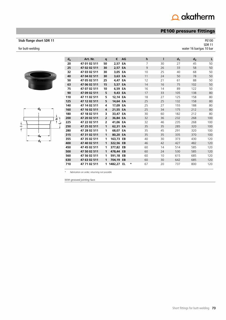
73
PE100 pressure fittings
Short fittings for butt-welding
With grooved jointing face.
Stub flange short SDR 11 PE100SDR 11
for butt-welding water 16 bar/gas 10 bar
de Art. Nr. q € AG h l d1 d2 L
20 47 01 02 511 50 2,57 EA 7 30 27 45 5025 47 02 02 511 30 2,57 EA 9 26 33 58 5032 47 03 02 511 30 3,05 EA 10 25 40 68 5040 47 04 02 511 30 3,63 EA 11 24 50 78 5050 47 05 02 511 25 4,47 EA 12 21 61 88 5063 47 06 02 511 15 5,57 EA 14 16 75 102 5075 47 07 02 511 10 6,59 EA 16 14 89 122 5090 47 09 02 511 5 9,43 EA 17 33 105 138 80
110 47 11 02 511 5 12,14 EA 18 27 125 158 80125 47 12 02 511 5 14,64 EA 25 25 132 158 80140 47 14 02 511 4 17,09 EA 25 27 155 188 80160 47 16 02 511 4 21,55 EA 25 34 175 212 80180 47 18 02 511 3 33,47 EA 30 60 182 212 80200 47 20 02 511 2 36,84 EA 32 36 232 268 100225 47 22 02 511 2 41,06 EA 32 46 235 268 100250 47 25 02 511 1 62,31 EA 35 35 285 320 100280 47 28 02 511 1 68,07 EA 35 45 291 320 100315 47 31 02 511 1 80,20 EA 35 35 335 370 100355 47 35 02 511 1 163,73 EB 40 30 373 430 120400 47 40 02 511 1 322,56 EB 46 42 427 482 120450 47 45 02 511 1 377,82 EB 60 14 514 585 120500 47 50 02 511 1 478,44 EB 60 24 530 585 120560 47 56 02 511 1 591,18 EB 60 10 615 685 120630 47 63 02 511 1 704,19 EB 60 30 642 685 120710 47 71 02 511 1 1482,27 EL *
* fabrication on order, returning not possible
67 20 737 800 120
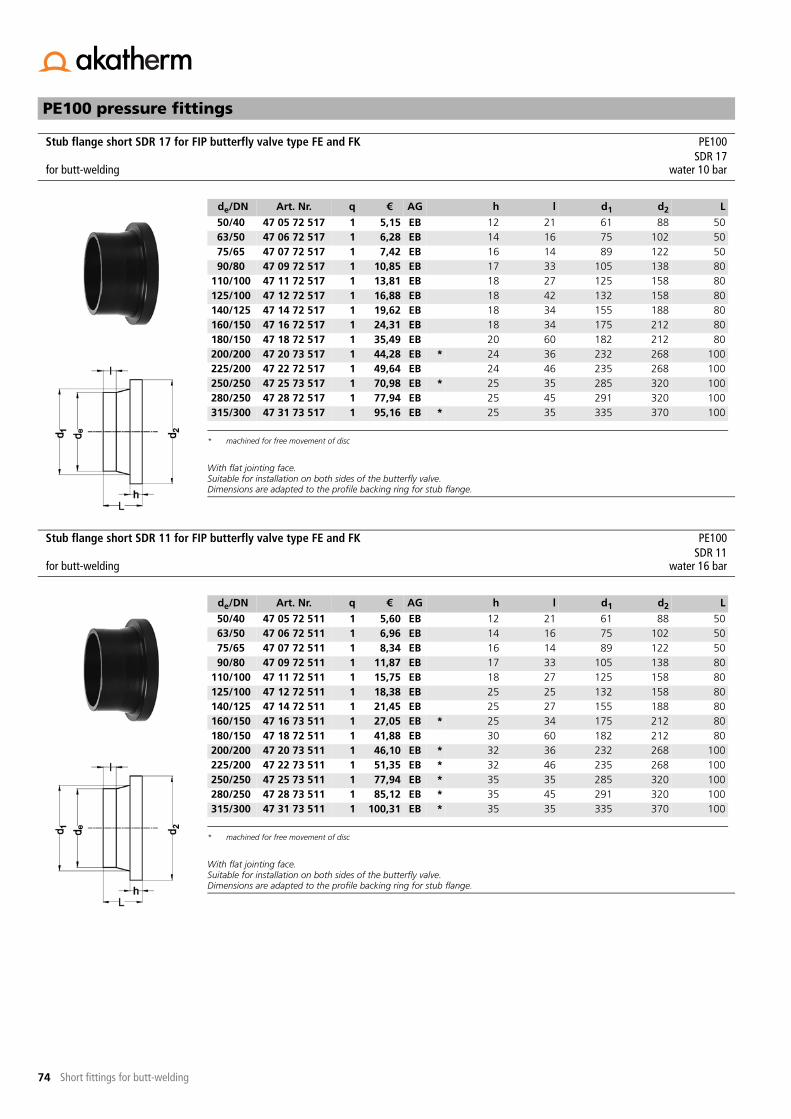
74
PE100 pressure fittings
Short fittings for butt-welding
With flat jointing face.Suitable for installation on both sides of the butterfly valve. Dimensions are adapted to the profile backing ring for stub flange.
With flat jointing face.Suitable for installation on both sides of the butterfly valve.Dimensions are adapted to the profile backing ring for stub flange.
Stub flange short SDR 17 for FIP butterfly valve type FE and FK PE100SDR 17
for butt-welding water 10 bar
de/DN Art. Nr. q € AG h l d1 d2 L
50/40 47 05 72 517 1 5,15 EB 12 21 61 88 5063/50 47 06 72 517 1 6,28 EB 14 16 75 102 5075/65 47 07 72 517 1 7,42 EB 16 14 89 122 5090/80 47 09 72 517 1 10,85 EB 17 33 105 138 80
110/100 47 11 72 517 1 13,81 EB 18 27 125 158 80125/100 47 12 72 517 1 16,88 EB 18 42 132 158 80140/125 47 14 72 517 1 19,62 EB 18 34 155 188 80160/150 47 16 72 517 1 24,31 EB 18 34 175 212 80180/150 47 18 72 517 1 35,49 EB 20 60 182 212 80200/200 47 20 73 517 1 44,28 EB *
* machined for free movement of disc
24 36 232 268 100225/200 47 22 72 517 1 49,64 EB 24 46 235 268 100250/250 47 25 73 517 1 70,98 EB * 25 35 285 320 100280/250 47 28 72 517 1 77,94 EB 25 45 291 320 100315/300 47 31 73 517 1 95,16 EB * 25 35 335 370 100
Stub flange short SDR 11 for FIP butterfly valve type FE and FK PE100SDR 11
for butt-welding water 16 bar
de/DN Art. Nr. q € AG h l d1 d2 L
50/40 47 05 72 511 1 5,60 EB 12 21 61 88 5063/50 47 06 72 511 1 6,96 EB 14 16 75 102 5075/65 47 07 72 511 1 8,34 EB 16 14 89 122 5090/80 47 09 72 511 1 11,87 EB 17 33 105 138 80
110/100 47 11 72 511 1 15,75 EB 18 27 125 158 80125/100 47 12 72 511 1 18,38 EB 25 25 132 158 80140/125 47 14 72 511 1 21,45 EB 25 27 155 188 80160/150 47 16 73 511 1 27,05 EB *
* machined for free movement of disc
25 34 175 212 80180/150 47 18 72 511 1 41,88 EB 30 60 182 212 80200/200 47 20 73 511 1 46,10 EB * 32 36 232 268 100225/200 47 22 73 511 1 51,35 EB * 32 46 235 268 100250/250 47 25 73 511 1 77,94 EB * 35 35 285 320 100280/250 47 28 73 511 1 85,12 EB * 35 45 291 320 100315/300 47 31 73 511 1 100,31 EB * 35 35 335 370 100

75
PE100 pressure fittings
Short fittings for butt-welding
With flat jointing face.Suitable for installation on entrance side. Install stub flange extended short CR/FR on exit side.Dimensions are adapted to the profile backing ring for stub flange.
With flat jointing face.Suitable for installation on entrance side. Install stub flange extended short CR/FR on exit side. Dimensions are adapted to the profile backing ring for stub flange.
Stub flange short SDR 17 for entrance side FIP check valve type CR and FR PE100SDR 17
for butt-welding water 10 bar
de/DN Art. Nr. q € AG h l d1 d2 L
50/40 47 05 72 517 1 5,15 EB 12 21 61 88 5063/50 47 06 72 517 1 6,28 EB 14 16 75 102 5075/65 47 07 72 517 1 7,42 EB 16 14 89 122 5090/80 47 09 72 517 1 10,85 EB 17 33 105 138 80
110/100 47 11 72 517 1 13,81 EB 18 27 125 158 80125/100 47 12 72 517 1 16,88 EB 18 42 132 158 80140/125 47 14 72 517 1 19,62 EB 18 34 155 188 80160/150 47 16 72 517 1 24,31 EB 18 34 175 212 80180/150 47 18 72 517 1 35,49 EB 20 60 182 212 80200/200 47 20 72 517 1 44,28 EB 24 36 232 268 100225/200 47 22 72 517 1 49,64 EB 24 46 235 268 100250/250 47 25 72 517 1 70,98 EB 25 35 285 320 100280/250 47 28 72 517 1 77,94 EB 25 45 291 320 100315/300 47 31 72 517 1 95,16 EB 25 35 335 370 100
Stub flange short SDR 11 for entrance side FIP check valve type CR and FR PE100SDR 11
for butt-welding water 16 bar
de/DN Art. Nr. q € AG h l d1 d2 L
50/40 47 05 72 511 1 5,60 EB 12 21 61 88 5063/50 47 06 72 511 1 6,96 EB 14 16 75 102 5075/65 47 07 72 511 1 8,34 EB 16 14 89 122 5090/80 47 09 72 511 1 11,87 EB 17 33 105 138 80
110/100 47 11 72 511 1 15,75 EB 18 27 125 158 80125/100 47 12 72 511 1 18,38 EB 25 25 132 158 80140/125 47 14 72 511 1 21,45 EB 25 27 155 188 80160/150 47 16 72 511 1 27,05 EB 25 34 175 212 80180/150 47 18 72 511 1 41,88 EB 30 60 182 212 80200/200 47 20 72 511 1 46,10 EB 32 36 232 268 100225/200 47 22 72 511 1 51,35 EB 32 46 235 268 100250/250 47 25 72 511 1 77,94 EB 35 35 285 320 100280/250 47 28 72 511 1 85,12 EB 35 45 291 320 100315/300 47 31 72 511 1 100,31 EB 35 35 335 370 100

76
PE100 pressure fittings
Short fittings for butt-welding
With flat jointing face. Extended for free movement of disc.Suitable for installation on exit side. Install stub flange short CR/FR on entrance side.Dimensions are adapted to the profile backing ring for stub flange. Fabrication on order.
With flat jointing face. Extended for free movement of disc.Suitable for installation on exit side. Install stub flange short CR/FR on entrance side. Dimensions are adapted to the profile backing ring for stub flange. Fabrication on order.
Stub flange extended short SDR 17 for exit side FIP check valve type CR and FR PE100SDR 17
for butt-welding water 10 bar
de/DN Art. Nr. q € AG h l d1 d2 L R
50/40 47 05 71 517 1 42,00 EC 12 20 61 90 50 363/50 47 06 71 517 1 48,71 EC 14 20 75 105 54 475/65 47 07 71 517 1 60,31 EC 16 20 89 125 58 490/80 47 09 71 517 1 63,98 EC 17 40 105 138 92 4
110/100 47 11 71 517 1 80,22 EC 18 40 125 160 92 4140/125 47 14 71 517 1 119,53 EC 18 40 155 190 100 4160/150 47 16 71 517 1 151,53 EC 18 40 175 215 120 4225/200 47 22 71 517 1 256,41 EC 24 40 235 270 165 4280/250 47 28 71 517 1 381,66 EC 25 40 291 325 195 6315/300 47 31 71 517 1 602,92 EC 25 40 335 375 250 6
Stub flange extended short SDR 11 for exit side FIP check valve type CR and FR PE100SDR 11
for butt-welding water 16 bar
de/DN Art. Nr. q € AG h l d1 d2 L R
50/40 47 05 71 511 1 42,00 EC 12 20 61 90 50 363/50 47 06 71 511 1 48,71 EC 14 20 75 105 56 475/65 47 07 71 511 1 60,31 EC 16 20 89 125 65 490/80 47 09 71 511 1 63,98 EC 17 35 105 138 92 4
110/100 47 11 71 511 1 80,22 EC 18 35 125 160 92 4140/125 47 14 71 511 1 119,53 EC 18 40 155 190 110 4160/150 47 16 71 511 1 151,53 EC 18 40 175 215 120 4225/200 47 22 71 511 1 256,41 EC 26 56 235 270 180 4280/250 47 28 71 511 1 381,66 EC 35 40 291 325 220 6315/300 47 31 71 511 1 602,92 EC 35 40 335 375 270 6
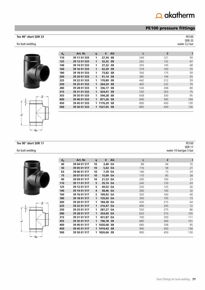
77
PE100 pressure fittings
Short fittings for butt-welding
Tee 90° short SDR 33 PE100SDR 33
for butt-welding water 3,2 bar
de Art. Nr. q € AG L Z l
110 39 11 01 533 1 27,34 EB 249 121 50125 39 12 01 533 1 32,32 EB 262 132 47140 39 14 01 533 1 37,32 EB 293 145 48160 39 16 01 533 1 62,29 EB 318 160 55180 39 18 01 533 1 73,82 EB 356 175 59200 39 20 01 533 1 91,14 EB 385 194 55225 39 22 01 533 1 170,89 EB 442 212 59250 39 25 01 533 1 264,24 EB 465 232 70280 39 28 01 533 1 336,17 EB 536 268 80315 39 31 01 533 1 424,41 EB 530 263 75355 39 35 01 533 1 594,28 EB 658 330 95400 39 40 01 533 1 871,26 EB 690 345 104450 39 45 01 533 1 1176,29 EB 890 450 130500 39 50 01 533 1 1527,05 EB 895 450 130
Tee 90° short SDR 17 PE100SDR 17
for butt-welding water 10 bar/gas 5 bar
de Art. Nr. q € AG L Z l
40 39 04 01 517 10 3,40 EA 88 44 1650 39 05 01 517 10 5,42 EA 116 58 2163 39 06 01 517 10 7,39 EA 146 73 2475 39 07 01 517 10 15,09 EA 170 85 2890 39 09 01 517 10 21,53 EA 200 100 23
110 39 11 01 517 5 35,74 EA 240 120 43125 39 12 01 517 5 49,52 EA 250 125 26140 39 14 01 517 4 58,46 EA 280 140 32160 39 16 01 517 2 109,92 EA 320 160 40180 39 18 01 517 1 135,03 EA 390 195 73200 39 20 01 517 1 184,38 EA 430 215 64225 39 22 01 517 1 216,47 EA 490 245 72250 39 25 01 517 1 287,27 EA 550 275 86280 39 28 01 517 1 324,69 EA 620 310 105315 39 31 01 517 1 431,87 EA 700 350 111355 39 35 01 517 1 746,78 EB 680 340 101400 39 40 01 517 1 1020,68 EB 680 338 95450 39 45 01 517 1 1419,43 EB 900 450 130500 39 50 01 517 1 1826,66 EB 900 450 130

78
-- to be continued --
PE100 pressure fittings
Short fittings for butt-welding
Tee 90° short SDR 11 PE100SDR 11
for butt-welding water 16 bar/gas 10 bar
de Art. Nr. q € AG L Z l
20 39 01 01 511 30 2,27 EA 50 25 825 39 02 01 511 30 2,27 EA 60 30 1032 39 03 01 511 20 2,86 EA 80 40 1240 39 04 01 511 10 4,55 EA 88 44 1650 39 05 01 511 10 6,13 EA 116 58 2163 39 06 01 511 10 9,51 EA 146 73 2475 39 07 01 511 10 19,15 EA 170 85 2890 39 09 01 511 10 28,61 EA 200 100 23
110 39 11 01 511 5 42,01 EA 240 120 43125 39 12 01 511 5 57,87 EA 250 125 26140 39 14 01 511 4 73,32 EA 280 140 32160 39 16 01 511 2 123,32 EA 320 160 40180 39 18 01 511 1 158,07 EA 390 195 73200 39 20 01 511 1 226,52 EA 430 215 64225 39 22 01 511 1 269,40 EA 490 245 72250 39 25 01 511 1 342,73 EA 550 275 86280 39 28 01 511 1 463,37 EA 620 310 105315 39 31 01 511 1 658,23 EA 700 350 111355 39 35 01 511 1 884,67 EB 680 340 101400 39 40 01 511 1 1320,97 EB 680 338 95450 39 45 01 511 1 1745,21 EB 900 450 130500 39 50 01 511 1 2230,49 EB 900 450 130
Tee 90° reduced short SDR 17 PE100with reduced branch SDR 17for butt-welding water 10 bar/gas 5 bar
de1/de2 Art. Nr. q € AG L Z l1 l290/32 28 09 03 517 10 22,89 EB 213 85 53 2390/50 28 09 05 517 10 23,51 EB 214 93 53 28
110/32 28 11 03 517 5 38,34 EB 244 94 66 22110/50 28 11 05 517 5 36,02 EB 238 103 66 27110/63 28 11 06 517 5 46,87 EB 240 105 48 32110/90 28 11 09 517 5 46,87 EB 240 115 48 38125/63 28 12 06 517 5 54,13 EB 264 110 70 31125/90 28 12 09 517 5 54,13 EB 265 124 72 32140/63 28 14 06 517 4 62,62 EB 300 120 83 32140/75 28 14 07 517 4 62,90 EB 300 130 81 35140/90 28 14 09 517 4 63,92 EB 300 130 81 41140/110 28 14 11 517 4 65,24 EB 300 137 50 47160/110 28 16 11 517 2 127,67 EB 320 145 56 38160/125 28 16 12 517 2 127,67 EB 315 150 58 47180/63 28 18 06 517 1 144,41 EB 358 134 125 30180/75 28 18 07 517 1 144,41 EB 360 140 112 30180/110 28 18 11 517 1 148,82 EB 365 158 106 48180/125 28 18 12 517 1 148,82 EB 358 160 92 50200/63 28 20 06 517 1 181,35 EB 382 145 143 31200/125 28 20 12 517 1 203,54 EB 390 165 114 43200/160 28 20 16 517 1 206,07 EB 390 165 98 60225/110 28 22 11 517 1 255,40 EB 440 264 89 89

79
Tee 90° reduced short SDR 17 - continuation -PE100 pressure fittings
Short fittings for butt-welding
225/125 28 22 12 517 1 255,40 EB 445 180 135 40225/160 28 22 16 517 1 255,40 EB 470 200 89 60250/110 28 25 11 517 1 310,47 EB 455 197 135 38250/160 28 25 16 517 1 316,75 EB 455 219 110 58
de1/de2 Art. Nr. q € AG L Z l1 l2
Tee 90° reduced short SDR 11 PE100with reduced branch SDR 11for butt-welding water 16 bar/gas 10 bar
de1/de2 Art. Nr. q € AG L Z l1 l290/32 28 09 03 511 10 30,50 EB 213 85 53 2390/50 28 09 05 511 10 31,33 EB 213 90 53 28
110/32 28 11 03 511 5 45,01 EB 244 94 66 22110/50 28 11 05 511 5 45,94 EB 244 103 66 27110/63 28 11 06 511 5 64,05 EB 240 105 48 32110/90 28 11 09 511 5 64,05 EB 240 115 48 38125/63 28 12 06 511 5 64,28 EB 278 112 70 31125/90 28 12 09 511 5 64,28 EB 265 124 72 32140/63 28 14 06 511 4 80,65 EB 305 120 83 32140/75 28 14 07 511 4 80,65 EB 305 130 81 35140/90 28 14 09 511 4 81,95 EB 305 130 81 41140/110 28 14 11 511 4 81,95 EB 305 140 50 47160/110 28 16 11 511 2 144,25 EB 320 145 56 38160/125 28 16 12 511 2 144,25 EB 325 150 58 47180/63 28 18 06 511 1 168,86 EB 358 134 125 30180/75 28 18 07 511 1 168,86 EB 352 140 112 30180/110 28 18 11 511 1 174,27 EB 365 158 106 48180/125 28 18 12 511 1 174,27 EB 366 166 92 50200/63 28 20 06 511 1 242,12 EB 382 145 143 31200/125 28 20 12 511 1 258,70 EB 390 165 114 43200/160 28 20 16 511 1 252,67 EB 390 180 98 60225/110 28 22 11 511 1 306,19 EB 440 264 89 88225/125 28 22 12 511 1 306,19 EB 456 178 135 40225/160 28 22 16 511 1 318,27 EB 470 200 89 60250/110 28 25 11 511 1 401,60 EB 463 197 135 38250/160 28 25 16 511 1 396,00 EB 458 219 110 58

80
-- to be continued --
PE100 pressure fittings
Short fittings for butt-welding
Tee 90° reduced machined short SDR17 - pressure class conform PE100with reduced branch SDR 17for butt-welding water 10 bar/gas 5 bar
de1/de2 Art. Nr. q € AG L Z
280/63 40 28 06 517 1 650,86 EC 270 365280/75 40 28 07 517 1 667,12 EC 280 365280/90 40 28 09 517 1 694,16 EC 295 365280/110 40 28 11 517 1 728,29 EC 315 365280/125 40 28 12 517 1 766,29 EC 330 365280/140 40 28 14 517 1 802,15 EC 345 365280/160 40 28 16 517 1 923,98 EC 365 365280/180 40 28 18 517 1 1008,71 EC 385 365280/200 40 28 20 517 1 1092,54 EC 405 365280/225 40 28 22 517 1 1349,19 EC 430 365315/75 40 31 07 517 1 712,14 EC 280 380315/90 40 31 09 517 1 734,67 EC 295 380315/110 40 31 11 517 1 937,59 EC 315 380315/125 40 31 12 517 1 980,88 EC 330 380315/140 40 31 14 517 1 914,01 EC 345 380315/160 40 31 16 517 1 1087,04 EC 365 380315/180 40 31 18 517 1 1151,06 EC 385 380315/200 40 31 20 517 1 1207,86 EC 405 380315/225 40 31 22 517 1 1577,17 EC 430 380315/250 40 31 25 517 1 1703,27 EC 455 380355/90 40 35 09 517 1 861,68 EC 305 400355/110 40 35 11 517 1 943,59 EC 325 400355/125 40 35 12 517 1 980,56 EC 340 400355/140 40 35 14 517 1 1039,59 EC 355 400355/160 40 35 16 517 1 1277,14 EC 375 400355/180 40 35 18 517 1 1350,20 EC 395 400355/200 40 35 20 517 1 1431,29 EC 415 400355/225 40 35 22 517 1 1525,99 EC 440 400355/250 40 35 25 517 1 1643,92 EC 465 400355/280 40 35 28 517 1 2088,35 EC 500 400400/110 40 40 11 517 1 1132,06 EC 325 425400/125 40 40 12 517 1 1183,57 EC 340 425400/140 40 40 14 517 1 1233,14 EC 355 425400/160 40 40 16 517 1 1279,98 EC 375 425400/180 40 40 18 517 1 1589,07 EC 395 425400/200 40 40 20 517 1 1676,52 EC 415 425400/225 40 40 22 517 1 1770,12 EC 440 425400/250 40 40 25 517 1 1906,26 EC 465 425400/280 40 40 28 517 1 2361,44 EC 500 425400/315 40 40 31 517 1 2589,44 EC 535 425450/125 40 45 12 517 1 1220,34 EC 340 450450/140 40 45 14 517 1 1271,98 EC 355 450450/160 40 45 16 517 1 1342,17 EC 375 450450/180 40 45 18 517 1 1607,96 EC 395 450450/200 40 45 20 517 1 1692,71 EC 415 450450/225 40 45 22 517 1 1773,78 EC 440 450450/250 40 45 25 517 1 2152,35 EC 465 450450/280 40 45 28 517 1 2317,14 EC 500 450450/315 40 45 31 517 1 2538,94 EC 535 450450/355 40 45 35 517 1 3360,71 EC 575 450500/140 40 50 14 517 1 1533,99 EC 355 475500/160 40 50 16 517 1 1595,45 EC 375 475500/180 40 50 18 517 1 1681,82 EC 395 475500/200 40 50 20 517 1 1770,12 EC 415 475500/225 40 50 22 517 1 2555,10 EC 440 475500/250 40 50 25 517 1 2743,36 EC 465 475

81
Tee 90° reduced machined short SDR17 - pressure class conform - continuation -PE100 pressure fittings
Short fittings for butt-welding
Pressure rating guaranteed, branch extended with pipe.Fabrication on order, returning not possible.
500/280 40 50 28 517 1 2767,96 EC 500 475500/315 40 50 31 517 1 3195,60 EC 535 475500/355 40 50 35 517 1 3480,30 EC 575 475500/400 40 50 40 517 1 3967,07 EC 620 475560/160 40 56 16 517 1 2038,66 EC 375 500560/180 40 56 18 517 1 2153,97 EC 395 500560/200 40 56 20 517 1 2238,51 EC 415 500560/225 40 56 22 517 1 2427,18 EC 440 500560/250 40 56 25 517 1 2504,50 EC 465 500560/280 40 56 28 517 1 2727,01 EC 500 500560/315 40 56 31 517 1 2099,11 EC 535 500560/355 40 56 35 517 1 3820,05 EC 575 500560/400 40 56 40 517 1 4319,43 EC 620 500560/450 40 56 45 517 1 5508,78 EC 670 500560/560 40 56 56 517 1 8500,36 EC 780 500630/180 40 63 18 517 1 2314,41 EC 395 540630/200 40 63 20 517 1 2407,26 EC 415 540630/225 40 63 22 517 1 2556,73 EC 440 540630/250 40 63 25 517 1 2759,42 EC 465 540630/280 40 63 28 517 1 2963,95 EC 500 540630/315 40 63 31 517 1 3906,82 EC 535 540630/355 40 63 35 517 1 4232,05 EC 575 540630/400 40 63 40 517 1 4789,84 EC 620 540630/450 40 63 45 517 1 5757,61 EC 670 540630/500 40 63 50 517 1 7398,59 EC 720 540630/630 40 63 63 517 1 13153,14 EC 850 540710/180 40 71 18 517 1 3406,13 EC 395 620710/200 40 71 20 517 1 3522,26 EC 415 620710/225 40 71 22 517 1 3635,12 EC 440 620710/250 40 71 25 517 1 3850,22 EC 465 620710/280 40 71 28 517 1 4033,10 EC 500 620710/315 40 71 31 517 1 4517,05 EC 535 620710/355 40 71 35 517 1 4840,75 EC 575 620710/400 40 71 40 517 1 5293,59 EC 620 620710/450 40 71 45 517 1 6142,17 EC 670 620710/500 40 71 50 517 1 7195,07 EC 720 620710/560 40 71 56 517 1 8369,50 EC 780 620710/710 40 71 71 517 1 15261,18 EC 950 650
de1/de2 Art. Nr. q € AG L Z

82
-- to be continued --
PE100 pressure fittings
Short fittings for butt-welding
Tee 90° reduced machined short SDR11 - pressure class conform PE100with reduced branch SDR 11for butt-welding water 16 bar/gas 10 bar
de1/de2 Art. Nr. q € AG L Z
280/63 40 28 06 511 1 676,37 EC 270 365280/75 40 28 07 511 1 693,24 EC 280 365280/90 40 28 09 511 1 721,29 EC 295 365280/110 40 28 11 511 1 756,83 EC 315 365280/125 40 28 12 511 1 796,35 EC 330 365280/140 40 28 14 511 1 833,55 EC 345 365280/160 40 28 16 511 1 960,14 EC 365 365280/180 40 28 18 511 1 1048,24 EC 385 365280/200 40 28 20 511 1 1135,31 EC 405 365280/225 40 28 22 511 1 1402,12 EC 430 365315/75 40 31 07 511 1 739,97 EC 280 380315/90 40 31 09 511 1 763,44 EC 295 380315/110 40 31 11 511 1 974,27 EC 315 380315/125 40 31 12 511 1 1019,17 EC 330 380315/140 40 31 14 511 1 1066,01 EC 345 380315/160 40 31 16 511 1 1129,61 EC 365 380315/180 40 31 18 511 1 1196,16 EC 385 380315/200 40 31 20 511 1 1255,10 EC 405 380315/225 40 31 22 511 1 1639,06 EC 430 380315/250 40 31 25 511 1 1770,02 EC 455 380355/90 40 35 09 511 1 895,52 EC 305 400355/110 40 35 11 511 1 980,56 EC 325 400355/125 40 35 12 511 1 1019,07 EC 340 400355/140 40 35 14 511 1 1080,33 EC 355 400355/160 40 35 16 511 1 1327,24 EC 375 400355/180 40 35 18 511 1 1403,04 EC 395 400355/200 40 35 20 511 1 1487,36 EC 415 400355/225 40 35 22 511 1 1585,71 EC 440 400355/250 40 35 25 511 1 1708,35 EC 465 400355/280 40 35 28 511 1 2170,13 EC 500 400400/110 40 40 11 511 1 1176,46 EC 325 425400/125 40 40 12 511 1 1229,80 EC 340 425400/140 40 40 14 511 1 1281,50 EC 355 425400/160 40 40 16 511 1 1330,08 EC 375 425400/180 40 40 18 511 1 1651,35 EC 395 425400/200 40 40 20 511 1 1742,18 EC 415 425400/225 40 40 22 511 1 1839,41 EC 440 425400/250 40 40 25 511 1 1980,85 EC 465 425400/280 40 40 28 511 1 2454,00 EC 500 425400/315 40 40 31 511 1 2690,93 EC 535 425450/125 40 45 12 511 1 1268,20 EC 340 450450/140 40 45 14 511 1 1321,85 EC 355 450450/160 40 45 16 511 1 1394,69 EC 375 450450/180 40 45 18 511 1 1670,95 EC 395 450450/200 40 45 20 511 1 1759,04 EC 415 450450/225 40 45 22 511 1 1843,16 EC 440 450450/250 40 45 25 511 1 2236,68 EC 465 450450/280 40 45 28 511 1 2408,07 EC 500 450450/315 40 45 31 511 1 2638,41 EC 535 450450/355 40 45 35 511 1 3492,38 EC 575 450500/140 40 50 14 511 1 1593,93 EC 355 475500/160 40 50 16 511 1 1657,85 EC 375 475500/180 40 50 18 511 1 1747,66 EC 395 475500/200 40 50 20 511 1 1839,41 EC 415 475500/225 40 50 22 511 1 2655,29 EC 440 475500/250 40 50 25 511 1 2850,88 EC 465 475

83
Tee 90° reduced machined short SDR11 - pressure class conform - continuation -PE100 pressure fittings
Short fittings for butt-welding
Pressure rating guaranteed, branch extended with pipe.Fabrication on order, returning not possible.
500/280 40 50 28 511 1 2876,37 EC 500 475500/315 40 50 31 511 1 3320,78 EC 535 475500/355 40 50 35 511 1 3616,63 EC 575 475500/400 40 50 40 511 1 4122,43 EC 620 475560/160 40 56 16 511 1 2118,51 EC 375 500560/180 40 56 18 511 1 2238,40 EC 395 500560/200 40 56 20 511 1 2326,19 EC 415 500560/225 40 56 22 511 1 2522,18 EC 440 500560/250 40 56 25 511 1 2602,64 EC 465 500560/280 40 56 28 511 1 2833,91 EC 500 500560/315 40 56 31 511 1 3237,26 EC 535 500560/355 40 56 35 511 1 3969,81 EC 575 500560/400 40 56 40 511 1 4488,70 EC 620 500560/450 40 56 45 511 1 5724,59 EC 670 500560/560 40 56 56 511 1 8833,41 EC 780 500630/180 40 63 18 511 1 2405,03 EC 395 540630/200 40 63 20 511 1 2501,55 EC 415 540630/225 40 63 22 511 1 2656,91 EC 440 540630/250 40 63 25 511 1 2867,52 EC 465 540630/280 40 63 28 511 1 3080,08 EC 500 540630/315 40 63 31 511 1 4059,83 EC 535 540630/355 40 63 35 511 1 4397,76 EC 575 540630/400 40 63 40 511 1 4977,50 EC 620 540630/450 40 63 45 511 1 5983,27 EC 670 540630/500 40 63 50 511 1 7688,47 EC 720 540630/630 40 63 63 511 1 13668,48 EC 850 540710/180 40 71 18 511 1 3539,52 EC 395 620710/200 40 71 20 511 1 3660,23 EC 415 620710/225 40 71 22 511 1 3777,59 EC 440 620710/250 40 71 25 511 1 4001,11 EC 465 620710/280 40 71 28 511 1 4191,11 EC 500 620710/315 40 71 31 511 1 4694,04 EC 535 620710/355 40 71 35 511 1 5030,43 EC 575 620710/400 40 71 40 511 1 5500,96 EC 620 620710/450 40 71 45 511 1 5366,74 EC 670 620710/500 40 71 50 511 1 7476,91 EC 720 620710/560 40 71 56 511 1 8697,37 EC 780 620710/710 40 71 71 511 1 15859,12 EC 950 650
de1/de2 Art. Nr. q € AG L Z

84
PE100 pressure fittings
Short fittings for butt-welding
R � 1 x de
R � 1 x de
Bend 90° short SDR 33 PE100SDR 33
for butt-welding water 3,2 bar
de Art. Nr. q € AG Z l R
110 11 11 91 533 1 20,88 EB 120 10 110125 11 12 91 533 1 23,51 EB 140 15 125140 11 14 91 533 1 30,39 EB 150 10 140160 11 16 91 533 1 39,70 EB 180 25 155180 11 18 91 533 1 48,38 EB 200 25 175200 11 20 91 533 1 60,02 EB 220 23 197225 11 22 91 533 1 73,88 EB 250 20 230250 11 25 91 533 1 90,75 EB 290 25 265280 11 28 91 533 1 112,27 EB 290 10 280315 11 31 91 533 1 159,31 EB 340 40 300355 11 35 91 533 1 425,76 EB 340 40 300400 11 40 91 533 1 595,47 EB 345 45 300450 11 45 91 533 1 802,21 EB 450 50 400500 11 50 91 533 1 1118,11 EB 450 50 400
Bend 90° short SDR 17 PE100SDR 17
for butt-welding water 10 bar/gas 5 bar
de Art. Nr. q € AG Z l R
40 11 04 91 517 50 3,79 EA 51 7 4450 11 05 91 517 30 4,75 EA 62 7 5563 11 06 91 517 15 6,59 EA 77 8 6975 11 07 91 517 10 9,65 EA 85 10 7590 11 09 91 517 10 12,59 EA 100 10 90
110 11 11 91 517 10 26,52 EA 120 10 110125 11 12 91 517 5 33,72 EA 140 15 125140 11 14 91 517 5 48,97 EA 155 15 140160 11 16 91 517 5 54,01 EA 175 15 160180 11 18 91 517 2 66,77 EA 195 15 180200 11 20 91 517 1 82,69 EA 215 15 200225 11 22 91 517 1 101,92 EA 245 20 225250 11 25 91 517 1 172,12 EA 275 25 250280 11 28 91 517 1 223,69 EA 310 30 280315 11 31 91 517 1 309,03 EA 350 35 315355 11 35 91 517 1 563,15 EB 340 40 300400 11 40 91 517 1 784,19 EB 350 50 300450 11 45 91 517 1 1025,14 EB 450 50 400500 11 50 91 517 1 1293,62 EB 450 50 400
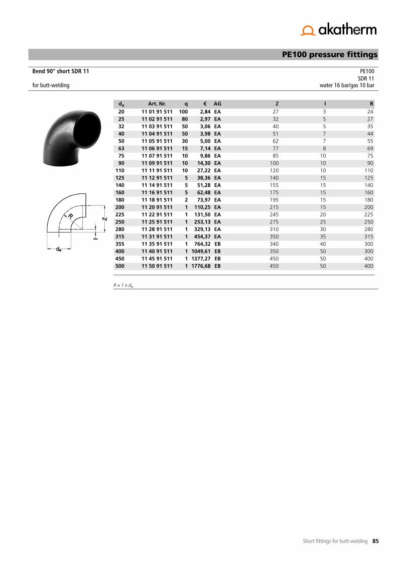
85
PE100 pressure fittings
Short fittings for butt-welding
R � 1 x de
Bend 90° short SDR 11 PE100SDR 11
for butt-welding water 16 bar/gas 10 bar
de Art. Nr. q € AG Z l R
20 11 01 91 511 100 2,84 EA 27 3 2425 11 02 91 511 80 2,97 EA 32 5 2732 11 03 91 511 50 3,06 EA 40 5 3540 11 04 91 511 50 3,98 EA 51 7 4450 11 05 91 511 30 5,00 EA 62 7 5563 11 06 91 511 15 7,14 EA 77 8 6975 11 07 91 511 10 9,86 EA 85 10 7590 11 09 91 511 10 14,30 EA 100 10 90
110 11 11 91 511 10 27,22 EA 120 10 110125 11 12 91 511 5 38,36 EA 140 15 125140 11 14 91 511 5 51,28 EA 155 15 140160 11 16 91 511 5 62,48 EA 175 15 160180 11 18 91 511 2 73,97 EA 195 15 180200 11 20 91 511 1 110,25 EA 215 15 200225 11 22 91 511 1 131,50 EA 245 20 225250 11 25 91 511 1 253,13 EA 275 25 250280 11 28 91 511 1 329,13 EA 310 30 280315 11 31 91 511 1 454,37 EA 350 35 315355 11 35 91 511 1 764,32 EB 340 40 300400 11 40 91 511 1 1049,61 EB 350 50 300450 11 45 91 511 1 1377,27 EB 450 50 400500 11 50 91 511 1 1776,68 EB 450 50 400

86
-- to be continued --
PE100 pressure fittings
Short fittings for butt-welding
Reducer concentric DIN short SDR 33 PE100SDR 33
for butt-welding water 3,2 bar
de1/de2 Art. Nr. q € AG L l1 l2200/140 17 20 14 533 1 66,85 EC 154 50 35200/160 17 20 16 533 1 59,13 EC 151 50 40200/180 17 20 18 533 1 52,95 EC 151 50 45225/140 17 22 14 533 1 79,86 EC 160 60 50225/160 17 22 16 533 1 68,53 EC 171 55 40225/180 17 22 18 533 1 65,25 EC 171 55 45225/200 17 22 20 533 1 57,49 EC 171 55 50250/160 17 25 16 533 1 91,52 EC 194 60 40250/180 17 25 18 533 1 84,70 EC 182 60 45250/200 17 25 20 533 1 77,94 EC 182 60 50250/225 17 25 22 533 1 73,84 EC 182 60 55280/200 17 28 20 533 1 101,96 EC 200 80 65280/225 17 28 22 533 1 95,04 EC 200 80 75280/250 17 28 25 533 1 91,52 EC 200 80 85315/200 17 31 20 533 1 130,10 EC 230 95 85315/225 17 31 22 533 1 115,10 EC 230 95 88315/250 17 31 25 533 1 104,83 EC 230 95 95315/280 17 31 28 533 1 98,22 EC 230 95 107
Reducer concentric DIN short SDR 17 PE100SDR 17
for butt-welding water 10 bar/gas 5 bar
de1/de2 Art. Nr. q € AG L l1 l250/32 17 05 03 517 25 5,02 EV 55 12 1250/40 17 05 04 517 25 5,02 EV 55 12 1263/32 17 06 03 517 15 6,03 EV 65 16 1263/40 17 06 04 517 15 6,03 EV 65 16 1263/50 17 06 05 517 15 6,03 EV 65 16 1275/32 17 07 03 517 5 7,79 EV 80 19 1275/40 17 07 04 517 5 7,79 EV 71 19 1275/50 17 07 05 517 5 7,79 EV 71 19 1275/63 17 07 06 517 5 7,79 EV 71 19 1690/50 17 09 05 517 5 8,69 EV 80 22 1290/63 17 09 06 517 5 8,69 EV 80 22 1690/75 17 09 07 517 5 8,69 EV 80 22 19
110/50 17 11 05 517 5 11,06 EV 105 28 12110/63 17 11 06 517 5 11,06 EV 97 28 16110/75 17 11 07 517 5 11,06 EV 97 28 19110/90 17 11 09 517 5 11,06 EV 97 28 22125/63 17 12 06 517 5 14,20 EV 112 30 16125/75 17 12 07 517 5 14,20 EV 108 32 19125/90 17 12 09 517 5 14,20 EV 108 32 22125/110 17 12 11 517 5 14,20 EV 108 32 28140/75 17 14 07 517 4 17,19 EV 123 35 19140/90 17 14 09 517 4 17,19 EV 115 35 22140/110 17 14 11 517 4 17,19 EV 115 35 28140/125 17 14 12 517 4 17,19 EV 115 35 32160/90 17 16 09 517 4 20,09 EV 135 40 22160/110 17 16 11 517 4 20,09 EV 124 40 28160/125 17 16 12 517 4 20,09 EV 124 40 32

87
-- to be continued --
Reducer concentric DIN short SDR 17 - continuation -PE100 pressure fittings
Short fittings for butt-welding
160/140 17 16 14 517 4 20,09 EV 124 40 35180/90 17 18 09 517 2 31,54 EV 157 45 22180/110 17 18 11 517 2 29,70 EV 157 45 28180/125 17 18 12 517 2 27,42 EV 136 45 32180/140 17 18 14 517 2 26,00 EV 136 45 35180/160 17 18 16 517 2 24,80 EV 136 45 40200/140 17 20 14 517 2 71,13 EV 154 50 35200/160 17 20 16 517 2 62,90 EV 151 50 40200/180 17 20 18 517 2 56,26 EV 151 50 45225/140 17 22 14 517 2 84,90 EV 160 60 50225/160 17 22 16 517 2 72,89 EV 171 55 40225/180 17 22 18 517 2 69,41 EV 171 55 45225/200 17 22 20 517 2 61,13 EV 171 55 50250/160 17 25 16 517 1 97,36 EV 194 60 40250/180 17 25 18 517 1 90,05 EV 182 60 45250/200 17 25 20 517 1 82,86 EV 182 60 50250/225 17 25 22 517 1 78,57 EV 182 60 55280/200 17 28 20 517 1 108,37 EV * 200 85 70280/225 17 28 22 517 1 101,05 EV * 200 85 72280/250 17 28 25 517 1 98,39 EV * 200 85 80315/200 17 31 20 517 1 138,31 EV * 230 95 85315/225 17 31 22 517 1 122,36 EV * 230 95 88315/250 17 31 25 517 1 111,51 EV * 230 95 95315/280 17 31 28 517 1 104,42 EV * 230 95 107
* machined version
de1/de2 Art. Nr. q € AG L l1 l2
Reducer concentric DIN short SDR 11 PE100SDR 11
for butt-welding water 16 bar/gas 10 bar
de1/de2 Art. Nr. q € AG L l1 l225/20 17 02 01 511 30 3,78 EV 37 12 1232/20 17 03 01 511 30 4,39 EV 43 12 1232/25 17 03 02 511 30 4,39 EV 43 12 1240/20 17 04 01 511 25 5,02 EV 50 12 1240/25 17 04 02 511 25 5,02 EV 50 12 1240/32 17 04 03 511 25 5,02 EV 50 12 1250/25 17 05 02 511 25 5,25 EV 55 12 1250/32 17 05 03 511 25 5,25 EV 55 12 1250/40 17 05 04 511 25 5,25 EV 55 12 1263/32 17 06 03 511 15 6,37 EV 65 16 1263/40 17 06 04 511 15 6,37 EV 65 16 1263/50 17 06 05 511 15 6,37 EV 65 16 1275/32 17 07 03 511 5 8,17 EV 80 19 1275/40 17 07 04 511 5 8,17 EV 71 19 1275/50 17 07 05 511 5 8,17 EV 71 19 1275/63 17 07 06 511 5 8,17 EV 71 19 1690/50 17 09 05 511 5 9,06 EV 80 22 1290/63 17 09 06 511 5 9,06 EV 80 22 1690/75 17 09 07 511 5 9,06 EV 80 22 19
110/50 17 11 05 511 5 11,57 EV 105 28 12110/63 17 11 06 511 5 11,57 EV 97 28 16110/75 17 11 07 511 5 11,57 EV 97 28 19110/90 17 11 09 511 5 11,57 EV 97 28 22125/63 17 12 06 511 5 14,88 EV 112 30 16125/75 17 12 07 511 5 14,88 EV 108 32 19125/90 17 12 09 511 5 14,88 EV 108 32 22125/110 17 12 11 511 5 14,88 EV 108 32 28

88
Reducer concentric DIN short SDR 11 - continuation -PE100 pressure fittings
Short fittings for butt-welding
140/75 17 14 07 511 4 18,01 EV 123 35 19140/90 17 14 09 511 4 18,01 EV 115 35 22140/110 17 14 11 511 4 18,01 EV 115 35 28140/125 17 14 12 511 4 18,01 EV 115 35 32160/90 17 16 09 511 4 21,13 EV 135 40 22160/110 17 16 11 511 4 21,13 EV 124 40 28160/125 17 16 12 511 4 21,13 EV 124 40 32160/140 17 16 14 511 4 21,13 EV 124 40 35180/90 17 18 09 511 2 33,15 EV 157 45 22180/110 17 18 11 511 2 31,20 EV 157 45 28180/125 17 18 12 511 2 28,77 EV 136 45 32180/140 17 18 14 511 2 27,30 EV 136 45 35180/160 17 18 16 511 2 26,07 EV 136 45 40200/140 17 20 14 511 2 74,64 EV 154 50 35200/160 17 20 16 511 2 66,03 EV 151 50 40200/180 17 20 18 511 2 59,10 EV 151 50 45225/140 17 22 14 511 2 89,18 EV 160 60 50225/160 17 22 16 511 2 76,51 EV 171 55 40225/180 17 22 18 511 2 72,84 EV 171 55 45225/200 17 22 20 511 2 64,19 EV 171 55 50250/160 17 25 16 511 1 102,19 EV 194 60 40250/180 17 25 18 511 1 94,52 EV 182 60 45250/200 17 25 20 511 1 87,00 EV 182 60 50250/225 17 25 22 511 1 82,43 EV 182 60 55280/200 17 28 20 511 1 113,84 EV * 200 85 70280/225 17 28 22 511 1 106,11 EV * 200 85 72280/250 17 28 25 511 1 102,19 EV * 200 85 80315/200 17 31 20 511 1 145,27 EV * 230 95 85315/225 17 31 22 511 1 128,50 EV * 230 95 88315/250 17 31 25 511 1 117,05 EV * 230 95 95315/280 17 31 28 511 1 109,67 EV * 230 95 107
* machined version
de1/de2 Art. Nr. q € AG L l1 l2

89
PE100 pressure fittings
Short fittings for butt-welding
Reducer concentric short SDR 33 PE100SDR 33
for butt-welding water 3,2 bar
de1/de2 Art. Nr. q € AG L l1 l2355/200 15 35 20 533 1 150,36 EC 160 57 40355/225 15 35 22 533 1 144,56 EC 140 57 40355/250 15 35 25 533 1 138,69 EC 130 54 40355/280 15 35 28 533 1 128,66 EC 120 53 40355/315 15 35 31 533 1 124,76 EC 110 53 40400/225 15 40 22 533 1 533,24 EC 160 64 40400/250 15 40 25 533 1 500,24 EC 150 61 40400/280 15 40 28 533 1 443,68 EC 140 60 40400/315 15 40 31 533 1 343,54 EC 120 50 40400/355 15 40 35 533 1 250,38 EC 110 51 40450/280 15 45 28 533 1 634,39 EC 160 65 40450/315 15 45 31 533 1 563,04 EC 140 55 40450/355 15 45 35 533 1 383,15 EC 130 57 40450/400 15 45 40 533 1 316,28 EC 120 60 40500/280 15 50 28 533 1 1110,21 EC 180 80 40500/315 15 50 31 533 1 774,15 EC 170 71 40500/355 15 50 35 533 1 676,65 EC 150 62 40500/400 15 50 40 533 1 574,28 EC 140 65 40500/450 15 50 45 533 1 511,44 EC 120 60 40560/355 15 56 35 533 1 1263,99 EC 170 75 40560/400 15 56 40 533 1 715,70 EC 160 68 40560/450 15 56 45 533 1 518,49 EC 140 62 40560/500 15 56 50 533 1 439,06 EC 130 67 40630/355 15 63 35 533 1 1419,88 EC 200 80 40630/400 15 63 40 533 1 1282,49 EC 190 78 40630/450 15 63 45 533 1 1030,63 EC 170 72 40630/500 15 63 50 533 1 617,39 EC 150 67 40630/560 15 63 56 533 1 572,55 EC 130 64 40710/500 15 71 50 533 1 1073,69 EC *
* fabrication on order, returning not possible
130 84 40710/560 15 71 56 533 1 959,77 EC * 170 81 40710/630 15 71 63 533 1 1708,84 EC * 140 71 40800/560 15 80 56 533 1 1708,84 EC * 200 85 40800/630 15 80 63 533 1 1211,99 EC * 180 85 40800/710 15 80 71 533 1 1093,12 EC * 150 78 40900/630 15 90 63 533 1 2522,28 EC * 220 96 40900/710 15 90 71 533 1 2185,09 EC * 190 89 40900/800 15 90 80 533 1 1737,79 EC * 160 85 401000/710 15 91 71 533 1 3441,27 EC * 220 101 401000/800 15 91 80 533 1 2891,09 EC * 180 86 401000/900 15 91 90 533 1 2339,79 EC * 140 75 401200/1000 15 92 91 533 1 3406,22 EC * 190 92 40

90
PE100 pressure fittings
Short fittings for butt-welding
Reducer concentric short SDR 17 PE100SDR 17
for butt-welding water 10 bar/gas 5 bar
de1/de2 Art. Nr. q € AG L l1 l2355/200 15 35 20 517 1 150,36 EC 160 57 40355/225 15 35 22 517 1 144,56 EC 140 57 40355/250 15 35 25 517 1 138,69 EC 130 54 40355/280 15 35 28 517 1 128,66 EC 120 53 40355/315 15 35 31 517 1 124,76 EC 110 53 40400/225 15 40 22 517 1 533,24 EC 160 64 40400/250 15 40 25 517 1 500,24 EC 150 61 40400/280 15 40 28 517 1 443,68 EC 140 60 40400/315 15 40 31 517 1 343,54 EC 120 50 40400/355 15 40 35 517 1 250,38 EC 110 51 40450/280 15 45 28 517 1 634,39 EC 160 65 40450/315 15 45 31 517 1 563,04 EC 140 55 40450/355 15 45 35 517 1 383,15 EC 130 57 40450/400 15 45 40 517 1 316,28 EC 120 60 40500/280 15 50 28 517 1 1110,21 EC 180 80 40500/315 15 50 31 517 1 774,15 EC 170 71 40500/355 15 50 35 517 1 676,65 EC 150 62 40500/400 15 50 40 517 1 574,28 EC 140 65 40500/450 15 50 45 517 1 511,44 EC 120 60 40560/355 15 56 35 517 1 1445,55 EC 170 75 40560/400 15 56 40 517 1 906,52 EC 160 68 40560/450 15 56 45 517 1 565,28 EC 140 62 40560/500 15 56 50 517 1 461,73 EC 130 67 40630/355 15 63 35 517 1 1561,82 EC 200 80 40630/400 15 63 40 517 1 1465,70 EC 190 78 40630/450 15 63 45 517 1 1216,66 EC 170 72 40630/500 15 63 50 517 1 801,58 EC 150 67 40630/560 15 63 56 517 1 620,25 EC 130 64 40710/500 15 71 50 517 1 2013,26 EC *
* fabrication on order, returning not possible
130 84 40710/560 15 71 56 517 1 1109,13 EC * 170 81 40710/630 15 71 63 517 1 1011,20 EC * 140 71 40800/560 15 80 56 517 1 1708,84 EC * 200 85 40800/630 15 80 63 517 1 1211,99 EC * 180 85 40800/710 15 80 71 517 1 1093,12 EC * 150 78 40900/630 15 90 63 517 1 2661,73 EC * 220 96 40900/710 15 90 71 517 1 2359,59 EC * 190 89 40900/800 15 90 80 517 1 1917,99 EC * 160 85 401000/710 15 91 71 517 1 3651,60 EC * 220 101 401000/800 15 91 80 517 1 3071,32 EC * 180 86 401000/900 15 91 90 517 1 2507,81 EC * 140 75 40

91
PE100 pressure fittings
Short fittings for butt-welding
Reducer concentric short SDR 11 PE100SDR 11
for butt-welding water 16 bar/gas 10 bar
de1/de2 Art. Nr. q € AG L l1 l2355/200 15 35 20 511 1 157,84 EC 160 57 40355/225 15 35 22 511 1 151,77 EC 140 57 40355/250 15 35 25 511 1 145,59 EC 130 54 40355/280 15 35 28 511 1 135,10 EC 120 53 40355/315 15 35 31 511 1 130,99 EC 110 53 40400/225 15 40 22 511 1 612,35 EC 160 64 40400/250 15 40 25 511 1 516,84 EC 150 61 40400/280 15 40 28 511 1 443,68 EC 140 60 40400/315 15 40 31 511 1 343,54 EC 120 50 40400/355 15 40 35 511 1 250,38 EC 110 51 40450/280 15 45 28 511 1 634,39 EC 160 65 40450/315 15 45 31 511 1 563,04 EC 140 55 40450/355 15 45 35 511 1 405,92 EC 130 57 40450/400 15 45 40 511 1 316,28 EC 120 60 40500/280 15 50 28 511 1 1110,21 EC 180 80 40500/315 15 50 31 511 1 774,15 EC 170 71 40500/355 15 50 35 511 1 740,80 EC 150 62 40500/400 15 50 40 511 1 618,73 EC 140 65 40500/450 15 50 45 511 1 560,50 EC 120 60 40560/355 15 56 35 511 1 1283,47 EC 170 75 40560/400 15 56 40 511 1 968,53 EC 160 68 40560/450 15 56 45 511 1 589,98 EC 140 62 40560/500 15 56 50 511 1 503,87 EC 130 67 40630/355 15 63 35 511 1 1786,33 EC 200 80 40630/400 15 63 40 511 1 1648,90 EC 190 78 40630/450 15 63 45 511 1 1309,20 EC 170 72 40630/500 15 63 50 511 1 892,24 EC 150 67 40630/560 15 63 56 511 1 706,17 EC 130 64 40

92
PE100 pressure fittings
Short fittings for butt-welding
Larger diameters on request.
Reducer eccentric short SDR 33 PE100SDR 33
for butt-welding water 3,2 bar
de1/de2 Art. Nr. q € AG L l1 l2160/90 31 16 09 533 1 139,67 EC 140 54 40160/110 31 16 11 533 1 121,33 EC 120 45 40160/125 31 16 12 533 1 110,43 EC 110 44 40160/140 31 16 14 533 1 98,25 EC 90 33 40180/110 31 18 11 533 1 165,83 EC 140 54 40180/125 31 18 12 533 1 147,13 EC 130 52 40180/140 31 18 14 533 1 134,04 EC 110 41 40180/160 31 18 16 533 1 123,15 EC 90 33 40200/125 31 20 12 533 1 178,72 EC 150 61 40200/140 31 20 14 533 1 161,47 EC 130 50 40200/160 31 20 16 533 1 142,39 EC 110 41 40200/180 31 20 18 533 1 134,22 EC 90 33 40225/140 31 22 14 533 1 224,30 EC 160 65 40225/160 31 22 16 533 1 209,94 EC 140 57 40225/180 31 22 18 533 1 183,25 EC 120 48 40225/200 31 22 20 533 1 164,55 EC 100 40 40250/160 31 25 16 533 1 266,27 EC 160 62 40250/180 31 25 18 533 1 256,81 EC 140 54 40250/200 31 25 20 533 1 234,64 EC 120 45 40250/225 31 25 22 533 1 195,41 EC 100 40 40280/180 31 28 18 533 1 299,13 EC 170 66 40280/200 31 28 20 533 1 275,16 EC 150 58 40280/225 31 28 22 533 1 247,72 EC 130 52 40280/250 31 28 25 533 1 212,31 EC 110 47 40315/200 31 31 20 533 1 331,26 EC 190 78 40315/225 31 31 22 533 1 293,32 EC 160 62 40315/250 31 31 25 533 1 256,61 EC 140 57 40315/280 31 31 28 533 1 233,02 EC 110 44 40

93
PE100 pressure fittings
Short fittings for butt-welding
Larger diameters on request.
Reducer eccentric short SDR 17 PE100SDR 17
for butt-welding water 10 bar/gas 5 bar
de1/de2 Art. Nr. q € AG L l1 l2160/90 31 16 09 517 1 139,70 EC 140 54 40160/110 31 16 11 517 1 121,33 EC 120 45 40160/125 31 16 12 517 1 110,43 EC 110 44 40160/140 31 16 14 517 1 98,25 EC 90 33 40180/110 31 18 11 517 1 165,83 EC 140 54 40180/125 31 18 12 517 1 147,13 EC 130 52 40180/140 31 18 14 517 1 134,04 EC 110 41 40180/160 31 18 16 517 1 123,15 EC 90 33 40200/125 31 20 12 517 1 178,72 EC 150 61 40200/140 31 20 14 517 1 161,47 EC 130 50 40200/160 31 20 16 517 1 142,39 EC 110 41 40200/180 31 20 18 517 1 134,22 EC 100 43 40225/140 31 22 14 517 1 224,30 EC 160 65 40225/160 31 22 16 517 1 209,94 EC 140 57 40225/180 31 22 18 517 1 183,25 EC 120 48 40225/200 31 22 20 517 1 164,55 EC 100 40 40250/160 31 25 16 517 1 266,27 EC 160 62 40250/180 31 25 18 517 1 256,08 EC 140 54 40250/200 31 25 20 517 1 234,64 EC 130 55 40250/225 31 25 22 517 1 195,41 EC 100 40 40280/180 31 28 18 517 1 299,13 EC 170 66 40280/200 31 28 20 517 1 275,16 EC 150 58 40280/225 31 28 22 517 1 247,72 EC 130 52 40280/250 31 28 25 517 1 212,31 EC 110 47 40315/200 31 31 20 517 1 331,26 EC 190 78 40315/225 31 31 22 517 1 293,32 EC 160 62 40315/250 31 31 25 517 1 256,61 EC 140 57 40315/280 31 31 28 517 1 233,02 EC 120 54 40

94
PE100 pressure fittings
Short fittings for butt-welding
Larger diameters on request.
Reducer eccentric short SDR 11 PE100SDR 11
for butt-welding water 16 bar/gas 10 bar
de1/de2 Art. Nr. q € AG L l1 l2160/90 31 16 09 511 1 146,75 EC 140 54 40160/110 31 16 11 511 1 131,67 EC 120 45 40160/125 31 16 12 511 1 117,69 EC 110 44 40160/140 31 16 14 511 1 103,70 EC 100 43 40180/110 31 18 11 511 1 173,99 EC 140 54 40180/125 31 18 12 511 1 154,57 EC 130 52 40180/140 31 18 14 511 1 143,30 EC 120 51 40180/160 31 18 16 511 1 131,86 EC 100 43 40200/125 31 20 12 511 1 187,61 EC 150 61 40200/140 31 20 14 511 1 170,54 EC 130 50 40200/160 31 20 16 511 1 151,47 EC 120 51 40200/180 31 20 18 511 1 143,30 EC 100 43 40225/140 31 22 14 511 1 235,74 EC 160 65 40225/160 31 22 16 511 1 218,12 EC 140 57 40225/180 31 22 18 511 1 189,79 EC 120 48 40225/200 31 22 20 511 1 172,73 EC 110 50 40250/160 31 25 16 511 1 279,34 EC 170 72 40250/180 31 25 18 511 1 269,34 EC 150 64 40250/200 31 25 20 511 1 243,93 EC 130 55 40250/225 31 25 22 511 1 210,14 EC 110 50 40280/180 31 28 18 511 1 314,20 EC 180 76 40280/200 31 28 20 511 1 280,41 EC 160 68 40280/225 31 28 22 511 1 255,36 EC 140 62 40280/250 31 28 25 511 1 226,49 EC 120 57 40315/200 31 31 20 511 1 347,80 EC 190 78 40315/225 31 31 22 511 1 307,47 EC 170 72 40315/250 31 31 25 511 1 266,62 EC 150 67 40315/280 31 31 28 511 1 241,36 EC 130 64 40

95
-- to be continued --
PE100 pressure fittings
Short fittings for butt-welding
End cap long/short SDR 17 PE100SDR 17
for butt-welding water 10 bar/gas 5 bar
de Art. Nr. q € AG L l
63 67 06 08 517 1 10,92 EF *
* long version
85 6275 67 07 08 517 1 16,92 EF * 95 6390 67 09 08 517 1 25,69 EF * 110 79
110 67 11 08 517 1 34,84 EF * 127 88125 67 12 08 517 1 37,64 EF * 124 95140 67 14 08 517 1 47,08 EF * 140 110160 67 16 08 517 1 52,75 EF * 152 121180 67 18 08 517 1 68,59 EF * 169 134200 67 20 08 517 1 85,44 EF * 184 140225 67 22 08 517 1 101,99 EF * 200 160250 67 25 08 517 1 137,49 EG * 230 152280 67 28 08 517 1 195,28 EG * 257 162315 67 31 08 517 1 261,15 EG * 262 167355 67 35 08 517 1 405,26 EG * 270 250400 67 40 08 517 1 711,34 EG * 275 250450 67 45 09 517 1 471,32 EC **
** short version, machinedfabrication on order, returning not possible
85 -500 67 50 09 517 1 656,90 EC ** 90 -560 67 56 09 517 1 1523,75 EC ** 100 -630 67 63 09 517 1 1739,45 EC ** 110 -710 67 71 09 517 1 3809,12 EC ** 110 -800 67 80 09 517 1 4172,26 EC ** 120 -
End cap long/short SDR 11 PE100SDR 11
for butt-welding water 16 bar/gas 10 bar
de Art. Nr. q € AG L l
20 67 01 08 511 1 3,69 EF * 45 3525 67 02 08 511 1 4,05 EF * 52 4032 67 03 08 511 1 5,11 EF * 58 4440 67 04 08 511 1 6,33 EF * 67 5050 67 05 08 511 1 8,28 EF * 75 5563 67 06 08 511 1 10,92 EF * 85 6275 67 07 08 511 1 16,92 EF * 95 6390 67 09 08 511 1 25,69 EF * 110 79
110 67 11 08 511 1 34,84 EF * 127 88125 67 12 08 511 1 37,64 EF * 124 95140 67 14 08 511 1 47,08 EF * 140 110160 67 16 08 511 1 52,75 EF * 152 121180 67 18 08 511 1 68,59 EF * 169 134200 67 20 08 511 1 85,44 EF * 184 140225 67 22 08 511 1 101,99 EF * 200 160250 67 25 08 511 1 152,84 EG * 230 152280 67 28 08 511 1 217,09 EG * 257 162315 67 31 08 511 1 291,87 EG * 262 167355 67 35 08 511 1 405,26 EG * 280 250400 67 40 08 511 1 711,34 EG * 285 250

96
End cap long/short SDR 11 - continuation -PE100 pressure fittings
Short fittings for butt-welding
450 67 45 09 511 1 573,88 EC ** 95 -500 67 50 09 511 1 712,70 EC ** 105 -560 67 56 09 511 1 1599,32 EC ** 115 -630 67 63 09 511 1 1837,35 EC ** 125 -
* long version
** short version, machinedfabrication on order, returning not possible
de Art. Nr. q € AG L l

97
PE100 pressure fittings
Short fittings for butt-welding
Unions complete consist of:- PE union end and union bush- PVC nut- EPDM O-ring
Depending on temperature change the maximum operating pressure can be reduced strongly.
Unions complete consist of:- PE union end and union bush- PVC nut- FPM O-ring
Depending on temperature change the maximum operating pressure can be reduced strongly.Collectioning on order.
Union complete short SDR 11 with EPDM O-ring PE100SDR 11
for butt-welding water 6 bar
de Art. Nr. q € AG L
20 43 01 06 511 10 13,31 ED 11025 43 02 06 511 10 16,52 ED 11032 43 03 06 511 10 17,12 ED 11040 43 04 06 511 10 24,24 ED 11050 43 05 06 511 10 30,19 ED 11063 43 06 06 511 5 39,71 ED 11075 43 07 06 511 1 65,91 ED 11090 43 09 06 511 1 82,73 ED 180
110 43 11 06 511 1 101,64 ED 180
Union complete short SDR 11 with FPM O-ring PE100SDR 11
for butt-welding water 6 bar
de Art. Nr. q € AG L
20 43 01 07 511 10 14,97 ED 11025 43 02 07 511 10 18,67 ED 11032 43 03 07 511 10 18,91 ED 11040 43 04 07 511 10 28,65 ED 11050 43 05 07 511 10 34,94 ED 11063 43 06 07 511 5 45,17 ED 11075 43 07 07 511 1 85,71 ED 11090 43 09 07 511 1 107,51 ED 180
110 43 11 07 511 1 132,15 ED 180

98
PE100 pressure fittings
Short fittings for butt-welding
Thread according to EN-ISO 228.
Union bush short SDR 11 PE100SDR 11
for butt-welding
de Art. Nr. q € AG L l G
20 83 01 01 511 30 5,68 ED 55 13 1"25 83 02 01 511 30 5,17 ED 55 13 1¼"32 83 03 01 511 30 5,17 ED 55 14 1½"40 83 04 01 511 30 8,60 ED 55 16 2"50 83 05 01 511 25 8,60 ED 55 18 2¼"63 83 06 01 511 15 9,38 ED 55 20 2¾"75 83 07 01 511 5 21,85 ED 55 24 3½"90 83 09 01 511 5 28,55 ED 90 25 4"
110 83 11 01 511 5 34,86 ED 90 28 5"
Union end short SDR 11 PE100SDR 11
for butt-welding
de Art. Nr. q € AG L h d1 d2
20 84 01 01 511 30 4,10 ED 55 5 25,0 30,025 84 02 01 511 30 5,17 ED 55 6 33,5 38,532 84 03 01 511 30 5,17 ED 55 6 38,0 44,540 84 04 01 511 30 8,45 ED 55 7 49,5 56,250 84 05 01 511 25 8,45 ED 55 7 55,0 62,263 84 06 01 511 15 9,38 ED 55 8 70,0 78,375 84 07 01 511 5 15,35 ED 55 9 82,5 96,590 84 09 01 511 5 20,98 ED 90 10 97,5 109,5
110 84 11 01 511 5 27,28 ED 90 11 117,5 134,5

99
PE100 pressure fittings
Short fittings for butt-welding
Unions complete consist of:- PE union end and union bush- PVC nut- EPDM O-ring
Depending on temperature change the maximum operating pressure can be reduced strongly.
Unions complete consist of:- PE union end and union bush- PVC nut- FPM O-ring
Depending on temperature change the maximum operating pressure can be reduced strongly.
Collectioning on order.
Union complete long SDR 11 with EPDM O-ring PE100SDR 11
for butt-welding and electrofusion water 6 bar
de Art. Nr. q € AG L
20 43 01 10 511 10 13,31 ED 19025 43 02 10 511 10 16,52 ED 19032 43 03 10 511 10 17,12 ED 19040 43 04 10 511 10 24,24 ED 19050 43 05 10 511 10 30,19 ED 19063 43 06 10 511 5 39,71 ED 19075 43 07 10 511 1 68,20 ED 26090 43 09 10 511 1 85,63 ED 300
110 43 11 10 511 1 102,96 ED 340
Union complete long SDR 11 with FPM O-ring PE100SDR 11
for butt-welding and electrofusion water 6 bar
de Art. Nr. q € AG L
20 43 01 11 511 10 14,97 ED 19025 43 02 11 511 10 18,67 ED 19032 43 03 11 511 10 18,91 ED 19040 43 04 11 511 10 28,65 ED 19050 43 05 11 511 10 34,94 ED 19063 43 06 11 511 5 45,17 ED 19075 43 07 11 511 1 88,62 ED 26090 43 09 11 511 1 111,32 ED 300
110 43 11 11 511 1 133,79 ED 340

100
PE100 pressure fittings
Short fittings for butt-welding
Thread according to EN-ISO 228.
Union bush long SDR 11 PE100SDR 11
for butt-welding and electrofusion
de Art. Nr. q € AG L l G
20 83 01 05 511 30 6,54 ED 95 13 1"25 83 02 05 511 30 5,92 ED 95 13 1¼"32 83 03 05 511 30 5,92 ED 95 14 1½"40 83 04 05 511 30 9,88 ED 95 16 2"50 83 05 05 511 25 9,88 ED 95 18 2¼"63 83 06 05 511 15 10,79 ED 95 20 2¾"75 83 07 05 511 5 23,57 ED 130 24 3½"90 83 09 05 511 5 30,17 ED 150 25 4"
110 83 11 05 511 5 34,48 ED 170 28 5"
Union end long SDR 11 PE100SDR 11
for butt-welding and electrofusion
de Art. Nr. q € AG L h d1 d2
20 84 01 05 511 30 3,83 ED 95 5 25,0 30,025 84 02 05 511 30 4,48 ED 95 6 33,5 38,532 84 03 05 511 30 5,68 ED 95 6 38,0 44,540 84 04 05 511 30 7,27 ED 95 7 49,5 56,250 84 05 05 511 25 7,52 ED 95 7 55,0 62,263 84 06 05 511 15 10,95 ED 95 8 70,0 78,375 84 07 05 511 5 15,92 ED 130 9 82,5 96,590 84 09 05 511 5 22,23 ED 150 10 97,5 109,5
110 84 11 05 511 5 28,91 ED 170 11 117,5 134,5

101
PE100 pressure fittings
Short fittings for butt-welding
Thread according to EN-ISO 228.
Union nut for PE union end PVC
de Art. Nr. q € AG D G d3 H
20 85 01 00 410 1 3,11 ED 43 1" 27 2425 85 02 00 410 1 3,23 ED 53 1¼" 36 2732 85 03 00 410 1 3,77 ED 60 1½" 41 3040 85 04 00 410 1 5,22 ED 74 2" 53 3250 85 05 00 410 1 7,85 ED 80 2¼" 59 3663 85 06 00 410 1 12,68 ED 103 2¾" 74 3975 85 07 00 410 1 25,95 ED 122 3½" 83 4390 85 09 00 410 1 29,02 ED 139 4" 98 49
110 85 11 00 410 1 33,80 ED 164 5" 118 55
O-ring for PE union bush EPDM
de Art. Nr. q € AG d2 d3
20 48 01 09 000 1 1,92 ED 21,8 3,525 48 02 09 000 1 1,92 ED 28,2 3,532 48 03 09 000 1 3,99 ED 34,5 3,540 48 04 09 000 1 3,99 ED 43,8 5,350 48 05 09 000 1 3,99 ED 50,2 5,363 48 06 09 000 1 4,12 ED 66,1 5,375 48 07 09 000 1 5,06 ED 78,8 5,390 48 09 09 000 1 8,64 ED 94,6 5,3
110 48 11 09 000 1 9,20 ED 113,7 7,0

102
PE100 pressure fittings
Short fittings for butt-welding
O-ring for PE union bush FPM
de Art. Nr. q € AG d2 d3
20 48 01 07 000 1 5,34 ED 21,8 3,525 48 02 07 000 1 6,30 ED 28,2 3,532 48 03 07 000 1 7,54 ED 34,5 3,540 48 04 07 000 1 12,20 ED 43,8 5,350 48 05 07 000 1 13,16 ED 50,2 5,363 48 06 07 000 1 14,94 ED 66,1 5,375 48 07 07 000 1 23,99 ED 78,8 5,390 48 09 07 000 1 28,52 ED 94,6 5,3
110 48 11 07 000 1 52,24 ED 113,7 7,0

103
PE100 pressure fittings
Short fittings for butt-welding
SW = size of the jaw.Thread according to EN 10226 (ISO 7).For sealing we advise PTFE tape.Depending on assembly method and temperature change the maximum operating pressure can be reduced strongly.
SW = size of the jaw.Thread according to EN 10226 (ISO 7).For sealing we advise PTFE tape.Depending on assembly method and temperature change the maximum operating pressure can be reduced strongly. For specific applications please contact our Technical Support.
Adaptor long SDR 11 with female thread PE100SDR 11
for butt-welding and electrofusion water 10 bar
de/Rp Art. Nr. q € AG L l D SW
20/½" 93 01 78 511 50 7,52 EA 65 40 39 3225/½" 93 02 78 511 30 9,22 EA 65 40 39 3225/¾" 93 02 79 511 30 9,74 EA 66 40 49 4132/½" 93 03 78 511 30 10,07 EA 69 44 39 3232/¾" 93 03 79 511 30 10,46 EA 70 44 49 4132/1" 93 03 80 511 30 11,47 EA 72 44 55 4640/¾" 93 04 79 511 30 11,72 EA 69 45 49 4140/1" 93 04 80 511 30 12,65 EA 76 49 55 4640/1¼" 93 04 81 511 30 13,42 EA 80 49 66 5550/½" 93 05 78 511 25 13,34 EA 76 55 50 3250/1" 93 05 80 511 25 15,05 EA 78 50 55 4650/1¼" 93 05 81 511 25 15,92 EA 85 55 66 5550/1½" 93 05 82 511 25 16,81 EA 86 55 83 7063/2" 93 06 83 511 15 19,92 EA 100 63 94 85
Adaptor short SDR 11 with male thread PE100SDR 11
for butt-welding water 8 bar
de/R Art. Nr. q € AG L l1 l2 SW
20/½" 97 01 78 511 1 6,08 EB 46 19 18 2225/¾" 97 02 79 511 1 7,29 EB 51 22 20 2732/1" 97 03 80 511 1 9,21 EB 61 28 24 3640/1¼" 97 04 81 511 1 11,08 EB 66 29 26 4650/1½" 97 05 82 511 1 18,18 EB 74 32 28 5563/2" 97 06 83 511 1 22,96 EB 80 35 31 65

104
PE100 pressure fittings
Short fittings for butt-welding
SW = size of the jaw.Thread according to EN 10226 (ISO 7).For sealing we advise PTFE tape.Depending on assembly method and temperature change the maximum operating pressure can be reduced strongly.
Adaptor long SDR 11 with male thread PE100SDR 11
for butt-welding and electrofusion water 10 bar
de/R Art. Nr. q € AG L l1 l2 SW
20/½" 95 01 78 511 50 8,27 EG 58 19 37 2425/¾" 95 02 79 511 30 10,10 EG 61 14 40 2732/1" 95 03 80 511 30 12,73 EG 62 18 44 3540/1¼" 95 04 81 511 30 14,21 EG 75 19 49 4650/1½" 95 05 82 511 25 24,24 EG 82 20 55 5563/2" 95 06 83 511 15 28,58 EG 91 21 63 65

105
PE100 pressure fittings
Long fittings for butt-welding and electrofusion
With grooved jointing face.
Stub flange long SDR 17 PE100SDR 17
for butt-welding and electrofusion water 10 bar/gas 5 bar
de Art. Nr. q € AG h l d1 d2 L
63 47 06 04 517 15 8,65 EK 14 66 75 102 12075 47 07 04 517 10 11,19 EK 18 78 89 122 13090 47 09 04 517 5 14,58 EK 18 84 105 138 145
110 47 11 04 517 5 18,64 EK 18 100 125 158 155125 47 12 04 517 4 22,68 EK 18 108 132 158 170140 47 14 04 517 4 29,22 EK 18 109 155 188 195160 47 16 04 517 4 33,42 EK 18 110 175 212 195180 47 18 04 517 2 51,52 EK 20 115 180 212 200200 47 20 04 517 1 58,74 EK 24 127 232 268 205225 47 22 04 517 1 63,29 EK 24 137 235 268 215250 47 25 04 517 1 87,62 EK 25 146 285 320 205280 47 28 04 517 1 132,63 EK 25 156 291 320 220315 47 31 04 517 1 173,99 EK 25 160 335 370 225355 47 35 04 517 1 292,08 EG 30 175 373 430 260400 47 40 04 517 1 515,51 EG 33 195 427 482 285450 47 45 04 517 1 597,93 EC *
* machined and extended with pipefabrication on order, returning not possible
46 280 519 585 400500 47 50 04 517 1 778,22 EC * 46 280 530 585 400560 47 56 04 517 1 880,92 EC * 50 280 615 685 400630 47 63 04 517 1 1104,57 EC * 50 280 624 685 400710 47 71 04 517 1 2055,10 EC * 50 280 737 800 400800 47 80 04 517 1 2477,30 EC * 52 280 840 905 400900 47 90 04 517 1 3294,15 EC * 55 280 944 1005 4001000 47 91 04 517 1 4102,49 EC * 60 260 1047 1110 400

106
PE100 pressure fittings
Long fittings for butt-welding and electrofusion
With grooved jointing face.
Stub flange long SDR 11 PE100SDR 11
for butt-welding and electrofusion water 16 bar/gas 10 bar
de Art. Nr. q € AG h l d1 d2 L
20 47 01 04 511 50 3,86 EK 7 64 27 45 8825 47 02 04 511 30 4,06 EK 9 51 33 58 9032 47 03 04 511 30 4,77 EK 11 57 40 68 9540 47 04 04 511 30 5,64 EK 12 55 50 78 10050 47 05 04 511 25 6,87 EK 12 63 61 88 11063 47 06 04 511 15 8,65 EK 15 66 75 102 12075 47 07 04 511 10 11,19 EK 17 78 89 122 13090 47 09 04 511 5 14,58 EK 18 84 105 138 145
110 47 11 04 511 5 18,64 EK 18 115 125 158 155125 47 12 04 511 4 22,68 EK 25 125 132 158 170140 47 14 04 511 4 29,22 EK 25 109 155 188 195160 47 16 04 511 4 33,42 EK 25 140 175 212 195180 47 18 04 511 2 51,52 EK 31 115 182 212 200200 47 20 04 511 1 58,74 EK 32 127 232 268 205225 47 22 04 511 1 63,29 EK 33 137 235 268 215250 47 25 04 511 1 97,31 EK 35 130 285 320 205280 47 28 04 511 1 147,35 EK 35 156 291 320 220315 47 31 04 511 1 187,05 EK 35 155 335 370 225355 47 35 04 511 1 313,95 EG 40 175 373 430 255400 47 40 04 511 1 553,95 EG 46 195 427 482 285450 47 45 04 511 1 665,26 EC *
* machined and extended with pipefabrication on order, returning not possible
60 280 514 585 400500 47 50 04 511 1 882,06 EC * 60 280 530 585 400560 47 56 04 511 1 911,73 EC * 60 280 615 685 400630 47 63 04 511 1 1286,01 EC * 60 280 624 685 400710 47 71 04 511 1 2472,79 EC * 67 280 737 800 400

107
PE100 pressure fittings
Long fittings for butt-welding and electrofusion
Tee 90° long SDR 17 PE100SDR 17
for butt-welding and electrofusion water 10 bar/gas 5 bar
de Art. Nr. q € AG L Z l
63 39 06 05 517 1 13,37 EF 228 114 7075 39 07 05 517 1 21,75 EF 240 120 7390 39 09 05 517 1 31,27 EF 306 153 86
110 39 11 05 517 1 46,01 EF 336 168 95125 39 12 05 517 1 62,95 EF 354 177 100140 39 14 05 517 1 101,19 EF 386 193 105160 39 16 05 517 1 131,36 EF 450 225 124180 39 18 05 517 1 172,35 EF 466 233 119200 39 20 05 517 1 246,79 EF 502 251 127225 39 22 05 517 1 293,36 EF 554 272 138250 39 25 05 517 1 374,89 EG 628 314 148280 39 28 05 517 1 568,22 EG 692 346 160315 39 31 05 517 1 727,50 EG 760 380 170355 39 35 05 517 1 1065,00 EG 820 410 165400 39 40 05 517 1 1466,03 EG 915 460 195450 39 45 05 517 1 2146,97 EG 970 485 195500 39 50 05 517 1 2775,93 EG 1060 530 215
Tee 90° long SDR 11 PE100SDR 11
for butt-welding and electrofusion water 16 bar/gas 10 bar
de Art. Nr. q € AG L Z l
20 39 01 05 511 1 4,78 EF 107 54 3525 39 02 05 511 1 5,45 EF 124 62 4132 39 03 05 511 1 6,53 EF 150 75 5140 39 04 05 511 1 8,07 EF 164 82 5550 39 05 05 511 1 10,70 EF 166 83 5163 39 06 05 511 1 14,76 EF 228 114 7075 39 07 05 511 1 24,48 EF 240 120 7390 39 09 05 511 1 34,84 EF 306 153 86
110 39 11 05 511 1 50,98 EF 336 168 95125 39 12 05 511 1 69,97 EF 354 177 100140 39 14 05 511 1 112,47 EF 386 193 105160 39 16 05 511 1 145,93 EF 450 225 124180 39 18 05 511 1 191,50 EF 466 233 119200 39 20 05 511 1 274,38 EF 502 251 127225 39 22 05 511 1 326,05 EF 554 272 138250 39 25 05 511 1 420,97 EG 628 314 148280 39 28 05 511 1 631,26 EG 692 346 160315 39 31 05 511 1 808,41 EG 760 380 170355 39 35 05 511 1 1309,81 EG 820 410 165400 39 40 05 511 1 1957,50 EG 915 460 195450 39 45 05 511 1 2775,93 EG 970 485 195500 39 50 05 511 1 3525,85 EG 1060 530 215

108
PE100 pressure fittings
Long fittings for butt-welding and electrofusion
Tee 90° reduced long SDR 17 PE100with reduced branch SDR 17for butt-welding and electrofusion water 10 bar/gas 5 bar
de1/de2 Art. Nr. q € AG L Z l1 l263/32 58 06 03 517 1 30,62 EG 228 91 70 4663/50 58 06 05 517 1 14,24 EG 213 100 63 5675/50 58 07 05 517 1 21,59 EG 253 113 70 5575/63 58 07 06 517 1 21,95 EG 252 117 70 6390/50 58 09 05 517 1 30,71 EG 275 117 79 5590/63 58 09 06 517 1 30,71 EG 264 134 79 6390/75 58 09 07 517 1 30,99 EG 272 138 74 70
110/63 58 11 06 517 1 45,55 EG 316 135 88 62110/75 58 11 07 517 1 45,55 EG 305 148 82 70110/90 58 11 09 517 1 46,63 EG 310 155 91 78125/63 58 12 06 517 1 63,27 EG 358 148 100 69125/75 58 12 07 517 1 63,27 EG 358 155 100 76125/90 58 12 09 517 1 63,27 EG 358 164 100 85125/110 58 12 11 517 1 63,27 EG 340 170 87 82140/63 58 14 06 517 1 104,52 EG 386 160 105 77140/75 58 14 07 517 1 104,52 EG 386 173 105 78140/90 58 14 09 517 1 104,52 EG 388 182 105 87140/110 58 14 11 517 1 108,63 EG 388 188 105 95160/63 58 16 06 517 1 125,36 EG 424 174 110 72160/75 58 16 07 517 1 129,21 EG 424 180 111 73160/90 58 16 09 517 1 129,21 EG 424 190 111 84160/110 58 16 11 517 1 130,41 EG 424 197 111 93180/75 58 18 07 517 1 209,42 EG 460 190 116 93180/90 58 18 09 517 1 193,14 EG 420 200 116 85180/110 58 18 11 517 1 193,14 EG 460 210 116 95180/125 58 18 12 517 1 209,42 EG 430 215 116 100180/140 58 18 14 517 1 182,87 EG 460 220 116 104180/160 58 18 16 517 1 174,31 EG 460 225 116 110200/63 58 20 06 517 1 234,24 EG 550 225 134 80200/75 58 20 07 517 1 215,55 EG 450 200 127 70200/90 58 20 09 517 1 234,24 EG 550 227 134 95200/110 58 20 11 517 1 234,24 EG 550 240 134 103200/125 58 20 12 517 1 234,24 EG 550 240 134 110200/160 58 20 16 517 1 234,24 EG 550 265 134 114225/63 58 22 06 517 1 319,77 EG 540 241 130 69225/75 58 22 07 517 1 294,17 EG 440 226 120 80225/90 58 22 09 517 1 294,17 EG 440 224 120 80225/110 58 22 11 517 1 295,17 EG 522 271 120 92225/125 58 22 12 517 1 310,08 EG 522 266 120 93225/140 58 22 14 517 1 322,86 EG 540 276 130 104225/160 58 22 16 517 1 295,98 EG 522 252 120 109225/180 58 22 18 517 1 296,49 EG 552 280 131 131250/110 58 25 11 517 1 352,72 EG 575 242 130 82250/160 58 25 16 517 1 360,60 EG 575 261 130 98250/200 58 25 20 517 1 360,60 EG 625 290 148 116315/90 58 31 09 517 1 818,11 EG 545 290 170 90315/110 58 31 11 517 1 818,11 EG 546 290 170 100315/160 58 31 16 517 1 818,11 EG 575 310 170 120315/200 58 31 20 517 1 752,80 EG 640 330 170 130315/225 58 31 22 517 1 855,30 EG 640 335 170 145315/250 58 31 25 517 1 855,30 EG 638 340 170 150

109
PE100 pressure fittings
Long fittings for butt-welding and electrofusion
Tee 90° reduced long SDR 11 PE100with reduced branch SDR 11for butt-welding and electrofusion water 16 bar/gas 10 bar
de1/de2 Art. Nr. q € AG L Z l1 l263/32 58 06 03 511 1 30,62 EG 228 91 70 4663/50 58 06 05 511 1 15,39 EG 213 100 63 5675/32 58 07 03 511 1 24,13 EG 256 103 70 4675/50 58 07 05 511 1 24,13 EG 253 113 70 5575/63 58 07 06 511 1 24,59 EG 252 117 70 6390/50 58 09 05 511 1 34,36 EG 275 117 79 5590/63 58 09 06 511 1 34,36 EG 264 134 79 6390/75 58 09 07 511 1 34,64 EG 272 138 74 70
110/63 58 11 06 511 1 50,96 EG 316 135 88 62110/75 58 11 07 511 1 50,96 EG 305 154 82 70110/90 58 11 09 511 1 51,66 EG 310 155 91 78125/63 58 12 06 511 1 70,89 EG 358 148 100 63125/75 58 12 07 511 1 70,89 EG 358 155 100 76125/90 58 12 09 511 1 70,89 EG 330 168 110 91125/110 58 12 11 511 1 70,89 EG 340 170 87 82140/63 58 14 06 511 1 122,04 EG 386 160 105 77140/75 58 14 07 511 1 122,04 EG 386 173 105 78140/90 58 14 09 511 1 122,04 EG 388 182 105 87140/110 58 14 11 511 1 126,45 EG 388 188 105 95160/63 58 16 06 511 1 139,36 EG 424 174 110 72160/75 58 16 07 511 1 140,52 EG 424 180 111 73160/90 58 16 09 511 1 140,52 EG 424 190 111 84160/110 58 16 11 511 1 144,03 EG 424 197 111 93180/75 58 18 07 511 1 209,42 EG 460 190 116 93180/90 58 18 09 511 1 193,14 EG 460 200 116 85180/110 58 18 11 511 1 193,14 EG 420 200 116 95180/125 58 18 12 511 1 209,42 EG 430 215 116 100180/140 58 18 14 511 1 203,39 EG 460 220 116 104180/160 58 18 16 511 1 193,14 EG 460 225 116 110200/63 58 20 06 511 1 259,85 EG 550 225 134 80200/75 58 20 07 511 1 259,85 EG 450 200 127 70200/90 58 20 09 511 1 259,85 EG 550 227 134 95200/110 58 20 11 511 1 259,85 EG 550 240 134 103200/125 58 20 12 511 1 259,85 EG 550 240 134 110200/160 58 20 16 511 1 259,85 EG 550 265 134 114225/63 58 22 06 511 1 341,51 EG 540 241 130 69225/75 58 22 07 511 1 326,54 EG 540 248 130 76225/90 58 22 09 511 1 326,54 EG 440 224 120 80225/110 58 22 11 511 1 327,86 EG 522 271 120 92225/125 58 22 12 511 1 344,74 EG 522 266 120 93225/140 58 22 14 511 1 358,71 EG 540 276 130 104225/160 58 22 16 511 1 329,02 EG 522 252 120 109225/180 58 22 18 511 1 330,16 EG 552 280 131 131250/110 58 25 11 511 1 436,85 EG 575 242 130 82250/160 58 25 16 511 1 444,21 EG 575 261 130 98250/200 58 25 20 511 1 444,21 EG 625 290 148 116315/90 58 31 09 511 1 889,23 EG 545 290 170 90315/110 58 31 11 511 1 929,67 EG 546 290 170 100315/160 58 31 16 511 1 889,23 EG 575 310 170 120315/200 58 31 20 511 1 752,80 EG 640 330 170 130315/225 58 31 22 511 1 929,67 EG 638 335 170 145315/250 58 31 25 511 1 929,67 EG 670 333 170 150

110
PE100 pressure fittings
Long fittings for butt-welding and electrofusion
Tee 45° long SDR 17 PE100SDR 17
for butt-welding and electrofusion water 10 bar/gas 5 bar
de Art. Nr. q € AG L l1 Z1 Z2
50 39 05 46 517 10 51,43 EF 223 55 75 4063 39 06 46 517 10 70,37 EF 245 63 93 2375 39 07 46 517 10 104,57 EF 290 75 103 3790 39 09 46 517 5 184,73 EF 370 85 148 51
110 39 11 46 517 5 229,98 EF 400 85 164 66125 39 12 46 517 1 354,38 EF 440 105 185 45160 39 16 46 517 1 545,40 EF 540 115 260 50180 39 18 46 517 1 687,03 EF 575 116 268 75200 39 20 46 517 1 904,50 EF 625 122 287 94225 39 22 46 517 1 1038,01 EF 705 135 350 85
Tee 45° long SDR 11 PE100SDR 11
for butt-welding and electrofusion water 16 bar/gas 10 bar
de Art. Nr. q € AG L l1 Z1 Z2
40 39 04 46 511 10 40,03 EF 185 45 75 4050 39 05 46 511 10 70,83 EF 223 55 90 2363 39 06 46 511 10 94,47 EF 245 63 93 2375 39 07 46 511 10 143,26 EF 290 75 101 3790 39 09 46 511 5 195,83 EF 370 85 148 51
110 39 11 46 511 5 248,72 EF 400 85 164 66125 39 12 46 511 1 358,54 EF 440 105 185 45160 39 16 46 511 1 747,72 EF 540 110 260 50180 39 18 46 511 1 889,19 EF 575 116 268 75200 39 20 46 511 1 1046,56 EF 625 122 287 94225 39 22 46 511 1 1468,75 EF 705 135 350 85

111
PE100 pressure fittings
Long fittings for butt-welding and electrofusion
Elbow 90° long SDR 17 PE100SDR 17
for butt-welding and electrofusion water 10 bar/gas 5 bar
de Art. Nr. q € AG Z l
63 13 06 92 517 1 14,45 EF 95 5675 13 07 92 517 1 16,75 EF 116 7290 13 09 92 517 1 22,50 EF 139 78
110 13 11 92 517 1 43,08 EF 158 86125 13 12 92 517 1 53,09 EF 180 104140 13 14 92 517 1 69,59 EF 198 119160 13 16 92 517 1 80,52 EF 210 117180 13 18 92 517 1 87,92 EF 222 116200 13 20 92 517 1 120,28 EF 250 128225 13 22 92 517 1 143,48 EF 269 136250 13 25 92 517 1 277,66 EG 307 180280 13 28 92 517 1 419,31 EG 340 200315 13 31 92 517 1 521,81 EG 370 210
Elbow 90° long SDR 11 PE100SDR 11
for butt-welding and electrofusion water 16 bar/gas 10 bar
de Art. Nr. q € AG Z l
20 13 01 92 511 1 4,37 EF 70 6025 13 02 92 511 1 4,60 EF 63 4232 13 03 92 511 1 4,92 EF 72 4740 13 04 92 511 1 6,33 EF 69 4450 13 05 92 511 1 8,79 EF 77 5063 13 06 92 511 1 16,03 EF 95 5675 13 07 92 511 1 19,56 EF 116 7290 13 09 92 511 1 24,95 EF 139 78
110 13 11 92 511 1 47,82 EF 158 86125 13 12 92 511 1 59,09 EF 180 104140 13 14 92 511 1 77,29 EF 198 119160 13 16 92 511 1 89,33 EF 210 117180 13 18 92 511 1 97,80 EF 222 116200 13 20 92 511 1 133,64 EF 250 128225 13 22 92 511 1 159,31 EF 269 136250 13 25 92 511 1 308,53 EG 307 180280 13 28 92 511 1 465,86 EG 340 200315 13 31 92 511 1 582,89 EG 370 210

112
PE100 pressure fittings
Long fittings for butt-welding and electrofusion
Elbow 45° long SDR 17 PE100SDR 17
for butt-welding and electrofusion water 10 bar/gas 5 bar
de Art. Nr. q € AG Z l
63 13 06 46 517 1 14,45 EF 82 5675 13 07 46 517 1 17,82 EF 96 7590 13 09 46 517 1 22,50 EF 120 84
110 13 11 46 517 1 43,08 EF 129 91125 13 12 46 517 1 53,09 EF 147 101140 13 14 46 517 1 69,59 EF 153 104160 13 16 46 517 1 80,52 EF 169 113180 13 18 46 517 1 87,92 EF 186 120200 13 20 46 517 1 120,28 EF 201 127225 13 22 46 517 1 143,48 EF 218 134250 13 25 46 517 1 277,66 EG 217 155280 13 28 46 517 1 419,31 EG 232 162315 13 31 46 517 1 521,81 EG 251 173
Elbow 45° long SDR 11 PE100SDR 11
for butt-welding and electrofusion water 16 bar/gas 10 bar
de Art. Nr. q € AG Z l
20 13 01 46 511 1 4,77 EF 44 3925 13 02 46 511 1 5,11 EF 41 3532 13 03 46 511 1 6,18 EF 48 4740 13 04 46 511 1 7,73 EF 58 4450 13 05 46 511 1 8,79 EF 74 5463 13 06 46 511 1 16,03 EF 82 5675 13 07 46 511 1 19,92 EF 96 7590 13 09 46 511 1 24,95 EF 120 84
110 13 11 46 511 1 47,82 EF 129 91125 13 12 46 511 1 59,09 EF 147 101140 13 14 46 511 1 77,29 EF 153 104160 13 16 46 511 1 89,33 EF 169 113180 13 18 46 511 1 97,80 EF 186 120200 13 20 46 511 1 133,64 EF 201 127225 13 22 46 511 1 159,31 EF 218 134250 13 25 46 511 1 308,53 EG 217 155280 13 28 46 511 1 465,86 EG 232 162315 13 31 46 511 1 582,89 EG 251 173

113
PE100 pressure fittings
Long fittings for butt-welding and electrofusion
Elbow 30° long SDR 17 PE100SDR 17
for butt-welding and electrofusion water 10 bar/gas 5 bar
de Art. Nr. q € AG Z l
75 13 07 33 517 1 48,56 EF 108 7790 13 09 33 517 1 53,49 EF 116 85
110 13 11 33 517 1 66,39 EF 130 96125 13 12 33 517 1 79,17 EF 143 102140 13 14 33 517 1 97,19 EF 148 110160 13 16 33 517 1 143,48 EF 154 108180 13 18 33 517 1 161,50 EF 160 116200 13 20 33 517 1 220,15 EF 170 122225 13 22 33 517 1 263,19 EF 185 129
Elbow 30° long SDR 11 PE100SDR 11
for butt-welding and electrofusion water 16 bar/gas 10 bar
de Art. Nr. q € AG Z l
75 13 07 33 511 1 53,84 EF 108 7790 13 09 33 511 1 60,27 EF 116 85
110 13 11 33 511 1 75,43 EF 130 96125 13 12 33 511 1 94,33 EF 143 102140 13 14 33 511 1 115,77 EF 148 110160 13 16 33 511 1 159,95 EF 154 108180 13 18 33 511 1 174,62 EF 160 116200 13 20 33 511 1 238,71 EF 170 122225 13 22 33 511 1 276,62 EF 185 129

114
PE100 pressure fittings
Long fittings for butt-welding and electrofusion
Bend 90° R = 1 x de long SDR 17 PE100SDR 17
for butt-welding and electrofusion water 10 bar/gas 5 bar
de Art. Nr. q € AG l Z R
63 12 06 91 517 1 14,52 EG 63 128 6375 12 07 91 517 1 21,23 EG 70 148 7590 12 09 91 517 1 27,69 EG 71 164 90
110 12 11 91 517 1 58,38 EG 75 188 110125 12 12 91 517 1 74,15 EG 85 213 125140 12 14 91 517 1 107,72 EG 90 234 140160 12 16 91 517 1 118,81 EG 90 254 160180 12 18 91 517 1 146,90 EG 100 284 180200 12 20 91 517 1 181,91 EG 108 312 200225 12 22 91 517 1 224,23 EG 115 344 225
Bend 90° R = 1 x de long SDR 11 PE100SDR 11
for butt-welding and electrofusion water 16 bar/gas 10 bar
de Art. Nr. q € AG l Z R
20 12 01 91 511 1 6,24 EG 37 59 2025 12 02 91 511 1 6,51 EG 39 66 2532 12 03 91 511 1 6,72 EG 44 78 3240 12 04 91 511 1 8,73 EG 49 91 4050 12 05 91 511 1 10,97 EG 55 107 5063 12 06 91 511 1 15,73 EG 63 128 6375 12 07 91 511 1 21,70 EG 70 148 7590 12 09 91 511 1 31,47 EG 71 164 90
110 12 11 91 511 1 59,87 EG 75 188 110125 12 12 91 511 1 84,39 EG 85 213 125140 12 14 91 511 1 112,82 EG 90 234 140160 12 16 91 511 1 137,46 EG 90 254 160180 12 18 91 511 1 162,75 EG 100 284 180200 12 20 91 511 1 242,54 EG 108 312 200225 12 22 91 511 1 289,29 EG 115 344 225

115
-- to be continued --
PE100 pressure fittings
Long fittings for butt-welding and electrofusion
Reducer concentric long SDR 17 PE100SDR 17
for butt-welding and electrofusion water 10 bar/gas 5 bar
de1/de2 Art. Nr. q € AG L l1 l250/25 45 05 02 517 1 6,53 EG 130 55 4050/32 45 05 03 517 1 7,17 EG 132 55 4450/40 45 05 04 517 1 7,17 EG 134 55 4963/32 45 06 03 517 1 9,81 EG 146 63 4463/40 45 06 04 517 1 9,81 EG 150 63 4963/50 45 06 05 517 1 9,81 EG 150 63 5575/63 45 07 06 517 1 13,06 EG 147 66 6390/50 45 09 05 517 1 17,49 EG 142 64 4990/63 45 09 06 517 1 18,29 EG 144 69 5590/75 45 09 07 517 1 18,42 EG 163 74 65
110/63 45 11 06 517 1 24,60 EG 174 85 63110/75 45 11 07 517 1 24,60 EG 180 85 57110/90 45 11 09 517 1 24,60 EG 179 79 74125/63 45 12 06 517 1 29,57 EG 187 87 61125/75 45 12 07 517 1 27,99 EG 205 105 76125/90 45 12 09 517 1 29,57 EG 216 99 86125/110 45 12 11 517 1 29,63 EG 201 89 84140/75 45 14 07 517 1 42,77 EG 230 112 70140/90 45 14 09 517 1 42,77 EG 230 112 79140/110 45 14 11 517 1 42,77 EG 230 112 82140/125 45 14 12 517 1 42,54 EG 214 99 92160/90 45 16 09 517 1 56,81 EG 216 101 72160/110 45 16 11 517 1 56,98 EG 223 104 84160/125 45 16 12 517 1 56,98 EG 227 95 91160/140 45 16 14 517 1 57,28 EG 217 110 95180/90 45 18 09 517 1 71,31 EG 237 105 79180/110 45 18 11 517 1 71,31 EG 270 120 92180/125 45 18 12 517 1 73,82 EG 278 116 103180/140 45 18 14 517 1 77,46 EG 270 120 110180/160 45 18 16 517 1 73,82 EG 277 115 114200/125 45 20 12 517 1 76,22 EG 283 123 103200/140 45 20 14 517 1 90,23 EG 275 120 110200/160 45 20 16 517 1 80,91 EG 253 105 100200/180 45 20 18 517 1 90,23 EG 272 120 115225/110 45 22 11 517 1 122,50 EG 312 130 94225/140 45 22 14 517 1 144,88 EG 295 130 110225/160 45 22 16 517 1 130,14 EG 312 130 109225/180 45 22 18 517 1 122,50 EG 310 130 111225/200 45 22 20 517 1 144,88 EG 272 124 115250/160 45 25 16 517 1 175,99 EG 339 138 111250/180 45 25 18 517 1 174,20 EG 338 137 123250/200 45 25 20 517 1 184,08 EG 337 137 127250/225 45 25 22 517 1 184,08 EG 337 146 137280/180 45 28 18 517 1 218,79 EG 350 146 119280/200 45 28 20 517 1 218,79 EG 350 146 124280/225 45 28 22 517 1 218,79 EG 350 146 129280/250 45 28 25 517 1 245,32 EG 350 146 134315/200 45 31 20 517 1 315,63 EG 380 180 134315/225 45 31 22 517 1 315,63 EG 380 157 133315/250 45 31 25 517 1 315,63 EG 380 157 138315/280 45 31 28 517 1 298,58 EG 380 157 148355/250 45 35 25 517 1 395,80 EG 415 172 143355/280 45 35 28 517 1 672,54 EG 415 172 148
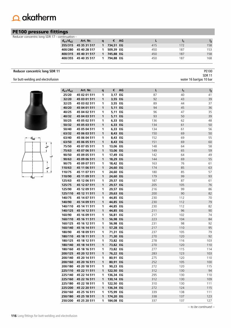
116
-- to be continued --
Reducer concentric long SDR 17 - continuation -PE100 pressure fittings
Long fittings for butt-welding and electrofusion
355/315 45 35 31 517 1 734,51 EG 415 172 158400/280 45 40 28 517 1 509,39 EG 450 187 153400/315 45 40 31 517 1 745,88 EG 450 187 158400/355 45 40 35 517 1 794,88 EG 450 187 168
de1/de2 Art. Nr. q € AG L l1 l2
Reducer concentric long SDR 11 PE100SDR 11
for butt-welding and electrofusion water 16 bar/gas 10 bar
de1/de2 Art. Nr. q € AG L l1 l225/20 45 02 01 511 1 3,17 EG 87 40 4132/20 45 03 01 511 1 3,55 EG 92 43 3932/25 45 03 02 511 1 3,55 EG 89 44 3740/20 45 04 01 511 1 5,11 EG 94 45 3640/25 45 04 02 511 1 5,11 EG 96 47 3540/32 45 04 03 511 1 5,11 EG 93 50 3950/25 45 05 02 511 1 6,33 EG 136 62 4850/32 45 05 03 511 1 6,33 EG 134 61 5050/40 45 05 04 511 1 6,33 EG 134 61 5663/32 45 06 03 511 1 8,43 EG 150 69 5063/40 45 06 04 511 1 8,43 EG 152 69 5563/50 45 06 05 511 1 8,43 EG 151 69 6075/50 45 07 05 511 1 13,06 EG 148 64 5875/63 45 07 06 511 1 13,06 EG 149 65 5990/50 45 09 05 511 1 17,49 EG 142 64 4990/63 45 09 06 511 1 18,29 EG 144 69 5590/75 45 09 07 511 1 18,42 EG 163 76 61
110/63 45 11 06 511 1 24,60 EG 174 85 63110/75 45 11 07 511 1 24,60 EG 180 85 57110/90 45 11 09 511 1 24,60 EG 179 99 93125/63 45 12 06 511 1 29,57 EG 187 87 61125/75 45 12 07 511 1 29,57 EG 205 105 76125/90 45 12 09 511 1 29,57 EG 216 99 86125/110 45 12 11 511 1 29,63 EG 200 90 82140/75 45 14 07 511 1 44,85 EG 230 112 70140/90 45 14 09 511 1 44,85 EG 230 112 79140/110 45 14 11 511 1 44,85 EG 230 112 82140/125 45 14 12 511 1 44,85 EG 211 96 90160/90 45 16 09 511 1 56,81 EG 217 102 74160/110 45 16 11 511 1 56,98 EG 223 104 84160/125 45 16 12 511 1 56,98 EG 231 98 92160/140 45 16 14 511 1 57,28 EG 217 110 95180/90 45 18 09 511 1 71,31 EG 237 105 79180/110 45 18 11 511 1 71,30 EG 270 120 92180/125 45 18 12 511 1 73,82 EG 278 116 103180/140 45 18 14 511 1 73,82 EG 270 120 110180/160 45 18 16 511 1 73,82 EG 277 115 114200/125 45 20 12 511 1 76,22 EG 283 123 103200/140 45 20 14 511 1 80,91 EG 275 120 110200/160 45 20 16 511 1 80,91 EG 252 105 100200/180 45 20 18 511 1 90,23 EG 272 120 115225/110 45 22 11 511 1 122,50 EG 312 130 94225/140 45 22 14 511 1 136,34 EG 295 130 110225/160 45 22 16 511 1 130,14 EG 312 130 109225/180 45 22 18 511 1 122,50 EG 310 130 111225/200 45 22 20 511 1 136,34 EG 272 124 115250/160 45 25 16 511 1 175,99 EG 339 138 111250/180 45 25 18 511 1 174,20 EG 338 137 123250/200 45 25 20 511 1 184,08 EG 337 137 127

117
Reducer concentric long SDR 11 - continuation -PE100 pressure fittings
Long fittings for butt-welding and electrofusion
250/225 45 25 22 511 1 184,08 EG 337 137 137280/180 45 28 18 511 1 218,79 EG 350 146 119280/200 45 28 20 511 1 218,79 EG 350 146 124280/225 45 28 22 511 1 218,79 EG 350 146 129280/250 45 28 25 511 1 245,32 EG 350 146 134315/200 45 31 20 511 1 315,63 EG 380 180 134315/225 45 31 22 511 1 315,63 EG 380 157 133315/250 45 31 25 511 1 315,63 EG 380 157 138315/280 45 31 28 511 1 315,63 EG 380 157 148355/250 45 35 25 511 1 480,49 EG 415 172 143355/280 45 35 28 511 1 722,23 EG 415 172 148355/315 45 35 31 511 1 741,65 EG 415 172 158400/280 45 40 28 511 1 672,54 EG 450 187 153400/315 45 40 31 511 1 734,51 EG 450 187 158400/355 45 40 35 511 1 794,88 EG 450 187 168
de1/de2 Art. Nr. q € AG L l1 l2

118
-- to be continued --
PE100 pressure fittings
Long fittings for butt-welding and electrofusion
End cap long SDR 17 PE100SDR 17
for butt-welding and electrofusion water 10 bar/gas 5 bar
de Art. Nr. q € AG L l
63 67 06 08 517 1 10,92 EF 85 6275 67 07 08 517 1 16,92 EF 95 6390 67 09 08 517 1 25,69 EF 110 79
110 67 11 08 517 1 34,84 EF 127 88125 67 12 08 517 1 37,64 EF 124 95140 67 14 08 517 1 47,08 EF 140 110160 67 16 08 517 1 52,75 EF 152 121180 67 18 08 517 1 68,59 EF 169 134200 67 20 08 517 1 85,44 EF 184 140225 67 22 08 517 1 101,99 EF 200 160250 67 25 08 517 1 137,49 EG 230 152280 67 28 08 517 1 195,28 EG 257 162315 67 31 08 517 1 261,15 EG 262 167355 67 35 08 517 1 405,26 EG 270 250400 67 40 08 517 1 711,34 EG 275 250450 67 45 08 517 1 531,58 EC *
* machined and extended with pipefabrication on order, returning not possible
285 250500 67 50 08 517 1 750,05 EC * 290 275560 67 56 08 517 1 1518,86 EC * 300 275630 67 63 08 517 1 1795,22 EC * 310 300710 67 71 08 517 1 4272,39 EC * 320 300800 67 80 08 517 1 4738,74 EC * 330 300
End cap long SDR 11 PE100SDR 11
for butt-welding and electrofusion water 16 bar/gas 10 bar
de Art. Nr. q € AG L l
20 67 01 08 511 1 3,69 EF 45 3525 67 02 08 511 1 4,05 EF 52 4032 67 03 08 511 1 5,11 EF 58 4440 67 04 08 511 1 6,33 EF 67 5050 67 05 08 511 1 8,28 EF 75 5563 67 06 08 511 1 10,92 EF 85 6275 67 07 08 511 1 16,92 EF 95 6390 67 09 08 511 1 25,69 EF 110 79
110 67 11 08 511 1 34,84 EF 127 88125 67 12 08 511 1 37,64 EF 124 95140 67 14 08 511 1 47,08 EF 140 110160 67 16 08 511 1 52,75 EF 152 121180 67 18 08 511 1 68,59 EF 169 134200 67 20 08 511 1 85,44 EF 184 140225 67 22 08 511 1 101,99 EF 200 160250 67 25 08 511 1 152,84 EG 230 152280 67 28 08 511 1 217,09 EG 257 162315 67 31 08 511 1 291,87 EG 262 167355 67 35 08 511 1 405,26 EG 280 250400 67 40 08 511 1 711,34 EG 285 250450 67 45 08 511 1 650,16 EC * 295 250500 67 50 08 511 1 842,49 EC * 305 275

119
End cap long SDR 11 - continuation -PE100 pressure fittings
Long fittings for butt-welding and electrofusion
560 67 56 08 511 1 1718,51 EC * 315 275630 67 63 08 511 1 2032,25 EC * 325 300710 67 71 08 511 1 o.r. EC * 320 300800 67 80 08 511 1 o.r. EC * 330 300
* machined and extended with pipefabrication on order, returning not possible
de Art. Nr. q € AG L l

120
PE100 pressure fittings
Long fittings for butt-welding and electrofusion
For PE pipes SDR 17-33.Exposed heating coil for direct heat transmission, extra long insertion depths, wide fusion and cold zone.
For PE pipes SDR 17-17,6. Other SDR values on request.Exposed heating coil for direct heat transmission, extra long insertion depths, wide fusion and cold zone.
Electrofusion coupler SDR 17-33 PE100AM, without center stop SDR 17for electrofusion water 10 bar
d Art. Nr. q € AG D L t kg
110 68 00 01 24 22,17 FF 128 160 80 0,60125 68 00 13 22 29,35 FF 146 160 80 0,62160 68 00 02 12 35,87 FF 184 180 90 1,10180 68 00 03 8 49,99 FF 206 180 90 1,70200 68 00 04 1 63,03 FF 229 180 90 3,20225 68 00 05 4 73,90 FF 250 200 100 2,00250 68 00 06 4 105,42 FF 280 200 100 2,65280 68 00 07 32 120,63 FF 315 200 100 3,45315 68 00 08 24 133,68 FF 355 220 110 4,90355 68 00 09 20 196,71 FF 400 220 110 6,10400 68 00 10 12 249,95 FF 450 220 110 7,85450 68 00 11 6 327,12 FF 500 220 110 8,40500 68 00 12 1 462,96 FF *
* separate fusion zones
560 270 135 14,90560 68 00 18 1 653,14 FF **
** separate fusion zones and pre-heating technique for compensation of a larger angular gap (d560-d630 compulsory)
630 380 190 24,20630 68 00 19 1 967,21 FF ** 710 420 210 36,80
Electrofusion coupler SDR 17 PE100UB, without center stop SDR 17for electrofusion water 10 bar/gas 5 bar
d Art. Nr. q € AG D L t kg
560 61 57 06 1 1119,35 FC *
* separate fusion zones and pre-heating technique for compensation of a larger annular gap (> 1 mm, max. 3 mm) (d500-d900 compulsory)d710-d900 compulsory use of hydraulic rounding clamp PWXRH
630 380 190 24,20630 61 57 26 1 1423,64 FC * 710 420 210 36,80710 61 59 94 1 1665,99 FC * 800 420 210 48,60800 61 62 90 1 3531,94 FC * 900 500 250 65,90900 61 63 45 1 o.r. * 1024 500 250 91,50
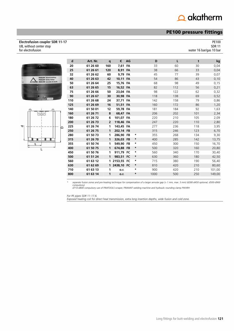
121
PE100 pressure fittings
Long fittings for butt-welding and electrofusion
For PE pipes SDR 11-17,6.Exposed heating coil for direct heat transmission, extra long insertion depths, wide fusion and cold zone.
Electrofusion coupler SDR 11-17 PE100UB, without center stop SDR 11for electrofusion water 16 bar/gas 10 bar
d Art. Nr. q € AG D L t kg
20 61 26 60 160 7,61 FA 33 60 30 0,0425 61 26 61 120 8,91 FA 38 66 33 0,0432 61 26 62 60 9,79 FA 45 77 39 0,0740 61 26 63 42 10,11 FA 54 86 43 0,1050 61 26 64 25 15,76 FA 68 98 49 0,1563 61 26 65 15 16,52 FA 82 112 56 0,2175 61 26 66 50 23,04 FA 98 122 62 0,3290 61 26 67 30 30,98 FA 118 138 69 0,52
110 61 26 68 24 37,71 FA 142 158 79 0,86125 61 26 69 16 51,51 FA 160 172 86 1,20140 61 50 01 12 59,78 FA 181 184 92 1,63160 61 26 71 8 68,47 FA 206 202 101 2,34180 61 26 72 6 101,07 FA 220 210 105 2,09200 61 26 73 2 118,46 FA 247 220 110 2,80225 61 26 74 1 143,45 FA 277 236 118 3,95250 61 26 75 1 202,14 FB 315 246 123 6,70280 61 50 73 1 286,90 FB *
* separate fusion zones and pre-heating technique for compensation of a larger annular gap (> 1 mm, max. 3 mm) (d280-d450 optional, d500-d900 compulsory)d710-d800 compulsory use of FRIATOOLS scraper, FRIAMAT welding machine and hydraulic rounding clamp PWXRH
355 268 134 9,30315 61 26 70 1 326,03 FB * 400 285 142 13,75355 61 50 74 1 549,90 FB * 450 300 150 16,70400 61 50 75 1 674,88 FB * 500 320 160 20,80450 61 50 76 1 911,79 FC * 560 340 170 30,40500 61 51 24 1 983,51 FC * 630 360 180 42,50560 61 63 12 1 2153,55 FC * 715 380 190 56,40630 61 62 69 1 2438,10 FC * 810 420 210 80,60710 61 63 13 1 o.r. * 900 420 210 101,00800 61 63 14 1 o.r. * 1000 500 250 149,00

122
PE100 pressure fittings
Long fittings for butt-welding and electrofusion
For PE pipes SDR 7,4-11.Exposed heating coil for direct heat transmission, extra long insertion depths, wide fusion and cold zone.
For PE pipes SDR 11-17,6.Exposed heating coil for direct heat transmission, extra long insertion depths, wide fusion and cold zone.Easily removable center stop.Also suitable as repair coupler.
Electrofusion coupler SDR 7,4-11 PE100UB, without center stop SDR 7,4for electrofusion water 25 bar
d Art. Nr. q € AG D L t kg
90 61 62 70 30 30,98 FA 117 138 69 0,53110 61 62 71 24 37,71 FA 142 159 79 0,89125 61 62 72 16 51,51 FA 160 172 86 1,20140 61 62 73 12 59,78 FA 181 184 92 1,62160 61 62 74 8 68,47 FA 206 203 95 2,36180 61 62 82 6 101,07 FA 225 210 105 2,95200 61 62 83 2 118,46 FA 250 224 110 3,87225 61 62 84 1 143,45 FA 280 240 118 5,16250 61 62 85 1 202,14 FB 315 246 123 6,84280 61 62 86 1 286,90 FB *
* separate fusion zones
355 268 134 10,70315 61 62 87 1 326,03 FB **
** separate fusion zones and pre-heating technique for compensation of a larger angular gap
400 285 142 13,40355 61 62 88 1 549,90 FB ** 450 300 150 17,90
Electrofusion coupler SDR 11-17 PE100MB, with center stop SDR 11for electrofusion water 16 bar/gas 10 bar
d Art. Nr. q € AG D L t kg
20 61 26 80 160 7,61 FA 33 60 29 0,0425 61 26 81 120 8,91 FA 38 66 32 0,0532 61 26 82 60 9,79 FA 45 78 38 0,0740 61 26 83 40 10,11 FA 54 85 42 0,1050 61 26 84 25 15,76 FA 68 98 48 0,1563 61 26 85 15 16,52 FA 82 110 55 0,2175 61 26 86 50 23,04 FA 98 122 60 0,3290 61 26 87 30 30,98 FA 117 138 68 0,52
110 61 26 88 24 37,71 FA 142 158 78 0,87125 61 26 89 16 51,51 FA 161 172 85 1,20140 61 26 90 12 59,78 FA 181 184 91 1,64160 61 26 91 8 68,47 FA 206 202 100 2,34

123
PE100 pressure fittings
Fittings made from pipe
Reduced pressure class, see appendix B2 "Maximum operating pressure for pipes and fittings".Fabrication on order, returning not possible.
Reduced pressure class, see appendix B2 "Maximum operating pressure for pipes and fittings".Fabrication on order, returning not possible.
Tee 90° welded SDR 33 PE100SDR 33
for butt-welding and electrofusion water 2 bar
de Art. Nr. q € AG L Z l1225 39 22 02 533 1 216,42 EL 530 265 150250 39 25 02 533 1 270,01 EL 750 375 250280 39 28 02 533 1 309,38 EL 780 390 250315 39 31 02 533 1 383,94 EL 920 460 300355 39 35 02 533 1 483,00 EL 960 480 300400 39 40 02 533 1 573,17 EL 1000 500 300450 39 45 02 533 1 798,34 EL 1050 525 300500 39 50 02 533 1 1137,70 EL 1200 600 350560 39 56 02 533 1 1629,71 EL 1260 630 350630 39 63 02 533 1 2000,18 EL 1330 665 350710 39 71 02 533 1 2663,14 EL 1410 705 350800 39 80 02 533 1 3160,74 EL 1500 750 350900 39 90 02 533 1 4189,85 EL 1700 850 4001000 39 91 02 533 1 4901,98 EL 1800 900 400
Tee 90° welded SDR 17 PE100SDR 17
for butt-welding and electrofusion water 6 bar
de Art. Nr. q € AG L Z l1225 39 22 02 517 1 240,43 EL 530 265 150250 39 25 02 517 1 299,97 EL 750 375 250280 39 28 02 517 1 343,79 EL 780 390 250315 39 31 02 517 1 426,60 EL 920 460 300355 39 35 02 517 1 536,59 EL 960 480 300400 39 40 02 517 1 636,92 EL 1000 500 300450 39 45 02 517 1 887,00 EL 1050 525 300500 39 50 02 517 1 1264,06 EL 1200 600 350560 39 56 02 517 1 1810,82 EL 1260 630 350630 39 63 02 517 1 2222,43 EL 1330 665 350710 39 71 02 517 1 2959,05 EL 1410 705 350800 39 80 02 517 1 3511,88 EL 1500 750 350

124
PE100 pressure fittings
Fittings made from pipe
Reduced pressure class, see appendix B2 "Maximum operating pressure for pipes and fittings".Fabrication on order, returning not possible.
Reduced pressure class, see appendix B2 "Maximum operating pressure for pipes and fittings".Fabrication on order, returning not possible.
Tee 90° welded SDR 11 PE100SDR 11
for butt-welding and electrofusion water 10 bar
de Art. Nr. q € AG L Z l1225 39 22 02 511 1 339,61 EL 530 265 150250 39 25 02 511 1 411,48 EL 750 375 250280 39 28 02 511 1 501,03 EL 780 390 250315 39 31 02 511 1 614,31 EL 920 460 300355 39 35 02 511 1 809,77 EL 960 480 300400 39 40 02 511 1 1012,74 EL 1000 500 300450 39 45 02 511 1 1235,49 EL 1050 525 300500 39 50 02 511 1 1686,09 EL 1200 600 350560 39 56 02 511 1 3371,42 EL 1260 630 350630 39 63 02 511 1 4088,73 EL 1330 665 350
Tee 60° welded SDR 33 PE100SDR 33
for butt-welding and electrofusion water 1,5 bar
de Art. Nr. q € AG L Z l1225 35 22 02 533 1 290,80 EL 760 445 250250 35 25 02 533 1 327,75 EL 889 517 300280 35 28 02 533 1 407,49 EL 923 543 300315 35 31 02 533 1 517,77 EL 1064 623 350355 35 35 02 533 1 931,38 EL 1110 658 350400 35 40 02 533 1 999,44 EL 1162 697 350450 35 45 02 533 1 1141,27 EL 1220 740 350500 35 50 02 533 1 1277,52 EL 1277 783 350560 35 56 02 533 1 1464,19 EL 1347 835 350630 35 63 02 533 1 1854,44 EL 1427 896 350710 35 71 02 533 1 o.r. EL 1520 965 350800 35 80 02 533 1 o.r. EL 1724 1093 400900 35 90 02 533 1 o.r. EL 1839 1180 4001000 35 91 02 533 1 o.r. EL 1955 1266 400

125
PE100 pressure fittings
Fittings made from pipe
Reduced pressure class, see appendix B2 "Maximum operating pressure for pipes and fittings".Fabrication on order, returning not possible.
Reduced pressure class, see appendix B2 "Maximum operating pressure for pipes and fittings".Fabrication on order, returning not possible.
Tee 60° welded SDR 17 PE100SDR 17
for butt-welding and electrofusion water 5 bar
de Art. Nr. q € AG L Z l1225 35 22 02 517 1 339,74 EL 760 445 250250 35 25 02 517 1 440,20 EL 889 517 300280 35 28 02 517 1 506,48 EL 923 543 300315 35 31 02 517 1 622,19 EL 1064 623 350355 35 35 02 517 1 778,16 EL 1110 658 350400 35 40 02 517 1 956,46 EL 1162 697 350450 35 45 02 517 1 1377,85 EL 1220 740 350500 35 50 02 517 1 1865,92 EL 1277 783 350560 35 56 02 517 1 2466,79 EL 1347 835 350630 35 63 02 517 1 3141,29 EL 1427 896 350710 35 71 02 517 1 4051,39 EL 1520 965 350800 35 80 02 517 1 o.r. EL 1724 1093 400
Tee 60° welded SDR 11 PE100SDR 11
for butt-welding and electrofusion water 8 bar
de Art. Nr. q € AG L Z l1225 35 22 02 511 1 508,53 EL 760 445 250250 35 25 02 511 1 660,42 EL 889 517 300280 35 28 02 511 1 759,74 EL 923 543 300315 35 31 02 511 1 933,22 EL 1064 623 350355 35 35 02 511 1 1167,04 EL 1110 658 350400 35 40 02 511 1 1435,65 EL 1162 697 350450 35 45 02 511 1 2065,83 EL 1220 740 350500 35 50 02 511 1 2682,44 EL 1277 783 350560 35 56 02 511 1 3445,08 EL 1347 835 350630 35 63 02 511 1 4416,91 EL 1427 896 350

126
PE100 pressure fittings
Fittings made from pipe
Reduced pressure class, see appendix B2 "Maximum operating pressure for pipes and fittings".Fabrication on order, returning not possible.
Reduced pressure class, see appendix B2 "Maximum operating pressure for pipes and fittings".Fabrication on order, returning not possible.
Tee 45° welded SDR 33 PE100SDR 33
for butt-welding and electrofusion water 1,5 bar
de Art. Nr. q € AG L Z l1225 30 22 02 533 1 265,23 EL 818 522 250250 30 25 02 533 1 296,78 EL 954 602 300280 30 28 02 533 1 374,64 EL 996 638 300315 30 31 02 533 1 467,23 EL 1145 730 350355 30 35 02 533 1 832,66 EL 1202 779 350400 30 40 02 533 1 900,56 EL 1266 833 350450 30 45 02 533 1 1036,70 EL 1336 893 350500 30 50 02 533 1 1140,10 EL 1407 954 350560 30 56 02 533 1 1320,31 EL 1492 1026 350630 30 63 02 533 1 1677,27 EL 1591 1110 350710 30 71 02 533 1 o.r. EL 1704 1207 350800 30 80 02 533 1 o.r. EL 1831 1316 350900 30 90 02 533 1 o.r. EL 2073 1486 4001000 30 91 02 533 1 o.r. EL 2214 1607 400
Tee 45° welded SDR 17 PE100SDR 17
for butt-welding and electrofusion water 4 bar
de Art. Nr. q € AG L Z l1225 30 22 02 517 1 381,27 EL 818 522 250250 30 25 02 517 1 514,11 EL 954 602 300280 30 28 02 517 1 593,36 EL 996 638 300315 30 31 02 517 1 730,65 EL 1145 730 350355 30 35 02 517 1 910,61 EL 1202 779 350400 30 40 02 517 1 1171,11 EL 1266 833 350450 30 45 02 517 1 1547,66 EL 1336 893 350500 30 50 02 517 1 2077,52 EL 1407 954 350560 30 56 02 517 1 2753,17 EL 1492 1026 350630 30 63 02 517 1 3495,75 EL 1591 1110 350710 30 71 02 517 1 4498,45 EL 1704 1207 350800 30 80 02 517 1 o.r. EL 1831 1316 350
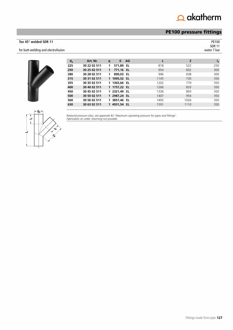
127
PE100 pressure fittings
Fittings made from pipe
Reduced pressure class, see appendix B2 "Maximum operating pressure for pipes and fittings".Fabrication on order, returning not possible.
Tee 45° welded SDR 11 PE100SDR 11
for butt-welding and electrofusion water 7 bar
de Art. Nr. q € AG L Z l1225 30 22 02 511 1 571,89 EL 818 522 250250 30 25 02 511 1 771,16 EL 954 602 300280 30 28 02 511 1 890,03 EL 996 638 300315 30 31 02 511 1 1095,52 EL 1145 730 350355 30 35 02 511 1 1365,66 EL 1202 779 350400 30 40 02 511 1 1757,22 EL 1266 833 350450 30 45 02 511 1 2321,49 EL 1336 893 350500 30 50 02 511 1 2987,24 EL 1407 954 350560 30 56 02 511 1 3857,46 EL 1492 1026 350630 30 63 02 511 1 4931,54 EL 1591 1110 350

128
-- to be continued --
PE100 pressure fittings
Fittings made from pipe
Tee 90° reduced welded SDR 17 PE100with reduced branch SDR 17for butt-welding and electrofusion water 6 bar
de1/de2 Art. Nr. q € AG L Z
110/32 29 11 03 517 1 37,97 EL 332 180110/40 29 11 04 517 1 43,07 EL 340 180110/50 29 11 05 517 1 49,78 EL 350 180110/63 29 11 06 517 1 57,28 EL 363 180110/75 29 11 07 517 1 67,57 EL 375 180125/32 29 12 03 517 1 41,29 EL 332 188125/40 29 12 04 517 1 47,24 EL 340 188125/50 29 12 05 517 1 53,47 EL 350 188125/63 29 12 06 517 1 60,32 EL 363 188125/75 29 12 07 517 1 71,00 EL 375 188125/90 29 12 09 517 1 85,22 EL 390 188140/32 29 14 03 517 1 43,82 EL 332 195140/40 29 14 04 517 1 51,57 EL 340 195140/50 29 14 05 517 1 57,15 EL 350 195140/63 29 14 06 517 1 63,89 EL 363 195140/75 29 14 07 517 1 74,17 EL 375 195140/90 29 14 09 517 1 91,07 EL 390 195140/110 29 14 11 517 1 105,91 EL 410 195160/32 29 16 03 517 1 46,61 EL 332 205160/40 29 16 04 517 1 55,50 EL 340 205160/50 29 16 05 517 1 61,22 EL 350 205160/63 29 16 06 517 1 66,55 EL 363 205160/75 29 16 07 517 1 76,71 EL 375 205160/90 29 16 09 517 1 93,48 EL 390 205160/110 29 16 11 517 1 107,57 EL 410 205160/125 29 16 12 517 1 120,14 EL 425 205180/32 29 18 03 517 1 54,36 EL 332 240180/40 29 18 04 517 1 61,47 EL 340 240180/50 29 18 05 517 1 71,00 EL 350 240180/63 29 18 06 517 1 73,41 EL 363 240180/75 29 18 07 517 1 83,31 EL 375 240180/90 29 18 09 517 1 99,32 EL 390 240180/110 29 18 11 517 1 113,55 EL 410 240180/125 29 18 12 517 1 126,75 EL 425 240180/140 29 18 14 517 1 143,39 EL 440 240200/32 29 20 03 517 1 58,67 EL 332 250200/40 29 20 04 517 1 63,64 EL 340 250200/50 29 20 05 517 1 70,60 EL 350 250200/63 29 20 06 517 1 77,73 EL 363 250200/75 29 20 07 517 1 87,77 EL 375 250200/90 29 20 09 517 1 104,54 EL 390 250200/110 29 20 11 517 1 118,37 EL 410 250200/125 29 20 12 517 1 128,66 EL 425 250200/140 29 20 14 517 1 143,26 EL 440 250200/160 29 20 16 517 1 154,19 EL 460 250225/63 29 22 06 517 1 86,00 EL 363 238225/75 29 22 07 517 1 96,39 EL 375 238225/90 29 22 09 517 1 111,89 EL 390 238225/110 29 22 11 517 1 125,61 EL 410 238225/125 29 22 12 517 1 138,17 EL 425 238225/140 29 22 14 517 1 154,43 EL 440 238225/160 29 22 16 517 1 163,84 EL 460 238225/180 29 22 18 517 1 173,62 EL 480 263250/75 29 25 07 517 1 100,72 EL 475 250250/90 29 25 09 517 1 117,24 EL 490 250250/110 29 25 11 517 1 130,96 EL 510 250

129
-- to be continued --
Tee 90° reduced welded SDR 17 - continuation -PE100 pressure fittings
Fittings made from pipe
250/125 29 25 12 517 1 143,51 EL 525 250250/140 29 25 14 517 1 160,91 EL 540 250250/160 29 25 16 517 1 170,82 EL 560 250250/180 29 25 18 517 1 180,22 EL 580 275250/200 29 25 20 517 1 192,16 EL 600 275280/75 29 28 07 517 1 111,26 EL 475 265280/90 29 28 09 517 1 128,42 EL 490 265280/110 29 28 11 517 1 143,39 EL 510 265280/125 29 28 12 517 1 154,43 EL 525 265280/140 29 28 14 517 1 171,59 EL 540 265280/160 29 28 16 517 1 181,10 EL 560 265280/180 29 28 18 517 1 190,75 EL 580 290280/200 29 28 20 517 1 201,18 EL 600 290280/225 29 28 22 517 1 212,24 EL 625 290315/90 29 31 09 517 1 139,84 EL 490 283315/110 29 31 11 517 1 153,67 EL 510 283315/125 29 31 12 517 1 167,38 EL 525 283315/140 29 31 14 517 1 184,30 EL 540 283315/160 29 31 16 517 1 198,77 EL 560 283315/180 29 31 18 517 1 211,08 EL 580 308315/200 29 31 20 517 1 222,13 EL 600 308315/225 29 31 22 517 1 236,87 EL 625 308315/250 29 31 25 517 1 256,68 EL 650 358355/110 29 35 11 517 1 181,10 EL 510 303355/125 29 35 12 517 1 192,16 EL 525 303355/140 29 35 14 517 1 209,56 EL 540 303355/160 29 35 16 517 1 224,54 EL 560 303355/180 29 35 18 517 1 236,62 EL 580 328355/200 29 35 20 517 1 251,73 EL 600 328355/225 29 35 22 517 1 267,60 EL 625 328355/250 29 35 25 517 1 288,94 EL 650 378355/280 29 35 28 517 1 292,75 EL 680 378400/110 29 40 11 517 1 195,08 EL 510 325400/125 29 40 12 517 1 207,91 EL 525 325400/140 29 40 14 517 1 224,54 EL 540 325400/160 29 40 16 517 1 237,63 EL 560 325400/180 29 40 18 517 1 258,07 EL 580 350400/200 29 40 20 517 1 277,52 EL 600 350400/225 29 40 22 517 1 301,90 EL 625 350400/250 29 40 25 517 1 330,97 EL 650 400400/280 29 40 28 517 1 362,34 EL 680 400400/315 29 40 31 517 1 389,78 EL 715 400450/110 29 45 11 517 1 231,27 EL 510 350450/125 29 45 12 517 1 246,00 EL 525 350450/140 29 45 14 517 1 262,90 EL 540 350450/160 29 45 16 517 1 283,22 EL 560 350450/180 29 45 18 517 1 303,16 EL 580 375450/200 29 45 20 517 1 326,29 EL 600 375450/225 29 45 22 517 1 354,72 EL 625 375450/250 29 45 25 517 1 383,55 EL 650 425450/280 29 45 28 517 1 419,62 EL 680 425450/315 29 45 31 517 1 466,10 EL 715 425450/355 29 45 35 517 1 544,58 EL 755 425500/110 29 50 11 517 1 343,54 EL 510 375500/125 29 50 12 517 1 367,93 EL 525 375500/140 29 50 14 517 1 388,25 EL 540 375500/160 29 50 16 517 1 414,42 EL 560 375500/180 29 50 18 517 1 437,27 EL 580 400500/200 29 50 20 517 1 469,28 EL 600 400500/225 29 50 22 517 1 510,80 EL 625 400
de1/de2 Art. Nr. q € AG L Z

130
Tee 90° reduced welded SDR 17 - continuation -PE100 pressure fittings
Fittings made from pipe
Reduced pressure class, see appendix B2 "Maximum operating pressure for pipes and fittings".Fabrication on order, returning not possible.
500/250 29 50 25 517 1 555,51 EL 650 450500/280 29 50 28 517 1 585,36 EL 680 450500/315 29 50 31 517 1 617,75 EL 715 450500/355 29 50 35 517 1 675,66 EL 755 450500/400 29 50 40 517 1 743,47 EL 800 450560/110 29 56 11 517 1 429,66 EL 510 480560/125 29 56 12 517 1 472,58 EL 525 480560/140 29 56 14 517 1 504,72 EL 540 480560/160 29 56 16 517 1 558,30 EL 560 480560/180 29 56 18 517 1 646,33 EL 580 480560/200 29 56 20 517 1 674,38 EL 600 480560/225 29 56 22 517 1 690,02 EL 625 480560/250 29 56 25 517 1 754,15 EL 650 480560/280 29 56 28 517 1 790,85 EL 680 480560/315 29 56 31 517 1 835,67 EL 715 480560/355 29 56 35 517 1 890,03 EL 755 480560/400 29 56 40 517 1 1010,17 EL 800 480630/160 29 63 16 517 1 635,90 EL 560 520630/180 29 63 18 517 1 732,05 EL 580 520630/200 29 63 20 517 1 766,98 EL 600 520630/225 29 63 22 517 1 780,95 EL 625 520630/250 29 63 25 517 1 853,85 EL 650 520630/280 29 63 28 517 1 895,50 EL 680 520630/315 29 63 31 517 1 944,40 EL 715 520630/355 29 63 35 517 1 1007,28 EL 755 520630/400 29 63 40 517 1 1141,38 EL 800 520630/455 29 63 45 517 1 1325,79 EL 850 520
de1/de2 Art. Nr. q € AG L Z

131
-- to be continued --
PE100 pressure fittings
Fittings made from pipe
Tee 90° reduced welded SDR 11 PE100with reduced branch SDR 11for butt-welding and electrofusion water 10 bar
de1/de2 Art. Nr. q € AG L Z
110/32 29 11 03 511 1 47,63 EL 332 180110/40 29 11 04 511 1 53,84 EL 340 180110/50 29 11 05 511 1 62,62 EL 350 180110/63 29 11 06 511 1 72,14 EL 363 180110/75 29 11 07 511 1 85,22 EL 375 180125/32 29 12 03 511 1 51,69 EL 332 188125/40 29 12 04 511 1 57,28 EL 340 188125/50 29 12 05 511 1 66,69 EL 350 188125/63 29 12 06 511 1 75,96 EL 363 188125/75 29 12 07 511 1 89,42 EL 375 188125/90 29 12 09 511 1 107,57 EL 390 188140/32 29 14 03 511 1 55,88 EL 332 195140/40 29 14 04 511 1 60,85 EL 340 195140/50 29 14 05 511 1 70,36 EL 350 195140/63 29 14 06 511 1 80,02 EL 363 195140/75 29 14 07 511 1 92,59 EL 375 195140/90 29 14 09 511 1 113,42 EL 390 195140/110 29 14 11 511 1 131,59 EL 410 195160/32 29 16 03 511 1 59,58 EL 332 205160/40 29 16 04 511 1 65,78 EL 340 205160/50 29 16 05 511 1 78,62 EL 350 205160/63 29 16 06 511 1 89,67 EL 363 205160/75 29 16 07 511 1 103,51 EL 375 205160/90 29 16 09 511 1 126,13 EL 390 205160/110 29 16 11 511 1 145,04 EL 410 205160/125 29 16 12 511 1 162,06 EL 425 205180/32 29 18 03 511 1 67,57 EL 332 240180/40 29 18 04 511 1 76,35 EL 340 240180/50 29 18 05 511 1 88,90 EL 350 240180/63 29 18 06 511 1 98,69 EL 363 240180/75 29 18 07 511 1 112,14 EL 375 240180/90 29 18 09 511 1 134,24 EL 390 240180/110 29 18 11 511 1 153,56 EL 410 240180/125 29 18 12 511 1 171,19 EL 425 240180/140 29 18 14 511 1 192,92 EL 440 240200/32 29 20 03 511 1 75,57 EL 332 250200/40 29 20 04 511 1 88,27 EL 340 250200/50 29 20 05 511 1 101,09 EL 350 250200/63 29 20 06 511 1 112,14 EL 363 250200/75 29 20 07 511 1 127,13 EL 375 250200/90 29 20 09 511 1 150,24 EL 390 250200/110 29 20 11 511 1 170,70 EL 410 250200/125 29 20 12 511 1 186,59 EL 425 250200/140 29 20 14 511 1 206,77 EL 440 250200/160 29 20 16 511 1 222,26 EL 460 250225/63 29 22 06 511 1 122,94 EL 363 238225/75 29 22 07 511 1 137,42 EL 375 238225/90 29 22 09 511 1 160,80 EL 390 238225/110 29 22 11 511 1 181,24 EL 410 238225/125 29 22 12 511 1 199,28 EL 425 238225/140 29 22 14 511 1 222,26 EL 440 238225/160 29 22 16 511 1 236,48 EL 460 238225/180 29 22 18 511 1 251,34 EL 480 263250/75 29 25 07 511 1 145,55 EL 475 250250/90 29 25 09 511 1 168,80 EL 490 250250/110 29 25 11 511 1 188,98 EL 510 250

132
-- to be continued --
Tee 90° reduced welded SDR 11 - continuation -PE100 pressure fittings
Fittings made from pipe
250/125 29 25 12 511 1 207,51 EL 525 250250/140 29 25 14 511 1 230,27 EL 540 250250/160 29 25 16 511 1 246,00 EL 560 250250/180 29 25 18 511 1 259,85 EL 580 275250/200 29 25 20 511 1 278,01 EL 600 275280/75 29 28 07 511 1 161,68 EL 475 265280/90 29 28 09 511 1 184,92 EL 490 265280/110 29 28 11 511 1 205,76 EL 510 265280/125 29 28 12 511 1 223,40 EL 525 265280/140 29 28 14 511 1 246,77 EL 540 265280/160 29 28 16 511 1 261,01 EL 560 265280/180 29 28 18 511 1 276,86 EL 580 290280/200 29 28 20 511 1 293,38 EL 600 290280/225 29 28 22 511 1 310,01 EL 625 290315/90 29 31 09 511 1 202,19 EL 490 283315/110 29 31 11 511 1 222,52 EL 510 283315/125 29 31 12 511 1 242,83 EL 525 283315/140 29 31 14 511 1 266,33 EL 540 283315/160 29 31 16 511 1 287,92 EL 560 283315/180 29 31 18 511 1 305,71 EL 580 308315/200 29 31 20 511 1 321,81 EL 600 308315/225 29 31 22 511 1 343,30 EL 625 308315/250 29 31 25 511 1 364,50 EL 650 358355/110 29 35 11 511 1 258,71 EL 510 303355/125 29 35 12 511 1 277,13 EL 525 303355/140 29 35 14 511 1 301,39 EL 540 303355/160 29 35 16 511 1 323,86 EL 560 303355/180 29 35 18 511 1 341,89 EL 580 328355/200 29 35 20 511 1 364,50 EL 600 328355/225 29 35 22 511 1 387,10 EL 625 328355/250 29 35 25 511 1 418,74 EL 650 378355/280 29 35 28 511 1 427,23 EL 680 378400/110 29 40 11 511 1 281,95 EL 510 325400/125 29 40 12 511 1 300,12 EL 525 325400/140 29 40 14 511 1 322,33 EL 540 325400/160 29 40 16 511 1 343,93 EL 560 325400/180 29 40 18 511 1 371,99 EL 580 350400/200 29 40 20 511 1 401,34 EL 600 350400/225 29 40 22 511 1 437,41 EL 625 350400/250 29 40 25 511 1 478,94 EL 650 400400/280 29 40 28 511 1 525,41 EL 680 400400/315 29 40 31 511 1 570,75 EL 715 400450/110 29 45 11 511 1 348,75 EL 510 350450/125 29 45 12 511 1 358,66 EL 525 350450/140 29 45 14 511 1 380,25 EL 540 350450/160 29 45 16 511 1 407,31 EL 560 350450/180 29 45 18 511 1 437,14 EL 580 375450/200 29 45 20 511 1 471,94 EL 600 375450/225 29 45 22 511 1 513,23 EL 625 375450/250 29 45 25 511 1 555,90 EL 650 425450/280 29 45 28 511 1 604,79 EL 680 425450/315 29 45 31 511 1 673,11 EL 715 425450/355 29 45 35 511 1 758,46 EL 755 425500/110 29 50 11 511 1 472,70 EL 510 375500/125 29 50 12 511 1 485,16 EL 525 375500/140 29 50 14 511 1 497,60 EL 540 375500/160 29 50 16 511 1 532,64 EL 560 375500/180 29 50 18 511 1 562,11 EL 580 400500/200 29 50 20 511 1 598,69 EL 600 400500/225 29 50 22 511 1 633,75 EL 625 400
de1/de2 Art. Nr. q € AG L Z

133
Tee 90° reduced welded SDR 11 - continuation -PE100 pressure fittings
Fittings made from pipe
Reduced pressure class, see appendix B2 "Maximum operating pressure for pipes and fittings".Fabrication on order, returning not possible.
500/250 29 50 25 511 1 677,82 EL 650 450500/280 29 50 28 511 1 732,30 EL 680 450500/315 29 50 31 511 1 806,98 EL 715 450500/355 29 50 35 511 1 872,26 EL 755 450500/400 29 50 40 511 1 955,32 EL 800 450560/110 29 56 11 511 1 549,80 EL 510 480560/125 29 56 12 511 1 580,91 EL 525 480560/140 29 56 14 511 1 612,03 EL 540 480560/160 29 56 16 511 1 653,56 EL 560 480560/180 29 56 18 511 1 798,72 EL 580 480560/200 29 56 20 511 1 856,91 EL 600 480560/225 29 56 22 511 1 893,60 EL 625 480560/250 29 56 25 511 1 920,90 EL 650 480560/280 29 56 28 511 1 981,87 EL 680 480560/315 29 56 31 511 1 1032,68 EL 715 480560/355 29 56 35 511 1 1095,16 EL 755 480560/400 29 56 40 511 1 1198,03 EL 800 480630/160 29 63 16 511 1 750,20 EL 560 520630/180 29 63 18 511 1 912,26 EL 580 520630/200 29 63 20 511 1 978,43 EL 600 520630/225 29 63 22 511 1 1020,85 EL 625 520630/250 29 63 25 511 1 920,90 EL 650 520630/280 29 63 28 511 1 1120,30 EL 680 520630/315 29 63 31 511 1 1177,96 EL 715 520630/355 29 63 35 511 1 1248,94 EL 755 520630/400 29 63 40 511 1 1365,17 EL 800 520630/455 29 63 45 511 1 1563,29 EL 850 520
de1/de2 Art. Nr. q € AG L Z

134
-- to be continued --
PE100 pressure fittings
Fittings made from pipe
Tee 60° reduced extrusion welded SDR 17 PE100with reduced branch SDR 17for butt-welding and electrofusion non pressure, gravity
de1/de2 Art. Nr. q € AG L Z
125/110 35 12 11 517 1 118,74 EL 527 304140/110 35 14 11 517 1 139,45 EL 527 313160/110 35 16 11 517 1 112,52 EL 527 324160/125 35 16 12 517 1 128,02 EL 544 329180/110 35 18 11 517 1 136,03 EL 527 336180/125 35 18 12 517 1 145,30 EL 544 340180/140 35 18 14 517 1 159,52 EL 562 344200/110 35 20 11 517 1 155,45 EL 627 397200/125 35 20 12 517 1 167,91 EL 644 402200/140 35 20 14 517 1 181,10 EL 662 406200/160 35 20 16 517 1 191,27 EL 685 412225/110 35 22 11 517 1 163,84 EL 627 412225/125 35 22 12 517 1 170,82 EL 644 416225/140 35 22 14 517 1 181,10 EL 662 420225/160 35 22 16 517 1 189,37 EL 685 426225/180 35 22 18 517 1 213,87 EL 708 432250/110 35 25 11 517 1 201,18 EL 727 476250/125 35 25 12 517 1 207,91 EL 744 480250/140 35 25 14 517 1 218,95 EL 762 485250/160 35 25 16 517 1 259,33 EL 785 491250/180 35 25 18 517 1 284,11 EL 808 496250/200 35 25 20 517 1 298,71 EL 831 502280/110 35 28 11 517 1 223,27 EL 727 493280/125 35 28 12 517 1 238,65 EL 744 498280/140 35 28 14 517 1 248,16 EL 762 502280/160 35 28 16 517 1 273,82 EL 785 508280/180 35 28 18 517 1 310,01 EL 808 514280/200 35 28 20 517 1 361,70 EL 831 519280/225 35 28 22 517 1 392,70 EL 860 527315/110 35 31 11 517 1 320,44 EL 827 564315/125 35 31 12 517 1 332,76 EL 844 568315/140 35 31 14 517 1 349,39 EL 862 572315/160 35 31 16 517 1 368,95 EL 885 578315/180 35 31 18 517 1 392,70 EL 908 584315/200 35 31 20 517 1 417,59 EL 931 590315/225 35 31 22 517 1 441,21 EL 960 597315/250 35 31 25 517 1 465,09 EL 989 604355/110 35 35 11 517 1 375,31 EL 827 587355/125 35 35 12 517 1 386,47 EL 844 591355/140 35 35 14 517 1 399,93 EL 862 595355/160 35 35 16 517 1 417,59 EL 885 601355/180 35 35 18 517 1 436,01 EL 908 607355/200 35 35 20 517 1 461,92 EL 931 613355/225 35 35 22 517 1 480,59 EL 960 620355/250 35 35 25 517 1 496,84 EL 989 627355/280 35 35 28 517 1 578,51 EL 1023 636400/110 35 40 11 517 1 474,11 EL 827 613400/125 35 40 12 517 1 487,44 EL 844 617400/140 35 40 14 517 1 513,73 EL 862 621400/160 35 40 16 517 1 529,85 EL 885 627400/180 35 40 18 517 1 543,07 EL 908 633400/200 35 40 20 517 1 579,52 EL 931 639400/225 35 40 22 517 1 616,10 EL 960 646400/250 35 40 25 517 1 634,25 EL 989 653400/280 35 40 28 517 1 662,58 EL 1023 662400/315 35 40 31 517 1 679,85 EL 1064 672

135
Tee 60° reduced extrusion welded SDR 17 - continuation -PE100 pressure fittings
Fittings made from pipe
For non pressure applications.Fabrication on order, returning not possible.
450/110 35 45 11 517 1 558,30 EL 827 642450/125 35 45 12 517 1 569,48 EL 844 646450/140 35 45 14 517 1 578,51 EL 862 650450/160 35 45 16 517 1 594,75 EL 702 656450/180 35 45 18 517 1 614,95 EL 908 662450/200 35 45 20 517 1 664,61 EL 931 668450/225 35 45 22 517 1 692,93 EL 960 675450/250 35 45 25 517 1 789,20 EL 989 682450/280 35 45 28 517 1 859,18 EL 1023 691450/315 35 45 31 517 1 1004,99 EL 1064 701
de1/de2 Art. Nr. q € AG L Z

136
-- to be continued --
PE100 pressure fittings
Fittings made from pipe
Tee 60° reduced extrusion welded SDR 11 PE100with reduced branch SDR 11for butt-welding and electrofusion non pressure, gravity
de1/de2 Art. Nr. q € AG L Z
125/110 35 12 11 511 1 178,45 EL 527 304140/110 35 14 11 511 1 209,44 EL 527 313160/110 35 16 11 511 1 168,80 EL 527 324160/125 35 16 12 511 1 192,41 EL 544 329180/110 35 18 11 511 1 204,87 EL 527 336180/125 35 18 12 511 1 218,07 EL 544 340180/140 35 18 14 511 1 240,54 EL 562 344200/110 35 20 11 511 1 233,30 EL 627 397200/125 35 20 12 511 1 251,59 EL 644 402200/140 35 20 14 511 1 272,18 EL 662 406200/160 35 20 16 511 1 287,53 EL 685 412225/110 35 22 11 511 1 245,75 EL 627 412225/125 35 22 12 511 1 256,80 EL 644 416225/140 35 22 14 511 1 271,15 EL 662 420225/160 35 22 16 511 1 283,47 EL 685 426225/180 35 22 18 511 1 321,32 EL 708 432250/110 35 25 11 511 1 301,25 EL 727 476250/125 35 25 12 511 1 311,16 EL 744 480250/140 35 25 14 511 1 327,41 EL 762 485250/160 35 25 16 511 1 388,50 EL 785 491250/180 35 25 18 511 1 425,84 EL 808 496250/200 35 25 20 511 1 447,55 EL 831 502280/110 35 28 11 511 1 334,92 EL 727 493280/125 35 28 12 511 1 357,51 EL 744 498280/140 35 28 14 511 1 371,10 EL 762 502280/160 35 28 16 511 1 411,23 EL 785 508280/180 35 28 18 511 1 463,94 EL 808 514280/200 35 28 20 511 1 542,55 EL 831 519280/225 35 28 22 511 1 588,03 EL 860 527315/110 35 31 11 511 1 480,59 EL 827 564315/125 35 31 12 511 1 499,26 EL 844 568315/140 35 31 14 511 1 522,75 EL 862 572315/160 35 31 16 511 1 552,84 EL 885 578315/180 35 31 18 511 1 590,06 EL 908 584315/200 35 31 20 511 1 626,26 EL 931 590315/225 35 31 22 511 1 662,45 EL 960 597315/250 35 31 25 511 1 697,49 EL 989 604355/110 35 35 11 511 1 562,11 EL 827 587355/125 35 35 12 511 1 579,77 EL 844 591355/140 35 35 14 511 1 600,36 EL 862 595355/160 35 35 16 511 1 625,25 EL 885 601355/180 35 35 18 511 1 654,20 EL 908 607355/200 35 35 20 511 1 693,32 EL 931 613355/225 35 35 22 511 1 720,25 EL 960 620355/250 35 35 25 511 1 745,40 EL 989 627355/280 35 35 28 511 1 867,30 EL 1023 636400/110 35 40 11 511 1 710,20 EL 827 613400/125 35 40 12 511 1 730,53 EL 844 617400/140 35 40 14 511 1 769,90 EL 862 621400/160 35 40 16 511 1 795,29 EL 885 627400/180 35 40 18 511 1 813,58 EL 908 633400/200 35 40 20 511 1 869,34 EL 931 639400/225 35 40 22 511 1 923,07 EL 960 646400/250 35 40 25 511 1 951,26 EL 989 653400/280 35 40 28 511 1 992,91 EL 1023 662400/315 35 40 31 511 1 1020,09 EL 1064 672

137
Tee 60° reduced extrusion welded SDR 11 - continuation -PE100 pressure fittings
Fittings made from pipe
For non pressure applications.Fabrication on order, returning not possible.
450/110 35 45 11 511 1 837,84 EL 827 642450/125 35 45 12 511 1 854,36 EL 844 646450/140 35 45 14 511 1 867,30 EL 862 650450/160 35 45 16 511 1 891,57 EL 702 656450/180 35 45 18 511 1 921,92 EL 908 662450/200 35 45 20 511 1 997,10 EL 931 668450/225 35 45 22 511 1 1040,54 EL 960 675450/250 35 45 25 511 1 1184,31 EL 989 682450/280 35 45 28 511 1 1287,69 EL 1023 691450/315 35 45 31 511 1 1508,68 EL 1064 701
de1/de2 Art. Nr. q € AG L Z

138
-- to be continued --
PE100 pressure fittings
Fittings made from pipe
Tee 45° reduced extrusion welded SDR 17 PE100with reduced branch SDR 17for butt-welding and electrofusion non pressure, gravity
de1/de2 Art. Nr. q € AG L Z
125/110 30 12 11 517 1 154,43 EL 556 343140/110 30 14 11 517 1 180,99 EL 556 354160/110 30 16 11 517 1 129,42 EL 556 368160/125 30 16 12 517 1 143,77 EL 577 376180/110 30 18 11 517 1 136,28 EL 556 382180/125 30 18 12 517 1 151,39 EL 577 390180/140 30 18 14 517 1 164,48 EL 598 397200/110 30 20 11 517 1 156,36 EL 655 446200/125 30 20 12 517 1 171,45 EL 677 454200/140 30 20 14 517 1 192,41 EL 698 461200/160 30 20 16 517 1 216,93 EL 726 471225/110 30 22 11 517 1 171,34 EL 656 464225/125 30 22 12 517 1 186,84 EL 677 472225/140 30 22 14 517 1 195,58 EL 698 479225/160 30 22 16 517 1 221,12 EL 726 489225/180 30 22 18 517 1 237,50 EL 755 499250/110 30 25 11 517 1 205,76 EL 756 532250/125 30 25 12 517 1 209,30 EL 777 539250/140 30 25 14 517 1 230,77 EL 798 547250/160 30 25 16 517 1 268,99 EL 826 557250/180 30 25 18 517 1 294,65 EL 855 567250/200 30 25 20 517 1 314,85 EL 883 577280/110 30 28 11 517 1 228,61 EL 756 553280/125 30 28 12 517 1 243,98 EL 777 560280/140 30 28 14 517 1 252,47 EL 798 568280/160 30 28 16 517 1 305,45 EL 826 578280/180 30 28 18 517 1 318,02 EL 855 588280/200 30 28 20 517 1 371,61 EL 883 598280/225 30 28 22 517 1 406,80 EL 918 610315/110 30 31 11 517 1 324,50 EL 856 628315/125 30 31 12 517 1 340,25 EL 877 635315/140 30 31 14 517 1 360,69 EL 898 643315/160 30 31 16 517 1 383,94 EL 926 653315/180 30 31 18 517 1 417,59 EL 955 663315/200 30 31 20 517 1 440,32 EL 983 673315/225 30 31 22 517 1 482,10 EL 1018 685315/250 30 31 25 517 1 500,01 EL 1054 698355/110 30 35 11 517 1 382,79 EL 856 656355/125 30 35 12 517 1 399,42 EL 877 664355/140 30 35 14 517 1 408,06 EL 898 671355/160 30 35 16 517 1 431,56 EL 926 681355/180 30 35 18 517 1 451,12 EL 955 691355/200 30 35 20 517 1 483,63 EL 983 701355/225 30 35 22 517 1 493,28 EL 1018 714355/250 30 35 25 517 1 536,21 EL 1054 726355/280 30 35 28 517 1 618,40 EL 1096 741400/110 30 40 11 517 1 489,72 EL 856 688400/125 30 40 12 517 1 505,10 EL 877 695400/140 30 40 14 517 1 529,10 EL 898 703400/160 30 40 16 517 1 549,16 EL 926 713400/180 30 40 18 517 1 579,39 EL 955 723400/200 30 40 20 517 1 603,53 EL 983 733400/225 30 40 22 517 1 638,82 EL 1018 745400/250 30 40 25 517 1 661,82 EL 1054 758400/280 30 40 28 517 1 687,35 EL 1096 773400/315 30 40 31 517 1 717,57 EL 1145 790
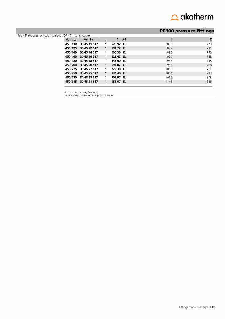
139
Tee 45° reduced extrusion welded SDR 17 - continuation -PE100 pressure fittings
Fittings made from pipe
For non pressure applications.Fabrication on order, returning not possible.
450/110 30 45 11 517 1 575,97 EL 856 723450/125 30 45 12 517 1 591,72 EL 877 731450/140 30 45 14 517 1 600,36 EL 898 738450/160 30 45 16 517 1 623,47 EL 926 748450/180 30 45 18 517 1 643,90 EL 955 758450/200 30 45 20 517 1 694,07 EL 983 768450/225 30 45 22 517 1 729,38 EL 1018 781450/250 30 45 25 517 1 834,40 EL 1054 793450/280 30 45 28 517 1 901,97 EL 1096 808450/315 30 45 31 517 1 955,07 EL 1145 826
de1/de2 Art. Nr. q € AG L Z

140
-- to be continued --
PE100 pressure fittings
Fittings made from pipe
Tee 45° reduced extrusion welded SDR 11 PE100with reduced branch SDR 11for butt-welding and electrofusion non pressure, gravity
de1/de2 Art. Nr. q € AG L Z
125/110 30 12 11 511 1 231,90 EL 556 343140/110 30 14 11 511 1 271,29 EL 556 354160/110 30 16 11 511 1 193,95 EL 556 368160/125 30 16 12 511 1 215,66 EL 577 376180/110 30 18 11 511 1 204,23 EL 556 382180/125 30 18 12 511 1 227,34 EL 577 390180/140 30 18 14 511 1 246,39 EL 598 397200/110 30 20 11 511 1 234,59 EL 655 446200/125 30 20 12 511 1 256,95 EL 677 454200/140 30 20 14 511 1 288,81 EL 698 461200/160 30 20 16 511 1 325,64 EL 726 471225/110 30 22 11 511 1 256,95 EL 656 464225/125 30 22 12 511 1 280,30 EL 677 472225/140 30 22 14 511 1 293,51 EL 698 479225/160 30 22 16 511 1 331,61 EL 726 489225/180 30 22 18 511 1 356,24 EL 755 499250/110 30 25 11 511 1 308,75 EL 756 532250/125 30 25 12 511 1 313,95 EL 777 539250/140 30 25 14 511 1 346,10 EL 798 547250/160 30 25 16 511 1 403,24 EL 826 557250/180 30 25 18 511 1 442,23 EL 855 567250/200 30 25 20 511 1 472,46 EL 883 577280/110 30 28 11 511 1 342,78 EL 756 553280/125 30 28 12 511 1 365,77 EL 777 560280/140 30 28 14 511 1 378,60 EL 798 568280/160 30 28 16 511 1 457,98 EL 826 578280/180 30 28 18 511 1 476,91 EL 855 588280/200 30 28 20 511 1 557,29 EL 883 598280/225 30 28 22 511 1 610,39 EL 918 610315/110 30 31 11 511 1 486,68 EL 856 628315/125 30 31 12 511 1 510,29 EL 877 635315/140 30 31 14 511 1 540,91 EL 898 643315/160 30 31 16 511 1 575,83 EL 926 653315/180 30 31 18 511 1 626,63 EL 955 663315/200 30 31 20 511 1 660,29 EL 983 673315/225 30 31 22 511 1 723,28 EL 1018 685315/250 30 31 25 511 1 750,20 EL 1054 698355/110 30 35 11 511 1 574,18 EL 856 656355/125 30 35 12 511 1 599,33 EL 877 664355/140 30 35 14 511 1 612,03 EL 898 671355/160 30 35 16 511 1 647,35 EL 926 681355/180 30 35 18 511 1 676,56 EL 955 691355/200 30 35 20 511 1 725,57 EL 983 701355/225 30 35 22 511 1 739,91 EL 1018 714355/250 30 35 25 511 1 804,18 EL 1054 726355/280 30 35 28 511 1 927,38 EL 1096 741400/110 30 40 11 511 1 734,59 EL 856 688400/125 30 40 12 511 1 757,44 EL 877 695400/140 30 40 14 511 1 794,42 EL 898 703400/160 30 40 16 511 1 823,63 EL 926 713400/180 30 40 18 511 1 869,09 EL 955 723400/200 30 40 20 511 1 905,03 EL 983 733400/225 30 40 22 511 1 958,11 EL 1018 745400/250 30 40 25 511 1 989,86 EL 1054 758400/280 30 40 28 511 1 1030,76 EL 1096 773400/315 30 40 31 511 1 1076,23 EL 1145 790

141
Tee 45° reduced extrusion welded SDR 11 - continuation -PE100 pressure fittings
Fittings made from pipe
For non pressure applications.Fabrication on order, returning not possible.
450/110 30 45 11 511 1 863,76 EL 856 723450/125 30 45 12 511 1 887,38 EL 877 731450/140 30 45 14 511 1 900,84 EL 898 738450/160 30 45 16 511 1 935,63 EL 926 748450/180 30 45 18 511 1 965,22 EL 955 758450/200 30 45 20 511 1 1041,05 EL 983 768450/225 30 45 22 511 1 1114,71 EL 1018 781450/250 30 45 25 511 1 1251,87 EL 1054 793450/280 30 45 28 511 1 1352,59 EL 1096 808450/315 30 45 31 511 1 1432,08 EL 1145 826
de1/de2 Art. Nr. q € AG L Z

142
-- to be continued --
PE100 pressure fittings
Fittings made from pipe
Tee 90° reduced machined long SDR17 - pressure class conform PE100with reduced branch SDR 17for butt-welding and electrofusion water 10 bar/gas 5 bar
de1/de2 Art. Nr. q € AG L Z
280/63 41 28 06 517 1 915,02 EC 770 365280/75 41 28 07 517 1 931,29 EC 780 365280/90 41 28 09 517 1 958,31 EC 795 365280/110 41 28 11 517 1 992,45 EC 815 365280/125 41 28 12 517 1 1030,46 EC 830 365280/140 41 28 14 517 1 1066,31 EC 845 365280/160 41 28 16 517 1 1188,15 EC 865 365280/180 41 28 18 517 1 1272,86 EC 885 365280/200 41 28 20 517 1 1356,69 EC 905 365280/225 41 28 22 517 1 1613,35 EC 930 365315/75 41 31 07 517 1 1032,18 EC 780 380315/90 41 31 09 517 1 1054,74 EC 795 380315/110 41 31 11 517 1 1257,64 EC 815 380315/125 41 31 12 517 1 1300,92 EC 830 380315/140 41 31 14 517 1 1234,05 EC 845 380315/160 41 31 16 517 1 1407,11 EC 865 380315/180 41 31 18 517 1 1471,10 EC 885 380315/200 41 31 20 517 1 1527,90 EC 905 380315/225 41 31 22 517 1 1897,21 EC 930 380315/250 41 31 25 517 1 2023,32 EC 955 380355/90 41 35 09 517 1 1232,54 EC 805 400355/110 41 35 11 517 1 1314,43 EC 825 400355/125 41 35 12 517 1 1351,41 EC 840 400355/140 41 35 14 517 1 1410,45 EC 855 400355/160 41 35 16 517 1 1648,00 EC 875 400355/180 41 35 18 517 1 1721,04 EC 895 400355/200 41 35 20 517 1 1802,13 EC 915 400355/225 41 35 22 517 1 1896,81 EC 940 400355/250 41 35 25 517 1 2014,77 EC 965 400355/280 41 35 28 517 1 2459,19 EC 1000 400400/110 41 40 11 517 1 1549,64 EC 825 425400/125 41 40 12 517 1 1601,17 EC 840 425400/140 41 40 14 517 1 1650,74 EC 855 425400/160 41 40 16 517 1 1697,57 EC 875 425400/180 41 40 18 517 1 2006,66 EC 895 425400/200 41 40 20 517 1 2094,12 EC 915 425400/225 41 40 22 517 1 2187,71 EC 940 425400/250 41 40 25 517 1 2323,86 EC 965 425400/280 41 40 28 517 1 2779,02 EC 1000 425400/315 41 40 31 517 1 3007,01 EC 1035 425450/125 41 45 12 517 1 1753,76 EC 840 450450/140 41 45 14 517 1 1805,38 EC 855 450450/160 41 45 16 517 1 1875,58 EC 875 450450/180 41 45 18 517 1 2141,37 EC 895 450450/200 41 45 20 517 1 2226,11 EC 915 450450/225 41 45 22 517 1 2307,20 EC 940 450450/250 41 45 25 517 1 2685,76 EC 965 450450/280 41 45 28 517 1 2850,56 EC 1000 450450/315 41 45 31 517 1 3072,35 EC 1035 450450/355 41 45 35 517 1 3894,11 EC 1075 450500/140 41 50 14 517 1 2287,88 EC 855 475500/160 41 50 16 517 1 2349,34 EC 875 475500/180 41 50 18 517 1 2435,71 EC 895 475500/200 41 50 20 517 1 2524,01 EC 915 475500/225 41 50 22 517 1 3308,98 EC 940 475500/250 41 50 25 517 1 3497,25 EC 965 475

143
Tee 90° reduced machined long SDR17 - pressure class conform - continuation -PE100 pressure fittings
Fittings made from pipe
Pressure class guaranteed, all branches extended with pipe.Fabrication on order, returning not possible.
500/280 41 50 28 517 1 3521,84 EC 1000 475500/315 41 50 31 517 1 3949,50 EC 1035 475500/355 41 50 35 517 1 4234,19 EC 1075 475500/400 41 50 40 517 1 4720,95 EC 1120 475560/160 41 56 16 517 1 3025,22 EC 875 500560/180 41 56 18 517 1 3140,53 EC 895 500560/200 41 56 20 517 1 3225,08 EC 915 500560/225 41 56 22 517 1 3413,74 EC 940 500560/250 41 56 25 517 1 3491,05 EC 965 500560/280 41 56 28 517 1 3713,57 EC 1000 500560/315 41 56 31 517 1 4101,69 EC 1035 500560/355 41 56 35 517 1 4806,61 EC 1075 500560/400 41 56 40 517 1 5305,99 EC 1120 500560/450 41 56 45 517 1 6495,34 EC 1170 500560/560 41 56 56 517 1 9486,93 EC 1280 500630/180 41 63 18 517 1 3649,45 EC 895 540630/200 41 63 20 517 1 3742,33 EC 915 540630/225 41 63 22 517 1 3891,78 EC 940 540630/250 41 63 25 517 1 4094,49 EC 965 540630/280 41 63 28 517 1 4298,99 EC 1000 540630/315 41 63 31 517 1 5241,87 EC 1035 540630/355 41 63 35 517 1 5567,10 EC 1075 540630/400 41 63 40 517 1 6124,90 EC 1120 540630/450 41 63 45 517 1 7092,67 EC 1170 540630/500 41 63 50 517 1 8733,65 EC 1220 540630/630 41 63 63 517 1 14488,20 EC 1350 540710/180 41 71 18 517 1 5204,49 EC 895 620710/200 41 71 20 517 1 5320,62 EC 915 620710/225 41 71 22 517 1 5433,49 EC 940 620710/250 41 71 25 517 1 5648,59 EC 965 620710/280 41 71 28 517 1 5831,47 EC 1000 620710/315 41 71 31 517 1 6315,40 EC 1035 620710/355 41 71 35 517 1 6639,11 EC 1075 620710/400 41 71 40 517 1 7091,94 EC 1120 620710/450 41 71 45 517 1 7940,53 EC 1170 620710/500 41 71 50 517 1 8993,43 EC 1220 620710/560 41 71 56 517 1 10167,86 EC 1280 620710/710 41 71 71 517 1 17059,55 EC 1450 650
de1/de2 Art. Nr. q € AG L Z

144
-- to be continued --
PE100 pressure fittings
Fittings made from pipe
Tee 90° reduced machined long SDR11 - pressure class conform PE100with reduced branch SDR 11for butt-welding and electrofusion water 16 bar/gas 10 bar
de1/de2 Art. Nr. q € AG L Z
280/63 41 28 06 511 1 1006,58 EC 770 365280/75 41 28 07 511 1 1023,45 EC 780 365280/90 41 28 09 511 1 1051,48 EC 795 365280/110 41 28 11 511 1 1087,04 EC 815 365280/125 41 28 12 511 1 1126,56 EC 830 365280/140 41 28 14 511 1 1163,76 EC 845 365280/160 41 28 16 511 1 1290,36 EC 865 365280/180 41 28 18 511 1 1347,97 EC 885 365280/200 41 28 20 511 1 1465,53 EC 905 365280/225 41 28 22 511 1 1732,32 EC 930 365315/75 41 31 07 511 1 1116,91 EC 780 380315/90 41 31 09 511 1 1140,39 EC 795 380315/110 41 31 11 511 1 1351,22 EC 815 380315/125 41 31 12 511 1 1396,10 EC 830 380315/140 41 31 14 511 1 1442,96 EC 845 380315/160 41 31 16 511 1 1506,55 EC 865 380315/180 41 31 18 511 1 1573,10 EC 885 380315/200 41 31 20 511 1 1632,04 EC 905 380315/225 41 31 22 511 1 2016,00 EC 930 380315/250 41 31 25 511 1 2146,97 EC 955 380355/90 41 35 09 511 1 1342,58 EC 805 400355/110 41 35 11 511 1 1427,62 EC 825 400355/125 41 35 12 511 1 1466,13 EC 840 400355/140 41 35 14 511 1 1527,39 EC 855 400355/160 41 35 16 511 1 1774,28 EC 875 400355/180 41 35 18 511 1 1850,08 EC 895 400355/200 41 35 20 511 1 1934,42 EC 915 400355/225 41 35 22 511 1 2032,77 EC 940 400355/250 41 35 25 511 1 2155,08 EC 965 400355/280 41 35 28 511 1 2617,19 EC 1000 400400/110 41 40 11 511 1 1704,79 EC 825 425400/125 41 40 12 511 1 1758,13 EC 840 425400/140 41 40 14 511 1 1809,84 EC 855 425400/160 41 40 16 511 1 1858,41 EC 875 425400/180 41 40 18 511 1 2179,67 EC 895 425400/200 41 40 20 511 1 2270,51 EC 915 425400/225 41 40 22 511 1 2367,75 EC 940 425400/250 41 40 25 511 1 2509,17 EC 965 425400/280 41 40 28 511 1 2982,34 EC 1000 425400/315 41 40 31 511 1 3219,27 EC 1035 425450/125 41 45 12 511 1 1918,47 EC 840 450450/140 41 45 14 511 1 1972,10 EC 855 450450/160 41 45 16 511 1 2044,96 EC 875 450450/180 41 45 18 511 1 2321,20 EC 895 450450/200 41 45 20 511 1 2409,29 EC 915 450450/225 41 45 22 511 1 2493,42 EC 940 450450/250 41 45 25 511 1 2886,94 EC 965 450450/280 41 45 28 511 1 3058,34 EC 1000 450450/315 41 45 31 511 1 3288,65 EC 1035 450450/355 41 45 35 511 1 4142,64 EC 1075 450500/140 41 50 14 511 1 2493,11 EC 855 475500/160 41 50 16 511 1 2557,02 EC 875 475500/180 41 50 18 511 1 2646,84 EC 895 475500/200 41 50 20 511 1 2738,60 EC 915 475500/225 41 50 22 511 1 3554,47 EC 940 475500/250 41 50 25 511 1 3750,04 EC 965 475

145
Tee 90° reduced machined long SDR11 - pressure class conform - continuation -PE100 pressure fittings
Fittings made from pipe
Pressure class guaranteed, all branches extended with pipe.Fabrication on order, returning not possible.
500/280 41 50 28 511 1 3775,56 EC 1000 475500/315 41 50 31 511 1 4219,96 EC 1035 475500/355 41 50 35 511 1 4515,82 EC 1075 475500/400 41 50 40 511 1 5021,61 EC 1120 475560/160 41 56 16 511 1 3307,26 EC 875 500560/180 41 56 18 511 1 3427,14 EC 895 500560/200 41 56 20 511 1 3514,94 EC 915 500560/225 41 56 22 511 1 3710,93 EC 940 500560/250 41 56 25 511 1 3791,39 EC 965 500560/280 41 56 28 511 1 4022,63 EC 1000 500560/315 41 56 31 511 1 4426,00 EC 1035 500560/355 41 56 35 511 1 5158,57 EC 1075 500560/400 41 56 40 511 1 5677,44 EC 1120 500560/450 41 56 45 511 1 6913,34 EC 1170 500560/560 41 56 56 511 1 10022,16 EC 1280 500630/180 41 63 18 511 1 3969,70 EC 895 540630/200 41 63 20 511 1 4066,23 EC 915 540630/225 41 63 22 511 1 4221,58 EC 940 540630/250 41 63 25 511 1 4432,20 EC 965 540630/280 41 63 28 511 1 4644,75 EC 1000 540630/315 41 63 31 511 1 5624,49 EC 1035 540630/355 41 63 35 511 1 5962,45 EC 1075 540630/400 41 63 40 511 1 6542,18 EC 1120 540630/450 41 63 45 511 1 7547,96 EC 1170 540630/500 41 63 50 511 1 9253,14 EC 1220 540630/630 41 63 63 511 1 15233,15 EC 1350 540710/180 41 71 18 511 1 5876,39 EC 895 620710/200 41 71 20 511 1 5997,09 EC 915 620710/225 41 71 22 511 1 6114,43 EC 940 620710/250 41 71 25 511 1 6337,97 EC 965 620710/280 41 71 28 511 1 6527,96 EC 1000 620710/315 41 71 31 511 1 7030,89 EC 1035 620710/355 41 71 35 511 1 7367,29 EC 1075 620710/400 41 71 40 511 1 7837,83 EC 1120 620710/450 41 71 45 511 1 8719,63 EC 1170 620710/500 41 71 50 511 1 9813,77 EC 1220 620710/560 41 71 56 511 1 11034,23 EC 1280 620710/710 41 71 71 511 1 18195,98 EC 1450 650
de1/de2 Art. Nr. q € AG L Z
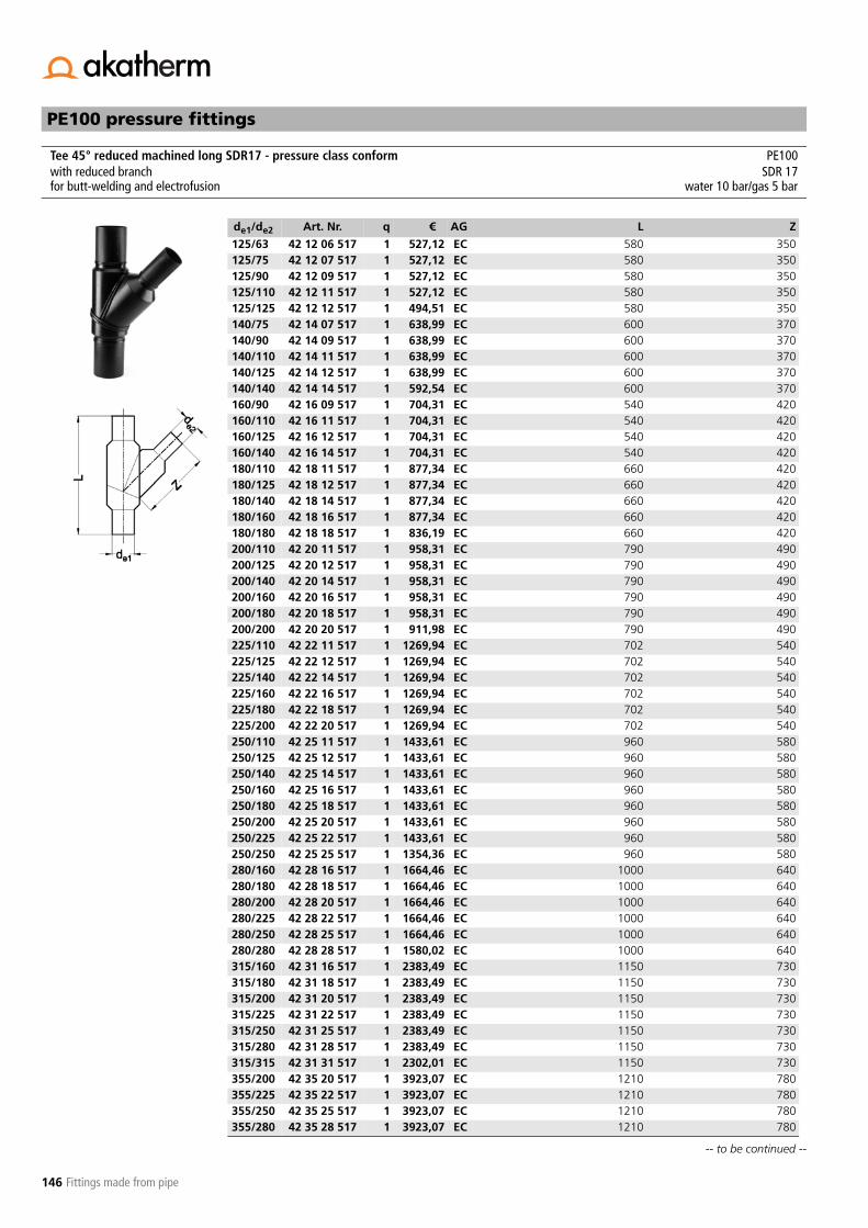
146
-- to be continued --
PE100 pressure fittings
Fittings made from pipe
Tee 45° reduced machined long SDR17 - pressure class conform PE100with reduced branch SDR 17for butt-welding and electrofusion water 10 bar/gas 5 bar
de1/de2 Art. Nr. q € AG L Z
125/63 42 12 06 517 1 527,12 EC 580 350125/75 42 12 07 517 1 527,12 EC 580 350125/90 42 12 09 517 1 527,12 EC 580 350125/110 42 12 11 517 1 527,12 EC 580 350125/125 42 12 12 517 1 494,51 EC 580 350140/75 42 14 07 517 1 638,99 EC 600 370140/90 42 14 09 517 1 638,99 EC 600 370140/110 42 14 11 517 1 638,99 EC 600 370140/125 42 14 12 517 1 638,99 EC 600 370140/140 42 14 14 517 1 592,54 EC 600 370160/90 42 16 09 517 1 704,31 EC 540 420160/110 42 16 11 517 1 704,31 EC 540 420160/125 42 16 12 517 1 704,31 EC 540 420160/140 42 16 14 517 1 704,31 EC 540 420180/110 42 18 11 517 1 877,34 EC 660 420180/125 42 18 12 517 1 877,34 EC 660 420180/140 42 18 14 517 1 877,34 EC 660 420180/160 42 18 16 517 1 877,34 EC 660 420180/180 42 18 18 517 1 836,19 EC 660 420200/110 42 20 11 517 1 958,31 EC 790 490200/125 42 20 12 517 1 958,31 EC 790 490200/140 42 20 14 517 1 958,31 EC 790 490200/160 42 20 16 517 1 958,31 EC 790 490200/180 42 20 18 517 1 958,31 EC 790 490200/200 42 20 20 517 1 911,98 EC 790 490225/110 42 22 11 517 1 1269,94 EC 702 540225/125 42 22 12 517 1 1269,94 EC 702 540225/140 42 22 14 517 1 1269,94 EC 702 540225/160 42 22 16 517 1 1269,94 EC 702 540225/180 42 22 18 517 1 1269,94 EC 702 540225/200 42 22 20 517 1 1269,94 EC 702 540250/110 42 25 11 517 1 1433,61 EC 960 580250/125 42 25 12 517 1 1433,61 EC 960 580250/140 42 25 14 517 1 1433,61 EC 960 580250/160 42 25 16 517 1 1433,61 EC 960 580250/180 42 25 18 517 1 1433,61 EC 960 580250/200 42 25 20 517 1 1433,61 EC 960 580250/225 42 25 22 517 1 1433,61 EC 960 580250/250 42 25 25 517 1 1354,36 EC 960 580280/160 42 28 16 517 1 1664,46 EC 1000 640280/180 42 28 18 517 1 1664,46 EC 1000 640280/200 42 28 20 517 1 1664,46 EC 1000 640280/225 42 28 22 517 1 1664,46 EC 1000 640280/250 42 28 25 517 1 1664,46 EC 1000 640280/280 42 28 28 517 1 1580,02 EC 1000 640315/160 42 31 16 517 1 2383,49 EC 1150 730315/180 42 31 18 517 1 2383,49 EC 1150 730315/200 42 31 20 517 1 2383,49 EC 1150 730315/225 42 31 22 517 1 2383,49 EC 1150 730315/250 42 31 25 517 1 2383,49 EC 1150 730315/280 42 31 28 517 1 2383,49 EC 1150 730315/315 42 31 31 517 1 2302,01 EC 1150 730355/200 42 35 20 517 1 3923,07 EC 1210 780355/225 42 35 22 517 1 3923,07 EC 1210 780355/250 42 35 25 517 1 3923,07 EC 1210 780355/280 42 35 28 517 1 3923,07 EC 1210 780

147
Tee 45° reduced machined long SDR17 - pressure class conform - continuation -PE100 pressure fittings
Fittings made from pipe
60° on request.Pressure class guaranteed, all branches extended with pipe.Fabrication on order, returning not possible.
355/315 42 35 31 517 1 3923,07 EC 1210 780355/355 42 35 35 517 1 3772,70 EC 1210 780400/200 42 40 20 517 1 4700,64 EC 1270 840400/225 42 40 22 517 1 4700,64 EC 1270 840400/250 42 40 25 517 1 4700,64 EC 1270 840400/280 42 40 28 517 1 4700,64 EC 1270 840400/315 42 40 31 517 1 4700,64 EC 1270 840400/355 42 40 35 517 1 4700,64 EC 1270 840400/400 42 40 40 517 1 4517,85 EC 1270 840450/250 42 45 25 517 1 6042,51 EC 1340 900450/280 42 45 28 517 1 6042,51 EC 1340 900450/315 42 45 31 517 1 6042,51 EC 1340 900450/355 42 45 35 517 1 6042,51 EC 1340 900450/400 42 45 40 517 1 6042,51 EC 1340 900450/450 42 45 45 517 1 6042,51 EC 1340 900500/500 42 50 50 517 1 7996,32 EC 1410 960560/560 42 56 56 517 1 10298,41 EC 1500 1030630/630 42 63 63 517 1 13137,39 EC 1600 1110
de1/de2 Art. Nr. q € AG L Z

148
-- to be continued --
PE100 pressure fittings
Fittings made from pipe
Tee 45° reduced machined long SDR11 - pressure class conform PE100with reduced branch SDR 11for butt-welding and electrofusion water 16 bar/gas 10 bar
de1/de2 Art. Nr. q € AG L Z
125/63 42 12 06 511 1 544,58 EC 580 350125/75 42 12 07 511 1 544,58 EC 580 350125/90 42 12 09 511 1 544,58 EC 580 350125/110 42 12 11 511 1 544,58 EC 580 350125/125 42 12 12 511 1 511,98 EC 580 350140/75 42 14 07 511 1 655,64 EC 600 370140/90 42 14 09 511 1 655,64 EC 600 370140/110 42 14 11 511 1 655,64 EC 600 370140/125 42 14 12 511 1 655,64 EC 600 370140/140 42 14 14 511 1 608,81 EC 600 370160/90 42 16 09 511 1 742,71 EC 540 420160/110 42 16 11 511 1 742,71 EC 540 420160/125 42 16 12 511 1 742,71 EC 540 420160/140 42 16 14 511 1 742,71 EC 540 420180/110 42 18 11 511 1 922,05 EC 660 420180/125 42 18 12 511 1 922,05 EC 660 420180/140 42 18 14 511 1 922,05 EC 660 420180/160 42 18 16 511 1 922,05 EC 660 420180/180 42 18 18 511 1 880,38 EC 660 420200/110 42 20 11 511 1 996,63 EC 790 490200/125 42 20 12 511 1 996,63 EC 790 490200/140 42 20 14 511 1 996,63 EC 790 490200/160 42 20 16 511 1 996,63 EC 790 490200/180 42 20 18 511 1 996,63 EC 790 490200/200 42 20 20 511 1 946,43 EC 790 490225/110 42 22 11 511 1 1315,03 EC 702 540225/125 42 22 12 511 1 1315,03 EC 702 540225/140 42 22 14 511 1 1315,03 EC 702 540225/160 42 22 16 511 1 1315,03 EC 702 540225/180 42 22 18 511 1 1315,03 EC 702 540225/200 42 22 20 511 1 1315,03 EC 702 540250/110 42 25 11 511 1 1486,44 EC 960 580250/125 42 25 12 511 1 1486,44 EC 960 580250/140 42 25 14 511 1 1486,44 EC 960 580250/160 42 25 16 511 1 1486,44 EC 960 580250/180 42 25 18 511 1 1486,44 EC 960 580250/200 42 25 20 511 1 1486,44 EC 960 580250/225 42 25 22 511 1 1486,44 EC 960 580250/250 42 25 25 511 1 1403,34 EC 960 580280/160 42 28 16 511 1 1726,73 EC 1000 640280/180 42 28 18 511 1 1726,73 EC 1000 640280/200 42 28 20 511 1 1726,73 EC 1000 640280/225 42 28 22 511 1 1726,73 EC 1000 640280/250 42 28 25 511 1 1726,73 EC 1000 640280/280 42 28 28 511 1 1645,15 EC 1000 640315/160 42 31 16 511 1 2497,59 EC 1150 730315/180 42 31 18 511 1 2497,59 EC 1150 730315/200 42 31 20 511 1 2497,59 EC 1150 730315/225 42 31 22 511 1 2497,59 EC 1150 730315/250 42 31 25 511 1 2497,59 EC 1150 730315/280 42 31 28 511 1 2497,59 EC 1150 730315/315 42 31 31 511 1 2423,42 EC 1150 730355/200 42 35 20 511 1 4110,03 EC 1210 780355/225 42 35 22 511 1 4110,03 EC 1210 780355/250 42 35 25 511 1 4110,03 EC 1210 780355/280 42 35 28 511 1 4110,03 EC 1210 780

149
Tee 45° reduced machined long SDR11 - pressure class conform - continuation -PE100 pressure fittings
Fittings made from pipe
60° on request.Pressure class guaranteed, all branches extended with pipe.Fabrication on order, returning not possible.
355/315 42 35 31 511 1 4110,03 EC 1210 780355/355 42 35 35 511 1 3943,39 EC 1210 780400/200 42 40 20 511 1 4878,95 EC 1270 840400/225 42 40 22 511 1 4878,95 EC 1270 840400/250 42 40 25 511 1 4878,95 EC 1270 840400/280 42 40 28 511 1 4878,95 EC 1270 840400/315 42 40 31 511 1 4878,95 EC 1270 840400/355 42 40 35 511 1 4878,95 EC 1270 840400/400 42 40 40 511 1 4734,67 EC 1270 840450/250 42 45 25 511 1 6333,80 EC 1340 900450/280 42 45 28 511 1 6333,80 EC 1340 900450/315 42 45 31 511 1 6333,80 EC 1340 900450/355 42 45 35 511 1 6333,80 EC 1340 900450/400 42 45 40 511 1 6333,80 EC 1340 900450/450 42 45 45 511 1 6106,31 EC 1340 900500/500 42 50 50 511 1 8429,23 EC 1410 960560/560 42 56 56 511 1 10769,44 EC 1500 1030630/630 42 63 63 511 1 13707,69 EC 1600 1110
de1/de2 Art. Nr. q € AG L Z

150
PE100 pressure fittings
Fittings made from pipe
Variances of +/- 3° are possible.
Bend 90° seamless formed R = 1,5 x de SDR 17 PE100SDR 17
for butt-welding and electrofusion water 10 bar/gas 5 bar
de Art. Nr. q € AG Z l R
50 19 05 93 517 1 33,85 EH 250 120 7563 19 06 93 517 1 49,81 EH 270 120 9575 19 07 93 517 1 53,28 EH 300 130 11390 19 09 93 517 1 58,29 EH 300 115 135
110 19 11 93 517 1 72,98 EH 380 150 165125 19 12 93 517 1 84,49 EH 420 160 188140 19 14 93 517 1 97,52 EH 450 165 210160 19 16 93 517 1 110,13 EH 520 195 240180 19 18 93 517 1 174,98 EH 580 215 270200 19 20 93 517 1 211,42 EH 620 225 300225 19 22 93 517 1 249,42 EH 700 255 338250 19 25 93 517 1 314,76 EH 720 240 375280 19 28 93 517 1 354,86 EH 760 235 420315 19 31 93 517 1 463,49 EH 950 335 473355 19 35 93 517 1 608,58 EH *
* fabrication on order, returning not possible
1100 400 533400 19 40 93 517 1 855,50 EH * 1200 420 600450 19 45 93 517 1 1210,88 EH **
** R = 2,0 x defabrication on order, returning not possible
1350 315 900500 19 50 93 517 1 1737,89 EH ** 1550 385 1000560 19 56 93 517 1 2050,20 EH ** 1900 545 1120630 19 63 93 517 1 2558,21 EH ** 2100 585 1260710 19 71 93 517 1 4831,05 EH ** 2200 570 1440800 19 80 93 517 1 7598,85 EH ** 2200 480 1600

151
PE100 pressure fittings
Fittings made from pipe
Variances of +/- 3° are possible.
Bend 90° seamless formed R = 1,5 x de SDR 11 PE100SDR 11
for butt-welding and electrofusion water 16 bar/gas 10 bar
de Art. Nr. q € AG Z l R
50 19 05 93 511 1 40,98 EH 250 120 7563 19 06 93 511 1 57,38 EH 270 120 9575 19 07 93 511 1 63,69 EH 300 130 11390 19 09 93 511 1 71,37 EH 300 115 135
110 19 11 93 511 1 92,62 EH 380 150 165125 19 12 93 511 1 106,28 EH 420 160 188140 19 14 93 511 1 122,17 EH 450 165 210160 19 16 93 511 1 146,24 EH 520 195 240180 19 18 93 511 1 241,50 EH 580 215 270200 19 20 93 511 1 293,15 EH 620 225 300225 19 22 93 511 1 347,82 EH 700 255 338250 19 25 93 511 1 421,09 EH 720 240 375280 19 28 93 511 1 512,32 EH 760 235 420315 19 31 93 511 1 635,95 EH 950 335 473355 19 35 93 511 1 915,56 EH *
* fabrication on order, returning not possible
1100 400 533400 19 40 93 511 1 1049,74 EH * 1200 420 600450 19 45 93 511 1 1483,40 EH **
** R = 2,0 x defabrication on order, returning not possible
1350 315 900500 19 50 93 511 1 2231,15 EH ** 1550 385 1000560 19 56 93 511 1 2654,98 EH ** 1900 545 1120630 19 63 93 511 1 3410,94 EH ** 2100 585 1260710 19 71 93 511 1 6466,95 EH ** 2200 570 1440

152
PE100 pressure fittings
Fittings made from pipe
Variances of +/- 3° are possible.
Bend 60° seamless formed R = 1,5 x de SDR 17 PE100SDR 17
for butt-welding and electrofusion water 10 bar/gas 5 bar
de Art. Nr. q € AG Z l R
50 19 05 63 517 1 33,57 EH 200 110 7563 19 06 63 517 1 49,15 EH 220 115 9575 19 07 63 517 1 52,28 EH 240 120 11390 19 09 63 517 1 56,46 EH 260 125 135
110 19 11 63 517 1 70,54 EH 280 150 165125 19 12 63 517 1 79,83 EH 300 150 188140 19 14 63 517 1 91,06 EH 400 195 210160 19 16 63 517 1 100,46 EH 430 205 240180 19 18 63 517 1 160,79 EH 450 205 270200 19 20 63 517 1 194,16 EH 500 230 300225 19 22 63 517 1 230,66 EH 550 250 338250 19 25 63 517 1 280,39 EH 600 265 375280 19 28 63 517 1 312,05 EH 630 270 420315 19 31 63 517 1 407,03 EH 830 390 473355 19 35 63 517 1 627,77 EH *
* fabrication on order, returning not possible
900 415 533400 19 40 63 517 1 871,36 EH * 1000 455 600450 19 45 63 517 1 1047,46 EH **
** R = 2,0 x defabrication on order, returning not possible
1115 415 900500 19 50 63 517 1 1436,25 EH ** 1300 505 1000560 19 56 63 517 1 1844,58 EH ** 1450 560 1120630 19 63 63 517 1 2292,11 EH ** 1600 610 1260710 19 71 63 517 1 4747,05 EH ** 1700 570 1440800 19 80 63 517 1 7067,55 EH ** 1700 480 1600

153
PE100 pressure fittings
Fittings made from pipe
Variances of +/- 3° are possible.
Bend 60° seamless formed R = 1,5 x de SDR 11 PE100SDR 11
for butt-welding and electrofusion water 16 bar/gas 10 bar
de Art. Nr. q € AG Z l R
50 19 05 63 511 1 40,39 EH 200 110 7563 19 06 63 511 1 56,58 EH 220 115 9575 19 07 63 511 1 62,04 EH 240 120 11390 19 09 63 511 1 68,72 EH 260 125 135
110 19 11 63 511 1 88,95 EH 280 150 165125 19 12 63 511 1 99,10 EH 300 150 188140 19 14 63 511 1 111,56 EH 400 195 210160 19 16 63 511 1 130,95 EH 430 205 240180 19 18 63 511 1 219,05 EH 450 205 270200 19 20 63 511 1 265,42 EH 500 230 300225 19 22 63 511 1 318,83 EH 550 250 338250 19 25 63 511 1 372,36 EH 600 265 375280 19 28 63 511 1 444,72 EH 630 270 420315 19 31 63 511 1 542,70 EH 830 390 473355 19 35 63 511 1 974,07 EH *
* fabrication on order, returning not possible
900 415 533400 19 40 63 511 1 1071,27 EH * 1000 455 600450 19 45 63 511 1 1316,46 EH **
** R = 2,0 x defabrication on order, returning not possible
1115 415 900500 19 50 63 511 1 1843,88 EH ** 1300 505 1000560 19 56 63 511 1 2388,88 EH ** 1450 560 1120630 19 63 63 511 1 3066,22 EH ** 1600 610 1260710 19 71 63 511 1 6375,60 EH ** 1700 570 1600

154
PE100 pressure fittings
Fittings made from pipe
Variances of +/- 3° are possible.
Bend 45° seamless formed R = 1,5 x de SDR 17 PE100SDR 17
for butt-welding and electrofusion water 10 bar/gas 5 bar
de Art. Nr. q € AG Z l R
50 19 05 48 517 1 33,57 EH 170 100 7563 19 06 48 517 1 49,15 EH 180 100 9575 19 07 48 517 1 52,28 EH 200 100 11390 19 09 48 517 1 56,46 EH 220 100 135
110 19 11 48 517 1 70,54 EH 240 150 165125 19 12 48 517 1 79,83 EH 270 150 188140 19 14 48 517 1 91,06 EH 300 150 210160 19 16 48 517 1 100,46 EH 330 180 240180 19 18 48 517 1 160,79 EH 380 185 270200 19 20 48 517 1 194,16 EH 430 215 300225 19 22 48 517 1 230,66 EH 500 250 338250 19 25 48 517 1 280,39 EH 530 260 375280 19 28 48 517 1 312,05 EH 550 260 420315 19 31 48 517 1 407,03 EH 650 315 473355 19 35 48 517 1 627,77 EH *
* fabrication on order, returning not possible
650 300 533400 19 40 48 517 1 871,36 EH * 730 335 600450 19 45 48 517 1 1047,46 EH **
** R = 2,0 x defabrication on order, returning not possible
830 320 900500 19 50 48 517 1 1436,25 EH ** 1100 480 1000560 19 56 48 517 1 1835,41 EH ** 1115 455 1120630 19 63 48 517 1 2289,41 EH ** 1350 580 1260710 19 71 48 517 1 4469,85 EH ** 1400 570 1440800 19 80 48 517 1 6837,60 EH ** 1500 480 1600

155
PE100 pressure fittings
Fittings made from pipe
Variances of +/- 3° are possible.
Bend 45° seamless formed R = 1,5 x de SDR 11 PE100SDR 11
for butt-welding and electrofusion water 16 bar/gas 10 bar
de Art. Nr. q € AG Z l R
50 19 05 48 511 1 40,39 EH 170 100 7563 19 06 48 511 1 56,58 EH 180 100 9575 19 07 48 511 1 62,04 EH 200 100 11390 19 09 48 511 1 68,72 EH 220 100 135
110 19 11 48 511 1 88,95 EH 240 150 165125 19 12 48 511 1 99,10 EH 270 150 188140 19 14 48 511 1 111,56 EH 300 150 210160 19 16 48 511 1 130,95 EH 330 180 240180 19 18 48 511 1 219,05 EH 380 185 270200 19 20 48 511 1 265,42 EH 430 215 300225 19 22 48 511 1 318,83 EH 500 250 338250 19 25 48 511 1 372,36 EH 530 260 375280 19 28 48 511 1 444,72 EH 550 260 420315 19 31 48 511 1 542,70 EH 650 315 473355 19 35 48 511 1 974,07 EH *
* fabrication on order, returning not possible
650 300 533400 19 40 48 511 1 1071,27 EH * 730 335 600450 19 45 48 511 1 1316,46 EH **
** R = 2,0 x defabrication on order, returning not possible
830 320 900500 19 50 48 511 1 1843,88 EH ** 1100 480 1000560 19 56 48 511 1 2377,58 EH ** 1115 455 1120630 19 63 48 511 1 3055,50 EH ** 1350 580 1260710 19 71 48 511 1 6058,50 EH ** 1400 570 1440

156
PE100 pressure fittings
Fittings made from pipe
Variances of +/- 3° are possible.
Bend 30° seamless formed R = 1,5 x de SDR 17 PE100SDR 17
for butt-welding and electrofusion water 10 bar/gas 5 bar
de Art. Nr. q € AG Z l R
50 19 05 33 517 1 33,57 EH 170 105 7563 19 06 33 517 1 49,15 EH 180 105 9575 19 07 33 517 1 52,28 EH 200 120 11390 19 09 33 517 1 56,46 EH 220 130 135
110 19 11 33 517 1 70,54 EH 230 130 165125 19 12 33 517 1 79,83 EH 260 150 188140 19 14 33 517 1 91,06 EH 300 170 210160 19 16 33 517 1 100,46 EH 300 180 240180 19 18 33 517 1 160,79 EH 330 180 270200 19 20 33 517 1 194,16 EH 420 235 300225 19 22 33 517 1 230,66 EH 450 250 338250 19 25 33 517 1 280,39 EH 530 300 375280 19 28 33 517 1 312,05 EH 530 290 420315 19 31 33 517 1 407,03 EH 650 365 473355 19 35 33 517 1 627,77 EH *
* fabrication on order, returning not possible
650 355 533400 19 40 33 517 1 871,36 EH * 690 370 600450 19 45 33 517 1 1047,46 EH **
** R = 2,0 x defabrication on order, returning not possible
730 340 900500 19 50 33 517 1 1436,25 EH ** 1100 580 1000560 19 56 33 517 1 1835,41 EH ** 1100 560 1120630 19 63 33 517 1 2289,41 EH ** 1250 640 1260710 19 71 33 517 1 4469,85 EH ** 1350 570 1440800 19 80 33 517 1 6837,60 EH ** 1450 480 1600
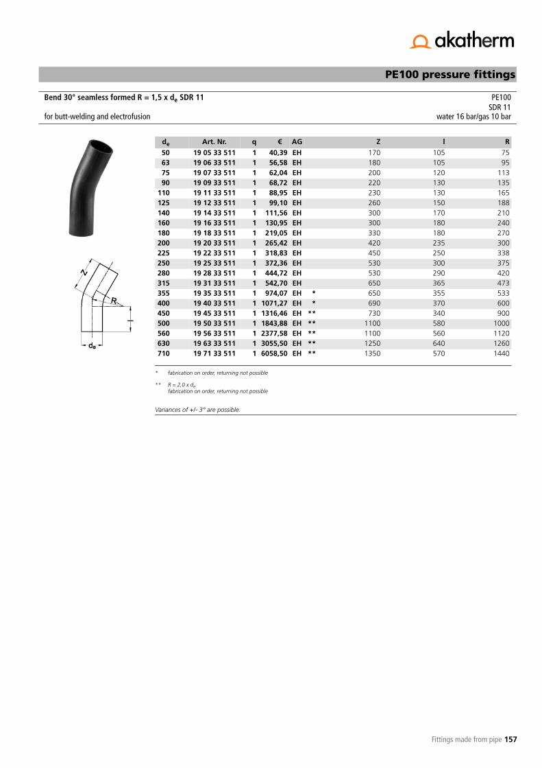
157
PE100 pressure fittings
Fittings made from pipe
Variances of +/- 3° are possible.
Bend 30° seamless formed R = 1,5 x de SDR 11 PE100SDR 11
for butt-welding and electrofusion water 16 bar/gas 10 bar
de Art. Nr. q € AG Z l R
50 19 05 33 511 1 40,39 EH 170 105 7563 19 06 33 511 1 56,58 EH 180 105 9575 19 07 33 511 1 62,04 EH 200 120 11390 19 09 33 511 1 68,72 EH 220 130 135
110 19 11 33 511 1 88,95 EH 230 130 165125 19 12 33 511 1 99,10 EH 260 150 188140 19 14 33 511 1 111,56 EH 300 170 210160 19 16 33 511 1 130,95 EH 300 180 240180 19 18 33 511 1 219,05 EH 330 180 270200 19 20 33 511 1 265,42 EH 420 235 300225 19 22 33 511 1 318,83 EH 450 250 338250 19 25 33 511 1 372,36 EH 530 300 375280 19 28 33 511 1 444,72 EH 530 290 420315 19 31 33 511 1 542,70 EH 650 365 473355 19 35 33 511 1 974,07 EH *
* fabrication on order, returning not possible
650 355 533400 19 40 33 511 1 1071,27 EH * 690 370 600450 19 45 33 511 1 1316,46 EH **
** R = 2,0 x defabrication on order, returning not possible
730 340 900500 19 50 33 511 1 1843,88 EH ** 1100 580 1000560 19 56 33 511 1 2377,58 EH ** 1100 560 1120630 19 63 33 511 1 3055,50 EH ** 1250 640 1260710 19 71 33 511 1 6058,50 EH ** 1350 570 1440

158
PE100 pressure fittings
Fittings made from pipe
Variances of +/- 3° are possible.
Bend 22° seamless formed R = 1,5 x de SDR 17 PE100SDR 17
for butt-welding and electrofusion water 10 bar/gas 5 bar
de Art. Nr. q € AG Z l R
50 19 05 25 517 1 33,57 EH 170 110 7563 19 06 25 517 1 49,15 EH 180 110 9575 19 07 25 517 1 52,28 EH 200 125 11390 19 09 25 517 1 56,46 EH 220 135 135
110 19 11 25 517 1 70,54 EH 230 150 165125 19 12 25 517 1 79,83 EH 260 155 188140 19 14 25 517 1 91,06 EH 300 180 210160 19 16 25 517 1 100,46 EH 300 180 240180 19 18 25 517 1 160,79 EH 330 195 270200 19 20 25 517 1 194,16 EH 420 250 300225 19 22 25 517 1 230,66 EH 450 270 338250 19 25 25 517 1 280,39 EH 530 320 375280 19 28 25 517 1 312,05 EH 530 315 420315 19 31 25 517 1 407,03 EH 630 375 473355 19 35 25 517 1 627,77 EH *
* fabrication on order, returning not possible
650 380 533400 19 40 25 517 1 871,36 EH * 660 380 600450 19 45 25 517 1 1047,46 EH **
** R = 2,0 x defabrication on order, returning not possible
660 340 900500 19 50 25 517 1 1436,25 EH ** 1000 565 1000560 19 56 25 517 1 1835,41 EH ** 1000 550 1120630 19 63 25 517 1 2289,41 EH ** 1100 600 1260710 19 71 25 517 1 4469,85 EH ** 1300 570 1440800 19 80 25 517 1 6837,60 EH ** 1400 480 1600

159
PE100 pressure fittings
Fittings made from pipe
Variances of +/- 3° are possible.
Bend 22° seamless formed R = 1,5 x de SDR 11 PE100SDR 11
for butt-welding and electrofusion water 16 bar/gas 10 bar
de Art. Nr. q € AG Z l R
50 19 05 25 511 1 40,39 EH 170 110 7563 19 06 25 511 1 56,58 EH 180 110 9575 19 07 25 511 1 62,04 EH 200 125 11390 19 09 25 511 1 68,72 EH 220 135 135
110 19 11 25 511 1 88,95 EH 230 150 165125 19 12 25 511 1 99,10 EH 260 155 188140 19 14 25 511 1 111,56 EH 300 180 210160 19 16 25 511 1 130,95 EH 300 180 240180 19 18 25 511 1 219,05 EH 330 195 270200 19 20 25 511 1 265,42 EH 420 250 300225 19 22 25 511 1 318,83 EH 450 270 338250 19 25 25 511 1 372,36 EH 530 320 375280 19 28 25 511 1 444,72 EH 530 315 420315 19 31 25 511 1 542,70 EH 630 375 473355 19 35 25 511 1 974,07 EH *
* fabrication on order, returning not possible
650 380 533400 19 40 25 511 1 1071,27 EH * 660 380 600450 19 45 25 511 1 1316,46 EH **
** R = 2,0 x defabrication on order, returning not possible
660 340 900500 19 50 25 511 1 1843,88 EH ** 1000 565 1000560 19 56 25 511 1 2377,58 EH ** 1000 550 1120630 19 63 25 511 1 3055,50 EH ** 1100 600 1260710 19 71 25 511 1 6058,50 EH ** 1300 570 1440

160
PE100 pressure fittings
Fittings made from pipe
Variances of +/- 3° are possible.
Bend 11° seamless formed R = 1,5 x de SDR 17 PE100SDR 17
for butt-welding and electrofusion water 10 bar/gas 5 bar
de Art. Nr. q € AG Z l R
50 19 05 14 517 1 33,57 EH 170 115 7563 19 06 14 517 1 49,15 EH 180 120 9575 19 07 14 517 1 52,28 EH 200 130 11390 19 09 14 517 1 56,46 EH 220 145 135
110 19 11 14 517 1 70,54 EH 230 150 165125 19 12 14 517 1 79,83 EH 260 170 188140 19 14 14 517 1 91,06 EH 300 195 210160 19 16 14 517 1 100,46 EH 300 195 240180 19 18 14 517 1 160,79 EH 330 210 270200 19 20 14 517 1 194,16 EH 420 275 300225 19 22 14 517 1 230,66 EH 450 290 338250 19 25 14 517 1 280,39 EH 530 345 375280 19 28 14 517 1 312,05 EH 530 345 420315 19 31 14 517 1 407,03 EH 630 410 473355 19 35 14 517 1 627,77 EH *
* fabrication on order, returning not possible
650 420 533400 19 40 14 517 1 871,36 EH * 660 420 600450 19 45 14 517 1 1047,46 EH **
** R = 2,0 x defabrication on order, returning not possible
660 400 900500 19 50 14 517 1 1436,25 EH ** 1000 630 1000560 19 56 14 517 1 1835,41 EH ** 1000 625 1120630 19 63 14 517 1 2289,41 EH ** 1100 685 1260710 19 71 14 517 1 4469,85 EH ** 1250 570 1440800 19 80 14 517 1 6837,60 EH ** 1350 480 1600

161
PE100 pressure fittings
Fittings made from pipe
Variances of +/- 3° are possible.
Bend 11° seamless formed R = 1,5 x de SDR 11 PE100SDR 11
for butt-welding and electrofusion water 16 bar/gas 10 bar
de Art. Nr. q € AG Z l R
50 19 05 14 511 1 40,39 EH 170 115 7563 19 06 14 511 1 56,58 EH 180 120 9575 19 07 14 511 1 62,04 EH 200 130 11390 19 09 14 511 1 68,72 EH 220 145 135
110 19 11 14 511 1 88,95 EH 230 150 165125 19 12 14 511 1 99,10 EH 260 170 188140 19 14 14 511 1 111,56 EH 300 195 210160 19 16 14 511 1 130,95 EH 300 195 240180 19 18 14 511 1 219,05 EH 330 210 270200 19 20 14 511 1 265,42 EH 420 275 300225 19 22 14 511 1 318,83 EH 450 290 338250 19 25 14 511 1 372,36 EH 530 345 375280 19 28 14 511 1 444,72 EH 530 345 420315 19 31 14 511 1 542,70 EH 630 410 473355 19 35 14 511 1 974,07 EH *
* fabrication on order, returning not possible
650 420 533400 19 40 14 511 1 1071,27 EH * 660 420 600450 19 45 14 511 1 1316,46 EH **
** R = 2,0 x defabrication on order, returning not possible
660 400 900500 19 50 14 511 1 1843,88 EH ** 1000 630 1000560 19 56 14 511 1 2377,58 EH ** 1000 625 1120630 19 63 14 511 1 3055,50 EH ** 1100 685 1260710 19 71 14 511 1 6058,50 EH ** 1250 570 1440

162
PE100 pressure fittings
Fittings made from pipe
Variances of +/- 3° are possible.Fabrication on order, returning not possible.
Variances of +/- 3° are possible.Fabrication on order, returning not possible.
Bend 90° seamless formed R = 2,5 x de SDR 17 PE100SDR 17
for butt-welding and electrofusion water 10 bar/gas 5 bar
de Art. Nr. q € AG Z l R
50 19 05 94 517 1 40,77 EL 375 250 12563 19 06 94 517 1 43,07 EL 405 250 15875 19 07 94 517 1 45,10 EL 435 250 18890 19 09 94 517 1 49,28 EL 475 250 225
110 19 11 94 517 1 64,27 EL 525 250 275125 19 12 94 517 1 77,73 EL 560 250 313140 19 14 94 517 1 95,26 EL 600 250 350160 19 16 94 517 1 126,88 EL 680 280 400180 19 18 94 517 1 192,41 EL 730 280 450200 19 20 94 517 1 236,36 EL 800 300 500225 19 22 94 517 1 289,57 EL 890 330 563250 19 25 94 517 1 397,95 EL 985 360 625280 19 28 94 517 1 560,70 EL 1060 360 625315 19 31 94 517 1 637,35 EL 1245 460 788355 19 35 94 517 1 828,45 EL 1345 460 888400 19 40 94 517 1 997,50 EL 1480 480 1000450 19 45 94 517 1 1550,85 EL 1665 540 1125
Bend 90° seamless formed R = 2,5 x de SDR 11 PE100SDR 11
for butt-welding and electrofusion water 16 bar/gas 10 bar
de Art. Nr. q € AG Z l R
50 19 05 94 511 1 43,07 EL 375 250 12563 19 06 94 511 1 45,47 EL 405 250 15875 19 07 94 511 1 48,52 EL 435 250 18890 19 09 94 511 1 55,38 EL 475 250 225
110 19 11 94 511 1 82,43 EL 525 250 275125 19 12 94 511 1 101,99 EL 560 250 313140 19 14 94 511 1 141,98 EL 600 250 350160 19 16 94 511 1 170,56 EL 680 280 400180 19 18 94 511 1 235,98 EL 730 280 450200 19 20 94 511 1 305,45 EL 800 300 500225 19 22 94 511 1 380,00 EL 890 330 563250 19 25 94 511 1 571,20 EL 985 360 625280 19 28 94 511 1 683,55 EL 1060 360 625315 19 31 94 511 1 770,70 EL 1245 460 788355 19 35 94 511 1 952,35 EL 1345 460 888400 19 40 94 511 1 1254,75 EL 1480 480 1000450 19 45 94 511 1 1747,20 EL 1665 540 1125

163
PE100 pressure fittings
Fittings made from pipe
Composition Art. Nr.:xx = 64 for 60°xx = 49 for 45°xx = 34 for 30°xx = 26 for 22°xx = 15 for 11°
Dimensions apply for bend 45°, 30°, 22° and 11°.
Variances of +/- 3° are possible.Fabrication on order, returning not possible.
Bend seamless formed R = 2,5 x de SDR 17 60°/45°/30°/22°/11° PE100SDR 17
for butt-welding and electrofusion water 10 bar/gas 5 bar
de Art. Nr. q € AG Z l R
50 19 05 xx 517 1 40,10 EL - - 12563 19 06 xx 517 1 42,27 EL - - 15875 19 07 xx 517 1 44,45 EL - - 18890 19 09 xx 517 1 48,25 EL - - 225
110 19 11 xx 517 1 62,60 EL - - 275125 19 12 xx 517 1 75,97 EL - - 313140 19 14 xx 517 1 85,64 EL - - 350160 19 16 xx 517 1 118,46 EL - - 400180 19 18 xx 517 1 181,49 EL - - 450200 19 20 xx 517 1 214,10 EL - - 500225 19 22 xx 517 1 240,18 EL - - 563250 19 25 xx 517 1 392,07 EL - - 625280 19 28 xx 517 1 555,56 EL - - 700315 19 31 xx 517 1 616,04 EL - - 788355 19 35 xx 517 1 761,72 EL - - 888400 19 40 xx 517 1 929,72 EL - - 1000450 19 45 xx 517 1 1335,20 EL - - 1125

164
PE100 pressure fittings
Fittings made from pipe
Composition Art. Nr.:xx = 64 for 60°xx = 49 for 45°xx = 34 for 30°xx = 26 for 22°xx = 15 for 11°
Dimensions apply for bend 45°, 30°, 22° and 11°.
Variances of +/- 3° are possible.Fabrication on order, returning not possible.
Bend seamless formed R = 2,5 x de SDR 11 60°/45°/30°/22°/11° PE100SDR 11
for butt-welding and electrofusion water 16 bar/gas 10 bar
de Art. Nr. q € AG Z l R
50 19 05 xx 511 1 41,95 EL - - 12563 19 06 xx 511 1 44,23 EL - - 15875 19 07 xx 511 1 47,39 EL - - 18890 19 09 xx 511 1 54,34 EL - - 225
110 19 11 xx 511 1 77,60 EL - - 275125 19 12 xx 511 1 89,33 EL - - 313140 19 14 xx 511 1 132,58 EL - - 350160 19 16 xx 511 1 158,67 EL - - 400180 19 18 xx 511 1 218,44 EL - - 450200 19 20 xx 511 1 286,90 EL - - 500225 19 22 xx 511 1 240,18 EL - - 563250 19 25 xx 511 1 560,07 EL - - 625280 19 28 xx 511 1 660,87 EL - - 700315 19 31 xx 511 1 734,84 EL - - 788355 19 35 xx 511 1 921,90 EL - - 888400 19 40 xx 511 1 1215,45 EL - - 1000450 19 45 xx 511 1 1601,83 EL - - 1125
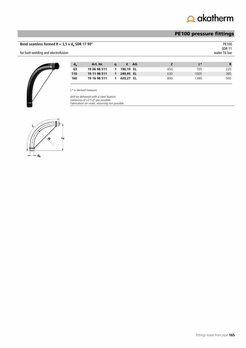
165
PE100 pressure fittings
Fittings made from pipe
L* is derived measure
Will be delivered with a steel fixation.Variances of +5°/-3° are possible.Fabrication on order, returning not possible.
Bend seamless formed R = 3,5 x de SDR 17 90° PE100SDR 11
for butt-welding and electrofusion water 16 bar
de Art. Nr. q € AG Z L* R
63 19 06 98 511 1 190,19 EL 450 705 220110 19 11 98 511 1 249,95 EL 630 1005 385160 19 16 98 511 1 429,27 EL 800 1380 560

166
PE100 pressure fittings
Fittings made from pipe
Composition Art. Nr.:xx = 95 for 90°xx = 65 for 60°
Dimensions apply for bend 90°.
Bends 90°/60° with R > 2,5 x de are provided with a steel fixation.
Variances of +5°/-3° are possible.Fabrication on order, returning not possible.
Composition Art. Nr.:xx = 95 for 90°xx = 65 for 60°
Dimensions apply for bend 90°.
Bends 90°/60° with R > 2,5 x de are provided with a steel fixation.
Variances of +5°/-3° are possible.Fabrication on order, returning not possible.
Bend seamless formed Ri = 700 mm SDR 17 90°/60° PE100SDR 17
for butt-welding and electrofusion water 10 bar/gas 5 bar
de Art. Nr. q € AG Z L R
50 19 05 xx 517 1 197,79 EL 1715 3000 72563 19 06 xx 517 1 202,14 EL 1715 3000 73175 19 07 xx 517 1 209,75 EL 1715 3000 73790 19 09 xx 517 1 226,04 EL 1715 3000 745
110 19 11 xx 517 1 270,61 EL 1715 3000 755125 19 12 xx 517 1 318,42 EL 1715 3000 762140 19 14 xx 517 1 346,68 EL 1715 3000 770160 19 16 xx 517 1 433,62 EL 1715 3000 780180 19 18 xx 517 1 476,00 EL 1715 3000 790200 19 20 xx 517 1 592,28 EL 1715 3000 800225 19 22 xx 517 1 695,52 EL 1715 3000 812250 19 25 xx 517 1 782,46 EL 1715 3000 825280 19 28 xx 517 1 927,00 EL 1715 3000 840
Bend seamless formed Ri = 700 mm SDR 11 90°/60° PE100SDR 11
for butt-welding and electrofusion water 16 bar/gas 10 bar
de Art. Nr. q € AG Z L R
50 19 05 xx 511 1 202,14 EL 1715 3000 72563 19 06 xx 511 1 213,00 EL 1715 3000 73175 19 07 xx 511 1 221,70 EL 1715 3000 73790 19 09 xx 511 1 245,61 EL 1715 3000 745
110 19 11 xx 511 1 277,13 EL 1715 3000 755125 19 12 xx 511 1 344,51 EL 1715 3000 762140 19 14 xx 511 1 373,84 EL 1715 3000 770160 19 16 xx 511 1 478,17 EL 1715 3000 780180 19 18 xx 511 1 529,25 EL 1715 3000 790200 19 20 xx 511 1 631,41 EL 1715 3000 800225 19 22 xx 511 1 735,74 EL 1715 3000 812250 19 25 xx 511 1 811,81 EL 1715 3000 825280 19 28 xx 511 1 986,77 EL 1715 3000 840

167
PE100 pressure fittings
Fittings made from pipe
Composition Art. Nr.:xx = 50 for 45°xx = 35 for 30°xx = 27 for 22°xx = 16 for 11°
Variances of +5°/-3° are possible.Fabrication on order, returning not possible.
Composition Art. Nr.:xx = 50 for 45°xx = 35 for 30°xx = 27 for 22°xx = 16 for 11°
Variances of +5°/-3° are possible.Fabrication on order, returning not possible.
Bend seamless formed Ri = 700 mm SDR 17 45°/30°/22°/11° PE100SDR 17
for butt-welding and electrofusion water 10 bar/gas 5 bar
de Art. Nr. q € AG Z L R
50 19 05 xx 517 1 114,11 EL 1500 3000 72563 19 06 xx 517 1 122,81 EL 1500 3000 73175 19 07 xx 517 1 126,06 EL 1500 3000 73790 19 09 xx 517 1 158,67 EL 1500 3000 745
110 19 11 xx 517 1 185,84 EL 1500 3000 755125 19 12 xx 517 1 230,39 EL 1500 3000 762140 19 14 xx 517 1 260,82 EL 1500 3000 770160 19 16 xx 517 1 301,04 EL 1500 3000 780180 19 18 xx 517 1 341,24 EL 1500 3000 790200 19 20 xx 517 1 395,58 EL 1500 3000 800225 19 22 xx 517 1 461,87 EL 1500 3000 812250 19 25 xx 517 1 522,73 EL 1500 3000 825280 19 28 xx 517 1 589,02 EL 1500 3000 840
Bend seamless formed Ri = 700 mm SDR 11 45°/30°/22°/11° PE100SDR 11
for butt-welding and electrofusion water 16 bar/gas 10 bar
de Art. Nr. q € AG Z L R
50 19 05 xx 511 1 127,16 EL 1500 3000 72563 19 06 xx 511 1 140,20 EL 1500 3000 73175 19 07 xx 511 1 154,32 EL 1500 3000 73790 19 09 xx 511 1 179,32 EL 1500 3000 745
110 19 11 xx 511 1 209,75 EL 1500 3000 755125 19 12 xx 511 1 253,22 EL 1500 3000 762140 19 14 xx 511 1 280,38 EL 1500 3000 770160 19 16 xx 511 1 332,55 EL 1500 3000 780180 19 18 xx 511 1 383,63 EL 1500 3000 790200 19 20 xx 511 1 434,70 EL 1500 3000 800225 19 22 xx 511 1 518,39 EL 1500 3000 812250 19 25 xx 511 1 562,94 EL 1500 3000 825280 19 28 xx 511 1 641,18 EL 1500 3000 840

168
PE100 pressure fittings
Fittings made from pipe
Composition Art. Nr.:xx = 96 for 90°xx = 66 for 60°
Dimensions apply for bend 90°.
Bends 90°/60° with R > 2,5 x de are provided with a steel fixation.
Variances of +5°/-3° are possible.Fabrication on order, returning not possible.
Bend seamless formed Ri = 1100 mm SDR 17 90°/60° PE100SDR 17
for butt-welding and electrofusion water 10 bar/gas 5 bar
de Art. Nr. q € AG Z L R
50 19 05 xx 517 1 216,27 EL 1972 3300 112563 19 06 xx 517 1 221,70 EL 1972 3300 113175 19 07 xx 517 1 227,14 EL 1972 3300 113790 19 09 xx 517 1 256,47 EL 1972 3300 1145
110 19 11 xx 517 1 281,47 EL 1972 3300 1155125 19 12 xx 517 1 318,42 EL 1972 3300 1162140 19 14 xx 517 1 364,07 EL 1972 3300 1170160 19 16 xx 517 1 512,95 EL 1972 3300 1180180 19 18 xx 517 1 565,11 EL 1972 3300 1190200 19 20 xx 517 1 659,66 EL 1972 3300 1200225 19 22 xx 517 1 730,30 EL 1972 3300 1212250 19 25 xx 517 1 802,02 EL 1972 3300 1225280 19 28 xx 517 1 946,56 EL 1972 3300 1240315 19 31 xx 517 1 1135,66 EL 1972 3300 1257355 19 35 xx 517 1 1298,67 EL 1972 3300 1277400 19 40 xx 517 1 1581,23 EL 1972 3300 1300

169
PE100 pressure fittings
Fittings made from pipe
Composition Art. Nr.:xx = 96 for 90°xx = 66 for 60°
Dimensions apply for bend 90°.
Bends 90°/60° with R > 2,5 x de are provided with a steel fixation.
Variances of +5°/-3° are possible.Fabrication on order, returning not possible.
Bend seamless formed Ri = 1100 mm SDR 11 90°/60° PE100SDR 11
for butt-welding and electrofusion water 16 bar/gas 10 bar
de Art. Nr. q € AG Z L R
50 19 05 xx 511 1 220,62 EL 1972 3300 112563 19 06 xx 511 1 231,48 EL 1972 3300 113175 19 07 xx 511 1 247,78 EL 1972 3300 113790 19 09 xx 511 1 273,86 EL 1972 3300 1145
110 19 11 xx 511 1 306,46 EL 1972 3300 1155125 19 12 xx 511 1 354,28 EL 1972 3300 1162140 19 14 xx 511 1 391,23 EL 1972 3300 1170160 19 16 xx 511 1 545,55 EL 1972 3300 1180180 19 18 xx 511 1 592,28 EL 1972 3300 1190200 19 20 xx 511 1 715,08 EL 1972 3300 1200225 19 22 xx 511 1 785,73 EL 1972 3300 1212250 19 25 xx 511 1 829,20 EL 1972 3300 1225280 19 28 xx 511 1 986,77 EL 1972 3300 1240315 19 31 xx 511 1 1179,13 EL 1972 3300 1257355 19 35 xx 511 1 1353,01 EL 1972 3300 1277400 19 40 xx 511 1 1755,11 EL 1972 3300 1300
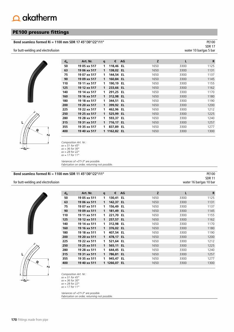
170
PE100 pressure fittings
Fittings made from pipe
Composition Art. Nr.:xx = 51 for 45°xx = 36 for 30°xx = 28 for 22°xx = 17 for 11°
Variances of +5°/-3° are possible.Fabrication on order, returning not possible.
Composition Art. Nr.:xx = 51 for 45°xx = 36 for 30°xx = 28 for 22°xx = 17 for 11°
Variances of +5°/-3° are possible.Fabrication on order, returning not possible.
Bend seamless formed Ri = 1100 mm SDR 17 45°/30°/22°/11° PE100SDR 17
for butt-welding and electrofusion water 10 bar/gas 5 bar
de Art. Nr. q € AG Z L R
50 19 05 xx 517 1 118,46 EL 1650 3300 112563 19 06 xx 517 1 138,02 EL 1650 3300 113175 19 07 xx 517 1 144,54 EL 1650 3300 113790 19 09 xx 517 1 160,84 EL 1650 3300 1145
110 19 11 xx 517 1 190,19 EL 1650 3300 1155125 19 12 xx 517 1 233,66 EL 1650 3300 1162140 19 14 xx 517 1 291,25 EL 1650 3300 1170160 19 16 xx 517 1 312,98 EL 1650 3300 1180180 19 18 xx 517 1 344,51 EL 1650 3300 1190200 19 20 xx 517 1 399,92 EL 1650 3300 1200225 19 22 xx 517 1 462,96 EL 1650 3300 1212250 19 25 xx 517 1 525,99 EL 1650 3300 1225280 19 28 xx 517 1 593,37 EL 1650 3300 1240315 19 31 xx 517 1 716,17 EL 1650 3300 1257355 19 35 xx 517 1 837,89 EL 1650 3300 1277400 19 40 xx 517 1 1162,82 EL 1650 3300 1300
Bend seamless formed Ri = 1100 mm SDR 11 45°/30°/22°/11° PE100SDR 11
for butt-welding and electrofusion water 16 bar/gas 10 bar
de Art. Nr. q € AG Z L R
50 19 05 xx 511 1 130,41 EL 1650 3300 112563 19 06 xx 511 1 142,37 EL 1650 3300 113175 19 07 xx 511 1 156,49 EL 1650 3300 113790 19 09 xx 511 1 181,49 EL 1650 3300 1145
110 19 11 xx 511 1 221,70 EL 1650 3300 1155125 19 12 xx 511 1 257,57 EL 1650 3300 1162140 19 14 xx 511 1 312,98 EL 1650 3300 1170160 19 16 xx 511 1 376,02 EL 1650 3300 1180180 19 18 xx 511 1 407,54 EL 1650 3300 1190200 19 20 xx 511 1 478,17 EL 1650 3300 1200225 19 22 xx 511 1 521,64 EL 1650 3300 1212250 19 25 xx 511 1 565,11 EL 1650 3300 1225280 19 28 xx 511 1 644,45 EL 1650 3300 1240315 19 31 xx 511 1 786,81 EL 1650 3300 1257355 19 35 xx 511 1 945,47 EL 1650 3300 1277400 19 40 xx 511 1 1266,07 EL 1650 3300 1300

171
PE100 pressure fittings
Fittings made from pipe
Composition Art. Nr.:xx = 97 for 90°xx = 67 for 60°
Dimensions apply for bend 90°.
Bends 90°/60° with R > 2,5 x de are provided with a steel fixation.
Variances of +5°/-3° are possible.Fabrication on order, returning not possible.
Bend seamless formed Ri = 1750 mm SDR 17 90°/60° PE100SDR 17
for butt-welding and electrofusion water 10 bar/gas 5 bar
de Art. Nr. q € AG Z L R
50 19 05 xx 517 1 222,79 EL 3030 5000 177563 19 06 xx 517 1 233,66 EL 3030 5000 178175 19 07 xx 517 1 246,70 EL 3030 5000 178790 19 09 xx 517 1 272,78 EL 3030 5000 1795
110 19 11 xx 517 1 312,98 EL 3030 5000 1805125 19 12 xx 517 1 454,26 EL 3030 5000 1812140 19 14 xx 517 1 492,30 EL 3030 5000 1820160 19 16 xx 517 1 586,85 EL 3030 5000 1830180 19 18 xx 517 1 643,36 EL 3030 5000 1840200 19 20 xx 517 1 752,03 EL 3030 5000 1850225 19 22 xx 517 1 859,62 EL 3030 5000 1862250 19 25 xx 517 1 944,39 EL 3030 5000 1875280 19 28 xx 517 1 1124,79 EL 3030 5000 1890315 19 31 xx 517 1 1358,44 EL 3030 5000 1907355 19 35 xx 517 1 1608,39 EL 3030 5000 1927400 19 40 xx 517 1 1956,15 EL 3030 5000 1950450 19 45 xx 517 1 2320,22 EL 3030 5000 1975500 19 50 xx 517 1 2814,68 EL 3030 5000 2000560 19 56 xx 517 1 3314,59 EL 3030 5000 2030630 19 63 xx 517 1 4020,98 EL 3030 5000 2065

172
PE100 pressure fittings
Fittings made from pipe
Composition Art. Nr.:xx = 97 for 90°xx = 67 for 60°
Dimensions apply for bend 90°.
Bends 90°/60° with R > 2,5 x de are provided with a steel fixation.
Variances of +5°/-3° are possible.Fabrication on order, returning not possible.
Bend seamless formed Ri = 1750 mm SDR 11 90°/60° PE100SDR 11
for butt-welding and electrofusion water 16 bar/gas 10 bar
de Art. Nr. q € AG Z L R
50 19 05 xx 511 1 232,56 EL 3030 5000 177563 19 06 xx 511 1 251,04 EL 3030 5000 178175 19 07 xx 511 1 268,43 EL 3030 5000 178790 19 09 xx 511 1 303,21 EL 3030 5000 1795
110 19 11 xx 511 1 355,37 EL 3030 5000 1805125 19 12 xx 511 1 504,25 EL 3030 5000 1812140 19 14 xx 511 1 556,42 EL 3030 5000 1820160 19 16 xx 511 1 669,44 EL 3030 5000 1830180 19 18 xx 511 1 748,78 EL 3030 5000 1840200 19 20 xx 511 1 881,36 EL 3030 5000 1850225 19 22 xx 511 1 1019,37 EL 3030 5000 1862250 19 25 xx 511 1 1141,09 EL 3030 5000 1875280 19 28 xx 511 1 1374,74 EL 3030 5000 1890315 19 31 xx 511 1 1679,03 EL 3030 5000 1907355 19 35 xx 511 1 2015,93 EL 3030 5000 1927400 19 40 xx 511 1 2472,36 EL 3030 5000 1950450 19 45 xx 511 1 2977,70 EL 3030 5000 1975500 19 50 xx 511 1 3483,04 EL 3030 5000 2000560 19 56 xx 511 1 4216,59 EL 3030 5000 2030630 19 63 xx 511 1 5428,32 EL 3030 5000 2065

173
PE100 pressure fittings
Fittings made from pipe
Composition Art. Nr.:xx = 52 for 45°xx = 37 for 30°xx = 29 for 22°xx = 18 for 11°
Variances of +5°/-3° are possible.Fabrication on order, returning not possible.
Bend seamless formed Ri = 1750 mm SDR 17 45°/30°/22°/11° PE100SDR 17
for butt-welding and electrofusion water 10 bar/gas 5 bar
de Art. Nr. q € AG Z L R
50 19 05 xx 517 1 136,93 EL 2550 5000 177563 19 06 xx 517 1 155,41 EL 2550 5000 178175 19 07 xx 517 1 157,58 EL 2550 5000 178790 19 09 xx 517 1 185,84 EL 2550 5000 1795
110 19 11 xx 517 1 214,10 EL 2550 5000 1805125 19 12 xx 517 1 340,16 EL 2550 5000 1812140 19 14 xx 517 1 373,84 EL 2550 5000 1820160 19 16 xx 517 1 407,54 EL 2550 5000 1830180 19 18 xx 517 1 458,61 EL 2550 5000 1840200 19 20 xx 517 1 514,04 EL 2550 5000 1850225 19 22 xx 517 1 600,98 EL 2550 5000 1862250 19 25 xx 517 1 675,96 EL 2550 5000 1875280 19 28 xx 517 1 783,55 EL 2550 5000 1890315 19 31 xx 517 1 1004,16 EL 2550 5000 1907355 19 35 xx 517 1 1255,20 EL 2550 5000 1927400 19 40 xx 517 1 1499,72 EL 2550 5000 1950450 19 45 xx 517 1 1863,78 EL 2550 5000 1975500 19 50 xx 517 1 2276,75 EL 2550 5000 2000560 19 56 xx 517 1 2733,18 EL 2550 5000 2030630 19 63 xx 517 1 3363,50 EL 2550 5000 2065
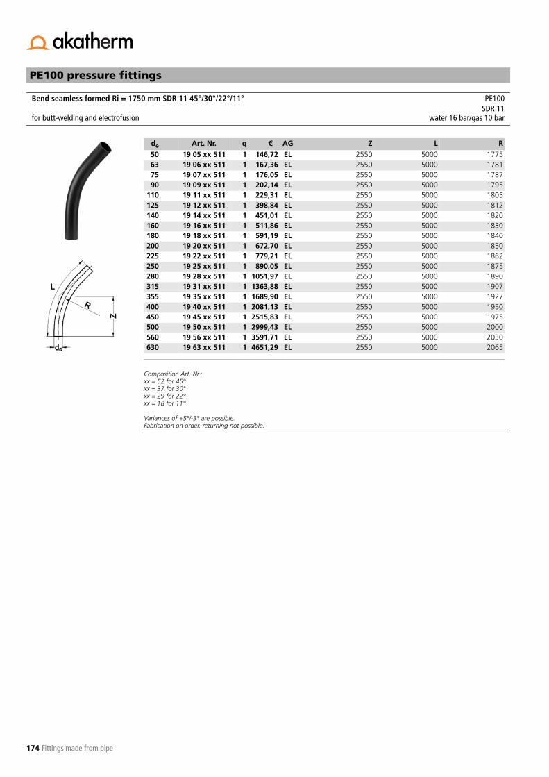
174
PE100 pressure fittings
Fittings made from pipe
Composition Art. Nr.:xx = 52 for 45°xx = 37 for 30°xx = 29 for 22°xx = 18 for 11°
Variances of +5°/-3° are possible.Fabrication on order, returning not possible.
Bend seamless formed Ri = 1750 mm SDR 11 45°/30°/22°/11° PE100SDR 11
for butt-welding and electrofusion water 16 bar/gas 10 bar
de Art. Nr. q € AG Z L R
50 19 05 xx 511 1 146,72 EL 2550 5000 177563 19 06 xx 511 1 167,36 EL 2550 5000 178175 19 07 xx 511 1 176,05 EL 2550 5000 178790 19 09 xx 511 1 202,14 EL 2550 5000 1795
110 19 11 xx 511 1 229,31 EL 2550 5000 1805125 19 12 xx 511 1 398,84 EL 2550 5000 1812140 19 14 xx 511 1 451,01 EL 2550 5000 1820160 19 16 xx 511 1 511,86 EL 2550 5000 1830180 19 18 xx 511 1 591,19 EL 2550 5000 1840200 19 20 xx 511 1 672,70 EL 2550 5000 1850225 19 22 xx 511 1 779,21 EL 2550 5000 1862250 19 25 xx 511 1 890,05 EL 2550 5000 1875280 19 28 xx 511 1 1051,97 EL 2550 5000 1890315 19 31 xx 511 1 1363,88 EL 2550 5000 1907355 19 35 xx 511 1 1689,90 EL 2550 5000 1927400 19 40 xx 511 1 2081,13 EL 2550 5000 1950450 19 45 xx 511 1 2515,83 EL 2550 5000 1975500 19 50 xx 511 1 2999,43 EL 2550 5000 2000560 19 56 xx 511 1 3591,71 EL 2550 5000 2030630 19 63 xx 511 1 4651,29 EL 2550 5000 2065
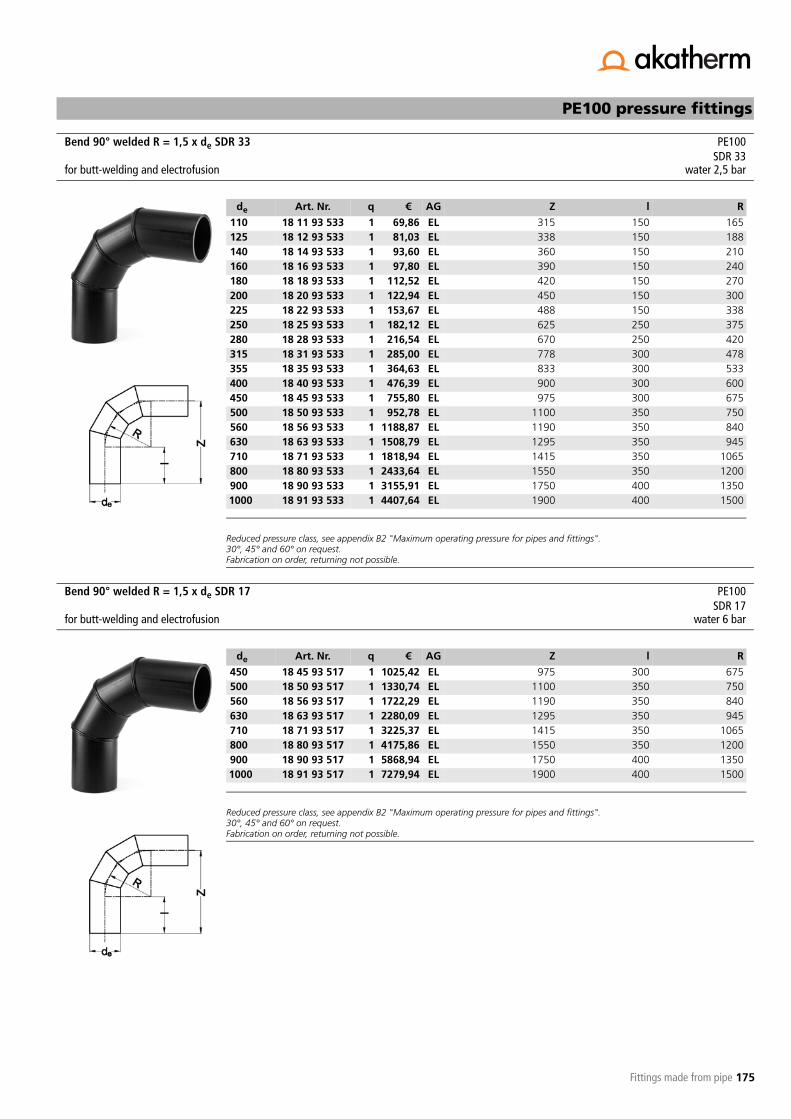
175
PE100 pressure fittings
Fittings made from pipe
Reduced pressure class, see appendix B2 "Maximum operating pressure for pipes and fittings".30°, 45° and 60° on request.Fabrication on order, returning not possible.
Reduced pressure class, see appendix B2 "Maximum operating pressure for pipes and fittings".30°, 45° and 60° on request.Fabrication on order, returning not possible.
Bend 90° welded R = 1,5 x de SDR 33 PE100SDR 33
for butt-welding and electrofusion water 2,5 bar
de Art. Nr. q € AG Z l R
110 18 11 93 533 1 69,86 EL 315 150 165125 18 12 93 533 1 81,03 EL 338 150 188140 18 14 93 533 1 93,60 EL 360 150 210160 18 16 93 533 1 97,80 EL 390 150 240180 18 18 93 533 1 112,52 EL 420 150 270200 18 20 93 533 1 122,94 EL 450 150 300225 18 22 93 533 1 153,67 EL 488 150 338250 18 25 93 533 1 182,12 EL 625 250 375280 18 28 93 533 1 216,54 EL 670 250 420315 18 31 93 533 1 285,00 EL 778 300 478355 18 35 93 533 1 364,63 EL 833 300 533400 18 40 93 533 1 476,39 EL 900 300 600450 18 45 93 533 1 755,80 EL 975 300 675500 18 50 93 533 1 952,78 EL 1100 350 750560 18 56 93 533 1 1188,87 EL 1190 350 840630 18 63 93 533 1 1508,79 EL 1295 350 945710 18 71 93 533 1 1818,94 EL 1415 350 1065800 18 80 93 533 1 2433,64 EL 1550 350 1200900 18 90 93 533 1 3155,91 EL 1750 400 13501000 18 91 93 533 1 4407,64 EL 1900 400 1500
Bend 90° welded R = 1,5 x de SDR 17 PE100SDR 17
for butt-welding and electrofusion water 6 bar
de Art. Nr. q € AG Z l R
450 18 45 93 517 1 1025,42 EL 975 300 675500 18 50 93 517 1 1330,74 EL 1100 350 750560 18 56 93 517 1 1722,29 EL 1190 350 840630 18 63 93 517 1 2280,09 EL 1295 350 945710 18 71 93 517 1 3225,37 EL 1415 350 1065800 18 80 93 517 1 4175,86 EL 1550 350 1200900 18 90 93 517 1 5868,94 EL 1750 400 13501000 18 91 93 517 1 7279,94 EL 1900 400 1500

176
PE100 pressure fittings
Fittings made from pipe
Reduced pressure class, see appendix B2 "Maximum operating pressure for pipes and fittings".30°, 45° and 60° on request.Fabrication on order, returning not possible.
Bend 90° welded R = 1,5 x de SDR 11 PE100SDR 11
for butt-welding and electrofusion water 10 bar
de Art. Nr. q € AG Z l R
450 18 45 93 511 1 1323,88 EL 975 300 675500 18 50 93 511 1 1696,88 EL 1100 350 750560 18 56 93 511 1 2658,31 EL 1190 350 840630 18 63 93 511 1 3370,41 EL 1295 350 945
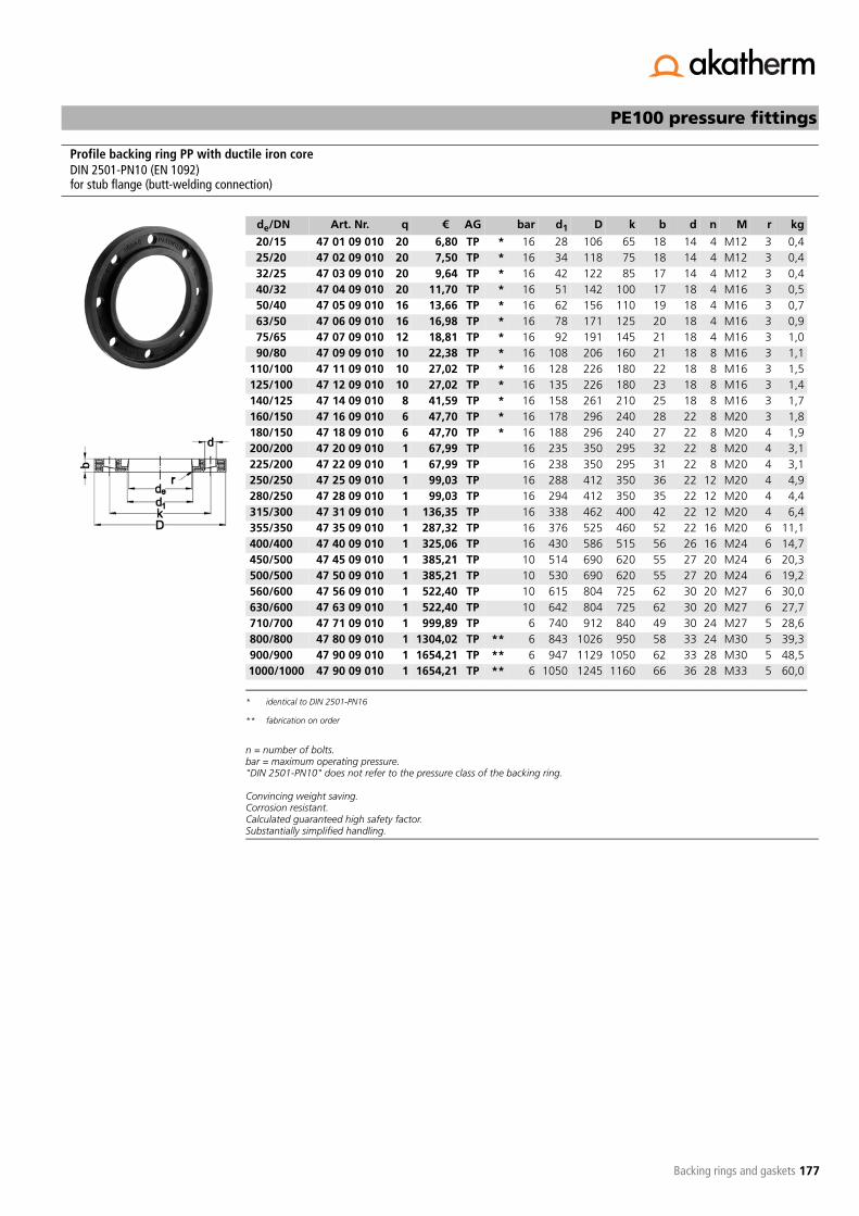
177
PE100 pressure fittings
Backing rings and gaskets
n = number of bolts.bar = maximum operating pressure."DIN 2501-PN10" does not refer to the pressure class of the backing ring.
Convincing weight saving.Corrosion resistant.Calculated guaranteed high safety factor.Substantially simplified handling.
Profile backing ring PP with ductile iron core DIN 2501-PN10 (EN 1092)for stub flange (butt-welding connection)
de/DN Art. Nr. q € AG bar d1 D k b d n M r kg
20/15 47 01 09 010 20 6,80 TP *
* identical to DIN 2501-PN16
16 28 106 65 18 14 4 M12 3 0,425/20 47 02 09 010 20 7,50 TP * 16 34 118 75 18 14 4 M12 3 0,432/25 47 03 09 010 20 9,64 TP * 16 42 122 85 17 14 4 M12 3 0,440/32 47 04 09 010 20 11,70 TP * 16 51 142 100 17 18 4 M16 3 0,550/40 47 05 09 010 16 13,66 TP * 16 62 156 110 19 18 4 M16 3 0,763/50 47 06 09 010 16 16,98 TP * 16 78 171 125 20 18 4 M16 3 0,975/65 47 07 09 010 12 18,81 TP * 16 92 191 145 21 18 4 M16 3 1,090/80 47 09 09 010 10 22,38 TP * 16 108 206 160 21 18 8 M16 3 1,1
110/100 47 11 09 010 10 27,02 TP * 16 128 226 180 22 18 8 M16 3 1,5125/100 47 12 09 010 10 27,02 TP * 16 135 226 180 23 18 8 M16 3 1,4140/125 47 14 09 010 8 41,59 TP * 16 158 261 210 25 18 8 M16 3 1,7160/150 47 16 09 010 6 47,70 TP * 16 178 296 240 28 22 8 M20 3 1,8180/150 47 18 09 010 6 47,70 TP * 16 188 296 240 27 22 8 M20 4 1,9200/200 47 20 09 010 1 67,99 TP 16 235 350 295 32 22 8 M20 4 3,1225/200 47 22 09 010 1 67,99 TP 16 238 350 295 31 22 8 M20 4 3,1250/250 47 25 09 010 1 99,03 TP 16 288 412 350 36 22 12 M20 4 4,9280/250 47 28 09 010 1 99,03 TP 16 294 412 350 35 22 12 M20 4 4,4315/300 47 31 09 010 1 136,35 TP 16 338 462 400 42 22 12 M20 4 6,4355/350 47 35 09 010 1 287,32 TP 16 376 525 460 52 22 16 M20 6 11,1400/400 47 40 09 010 1 325,06 TP 16 430 586 515 56 26 16 M24 6 14,7450/500 47 45 09 010 1 385,21 TP 10 514 690 620 55 27 20 M24 6 20,3500/500 47 50 09 010 1 385,21 TP 10 530 690 620 55 27 20 M24 6 19,2560/600 47 56 09 010 1 522,40 TP 10 615 804 725 62 30 20 M27 6 30,0630/600 47 63 09 010 1 522,40 TP 10 642 804 725 62 30 20 M27 6 27,7710/700 47 71 09 010 1 999,89 TP 6 740 912 840 49 30 24 M27 5 28,6800/800 47 80 09 010 1 1304,02 TP **
** fabrication on order
6 843 1026 950 58 33 24 M30 5 39,3900/900 47 90 09 010 1 1654,21 TP ** 6 947 1129 1050 62 33 28 M30 5 48,51000/1000 47 90 09 010 1 1654,21 TP ** 6 1050 1245 1160 66 36 28 M33 5 60,0

178
PE100 pressure fittings
Backing rings and gaskets
n = number of bolts.bar = maximum operating pressure."DIN 2501-PN10" does not refer to the pressure class of the backing ring.
n = number of bolts.bar = maximum operating pressure.ANSI B16.5 class 150
Profile backing ring PP with ductile iron core DIN 2501-PN10 (EN 1092)for flange adaptor (socket connection)
de/DN Art. Nr. q € AG bar d1 D k b d n M r kg
20/15 47 01 09 010 20 6,80 TP *
* identical to profile backing ring PP with ductile iron core DIN 2501-PN10 for stub flange
16 28 106 65 18 14 4 M12 3 0,425/20 47 02 09 010 20 7,50 TP * 16 34 118 75 18 14 4 M12 3 0,432/25 47 03 09 010 20 9,64 TP * 16 42 122 85 17 14 4 M12 3 0,440/32 47 04 09 010 20 11,70 TP * 16 51 142 100 17 18 4 M16 3 0,550/40 47 05 09 010 16 13,66 TP * 16 62 156 110 19 18 4 M16 3 0,763/50 47 06 09 010 16 16,98 TP * 16 78 171 125 20 18 4 M16 3 0,975/65 47 07 09 010 12 18,81 TP * 16 92 191 145 21 18 4 M16 3 1,090/80 47 09 19 010 10 22,38 TP 16 110 206 160 21 18 8 M16 3 1,2
110/100 47 11 19 010 10 27,02 TP 16 133 226 180 22 18 8 M16 3 1,5140/125 47 14 19 010 8 41,59 TP 16 167 261 210 26 18 8 M16 3 1,9160/150 47 16 19 010 6 47,70 TP 16 190 296 240 28 22 8 M16 3 2,6225/200 47 22 19 010 1 67,99 TP 16 250 350 295 23 22 8 M20 3 2,7250/250 47 25 19 010 1 99,03 TP 16 277 403 350 35 22 12 M20 4 5,3280/250 47 28 19 010 1 99,03 TP 16 310 403 350 31 22 12 M20 4 3,8315/300 47 31 19 010 1 136,35 TP 16 348 458 400 37 22 12 M20 4 5,7
Profile backing ring PP with ductile iron core ANSI 150 lbfor stub flange
DN/de Art. Nr. q € AG bar d1 D k b d n kg
63/2" 47 83 09 010 10 23,44 TA 16 78 164 121 18 19 4 0,890/3" 47 85 09 010 10 29,58 TA 16 108 196 153 19 19 4 1,0
110/4" 47 86 09 010 8 35,43 TA 16 128 237 191 25 19 8 1,8160/6" 47 87 09 010 5 60,66 TA 16 178 297 242 30 22 8 3,2225/8" 47 88 09 010 1 86,51 TA 16 238 354 299 34 22 8 5,1250/10" 47 89 09 010 1 103,50 TA 16 288 425 362 39 26 12 6,9315/12" 47 90 29 010 1 146,73 TA 16 338 497 432 51 26 12 12,8

179
PE100 pressure fittings
Backing rings and gaskets
n = number of bolts.bar = maximum operating pressure."DIN 2501-PN10" does not refer to the pressure class of the backing ring.
Backing ring PP with ductile iron core DIN 2501-PN10 (EN 1092)for stub flange
de/DN Art. Nr. q € AG bar d1 D k b d n M kg
20/15 47 01 08 010 1 7,15 TV *
* identical to DIN 2501-PN16
16 28 95 65 12 14 4 M12 0,325/20 47 02 08 010 1 7,90 TV * 16 34 105 75 14 14 4 M12 0,332/25 47 03 08 010 1 10,15 TV * 16 42 115 85 14 14 4 M12 0,440/32 47 04 08 010 1 12,32 TV * 16 51 140 100 16 18 4 M16 0,750/40 47 05 08 010 1 14,37 TV * 16 62 150 110 16 18 4 M16 0,763/50 47 06 08 010 1 17,88 TV * 16 78 165 125 19 18 4 M16 0,875/65 47 07 08 010 1 19,80 TV * 16 92 185 145 19 18 4 M16 1,190/80 47 09 08 010 1 23,57 TV * 16 108 200 160 21 18 8 M16 1,4
110/100 47 11 08 010 1 28,46 TV * 16 128 220 180 22 18 8 M16 1,6125/100 47 12 08 010 1 28,46 TV * 16 135 220 180 22 18 8 M16 1,4140/125 47 14 08 010 1 43,80 TV * 16 158 250 210 26 18 8 M16 2,0160/150 47 16 08 010 1 50,24 TV * 16 178 285 240 27 22 8 M20 2,5180/150 47 18 08 010 1 50,24 TV * 16 188 285 240 27 22 8 M20 2,3200/200 47 20 08 010 1 71,61 TV 16 235 340 295 28 22 8 M20 3,2225/200 47 22 08 010 1 71,61 TV 16 238 340 295 28 22 8 M20 3,2250/250 47 25 08 010 1 104,28 TV 16 288 406 350 31 22 12 M20 6,4280/250 47 28 08 010 1 104,28 TV 16 294 406 350 31 22 12 M20 6,3315/300 47 31 08 010 1 143,60 TV 16 338 460 400 34 22 12 M20 9,8355/350 47 35 08 010 1 302,59 TV 16 377 520 460 39 23 16 M20 15,0400/400 47 40 08 010 1 342,33 TV 16 430 580 515 43 27 16 M24 18,1450/500 47 45 08 010 1 405,68 TV 10 517 678 620 45 26 20 M24 25,0500/500 47 50 08 010 1 405,68 TV 10 533 678 620 45 26 20 M24 23,4560/600 47 56 08 010 1 550,15 TV 10 618 790 725 50 30 20 M27 33,7630/600 47 63 08 010 1 550,15 TV 10 645 790 725 50 30 20 M27 32,6

180
PE100 pressure fittings
Backing rings and gaskets
n = number of bolts.bar = maximum operating pressure.ANSI B16.5 class 150
Backing ring PP with ductile iron coreANSI 150 lbfor stub flange
DN/de Art. Nr. q € AG bar d1 D k b d n kg
20/½" 47 78 08 010 1 9,09 TA 16 28 95 60,5 12 16 4 0,325/¾" 47 79 08 010 1 11,34 TA 16 34 102 69,9 12 16 4 0,332/1" 47 80 08 010 1 13,38 TA 16 42 114 79,3 16 16 4 0,440/1¼" 47 81 08 010 1 15,40 TA 16 51 130 88,9 16 16 4 0,550/1½" 47 82 08 010 1 19,20 TA 16 62 133 98,6 18 16 4 0,663/2" 47 83 08 010 1 23,87 TA 16 78 162 120,6 18 20 4 0,975/2½" 47 84 08 010 1 29,49 TA 16 92 184 139,7 18 20 4 1,190/3" 47 85 08 010 1 34,58 TA 16 111 194 152,4 18 20 4 1,0
110/4" 47 86 08 010 1 45,12 TA 16 133 229 190,5 18 20 8 1,6160/6" 47 87 08 010 1 85,21 TA 16 178 283 241,3 24 22 8 2,5200/8" 47 88 08 010 1 123,28 TA 16 236 345 298,5 24 22 8 3,4250/10" 47 89 08 010 1 158,75 TA 16 288 412 361,9 27 25 12 5,9315/12" 47 90 08 010 1 244,88 TA 16 338 487 431,8 32 25 12 12,8355/14" 47 91 08 010 1 418,25 TA 16 376 533 476,2 42 28,5 12 15,7400/16" 47 92 08 010 1 478,52 TA 16 430 596 539,7 44 28,5 16 17,6

181
PE100 pressure fittings
Backing rings and gaskets
n = number of bolts.bar = maximum operating pressure."DIN 2501-PN10" does not refer to the pressure class of the backing ring.
Profile backing ring ductile iron GGG40 epoxy coatedDIN 2501-PN10 (EN 1092)for stub flange
de/DN Art. Nr. q € AG bar d1 D k b d n M r kg
50/40 47 05 13 010 16 14,14 TS *
* identical to DIN 2501-PN16
16 62 150 110 16 18 4 M16 3 1,063/50 47 06 13 010 16 16,19 TS * 16 78 165 125 16 18 4 M16 3 1,175/65 47 07 13 010 10 18,23 TS * 16 92 185 145 16 18 4 M16 3 1,490/80 47 09 13 010 10 21,36 TS * 16 108 200 160 19 18 8 M16 3 1,6
110/100 47 11 13 010 10 23,59 TS * 16 128 220 180 19 18 8 M16 3 1,8125/100 47 12 13 010 9 23,59 TS * 16 135 220 180 19 18 8 M16 3 1,7140/125 47 14 13 010 8 29,67 TS * 16 158 250 210 19 18 8 M16 3 2,1160/150 47 16 13 010 6 37,57 TS * 16 178 285 240 19 22 8 M20 3 2,6180/150 47 18 13 010 6 37,57 TS * 10 188 285 240 19 22 8 M20 3 2,5200/200 47 20 13 010 1 54,35 TS 10 235 340 295 18 22 8 M20 3 3,5225/200 47 22 13 010 1 54,35 TS 10 238 340 295 18 22 8 M20 3 3,5250/250 47 25 13 010 1 79,55 TS 10 288 395 350 22 22 12 M20 3 5,3280/250 47 28 13 010 1 79,55 TS 10 294 395 350 22 22 12 M20 3 5,1315/300 47 31 13 010 1 98,69 TS 10 338 445 400 26 22 12 M20 3 6,6355/350 47 35 13 010 1 163,92 TS 10 376 505 460 30 22 16 M20 4 11,3400/400 47 40 13 010 1 208,86 TS 10 430 565 515 34 26 16 M24 4 14,2450/500 47 45 13 010 1 319,50 TS 10 517 670 620 42 26 20 M24 6 21,5500/500 47 50 13 010 1 319,50 TS 10 533 670 620 38 26 20 M24 4 18,7560/600 47 56 13 010 1 489,51 TS 10 618 785 725 50 30 20 M27 7 34,8630/600 47 63 13 010 1 489,51 TS 10 645 785 725 40 30 20 M27 4 26,4710/700 47 71 13 010 1 736,63 TS 6 740 900 840 45 30 24 M27 5 36,4800/800 47 80 13 010 1 972,58 TS **
** fabrication on order
6 843 1015 950 53 33 24 M30 5 50,5900/900 47 90 13 010 1 1090,07 TS ** 6 947 1115 1050 56 33 28 M30 5 55,81000/1000 47 91 13 010 1 1364,30 TS ** 6 1050 1230 1160 62 36 28 M33 5 71,11200/1200 47 92 13 010 1 1912,75 TS ** 4 1260 1455 1380 68 39 32 M36 6 1011400/1400 47 93 13 010 1 1760,07 TS ** 4 1441 1675 1590 72 42 36 M39 6 1431600/1600 47 94 13 010 1 o.r. TP ** 4 1644 1915 1820 84 48 40 M45 6 203

182
PE100 pressure fittings
Backing rings and gaskets
n = number of bolts.bar = maximum operating pressure."DIN 2501-PN16" does not refer to the pressure class of the backing ring.
Profile backing ring ductile iron GGG40 epoxy coatedDIN 2501-PN16 (EN 1092)for stub flange
de/DN Art. Nr. q € AG bar d1 D k b d n M r kg
50/40 47 05 13 010 16 14,14 TS 16 62 150 110 16 18 4 M16 3 1,063/50 47 06 13 010 16 16,19 TS 16 78 165 125 16 18 4 M16 3 1,175/65 47 07 13 010 10 18,23 TS 16 92 185 145 16 18 4 M16 3 1,490/80 47 09 13 010 10 21,36 TS 16 108 200 160 19 18 8 M16 3 1,6
110/100 47 11 13 010 10 23,59 TS 16 128 220 180 19 18 8 M16 3 1,8125/100 47 12 13 010 9 23,59 TS 16 135 220 180 19 18 8 M16 3 1,7140/125 47 14 13 010 8 29,67 TS 16 158 250 210 19 18 8 M16 3 2,1160/150 47 16 13 010 6 37,57 TS 16 178 285 240 19 22 8 M20 3 2,6180/150 47 18 13 010 6 37,57 TS 16 188 285 240 19 22 8 M20 3 2,5200/200 47 20 13 016 1 58,07 TS 16 235 340 295 23 22 12 M20 3 4,0225/200 47 22 13 016 1 58,07 TS 16 238 340 295 23 22 12 M20 3 3,9250/250 47 25 13 016 1 94,46 TS 16 288 405 355 29 26 12 M24 3 6,6280/250 47 28 13 016 1 94,46 TS 16 294 405 355 29 26 12 M24 3 6,5315/300 47 31 13 016 1 120,68 TS 16 338 460 410 34 26 12 M24 3 8,6355/350 47 35 13 016 1 208,06 TS 16 376 520 470 39 26 16 M24 4 14,4400/400 47 40 13 016 1 246,24 TS 16 430 580 525 43 30 16 M27 4 17,0450/500 47 40 13 016 1 246,24 TS 16 517 715 650 46 33 20 M30 6,5 29,8500/500 47 40 13 016 1 246,24 TS 16 533 650 650 46 33 20 M30 7 27,3560/600 47 40 13 016 1 246,24 TS 16 618 840 770 55 36 20 M33 6 46,5630/600 47 40 13 016 1 246,24 TS 16 645 840 770 55 36 20 M33 6 37,2

183
PE100 pressure fittings
Backing rings and gaskets
n = number of bolts.bar = maximum operating pressure."DIN 2501-PN10" does not refer to the pressure class of the backing ring.
Backing ring GRP standard type DIN 2501-PN10 (EN 1092)for stub flange
de/DN Art. Nr. q € AG bar d1 D k b d n M kg
20/15 47 01 07 010 1 7,46 TG *
* also suitable for flange adaptor (socket connection)
6 28 95 65 14 14 4 M12 0,225/20 47 02 07 010 1 8,11 TG * 6 34 105 75 14 14 4 M12 0,232/25 47 03 07 010 1 9,21 TG * 6 42 115 85 16 14 4 M12 0,340/32 47 04 07 010 1 11,29 TG * 6 51 140 100 16 18 4 M16 0,450/40 47 05 07 010 1 12,25 TG * 6 62 150 110 16 18 4 M16 0,463/50 47 06 07 010 1 14,21 TG * 6 78 165 125 16 18 4 M16 0,575/65 47 07 07 010 1 17,72 TG * 6 92 185 145 16 18 4 M16 0,690/80 47 09 07 010 1 20,40 TG 6 108 200 160 18 18 8 M16 0,7
110/100 47 11 07 010 1 24,39 TG 6 128 220 180 18 18 8 M16 0,8125/100 47 12 07 010 1 24,39 TG 6 135 220 180 18 18 8 M16 0,7140/125 47 14 07 010 1 29,70 TG 6 158 250 210 18 18 8 M16 1,0160/150 47 16 07 010 1 35,31 TG 6 178 285 240 18 23 8 M20 1,2180/150 47 18 07 010 1 35,31 TG 6 188 285 240 18 23 8 M20 1,1200/200 47 20 07 010 1 51,37 TG 6 235 340 295 25 23 8 M20 2,1225/200 47 22 07 010 1 51,37 TG 6 238 340 295 25 23 8 M20 2,1250/250 47 25 07 010 1 65,44 TG 6 288 395 350 28 23 12 M20 2,7280/250 47 28 07 010 1 65,44 TG 6 294 395 350 28 23 12 M20 2,5315/300 47 31 07 010 1 78,58 TG 6 338 445 400 30 23 12 M20 3,3355/350 47 35 07 010 1 113,03 TG 6 376 505 460 28 23 16 M20 4,2400/400 47 40 07 010 1 125,34 TG 6 430 565 515 32 27 16 M24 6,0450/500 47 45 07 010 1 165,85 TG 6 533 670 620 38 27 20 M24 8,6500/500 47 50 07 010 1 165,85 TG 6 533 670 620 38 27 20 M24 8,6

184
PE100 pressure fittings
Backing rings and gaskets
n = number of bolts.bar = maximum operating pressure."DIN 2501-PN10" does not refer to the pressure class of the backing ring.
Backing ring GRP heavy type DIN 2501-PN10DIN 2501-PN10 (EN 1092)for stub flange
de/DN Art. Nr. q € AG bar d1 D k b d n M kg
63/50 47 06 06 010 1 19,54 TG *
* also suitable for flange adaptor (socket connection)
10 78 165 125 18 18 4 M16 0,575/65 47 07 06 010 1 22,96 TG * 10 92 185 145 20 18 4 M16 0,790/80 47 09 06 010 1 24,71 TG 10 108 200 160 22 18 8 M16 0,8
110/100 47 11 06 010 1 30,09 TG 10 128 220 180 28 18 8 M16 1,2125/100 47 12 06 010 1 30,09 TG 10 135 220 180 28 18 8 M16 1,1140/125 47 14 06 010 1 36,18 TG 10 158 250 210 30 18 8 M16 1,6160/150 47 16 06 010 1 44,90 TG 10 178 285 240 30 23 8 M20 1,9180/150 47 18 06 010 1 44,90 TG 10 188 285 240 30 23 8 M20 1,8200/200 47 20 06 010 1 62,78 TG 10 235 340 295 32 23 8 M20 2,5225/200 47 22 06 010 1 62,78 TG 10 238 340 295 32 23 8 M20 2,4250/250 47 25 06 010 1 77,62 TG 10 288 395 350 34 23 12 M20 3,2280/250 47 28 06 010 1 79,61 TG 10 294 395 350 34 23 12 M20 3,0315/300 47 31 06 010 1 90,18 TG 10 338 445 400 36 23 12 M20 4,0355/350 47 35 06 010 1 144,91 TG 10 376 505 460 38 23 16 M20 5,6400/400 47 40 06 010 1 162,36 TG 10 430 565 515 42 27 16 M24 7,2450/500 47 45 06 010 1 199,29 TG 10 533 670 620 48 27 20 M24 10,4500/500 47 50 06 010 1 199,29 TG 10 533 670 620 48 27 20 M24 10,4560/600 47 56 06 010 1 379,84 TG 10 645 780 725 56 30 20 M27 13,2630/600 47 63 06 010 1 379,84 TG 10 645 780 725 56 30 20 M27 13,2

185
PE100 pressure fittings
Backing rings and gaskets
EPDM O-ring and hot dip galvanised steel backing ring.n = number of bolts.bar = maximum operating pressure.For direct connection of valves without loss of cross section and without changing the nominal size."DIN 2501-PN10" does not refer to the pressure class of the backing ring.
EPDM O-ring and hot dip galvanised steel backing ring.n = number of bolts.bar = maximum operating pressure.For direct connection of valves without loss of cross section and without changing the nominal size."DIN 2501-PN10" does not refer to the pressure class of the backing ring.
Flange connection short SDR 17 PE100DIN 2501-PN10 (EN 1092) SDR 17for butt-welding water 10 bar
de/DN Art. Nr. q € AG bar Z D k b d n M kg
90/65 47 06 09 017 1 231,39 TR 10 90 185 145 30 18 4 M16 2,9110/80 47 08 11 017 1 253,12 TR 10 90 200 160 30 18 8 M16 3,6140/100 47 10 14 017 1 263,03 TR 10 90 220 180 30 18 8 M16 3,6160/125 47 12 16 017 1 300,22 TR 10 100 250 210 35 18 8 M16 4,7180/125 47 12 18 017 1 327,50 TR 10 125 250 210 35 18 8 M16 4,5200/150 47 15 20 017 1 376,94 TR 10 100 285 240 35 23 8 M20 5,7250/200 47 20 25 017 1 435,87 TR 10 100 340 295 40 23 8 M20 8,2315/250 47 25 31 017 1 660,51 TR *
* different construction
10 130 395 350 40 23 12 M20 11,5355/300 47 30 35 017 1 671,60 TR 10 110 445 400 40 23 12 M20 15,1400/350 47 35 40 017 1 798,96 TR 10 130 505 460 60 23 16 M20 21,7450/400 47 40 45 017 1 1027,18 TR 10 130 565 515 60 27 16 M24 29,0560/500 47 50 56 017 1 1237,20 TR 10 140 670 620 60 27 20 M24 42,3
Flange connection short SDR 11 PE100DIN 2501-PN10 (EN 1092) SDR 11for butt-welding water 16 bar
de/DN Art. Nr. q € AG bar Z D k b d n M kg
90/65 47 06 09 011 1 243,64 TR 10 90 185 145 30 18 4 M16 2,9110/80 47 08 11 011 1 266,60 TR 10 90 200 160 30 18 8 M16 3,6140/100 47 10 14 011 1 276,87 TR 10 90 220 180 30 18 8 M16 3,6160/125 47 12 16 011 1 316,03 TR 10 100 250 210 35 18 8 M16 4,7180/125 47 12 18 011 1 344,89 TR 10 125 250 210 35 18 8 M16 4,5200/150 47 15 20 011 1 397,10 TR 10 100 285 240 35 23 8 M20 5,7250/200 47 20 25 011 1 458,82 TR 10 100 340 295 40 23 8 M20 8,2315/250 47 25 31 011 1 695,33 TR *
* different construction
10 130 395 350 40 23 12 M20 11,5355/300 47 30 35 011 1 706,80 TR 10 110 445 400 40 23 12 M20 15,1400/350 47 35 40 011 1 840,88 TR 10 130 505 460 60 23 16 M20 21,7450/400 47 40 45 011 1 1081,36 TR 10 130 565 515 60 27 16 M24 29,0560/500 47 50 56 011 1 1302,47 TR 10 140 670 620 60 27 20 M24 42,3

186
PE100 pressure fittings
Backing rings and gaskets
EPDM O-ring and hot dip galvanised steel backing ring.n = number of bolts.bar = maximum operating pressure.For direct connection of valves without loss of cross section and without changing the nominal size."DIN 2501-PN10" does not refer to the pressure class of the backing ring.
EPDM O-ring and hot dip galvanised steel backing ring.n = number of bolts.bar = maximum operating pressure.For direct connection of valves without loss of cross section and without changing the nominal size."DIN 2501-PN10" does not refer to the pressure class of the backing ring.
Flange connection long SDR 17 PE100DIN 2501-PN10 (EN 1092) SDR 17for butt-welding and electrofusion water 10 bar
de/DN Art. Nr. q € AG bar Z D k b d n M kg
90/65 47 06 09 117 1 266,60 TR 10 300 185 145 30 18 4 M16 3,3110/80 47 08 11 117 1 291,11 TR 10 300 200 160 30 18 8 M16 4,3140/100 47 10 14 117 1 305,76 TR 10 300 220 180 30 18 8 M16 4,6160/125 47 12 16 117 1 347,68 TR 10 300 250 210 35 18 8 M16 6,1180/125 47 12 18 117 1 380,49 TR 10 300 250 210 35 18 8 M16 6,2200/150 47 15 20 117 1 435,08 TR 10 300 285 240 35 23 8 M20 7,8250/200 47 20 25 117 1 526,44 TR 10 300 340 295 40 23 8 M20 11,5315/250 47 25 31 117 1 790,65 TR *
* different construction
10 300 395 350 40 23 12 M20 16,8355/300 47 30 35 117 1 821,10 TR 10 300 445 400 40 23 12 M20 21,8400/350 47 35 40 117 1 964,30 TR 10 400 505 460 60 23 16 M20 30,2450/400 47 40 45 117 1 1237,20 TR 10 400 565 515 60 27 16 M24 39,4560/500 47 50 56 117 1 1644,99 TR 10 400 670 620 60 27 20 M24 58,9
Flange connection long SDR 11 PE100DIN 2501-PN10 (EN 1092) SDR 11for butt-welding and electrofusion water 16 bar
de/DN Art. Nr. q € AG bar Z D k b d n M kg
90/65 47 06 09 111 1 283,59 TR 10 300 185 145 30 18 4 M16 3,5110/80 47 08 11 111 1 309,30 TR 10 300 200 160 30 18 8 M16 4,6140/100 47 10 14 111 1 329,86 TR 10 300 220 180 30 18 8 M16 5,1160/125 47 12 16 111 1 373,78 TR 10 300 250 210 35 18 8 M16 6,7180/125 47 12 18 111 1 410,55 TR 10 300 250 210 35 18 8 M16 7,0200/150 47 15 20 111 1 472,26 TR 10 300 285 240 35 23 8 M20 8,9250/200 47 20 25 111 1 571,55 TR 10 300 340 295 40 23 8 M20 13,1315/250 47 25 31 111 1 850,77 TR *
* different construction
10 300 395 350 40 23 12 M20 19,3355/300 47 30 35 111 1 884,79 TR 10 300 445 400 40 23 12 M20 25,0400/350 47 35 40 111 1 1051,70 TR 10 400 505 460 60 23 16 M20 34,2450/400 47 40 45 111 1 1343,20 TR 10 400 565 515 60 27 16 M24 44,8560/500 47 50 56 111 1 1783,02 TR 10 400 670 620 60 27 20 M24 66,8

187
PE100 pressure fittings
Backing rings and gaskets
n = number of bolts.bar = maximum operating pressure."DIN 2501-PN10" does not refer to he pressure class of the backing ring.
n = number of bolts.bar = maximum operating pressure."DIN 2501-PN10" does not refer to the pressure class of the backing ring.Fabrication on order, returning not possible.
Blind flange PP with ductile iron core DIN 2501-PN10 (EN 1092)
de/DN Art. Nr. q € AG bar D k b d n M kg
20/15 47 01 85 010 1 42,55 TV *
* identical to DIN 2501-PN16
16 95 65 12 14 4 M12 0,325/20 47 02 85 010 1 43,20 TV * 16 105 75 12 14 4 M12 0,432/25 47 03 85 010 1 44,31 TV * 16 115 85 16 14 4 M12 0,640/32 47 04 85 010 1 47,44 TV * 16 140 100 16 18 4 M16 0,850/40 47 05 85 010 1 53,74 TV * 16 150 110 18 18 4 M16 0,963/50 47 06 85 010 1 58,50 TV * 16 165 125 18 18 4 M16 1,275/65 47 07 85 010 1 68,53 TV * 16 185 145 18 18 4 M16 1,790/80 47 09 85 010 1 75,44 TV * 16 200 160 18 18 8 M16 2,2
110/100 47 11 85 010 1 103,05 TV * 16 220 180 18 18 8 M16 2,8125/100 47 11 85 010 1 103,05 TV * 16 220 180 18 18 8 M16 2,8140/125 47 14 85 010 1 126,55 TV * 16 250 210 24 18 8 M16 4,0160/150 47 16 85 010 1 159,66 TV * 16 285 240 24 22 8 M20 5,1180/150 47 16 85 010 1 159,66 TV * 16 285 240 24 22 8 M20 5,2200/200 47 20 85 010 1 177,31 TV 16 340 295 24 22 8 M20 7,7225/200 47 20 85 010 1 177,31 TV 16 340 295 24 22 8 M20 7,7250/250 47 25 85 010 1 231,72 TV 16 400 350 30 22 12 M20 14,4280/250 47 25 85 010 1 231,72 TV 16 400 350 30 22 12 M20 15,7315/300 47 31 85 010 1 338,32 TV 16 463 400 34 22 12 M20 26,5355/350 47 35 85 010 1 661,77 TV 10 515 460 42 22 16 M20 39,2400/400 47 40 85 010 1 756,00 TV 10 574 515 46 27 16 M24 50,1
Blind flange steel Rilsan coated DIN 2501-PN10DIN 2501-PN10 (EN 1092)
de/DN Art. Nr. q € AG bar D k b d n M kg
450/500 47 50 55 010 1 1108,35 TR 10 670 620 26 32 20 M24 87,0500/500 47 50 55 010 1 1108,35 TR 10 670 620 26 32 20 M24 87,0560/600 47 63 55 010 1 1494,87 TR 10 780 725 30 35 20 M27 106,0630/600 47 63 55 010 1 1494,87 TR 10 780 725 30 35 20 M27 106,0710/700 47 71 55 010 1 2158,23 TR 10 895 840 30 40 24 M27 150,0800/800 47 80 55 010 1 2949,12 TR 10 1015 950 33 44 24 M30 190,0

188
PE100 pressure fittings
Backing rings and gaskets
n = number of bolts.bar = maximum operating pressure.ANSI B16.5 class 150.
Blind flange PP with ductile iron core ANSI 150 lb
de/DN Art. Nr. q € AG bar D k b d n kg
20/½" 47 78 05 010 1 46,46 TA 16 95 60,5 12 16 4 0,325/¾" 47 79 05 010 1 47,16 TA 16 102 69,9 12 16 4 0,332/1" 47 80 05 010 1 48,31 TA 16 114 79,3 16 16 4 0,540/1¼" 47 81 05 010 1 51,78 TA 16 130 88,9 16 16 4 0,850/1½" 47 82 05 010 1 58,72 TA 16 133 98,6 18 16 4 0,863/2" 47 83 05 010 1 63,89 TA 16 162 120,6 18 20 4 1,375/2½" 47 84 05 010 1 73,04 TA 16 184 139,7 18 20 4 1,590/3" 47 85 05 010 1 82,35 TA 16 194 152,4 18 20 4 1,9
110/4" 47 86 05 010 1 112,50 TA 16 229 190,5 18 20 8 3,0160/6" 47 87 05 010 1 174,41 TA 16 283 241,3 24 22 8 4,9200/8" 47 88 05 010 1 193,76 TA 16 345 298,5 24 22 8 7,7250/10" 47 89 05 010 1 252,92 TA 10 412 361,9 27 25 12 15,0315/12" 47 90 05 010 1 369,64 TA 10 487 431,8 32 25 12 29,0

189
PE100 pressure fittings
Backing rings and gaskets
Suitable for flange connections with maximum operating pressure water 10 bar.For pressure class >10 bar we recommend our profile gaskets.
Gasket flat EPDM
for stub flanges SDR 17
de/DN Art. Nr. q € AG d D b
63/50 47 06 13 810 1 0,97 TG 58 107 375/65 47 07 13 810 1 1,35 TG 69 127 390/80 47 09 13 810 1 1,54 TG 84 142 3
110/100 47 11 13 810 1 1,93 TG 100 162 3125/100 47 12 13 810 1 1,93 TG 114 162 3140/125 47 14 13 810 1 2,48 TG 127 192 3160/150 47 16 13 810 1 3,30 TG 146 218 3180/150 47 18 13 810 1 3,30 TG 164 218 3200/200 47 20 13 810 1 4,84 TG 181 273 3225/200 47 22 13 810 1 4,84 TG 203 273 3250/250 47 25 13 810 1 7,07 TG 226 328 3280/250 47 28 13 810 1 7,07 TG 252 328 3315/300 47 31 13 810 1 8,96 TG 283 378 3355/350 47 35 13 810 1 11,47 TG 319 435 3400/400 47 40 13 810 1 14,18 TG 359 489 3450/500 47 45 13 810 1 18,77 TG 403 594 3500/500 47 50 13 810 1 18,77 TG 447 594 3560/600 47 56 13 810 1 25,27 TG 494 695 3630/600 47 63 13 810 1 25,27 TG 555 695 3710/700 47 71 13 810 1 32,59 TG 630 810 3800/800 47 80 13 810 1 38,96 TG 710 915 3900/900 47 90 13 810 1 42,18 TG 800 1020 31000/1000 47 91 13 810 1 45,24 TG 885 1120 3

190
PE100 pressure fittings
Backing rings and gaskets
Suitable for flange connections with maximum operating pressure water 10 bar.For pressure class >10 bar we recommend our profile gaskets.
Gasket flat EPDM
for stub flanges SDR 11
de/DN Art. Nr. q € AG d D b
20/15 47 01 13 910 1 0,29 TG 16 51 325/20 47 02 13 910 1 0,39 TG 22 61 332/25 47 03 13 910 1 0,47 TG 28 71 340/32 47 04 13 910 1 0,64 TG 34 82 350/40 47 05 13 910 1 0,74 TG 42 92 363/50 47 06 13 910 1 0,97 TG 53 107 375/65 47 07 13 910 1 1,35 TG 63 127 390/80 47 09 13 910 1 1,54 TG 76 142 3
110/100 47 11 13 910 1 1,93 TG 93 162 3125/100 47 12 13 910 1 1,93 TG 105 162 3140/125 47 14 13 910 1 2,48 TG 117 192 3160/150 47 16 13 910 1 3,30 TG 135 218 3180/150 47 18 13 910 1 3,30 TG 151 218 3200/200 47 20 13 910 1 4,84 TG 168 273 3225/200 47 22 13 910 1 4,84 TG 188 273 3250/250 47 25 13 910 1 7,07 TG 203 328 3280/250 47 28 13 910 1 7,07 TG 233 328 3315/300 47 31 13 910 1 8,96 TG 262 378 3355/350 47 35 13 910 1 11,47 TG 294 435 3400/400 47 40 13 910 1 14,18 TG 331 489 3450/500 47 45 13 910 1 18,77 TG 372 594 3500/500 47 50 13 910 1 18,77 TG 413 594 3560/600 47 56 13 910 1 25,27 TG 451 695 3630/600 47 63 13 910 1 25,27 TG 507 695 3

191
PE100 pressure fittings
Backing rings and gaskets
Suitable for flange connections with maximum operating pressure water 16 bar.Not allowed for potable water application.NBR on request.
Profile gasket EPDM with steel core
for stub flanges SDR 17
de/DN Art. Nr. q € AG d D s1 s2
63/50 47 06 13 610 1 9,82 TG 58 107 4 575/65 47 07 13 610 1 9,94 TG 69 127 4 590/80 47 09 13 610 1 10,52 TG 84 142 4 5
110/100 47 11 13 610 1 12,01 TG 100 162 5 6125/100 47 12 13 610 1 13,45 TG 114 162 5 6140/125 47 14 13 610 1 13,17 TG 127 192 5 6160/150 47 16 13 610 1 16,19 TG 146 218 6 8180/150 47 18 13 610 1 15,77 TG 164 218 6 8200/200 47 20 13 610 1 21,45 TG 181 273 6 8225/200 47 22 13 610 1 22,08 TG 203 273 6 8250/250 47 25 13 610 1 26,79 TG 226 328 6 8280/250 47 28 13 610 1 28,49 TG 252 328 6 8315/300 47 31 13 610 1 34,19 TG 283 378 6 8355/350 47 35 13 610 1 52,00 TG 319 435 6 8400/400 47 40 13 610 1 62,62 TG 359 489 6 8450/500 47 45 13 610 1 74,50 TG 403 594 7 10500/500 47 50 13 610 1 89,42 TG 447 594 7 10560/600 47 56 13 610 1 107,29 TG 494 695 7 10630/600 47 63 13 610 1 128,72 TG 555 695 7 10
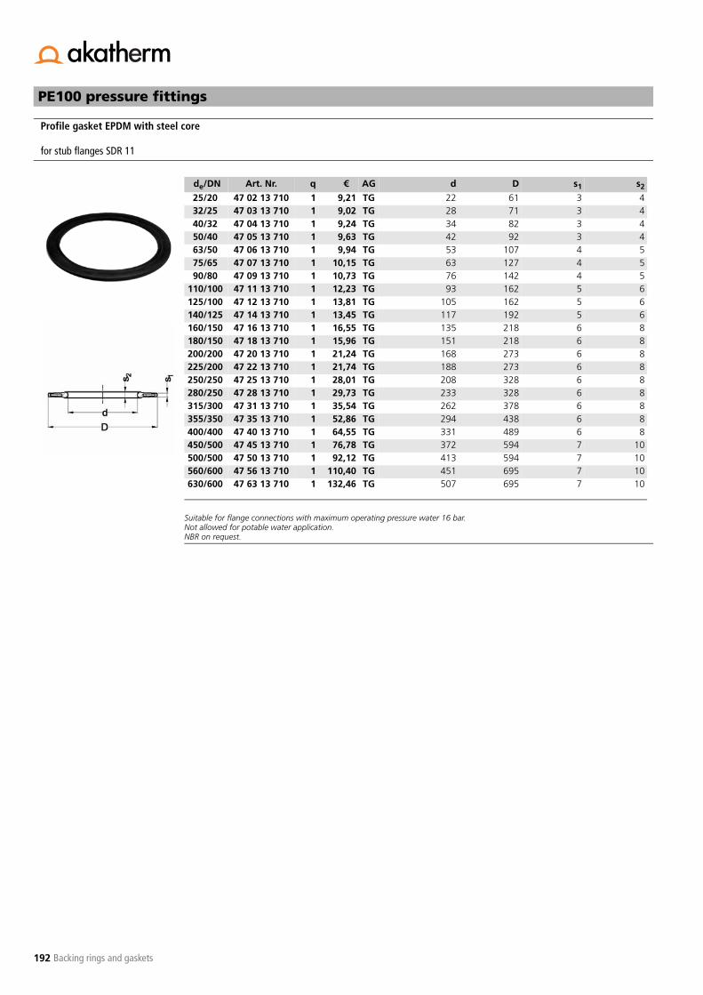
192
PE100 pressure fittings
Backing rings and gaskets
Suitable for flange connections with maximum operating pressure water 16 bar.Not allowed for potable water application.NBR on request.
Profile gasket EPDM with steel core
for stub flanges SDR 11
de/DN Art. Nr. q € AG d D s1 s2
25/20 47 02 13 710 1 9,21 TG 22 61 3 432/25 47 03 13 710 1 9,02 TG 28 71 3 440/32 47 04 13 710 1 9,24 TG 34 82 3 450/40 47 05 13 710 1 9,63 TG 42 92 3 463/50 47 06 13 710 1 9,94 TG 53 107 4 575/65 47 07 13 710 1 10,15 TG 63 127 4 590/80 47 09 13 710 1 10,73 TG 76 142 4 5
110/100 47 11 13 710 1 12,23 TG 93 162 5 6125/100 47 12 13 710 1 13,81 TG 105 162 5 6140/125 47 14 13 710 1 13,45 TG 117 192 5 6160/150 47 16 13 710 1 16,55 TG 135 218 6 8180/150 47 18 13 710 1 15,96 TG 151 218 6 8200/200 47 20 13 710 1 21,24 TG 168 273 6 8225/200 47 22 13 710 1 21,74 TG 188 273 6 8250/250 47 25 13 710 1 28,01 TG 208 328 6 8280/250 47 28 13 710 1 29,73 TG 233 328 6 8315/300 47 31 13 710 1 35,54 TG 262 378 6 8355/350 47 35 13 710 1 52,86 TG 294 438 6 8400/400 47 40 13 710 1 64,55 TG 331 489 6 8450/500 47 45 13 710 1 76,78 TG 372 594 7 10500/500 47 50 13 710 1 92,12 TG 413 594 7 10560/600 47 56 13 710 1 110,40 TG 451 695 7 10630/600 47 63 13 710 1 132,46 TG 507 695 7 10

193
PE100 pressure fittings
GOEMA pipe clips
Easy mounting of (plastic) pipe systems indoor to floor, wall or ceiling.Outdoor mounting with UV degradation restriction.1 to 3 screws for solid connection to mounting surface.Unrestricted axial pipe movement (expansion and contraction).Prevents sideward movement.Adapts radial expansion at elevated temperature.No notch effect on pipe.Colour grey RAL 7037.
Pipe clip - metric with retaining clip PP
de Art. Nr. q € AG a b h l c
16 70 00 01 200 100 0,75 PR 26 18 33 1620 70 01 01 200 100 0,83 PR 33 14 38 2025 70 02 01 200 100 0,88 PR 41 14 44 2532 70 03 01 200 100 1,10 PR 49 15 51 3240 70 04 01 200 100 1,38 PR 58 16 60 4050 70 05 01 200 100 1,58 PR 68 17 71 6063 70 06 01 200 100 1,98 PR 83 18 34 6375 70 07 01 200 100 2,96 PR 96 19 97 7590 70 09 01 200 100 3,62 PR 113 20 113 90
110 70 11 01 200 50 5,07 PR 139 23 134 125 40125 70 12 01 200 10 6,66 PR 158 25 151 140 60140 70 14 01 200 10 6,99 PR 177 27 167 155 70160 70 16 01 200 10 8,09 PR 210 30 190 180 90180 70 18 01 200 10 9,91 PR 237 33 211 200 100

194
PE100 pressure fittings
GOEMA pipe clips
Easy mounting of (plastic) pipe systems indoor to floor, wall or ceiling.Outdoor mounting with UV degradation restriction.1 to 3 screws for solid connection to mounting surface.Unrestricted axial pipe movement (expansion and contraction).Prevents sideward movement.Adapts radial expansion at elevated temperature.No notch effect on pipe.Colour grey RAL 7037.
Pipe clip - inches with retaining clip PP
de Art. Nr. q € AG a b h l c3/8" 70 77 01 200 100 0,75 PR 26 13 34 16½" 70 78 01 200 100 0,83 PR 33 14 39 20¾" 70 79 01 200 100 1,00 PR 41 14 45 251" 70 80 01 200 100 1,05 PR 49 15 52 32
1¼" 70 81 01 200 100 1,41 PR 58 16 61 401½ 70 82 01 200 100 1,58 PR 68 17 67 502" 70 83 01 200 100 1,98 PR 83 18 80 63
2½" 70 84 01 200 100 2,96 PR 96 19 96 753" 70 85 01 200 100 3,62 PR 118 20 110 904" 70 86 01 200 50 6,46 PR 140 25 135 140 606" 70 88 01 200 10 9,20 PR 197 30 196 180 90

195
PE100 pressure fittings
GOEMA pipe clips
For alignment of pipe system with FIP valves.Colour grey RAL 7037.
Distance plate for pipe clip PP
de Art. Nr. q € AG A B C D E
32 70 03 07 200 120 0,54 PR 33 16 14 8 440 70 04 07 200 80 0,72 PR 41 17 17 8 450 70 05 07 200 50 0,81 PR 51 18 17 8 463 70 06 07 200 40 0,92 PR 64 19 22,5 8 475 70 07 07 200 40 1,79 PR 76 20 34,5 8 4

196
PE100 pressure fittings
GOEMA pipe clips

197
Jointing techniques

198

199
Welding polyolefins
Welding polyolefins
9 Welding polyolefins
9.1 General
Plastic can be welded with various welding techniques, although notevery welding method is suitable for the welding of polyolefins. In desig-ning a plastic pipe system, it is therefore important to obtain informationabout possible welding techniques and their applicability as early as theplanning phase. The choice of the most appropriate welding procedure isusually influenced by following factors: economics, the construction ofthe component, external and internal influences on the system, as well aslocal conditions.
Figure 9.1 shows the welding practices most frequently used with plas-tics. The grey highlighted frames indicate the welding techniques usuallyemployed for the welding of PE in plastic pipe construction. In practice,the welding methods most frequently used to connect PE pipe compo-nents are butt-welding and electrofusion.
Figure 9.1 Welding techniques
9.2 Welding procedures
9.2.1 Socket weldingDescriptionSocket welding (also known a polyfusion) resembles butt-welding in itstechnique. The process is described in detail in the guidelines of DVS2207 Sections 1, 5 and 11 with respect to the relevant plastic being used.In socket welding, both the spigot and socket are simultaneously heated.After ending the heating process, the socket is shoved over the spigotand pressure applied. The difference from butt-welding consists in thefact that the joining surfaces are connected in an overlapping manner.Therefore, one side of the heating element possesses a form on which tomount the socket (heating spigot) and the other side a form into whichto plug the spigot (heating socket), see figure 9.2.
Figure 9.2 Socket welding
The sizes of the heating element and the elements to be welded conformto each other to the extent that the joining of the elements creates awelding pressure. Welded pipes up to a diameter of 50 mm can be wel-ded by hand, larger diameters up to and including 110 mm must be wel-ded with the aid of an apparatus.
Socket welding process - preparationIn principle, the areas corresponding to the welding seam must be care-fully prepared, as faultless quality and leak-tightness can only be guaran-teed when the joining surfaces are appropriately pre-treated. For thisreason, the following rules for preparing the welding surfaces in pipeconstruction have a great deal of importance and should always be com-plied with:- The welding surfaces are to be mechanically prepared immediately
before the welding process using a scraper, grater or peeler in orderto remove the oxidation layer.
- The spigot is to be bevelled as indicated in table 9.1. Figure 9.3 showsa properly bevelled spigot.
- The connecting surfaces of the pipes or fittings are preparedaccording to manufacture information.
- Bumping the end of the pipe against the floor of the heating tool tobe avoided.
- In welds performed without machinery, the insertion depth equal todistance (E) in table 9.1 must be marked on the pipe.
- The joining surfaces must be free of grease and dust. The socket mustbe thoroughly cleaned on the inside and the spigot on the outsideusing a degreasing agent (e.g. industrial alcohol) and absorbent,non-fraying and uncoloured paper. The same applies to the heatingelement.
- The work site should be arranged so that there are areas in whichwelding can occur independent of atmospheric conditions.
- No welding work can be performed when ambient temperatures areunder +5°C without taking special measures (e.g. protection by aheated tent). The temperature in the immediate proximity of thewelding location should not vary more than 10°C during the weldingprocedure.
- The functional capacity of the machines and equipment has to betested prior to welding. In particular, the welding parameters need tobe checked. For PE the temperature of the heating element is 250-270°C.
Hot gaswelding
Plastic welding techniques
Frictionwelding
Heated-tool welding
High-frequency welding
Ultrasonic welding
Hand welding Direct Indirect
Speed welding butt-welding Impulsewelding
Overlap welding Groovewelding
Contactwelding
Extrusion welding Fold welding Infra-redwelding
Socketwelding
Overlapwelding
Electrofusion
Wedgewelding
Bladewelding
1 Socket2 Heating spigot3 Heating socket4 Pipe5 Heating tool
Finished joint
Heating
Preparation
Welding polyolefins
200 Welding polyolefins
Table 9.1 Weld preparation phase for pipe ends
Figure 9.3 Pipe phase in socket welding
ExecutionFor heating, the pipes to be welded are to be shoved on the heating ele-ment of the device up to the mark designating the welding zone andfixed in place. The heating period specified in the data of table 9.2 thenbegins. During heating, the cross section of the pipe is to be absolutelyprevented from resting on the end of the heating socket.After completion of the heating period, the parts to be welded are to bequickly removed from the heating device and immediately pushed toge-ther without contortion up to the stopping point at the mark. In manualwelding, the joining parts must be held in place for a period specified intable 9.2. The joint may only be exposed to mechanical loads after thecooling period has ended. The heating spigot and heating socket are tobe cleaned after every welding procedure using non-fraying paper andan appropriate cleaning agent (e.g. industrial alcohol).
9.2.2 Butt-welding
Figure 9.4
DescriptionButt-welding is a very economical and reliable jointing technique in whichan additional tool is required to create the non-detachable joint. Butt-wel-ding is very well-suited to the pre-fabrication of pipe elements and theconstruction of special fittings.
It is a technique that is of great significance in the manufacture of welded fit-tings. In butt-welding, the welding surfaces (ends) of the components to bewelded are first machined (planed). This produces coplanar ends that canlater be simultaneously pressed against the heating element. The weldingsurfaces are then heated by the heating element (hot plate) and lined upunder slight pressure (alignment pressure). Subsequently, heating proceedsunder reduced pressure (heating time) and, after removing the heating ele-ment (conversion), the joint is formed under welding pressure. Diagram 9.1provides a schematic representation of the butt-welding process. Adjusta-ble heating temperatures can be varied to match wall thickness (figure 9.5).
Figure 9.5 Heating temperature as s function of PE pipe wall thickness
1 2 3 4 5
Outside pipediameter (mm)
Heating Conversation (maximum time)(s)
Cooling fixed
(s)
Cooling total
(min)
SDR 11 SDR 17
16 5 4 6 220 5 4 6 225 7 (1) 4 10 232 8 (1) 6 10 440 12 (1) 6 20 450 12 (1) 6 20 463 24 (1) 8 30 675 30 15 8 30 690 40 22 8 40 6110 50 30 10 50 8125 60 35 10 60 8
Pipe diameter Pipe phase Insertion depth
de (mm) b (mm) E (mm)16 2 1320 2 1425 2 1532 2 1740 2 1850 2 2063 3 2675 3 2990 3 32110 3 35125 3 38
(1)If wall strength is too small, welding is not advisable
Table 9.2 Standard values for socket welding of PE pipes and fittings under atmospheric tempera-ture of 20°C and moderate measurable air current (DVS 2207 Section 1)

201
Welding polyolefins
Welding polyolefins
Sign Name Entity
de nominal outside diameter of pipe mme minimum pipe wall thickness mmA bead size (end of alignment time) mm about (0.5 + 0.1 e) around evenB bead size (end of cooling time under pressure) mm minimum 3 + 0.5 e
maximum 5 + 0.75 ep1 pre-heating pressure N/mm2 0.18 +/- 0.01p2 heating pressure N/mm2 almost pressureless up to about 0.01p3 welding pressure N/mm2 0.18 +/- 0.01p4 cooling pressure N/mm2 0 (pressureless, without flexural and/or tensile stress)t1 pre-heating time s until bead size A is reachedt2 heating time s (12 +/- 1) et3 maximum conversion time s 3 + 0.01 det4 maximum built-up time s 3 + 0.03 det5 maximum welding time, under welding pressure min 3 + et6 maximum cooling time, under cooling pressure min 1.5 e
Diagram 9.1 The development of the proces of butt-welding
N/mm2
p1
p
A p3 B
p4
Butt-welding processThe execution of the butt-wel-ding process is described in'NEN 7200 Plastic piping fortransporting gas, drinkingwater and waste water - Butt-welding pipes and fittings'.ISO/TC138 has also composedworking document 'ISO/WD21307' to standardise thebutt-welding process.
t6t5
t (s)
t4t3
t2t1
p2
pipe SDR 11 pipe SDR 17
de e(SDR11) F1/F3 * A Fd ** t2 t3 t4 t5 Bmin Bmax t6 e(SDR17) F1/F3 * A Fd ** t2 t3 t4 t5 Bmin Bmax t6mm mm kN mm kN s s s min mm mm min mm kN mm kN s s s min mm mm min
32 2.9 0.05 0.8 0.003 35 3 4 6 4 7 4 1.9 0.03 0.7 0.00 23 3 4 5 4 6 340 3.7 0.08 0,9 0.004 44 3 4 7 5 8 6 2.4 0.05 0.7 0,00 29 3 4 5 4 7 450 4.6 0.12 1.0 0.01 55 4 5 8 5 8 7 3.0 0.08 0.8 0.00 36 4 5 6 5 7 563 5.8 0.19 1.1 0.01 70 4 5 9 6 9 9 3.8 0.13 0.9 0.01 46 4 5 7 5 8 675 6.8 0.26 1.2 0.01 82 4 5 10 6 10 10 4.5 0.18 1.0 0.01 54 4 5 8 5 8 790 8.2 0.38 1.3 0.02 98 4 6 11 7 11 12 5.4 0.26 1.0 0.01 65 4 6 8 6 9 8
110 10.0 0.57 1.5 0.03 120 4 6 13 8 13 15 6.6 0.39 1.2 0.02 79 4 6 10 6 10 10125 11.4 0.73 1.6 0.04 137 4 7 14 9 14 17 7.4 0.49 1.2 0.03 89 4 7 10 7 11 11140 12.7 0.91 1.8 0.05 152 4 7 16 9 15 19 8.3 0.62 1.3 0.03 100 4 7 11 7 11 12160 14.6 1.20 2.0 0.07 175 5 8 18 10 16 22 9.5 0.81 1.5 0.04 114 5 8 13 8 12 14180 16.4 1.52 2.1 0.08 197 5 8 19 11 17 25 10.7 1.02 1.6 0.06 128 5 8 14 8 13 16200 18.2 1.87 2.3 0.10 218 5 9 21 12 19 27 11.9 1.27 1.7 0.07 143 5 9 15 9 14 18225 20.5 2.37 2.6 0.13 246 5 10 24 13 20 31 13.4 1.60 1.8 0.09 161 5 10 16 10 15 20250 22.7 2.92 2.8 0.16 272 6 11 26 14 22 34 14.8 1.97 2.0 0.11 178 6 11 18 10 16 22280 25.4 3.66 3.0 0.20 305 6 11 28 16 24 38 16.6 2.47 2.2 0.14 199 6 11 20 11 17 25315 28.6 4.63 3.4 0.26 343 6 12 32 17 26 43 18.7 3.13 2.4 0.17 224 6 12 22 12 19 28355 32.2 5.88 3.7 0.33 386 7 14 35 19 29 48 21.1 3.98 2.6 0.22 253 7 14 24 14 21 32400 36.3 7.47 4.1 0.41 436 7 15 39 21 32 54 23.7 5.04 2.9 0.28 284 7 15 27 15 23 36450 40.9 9.46 4.6 0.53 491 8 17 44 23 36 61 26.7 6.39 3.2 0.36 320 8 17 30 16 25 40500 45.4 11.67 5.0 0.65 545 8 18 48 26 39 68 29.7 7.90 3.5 0.44 356 8 18 33 18 27 45560 50.6 14.58 5.6 0.81 607 9 20 54 28 43 76 33.2 9.89 3.8 0.55 398 9 20 36 20 30 50630 57.2 18.53 6.2 1.03 686 9 22 60 32 48 86 37.4 12.53 4.2 0.70 449 9 22 40 22 33 56
Clarification of process parameters
* at specific welding pressure of 0.18 N/mm2
** at specific welding pressure of 0.1 N/mm2
Table 9.3 Process parameters for butt-welding
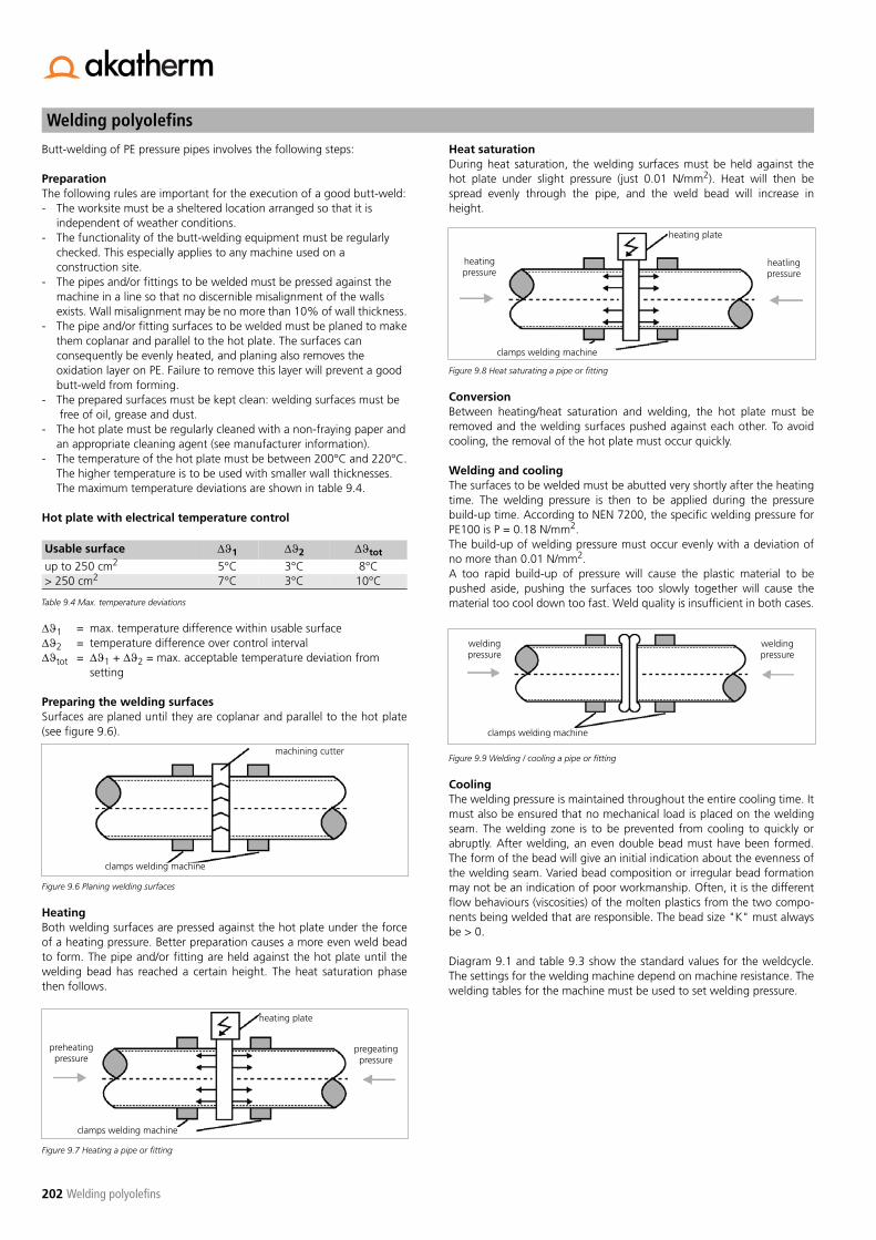
Welding polyolefins
202 Welding polyolefins
Butt-welding of PE pressure pipes involves the following steps:
PreparationThe following rules are important for the execution of a good butt-weld:- The worksite must be a sheltered location arranged so that it is
independent of weather conditions.- The functionality of the butt-welding equipment must be regularly
checked. This especially applies to any machine used on aconstruction site.
- The pipes and/or fittings to be welded must be pressed against themachine in a line so that no discernible misalignment of the wallsexists. Wall misalignment may be no more than 10% of wall thickness.
- The pipe and/or fitting surfaces to be welded must be planed to makethem coplanar and parallel to the hot plate. The surfaces canconsequently be evenly heated, and planing also removes theoxidation layer on PE. Failure to remove this layer will prevent a goodbutt-weld from forming.
- The prepared surfaces must be kept clean: welding surfaces must be free of oil, grease and dust.
- The hot plate must be regularly cleaned with a non-fraying paper andan appropriate cleaning agent (see manufacturer information).
- The temperature of the hot plate must be between 200°C and 220°C.The higher temperature is to be used with smaller wall thicknesses.The maximum temperature deviations are shown in table 9.4.
Hot plate with electrical temperature control
��1 = max. temperature difference within usable surface��2 = temperature difference over control interval��tot = ��1 + ��2 = max. acceptable temperature deviation from
setting
Preparing the welding surfacesSurfaces are planed until they are coplanar and parallel to the hot plate(see figure 9.6).
Figure 9.6 Planing welding surfaces
HeatingBoth welding surfaces are pressed against the hot plate under the forceof a heating pressure. Better preparation causes a more even weld beadto form. The pipe and/or fitting are held against the hot plate until thewelding bead has reached a certain height. The heat saturation phasethen follows.
Figure 9.7 Heating a pipe or fitting
Heat saturationDuring heat saturation, the welding surfaces must be held against thehot plate under slight pressure (just 0.01 N/mm2). Heat will then bespread evenly through the pipe, and the weld bead will increase inheight.
Figure 9.8 Heat saturating a pipe or fitting
ConversionBetween heating/heat saturation and welding, the hot plate must beremoved and the welding surfaces pushed against each other. To avoidcooling, the removal of the hot plate must occur quickly.
Welding and coolingThe surfaces to be welded must be abutted very shortly after the heatingtime. The welding pressure is then to be applied during the pressurebuild-up time. According to NEN 7200, the specific welding pressure forPE100 is P = 0.18 N/mm2.The build-up of welding pressure must occur evenly with a deviation ofno more than 0.01 N/mm2.A too rapid build-up of pressure will cause the plastic material to bepushed aside, pushing the surfaces too slowly together will cause thematerial too cool down too fast. Weld quality is insufficient in both cases.
Figure 9.9 Welding / cooling a pipe or fitting
CoolingThe welding pressure is maintained throughout the entire cooling time. Itmust also be ensured that no mechanical load is placed on the weldingseam. The welding zone is to be prevented from cooling to quickly orabruptly. After welding, an even double bead must have been formed.The form of the bead will give an initial indication about the evenness ofthe welding seam. Varied bead composition or irregular bead formationmay not be an indication of poor workmanship. Often, it is the differentflow behaviours (viscosities) of the molten plastics from the two compo-nents being welded that are responsible. The bead size "K" must alwaysbe > 0.
Diagram 9.1 and table 9.3 show the standard values for the weldcycle.The settings for the welding machine depend on machine resistance. Thewelding tables for the machine must be used to set welding pressure.
Usable surface ��1 ��2 ��tot
up to 250 cm2 5°C 3°C 8°C> 250 cm2 7°C 3°C 10°C
Table 9.4 Max. temperature deviations
machining cutter
clamps welding machine
pregeatingpressure
preheating pressure
clamps welding machine
heating plate
heating plate
heatlingpressure
heatingpressure
clamps welding machine
weldingpressure
weldingpressure
clamps welding machine

203
Welding polyolefins
Welding polyolefins
9.2.3 Electrofusion
DescriptionThe electrofusion coupling underlying the process is employed to con-nect pipe components in pressure pipe installations for gas and watersupply networks, industrial facilities and pressurised drainage systems.The process is suitable for connecting pipe components of the series:
ISO-S pipe series number / SDR- S 5 / SDR 11 (PE100)- S 8 / SDR 17 (PE100)
Figure 9.10 Electrofusion coupling
Figure 9.11 Electrofusion
Like butt-welding, electrofusion is a widespread welding technique in PEpipe construction. Applications have the following advantages:- simple procedure throughout the entire welding process- uncomplicated operation of the welding apparatus- regular quality of the welded joint due to reproducible equipment
settings- longitudinally rigid joint- mo excess or weld bead inside pipe- welding made possible for hard to access locations
Welding occurs in an overlapping form which means that the pipes and/or fittings are joined to each other through an electrofusion coupling.The resistance coil (heating coil) integrated into the electrofusion cou-pling are heated by an electrical welding unit, causing the surfaces of thepipes and the coupling (in immediate contact with the heating coil) to beplasticised. The thermal expansion of the plastic creates welding pressureso that the effects of these two parameters result in a homogeneousconnection between coupling and pipe or fitting at the end of the wel-ding time. The VM 102 guideline for welding practice applies to electro-fusion on pressure pipe installations. The guideline also makesrecommendations about quality assurance and describes possible testingmethods.
Electrofusion processThe execution of the electrofusion process is described in the weldingrecommendation 'Electrofusion sleeve welding of thermoplastics'.
Preparation- Inspect pipe and fitting for damage and proper sizing- Check state and function of welding unit- Take protective measures if weather conditions make it necessary- Pipes, fittings and welding equipment are to be kept at a constantambient temperature between -10°C and + 45°C
- Do not weld when medium is being discharged
Pretreatment1. Cut the pipe square
- slanting cuts can result in inadequate melting, overheating orburning
2. Clean the pipe3. Mark the welding zone4. Remove oxidation layer
- scrape off a long even continuous chip (min 0.15 mm thick)- an excessively thick chip will prevent the gap between coupling
and pipe from being filled- scraping 5 mm extra in width is a sign of good workmanship- filing or sanding is not permitted
5. Debur the pipe6. Make oval pipe round, be careful with pipes on cylinders and drums
- use rounding clamps if ovality >1.5% diam. or >1.5 mm
Figure 9.16 to 9.18
Cleaning1. Mark the welding zone again2. Clean the welding surface of the pipe
- welding surfaces must be absolutely clean- use PE cleaning agent and absorbent, non-fraying uncoloured
paper3. Clean inside of coupling
- take fitting out of packaging just before use- prevent rubbing contaminants from untreated surfaces from
entering the welding zone
Figure 9.12 to 9.15
Electrofusion (sleeve) coupling
Electrofusion (sleeve) coupling

Welding polyolefins
204 Welding polyolefins
Figure 9.19 and 9.20
Positioning1. Push the pipe into the fitting up to the mark2. Connect contact plugs to fitting: pay attention to tension free
assembly- shove pipe straight into coupling- do not rotate- coupling should be movable by hand
3. Guideline VM 102 prescribes: use clamps for tension-free assembly
Figure 9.21
Welding1. Scan barcode with hand reader2. Start welding process: electrofusion unit automatically regulates the
amount of energy and welding time - safe distance to welding location is 1 m
3. Compare actual with required welding time4. Note actual welding time on the pipe
- welding indicator provides an impression of the completed weld,correctness is also indicated by the welding unit
Figure 9.22 to 9.25
Cooling1. Adhere to the cooling time (CT) on the barcode before moving the
connection2. Cooling time prior to testing or operation pressure is indicated in the
tables of the FRIALEN assembly manual
9.2.4 Hot gas welding
Description- Type of weldingHot gas welding is divided into:
- hand welding- speed welding- extrusion welding
The fundamentals for individual extrusion welding techniques are provi-ded in the guidelines of DVS 2207 Sections 2, 4 and 5. The application ofhot gas welding requires special knowledge and skills from the welder.The requirements are contained in DVS 2212 Section 1.
- Functional principlesIn hot gas welding, the welding surface and filler are turned into a plasticstate by hot air and welded to each other under pressure.The heating of the air occurs in the welding tool. It must be absolutelycertain that the hot air is free of moisture, dust and oil. Hot gas weldingtechniques will be described in more detail below.
1. Hand weldingIn hot gas hand welding, the hot air is usually supplied to the elements tobe welded through a round nozzle. The filler material must be appropri-ate for the welding substrate. Mostly, the filler material used is in theform of a rod with a diameter of 3-4 mm. For welding, the rod is placedin the seam at an angle slightly off perpendicular. With a light fanningmotion, the round nozzle is pointed at the seam so that the hot airstream simultaneously heats both the rod and the substrate. By pressingdown perpendicularly on the rod, the filler is pushed along the weldingseam and, in this way, heated in the lower, curved area. A wave formsahead of the welding thread and weld beads on both sides of the seam(figure 9.27).
Figure 9.27 Hot gas hand welding
2. Speed weldingIn hot gas speed welding, the welding rod is fed through a speed-welding nozzle, heated by the hot air and pressed into the weld joint bya beaked-form tip at the bottom of the nozzle (figure 9.28).The forward movement of the nozzle is, as a rule, strong enough to drawthe welding rod through the nozzle. The welding speed of speed weldingis 3-4 times faster than that of hand welding. In contrast to hand wel-ding, this welding procedure can evenly apply the required welding pres-sure. Speed welding cannot, however, be used in positions that aredifficult to access.
1 Welding rod2 Force3 Hot air4 Round nozzle5 Welding tool6 Fanning motion7 Welding direction8 Wave9 Weld bead10 Welding seam
Figure 9.26

205
Welding polyolefins
Welding polyolefins
Figure 9.28 Speed welding
3. Extrusion weldingExtrusion welding is a partially mechanised hot-gas welding technique,primarily used to join thick-walled components. There are four variants ofextrusion welding that are used. The data about hot-gas extrusion wel-ding can be found in the guidelines contained in DVS 2207 Sections 4and 5, as well as in DVS 2209 Sections 1 and 2.
Figure 9.29 Varieties of hot gas extrusion welding
The principle machinery used in all the different variants of extrusion wel-ding is the same.
The welding equipment consists of:- Plasticising unit (extruder) for preparing the weld filler- Heating using (hot gas tool) to heat the welding surfaces- Tool to apply the required welding pressure in the form of a welding
shoe or pressure tool (figure 9.30)
Figure 9.30 Welding shoe and pressure mechanism
The form of the welding tool or pressure tool depends on the procedureand weld shape. Welding shoes are most made of PTFE (Polytetrafluo-rethylene). Hot air nozzles must be constructed in such a manner that the air isevenly distributed to the nozzle outlet and the temperature largelyremains constant.The commonest type is the hand extruder, which is constructed by designto have little weight and can therefore be operated by hand with relativeease. The extruder is made in both semi-automatic and fully automaticmodels. Extrusion welding enable various weld shapes to be made (e.g. Vseam, double V seam, fillet weld). In a continuous process, the extruderdeposits molten material (extrudate) in the weld joint, which is heated bythe hot gas. The extrudate is placed in the joint by means of the weldshoe and pressed with the required welding force, causing a homogene-ous weld to be made with the substrate surface, which has been plasti-cised by the hot gas. Very large joints require extrudate to be applied in several runs. Weldingwith the extruder requires trained and experienced professionals, as theproper advancing speed together with the necessary pressure have alarge influence on the quality of the weld. Table 9.6 shows the weldingparameters (standard values) for the individual hot-gas extrusion variants.
1 Welding rod2 Hot air3 Welding tool4 Welding direction5 Weld bead6 Welding seam7 Force8 Speed welding nozzle
Method Variant Material thickness (for single-run welding) (mm)
Temperature of molten mass (°C)
Temperature of hot air (°C)
Air flow rate(l/min)
Weld filler flow rate (kg/h)
continuousprocedure
Variant llVariant lll
Variant V
0...150...15
15...300...15
200...230200...230200...230
250...300250...250250...300
> 300> 300> 400
0...20...40...6
discontinuous procedure Variant l 0... 5 200...230 250...300 > 300 0...4
Table 9.6 Welding parameters for hot-gas extrusion welding
Varieties of hot gas extrusion welding
Variant IIContinuous procedure with hand
tool(screw)
Variant IDisconti-
nuousprocedure
withtransfer of the filler to
thepreheated
joint
Variant VContinuous procedure with hand
tool(plunger)
Variant IIIContinuous procedure with filler
transfer hose between
extruder and weld head
Welding show
1 Extrudate feed2 Recess3 Nose4 Contact surfaces5 Pressure mechanism / sliding surface
MaterialShort symbol
Type of welding Welding force (N) Round Ø 3 mm
Welding rodRound Ø 4 mm
Hot air temperature(°C)
Air quantity(l/min)
PE Hand welding 6-10 15-20 300-350 40-60PE Speed welding 10-16 25-35 300-350 40-60
Table 9.5 Welding parameters: standard values for hand and speed welding
Pressure mechanism
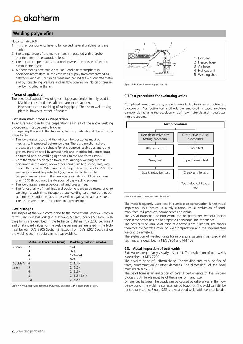
Welding polyolefins
206 Welding polyolefins
Notes to table 9.6:1 If thicker components have to be welded, several welding runs are
made.2 The temperature of the molten mass is measured with a probe
thermometer in the extrudate feed.3 The hot-air temperature is measure between the nozzle outlet and
5 mm in the nozzle.4 Air flow means here cold air at 20°C and one atmosphere in
operation-ready state. In the case of air supply from compressed airnetworks, air pressure can be measured behind the air flow rate metreand by considering pressure and air flow conversion. No oil or greasemay be included in the air.
- Areas of applicationThe described extrusion welding techniques are predominantly used in:
- Machine construction (shaft and tank manufacture).- Pipe construction (welding of casing pipes). The use to weld casing
pipes is, however, rather infrequent.
Extrusion weld process - PreparationTo ensure weld quality, the preparation, as in all of the above weldingprocedures, must be carefully done.In preparing the weld, the following list of points should therefore beattended to:- The welding surfaces and the adjacent border zones must be
mechanically prepared before welding. There are mechanical pre-process tools that are suitable for this purpose, such as scrapers andgraters. Parts affected by atmospheric and chemical influences mustbe treated prior to welding right back to the unaffected zone.
- Care therefore needs to be taken that, during a welding processperformed in the open, no weather conditions (e.g. wind, rain) mayaffect effectiveness. When ambient temperatures are under +5°C, thewelding site must be protected (e.g. by a heated tent). Thetemperature variation in the immediate vicinity should be no morethan 10°C throughout the duration of the welding process.
- The welding zone must be dust, oil and grease free.- The functionality of machines and equipment are to be tested prior to
welding. At such time, the appropriate welding parameters are to beset and the standard values to be verified against the actual values.The results are to be documented in a test record.
- Weld shapesThe shapes of the weld correspond to the conventional and well-knownforms used in metalwork (e.g. filet weld, V seam, double V seam). Wel-ding forms are described in the technical bulletins DVS 2205 Sections 3and 5. Standard values for the welding parameters are listed in the tech-nical bulletin DVS 2205 Section 3. Except from DVS 2207 Section 3 onthe welding seam structure in hot gas welding.
Figure 9.31 Extrusion welding (Variant III)
9.3 Test procedures for evaluating welds
Completed components are, as a rule, only tested by non-destructive testprocedures. Destructive test methods are employed in cases involvingdamage claims or in the development of new materials and manufactu-ring procedures.
Figure 9.32 Test procedures used for plastic
The most frequently used test in plastic pipe construction is the visualinspection. This involves a purely external visual evaluation of semi-manufactured products, components and welds. The visual inspection of butt-welds can be performed without specialtools if the tester has the appropriate knowledge and experience.The possibility of visual evaluation of electrofusions is limited. The checkstherefore concentrate more on weld preparation and the implementedwelding parameters.The evaluation of welded joints for in pressure systems most used weldtechniques is described in NEN 7200 and VM 102.
9.3.1 Visual inspection of butt-weldsButt-welds are primarily visually inspected. The evaluation of butt-weldsis described in NEN 7200.The bead must be of uniform shape. The welding area must be free oftears, contamination or other damages. The dimensions of the beadmust mach table 9.3.The bead form is an indication of careful performance of the weldingprocess. Both beads must be of the same form and size.Differences between the beads can be caused by differences in the flowbehaviour of the welding surfaces joined together. The weld can still befunctionally sound. Figure 9.33 shows a good weld with identical beads.
Material thickness (mm) Welding rod x diameter
V seam 2345
1x43x31x3+2x46x3
Double V seam
456810
2 (1x4)2 (3x3)2 (3x3)2 (1x3+2x4)2 (6x3)
Table 9.7 Weld shape as a function of material thickness with a cone angle of 60°C
1 Extruder2 Heated hose3 Air hose4 Hot gas unit5 Welding shoe
Test procedures
Non-destructive-freetesting procedure
Destructive testingprocedures
Ultrasonic test Tensile test
X-ray test Impact tensile test
Spark induction test Creep tensile test
Technological flexualtest
1 2 3
4
5

207
Welding polyolefins
Welding polyolefins
Figure 9.33 Butt-weld with identical welding beads (good)
Misalignment of the two ends can have various causes. Uneven narro-wing of one of the ends or ovality are two of the possibilities. As long asthe difference is smaller that 10% of the pipe / fitting wall thickness, theweld can be regarded as "acceptable" (see figure 9.34).
Figure 9.34 Butt-welding with acceptable wall misalignment
Too high heat or too strong pressure causes the beads to be too large.Figure 9.35 shows that the uniformity of the two beads makes this weldstill "acceptable".
Figure 9.35 Butt-weld with welding beads that are too large but still acceptable.
Figure 9.36 represents a weld with beads that are too small, suggestingthat the heating was too low and/or pressure too weak. In thick walledpipes, undersized beads are often associated with the formation of shrink-age cavities. These sorts of welds must be deemed "unacceptable".
Figure 9.36 Unacceptable butt-weld
Figure 9.37 provides a cross-sectional view of a good weld. The bead isround, notch-free and with a misalignment of max. 0.1 e. Bead size "K"must be at least equal to wall thickness e.
Figure 9.37 Cross-section of a good weld
9.3.2 Visual inspection of electrofusion jointsAn indication of weld quality based on the bead form in butt-welding cannotbe similarly obtained in electrofusion. Any opportunity to test the plastici-sation and associated weld between electrofusion sleeve and the corres-ponding components to be welded can only occur on the basis of thechanged indicators found on the coupling. If they do not provide any clearview of the quality of the weld and if the joint is not to be destroyed, one ofthe non-destructive testing procedures must be employed (e.g. ultrasound,X-rays). These are generally expensive and to inaccurate for evaluating theweld quality. In visually inspecting the weld, it must be absolutely certain thatthere are no discernible visible traces (e.g. scratches, tarnished surfaces, sco-ring in the immediate area of the coupling) relating to the mechanical pro-cedures required for faultless weld quality.
The following description about evaluating electrofusions is a copy fromNIL weld practice guideline VM102:
An electrofusion weld is of good quality when the weld has sufficientmechanical strength over the long term, and the welding zone is homoge-neous and free of cracks, contaminants and holes. In addition, verificationmust be made of the correct welding and cooling times used in the process.For proper quality control, it is also necessary to make a few trial welds priorto the production welding. These are performed under controlled work-site conditions using the applicable type of material and accurately obser-ving the welding conditions (welding and cooling times). A few of thesewelds are to be subjected to destructive analysis:- on the basis of a tensile test- on the basis of a detachment test
The test welds can be further used as reference material for visual inspecti-ons of the actual welds.
All joints welded with deviant parameters or in which the welding does notmeet stated requirements concerning their execution are to be removed.
�
�
�
�

Welding polyolefins
208 Welding polyolefins
Visual inspectionApart from the sample destructive testing, an accurate visual inspection isof crucial importance, together with the establishment of welding parame-ters. The appearance of the actual welds must be scrupulously examinedand compared to the reference welds. No large deviations from the refe-rence welds may occur.
No scratches, impurities or other damage may appear in the welding zone.
Attention also has to be paid to:- proper insertion depth of the pipe in the fitting.- alignment of the various components in the pipe system.- deviation from the straight position of the pipe in the coupling.
No more that 1 mm deviation may be measured over a distance of 300 mm from the socket (angle of deviation < 0.2°).
- resistance coil is imperceptible.- regular filling of the original gap between coupling and pipe.- heat damage.- bonding flaws due to bent pipes or insufficient shape-retention of
saddles.- the ovality of the pipe in the coupling. After welding, this may not be
more that 1.5% of the average outside diameter of the pipe, with amaximum of 1.5 mm.
- the presence of welding indicators, if any.
Figure 9.38
Figure 9.39
9.3.3 Testing joints produced by hot gas weldingUltrasonic and spark induction tests are two non-destructive testing pro-cedures that have proven use for machine construction in which hot gasextrusion welding is predominantly used. However, a simple visualinspection of the weld is often helpful in many cases. Relatively accuraterecognition and location of flaws inside of a welded joint requires testingby means of ultrasound. These days, there are appropriately constructedsenders and receivers for individual weld forms with which an experi-enced ultrasonic tester can recognise and properly interpret the smallestdefect in the weld. Well-trained personnel having appropriate experiencewith this test method are, however, an absolute necessity, which makesthe costs of such a test significantly high. In contrast, the spark inductiontest is substantially less expensive and simple to perform.
OvalityAngle deviation
300
pipeFitting
Heat damage Insufficient retention of shape
x
x x
x
Insufficient retention of shape
Insufficient retention of shape
Bent or coiling pip
PipeFitting
PipeFitting
OvalityPoor weld preparation
Insufficient insertionImproper clamping
Inadequate fusionIrregular shape of pipeor coupling
AxialRadial
Shifted resistance coil
A A
Contamination
Cross section A-A
Insufficient retention of shape

209
Welding polyolefins
Welding polyolefins
9.4 Chapter summary
PE welding Welding is for plastic pipe systems and equipment construction a common jointing technique. PE pipe systems are prominently jointed by butt-welding and electrofusion methode.
Butt-welding equipment The principle pieces of butt-welding equipment are: plane (in pipe construction machines), hot plate, clamping tool and hydraulic unit. Construction site (portable, e.g. trench welding machines) and workshop machinery (stationary welding machines) may be used. Construction-site machines are increasingly being converted to CNC controlled machines (fully automatic), which enable the construction-site operation to ensure reproducibility of welding joints and the automatic production of reports.
Bead formation in butt-welding Visual inspection of the form in which the bead is created can provide an indication of weld quality. However, such evaluation requires sound, appropriate, practical and theoretical expertise about the welding process.
Electrofusion Electrofusion is a practice also known as electric "sleeve" or "saddle" welding. The joining of the welding mates is effected by an electrofusion coupling on the inside of which an integrated heating coil (electrical resistance coil) is charged with current during the welding process and is heated as a result of its electrical resistance. As a conse-quence, the surfaces of both the coupling and the pipe or fitting (i.e. the contact areas) are plastcised. The process creates a homogeneous joint between electrofusion coupling and pipe/fitting.
Hot gas welding techniques Hot gas welding is distinguished into hand welding, speed welding and extrusion welding. The plasticisation of the welding zones occurs by heating the welding surfaces (and filler material) with hot air. For this purpose, hot air is forced through a nozzle shaped specifically to sufficiently heat and plasticise the joint surfaces.
Hand welding The welding tool in which the appropriate nozzle is mounted (in most cases a round nozzle) is moved in a fanning motion over the surfaces to be welded. In this way, the substrate and welding filler are heated until the material in the welding zone is placticised. The filler (mostly in the form of a rod) is perpendicularly pressed by hand into the welding zone. The necessary welding or joining pressure is applied by pushing down the welding rod by hand during the welding process. Appropriate welder skills and abilities are therefore required.
Speed welding The heating of the substrate and filler occurs by means of the beak-shaped tip at the lower end of the speed-wel-ding nozzle. The necessary welding pressure is applied by this nozzle.
Extrusion welding Four different variants of extrusion welding are used. The individual variants are different in terms of material supply, type of welding equipment (e.g. hand extruder) and pressure tool (e.g. plunger, welding shoe). An extrusion wel-ding extruder generally has the following elements: plasticising unit, hot gas tool and device for applying the required welding pressure.
Welding shoe / pressure tool A welding shoe or pressure tool has an effect on the appearance, formal possibilities and quality of the weld. This equipment is manufactured and adjusted in accordance with the desired seam width and form. The welding shoe has the function of evenly distributing the molten material produced in extrusion into the joint and applying the appropriate welding pressure.
Tools used in extrusion welding Work performed in extrusion welding makes use of a hand or stationary extruder with swivel head and transfer hose.
Weld preparation Weld preparation is extremely important in all welding procedures. It has a significant effect on the quality of the weld and should therefore be undertaken with utmost care.
Testing welds A distinction is made between destructive and non-destructive tests. Destructive test methods are chiefly used to evaluate cases involving damage claims.
Evaluating welded joints Visual inspection is a non-destructive method of evaluating welds frequently employed in practice. This evaluation is primarily concerned with appearance (e.g. welding bead of butt-welding). It is however a type of assessment requi-ring theoretical and practical knowledge, as well as appropriate tester experience. If more accurate indications of weld quality are needed, then a more expensive non-destructive (e.g. ultrasonic or X-ray test) or destructive testing method has to be adopted.

Welding polyolefins
210 Welding polyolefins

211
Quality
Quality
10 Quality
10.1 Production quality
The Management System of Akatherm BV has been approved:- ISO 9001 for the Quality Management System- ISO 14001 for the Environmental Management SystemThis concerns the development, manufacturing, marketing and supply ofplastic pipe systems.
PE100 pressure fittings are manufactured generally in accordance withthe following standards:
PE100 pressure fittings are subjected to the following mechanical pro-duct tests:- Hydraulic test 20°C/100h EN921- Hydraulic test 80°C/165h EN921- Hydraulic test 80°C/1000h EN921- Decohesive resistance test A ISO13954/ISO13955, for electrofusion
fittings- Decohesive resistance test B ISO13956, for electrofusion saddles- Tensile strength ISO13953, for butt-fusion- Impact resistance test EN1716, for electrofusion saddles- Pressure drop test EN12117, for electrofusion saddles
10.2 Quality inspection during work-site assembly
Quality inspections during assembly are key to the manufacture of a reli-able pipe system. Assembly has to be performed according the appicablestandards and guidelines and the user needs to exercise constant careregarding quality assurance issues.Instructions for quality-assurance measures during assembly work:- Prior to assembly, check pipes and pipe components for flawless
appearance and workmanship.- Make sure that fittings and especially flange connections are
incorporated in a stress-free manner.- Check the brackets to ensure that linear or point loads cannot occur.- Examine the construction of the brackets and fixed points. Are they
stable or somewhat undersized?- Have inappropriate compulsory guides for the pipe replaced.- Can the pipe system expand without hindrance? If so, are the fixed
points, sliding brackets and guide brackets (sliding and guide saddles)placed in the right locations?
- Is the movement of the pipe so large that it can easily begin to swing?In such case, additional guide brackets (guide saddles) are to beincorporated.
- Has care been taken to ensure that connections to pumps and tanksare elastic enough to enable longitudinal and transverse movementwithout large reaction forces?
- Place high value on strict adherence to welding regulations and have arecord made of each seam.
The preceding abstract should encourage critical monitoring and correctionof assembly work.
10.3 Leak test prior to initial use
Prior to initial use, pipe systems must be tested for strength and leak-tightness in order to demonstrate that they are leak-proof and suffi-ciently robust to withstand the mechanical load.
The goal of the pressure test is to subject the completely installed pipesystem to loading above the operation load and therefore to perform anempirical demonstration of its reliability. Any existing leakage in flangeconnections can be promptly remedied and the effects of expansion pro-cesses under internal pressure and temperature changes observed.However, small defects in the pipe system may remain undetected. Onlyin the rarest cases do these result in failure of the pipe system in the ope-rating state. As a result, the pressure test is a means of verifying the over-all quality-control concept.
Leak test according to DIN 4279-1DIN 4279-1 part 1 "Leak test of pressure pipe systems for water" containsguidelines for accomplishing the leak test. In DVS 2210-1 complementaryguidelines for aboveground pressure systems are described. After running the pressure test, the characteristics of plastic pipes resultin an increase in the pipe's internal volume. At the same time, filling thepipe system with cold water causes, in most cases, a temperature changein the pipe wall. For instance, a temperature change in the pipe wall of10°C during the pressure test will lead to a pressure decrease of 0.5 to 1bar, even though the pipe network is absolutely sealed. This behaviour istaken into account by dividing the pressure test into two parts.
1. Pre-test stageThe pre-test is intended to eliminate volume change in order to enable aclear conclusion about the leak-tightness of the system to be drawn inthe main test.
2. Main test stageEven during the main test, consideration needs to be given to the factthat expansion processes are continuing, if only to a limited degree. To becertain, it is recommended not to begin the main test for 2 hours afterterminating the pre-test.
Short term testPipes up to DN 50 and a total length of 100 m can be subjected to ashort-term test. The short-term test represents a special case, as it is notvery efficient in exposing deficiencies in the pipe system.
Standard Title
EN 12201:2003 Plastics piping systems for water supply - Polyethylene (PE)Part 3: Fittings
EN 1555:2002 Plastics piping systems for the supply of gaseous fuels - Polyethylene (PE)Part 3: Fittings
EN 13244:2003 Plastics piping systems for buried and aboveground pressure systems for water for general purposes, drainage and sewerage - Polyethylene (PE)Part 3: Fittings
DIN 16963 Pipe joints and components of Polyethylene (PE) for pipes under pressure
ISO 15494:2003 Plastics piping systems for Industrial applications-Polybutene (PB) Polyethylene (PE) Polypropylene (PP)
Table 10.1

Quality
212 Quality
PE pipe systems Pre test Main test Short term test
Test pressure (*) 1,5 * PN max (PN + 5) bar 1,3 * PN max (PN + 3) bar 1,5 * PNLength of the test min. 3 hours for pipe systems without
branches with a total length < 100 m
min. 6 hours for pipe systems with branches with a total length > 100 m
min. 3 hours for pipe systems without branches with a total length < 100 m
min. 6 hours for pipe systems with branches with a total length > 100 m
min. 1 hours for pipe systems withoutbranches with a total length < 100 m
min. 3 hours for pipe systems with branches with a total length > 100 m
Check during test Every hour with recovery of test pres-sure
Every 1.5 hour with recovery of test pressure
Every hour with recovery of test pressure
Material specificpressure drop (direction)
< 0,8 bar / h < 0,3 bar / h < 0,8 bar / h
Direction for test Normal Normal Exceptional case (approval of client required)
Table 10.2 Recommended test for installed pressure pipe systems
(*) The test pressure depends on the maximum operating pressure for the pipe series (SDR). Thetest pressure has to be selected in a way no damage will be caused to the pipe system. Also thereduced pressure load of fittings has to be taken into account. During the test connections haveto be accessible. Complementary details can be found in DIN 4279 Part 1.
10.4 Chapter summary
General quality controls In connection with general quality controls, relevant tests should be run to ensure the quality and functionality of the employed fittings as well as the factory-made or on-site manufactured pipe systems. Such tests are best served by non-des-tructive test procedures.
Pressure test The pressure test is only used for pressure pipe systems. It verifies both internal pressure stability and the leak-tightness of the system. Pressure tests consist of two test stages: the pre-test and the main test. In exceptional cases, a short-term test can be urn on pipe systems in which de < 50 mm and pipe length is a max. 100 m.

213
Appendices

214

215
Appendix A - General Diagrams
Appendix A
Appendix A - General Diagrams
A-1 Reference stress for PE100N
ote:
Th
e re
fere
nce
stre
ss
repr
esen
ts
the
mec
hani
cal
stre
ngth
of
pl
astic
pi
pes.
The
refe
renc
e st
ress
is u
sed
to c
alcu
late
mec
hani
cal
stre
ngth
usi
ng t
he e
quat
i-on
s sh
own
in s
ectio
ns 7
.2.4
to
7.2.
9.
Sour
ce: D
VS
2205
-1
Serv
ice
life
t LD
Reference stress �ref (N/mm2)
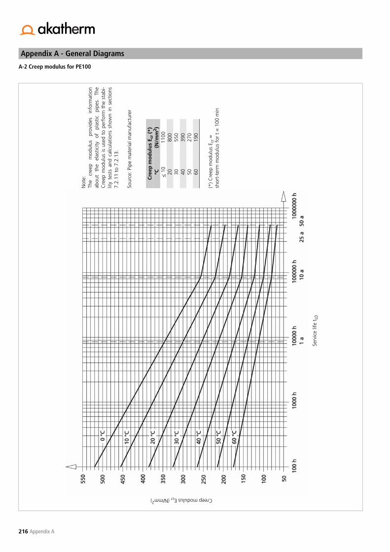
Appendix A - General Diagrams
216 Appendix A
A-2 Creep modulus for PE100
Not
e:
The
cree
p m
odul
us
prov
ides
in
form
atio
nab
out
the
elas
ticity
of
pl
astic
pi
pes.
Th
eC
reep
mod
ulus
is u
sed
to p
erfo
rm t
he s
tabi
-lit
y te
sts
and
calc
ulat
ions
sho
wn
in s
ectio
ns7.
2.11
to
7.2.
13.
Sour
ce: P
ipe
mat
eria
l man
ufac
ture
r
(*) C
reep
mod
ulus
Ecr
=sh
ort-
term
mod
ulus
for
t =
100
min
Cre
ep m
od
ulu
s E c
r (*
)ºC
(N/m
m2 )
< 1
011
0020
800
3055
040
390
5027
060
190
Serv
ice
life
t LD
Creep modulus Ecr (N/mm2)

217
Appendix A - General Diagrams
Appendix A
A-3 Friction values for plastic pipes (according to Moody)
Reyn
olds
num
ber
Re
Pipe friction factor
Lam
inar
flo
wTu
rbul
ent
flow

Appendix A - General Diagrams
218 Appendix A
a=
Pipe
bed
ding
(Pip
e zo
ne)
100
mm
in c
ase
of n
orm
algr
ound
prop
ortio
ns15
0 m
m in
cas
e of
sto
ne o
r st
ony
grou
ndb
=Pi
pe z
one
with
cov
er h
eigh
t H
cc
=Tr
ench
fill
ing
with
a c
over
hei
ght
abov
epi
pe z
one
of m
in 8
00 m
m
(
ston
e fr
ee s
and,
com
pact
ed)
Are
a of
val
idity
:Pi
pes
with
SD
R 33
/ PN
5
Tren
ch w
idth
Tren
ch f
illin
gw
ith c
ompa
ctab
le g
roun
d
Cov
er a
ngle
> 9
0o
Cover height h
A-4 Acceptable load of underground pipes of PE100 (SDR 33): Proctor density Dpr = 90%, gradient angle ß = 60º
Cover height h (mm)
Tem
pera
ture
of
the
pipe
wal
l Tw
(o C)
Hc

219
Appendix A - General Diagrams
Appendix A
Are
a of
val
idity
:Pi
pes
with
SD
R 33
/ PN
5
Cover height h (mm)
Tem
pera
ture
of
the
pipe
wal
l Tw
(o C)
A-5 Acceptable load of underground pipes of PE100 (SDR 33): Proctor density Dpr = 95%, gradient angle ß = 60º
a=
Pipe
bed
ding
(Pip
e zo
ne)
100
mm
in c
ase
of n
orm
algr
ound
prop
ortio
ns15
0 m
m in
cas
e of
sto
ne o
r st
ony
grou
ndb
=Pi
pe z
one
with
cov
er h
eigh
t H
cc
=Tr
ench
fill
ing
with
a c
over
hei
ght
abov
epi
pe z
one
of m
in 8
00 m
m
(
ston
e fr
ee s
and,
com
pact
ed)
Tren
ch w
idth
Cov
er a
ngle
> 9
0o
Cover height h
Hc
Tren
ch f
illin
gw
ith c
ompa
ctab
le g
roun
d

Appendix A - General Diagrams
220 Appendix A
Are
a of
val
idity
Pipe
s w
ith S
DR
33 /
PN 5
Tren
ch w
idth
Tren
ch fi
lling
with
com
pact
able
gro
und
Cov
er a
ngle
> 9
0o
Cover height h
A-6 Acceptable load of underground pipes of PE100 (SDR 33): Proctor density Dpr = 90%, gradient angle ß = 90º
Cover height h (mm)
Tem
pera
ture
of
the
pipe
wal
l Tw
(o C)
a=
Pipe
bed
ding
(Pip
e zo
ne)
100
mm
in c
ase
of n
orm
algr
ound
prop
ortio
ns15
0 m
m in
cas
e of
sto
ne o
r st
ony
grou
ndb
=Pi
pe z
one
with
cov
er h
eigh
t H
cc
=Tr
ench
fill
ing
with
a c
over
hei
ght
abov
epi
pe z
one
of m
in 8
00 m
m
(
ston
e fr
ee s
and,
com
pact
ed)
Hc

221
Appendix A - General Diagrams
Appendix A
A-7 Acceptable load of underground pipes of PE100 (SDR 33): Proctor density Dpr = 95%, gradient angle ß = 90º
Are
a of
val
idity
Pipe
s w
ith S
DR
33 /
PN 5
Tren
ch w
idth
Tren
ch fi
lling
with
com
pact
able
gro
und
Cov
er a
ngle
> 9
0o
Cover height h
Cover height h (mm)
Tem
pera
ture
of
the
pipe
wal
l Tw
(o C)
a=
Pipe
bed
ding
(Pip
e zo
ne)
100
mm
in c
ase
of n
orm
algr
ound
prop
ortio
ns15
0 m
m in
cas
e of
sto
ne o
r st
ony
grou
ndb
=Pi
pe z
one
with
cov
er h
eigh
t H
cc
=Tr
ench
fill
ing
with
a c
over
hei
ght
abov
epi
pe z
one
of m
in 8
00 m
m
(
ston
e fr
ee s
and,
com
pact
ed)
Hc

Appendix A - General Diagrams
222 Appendix A
A-8 Acceptable load distances for sliding brackets
Wall distance WD (mm)
Acc
epta
ble
load
dis
tanc
e L B
(m)
Acc
LB
< a
cc L
D
Plug
M8
Brac
ket
with
ligh
t en
d pl
ate
WD
B D =
WD +
(de/
2)
BD

223
Appendix A - General Diagrams
Appendix A
A-9 Acceptable load distances for sliding brackets
Wall distance WD (mm)
Acc
epta
ble
load
dis
tanc
e L B
(m)
Acc
LB
Plug
M8
Brac
ket
with
ligh
t en
d pl
ate
WD
B D =
WD +
(de/
2)
< a
cc L
D
BD

Appendix A - General Diagrams
224 Appendix A
A-10 Acceptable load distances for sliding brackets
Wall distance WD (mm)
Acc
epta
ble
load
dis
tanc
e L B
(m)
Acc
LB
< a
cc L
D
Plug
M8
Brac
ket
with
ligh
t en
d pl
ate
WD
B D =
WD +
(de/
2)
BD
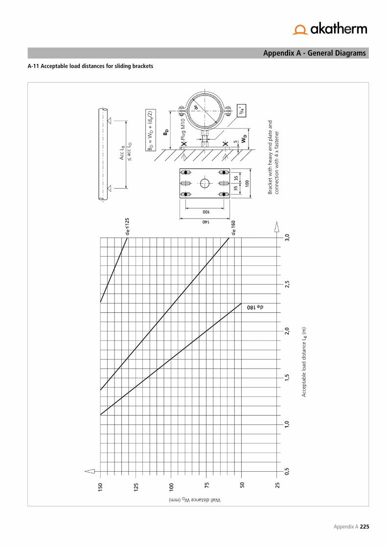
225
Appendix A - General Diagrams
Appendix A
A-11 Acceptable load distances for sliding brackets
Wall distance WD (mm)
Plug
M10
Acc
epta
ble
load
dis
tanc
e L B
(m)
Brac
ket
with
hea
vy e
nd p
late
and
conn
ectio
n w
ith 4
x f
aste
ner
Acc
LB
< a
cc L
D
B D =
WD +
(d
e/2)
WDB
D

Appendix A - General Diagrams
226 Appendix A
B D =
WD +
(d
e/2)
A-12 Acceptable load distances for sliding brackets
Wall distance WD (mm)
Acc
epta
ble
load
dis
tanc
e L B
(m)
Plug
M10
Brac
ket
with
hea
vy e
nd p
late
and
conn
ectio
n w
ith 4
x f
aste
ner
Acc
LB
< a
cc L
D
WDB
D

227
Appendix A - General Diagrams
Appendix A
A-13 Acceptable load distances for sliding brackets
Wall distance WD (mm)
Acc
epta
ble
load
dis
tanc
e L B
(m)
Plug
M10
Brac
ket
with
hea
vy e
nd p
late
and
conn
ectio
n w
ith 4
x f
aste
ner
Acc
LB
< a
cc L
D B D =
WD +
(de/
2)
WDB
D

Appendix A - General Diagrams
228 Appendix A
A-14 Acceptable load distances for fixed-point brackets
Bracket distance BD (mm)
Acc
epta
ble
F B
Plug
M8
Brac
ket
with
ligh
t en
d pl
ate
F B
F B
BD

229
Appendix A - General Diagrams
Appendix A
A-15 Acceptable load distances for fixed-point brackets
Bracket distance BD (mm)
Acc
epta
ble
F B
Plug
M10
Brac
ket
with
ligh
t en
d pl
ate
F B
F B
BD

Appendix A - General Diagrams
230 Appendix A
A-16 Flow nomogram for pressure PE100 pipe system in the SDRseries 17 and 11
Table A16b and A16c indicate the range of applications (flow rate limits:minimum and maximum flow rate for individual pipe diameters) withinwhich certain pipes of the PE100: SDR series 17 and 11 can be used (accor-ding to the pressure loss tables for PVC-U, PE-HD and PE-LD pressure pipesfrom the German Plastic Pipe Association). The areas of validity for the listed flow-rate values correspond to tap waterpipes as specified in DVGW W 302 with a flow-medium temperature(water) of 10°C. These values are used in the calculation because they usu-ally form the basis of a tap water system. For deviating operating tempera-tures, the read values for pressure loss at a corresponding flow-rate amountare to be multiplied by the correction factor from table A16a. Intermediaryvalues are to be interpolated or read directly from the pressure loss tablesfrom KRV. The use of the flow nomogram (diagram A16) is illustrated by asmall application example in the diagram. The broken lines indicate theupper and lower limits of the respective pipe dimensions. Given the pipedimensions 110 x 10 mm (SDR 11), the corresponding values are read fromthe flow nomogram. To clarify the application limits of our example, theupper and lower boundaries of the flow capacity are shown as broken lines.
For instance, the selected pipe dimension de = 110x10 mm, inside diameterds = 90 mm and flow-rate volume (V) = 5 l/s produces a flow velocity (w) 0,8 m/s and a pressure loss (�p) of 0,7 bar/100 m.
Table A16a Correction factors for the determination of pressure loss with corresponding pipe dimensions
.
~~~~
Operating temperature (TO)(°C)
Correction factor( - )
0 1.0710 1.0020 0.9630 0.9240 0.8950 0.8760 0.85
Exact values see: DVGW Process Sheet W 302 Pressure tables from the RKV
Insidediameterplastic pipe
Water amount Flow velocity Pressure loss per 100 mplastic pipe
Minimum value
Maximum value
Subject to changes
.
Sample reading
Diagram A16

231
Appendix A - General Diagrams
Appendix A
Table A16b Replacement ranges of SDR 17 pipes in terms of flow-rate capacity (min. and max. flow rate)
i
i
i
i
i
i
i
i
i
i
i
i
i
i
i
i
i
i
i
i
i
i
i
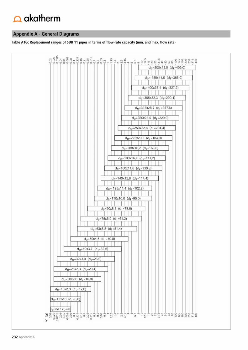
Appendix A - General Diagrams
232 Appendix A
Table A16c Replacement ranges of SDR 11 pipes in terms of flow-rate capacity (min. and max. flow rate)
i
i
i
i
i
i
i
i
i
i
i
i
i
i
i
i
i
i
i
i
i
i
i
i
i
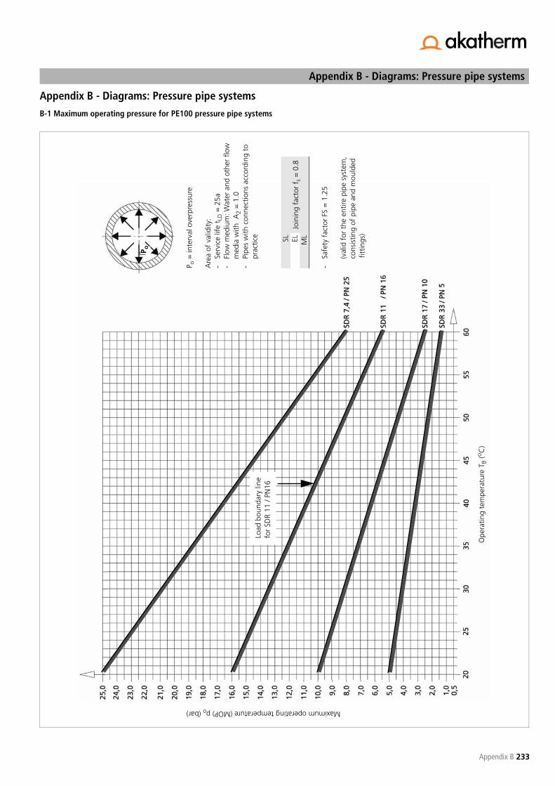
233
Appendix B - Diagrams: Pressure pipe systems
Appendix B
Appendix B - Diagrams: Pressure pipe systems
B-1 Maximum operating pressure for PE100 pressure pipe systems
Maximum operating temperature (MOP) po (bar)
Ope
ratin
g te
mpe
ratu
re T
B (o C
)
P o =
inte
rval
ove
rpre
ssur
e
Are
a of
val
idity
:-
Serv
ice
life
t LD =
25a
-Fl
ow m
ediu
m: W
ater
and
oth
er f
low
med
ia w
ith A
2 =
1.0
-Pi
pes
with
con
nect
ions
acc
ordi
ng t
opr
actic
e
-Sa
fety
fac
tor
FS =
1.2
5
(val
id f
or t
he e
ntire
pip
e sy
stem
, co
nsis
ting
of p
ipe
and
mou
lded
f
ittin
gs)
SLJo
inin
g fa
ctor
fs
= 0
.8EL ML
Load
bou
ndar
y lin
e fo
r SD
R 11
/ PN
16
P o

Appendix B - Diagrams: Pressure pipe systems
234 Appendix B
B-2 Maximum operating pressure for pipes and fittings of PE100 / SF = 1.25
MO
P (b
ar)
MO
P (b
ar)
MO
P (b
ar)
Tw (°C)Tw (°C)
Tw (°C)
PE100/SDR11
PE100/SDR33
PE100/SDR17
The indicated values do not apply to pipes exposed to UV radiation.Maximum operating pressures of <1 are not included in the tables. ForSiphonic Roof Drainage and Soil & Waste Systems, see the TechnicalManual and pricelist for Akatherm Specialist Drainage Systems.
1 = pipe, injection fittings, seamless bends and welded bends = 30°
2 = welded bends >30°- 90°, tees 90° welded
3 = welded 60° tees
4 = welded 45° tees
SF = safety factor 1.25tld = lifespan 25aMOP = internal pressureTw (°C) = pipe wall temperature

235
Appendix B - Diagrams: Pressure pipe systems
Appendix B
B-3 Thermal length change in PE100 pipe systems
Ther
mal
ly c
ondi
tione
d le
ngth
cha
nge �
l � (m
m)
Temperature difference �� (K)
Line
ar e
xpan
sion
coe
ffic
ient
for
PE1
00�� =
0.1
8 m
m /
(m K
)
�� =
Ave
rage
line
ar e
xpan
sion
coe
ffic
ient
Pipe
leng
th L
(m)

Appendix B - Diagrams: Pressure pipe systems
236 Appendix B
B-4 Acceptable support distance for water-filled PE100 pipes according to DVS guideline 2210 P1
Brac
ket
dist
ance
LD (m
m)
Operating temperature TB (°C)
Om
reke
ning
sfac
tore
n f 1
:
Are
a of
val
idity
:In
stal
latio
n te
mpe
ratu
reT M
= 2
0ºC
Life
span
t LD =
25
year
s
PE10
0SD
R 1
7SD
R 1
1PN
10
PN 1
60.
911.
00
Brac
ket
dist
ance
LD (m
m)

237
Appendix B - Diagrams: Pressure pipe systems
Appendix B
B-5 L-expansion bends
Expa
nsio
n be
nd le
ngth
LB2
(mm
)
System length total L1 (mm)
FP=
fix
ed p
oint
sG
B =
gui
de b
rack
etd e
=
pip
e ou
tsid
e di
amet
er
Mat
eria
l: PE
100
Are
a of
val
idity
:In
stal
latio
n te
mpe
ratu
re T
I = 2
0ºC
Ope
ratin
g te
mpe
ratu
re T
O =
up
to 3
0ºC
SDR
17/1
1
Tota
l L1
FPG
B
FP

Appendix B - Diagrams: Pressure pipe systems
238 Appendix B
B-6 L-expansion bends
Expa
nsio
n be
nd le
ngth
LB2
(mm
)
System length total L1 (mm)
FP=
fix
ed p
oint
sG
B =
gui
de b
rack
etd e
=
pip
e ou
tsid
e di
amet
er
Mat
eria
l: PE
100
Are
a of
val
idity
:In
stal
latio
n te
mpe
ratu
re T
I=
20º
CO
pera
ting
tem
pera
ture
TO
= u
p to
30º
CSD
R 17
/11
Tota
l L1
FPG
B
FP

239
Appendix B - Diagrams: Pressure pipe systems
Appendix B
B-7 U-expansion bends
Expa
nsio
n be
nd le
ngth
LB2
(mm
)
System length total L0 (mm)
FP=
fix
ed p
oint
sG
B =
gui
de b
rack
etd e
=
pip
e ou
tsid
e di
amet
er
Mat
eria
l: PE
100
Are
a of
val
idity
:In
stal
latio
n te
mpe
ratu
re T
H =
20º
CO
pera
ting
tem
pera
ture
TO
= 2
0 to
45º
C
Pip
e-d
eL u
d e 6
3>
330
d e 7
5>
350
d e 9
0>
380
d e 1
10>
440
d e 1
25>
500
d e 1
40>
500
d e 1
60>
560
d e 1
80>
720
d e 2
00>
800
d e 2
25>
900
d e 2
50>
100
0d e
280
> 1
120
d e 3
15>
126
0d e
355
> 1
420
d e 4
00>
160
0
GB
GB
Tota
l L1
GB
GB G
B

Appendix B - Diagrams: Pressure pipe systems
240 Appendix B
B-8 Z-extension bends
Expa
nsio
n be
nd le
ngth
LB2
(mm
)
System length total L0 (mm)
Uni
filar
dia
gram
for
Z-e
xten
sion
ben
ds
FP =
fix
ed p
oint
GB
= g
uide
bra
cket
d e =
pip
e ou
tsid
e di
amet
er
Mat
eria
l: PE
100
Are
a of
val
idity
:In
stal
latio
n te
mpe
ratu
re T
I = 2
0ºC
Ope
ratin
g te
mpe
ratu
re T
O =
20
to 4
5ºC
Tota
l L0
GL
FPG
B
GB
GB

241
Appendix B - Diagrams: Pressure pipe systems
Appendix B
B-9 Forces at fixed points in axial constricted PE100 pipe systems
Expa
nsio
n be
nd le
ngth
TB
(mm
)
Load on fixed point FFP (kN)
Con
vers
ion
fact
or f
1:
Are
a of
val
idity
:In
stal
latio
n te
mpe
ratu
re T
H =
20º
CO
pera
ting
tem
pera
ture
TO
= 2
0 to
45º
C
PE10
0SD
R 1
7SD
R 1
1PN
10
PN 1
60.
651.
00

Appendix B - Diagrams: Pressure pipe systems
242 Appendix B
B-10 Bracket distances in axial constricted PE100 pipe systems
Brac
ket
dist
ance
s L B
(mm
)
Operating Temperature TO (ºC)
Con
vers
ion
fact
ors
f 1:
Are
a of
val
idity
:In
stal
latio
n te
mpe
ratu
re T
H=
15…
20ºC
Serv
ice
life
t LD
= 2
5 ye
ars
PE10
0SD
R 1
7SD
R 1
1PN
10
PN 6
0.95
1.00L A

243
Appendix B - Diagrams: Pressure pipe systems
Appendix B
B-11 External pressure load or underpressure load of PE100 pipe systems (SDR 17, SDR 11)
acce
ptab
le o
verp
ress
ure
p u
Operating temperature TO (ºC)
p ex
tota
l = p
u +
Hw
- �
w
Hw
acc
= p
ex -
pu
SDR
17
SDR
11SD
R 7,
4
acc
p ex
acc
p u
Load
lim
iting
line
for
SD
R 7,
4
p ex
=ex
tern
al p
ress
ure
p u=
inte
rnal
und
erpr
essu
rep u
max
=1
bar
Hw
=hi
gh w
ater
col
umn
(mW
s)=
wat
er c
olum
n in
met
res
For
appl
icat
ion
exam
ple,
see
cha
pter
6.4
.3.
Safe
ty f
acto
r (S
F) =
2 (
acco
rdin
g to
ATV
A12
7 F
= 2
-2.5
).Fo
r de
taile
d in
dica
tions
(ro
undn
ess,
loa
d on
brac
kets
and
ave
rage
load
), in
divi
dual
ana
ly-
sis
is r
ecom
men
ded
unde
r ce
rtai
n ci
rcum
s-ta
nces
. A
10 A
ccep
tabl
e lo
ad d
ista
nces
of
brac
kets
whe
n sy
stem
com
plet
ely
full.
po
pu
de
Hw

Appendix B - Diagrams: Pressure pipe systems
244 Appendix B
B-12 Primary times for butt-welding of PE100 pipes and fittings
Pipe wall thickness e (mm)
Tota
l PT
= t
AT
+ t
H +
t CO
N +
tJ +
tC
t AT
=tim
e un
til p
ipe
or f
ittin
gs li
e fu
ll fa
ceag
ains
t he
atin
g el
emen
t (a
dapt
ing
time)
. Dur
atio
n
t H
t H=
time
until
ful
l fac
e of
pip
e or
fitt
ing
of a
ppro
pria
te t
hick
ness
ispl
astic
ised
(hea
ting
time)
t CO
N=
time
until
rem
oval
of
heat
ing
elem
ent
and
brin
ging
tog
ethe
r of
wel
d su
rfac
es (c
onve
rsio
n tim
e)
t J +
tC=
time
for
the
appl
icat
ion
of t
he f
ull
join
ting
pres
sure
(joi
ntin
g tim
e) a
ndtim
e fo
r co
olin
g of
the
wel
d se
am t
oab
out
20ºC
(coo
ling
time)
For
deta
ils a
bout
wel
ding
, see
cha
pter
9.
heat
ing
time
t H
cool
ing
time
t C
conv
ersi
on t
ime
t CO
Njo
intin
g tim
e t J
~ ~
t Ct H
t Jt C
ON

245
Appendix C -Explanation of the applied formulas and abbreviations
Appendix C
Appendix C - Explanation of the applied formulasand abbreviations
C-1 Applied symbols and signs in formulas
Formula sign Entity Explanation
V (m3/h ; l/s) Flow volumeV’ (m3/h) Flow volume (flow rate)V” (l/s) Flow volume (flow rate)Va (m3/h ; l/s) Outgoing volume (at dividing or
uniting flows)Vd (m3/h ; l/s) Total continuous volume (at dividing
or uniting flows)Vs (m3/h ; l/s) Total flow volume (at dividing or
uniting flows)Vz (m3/h ; l/s) Incoming volume (at dividing or uni-
ting flows)A (mm2) Cross-sectional area of flow channela (m/s) Travelling speed of the pressure
surgesA0 (mm2) Initial cross-sectiona0 (m/s) Speed of soundA1 ( - ) Reduction factor for the influence of
the load periodA2 ( - ) Reduction factor for the influence of
the flow mediumA3 ( - ) Reduction factor for the influence of
the operating temperatureA4 ( - ) Reduction factor for the influence of
the specific resilience of the materialaF ( - ) Correction factor for road-traffic
loadsAk (mm2) Surface subject to pressureAR (mm2) Area of pipe annular surfaceC ( - ) Aggregate work factorde (mm) Outside diameter of the pipeDN (mm) Nominal diameter of the pipedi (mm) Inside diameter of the pipedw (m) Thickness of the partition wallE (N/mm2) E-moduluse (mm) Pipe wall thicknesse0 (mm) Minimum wall thicknesseu (mm) Wall thickness on the outside of the
bendEB3 (N/mm2) E-modulus from 3-point flexural testEB4 (N/mm2) E-modulus from 4-point flexural testEcR (N/mm2) Elastcity modulus (E-modulus; creep
modulus between 1 and 0.10 min); bending creep modulus
Ec (N/mm2) E modulus from the compressive testEF (N/mm2) E-modulus of the flow mediumei (mm) Wall thickness on the inside of the
bendEt (N/mm2) E modulus from the tensile testF (N) ForcefB (mm) DeflectionfBo ( - ) Factor for the outside of the bendfBi ( - ) Factor for the inside of the bendFFP (N) Force at fixed points in a firmly fas-
tened pipe stringFW (N) Weight forceFW (fill med) (N) Weight force (fill medium weight)FW (pipe) (N) Weight force (pipe weight)FW (Add load) (N) Weight force (additional load weight)
Fh (N) Axial force component (axial fixed-point force (FFP) or friction force (Fμ) as a result of a length change in the pipe string)
fl ( - ) Long-term welding factorFLB (N) Fixed-point load at (L, Z, U) bends ->
Fy c.q. Fx FQV (N) Transverse forceFR (N) Resulting force; resulting loadfs ( - ) Short-term welding factor (max. 1h)fst ( - ) Support factors for buried pipe sys-
temsFV (N) Vertical forcefacc (mm) Acceptable pipe deflectionFμ (N) Friction forceh (m) Height of the soil layer above the top
of the pipeBd (mm) Bracket distanceHmin (m) Minimun soil layer above the pipeHP (m) Delivery height (e.g. pump)Htr (mm) Depth of the trenchHsl (mm) Height of soil layerhW (m) Height of the water column above
the top of the pipehW acc (m) Acceptable height of the water
column above the top of the pipeJR (mm4 ; cm4) Moment of inertial for the pipek ( - ) Heat transition coefficient KS ( - ) Pressure surge sizel0 (mm) Initial lengthL1,2 (mm) System lengthsLA (m) Bracket distanceLA acc (m) Acceptable bracket distanceLvalves (m) Length of valvesLB (mm) Length of the expansion bendLE (m) Bracket distance for end piecesLF (mm) Bracket distanceLfittings (m) Length of fittingsLFR acc (m) Acceptable load distanceLtot (m) Total pipe lengthLK (mm) Critical buckling lengthLk acc (mm) Acceptable pipe length between two
bracketsLM (mm) Support distance for the middle of a
continuous pipeLpipe (m) Length of straight pipe components;
pipe length between valve mechanism or pump and reflection position (m)
M (Nm) Moment of torqueMb (Nm) Bending momentMRS ( - ) Minimum strengthpa (bar) External pressure, external overpres-
surepa tot (bar) Pressure difference between external
overpressure and internal underpres-sure
pa max (bar) Maximum external overpressurepabs (bar) Absolute pressurepatm (bar) Atmospheric pressurepop (bar) Soil stress (acc. to ATV A 127)pSoil (kN/m2) Pump pressure, operating pressurepE (kN/m2) External soil pressurepF (kN/m2) Soil stress due to traffic load (acc. to
ATV A 127)ptot (bar) Sum of individual pressure losses
Formula sign Entity Explanation
.
.
.
.
.
.
.

Appendix C -Explanation of the applied formulas and abbreviations
246 Appendix C
pi (bar) Internal pressurepi max (bar) Maximum internal pressurepi min (bar) Minimum internal pressurepk (bar) Critical dent pressurepkr (bar) Critical underpressurePN (bar) Pressure rating, maximum operating
pressurepR (bar) Pressure loss in straight pipe sectionspRV (bar) Pressure loss in valvespRF (bar) Pressure loss in pipe fittingspRJ (bar) Pressure loss in pipe jointingspspec (bar) Specific welding pressurepsurge (bar) Pressure surgepu (bar) Internal underpressurepu max (bar) Maximum internal underpressurepv (kN/m2) Soil stress due to traffic load (acc. to
ATV A 127)pw (bar) External water pressurepw acc (bar) Acceptable external water pressureq (N/mm2) Weight of the filled pipe along with
any insulationR (mm) Bending radiusRe ( - ) Reynolds numberRm (mm) Average pipe radiusS ( - ) Load-dependent safety factorSDR ( - ) Standard dimension ratioSF ( - ) Safety factor = Aggregate pipe
coefficient “C”Ta (°C) Ambient temperatureTa max (°C) Highest ambient temperatureTa min (°C) Lowest ambient temperatureTop (°C) Operating temperatureTeR (°C) Outer pipe wall temperatureTi (°C) Flow medium temperatureTi max (°C) Highest flow-medium temperatureTi min (°C) Lowest flow-medium temperatureTcrit (°C) Critical operating temperaturetLD (°C) Calculated service lifeTm (°C) Average installation temperaturetR (s) Reflection timets (s) Closing time of the butterfly valve or
delay fo the pump stop command after failure
TsR (°C) Inner pipe wall temperatureTW (°C) Pipe wall temperatureTW max (°C) Maximum pipe wall temperatureTW min (°C) Minimum pipe wall temperaturevRF ( - ) Weakening factor of the fittingw, wo (m/s) Flow velocityw1 (m/s) Leak test at the reflection positionWD (mm) Distance to wallWB (cm3) Resistance moment of the pipeZ (m) LeverZs ( - ) Surge degradation factor�l (mm) Length change�lp (mm) Length change due to internal
pressure�l� (mm) Thermal length change�w (m/s) Velocity difference�� (K) Temperature difference
��max (K) Max. temperature difference�E ( º ) Angle of enlargement�w (W/m2K) Heat transfer coefficient�� (K-1 ; 1/K ;
mm/mK)Thermal linear expansion coefficient
Formula sign Entity Explanation
��m (K-1 ; 1/K ; mm/mK)
Average thermal linear expansion coefficient
�� (K-1 ; 1/K ; mm/mK)
Cubic (spatial) expansion coefficientExpansion)
� ( - ) Expansion�1 ( - ) Expansion of 0.05%�2 ( - ) Expansion of 0.25%�F ( - ) Expansion threshold value��x, ��y ( - ) Expansion along the x and y axes of
stress in a multiaxial load�W (kN/m3) Specific weight of the fluid�B (kN/m3) Specific weight of the soil� ( - ) Correction factor ( - ) Shock factor for road-traffic loads (W/Km) Heat conductivityB ( - ) Bend factorR ( - ) Pipe friction numberμ ( - ) Transverse contraction numberμR ( - ) Fiction coefficient� (m2/s) Kinematic viscosity�F (kg/m3) Density of the flow medium�R (g/cm3) Density of the pipe material� (N/mm2) Stress�0 (N/mm2) Stress in straight pipe�1 (N/mm2) Normal stress at 0.05% expansion�2 (N/mm2) Normal stress at 0.25% expansion�a, �l (N/mm2) Axial stress�b (N/mm2) Flexural stress�B (N/mm2) Tensile strength�b acc (N/mm2) Acceptable flexural stress�D (N/mm2) Compressive stress�r (N/mm2) Radial stress�R (N/mm2) Breaking strength�res (N/mm2) Resulting stress�S (N/mm2) Yield stress�t (N/mm2) Tangential stress�u (N/mm2) Circumferential stress�v (N/mm2) Reference stress�x, �y, �z (N/mm2) Direction-dependent stress along the
x, y and z axes�Z (N/mm2) Tensile stresses�acc (N/mm2) Acceptable stress�� (N/mm2) Axial stress due to constricted thermal
expansion�� max (N/mm2) Maximum axial stress due to
constricted thermal expansion�A ( - ) Sum of the individual resistances of
valves, metering equipment, etc.�F ( - ) Sum of the individual resistances of
fittings and other components�RA ( - ) Resistance factors for pipe valves�RF ( - ) Resistance factors for pipe fittings�RV ( - ) Resistance factors for connections
Formula sign Entity Explanation

247
Appendix C -Explanation of the applied formulas and abbreviations
Appendix C
C-2 Applied abbreviations
Abbreviation Explanation
ES Expansion socketBZ Load zoneDZ Expansion cushion, expansion zoneE Insertion depthEFC Electrofusion couplerGB Guide bracketFP Fixed pointFS Stack trandSB Sliding bracketGSV Seat valveSF Socket weldingHFP Fixed-point bracketsEF ElectrofusionBW Butt-weldingK Size of the beadFV Butterfly valveBV Ball valveMFI Melt Flow IndexMFR Melt Mass Flow RateMRS Minimum Required StrengthDF Diaphragm valveMVI Melt Volume IndexMVR Melt volume flow ratePE PolyethylenePE-HD High density polyethylenePP PolypropyleneRFP Pipe system fixed pointsCV Clapet valveCF Free flow clapet valveGV Gate valveISO-S Pipe seriesSB StrapSDR Standard Dimension RatioASV Angle Seat ValveTS SupportVS Residual deformationWE Warmgas Extrusion weldingWWWN Warmgas wire welding - normal nozzleWWWS Warmgas wire welding - speed nozzle

Appendix C -Explanation of the applied formulas and abbreviations
248 Appendix C

249
Appendix D - Conversion tables
Appendix D
Appendix D - Conversion tables
D-1 Prefixes and their symbols
da = deca = 101 d = deci = 10-1
h = hecto = 102 c = centi = 10-2
k = kilo = 103 m = milli = 10-3
M = mega = 106 μ = micro = 10-6
G = giga = 109 n = nano = 10-9
T = tera = 1012 p = pico = 10-12
P = peta = 1015 f = femto = 10-15
E = exa = 1018 a = atto = 10-18
D-2 Basic variables and units in the international unit system (SI-units)
D-3 Units of length
D-4 Units of area
D-5 Units of volume
Basic variables Basic variables Basic unit Basic unit
Name Formal symbool Name UnitLength l Metre mMass m Kilogram kgTime t Second sElectrical current I Ampère AThermodynamic temperature T Kelvin KAmount of substance n Mole mol
m μm mm cm dm km
1 m 1 106 103 102 10 10-3
1 μm 10-6 1 10-3 10-4 10-5 10-9
1 mm 10-3 103 1 10-1 10-2 10-6
1 cm 10-2 104 10 1 10-1 10-5
1 dm 10-1 105 102 10 1 10-4
1 km 103 109 106 105 104 1
m2 μm2 mm2 cm2 dm2 km2
1 m2 1 1012 106 104 102 10-6
1 μm2 10-12 1 10-6 10-8 10-10 10-18
1 mm2 10-6 106 1 10-2 10-4 10-12
1 cm2 10-4 108 102 1 10-2 10-10
1 dm2 10-2 1010 104 102 1 10-8
1 km2 106 1018 1012 1010 108 1
m3 mm3 cm3 dm3 = 1 l = 1 Litre km3
1 m3 1 109 106 103 10-9
1 mm3 10-9 1 10-3 10-6 10-18
1 cm3 10-6 103 1 10-3 10-15
1 dm3 10-3 106 103 1 10-12
1 km3 109 1018 1015 1012 1

Appendix D - Conversion tables
250 Appendix D
D-6 Units of mass
D-7 Units of time
D-8 Units of force (weight)
(1) 1 N = 1 kg . m/s2 = 1 Newton
D-9 Units of pressure
( 2 ) 1 Torr = 1 / 760 atm = 1,33322 mbar
kg mg g dt t = Mg
1 kg 1 106 103 10-2 10-3
1 mg 10-6 1 10-3 10-8 10-9
1 g 10-3 103 1 10-5 10-6
1 dt 102 108 105 1 10-1
1 t = 1 Mg 103 109 106 10 1
s ns μs ms min
1 s 1 109 106 103 16,66 . 10-3
1 ns 10-9 1 10-3 10-6 16,66 . 10-12
1 μs 10-6 103 1 10-3 16,66 . 10-9
1 ms 10-3 106 103 1 16,66 . 10-6
1 min 60 60 . 109 60 . 106 60 . 103 11 h 3600 3,6 . 1012 3,6 . 109 3,6 . 106 601 d 86,4 . 103 86,4 . 1012 86,4 . 109 86,4 . 106 1440
N(1) kN MN (kp)
1 N 1 10-3 10-6 0,1021 kN 103 1 10-3 0,102 . 103
1 MN 106 103 1 0,102 . 106
Pa N/mm2 bar (1 kp/cm2) (Torr)
1 Pa = 1 N/m2 1 10-6 10-5 1,02 10-5 0,00751 N/mm2 106 1 10 10,2 7,5 . 10 31 bar 105 0,1 1 1,02 750(1 kp/cm2 = 1 at) 98100 9,81 . 10-2 0,981 1 736(Torr) ( 2 ) 133 0,133 . 10-3 1,33 . 10-3 1,36 . 10-3 1

251
Appendix E - Standards and guidelines
Appendix E
Appendix E - Standards and guidelines
NEN-EN-ISO:
NEN-EN-ISO 62Plastics - Determination of water absorptionNEN-EN-ISO 75-1Plastics - Determination of temperature of deflection under load - Part 1:General test methodNEN-EN-ISO 75-2Plastics - Determination of temperature of deflection under load - Part 2:PlasticsNEN-EN-ISO 179Plastics - Determination of Charpy impact propertiesNEN-EN-ISO 180Plastics - Determination of Izod impact strengthNEN-EN-ISO 291Plastics - Standard atmospheres for conditioning and testingNEN-EN-ISO 527-1Plastics - Determination of tensile properties - Part 1: General principlesNEN-EN-ISO 527-2Plastics - Determination of tensile properties - Part 2: Test conditions formoulding and extrusion plasticsNEN-EN-ISO 868Plastics and ebonite - Determination of indentation hardness by means ofa durometer (Shore hardness)NEN-EN-ISO 899-1Plastics - Determination of creep behaviour - Part 1: Tensile creepNEN-EN-ISO 1133Plastics - Determination of melt mass-flow rate (MFR) and the meltvolume-flow rate (MVR) of thermoplasticsNEN-EN-ISO 2039-1Plastics - Determination of hardness - Part 1: Ball indentation methodNEN-EN-ISO 2039-2Plastics - Determination of hardness - Part 2: Rockwell hardnessNEN-EN-ISO 6259Thermoplastics pipes - Determination of tensile properties - Part 1: Gene-ral test method NEN-EN-ISO 6708Pipe components - Definition and selection of DN (nominal size)NEN-EN-ISO 12162Thermoplastics materials for pipes and fittings for pressure applications -Classification and designation - Overall service (design) coefficientNEN-EN-ISO 15494Plastics piping systems for industrial applications - Polybutene (PB), poly-ethylene (PE) and polypropylene (PP) - Specifications for components andthe system - Metric series
NEN-EN:
NEN-EN 762Plastics pipes and ducting systems - Joints with elastomeric seals - Testmethod for retention of, and damage to, sealing rings NEN-EN 1042Plastics piping systems - Fusion joints between polyolefin pipes and/or fit-tings - Determination of resistance to internal pressure at constant tem-perature NEN-EN 1091Vacuum sewerage systems outside buildings NEN-EN 1092-2Flanges and their joints - Circular flanges for pipes, valves, fittings andaccessories, PN designated - Part 2: Cast iron flangesNEN-EN 1514-1 Flanges and their joints - Dimensions of gaskets for PN-designated flan-ges - Part 1: Non-metallic flat gaskets with or without inserts
NEN-EN 1555-1Plastics piping systems for the supply of gaseous fuels - Polyethylene (PE)- Part 1: GeneralNEN-EN 1555-2Plastics piping systems for the supply of gaseous fuels - Polyethylene (PE)- Part 2: PipesNEN-EN 1555-3Plastics piping systems for the supply of gaseous fuels - Polyethylene (PE)- Part 3: FittingsNEN-EN 1555-4Plastics piping systems for the supply of gaseous fuels - Polyethylene (PE)- Part 4: ValvesNEN-EN 1555-5Plastics piping systems for the supply of gaseous fuels - Polyethylene (PE)- Part 5: Fitness for purpose of the systemNEN-EN 1555-6Plastics piping systems for the supply of gaseous fuels - Polyethylene (PE)- Part 6: Recommended practice for installationNEN-EN 1555-7Plastics piping systems for the supply of gaseous fuels - Polyethylene (PE)- Part 7: Guide for the assessment of conformity NEN-EN 1610Construction and testing of drains and sewers NEN-EN 1716Plastics piping systems - Polyethylene (PE) tapping tees - Test method forimpact resistance of an assembled tapping teeNEN-EN 1775Gas supply - Gas pipework for buildings - Maximum operating pressureless than or equal to 5 bar - Functional recommendations NEN-EN 12117Plastics piping systems - Fittings, valves and ancillaries - Determination ofgaseous flow rate/pressure drop relationshipsNEN-EN 921Plastics piping systems - Thermoplastics pipes - Determination of resis-tance to internal pressure at constant temperature NEN-EN 12201-1Plastics piping systems for water supply - Polyethylene (PE) - Part 1: GeneralNEN-EN 12201-2Plastics piping systems for water supply - Polyethylene (PE) - Part 2: PipesNEN-EN 12201-3Plastics piping systems for water supply - Polyethylene (PE) - Part 3: FittingsNEN-EN 12201-4Plastics piping systems for water supply - Polyethylene (PE) - Part 4: ValvesNEN-EN 12201-5Plastics piping systems for water supply - Polyethylene (PE) - Part 5: Fit-ness for purpose of the systemNEN-EN 12201-6Plastics piping systems for water supply - Polyethylene (PE) - Part 6:Recommended practice for installationNEN-EN 12201-7Plastics piping systems for water supply - Polyethylene (PE) - Part 7: Guidefor the assessment of conformityNEN-EN 12327Gas supply systems - Pressure testing, commissioning and decommissio-ning procedures - Functional requirementsNEN-EN 13501-1Fire classification of construction products and building elements - Part 1:Classification using test data from reaction to fire tests NEN-EN 13244-1Plastics piping systems for buried and above-ground pressure systems forwater for general purposes, drainage and sewerage - Polyethylene (PE) -Part 1: GeneralNEN-EN 13244-2Plastics piping systems for buried and above-ground pressure systems forwater for general purposes, drainage and sewerage - Polyethylene (PE) -Part 2: Pipes

Appendix E - Standards and guidelines
252 Appendix E
NEN-EN 13244-3Plastics piping systems for buried and above-ground pressure systems forwater for general purposes, drainage and sewerage - Polyethylene (PE) -Part 3: FittingsNEN-EN 13244-4Plastics piping systems for buried and above-ground pressure systems forwater for general purposes, drainage and sewerage - Polyethylene (PE) -Part 4: ValvesNEN-EN 13244-5Plastics piping systems for buried and above-ground pressure systems forwater for general purposes, drainage and sewerage - Polyethylene (PE) -Part 5: Fitness for purpose of the systemNEN-EN 13244-6Plastics piping systems for buried and above-ground pressure systems forwater for general purposes, drainage and sewerage - Polyethylene (PE) -Part 6: Recommended practice for installationNEN-EN 13244-7Plastics piping systems for buried and above-ground pressure systems forwater for general purposes, drainage and sewerage - Polyethylene (PE) -Part 7: Guide for the assessment of conformityprEN 15014Pressure Drainage & Sewerage - Performance characteristics
NEN Standards:
NEN 1006 General requirements for drinkingwater installations (AVWI-2002)NEN 3650Requirements for pipe systemsNEN 3651Aditional requirements for pipe systems crossing important waterworksNEN 7200Plastic pipe systems for transport of gas, drinkingwater en seweragewa-ter - butt-welding of pipes and fittings of PENEN 7244Netherlands edition bases on NEN-EN 12327 Gas supply systems - pipe-systems for maximum operating perssure until 16 bar
Guidelines of the Netherlands:
A-blad "Kabel- en buizenlegger"CROW, RAW 2005Trench and trenchless techniques, pipework and cable workENV 1046Plastics pipes and ducting systems - Outdoor systems for transport ofwater of sewerage water - Recommended practice for underground andabove ground installation NPR 3659Underground pipe systems - Fundamentals for strenth calculationsVM102 Electro(coupler)fusion of thermoplastic Plastics
ISO standards:
ISO 13953Polyethylene (PE) pipes and fittings - Determination of the tensilestrength and failure mode of test pieces from a butt fused jointISO 13954Plastics pipes and fittings - Peel decohesion test for polyethylene (PE)electrofusion assemblies of nominal outside diameter greater than orequal to 90 mmISO 13955Plastics pipes and fittings - Crushing decohesion test for polyethylene (PE)electrofusion assemblies
DIN Standards:
DIN 1910-1 1983.07 (en)Schweißen - Begriffe, Einteilung der SchweißverfahrenDIN 2501-1 1972.02 (en)Flansche - AnschlußmaßeDIN 2673 1962.08 (en) Lose Flansche mit Vorschweißbund, Nenndruck 10 barDIN 3543-4 1984.08 Anbohrarmaturen aus Polyethylen hoher Dichte (HDPE) für Rohre ausHDPE - MaßeDIN 3544-1 1985.09 (en) Armaturen aus Polyethylen hoher Dichte (HDPE) - Anforderungen undPrüfung von AnbohrarmaturenDIN 4263 1991.04Formen, Maße und geometrische Werte von Kanälen und Leitungen imWasserwesenDIN 8074 1987.09 (en)Rohre aus Polyethylen hoher Dichte (PE-HD) - MaßeDIN 8075 1987.05 (en)Rohre aus Polyethylen hoher Dichte (PE-HD) - Allgemeine AnforderungenDIN 8076-1 1984.03 (en)Druckrohrleitungen aus thermoplastischen Kunst-stoffen-, Klemmverbin-der aus Metall für Rohre aus Polyethylen (PE) - Allgemeine Güteanforde-rungen, PrüfungDIN 8076-3 1994.08Druckrohrleitungen aus thermoplastischen Plastics - Teil 3: Klemmverbin-der aus Plastics für Rohre aus Polyethylen (PE) - Allgemeine Güteanforde-rungen, PrüfungDIN 16776-1 1984.12Kunststoff-Formmassen - Polyethylen (PE)-Formmassen-, Einteilung undBezeichnungDIN 16888-1 1989.06Bewertung der chemischen Widerstandsfähigkeit von Rohren aus Ther-moplasten - Rohre aus PolyolefinenDIN 16889-1 1989.06 (en)Bestimmung der chemischen Resistenzfaktoren an Rohren aus Thermo-plasten - Rohre aus PolyolefinenDIN 16928 1979.04Rohrleitungen aus thermoplastischen Plastics - Rohrverbindungen, Rohr-leitungsteile, Verlegung, Allgemeine RichtlinienDIN 16928 1979.04 (en)Rohrleitungen aus thermoplastischen Plastics - Rohrverbindungen, Rohr-leitungsteile, Verlegung, Allgemeine RichtlinienDIN 16963-1 1980.08 (en)Rohrverbindungen und Rohrleitungsteile für Druckrohrleitungen ausPolyethylen hoher Dichte (HDPE), Typ 1 und 2 - In Segmentbauweise her-gestellte Rohrbogen für Stumpfschweißung, MaßeDIN 16963-2 1983.02 (en)Rohrverbindungen und Rohrleitungsteile für Druckrohrleitungen ausPolyethylen hoher Dichte (HDPE) - Typ 1 und 2 - In Segmentbauweise unddurch Aushalsen hergestellte T-Stücke und Abzweige für Stumpfsch-weißung-, MaßeDIN 16963-3 1980.08 (en)Rohrverbindungen und Rohrleitungsteile für Druckrohrleitungen ausPolyethylen hoher Dichte (HDPE), Typ 1 und 2 - Aus Rohr geformte Rohr-bogen für Stumpfschweißung, MaßeDIN 16963-4 1988.11 (en)Rohrverbindungen und Rohrleitungsteile für Druckrohrleitungen ausPolyethylen hoher Dichte (PE-HD) - Bunde für Heizelement-Stumpfsch-weißung, Flansche, Dichtungen - MaßeDIN 16963-5 1989.10 (en)Rohrverbindungen und Rohrleitungsteile für Druckrohrleitungen ausPolyethylen hoher Dichte (PE-HD) - Allgemeine Qualitätsanforderungen,Prüfung

253
Appendix E - Standards and guidelines
Appendix E
E DIN 16963-5 1994.05Rohrverbindungen und Rohrleitungsteile für Druckrohrleitungen ausPolyethylen hoher Dichte (PE-HD) - Allgemeine Qualitätsanforderungen,PrüfungDIN 16963-6 1989.10 (en)Rohrverbindungen und Rohrleitungsteile für Druckrohrleitungen ausPolyethylen hoher Dichte (PE-HD) - Fittings aus Spritzguß für Stumpfsch-weißung - MaßeDIN 16963-7 1989.10 (en)Rohrverbindungen und Rohrleitungsteile für Druckrohrleitungen ausPolyethylen hoher Dichte (PE-HD) - Heizwendel-Schweißfittings - MaßeDIN 16963-8 1980.08 (en)Rohrverbindungen und Rohrleitungsteile für Druckrohrleitungen ausPolyethylen hoher Dichte (HDPE), Typ 1 und 2 - Winkel aus Spritzguß fürMuffenschweißung, MaßeDIN 16963-10 1980.08 (en)Rohrverbindungen und Rohrleitungsteile für Druckrohrleitungen ausPolyethylen hoher Dichte (HDPE), Typ 1 und 2 - Muffen und Kappen ausSpritzguß für Muffenschweißung, MaßeDIN 16963-11 1980.08 (en)Rohrverbindungen und Rohrleitungsteiie für Druckrohrleitungen ausPolyethylen hoher Dichte (HDPE), Typ 1 und 2 - Bunde, Flansche, Dicht-ungen für Muffenschweißung, MaßeE DIN 16963-11 1996.03 Rohrverbindungen und Rohrleitungsteile für Druckrohrleitungen ausPolyethylen hoher Dichte (PE-HD) Teil 11 - Bunde, Flansche, Dichtungenfür Muffenschweißung - MaßeDIN 16963-14 1983.06 (en)Rohrverbindungen und Rohrleitungsteile für Druckrohrleitungen ausPolyethylen hoher Dichte (HDPE) - Typ 1 und 2 - Reduzierstücke und Nip-pel aus Spritzguß für Muffenschweißung - MaßeDIN 16963-15 1987.06 (en)Rohrverbindungen und Rohrleitungsteile für Druckrohrleitungen ausPolyethylen hoher Dichte (PE-HD) - Rohrverschraubungen - MaßeDIN 19537-1 1983.10 (en)Rohre und Formstücke aus Polyethylen hoher Dichte (PE-HD) für Abwas-serkanäle und -leitungen - MaßeDIN 19537-2 1988.01 (en)Rohre und Formstücke aus Polyethylen hoher Dichte (PE-HD) für Abwas-serkanäle und -leitungen - Technische LieferbedingungenDIN 19630 1982.08 Richtlinien für den Bau von Wasserrohrleitungen - Technische Regel desDVGW
German DVS Guidelines:
DVS 2201-1 1989.02Prüfen von Halbzeug aus Thermoplasten - Grundlagen, HinweiseDVS 2201-2 1985.07Prüfen von Halbzeug aus Thermoplasten - Schweißeignung - Prüfverfah-ren - AnforderungenDVS 2202-1 1989.12Fehler an Schweißverbindungen aus thermoplastischen Plastics - Merk-male, Beschreibung, BewertungDVS 2203-1 1986.03 (en)Prüfen von Schweißverbindungen aus thermoplastischen Plastics-, Prüf-verfahren, AnforderungenDVS 2205-1 1987.06Berechnung von Behältern und Apparaten aus Thermoplasten - Ken-nwerteDVS 2205-1 Beiblatt 8 1997.07Berechnung von Behältern und Apparaten aus Thermoplasten - Zeits-tandkurven für Rohre aus PE100DVS 2205-3 1975.04 (en)Berechnung von Behältern und Apparaten aus Thermoplasten - Sch-weißverbindungen
DVS 2205-4 1988.11Berechnung von Behältern und Apparaten aus Thermoplasten - Flansch-verbindungenE DVS 2205-4 Beiblatt 1993.06Berechnung von Behältern und Apparaten aus Thermoplasten - Sch-weißflansche, Schweißbunde, konstruktive DetailsDVS 2206 1975.11 (en)Prüfung von Bauteilen und Konstruktionen aus thermoplastischen PlasticsDVS 2207-1 1995.08Schweißen von thermoplastischen Plastics - Heizelementschweißen vonRohren, Rohrleitungsteilen und Tafeln aus PE-HDDVS 2207-5 1993.02Schweißen von thermoplastischen Plastics - Schweißen von PE-Mantel-rohren - Rohre und RohrleitungsteileDVS 2207-5 Beiblatt 1 1997.07Schweißen von thermoplastischen Plastics - Schweißen von PE-Mantel-rohren - Formstücke und AbsperrarmaturenDVS 2208-1 1997.12Schweißen von thermoplastischen Plastics - Maschinen und Geräte fürdas Heizelementstumpfschweißen von Rohren, Rohrleitungsteilen undTafelnDVS 2210-1 1997.04Industrierohrleitungen aus thermoplastischen Kunststoffen - Projek-tierung und Ausführung - Oberirdische RohrsystemeDVS 2211 1979.11 (en)Schweißzusätze für thermoplastische Kunststoffe - Geltungsbereich,Kennzeichnung, Anforderung, PrüfungE DVS 2208-1 1995.08Schweißen von thermoplastischen Plastics - Maschinen und Geräte fürdas Heizelementstumpfschweißen von Rohren, Rohrleitungsteilen undTafeln

Appendix E - Standards and guidelines
254 Appendix E

Alphabetical index
Index 255
AAbove ground pipe systems with linear compensation ..38Above ground pipe systems without linear compensation ...............................................................38acceptable bracket distances ........................................64acceptable stress ..........................................................56Adaptor long SDR 11 with female thread ...................103Adaptor long SDR 11 with male thread ......................104Adaptor short SDR 11 with male thread .....................103Adaptors ....................................................................103Amorphous thermoplastics ...........................................12Axial stress ...................................................................61
BBacking ring GRP heavy type DIN 2501-PN10 .............184Backing ring GRP standard type ..................................183Backing ring PP with ductile iron core ................ 179, 180Backing rings GRP ......................................................183Backing rings PP with ductile iron core ........................179Basic calculations ..........................................................51Bend 11° seamless formed R = 1,5 x de SDR 11 ..........161Bend 11° seamless formed R = 1,5 x de SDR 17 ..........160Bend 22° seamless formed R = 1,5 x de SDR 11 ..........159Bend 22° seamless formed R = 1,5 x de SDR 17 ..........158Bend 30° seamless formed R = 1,5 x de SDR 11 ..........157Bend 30° seamless formed R = 1,5 x de SDR 17 ..........156Bend 45° seamless formed R = 1,5 x de SDR 11 ..........155Bend 45° seamless formed R = 1,5 x de SDR 17 ..........154Bend 60° seamless formed R = 1,5 x de SDR 11 ..........153Bend 60° seamless formed R = 1,5 x de SDR 17 ..........152Bend 90° R = 1 x de long SDR 11 ................................114Bend 90° R = 1 x de long SDR 17 ................................114Bend 90° seamless formed R = 1,5 x de SDR 11 ..........151Bend 90° seamless formed R = 1,5 x de SDR 17 ..........150Bend 90° seamless formed R = 2,5 x de SDR 11 ..........162Bend 90° seamless formed R = 2,5 x de SDR 17 ..........162Bend 90° short SDR 11 .................................................85Bend 90° short SDR 17 .................................................84Bend 90° short SDR 33 .................................................84Bend 90° welded R = 1,5 x de SDR 11 ........................176Bend 90° welded R = 1,5 x de SDR 17 ........................175Bend 90° welded R = 1,5 x de SDR 33 ........................175Bend seamless formed R = 2,5 x de SDR 11 60°/45°/30°/22°/11° .......................................164Bend seamless formed R = 2,5 x de SDR 17 60°/45°/30°/22°/11° .......................................163Bend seamless formed R = 3,5 x de SDR 17 90° ..........165Bend seamless formed Ri = 1100 mm SDR 11 45°/30°/22°/11° .............................................170Bend seamless formed Ri = 1100 mm SDR 11 90°/60° ..........................................................169Bend seamless formed Ri = 1100 mm SDR 17 45°/30°/22°/11° .............................................170Bend seamless formed Ri = 1100 mm SDR 17 90°/60° ..........................................................168
Bend seamless formed Ri = 1750 mm SDR 11 45°/30°/22°/11° ............................................. 174Bend seamless formed Ri = 1750 mm SDR 11 90°/60° .......................................................... 172Bend seamless formed Ri = 1750 mm SDR 17 45°/30°/22°/11° ............................................. 173Bend seamless formed Ri = 1750 mm SDR 17 90°/60° .......................................................... 171Bend seamless formed Ri = 700 mm SDR 11 45°/30°/22°/11° ............................................. 167Bend seamless formed Ri = 700 mm SDR 11 90°/60° .......................................................... 166Bend seamless formed Ri = 700 mm SDR 17 45°/30°/22°/11° ............................................. 167Bend seamless formed Ri = 700 mm SDR 17 90°/60° .......................................................... 166Bending radius ............................................................. 48Bends ..................................................................84, 114Bends seamless formed .............................................. 150Bends welded ............................................................ 175Blind flange PP with ductile iron core .................187, 188Blind flange steel Rilsan coated DIN 2501-PN10 ......... 187Blind flanges .............................................................. 187bolt torques ................................................................. 66Bracket distances .................................................63, 242Brackets ....................................................................... 45brackets ....................................................................... 45Branch connections ...................................................... 59buckling length ............................................................ 64Building connections .................................................... 48Buried pipe systems ..................................................... 39Burning behaviour ....................................................... 15Burning drops/ fragments ............................................ 16Butt-welding .............................................................. 200Butt-welding .............................................................. 244
CCapacity ...................................................................... 31Causes of length change .............................................. 44Certificate for toxicological elements ............................ 30Chemical properties ..................................................... 16Chemical resistance ...............................................16, 21Combustibility .............................................................. 15Compensation for length changes ............................... 44Compensators ............................................................. 44Compression fitting ..................................................... 67Concrete-encased pipe systems .................................... 39constricted thermal expansion ...................................... 61Construction and installation of buried pipe systems .... 46Construction principles ................................................ 47Contraction ................................................................. 17creep behaviour ........................................................... 13Creep modulus .......................................................... 216creep modulus ............................................................. 14

256
Alphabetical index
Index
Ddeflection .................................................................... 41Deformation resistance ................................................ 15Detachable connections ............................................... 65Determining expansion bend dimensions ..................... 58Distance plate for pipe clip ........................................ 195
EEconomics ................................................................... 31elasticity modulus ........................................................ 14Elasticity test ................................................................ 61elastomers ................................................................... 11Elbow 30° long SDR 11 ............................................. 113Elbow 30° long SDR 17 ............................................. 113Elbow 45° long SDR 11 ............................................. 112Elbow 45° long SDR 17 ............................................. 112Elbow 90° long SDR 11 ............................................. 111Elbow 90° long SDR 17 ............................................. 111Elbows ................................................................ 44, 111Electrofusion ............................................................. 203Electrofusion coupler SDR 11-17 ........................ 121, 122Electrofusion coupler SDR 17 ..................................... 120Electrofusion coupler SDR 17-33 ................................ 120Electrofusion coupler SDR 7,4-11 ............................... 122Electrofusion couplers FRIALEN .................................. 120End cap long SDR 11 ................................................. 118End cap long SDR 17 ................................................. 118End cap long/short SDR 11 .......................................... 95End cap long/short SDR 17 .......................................... 95End caps .............................................................. 95, 118Equivalent pipe length ................................................. 52European product standards ........................................ 33evaluating welds ........................................................ 206Expansion couplers ...................................................... 45Expansions .................................................................. 62external overpressure ................................................... 41External pressure load ................................................ 243Extruder ...................................................................... 12Extrusion welding ...................................................... 205
FFixed points ................................................................. 45fixed points ................................................................. 59Flange connection long SDR 11 ................................. 186Flange connection long SDR 17 ................................. 186Flange connection short SDR 11 ................................ 185Flange connection short SDR 17 ................................ 185Flange connections .................................................... 185Flange joints ................................................................ 65Flexural stress .............................................................. 61Flexural, thermal, tensile and compressive stresses ....... 17Flow nomogram ........................................................ 230flow velocity ................................................................ 52flow volume ................................................................ 52flow-rate capacity .............................................. 231, 232
Forms of compensation ................................................60friction number ............................................................52Friction values ............................................................ 217
GGasket flat EPDM ...............................................189, 190Gaskets ...................................................................... 189Gluing ..........................................................................67Ground water ..............................................................42Guide brackets .............................................................45
HHand welding ............................................................ 204Handling ......................................................................31Health assessment of PE ...............................................30Heat conductivity .........................................................15Heat expansion coefficient ...........................................15Heat transfer coefficient ...............................................15Heat transition coefficient ............................................15Hot gas welding ......................................................... 204Hydraulic principles ......................................................52
IImpact resistance .........................................................14Injection moulding machine .........................................13inside diameter ............................................................52inspection of butt-welds .............................................206inspection of electrofusion joints ................................207Internal overpressure ....................................................41Internal underpressure .................................................41
JJointing ........................................................................65
LLeak test ....................................................................211length change ............................................................ 235Length change due to ambient temperatures ...............44Length change due to chemical effects ........................44Length change due to internal pressure load ................44Length change due to internal pressure loads ...............58Length change due to varying operating temperatures ...............................................................44Length changes ............................................................58L-expansion bends .............................................237, 238Loads on buried pipe systems .......................................42
MMaterial properties .......................................................19Maximum operating pressure .......................34, 233, 234mechanical variables ....................................................14Melt index ....................................................................16Minimum required strength .........................................33

Alphabetical index
Index 257
Minimum wall thickness ...............................................57
NNon-detachable connections ........................................67Notch effect .................................................................17
OO-ring for PE union bush ................................... 101, 102
PPermeation ...................................................................16Pipe clip - inches with retaining clip ............................194Pipe clip - metric with retaining clip ............................193Pipe clips complete .....................................................193Pipe clips components ................................................195pipe deflection .............................................................64Pipe series number .......................................................33Planning and construction guidelines and stress types ...41Plastic ...........................................................................11Polyaddition .................................................................11Polycondensation .........................................................11polyethylene .......................................................... 19, 34Polymerisation ..............................................................11pressure capacity ..........................................................57Pressure loss .................................................................53pressure surge ....................................................... 55, 56pressure wave ..............................................................55Principles of constructing and installing concrete-encased pipe systems .....................................48product safety ..............................................................30Production Quality ......................................................211Profile backing ring ductile iron ......................... 181, 182Profile backing ring PP with ductile iron core ..... 177, 178Profile backing rings ductile iron and coated ...............181Profile backing rings PP with ductile iron core .............177Profile gasket EPDM with steel core ................... 191, 192Profile gaskets ............................................................191Protective measures ......................................................46Push-fit and expansion sockets .....................................66Push-fit connection .......................................................66Push-fit socket end thrust bearing ................................67
QQuality .......................................................................211Quality inspection .......................................................211
RRadial stress ..................................................................61Reducer concentric DIN short SDR 11 ...........................87Reducer concentric DIN short SDR 17 ...........................86Reducer concentric DIN short SDR 33 ...........................86Reducer concentric long SDR 11 .................................116Reducer concentric long SDR 17 .................................115
Reducer concentric short SDR 11 ................................. 91Reducer concentric short SDR 17 ................................. 90Reducer concentric short SDR 33 ................................. 89Reducer eccentric short SDR 11 .................................... 94Reducer eccentric short SDR 17 .................................... 93Reducer eccentric short SDR 33 .................................... 92Reducers ..............................................................86, 115Reduction factors ......................................................... 56Reference stress ......................................................... 215Reliability ..................................................................... 31Residual after-pressure stress ........................................ 17Residual crystallisation stress ........................................ 17Residual orientation stress ............................................ 16Residual stress ........................................................16, 62Resistance factors ........................................................ 53Retraction .................................................................... 17Reynolds number ......................................................... 52
SSafety factor ................................................................ 57Selection criteria .......................................................... 31Semi-crystalline thermoplastics ..................................... 12service life .................................................................... 62shear forces ................................................................. 48Smoke production ....................................................... 16Socket welding .......................................................... 199Soil load ....................................................................... 42Speed welding ........................................................... 204Stability test ................................................................. 37Standard dimension ratio ............................................. 34stress and deformation calculation ............................... 37Stress reduction ........................................................... 17Structural analysis ........................................................ 43Stub flange extended short SDR 11 for exit side FIP check valve type CR and FR ..................................... 76Stub flange extended short SDR 17 for exit side FIP check valve type CR and FR ..................................... 76Stub flange long SDR 11 ............................................ 106Stub flange long SDR 17 ............................................ 105Stub flange short SDR 11 ............................................. 73Stub flange short SDR 11 for entrance side FIP check valve type CR and FR ..................................... 75Stub flange short SDR 11 for FIP butterfly valve type FE and FK ............................................................. 74Stub flange short SDR 17 ............................................. 72Stub flange short SDR 17 for entrance side FIP check valve type CR and FR ..................................... 75Stub flange short SDR 17 for FIP butterfly valve type FE and FK ............................................................. 74Stub flange short SDR 33 ............................................. 71Stub flanges .........................................................71, 105Superposition of loads ................................................. 43support distance ........................................................ 236support distances ......................................................... 64Support factors ............................................................ 43Surface hardness .......................................................... 14

258
Alphabetical index
Index
TTangential stress .......................................................... 61Tee 45° long SDR 11 ................................................. 110Tee 45° long SDR 17 ................................................. 110Tee 45° reduced extrusion welded SDR 11 ................. 140Tee 45° reduced extrusion welded SDR 17 ................. 138Tee 45° reduced machined long SDR11 - pressure class conform ............................................................ 148Tee 45° reduced machined long SDR17 - pressure class conform ............................................................ 146Tee 45° welded SDR 11 ............................................. 127Tee 45° welded SDR 17 ............................................. 126Tee 45° welded SDR 33 ............................................. 126Tee 60° reduced extrusion welded SDR 11 ................. 136Tee 60° reduced extrusion welded SDR 17 ................. 134Tee 60° welded SDR 11 ............................................. 125Tee 60° welded SDR 17 ............................................. 125Tee 60° welded SDR 33 ............................................. 124Tee 90° long SDR 11 ................................................. 107Tee 90° long SDR 17 ................................................. 107Tee 90° reduced long SDR 11 .................................... 109Tee 90° reduced long SDR 17 .................................... 108Tee 90° reduced machined long SDR11 - pressure class conform ............................................................ 144Tee 90° reduced machined long SDR17 - pressure class conform ............................................................ 142Tee 90° reduced machined short SDR11 - pressure class conform .............................................................. 82Tee 90° reduced machined short SDR17 - pressure class conform .............................................................. 80Tee 90° reduced short SDR 11 ..................................... 79Tee 90° reduced short SDR 17 ..................................... 78Tee 90° reduced welded SDR 11 ................................ 131Tee 90° reduced welded SDR 17 ................................ 128Tee 90° short SDR 11 .................................................. 78Tee 90° short SDR 17 .................................................. 77Tee 90° short SDR 33 .................................................. 77Tee 90° welded SDR 11 ............................................. 124Tee 90° welded SDR 17 ............................................. 123Tee 90° welded SDR 33 ............................................. 123Tees .................................................................... 77, 107Tees extrusion welded with reduced branch .............. 134Tees reduced machined - pressure class ...................... 142Tees welded .............................................................. 123Tees welded with reduced branch ............................. 128Tensile and compressive loads ..................................... 42Testing joints produced by hot gas welding ............... 208Thermal properties ...................................................... 15Thermal-conditioned length change ............................ 58Thermoplastics ............................................................ 11Thermosets .................................................................. 11Traffic load .................................................................. 42
UU-expansion bends .................................................... 239
underpressure load ....................................................243Union bush long SDR 11 ............................................ 100Union bush short SDR 11 .............................................98Union complete long SDR 11 with EPDM O-ring ...........99Union complete long SDR 11 with FPM O-ring .............99Union complete short SDR 11 with EPDM O-ring ..........97Union complete short SDR 11 with FPM O-ring ............97Union end long SDR 11 .............................................. 100Union end short SDR 11 ...............................................98Union nut for PE union end ........................................ 101Unions ...................................................................66, 97
VValve mounting ............................................................46
WWater absorption .........................................................16Welding .......................................................................67Welding factors ............................................................56welding methods .......................................................199Welding procedures ...................................................199
ZZ-extension bends ......................................................240

Index of article numbers
Index of article numbers
Art. Nr. € Page Art. Nr. € Page Art. Nr. € Page
259
11 01 91 511 .........2,84 ...............................8511 02 91 511 .........2,97 ...............................8511 03 91 511 .........3,06 ...............................8511 04 91 511 .........3,98 ...............................8511 04 91 517 .........3,79 ...............................8411 05 91 511 .........5,00 ...............................8511 05 91 517 .........4,75 ...............................8411 06 91 511 .........7,14 ...............................8511 06 91 517 .........6,59 ...............................8411 07 91 511 .........9,86 ...............................8511 07 91 517 .........9,65 ...............................8411 09 91 511 .......14,30 ...............................8511 09 91 517 .......12,59 ...............................8411 11 91 511 .......27,22 ...............................8511 11 91 517 .......26,52 ...............................8411 11 91 533 .......20,88 ...............................8411 12 91 511 .......38,36 ...............................8511 12 91 517 .......33,72 ...............................8411 12 91 533 .......23,51 ...............................8411 14 91 511 .......51,28 ...............................8511 14 91 517 .......48,97 ...............................8411 14 91 533 .......30,39 ...............................8411 16 91 511 .......62,48 ...............................8511 16 91 517 .......54,01 ...............................8411 16 91 533 .......39,70 ...............................8411 18 91 511 .......73,97 ...............................8511 18 91 517 .......66,77 ...............................8411 18 91 533 .......48,38 ...............................8411 20 91 511 .....110,25 ...............................8511 20 91 517 .......82,69 ...............................8411 20 91 533 .......60,02 ...............................8411 22 91 511 .....131,50 ...............................8511 22 91 517 .....101,92 ...............................8411 22 91 533 .......73,88 ...............................8411 25 91 511 .....253,13 ...............................8511 25 91 517 .....172,12 ...............................8411 25 91 533 .......90,75 ...............................8411 28 91 511 .....329,13 ...............................8511 28 91 517 .....223,69 ...............................8411 28 91 533 .....112,27 ...............................8411 31 91 511 .....454,37 ...............................8511 31 91 517 .....309,03 ...............................8411 31 91 533 .....159,31 ...............................8411 35 91 511 .....764,32 ...............................8511 35 91 517 .....563,15 ...............................8411 35 91 533 .....425,76 ...............................8411 40 91 511 ...1049,61 ...............................8511 40 91 517 .....784,19 ...............................8411 40 91 533 .....595,47 ...............................8411 45 91 511 ...1377,27 ...............................8511 45 91 517 ...1025,14 ...............................8411 45 91 533 .....802,21 ...............................8411 50 91 511 ...1776,68 ...............................8511 50 91 517 ...1293,62 ...............................8411 50 91 533 ...1118,11 ...............................8412 01 91 511 .........6,24 .............................11412 02 91 511 .........6,51 .............................11412 03 91 511 .........6,72 .............................11412 04 91 511 .........8,73 .............................11412 05 91 511 .......10,97 .............................11412 06 91 511 .......15,73 .............................11412 06 91 517 .......14,52 .............................11412 07 91 511 .......21,70 .............................11412 07 91 517 .......21,23 .............................11412 09 91 511 .......31,47 .............................11412 09 91 517 .......27,69 .............................114
12 11 91 511........59,87 ............................ 11412 11 91 517........58,38 ............................ 11412 12 91 511........84,39 ............................ 11412 12 91 517........74,15 ............................ 11412 14 91 511......112,82 ............................ 11412 14 91 517......107,72 ............................ 11412 16 91 511......137,46 ............................ 11412 16 91 517......118,81 ............................ 11412 18 91 511......162,75 ............................ 11412 18 91 517......146,90 ............................ 11412 20 91 511......242,54 ............................ 11412 20 91 517......181,91 ............................ 11412 22 91 511......289,29 ............................ 11412 22 91 517......224,23 ............................ 11413 01 46 511..........4,77 ............................ 11213 01 92 511..........4,37 ............................ 11113 02 46 511..........5,11 ............................ 11213 02 92 511..........4,60 ............................ 11113 03 46 511..........6,18 ............................ 11213 03 92 511..........4,92 ............................ 11113 04 46 511..........7,73 ............................ 11213 04 92 511..........6,33 ............................ 11113 05 46 511..........8,79 ............................ 11213 05 92 511..........8,79 ............................ 11113 06 46 511........16,03 ............................ 11213 06 46 517........14,45 ............................ 11213 06 92 511........16,03 ............................ 11113 06 92 517........14,45 ............................ 11113 07 33 511........53,84 ............................ 11313 07 33 517........48,56 ............................ 11313 07 46 511........19,92 ............................ 11213 07 46 517........17,82 ............................ 11213 07 92 511........19,56 ............................ 11113 07 92 517........16,75 ............................ 11113 09 33 511........60,27 ............................ 11313 09 33 517........53,49 ............................ 11313 09 46 511........24,95 ............................ 11213 09 46 517........22,50 ............................ 11213 09 92 511........24,95 ............................ 11113 09 92 517........22,50 ............................ 11113 11 33 511........75,43 ............................ 11313 11 33 517........66,39 ............................ 11313 11 46 511........47,82 ............................ 11213 11 46 517........43,08 ............................ 11213 11 92 511........47,82 ............................ 11113 11 92 517........43,08 ............................ 11113 12 33 511........94,33 ............................ 11313 12 33 517........79,17 ............................ 11313 12 46 511........59,09 ............................ 11213 12 46 517........53,09 ............................ 11213 12 92 511........59,09 ............................ 11113 12 92 517........53,09 ............................ 11113 14 33 511......115,77 ............................ 11313 14 33 517........97,19 ............................ 11313 14 46 511........77,29 ............................ 11213 14 46 517........69,59 ............................ 11213 14 92 511........77,29 ............................ 11113 14 92 517........69,59 ............................ 11113 16 33 511......159,95 ............................ 11313 16 33 517......143,48 ............................ 11313 16 46 511........89,33 ............................ 11213 16 46 517........80,52 ............................ 11213 16 92 511........89,33 ............................ 11113 16 92 517........80,52 ............................ 11113 18 33 511......174,62 ............................ 11313 18 33 517......161,50 ............................ 113
13 18 46 511....... 97,80 ............................. 11213 18 46 517....... 87,92 ............................. 11213 18 92 511....... 97,80 ............................. 11113 18 92 517....... 87,92 ............................. 11113 20 33 511..... 238,71 ............................. 11313 20 33 517..... 220,15 ............................. 11313 20 46 511..... 133,64 ............................. 11213 20 46 517..... 120,28 ............................. 11213 20 92 511..... 133,64 ............................. 11113 20 92 517..... 120,28 ............................. 11113 22 33 511..... 276,62 ............................. 11313 22 33 517..... 263,19 ............................. 11313 22 46 511..... 159,31 ............................. 11213 22 46 517..... 143,48 ............................. 11213 22 92 511..... 159,31 ............................. 11113 22 92 517..... 143,48 ............................. 11113 25 46 511..... 308,53 ............................. 11213 25 46 517..... 277,66 ............................. 11213 25 92 511..... 308,53 ............................. 11113 25 92 517..... 277,66 ............................. 11113 28 46 511..... 465,86 ............................. 11213 28 46 517..... 419,31 ............................. 11213 28 92 511..... 465,86 ............................. 11113 28 92 517..... 419,31 ............................. 11113 31 46 511..... 582,89 ............................. 11213 31 46 517..... 521,81 ............................. 11213 31 92 511..... 582,89 ............................. 11113 31 92 517..... 521,81 ............................. 11115 35 20 511..... 157,84 ............................... 9115 35 20 517..... 150,36 ............................... 9015 35 20 533..... 150,36 ............................... 8915 35 22 511..... 151,77 ............................... 9115 35 22 517..... 144,56 ............................... 9015 35 22 533..... 144,56 ............................... 8915 35 25 511..... 145,59 ............................... 9115 35 25 517..... 138,69 ............................... 9015 35 25 533..... 138,69 ............................... 8915 35 28 511..... 135,10 ............................... 9115 35 28 517..... 128,66 ............................... 9015 35 28 533..... 128,66 ............................... 8915 35 31 511..... 130,99 ............................... 9115 35 31 517..... 124,76 ............................... 9015 35 31 533..... 124,76 ............................... 8915 40 22 511..... 612,35 ............................... 9115 40 22 517..... 533,24 ............................... 9015 40 22 533..... 533,24 ............................... 8915 40 25 511..... 516,84 ............................... 9115 40 25 517..... 500,24 ............................... 9015 40 25 533..... 500,24 ............................... 8915 40 28 511..... 443,68 ............................... 9115 40 28 517..... 443,68 ............................... 9015 40 28 533..... 443,68 ............................... 8915 40 31 511..... 343,54 ............................... 9115 40 31 517..... 343,54 ............................... 9015 40 31 533..... 343,54 ............................... 8915 40 35 511..... 250,38 ............................... 9115 40 35 517..... 250,38 ............................... 9015 40 35 533..... 250,38 ............................... 8915 45 28 511..... 634,39 ............................... 9115 45 28 517..... 634,39 ............................... 9015 45 28 533..... 634,39 ............................... 8915 45 31 511..... 563,04 ............................... 9115 45 31 517..... 563,04 ............................... 9015 45 31 533..... 563,04 ............................... 8915 45 35 511..... 405,92 ............................... 9115 45 35 517..... 383,15 ............................... 90

260
Index of article numbers
Index of article numbers
Art. Nr. € Page Art. Nr. € Page Art. Nr. € Page15 45 35 533......383,15 .............................. 8915 45 40 511......316,28 .............................. 9115 45 40 517......316,28 .............................. 9015 45 40 533......316,28 .............................. 8915 50 28 511....1110,21 .............................. 9115 50 28 517....1110,21 .............................. 9015 50 28 533....1110,21 .............................. 8915 50 31 511......774,15 .............................. 9115 50 31 517......774,15 .............................. 9015 50 31 533......774,15 .............................. 8915 50 35 511......740,80 .............................. 9115 50 35 517......676,65 .............................. 9015 50 35 533......676,65 .............................. 8915 50 40 511......618,73 .............................. 9115 50 40 517......574,28 .............................. 9015 50 40 533......574,28 .............................. 8915 50 45 511......560,50 .............................. 9115 50 45 517......511,44 .............................. 9015 50 45 533......511,44 .............................. 8915 56 35 511....1283,47 .............................. 9115 56 35 517....1445,55 .............................. 9015 56 35 533....1263,99 .............................. 8915 56 40 511......968,53 .............................. 9115 56 40 517......906,52 .............................. 9015 56 40 533......715,70 .............................. 8915 56 45 511......589,98 .............................. 9115 56 45 517......565,28 .............................. 9015 56 45 533......518,49 .............................. 8915 56 50 511......503,87 .............................. 9115 56 50 517......461,73 .............................. 9015 56 50 533......439,06 .............................. 8915 63 35 511....1786,33 .............................. 9115 63 35 517....1561,82 .............................. 9015 63 35 533....1419,88 .............................. 8915 63 40 511....1648,90 .............................. 9115 63 40 517....1465,70 .............................. 9015 63 40 533....1282,49 .............................. 8915 63 45 511....1309,20 .............................. 9115 63 45 517....1216,66 .............................. 9015 63 45 533....1030,63 .............................. 8915 63 50 511......892,24 .............................. 9115 63 50 517......801,58 .............................. 9015 63 50 533......617,39 .............................. 8915 63 56 511......706,17 .............................. 9115 63 56 517......620,25 .............................. 9015 63 56 533......572,55 .............................. 8915 71 50 517....2013,26 .............................. 9015 71 50 533....1073,69 .............................. 8915 71 56 517....1109,13 .............................. 9015 71 56 533......959,77 .............................. 8915 71 63 517....1011,20 .............................. 9015 71 63 533....1708,84 .............................. 8915 80 56 517....1708,84 .............................. 9015 80 56 533....1708,84 .............................. 8915 80 63 517....1211,99 .............................. 9015 80 63 533....1211,99 .............................. 8915 80 71 517....1093,12 .............................. 9015 80 71 533....1093,12 .............................. 8915 90 63 517....2661,73 .............................. 9015 90 63 533....2522,28 .............................. 8915 90 71 517....2359,59 .............................. 9015 90 71 533....2185,09 .............................. 8915 90 80 517....1917,99 .............................. 9015 90 80 533....1737,79 .............................. 8915 91 71 517....3651,60 .............................. 9015 91 71 533....3441,27 .............................. 89
15 91 80 517 ... 3071,32 ............................... 9015 91 80 533 ... 2891,09 ............................... 8915 91 90 517 ... 2507,81 ............................... 9015 91 90 533 ... 2339,79 ............................... 8915 92 91 533 ... 3406,22 ............................... 8917 02 01 511 ......... 3,78 ............................... 8717 03 01 511 ......... 4,39 ............................... 8717 03 02 511 ......... 4,39 ............................... 8717 04 01 511 ......... 5,02 ............................... 8717 04 02 511 ......... 5,02 ............................... 8717 04 03 511 ......... 5,02 ............................... 8717 05 02 511 ......... 5,25 ............................... 8717 05 03 511 ......... 5,25 ............................... 8717 05 03 517 ......... 5,02 ............................... 8617 05 04 511 ......... 5,25 ............................... 8717 05 04 517 ......... 5,02 ............................... 8617 06 03 511 ......... 6,37 ............................... 8717 06 03 517 ......... 6,03 ............................... 8617 06 04 511 ......... 6,37 ............................... 8717 06 04 517 ......... 6,03 ............................... 8617 06 05 511 ......... 6,37 ............................... 8717 06 05 517 ......... 6,03 ............................... 8617 07 03 511 ......... 8,17 ............................... 8717 07 03 517 ......... 7,79 ............................... 8617 07 04 511 ......... 8,17 ............................... 8717 07 04 517 ......... 7,79 ............................... 8617 07 05 511 ......... 8,17 ............................... 8717 07 05 517 ......... 7,79 ............................... 8617 07 06 511 ......... 8,17 ............................... 8717 07 06 517 ......... 7,79 ............................... 8617 09 05 511 ......... 9,06 ............................... 8717 09 05 517 ......... 8,69 ............................... 8617 09 06 511 ......... 9,06 ............................... 8717 09 06 517 ......... 8,69 ............................... 8617 09 07 511 ......... 9,06 ............................... 8717 09 07 517 ......... 8,69 ............................... 8617 11 05 511 ....... 11,57 ............................... 8717 11 05 517 ....... 11,06 ............................... 8617 11 06 511 ....... 11,57 ............................... 8717 11 06 517 ....... 11,06 ............................... 8617 11 07 511 ....... 11,57 ............................... 8717 11 07 517 ....... 11,06 ............................... 8617 11 09 511 ....... 11,57 ............................... 8717 11 09 517 ....... 11,06 ............................... 8617 12 06 511 ....... 14,88 ............................... 8717 12 06 517 ....... 14,20 ............................... 8617 12 07 511 ....... 14,88 ............................... 8717 12 07 517 ....... 14,20 ............................... 8617 12 09 511 ....... 14,88 ............................... 8717 12 09 517 ....... 14,20 ............................... 8617 12 11 511 ....... 14,88 ............................... 8717 12 11 517 ....... 14,20 ............................... 8617 14 07 511 ....... 18,01 ............................... 8817 14 07 517 ....... 17,19 ............................... 8617 14 09 511 ....... 18,01 ............................... 8817 14 09 517 ....... 17,19 ............................... 8617 14 11 511 ....... 18,01 ............................... 8817 14 11 517 ....... 17,19 ............................... 8617 14 12 511 ....... 18,01 ............................... 8817 14 12 517 ....... 17,19 ............................... 8617 16 09 511 ....... 21,13 ............................... 8817 16 09 517 ....... 20,09 ............................... 8617 16 11 511 ....... 21,13 ............................... 8817 16 11 517 ....... 20,09 ............................... 8617 16 12 511 ....... 21,13 ............................... 8817 16 12 517 ....... 20,09 ............................... 86
17 16 14 511 ....... 21,13 ...............................8817 16 14 517 ....... 20,09 ...............................8717 18 09 511 ....... 33,15 ...............................8817 18 09 517 ....... 31,54 ...............................8717 18 11 511 ....... 31,20 ...............................8817 18 11 517 ....... 29,70 ...............................8717 18 12 511 ....... 28,77 ...............................8817 18 12 517 ....... 27,42 ...............................8717 18 14 511 ....... 27,30 ...............................8817 18 14 517 ....... 26,00 ...............................8717 18 16 511 ....... 26,07 ...............................8817 18 16 517 ....... 24,80 ...............................8717 20 14 511 ....... 74,64 ...............................8817 20 14 517 ....... 71,13 ...............................8717 20 14 533 ....... 66,85 ...............................8617 20 16 511 ....... 66,03 ...............................8817 20 16 517 ....... 62,90 ...............................8717 20 16 533 ....... 59,13 ...............................8617 20 18 511 ....... 59,10 ...............................8817 20 18 517 ....... 56,26 ...............................8717 20 18 533 ....... 52,95 ...............................8617 22 14 511 ....... 89,18 ...............................8817 22 14 517 ....... 84,90 ...............................8717 22 14 533 ....... 79,86 ...............................8617 22 16 511 ....... 76,51 ...............................8817 22 16 517 ....... 72,89 ...............................8717 22 16 533 ....... 68,53 ...............................8617 22 18 511 ....... 72,84 ...............................8817 22 18 517 ....... 69,41 ...............................8717 22 18 533 ....... 65,25 ...............................8617 22 20 511 ....... 64,19 ...............................8817 22 20 517 ....... 61,13 ...............................8717 22 20 533 ....... 57,49 ...............................8617 25 16 511 ..... 102,19 ...............................8817 25 16 517 ....... 97,36 ...............................8717 25 16 533 ....... 91,52 ...............................8617 25 18 511 ....... 94,52 ...............................8817 25 18 517 ....... 90,05 ...............................8717 25 18 533 ....... 84,70 ...............................8617 25 20 511 ....... 87,00 ...............................8817 25 20 517 ....... 82,86 ...............................8717 25 20 533 ....... 77,94 ...............................8617 25 22 511 ....... 82,43 ...............................8817 25 22 517 ....... 78,57 ...............................8717 25 22 533 ....... 73,84 ...............................8617 28 20 511 ..... 113,84 ...............................8817 28 20 517 ..... 108,37 ...............................8717 28 20 533 ..... 101,96 ...............................8617 28 22 511 ..... 106,11 ...............................8817 28 22 517 ..... 101,05 ...............................8717 28 22 533 ....... 95,04 ...............................8617 28 25 511 ..... 102,19 ...............................8817 28 25 517 ....... 98,39 ...............................8717 28 25 533 ....... 91,52 ...............................8617 31 20 511 ..... 145,27 ...............................8817 31 20 517 ..... 138,31 ...............................8717 31 20 533 ..... 130,10 ...............................8617 31 22 511 ..... 128,50 ...............................8817 31 22 517 ..... 122,36 ...............................8717 31 22 533 ..... 115,10 ...............................8617 31 25 511 ..... 117,05 ...............................8817 31 25 517 ..... 111,51 ...............................8717 31 25 533 ..... 104,83 ...............................8617 31 28 511 ..... 109,67 ...............................8817 31 28 517 ..... 104,42 ...............................8717 31 28 533 ....... 98,22 ...............................86

Index of article numbers
Index of article numbers
Art. Nr. € Page Art. Nr. € Page Art. Nr. € Page
261
18 11 93 533 .......69,86 .............................17518 12 93 533 .......81,03 .............................17518 14 93 533 .......93,60 .............................17518 16 93 533 .......97,80 .............................17518 18 93 533 .....112,52 .............................17518 20 93 533 .....122,94 .............................17518 22 93 533 .....153,67 .............................17518 25 93 533 .....182,12 .............................17518 28 93 533 .....216,54 .............................17518 31 93 533 .....285,00 .............................17518 35 93 533 .....364,63 .............................17518 40 93 533 .....476,39 .............................17518 45 93 511 ...1323,88 .............................17618 45 93 517 ...1025,42 .............................17518 45 93 533 .....755,80 .............................17518 50 93 511 ...1696,88 .............................17618 50 93 517 ...1330,74 .............................17518 50 93 533 .....952,78 .............................17518 56 93 511 ...2658,31 .............................17618 56 93 517 ...1722,29 .............................17518 56 93 533 ...1188,87 .............................17518 63 93 511 ...3370,41 .............................17618 63 93 517 ...2280,09 .............................17518 63 93 533 ...1508,79 .............................17518 71 93 517 ...3225,37 .............................17518 71 93 533 ...1818,94 .............................17518 80 93 517 ...4175,86 .............................17518 80 93 533 ...2433,64 .............................17518 90 93 517 ...5868,94 .............................17518 90 93 533 ...3155,91 .............................17518 91 93 517 ...7279,94 .............................17518 91 93 533 ...4407,64 .............................17519 05 14 511 .......40,39 .............................16119 05 14 517 .......33,57 .............................16019 05 25 511 .......40,39 .............................15919 05 25 517 .......33,57 .............................15819 05 33 511 .......40,39 .............................15719 05 33 517 .......33,57 .............................15619 05 48 511 .......40,39 .............................15519 05 48 517 .......33,57 .............................15419 05 63 511 .......40,39 .............................15319 05 63 517 .......33,57 .............................15219 05 93 511 .......40,98 .............................15119 05 93 517 .......33,85 .............................15019 05 94 511 .......43,07 .............................16219 05 94 517 .......40,77 .............................16219 05 xx 511 ......127,16 .............................16719 05 xx 511 ......130,41 .............................17019 05 xx 511 ......146,72 .............................17419 05 xx 511 ......202,14 .............................16619 05 xx 511 ......220,62 .............................16919 05 xx 511 ......232,56 .............................17219 05 xx 511 ........41,95 .............................16419 05 xx 517 ......114,11 .............................16719 05 xx 517 ......118,46 .............................17019 05 xx 517 ......136,93 .............................17319 05 xx 517 ......197,79 .............................16619 05 xx 517 ......216,27 .............................16819 05 xx 517 ......222,79 .............................17119 05 xx 517 ........40,10 .............................16319 06 14 511 .......56,58 .............................16119 06 14 517 .......49,15 .............................16019 06 25 511 .......56,58 .............................15919 06 25 517 .......49,15 .............................15819 06 33 511 .......56,58 .............................15719 06 33 517 .......49,15 .............................156
19 06 48 511........56,58 ............................ 15519 06 48 517........49,15 ............................ 15419 06 63 511........56,58 ............................ 15319 06 63 517........49,15 ............................ 15219 06 93 511........57,38 ............................ 15119 06 93 517........49,81 ............................ 15019 06 94 511........45,47 ............................ 16219 06 94 517........43,07 ............................ 16219 06 98 511......190,19 ............................ 16519 06 xx 511 ......140,20 ............................ 16719 06 xx 511 ......142,37 ............................ 17019 06 xx 511 ......167,36 ............................ 17419 06 xx 511 ......213,00 ............................ 16619 06 xx 511 ......231,48 ............................ 16919 06 xx 511 ......251,04 ............................ 17219 06 xx 511 ........44,23 ............................ 16419 06 xx 517 ......122,81 ............................ 16719 06 xx 517 ......138,02 ............................ 17019 06 xx 517 ......155,41 ............................ 17319 06 xx 517 ......202,14 ............................ 16619 06 xx 517 ......221,70 ............................ 16819 06 xx 517 ......233,66 ............................ 17119 06 xx 517 ........42,27 ............................ 16319 07 14 511........62,04 ............................ 16119 07 14 517........52,28 ............................ 16019 07 25 511........62,04 ............................ 15919 07 25 517........52,28 ............................ 15819 07 33 511........62,04 ............................ 15719 07 33 517........52,28 ............................ 15619 07 48 511........62,04 ............................ 15519 07 48 517........52,28 ............................ 15419 07 63 511........62,04 ............................ 15319 07 63 517........52,28 ............................ 15219 07 93 511........63,69 ............................ 15119 07 93 517........53,28 ............................ 15019 07 94 511........48,52 ............................ 16219 07 94 517........45,10 ............................ 16219 07 xx 511 ......154,32 ............................ 16719 07 xx 511 ......156,49 ............................ 17019 07 xx 511 ......176,05 ............................ 17419 07 xx 511 ......221,70 ............................ 16619 07 xx 511 ......247,78 ............................ 16919 07 xx 511 ......268,43 ............................ 17219 07 xx 511 ........47,39 ............................ 16419 07 xx 517 ......126,06 ............................ 16719 07 xx 517 ......144,54 ............................ 17019 07 xx 517 ......157,58 ............................ 17319 07 xx 517 ......209,75 ............................ 16619 07 xx 517 ......227,14 ............................ 16819 07 xx 517 ......246,70 ............................ 17119 07 xx 517 ........44,45 ............................ 16319 09 14 511........68,72 ............................ 16119 09 14 517........56,46 ............................ 16019 09 25 511........68,72 ............................ 15919 09 25 517........56,46 ............................ 15819 09 33 511........68,72 ............................ 15719 09 33 517........56,46 ............................ 15619 09 48 511........68,72 ............................ 15519 09 48 517........56,46 ............................ 15419 09 63 511........68,72 ............................ 15319 09 63 517........56,46 ............................ 15219 09 93 511........71,37 ............................ 15119 09 93 517........58,29 ............................ 15019 09 94 511........55,38 ............................ 16219 09 94 517........49,28 ............................ 16219 09 xx 511 ......179,32 ............................ 167
19 09 xx 511...... 181,49 ............................. 17019 09 xx 511...... 202,14 ............................. 17419 09 xx 511...... 245,61 ............................. 16619 09 xx 511...... 273,86 ............................. 16919 09 xx 511...... 303,21 ............................. 17219 09 xx 511........ 54,34 ............................. 16419 09 xx 517...... 158,67 ............................. 16719 09 xx 517...... 160,84 ............................. 17019 09 xx 517...... 185,84 ............................. 17319 09 xx 517...... 226,04 ............................. 16619 09 xx 517...... 256,47 ............................. 16819 09 xx 517...... 272,78 ............................. 17119 09 xx 517........ 48,25 ............................. 16319 11 14 511....... 88,95 ............................. 16119 11 14 517....... 70,54 ............................. 16019 11 25 511....... 88,95 ............................. 15919 11 25 517....... 70,54 ............................. 15819 11 33 511....... 88,95 ............................. 15719 11 33 517....... 70,54 ............................. 15619 11 48 511....... 88,95 ............................. 15519 11 48 517....... 70,54 ............................. 15419 11 63 511....... 88,95 ............................. 15319 11 63 517....... 70,54 ............................. 15219 11 93 511....... 92,62 ............................. 15119 11 93 517....... 72,98 ............................. 15019 11 94 511....... 82,43 ............................. 16219 11 94 517....... 64,27 ............................. 16219 11 98 511..... 249,95 ............................. 16519 11 xx 511...... 209,75 ............................. 16719 11 xx 511...... 221,70 ............................. 17019 11 xx 511...... 229,31 ............................. 17419 11 xx 511...... 277,13 ............................. 16619 11 xx 511...... 306,46 ............................. 16919 11 xx 511...... 355,37 ............................. 17219 11 xx 511........ 77,60 ............................. 16419 11 xx 517...... 185,84 ............................. 16719 11 xx 517...... 190,19 ............................. 17019 11 xx 517...... 214,10 ............................. 17319 11 xx 517...... 270,61 ............................. 16619 11 xx 517...... 281,47 ............................. 16819 11 xx 517...... 312,98 ............................. 17119 11 xx 517........ 62,60 ............................. 16319 12 14 511....... 99,10 ............................. 16119 12 14 517....... 79,83 ............................. 16019 12 25 511....... 99,10 ............................. 15919 12 25 517....... 79,83 ............................. 15819 12 33 511....... 99,10 ............................. 15719 12 33 517....... 79,83 ............................. 15619 12 48 511....... 99,10 ............................. 15519 12 48 517....... 79,83 ............................. 15419 12 63 511....... 99,10 ............................. 15319 12 63 517....... 79,83 ............................. 15219 12 93 511..... 106,28 ............................. 15119 12 93 517....... 84,49 ............................. 15019 12 94 511..... 101,99 ............................. 16219 12 94 517....... 77,73 ............................. 16219 12 xx 511...... 253,22 ............................. 16719 12 xx 511...... 257,57 ............................. 17019 12 xx 511...... 344,51 ............................. 16619 12 xx 511...... 354,28 ............................. 16919 12 xx 511...... 398,84 ............................. 17419 12 xx 511...... 504,25 ............................. 17219 12 xx 511........ 89,33 ............................. 16419 12 xx 517...... 230,39 ............................. 16719 12 xx 517...... 233,66 ............................. 17019 12 xx 517...... 318,42 .................... 166, 168

262
Index of article numbers
Index of article numbers
Art. Nr. € Page Art. Nr. € Page Art. Nr. € Page19 12 xx 517.......340,16 ............................ 17319 12 xx 517.......454,26 ............................ 17119 12 xx 517.........75,97 ............................ 16319 14 14 511......111,56 ............................ 16119 14 14 517........91,06 ............................ 16019 14 25 511......111,56 ............................ 15919 14 25 517........91,06 ............................ 15819 14 33 511......111,56 ............................ 15719 14 33 517........91,06 ............................ 15619 14 48 511......111,56 ............................ 15519 14 48 517........91,06 ............................ 15419 14 63 511......111,56 ............................ 15319 14 63 517........91,06 ............................ 15219 14 93 511......122,17 ............................ 15119 14 93 517........97,52 ............................ 15019 14 94 511......141,98 ............................ 16219 14 94 517........95,26 ............................ 16219 14 xx 511.......132,58 ............................ 16419 14 xx 511.......280,38 ............................ 16719 14 xx 511.......312,98 ............................ 17019 14 xx 511.......373,84 ............................ 16619 14 xx 511.......391,23 ............................ 16919 14 xx 511.......451,01 ............................ 17419 14 xx 511.......556,42 ............................ 17219 14 xx 517.......260,82 ............................ 16719 14 xx 517.......291,25 ............................ 17019 14 xx 517.......346,68 ............................ 16619 14 xx 517.......364,07 ............................ 16819 14 xx 517.......373,84 ............................ 17319 14 xx 517.......492,30 ............................ 17119 14 xx 517.........85,64 ............................ 16319 16 14 511......130,95 ............................ 16119 16 14 517......100,46 ............................ 16019 16 25 511......130,95 ............................ 15919 16 25 517......100,46 ............................ 15819 16 33 511......130,95 ............................ 15719 16 33 517......100,46 ............................ 15619 16 48 511......130,95 ............................ 15519 16 48 517......100,46 ............................ 15419 16 63 511......130,95 ............................ 15319 16 63 517......100,46 ............................ 15219 16 93 511......146,24 ............................ 15119 16 93 517......110,13 ............................ 15019 16 94 511......170,56 ............................ 16219 16 94 517......126,88 ............................ 16219 16 98 511......429,27 ............................ 16519 16 xx 511.......158,67 ............................ 16419 16 xx 511.......332,55 ............................ 16719 16 xx 511.......376,02 ............................ 17019 16 xx 511.......478,17 ............................ 16619 16 xx 511.......511,86 ............................ 17419 16 xx 511.......545,55 ............................ 16919 16 xx 511.......669,44 ............................ 17219 16 xx 517.......118,46 ............................ 16319 16 xx 517.......301,04 ............................ 16719 16 xx 517.......312,98 ............................ 17019 16 xx 517.......407,54 ............................ 17319 16 xx 517.......433,62 ............................ 16619 16 xx 517.......512,95 ............................ 16819 16 xx 517.......586,85 ............................ 17119 18 14 511......219,05 ............................ 16119 18 14 517......160,79 ............................ 16019 18 25 511......219,05 ............................ 15919 18 25 517......160,79 ............................ 15819 18 33 511......219,05 ............................ 15719 18 33 517......160,79 ............................ 156
19 18 48 511 ..... 219,05 ............................. 15519 18 48 517 ..... 160,79 ............................. 15419 18 63 511 ..... 219,05 ............................. 15319 18 63 517 ..... 160,79 ............................. 15219 18 93 511 ..... 241,50 ............................. 15119 18 93 517 ..... 174,98 ............................. 15019 18 94 511 ..... 235,98 ............................. 16219 18 94 517 ..... 192,41 ............................. 16219 18 xx 511...... 218,44 ............................. 16419 18 xx 511...... 383,63 ............................. 16719 18 xx 511...... 407,54 ............................. 17019 18 xx 511...... 529,25 ............................. 16619 18 xx 511...... 591,19 ............................. 17419 18 xx 511...... 592,28 ............................. 16919 18 xx 511...... 748,78 ............................. 17219 18 xx 517...... 181,49 ............................. 16319 18 xx 517...... 341,24 ............................. 16719 18 xx 517...... 344,51 ............................. 17019 18 xx 517...... 458,61 ............................. 17319 18 xx 517...... 476,00 ............................. 16619 18 xx 517...... 565,11 ............................. 16819 18 xx 517...... 643,36 ............................. 17119 20 14 511 ..... 265,42 ............................. 16119 20 14 517 ..... 194,16 ............................. 16019 20 25 511 ..... 265,42 ............................. 15919 20 25 517 ..... 194,16 ............................. 15819 20 33 511 ..... 265,42 ............................. 15719 20 33 517 ..... 194,16 ............................. 15619 20 48 511 ..... 265,42 ............................. 15519 20 48 517 ..... 194,16 ............................. 15419 20 63 511 ..... 265,42 ............................. 15319 20 63 517 ..... 194,16 ............................. 15219 20 93 511 ..... 293,15 ............................. 15119 20 93 517 ..... 211,42 ............................. 15019 20 94 511 ..... 305,45 ............................. 16219 20 94 517 ..... 236,36 ............................. 16219 20 xx 511...... 286,90 ............................. 16419 20 xx 511...... 434,70 ............................. 16719 20 xx 511...... 478,17 ............................. 17019 20 xx 511...... 631,41 ............................. 16619 20 xx 511...... 672,70 ............................. 17419 20 xx 511...... 715,08 ............................. 16919 20 xx 511...... 881,36 ............................. 17219 20 xx 517...... 214,10 ............................. 16319 20 xx 517...... 395,58 ............................. 16719 20 xx 517...... 399,92 ............................. 17019 20 xx 517...... 514,04 ............................. 17319 20 xx 517...... 592,28 ............................. 16619 20 xx 517...... 659,66 ............................. 16819 20 xx 517...... 752,03 ............................. 17119 22 14 511 ..... 318,83 ............................. 16119 22 14 517 ..... 230,66 ............................. 16019 22 25 511 ..... 318,83 ............................. 15919 22 25 517 ..... 230,66 ............................. 15819 22 33 511 ..... 318,83 ............................. 15719 22 33 517 ..... 230,66 ............................. 15619 22 48 511 ..... 318,83 ............................. 15519 22 48 517 ..... 230,66 ............................. 15419 22 63 511 ..... 318,83 ............................. 15319 22 63 517 ..... 230,66 ............................. 15219 22 93 511 ..... 347,82 ............................. 15119 22 93 517 ..... 249,42 ............................. 15019 22 94 511 ..... 380,00 ............................. 16219 22 94 517 ..... 289,57 ............................. 16219 22 xx 511.... 1019,37 ............................. 17219 22 xx 511...... 240,18 ............................. 164
19 22 xx 511 ...... 518,39 .............................16719 22 xx 511 ...... 521,64 .............................17019 22 xx 511 ...... 735,74 .............................16619 22 xx 511 ...... 779,21 .............................17419 22 xx 511 ...... 785,73 .............................16919 22 xx 517 ...... 240,18 .............................16319 22 xx 517 ...... 461,87 .............................16719 22 xx 517 ...... 462,96 .............................17019 22 xx 517 ...... 600,98 .............................17319 22 xx 517 ...... 695,52 .............................16619 22 xx 517 ...... 730,30 .............................16819 22 xx 517 ...... 859,62 .............................17119 25 14 511 ..... 372,36 .............................16119 25 14 517 ..... 280,39 .............................16019 25 25 511 ..... 372,36 .............................15919 25 25 517 ..... 280,39 .............................15819 25 33 511 ..... 372,36 .............................15719 25 33 517 ..... 280,39 .............................15619 25 48 511 ..... 372,36 .............................15519 25 48 517 ..... 280,39 .............................15419 25 63 511 ..... 372,36 .............................15319 25 63 517 ..... 280,39 .............................15219 25 93 511 ..... 421,09 .............................15119 25 93 517 ..... 314,76 .............................15019 25 94 511 ..... 571,20 .............................16219 25 94 517 ..... 397,95 .............................16219 25 xx 511 .... 1141,09 .............................17219 25 xx 511 ...... 560,07 .............................16419 25 xx 511 ...... 562,94 .............................16719 25 xx 511 ...... 565,11 .............................17019 25 xx 511 ...... 811,81 .............................16619 25 xx 511 ...... 829,20 .............................16919 25 xx 511 ...... 890,05 .............................17419 25 xx 517 ...... 392,07 .............................16319 25 xx 517 ...... 522,73 .............................16719 25 xx 517 ...... 525,99 .............................17019 25 xx 517 ...... 675,96 .............................17319 25 xx 517 ...... 782,46 .............................16619 25 xx 517 ...... 802,02 .............................16819 25 xx 517 ...... 944,39 .............................17119 28 14 511 ..... 444,72 .............................16119 28 14 517 ..... 312,05 .............................16019 28 25 511 ..... 444,72 .............................15919 28 25 517 ..... 312,05 .............................15819 28 33 511 ..... 444,72 .............................15719 28 33 517 ..... 312,05 .............................15619 28 48 511 ..... 444,72 .............................15519 28 48 517 ..... 312,05 .............................15419 28 63 511 ..... 444,72 .............................15319 28 63 517 ..... 312,05 .............................15219 28 93 511 ..... 512,32 .............................15119 28 93 517 ..... 354,86 .............................15019 28 94 511 ..... 683,55 .............................16219 28 94 517 ..... 560,70 .............................16219 28 xx 511 .... 1051,97 .............................17419 28 xx 511 .... 1374,74 .............................17219 28 xx 511 ...... 641,18 .............................16719 28 xx 511 ...... 644,45 .............................17019 28 xx 511 ...... 660,87 .............................16419 28 xx 511 ...... 986,77 ....................166, 16919 28 xx 517 .... 1124,79 .............................17119 28 xx 517 ...... 555,56 .............................16319 28 xx 517 ...... 589,02 .............................16719 28 xx 517 ...... 593,37 .............................17019 28 xx 517 ...... 783,55 .............................17319 28 xx 517 ...... 927,00 .............................166

Index of article numbers
Index of article numbers
Art. Nr. € Page Art. Nr. € Page Art. Nr. € Page
263
19 28 xx 517 ......946,56 .............................16819 31 14 511 .....542,70 .............................16119 31 14 517 .....407,03 .............................16019 31 25 511 .....542,70 .............................15919 31 25 517 .....407,03 .............................15819 31 33 511 .....542,70 .............................15719 31 33 517 .....407,03 .............................15619 31 48 511 .....542,70 .............................15519 31 48 517 .....407,03 .............................15419 31 63 511 .....542,70 .............................15319 31 63 517 .....407,03 .............................15219 31 93 511 .....635,95 .............................15119 31 93 517 .....463,49 .............................15019 31 94 511 .....770,70 .............................16219 31 94 517 .....637,35 .............................16219 31 xx 511 ....1179,13 .............................16919 31 xx 511 ....1363,88 .............................17419 31 xx 511 ....1679,03 .............................17219 31 xx 511 ......734,84 .............................16419 31 xx 511 ......786,81 .............................17019 31 xx 517 ....1004,16 .............................17319 31 xx 517 ....1135,66 .............................16819 31 xx 517 ....1358,44 .............................17119 31 xx 517 ......616,04 .............................16319 31 xx 517 ......716,17 .............................17019 35 14 511 .....974,07 .............................16119 35 14 517 .....627,77 .............................16019 35 25 511 .....974,07 .............................15919 35 25 517 .....627,77 .............................15819 35 33 511 .....974,07 .............................15719 35 33 517 .....627,77 .............................15619 35 48 511 .....974,07 .............................15519 35 48 517 .....627,77 .............................15419 35 63 511 .....974,07 .............................15319 35 63 517 .....627,77 .............................15219 35 93 511 .....915,56 .............................15119 35 93 517 .....608,58 .............................15019 35 94 511 .....952,35 .............................16219 35 94 517 .....828,45 .............................16219 35 xx 511 ....1353,01 .............................16919 35 xx 511 ....1689,90 .............................17419 35 xx 511 ....2015,93 .............................17219 35 xx 511 ......921,90 .............................16419 35 xx 511 ......945,47 .............................17019 35 xx 517 ....1255,20 .............................17319 35 xx 517 ....1298,67 .............................16819 35 xx 517 ....1608,39 .............................17119 35 xx 517 ......761,72 .............................16319 35 xx 517 ......837,89 .............................17019 40 14 511 ...1071,27 .............................16119 40 14 517 .....871,36 .............................16019 40 25 511 ...1071,27 .............................15919 40 25 517 .....871,36 .............................15819 40 33 511 ...1071,27 .............................15719 40 33 517 .....871,36 .............................15619 40 48 511 ...1071,27 .............................15519 40 48 517 .....871,36 .............................15419 40 63 511 ...1071,27 .............................15319 40 63 517 .....871,36 .............................15219 40 93 511 ...1049,74 .............................15119 40 93 517 .....855,50 .............................15019 40 94 511 ...1254,75 .............................16219 40 94 517 .....997,50 .............................16219 40 xx 511 ....1215,45 .............................16419 40 xx 511 ....1266,07 .............................17019 40 xx 511 ....1755,11 .............................169
19 40 xx 511 ....2081,13 ............................ 17419 40 xx 511 ....2472,36 ............................ 17219 40 xx 517 ....1162,82 ............................ 17019 40 xx 517 ....1499,72 ............................ 17319 40 xx 517 ....1581,23 ............................ 16819 40 xx 517 ....1956,15 ............................ 17119 40 xx 517 ......929,72 ............................ 16319 45 14 511....1316,46 ............................ 16119 45 14 517....1047,46 ............................ 16019 45 25 511....1316,46 ............................ 15919 45 25 517....1047,46 ............................ 15819 45 33 511....1316,46 ............................ 15719 45 33 517....1047,46 ............................ 15619 45 48 511....1316,46 ............................ 15519 45 48 517....1047,46 ............................ 15419 45 63 511....1316,46 ............................ 15319 45 63 517....1047,46 ............................ 15219 45 93 511....1483,40 ............................ 15119 45 93 517....1210,88 ............................ 15019 45 94 511....1747,20 ............................ 16219 45 94 517....1550,85 ............................ 16219 45 xx 511 ....1601,83 ............................ 16419 45 xx 511 ....2515,83 ............................ 17419 45 xx 511 ....2977,70 ............................ 17219 45 xx 517 ....1335,20 ............................ 16319 45 xx 517 ....1863,78 ............................ 17319 45 xx 517 ....2320,22 ............................ 17119 50 14 511....1843,88 ............................ 16119 50 14 517....1436,25 ............................ 16019 50 25 511....1843,88 ............................ 15919 50 25 517....1436,25 ............................ 15819 50 33 511....1843,88 ............................ 15719 50 33 517....1436,25 ............................ 15619 50 48 511....1843,88 ............................ 15519 50 48 517....1436,25 ............................ 15419 50 63 511....1843,88 ............................ 15319 50 63 517....1436,25 ............................ 15219 50 93 511....2231,15 ............................ 15119 50 93 517....1737,89 ............................ 15019 50 xx 511 ....2999,43 ............................ 17419 50 xx 511 ....3483,04 ............................ 17219 50 xx 517 ....2276,75 ............................ 17319 50 xx 517 ....2814,68 ............................ 17119 56 14 511....2377,58 ............................ 16119 56 14 517....1835,41 ............................ 16019 56 25 511....2377,58 ............................ 15919 56 25 517....1835,41 ............................ 15819 56 33 511....2377,58 ............................ 15719 56 33 517....1835,41 ............................ 15619 56 48 511....2377,58 ............................ 15519 56 48 517....1835,41 ............................ 15419 56 63 511....2388,88 ............................ 15319 56 63 517....1844,58 ............................ 15219 56 93 511....2654,98 ............................ 15119 56 93 517....2050,20 ............................ 15019 56 xx 511 ....3591,71 ............................ 17419 56 xx 511 ....4216,59 ............................ 17219 56 xx 517 ....2733,18 ............................ 17319 56 xx 517 ....3314,59 ............................ 17119 63 14 511....3055,50 ............................ 16119 63 14 517....2289,41 ............................ 16019 63 25 511....3055,50 ............................ 15919 63 25 517....2289,41 ............................ 15819 63 33 511....3055,50 ............................ 15719 63 33 517....2289,41 ............................ 15619 63 48 511....3055,50 ............................ 155
19 63 48 517... 2289,41 ............................. 15419 63 63 511... 3066,22 ............................. 15319 63 63 517... 2292,11 ............................. 15219 63 93 511... 3410,94 ............................. 15119 63 93 517... 2558,21 ............................. 15019 63 xx 511.... 4651,29 ............................. 17419 63 xx 511.... 5428,32 ............................. 17219 63 xx 517.... 3363,50 ............................. 17319 63 xx 517.... 4020,98 ............................. 17119 71 14 511... 6058,50 ............................. 16119 71 14 517... 4469,85 ............................. 16019 71 25 511... 6058,50 ............................. 15919 71 25 517... 4469,85 ............................. 15819 71 33 511... 6058,50 ............................. 15719 71 33 517... 4469,85 ............................. 15619 71 48 511... 6058,50 ............................. 15519 71 48 517... 4469,85 ............................. 15419 71 63 511... 6375,60 ............................. 15319 71 63 517... 4747,05 ............................. 15219 71 93 511... 6466,95 ............................. 15119 71 93 517... 4831,05 ............................. 15019 80 14 517... 6837,60 ............................. 16019 80 25 517... 6837,60 ............................. 15819 80 33 517... 6837,60 ............................. 15619 80 48 517... 6837,60 ............................. 15419 80 63 517... 7067,55 ............................. 15219 80 93 517... 7598,85 ............................. 15028 09 03 511....... 30,50 ............................... 7928 09 03 517....... 22,89 ............................... 7828 09 05 511....... 31,33 ............................... 7928 09 05 517....... 23,51 ............................... 7828 11 03 511....... 45,01 ............................... 7928 11 03 517....... 38,34 ............................... 7828 11 05 511....... 45,94 ............................... 7928 11 05 517....... 36,02 ............................... 7828 11 06 511....... 64,05 ............................... 7928 11 06 517....... 46,87 ............................... 7828 11 09 511....... 64,05 ............................... 7928 11 09 517....... 46,87 ............................... 7828 12 06 511....... 64,28 ............................... 7928 12 06 517....... 54,13 ............................... 7828 12 09 511....... 64,28 ............................... 7928 12 09 517....... 54,13 ............................... 7828 14 06 511....... 80,65 ............................... 7928 14 06 517....... 62,62 ............................... 7828 14 07 511....... 80,65 ............................... 7928 14 07 517....... 62,90 ............................... 7828 14 09 511....... 81,95 ............................... 7928 14 09 517....... 63,92 ............................... 7828 14 11 511....... 81,95 ............................... 7928 14 11 517....... 65,24 ............................... 7828 16 11 511..... 144,25 ............................... 7928 16 11 517..... 127,67 ............................... 7828 16 12 511..... 144,25 ............................... 7928 16 12 517..... 127,67 ............................... 7828 18 06 511..... 168,86 ............................... 7928 18 06 517..... 144,41 ............................... 7828 18 07 511..... 168,86 ............................... 7928 18 07 517..... 144,41 ............................... 7828 18 11 511..... 174,27 ............................... 7928 18 11 517..... 148,82 ............................... 7828 18 12 511..... 174,27 ............................... 7928 18 12 517..... 148,82 ............................... 7828 20 06 511..... 242,12 ............................... 7928 20 06 517..... 181,35 ............................... 7828 20 12 511..... 258,70 ............................... 79

264
Index of article numbers
Index of article numbers
Art. Nr. € Page Art. Nr. € Page Art. Nr. € Page28 20 12 517......203,54 .............................. 7828 20 16 511......252,67 .............................. 7928 20 16 517......206,07 .............................. 7828 22 11 511......306,19 .............................. 7928 22 11 517......255,40 .............................. 7828 22 12 511......306,19 .............................. 7928 22 12 517......255,40 .............................. 7928 22 16 511......318,27 .............................. 7928 22 16 517......255,40 .............................. 7928 25 11 511......401,60 .............................. 7928 25 11 517......310,47 .............................. 7928 25 16 511......396,00 .............................. 7928 25 16 517......316,75 .............................. 7929 11 03 511........47,63 ............................ 13129 11 03 517........37,97 ............................ 12829 11 04 511........53,84 ............................ 13129 11 04 517........43,07 ............................ 12829 11 05 511........62,62 ............................ 13129 11 05 517........49,78 ............................ 12829 11 06 511........72,14 ............................ 13129 11 06 517........57,28 ............................ 12829 11 07 511........85,22 ............................ 13129 11 07 517........67,57 ............................ 12829 12 03 511........51,69 ............................ 13129 12 03 517........41,29 ............................ 12829 12 04 511........57,28 ............................ 13129 12 04 517........47,24 ............................ 12829 12 05 511........66,69 ............................ 13129 12 05 517........53,47 ............................ 12829 12 06 511........75,96 ............................ 13129 12 06 517........60,32 ............................ 12829 12 07 511........89,42 ............................ 13129 12 07 517........71,00 ............................ 12829 12 09 511......107,57 ............................ 13129 12 09 517........85,22 ............................ 12829 14 03 511........55,88 ............................ 13129 14 03 517........43,82 ............................ 12829 14 04 511........60,85 ............................ 13129 14 04 517........51,57 ............................ 12829 14 05 511........70,36 ............................ 13129 14 05 517........57,15 ............................ 12829 14 06 511........80,02 ............................ 13129 14 06 517........63,89 ............................ 12829 14 07 511........92,59 ............................ 13129 14 07 517........74,17 ............................ 12829 14 09 511......113,42 ............................ 13129 14 09 517........91,07 ............................ 12829 14 11 511......131,59 ............................ 13129 14 11 517......105,91 ............................ 12829 16 03 511........59,58 ............................ 13129 16 03 517........46,61 ............................ 12829 16 04 511........65,78 ............................ 13129 16 04 517........55,50 ............................ 12829 16 05 511........78,62 ............................ 13129 16 05 517........61,22 ............................ 12829 16 06 511........89,67 ............................ 13129 16 06 517........66,55 ............................ 12829 16 07 511......103,51 ............................ 13129 16 07 517........76,71 ............................ 12829 16 09 511......126,13 ............................ 13129 16 09 517........93,48 ............................ 12829 16 11 511......145,04 ............................ 13129 16 11 517......107,57 ............................ 12829 16 12 511......162,06 ............................ 13129 16 12 517......120,14 ............................ 12829 18 03 511........67,57 ............................ 131
29 18 03 517 ....... 54,36 ............................. 12829 18 04 511 ....... 76,35 ............................. 13129 18 04 517 ....... 61,47 ............................. 12829 18 05 511 ....... 88,90 ............................. 13129 18 05 517 ....... 71,00 ............................. 12829 18 06 511 ....... 98,69 ............................. 13129 18 06 517 ....... 73,41 ............................. 12829 18 07 511 ..... 112,14 ............................. 13129 18 07 517 ....... 83,31 ............................. 12829 18 09 511 ..... 134,24 ............................. 13129 18 09 517 ....... 99,32 ............................. 12829 18 11 511 ..... 153,56 ............................. 13129 18 11 517 ..... 113,55 ............................. 12829 18 12 511 ..... 171,19 ............................. 13129 18 12 517 ..... 126,75 ............................. 12829 18 14 511 ..... 192,92 ............................. 13129 18 14 517 ..... 143,39 ............................. 12829 20 03 511 ....... 75,57 ............................. 13129 20 03 517 ....... 58,67 ............................. 12829 20 04 511 ....... 88,27 ............................. 13129 20 04 517 ....... 63,64 ............................. 12829 20 05 511 ..... 101,09 ............................. 13129 20 05 517 ....... 70,60 ............................. 12829 20 06 511 ..... 112,14 ............................. 13129 20 06 517 ....... 77,73 ............................. 12829 20 07 511 ..... 127,13 ............................. 13129 20 07 517 ....... 87,77 ............................. 12829 20 09 511 ..... 150,24 ............................. 13129 20 09 517 ..... 104,54 ............................. 12829 20 11 511 ..... 170,70 ............................. 13129 20 11 517 ..... 118,37 ............................. 12829 20 12 511 ..... 186,59 ............................. 13129 20 12 517 ..... 128,66 ............................. 12829 20 14 511 ..... 206,77 ............................. 13129 20 14 517 ..... 143,26 ............................. 12829 20 16 511 ..... 222,26 ............................. 13129 20 16 517 ..... 154,19 ............................. 12829 22 06 511 ..... 122,94 ............................. 13129 22 06 517 ....... 86,00 ............................. 12829 22 07 511 ..... 137,42 ............................. 13129 22 07 517 ....... 96,39 ............................. 12829 22 09 511 ..... 160,80 ............................. 13129 22 09 517 ..... 111,89 ............................. 12829 22 11 511 ..... 181,24 ............................. 13129 22 11 517 ..... 125,61 ............................. 12829 22 12 511 ..... 199,28 ............................. 13129 22 12 517 ..... 138,17 ............................. 12829 22 14 511 ..... 222,26 ............................. 13129 22 14 517 ..... 154,43 ............................. 12829 22 16 511 ..... 236,48 ............................. 13129 22 16 517 ..... 163,84 ............................. 12829 22 18 511 ..... 251,34 ............................. 13129 22 18 517 ..... 173,62 ............................. 12829 25 07 511 ..... 145,55 ............................. 13129 25 07 517 ..... 100,72 ............................. 12829 25 09 511 ..... 168,80 ............................. 13129 25 09 517 ..... 117,24 ............................. 12829 25 11 511 ..... 188,98 ............................. 13129 25 11 517 ..... 130,96 ............................. 12829 25 12 511 ..... 207,51 ............................. 13229 25 12 517 ..... 143,51 ............................. 12929 25 14 511 ..... 230,27 ............................. 13229 25 14 517 ..... 160,91 ............................. 12929 25 16 511 ..... 246,00 ............................. 13229 25 16 517 ..... 170,82 ............................. 12929 25 18 511 ..... 259,85 ............................. 132
29 25 18 517 ..... 180,22 .............................12929 25 20 511 ..... 278,01 .............................13229 25 20 517 ..... 192,16 .............................12929 28 07 511 ..... 161,68 .............................13229 28 07 517 ..... 111,26 .............................12929 28 09 511 ..... 184,92 .............................13229 28 09 517 ..... 128,42 .............................12929 28 11 511 ..... 205,76 .............................13229 28 11 517 ..... 143,39 .............................12929 28 12 511 ..... 223,40 .............................13229 28 12 517 ..... 154,43 .............................12929 28 14 511 ..... 246,77 .............................13229 28 14 517 ..... 171,59 .............................12929 28 16 511 ..... 261,01 .............................13229 28 16 517 ..... 181,10 .............................12929 28 18 511 ..... 276,86 .............................13229 28 18 517 ..... 190,75 .............................12929 28 20 511 ..... 293,38 .............................13229 28 20 517 ..... 201,18 .............................12929 28 22 511 ..... 310,01 .............................13229 28 22 517 ..... 212,24 .............................12929 31 09 511 ..... 202,19 .............................13229 31 09 517 ..... 139,84 .............................12929 31 11 511 ..... 222,52 .............................13229 31 11 517 ..... 153,67 .............................12929 31 12 511 ..... 242,83 .............................13229 31 12 517 ..... 167,38 .............................12929 31 14 511 ..... 266,33 .............................13229 31 14 517 ..... 184,30 .............................12929 31 16 511 ..... 287,92 .............................13229 31 16 517 ..... 198,77 .............................12929 31 18 511 ..... 305,71 .............................13229 31 18 517 ..... 211,08 .............................12929 31 20 511 ..... 321,81 .............................13229 31 20 517 ..... 222,13 .............................12929 31 22 511 ..... 343,30 .............................13229 31 22 517 ..... 236,87 .............................12929 31 25 511 ..... 364,50 .............................13229 31 25 517 ..... 256,68 .............................12929 35 11 511 ..... 258,71 .............................13229 35 11 517 ..... 181,10 .............................12929 35 12 511 ..... 277,13 .............................13229 35 12 517 ..... 192,16 .............................12929 35 14 511 ..... 301,39 .............................13229 35 14 517 ..... 209,56 .............................12929 35 16 511 ..... 323,86 .............................13229 35 16 517 ..... 224,54 .............................12929 35 18 511 ..... 341,89 .............................13229 35 18 517 ..... 236,62 .............................12929 35 20 511 ..... 364,50 .............................13229 35 20 517 ..... 251,73 .............................12929 35 22 511 ..... 387,10 .............................13229 35 22 517 ..... 267,60 .............................12929 35 25 511 ..... 418,74 .............................13229 35 25 517 ..... 288,94 .............................12929 35 28 511 ..... 427,23 .............................13229 35 28 517 ..... 292,75 .............................12929 40 11 511 ..... 281,95 .............................13229 40 11 517 ..... 195,08 .............................12929 40 12 511 ..... 300,12 .............................13229 40 12 517 ..... 207,91 .............................12929 40 14 511 ..... 322,33 .............................13229 40 14 517 ..... 224,54 .............................12929 40 16 511 ..... 343,93 .............................13229 40 16 517 ..... 237,63 .............................12929 40 18 511 ..... 371,99 .............................132

Index of article numbers
Index of article numbers
Art. Nr. € Page Art. Nr. € Page Art. Nr. € Page
265
29 40 18 517 .....258,07 .............................12929 40 20 511 .....401,34 .............................13229 40 20 517 .....277,52 .............................12929 40 22 511 .....437,41 .............................13229 40 22 517 .....301,90 .............................12929 40 25 511 .....478,94 .............................13229 40 25 517 .....330,97 .............................12929 40 28 511 .....525,41 .............................13229 40 28 517 .....362,34 .............................12929 40 31 511 .....570,75 .............................13229 40 31 517 .....389,78 .............................12929 45 11 511 .....348,75 .............................13229 45 11 517 .....231,27 .............................12929 45 12 511 .....358,66 .............................13229 45 12 517 .....246,00 .............................12929 45 14 511 .....380,25 .............................13229 45 14 517 .....262,90 .............................12929 45 16 511 .....407,31 .............................13229 45 16 517 .....283,22 .............................12929 45 18 511 .....437,14 .............................13229 45 18 517 .....303,16 .............................12929 45 20 511 .....471,94 .............................13229 45 20 517 .....326,29 .............................12929 45 22 511 .....513,23 .............................13229 45 22 517 .....354,72 .............................12929 45 25 511 .....555,90 .............................13229 45 25 517 .....383,55 .............................12929 45 28 511 .....604,79 .............................13229 45 28 517 .....419,62 .............................12929 45 31 511 .....673,11 .............................13229 45 31 517 .....466,10 .............................12929 45 35 511 .....758,46 .............................13229 45 35 517 .....544,58 .............................12929 50 11 511 .....472,70 .............................13229 50 11 517 .....343,54 .............................12929 50 12 511 .....485,16 .............................13229 50 12 517 .....367,93 .............................12929 50 14 511 .....497,60 .............................13229 50 14 517 .....388,25 .............................12929 50 16 511 .....532,64 .............................13229 50 16 517 .....414,42 .............................12929 50 18 511 .....562,11 .............................13229 50 18 517 .....437,27 .............................12929 50 20 511 .....598,69 .............................13229 50 20 517 .....469,28 .............................12929 50 22 511 .....633,75 .............................13229 50 22 517 .....510,80 .............................12929 50 25 511 .....677,82 .............................13329 50 25 517 .....555,51 .............................13029 50 28 511 .....732,30 .............................13329 50 28 517 .....585,36 .............................13029 50 31 511 .....806,98 .............................13329 50 31 517 .....617,75 .............................13029 50 35 511 .....872,26 .............................13329 50 35 517 .....675,66 .............................13029 50 40 511 .....955,32 .............................13329 50 40 517 .....743,47 .............................13029 56 11 511 .....549,80 .............................13329 56 11 517 .....429,66 .............................13029 56 12 511 .....580,91 .............................13329 56 12 517 .....472,58 .............................13029 56 14 511 .....612,03 .............................13329 56 14 517 .....504,72 .............................13029 56 16 511 .....653,56 .............................13329 56 16 517 .....558,30 .............................13029 56 18 511 .....798,72 .............................133
29 56 18 517......646,33 ............................ 13029 56 20 511......856,91 ............................ 13329 56 20 517......674,38 ............................ 13029 56 22 511......893,60 ............................ 13329 56 22 517......690,02 ............................ 13029 56 25 511......920,90 ............................ 13329 56 25 517......754,15 ............................ 13029 56 28 511......981,87 ............................ 13329 56 28 517......790,85 ............................ 13029 56 31 511....1032,68 ............................ 13329 56 31 517......835,67 ............................ 13029 56 35 511....1095,16 ............................ 13329 56 35 517......890,03 ............................ 13029 56 40 511....1198,03 ............................ 13329 56 40 517....1010,17 ............................ 13029 63 16 511......750,20 ............................ 13329 63 16 517......635,90 ............................ 13029 63 18 511......912,26 ............................ 13329 63 18 517......732,05 ............................ 13029 63 20 511......978,43 ............................ 13329 63 20 517......766,98 ............................ 13029 63 22 511....1020,85 ............................ 13329 63 22 517......780,95 ............................ 13029 63 25 511......920,90 ............................ 13329 63 25 517......853,85 ............................ 13029 63 28 511....1120,30 ............................ 13329 63 28 517......895,50 ............................ 13029 63 31 511....1177,96 ............................ 13329 63 31 517......944,40 ............................ 13029 63 35 511....1248,94 ............................ 13329 63 35 517....1007,28 ............................ 13029 63 40 511....1365,17 ............................ 13329 63 40 517....1141,38 ............................ 13029 63 45 511....1563,29 ............................ 13329 63 45 517....1325,79 ............................ 13030 12 11 511......231,90 ............................ 14030 12 11 517......154,43 ............................ 13830 14 11 511......271,29 ............................ 14030 14 11 517......180,99 ............................ 13830 16 11 511......193,95 ............................ 14030 16 11 517......129,42 ............................ 13830 16 12 511......215,66 ............................ 14030 16 12 517......143,77 ............................ 13830 18 11 511......204,23 ............................ 14030 18 11 517......136,28 ............................ 13830 18 12 511......227,34 ............................ 14030 18 12 517......151,39 ............................ 13830 18 14 511......246,39 ............................ 14030 18 14 517......164,48 ............................ 13830 20 11 511......234,59 ............................ 14030 20 11 517......156,36 ............................ 13830 20 12 511......256,95 ............................ 14030 20 12 517......171,45 ............................ 13830 20 14 511......288,81 ............................ 14030 20 14 517......192,41 ............................ 13830 20 16 511......325,64 ............................ 14030 20 16 517......216,93 ............................ 13830 22 02 511......571,89 ............................ 12730 22 02 517......381,27 ............................ 12630 22 02 533......265,23 ............................ 12630 22 11 511......256,95 ............................ 14030 22 11 517......171,34 ............................ 13830 22 12 511......280,30 ............................ 14030 22 12 517......186,84 ............................ 13830 22 14 511......293,51 ............................ 14030 22 14 517......195,58 ............................ 138
30 22 16 511..... 331,61 ............................. 14030 22 16 517..... 221,12 ............................. 13830 22 18 511..... 356,24 ............................. 14030 22 18 517..... 237,50 ............................. 13830 25 02 511..... 771,16 ............................. 12730 25 02 517..... 514,11 ............................. 12630 25 02 533..... 296,78 ............................. 12630 25 11 511..... 308,75 ............................. 14030 25 11 517..... 205,76 ............................. 13830 25 12 511..... 313,95 ............................. 14030 25 12 517..... 209,30 ............................. 13830 25 14 511..... 346,10 ............................. 14030 25 14 517..... 230,77 ............................. 13830 25 16 511..... 403,24 ............................. 14030 25 16 517..... 268,99 ............................. 13830 25 18 511..... 442,23 ............................. 14030 25 18 517..... 294,65 ............................. 13830 25 20 511..... 472,46 ............................. 14030 25 20 517..... 314,85 ............................. 13830 28 02 511..... 890,03 ............................. 12730 28 02 517..... 593,36 ............................. 12630 28 02 533..... 374,64 ............................. 12630 28 11 511..... 342,78 ............................. 14030 28 11 517..... 228,61 ............................. 13830 28 12 511..... 365,77 ............................. 14030 28 12 517..... 243,98 ............................. 13830 28 14 511..... 378,60 ............................. 14030 28 14 517..... 252,47 ............................. 13830 28 16 511..... 457,98 ............................. 14030 28 16 517..... 305,45 ............................. 13830 28 18 511..... 476,91 ............................. 14030 28 18 517..... 318,02 ............................. 13830 28 20 511..... 557,29 ............................. 14030 28 20 517..... 371,61 ............................. 13830 28 22 511..... 610,39 ............................. 14030 28 22 517..... 406,80 ............................. 13830 31 02 511... 1095,52 ............................. 12730 31 02 517..... 730,65 ............................. 12630 31 02 533..... 467,23 ............................. 12630 31 11 511..... 486,68 ............................. 14030 31 11 517..... 324,50 ............................. 13830 31 12 511..... 510,29 ............................. 14030 31 12 517..... 340,25 ............................. 13830 31 14 511..... 540,91 ............................. 14030 31 14 517..... 360,69 ............................. 13830 31 16 511..... 575,83 ............................. 14030 31 16 517..... 383,94 ............................. 13830 31 18 511..... 626,63 ............................. 14030 31 18 517..... 417,59 ............................. 13830 31 20 511..... 660,29 ............................. 14030 31 20 517..... 440,32 ............................. 13830 31 22 511..... 723,28 ............................. 14030 31 22 517..... 482,10 ............................. 13830 31 25 511..... 750,20 ............................. 14030 31 25 517..... 500,01 ............................. 13830 35 02 511... 1365,66 ............................. 12730 35 02 517..... 910,61 ............................. 12630 35 02 533..... 832,66 ............................. 12630 35 11 511..... 574,18 ............................. 14030 35 11 517..... 382,79 ............................. 13830 35 12 511..... 599,33 ............................. 14030 35 12 517..... 399,42 ............................. 13830 35 14 511..... 612,03 ............................. 14030 35 14 517..... 408,06 ............................. 13830 35 16 511..... 647,35 ............................. 14030 35 16 517..... 431,56 ............................. 138
266
Index of article numbers
Index of article numbers
Art. Nr. € Page Art. Nr. € Page Art. Nr. € Page30 35 18 511......676,56 ............................ 14030 35 18 517......451,12 ............................ 13830 35 20 511......725,57 ............................ 14030 35 20 517......483,63 ............................ 13830 35 22 511......739,91 ............................ 14030 35 22 517......493,28 ............................ 13830 35 25 511......804,18 ............................ 14030 35 25 517......536,21 ............................ 13830 35 28 511......927,38 ............................ 14030 35 28 517......618,40 ............................ 13830 40 02 511....1757,22 ............................ 12730 40 02 517....1171,11 ............................ 12630 40 02 533......900,56 ............................ 12630 40 11 511......734,59 ............................ 14030 40 11 517......489,72 ............................ 13830 40 12 511......757,44 ............................ 14030 40 12 517......505,10 ............................ 13830 40 14 511......794,42 ............................ 14030 40 14 517......529,10 ............................ 13830 40 16 511......823,63 ............................ 14030 40 16 517......549,16 ............................ 13830 40 18 511......869,09 ............................ 14030 40 18 517......579,39 ............................ 13830 40 20 511......905,03 ............................ 14030 40 20 517......603,53 ............................ 13830 40 22 511......958,11 ............................ 14030 40 22 517......638,82 ............................ 13830 40 25 511......989,86 ............................ 14030 40 25 517......661,82 ............................ 13830 40 28 511....1030,76 ............................ 14030 40 28 517......687,35 ............................ 13830 40 31 511....1076,23 ............................ 14030 40 31 517......717,57 ............................ 13830 45 02 511....2321,49 ............................ 12730 45 02 517....1547,66 ............................ 12630 45 02 533....1036,70 ............................ 12630 45 11 511......863,76 ............................ 14130 45 11 517......575,97 ............................ 13930 45 12 511......887,38 ............................ 14130 45 12 517......591,72 ............................ 13930 45 14 511......900,84 ............................ 14130 45 14 517......600,36 ............................ 13930 45 16 511......935,63 ............................ 14130 45 16 517......623,47 ............................ 13930 45 18 511......965,22 ............................ 14130 45 18 517......643,90 ............................ 13930 45 20 511....1041,05 ............................ 14130 45 20 517......694,07 ............................ 13930 45 22 511....1114,71 ............................ 14130 45 22 517......729,38 ............................ 13930 45 25 511....1251,87 ............................ 14130 45 25 517......834,40 ............................ 13930 45 28 511....1352,59 ............................ 14130 45 28 517......901,97 ............................ 13930 45 31 511....1432,08 ............................ 14130 45 31 517......955,07 ............................ 13930 50 02 511....2987,24 ............................ 12730 50 02 517....2077,52 ............................ 12630 50 02 533....1140,10 ............................ 12630 56 02 511....3857,46 ............................ 12730 56 02 517....2753,17 ............................ 12630 56 02 533....1320,31 ............................ 12630 63 02 511....4931,54 ............................ 12730 63 02 517....3495,75 ............................ 12630 63 02 533....1677,27 ............................ 12630 71 02 517....4498,45 ............................ 126
30 71 02 533 ........... o.r. ............................. 12630 80 02 517 ........... o.r. ............................. 12630 80 02 533 ........... o.r. ............................. 12630 90 02 533 ........... o.r. ............................. 12630 91 02 533 ........... o.r. ............................. 12631 16 09 511 ..... 146,75 ............................... 9431 16 09 517 ..... 139,70 ............................... 9331 16 09 533 ..... 139,67 ............................... 9231 16 11 511 ..... 131,67 ............................... 9431 16 11 517 ..... 121,33 ............................... 9331 16 11 533 ..... 121,33 ............................... 9231 16 12 511 ..... 117,69 ............................... 9431 16 12 517 ..... 110,43 ............................... 9331 16 12 533 ..... 110,43 ............................... 9231 16 14 511 ..... 103,70 ............................... 9431 16 14 517 ....... 98,25 ............................... 9331 16 14 533 ....... 98,25 ............................... 9231 18 11 511 ..... 173,99 ............................... 9431 18 11 517 ..... 165,83 ............................... 9331 18 11 533 ..... 165,83 ............................... 9231 18 12 511 ..... 154,57 ............................... 9431 18 12 517 ..... 147,13 ............................... 9331 18 12 533 ..... 147,13 ............................... 9231 18 14 511 ..... 143,30 ............................... 9431 18 14 517 ..... 134,04 ............................... 9331 18 14 533 ..... 134,04 ............................... 9231 18 16 511 ..... 131,86 ............................... 9431 18 16 517 ..... 123,15 ............................... 9331 18 16 533 ..... 123,15 ............................... 9231 20 12 511 ..... 187,61 ............................... 9431 20 12 517 ..... 178,72 ............................... 9331 20 12 533 ..... 178,72 ............................... 9231 20 14 511 ..... 170,54 ............................... 9431 20 14 517 ..... 161,47 ............................... 9331 20 14 533 ..... 161,47 ............................... 9231 20 16 511 ..... 151,47 ............................... 9431 20 16 517 ..... 142,39 ............................... 9331 20 16 533 ..... 142,39 ............................... 9231 20 18 511 ..... 143,30 ............................... 9431 20 18 517 ..... 134,22 ............................... 9331 20 18 533 ..... 134,22 ............................... 9231 22 14 511 ..... 235,74 ............................... 9431 22 14 517 ..... 224,30 ............................... 9331 22 14 533 ..... 224,30 ............................... 9231 22 16 511 ..... 218,12 ............................... 9431 22 16 517 ..... 209,94 ............................... 9331 22 16 533 ..... 209,94 ............................... 9231 22 18 511 ..... 189,79 ............................... 9431 22 18 517 ..... 183,25 ............................... 9331 22 18 533 ..... 183,25 ............................... 9231 22 20 511 ..... 172,73 ............................... 9431 22 20 517 ..... 164,55 ............................... 9331 22 20 533 ..... 164,55 ............................... 9231 25 16 511 ..... 279,34 ............................... 9431 25 16 517 ..... 266,27 ............................... 9331 25 16 533 ..... 266,27 ............................... 9231 25 18 511 ..... 269,34 ............................... 9431 25 18 517 ..... 256,08 ............................... 9331 25 18 533 ..... 256,81 ............................... 9231 25 20 511 ..... 243,93 ............................... 9431 25 20 517 ..... 234,64 ............................... 9331 25 20 533 ..... 234,64 ............................... 9231 25 22 511 ..... 210,14 ............................... 9431 25 22 517 ..... 195,41 ............................... 9331 25 22 533 ..... 195,41 ............................... 9231 28 18 511 ..... 314,20 ............................... 94
31 28 18 517 ..... 299,13 ...............................9331 28 18 533 ..... 299,13 ...............................9231 28 20 511 ..... 280,41 ...............................9431 28 20 517 ..... 275,16 ...............................9331 28 20 533 ..... 275,16 ...............................9231 28 22 511 ..... 255,36 ...............................9431 28 22 517 ..... 247,72 ...............................9331 28 22 533 ..... 247,72 ...............................9231 28 25 511 ..... 226,49 ...............................9431 28 25 517 ..... 212,31 ...............................9331 28 25 533 ..... 212,31 ...............................9231 31 20 511 ..... 347,80 ...............................9431 31 20 517 ..... 331,26 ...............................9331 31 20 533 ..... 331,26 ...............................9231 31 22 511 ..... 307,47 ...............................9431 31 22 517 ..... 293,32 ...............................9331 31 22 533 ..... 293,32 ...............................9231 31 25 511 ..... 266,62 ...............................9431 31 25 517 ..... 256,61 ...............................9331 31 25 533 ..... 256,61 ...............................9231 31 28 511 ..... 241,36 ...............................9431 31 28 517 ..... 233,02 ...............................9331 31 28 533 ..... 233,02 ...............................9235 12 11 511 ..... 178,45 .............................13635 12 11 517 ..... 118,74 .............................13435 14 11 511 ..... 209,44 .............................13635 14 11 517 ..... 139,45 .............................13435 16 11 511 ..... 168,80 .............................13635 16 11 517 ..... 112,52 .............................13435 16 12 511 ..... 192,41 .............................13635 16 12 517 ..... 128,02 .............................13435 18 11 511 ..... 204,87 .............................13635 18 11 517 ..... 136,03 .............................13435 18 12 511 ..... 218,07 .............................13635 18 12 517 ..... 145,30 .............................13435 18 14 511 ..... 240,54 .............................13635 18 14 517 ..... 159,52 .............................13435 20 11 511 ..... 233,30 .............................13635 20 11 517 ..... 155,45 .............................13435 20 12 511 ..... 251,59 .............................13635 20 12 517 ..... 167,91 .............................13435 20 14 511 ..... 272,18 .............................13635 20 14 517 ..... 181,10 .............................13435 20 16 511 ..... 287,53 .............................13635 20 16 517 ..... 191,27 .............................13435 22 02 511 ..... 508,53 .............................12535 22 02 517 ..... 339,74 .............................12535 22 02 533 ..... 290,80 .............................12435 22 11 511 ..... 245,75 .............................13635 22 11 517 ..... 163,84 .............................13435 22 12 511 ..... 256,80 .............................13635 22 12 517 ..... 170,82 .............................13435 22 14 511 ..... 271,15 .............................13635 22 14 517 ..... 181,10 .............................13435 22 16 511 ..... 283,47 .............................13635 22 16 517 ..... 189,37 .............................13435 22 18 511 ..... 321,32 .............................13635 22 18 517 ..... 213,87 .............................13435 25 02 511 ..... 660,42 .............................12535 25 02 517 ..... 440,20 .............................12535 25 02 533 ..... 327,75 .............................12435 25 11 511 ..... 301,25 .............................13635 25 11 517 ..... 201,18 .............................13435 25 12 511 ..... 311,16 .............................13635 25 12 517 ..... 207,91 .............................13435 25 14 511 ..... 327,41 .............................136

Index of article numbers
Index of article numbers
Art. Nr. € Page Art. Nr. € Page Art. Nr. € Page
267
35 25 14 517 .....218,95 .............................13435 25 16 511 .....388,50 .............................13635 25 16 517 .....259,33 .............................13435 25 18 511 .....425,84 .............................13635 25 18 517 .....284,11 .............................13435 25 20 511 .....447,55 .............................13635 25 20 517 .....298,71 .............................13435 28 02 511 .....759,74 .............................12535 28 02 517 .....506,48 .............................12535 28 02 533 .....407,49 .............................12435 28 11 511 .....334,92 .............................13635 28 11 517 .....223,27 .............................13435 28 12 511 .....357,51 .............................13635 28 12 517 .....238,65 .............................13435 28 14 511 .....371,10 .............................13635 28 14 517 .....248,16 .............................13435 28 16 511 .....411,23 .............................13635 28 16 517 .....273,82 .............................13435 28 18 511 .....463,94 .............................13635 28 18 517 .....310,01 .............................13435 28 20 511 .....542,55 .............................13635 28 20 517 .....361,70 .............................13435 28 22 511 .....588,03 .............................13635 28 22 517 .....392,70 .............................13435 31 02 511 .....933,22 .............................12535 31 02 517 .....622,19 .............................12535 31 02 533 .....517,77 .............................12435 31 11 511 .....480,59 .............................13635 31 11 517 .....320,44 .............................13435 31 12 511 .....499,26 .............................13635 31 12 517 .....332,76 .............................13435 31 14 511 .....522,75 .............................13635 31 14 517 .....349,39 .............................13435 31 16 511 .....552,84 .............................13635 31 16 517 .....368,95 .............................13435 31 18 511 .....590,06 .............................13635 31 18 517 .....392,70 .............................13435 31 20 511 .....626,26 .............................13635 31 20 517 .....417,59 .............................13435 31 22 511 .....662,45 .............................13635 31 22 517 .....441,21 .............................13435 31 25 511 .....697,49 .............................13635 31 25 517 .....465,09 .............................13435 35 02 511 ...1167,04 .............................12535 35 02 517 .....778,16 .............................12535 35 02 533 .....931,38 .............................12435 35 11 511 .....562,11 .............................13635 35 11 517 .....375,31 .............................13435 35 12 511 .....579,77 .............................13635 35 12 517 .....386,47 .............................13435 35 14 511 .....600,36 .............................13635 35 14 517 .....399,93 .............................13435 35 16 511 .....625,25 .............................13635 35 16 517 .....417,59 .............................13435 35 18 511 .....654,20 .............................13635 35 18 517 .....436,01 .............................13435 35 20 511 .....693,32 .............................13635 35 20 517 .....461,92 .............................13435 35 22 511 .....720,25 .............................13635 35 22 517 .....480,59 .............................13435 35 25 511 .....745,40 .............................13635 35 25 517 .....496,84 .............................13435 35 28 511 .....867,30 .............................13635 35 28 517 .....578,51 .............................13435 40 02 511 ...1435,65 .............................12535 40 02 517 .....956,46 .............................125
35 40 02 533......999,44 ............................ 12435 40 11 511......710,20 ............................ 13635 40 11 517......474,11 ............................ 13435 40 12 511......730,53 ............................ 13635 40 12 517......487,44 ............................ 13435 40 14 511......769,90 ............................ 13635 40 14 517......513,73 ............................ 13435 40 16 511......795,29 ............................ 13635 40 16 517......529,85 ............................ 13435 40 18 511......813,58 ............................ 13635 40 18 517......543,07 ............................ 13435 40 20 511......869,34 ............................ 13635 40 20 517......579,52 ............................ 13435 40 22 511......923,07 ............................ 13635 40 22 517......616,10 ............................ 13435 40 25 511......951,26 ............................ 13635 40 25 517......634,25 ............................ 13435 40 28 511......992,91 ............................ 13635 40 28 517......662,58 ............................ 13435 40 31 511....1020,09 ............................ 13635 40 31 517......679,85 ............................ 13435 45 02 511....2065,83 ............................ 12535 45 02 517....1377,85 ............................ 12535 45 02 533....1141,27 ............................ 12435 45 11 511......837,84 ............................ 13735 45 11 517......558,30 ............................ 13535 45 12 511......854,36 ............................ 13735 45 12 517......569,48 ............................ 13535 45 14 511......867,30 ............................ 13735 45 14 517......578,51 ............................ 13535 45 16 511......891,57 ............................ 13735 45 16 517......594,75 ............................ 13535 45 18 511......921,92 ............................ 13735 45 18 517......614,95 ............................ 13535 45 20 511......997,10 ............................ 13735 45 20 517......664,61 ............................ 13535 45 22 511....1040,54 ............................ 13735 45 22 517......692,93 ............................ 13535 45 25 511....1184,31 ............................ 13735 45 25 517......789,20 ............................ 13535 45 28 511....1287,69 ............................ 13735 45 28 517......859,18 ............................ 13535 45 31 511....1508,68 ............................ 13735 45 31 517....1004,99 ............................ 13535 50 02 511....2682,44 ............................ 12535 50 02 517....1865,92 ............................ 12535 50 02 533....1277,52 ............................ 12435 56 02 511....3445,08 ............................ 12535 56 02 517....2466,79 ............................ 12535 56 02 533....1464,19 ............................ 12435 63 02 511....4416,91 ............................ 12535 63 02 517....3141,29 ............................ 12535 63 02 533....1854,44 ............................ 12435 71 02 517....4051,39 ............................ 12535 71 02 533........... o.r. ............................ 12435 80 02 517........... o.r. ............................ 12535 80 02 533........... o.r. ............................ 12435 90 02 533........... o.r. ............................ 12435 91 02 533........... o.r. ............................ 12439 01 01 511..........2,27 .............................. 7839 01 05 511..........4,78 ............................ 10739 02 01 511..........2,27 .............................. 7839 02 05 511..........5,45 ............................ 10739 03 01 511..........2,86 .............................. 7839 03 05 511..........6,53 ............................ 10739 04 01 511..........4,55 .............................. 78
39 04 01 517......... 3,40 ............................... 7739 04 05 511......... 8,07 ............................. 10739 04 46 511....... 40,03 ............................. 11039 05 01 511......... 6,13 ............................... 7839 05 01 517......... 5,42 ............................... 7739 05 05 511....... 10,70 ............................. 10739 05 46 511....... 70,83 ............................. 11039 05 46 517....... 51,43 ............................. 11039 06 01 511......... 9,51 ............................... 7839 06 01 517......... 7,39 ............................... 7739 06 05 511....... 14,76 ............................. 10739 06 05 517....... 13,37 ............................. 10739 06 46 511....... 94,47 ............................. 11039 06 46 517....... 70,37 ............................. 11039 07 01 511....... 19,15 ............................... 7839 07 01 517....... 15,09 ............................... 7739 07 05 511....... 24,48 ............................. 10739 07 05 517....... 21,75 ............................. 10739 07 46 511..... 143,26 ............................. 11039 07 46 517..... 104,57 ............................. 11039 09 01 511....... 28,61 ............................... 7839 09 01 517....... 21,53 ............................... 7739 09 05 511....... 34,84 ............................. 10739 09 05 517....... 31,27 ............................. 10739 09 46 511..... 195,83 ............................. 11039 09 46 517..... 184,73 ............................. 11039 11 01 511....... 42,01 ............................... 7839 11 01 517....... 35,74 ............................... 7739 11 01 533....... 27,34 ............................... 7739 11 05 511....... 50,98 ............................. 10739 11 05 517....... 46,01 ............................. 10739 11 46 511..... 248,72 ............................. 11039 11 46 517..... 229,98 ............................. 11039 12 01 511....... 57,87 ............................... 7839 12 01 517....... 49,52 ............................... 7739 12 01 533....... 32,32 ............................... 7739 12 05 511....... 69,97 ............................. 10739 12 05 517....... 62,95 ............................. 10739 12 46 511..... 358,54 ............................. 11039 12 46 517..... 354,38 ............................. 11039 14 01 511....... 73,32 ............................... 7839 14 01 517....... 58,46 ............................... 7739 14 01 533....... 37,32 ............................... 7739 14 05 511..... 112,47 ............................. 10739 14 05 517..... 101,19 ............................. 10739 16 01 511..... 123,32 ............................... 7839 16 01 517..... 109,92 ............................... 7739 16 01 533....... 62,29 ............................... 7739 16 05 511..... 145,93 ............................. 10739 16 05 517..... 131,36 ............................. 10739 16 46 511..... 747,72 ............................. 11039 16 46 517..... 545,40 ............................. 11039 18 01 511..... 158,07 ............................... 7839 18 01 517..... 135,03 ............................... 7739 18 01 533....... 73,82 ............................... 7739 18 05 511..... 191,50 ............................. 10739 18 05 517..... 172,35 ............................. 10739 18 46 511..... 889,19 ............................. 11039 18 46 517..... 687,03 ............................. 11039 20 01 511..... 226,52 ............................... 7839 20 01 517..... 184,38 ............................... 7739 20 01 533....... 91,14 ............................... 7739 20 05 511..... 274,38 ............................. 10739 20 05 517..... 246,79 ............................. 10739 20 46 511... 1046,56 ............................. 11039 20 46 517..... 904,50 ............................. 110

268
Index of article numbers
Index of article numbers
Art. Nr. € Page Art. Nr. € Page Art. Nr. € Page39 22 01 511......269,40 .............................. 7839 22 01 517......216,47 .............................. 7739 22 01 533......170,89 .............................. 7739 22 02 511......339,61 ............................ 12439 22 02 517......240,43 ............................ 12339 22 02 533......216,42 ............................ 12339 22 05 511......326,05 ............................ 10739 22 05 517......293,36 ............................ 10739 22 46 511....1468,75 ............................ 11039 22 46 517....1038,01 ............................ 11039 25 01 511......342,73 .............................. 7839 25 01 517......287,27 .............................. 7739 25 01 533......264,24 .............................. 7739 25 02 511......411,48 ............................ 12439 25 02 517......299,97 ............................ 12339 25 02 533......270,01 ............................ 12339 25 05 511......420,97 ............................ 10739 25 05 517......374,89 ............................ 10739 28 01 511......463,37 .............................. 7839 28 01 517......324,69 .............................. 7739 28 01 533......336,17 .............................. 7739 28 02 511......501,03 ............................ 12439 28 02 517......343,79 ............................ 12339 28 02 533......309,38 ............................ 12339 28 05 511......631,26 ............................ 10739 28 05 517......568,22 ............................ 10739 31 01 511......658,23 .............................. 7839 31 01 517......431,87 .............................. 7739 31 01 533......424,41 .............................. 7739 31 02 511......614,31 ............................ 12439 31 02 517......426,60 ............................ 12339 31 02 533......383,94 ............................ 12339 31 05 511......808,41 ............................ 10739 31 05 517......727,50 ............................ 10739 35 01 511......884,67 .............................. 7839 35 01 517......746,78 .............................. 7739 35 01 533......594,28 .............................. 7739 35 02 511......809,77 ............................ 12439 35 02 517......536,59 ............................ 12339 35 02 533......483,00 ............................ 12339 35 05 511....1309,81 ............................ 10739 35 05 517....1065,00 ............................ 10739 40 01 511....1320,97 .............................. 7839 40 01 517....1020,68 .............................. 7739 40 01 533......871,26 .............................. 7739 40 02 511....1012,74 ............................ 12439 40 02 517......636,92 ............................ 12339 40 02 533......573,17 ............................ 12339 40 05 511....1957,50 ............................ 10739 40 05 517....1466,03 ............................ 10739 45 01 511....1745,21 .............................. 7839 45 01 517....1419,43 .............................. 7739 45 01 533....1176,29 .............................. 7739 45 02 511....1235,49 ............................ 12439 45 02 517......887,00 ............................ 12339 45 02 533......798,34 ............................ 12339 45 05 511....2775,93 ............................ 10739 45 05 517....2146,97 ............................ 10739 50 01 511....2230,49 .............................. 7839 50 01 517....1826,66 .............................. 7739 50 01 533....1527,05 .............................. 7739 50 02 511....1686,09 ............................ 12439 50 02 517....1264,06 ............................ 12339 50 02 533....1137,70 ............................ 12339 50 05 511....3525,85 ............................ 10739 50 05 517....2775,93 ............................ 107
39 56 02 511 ... 3371,42 ............................. 12439 56 02 517 ... 1810,82 ............................. 12339 56 02 533 ... 1629,71 ............................. 12339 63 02 511 ... 4088,73 ............................. 12439 63 02 517 ... 2222,43 ............................. 12339 63 02 533 ... 2000,18 ............................. 12339 71 02 517 ... 2959,05 ............................. 12339 71 02 533 ... 2663,14 ............................. 12339 80 02 517 ... 3511,88 ............................. 12339 80 02 533 ... 3160,74 ............................. 12339 90 02 533 ... 4189,85 ............................. 12339 91 02 533 ... 4901,98 ............................. 12340 28 06 511 ..... 676,37 ............................... 8240 28 06 517 ..... 650,86 ............................... 8040 28 07 511 ..... 693,24 ............................... 8240 28 07 517 ..... 667,12 ............................... 8040 28 09 511 ..... 721,29 ............................... 8240 28 09 517 ..... 694,16 ............................... 8040 28 11 511 ..... 756,83 ............................... 8240 28 11 517 ..... 728,29 ............................... 8040 28 12 511 ..... 796,35 ............................... 8240 28 12 517 ..... 766,29 ............................... 8040 28 14 511 ..... 833,55 ............................... 8240 28 14 517 ..... 802,15 ............................... 8040 28 16 511 ..... 960,14 ............................... 8240 28 16 517 ..... 923,98 ............................... 8040 28 18 511 ... 1048,24 ............................... 8240 28 18 517 ... 1008,71 ............................... 8040 28 20 511 ... 1135,31 ............................... 8240 28 20 517 ... 1092,54 ............................... 8040 28 22 511 ... 1402,12 ............................... 8240 28 22 517 ... 1349,19 ............................... 8040 31 07 511 ..... 739,97 ............................... 8240 31 07 517 ..... 712,14 ............................... 8040 31 09 511 ..... 763,44 ............................... 8240 31 09 517 ..... 734,67 ............................... 8040 31 11 511 ..... 974,27 ............................... 8240 31 11 517 ..... 937,59 ............................... 8040 31 12 511 ... 1019,17 ............................... 8240 31 12 517 ..... 980,88 ............................... 8040 31 14 511 ... 1066,01 ............................... 8240 31 14 517 ..... 914,01 ............................... 8040 31 16 511 ... 1129,61 ............................... 8240 31 16 517 ... 1087,04 ............................... 8040 31 18 511 ... 1196,16 ............................... 8240 31 18 517 ... 1151,06 ............................... 8040 31 20 511 ... 1255,10 ............................... 8240 31 20 517 ... 1207,86 ............................... 8040 31 22 511 ... 1639,06 ............................... 8240 31 22 517 ... 1577,17 ............................... 8040 31 25 511 ... 1770,02 ............................... 8240 31 25 517 ... 1703,27 ............................... 8040 35 09 511 ..... 895,52 ............................... 8240 35 09 517 ..... 861,68 ............................... 8040 35 11 511 ..... 980,56 ............................... 8240 35 11 517 ..... 943,59 ............................... 8040 35 12 511 ... 1019,07 ............................... 8240 35 12 517 ..... 980,56 ............................... 8040 35 14 511 ... 1080,33 ............................... 8240 35 14 517 ... 1039,59 ............................... 8040 35 16 511 ... 1327,24 ............................... 8240 35 16 517 ... 1277,14 ............................... 8040 35 18 511 ... 1403,04 ............................... 8240 35 18 517 ... 1350,20 ............................... 8040 35 20 511 ... 1487,36 ............................... 8240 35 20 517 ... 1431,29 ............................... 80
40 35 22 511 ... 1585,71 ...............................8240 35 22 517 ... 1525,99 ...............................8040 35 25 511 ... 1708,35 ...............................8240 35 25 517 ... 1643,92 ...............................8040 35 28 511 ... 2170,13 ...............................8240 35 28 517 ... 2088,35 ...............................8040 40 11 511 ... 1176,46 ...............................8240 40 11 517 ... 1132,06 ...............................8040 40 12 511 ... 1229,80 ...............................8240 40 12 517 ... 1183,57 ...............................8040 40 14 511 ... 1281,50 ...............................8240 40 14 517 ... 1233,14 ...............................8040 40 16 511 ... 1330,08 ...............................8240 40 16 517 ... 1279,98 ...............................8040 40 18 511 ... 1651,35 ...............................8240 40 18 517 ... 1589,07 ...............................8040 40 20 511 ... 1742,18 ...............................8240 40 20 517 ... 1676,52 ...............................8040 40 22 511 ... 1839,41 ...............................8240 40 22 517 ... 1770,12 ...............................8040 40 25 511 ... 1980,85 ...............................8240 40 25 517 ... 1906,26 ...............................8040 40 28 511 ... 2454,00 ...............................8240 40 28 517 ... 2361,44 ...............................8040 40 31 511 ... 2690,93 ...............................8240 40 31 517 ... 2589,44 ...............................8040 45 12 511 ... 1268,20 ...............................8240 45 12 517 ... 1220,34 ...............................8040 45 14 511 ... 1321,85 ...............................8240 45 14 517 ... 1271,98 ...............................8040 45 16 511 ... 1394,69 ...............................8240 45 16 517 ... 1342,17 ...............................8040 45 18 511 ... 1670,95 ...............................8240 45 18 517 ... 1607,96 ...............................8040 45 20 511 ... 1759,04 ...............................8240 45 20 517 ... 1692,71 ...............................8040 45 22 511 ... 1843,16 ...............................8240 45 22 517 ... 1773,78 ...............................8040 45 25 511 ... 2236,68 ...............................8240 45 25 517 ... 2152,35 ...............................8040 45 28 511 ... 2408,07 ...............................8240 45 28 517 ... 2317,14 ...............................8040 45 31 511 ... 2638,41 ...............................8240 45 31 517 ... 2538,94 ...............................8040 45 35 511 ... 3492,38 ...............................8240 45 35 517 ... 3360,71 ...............................8040 50 14 511 ... 1593,93 ...............................8240 50 14 517 ... 1533,99 ...............................8040 50 16 511 ... 1657,85 ...............................8240 50 16 517 ... 1595,45 ...............................8040 50 18 511 ... 1747,66 ...............................8240 50 18 517 ... 1681,82 ...............................8040 50 20 511 ... 1839,41 ...............................8240 50 20 517 ... 1770,12 ...............................8040 50 22 511 ... 2655,29 ...............................8240 50 22 517 ... 2555,10 ...............................8040 50 25 511 ... 2850,88 ...............................8240 50 25 517 ... 2743,36 ...............................8040 50 28 511 ... 2876,37 ...............................8340 50 28 517 ... 2767,96 ...............................8140 50 31 511 ... 3320,78 ...............................8340 50 31 517 ... 3195,60 ...............................8140 50 35 511 ... 3616,63 ...............................8340 50 35 517 ... 3480,30 ...............................8140 50 40 511 ... 4122,43 ...............................8340 50 40 517 ... 3967,07 ...............................81

Index of article numbers
Index of article numbers
Art. Nr. € Page Art. Nr. € Page Art. Nr. € Page
269
40 56 16 511 ...2118,51 ...............................8340 56 16 517 ...2038,66 ...............................8140 56 18 511 ...2238,40 ...............................8340 56 18 517 ...2153,97 ...............................8140 56 20 511 ...2326,19 ...............................8340 56 20 517 ...2238,51 ...............................8140 56 22 511 ...2522,18 ...............................8340 56 22 517 ...2427,18 ...............................8140 56 25 511 ...2602,64 ...............................8340 56 25 517 ...2504,50 ...............................8140 56 28 511 ...2833,91 ...............................8340 56 28 517 ...2727,01 ...............................8140 56 31 511 ...3237,26 ...............................8340 56 31 517 ...2099,11 ...............................8140 56 35 511 ...3969,81 ...............................8340 56 35 517 ...3820,05 ...............................8140 56 40 511 ...4488,70 ...............................8340 56 40 517 ...4319,43 ...............................8140 56 45 511 ...5724,59 ...............................8340 56 45 517 ...5508,78 ...............................8140 56 56 511 ...8833,41 ...............................8340 56 56 517 ...8500,36 ...............................8140 63 18 511 ...2405,03 ...............................8340 63 18 517 ...2314,41 ...............................8140 63 20 511 ...2501,55 ...............................8340 63 20 517 ...2407,26 ...............................8140 63 22 511 ...2656,91 ...............................8340 63 22 517 ...2556,73 ...............................8140 63 25 511 ...2867,52 ...............................8340 63 25 517 ...2759,42 ...............................8140 63 28 511 ...3080,08 ...............................8340 63 28 517 ...2963,95 ...............................8140 63 31 511 ...4059,83 ...............................8340 63 31 517 ...3906,82 ...............................8140 63 35 511 ...4397,76 ...............................8340 63 35 517 ...4232,05 ...............................8140 63 40 511 ...4977,50 ...............................8340 63 40 517 ...4789,84 ...............................8140 63 45 511 ...5983,27 ...............................8340 63 45 517 ...5757,61 ...............................8140 63 50 511 ...7688,47 ...............................8340 63 50 517 ...7398,59 ...............................8140 63 63 511 .13668,48 ...............................8340 63 63 517 .13153,14 ...............................8140 71 18 511 ...3539,52 ...............................8340 71 18 517 ...3406,13 ...............................8140 71 20 511 ...3660,23 ...............................8340 71 20 517 ...3522,26 ...............................8140 71 22 511 ...3777,59 ...............................8340 71 22 517 ...3635,12 ...............................8140 71 25 511 ...4001,11 ...............................8340 71 25 517 ...3850,22 ...............................8140 71 28 511 ...4191,11 ...............................8340 71 28 517 ...4033,10 ...............................8140 71 31 511 ...4694,04 ...............................8340 71 31 517 ...4517,05 ...............................8140 71 35 511 ...5030,43 ...............................8340 71 35 517 ...4840,75 ...............................8140 71 40 511 ...5500,96 ...............................8340 71 40 517 ...5293,59 ...............................8140 71 45 511 ...5366,74 ...............................8340 71 45 517 ...6142,17 ...............................8140 71 50 511 ...7476,91 ...............................8340 71 50 517 ...7195,07 ...............................8140 71 56 511 ...8697,37 ...............................8340 71 56 517 ...8369,50 ...............................81
40 71 71 511..15859,12 .............................. 8340 71 71 517..15261,18 .............................. 8141 28 06 511....1006,58 ............................ 14441 28 06 517......915,02 ............................ 14241 28 07 511....1023,45 ............................ 14441 28 07 517......931,29 ............................ 14241 28 09 511....1051,48 ............................ 14441 28 09 517......958,31 ............................ 14241 28 11 511....1087,04 ............................ 14441 28 11 517......992,45 ............................ 14241 28 12 511....1126,56 ............................ 14441 28 12 517....1030,46 ............................ 14241 28 14 511....1163,76 ............................ 14441 28 14 517....1066,31 ............................ 14241 28 16 511....1290,36 ............................ 14441 28 16 517....1188,15 ............................ 14241 28 18 511....1347,97 ............................ 14441 28 18 517....1272,86 ............................ 14241 28 20 511....1465,53 ............................ 14441 28 20 517....1356,69 ............................ 14241 28 22 511....1732,32 ............................ 14441 28 22 517....1613,35 ............................ 14241 31 07 511....1116,91 ............................ 14441 31 07 517....1032,18 ............................ 14241 31 09 511....1140,39 ............................ 14441 31 09 517....1054,74 ............................ 14241 31 11 511....1351,22 ............................ 14441 31 11 517....1257,64 ............................ 14241 31 12 511....1396,10 ............................ 14441 31 12 517....1300,92 ............................ 14241 31 14 511....1442,96 ............................ 14441 31 14 517....1234,05 ............................ 14241 31 16 511....1506,55 ............................ 14441 31 16 517....1407,11 ............................ 14241 31 18 511....1573,10 ............................ 14441 31 18 517....1471,10 ............................ 14241 31 20 511....1632,04 ............................ 14441 31 20 517....1527,90 ............................ 14241 31 22 511....2016,00 ............................ 14441 31 22 517....1897,21 ............................ 14241 31 25 511....2146,97 ............................ 14441 31 25 517....2023,32 ............................ 14241 35 09 511....1342,58 ............................ 14441 35 09 517....1232,54 ............................ 14241 35 11 511....1427,62 ............................ 14441 35 11 517....1314,43 ............................ 14241 35 12 511....1466,13 ............................ 14441 35 12 517....1351,41 ............................ 14241 35 14 511....1527,39 ............................ 14441 35 14 517....1410,45 ............................ 14241 35 16 511....1774,28 ............................ 14441 35 16 517....1648,00 ............................ 14241 35 18 511....1850,08 ............................ 14441 35 18 517....1721,04 ............................ 14241 35 20 511....1934,42 ............................ 14441 35 20 517....1802,13 ............................ 14241 35 22 511....2032,77 ............................ 14441 35 22 517....1896,81 ............................ 14241 35 25 511....2155,08 ............................ 14441 35 25 517....2014,77 ............................ 14241 35 28 511....2617,19 ............................ 14441 35 28 517....2459,19 ............................ 14241 40 11 511....1704,79 ............................ 14441 40 11 517....1549,64 ............................ 14241 40 12 511....1758,13 ............................ 14441 40 12 517....1601,17 ............................ 142
41 40 14 511... 1809,84 ............................. 14441 40 14 517... 1650,74 ............................. 14241 40 16 511... 1858,41 ............................. 14441 40 16 517... 1697,57 ............................. 14241 40 18 511... 2179,67 ............................. 14441 40 18 517... 2006,66 ............................. 14241 40 20 511... 2270,51 ............................. 14441 40 20 517... 2094,12 ............................. 14241 40 22 511... 2367,75 ............................. 14441 40 22 517... 2187,71 ............................. 14241 40 25 511... 2509,17 ............................. 14441 40 25 517... 2323,86 ............................. 14241 40 28 511... 2982,34 ............................. 14441 40 28 517... 2779,02 ............................. 14241 40 31 511... 3219,27 ............................. 14441 40 31 517... 3007,01 ............................. 14241 45 12 511... 1918,47 ............................. 14441 45 12 517... 1753,76 ............................. 14241 45 14 511... 1972,10 ............................. 14441 45 14 517... 1805,38 ............................. 14241 45 16 511... 2044,96 ............................. 14441 45 16 517... 1875,58 ............................. 14241 45 18 511... 2321,20 ............................. 14441 45 18 517... 2141,37 ............................. 14241 45 20 511... 2409,29 ............................. 14441 45 20 517... 2226,11 ............................. 14241 45 22 511... 2493,42 ............................. 14441 45 22 517... 2307,20 ............................. 14241 45 25 511... 2886,94 ............................. 14441 45 25 517... 2685,76 ............................. 14241 45 28 511... 3058,34 ............................. 14441 45 28 517... 2850,56 ............................. 14241 45 31 511... 3288,65 ............................. 14441 45 31 517... 3072,35 ............................. 14241 45 35 511... 4142,64 ............................. 14441 45 35 517... 3894,11 ............................. 14241 50 14 511... 2493,11 ............................. 14441 50 14 517... 2287,88 ............................. 14241 50 16 511... 2557,02 ............................. 14441 50 16 517... 2349,34 ............................. 14241 50 18 511... 2646,84 ............................. 14441 50 18 517... 2435,71 ............................. 14241 50 20 511... 2738,60 ............................. 14441 50 20 517... 2524,01 ............................. 14241 50 22 511... 3554,47 ............................. 14441 50 22 517... 3308,98 ............................. 14241 50 25 511... 3750,04 ............................. 14441 50 25 517... 3497,25 ............................. 14241 50 28 511... 3775,56 ............................. 14541 50 28 517... 3521,84 ............................. 14341 50 31 511... 4219,96 ............................. 14541 50 31 517... 3949,50 ............................. 14341 50 35 511... 4515,82 ............................. 14541 50 35 517... 4234,19 ............................. 14341 50 40 511... 5021,61 ............................. 14541 50 40 517... 4720,95 ............................. 14341 56 16 511... 3307,26 ............................. 14541 56 16 517... 3025,22 ............................. 14341 56 18 511... 3427,14 ............................. 14541 56 18 517... 3140,53 ............................. 14341 56 20 511... 3514,94 ............................. 14541 56 20 517... 3225,08 ............................. 14341 56 22 511... 3710,93 ............................. 14541 56 22 517... 3413,74 ............................. 14341 56 25 511... 3791,39 ............................. 14541 56 25 517... 3491,05 ............................. 143

270
Index of article numbers
Index of article numbers
Art. Nr. € Page Art. Nr. € Page Art. Nr. € Page41 56 28 511....4022,63 ............................ 14541 56 28 517....3713,57 ............................ 14341 56 31 511....4426,00 ............................ 14541 56 31 517....4101,69 ............................ 14341 56 35 511....5158,57 ............................ 14541 56 35 517....4806,61 ............................ 14341 56 40 511....5677,44 ............................ 14541 56 40 517....5305,99 ............................ 14341 56 45 511....6913,34 ............................ 14541 56 45 517....6495,34 ............................ 14341 56 56 511..10022,16 ............................ 14541 56 56 517....9486,93 ............................ 14341 63 18 511....3969,70 ............................ 14541 63 18 517....3649,45 ............................ 14341 63 20 511....4066,23 ............................ 14541 63 20 517....3742,33 ............................ 14341 63 22 511....4221,58 ............................ 14541 63 22 517....3891,78 ............................ 14341 63 25 511....4432,20 ............................ 14541 63 25 517....4094,49 ............................ 14341 63 28 511....4644,75 ............................ 14541 63 28 517....4298,99 ............................ 14341 63 31 511....5624,49 ............................ 14541 63 31 517....5241,87 ............................ 14341 63 35 511....5962,45 ............................ 14541 63 35 517....5567,10 ............................ 14341 63 40 511....6542,18 ............................ 14541 63 40 517....6124,90 ............................ 14341 63 45 511....7547,96 ............................ 14541 63 45 517....7092,67 ............................ 14341 63 50 511....9253,14 ............................ 14541 63 50 517....8733,65 ............................ 14341 63 63 511..15233,15 ............................ 14541 63 63 517..14488,20 ............................ 14341 71 18 511....5876,39 ............................ 14541 71 18 517....5204,49 ............................ 14341 71 20 511....5997,09 ............................ 14541 71 20 517....5320,62 ............................ 14341 71 22 511....6114,43 ............................ 14541 71 22 517....5433,49 ............................ 14341 71 25 511....6337,97 ............................ 14541 71 25 517....5648,59 ............................ 14341 71 28 511....6527,96 ............................ 14541 71 28 517....5831,47 ............................ 14341 71 31 511....7030,89 ............................ 14541 71 31 517....6315,40 ............................ 14341 71 35 511....7367,29 ............................ 14541 71 35 517....6639,11 ............................ 14341 71 40 511....7837,83 ............................ 14541 71 40 517....7091,94 ............................ 14341 71 45 511....8719,63 ............................ 14541 71 45 517....7940,53 ............................ 14341 71 50 511....9813,77 ............................ 14541 71 50 517....8993,43 ............................ 14341 71 56 511..11034,23 ............................ 14541 71 56 517..10167,86 ............................ 14341 71 71 511..18195,98 ............................ 14541 71 71 517..17059,55 ............................ 14342 12 06 511......544,58 ............................ 14842 12 06 517......527,12 ............................ 14642 12 07 511......544,58 ............................ 14842 12 07 517......527,12 ............................ 14642 12 09 511......544,58 ............................ 14842 12 09 517......527,12 ............................ 14642 12 11 511......544,58 ............................ 14842 12 11 517......527,12 ............................ 146
42 12 12 511 ..... 511,98 ............................. 14842 12 12 517 ..... 494,51 ............................. 14642 14 07 511 ..... 655,64 ............................. 14842 14 07 517 ..... 638,99 ............................. 14642 14 09 511 ..... 655,64 ............................. 14842 14 09 517 ..... 638,99 ............................. 14642 14 11 511 ..... 655,64 ............................. 14842 14 11 517 ..... 638,99 ............................. 14642 14 12 511 ..... 655,64 ............................. 14842 14 12 517 ..... 638,99 ............................. 14642 14 14 511 ..... 608,81 ............................. 14842 14 14 517 ..... 592,54 ............................. 14642 16 09 511 ..... 742,71 ............................. 14842 16 09 517 ..... 704,31 ............................. 14642 16 11 511 ..... 742,71 ............................. 14842 16 11 517 ..... 704,31 ............................. 14642 16 12 511 ..... 742,71 ............................. 14842 16 12 517 ..... 704,31 ............................. 14642 16 14 511 ..... 742,71 ............................. 14842 16 14 517 ..... 704,31 ............................. 14642 18 11 511 ..... 922,05 ............................. 14842 18 11 517 ..... 877,34 ............................. 14642 18 12 511 ..... 922,05 ............................. 14842 18 12 517 ..... 877,34 ............................. 14642 18 14 511 ..... 922,05 ............................. 14842 18 14 517 ..... 877,34 ............................. 14642 18 16 511 ..... 922,05 ............................. 14842 18 16 517 ..... 877,34 ............................. 14642 18 18 511 ..... 880,38 ............................. 14842 18 18 517 ..... 836,19 ............................. 14642 20 11 511 ..... 996,63 ............................. 14842 20 11 517 ..... 958,31 ............................. 14642 20 12 511 ..... 996,63 ............................. 14842 20 12 517 ..... 958,31 ............................. 14642 20 14 511 ..... 996,63 ............................. 14842 20 14 517 ..... 958,31 ............................. 14642 20 16 511 ..... 996,63 ............................. 14842 20 16 517 ..... 958,31 ............................. 14642 20 18 511 ..... 996,63 ............................. 14842 20 18 517 ..... 958,31 ............................. 14642 20 20 511 ..... 946,43 ............................. 14842 20 20 517 ..... 911,98 ............................. 14642 22 11 511 ... 1315,03 ............................. 14842 22 11 517 ... 1269,94 ............................. 14642 22 12 511 ... 1315,03 ............................. 14842 22 12 517 ... 1269,94 ............................. 14642 22 14 511 ... 1315,03 ............................. 14842 22 14 517 ... 1269,94 ............................. 14642 22 16 511 ... 1315,03 ............................. 14842 22 16 517 ... 1269,94 ............................. 14642 22 18 511 ... 1315,03 ............................. 14842 22 18 517 ... 1269,94 ............................. 14642 22 20 511 ... 1315,03 ............................. 14842 22 20 517 ... 1269,94 ............................. 14642 25 11 511 ... 1486,44 ............................. 14842 25 11 517 ... 1433,61 ............................. 14642 25 12 511 ... 1486,44 ............................. 14842 25 12 517 ... 1433,61 ............................. 14642 25 14 511 ... 1486,44 ............................. 14842 25 14 517 ... 1433,61 ............................. 14642 25 16 511 ... 1486,44 ............................. 14842 25 16 517 ... 1433,61 ............................. 14642 25 18 511 ... 1486,44 ............................. 14842 25 18 517 ... 1433,61 ............................. 14642 25 20 511 ... 1486,44 ............................. 14842 25 20 517 ... 1433,61 ............................. 146
42 25 22 511 ... 1486,44 .............................14842 25 22 517 ... 1433,61 .............................14642 25 25 511 ... 1403,34 .............................14842 25 25 517 ... 1354,36 .............................14642 28 16 511 ... 1726,73 .............................14842 28 16 517 ... 1664,46 .............................14642 28 18 511 ... 1726,73 .............................14842 28 18 517 ... 1664,46 .............................14642 28 20 511 ... 1726,73 .............................14842 28 20 517 ... 1664,46 .............................14642 28 22 511 ... 1726,73 .............................14842 28 22 517 ... 1664,46 .............................14642 28 25 511 ... 1726,73 .............................14842 28 25 517 ... 1664,46 .............................14642 28 28 511 ... 1645,15 .............................14842 28 28 517 ... 1580,02 .............................14642 31 16 511 ... 2497,59 .............................14842 31 16 517 ... 2383,49 .............................14642 31 18 511 ... 2497,59 .............................14842 31 18 517 ... 2383,49 .............................14642 31 20 511 ... 2497,59 .............................14842 31 20 517 ... 2383,49 .............................14642 31 22 511 ... 2497,59 .............................14842 31 22 517 ... 2383,49 .............................14642 31 25 511 ... 2497,59 .............................14842 31 25 517 ... 2383,49 .............................14642 31 28 511 ... 2497,59 .............................14842 31 28 517 ... 2383,49 .............................14642 31 31 511 ... 2423,42 .............................14842 31 31 517 ... 2302,01 .............................14642 35 20 511 ... 4110,03 .............................14842 35 20 517 ... 3923,07 .............................14642 35 22 511 ... 4110,03 .............................14842 35 22 517 ... 3923,07 .............................14642 35 25 511 ... 4110,03 .............................14842 35 25 517 ... 3923,07 .............................14642 35 28 511 ... 4110,03 .............................14842 35 28 517 ... 3923,07 .............................14642 35 31 511 ... 4110,03 .............................14942 35 31 517 ... 3923,07 .............................14742 35 35 511 ... 3943,39 .............................14942 35 35 517 ... 3772,70 .............................14742 40 20 511 ... 4878,95 .............................14942 40 20 517 ... 4700,64 .............................14742 40 22 511 ... 4878,95 .............................14942 40 22 517 ... 4700,64 .............................14742 40 25 511 ... 4878,95 .............................14942 40 25 517 ... 4700,64 .............................14742 40 28 511 ... 4878,95 .............................14942 40 28 517 ... 4700,64 .............................14742 40 31 511 ... 4878,95 .............................14942 40 31 517 ... 4700,64 .............................14742 40 35 511 ... 4878,95 .............................14942 40 35 517 ... 4700,64 .............................14742 40 40 511 ... 4734,67 .............................14942 40 40 517 ... 4517,85 .............................14742 45 25 511 ... 6333,80 .............................14942 45 25 517 ... 6042,51 .............................14742 45 28 511 ... 6333,80 .............................14942 45 28 517 ... 6042,51 .............................14742 45 31 511 ... 6333,80 .............................14942 45 31 517 ... 6042,51 .............................14742 45 35 511 ... 6333,80 .............................14942 45 35 517 ... 6042,51 .............................14742 45 40 511 ... 6333,80 .............................14942 45 40 517 ... 6042,51 .............................147

Index of article numbers
Index of article numbers
Art. Nr. € Page Art. Nr. € Page Art. Nr. € Page
271
42 45 45 511 ...6106,31 .............................14942 45 45 517 ...6042,51 .............................14742 50 50 511 ...8429,23 .............................14942 50 50 517 ...7996,32 .............................14742 56 56 511 .10769,44 .............................14942 56 56 517 .10298,41 .............................14742 63 63 511 .13707,69 .............................14942 63 63 517 .13137,39 .............................14743 01 06 511 .......13,31 ...............................9743 01 07 511 .......14,97 ...............................9743 01 10 511 .......13,31 ...............................9943 01 11 511 .......14,97 ...............................9943 02 06 511 .......16,52 ...............................9743 02 07 511 .......18,67 ...............................9743 02 10 511 .......16,52 ...............................9943 02 11 511 .......18,67 ...............................9943 03 06 511 .......17,12 ...............................9743 03 07 511 .......18,91 ...............................9743 03 10 511 .......17,12 ...............................9943 03 11 511 .......18,91 ...............................9943 04 06 511 .......24,24 ...............................9743 04 07 511 .......28,65 ...............................9743 04 10 511 .......24,24 ...............................9943 04 11 511 .......28,65 ...............................9943 05 06 511 .......30,19 ...............................9743 05 07 511 .......34,94 ...............................9743 05 10 511 .......30,19 ...............................9943 05 11 511 .......34,94 ...............................9943 06 06 511 .......39,71 ...............................9743 06 07 511 .......45,17 ...............................9743 06 10 511 .......39,71 ...............................9943 06 11 511 .......45,17 ...............................9943 07 06 511 .......65,91 ...............................9743 07 07 511 .......85,71 ...............................9743 07 10 511 .......68,20 ...............................9943 07 11 511 .......88,62 ...............................9943 09 06 511 .......82,73 ...............................9743 09 07 511 .....107,51 ...............................9743 09 10 511 .......85,63 ...............................9943 09 11 511 .....111,32 ...............................9943 11 06 511 .....101,64 ...............................9743 11 07 511 .....132,15 ...............................9743 11 10 511 .....102,96 ...............................9943 11 11 511 .....133,79 ...............................9945 02 01 511 .........3,17 .............................11645 03 01 511 .........3,55 .............................11645 03 02 511 .........3,55 .............................11645 04 01 511 .........5,11 .............................11645 04 02 511 .........5,11 .............................11645 04 03 511 .........5,11 .............................11645 05 02 511 .........6,33 .............................11645 05 02 517 .........6,53 .............................11545 05 03 511 .........6,33 .............................11645 05 03 517 .........7,17 .............................11545 05 04 511 .........6,33 .............................11645 05 04 517 .........7,17 .............................11545 06 03 511 .........8,43 .............................11645 06 03 517 .........9,81 .............................11545 06 04 511 .........8,43 .............................11645 06 04 517 .........9,81 .............................11545 06 05 511 .........8,43 .............................11645 06 05 517 .........9,81 .............................11545 07 05 511 .......13,06 .............................11645 07 06 511 .......13,06 .............................11645 07 06 517 .......13,06 .............................11545 09 05 511 .......17,49 .............................116
45 09 05 517........17,49 ............................ 11545 09 06 511........18,29 ............................ 11645 09 06 517........18,29 ............................ 11545 09 07 511........18,42 ............................ 11645 09 07 517........18,42 ............................ 11545 11 06 511........24,60 ............................ 11645 11 06 517........24,60 ............................ 11545 11 07 511........24,60 ............................ 11645 11 07 517........24,60 ............................ 11545 11 09 511........24,60 ............................ 11645 11 09 517........24,60 ............................ 11545 12 06 511........29,57 ............................ 11645 12 06 517........29,57 ............................ 11545 12 07 511........29,57 ............................ 11645 12 07 517........27,99 ............................ 11545 12 09 511........29,57 ............................ 11645 12 09 517........29,57 ............................ 11545 12 11 511........29,63 ............................ 11645 12 11 517........29,63 ............................ 11545 14 07 511........44,85 ............................ 11645 14 07 517........42,77 ............................ 11545 14 09 511........44,85 ............................ 11645 14 09 517........42,77 ............................ 11545 14 11 511........44,85 ............................ 11645 14 11 517........42,77 ............................ 11545 14 12 511........44,85 ............................ 11645 14 12 517........42,54 ............................ 11545 16 09 511........56,81 ............................ 11645 16 09 517........56,81 ............................ 11545 16 11 511........56,98 ............................ 11645 16 11 517........56,98 ............................ 11545 16 12 511........56,98 ............................ 11645 16 12 517........56,98 ............................ 11545 16 14 511........57,28 ............................ 11645 16 14 517........57,28 ............................ 11545 18 09 511........71,31 ............................ 11645 18 09 517........71,31 ............................ 11545 18 11 511........71,30 ............................ 11645 18 11 517........71,31 ............................ 11545 18 12 511........73,82 ............................ 11645 18 12 517........73,82 ............................ 11545 18 14 511........73,82 ............................ 11645 18 14 517........77,46 ............................ 11545 18 16 511........73,82 ............................ 11645 18 16 517........73,82 ............................ 11545 20 12 511........76,22 ............................ 11645 20 12 517........76,22 ............................ 11545 20 14 511........80,91 ............................ 11645 20 14 517........90,23 ............................ 11545 20 16 511........80,91 ............................ 11645 20 16 517........80,91 ............................ 11545 20 18 511........90,23 ............................ 11645 20 18 517........90,23 ............................ 11545 22 11 511......122,50 ............................ 11645 22 11 517......122,50 ............................ 11545 22 14 511......136,34 ............................ 11645 22 14 517......144,88 ............................ 11545 22 16 511......130,14 ............................ 11645 22 16 517......130,14 ............................ 11545 22 18 511......122,50 ............................ 11645 22 18 517......122,50 ............................ 11545 22 20 511......136,34 ............................ 11645 22 20 517......144,88 ............................ 11545 25 16 511......175,99 ............................ 11645 25 16 517......175,99 ............................ 11545 25 18 511......174,20 ............................ 116
45 25 18 517..... 174,20 ............................. 11545 25 20 511..... 184,08 ............................. 11645 25 20 517..... 184,08 ............................. 11545 25 22 511..... 184,08 ............................. 11745 25 22 517..... 184,08 ............................. 11545 28 18 511..... 218,79 ............................. 11745 28 18 517..... 218,79 ............................. 11545 28 20 511..... 218,79 ............................. 11745 28 20 517..... 218,79 ............................. 11545 28 22 511..... 218,79 ............................. 11745 28 22 517..... 218,79 ............................. 11545 28 25 511..... 245,32 ............................. 11745 28 25 517..... 245,32 ............................. 11545 31 20 511..... 315,63 ............................. 11745 31 20 517..... 315,63 ............................. 11545 31 22 511..... 315,63 ............................. 11745 31 22 517..... 315,63 ............................. 11545 31 25 511..... 315,63 ............................. 11745 31 25 517..... 315,63 ............................. 11545 31 28 511..... 315,63 ............................. 11745 31 28 517..... 298,58 ............................. 11545 35 25 511..... 480,49 ............................. 11745 35 25 517..... 395,80 ............................. 11545 35 28 511..... 722,23 ............................. 11745 35 28 517..... 672,54 ............................. 11545 35 31 511..... 741,65 ............................. 11745 35 31 517..... 734,51 ............................. 11645 40 28 511..... 672,54 ............................. 11745 40 28 517..... 509,39 ............................. 11645 40 31 511..... 734,51 ............................. 11745 40 31 517..... 745,88 ............................. 11645 40 35 511..... 794,88 ............................. 11745 40 35 517..... 794,88 ............................. 11647 01 02 511......... 2,57 ............................... 7347 01 04 511......... 3,86 ............................. 10647 01 07 010......... 7,46 ............................. 18347 01 08 010......... 7,15 ............................. 17947 01 09 010......... 6,80 .................... 177–17847 01 13 910......... 0,29 ............................. 19047 01 85 010....... 42,55 ............................. 18747 02 02 511......... 2,57 ............................... 7347 02 04 511......... 4,06 ............................. 10647 02 07 010......... 8,11 ............................. 18347 02 08 010......... 7,90 ............................. 17947 02 09 010......... 7,50 .................... 177–17847 02 13 710......... 9,21 ............................. 19247 02 13 910......... 0,39 ............................. 19047 02 85 010....... 43,20 ............................. 18747 03 02 511......... 3,05 ............................... 7347 03 04 511......... 4,77 ............................. 10647 03 07 010......... 9,21 ............................. 18347 03 08 010....... 10,15 ............................. 17947 03 09 010......... 9,64 .................... 177–17847 03 13 710......... 9,02 ............................. 19247 03 13 910......... 0,47 ............................. 19047 03 85 010....... 44,31 ............................. 18747 04 02 511......... 3,63 ............................... 7347 04 02 517......... 3,48 ............................... 7247 04 04 511......... 5,64 ............................. 10647 04 07 010....... 11,29 ............................. 18347 04 08 010....... 12,32 ............................. 17947 04 09 010....... 11,70 .................... 177–17847 04 13 710......... 9,24 ............................. 19247 04 13 910......... 0,64 ............................. 19047 04 85 010....... 47,44 ............................. 18747 05 02 511......... 4,47 ............................... 73
272
Index of article numbers
Index of article numbers
Art. Nr. € Page Art. Nr. € Page Art. Nr. € Page47 05 02 517..........4,08 .............................. 7247 05 04 511..........6,87 ............................ 10647 05 07 010........12,25 ............................ 18347 05 08 010........14,37 ............................ 17947 05 09 010........13,66 ....................177–17847 05 13 010........14,14 ....................181–18247 05 13 710..........9,63 ............................ 19247 05 13 910..........0,74 ............................ 19047 05 71 511........42,00 .............................. 7647 05 71 517........42,00 .............................. 7647 05 72 511..........5,60 ........................74–7547 05 72 517..........5,15 ........................74–7547 05 85 010........53,74 ............................ 18747 06 02 511..........5,57 .............................. 7347 06 02 517..........5,00 .............................. 7247 06 04 511..........8,65 ............................ 10647 06 04 517..........8,65 ............................ 10547 06 06 010........19,54 ............................ 18447 06 07 010........14,21 ............................ 18347 06 08 010........17,88 ............................ 17947 06 09 010........16,98 ....................177–17847 06 09 011......243,64 ............................ 18547 06 09 017......231,39 ............................ 18547 06 09 111......283,59 ............................ 18647 06 09 117......266,60 ............................ 18647 06 13 010........16,19 ....................181–18247 06 13 610..........9,82 ............................ 19147 06 13 710..........9,94 ............................ 19247 06 13 810..........0,97 ............................ 18947 06 13 910..........0,97 ............................ 19047 06 71 511........48,71 .............................. 7647 06 71 517........48,71 .............................. 7647 06 72 511..........6,96 ........................74–7547 06 72 517..........6,28 ........................74–7547 06 85 010........58,50 ............................ 18747 07 02 511..........6,59 .............................. 7347 07 02 517..........5,90 .............................. 7247 07 04 511........11,19 ............................ 10647 07 04 517........11,19 ............................ 10547 07 06 010........22,96 ............................ 18447 07 07 010........17,72 ............................ 18347 07 08 010........19,80 ............................ 17947 07 09 010........18,81 ....................177–17847 07 13 010........18,23 ....................181–18247 07 13 610..........9,94 ............................ 19147 07 13 710........10,15 ............................ 19247 07 13 810..........1,35 ............................ 18947 07 13 910..........1,35 ............................ 19047 07 71 511........60,31 .............................. 7647 07 71 517........60,31 .............................. 7647 07 72 511..........8,34 ........................74–7547 07 72 517..........7,42 ........................74–7547 07 85 010........68,53 ............................ 18747 08 11 011......266,60 ............................ 18547 08 11 017......253,12 ............................ 18547 08 11 111......309,30 ............................ 18647 08 11 117......291,11 ............................ 18647 09 02 511..........9,43 .............................. 7347 09 02 517..........8,64 .............................. 7247 09 04 511........14,58 ............................ 10647 09 04 517........14,58 ............................ 10547 09 06 010........24,71 ............................ 18447 09 07 010........20,40 ............................ 18347 09 08 010........23,57 ............................ 17947 09 09 010........22,38 ............................ 17747 09 13 010........21,36 ....................181–182
47 09 13 610 ....... 10,52 ............................. 19147 09 13 710 ....... 10,73 ............................. 19247 09 13 810 ......... 1,54 ............................. 18947 09 13 910 ......... 1,54 ............................. 19047 09 19 010 ....... 22,38 ............................. 17847 09 71 511 ....... 63,98 ............................... 7647 09 71 517 ....... 63,98 ............................... 7647 09 72 511 ....... 11,87 ........................ 74–7547 09 72 517 ....... 10,85 ........................ 74–7547 09 85 010 ....... 75,44 ............................. 18747 10 14 011 ..... 276,87 ............................. 18547 10 14 017 ..... 263,03 ............................. 18547 10 14 111 ..... 329,86 ............................. 18647 10 14 117 ..... 305,76 ............................. 18647 11 02 511 ....... 12,14 ............................... 7347 11 02 517 ....... 10,97 ............................... 7247 11 02 533 ....... 12,63 ............................... 7147 11 04 511 ....... 18,64 ............................. 10647 11 04 517 ....... 18,64 ............................. 10547 11 06 010 ....... 30,09 ............................. 18447 11 07 010 ....... 24,39 ............................. 18347 11 08 010 ....... 28,46 ............................. 17947 11 09 010 ....... 27,02 ............................. 17747 11 13 010 ....... 23,59 .................... 181–18247 11 13 610 ....... 12,01 ............................. 19147 11 13 710 ....... 12,23 ............................. 19247 11 13 810 ......... 1,93 ............................. 18947 11 13 910 ......... 1,93 ............................. 19047 11 19 010 ....... 27,02 ............................. 17847 11 71 511 ....... 80,22 ............................... 7647 11 71 517 ....... 80,22 ............................... 7647 11 72 511 ....... 15,75 ........................ 74–7547 11 72 517 ....... 13,81 ........................ 74–7547 11 85 010 ..... 103,05 ............................. 18747 12 02 511 ....... 14,64 ............................... 7347 12 02 517 ....... 13,49 ............................... 7247 12 02 533 ....... 15,53 ............................... 7147 12 04 511 ....... 22,68 ............................. 10647 12 04 517 ....... 22,68 ............................. 10547 12 06 010 ....... 30,09 ............................. 18447 12 07 010 ....... 24,39 ............................. 18347 12 08 010 ....... 28,46 ............................. 17947 12 09 010 ....... 27,02 ............................. 17747 12 13 010 ....... 23,59 .................... 181–18247 12 13 610 ....... 13,45 ............................. 19147 12 13 710 ....... 13,81 ............................. 19247 12 13 810 ......... 1,93 ............................. 18947 12 13 910 ......... 1,93 ............................. 19047 12 16 011 ..... 316,03 ............................. 18547 12 16 017 ..... 300,22 ............................. 18547 12 16 111 ..... 373,78 ............................. 18647 12 16 117 ..... 347,68 ............................. 18647 12 18 011 ..... 344,89 ............................. 18547 12 18 017 ..... 327,50 ............................. 18547 12 18 111 ..... 410,55 ............................. 18647 12 18 117 ..... 380,49 ............................. 18647 12 72 511 ....... 18,38 ........................ 74–7547 12 72 517 ....... 16,88 ........................ 74–7547 14 02 511 ....... 17,09 ............................... 7347 14 02 517 ....... 15,69 ............................... 7247 14 02 533 ....... 18,02 ............................... 7147 14 04 511 ....... 29,22 ............................. 10647 14 04 517 ....... 29,22 ............................. 10547 14 06 010 ....... 36,18 ............................. 18447 14 07 010 ....... 29,70 ............................. 18347 14 08 010 ....... 43,80 ............................. 179
47 14 09 010 ....... 41,59 .............................17747 14 13 010 ....... 29,67 .................... 181–18247 14 13 610 ....... 13,17 .............................19147 14 13 710 ....... 13,45 .............................19247 14 13 810 ......... 2,48 .............................18947 14 13 910 ......... 2,48 .............................19047 14 19 010 ....... 41,59 .............................17847 14 71 511 ..... 119,53 ...............................7647 14 71 517 ..... 119,53 ...............................7647 14 72 511 ....... 21,45 ........................ 74–7547 14 72 517 ....... 19,62 ........................ 74–7547 14 85 010 ..... 126,55 .............................18747 15 20 011 ..... 397,10 .............................18547 15 20 017 ..... 376,94 .............................18547 15 20 111 ..... 472,26 .............................18647 15 20 117 ..... 435,08 .............................18647 16 02 511 ....... 21,55 ...............................7347 16 02 517 ....... 19,39 ...............................7247 16 02 533 ....... 22,32 ...............................7147 16 04 511 ....... 33,42 .............................10647 16 04 517 ....... 33,42 .............................10547 16 06 010 ....... 44,90 .............................18447 16 07 010 ....... 35,31 .............................18347 16 08 010 ....... 50,24 .............................17947 16 09 010 ....... 47,70 .............................17747 16 13 010 ....... 37,57 .................... 181–18247 16 13 610 ....... 16,19 .............................19147 16 13 710 ....... 16,55 .............................19247 16 13 810 ......... 3,30 .............................18947 16 13 910 ......... 3,30 .............................19047 16 19 010 ....... 47,70 .............................17847 16 71 511 ..... 151,53 ...............................7647 16 71 517 ..... 151,53 ...............................7647 16 72 511 ....... 27,05 ...............................7547 16 72 517 ....... 24,31 ........................ 74–7547 16 73 511 ....... 27,05 ...............................7447 16 85 010 ..... 159,66 .............................18747 18 02 511 ....... 33,47 ...............................7347 18 02 517 ....... 28,34 ...............................7247 18 02 533 ....... 32,59 ...............................7147 18 04 511 ....... 51,52 .............................10647 18 04 517 ....... 51,52 .............................10547 18 06 010 ....... 44,90 .............................18447 18 07 010 ....... 35,31 .............................18347 18 08 010 ....... 50,24 .............................17947 18 09 010 ....... 47,70 .............................17747 18 13 010 ....... 37,57 .................... 181–18247 18 13 610 ....... 15,77 .............................19147 18 13 710 ....... 15,96 .............................19247 18 13 810 ......... 3,30 .............................18947 18 13 910 ......... 3,30 .............................19047 18 72 511 ....... 41,88 ........................ 74–7547 18 72 517 ....... 35,49 ........................ 74–7547 20 02 511 ....... 36,84 ...............................7347 20 02 517 ....... 35,41 ...............................7247 20 02 533 ....... 39,14 ...............................7147 20 04 511 ....... 58,74 .............................10647 20 04 517 ....... 58,74 .............................10547 20 06 010 ....... 62,78 .............................18447 20 07 010 ....... 51,37 .............................18347 20 08 010 ....... 71,61 .............................17947 20 09 010 ....... 67,99 .............................17747 20 13 010 ....... 54,35 .............................18147 20 13 016 ....... 58,07 .............................18247 20 13 610 ....... 21,45 .............................19147 20 13 710 ....... 21,24 .............................192

Index of article numbers
Index of article numbers
Art. Nr. € Page Art. Nr. € Page Art. Nr. € Page
273
47 20 13 810 .........4,84 .............................18947 20 13 910 .........4,84 .............................19047 20 25 011 .....458,82 .............................18547 20 25 017 .....435,87 .............................18547 20 25 111 .....571,55 .............................18647 20 25 117 .....526,44 .............................18647 20 72 511 .......46,10 ...............................7547 20 72 517 .......44,28 ...............................7547 20 73 511 .......46,10 ...............................7447 20 73 517 .......44,28 ...............................7447 20 85 010 .....177,31 .............................18747 22 02 511 .......41,06 ...............................7347 22 02 517 .......39,69 ...............................7247 22 02 533 .......43,89 ...............................7147 22 04 511 .......63,29 .............................10647 22 04 517 .......63,29 .............................10547 22 06 010 .......62,78 .............................18447 22 07 010 .......51,37 .............................18347 22 08 010 .......71,61 .............................17947 22 09 010 .......67,99 .............................17747 22 13 010 .......54,35 .............................18147 22 13 016 .......58,07 .............................18247 22 13 610 .......22,08 .............................19147 22 13 710 .......21,74 .............................19247 22 13 810 .........4,84 .............................18947 22 13 910 .........4,84 .............................19047 22 19 010 .......67,99 .............................17847 22 71 511 .....256,41 ...............................7647 22 71 517 .....256,41 ...............................7647 22 72 511 .......51,35 ...............................7547 22 72 517 .......49,64 ........................74–7547 22 73 511 .......51,35 ...............................7447 25 02 511 .......62,31 ...............................7347 25 02 517 .......56,72 ...............................7247 25 02 533 .......61,92 ...............................7147 25 04 511 .......97,31 .............................10647 25 04 517 .......87,62 .............................10547 25 06 010 .......77,62 .............................18447 25 07 010 .......65,44 .............................18347 25 08 010 .....104,28 .............................17947 25 09 010 .......99,03 .............................17747 25 13 010 .......79,55 .............................18147 25 13 016 .......94,46 .............................18247 25 13 610 .......26,79 .............................19147 25 13 710 .......28,01 .............................19247 25 13 810 .........7,07 .............................18947 25 13 910 .........7,07 .............................19047 25 19 010 .......99,03 .............................17847 25 31 011 .....695,33 .............................18547 25 31 017 .....660,51 .............................18547 25 31 111 .....850,77 .............................18647 25 31 117 .....790,65 .............................18647 25 72 511 .......77,94 ...............................7547 25 72 517 .......70,98 ...............................7547 25 73 511 .......77,94 ...............................7447 25 73 517 .......70,98 ...............................7447 25 85 010 .....231,72 .............................18747 28 02 511 .......68,07 ...............................7347 28 02 517 .......62,31 ...............................7247 28 02 533 .......66,79 ...............................7147 28 04 511 .....147,35 .............................10647 28 04 517 .....132,63 .............................10547 28 06 010 .......79,61 .............................18447 28 07 010 .......65,44 .............................18347 28 08 010 .....104,28 .............................17947 28 09 010 .......99,03 .............................177
47 28 13 010........79,55 ............................ 18147 28 13 016........94,46 ............................ 18247 28 13 610........28,49 ............................ 19147 28 13 710........29,73 ............................ 19247 28 13 810..........7,07 ............................ 18947 28 13 910..........7,07 ............................ 19047 28 19 010........99,03 ............................ 17847 28 71 511......381,66 .............................. 7647 28 71 517......381,66 .............................. 7647 28 72 511........85,12 .............................. 7547 28 72 517........77,94 ........................74–7547 28 73 511........85,12 .............................. 7447 30 35 011......706,80 ............................ 18547 30 35 017......671,60 ............................ 18547 30 35 111......884,79 ............................ 18647 30 35 117......821,10 ............................ 18647 31 02 511........80,20 .............................. 7347 31 02 517........76,07 .............................. 7247 31 02 533........80,00 .............................. 7147 31 04 511......187,05 ............................ 10647 31 04 517......173,99 ............................ 10547 31 06 010........90,18 ............................ 18447 31 07 010........78,58 ............................ 18347 31 08 010......143,60 ............................ 17947 31 09 010......136,35 ............................ 17747 31 13 010........98,69 ............................ 18147 31 13 016......120,68 ............................ 18247 31 13 610........34,19 ............................ 19147 31 13 710........35,54 ............................ 19247 31 13 810..........8,96 ............................ 18947 31 13 910..........8,96 ............................ 19047 31 19 010......136,35 ............................ 17847 31 71 511......602,92 .............................. 7647 31 71 517......602,92 .............................. 7647 31 72 511......100,31 .............................. 7547 31 72 517........95,16 .............................. 7547 31 73 511......100,31 .............................. 7447 31 73 517........95,16 .............................. 7447 31 85 010......338,32 ............................ 18747 35 02 511......163,73 .............................. 7347 35 02 517......149,93 .............................. 7247 35 02 533......136,85 .............................. 7147 35 04 511......313,95 ............................ 10647 35 04 517......292,08 ............................ 10547 35 06 010......144,91 ............................ 18447 35 07 010......113,03 ............................ 18347 35 08 010......302,59 ............................ 17947 35 09 010......287,32 ............................ 17747 35 13 010......163,92 ............................ 18147 35 13 016......208,06 ............................ 18247 35 13 610........52,00 ............................ 19147 35 13 710........52,86 ............................ 19247 35 13 810........11,47 ............................ 18947 35 13 910........11,47 ............................ 19047 35 40 011......840,88 ............................ 18547 35 40 017......798,96 ............................ 18547 35 40 111....1051,70 ............................ 18647 35 40 117......964,30 ............................ 18647 35 85 010......661,77 ............................ 18747 40 02 511......322,56 .............................. 7347 40 02 517......303,01 .............................. 7247 40 02 533......284,30 .............................. 7147 40 04 511......553,95 ............................ 10647 40 04 517......515,51 ............................ 10547 40 06 010......162,36 ............................ 18447 40 07 010......125,34 ............................ 183
47 40 08 010..... 342,33 ............................. 17947 40 09 010..... 325,06 ............................. 17747 40 13 010..... 208,86 ............................. 18147 40 13 016..... 246,24 ............................. 18247 40 13 610....... 62,62 ............................. 19147 40 13 710....... 64,55 ............................. 19247 40 13 810....... 14,18 ............................. 18947 40 13 910....... 14,18 ............................. 19047 40 45 011... 1081,36 ............................. 18547 40 45 017... 1027,18 ............................. 18547 40 45 111... 1343,20 ............................. 18647 40 45 117... 1237,20 ............................. 18647 40 85 010..... 756,00 ............................. 18747 45 02 511..... 377,82 ............................... 7347 45 02 517..... 357,07 ............................... 7247 45 02 533..... 332,91 ............................... 7147 45 04 511..... 665,26 ............................. 10647 45 04 517..... 597,93 ............................. 10547 45 06 010..... 199,29 ............................. 18447 45 07 010..... 165,85 ............................. 18347 45 08 010..... 405,68 ............................. 17947 45 09 010..... 385,21 ............................. 17747 45 13 010..... 319,50 ............................. 18147 45 13 610....... 74,50 ............................. 19147 45 13 710....... 76,78 ............................. 19247 45 13 810....... 18,77 ............................. 18947 45 13 910....... 18,77 ............................. 19047 50 02 511..... 478,44 ............................... 7347 50 02 517..... 440,21 ............................... 7247 50 02 533..... 404,33 ............................... 7147 50 04 511..... 882,06 ............................. 10647 50 04 517..... 778,22 ............................. 10547 50 06 010..... 199,29 ............................. 18447 50 07 010..... 165,85 ............................. 18347 50 08 010..... 405,68 ............................. 17947 50 09 010..... 385,21 ............................. 17747 50 13 010..... 319,50 ............................. 18147 50 13 610....... 89,42 ............................. 19147 50 13 710....... 92,12 ............................. 19247 50 13 810....... 18,77 ............................. 18947 50 13 910....... 18,77 ............................. 19047 50 55 010... 1108,35 ............................. 18747 50 56 011... 1302,47 ............................. 18547 50 56 017... 1237,20 ............................. 18547 50 56 111... 1783,02 ............................. 18647 50 56 117... 1644,99 ............................. 18647 56 02 511..... 591,18 ............................... 7347 56 02 517..... 526,93 ............................... 7247 56 02 533..... 478,44 ............................... 7147 56 04 511..... 911,73 ............................. 10647 56 04 517..... 880,92 ............................. 10547 56 06 010..... 379,84 ............................. 18447 56 08 010..... 550,15 ............................. 17947 56 09 010..... 522,40 ............................. 17747 56 13 010..... 489,51 ............................. 18147 56 13 610..... 107,29 ............................. 19147 56 13 710..... 110,40 ............................. 19247 56 13 810....... 25,27 ............................. 18947 56 13 910....... 25,27 ............................. 19047 63 02 511..... 704,19 ............................... 7347 63 02 517..... 610,24 ............................... 7247 63 02 533..... 551,08 ............................... 7147 63 04 511... 1286,01 ............................. 10647 63 04 517... 1104,57 ............................. 10547 63 06 010..... 379,84 ............................. 18447 63 08 010..... 550,15 ............................. 179

274
Index of article numbers
Index of article numbers
Art. Nr. € Page Art. Nr. € Page Art. Nr. € Page47 63 09 010......522,40 ............................ 17747 63 13 010......489,51 ............................ 18147 63 13 610......128,72 ............................ 19147 63 13 710......132,46 ............................ 19247 63 13 810........25,27 ............................ 18947 63 13 910........25,27 ............................ 19047 63 55 010....1494,87 ............................ 18747 71 02 511....1482,27 .............................. 7347 71 02 517......684,04 .............................. 7247 71 02 533......646,64 .............................. 7147 71 04 511....2472,79 ............................ 10647 71 04 517....2055,10 ............................ 10547 71 09 010......999,89 ............................ 17747 71 13 010......736,63 ............................ 18147 71 13 810........32,59 ............................ 18947 71 55 010....2158,23 ............................ 18747 78 05 010........46,46 ............................ 18847 78 08 010..........9,09 ............................ 18047 79 05 010........47,16 ............................ 18847 79 08 010........11,34 ............................ 18047 80 02 517....1229,35 .............................. 7247 80 02 533....1051,56 .............................. 7147 80 04 517....2477,30 ............................ 10547 80 05 010........48,31 ............................ 18847 80 08 010........13,38 ............................ 18047 80 09 010....1304,02 ............................ 17747 80 13 010......972,58 ............................ 18147 80 13 810........38,96 ............................ 18947 80 55 010....2949,12 ............................ 18747 81 05 010........51,78 ............................ 18847 81 08 010........15,40 ............................ 18047 82 05 010........58,72 ............................ 18847 82 08 010........19,20 ............................ 18047 83 05 010........63,89 ............................ 18847 83 08 010........23,87 ............................ 18047 83 09 010........23,44 ............................ 17847 84 05 010........73,04 ............................ 18847 84 08 010........29,49 ............................ 18047 85 05 010........82,35 ............................ 18847 85 08 010........34,58 ............................ 18047 85 09 010........29,58 ............................ 17847 86 05 010......112,50 ............................ 18847 86 08 010........45,12 ............................ 18047 86 09 010........35,43 ............................ 17847 87 05 010......174,41 ............................ 18847 87 08 010........85,21 ............................ 18047 87 09 010........60,66 ............................ 17847 88 05 010......193,76 ............................ 18847 88 08 010......123,28 ............................ 18047 88 09 010........86,51 ............................ 17847 89 05 010......252,92 ............................ 18847 89 08 010......158,75 ............................ 18047 89 09 010......103,50 ............................ 17847 90 02 517....1516,65 .............................. 7247 90 02 533....1319,23 .............................. 7147 90 04 517....3294,15 ............................ 10547 90 05 010......369,64 ............................ 18847 90 08 010......244,88 ............................ 18047 90 09 010....1654,21 ............................ 17747 90 13 010....1090,07 ............................ 18147 90 13 810........42,18 ............................ 18947 90 29 010......146,73 ............................ 17847 91 02 517....1975,65 .............................. 7247 91 02 533....1654,88 .............................. 7147 91 04 517....4102,49 ............................ 10547 91 08 010......418,25 ............................ 180
47 91 13 010 ... 1364,30 ............................. 18147 91 13 810 ....... 45,24 ............................. 18947 92 02 533 ... 2179,32 ............................... 7147 92 08 010 ..... 478,52 ............................. 18047 92 13 010 ... 1912,75 ............................. 18147 93 13 010 ... 1760,07 ............................. 18147 94 13 010 ........... o.r. ............................. 18148 01 07 000 ......... 5,34 ............................. 10248 01 09 000 ......... 1,92 ............................. 10148 02 07 000 ......... 6,30 ............................. 10248 02 09 000 ......... 1,92 ............................. 10148 03 07 000 ......... 7,54 ............................. 10248 03 09 000 ......... 3,99 ............................. 10148 04 07 000 ....... 12,20 ............................. 10248 04 09 000 ......... 3,99 ............................. 10148 05 07 000 ....... 13,16 ............................. 10248 05 09 000 ......... 3,99 ............................. 10148 06 07 000 ....... 14,94 ............................. 10248 06 09 000 ......... 4,12 ............................. 10148 07 07 000 ....... 23,99 ............................. 10248 07 09 000 ......... 5,06 ............................. 10148 09 07 000 ....... 28,52 ............................. 10248 09 09 000 ......... 8,64 ............................. 10148 11 07 000 ....... 52,24 ............................. 10248 11 09 000 ......... 9,20 ............................. 10158 06 03 511 ....... 30,62 ............................. 10958 06 03 517 ....... 30,62 ............................. 10858 06 05 511 ....... 15,39 ............................. 10958 06 05 517 ....... 14,24 ............................. 10858 07 03 511 ....... 24,13 ............................. 10958 07 05 511 ....... 24,13 ............................. 10958 07 05 517 ....... 21,59 ............................. 10858 07 06 511 ....... 24,59 ............................. 10958 07 06 517 ....... 21,95 ............................. 10858 09 05 511 ....... 34,36 ............................. 10958 09 05 517 ....... 30,71 ............................. 10858 09 06 511 ....... 34,36 ............................. 10958 09 06 517 ....... 30,71 ............................. 10858 09 07 511 ....... 34,64 ............................. 10958 09 07 517 ....... 30,99 ............................. 10858 11 06 511 ....... 50,96 ............................. 10958 11 06 517 ....... 45,55 ............................. 10858 11 07 511 ....... 50,96 ............................. 10958 11 07 517 ....... 45,55 ............................. 10858 11 09 511 ....... 51,66 ............................. 10958 11 09 517 ....... 46,63 ............................. 10858 12 06 511 ....... 70,89 ............................. 10958 12 06 517 ....... 63,27 ............................. 10858 12 07 511 ....... 70,89 ............................. 10958 12 07 517 ....... 63,27 ............................. 10858 12 09 511 ....... 70,89 ............................. 10958 12 09 517 ....... 63,27 ............................. 10858 12 11 511 ....... 70,89 ............................. 10958 12 11 517 ....... 63,27 ............................. 10858 14 06 511 ..... 122,04 ............................. 10958 14 06 517 ..... 104,52 ............................. 10858 14 07 511 ..... 122,04 ............................. 10958 14 07 517 ..... 104,52 ............................. 10858 14 09 511 ..... 122,04 ............................. 10958 14 09 517 ..... 104,52 ............................. 10858 14 11 511 ..... 126,45 ............................. 10958 14 11 517 ..... 108,63 ............................. 10858 16 06 511 ..... 139,36 ............................. 10958 16 06 517 ..... 125,36 ............................. 10858 16 07 511 ..... 140,52 ............................. 10958 16 07 517 ..... 129,21 ............................. 108
58 16 09 511 ..... 140,52 .............................10958 16 09 517 ..... 129,21 .............................10858 16 11 511 ..... 144,03 .............................10958 16 11 517 ..... 130,41 .............................10858 18 07 511 ..... 209,42 .............................10958 18 07 517 ..... 209,42 .............................10858 18 09 511 ..... 193,14 .............................10958 18 09 517 ..... 193,14 .............................10858 18 11 511 ..... 193,14 .............................10958 18 11 517 ..... 193,14 .............................10858 18 12 511 ..... 209,42 .............................10958 18 12 517 ..... 209,42 .............................10858 18 14 511 ..... 203,39 .............................10958 18 14 517 ..... 182,87 .............................10858 18 16 511 ..... 193,14 .............................10958 18 16 517 ..... 174,31 .............................10858 20 06 511 ..... 259,85 .............................10958 20 06 517 ..... 234,24 .............................10858 20 07 511 ..... 259,85 .............................10958 20 07 517 ..... 215,55 .............................10858 20 09 511 ..... 259,85 .............................10958 20 09 517 ..... 234,24 .............................10858 20 11 511 ..... 259,85 .............................10958 20 11 517 ..... 234,24 .............................10858 20 12 511 ..... 259,85 .............................10958 20 12 517 ..... 234,24 .............................10858 20 16 511 ..... 259,85 .............................10958 20 16 517 ..... 234,24 .............................10858 22 06 511 ..... 341,51 .............................10958 22 06 517 ..... 319,77 .............................10858 22 07 511 ..... 326,54 .............................10958 22 07 517 ..... 294,17 .............................10858 22 09 511 ..... 326,54 .............................10958 22 09 517 ..... 294,17 .............................10858 22 11 511 ..... 327,86 .............................10958 22 11 517 ..... 295,17 .............................10858 22 12 511 ..... 344,74 .............................10958 22 12 517 ..... 310,08 .............................10858 22 14 511 ..... 358,71 .............................10958 22 14 517 ..... 322,86 .............................10858 22 16 511 ..... 329,02 .............................10958 22 16 517 ..... 295,98 .............................10858 22 18 511 ..... 330,16 .............................10958 22 18 517 ..... 296,49 .............................10858 25 11 511 ..... 436,85 .............................10958 25 11 517 ..... 352,72 .............................10858 25 16 511 ..... 444,21 .............................10958 25 16 517 ..... 360,60 .............................10858 25 20 511 ..... 444,21 .............................10958 25 20 517 ..... 360,60 .............................10858 31 09 511 ..... 889,23 .............................10958 31 09 517 ..... 818,11 .............................10858 31 11 511 ..... 929,67 .............................10958 31 11 517 ..... 818,11 .............................10858 31 16 511 ..... 889,23 .............................10958 31 16 517 ..... 818,11 .............................10858 31 20 511 ..... 752,80 .............................10958 31 20 517 ..... 752,80 .............................10858 31 22 511 ..... 929,67 .............................10958 31 22 517 ..... 855,30 .............................10858 31 25 511 ..... 929,67 .............................10958 31 25 517 ..... 855,30 .............................10861 26 60 ................ 7,61 .............................12161 26 61 ................ 8,91 .............................12161 26 62 ................ 9,79 .............................12161 26 63 .............. 10,11 .............................121

Index of article numbers
Index of article numbers
Art. Nr. € Page Art. Nr. € Page Art. Nr. € Page
275
61 26 64 ..............15,76 .............................12161 26 65 ..............16,52 .............................12161 26 66 ..............23,04 .............................12161 26 67 ..............30,98 .............................12161 26 68 ..............37,71 .............................12161 26 69 ..............51,51 .............................12161 26 70 ............326,03 .............................12161 26 71 ..............68,47 .............................12161 26 72 ............101,07 .............................12161 26 73 ............118,46 .............................12161 26 74 ............143,45 .............................12161 26 75 ............202,14 .............................12161 26 80 ................7,61 .............................12261 26 81 ................8,91 .............................12261 26 82 ................9,79 .............................12261 26 83 ..............10,11 .............................12261 26 84 ..............15,76 .............................12261 26 85 ..............16,52 .............................12261 26 86 ..............23,04 .............................12261 26 87 ..............30,98 .............................12261 26 88 ..............37,71 .............................12261 26 89 ..............51,51 .............................12261 26 90 ..............59,78 .............................12261 26 91 ..............68,47 .............................12261 50 01 ..............59,78 .............................12161 50 73 ............286,90 .............................12161 50 74 ............549,90 .............................12161 50 75 ............674,88 .............................12161 50 76 ............911,79 .............................12161 51 24 ............983,51 .............................12161 57 06 ..........1119,35 .............................12061 57 26 ..........1423,64 .............................12061 59 94 ..........1665,99 .............................12061 62 69 ..........2438,10 .............................12161 62 70 ..............30,98 .............................12261 62 71 ..............37,71 .............................12261 62 72 ..............51,51 .............................12261 62 73 ..............59,78 .............................12261 62 74 ..............68,47 .............................12261 62 82 ............101,07 .............................12261 62 83 ............118,46 .............................12261 62 84 ............143,45 .............................12261 62 85 ............202,14 .............................12261 62 86 ............286,90 .............................12261 62 87 ............326,03 .............................12261 62 88 ............549,90 .............................12261 62 90 ..........3531,94 .............................12061 63 12 ..........2153,55 .............................12161 63 13 ..................o.r. .............................12161 63 14 ..................o.r. .............................12161 63 45 ..................o.r. .............................12067 01 08 511 .........3,69 ......................95, 11867 02 08 511 .........4,05 ......................95, 11867 03 08 511 .........5,11 ......................95, 11867 04 08 511 .........6,33 ......................95, 11867 05 08 511 .........8,28 ......................95, 11867 06 08 511 .......10,92 ......................95, 11867 06 08 517 .......10,92 ......................95, 11867 07 08 511 .......16,92 ......................95, 11867 07 08 517 .......16,92 ......................95, 11867 09 08 511 .......25,69 ......................95, 11867 09 08 517 .......25,69 ......................95, 11867 11 08 511 .......34,84 ......................95, 11867 11 08 517 .......34,84 ......................95, 11867 12 08 511 .......37,64 ......................95, 11867 12 08 517 .......37,64 ......................95, 118
67 14 08 511........47,08 ..................... 95, 11867 14 08 517........47,08 ..................... 95, 11867 16 08 511........52,75 ..................... 95, 11867 16 08 517........52,75 ..................... 95, 11867 18 08 511........68,59 ..................... 95, 11867 18 08 517........68,59 ..................... 95, 11867 20 08 511........85,44 ..................... 95, 11867 20 08 517........85,44 ..................... 95, 11867 22 08 511......101,99 ..................... 95, 11867 22 08 517......101,99 ..................... 95, 11867 25 08 511......152,84 ..................... 95, 11867 25 08 517......137,49 ..................... 95, 11867 28 08 511......217,09 ..................... 95, 11867 28 08 517......195,28 ..................... 95, 11867 31 08 511......291,87 ..................... 95, 11867 31 08 517......261,15 ..................... 95, 11867 35 08 511......405,26 ..................... 95, 11867 35 08 517......405,26 ..................... 95, 11867 40 08 511......711,34 ..................... 95, 11867 40 08 517......711,34 ..................... 95, 11867 45 08 511......650,16 ............................ 11867 45 08 517......531,58 ............................ 11867 45 09 511......573,88 .............................. 9667 45 09 517......471,32 .............................. 9567 50 08 511......842,49 ............................ 11867 50 08 517......750,05 ............................ 11867 50 09 511......712,70 .............................. 9667 50 09 517......656,90 .............................. 9567 56 08 511....1718,51 ............................ 11967 56 08 517....1518,86 ............................ 11867 56 09 511....1599,32 .............................. 9667 56 09 517....1523,75 .............................. 9567 63 08 511....2032,25 ............................ 11967 63 08 517....1795,22 ............................ 11867 63 09 511....1837,35 .............................. 9667 63 09 517....1739,45 .............................. 9567 71 08 511........... o.r. ............................ 11967 71 08 517....4272,39 ............................ 11867 71 09 517....3809,12 .............................. 9567 80 08 511........... o.r. ............................ 11967 80 08 517....4738,74 ............................ 11867 80 09 517....4172,26 .............................. 9568 00 01...............22,17 ............................ 12068 00 02...............35,87 ............................ 12068 00 03...............49,99 ............................ 12068 00 04...............63,03 ............................ 12068 00 05...............73,90 ............................ 12068 00 06.............105,42 ............................ 12068 00 07.............120,63 ............................ 12068 00 08.............133,68 ............................ 12068 00 09.............196,71 ............................ 12068 00 10.............249,95 ............................ 12068 00 11.............327,12 ............................ 12068 00 12.............462,96 ............................ 12068 00 13...............29,35 ............................ 12068 00 18.............653,14 ............................ 12068 00 19.............967,21 ............................ 12070 00 01 200..........0,75 ............................ 19370 01 01 200..........0,83 ............................ 19370 02 01 200..........0,88 ............................ 19370 03 01 200..........1,10 ............................ 19370 03 07 200..........0,54 ............................ 19570 04 01 200..........1,38 ............................ 19370 04 07 200..........0,72 ............................ 19570 05 01 200..........1,58 ............................ 19370 05 07 200..........0,81 ............................ 195
70 06 01 200......... 1,98 ............................. 19370 06 07 200......... 0,92 ............................. 19570 07 01 200......... 2,96 ............................. 19370 07 07 200......... 1,79 ............................. 19570 09 01 200......... 3,62 ............................. 19370 11 01 200......... 5,07 ............................. 19370 12 01 200......... 6,66 ............................. 19370 14 01 200......... 6,99 ............................. 19370 16 01 200......... 8,09 ............................. 19370 18 01 200......... 9,91 ............................. 19370 77 01 200......... 0,75 ............................. 19470 78 01 200......... 0,83 ............................. 19470 79 01 200......... 1,00 ............................. 19470 80 01 200......... 1,05 ............................. 19470 81 01 200......... 1,41 ............................. 19470 82 01 200......... 1,58 ............................. 19470 83 01 200......... 1,98 ............................. 19470 84 01 200......... 2,96 ............................. 19470 85 01 200......... 3,62 ............................. 19470 86 01 200......... 6,46 ............................. 19470 88 01 200......... 9,20 ............................. 19483 01 01 511......... 5,68 ............................... 9883 01 05 511......... 6,54 ............................. 10083 02 01 511......... 5,17 ............................... 9883 02 05 511......... 5,92 ............................. 10083 03 01 511......... 5,17 ............................... 9883 03 05 511......... 5,92 ............................. 10083 04 01 511......... 8,60 ............................... 9883 04 05 511......... 9,88 ............................. 10083 05 01 511......... 8,60 ............................... 9883 05 05 511......... 9,88 ............................. 10083 06 01 511......... 9,38 ............................... 9883 06 05 511....... 10,79 ............................. 10083 07 01 511....... 21,85 ............................... 9883 07 05 511....... 23,57 ............................. 10083 09 01 511....... 28,55 ............................... 9883 09 05 511....... 30,17 ............................. 10083 11 01 511....... 34,86 ............................... 9883 11 05 511....... 34,48 ............................. 10084 01 01 511......... 4,10 ............................... 9884 01 05 511......... 3,83 ............................. 10084 02 01 511......... 5,17 ............................... 9884 02 05 511......... 4,48 ............................. 10084 03 01 511......... 5,17 ............................... 9884 03 05 511......... 5,68 ............................. 10084 04 01 511......... 8,45 ............................... 9884 04 05 511......... 7,27 ............................. 10084 05 01 511......... 8,45 ............................... 9884 05 05 511......... 7,52 ............................. 10084 06 01 511......... 9,38 ............................... 9884 06 05 511....... 10,95 ............................. 10084 07 01 511....... 15,35 ............................... 9884 07 05 511....... 15,92 ............................. 10084 09 01 511....... 20,98 ............................... 9884 09 05 511....... 22,23 ............................. 10084 11 01 511....... 27,28 ............................... 9884 11 05 511....... 28,91 ............................. 10085 01 00 410......... 3,11 ............................. 10185 02 00 410......... 3,23 ............................. 10185 03 00 410......... 3,77 ............................. 10185 04 00 410......... 5,22 ............................. 10185 05 00 410......... 7,85 ............................. 10185 06 00 410....... 12,68 ............................. 10185 07 00 410....... 25,95 ............................. 10185 09 00 410....... 29,02 ............................. 10185 11 00 410....... 33,80 ............................. 101

276
Index of article numbers
Index of article numbers
Art. Nr. € Page Art. Nr. € Page Art. Nr. € Page93 01 78 511..........7,52 ............................ 10393 02 78 511..........9,22 ............................ 10393 02 79 511..........9,74 ............................ 10393 03 78 511........10,07 ............................ 10393 03 79 511........10,46 ............................ 10393 03 80 511........11,47 ............................ 10393 04 79 511........11,72 ............................ 10393 04 80 511........12,65 ............................ 10393 04 81 511........13,42 ............................ 10393 05 78 511........13,34 ............................ 10393 05 80 511........15,05 ............................ 10393 05 81 511........15,92 ............................ 10393 05 82 511........16,81 ............................ 10393 06 83 511........19,92 ............................ 10395 01 78 511..........8,27 ............................ 10495 02 79 511........10,10 ............................ 10495 03 80 511........12,73 ............................ 10495 04 81 511........14,21 ............................ 10495 05 82 511........24,24 ............................ 10495 06 83 511........28,58 ............................ 10497 01 78 511..........6,08 ............................ 10397 02 79 511..........7,29 ............................ 10397 03 80 511..........9,21 ............................ 10397 04 81 511........11,08 ............................ 10397 05 82 511........18,18 ............................ 10397 06 83 511........22,96 ............................ 103

277
General conditions Akatherm BV
General conditions
1. Applicability
These General Terms and Conditions apply to all offers made by and/or agreements with Akatherm, at Panningen,
Helden Municipality, The Netherlands, hereinafter referred to as Akatherm. Applicability of the purchaser's Terms and
Conditions, including their Purchase Terms and Conditions are explicitly excluded, unless Akatherm has accepted in
part or in whole in writing the applicability of the purchaser's Terms and Conditions.
2. Acceptance
All offers from Akatherm shall be without obligation, unless expressly stated otherwise in the offer. Agreements shall
only be deemed to be effective from the moment that they are accepted or confirmed in writing by Akatherm.
3. Delivery
3.1 Unless explicitly otherwise agreed deliveries will take place ex works (EXW), at Panningen, the Netherlands, from
which moment onwards the goods will be at the purchaser's risk. All delivery conditions shall apply in accordance
with the Incoterms 2000.
3.2 Delivery periods shall be laid down per transaction. The delivery period shall commence from the moment the
acceptance or confirmation of the order is sent by Akatherm, in accordance with Article 2. If the Purchaser has to put
documents at the disposal of Akatherm in order to execute the Agreement, the delivery period shall commence from
the moment Akatherm has received the documents from the Purchaser.
3.3 The agreed delivery period can never be regarded as a deadline unless explicitly otherwise agreed in writing. On
overdue deliveries, Akatherm should be given a notice of default giving them a reasonable further period to fulfil
their obligations. Should they again fail to deliver the goods, the purchaser may cancel the agreement, provided Aka-
therm is in default. However, Akatherm will never be liable to pay damages with respect to direct or consequential
losses save for gross negligence or intentional acts or omissions.
4. Packaging
The Products shall be delivered in packaging material suitable for road transport, at no extra cost. The Purchaser shall
not be required to return the packaging material, unless agreed otherwise in writing.
5. Prices
5.1 Prices are ex works (EXW, Incoterms 2000) at Panningen, the Netherlands, including packaging in accordance
with clause 4 and excluding VAT and other levies by the authorities, unless otherwise agreed in writing. The prices are
expressed in Euro (e).
5.2 Prices shall be based on exchange rates between domestic and foreign currencies, wage costs, raw materials
prices, import duties, taxes and other levies, current at the time of the Agreement coming into effect.
5.3 If changes occur in one or several of the factors stated in Article 5.2 as a result of extraordinary circumstances
before the delivery of has been made, Akatherm shall be entitled to make reasonable price alterations.
5.4 If the agreed final delivery date is exceeded, price increases made after said delivery date shall not be for the
Purchaser's account, unless the delayed delivery is due to circumstances out of the control of Akatherm.
6. Payment
6.1 Unless agreed otherwise, payment shall be due within 30 days of the invoice date. Payment shall be made in full,
in Euro and without claiming any compensation, to a Dutch bank in the Netherlands.
6.2 If it is agreed to use a letter of credit (L/C) as a means of payment, the letter of credit shall be a confirmed, irrevo-
cable letter of credit in favour of Akatherm. The letter of credit shall cover the total contract price and shall be
obtained by the Purchaser from a major bank within 15 days of the Agreement coming into effect, in accordance
with Article 2. Confirmation shall be given by a Dutch bank. The letter of credit shall be subject to the 'Uniform Cus-
toms and Practice for Documentary Credits, 1993 Revision', ICC publication no.500.
6.3 Without prejudice to further rights of Akatherm, arising from legislation or the Agreement, the Purchaser shall, in
the event of failure to make timely payment, be deemed, without any notice of default or judicial intervention, to be
in default, and interest over the amount due shall be charged, equal to the legal interest rate laid down by De Neder-
landsche Bank, plus 3%.
6.4 All judicial costs and extra-judicial costs in connection with debt-collection incurred by Akatherm due to untimely
payment by the purchaser, including the fees of third parties engaged by Akatherm for the collection of the claim,
shall be for the purchaser's account.
7. Security
7.1 Akatherm shall be entitled, before delivery or continuing delivery, to stipulate that sufficient security for the fulfil-
ment of the payment obligations is provided, or payment is made in advance by the Purchaser.
7.2 If the Purchaser refuses to provide the required security, Akatherm shall be entitled, without intervention by a
judge, to consider the Agreement as cancelled, and compensation shall be received for any loss and/or damages suf-
fered by Akatherm.
8. Reservation of ownership
8.1 All sold and delivered products shall remain the property of Akatherm until all claims, including collecting charges
and interests, Akatherm have on the Purchaser, for whatever reason, have been paid by the Purchaser to Akatherm.
8.2 Until the property is transferred to the Purchaser, he shall not be entitled to transfer ownership of said products,
either in their original form, treated or processed, to third parties. Nevertheless, the Purchaser shall be authorised to
sell the products on to third parties in the normal execution of his business activities. The Purchaser shall always
cooperate to ensure that Akatherm is able to exercise it's right of ownership.
9. Quality
Deliveries shall be made in accordance with the agreed specifications. Akatherm shall ensure that the products it sup-
plies comply with the legal safety regulations and approval specification of the country of destination, at the time of
delivery.
10. Complaints
10.1 Within 14 days of the Purchaser receiving the products, the Purchaser should check the products and inform Aka-
therm immediately in writing, stating the order date, invoice number and article number, of any complaints with respect
to the quality or quantity of the products. Faults, which can only be detected at a later date, should be brought to the
attention of Akatherm within 14 days of the faults being detected. If the Purchaser fails to take the aforementioned
into consideration, he shall lose any claim he has on Akatherm with respect of said faults.
10.2 Complaints shall not defer the Purchaser's payments obligations, unless Akatherm expressly gives the Purchaser
its consent in writing.
10.3 The products can only be returned for the account and risk of Akatherm after it has expressly given its consent
in writing.
11. Guarantee
11.1 Akatherm shall give a 6 month guarantee on the products from the moment of commissioning. If and in so far
as the products do not meet the agreed quality standards, Akatherm shall, at its own discretion, either replace the
products in question, or take back the products, depending on the extent to which the delivery does not comply with
the agreed standards, and credit the purchase price to the Purchaser, provided that the Purchaser has complained wit-
hin the guarantee period, in accordance with Article 10.
11.2 Akatherm's liability to the purchaser and/or its customers with respect to the products supplied to the purchaser
is limited to fulfilling the obligation set out in clause 11.1. Akatherm is not liable for consequential damage or subse-
quent damage for whatever reasons or whatever nature.
11.3 The purchaser will indemnify Akatherm against claims of third parties with respect to damages in relation to or
resulting from the goods supplied by Akatherm.
11.4 All claims on the guarantee shall become null and void if the products are not kept/or handled in accordance
with the regulations belonging to the products.
12 Issued information, advice and standards
Information on the processing and use of the products, technical advice and any other data, issued by Akatherm, is
correct to the best of its knowledge. Akatherm shall not accept any liability for data it issues. A reference to standards
shall only serve as a description of the products, and therefore is not a guarantee obligation towards the Purchaser.
13. Industrial property
13.1 Akatherm shall expressly reserve all rights it has with respect to industrial and intellectual property regarding the
products and/or documentation it supplies.
13.2 The Purchaser shall not be permitted to partially or completely alter delivered products, or affix a different brand
name to said products, unless consent is expressly given in writing.
14. Force majeure
14.1 Should Akatherm not or partly not be able to fulfil its obligations under the respective agreement as a result of
facts and circumstances that are reasonably beyond its control, Akatherm will be entitled to temporarily suspend its
obligations towards the purchaser under the respective agreement until these circumstances or facts have ceased to
exist. Should these facts or circumstances last for longer than six months, or are reasonably expected to continue,
Akatherm will be entitled to cancel in part or in whole
the respective agreement without any judicial intervention, without being obliged to pay any compensation to the
other party. Immediately after a force majeure situation has occurred, Akatherm should inform the purchaser of this.
14.2 Included in the facts and circumstances as meant in clause 14.1 are for instance war or similar situations, a state
of siege, riots, sabotage, boycott, epidemics, natural disasters or lightning strikes, ¢re, explosion and leaching of
dangerous substances or gases. This also includes work strikes, occupation, blockade, machine breakdown and other
business interruptions at Akatherm and/or its suppliers, transport interruption, failure by suppliers and/or haulage
companies and measures by the authorities (including a foreign authority) such as a prohibition on transport, import,
export or manufacturing and moreover all other matters caused outside the fault or sphere of risk of Akatherm.
15. Applicable law
All offers by and/or agreements with Akatherm and the obligations arising from said offers and/or agreements, to
which these Terms and Conditions partially or completely apply, shall only be subject to Dutch law.
16. Settlement of disputes
All disputes between parties, which cannot be resolved in mutual consultation, shall, at the discretion of Akatherm be
adjudicated by the competent Dutch judge in the district where Akatherm has its
registered office.
17. Headings
Headings placed at the top of each clause serve exclusively to make reading easier. No meaning as to their contents
should be given to these headings and in particular they have no effect on the nature and extent of the mutual
rights and obligations.
18. Conversion
Should a provision of an agreement or these conditions be regarded as null and void, or be annulled, the parties will
be bound to a provision which is, as far as is possible, of like tenor and which is not subject to annulment.

278

279

280