Specification for Subsea Wellhead and Christmas Tree Equipment Spec... · EFFECTIVE DATE: August...
138
API SPEC*17D 92 m 0732290 0556236 525 m Supplement 2 June 1996 EFFECTIVE DATE: August 1,1996 Specification for Subsea Wellhead and Christmas Tree Equipment API SPECIFICATION 17D FIRST EDITION, OCTOBER 30, 1992 American Petroleum Institute COPYRIGHT 2003; American Petroleum Institute Document provided by IHS Licensee=Kellogg Borwn & Root/3262700001, User=, the Document Policy Group at 1-800-451-1584. --`,,,``,```,`,`,``,`,,``,`,,`-`-`,,`,,`,`,,`---
-
Upload
trinhhuong -
Category
Documents
-
view
236 -
download
1
Transcript of Specification for Subsea Wellhead and Christmas Tree Equipment Spec... · EFFECTIVE DATE: August...
A P I SPEC*17D 92 m 0732290 0556236 525 m
Supplement 2 June 1996
EFFECTIVE DATE: August 1,1996
Specification for Subsea Wellhead and Christmas Tree Equipment
API SPECIFICATION 17D FIRST EDITION, OCTOBER 30, 1992
American Petroleum Institute
COPYRIGHT 2003; American Petroleum Institute
Document provided by IHS Licensee=Kellogg Borwn & Root/3262700001, User=, 09/10/2003 07:10:01 MDT Questions or comments about this message: please callthe Document Policy Group at 1-800-451-1584.
--`,,,``,```,`,`,``,`,,``,`,,`-`-`,,`,,`,`,,`---
~
A P I SPECx17D 92 m 0732290 055b237 461 m
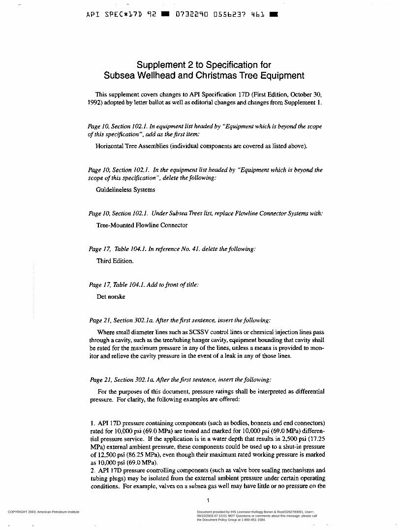
Supplement 2 to Specification for Subsea Wellhead and Christmas Tree Equipment
This supplement covers changes to A P I Specification 17D (First Edition, October 30, 1992) adopted by letter ballot as well as editorial changes and changes from Supplement 1.
Page IO, Section 102. I . In equipment list headed by “Equipment which is beyond the scope of this spec$ication”, add as thePrst item:
Horizontal Tree Assemblies (individual components are covered as listed above).
Page IO, Section 102.1. In the equipment list headed by “Equipment which is beyond the scope of this spec$cation”, delete the following:
Guidelineless Systems
Page IO, Section 102.1. Under Subsea Trees list, replace Flowline Connector Systems with:
Tree-Mounted Flowline Connector
Page 17, Table 104.1. In reference No. 41. delete the following:
Third Edition.
Page 17, Table 104.1. Add to front of title:
Det norske
Page 21, Section 302.la. After thefirst sentence, insert the following:
Where small diameter lines such as SCSSV control lines or chemical injection lines pass through a cavity, such as the weeltubing hanger cavity, equipment bounding that cavity shall be rated for the maximum pressure in any of the lines, unless a means is provided to mon- itor and relieve the cavity pressure in the event of a leak in any of those lines.
Page 21, Section 302.1a. After the$rst sentence, insert the following:
For the purposes of this document, pressure ratings shall be interpreted as differential pressure. For clarity, the following examples are offered:
1. A P I 17D pressure containing components (such as bodies, bonnets and end connectors) rated for 10,OOO psi (69.0 MPa) are tested and marked for 10,OOO psi (69.0 MPa) differen- tial pressure service. If the application is in a water depth that results in 2,500 psi (17.25 MPa) external ambient pressure, these components could be used up to a shut-in pressure of 12,500 psi (86.25 “a), even though their maximum rated working pressure is marked as 10,OOO psi (69.0 MPa). 2. N I 17D pressure controlling components (such as valve bore sealing mechanisms and tubing plugs) may be isolated from the external ambient pressure under certain operating conditions. For example, valves on a subsea gas well may have little or no pressure on the
1
COPYRIGHT 2003; American Petroleum Institute
Document provided by IHS Licensee=Kellogg Borwn & Root/3262700001, User=, 09/10/2003 07:10:01 MDT Questions or comments about this message: please callthe Document Policy Group at 1-800-451-1584.
--`,,,``,```,`,`,``,`,,``,`,,`-`-`,,`,,`,`,,`---
~~
A P I SPECmL7D 92 0732290 0556238 3T8 m
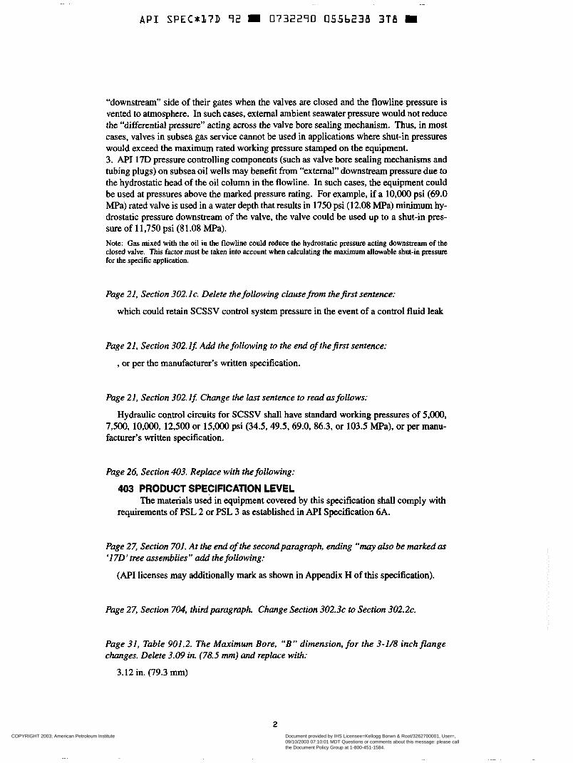
“downstream” side of their gates when the valves are closed and the flowline pressure is vented to atmosphere. In such cases, external ambient seawater pressure would not reduce the “differential pressure” acting across the valve bore sealing mechanism. Thus, in most cases, valves in subsea gas service cannot be used in applications where shut-in pressures would exceed the maximum rated working pressure stamped on the equipment. 3. API 17D pressure controlling components (such as valve bore sealing mechanisms and tubing plugs) on subsea oil wells may benefit from “external” downstream pressure due to the hydrostatic head of the oil column in the flowline. In such cases, the equipment could be used at pressures above the marked pressure rating. For example, if a 10,000 psi (69.0 MPa) rated valve is used in a water depth that results in 1750 psi (12.08 MPa) minimum hy- drostatic pressure downstream of the valve, the valve could be used up to a shut-in pres- sure of 1 1,750 psi (8 1 .O8 MPa). Note: Gas mixed with the oil in the flowline could reduce the hydrostatic pressure acting downstream of the closed valve. This factor must be taken into account when calculating the maximum allowable shut-in pressure for the specific application.
Page 21, Section 302. IC. Delete the following clause fmm thefirst sentence:
which could retain SCSSV control system pressure in the event of a control fluid leak
Page 21, Section 302. If: Add the following to the end of the$rst sentence:
, or per the manufacturer’s written specification.
Page 21, Section 302. If: Change the last sentence to read as follows:
Hydraulic control circuits for SCSSV shall have standard working pressures of 5,000, 7,500, lO,OOO, 12,500 or 15,000 psi (34.5,49.5.69.0, 86.3, or 103.5 MPa), or per manu- facturer’s written specification.
Page 26, Section 403. Replace with the following:
403 PRODUCT SPECIFICATION LEVEL
requirements of PSL 2 or PSL 3 as established in MI Specification 6A. The materials used in equipment covered by this specification shall comply with
Page 27, Section 701. At the end of the second paragraph, ending “may also be marked as ‘1 7 0 ’ tree assemblies” add the following:
(API licenses may additionally mark as shown in Appendix H of this specification).
Page 27, Section 704, third paragraph. Change Section 302.3~ to Section 302.2~.
Page 31, Table 901.2. The Maximum Bore, “B” dimension, for the 3-1/8 inch flange changes. Delete 3.09 in. (78.5 mm) and replace with:
3.12 in. (79.3 mm)
2
COPYRIGHT 2003; American Petroleum Institute
Document provided by IHS Licensee=Kellogg Borwn & Root/3262700001, User=, 09/10/2003 07:10:01 MDT Questions or comments about this message: please callthe Document Policy Group at 1-800-451-1584.
--`,,,``,```,`,`,``,`,,``,`,,`-`-`,,`,,`,`,,`---
A P I SPEC*L?D 92 m 0732290 0.556239 234 m
Pages 33, 34, 35, and 36, Tables 901.3 and 901.4. Replace the two tables with new Tables 901.3 ana‘ 901.4 found in this supplement.
Page 37, Table 901.5. Change Width of Groove, dimension “B,” for Ring Number BX-169 from 0.842 in. (21.39 mm) to:
0.942 in. (23.9 mm)
Pages 38 and 39, Tables 906.1 and 906.2. Lists of tolerances are transposed. Add to Table 906.1 :
Note 3: The list of tolerances in Table 906.1 apply to Table 906.2; and the list in Table 906.2 applies to Table 906. l .
Page 39, Table 906.2. Add:
Note 2: The list of tolerances in Table 906.1 apply to Table 906.2; and the list in Table 906.2 applies to Table 906. l .
Page 40, Section 901.2d. Change the second sentence to read as follows:
If API 6A segmented flanges are used, there shall be at least two pressure controlling valves between the segmented flange and the wellhead.
Page 40, Section 901.2d. Replace the third sentence with the following:
Segmented flanges for use on subsea completion equipment which comply with the requirements of Sections 300 and 904 of this specification do not require the use of two pressure controlling valves between the segmented flange and the wellhead.
Page 40, Paragraph 901.2e(l). To clarify the purpose of the retainer groove on the 17SV flange, after the first sentence add the following:
A retainer groove is provided on the neck of the hub to allow installation of a snap wire of sufficient diameter to hold the ring on the hub during storage, handling and installation.
Page 41, Paragraph 901.3. Replace paragraph with the following:
901.3 MATERIALS. Flange material shall conform to the requirements in Sections 400 and 500 of this specification as applicable, and materials with a minimum yield strength of 75,000 psi (517 MPa) shall be used for Type 17SV Flanges for 10,OOO psi (69.0 MPa) rated working pressure.
Page 43, Section 907.la(2), NOTE TO USER: Delete the word “shouM” ana‘ replace it with shall
3
COPYRIGHT 2003; American Petroleum Institute
Document provided by IHS Licensee=Kellogg Borwn & Root/3262700001, User=, 09/10/2003 07:10:01 MDT Questions or comments about this message: please callthe Document Policy Group at 1-800-451-1584.
--`,,,``,```,`,`,``,`,,``,`,,`-`-`,,`,,`,`,,`---
~ ~~ ~~ ~
A P I S P E C r 1 7 D 92 m 0732290 0556240 T56 m
Page 43, Section 907.la(2), NOTE TO USER: Add the following phrase to the end of the sentence:
..., unless relief is provided as described in Section 302.la of this specification.
Page 43, Section 907.1 b(2). Add to the last sentence:
..., unless relief is provided as described in Section 302.la of this specification.
Page 45, Section 908.2a(I). Add to the end of the third paragraph:
..., unless relief is provided as described in Section 302.la of this specification.
Page 53, Section 912.2b. Add to the end of the second bullet:
..., unless relief is provided as described in Section 302.laof this specification.
Page 53, Section 912.2~(2). Add to the end of the NOTE TO USER:
..., unless relief is provided as described in Section 302. l a of this specification.
Page 53, Section 912.2~(3). Add to thePrst sentence of NOTE TO USER:
..., unless relief is provided as described in Section 302. la of this specification.
Page 56, Section 915.1. Zn thefirst sentence: replace “...flowline connector system” with:
. .. tree-mounted flowline connector systems
Page 56, Section 915. I . Delete the last sentence.
Page 62, Section 919.3b(3)(a). Add the following to the end of the sentence:
, or per the manufacturer’s written specification.
Page 83, Section 1001.5b(4) Change “(see Section 1002.2d)” to:
(see Sections 302.la and 1002.2d of this specification).
Page 86, Section 1002.2d. Add the following to thefirst sentence:
..., unless relief is provided as described in Section 302. l a of this specification.
Page 109, Appendix D. Replace the existing Appendix D with the revised Appendix D found in this supplement.
4
COPYRIGHT 2003; American Petroleum Institute
Document provided by IHS Licensee=Kellogg Borwn & Root/3262700001, User=, 09/10/2003 07:10:01 MDT Questions or comments about this message: please callthe Document Policy Group at 1-800-451-1584.
--`,,,``,```,`,`,``,`,,``,`,,`-`-`,,`,,`,`,,`---
A P I SPEC*17D 92 m 0732290 0556243 972
Page 116, Appendix H. Add the following new paragraph after existing text:
Horizontal tree assemblies are beyond the scope of API Specification 17D and may not be marked with the NI Monogram. However, components of horizontal tree assemblies are covered as listed in Section 102.1 and may be marked with the API Monogram if they comply with all applicable requirements of Specification 17D.
The 17th Edition of AF'I Specification 6A has changed its numbering system considerably, so that all the specific Specification 6A references in API Specification 17D are now in- correct. Following is a list of A P I Specification 17D sections that contain specific Specifi- cation 6A references. All specific Specification 6A section numbers should be deleted in these references.
301.4 302.1 a 302.3a 302.3b (two references) 303.2 303.3 303.4 304.4 304.5 305 40 1 402 501 502 503 60 1
606 901.1 (two references) 901.2b( 1) 901.2b(2)(c) 901.2b(3) 901 .2~ 901.2d 901.2f 901.2h 903 906 .2~ 906.3a 908.1a(2) (two references) 908.2a( 1) 908.2a(2)(b) 908.5b( 1)
908.5b(2) 919.2b 919.3c(2) 919.4c(1) 922.4b lOOlSd(2) 1001.6b(2) 1002.4b( 1) 1101.1 1101.2a Appendix A, Table Al ,
Appendix E, El Appendix G, G2.2 Appendix H, H l
footnote
5
COPYRIGHT 2003; American Petroleum Institute
Document provided by IHS Licensee=Kellogg Borwn & Root/3262700001, User=, 09/10/2003 07:10:01 MDT Questions or comments about this message: please callthe Document Policy Group at 1-800-451-1584.
--`,,,``,```,`,`,``,`,,``,`,,`-`-`,,`,,`,`,,`---
~~
A P I SPECx17D 92 0732290 0556242 8 2 9
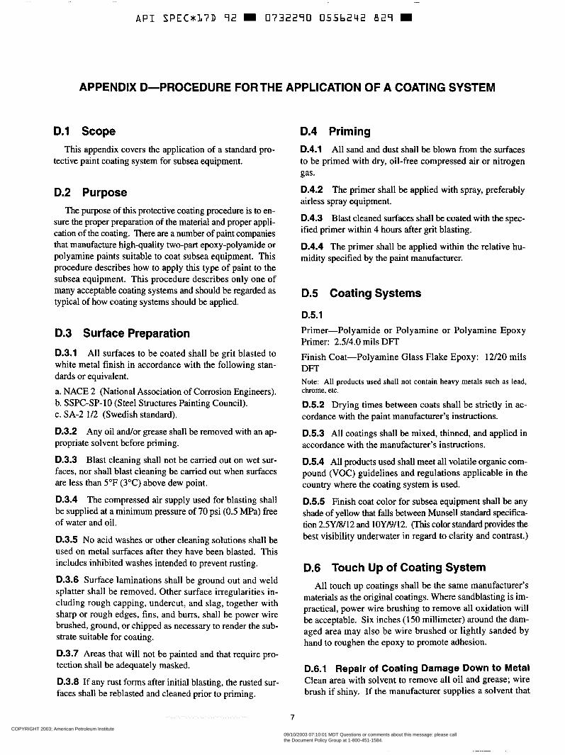
APPENDIX D-PROCEDURE FORTHE APPLICATION OF A COATING SYSTEM
D.1 Scope This appendix covers the application of a standard pro-
tective paint coating system for subsea equipment.
D.2 Purpose The purpose of this protective coating procedure is to en-
sure the proper preparation of the material and proper appli- cation of the coating. There are a number of paint companies that manufacture high-quality two-part epoxy-polyamide or polyamine paints suitable to coat subsea equipment. This procedure describes how to apply this type of paint to the subsea equipment. This procedure describes only one of many acceptable coating systems and should be regarded as typical of how coating systems should be applied.
D.3 Surface Preparation
D.3.1 All surfaces to be coated shall be grit blasted to white metal finish in accordance with the following stan- dards or equivalent.
a. NACE 2 (National Association of Corrosion Engineers). b. SSPC-SP-10 (Steel Structures Painting Council). c. SA-2 1/2 (Swedish standard).
0.3.2 Any oil and/or grease shall be removed with an ap- propriate solvent before priming.
D.3.3 Blast cleaning shall not be carried out on wet sur- faces, nor shall blast cleaning be carried out when surfaces are less than 5°F (3°C) above dew point.
D.3.4 The compressed air supply used for blasting shall be supplied at a minimum pressure of 70 psi (0.5 MPa) free of water and oil.
D.3.5 No acid washes or other cleaning solutions shall be used on metal surfaces after they have been blasted. This includes inhibited washes intended to prevent rusting.
D.3.6 Surface laminations shall be ground out and weld splatter shall be removed. Other surface irregularities in- cluding rough capping, undercut, and slag, together with sharp or rough edges, fins, and burrs, shall be power wire brushed, ground, or chipped as necessary to render the sub- strate suitable for coating.
D.3.7 Areas that will not be painted and that require pro- tection shall be adequately masked.
D.3.8 If any rust forms after initial blasting, the rusted sur- faces shall be reblasted and cleaned prior to priming,
D.4 Priming D.4.1 All sand and dust shall be blown from the surfaces to be primed with dry, oil-free compressed air or nitrogen gas.
D.4.2 The primer shall be applied with spray, preferably airless spray equipment.
0.4.3 Blast cleaned surfaces shall be coated with the spec- ified primer within 4 hours after grit blasting.
D.4.4 The primer shall be applied within the relative hu- midity specified by the paint manufacturer.
D.5 Coating Systems
D.5.1 Primer-Polyamide or Polyamine or Polyamine Epoxy Primer: 2 3 4 . 0 mils DFT Finish Coat-Polyamine Glass Flake Epoxy: 12/20 mils DFT Note: All products used shall not contain heavy metals such as lead, chrome, etc.
D.5.2 Drying times between coats shall be strictly in ac- cordance with the paint manufacturer’s instructions.
D.5.3 All coatings shall be mixed, thinned, and applied in accordance with the manufacturer’s instructions.
D.5.4 All products used shall meet all volatile organic com- pound (VOC) guidelines and regulations applicable in the country where the coating system is used.
0.5.5 Finish coat color for subsea equipment shall be any shade of yellow that falls between Munsell standard specifica- tion 2.5Y/8/12 and 10YB/12. (This color standard provides the best visibility underwater in regard to clarity and contrast.)
D.6 Touch Up of Coating System All touch up coatings shall be the same manufacturer’s
materials as the original coatings. Where sandblasting is im- practical, power wire brushing to remove all oxidation will be acceptable. Six inches (150 millimeter) around the dam- aged area may also be wire brushed or lightly sanded by hand to roughen the epoxy to promote adhesion.
D.6.1 Repair of Coating Damage Down to Metal Clean area with solvent to remove all oil and grease; wire brush if shiny. If the manufacturer supplies a solvent that
7
COPYRIGHT 2003; American Petroleum Institute
Document provided by IHS Licensee=Kellogg Borwn & Root/3262700001, User=, 09/10/2003 07:10:01 MDT Questions or comments about this message: please callthe Document Policy Group at 1-800-451-1584.
--`,,,``,```,`,`,``,`,,``,`,,`-`-`,,`,,`,`,,`---
~ - ~~
A P I SPEC*:L7D 72 W O732270 0556243 765 m
8 API RECOMMENDED PRACTICE 17D
will assist in repair, apply the solvent to the coated areas ad- jacent to the damaged area. When the adjacent coating be- comes tacky, apply the coating system described in Section 5.
D.6.2 Repair of Epoxy Coating Damage Non-
Sandpaper and feather out area to be repaired. Clean off with dry oil-free compressed air or nitrogen gas. Apply to high solid epoxy coatings as necessary to achieve the orig- inal finish.
Extending to Metal
D.7 Inspection D.7.1 A calibrated paint film thickness device shall be used to measure the dry film thickness at each stage of the painting process.
0.7.2 When dry film thicknesses are less than those specified, additional coatings shall be applied as nec- essary to achieve specified thickness.
D.7.3 A11 coatings shall be free of pin holes, voids, bubbles and other holidays.
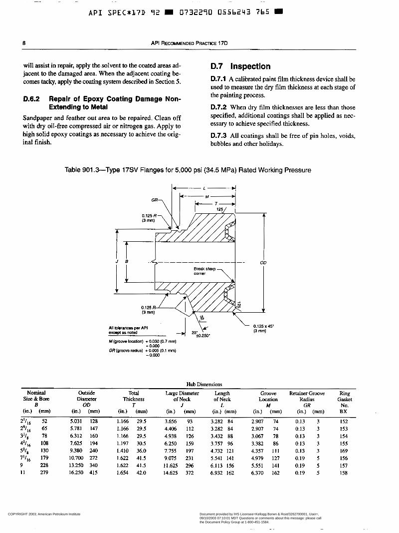
Table 901 .%Type 17SV Flanges for 5,000 psi (34.5 MPa) Rated Working Pressure
All tolerams per API except as noted
M(groove location) + 0.030 (0.7 mm)
GR (groove radius) + 0.005 (0.1 mm) - 0 . m
- 0.m
Hub Dimensions Nominal Outside Total
Size & Bore large Diameter Length
Diameter Thickness of Neck of Neck Groove Retainer Groove Ring
Location Radius Gasket
(in.) (m) (in.) (m) (in.) (mm) (in.) (mm) (in.) (mm) (in.) (mm) (in.) (mm) BX No.
2'I,, 52 5.031 128 1.166 29.5 3.656 93 3.282 84 2.907 74 0.13 3 152
3'18 78 6.312 160 1.166 29.5 4.938 126 3.432 88 3.067 78 0.13 3 154
41/,6 108 7.625 194 1.197 30.5 6.250 159 3.757 96 3.382 86 0.13 3 155
5'18 130 9.380 240 1.410 36.0 7.755 197 4.732 121 4.357 111 0.13 3 169 7'/,, 179 10.700 272 1.622 41.5 9.075 231 5.541 141 4.979 127 0.19 5 156
11 279 16.250 415 1.654 42.0 14.625 372 6.932 162 6.370 162 0.19 5 I58
B OD T M GR J L
294, 65 5.781 147 1.166 29.5 4.406 112 3.282 84 2.907 74 0.13 3 153
9 228 13.250 340 1.622 41.5 11.625 296 6.113 156 5.551 141 0.19 5 157
COPYRIGHT 2003; American Petroleum Institute
Document provided by IHS Licensee=Kellogg Borwn & Root/3262700001, User=, 09/10/2003 07:10:01 MDT Questions or comments about this message: please callthe Document Policy Group at 1-800-451-1584.
--`,,,``,```,`,`,``,`,,``,`,,`-`-`,,`,,`,`,,`---
SUPPLEMENT 2 TO SPECIFICATION FOR SUBSEA WELLHEAD AND CHRISTMAS TREE EQUIPMENT 9
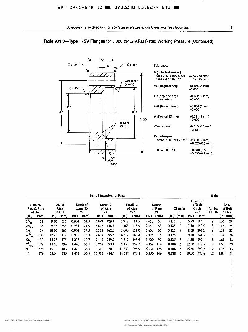
Table 901 .&Type 17SV Flanges for 5,000 (34.5 MPa) Rated Working Pressure (Continued)
cx450 7
t c x 45"
L 3 c x 45" Tolerance:
R (outside diameter) Size 2-1/16 thru 5-1/8 33.062 (2 mm) Size 7-1/16 thru 11 39.125 (3 mm)
RL (length of ring) +0.125 (3 mm) -0.000
RT(depth of large +0.062 (2 mm) diameter) -0.ooo
W1 (large ID ring) -0.ooo +0.031 (1 mm)
W 2 (small ID ring) +0.031 (1 mm) -0.Ooo
C (chamfer) +0.010 (0.3 mm) -0.OOo
Bolt diameter Size 2-1/16 thru 7-1/16 +0.060 (2 mm)
-0.020 (0.5 mm)
Size 9 thru 11 + 0.090 (2.5 mm) -0.020 (0.5 mm)
YI 2> f.250"
Basic Dimensions of Ring Bolts
Nominal OD of Depth of Large ID Small ID Length of Bolt Size & Bore Ring Large ID of Ring of Ring of Ring
of Hub R OD RT RJ1 RJ2 RL C BC of Bolts Holes Chamfer Circle Number of Bolt
(in.) (mm) (in.) (mm) (in.) (mm) (in.) (mm) (in.) (mm) (in.) (mm) (in.) (mm) (in.) (nun) (in.) (nun)
21/,6 52 8.50 216 0.964 24.5 5.093 129.4 3.718 94.5 2.450 63 0.125 3 6.50 165.1 8 1.00 26 29/1 65 9.62 246 0.964 24.5 5.843 148.5 4.468 113.5 2.450 63 0.125 3 7.50 190.5 8 1.12 29 311, 78 10.50 267 0.964 24.5 6.375 162.0 5.000 127.0 2.600 66 0.125 3 8.00 203.2 8 1.25 32 4 'I,, 103 12.25 312 0.965 25.3 7.687 195.3 6.312 160.4 2.925 75 0.125 3 9.50 241.3 8 1.38 36
130 14.75 375 1.208 30.7 9.442 239.9 7.817 198.6 3.900 99 0.125 3 11.50 292.1 8 1.62 42 71/,6 179 15.50 394 1.420 36.1 10.762 273.4 9.157 232.1 4.459 114 0.188 5 12.50 317.5 12 1.50 39 9 228 19.00 483 1.420 36.1 13.312 338.2 11.687 296.9 5.031 128 0.188 5 15.50 393.7 12 1.75 45 11 279 23.00 585 1.452 36.9 16.312 414.4 14.687 373.1 5.850 149 0.188 5 19.00 482.6 12 2.00 51
Diameter Dia.
COPYRIGHT 2003; American Petroleum Institute
Document provided by IHS Licensee=Kellogg Borwn & Root/3262700001, User=, 09/10/2003 07:10:01 MDT Questions or comments about this message: please callthe Document Policy Group at 1-800-451-1584.
--`,,,``,```,`,`,``,`,,``,`,,`-`-`,,`,,`,`,,`---
~~~
A P I SPEC*17D 92 m 0732290 0556245 538 m
10 API RECOMMENDED PRACTICE 17D
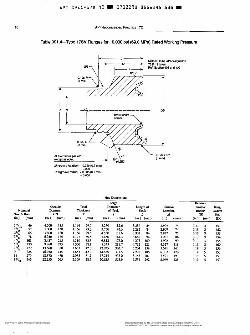
Table 901 .&Type 17SV Flanges for 10,000 psi (69.0 MPa) Rated Working Pressure
Material to be API designation 75 K minimum Ref Section 401 and 402
All tolerances per API except as noted
M (groove location) + 0.030 (0.7 mm)
GR (groove radius) + 0.005 (0.1 mm) - 0 . m
-0.000
Hub Dimensions
Large Outside Total Diameter Length of Groove
Diameter Thickness of Neck OD T J
Neck L
Location M
Retainer Groove Ring Radius Gasket
(in.) (mm) (in.) (mm) (in.) (mm) (in.) (mm) (in.) (mm) (in.) (mm) GR No.
(in.) (mm) BX
1 1 3 1 , ~ 46 4.500 115 1.166 29.5 3.250 82.6 2'Il6 52 5.000 130
3.282 84 2.907 74 1.166 29.5
0.13 3 3.750 95.3
151
291,~ 65 5.800 150 1.166 29.5 4.550 115.6 3.282 84 2.907 74 0.13 3 152 3.302 84
31/,6 78 6.930 175 1.197 30.5 2.927 75
5.680 144.3 0.13 3
3.666 94 153
4'/,6 103 8.437 215 3.291 84 0.13 3 154
1.310 33.3 6.812 178.0 4.277 109 5'1, 130 9.960 225 1.500 38.1
3.902 99 8.335 21 1.7 4.732 121
0.13 3 155
7'/,6 179 4.357 111
6.204 158 0.13 3 1 69
13.660 350 1.653 42.0 12.035 305.7 9 228 16.250 415
5.641 143 0.19 5 156 1.653 42.0 14.625 371.5 7.270 185
11 279 6.707 170
18.870 480 2.035 51.7 17.245 438.0 8.153 207 0.19 5 157
135/, 346 7.591 193 0.19 5 158
22.250 565 2.309 58.7 20.625 523.9 9.531 242 8.969 228 0.19 5 159
Nominal Size & Bore
COPYRIGHT 2003; American Petroleum Institute
Document provided by IHS Licensee=Kellogg Borwn & Root/3262700001, User=, 09/10/2003 07:10:01 MDT Questions or comments about this message: please callthe Document Policy Group at 1-800-451-1584.
--`,,,``,```,`,`,``,`,,``,`,,`-`-`,,`,,`,`,,`---
~~ ~~ ~ ~~
A P I SPECNKL7D 92 0732290 0556246 474
SUPPLEMENT 2 TO SPECIFICATION FOR SUBSEA WELLHEAD AND CHRISTMAS TREE EQUIPMENT 11
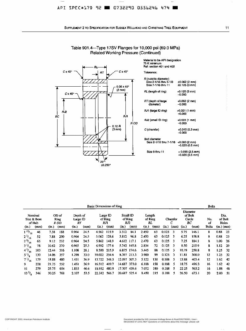
Table 901 .&Type 17SV Flanges for Related Working Pressure
' 10,000 psi (69.0 MPa) (Continued)
Material to be API designation 75 K minimum Ref: section 4 0 1 and 402
Tolerance:
R (outside diameter) Size 2-1/16 thru 5-1/8 33.062 (2 mm) Size 7-1/16 thru 11 M.125 (3 mm)
RL (length of ring) 4.125 (3 mm) -0.Ooo
RT(depth of large 4.062 (2 mm) diameter) 4 O o o
RJI (large ID ring) 4.031 (1 mm) -0.Ooo
R&? (small ID ring) tO.031 (1 mm) -0.000
-0.Ooo tO.010 (0.3 mm) C(chamfer)
Bolt diameter Size 2-1/16 thru 7-1/16 4.060 (2 mm)
-0.020 (0.5 mm)
Size 9 thru 1 1 -0.020 (0.5 mm) + 0.090 (2.5 mm)
Basic Dimensions of Ring Bolts
Diameter Nominal OD of Depth of Large ID Small ID Length of Bolt Dia.
Size Br Bore Ring Large ID of Ring of Ring of Ring Chamfer Circle No. of Bolt of Hub R OD RT R I 1 RJ2 RL C EC of Holes
(in.) (mm) (in.) (mm) (in.) (mm) (in.) (mm) (in.) (mm) (in.) (mm) (in.) (mm) (in.) (mm) Bolts (in.) (mm) 1 13/16 46 7.38 188 0.964 24.5 4.562 115.9 3.312 84.1 2.450 63 0.125 3 5.75 146.1 8 0.88 23 2 I/,, 52 7.88 200 0.964 24.5 5.062 128.6 3.812 96.8 2.450 63 0.125 3 6.25 158.8 8 0.88 23 '19/,, 65 9.12 232 0.964 24.5 5.862 148.9 4.612 117.1 2.470 63 0.125 3 7.25 184.1 8 1.00 26 3 I/ , , 78 10.62 270 0.965 25.3 6.992 177.6 5.742 145.8 2.834 72 0.125 3 8.50 215.9 8 1.12 29 41/16 103 12.44 316 1.108 28.1 8.500 215.9 6.875 174.6 3.445 88 0.125 3 10.19 258.8 8 1.25 32 5 I/, 130 14.06 357 1.298 33.0 10.022 254.6 8.397 213.3 3.900 99 0.125 3 11.81 300.0 12 1.25 32 7 I/,, 179 18.88 480 1.451 36.9 13.722 348.5 12.097 307.3 5.122 130 0.188 5 15.88 403.4 12 1.62 42 9 228 21.75 552 1.451 36.9 16.312 409.7 14.687 373.0 6.188 158 0.188 5 18.75 496.3 16 1.62 42 11 279 25.75 654 1.833 46.6 18.932 480.9 17.307 439.6 7.072 180 0.188 5 22.25 565.2 16 1.88 48 13s/8 346 30.25 768 2.107 53.5 22.312 566.7 20.687 525.4 8.450 215 0.188 5 26.50 673.1 20 2.00 51
COPYRIGHT 2003; American Petroleum Institute
Document provided by IHS Licensee=Kellogg Borwn & Root/3262700001, User=, 09/10/2003 07:10:01 MDT Questions or comments about this message: please callthe Document Policy Group at 1-800-451-1584.
--`,,,``,```,`,`,``,`,,``,`,,`-`-`,,`,,`,`,,`---

Additional copies available from API Publications and Distribution: (202) 682-8375
Information M A P I Publications, Programs and Services is available on the World Wide Web at http:/A.ww.api.org
P American 1220 L Street, Northwest Petroleum Washington, D.C. 20005-4070 Institute 202-682-8000 Order No. G07266
COPYRIGHT 2003; American Petroleum Institute
Document provided by IHS Licensee=Kellogg Borwn & Root/3262700001, User=, 09/10/2003 07:10:01 MDT Questions or comments about this message: please callthe Document Policy Group at 1-800-451-1584.
--`,,,``,```,`,`,``,`,,``,`,,`-`-`,,`,,`,`,,`---
A P I SPECbL7D 92 m 0732290 0508879 b 9 T m
Supplement 1 (March 1, 1993)
Specification for Subsea Wellhead and Christmas Tree Equipment
API SPECIFICATION 17D (SPEC 17D) FIRST EDITION, OCTOBER 30, 1992
American Petroleum Institute 1220 L Street, Northwest Washington, DC 20005 11’
COPYRIGHT 2003; American Petroleum Institute
Document provided by IHS Licensee=Kellogg Borwn & Root/3262700001, User=, 09/10/2003 07:10:01 MDT Questions or comments about this message: please callthe Document Policy Group at 1-800-451-1584.
--`,,,``,```,`,`,``,`,,``,`,,`-`-`,,`,,`,`,,`---
~
A P I S P E C * l 7 D 72 0732290 0508880 301
Issued by AMERICAN PETROLEUM INSTITUTE
Production Department
FOR INFORMATION CONCERNING TECHNICAL CONTENTS OF THIS PUBLICATION CONTACT THE API PRODUCTION DEPARTMENT,
SEE BACK COVER FOR INFORMATION CONCERNING HOW TO OBTAIN ADDITIONAL COPIES OF THIS PUBLICATION.
1201 MAIN STREET, SUITE 2535, DALLAS, TX 75202-3994 - (214) 748-3841.
Users of this publication should become familiar with its scope and content. This publication is intended to supplement rather
than replace individual engineering judgment.
OFFICIAL PUBLICATION
REG. U.S. PATENT OFFICE
Copyright Q 1993 American Petroleum Institute
COPYRIGHT 2003; American Petroleum Institute
Document provided by IHS Licensee=Kellogg Borwn & Root/3262700001, User=, 09/10/2003 07:10:01 MDT Questions or comments about this message: please callthe Document Policy Group at 1-800-451-1584.
--`,,,``,```,`,`,``,`,,``,`,,`-`-`,,`,,`,`,,`---
Sup 1, Spec 17D: Subsea Wellhead and Christmas Tree Equipment 1
Foreword This supplement covers changes in API Spec 17D, First Edition, October 30, 1992, adopted by letter ballot as well as editorial changes.
Page 17, Table 104.1. Delete edition number in refer- ence No. 41.
Page 17, Table 104.1. Add “Det norske” to front of title.
Page 26. Section 403. Replace with the following:
“403 PRODUCT SPECIFICATION LEVEL. The materials used in equipment covered by this specifi- cation shall comply with requirements of PSL 2 or PSL 3 as established in API Specification 6A.”
Page 27, Section 704, third paragraph. Change “302.3~” to “302.2~”.
Pages 33, 34, 35 and 36, Tables 901.3 and 901.4. Replace the two tables with those on ¿he following four pages.
Attention Users of this Publication: Portions of this publication have been changed &om the previous edition. The location of changes has been marked with a bar in the margin. In some cases the changes are significant, while in other cases the changes reflect minor editorial adjust- ments. The bar notations in the margins are provided as an aid to users to identify those parts of this publication that have been changed from the previous edition, but A P I makes no warranty as to the accuracy of such bar notations.
COPYRIGHT 2003; American Petroleum Institute
Document provided by IHS Licensee=Kellogg Borwn & Root/3262700001, User=, 09/10/2003 07:10:01 MDT Questions or comments about this message: please callthe Document Policy Group at 1-800-451-1584.
--`,,,``,```,`,`,``,`,,``,`,,`-`-`,,`,,`,`,,`---
A P I SPEC*:LIID 92 0732290 0508882 LBLt D
2 American Petroleum Institute
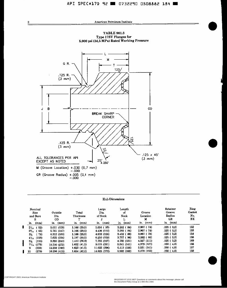
TABLE 901.3 Type 17SV Flanges for
5,000 psi (34,5 MPa) Rated Working Pressure
J B OD
ALL TOLERANCES PER API EXCEPT AS NOTED
M (Groove Location) +.O30 (0,7 mm)
GR (Groove Radius) +.O05 (0,l mm) - .o00
-.o00
Hub Dimensions
Outside Dia. OD
in. (mm) 5.031 (128) 5.781 (147) 6.312 (160) 7.625 (194) 9.380 (240) 10.700 (272) 13.250 (340) 16.250 (415)
Total Thickness
T in. (mm)
1.166 (29.5) 1.166 (29.5) 1.166 (29,5) 1.197 (30.6) 1.410 (36,O) 1.622 (41,5) 1.622 (41,5) 1.654 (42,O)
Large Dia.
of Neck J
in. (mm) 3.656 ( 93)
4.938 (126) 6.250 (159) 7.755 (197) 9.075 (281) 11.625 (296) 14.625 (372)
4.406 (112)
Length of
Neck L
in. (mm) 3.282 ( 84) 3.282 ( 84) 3.432 ( 88) 3.767 ( 96) 4.732 (121) 6.541 (141) 6.113 (156) 6.932 (162)
Retainer Groove Groove
Location Radius M GR
in. (mm) in. (mm) 2.907 ( 74) .126 ( 3,2) 2.907 ( 74) .125 ( 3.2) 3.067 ( 78) .125 ( 3,2) 3.382 ( 86) .125 ( 3,2) 4.357 (111) .125 ( 3,2) 4.979 (127) J88 ( 4,8) 5.551 (141) .188 ( 4.8) 6.370 (162) .188 ( 4.8)
Ring Gasket
No. BX
152 153 154 155 169 156 157 158
COPYRIGHT 2003; American Petroleum Institute
Document provided by IHS Licensee=Kellogg Borwn & Root/3262700001, User=, 09/10/2003 07:10:01 MDT Questions or comments about this message: please callthe Document Policy Group at 1-800-451-1584.
--`,,,``,```,`,`,``,`,,``,`,,`-`-`,,`,,`,`,,`---
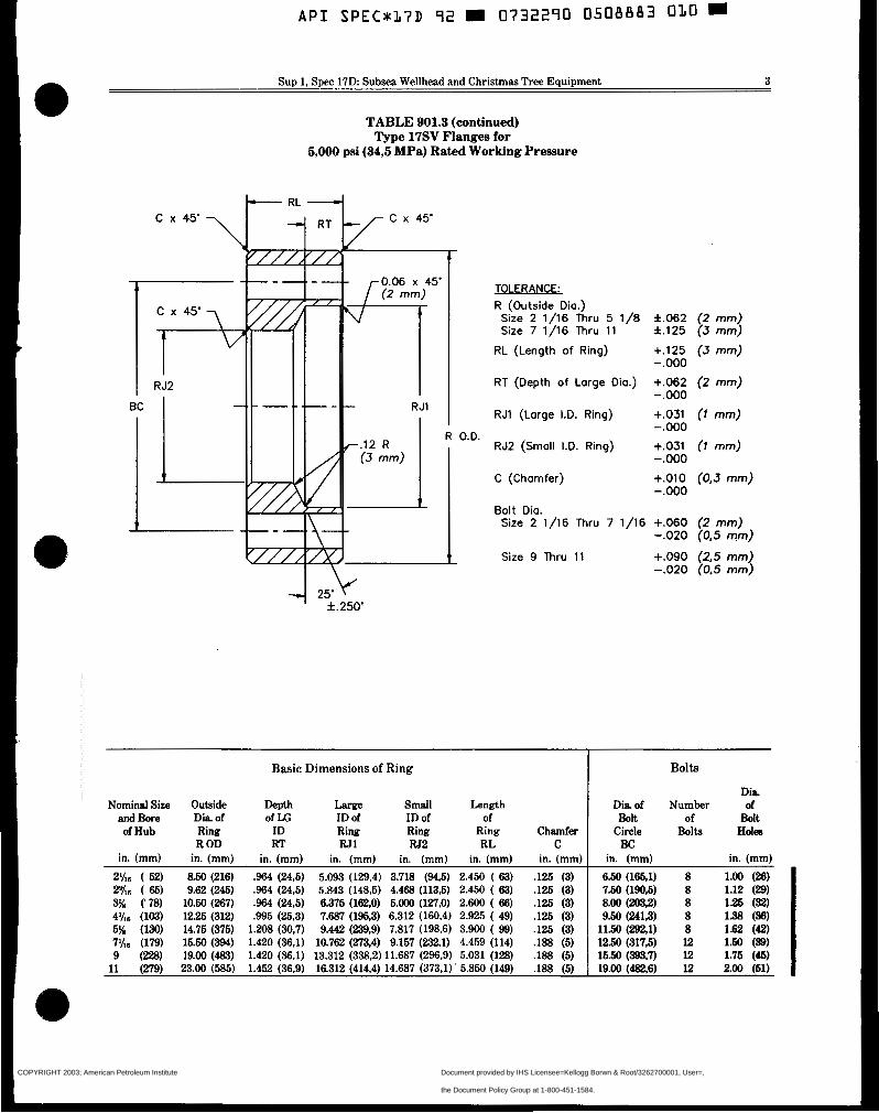
Sup 1, Spec 17D Subsea Wellhead and Christmas Tree Equipment 3
TABLE 901.3 (continued) Type 17SV Flanges for
5,000 psi (34,5 MPa) Rated Working Pressure
TOLFRANCF. R (Outside Dia.)
Size 2 1/16 Thru 5 1/8 Size 7 1 /16 Thru 11
RL (Length of Ring)
RT (Depth of Large Dia.)
RJl (Large I.D. Ring)
RJ2 (Small I.D. Ring)
C (Chamfer)
Bolt Dia. Size 2 1/16 Thru 7 1/16
Size 9 Thru 11
4 2,.\c' f . 2 5 0 '
Nominal Size and Bore of Hub
Outside Dia of Ring R OD
in. (mm) 8.50 (216) 9.62 (245) 10.50 (267) 12.26 (312) 14.75 (375) 15.50 (394) 19.00 (483) 23.00 ( 5 8 5 )
Basic Dimensions of Ring
Depth Large Small of IÆ
Length ID of ID of of
ID RT
Ring RJ1
Ring RJ2
Ring RL
in. (mm) in. (mm) in. (mm) in. (mm)
Chamfer C
in. (mm) .964 (24.5) 5.093 (129,4) 3.718 (94.5) 2.450 ( 63) .964 (24,5) 5.843 (148,5) 4.468 (113,5) 2.450 ( 63) .W (24,5) 6.376 (162,O) 5.000 (127.0) 2.600 ( 66) .!W5 (25.3) 7.687 (195.3) 6.312 (160.4) 2.925 ( 49) 1.208 (30,7) 9.442 (239,9) 7.817 (198,6) 3.900 ( 99) 1.420 (36.1) 10.762 (273,4) 9.157 (232.1) 4.459 (114) 1.420 (36.1) 13.312 (338,2) 11.687 (296.9) 5.031 (128) 1.452 (36.9) 16.312 (414.4) 14.687 (373.1) 5.850 (149)
.125 (3)
.125 (3)
.125 (3)
.125 (3)
.125 (3)
.188 (5)
.188 (5)
.188 (5)
f .062 f . 1 2 5
+.125 -.o00 +.O62 -.o00 + ,031 - * O00 +.O31 -.OD0
+.o10 -.o00
+.O60 -.o20
+.o90
Bolts
Dia Diaof Number of Bolt of Bolt
Circle Bolts BC
Holes
in. (mm) in. (mm)
6.50 (166,l) 8 1.00 (B) 7.50 (lW.6) 8 1.12 (29) 8.00 (W) 8 12 5 (SZ) 9.50 (2413) 8 1.38 (36) 11.50 (292.1) 8 1.62 (42) 12.50 (3175) 12 1.60 (SS) 16.50 (393.7) 12 1.75 (46) 19.00 ( a 6 ) 12 200 (SI)
COPYRIGHT 2003; American Petroleum Institute
Document provided by IHS Licensee=Kellogg Borwn & Root/3262700001, User=, 09/10/2003 07:10:01 MDT Questions or comments about this message: please callthe Document Policy Group at 1-800-451-1584.
--`,,,``,```,`,`,``,`,,``,`,,`-`-`,,`,,`,`,,`---
API SPEC*L7D 92 m 0732290 0508884 T57 m
4 American Petroleum Institute
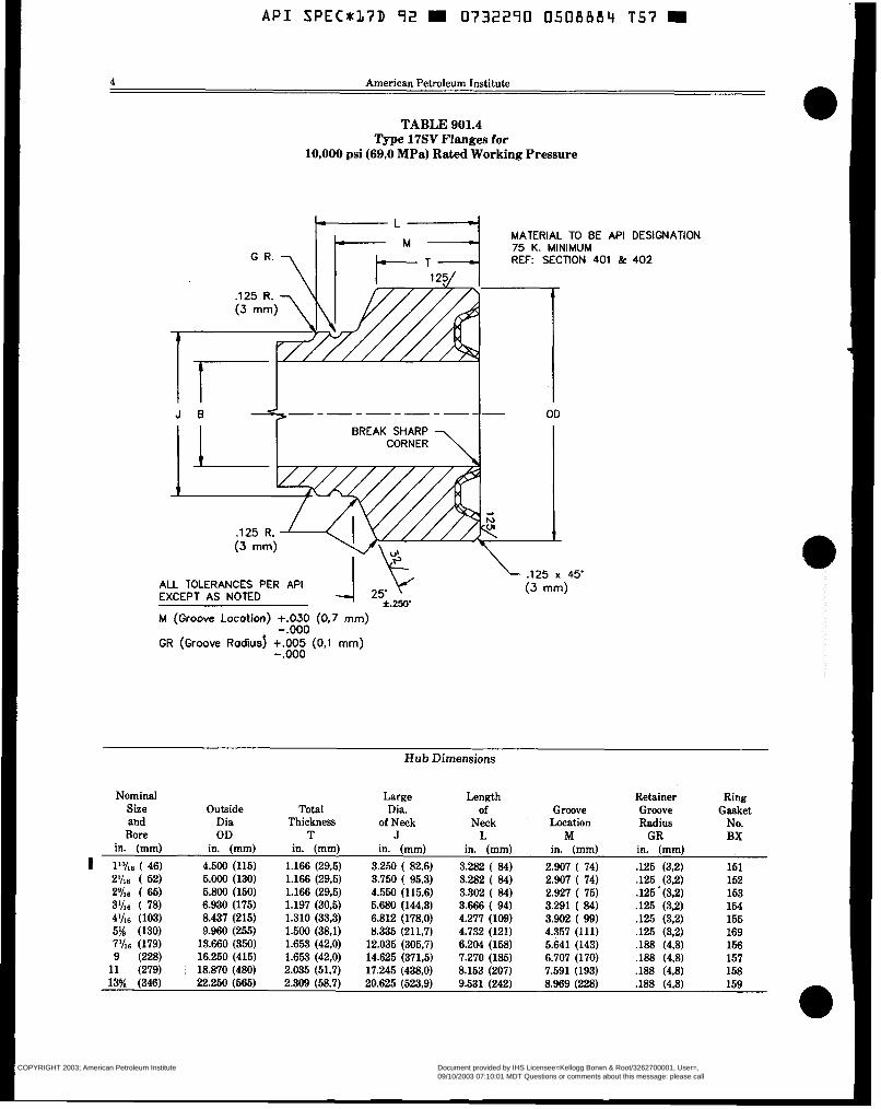
TABLE 901.4 Type 17SV Flanges for
10,000 psi (69,O MPa) Rated Working Pressure
MATERIAL TO BE API DESIGNATION 75 K. MINIMUM REF SECTION 401 k 402
BREAK SHARP
ALL TOLERANCES PER API EXCEPT AS NOTED
M (Groove Locotion) +.O30 (0,7 mm)
GR (Groove Radius) +.O05 (0,l mm) -.o00
-.o00
Hub Dimensions
Nominal Large Length Size Outside Total
Retainer Ring Dia.
and Dia Groove
Thickness of Neck Neck Location Groove Radius
Gasket
Bore OD T J L M GR BX No.
of
in. (mm) in. (mm) in. (mm) in. (mm) in. (mm) in. (mm) in. (mm)
1 1%6 ( 46) 4.500 (115) 1.166 (29,5) 3.250 ( 82.6) 3.282 ( 8 4 ) 2.907 ( 74) J25 (3,2) 151 2%6 ( 52) 5.000 (130) 1.166 (29,5) 3.750 ( 95.3) 3.282 ( 8 4 ) 2.907 ( 74) .125 (3,2) 152 2% ( 65) 5.800 (150) 1.166 (29,5) 4.550 (115,6) 3.302 ( 8 4 ) 2.927 ( 75) .125 ' (3,2) 153 3%6 ( 78) 6.930 (175) 1.197 (30,5) 5.680 (144,3) 3.666 ( 94) 3.291 ( 8 4 ) .125 (3.2) 164 4 % ~ (103) 8.437 (215) 1.310 (33,3) 6.812 (178,O) 4.277 (109) 3.902 ( 99) .125 (3,2) 155 5% (130) 9.960 (255) 1.500 (38.1) 8.335 (211,7) 4.732 (121) 4.357 (111) .125 (3,2) 169
9 (228) 16.250 (415) 1.653 (42,O) 14.625 (371.5) 7.270 (185) 6.707 (170) .188 (4,8) 157 11 (279) 1 18.870 (480) 2.035 (51.7) 17.245 (438.0) 8.153 (207) 7.591 (193) ,188 (4.8) 158 13% (346) 22.250 (665) 2.309 (58,í') 20.625 (523,9) 9.531 (242) 8.969 (228) .188 (4,8) 159
7%6 (179) 13.660 (350) 1.653 (42,O) 12.035 (305,7) 6.204 (158) 5.641 (143) ,188 (4,8) 156
COPYRIGHT 2003; American Petroleum Institute
Document provided by IHS Licensee=Kellogg Borwn & Root/3262700001, User=, 09/10/2003 07:10:01 MDT Questions or comments about this message: please callthe Document Policy Group at 1-800-451-1584.
--`,,,``,```,`,`,``,`,,``,`,,`-`-`,,`,,`,`,,`---
API SPEC*:L7D 72 0732270 0508885 993
Sup 1, Spec 17D: Subsea Wellhead and Christmas Tree Equipment 5
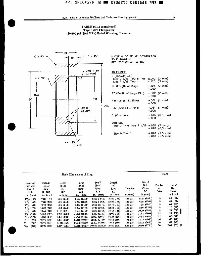
TABLE 901.4 (continued) Type 17SV Flanges for
10,000 psi (69,O MPa) Rated Working Pressure
MATERIAL TO BE API DESIGNATION 75 K. MINIMUM REF. SECTION 401 & 402
TOI FRANCF. R (Outside Dia.)
Size 2 1/16 Thru 5 1/8 f.062 (2 mm) Size 7 1/16 Thru 11 f.125 (3 mm)
4 25.v f.250‘
O.D.
RL (Length of Ring) +.125 (3 mm)
RT (Depth of Large Dia.) +.O62 (2 mm)
RJl (Large I.D. Ring) +.O31 ( 1 mm)
-.o00
-.o00
- . O00 RJ2 (Small I.D. Ring) +.O31 ( 1 mm)
C (Chamfer) +.O10 (0,3 mm)
Bolt Dia.
- . O00
- . O00
Size 2 1/16 Thru 7 1/16 +.O60 (2 mm) -.O20 (0.5 mm)
Size 9 .Thru 11 +.O90 (2.5 mm) -.O20 (0.5 mm)
Basic Dimensions of Ring Bolts
Nominal Outside Depth kse Small Length Dia of Size and Dia. of of u: LD. of ID of of Bolt Number Dia of Bore of Ring ID Ring Ring Ring Chamfer Circle of Bolt
Hub R OD RT N1 W 2 RL C BC Bolts Holes in. (mm) in. (mm) in. (mm) in. (mm) in. (mm) in. (mm) in. (mm) in.(mm) in. (mm)
l l K s ( 46) 7.38 (188) .964 (24,5) 4.562 (115,9) 3.312 ( 84.1) 2.450 ( 63) .125 (,3) 5.75 (146,l) 8 .88 (23) 2Yl6 ( 52) 7.88 (200) .964 (24,5) 5.062 (128,6) 3.812 ( 963) 2.450 ( 63) .125 (,3) 6.25 (158,8) 8 .88 (23) 29/,6 ( 65) 9.12 (232) .964 (24,5) 5.862 (148.9) 4.612 (117,l) 2.470 ( 63) .125 (,3) 7.25 (184.1) 8 1.00 (26) 3Ih6 ( 78) 10.62 (270) .995 (25,3) 6.992 (177,6) 5.742 (145.8) 2.834 ( 72) .125 (,3) 8.50 (215.9) 8 1.12 (B)
5% (130) 14.06 (357) 1.298 (33,O) 10.022 (254,6) 8.397 (213,3) 3.900 ( 99) .125 (,3) 11.81 (300,O) 12 1.25 (32)
9 (228) 21.75 (552) 1.451 (36.9) 16.312 (409.7) 14.687 (373,O) 6.188 (158) .188 (,5) 18.75 (496.3) 16 1.62 (42) 11 (279) 25.75 (654) 1.833 (46,6) 18.932 (480,9) 17307 (439.6) 7.072 (180) .188 (,5) 22.25 (566,2) 16 1.88 (48) 13% (346) 30.25 (768) 2.107 (533) 22.312 (566,7) 20.687 (525,4) 8.4w (215) 1.88 (.5) 26.50 (673.1) 20 2.00 (51) I
4’/16 (103) 12.44 (316) 1.108 (28,i) 8.500 (215,9) 6.875 (174,6) 3-46 ( 88) .I25 (,3) 10.19 (2588 8 126 (32) I 711,~ (179) 18.88 (480) 1.451 ( 3 ~ ) 13.722 (3465) 12.097 (307,3) 5.122 (130) .W (,5) 15.88 (403.4) 12 1.62 (42)
COPYRIGHT 2003; American Petroleum Institute
Document provided by IHS Licensee=Kellogg Borwn & Root/3262700001, User=, 09/10/2003 07:10:01 MDT Questions or comments about this message: please callthe Document Policy Group at 1-800-451-1584.
--`,,,``,```,`,`,``,`,,``,`,,`-`-`,,`,,`,`,,`---
A P I SPEC*L7D 92 W 0732290 0.508886 82T W
Order No. 811-07266
Additional copies available from AMERICAN PETROLEUM INSTITUTE Publications and Distribution Section 1220 L Street, NW Washington, DC 20005 (202) 682-8375
COPYRIGHT 2003; American Petroleum Institute
Document provided by IHS Licensee=Kellogg Borwn & Root/3262700001, User=, 09/10/2003 07:10:01 MDT Questions or comments about this message: please callthe Document Policy Group at 1-800-451-1584.
--`,,,``,```,`,`,``,`,,``,`,,`-`-`,,`,,`,`,,`---
Specification for Subsea Wellhead and Christmas Tree Equipment
API SPECIFICATION 17D (SPEC 17D) FIRST EDITION, OCTOBER 30, 1992
American Petroleum Institut 1220 L Street, Northwest
e
Washington, DC 20ö05
rT,
COPYRIGHT 2003; American Petroleum Institute
Document provided by IHS Licensee=Kellogg Borwn & Root/3262700001, User=, 09/10/2003 07:10:01 MDT Questions or comments about this message: please callthe Document Policy Group at 1-800-451-1584.
--`,,,``,```,`,`,``,`,,``,`,,`-`-`,,`,,`,`,,`---
Issued by AMEMCANPETROLEXJMINSTITUTE
Production Department
FOR INFORMATION CONCERNING TECHNICAL CONTENT OF THIS PUBLICATION CONTACT THE API PRODUCTION DEPARTMENT,
1201 MAIN STREET, SUITE 2535, DALIAS, TX 75202-3904 - (214) 748-3841. SEE BACK COVER FOR INFORMATION CONCERNING HOW TO OBTAIN
ADDITIONAL COPIES OF THIS PUBLICATION.
. .
Users of this publication should become familiar with its scope and content, including any provisions it may have regarding marking of manufactured
products. This putilication is intended to supplement rafher than replace Individual engineering judgment.
Copyright O 1992 American Petroleum Institute
OFFICIAL PUBLICATION
REQ. U.S. PATENT OFFICE
COPYRIGHT 2003; American Petroleum Institute
Document provided by IHS Licensee=Kellogg Borwn & Root/3262700001, User=, 09/10/2003 07:10:01 MDT Questions or comments about this message: please callthe Document Policy Group at 1-800-451-1584.
--`,,,``,```,`,`,``,`,,``,`,,`-`-`,,`,,`,`,,`---
. API SPECn17D 92 0732290 0501594 L m !?!B
.,
2 American Petroleum Institute
TAJ3LX OF CONTENTS Page POLICY ....................................................................................................................................... 8 FOREWORD ............................................................................................................................... 9 100 SCOPE
101 Purpose ......................................................................................................................... 10 102 Applications .................................................................................................................. 10
102.1 Equipment .......................................................................................................... 10 102.2 Service Conditions .............................................................................................. 10
104 Referenced Standards ................................................................................................... 16 104.1 General ............................................................................................................... 16 104.2 Requirements ..................................................................................................... 16 104.3 Equivalent Standards ......................................................................................... 16
105 Units ............................................................................................................................. 16 106 Appendixes .................................................................................................................... 16
201 Abbreviations ................................................................................................................ 18 202 Definitions .................................................................................................................... 18
301 Performance Requirements ........................................................................................... 21 301.1 General ............................................................................................................... 21
301.3 Thermal Integrity ............................................................................................... 21 301.4 Materials ............................................................................................................ 21 301.5 Leakage .............................................................................................................. 21 301.6 Load Capability ........................................ i .......................................................... 21 301.7 Cycles ................................................................................................................. 21
302 Service Conditions ......................................................................................................... 21
302.2 Temperature Ratings .......................................................................................... 21 302.3 Materials Class Ratings ....................................................................................... 21 302.4 External Hydrostatic Pressure ............................................................................ 22
303 Design Methods ............................................................................................................ 22 303.1 Standard API Flanges and Hubs ........................................................................ 22 303.2 Pressure Controlling Components ...................................................................... 22
303.4 Closure Bolting ................................................................................................... 22
303.6 Specific Equipment ............................................................................................. 22 303.7 Design ofLaing Devices .................................................................................... 22
304 Miscellaneous Design Information ................................................................................ 22 304.1 General ............................................................................................................... 22 304.2 Fraction to Decimal Equivalence ........................................................................ 22 304.3 Tolerances ........................................................................................................... 22
304.5 Test. Vent. Injection. and Gage Connections ....................................................... 23 304.6 External Corrosion Control Program .................................................................. 23
103 Product Specification Levels (PSL) ................................................................................ 10
200 ABBREVIATIONS/DEFINITIONS
300 DESIGN AND PERFORMANCE - GENERAL REQUIREMENTS
301.2 Pressure Integrity ............................................................................................... 21
301.8 Operating Force or Torque .................................................................................. 21
302.1 Pressure Ratings ................................................................................................. 21
303.3 Pressure Containing Components ....................................................................... 22
303.5 Unpressurized Primary Structural Components ................................................. 22
304.4 Bolting ................................................................................................................ 23
COPYRIGHT 2003; American Petroleum Institute
Document provided by IHS Licensee=Kellogg Borwn & Root/3262700001, User=, 09/10/2003 07:10:01 MDT Questions or comments about this message: please callthe Document Policy Group at 1-800-451-1584.
--`,,,``,```,`,`,``,`,,``,`,,`-`-`,,`,,`,`,,`---
Spec 17D: Subsea Wellhead and Christmas Tree Equipment 3
TABLE OF CONTENTS (Continued) Page 304.7 Coatings (External) ............................................................................................. 23 304.8 Cathodic Protection ............................................................................................. 23
305 Design Documentation .................................................................................................. 23
307 Performance Verification Testing .................................................................................. 23
307.2 General ............................................................................................................. 23 307.3 Hydrostatic and Gas Testing ............................................................................. 23 307.4 Hydrostatic Pressure Cycling Tests ................................................................... 23 307.5 Load Testing ..................................................................................................... 23 307.6 Minimum and Maximum Temperature Testing ................................................ 24
307.9 Scaling .............................................................................................................. 24 307.10 Documentation .................................................................................................. 24
401 General ........................................................................................................................ 26
306 DesignReview ............................................................................................................... 23
307.1 Scope ................................................................................................................. 23
307.7 Temperature Cycling ........................................................................................ 24 307.8 Life Cycle/Endurance Testing ........................................................................... 24
400 MATERIALS - GENERAL REQUIREMENTS
402 Material Properties ....................................................................................................... 26 403 Product Specification Levels .......................................................................................... 26 404 Corrosion Considerations .............................................................................................. 26
404.1 Corrosion From Retained Fluids ......................................................................... 26 404.2 Corrosion From Marine Environment ................................................................. 26 404.3 Corrosion Resistant Inlays .................................................................................. 26 405 Structural Materials .............................................................................................. 26
500 WELDING . GENERAL REQUIREMENTS 501 Pressure ContainingKontrolling Components .............................................................. 26 502 Structural Components ................................................................................................. 26 503 Corrosion Resistant Inlays or Overlays ......................................................................... 26
600 QUALITY CONTROL - GENERAL REQUIREMENTS 601 General ......................................................................................................................... 27 602 Product Specification Level ........................................................................................... 27 603 Structural Components ................................................................................................. 27 604 Lifting Devices .............................................................................................................. 27 605 Hydrostatic and Gas Testing ......................................................................................... 27 606 Other Pressure Boundary Penetrations ........................................................................ 27
700 EQUIPMENT MARKING - GENERAL WQUIREMENTS 701 General ......................................................................................................................... 27 702 Padeyes ......................................................................................................................... 27 703 Other Lifting Devices .................................................................................................... 27 704 Temperature Ratings .................................................................................................... 27
801 Draining After Testing .................................................................................................. 28 802 Rust Prevention ............................................................................................................ 28 803 Sealing Surface Protection ............................................................................................ 28 804 Loose Seals andRing Gaskets ....................................................................................... 28 805 Elastomer Age Control ........... ....................................................................................... 28 806 Hydraulic Systems ........................................................................................................ 28 807 ElectricaVElectronic Systems ........................................................................................ 28 808 Shipments ..................................................................................................................... 28 809 Assembly and Maintenance Instructioni ...................................................................... 28
800 STORING AND SHIPPING
COPYRIGHT 2003; American Petroleum Institute
Document provided by IHS Licensee=Kellogg Borwn & Root/3262700001, User=, 09/10/2003 07:10:01 MDT Questions or comments about this message: please callthe Document Policy Group at 1-800-451-1584.
--`,,,``,```,`,`,``,`,,``,`,,`-`-`,,`,,`,`,,`---
A P I S P E C * J 7 D 72 I 0732270 0 5 0 J 5 7 b 5 E .I
4 American Petroleum Institute
TABLE OF CONTENTS (Continued) Page
900 SUBSEA TREE AND RELATED EQUIPMENT . SPECIFIC REQUIREMENTS 901
902 903 904 905
906
907
Flanged End and Outlet Connections ............................................................................ 29 901.1 General - Flange Types and Uses ..................................................................... 29
901.4 Testing ................................................................................................................ 41
Clamp Hub-Type Connections ....................................................................................... 41
901.2 Design ................................................................................................................. 29 901.3 Materials ............................................................................................................ 41
901.5 Marking .............................................................................................................. 41 901.6 Storing and Shipping .......................................................................................... 41
Threaded Connections ................................................................................................... 41 Other End Connections (0.E.C.W ................................................................................ 41 Studs, Nuts and Bolting ................................................................................................ 42 905.1 API Studs and Nuts ............................................................................................ 42 905.2 Other Studs, Nuts and Bolting ........................................................................... 42 905.3 Make-up Torque Requirements .......................................................................... 42 Ring Gaskets ................................................................................................................. 42 906.1 General ............................................................................................................... 42 906.2 Design ................................................................................................................. 42
906.4 Marking .............................................................................................................. 42 906.5 Storing and Shipping .......................................................................................... 42
906.3 Materials ............................................................................................................ 42
Tree Connectors and Tubing Hanger Spools .................................................................. 42 907.1 General ............................................................................................................... 42 907.2 Design ................................................................................................................. 43 907.3 Materials ............................................................................................................ 44 907.4 Testing ................................................................................................................ 44 907.5 Welding .............................................................................................................. 44 907.6 Marking .............................................................................................................. 44 907.7 Storing and Shipping .......................................................................................... 44
908 Valves. Valve Blocks and Actuators .............................................................................. 45 908.1 General ............................................................................................................... 45 908.2 Design ................................................................................................................. 45 908.3 Materials ............................................................................................................ 47 908.4 Welding .............................................................................................................. 47
~ ~~ - ~ ~~ 908.5 Testing ................................................................................................................ 48 908.6 Marking .............................................................................................................. 49 908.7 Documentation ................................................................................................... 50 908.8 Storing and Shipping .......................................................................................... 50
909 TFL WYE Spool and Diverter ....................................................................................... 50
909.2 Design ................................................................................................................. 50 909.3 Materials ............................................................................................................ 51 909.4 Welding .............................................................................................................. 51
909.1 General ............................................................................................................... 50
909.5 Testing ................................................................................................................ 51 909.6 Marking .............................................................................................................. 51
910 Subsea Tree Upper Connection and Tree Cap ............................................................... 51
910.2 Design ................................................................................................................. 51
909.7 Storing and Shipping .......................................................................................... 51
910.1 General ............................................................................................................... 51
910.3 Materials ............................................................................................................ 52
COPYRIGHT 2003; American Petroleum Institute
Document provided by IHS Licensee=Kellogg Borwn & Root/3262700001, User=, 09/10/2003 07:10:01 MDT Questions or comments about this message: please callthe Document Policy Group at 1-800-451-1584.
--`,,,``,```,`,`,``,`,,``,`,,`-`-`,,`,,`,`,,`---
A P I SPECUL7D 92 6 0'732290 050159'7 '7 6 j ~ " ~
Spec 171): Subsea Wellhead and Christmas Tree.Equipment 6
TABLE OF CONTENTS (Continued) Page
910.4 Welding ............................................................................................................... 52 910.5 Testing ................................................................................................................ 52 910.6 Marking .............................................................................................................. 52
911 Tree Guide Frame ......................................................................................................... 52
911.2 Design ................................................................................... .i ............................ 52
910.7 Storing and Shipping .......................................................................................... 52
911.1 General ............................................................... ..!.. ........................................... 52
911.3 Materials ............................................................................................................ 52 911.4 Welding .............................................................................................................. 52 911.5 Testing ................................................................. 1 .............................................. 52 911.6 Marking .............................................................................................................. 52 911.7 Storing and Shipping .......................................................................................... 52
912.1 General ....................................................................... ; ........................................ 52 912.2 Design .................................................................................................................. 53 912.3 Materials ............................................................................................................ 54 912.4 Welding ............................................................................................................... 54 912.5 Testing ................................................................................................................ 54 912.6 Marking .............................................................................................................. 54 912.7 StoringandShipping .......................................................................................... 54
913 Tree Cap RunningTool ................................................................................................. 54 913.1 General ............................................................................................................... 54 913.2 Design ................................................................................................................. 54 913.3 Materials ........................................................................... i ................................ 54 913.4 Welding ................................................................................... ....................... 54 913.5 Testing ................................................................................................................ 54 913.6 Marking .................................................. ..<....... ................................................... 55 913.7 StoringandShipping .......................................................................................... 55
914 Tree Piping ................................................................................................................... 55 914.1 Gener ...................... ........................................................................................... 55 914.2 Design ................................................................................................................. 55 914.3 Materials ............................................................................................................. 55 914.4 Welding .............................................................................................................. 55
914.6 Marking ............................................................................................................... 55 914.7 Storing and Shipping 56
915.1 General-Typesanduses ................................................................................. 56 915.2 Flowline Connector Support Frame .................................................................... 56 915.3 Flowline Connectors ........................................................................................... 56 915.4 Materials ............................................................................................................ 57 915.5 Welding .............................................................................................................. 57 915.6 Testing ................................................................................................................ 57
912 TreeRunningTool ........................................................................................................ 62
914.5 Testing ................................................................................................................ 55
915 Flowline Connector Systems ......................................................................................... 56
.. ..........................................................................................
915.7 Marking .............................................................................................................. 58 915.8 Storing and Shipping .......................................................................................... 58
916 Control Package (POD)Running/Retrieval andTesthg Tool ........................................ 58 916.1 General ............................................................................................................... 58 916.2 Design ................................................................................................................. 58 916.3 Materials ............................................................................................................ 58 916.4 Welding .............................................................................................................. 58
COPYRIGHT 2003; American Petroleum Institute
Document provided by IHS Licensee=Kellogg Borwn & Root/3262700001, User=, 09/10/2003 07:10:01 MDT Questions or comments about this message: please callthe Document Policy Group at 1-800-451-1584.
--`,,,``,```,`,`,``,`,,``,`,,`-`-`,,`,,`,`,,`---

API SPEC*37D 92 W O732290 0503598 9 !
6 . . American Petroleum Institute
TABLE OF CONTENTS (Continued) Page 916.5 Testing ................................................................................................................ 58 916.6 Marking .............................................................................................................. 58 916.7 Storing and Shipping .......................................................................................... 58
Related System Interfaces ............................................................................................. 58
. 917.2 Design ................................................................................................................. 58 917.3 Materials ............................................................................................................ 59
917.5 Testing ................................................................................................................ 59
918 Tree Mounted Hydraulic Control Interfaces .................................................................. 59
918.2 Design ................................................................................................................. 59
918.5 Marking .............................................................................................................. 60
917 Flowline Connector Support Frame RunningRhtrieving Tools and
917.1 General ............................................................................................................... 58
917.4 Welding .............................................................................................................. 59
917.6 Marking .............................................................................................................. 59 917.7 Storing and Shipping .......................................................................................... 59
918.1 General ............................................................................................................... 59
918.3 Materials ............................................................................................................ 59 918.4 Testing ................................................................................................................ 59
918.6 Storing and Shipping .......................................................................................... 60 919 Subsea Chokes and Actuators ....................................................................................... 60
919.1 General ............................................................................................................... 60 919. 2 Subsea Chokes .................................................................................................... 60 919.3 Subsea Choke Actuators ..................................................................................... 62 919.4 Choke and Actuator Assembly ............................................................................ 64 919.5 Materials ............................................................................................................ 69 919.6 Welding .............................................................................................................. 69 919.7 Marking .............................................................................................................. 69 919.8 Storing and Shipping .......................................................................................... 69
920 Miscellaneous Equipment ............................................................................................. 69 920.1 General ............................................................................................................... 69 920.2 Design ................................................................................................................. 69 920.3 Materials ............................................................................................................ 69
920.6 Marking .............................................................................................................. 69
921.1 General ............................................................................................................... 69 921.2 Design ................................................................................................................. 70 921.3 Materials ............................................................................................................ 72
920.4 Welding .............................................................................................................. 69 920.5 Testing ................................................................................................................ 69
920.7 Storing and Shipping .......................................................................................... 69 921 Intervention Fixtures .................................................................................................... 69
921.4 Welding .............................................................................................................. 72 921.5 Testing ................................................................................................................ 72 921.6 Marking .............................................................................................................. 72 921.7 Storing and Shipping .......................................................................................... 72
922 Subsea Tree Assembly ................................................................................................... 72
922.2 Materials ............................................................................................................ 74 922.1 Design ................................................................................................................. 72
922.3 Welding .............................................................................................................. 74 922.4 Testing ................................................................................................................ 74 922.5 Marking .............................................................................................................. 74 922.6 Storing and Shipping .......................................................................................... 74
COPYRIGHT 2003; American Petroleum Institute
Document provided by IHS Licensee=Kellogg Borwn & Root/3262700001, User=, 09/10/2003 07:10:01 MDT Questions or comments about this message: please callthe Document Policy Group at 1-800-451-1584.
--`,,,``,```,`,`,``,`,,``,`,,`-`-`,,`,,`,`,,`---
APL SPECU17D 92 W 0732290 0501599 O W i
Spec 17D: Subsea Wellhead- and Christmas Tree Equipment 7
TABLJ3 OF CONTENTS (Continued) Page
1000 SUBSEAWELLHEADANDTUBINGHANGEREQUIPMEN-SPECIFICREQUIREMENTS 1001 Subsea Wellhead Equipment .....................................................................................
1001.1 General ........................................................................................................ 1001.2 Temporary Guide Base (TGB) ................. ; .................................................... 1001.3 PermanentGuide Base (PGB) ...................................................................... 1001.4 ConductorHousing ...................................................................................... 1001.5 WellheadHousing ........................................................................................ 1001.6 CasingHangers ............................................................................................ 1001.7 Annulus Sealhsemblies ............................................................................. 1001.8 Bore Protectors and Wear Bushings ............................................................. 1001.9 CorrosionCap .............................................................................................. 1001.10 Running. RetrievingandTestingTools ........................................................ 1001.11 Welding ......................................................................................................... 1001.12 Marking ....................................................................................................... 1001.13 Storing and Shipping ...................................................................................
1002 Tubing Hanger System ............................................................................................. 1002.1 General .......................................................................................................... 1002.2 Design ............................................................................................................ 1002.3 Materials ....................................................................................................... 1002.4 Testing ........................................................................................................... 1002.5 Welding ......................................................................................................... 1002.6 Marking ......................................................................................................... 1006.7 Storing and Shipping .....................................................................................
1101 General ..................................................................................................................... 1101.1 Scope ............................................................................................................. 1101.2 Design ............................................................................................................ 1101.3 Materials ....................................................................................................... 1101.4 Testing ........................................................................................................... 1101.5 Welding ......................................................................................................... 1101.6 MarkingandDocumentation. ......................................................................... 1101.7 Storing and Shipping .....................................................................................
1102 Mudline Suspension Equipment ................................................................................. 1102.1 Landinfllevation Ring ................................................................................. 1102.2 Casing Hangers ............................................................................................. 1102.3 Casing Hanger Running and Tieback Tools ................................................... 1102.4 Abandonment Caps ........................................................................................
1103 Mudline Conversion Equipment for Subsea Completions .......................................... 1103.1 Tieback Adapters ........................................................................................... 1103.2 Tubing Spools ................................................................................................ 1103.3 Tubing Hanger System ..................................................................................
Appendix A Purchasing Guidelines ..................................................................................... Appendix B Metric Conversions .......................................................................................... Appendix C Candidate API Standard Intervention Fixtures ...............................................
1100 MUDLINE EQUIPMENT - SPECIFIC REQUIREMENTS
- .-
APPENDMES
78 78 78 78 82 82. 83 85 85 86 86 86 8 6 - 86 86 86 86 87 87 87. 87 87
88 88 88 90 90 90 90 91 91 91 91 92 92 92 92 92 92
93 94 97
Appendix D Procedure for the Application of a Coating System .......................................... 109
Appendix F Recommended Flange Bolt Torque ................................................................... 114 Appendix G Recommended Guidelines for Design and Testing of Subsea Wellhead
Appendix H Equipment Marking API Licensees .................................................................. 116
Appendix E Calculation of Pressure Ratings for API Mudline Equipment .......................... 110
Running. Retrieving and Testing Tools ........................................................... 115
COPYRIGHT 2003; American Petroleum Institute
Document provided by IHS Licensee=Kellogg Borwn & Root/3262700001, User=, 09/10/2003 07:10:01 MDT Questions or comments about this message: please callthe Document Policy Group at 1-800-451-1584.
--`,,,``,```,`,`,``,`,,``,`,,`-`-`,,`,,`,`,,`---

A P I SPECr17D '72 m 0732270 O501600 3 m 1
c-
8 American Petroleum Institute
POLICY
API PUBLICATIONS NECESSARILY ADDRESS THING CONTAINED IN THE PUBLICATION BE PROBLEMS OF A GENERAL NATURE. WITH CONSTRUED AS INSURING ANYONE AGAINST RESPECT TO PARTICULAR CIRCUMSTANCES, LIABILITY FOR INFRINGEMENT OF LETTERS
ULATIONS SHOULD BE REVIEWED. GENERALLY, API STANDARDS ARE REVIEWED API IS NOT UNDERTAKING TO MEET DUTIES AND REVISED, REAFFIRMED, OR WITHDRAWN OF EMPLOYERS, MANUFACTURERS OR SUP- AT I&WI' EVERY F m SOMETIMES A PLIERS TO WARN AND PROPERLY TRAIN AND ONE-TIME EXTENSION OF up TO TWO EQUIP THEIR EMPLOYEES, AND OTHERS EX- WILL BE LiDDED TO THIS REVIEW CYCLE. THIS POSED, CONCERNING HEALTH AND SAFETY PUBLICATION WILL NO LONGER BE IN JDT'ECT RISKS AND PRECAUTIONS, NOR UNDERTAKING FIVE YEARS AFTER ITS PUBLICATION DATE THEIR OBLIGATIONS UNDER LOCAL, STATE, OR AS AN OPERATm API STANDARD OR, WHERE FEDERAL LAWS. AN EXTENSION HAS BEEN GRANTED, UPON
REPUBLICATION. STATUS OF THE PUBLICA- NOTHING CONTAINED IN ANY API PUBLICA- TION CAN BE ASCERTAINED FROM THE API
LOCAL, STATE AND FEDERAL LAWS AND REG- PATENT.
TION IS TO BE CONSTRUED AS GRANTING ANY PRODUCTION DEPARTMENT (TEL. 214-748-3841). RIGHT, BY IMPLICATION OR OTHERWISE, FOR A CATALOG OF API PUBLICATIONS AND MATE- THE MANUFACTURE, SALE, OR USE OF ANY RIALS IS PUBLISHED ANNUALLY AND UP- METHOD, APPARATUS, OR PRODUCT COVERED IhYIT3I QUARTERLY BY API, 1220 L. ST., N.W., BY LE'M'ERS PATENT. NEITHER SHOULD ANY- WASHINGTON, D.C. 20005.
COPYRIGHT 2003; American Petroleum Institute
Document provided by IHS Licensee=Kellogg Borwn & Root/3262700001, User=, 09/10/2003 07:10:01 MDT Questions or comments about this message: please callthe Document Policy Group at 1-800-451-1584.
--`,,,``,```,`,`,``,`,,``,`,,`-`-`,,`,,`,`,,`---
Spec 17D: Subsea Wellhead and Christmas Tree Equipment
B 9
FOREWORD
American Petroleum Institute (API) Specifications are published as aids to the procurement of standardized equipment and materials, as well as instructions to manufacturers of equipment or materials covered by an API Specification. These Specifications are not intended to obviate the need for sound engineering, nor to inhibit in any way anyone from purchasing or producing prod- ucts to other specifications. The formulation and publication of API Specifications and the API monogram program is not intended in any way to inhibit the purchase of products from companies not licensed to use the API monogram. API Specifications may be used by anyone desiring to do so, and diligent effort has been made by the Institute to assure the accuracy and reliability of the data contained therein, However, the Institute makes no representa- tion, warranty or guarantee in connection with the pub-
lication of any API Specification and hereby expressly disclaims any liability or responsibility for loss or dam- age resulting from their use, for any violation of any federal, state, or municipal regulation with which an API Specification may conflict or for the infringement of any patent resulting from the use of an API Specifica: tion. Any manufacturer marking equipment or materials in conformance with the marking requirements of an API Specification is solely responsible for complying with all the applicable requirements of that Specification. The American Petroleum Institute does not represent, war- rant or guarantee that such-products do in fact conform to the applicable API Specification. This Specification was formulated by thë API Prodüc- tion Department Committee on Standardization of Subsea Production Sysfsms.
This standard shall become effective on the date printed on the cover but may be used voluntarily from the date of distribution.
This is the first edition ofAPI Spec 170 and was ratified by letter ballot,
Requests for interpretations of this specification, pro- posed reuisions, or request forpermission to reproduce or translate all or any part of the material herein should be addressed to the Director, Production Department, 1201 Main Street, Suite 2535, Dallas, TX 75202-3904,
COPYRIGHT 2003; American Petroleum Institute
Document provided by IHS Licensee=Kellogg Borwn & Root/3262700001, User=, 09/10/2003 07:10:01 MDT Questions or comments about this message: please callthe Document Policy Group at 1-800-451-1584.
--`,,,``,```,`,`,``,`,,``,`,,`-`-`,,`,,`,`,,`---
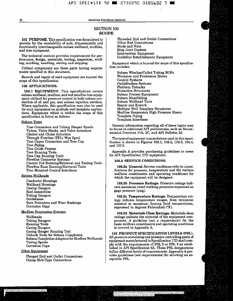
API SPECxL7D 72 m 0732270 0.503602 7 m
10 American Petroleum Institute
SECTION 100 SCOPE
101 PURPOSE. This specification was formulated to provide for the availability of safe, dimensionally and functionally interchangeable subsea wellhead, mudline, and tree equipment.
The technical content provides requirements for per- formance, design, materials, testing, inspection, weld- ing, marking, handling, storing and shipping.
Critical components are those parts having require- menta specified in this document.
Rework and repair of used equipment are beyond the scope of this specification.
102 APPLICATIONS. 102.1 EQUIPMENT. This specification covers
subsea wellhead, mudline, and wet satellite tree equip- ment utilized for pressure control in both subsea pro- duction of oil and gas, and subsea injection services. Where applicable, this specification may also be used for such equipment on multiple well template applica- tions. Equipment which is within the scope of this specification is listed as follows: -
Tree Connectors and Tubing Hanger Spools Valves, Valve Blocks, and Valve Actuators Chokes and Choke Actuators Through Flowline (TFL) Wye Spool Tree Upper Connection and Tree Cap Tree Piping Tree Guide Frames Tree Running Tools Tree Cap Running Tools Flowline Connector Systems Control Pod Runninghtetrieval and Testing Tools Flowline Base Running/Retrieval Tools Tree Mounted Control Interfaces - Conductor Housings Wellhead Housings Casing Hangers Seal Assemblies Tubing Hangers Guidebases Bore Protectors and Wear Bushings Corrosion Caps
Suspensipn Svstems Wellheads Tubing Hangers Running Tools Casing Hangers Casing Hanger Running Tod Tieback Tools for Subsea Completion Subsea Completion Adaptors for Mudline Wellheads Tubing Spools Corrosion Caps
Flanged End and Outlet Connections Clamp Hub-Type Connections
Threaded End and Outlet Connections Other End Connections Studs and Nuts Ring Joint Gaskets Intervention Equipment Guideline Establishment Equipment
Equipment which is beyond the scope of this specifica- tion includes:
Subsea Wireline/Coiled Tubing BOPS Workover and Production Risers Control Systems Guidelineless Systems Platform Tiebacks Protective Structures Subsea Process Equipment Subsea Manifolding Subsea Wellhead Tools Repair and Rework Multiple Well Template Structures Mudline Suspension High Pressure Risers Template Piping Template Interfaces
General information regarding all of these topics may be found in additional API publications, such as Recom- mended Practices 17A, 2C, and A P I Bulletin 25.
The typical equipment nomenclature used in this speci- fication is shown in Figures 102.1, 102.2, 102.3, 102.4, and 102.5.
Appendix A provides purchasing guidelines to users for A P I Specification 17D equipment.
102.2 SERVICE CONDITIONS.
102.2a General. Service conditions refer to classi- fications for pressure, temperature and the various wellbore constituents and operating conditions for which the equipment will be designed.
102.2b Pressure Ratings. Pressure ratings indi- cate maximum rated working pressures expressed as gage pressure (psig).
102.2~ Temperature Ratings. Temperature rat- ings indicate temperature ranges, from minimum ambient to maximum flowing fluid temperatures, expressed in degrees Fahrenheit ("F).
102.2d Materials Class Ratings. Materials class ratings indicate the material of the equipment com- ponents. A guideline (not a requirement) for the basic wellbore constituents and operating conditions is covered in Appendix A.
103 PRODUCT SPECIFICATION LEVELS (PSL). All pressure containing and pressure controlling parts of equipment manufactured to Specification 17D shall com- ply with the requirements of PSL 2 or PSL 3 as estab- lished in A P I Specification 6A. These PSL designations define different levels of requirements. Appendix A pro- vides guidelines (not requirements) for selecting an ac- ceptable PSL.
COPYRIGHT 2003; American Petroleum Institute
Document provided by IHS Licensee=Kellogg Borwn & Root/3262700001, User=, 09/10/2003 07:10:01 MDT Questions or comments about this message: please callthe Document Policy Group at 1-800-451-1584.
--`,,,``,```,`,`,``,`,,``,`,,`-`-`,,`,,`,`,,`---
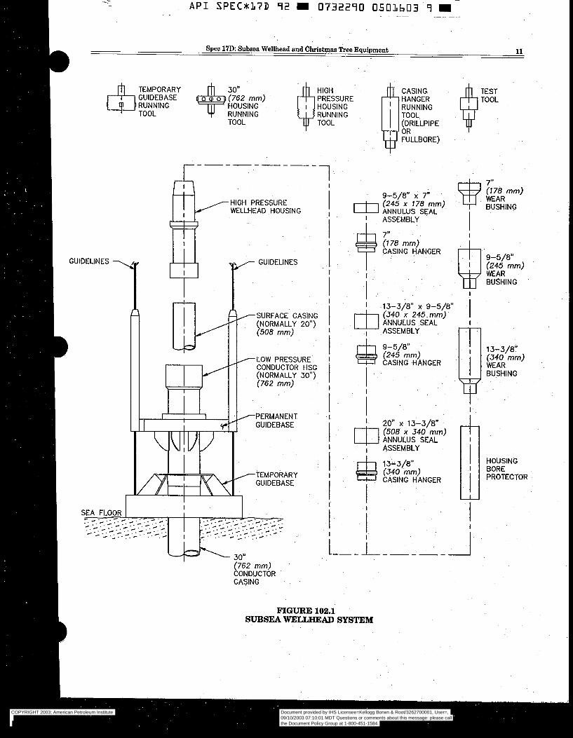
- - A P I SPEC*I( /7D 92 m 0732290 050Lb03 - 9 m I
D Spec 17D: Subsea Wellhead and Christmas Tree Equipment 11
HOUSING RUNNING TOOL
RUNNING TOOL
"-------- 7
HIGH PRESSURE WELLHEAD HOUSING
GUIDELINES
W 30" (762 mm) CONDUCTOR CASING
l
I
I
-I
CASING HANGER RUNNING TOOL
OR FULLBORE)
(DRILLPIPE
I 7" 9-5/8" X 7" v WEAR i178 mm)
BUSHING I
1 ASSEMBLY - I
I
7" (778 mm) CASING HANGER
13-3/8" X 9-5/8"
ANNULUS SEAL (340 x 245 mm)
ASSEMBLY
I
9-5/8" (245 mm) WEAR BUSHING
m I
9-5/8" (245 mm) rl l33/8" CASING HANGER
(340 mm)
BUSHING I I
I I 20" X 13-3/8"
x 340 mm)
I
HOUSING BORE PROTECTOR
I W
FIGURE 102.1 SUBSEA mLLHEAD SYSTEM
COPYRIGHT 2003; American Petroleum Institute
Document provided by IHS Licensee=Kellogg Borwn & Root/3262700001, User=, 09/10/2003 07:10:01 MDT Questions or comments about this message: please callthe Document Policy Group at 1-800-451-1584.
--`,,,``,```,`,`,``,`,,``,`,,`-`-`,,`,,`,`,,`---
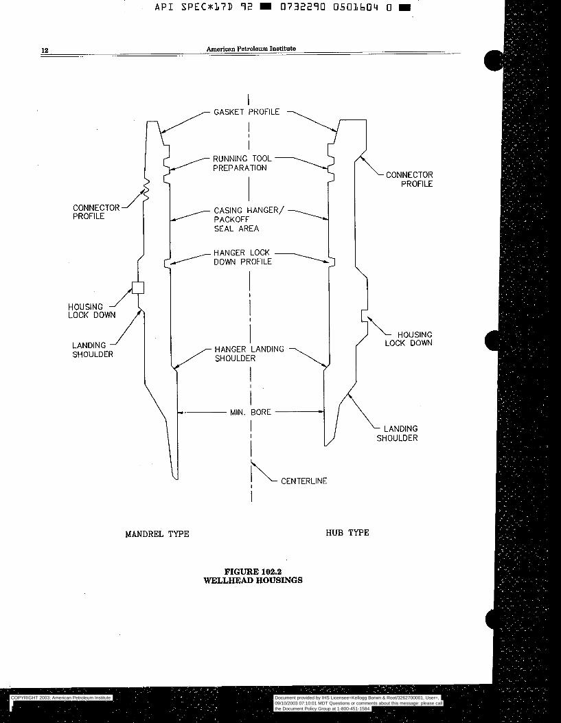
GASKET PROFILE 1
CONNECTOR 1 PROFILE
HOUSING LOCK DOWN
LANDING i SHOULDER
I I
T PACKOFF CASING HANGER/
SEAL AREA \
DOWN PROFILE HANGER LOCK
I-" I RUNNING TOOL PREPARATION 7
?- CENTERLINE
/
3 \
HANGER LANDING SHOULDER
I i
i MIN. BORE
I
?- CENTERLINE
PROFILE
I i" HOUSING
LOCK DOWN
- LANDING SHOULDER
MANDREL TYPE HUB TYPE
FIGURE 102.2 WELLHEAD HOUSINGS
COPYRIGHT 2003; American Petroleum Institute
Document provided by IHS Licensee=Kellogg Borwn & Root/3262700001, User=, 09/10/2003 07:10:01 MDT Questions or comments about this message: please callthe Document Policy Group at 1-800-451-1584.
--`,,,``,```,`,`,``,`,,``,`,,`-`-`,,`,,`,`,,`---
API SPECr17D 92 0732290 0503605 2 ' .. ~ "" ~ ~~ ~~
Spec 17D: Subsea Wellhead and Christmas Tree Equipment 13
PRODUCTION WING VALVE \ /TREE CAP
FIGURË 102.3 NON-TFL TREE
COPYRIGHT 2003; American Petroleum Institute
Document provided by IHS Licensee=Kellogg Borwn & Root/3262700001, User=, 09/10/2003 07:10:01 MDT Questions or comments about this message: please callthe Document Policy Group at 1-800-451-1584.
--`,,,``,```,`,`,``,`,,``,`,,`-`-`,,`,,`,`,,`---
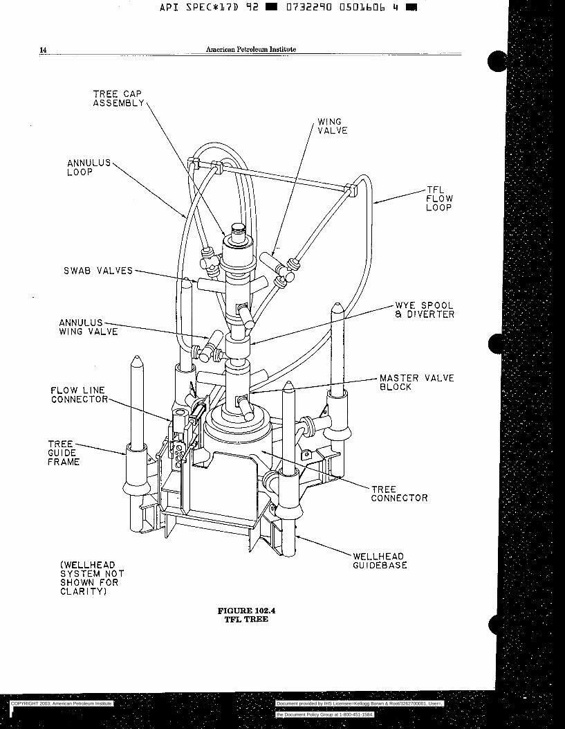
~
A P I S P E C * 1 7 D 92 I 0732290 0501606 4 E
14 American Petroleum Institute
TREE CAP
\
FIGURE 102.4 TFL TREE
COPYRIGHT 2003; American Petroleum Institute
Document provided by IHS Licensee=Kellogg Borwn & Root/3262700001, User=, 09/10/2003 07:10:01 MDT Questions or comments about this message: please callthe Document Policy Group at 1-800-451-1584.
--`,,,``,```,`,`,``,`,,``,`,,`-`-`,,`,,`,`,,`---
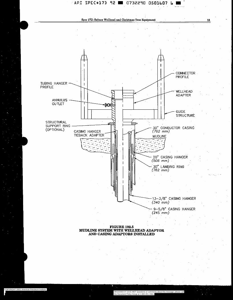
A P I S P E C * L 7 D 92 m 0732290 0503607 b li '
Spec l7D: Subsea Wellhead and Christmas Tree Equipment 16
I
m TUBING HANGER PROFILE
ANNULUS OU TLET
T PROFILE CONNECTOR
/~ WELLHEAD ADAPTER
GUIDE STRUCTURE
STRUCTURAL SUPPORT RING (OPTIONAL)
9-5/8" CASING HANGER (245 mm)
FIGURE 102.6 MUDLINE SYSTEM WITH WELLHEAD ADAPTOR
AND CASÏNG ADAPTORS INSTALLED
COPYRIGHT 2003; American Petroleum Institute
Document provided by IHS Licensee=Kellogg Borwn & Root/3262700001, User=, 09/10/2003 07:10:01 MDT Questions or comments about this message: please callthe Document Policy Group at 1-800-451-1584.
--`,,,``,```,`,`,``,`,,``,`,,`-`-`,,`,,`,`,,`---

A P I S P E C * L 7 D 92 m 0732290 0501608 8 I
16 American Petroleum Institute
Structural components and other nonpressure con- taininghontrolling parts of equipment manufactured to API Specification 17D need not comply with the require- ments of PSL 2 or PSL 3. PSL rating of assembled wellhead or tree equipment shall be determined by the lowest PSL rating of any pressure containinghontrolling component in the assembly. 104 REF'ERENCED STANDARDS. 104.1 GENERAL. This specification includes by ref-
erence, either in total or in part, the latest revision of other API, industry and government standards listed in Table 104.1 applicable at the time the order is placed, NOTE: Only those standards listed in Table 104.1 are considered part of this specification. Documents (subtier) that are referenced by those stan- dards are not considered part of this specification. 104.2 REQUIREMENTS. Requirements of other
standards included by reference in this specification are essential to the interchangeability of the equip- ment produced.
104.3 EQUIVALENT STANDARDS. Other nation- ally or internationally recognized standards shall be submitted to and approved by API for inclusion in this specification prior to their use as equivalent stan- dards. For information on submitting equivalent stan- dards for inclusion in this specification, contact the API Production Department, 2535 One Main Place, Dallas, Texas 75202-3904. 106 UNITS. A decimavinch system is the standard for
the dimensions shown in this specification. Nominal sizes will continue to be shown as fractions. This reflects current widespread industry practice. For the purposes of this specification, the fractions and their decimal equivalents are equal and interchangeable. Metric con- version rules are described in Appendix B and metric equivalents are given in the text for reference only. 106 APPENDIXES. Appendixes to this specification
shall not be considered as requirements. Unless speci- fied as a requirement in the body of this specification, appendixes are included only as guidelines or informa- tion.
TABLE 104.1 REFERENCED STANDARDS
1. ANSI B1.l: Unified Standard Inch Screw Threads .......................................................................... 2. ANSI B1.2: Gages and Gaging for Unified Inch Screw Threads ...................................................... 3. ANSI B16.11: Forged Steel Fittings, Socket-Welding and Threaded ............................................. 4. ANSI B18.2.2: Square Hex and Nuts ................................................................................................ 5. ANSI B31.3: Chemical Plant and Petroleum Refinery Piping ........................................................ 6. ANSI B31.4: Liquid Transporation Systems for Hydrocarbons, Liquid Petroleum Gas,
Anhydrous Ammonia, and Alcohols .................................................................................................. 7. ANSI B31.8: Gas Transmission and Distribution Piping Systems .................................................. 8. ANSI Y14.5M: Geometric Tolerances ............................................................................................... 9. API Spec 5CT: Casing and Tubing .................................................................................................... 10. API Spec 5D: Drill Pipe ..................................................................................................................... 11. API Std 5B: Threading, Gaging, and Thread Inspection of Casing, Tubing,
and Line Pipe Threads ...................................................................................................................... 12. API Spec 5L: Line Pipe ...................................................................................................................... 13. API Spec 6 A Wellhead and Tree Equipment ................................................................................... 14. API Spec 14D: Wellhead Surface Safety Valves and Underwater Safety Valves for
Offshore Service ................................................................................................................................ 16. API GOT: Glossary of Oilfield Production Terminology .................................................................. 16. ASME Boiler and Pressure Vessel Code, Section V, Nondestructive Testing, Article 5,
Examination Methods for Materials and Fabrication Para. T522 & T542 .................................... 17. ASME Boiler and Pressure Vessel Code, Section VIII, Division 1 .................................................
a) Part UG-101: Proof Tests to Establish Maximum Allowable Working Pressure ..................... b) Appendix 4: Rounded Indication Charts Acceptance Standard for Radiographically
Determined Rounded Indications in Welds ................................................................................ 18. ASME Section VIII, Division 2: Pressure Vessels - Alternate Rules ...........................................
a) Appendix 4: Design Based on Stress Analysis ........................................................................... b) Appendix 6: Experimental Stress Analysis ................................................................................
COPYRIGHT 2003; American Petroleum Institute
Document provided by IHS Licensee=Kellogg Borwn & Root/3262700001, User=, 09/10/2003 07:10:01 MDT Questions or comments about this message: please callthe Document Policy Group at 1-800-451-1584.
--`,,,``,```,`,`,``,`,,``,`,,`-`-`,,`,,`,`,,`---
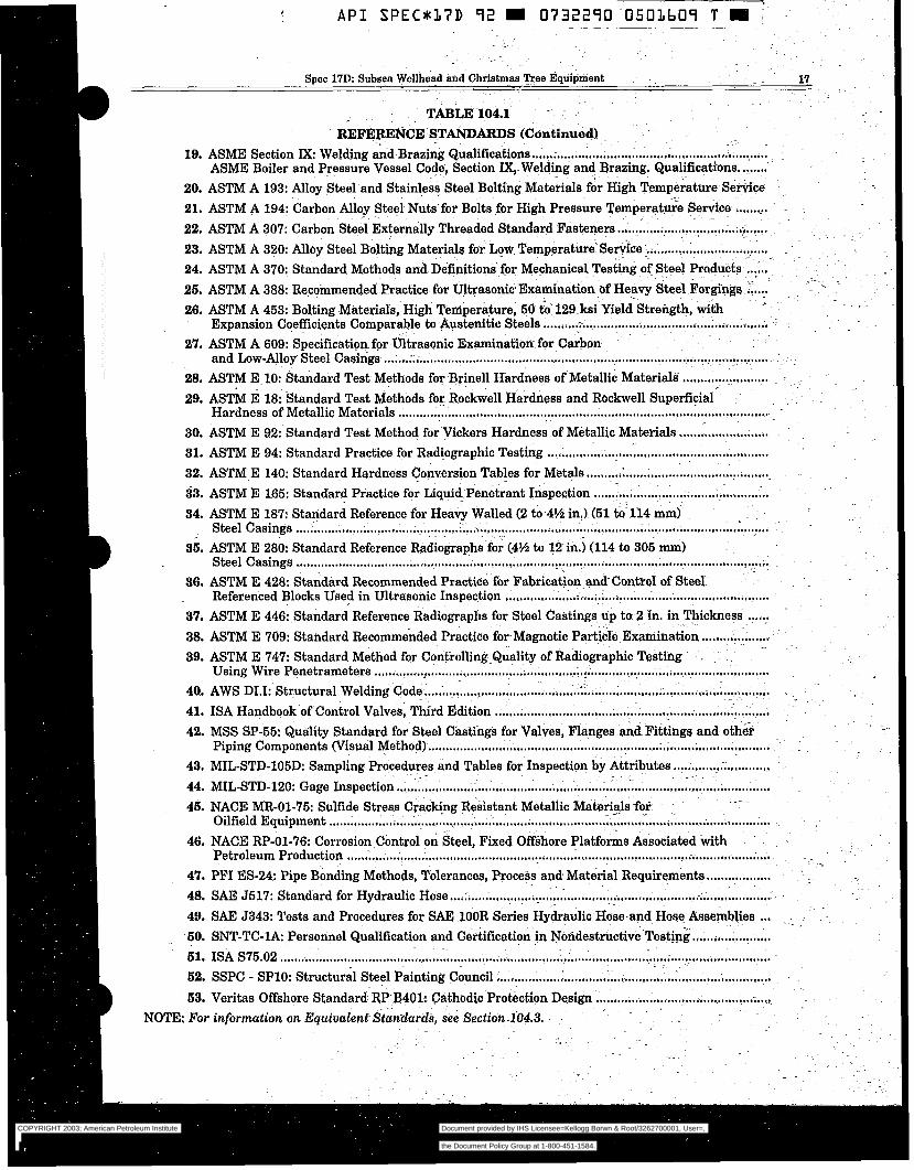
COPYRIGHT 2003; American Petroleum Institute
Document provided by IHS Licensee=Kellogg Borwn & Root/3262700001, User=, 09/10/2003 07:10:01 MDT Questions or comments about this message: please callthe Document Policy Group at 1-800-451-1584.
--`,,,``,```,`,`,``,`,,``,`,,`-`-`,,`,,`,`,,`---
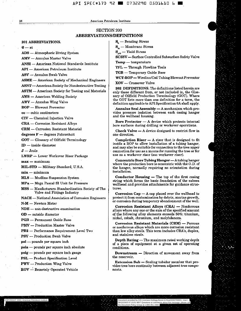
A P I S P E C * 1 7 D 9 2 E 0732270 0 5 O L b L O b E
18 American Petroleum Institute
SECTION 200 ABBREVIATIONS/DEFINITIONS
201 ABBREVIATIONS. @ - at ADS - Atmospheric Diving System AMY - Annulus Master Valve ANSI - American National Standards Institute API - American Petroleum Institute ASV - Annulus Swab Valve MME - American Society of Mechanical Engineers GSNT - American Society for Nondestructive Testing ASTM - American Society for Testing and Materials AWS - American Welding Society A W - Annulus Wing Valve BOP - Blowout Preventor cc - cubic centimeters CIV - Chemical Injection Valve C M - Corrosion Resistant Alloys CRM - Corrosion Resistant Material degrees F - degrees Fahrenheit GOT - Glossary of Oilfield Terminology ID - inside diameter J - Joule LWRP - Lower Workover Riser Package max - maximum MIL-STD - Military Standard, U.S.A. min - mínimum M I S - Mudline Suspension System MPa - Mega Pascal SI Unit for Pressure MSS - Maufacturers Standardization Society of The
NACE - National Association of Corrosion Engineers N-M - Newton Meter NDE - non-destructive examination OD - outside diameter PGB - Permanent Guide Base P W - Production Master Valve PR2 - Performance Requirement Level Two PSV - Production Swab Valve psi - pounds per square inch psia - pounds'per square inch absolute psig - pounds per square inch gauge PSL - Product Specification Level PWV - Production Wing Valve ROV i Remotely Operated Vehicle
- . . ~ " ~~ ~ ~ - . .
. .
Valve and Fittings Industry
S,, - Bending Stress Sm - Membrane Stress Syld - Yield Stress SCSSV- Surface Controlled Subsurface Safety Valve Temp - temperature TFL - Through Flowline Tools TGB - Temporary Guide Base WCT-BOP - Wireline/Coil Tubing Blowout Preventor XOV - Crossover Valve 202 DEFINITIONS. The definitions listed herein are
only those different from, or not included in, the Glos- sary of Oilfield Production Terminology (GOT). Where the GOT lists more than one definition for a term, the definition applicable to API Specification 6A shall apply.
Annulus Seal Assembly -A mechanism which pro- vides pressure isolation between each casing hanger and the wellhead housing.
Bore Protector - A device which protects internal bore surfaces during drilling or workover operations.
Check Valve - A device designed to restrict flow in one direction.
Completion Riser - A riser that is designed to fit inside a BOP to allow installation of a tubing hanger, and may also be suitable for connection to the tree upper connection for use as a means for running the tree or for use as a workover riser (see workover riser).
Concentric Bore Tubing Hanger -A tubing hanger where the production bore is concentric with the O.D. of the hanger, normally requiring no orientation during installation.
Conductor Housing - The top of the first casing string which forms the basic foundation of the subsea wellhead and provides attachments for guidance struc- tures.
Corrosion Cap - A cap placed over the wellhead to protect it from contamination by debris, marine growth, or corrosion during temporary abandonment of the well.
Corrosion Resistant Alloys ( C M ) - Nonferrous alloys where any one or the s u m of the specified amount of the following alloy elements exceeds 50%: titanium, nickel, cobalt, chromium, and molybdenum.
Corrosion Resistant Materials (CRM) - Ferrous or nonferrous alloys which are more corrosion resistant than low alloy steels. This term includes CRA's, duplex, and stainless steels.
Depth Rating - The maximum rated working depth of a piece of equipment at a given set of operating conditions.
Downstream - Direction of movement away from the reservoir.
Extension Sub - Sealing tubular member that pro- vides tree bore continuity between adjacent tree compo- nents.
COPYRIGHT 2003; American Petroleum Institute
Document provided by IHS Licensee=Kellogg Borwn & Root/3262700001, User=, 09/10/2003 07:10:01 MDT Questions or comments about this message: please callthe Document Policy Group at 1-800-451-1584.
--`,,,``,```,`,`,``,`,,``,`,,`-`-`,,`,,`,`,,`---

A P I SPEC*17D 92 m 0732290 0501611 B ~ . ~ ~ ~ ~~
Spec 17D: Subsea Wellhead andchristmas Tree Equipment 19
Fail Closed Valve - An actuated valve designed to fail to the closed position. -
Fail Open Valve -An actuated-valve designed to fail to the open position.
First End Connect2on - Thëconnectioninade a€ the initiation of the pipelaying process.
Flowline - Any pipeline connecting to the subsea tree assembly.
Flowline Connector Support Frame - A struc- tural frame which receives and supports the flowline connector and transfers flowline loads back into the wellhead structure.
Flowline Connector System -The equipment used to attach subsea pipelines and/or control umbilicals to a subsea tree. The system may include means to guide the^ end of the pipeline or umbilical into place and may include remote connection oc disconnection capabi1if.y.
Flow Loops - Piping which connects the outlet(s) of the subsea tree to the subsea flowline connection andor to other tree piping. connectiona (crossover piping, etc.).
Guide Funnel - Tapered enlargement at the end of a guidance member to provide primary guidance over another guidance member.
Guidelineless Systems - Systems which do not de- pend on the establishment of guidelines from the sea- floor to the surface vessel for guidance and alignment of subsea equipment during installation, operation, inter- vention] or retrieval.
Guidelines - Taut lines from the seafloor . to thé. surface for the purpose of guiding equipment- to the seafloor structure.
High Pressure Riser - A tubular member which extends the wellbore from the mudline tubing spool to-a surface BOP.
Inboard Tree PipiÏxg - Subsea tree piping which is upstream of the first tree wing valve.
Intervention Fixtures - Devices or features perma- nently fitted to subsea well equipment to facilitate subsea intervention tasks including] but not limited to:
~~
grasping intervention fixtures docking intervention fxtures landing intervention fixtures linear actuator intervention fixtures rotary actuator intervention fixtures fluid coupling intervention fixtures Intervention System - Means to deploy or cönvey
intervention tools to subsea well equipment to.cany out intervention tasks including:
remotely operated vehicle (ROW atmospheric diving system (ADS) diver Intervention Tools -A device or remotely operated
tool deployed by an intervention system to mate or interface with intervention fixtures.
Lower Workover Riser Package (LWRP) -A unit- ized assembly that interfaces with'the tree upper con- nection and allowa sealing of the tree production borecs). May also allow disconnect from the top connection of the
COPYRIGHT 2003; American Petroleum Institute
Document provided by IHS Licensee=Kellogg Borwn & Root/3262700001, User=, 09/10/2003 07:10:01 MDT Questions or comments about this message: please callthe Document Policy Group at 1-800-451-1584.
--`,,,``,```,`,`,``,`,,``,`,,`-`-`,,`,,`,`,,`---
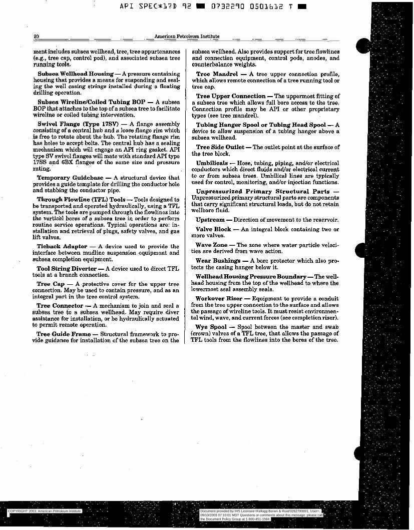
- API S P E C * I ~ D 72 m O ~ F I O O ~ O L ~ L Z T m
20 American Petroleum Institute
ment includes subsea wellhead, tree, tree appurtenances (e.g., tree cap, control pod), and associated subsea tree running tools,
Subsea Wellhead Housing - A pressure containing housing that provides a means for suspending and seal- ing the well casing strings installed during a floating drilling operation.
Subsea WirelindCoiled Tubing BOP - A subsea BOP that attaches to the top of a subsea tree to facilitate wireline or coiled tubing intervèntion.
Swivel Flange (Type 17SV) - A flange assembly consisting of a central hub and a loose flange rim which is free to rotate about the-hub. The’rotating flange rim has holes to accept bolts. The central hub has a sealing mechanism which will engage an API ring gasket. API type SV swivel flanges will mate with standard API type 17SS and 6BX flanges of the same size and pressure rating.
Temporary Guidebase - A structural device that provides a guide template for drilling the conductor hole and stabbing the conductor pipe.
Through FlowIine (TFL) TooIs -Tools designed to be transported and operated hydraulically, using a TFL system. The tools are pumped through the flowlines into the vertichl bores of a subsea tree in order to perform routine service operations. Typical operations are: in- stallation and retrieval of plugs, safety valves, and gas lift valves.
Tieback Adapter - A device used to provide the interface between mudline suspension equipment and subsea completion equipment.
Tool String Diverter - A device used to direct TFL tools at a branch connection.
Tree Cap - A protective cover for the upper tree connection. May be used to contain pressure, and as an integral part in the tree control system.
Tree Connector - A mechanism to join and seal a subsea tree to a subsea wellhead. May require diver assistance for installation, or be hydraulically actuated to permit remote operation.
Tree Guide Frame - Structural framework to pro- vide guidance for installation of the subsea tree on the
subsea wellhead. Also provides support for tree flowlines and connection equipment, control pods, anodes, and counterbalance weights.
Tree Mandrel - A tree upper connection profile, which allows remote connection of a tree running tool or tree cap.
Tree Upper Connection -The uppermost fitting of a subsea tree which allows full bore access to the tree. Connection profile may be API or other proprietary types (see tree mandrel).
Tubing Hanger Spool or Tubing Head Spool - A device to allow suspension of a tubing hanger above a subsea wellhead.
Tree Side Outlet -The outlet point at the surface of the tree block.
Umbilicals - Hose, tubing, piping, and/or electrical conductors which direct fluids and/or electrical current to or from subsea trees. Umbilical lines are typically used for control, monitoring, and/or injection functions.
Unpressurized Primary Structural Parts - Unpressurized primary structural parts are components that carry significant structural loads, but do not retain wellbore fluid.
Upstream - Direction of movement to the reservoir. Valve Block - An integral block containing two or
Wave Zone - The zone where water,particle veloci-
Wear Bushings - A bore protector which also pro- tects the casing hanger below it.
Wellhead Housing Pressure Boundary - The well- head housing from the top of the wellhead to where the lowermost seal assembly seals.
Workover Riser - Equipment to provide a conduit from the tree upper connection to the surface and allows the passage of wireline tools. It must resist environmen- tal wind, wave, and current forces (see completion riser).
Wye Spool - Spool between the master and swab (crown) valves of a TFL tree, that allows the passage of TFL tools from the flowlines into the bores of the tree.
more valves.
ties are derived from wave action.
COPYRIGHT 2003; American Petroleum Institute
Document provided by IHS Licensee=Kellogg Borwn & Root/3262700001, User=, 09/10/2003 07:10:01 MDT Questions or comments about this message: please callthe Document Policy Group at 1-800-451-1584.
--`,,,``,```,`,`,``,`,,``,`,,`-`-`,,`,,`,`,,`---

B
B
A P I SPEC*17D 72 W 0732290 0501613 1 ~. - . . ~ ~ ~~
Spec 17D: Subsea Wellhead and Christmas Tree Equipment -~ 21
SECTION 300 =
DESIGN AND PERFORMANCE.- GENERAL REQUIJ3J3MENTS 301 PERFORMANCE REQUIREMENTS.
301.1 GENERAL. Performance requirements are specific and unique to the product in the aÉ-shippëd condition. All products shall be designed toperform in accordance with Sections 300; 900, 1000, and 1100 of API Specification 17D.
301.2 PRESSURE INTEGRITY, Product designs should be capable of withsfanding rated working pres- sure at rated temperature without deformation to the extent that any other performance requirement is not met. ..
301.3 THERMAL INTEGRITY. Product designs should be capable of functioning throughout the temperature range for which the product is rated.
301.4 MATERIALS. Product designs should be ca- pable of functioning consistent with the materials class in Table 302.3 of API Specification 6A.
301.5 LEAKAGE. No observable leakage is allowed. 301.6 LOAD CAPABILITY. Product designs should
be capable of sustaining rated loads without deforma- tion to the extent that any other performance require- ment is not met. Product designs that support tubulars should be capable of supporting the ratedload without collapsing the tubulars below the drift diameter,
301.7 CYCLES. Producfdesigns should be capable of performing and operating as intended for-the num- ber of operating cycles specified by. the manufacturer.
301.8 OPERATING FÖRCE OR ?ORQUE. Prod- ucts should be designed to operate within the manufacturer's force or torque specification, as appli- cable.
. .
. _
302 SERVICE CONDITIONS. . - :
302.1 PRESSURE RATINGS, 302.la General. Pressure ratings,for API 17D
equipment shall comply with Section. 302.1~ of API Specification 6A. In addition, the effects of external loads (i.e. bending moments, tension), ambien€ hy-- drostatic loads and fatigue- shall be considered;
302.lb Subsea Trees. Pressure controlling and containing parts that comprise the subsea tree as- sembly shall be designed to operate in only the fol- lowing standard maximum rated working pressures: 5,000, 10,000, or .15,000 psi (34,5; 69,O; and 103,5 MPa).
302.1~ Tubing Hangers. Tubing hangers and as- sociated seals which could retain SCSSV control fluid pressure in the event öfa control fluid leak may alsö be designed in 7,500 and 12,500 psi (49,5 and 86,3- MPa) rated working pressures in addition to the standard pressures given in Section 302:lb;
302.ld Subsea Wellhead Equipment, The stan- dard maximum rated working pressures for subsea wellheads shall be 2,000, 5,000, 10,000, or 15,000 (13,8; 34,5; 69,O; and 103,5 MPa). Tools and internal
components suchas casing hangers may have other pressure ratings, depending on size; ~ ~
302.le MudIine Equipment. Standard rated working pressures do not^ apply to mudline -equip- men$ instead,. each-equipment- piece shall be rated for working pressure per methods given~in Section 1100'of this specification,
30Rlf Hydraulic Control Components. Hydrau- lic control components other than for SCSSY circuits shall have standard maximum- rated: working pres- sures of 1,500 or 3,000 psi (10,3.or 20,7 MPa). Hy- draulic control circuits for SCSSVs shall have stan- dard maximiun rated: working pressures equivalent to the tubing hanger given in Section 302:lc.
equipment such as running, retrieval, and test tools shall comply with manufacturer's written specifica- tions.
302.2 TËMPERATURE RATINGS. 302.2a -Standard 0perating.Ternperature Rat-
ing; Subsea equipment covered by this^ specification shall be designed and rated to operate throughout a temperature range of 35°F to-25o"F (2°C to 120°C). ..
302.213 Standard Operating Temperature Rat- ing Adjústed for Seawater Cooling. If the manu- facturer shows through analysis or testing that cer- tain equipment on subsea wellhead, mudlinë- suspension, and tree assemblies, such as valve an@. choke actuators, will not exceed .150"F when Oper- ' ated~subsea with a retained fluid at.250°F, then this equipment may be^ designed and rated to oDerate
- .
302.lg Other .Equipment. The design of other ~ ~
throughout -a kmperature range of 35°F :150"F (2°C to 65°C). - . -
. .
302.2~ Nonstandard Operating Temperahire Fkting. Ifmanufacturer's subsea equipment is to be rated to temperatures below 35'F (2°C) ör greater . ~
than 25vF (120"C), then the subsea equipment shall be tested at rated working pressure or greater per Section 307 of this specification at th6 new tempera- tures, and the newtemperature rangë shall be clearly marked on the-equipment per Section 704 of this ~ -
specification. Adjustments in temperature rating per .. Section 302.2b of this specification shall be clearly .
marked. . ~
-. 302.2d Storagemest Temperature Consider-' ations. If subsea equipment is to be- stored or tested on the surface.-at temperatures :outS.ide pf its tem- perature rating, then the manufacturer .should be contacted to determine if special storage or surface testing procedures are recommended. Manufactur- ~ .
ers shall document any such special storage or sur- face testing considerations.
302.3 MATERIALS CLASS RATINGS. - .
. 302.3a General. Shall comply with Sectìon302.3a of API Specification 6A.
COPYRIGHT 2003; American Petroleum Institute
Document provided by IHS Licensee=Kellogg Borwn & Root/3262700001, User=, 09/10/2003 07:10:01 MDT Questions or comments about this message: please callthe Document Policy Group at 1-800-451-1584.
--`,,,``,```,`,`,``,`,,``,`,,`-`-`,,`,,`,`,,`---
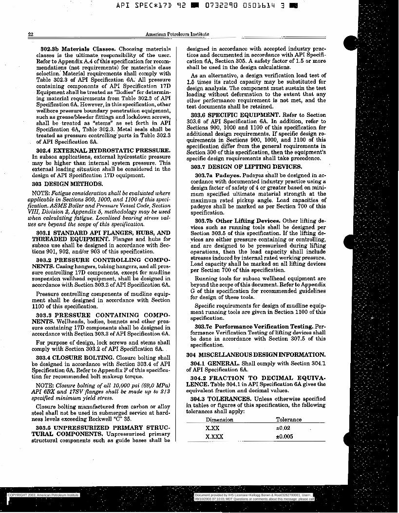
-~ I
A P I S P E C * 1 7 D 9 2 E 0732290 0501634 3 e
22 American Petroleum Institute
302.3b Materials Classes. Choosing materials classes is the ultimate responsibility of the user. Refer to Appendix A.4 of this specification for recom- mendations (not requirements) for materials class selection. Material requirements shall comply with Table 302.3 of A P I Specification 6A. All pressure containing components of API Specification 17D Equipment shall be treated as ‘Bodies” for determin- ing material requirements from Table 302.3 of A P I Specification 6A. However, in this specification, other wellbore pressure boundary penetration equipment, such as greasehleeder fittings and lockdown screws, shall be treated as %ems” as set forth in API Specification SA, Table 302.3. Metal seals shall be treated as pressure controlling’parts in Table 302.3 of API Specification 6A. 302.4 EXTERNAL HYDROSTATIC PRESSURE.
In subsea applications, external hydrostatic pressure may be higher than internal system pressure. This external loading situation shall be considered in the design of A P I Specification 17D equipment. 303 DESIGN METHODS. NOTE: Fatigue consideration shall be evaluated where
applicable in Sections 900, 1000, and 1100 of this speci- fication. ASME Boiler and Pressure Vessel Code, Section VIII, Division 2, Appendix 5, methodology may be used when calculating fätígue. Localized bearing stress val- ues are beyond the scope of this specification.
303.1 STANDARD API FLANGES; HUBS, AND THREADED EQUIPMENT. Flanges and hubs for subsea use shall be designed in accordance with Sec- tions 901, 902, and/or 903 of this specification.
NENTS. Casing hangers, tubing hangers, and all pres- sure controlling 17D components, except for mudline suspension wellhead equipment, shall be designed in accordance with Section 303.2 ofAPI Specification 6A.
Pressure controlling components of mudline equip- ment shall be designed in accordance with Section 1100 of this specification.
NENTS. Wellheads, bodies, bonnets and other pres- sure containing 17D components shall be designed in accordance with Section 303.3 ofAPI Specification 6A.
For purpose of design, lock screws and stems shall comply with Section 303.2 of A P I Specification 6A.
303.4 CLOSURE BOLTING. Closure bolting shall be designed in accordance with Section 303.4 of API Specification 6A. Refer to Appendix F of this specifica- tion for recommended bolt makeup torque.
NOTE: Closure bolting of all 10,000 psi (69,O MPa) API 6BX and 17SV flanges shall be made up to 213 specified minimum yield stress.
Closure bolting manufactured from carbon or alloy steel shall not be used in submerged service at hard- ness levels exceeding Rockwell “C” 35.
TURAL COMPONENTS. Unpressurized primary structural components such as guide bases shall be
303.2 PRESSURE CONTROLLING COMPO-
303.3 PRESSURE CONTAINING COMPO-
303.5 UNPRESSURIZED PRIMARY STRUC-
designed in accordance with accepted industry prac- tices and documented in accordance with A P I Specifi- cation 6A, Section 305. A safety factor of 1.5 or more shall be used in the design calculations.
As an alternative, a design verification load test of 1.5 times its rated capacity may be substituted for design analysis. The component must sustain the test loading without deformation to the extent that any other performance requirement is not met, and the test documents shall be retained.
303.6 SPECIFIC EQUIPMENT. Refer to Section 303.6 of API Specification 6A. In addition, refer to Sections 900, 1000 and 1100 of this specification for additional design requirements. If specific design re- quirements in Sections 900, 1000, and 1100 of this specification differ from the general requirements in Section 300 of this specification, then the equipment’s specific design requirements shall %ake precedence.
303.7 DESIGN OF LIFTING DEVICES. 303.7a Padeyes. Padeyes shall be designed in ac-
cordance with documented industry practice using a design factor of safety of 4 or greater based on mini- mum specified ultimate material strength at the maximum rated pickup angle. Load capacities of padeyes shall be marked as per Section 700 of this specification.
303.m Other Lifting Devices. Other lifting de- vices such as running tools shall be designed per Section 303.5 of this specification. If the lifting de- .vices are either pressure containing or controlling, and are designed to be pressurized during lifting operations, then the load capacity shall include stresses induced by internal rated working pressure. Load capacity shall be marked on all lifting devices per Section 700 of this specification.
Running tools for subsea wellhead equipment are beyond the scope of this document. Refer to Appendix G of this specification for recommended guidelines for design of these tools.
Specific requirements for design of mudline equip- ment running tools are given in Section 1100 of this specification. 303.7~ Performance Verification Testing. Per-
formance Verification Testing of lifting devices shall be done in accordance with Section 307.5 of this specification.
304 MISCELLANEOUS DESIGN INFORMATION. 304.1 GENERAL. Shall comply with Section 304.1
of A P I Specification 6A. 304.2 FRACTION TO DECIMAL EQUIVA-
LENCE. Table 304.1 in A P I Specification 6A gives the equivalent fraction and decimal values.
304.3 TOLERANCES. Unless otherwise specified in tables or figures of this specification, the following tolerances shall apply:
Dimension Tolerance X.XX *0.02
X.= *0.005
COPYRIGHT 2003; American Petroleum Institute
Document provided by IHS Licensee=Kellogg Borwn & Root/3262700001, User=, 09/10/2003 07:10:01 MDT Questions or comments about this message: please callthe Document Policy Group at 1-800-451-1584.
--`,,,``,```,`,`,``,`,,``,`,,`-`-`,,`,,`,`,,`---

Spec 17D: Subsea Wellhead and Christmas Tree Equipment. 23
304.4 BOLTING. Shall comply with Sections 303;4 and 304.4 of A P I Specification 6A.
304.5 m S T , VENT, INJECTION, AND GAGE CONNECTIONS. Shall comply with Section 904 of this specification, or Section 304.6 of A P I Specification 6A.
304.6 EXTERNAL CORROSION CONTRoL PROGRAM. External corrosion control for s.ubs~ea trees and wellheads should be provided by appropriate- materials selection, coating systems, and cathodic pro- tection. A corrosion control program is an ongoing activity which consists of testing, monitoring, and re- placement of spent equipment. The implementátisn of a corrosion control program is beyond the scope of this document.
304.7 COATINGS (EXTERNAL). 304.7a "he coating system and procedure used shall
comply with the written specification of the equip- ment manufacturer, the- coating manufacturer, or Appendix D of this specification.
304.m The manufacturer shall maintain, and have available for review, documentation describing the coating systems and procedures used.
304.7~ Underwater visibility should be con si de red^ when selecting coating colors, 304.8 CATHODIC PROTECTION; Cathodic pro-
tection system design requires the consideration of the external area of the equipment to be protected. I t is the responsibility of the equipment manufacturer to document and maintain the information on the wetted area of all equipment supplied according to Section 305 of this specification. This documentation shall contain the following information as a minimum:
Location and size of wetted surface area for specific
Areas where welding is prohibited. Materials of construction and coating systems ap- plied to external wetted surfaces. Control line interface locations. Flowline interfaces.
Cathodic protection design guidelines are 'contained in the following:
"Corrosion Control on Steel, Fixed Offshore Plat- forms Associated with Petroleum Production," NACE Standard RP-01-76, NACE, Houston, Texas. "Cathodic Protection Design," Veritas Offshore Stan- dard RP B401, Det Norske Veritas, Hovik, Norway.
NOTE: Some materials have demonstrateda suscep- tibility to hydrogen embrittlement when exposed to Ca- thodicprotection in seawater, Care should be exercised in the selection of materials for applications requiring high strength, corrosion resistance, and resistance -to hydrogen embrittlement. Materials which have. shown this susceptibility include martensitic stainless steels and more highly alloyed steels having yield strengths over 150,OOOpsi (1035,O MPa). Other materì& subject to this phenomenon are hardened low alloy steels,
materials.
I
COPYRIGHT 2003; American Petroleum Institute
Document provided by IHS Licensee=Kellogg Borwn & Root/3262700001, User=, 09/10/2003 07:10:01 MDT Questions or comments about this message: please callthe Document Policy Group at 1-800-451-1584.
--`,,,``,```,`,`,``,`,,``,`,,`-`-`,,`,,`,`,,`---
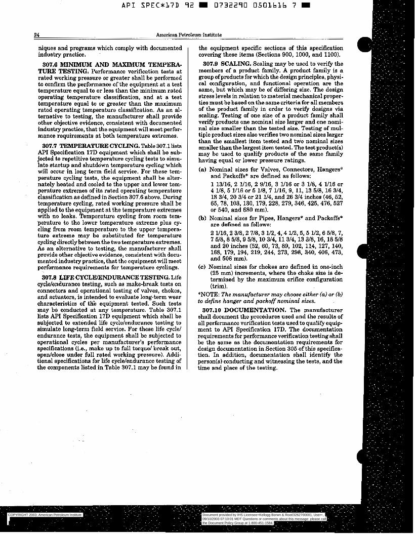
API SPEC*L7D 92 0732290 050LbLb 7 m
24 American Petroleum Institute
niques and programs which comply with documented industry practice. .
307.6 M I N I " AND MAXIMUM TEMPERA- TURE TESTING. Performance verification tests a t rated working pressure or greater shall be performed to confirm the performance of the equipment at a test temperature equal to or less than the minimum rated operating temperature classification, and at a test temperature equal to or greater than the maximum rated operating temperature classification. As an al- ternative to testing, the manufacturer shall provide other objective evidence, consistent with documented industry practice, that the equipment will meet perfor- mance requirements at both temperature extremes.
307.7 TF,"ERA"URE CYCLING. Table 307.1 lista API Specification 17D equipment which shall be sub- jected to repetitive temperature cycling tests to simu- late startup and shutdown temperature cycling which will occur in long term field service. For these tem- perature cycling tests, the equipment shall be alter- nately heated and cooled to the upper and lower tem- perature extremes of its rated operating temperature classification as defined in Section 307.6 above. During temperature cycling, rated working pressure shall be applied to the equipment a t the temperature extremes with no leaks. Temperature cycling from room tem- perature to the lower temperature extreme plus cy- cling from room temperature to the upper tempera- ture extreme may be substituted for temperature cycliyig directlybetween the two temperature extremes. As an alternative to testing, the manufacturer shall provide other objective evidence, consistent with docu- mented industry practice, that the equipment will meet performance requirements for temperature cyclings.
307.8 LIFE CYCLEXNDURANCE TESTING. Life cyclelendurance testing, such as make-break tests on connectors and operational testing of valves, chokes, and actuators, is intended to evaluate long-term wear characteristics of tKe equipment tested. Such tests may be conducted at any temperature. Table 307.1 lists API Specification 17D equipment which shall be subjected to extended life cyclelendurance testing to simulate long-term field service. For these life cycle1 endurance tests, the equipment shall be subjected to operational cycles per manufacturer's performance specifications (i.e., make up to full torque1 break out, opedclose under full rated working pressure). Addi- tional specifications for life cyclelendurance testing of the components listed in Table 307.1 may be found in
the equipment specific sections of this specification covering these items (Sections 900,1000, and 1100).
307.9 SCALING. Scaling may be used to verify the members of a product family. A product family is a group of products for which the design principles, physi- cal configuration, and functional operation are the same, but which may be of differing size. The design stress levels in relation to material mechanical proper- ties must be based on the same criteria for all members of the product family in order to verify designs via scaling. Testing of one size of a product family shall verify products one nominal size larger and one nomi- nal size smaller than the tested size. Testing of mul- tiple product sizes also verifies two nominal sizes larger than the smallest item tested and two nominal sizes smaller than the largest item tested. The test product(s) may be used to qualify products of the same family having equal or lower pressure ratings. (a) Nominal sizes for Valves, Connectors, Hangers*
and PackOffs* are defined as follows: 1 13/16, 2 1/16, 2 9116, 3 1/16 or 3 lI8, 4 1/16 or 4 1/8, 5 1/16 or 5 1/8, 7 1/16,9, 11, 13 518, 16 314, 18 314, 20 314 or 21 1/4, and 26 314 inches (46, 52, 65,78,103,130,179,228,279,346,425,476,527 or 540, and 680 mm).
(b) Nominal sizes for Pipes, Hangers* and PackOffs* are defined as follows: 2 1/16,2 3/8,2 718,3 112,4,4 ll2, 5 ,5 1/2,6 518, 7, 7 5/8,8 518,9 518, 10 314, 11 314, 13 318, 16, 18 518 and 20 inches (52, 60, 73, 89, 102, 114, 127, 140, 168, 179, 194, 219, 244, 273, 298, 340, 406, 473, and 508 mm).
(c) Nominal sizes for chokes are defined in one-inch (25 mm) increments, where the choke size is de- termined by the maximum orifice configuration (trim).
*NOTE: The manufacturer may choose either (a) or (b) to define hanger and packoff nominal sizes.
307.10 DOCUMENTATION. The manufacturer shall document the procedures used and the results of all performance verification tests used to qualify equip- ment to API Specification 17D. The documentation requirements for performance verification testing shall be the same as the documentation requirements for design documentation in Section 305 of this specifica- tion, In addition, documentation shall identify the person(s) conducting and witnessing the tests, and the time and place of the testing.
COPYRIGHT 2003; American Petroleum Institute
Document provided by IHS Licensee=Kellogg Borwn & Root/3262700001, User=, 09/10/2003 07:10:01 MDT Questions or comments about this message: please callthe Document Policy Group at 1-800-451-1584.
--`,,,``,```,`,`,``,`,,``,`,,`-`-`,,`,,`,`,,`---
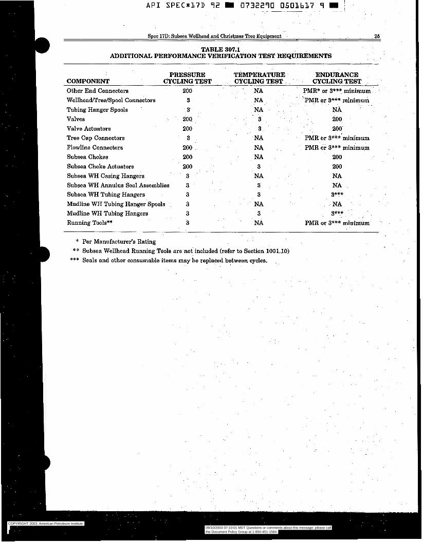
A P I SPECg17D 92 m 0732290 O501617 9 m j ~ ~ - ~ ~ _ _ _ _ ~ ~~ - ,
B Spec 17D: Subsea Wellhead and Christmas "T? Equipment 26 .~
TABLE 307.1 - ADDITIONAL PERFORMANCE VERIFICATION TEST REQUIREMENTS
PRESSURE TEMPERATURE CYCLING TEST
ENDURANCE CYCLING TEST. ~ CYCLING TEST COMPONENT
Other End Connectors 200 - " NA PMR* or 3*** minimum WellheadPTreelSpool Connectors 3 Tubing Hanger Spools 3 Valves 200 Valve Actuators 200
n e e Cap Connectors 3 Flowline Connectors 200 Subsea Chokes 200
Subsea Choke Actuators 200 Subsea WH Casing Hangers 3 Subsea WH Annulus Seal Assemblies 3 Subsea WH Tubing Hangers 3 Mudline WH Tubing Hanger Spools . 3 Mudline WH Tubing Hangers 3 Running Tools** 3
* Per Manufacturer's Rating
NA -PMR or 3*** minimum NA NA
3 200
3 200 NA PMR or 3***.minimum NA PMR or 3*** minimum NA 200 3 200
NA NA 3 NA 3 3***
NA NA . .~
3 3*** NA PMR or 3*** minimum
~~
B ** Subsea Wellhead Running Tools are not included (refer to Section 1001.10) *** Seals and other consumable items may be replaced between cycles. ~. ,
COPYRIGHT 2003; American Petroleum Institute
Document provided by IHS Licensee=Kellogg Borwn & Root/3262700001, User=, 09/10/2003 07:10:01 MDT Questions or comments about this message: please callthe Document Policy Group at 1-800-451-1584.
--`,,,``,```,`,`,``,`,,``,`,,`-`-`,,`,,`,`,,`---
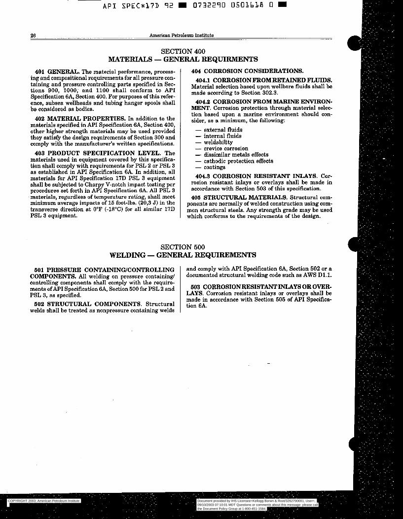
26 American Petroleum Institute
SECTION 400 MATERIALS - GENERAL REQUIRMENTS
401 GENERAL, The material performance, process- 404 CORROSION CONSIDERATIONS. ing and compositional requirements for all pressure con- 404.1 CORROSION FROM RETAINED FLUIDS. taining and pressure controlling parts specified in Sec- Material selection based upon wellbore fluids shall be tions 900, 1000, and 1100 shall conform t o API Specification 6A, Section 400, For purposes of this refer- ence, subsea wellheads and tubing hanger spools shall 404.2 CORROSION FROM MARINE ENVIRON- be considered as bodies. l K E N T . Corrosion protection through material selec-
tion based upon a marine environment should con-
materials specified in API Specification 6A, Section 400, other higher strength materials may be used provided - external fluids they satisfy the design requirements of Section 300 and - internal fluids comply with the manufacturer's written specifications. - weldability
403 PRODUCT SPECIFICATION LEVEL. The - crevice corrosion
materials used in equipment covered by this specifica- - dissimilar metals effects
tion shall comply with requirements for PSL 2 or PSL 3 - cathodic protection effects
as established in API Specification 6A. In addition, all - coatings
materials for API Specification 17D PSL 3 equipment 404.3 CORROSION RESISTANT INLAYS. Cor- shall be subjected to Charpy V-notch impact testing per IWkJn resistant inlays Or overlays shall be Xnade in
materials, regardless of temperature rating, shall meet 405 S'I'RUC- MATERIALS. Structural corn- minimum average impacts of 15 foot-lbs. (20,3 J) in the ponents are normally of welded construction using com- transverse direction at 0°F (-18°C) for all similar 17D mon structural steels. Any strength grade may be used
made to Section 302+3.
402 MATERIAL PROPERTIES. In addition to the . as a minimurn, the following:
set forth in A ~ I Specification GA. ~1 p s ~ 3 accordance with Section 503 of this specification.
PSL 3 equipment. which conforms to the requirements of the design.
controlling components shall-comply with the require- ments ofAPI Specification 6A, Section 500 for PSL 2 and 603 CoRRoS1oNRESISTANT~ys OR OVER- PSL 3, as specified. LAYS. Corrosion resistant inlays or overlays shall be
made in accordance with Section 505 of API Specifica-
welds shall be treated as nonpressure containing welds 602 STRUCTURAL COMPONENTS. Structural tion GA.
COPYRIGHT 2003; American Petroleum Institute
Document provided by IHS Licensee=Kellogg Borwn & Root/3262700001, User=, 09/10/2003 07:10:01 MDT Questions or comments about this message: please callthe Document Policy Group at 1-800-451-1584.
--`,,,``,```,`,`,``,`,,``,`,,`-`-`,,`,,`,`,,`---
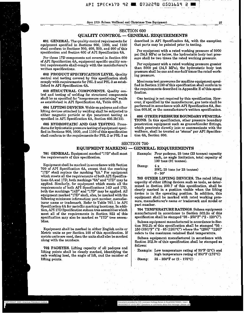
Spec 17D: Subsea Wellhead and Christmas Tree Equipment 21
SECTION 600 QUALITY CONTROL -
601 GENERAL. The quality control requirements for equipment specified in Sections 900, 1000, anä 1100 shall conform to Sections 300, 400, 500, and 600 of this specification and Section 600 of API Specification 6A.
For those 17D components not covered in Section 600 of API Specification 6A, equipment specific quality con- trol requirements shall comply with the manufacturer’s written specifications.
602 PRODUCT SPECIFICATION LEVEL. Quality control and testing covered by this specification shall comply with requirements for PSL 2 and PSL 3 as estab- lished in API Specification 6A.
603 STRUCTURAL COMPONENTS. Quality con- trol and testing of welding for structural components shall be as specified for “nonpressure containing“ welds as established in API Specification 6A, Table 605.2.
604 LIFTING DEVICES. Welds on padeyes and other lifting devices attached by welding shall be subjected to either magnetic particle or dye penetrant testing as specified in API Specification 6A, Section 605.2b(12).
605 HYDROSTATIC AND GAS TESTING. Proce- dures for hydrostatic pressure testing of equipment speci- fied in Sections 900,1000, and 1100 of this specification shall conform to the requirements for PSL 2 or PSL 3 as
NERAL REQUIREMENTS described in API Specification 6A, with the exception - that parts may be painted prior to testing.
For equipment with a rated working pressure of 5000 psi (34,5 MPa) or below, the hydrostatic body test pres- sure shall be two times the rated working pressure.
For equipment with a rated working pressure greater than 5000 psi (34,5 m a ) , the hydrostatic body test pressure shall be one and one-half times the rated work- ing pressure.
Maximum test pressures for mudline equipment speci- fied in Section 1100 of this specification shall conform to the requirements described in Appendix E of this speci- fication.
Gas testing is not required by this specifkation. How- ever, if specified by th’e manufacturer, gas tests shall be performed in accordance with API Specification 6A, Sec- tion 605.9f, or the manufacturer’s written specification.
606 OTHERPRESSURE BOUNDARY PENETFU- TIONS. In this specification, other pressure boundary penetration equipment such as greasehleeder fittings, which penetrate directly into or communicate with the wellbore, shall be treated as “stems” per API Specifica- tion 6A, Section 600.
SECTION 700- EQUIPMENT MARKING - GENERAL REQUIREMENTS
701 GENERAL. Equipment marked “17D” shall meet the requirements of this specification.
Equipment shall be marked in accordance with Section 700 of API Specification 6A, except that the marking “17D” shall replace the marking “6A.” For equipment which meets all the requirements of both API Specifica- tions 6A and 17D, both markings “6A” and “17D” may be applied. Similarly, for equipment which meets all the requirements of both API Specifications 14D and 17D, both the markings “14D” and “17D” may be applied. All equipment marked “17D” shall, also, be marked with the following minimum information: part number, manufac- turer name or trademark. Refer to Table 701.1 in API Specification 6A for metallic marking locations. In addi- tion, MI 17D Specification subsea tree assemblies which meet all of the requirements in Section 922 of this specification may also be marked as “17D” tree assem- blies.
Equipment shall be marked in either English units or Metric units as per Section 105 of this specification. If metric units are used, then the units shall also be marked along with the numbers.
702 PADEYES. Lifting capacity of all padeyes and lifting points shall be clearly marked, identifying the safe working load, the angle of lift, and the number of lifting points.
Example: Four padeyes, 25 tons (23 tonnes) capacity each, no angle limitation, total capacity of 100 tons (91 tonnes).
SWL 25 tons (or 23 tonnes) stamp: 4 x
O - 90” 703 OTHER LIFTING DEVICES, The rated lifting
capacity of other lifting devices such as tools, as deter- mined in Section 303.7 of this specification, shall be clearly marked in a position visible when the lifting device is in the operating position. In addition, this equipment shall be marked with rated working pres- sure, manufacturer’s name or trademark and model or part number.
704 TEMPERATURE RATINGS. Subsea equipment manufactured in accordance to Section 302.2a of this specification shall be stamped “35 - 250°F (“2 - 120°C”).
Subsea equipment manufactured in accordance to Sec- tion 302.2b of this specification shall be stamped “35 - 150 (250)”F” (“2 - 65 (120)OC”) where the “(250)” “(120)” refers to the maximum retained fluid temperature.
Subsea equipment manufactured in accordance with Section 302.3~ of this specification shall be stamped as follows:
Example: Low temperature rating of 35°F (2°C) and high temperature rating of 350°F (175°C)
- Stamp: 35 - 350°F or (2 - 175°C)
COPYRIGHT 2003; American Petroleum Institute
Document provided by IHS Licensee=Kellogg Borwn & Root/3262700001, User=, 09/10/2003 07:10:01 MDT Questions or comments about this message: please callthe Document Policy Group at 1-800-451-1584.
--`,,,``,```,`,`,``,`,,``,`,,`-`-`,,`,,`,`,,`---
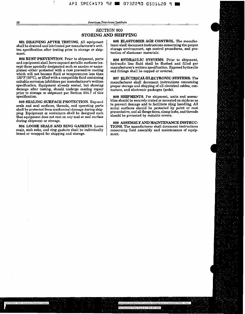
COPYRIGHT 2003; American Petroleum Institute
Document provided by IHS Licensee=Kellogg Borwn & Root/3262700001, User=, 09/10/2003 07:10:01 MDT Questions or comments about this message: please callthe Document Policy Group at 1-800-451-1584.
--`,,,``,```,`,`,``,`,,``,`,,`-`-`,,`,,`,`,,`---
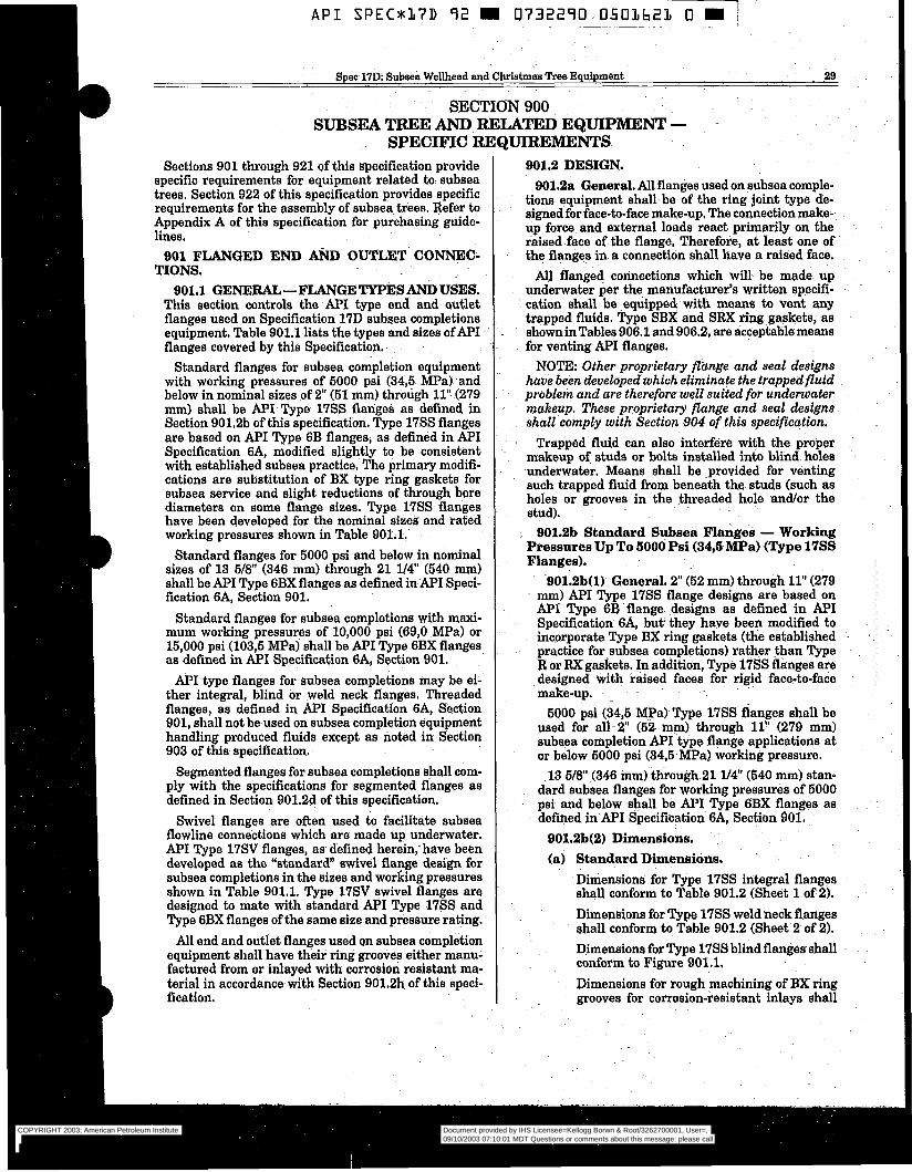
API SPEC*17D 92 m 0732290 0501621 O W j ~~~ .~ ~~ .
Spec 17D: Subsea Wellhead and%h&tmaa Tree Equipment 29
SECTION 900
SPECIFIC REQUIREMENTS SUBSEA TREE AND RELATED ËQUIPMËNT -
Sections 901 through 921 of this specification provide specific requirements for equipment related to subsea trees, Section 922 of this specification provides specific requirements for the assembly of subsea trees. Refer to Appendix A of this specification for purchasing guide- lines.
901 FLANGED END ARD OUTLET CONNEC- TIONS.
901.1 GENERAL-FLANGETYPESANDUSES. This section controls the API type end and outlet flanges used on Specification 17D subsea completions equipment. Table 901.1 lists the types and sizes of API flanges covered by this Specification.
Standard flanges for subsea completion equipment with working pressures of 5000 psi (34$ MPa) and below in nominal sizes of 2" (51 mm) through 11" (279 mm) shall be API Type 1755 flanges as defined in Section 901.2b ofthis specification. Type 17SS flanges are based on API "ype 6B flanges, as defined i n API Specification 6A, modified slightly to be consistent with established subsea practice, The primary modifi- cations are substitution of BX type ring gaskets for subsea service and slight reductions of through bore diameters on some flange sizes. Type 17SS flanges have been developed for the nominal sizeá and rated working pressures shown in Table 901.1.
Standard flanges for 5000 psi and below in nominal sizes of 13 5/8" (346 mm) through 21 114" (540 mm) shall be API Type 6BX flanges as defined in API Speci- fication 6A, Section 901.
Standard flanges for subsea completions with maxi- mum working pressures of 10,000 psi (69,O MPa) or 15,000 psi (103,5 MPa) shall be API Type 6BX flanges as defined in API Specification 6A, Section 901.
API type flanges for subsea completions may be ei- ther integral, blind or weld neck flanges. Threaded flanges, as defined in API Specification 6A, Section 901, shall not be used on subsea completion equipment handling produced fluids except as noted in Section 903 of this specification.
Segmented flanges for subsea completions shall com- ply with the specifications for segmented flanges as defined in Section 901.2d of this specification.
Swivel flanges are often used to facilitate subsea flowline connections which are made up underwater. API Type 17SV flanges, as defined herein, have been developed as the "standard" swivel flange design for subsea completions in the sizes and working pressures shown in Table 901.1. Type 17SV swivel flanges are designed to mate with standard API Type 17SS and Type 6BX flanges of the same size and pressure rating.
All end and outlet flanges used on subsea completion equipment shall have their ring grooves either manu- factured from or inlayed with corrosion resistant ma- terial in accordance-with Section 901.2h of this speci- fication.
901.2 DESIGN. 901.2a General, All flanges used on subsea comple-
tions equipment shall be of the ring joint type de- signed for face-to-face make-up, The co~nnection make- up force and external loads react primarily on the raised face of the flange, Therefore, a t least one of the flanges in a connection shall have a raised face.
All flanged connections which will be made up underwater per the manufacturer's written specifi- cation shall be -equipped with means to vent any trapped fluids. Type SBX and SRX ring gaskets, as showninTables 906.1 and 906.2, are acceptable means for venting API flanges.
NOTE: Other proprietary fldnge and seal designs have been developed which eliminate the trappedfluid problem and are therefore well suited for underwater makeup. These proprietary flange and seal designs shall comply with Section 904 of this specification.
Trapped fluid can also interfere with the proper makeup of studs or bolts installed into blind holes underwater. Means shall be .provided for venting such trapped fluid from beneath the studs (such as holes or grooves in the threaded. hole andlor the stud).
901.2b Standard Subsea Flanges - Working Pressures Up Tod000 Psi (34,6 MPa) (Type 17SS Flanges),
901.2b(l) General. 2" (52 mm) through 11" (279- mm) API Type 17SS flange designs are based on API Type 6B flange designs as defined in API Specification 6A, but they have been modified to incorporate Type BX ring gaskets (the established practice for.subsea completions) rather than Type R or RX gaskets. In addition, Type 1765 flanges are designed with raised faces for rigid face-to-face make-up.
5000 psi (34,5 MPa) Type 17SS flanges shall be used for all- 2" (62 mm) through 11" (279 mm) subaea completion MI-type flange applications at or below 5000 psi (34.5 MPa) working pressure.
13 5/8' (346 mm) through21 l/4 (540 mm) stan- dard subsea flanges for working pressures of 5000 psi and below shall be API Type 6BX flanges as defined in API Specification 6A, Section 901.
901.2b(2) Dimensions. (a) Standard Dimensions.
Dimensions for Type 1755 integral flanges shall conform to Table 901.2 (Sheet 1 of 2). Dimensions for Type 17SS weld neck flanges shall conform to Table 901.2 (Sheet 2 of 2). Dimensions for Type 17SS blind flanges shall conform to Figure 901.1, Dimensions for rough machining of BX ring grooves for corrosion-resistant inlays shall
COPYRIGHT 2003; American Petroleum Institute
Document provided by IHS Licensee=Kellogg Borwn & Root/3262700001, User=, 09/10/2003 07:10:01 MDT Questions or comments about this message: please callthe Document Policy Group at 1-800-451-1584.
--`,,,``,```,`,`,``,`,,``,`,,`-`-`,,`,,`,`,,`---
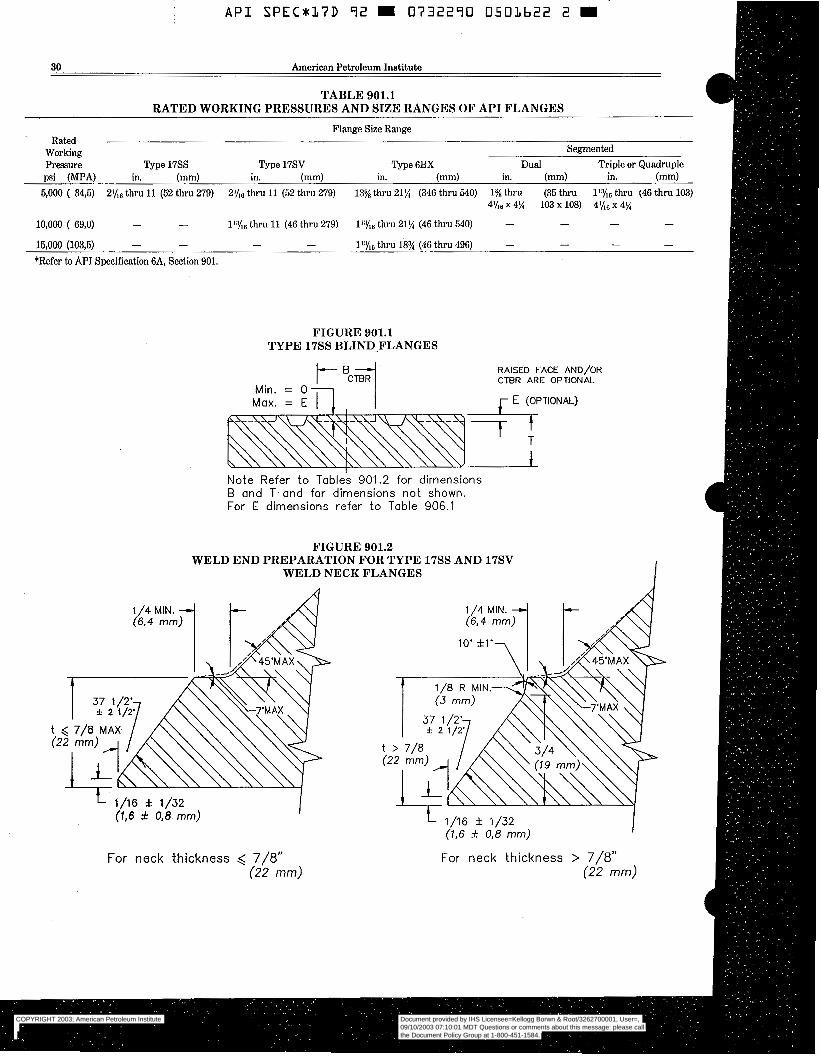
A P I SPECU17D 92 0732290 0501622 2 m
30 American Petroleum Institute
TABLE 901.1 RATED WORKING PRESSURES AND SIZE RANGES OF API FLANGES
Flange Size Range Rated
Working Pressure Type 17SS Type 17SV Type 6BX Dual Triple or Quadruple
psi (MPA) in. (mm) in. (mm) in. (mm) in. (mm) in. (mm) 6,000 ( 34,5) ZY,, thru 11 (52 thru 279) 2Yl6 thru 11 (52 thru 279) 13% thru 21% (346 thru 540) 1% thru (35 thru 11% thru (46 thru 103)
Segmented
4'116 x 4% 103 X 108) 4x6 X 4%
10,000 ( 69,O) - - l':yl6 thru 11 (46 thru 279) thru 21% (46 thru 540) - - - -
16,000 (103,6) - - *Refer to API Specification 6A, Section 901.
- - 1':%, thru 18% (46 thru 496) - - - -
FIGURE 901.1 TYPE 17SS BLIND-FLANGES
Max. = E n ,
Min. = O
RAISED FACE AND/OR CTBR ARE OPTIONAL
r E (OPTIONAL)
Note Refer to Tables 901.2 for d imensions B and T and for dimensions not shown. For E dimensions refer to Table 906.1
FIGURE 901.2 WELD END PREPARATION FOR TYPE 17SS AND 17SV
WELD NECK FLANGES
L 1/16 f 1/32 (1,6 f 0.8 mm) I
For neck thickness ,< 7/8" (22 mm)
1/16 f 1/32 (1,6 f 0,8 mm)
For neck thickness > 7/8" (22 mm)
COPYRIGHT 2003; American Petroleum Institute
Document provided by IHS Licensee=Kellogg Borwn & Root/3262700001, User=, 09/10/2003 07:10:01 MDT Questions or comments about this message: please callthe Document Policy Group at 1-800-451-1584.
--`,,,``,```,`,`,``,`,,``,`,,`-`-`,,`,,`,`,,`---
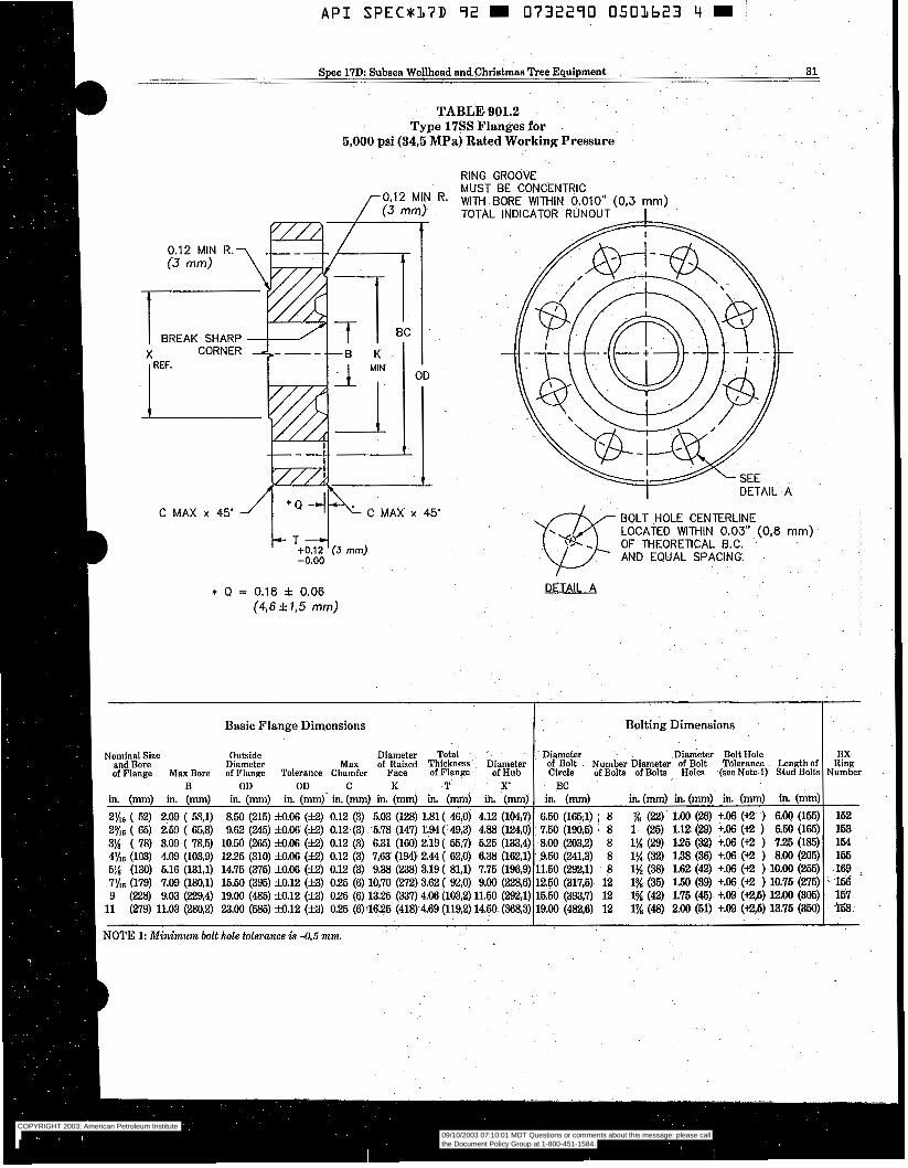
D
B
Spec 17D Subsea Wellhead and Christmas Tree Equipment 31 ~~
TABLE 901.2 Type 17SS Flanges for
5,000 psi (34,5 MPa) Rated Working Pressure
BREAK SHARP
C MAX x 45' /1 * Q 4k C MAX x 45'
RING GROOVE MUST BE CONCENTRIC NTH BORE WTHIN 0.010" (0,3 mm) TOTAL INDICATOR RUNOUT I
DETAIL A
BOLT HOLE CENTERLINE LOCATED WITHIN 0.03" (0,8 mm) OF THEORETICAL B.C. AND EQUAL SPACING.
I
* Q = 0.18 f 0.06 DETAIL 4 (46 f 1.5 mm)
Nominal Size
of Flange Nax Bore and Bore
in. (mm) in. (mm) B
2% ( 52) 2-09 ( 6%1) 2% ( 65) 2.59 ( 658 3% ( 78) 3.09 ( 78,5) 41/16 (103) 4.09 (103,9) 6% (130) 5.16 (131,l)
9 (228) 9.03 (229,4) 11 (279) 11.03 (ZS0,Z)
NOTE 1: Minimum bolt
7yf6 (179) 7.09 (18031)
I Basic Flange Dimensions Bolting Dimensions
Outside Diameter Max of Raised Thickness Diameter of Bolt Number Diameter of Bolt Tolerance Lengthof of Flange Tolerance Chamfer Face of Flange of Hub Circle of Bolts ofBolts Holes (seeNote1r StudBoltr
Diameter Total Diameter Diameter Bolt Hole
OD OD C K T x BC in. (mm) in. (mm)' in. (mm) in. (mm) in. (mmj in. (mm) in. (mm) 850 (215) fo.06 (B) 0.12 (3) 5.03 (128) 1.81( &,O) 4.12 (104i7) 6.50 (165,l) 8 9.62 (245) fo.06 (B) 0.12 (3) 5.78 (147) 1.94( 49,3) 4.88 (124.0) 7.50 (190,6) . 8 10.50 (265) M.06 (E!) 0.12 (3) 6.31 (160) 2.19 ( 55,7) 525 (133,4) 8.00 (2032) 8 1225 (310) 3.06 (f2) 0.12 (3) 7,63 (194) 2.44 ( 62,O) 6.38 (162,l) 9.60 (243) 8 14.75 (375) 33.06 (B) 0.12 (3) 9.38 (238) 3.19 ( 81,l) 7.75 (196,9) 11.50 (292,l) 8 15.50 (395) 33.12 (23) 025 (6) 10,70 (272) 3.62( 92,O) 9.00 (2286) 12.50 (317,5) 12 19.00 (485) fo.12 (B) 025 (6) 13.25 (337) 4.06 (103,2) 11.50 (292'1) 15.50 (393,7) 12 23.00 (585) 33.12 (k3) 025 (6) 9625 (418) 4.69 (119,2) 14.50 (-3) 19.00 (482,6) 12
hole tolerance is -45 mm.
in.(mm) in(mm) in. (mm) in. (mm) M (22- 1.00 (26) +.O6 (+2 ) 6.00 (155) 1 (25) 1.12 (29) +.O6 (+2 ) 6.60 (165) 1% (29) 125 (32) +.O6 (+2 ) 7.25 (1%) 1% (32) 1.38 (36) +.O6 (+2 ) a00 (205) 1% (38) 1.62 (42) +.O6 (+2 ) 10.00 (265) 1% (35) 1.60 (39) +.O6 (+2 ) 10.76 (276) 1% (42) 1.75 (46) +.O9 (+2,6) 12.00 (306) 1% (48) 2.00 (61) +.O9 (+2,6) 1876 (360)
COPYRIGHT 2003; American Petroleum Institute
Document provided by IHS Licensee=Kellogg Borwn & Root/3262700001, User=, 09/10/2003 07:10:01 MDT Questions or comments about this message: please callthe Document Policy Group at 1-800-451-1584.
--`,,,``,```,`,`,``,`,,``,`,,`-`-`,,`,,`,`,,`---
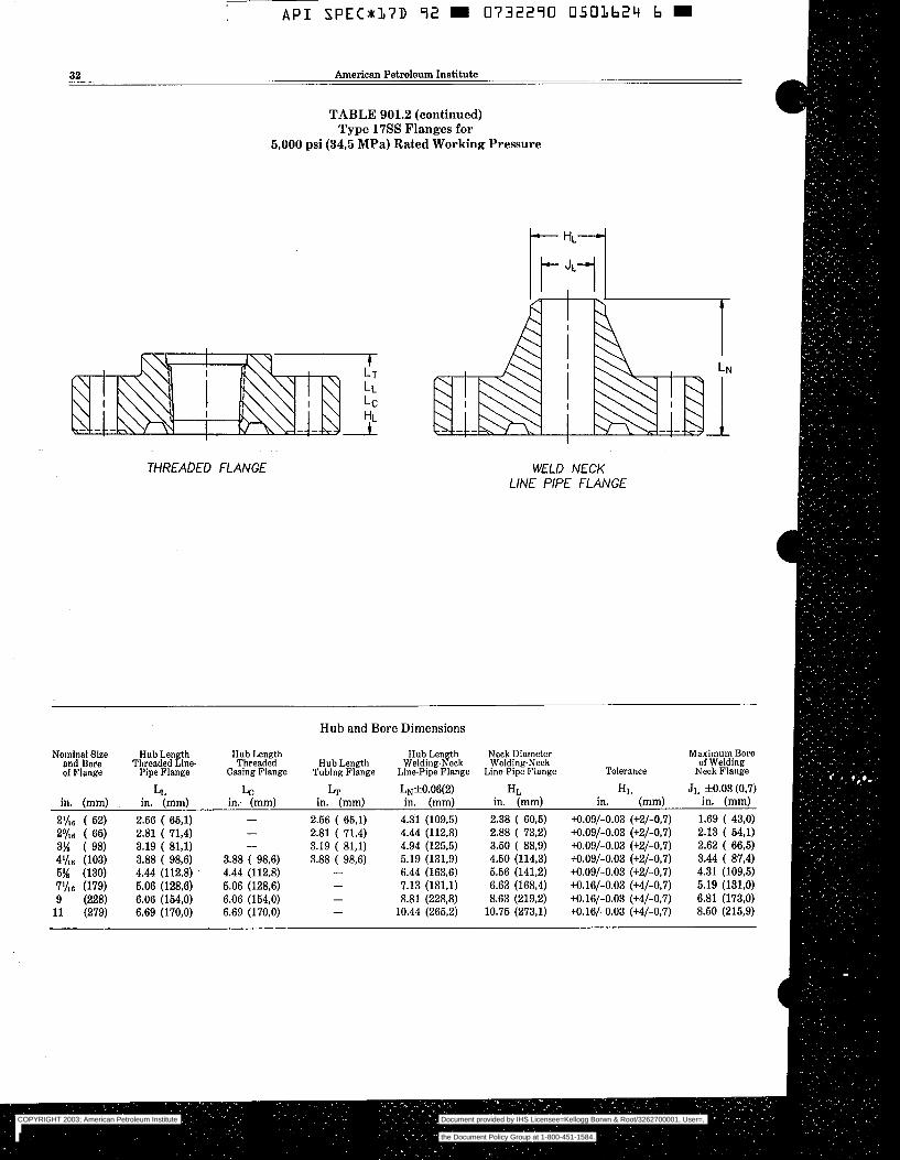
A P I SPEC*17D 92 0732290 0503624 b
32 American Petroleum Institute
TABLE 901.2 (continued) Type 1755 Flanges for
5,000 psi (34,5 MPa) Rated Working Pressure
WELD NECK LINE PIPE FLANGE
Hub and Bore Dimensions
Nominal Size Hub Length Hub Length Hub Length Neck Diameter and Bore Threaded L m e Threaded Hub Length Welding-Neck Welding-Neck
Maximum Bore
of Flange Pipe Flange Casing Flange Tubing Flange LinePipe Flange LinePipe Flange Tolerance of Welding
Neck Flange
LL in. (mm)
2.56 ( 65,l) 2.81 ( 71,4) 3.19 ( 81,l) 3.88 ( 98,6) 4.44 (112,8) 5.06 (128,6) 6.06 (154,O) 6.69 (170,O)
LC in: (mm) -
3.88 ( 98,6) 4.44 (112.8) 5.06 (128,6) 6.06 (154,O) 6.69 (170,O)
-
Lr in. (mm)
2.56 ( 65,l) 2.81 ( 71,4) 3.19 ( 81.1) 3.88 ( 98.6)
L~f0.06(2) in. (mm)
4.31 (109.5) 4.44 (112,8) 4.94 (125.5) 5.19 (131.9) 6.44 (163,6) 7.13 (181.1) 8.81 (228,8)
10.44 (265,2)
H L in. (mm)
2.38 ( 60,5) 2.88 ( 73,2) 3.50 ( 88,9) 4.50 (114.3) 5.56 (141,2) 6.63 (168,4) 8.63 (219,2)
10.75 (273,l)
H L in. (mm)
+0.09/-0.03 (+2/-0,7) +0.09/-0.03 (+2/-0,7) +0.09/-0.03 (+2/-0,7) +0.09/-0.03 (+2/-0.7) +0.09/-0.03 (+2/-0.7) +0.16/-0.03 (+4/-0,7) +0.16/-0.03 (+4/-0,7) +0.16/-0.03 (+4/-0,7)
JL f0.03 (0.7) in. (mm)
1.69 ( 43,O) 2.13 ( 54,l) 2.62 ( 66.5) 3.44 87,4) 4.31 (109,5) 5.19 (131,O) 6.81 (173,O) 8.50 (215,9)
COPYRIGHT 2003; American Petroleum Institute
Document provided by IHS Licensee=Kellogg Borwn & Root/3262700001, User=, 09/10/2003 07:10:01 MDT Questions or comments about this message: please callthe Document Policy Group at 1-800-451-1584.
--`,,,``,```,`,`,``,`,,``,`,,`-`-`,,`,,`,`,,`---
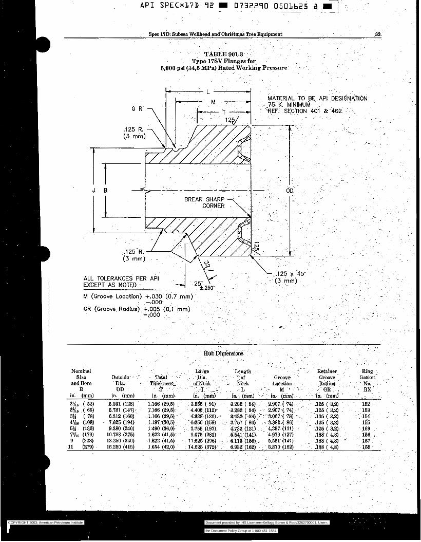
~.
"
TABLE 901.3 ~ - ~~
~- ~ Type 17SV Flanges for" ~. - .
6,000-psi (34,6 MPa) Rated Working Pressure = ~ ~
- .
. .
T J
MATERIAL TO BE API DESIGNATION- : :- 75 K. MINIMUM -.
":REF- SECTION 401 &402 -~. :~~-
COPYRIGHT 2003; American Petroleum Institute
Document provided by IHS Licensee=Kellogg Borwn & Root/3262700001, User=, 09/10/2003 07:10:01 MDT Questions or comments about this message: please callthe Document Policy Group at 1-800-451-1584.
--`,,,``,```,`,`,``,`,,``,`,,`-`-`,,`,,`,`,,`---
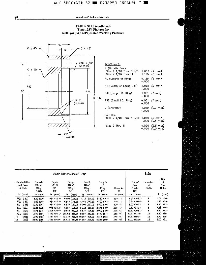
A P I S P E C x 1 7 D 72 0732290 0501b2b T
34 American Petroleum Institute
TABLE 901.3 (continued) Type 17SV Flanges for
5,000 psi (343 MPa) Rated Working Pressure
cx4yY c x 45'
TOLERANCE: R (Outside Dia.)
Size 2 1/16 Thru 5 1/8 f.062 (2 mm) Size 7 1/16 Thru 11 f .125 (3 mm)
RL (Length of Ring) +.125 (3 mm)
RT (Depth of Large Dia.) +.O62 (2 mm)
RJ1 (Large I.D. Ring) +.O31 ( I mm)
-.o00
-.o00
-.o00
RJ2 (Small I.D. Ring)
C (Chamfer)
Bolt Dia. Size 2 1/16 Thru 7
Size 9 Thru 1 1
1/16
+.O31 -.o00 +.o10 -.o00
~~~
+.O60 -.o20
+.o90 -.o20
Basic Dimensions of Ring Bolts
Dia. Nominal Size Outside Depth Large Small Length Dia of Number
of I Æ of
and Bore Dia of ID of ID of of Bolt of Bolt of Hub Ring ID Ring Ring Ring Chamfer Circle
R OD RT W1 W2 RL Bolts
C Holes
BC in. (mm) in. (mm) in. (mm) in. (mm) in. (mm) in. (mm) in. (mm) in. (mm) in. (mm)
21/16 ( 52) 8.50 (216) ,964 (24,5) 6.093 (129,4) 3.718 (94,5) 2.430 ( 63) ,125 (3) 6.50 (165,l) 8 1.00 (26) 29/ls ( 65) 9.62 (245) .964 (24,5) 6.843 (148,5) 4.468 (113,5) 2.400 ( 63) .125 (3) 7.50 (190,5) 8 1.12 (29) 3% (78) 10.50 (267) .964 (24,5) 6.375 (162,O) 5.000 (127,O) 2.500 ( SS) .125 (3) 8.00 (203,2) ' 8 1.25 (32) 4Ih6 (103) 12.25 (312) .995.(25,3) 7.687 (195.3) 5.312 (160,4) 2.875 ( 49) .125 (3) 9.50 (241,3) 8 1.38 (36) 5% (130) 14.75 (375) 1.208 (30.7) 9.442 (239.9) 5.817 (198,6) 2.900 ( 99) .125 (3) 11.50 (292,l) 8 1.62 (42)
(179) 15.50 (394) 1.420 (36,l) 10.762 (273,4) 9.157 (232.1) 4.450 (114) .188 (5) 12.60 (317.5) 12 1.50- (39) 9 (228) 19.00 (483) 1.420 (36,l) 13.210 (338,2) 10.557 (296,9) 5.311 (128) .188 (5) 15.50 (393,7) 12 1.75 (45)
11 (279) 22.00 (585) 1.452 (36,9) 16.312 (414,4) 14.887 (373,l) 5.222 (149) .188 (5) 19.00 (482,6) 12 2.00 (61)
COPYRIGHT 2003; American Petroleum Institute
Document provided by IHS Licensee=Kellogg Borwn & Root/3262700001, User=, 09/10/2003 07:10:01 MDT Questions or comments about this message: please callthe Document Policy Group at 1-800-451-1584.
--`,,,``,```,`,`,``,`,,``,`,,`-`-`,,`,,`,`,,`---
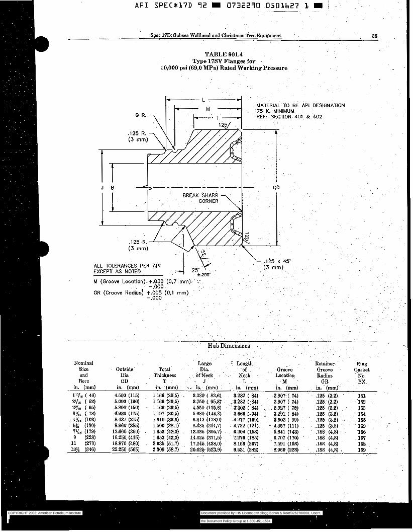
A P I SPECx17D 9 2 m 0732290 O503627 I m ~ ~~ ~~ . _ _ . ~ ~~ ~ ~~
Spec 17D Subsea Wellhead and Christmas Tree Equipment 36
TABLE 901.4 Type 17SV Flanges for
10,000 psi (69,O MPa) Rated Working Pressure
COPYRIGHT 2003; American Petroleum Institute
Document provided by IHS Licensee=Kellogg Borwn & Root/3262700001, User=, 09/10/2003 07:10:01 MDT Questions or comments about this message: please callthe Document Policy Group at 1-800-451-1584.
--`,,,``,```,`,`,``,`,,``,`,,`-`-`,,`,,`,`,,`---

__
A P I SPEC*37D 9 2 m 0332290 0503628 3 E
36 American Petroleum Institute
TABLE 901.4 (continued) Type 17SV Flanges for
10,000 psi (69,O MPa) Rated Working Pressure
O.D.
' f.250'
MATERIAL TO BE API DESIGNATION 75 K. MINIMUM REF. SECTION 401 & 402
TOLERANCE: R (Outside Dia.)
Size 2 1/16 Thru 5 1/8 f.062 Size 7 1/16 Thru 11 f .125
RL (Length of Ring) +.125 -.o00
RT (Depth of Large Dia.) +.O62 -.o00
RJ1 (Large I.D. Ring) +.O31 -.o00
RJ2 (Small I.D. Ring) +. 031 - . O00
C (Chamfer) +.o10 -.o00
Bolt Dio. Size 2 1/16 Thru 7 1/16 +.O60
-.o20
Size 9 Thru 11 +.o90 -.o20
(0.3 mm)
Basic Dimensions of Ring Bolts
Nominal Outside Depth Large Small Length Dia of Size and Dia. of of LG I.D. of ID of of Bolt Number Diaof Bore of Ring ID Ring Ring Ring Chamfer Circle of Bolt
Hub R OD RT W1 W 2 RL C BC Bolts Holes in. (mm) in. (mm), in. (mm) in. (mm) in. (mm) in. (mm) in. (mm) in. (mm) in. (mm)
ll:)'lfi ( 46) 7.38 (188) .964 (24,5) 4.662 (115,9) 3.312 ( 84,l) 2.450 ( 63) .125 (,3) 5.75 (146,l) 8 .88 (2-3) 2 % ~ ( 62) 7.88 (200) ,964 (24,s) 5.062 (128,6) 3.812 ( 96.8) , 2.450 ( 63) .125 (,3) 6.25 (158,8) 8 .88 (23) 29/16 ( 66) 9.12 (232) .964 (24,6) 5,862 (148,9) 4.612 (117,l) 2.470 ( 63) ,125 (,3) 7.25 (184,l) 8 1.00 (26) 3Ih6 ( 18) 10.62 (270) ,995 (25,3) -6.992 (177,6) 6.742 (1458) 2.834 ( 72) .125 (,3) 8.50 (2169) 8 1.12 (B)
6% (130) 14.05 (357) 1.299 (33,O) 10.022 (254,6) 8.397 (213,3) 3.900 ( 99) .126 (,3) 11.81 (300,O) 12 1.26 (32) 4'hC (103) 12.44 (316) 1.106 (28,l) 8.500 (215,9) 6.875 (174,6) 3.445 ( 88) ,125 (,3) 10.19 (258,8) 8 1.25 (32)
7 % ~ (179) 18.88 (480) 1.451 (369) 13.722 (348,5) 12.097 (307,3) 5.122 (130) .I88 (,5) 15.88, (403'4) 12 1.62 (42) 9 (228) 21.75 (562) 1.451 (36,9) 16.312 (409.7) 14.687 (373,O) 6.188 (158) .188 (,5) 18.75 '(496,3) 16 1.62 (42) 11 (n9) 26.75 (654) 1.833 (466) 18.932 (480,9) 17.307 (439,6) 7.072 (180) .I88 (,5) 22.25 .(666,2) 16 1.88 (48) 13% (346) 30.25 (768) 2.107 (53,5) 22.312 (566,7) 20.587 (525,4) 8.460 (215) 1.88 (,5) 26.50 :(673,1) 20 2.00 (51)
COPYRIGHT 2003; American Petroleum Institute
Document provided by IHS Licensee=Kellogg Borwn & Root/3262700001, User=, 09/10/2003 07:10:01 MDT Questions or comments about this message: please callthe Document Policy Group at 1-800-451-1584.
--`,,,``,```,`,`,``,`,,``,`,,`-`-`,,`,,`,`,,`---

.~ - .
Spec 17D: Subsea Wellhead and Christmas Bee Eqepment ..
~. 37 - .
.. ~. . .
TABLE 901.5. . .
. .
. . .~
ROUGH MACHINING DETAIL FOR ~.
CÖRilOSION RESISTANT API RING GROOVE .~
. . .~ .
Outside Outside Diameter Width Depth Diameter Width - Depth
Ring of Groove of Groove of Groove . ~. Ring - of Groove. ofGroove ~ of Groove Number A - B c ~ ~. Number -c A - B. ~- c -
in. (mm) ~ in, -.(mm) in. (mm) BX-152 3.72 ' ( 95,O) .77 (19,5) ~ .38 ~(10,Ö) I '" ~ Ri201 ~- -2.36 (- 59,94) .50 ( 12,7j . -.30 ( 7,62)
.~ ~.
"
in. (mm) in. (mm) -~ in. (mm). ~~
BX-153 4.38 (111,5) .83 (21,5) -41 (10,5) R-205 . 2.80 71,lg) .50 ( 12,7) ~ .42 (10,67) BX-154 6.01 (127,5) .88 (22,5)- ;44 (11,5) R-210 4;20 (106;68) .66 (16,76) . .39 (. 9,91) BX-156 6.26 (159,5) ~ -9'7 (25,O) .47 (12,O) R-215 -5.92 (150,39) .73 (€9,05) '.46 (11,43) BX-156 9.85 (250,5) 1.20 (31,O) .58 . ~(15,O) ~ ~
BX-157 12.10 (307,5) 1.32 (34,O) - .64 (16,5) BX-158 14.39 (366,O) 1.42 (36,5) .70 (18,O) BX-169 7.285'(185,0)- 0.842 (21,39) .52 (13,2) ~- . .
~~
.. ~~
~ "
.. .
NOTE: A l l w Wor greater for final machining of weld meday.
COPYRIGHT 2003; American Petroleum Institute
Document provided by IHS Licensee=Kellogg Borwn & Root/3262700001, User=, 09/10/2003 07:10:01 MDT Questions or comments about this message: please callthe Document Policy Group at 1-800-451-1584.
--`,,,``,```,`,`,``,`,,``,`,,`-`-`,,`,,`,`,,`---
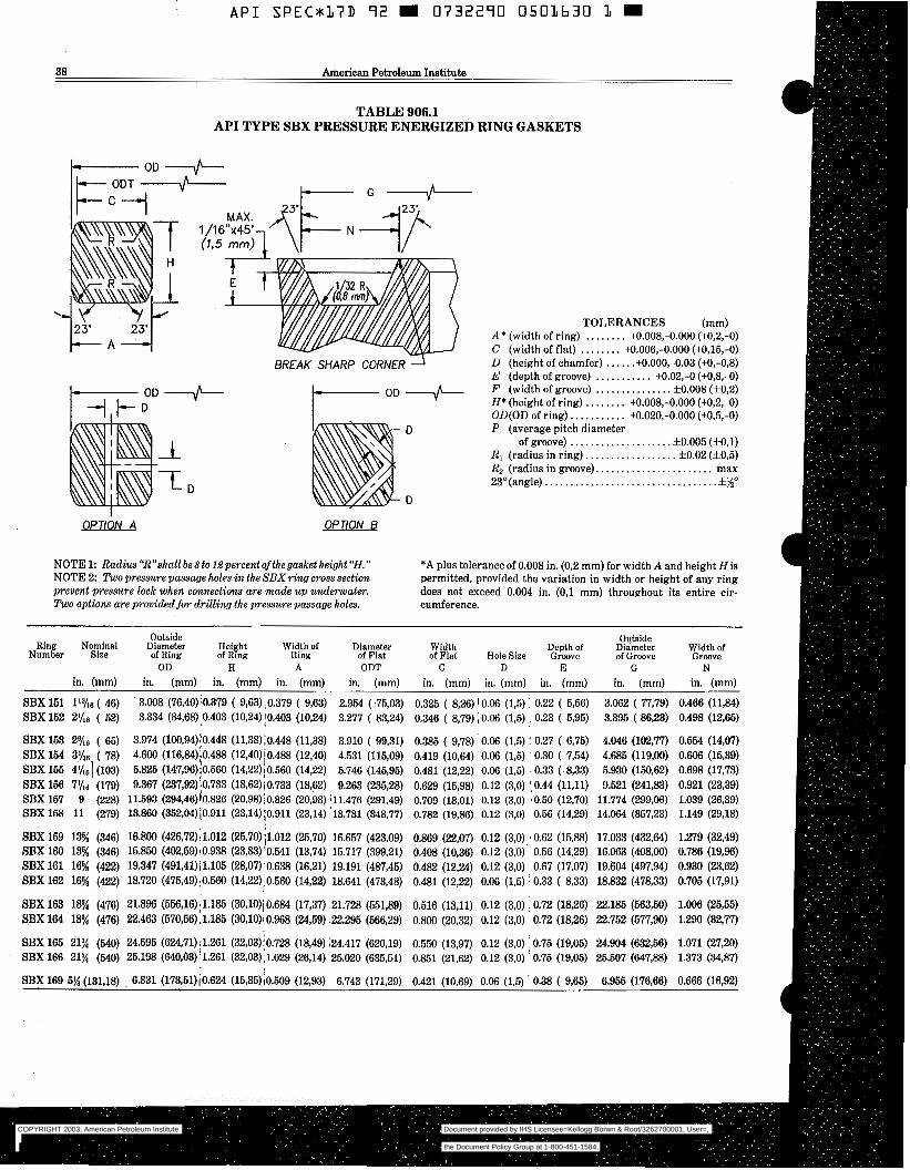
API SPECx17D 7 2 E 0732270 O501630 1 E
38 American Petroleum Institute
TABLE 906.1 API TYPE SBX PRESSURE ENERGIZED RING GASKETS
It-cl V
BREAK SHARP CORNER
OPTlON A OPTlON B
TOLERANCES (mm) A* (width of ring) . . . . . . . . M.008,-0.000 (+0,2,-0) C (width of flat) . . . . . . . . M.006,-0.000 (+0,15,-O) D (height of chamfer) . . . . . .+O.OOO,-0.03 (M,-0,8) E (depth of groove) . . , . . . . . . . . M.02,-O (+0,8,-0) F (width of groove) . . . . . . . . . . . . . . . f0.008 (f0,2) H* (height of ring) . . . . . . . . tO.008,-0.000 (+0,2,-0) OD(0D of ring). . . . . . . . . . . 4.020,-0.000 (+0,5,-0) P (average pitch diameter
of groove) . . . . . . . . . . . . . . . . . . . . f0.005 (f0,l) R, (radius in ring). . . . . . . . . . . . . . . . . . f0.02 (f0,5) R2 (radius in groove). . . . . . . . . . . . . . . . . . . . . . . max 23"(angle). . . . . . . . . . . . . . . . . . . . . . . . . . . . . . . . . .*%O
NOTE1: Radius"R"sh.allbe8tol&perce-ntofthegusketheigh~"H." *A plus tolerance of 0.008 in. (0,2 mm) for width A and height His NOTE 2: Two pressure passage holes in thg SBXring cross section permitted, provided the variation in width or height of any ring prevent pressure lock when connections are made up underwater. does not exceed 0.004 in. (0,l mm) throughout i t s entire cir- Two options are provided for drilling the pressure passage holes. cumference.
Outside Ring Nominal Diameter Height Widthof Diameter
Outside Number Size of Ring
Width Depth of Diameter Width of of Ring Ring H
of Flat A
of Flat Hole Size Groove ODT C D E G
of Groove Groove N OD
in. (mm) in. (mm) in. (mm) in. (mm) in. (mm) in. (mm) in. (mm) in. (mm) in. (mm) in. (mm)
SBX 151 113/6 ( 46) 3.008 (76,40)'0.379 ( 9,63) ,0.379 ( 9,63) 2.954 ( .75,03) 0.325 ( 8,26) 10.06 (1,5) : 0.22 ( 5 , s ) 3.062 ( 77,79) 0.466 (Il&) SBX 152 21/16 ( 52) 3.334 (84,68):0.403 (10,24)!0.403 (10,24) 3.277 ( 83,24) 0.346 ( 8,79) i 0.06 (1,5) , 0.23 ( 5,95) 3.395 ( 8623) 0.498 (12,65)
~ ~~
SBX 163 2% ( 65) 3.974 (100,94):0.448 (11,38)10.448 (11,38) 3.910 ( 99,31) 0.385 ( 9,78) 0.06 (1,5) I 0.27 ( 6,75) 4.046 (102,77) 0.554 (14,07)
SBX 165 4y161 (103) 5.825 (147,96)i0.560 (14,22);0.560 (14,22) 5.746 (145,95) 0.481 (1232) 0.06 (1,5) - 0.33 ( 8,33) 5.930 (150.62) 0.698 (17,73) SBX 156 7 % ~ (179) 9.367 (237,92):0.733 (18,62)¡0.733 (18,62) 9.263 (23528) 0.629 (15,98) 0.12 (3,O) 10.44 (11,ll) 9.521 (241,83) 0.921 (23,39) SBX 157 9 (228) 11.593 (294,46)[0.826 (20,98);0.826 (20,98) j11.476 (291.49) 0.709 (18,Ol) 0.12 (3,O) aO.50 (12,70) 11.774 (299,06) 1.039 (26.39) SBX 168 11 (279) 13.860 (352,04)10.911 (23,14)/0.911 (23,14) '13.731 (348.77) 0.782 (N,€%) 0.12 (3,O) 0.56 (1429) 14.064 (35733) 1.149 (29.18)
SBX 169 13% (346) 16.800 (426,72);1.012 (25,70)j1.012 (25,70) 16.657 (423,09) 0.869 (22.07) 0.12 (3,O) r0.62 (15.88) 17.033 (432,64) 1.279 (32.49) SBX 160 13% (346) 15.850 (402,59)~0.938 (23,831'0.541 (13,74) 15.717 (399,21) 0.408 (10.36) 0.12 (3,O) 0.56 (14,29) 16.063 (408,00) 0.786 (19,961 SBX 161 16% (422) 19.347 (491,41)j1.105 (28,07)'0.638 (16,21) 19.191 (487,45) 0.482 (12,24) 0.12 (3,O) 0.67 (17,07) 19.604 (49794) 0.930 (23,621 SBX 162 16% (422) 18.720 (475,49):0.560 (14,22):0.560 (14,22) 18.641 (473,48) 0.481 (12,n) 0.06 (1,5) I 0.33 ( 8,33) 18.832 (478,331 0.705 (17,91)
SBX 163 18% (476) 21.896 (566,16)11.185 (30,1O)i0.684 (17,37) 21.728 (551,89) 0.516 (13,ll) 0.12 (3,O) I0.72 (18,261 22.185 (563,501 1.006 (25,551 SBX 164 18% (476) 22.463 (570,66).1.185 (30,10)10.968 (24,59) 22.295 (566,29) 0.800 (20,32) 0.12 (3,O) 0.72 (18,26) 22.752 (577,90) 1.290 (32,771
SBX 165 21% (540) 24.595 (624,71);1.261 (32,03)!0.728 (18,49) i24.417 (620,19) 0.550 (13,97) 0.12 (3,O) 0.75 (19.05) 24.904 (632,56) 1.071 (27,20) SBX 166 21% (540) 25.198 (640,03):1.261 (32,03),1.029 (26,14) 25.020 (635,51) 0.851 (21,62) 0.12 (3,O) '0.75 (19,05) 25.507 (64738) 1.373 (3487)
SBX 169 5% (131,18) , 6.831 (173,51)¡0.624 (15,85)10.509 (12,93) 6.743 (171,29) 0.421 (10,69) 0.06 (1,Q ' 0.38 ( 9,65) 6.955 (17666) 0.666 (1632)
SBX 154 3'/16 ( 78) 4.600 (116,84)i0.488 (12,40)/0.488 (12,40) 4.531 (115,09) 0.419 ( 1 0 , ~ ) 0.06 (1,5) ' 0.30 ( 7,54) 4.685 (119,OO) 0.606 (15,391
COPYRIGHT 2003; American Petroleum Institute
Document provided by IHS Licensee=Kellogg Borwn & Root/3262700001, User=, 09/10/2003 07:10:01 MDT Questions or comments about this message: please callthe Document Policy Group at 1-800-451-1584.
--`,,,``,```,`,`,``,`,,``,`,,`-`-`,,`,,`,`,,`---
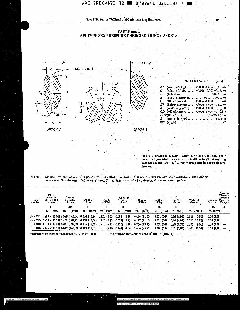
A P I SPEC*37D 92 0732290 0503633 3 :- ~~
~ ~ ~~
Spec 17D: Subsea Wellhead and Christmas Tree Equipment 39
TABLE 906.2 API TYPE SRX PRESSURE ENERGIZED RING GASKETS
I - A 4
OP77ON A
TOLERANCES (mm)
A* (width of ring)-. ..... tO.008,-0.000 (M,ZO,-O) ~C (width of flat). ....... tO.006,-0.000(+0,15,-0) - D (hole size) ..................... f0.02 (f0,5) E (depth of groove). ......... M.02.-O (+0,5,-O) G (OD of groove) ...... M.004,-0.000 (+0,10,-0) H* (heightof ring) ..... M.008,-0.000 (M,20,-0) N (width of groove). . , . +0.004,-0.000 (+OJO,-O) OD (OD of ring) ........... M.000,-0.006 (+0,-0,15) ODT(0D of flat) .................. +0.002(+0,05)
23O (angle) ............................... R (radius in ring) ..................... see note " . .
*A plus tolerance of in. 0.008 (0,2 mm) for width A and heighf H is permitted, provided the variation in width or height of any ring does not exceed 0.004 in. (0,l mm) throughout its entire circum- ference.
NOTE 1: The two pressure passage holes i l lwtra ted in the SRX ring cross section prevent pressure lock w h e n w n w t i o n s a r e ntade u n d m a t e r . Hole diameter shall be .06"(7 mm). Two options are prwided for d d l i n g the pressure passage hole.
Pitch n:̂ ",..* n..":-l-
Ring ~":-LL -e
Height Radius in Number of Rmg Ring
Width of Groove
of Ring and Groove
YI'SIIISLF.
Diameter of Ring
"UWlYIj
Width of Ring of Flat
Width me18111 "I
Outside Bevel
Depth of Groove
I P OD A C D H RI E F
SRX 201 SRX 205 SRX 210 SRX 215
in. (mm) in. (mm)
1.813 ( 46,04) 2.026 ( 46,04) 2.250 ( 57,15) 2.453 ( 62,31) 3.500 ( 8830) 3.844 ( 97,63) 5.125 (130.18) 5.647 (140,89)
in. (mm)
0.226 ( 6,74) 0.219 ( 5,M) 0.375 ( 9,53) 0.469 (11,91)
in. (mm)
0.126 (3,20) 0.120 (3,05) 0.213 (5,41) 0.210 (5,33)
in. (mm) in. (mm)
0.057 (1,45) 0.445 (11,30) . 0.072t (1,83) 0.437 (11,lO) 0.125t (3,18) 0.750 (19,05) 0.167t (4,24) 1.ooO (25,40)
in. (mm)
0.02$ (0,5) 0.02$ (0,5) 0.03$ (0,8) 0.06% (15)
in. (mm)
0.16 (4,06) 0.16 (4,06) 0.25 (6,35) 0.31 (7,87)
in. (mm)-
0.219 ( 556) 0.219 ( 556) 0.375 ( 9,53) 0.469 (11,91)
I volerance on these dimensions is +O -.O15 (+O -0,4) $Tolerance on these dimensions is t0.02 -O (M,5 -0)
Distance Approx.
~ .........
Radius in Made Up Between.
Groove . Flanges
.~ R2 S in. (mm)
0.03 (0,8) - 0.02 (0,5) - 0.03 (O,@ - 0.03 (0,s) -
f
COPYRIGHT 2003; American Petroleum Institute
Document provided by IHS Licensee=Kellogg Borwn & Root/3262700001, User=, 09/10/2003 07:10:01 MDT Questions or comments about this message: please callthe Document Policy Group at 1-800-451-1584.
--`,,,``,```,`,`,``,`,,``,`,,`-`-`,,`,,`,`,,`---

40 American Petroleum Institute
conform to Table 901.5, or other weld prepa- rations may be employed where the strength of the overlay alloy equals or exceeds the strength of the base materials. Dimensions for Type 17SS flange ring grooves shall conform to Table 906.1. Integral Flange Exceptions. Type 17SS flanges used as end connections on subsea completion equipment may have entrance bevels, counterbores or recesses t o receive running/test tools, plugs, etc. The dimen- sions of such entrance bevels, counterbores, and recesses are not covered by this specifica- tion and may exceed the B dimension of the Tables. The manufacturer shall ensure that the modified flange designs shall meet the requirements of Section 303.3 of this specifi- cation. Threaded Flanges. Threaded flanges shall not be used on subsea completions equíp- ment, except as provided in Section 903. Dimensions of threaded flanges, if used, shall comply with API Specification 6A, Sec- tion 901. Weld Neck Flanges, Bore and Wall Thick- ness: The bore diameter J shall not exceed the values shown in Table 901.2. The speci- fied bore shall not result in a weld-end wall thickness less than 87.5 percent of the nomi- nal wall thickness of the pipe to which the flange is to be attached Weld End Preparation: Dimensions for weld end preparation shall conform to Figure 901.2. Taper; When the thickness at the welding end is at least 3/32" (2,5 mm) greater than that of the pipe, and the additional thickness decreases the inside diameter, the flange shall be taper bored from the weld end at a slope not exceeding 3 to 1. NOTE: Due to smaller maximum bore di- mensions, Type 17SS weld neck flanges are not intended to be welded to wellhead and completion equipment in this specification. Theirpurpose is to provide a welding transi- tion between a flange and a pipe.
901.213(3) Ring Grooves. Corrosion resistant in- layed ring grooves for 2" (52 mm) through 11" (279 mm) API Type 17SS flanges shall comply with the requirements of Table 901.5 and Section 404.3.
Corrosion resistant inlays for 13 5/8" (346 mm) through 21 1/4' (540 mm), 5000 psi, Type 6BX flanges shall comply with the requirements of API Specification 6A, Section 901. 901.2~ Standard Subsea Flanges - Working
Pressures 10,000 or 16,000 Psi (69,O or 103,6 MPa) (Type 6BX). Standard flanges for use in 10,000 or 15,000 psi (69,O or 103,5 MPa) working pressure subsea completions equipment shall comply with the requirements for API Type 6BX flanges, as defined in
API Specification 6A. These flanges are ring joint type flanges, designed for face-to-face make-up. The connection make-up bolting force reacts primarily on the flange face.
Corrosion resistant inlayed ring grooves for API Type 6BX flanges shall comply with the require- ments of API 6A, Section 901.
901.2d Segmented Flanges - Working Pres- sure 5000 Psi. Segmented flanges should not be used except where closely spaced multiple connec- tions do not permit the use of full size standard flanges. If segmented flanges are used, there shall be at least two pressure controlling valves between the segmented flange and the wellhead. Segmented flanges for use on subsea completion equipment shall comply with the requirements of API Specification 6A, Section 901. These flanges are ring joint type flanges, designed for face-to-face make-up. The connection make-up bolting force reacts primarily on the flange face.
Note that API segmented flanges are not recom- mended for hydrogen sulfide service.
Segmented flanges shall not be used for applica- tions involving external - bending moments unless auxiliary support is provided to isolate the flange from the external loads.
The large angular rotations often required to align mating segmented flanges may induce excessive tor- sional loads which could damage flexible piping (ref. API Recommended Practice 17B). If segmented flanges are used with flexible piping, the loads acting on these flanges and flexible piping shall not exceed the limits established by their respective manufacturers.
Note that API segmented flanges use type Rx or S M gaskets. Since RX ring gaskets are not vented and could trap fluid during make up, Type SRX gaskets shall be used with segmented flanges which, per the manufacturer's written specifications, will be made up subsea.
Corrosion-resistant inlayed ring grooves are not allowed for segmented flanges (reference API Speci- fication 6A, Section 901.2d(5)). Therefore, segmented flanges must be manufactured from corrosion-resis- tant materials.
901.28 Swivel Flanges - Working Pressures 5000 or 10,000 Psi (34,s or 69,O MPa) (Type 17SV)
901.2dl) General. Type 17SV flanges are mul- tiple-piece assemblies in which the flange rim is free to rotate relative to the flange hub. Type 17SV flanges may be used on subsea completions equip- ment where it is difficult or impossible to rotate either of the flange hubs to align the mating bolt holes. Type 17SV flanges mate with standard Type 6BX and 17SS flanges of the same size and pressure rating.
Type 17SV swivel flanges are of the ring joint type and are designed for face-to-face make-up. The connection make-up bolting force reacts primarily on the flange face.
COPYRIGHT 2003; American Petroleum Institute
Document provided by IHS Licensee=Kellogg Borwn & Root/3262700001, User=, 09/10/2003 07:10:01 MDT Questions or comments about this message: please callthe Document Policy Group at 1-800-451-1584.
--`,,,``,```,`,`,``,`,,``,`,,`-`-`,,`,,`,`,,`---
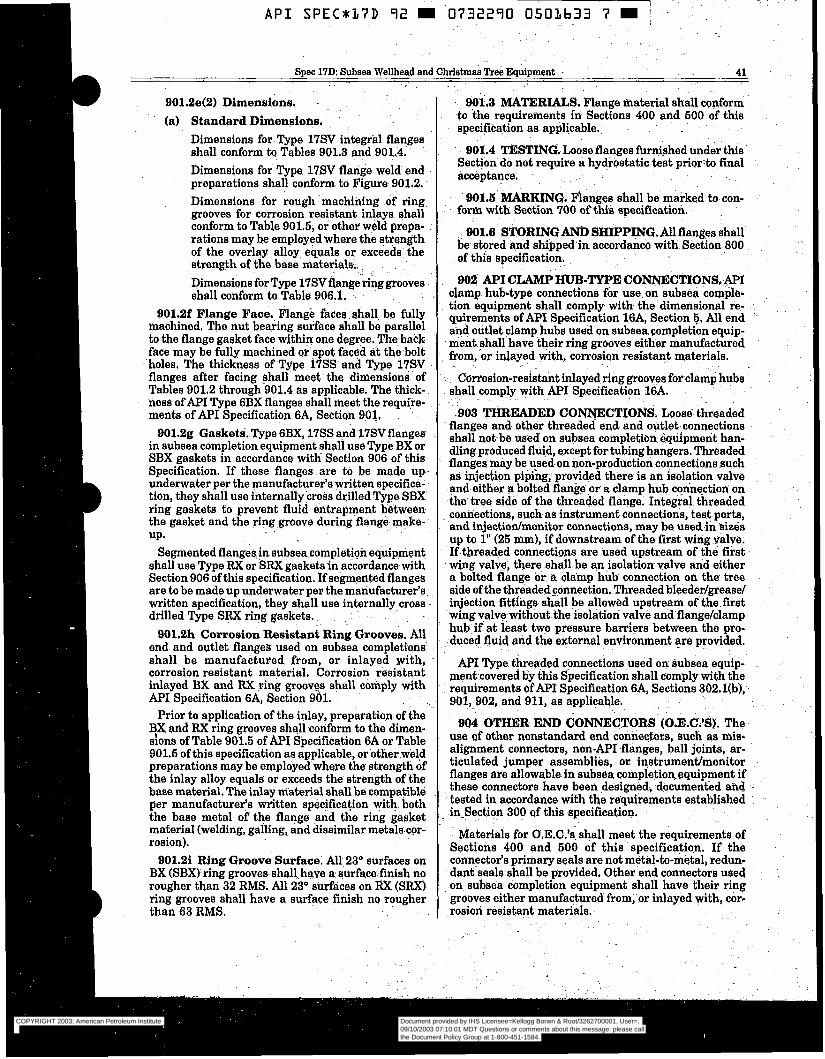
A P I S P E C x 3 7 D 92 m 0732270 O503633 7 E i ~~ ~ .~ ~ -~ ~~~~ ~ ~~ ~ ~.
Spec 17D: Subsea Wellhead and Christmas Tree Equipment :. 41
901.2e(2) Dimensions. ~
(a) Standard Dimensions. Dimensions for Type 17SV integral flanges shall conform to Tables 901.3 and ~901.4. Dimensions for Type 17SV flange weld end preparations shall conform to Figure 901-2. - Dimensions for rough machining of ring. grooves for corrosion resistant inlays shall conform to Table 901.5, or other weld prepa- rations may be employed where the strength of the overlay alloy equals or exceeds ~ the strength of the base materials, . .
Dimensions for Type 17SV flange-ring grooves shall conform to Table 906.1..
901.2f Flange Face. Flange faces shall be fully machined. The nut bearing surface shall be parallel to the flange gasket face within one degree. The back face may be fully machined. or spot faced át the boIt
h hol es. The thickness of Type 17SS and Type 17SV flanges after facing-shall meet the dimensions of Tables 901.2 through 901.4 äa-applicable. The thick- ness of A P I Type 6BX flanges shall meet the require- ments of API Specification 6A, Section 901. .
901.2g GasketË. Type 6BX, 17SS and 17SVflanges in subsea completion equipment shall use Type BX or SBX gaskets in accordance witk Section 906 of this Specification. If these. flanges are to be made up underwater per the manufacturer's written specifica- tion, they shall use internally cross. drilled Type SBX~ ring gaskets to prevent fluid entrapment between the gasket and the ring.groove during flange make- UP.
Segmented flanges in subsea completion equipment shall use Type RX or SRX gaskets in accordance with Section 906 of this specification, If segmented flanges are to be made up underwater per the manufacturer's: written specification, they shall use internally cross drilled Type SRX ring gaskets.
901.2h Corrosion Resistant Ring Grooves.-All end and outlet flanges- used on subsea completions shall be manufactured from, or inlayed with, corrosion resistant material, Corroaioti resistant inlayed BX and RX ring groovgs shall comply with API specification 6A, Section 901.
Prior to application of the inlay, preparation of the BX and RX ring grooves shall conform to the dimen- sions of Table 901.5 of API Specification 6A or Table 901.5 of this specification as applicable, or other weld preparations may be employed where the strength of the inlay alloy equals or exceeds the strength of the base material. The inlay máterial shall be compatible per manufacturer's written specification with both the base metal of the flange and the ring gasket maeerial (welding, galling, and dissimilar metals cor- rosion).
901.2i Ring Groove Surface. All 23" surfaces on BX (SBX) ring grooves shall have a surfacehiah no rougher than 32 RMS. All 23" surfaces on IiX (SRX) ring grooves shall have a surface finish no rougher than 63 RMS.
. . .
. -
COPYRIGHT 2003; American Petroleum Institute
Document provided by IHS Licensee=Kellogg Borwn & Root/3262700001, User=, 09/10/2003 07:10:01 MDT Questions or comments about this message: please callthe Document Policy Group at 1-800-451-1584.
--`,,,``,```,`,`,``,`,,``,`,,`-`-`,,`,,`,`,,`---
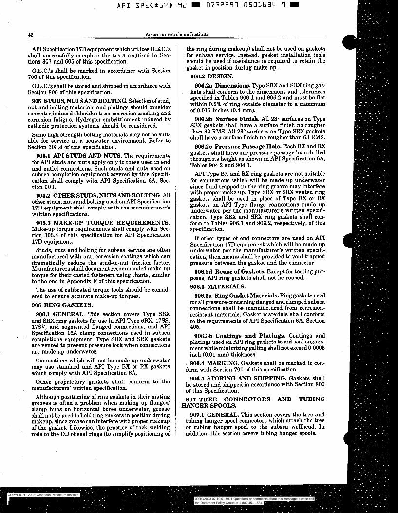
API SPEC*:L7D 92 S 0 7 3 2 2 9 0 0501634 9 m
42 American Petroleum Institute
API Specification 17D equipment which utilizes 0.E.C.k shall successfully complete the tests required in Sec- tions 307 and 606 of this specification.
O.E.C.’s shall be marked in accordance with Section 700 of this specification.
O.E.C.’s shall be stored and,shipped in accordance with Section 800 of this specification.
906 STUDS, NUTS AND BOLTING. Selection of stud, nut and bolting materials and platings should consider seawater induced chloride stress corrosion cracking and corrosion fatigue. Hydrogen embrittlement induced by cathodic protection systems should be considered.
Some high strength bolting materials may not be suit- able for service in a seawater environment. Refer to Section 303.4 of this specification.
906.1 API STUDS AND NUTS. The requirements fór API studs and nuts apply only to those used in end and outlet connections. Such studs and nuts used on subsea completion equipment covered by this Specifi- cation shall comply with API Specification 6A, Sec- tion 903.
906.2 OTHER STUDS, NUTS AND BOLTING. All other studs, nuts and bolting used on A P I Specification 17D equipment shall comply with the manufacturer‘s written specifications.
Make-up torque requirements shall comply with Sec- tion 303,4 of this specification for API Specification 17D eqvipment.
Studs, nuts and bolting for subsea service are often manufactured with anti-corrosion coatings which can dramatically reduce the stud-to-nut friction factor. Manufacturers shall document recommended make-up torque for their coated fasteners using charts, similar to the one in Appendix F of this specification.
The use of calibrated torque tools should be consid- ered to ensure accurate make-up torques. 906 RING GASKETS,
906.3 MAKE-UP TORQUE REQUIREMENTS.
906.1 GENERAL. This section covers Type SBX and SRX ring gaskets for use in API Type 6BX, 17SS, 17SV, and segmented flanged connections, and API Specification 16A clamp connections used in subsea completions equipment. Type SBX and SRX gaskets are vented to prevent pressure lock when connections are made up underwater.
Connections which will not be made up underwater may use standard and M I Type BX or RX gaskets which comply with API Specification 6A.
Other proprietary gaskets shall conform to the manufacturers’ written specification.
Although positioning of ring gaskets in their mating grooves is often a problem when making up flanged clamp hubs on horizontal bores underwater, grease shall not be used to hold ring gaskets in position during makeup, since grease can interfere with proper makeup of the gasket. Likewise, the practice of tack welding rods to the OD of seal rings (to simplify positioning of
the ring during makeup) shall not be used on gaskets for subsea service. Instead, gasket installation tools should be used if assistance is required to retain the gasket in position during make up.
906.2 DESIGN. 906.2a Dimensions. Type SBX and SRX ring gas-
kets shall conform to the dimensions and tolerances specified in Tables 906.1 and 906.2 and must be flat within 0.2% of ring outside diameter to a maximum of 0.015 inches (0.4 mm).
906.2b Surface Finish. AU 23” surfaces on Type SBX gaskets shall have a surface finish no rougher than 32 RMS. All 23’ surfaces on Type SRX gaskets shall have a surface finish no rougher than 63 RMS.
906.2~ Pressure Passage Hole. Each BX and RX gaskets shall have one pressure passage hole drilled through its height as shown in API Specification 6A, Tables 904.2 and 904.3.
API Type BX and RX ring gaskets are not suitable for connections which will be made up underwater since fluid trapped in the ring groove may interfere with proper make up. Type SBX or SRX vented ring gaskets shall be used in place of Type BX or RX gaskets on A P I Type flange connections made up underwater per the manufacturer’s written specifi- cation. Type SBX and SRX ring gaskets shall con- form to Tables 906.1 and 906.2, respectively, of this specification.
If other types of end connectors are used on API Specification 17D equipment which will be made up underwater per the manufacturer’s written specifi- cation, then means shall be provided to vent trapped pressure between the gasket and the connector.
906.2d Reuse of Gaskets. Except for testing pur- poses, A P I ring gaskets shall not be reused. 906.3 MATERIALS.
906.3a Ring Gasket Materials. Ring gaskets used for all pressure-containing flanged and clamped subsea connections shall be manufactured from corrosion- resistant materials. Gasket materials shall conform to the requirements of API Specification 6A, Section 405.
906.3b Coatings and Platings. Coatings and platings used on API ring gaskets to aid seal engage- ment while minimizing galling shall not exceed 0.0005 inch (0.01 mm) thickness. 906.4 MARKING. Gaskets shall be marked to con-
form with Section 700 of this specification. 906.6 STORING AND SHIPPING. Gaskets shall
be stored and shipped in accordance with Section 800 of this Specification. 907 TREE CONNECTORS AND TUBING
907.1 GENERAL. This section covers the tree and tubing hanger spool connectors which attach the tree or tubing hanger spool to the subsea wellhead. In addition, this section covers tubing hanger spools.
HANGER SPOOLS.
COPYRIGHT 2003; American Petroleum Institute
Document provided by IHS Licensee=Kellogg Borwn & Root/3262700001, User=, 09/10/2003 07:10:01 MDT Questions or comments about this message: please callthe Document Policy Group at 1-800-451-1584.
--`,,,``,```,`,`,``,`,,``,`,,`-`-`,,`,,`,`,,`---
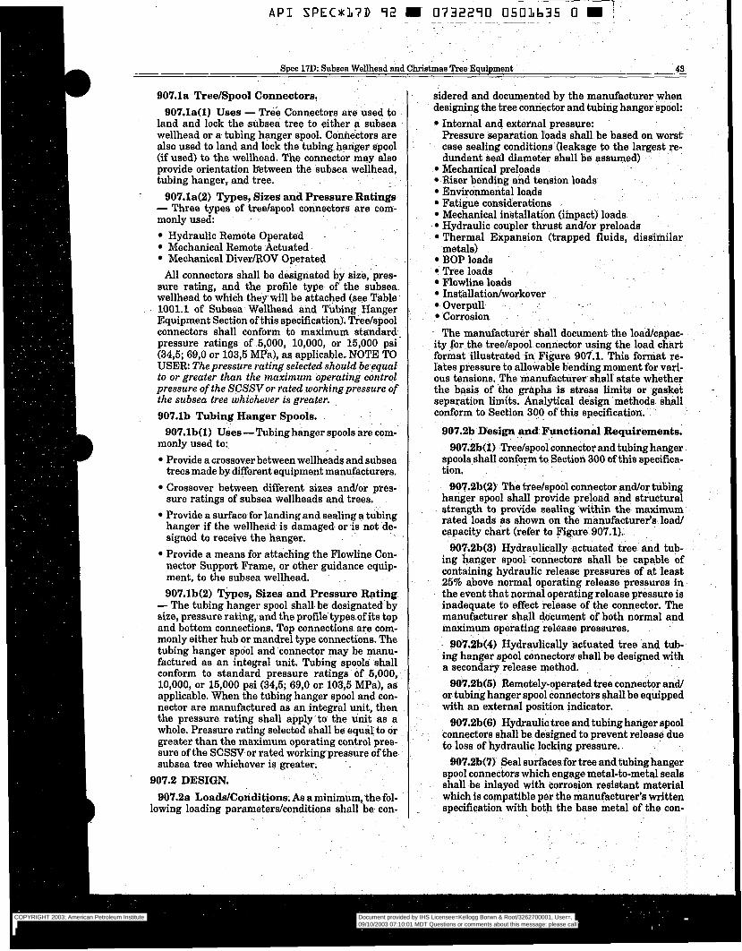
A P I SPEC*KL7D 92 W 0732290 0501b35 O W i ~~ ~~~ ~~ ~~ . -~
Spec 17D: Subsea Wellhead and Christmas Tree Equipment 43
907.la Tree/Spool Connectors, 907.la(l) Uses - Tree Connectors are used to
land and lock the -subsea tree to either a subsea wellhead or a tubing hanger spool. Connectors are also used to land and lock the tubing hanger spool (if used) to the wellhead; The connector may also provide- orientation between the subsea wellhead, tubing hanger, and tree,
. 907.1a(2) Types, Sizes and Pressure Ratings - Three types of tree/spool connectors are com- monly used:
Hydraulic Remote Operated Mechanical Remote Actuated Mechanical DiverROV Operated . .
All connectors shall be designated by aize, pres- sure rating, and the profile type of the subsea. wellhead to which they will be attached (see Table 1001.1 of Subsea Wellhead and ‘hbing Hanger Equipment Section ofthis specification). Tree/spool connectors shall conform to maximum standard pressure ratings of 5,000, 10,000, or 15,000 psi (34,5; 69,O or 103,5 MPa), as applicable. NOTE TO USER: The pressure rating selected should be ëqual to or greater than the maximum operating control pressure of the SCSSVor rated working pressure of the subsea tree Whichever is greater. 907.lb Tubing Hanger Spools.
907.lb(l) Uses - Tubing hanger spools are com- monly used to:
Provide a crossover between wellheads and subsea trees made by different equipment manufacturers. Crossover between different sizes and/or pres- sure ratings of subsea wellheads and trees, Provide a surface for landing and sealing a tubing hanger if the wellhead is damaged or is not de- signed to receive the hanger. Provide a means for attaching the Flowline Con- nector Support Frame, or other guidance equip- ment, to the subsea wellhead. 907.1b(2) Types, Sizes and Pressure Rating - The tubing hanger spool shall be designated by
size, pressure rating, and the profile types of its top and bottom connections, Top connections. are com- monly either hub or mandrel type connections. The tubing hanger spool and connector may be manu- factured as an integral unit. Tubing spools shall conform to standard pressure ratings of 5,000, 10,000, or 15,000 psi (343; 69,O or 103,5 MPa), as applicable. When the tubing hanger apool and con- nector are manufactured as an integral unit, th en the pressure rating shall apply to the unit as a whole. Pressure rating selected shall be equal to or greater than the maximum operating control pres- sure of the SCSSV or rated working pressure of the subsea tree whichever is greater;
907.2 DESIGN. 907.2a LoaddConditions. As a minimum, thefol-
lowing loading parameterskonditions shall be con-
sidered and documented by the manufacturer when designing the tree connector and tubing hanger spool:
Internal and external pressure: Pressure separation-loads shall. be based on worsf; case sealing conditions (leakage to the largest re- dundant seal diameter shall be assumed) Mechanical preloads Riser bending and tension loads Environmental loads Fatigue considerations Mechanical installation (impact) loads Hydraulic coupler thrust and/or preloads Thermal Expansion (trapped fluids, dissimila metals) BOP loads Tree loads Flowline loads Installatiodworkover
.~
Overpull Corrosion
- The manufacturer shall document the load/capac- ity forthe tree/spool connector using the load chart .format illustrated in Figure 907.1. This format re- lates pressure to allowable bending moment for vari- ous tensions. The manufacturer shall state whether the basis of the graphs is stress limita or gasket - separation limits. Analytical design methods áhall conform to Section 300 of this specification.
907.2b Design and Functional Requirements. 907,2b(1) -Tree/spool connector and tubing hanger
spools shall conform to Section 300 of this specifica- tion.
907.21362) The tree/spool connector and/or tubing hanger spool shall provide preload and strictural strength to provide sealing within the maximum -
rated loads as shown on the manufacturer’s load/ capacity chart (refer to Figure 907.1).
907.2b(3) Hydraulically actuated tree and tub- ing hanger spool -connectors shall be capable of containing hydraulic release pressures of at least 25% above normal operating release pressures in the event that normal operating release pressure is inadequate to effect release of the connector, The manufacturer shall document of both normal and maxim- operating release pressures,
907.2b(4) Hydraulically actuated tree and tub- ing hanger spool connectors shall be designed with a secondary release method.
907.2b(S) Remotely-operated tree connector and/ or tubing hanger spool connectors shall be equipped with an external position indicator.
907.2b(6) Hydraulic tree and tubing hanger spool . . connectors shall be designed to prevent release due
to loss of hydraulic locking pressure; 907.2b(7) Seal surfaces for tree and tubing hanger
spool connectors which engage metal-to-metal seals shall be inlayed with corrosion resistant material which is compatible per the manufacturer’s written specification with both the base metal of the con-
COPYRIGHT 2003; American Petroleum Institute
Document provided by IHS Licensee=Kellogg Borwn & Root/3262700001, User=, 09/10/2003 07:10:01 MDT Questions or comments about this message: please callthe Document Policy Group at 1-800-451-1584.
--`,,,``,```,`,`,``,`,,``,`,,`-`-`,,`,,`,`,,`---
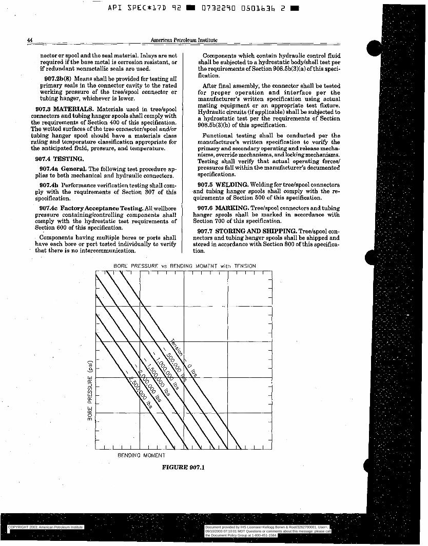
A P I SPEC*:17D 9 2 m 0732290 0501636 2 W
44 American Petroleum Inetitute
nector or spool and the seal material. Inlays are not required if the base metal is corrosion resistant, or if redundant nonmetallic seals are used.
907.2b(8) Means shall be provided for testing all primary seals in the connector cavity to the rated working pressure of the tree/spool connector or tubing hanger, whichever is lower.
907.3 MATERIALS. Materials used in tree/spool connectors and tubing hanger spools shall comply with the requirements of Section 400 of this specification. The wetted surfaces of the tree connector/spool and/or tubing hanger spool should have a materials class rating and temperature classification appropriate for the anticipated fluid, pressure, and temperature.
907.4 TESTING. 907.4a General. The following test procedure ap-
plies to both mechanical and hydraulic connectors. 907.4b Performance verification testing shall com-
ply with the requirements of Section 307 of this specification.
907.4~ Factory Acceptance Testing. All wellbore pressure containing/controlling components shall comply with the hydrostatic test requirements of Section 600 of this specification.
Components having multiple bores or ports shall have each bore or port tested individually to verify that there is no intercommunication.
Components which contain hydraulic control fluid shall be subjected to a hydrostatic body/shell test per the requirements of Section 908.6b(3)(a) of this speci- fication.
After final assembly, the connector shall be tested for proper operation and interface per the manufacturer's written specification using actual mating equipment or an appropriate test fixture. Hydraulic circuits (if applicable) shall be subjected to a hydrostatic test per the requirements of Section 908.5b(3)(b) of this specification.
Functional testing shall be conducted per the manufacturer's written specification to verify the primary and secondary operating and release mecha- nisms, override mechanisms, and lockingmechanisms. Testing shall verify that actual operating forced pressures fall within the manufacturer's documented specifications.
907.6 WELDING. Welding for tree/spool connectors and tubing hanger spools shall comply with the re- quirements of Section 500 of this specification.
907.6 MARKING. Tree/spool connectors and tubing hanger spools shall be marked in accordance with Section 700 of this specification.
907.7 STORING AND SHIPPING. Tree/spool con- nectors and tubing hanger spools shall be shipped and stored in accordance with Section 800 of this specifica- tion.
BORE PRESSURE vs BENDING MOMENT with TENSION
BENDING MOMENT
FIGURE 907.1
COPYRIGHT 2003; American Petroleum Institute
Document provided by IHS Licensee=Kellogg Borwn & Root/3262700001, User=, 09/10/2003 07:10:01 MDT Questions or comments about this message: please callthe Document Policy Group at 1-800-451-1584.
--`,,,``,```,`,`,``,`,,``,`,,`-`-`,,`,,`,`,,`---
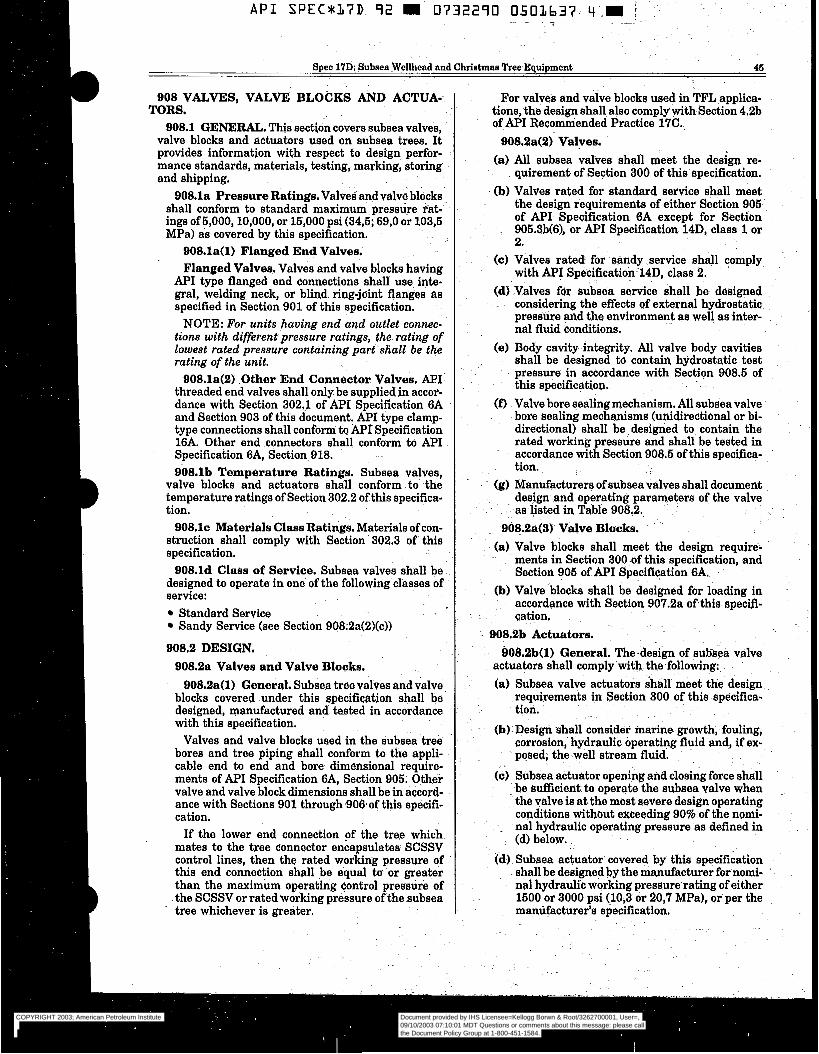
A P I SPEC*I,7D 72 m 0732270 0501,637 4 .m i . .
~- ~ -~ ~ ~-
Spec 17D: Subseawellhead and Christmas Tree Equipment 46
908 VALVES, VALVE BLOCKS AND ACTUA- TORS.
908.1 GENERAL. T h i s section covers subsea valves, valve blocks and actuators used on subsea trees, It provides information with respect to design perfor- mance standards, materials, testing, marking, storing and shipping.
908.la Pressure Ratings. Valves and valve blocks shall conform to standard maximum pressure rat- ings of5,000,10,000, or 15,000 psi (34,5; 69,O or 103,5 MPa) as covered by this specification.
908.la(l) Flanged End Valves. Flanged Valves. Valves and valve blocks having
API type flanged end connections shall use inte- gral, welding neck, or blind ring-jdnt flanges a s specified in Section 901 of this specification.
NOTE: For units having end and outlet connec- tions with differentpressure ratings, the- rating of lowest rated pressure containing part~shall be the rating of the unit.
908.1a(2) .Other End Connector Valves. N I threaded end valves shall only be supplied .in accor- dance with. Section 302,l of API Specification 6A and Section 903 of this document. API type clamp- type connections shall conform to A P T Specification 16A. Other end connectors shall conform to API Specification 6A, Section 918. 908.lb Temperature Ratings. Subsea valves,
valve blocks and actuators shall conform to the temperature ratings of Section 302.2 of this specifica- tion.
908.1~ Materials Class Ratings. Materials of con- struction shall comply with Section 302.3 of this specification.
908.ld Clase of Service. Subsea valves shall be designed to operate in one of the following classes of service:
Standard Service Sandy Service (see Section 908;2a(2)(c))
908.2 DESIGN. 908.2a Valves and Valve Blocks.
908.2a(1) General. Subsea tree valves and valve blocks covered under this spécification shall be designed, manufactured and tested in accordance with this specificafion.
Valves and valve blocks used in the subsea tree bores and tree piping shall conform to the appli- cable end to end and bore dimensional require- ments of API Specification 6A, Section 905. Other valve and valve block dimensions shall be in accord- ance with Sections 901 through 906.of this specifi- cation.
If the lower end connection pf the tree which mates to the tree connector encapsulates SCSSV control lines, then the rated working pressure of this end connection shall be equal t i o r greater than the maximum operating control pressure of the SCSSV or rated working pressure of the subsea tree whichever is greater.
For valves and valve blocks used in TF% applica- tions, the design shall also comply with Section 4.2b of @I Recomniended Practice 17C.
908.2a(2) Valves. (a) All subsea valves shall meet the design re-
quirement. of Section 300 of this specification. . (b) Valves rated for standard service shall meet
the design requirements of either Section 905 of API Specification 6A except for Section
~ 905.3b(6), or API Specification 14D, class 1 or 2.
(c) Valves rated- for sandy service shall comply with A P I Specification 14D, class 2.
(d) Valves for subsea service shall be designed . considering the effects of external hydrostatic
pressure and the environment as well as inter- nal fluid conditions.
(e) Body cavity integrity. All valve body cavities shall be designed to contain hydrostatic test pressure in accordance with Section. 908.5 of this specification. . - .
(f) Valve bore sealing mechanism. All subsea valve bore sealing mechanisms (unidirectional or bi- directional) shall be designed to contain the rated working pressure and shall be tested in accordance with Section 908.5 of this specifica- tion.
(g) Manufacturers of subsea valves shall document design and operating parameters of the valve
:~ as-listed inTable 908.2. ~ ~
908.2a(3) Valve Blocks. (a) Valve blocks shall meet the design require-
menta in Section 300 of this specification, and Section 905 of A P T Specification 6A.
(b) Valve blocks shall be designed for loading in accordance with Section 907.2a ofthis speci-fi- cation.
. .
908.2b Actuators. 908.213(1) General. The-design of subsea valve
actuators shall comply with the following:. (a) Subsea valve actuators- shall meet the design
requirements Section 300 of this specifica-
(b) Design shall consider marine growth, fouling, corrosion, hydraulic operating fluid and, if ex- posed, the well stream fluid. . ~
.(c) Subsea actuator opening and closing force shall be sufficient to operate the subsea valve when the valve is at the most Bevere design operating conditions without exceeding 90% of the nomi-
. nal hydraulic operating pressure as defined in
cd) Subsea actuator covered by this specification - shall be designed by the manufacturer for nomi- nal hydraulic working pressure-rating of either 1500 or 3000 psi (10,3 or 20,7 MPa), or per the manüfacturer’s specification.
~ tion.
. (d) below.
COPYRIGHT 2003; American Petroleum Institute
Document provided by IHS Licensee=Kellogg Borwn & Root/3262700001, User=, 09/10/2003 07:10:01 MDT Questions or comments about this message: please callthe Document Policy Group at 1-800-451-1584.
--`,,,``,```,`,`,``,`,,``,`,,`-`-`,,`,,`,`,,`---
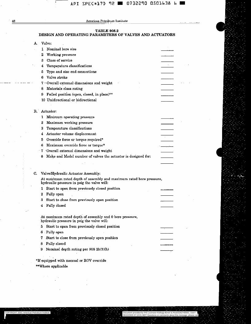
I A P I S P E C P 1 7 D 9 2 m 0732290 0501638 b m
46 American Petroleum Institute
TABLE 908.2 DESIGN AND OPERATING PARAMETERS OF VALVES AND ACTUATORS
A. Valve: 1 Nominal bore size 2 Working pressure 3 Class of service 4 Temperature classifications 5 Type and size end connections 6 Valve stroke 7 - Overall-external-dimensions and weight 8 Materials class rating 9 Failed position (open, closed, in place)** 10 Unidirectional or bidirectional
~" ~.~ -~
B. ' Actuator: 1 Minimum operating pressure 2 Maximum working pressure 3 Temperature classifications 4 Actuator volume displacement 5 Override force or torque required* 6 Maximum override force or torque* 7 -Overall external dimensions and weight 8 Make and Model number of valves the actuator is designed for:
C. ValveLHydraulic Actuator Assembly: At maximum rated depth of assembly and maximum rated bore pressure, hydraulic pressure in psig the valve will: 1 Start to open from previously closed position 2 Fully open 3 Start to close from previously open position 4 Fully closed
At maximum rated depth of assembly and O bore pressure, hydraulic pressure in psig the valve will: 6 Start to open from previously closed position 6 Fully open 7 Start to close from previously open position 8 Fully closed 9 Nominal depth rating per 908 2b(3)(h)
*If equipped with manual or ROV override **Where applicable
COPYRIGHT 2003; American Petroleum Institute
Document provided by IHS Licensee=Kellogg Borwn & Root/3262700001, User=, 09/10/2003 07:10:01 MDT Questions or comments about this message: please callthe Document Policy Group at 1-800-451-1584.
--`,,,``,```,`,`,``,`,,``,`,,`-`-`,,`,,`,`,,`---
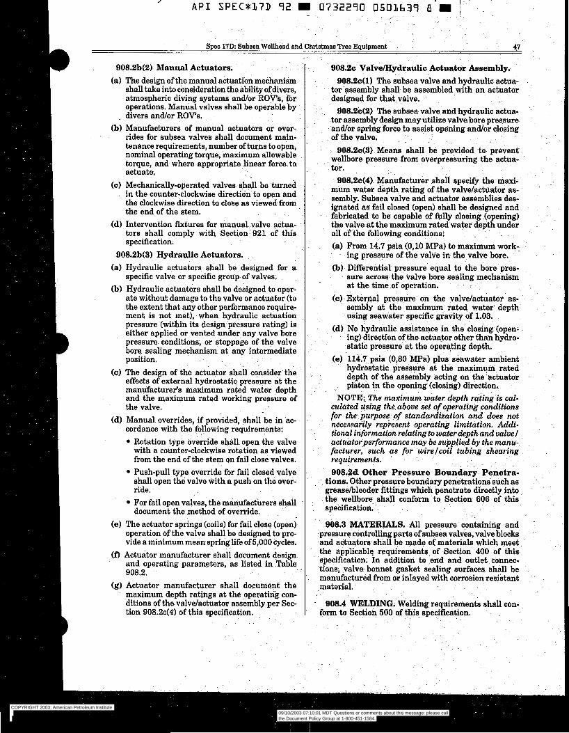
Spec 17D: Subsea Wellhead and Christmas P e e Equipment 41
908.213(2) Manual Actuators. (a) The design of the manual actuation mechanism
shall take into consideration the ability of divers, atmospheric diving systems and/or IlOVs, for operations. Manual valves shall be operable by
(b) Manufacturers of manual actuators or over- rides for subsea valves shall document main- tenance requirements] number of turns to open, nominal operating torque, maximum allowable
. torque, and where appropriate linear force to actuate.
(c) Mechanically-operated valves. shall be turned in the counter-clockwise direction-to open and the clockwise direction to close as viewed,from the end of the stem.
(d) Intervention fixtures for manual valve äctua- tors shall camply with Section 921 of this specification.
. divers and/or ROV's.
908.2b(3) Hydraulic Actuators. (a) Hydraulic actuators~ shall be designed for a
specific valve or specific group of valves. (b) Hydraulic actuators shall be designed to oper-
ate without damage to the valve or actuator (to the extent that any other performance require- ment is not met), when hydraulic actuation pressure (within its design -pressure rating) is either applied or vented under any valve bore pressure. conditions, or stoppage of the valve bore sealing mechanism at any intermediate position.
(c) The design of the actuator shall consider the effects of external hydrostatic pressure at the manufacturer's maximum rated water depth and the maximum rated working pressure of the valve.
(d) Manual overrides, if provided, shall be h ac- cordance with the following requirements:
Rotation type override shall. open the valve with a counter-clockwise rotation as viewed from the end of the stem on fail close valves. Push-pull type override for fail closed. valve shall open thé valve with a push on the over- ride. For fail open valves, the manufactürers shall
(e) The actuator springs (coils) for fail close (open) operation of the valve shall be designed to pro- vide a minimum mean spring life of 5,000 cycles.
(D Actuator manufacturer shall document design and operating parameters] as listed in Table 908.2.
(g) Actuator manufacturer shall documen€ the maximum depth ratings at the operating con- ditions of the valve/actuator assembly per Sec- tion 908.2c(4) of this specification.
document the method of override.
- 908.4 WELDING. Welding requirements shall con- form to Section 500 of this specification. -
COPYRIGHT 2003; American Petroleum Institute
Document provided by IHS Licensee=Kellogg Borwn & Root/3262700001, User=, 09/10/2003 07:10:01 MDT Questions or comments about this message: please callthe Document Policy Group at 1-800-451-1584.
--`,,,``,```,`,`,``,`,,``,`,,`-`-`,,`,,`,`,,`---
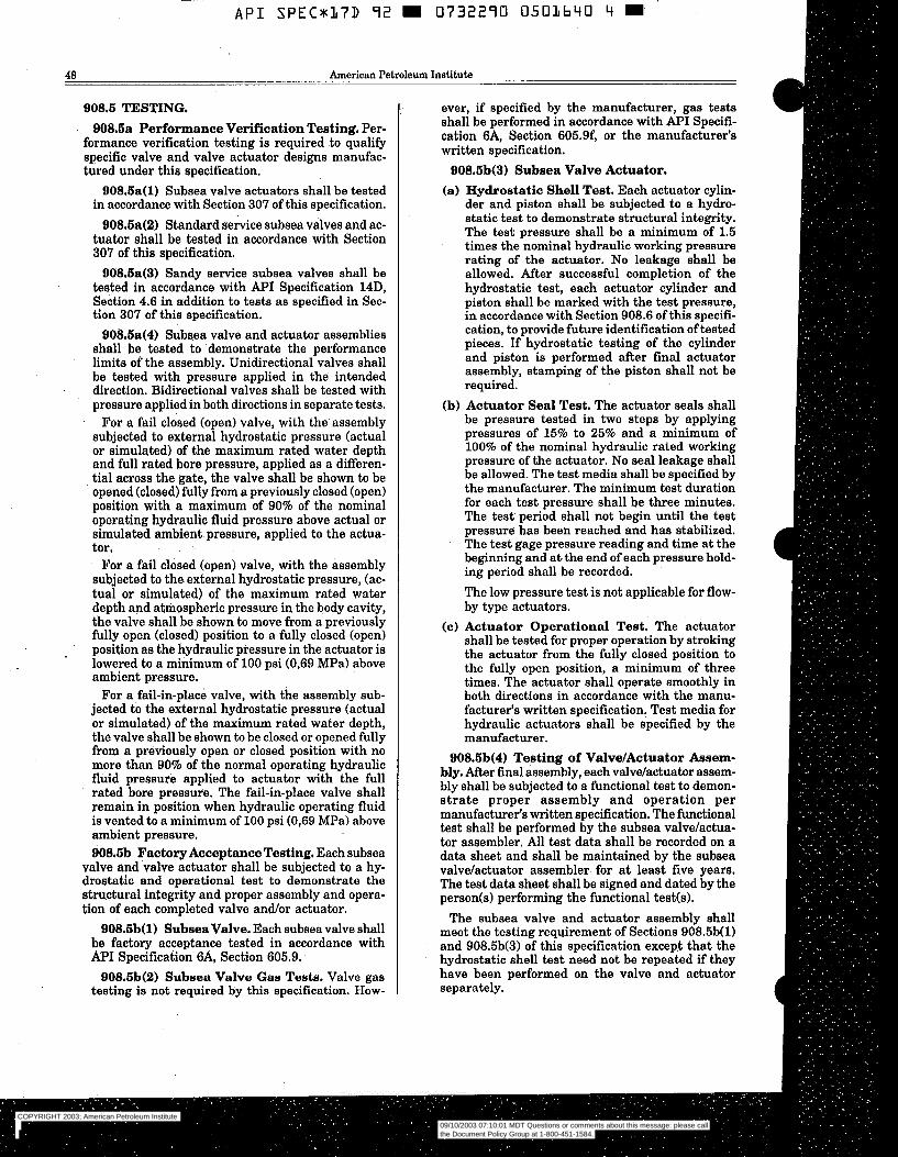
~
A P I SPECmL7D 92 m 0732290 0503640 4 m
48 American Petroleum Institute
908.5 TESTING. 908.6a Performance Verification Testing. Per-
formance verification testing is required to qualify specific valve and valve actuator designs manufac- tured under this specification.
908.6a(l) Subsea valve actuators shall be tested in accordance with Section 307 of this specification.
QOS.Sa(2) Standard sekce subsea valves and ac- tuator shall be tested in accordance with Section 307 of this specification.
QOS.Sa(3) Sandy service subsea valves shall be tested in accordance with API Specification 14D, Section 4.6 in addition to tests as specified in Sec- tion 307 o€ this specification.
DOS.Sa(4) Subsea valve and actuator assemblies shall be tested to demonstrate the performance limits of the assembly. Unidirectional valves shall be tested with pressure applied in the intended
- direction. Bidirectional valves shall be tested with pressure applied in both directions in separate tests.
For a fail closed (open) valve, with the assembly subjected to external hydrostatic pressure (actual or simulated) of the maximum rated water depth and full rated bore pressure, applied as a differen- tial across the gate, the valve shall be shown to be
. opened (closed) fully from a previously closed (open) position with a maximum of 90% of the nominal operating hydraulic fluid pressure above actual or simulated ambient pressure, applied to the actua- tor.
For a fail closed (open) valve, with the assembly subjected to the- external hydrostatic pressure, (ac- tual or simulated) of the maximum rated water depth and atmospheric pressure in the body cavity, the valve shall be shown to move from a previously fully open (closed) position to a fully closed (open) position as the hydraulic pressure in the actuator is
’ lowered to a minimum of 100 psi (0,69 MPa) above ambient pressure.
For a fail-in-place valve, with the assembly sub- jected to the external hydrostatic pressure (actual or simulated) of the maximum rated water depth, the valve shall be shown to be closed or opened fully from a previously open or closed position with no more than 90% of the normal operating hydraulic fluid pressure applied to actuator with the full rated bore pressure. The fail-in-place valve shall remain in position when hydraulic operating fluid is vented to a minimum of 100 psi (0,69 MPa) above ambient pressure. Q08.6b Factory Acceptance Testing. Each subsea
valve and valve actuator shall be subjected to a hy- drostatic and operational test to demonstrate the structural integrity and proper assembly and opera- tion of each completed valve and/or actuator.
908.6b( 1) Subsea Valve. Each subsea valve shall be factory acceptance tested in accordance with API Specification 6A, Section 605.9.
908.Sb(2) Subsea Valve Gas Tests. Valve gas testing is not required by this specification. How-
ever, if specified by the manufacturer, gas tests shall be performed in accordance with API Specifi- cation 6A, Section 605.9f, or the manufacturer’s written specification.
QOS.Sb(3) Subsea Valve Actuator. (a) Hydrostatic Shell Test. Each actuator cylin-
der and piston shall be subjected to a hydro- static test to demonstrate structural integrity. The test pressure shall be a minimum of 1.5 times the nominal hydraulic working pressure rating of the actuator. No leakage shall be allowed. After successful completion of the hydrostatic test, each actuator cylinder and piston shall be marked with the test pressure, in accordance with Section 908.6 of this specifi- cation, to provide future identification of tested pieces. If hydrostatic testing of the cylinder and piston is performed after final actuator assembly, stamping of the piston shall not be required.
(b) Actuator Seal Test, The actuator seals shall be pressure tested in two steps by applying pressures of 15% to 25% and a minimum of 100% of the nominal hydraulic rated working pressure of the actuator. No seal leakage shall be allowed. The test media shall be specified by the manufacturer. The minimum test duration for each test pressure shall be three minutes. The test period shall not begin until the test pressure has been reached and has stabilized. The test gage pressure reading and time at the beginning and a t the end of each pressure hold- ing period shall be recorded. The low pressure test is not applicable for flow- by type actuators.
(c) Actuator Operational Test. The actuator shall be tested for proper operation by stroking the actuator from the fully closed position to the fully open position, a minimum of three times. The actuator shall operate smoothly in both directions in accordance with the manu- facturer’s written specification. Test media for hydraulic actuators shall be specified by the manufacturer.
908.Sb(4) Testing of Valve/Actuator Assem- bly. After h a 1 assembly, each valve/actuator assem- bly shall be subjected to a functional test to demon- strate proper assembly and operation per manufacturer‘s written specification. The functional test shall be performed by the subsea valvelactua- tor assembler. All test data shall be recorded on a data sheet and shall be maintained by the subsea valve/actuator assembler- for at least five years. The test data sheet shall be signed and dated by the person(s) performing the functional test(s).
The subsea valve and actuator assembly shall meet the testing requirement of Sections 908.5b(1) and 908.5b(3) of this specification except that the hydrostatic shell test need not be repeated if they have been performed on the valve and actuator separately.
COPYRIGHT 2003; American Petroleum Institute
Document provided by IHS Licensee=Kellogg Borwn & Root/3262700001, User=, 09/10/2003 07:10:01 MDT Questions or comments about this message: please callthe Document Policy Group at 1-800-451-1584.
--`,,,``,```,`,`,``,`,,``,`,,`-`-`,,`,,`,`,,`---
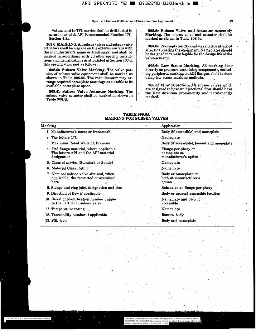
A P I S P E C * L ? D 92 0732290 0503643 b i ~ _*
Spec 17IX Subsea Wellhead and Christmas Tree Equipment ~~
49
Valves used in TFL service shall be drift tested in accordance with API Recommended Practice 17C, Section 4.3a.
908.6 MARKINGAU subsea valves and subsea valve actuators shall be marked on the exterior surface with the manufacturer’s name or trademark, and shall be marked in accordance-with all other specific instruc- tions and identifications as stipulated in Section 700 of this specification and as follows:
908.6~1 Subsea- Valve. Marking. The valve por- tion of subsea valve equipment shall be marked as shown in Table 908.6a. The manufacturer may ar- range required nameplate markinga as suitable to fit available nameplate space.
908.613 Subsea Valve Actuator Marking. The subsea valve actuator shall be marked a s shown in Table 908.6b.
90ä.6~ Subsea Valve and Actuator hsembly Marking. The subsea vaIve and actuator shall be marked as shown in Table 908.6~.
908.6d Nameplates. Nameplates shall be attached &er final coating the equipment. Nameplates should be designed to remain legible for the design life of the valve/actuator.
908.60 Low Stress Marking. All marking done directly on pressure con€aining components, exclud- ing peripheral marking on A P I flanges, shall be done using low stress marking methods.
908.6f Flow Direction. All subseá valves which äre designed to have unidirectional flow should have the flow direction prominently and permanently marked.
TABLE 908.6A MARKING FOR SUBSEA VALVES
Marking .Application 1. Manufacturer’s name or trademark Body (if accessible) and nameplate 2. The letters 17D - -Nameplate
3. Maximum Rated Working Pressure Body (if accessible), bonnet and nameplate 4. End flange material, where applicable. Flange periphery or
The letters API and the A P I material nameplate at designation manufacturer’s option
5. Class of service [Standard or Sandy] Nameplate 6. Material Class Rating Nameplate 7. Nominal subsea valve size and, when^
. -
Body or nameplate or applicable, the restricted or oversized both at manufacturer’s bore option
8. Flange and ring-joint designation and size Subsea valve flange periphery 9. Direction of flow if applicable Body or nearest accessible location
10. S e ~ a l or identification number uniqúe Nameplate and body if
11. Temperature rating Nameplate 12. Traceability number if applicable Bonnet, body - .
13. PSL level -- Body and nameplate
to the particular subsea valve . accessible
.~
. .
COPYRIGHT 2003; American Petroleum Institute
Document provided by IHS Licensee=Kellogg Borwn & Root/3262700001, User=, 09/10/2003 07:10:01 MDT Questions or comments about this message: please callthe Document Policy Group at 1-800-451-1584.
--`,,,``,```,`,`,``,`,,``,`,,`-`-`,,`,,`,`,,`---
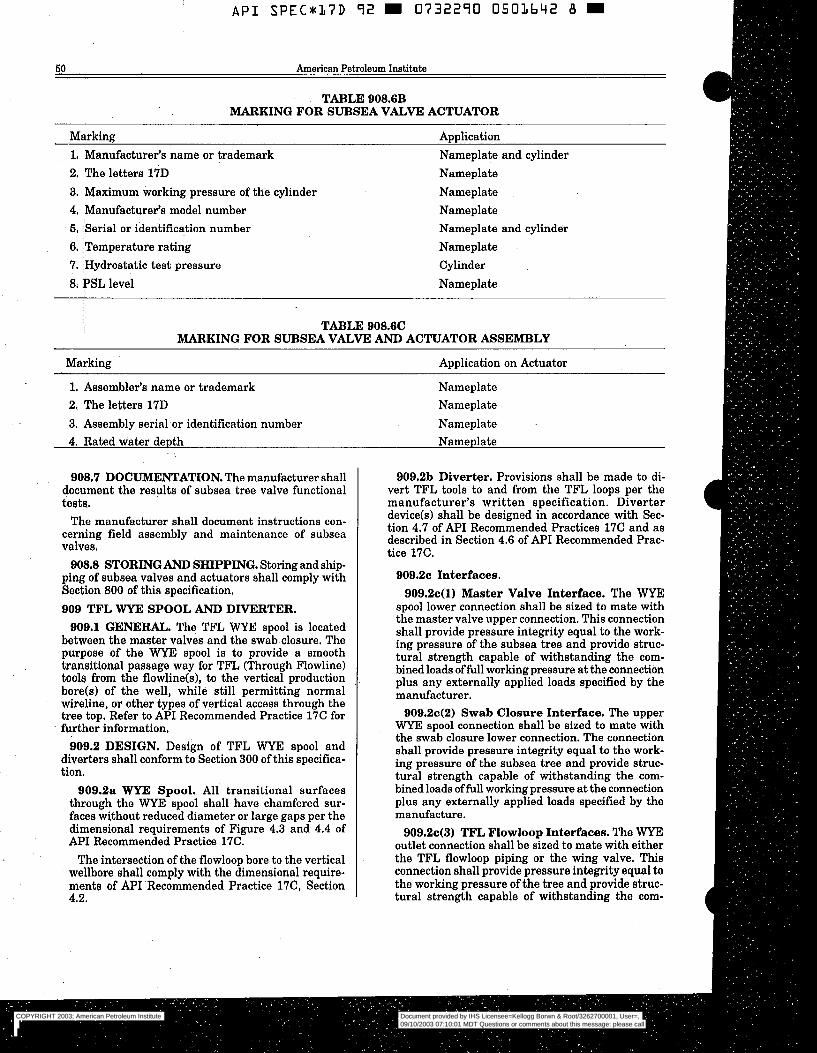
A P I SPEC*37D 92 m 0732290 0503642 B I
KO American Petroleum Institute
TABLE 908.6B MARKING FOR SUBSEA VALVE ACTUATOR
Marking Application 1, Manufacturer’s name or trademark Nameplate and cylinder 2. The letters 17D Nameplate 3. Maximum working pressure of the cylinder Nameplate 4. Manufacturer’s model number Nameplate 5. Serial or identification number Nameplate and cylinder 6. Temperature rating Nameplate 7. Hydrostatic test pressure Cylinder 8. PSL level Nameplate
TABLE 908.6C MARKING FOR SUBSEA VALVE AND ACTUATOR ASSEMBLY
Marking Application on Actuator
1. Assembler’s name or trademark Nameplate 2. The letters 17D Nameplate 3. Assembly serial -or identification number Nameplate 4. Rated water depth Nameplate
908.7 DOCUMENTATION. The manufacturer shall document the results of subsea tree valve functional testa.
The manufacturer shall document instructions con- cerning field assembly and maintenance of subsea valves.
ping of subsea valves and actuators shall comply with Section 800 of this specification. 909 TFL WYE SPOOL AND DIVERTER.
908.8 STORINGAND SHIPPING. Storingad ~hip-
909.1 GENERAL. The TFL WYE spool is located between the master valves and the swab closure. The purpose of the WYE spool is to provide a smooth transitional passage way for TFL (Through Flowline) tools from the flowline(s), to the vertical production bore(s) of the well, while still permitting normal wireline, or other types of vertical access through the tree top. Refer to API Recommended Practice 17C for further information,
909.2 DESIGN. Design of TFL W E spool and diverters shall conform to Section 300 of this specifica- tion.
909.2a WYE Spool. All transitional surfaces through the WYE spool shall have chamfered sur- faces without reduced diameter or large gaps per the dimensional requirements of Figure 4.3 and 4.4 of AF’I Recommended Practice 17C.
The intersection of the flowloop bore to the vertical wellbore shall comply with the dimensional require- ments of A P I Recommended Practice 17C, Section 4.2.
909.2b Diverter. Provisions shall be made to di- vert TFL tools to and from the TFL loops per the manufacturer’s written specification. Diverter device(s) shall be designed in accordance with Sec- tion 4.7 of AF’I Recommended Practices 17C and as described in Section 4.6 of API Recommended Prac- tice 17C.
909.2~ Interfaces. 909.2c(1) Master Valve Interface. The WYE
spool lower connection shall be sized to mate with the master valve upper connection. This connection shall provide pressure integrity equal to the work- ing pressure of the subsea tree and provide struc- tural strength capable of withstanding the com- bined loads of fidl working pressure at the connection plus any externally applied loads specified by the manufacturer.
909.2c(2) Swab Closure Interface. The upper WYE! spool connection shall be sized to mate with the swab closure lower connection. The connection shall provide pressure integrity equal to the work- ing pressure of the subsea tree and provide struc- tural strength capable of withstanding the com- bined loads of full working pressure at the connection plus any externally applied loads specified by the manufacture.
909.243) TF’L Flowloop Interfaces. The WYE outlet connection shall be sized to mate with either the TFL flowloop piping or the wing valve. This connection shall provide pressure integrity equal to the working pressure of the tree and provide struc- tural strength capable of withstanding the com-
COPYRIGHT 2003; American Petroleum Institute
Document provided by IHS Licensee=Kellogg Borwn & Root/3262700001, User=, 09/10/2003 07:10:01 MDT Questions or comments about this message: please callthe Document Policy Group at 1-800-451-1584.
--`,,,``,```,`,`,``,`,,``,`,,`-`-`,,`,,`,`,,`---
A P I SPECSKL7D 92 W 073-2290 0501b43 T W L ~ ""
Spec 17D: Subsea Wellhead and Christmas Tree Equipment 51
bined loads of full working pressure at the connec- tion plus any externally applied loads specified by the manufacturer, Combined pressure loading, pip- ing preloads (or tension), flowloop makeup and any other applied loads shall not exceed the allowable yield stress of the TFL piping as defined in Section 914 of this specification, nor shall i t reduce the flowline internal diameter to below the drift diam- eter. The bore of €he WYE spoor shall. be aligned with the bore of the flowloop according to the di- mensional requirements of API Recommended Prac- tice 17C, Section 4.2. Angles of the TFL-WYE spool/ flowloop connection shall be less than or equal to 15" from vertical.
909.2c(4) WYE SpooVDiverter Interface. The diverter bore should be concentric with the bore of the flowline and a smooth transitionsurface should be used to connect the bores. In-addition to the straight section ofthe flowloop above the transition surface, a straight section should alsö be provided above or below any locking recesá or side pocket. The internal surface should provide a smooth tran- sition from cylindrical passage to curvature of the loop.
909.3 MATERIALS. Material requirements shall conform with Section 400 of this specification. All end and outlet connections used on TFL Wye spools shall have their ring grooves either manufactured from, or-. inlayed with, corrosion resistant materials.
909.4 WELDING. Welding on TFL WYE spools and diverters shall conform to Section 500 of this specifica-. tion.
909.6 TESTING. All TFL WYE spools and dive~rters shall be tested in accordance with Section 600 of this specification and drift tested per API Recommended Practice 17C, Section 3.4a,
909.6 MARKING. All TFLWYE spools and diverters shall be marked to conform with Section 700 of this specification.
909.7 STORING AND SHIPPING. All TFL WYE spools and diverters shall be shipped and stored in accordance with Section 800 of this specification. 910 SUBSEA TREE UPPER CONNECTION AND
910.1 GENERAL. Section 910 addresses the upper terminations of the tree wellbores. The design and manufacture of control couplerdconnectors which may or may not be integral with the tree upper connection and/or the tree cap, are not addressed in this docu- ment.
SUBSEA TREE CAF'.
910.la Tree Upper Connection. 910.la(l) Purpose. To provide an uppermost at-
tachment interface on the tree for connection of: A tree running tool used for installation and
A tree cap. Internal crown plugs, if applicable.
"910.1a(2) Intena1 or Nonintegral. The tree upper connection may consist of a separate spool
workover purposes.
which mechanically connects and seals to the tree upper valve or upper valve block termination. The upper connectLon may consist of an integral inter- face profile in or-on top of the valve(s) body, 910.1b nee cap..
BlO.lb(1) Non-pressure ContainingTree Cap. Non-pressure containing tree caps protect the tree upper connection and vertical wellbores from pos- sible environmental damage or undesired effects resulting from corrosion, marine growth or poten- tial mechanical loads. Design of non-pressure con- taining tree caps shall comply *th Section 300 of this specification and is not addressed further in this document,
BlO.lb(2) Pressure Containing Tree Cap. A pressure containing tree cap provides tree top pro- tection and an additional sealing barrier between tree wellbore($ and the environment. . ~ .
910.2 DESIGN. . . _
910.2a General. This section applies to both the tree upper connection and pressure containing tree caps. The design of this equipment shall comply with Section 300 of this specification,
-910.2a(l) Pressure Rating. The tree upper cön- nection and tree cap shall be rated to the tree working-pressure plus an allowance for other load- ing effects as defined in Section 910.2b of this speci- fication.
910.2a(2) Tree Upper Termination .Connec- tionkofile. The tree upper connection shall pro- vide a locking and sealing profilé for the tree run- ning tool and/or tree cap. The design strength of the connection shall be based on loading considerations specified -in Section 910.2b of this specification. Independent sealing. surfaces shall be provided for each treebore. Corrosion resistant materials or in- lays shall be provided for these seal surfaces, Inlays are not required if the base metal is corrosion resistant or ifredundant nonmetallic seals are used, The connection shall also provide for passage of wireline bols and shall not limit the drift diameter of the treebore.
910.2a(3) Pressure Containing Tree Caps. The tree cap locking mechanism shall be designed to contain the rated tree working pressur-e acting over the corresponding seal areas that interface with the upper tree connection.
910.2a(4) Crow-Plug Profiles. The effect of wall thickness reductions due to crown plug pro- files machined into the tree upper termination shall be included in design analysis and documentation 8s required in Section 300 of this specification.
910.2b Design Loads/Conditions. Analytical design methods shall conform to Section 300 of this specification. As a minimum, the following loading parameters/conditions shall be considered and doumented by the manufacturer when designing the upper tree connection and tree cap:
Internal and external pressure
COPYRIGHT 2003; American Petroleum Institute
Document provided by IHS Licensee=Kellogg Borwn & Root/3262700001, User=, 09/10/2003 07:10:01 MDT Questions or comments about this message: please callthe Document Policy Group at 1-800-451-1584.
--`,,,``,```,`,`,``,`,,``,`,,`-`-`,,`,,`,`,,`---
A P I S P E C * l ’ Z D 9 2 m 0732290 0503644 L m
62 American Petroleum Institute
Pressure separation loads shall be based on worst case sealing conditions (leakage to the largest redun- dant seal diameter shall be assumed)
6 Mechanical preloads Riser bending and tension loads External environmental loads Fatigue considerations Mechanical installation (impact) loads Hydraulic coupler thrust andor preloads Corrosion 910.2~ Installation Pressure Test. A means shall
be provided to test the upper tree connection and tree cap sealb) after installation.
910.2d Pressure Venting, The tree cap shall be designed such that any pressure underneath the cap can be vented prior to cap release. This function may be designed to be automatic or to be performed inde- pendently,
910.28 Hydraulic Lock. A means shall be pro- vided for the prevention of hydraulic lock during installation of the tree cap.
910.2f Guidance and Orientation. Means shall be provided to guide and orient the tree cap relative to upper tree connection interface. 910.3 MATERIALS. Shall conform to Section 400 of
910.4 WELDING, Shall conform to Section 500 of
910.6 TESTING. 910.6a General, The following test procedure ap-
plies to upper tree connectors and tree cap connec- tors having either both mechanical or hydraulic con- nectors.
9lO.Sb Performance verification testing shall com- ply with the requirements of Section 307 of this specification.
910.60 Factory Acceptance Testing. All wellbore pressure containing/controlling components shall comply with the hydrostatic test requirements of Section 600 of this specification. Components having multiple bores or ports shall have each bore or port tested individually to verify that there is no inter- communication.
Components which contain hydraulic control fluid shall be subjected to a hydrostatic bodyhhell test per the requirements of Section 908.5b(3)(a) of this speci- fication.
After final assembly, the connector shall be tested for proper operation and interface per the manu- facturer’s written specification using actual mating equipment or an appropriate test fixture. Hydraulic circuits (if applicable) shall be subjected to a hydrostatic .test per the requirements of Section 908.5b(3)(b) of this specification.
Functional testing shall be conducted per the manufacturer’s written specification to verify the
this specification.
this specification.
primary and secondary operating and release mecha- nisms, override mechanisms, and locking mechanisms. Testing shall verify that actual operating forces/pres- sures fall within the manufacturer’s documented specifications. 910.6 MARKING. Shall conform to Section 700 of
this specification. 910.7 STORING AND SHIPPING. Shall conform
to Section 800 of this specification. 911 TREE GUIDE FRAME.
911.1 GENERAL. The tree guide frame interfaces with the permanent guide base to guide the subsea tree onto the subsea wellhead. The frame may also provide a structural mounting for piping, flowline con- nection, control interfaces, work platforms, anodes, handling points, and structural protection for tree com- ponents.
911.2 DESIGN. 911.2a Permanent Guide Base Interface. The
tree &de frame shall interface with standard per- manent guide base dimensions, refer to Figure 1001.2. Orientation of the guideline slots in the post shall be specified by the manufacturer.
911.2b Loads. As a minimum, the following loads shall be considered and documented by the manufac- turer when designing the tree guide frame:
Ballast Guideline Tension Flowline Reaction Loads Snag Loads
911.2~ Intervention Interfaces. Subsea interven- tion fixtures attached to the tree guide frame shall be in accordance with Section 921 of this specification. 911.3 MATERIALS. Materials shall conform to Sec-
tion 405 of this specification. 911.4 WELDING. Welding shall be in accordance
with Section 502 of this specification. 911.5 TESTING. Interface testing shall be conducted
on the guide frame by installing the frame on a four post 6.0 R. (1830 mm) radius test stump, or permanent guide base in compliance with Section 911.2a of this specification. A wellhead connector and mandrel or other centralizing means is to be used during the test. Test results shall be in accordance with the manufacturer’s written specifications.
911.6 MARKING. The marking shall conform to Section 700 of this specification.
ping shall be in accordance with Section 800 of this specification. 912 TREE RUNNING TOOL.
912.1 GENERAL. This section of the specification addresses the tree running tool as defined in API Recommended Practice 17A Section 2.3.2.3, Paragraph L. No attempt has been made to standardize dimen- sions of generic types of equipment.
911.7 STORINGAND SHIPPING. Storingandship-
COPYRIGHT 2003; American Petroleum Institute
Document provided by IHS Licensee=Kellogg Borwn & Root/3262700001, User=, 09/10/2003 07:10:01 MDT Questions or comments about this message: please callthe Document Policy Group at 1-800-451-1584.
--`,,,``,```,`,`,``,`,,``,`,,`-`-`,,`,,`,`,,`---
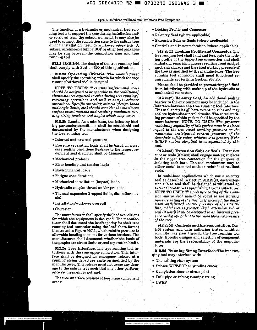
A P I SPECS17D 92 m 0732290 O501645 3 j ~~~ ~ ~~ ~
Spec 17D: Subsea Wellhead and Chri
The function of a hydraulic or mechanical tree run- ning tool is to support the tree during installation and/ or retrieval from the subsea wellhead. It may also be used to connect the completion riser to the subsea tree during installation] test, or -workover operations. A subsea wireline/coiltubing BOP or other tool packages may be run between the completion riser and tree running tool.
912.2 DESIGN. The design of the tree running tool shall comply with Section 300- of this specification.
912.2a Operating Criteria. The manufacturer shall specify the operating criteria for which the tree runninghetrieval tool is designed.
NOTE TO USERS: Tree runninglretrieval tools should be designed to be operable in the conditions1 circumstances expected to exist during tree running1 retrieving operations and well re-entry 1 workover operations. Specific operating criteria (design loads and angle limits, etc.) should consider the maximum surface vessel motions. and resulting maximum run- ning string tensions and angles which may occur.
912.2b Loads. As a minimum, the following load- ing parameters/conditions shall be -considered and documented by the manufacturer when designing the tree running tool.
Internal and external pressure Pressure separation loads shall be based on.worst case sealing conditions (leakage to the largest re- dundant seal diameter shall be assumed). Mechanical preloads Riser bending and tension loads Environmental loads Fatigue considerations Mechanical installation (impact) loads Hydraulic coupler thrust andor preloads Thermal expansion (trapped fluids, dissimilar met-
Installatioxdworkover overpull -
Corrosion The manufacturer shall specify theloaddconditions
for which the equipment is designed. The manufac- turer shall document the loadlcapacity for their tree . -
running tool connector using the load chart-format illustrated in Figure 907.1, which relates pressure to allowable bending moment for various tensions. The manufacturer shall document whether the basis of the graphs are stress limits or seal separation limits.
912.2~ Tree Interface. The tree running tool in- terfaces with the tree upper connection. This inter- face shall be designed for emergency release a t a running string departure angle as specified by the manufacturer. This release must nót cause any dam- age to the subsea tree such that any other perform- ance requirement is not met.
The tree interface consists of four main component
als)
areas:
istmas Tree Equipment 53
Locking Profile a i d Connector Re-entry Seal (where applicable) Extension Subs or Seals (where applicable) Controls and.Instrumentation (where applicable)
~. 912.20(1)~~ Locking Profile and Connector. The tree run@ng tao1 shall land a d l o c k onto the lock- ing profile of the upper tree connection and shall .withstand separating forces resulting from applied mechanical loads and the rated working pressure of-
- the tree as specified by the manufacturer. The tree running tool connector shall meet functional re- quirements set forth in Section 907.2b.
Means shall be provided to prevent trapped 5uid from interfering with make-up of the hydraulic or mechanical connector,
912.2c(2) Re-entry Seal. An additionäl eehng barrier ta the environment may-be included in the interface-between the tree running tool- interface. This seal encircles all bore extension subs. and may enclose hydraulic: control circuits. The rated work- ing pressure of this gasket shall be specified by the manufacturer. NOTE TO USER: The pressure containing capability of this gasket must be a t least equal to the tree rated working pressure or the maximum anticipated control. pressure of the downhole safety valve, whichever is greater, if the SCSSV. control circuitCs) is encapsulated by .this seal.
912.2c(3) Extension Subs or k A s . Extension subs or seals (if used) shall engage mating surfaces in the upper tree connection for the purpose of isolating each bore. The seal mechanism may be either metal-to-metal seals or redundant resilient seals.
In multi-bore applications which use a re-entry seal as described in Section 912.2c(2), each exten- sion sub or seal shallbe designed to withstand an external pressure as specified by the manufacturer. NOTE TO USER' The pressure rating of the exten- sion sub or seal should be equal to the working pressure rating of the tree, -os if enclosed, the maxi- mum anticipated control pressure of the SCSSV line, whichever i s - greater. Each extension sub or seal (if used) shall be designed to an internal pres- sure rating equivalent to the rated workingpressure of the tree.
912.2c(4) Controls andIwtrumentation. Con- trol system and data gathering instrumentation conduits may pass through the tree running tool body, Specific designs and selection of component materials are the responsibility of the manufac- turer. 91?,2d. Running String Interface. The tree run-^
ning tool may interface with The drilling riser system Subsea WCT-BOP or wireline cutter Completion riser or stress joint Drill pipe or tubing running string LWRP
COPYRIGHT 2003; American Petroleum Institute
Document provided by IHS Licensee=Kellogg Borwn & Root/3262700001, User=, 09/10/2003 07:10:01 MDT Questions or comments about this message: please callthe Document Policy Group at 1-800-451-1584.
--`,,,``,```,`,`,``,`,,``,`,,`-`-`,,`,,`,`,,`---
A P I SPEC*( /7D 92 S 0732290 0501646 5 R!!
64 American Petroleum Institute
912.28 Tree Guideframe Interface. The tree run- ning tool may have a guidance structure that inter- faces with the tree guideframe to provide initial orientation and alignment. If a guidance system is used, it shall be designed to provide alignment to protect seals and seal surfaces from damage in ac- cordance with the manufacturer’s written specifica- tion.
912.2f Control System Interface. The tree run- ning tool and/or the workover control interface nor- mally transfers control of the subsea tree from the normal surface production control point to the workover control system. 912.3 MATERIALS. Tree running tool portions
which may be exposed to wellbore fluids shall be made of materials conforming to Section 400 of this specifi- cation and to NACE MR-01-75. Structural materials shall conform to the requirements of Section 400.
with Section 500 of this specification. 912.4 WELDING. Welding shall be in accordance
912.6 TESTING. 912.6a General. The following test procedure ap-
plies to both mechanical and hydraulic connectors. 912.6b Performance verification testing shall com-
ply with the requirements of Section 307 of this specification.
9i2.6~ Factory Acceptance Testing. All wellbore pressure containinghontrolling components shall comply with the hydrostatic test requirements of Section 600 of this specification. Components having multiple bores or ports shall have each bore or port tested individually to verify that there is no.inter- communication.
Components which contain hydraulic control fluid shall be subjected to a hydrostatic bodyhhell test per the requirements of Section 908.5b(3)(a) ofthis speci- fication.
After final assembly, the connector shall be tested for proper operation and interface per the manu- facturer’s written specification using actual mating equipment or an appropriate test fixture. Hydraulic circuits (if applicable) shall be subjected to a hydrostatic test per the requirements of Section 908,5b(3)(b) of this specification.
Functional testing shall be conducted per the manufacturer’s written specification to verify the primary and secondary operating and release mecha- nisms, override mechanisms, and locking mechanisms. Testing shall verify that actual operating forces/pres- sures fall within the manufacturer’s documented specifications. 912.6 MARKING, Identification of each component
shall be in accordance with Section 700 of this specifi- cation.
912.7 STORINGAND SHIPPING. Storingand ship- ping shall be in accordance with Section 800 of this specification. 913 TREE CAP RUNNING TOOL,
913.1 GENERAL. Tree cap running tool is used to . install and remove subsea tree cap assemblies. Tree
cap running tools may be mechanically or hydraulical- ly operated.
Tools for running tree caps may have some of the following functions:
actuation of the tree cap connector pressure tests of the tree cap seals
relieve pressure beneath the tree cap injection of corrosion inhibitor fluid
ply with Section 300 of this specification. 913.2 DESIGN. The tree cap running tool shall com-
913.2a Operating Criteria. The tree cap running tool shall have operating criteria as set forth in Section 912.2a of this specification.
913.2b Loads. Design loads shall be determined and documented in the same manner as set forth in Section 912.2b of this specification.
913.2~ Tree Cap to Running Tool Interfaces.
913.2c(l) The interface between the tree cap and running tool shall be designed for release at a running string departure angle as documented by the manufacturer. This release must not cause any damage to the subsea tree such that any other performance requirement is not met.
913.2c(2) For pressure containing tree caps, any interface connections of related piping, hoses, and valves which could communicate with the seal cav- ity shall be designed to withstand internal and external pressures as described in Section 912.2 of this specification.
913.3 MATERIALS. Materials selection shall con- form to Section 400 of this specification.
913.4 WELDING. Welding requirements shall con- form to Section 500 of this specification.
913.6 TESTING.
913.6a General. The following test procedure ap- plies to both mechanical and hydraulic connectors.
913.6b Performance verification testing shall com- ply with the requirements of Section 307 of this specification.
913.6~ Factory Acceptance Testing. All wellbore pressure containing/controlling components shall comply with the hydrostatic test requirements of Section 600 of this specification. Components having multiple bores or ports shall have each bore or port tested individually to verify that there is no inter- communication.
Components which contain hydraulic control fluid shall be subjected to a hydrostatic bodyhhell test per the requirements of Section 908.5b(3)(a) of this speci- fication.
After final assembly, the connector shall be tested for proper operation and interface per the manu- facturer’s written specification using actual mating equipment or an appropriate test fixture. Hydraulic
COPYRIGHT 2003; American Petroleum Institute
Document provided by IHS Licensee=Kellogg Borwn & Root/3262700001, User=, 09/10/2003 07:10:01 MDT Questions or comments about this message: please callthe Document Policy Group at 1-800-451-1584.
--`,,,``,```,`,`,``,`,,``,`,,`-`-`,,`,,`,`,,`---
~~~- ~ ~ "
..
Spec 17D: Subsea Wellhead and%hristmaa Tree Equipment 66
circuits (if applicable) shall be subjected to a hydrostatic test per the requirements of Section 908.6b(3)(b) of this specification.
Functional testing shall be conducted per the manufacturer's written specification to verify the primary and secondary operating and release mecha- nisms, override mechanisms, and locking mechanisms. Testing shall verify that actual operating forcedpres- sures fall within the manufacturer's. documented specifications. 913.6 MARKING. Cömponent marking. shall con-
form to Section 700 of this specification. 913.7 STORING AND SHIPPING. Storing and
shipping shall conform to Section 800 of this specifica- tion. 914 TREE PIPING.
914.1 GENERAL. Tree piping is defined a i all pipe, fittings, or pressure conduits, excluding valves and chokes, from the vertical bores of the tree to the flowline connection(ä) leaving the subsea tree. The piping may be used for production, pigging, monitoring, injection] service, or test of the subsea tree.
Inboard tree piping is upstream of the first tree wing valve(s). Outboard tree piping is downstream of the first tree wing valve, and upstream of the flowline connector.
914.2 DESIGN. 914.2a Allowable Stresses. öutboard-tree pip-
ing shall conform to the requirements of an exisfing documented piping code, such a8 ANSUASME Ë31.4, B31.8 or B31.3. As a minimum, the design rated working pressure of the outboard piping shall be equal to the rated working pressure. of the tree. Inboard piping shall be designed in accordance with Section 300 of this specification. In all cases, the following shall be considered:
Allowable stress at working pressure Allowable stress at test pressure External loading Tolerances CorrosiodErosion allowance Temperature Wall thinning due to bending -
914.21, Other End Connectors. Other end con- nectors shall comply with Sections 901 through 906 of this specification.
914.2~ Operating Parameters. Operating param- eters for tree piping shall be based on the service, temperature] material, and external loading on each line. Tree piping may be designed to flex to enable connectors to stroke or to compensate for manufac- turing tolerances.
914.2d Tree Piping Flowloops. Tree piping flowloops may be fabricated using forged fittings or prebent sections, or may be formed in a continuous piece. Either "cold" bending or "hot" bending may be used. Bends which are to be used in H,S service shall conform to the requirements of NACE MR-01-75.
COPYRIGHT 2003; American Petroleum Institute
Document provided by IHS Licensee=Kellogg Borwn & Root/3262700001, User=, 09/10/2003 07:10:01 MDT Questions or comments about this message: please callthe Document Policy Group at 1-800-451-1584.
--`,,,``,```,`,`,``,`,,``,`,,`-`-`,,`,,`,`,,`---
A P I SPEC*17D 7 2 m 0732270 0501648 7 m
66 American Petroleum Institute
914.7 STORING AND SHIPPING. Storing and Shipping shall be in accordance with Section 800 of this specification.
916 FLOWLINE CONNECTOR SYSTEMS.
916.1 GENERAL - TYPES AND USES. This sec- tion covers the flowline connector systems which are used to connect subsea flowlines and umbilicals to subsea trees. Electrical connection and component equipment is beyond the scope of this specification.
The flowline connector system may utilize various installation methods, such as first end or second end connection methods as described in API Recommended Practice 17A, Section 3. Flowline connectors may be either diverless or diver-assisted and may utilize guide- lines/guideposts to provide guidance and alignment of the equipment during installation. Guidelineless sys-
. tems are beyond the scope of this specification.
916.2 FLOWLINE CONNECTOR SUPPORT FRAME.
916.2a General - The flowline connector support frame provides a structural attachment to the subsea tree and/or subsea wellhead which will receive the flowline connector mechanism. The support frame may be attached to the subsea wellhead housing, the permanent guide base, the tree and/or tree frame, the template frame (if applicable), or other suitable structural member.
916.2b Design. 916.2b(l) Loads - The following loads shall be
considered and documented by the manufacturers when designing the flowline connector support frame:
Flowline pull-in, catenary, andor drag forces dur- ing installation. Flowline alignment loads (rotational, lateral, and axial during installation). Flowline operational reaction loads due to re- sidual stresses, flowline weight, thermal expan- siodcontraction and operational/environmental effects. Flowline reactiodalignment loads when the tree is removed for service. Overloads, such as snag loads, mudslides, etc. 916.2b(2) Dimensions -The flowline connector
support frame should be designed to allow landing a BOP stack on the wellhead housing after the flowline connector support frame is installed.
916.2b(3) Functional Requirements - The flowline connector support frame shall be designed in accordance with Section 300 of this specification. 1t.should react all loads imparted by the flowline and umbilical into a structural member to ensure that:
Tree valves and/or tree piping are protected from flowline/umbilical loads which could damage these components.
Alignment of critical mating components is pro-
Tree can be removed and replaced without dam- vided and maintained during installation.
age to critical mating components. 916.3 FLOWLINE CONNECTORS.
916.3a General. The flowline connector and its associated running tools provide the means for join- ing the subsea flowline(s) and/or umbilical(s) to the subsea tree. In some cases, the flowline connector also provides means for disconnecting and removing the tree without retrieving the subsea flowlinelumbil- ical to the surface.
Flowline connectors generally fall into three cat- egories: 1) Manual connectors operated by divers or ROV's, 2) Hydraulic connectors with integral hy- draulics similar to subsea wellhead connectors, 3) Mechanical connectors with the hydraulic actuators contained in a separate running tool.
916.3b Design. Flowline connectors shall have a rated working pressure equal to the rated working pressure of the tree. The design of flowline con- nectors shall be in accordance with Section 300 of this specification with the exception that the pres- sure testing shall comply with Section 600 of this specification for a connector mounted inboard of the first wing valve. For a connector mounted outboard of the first wing valve, pressure testing shall comply
ANSVASME B31.4, B31.8 or B31.3. with an existing documented piping code such as
915.3b(1) Loads - The following loads shall be considered and documented by the manufacturer when designing the flowline connector and associ- ated running tools:
Flowline pull-in, catenary, and/or drag forces during installation. Flowline alignment loads (rotational, lateral, and axial) during installation. Flowline reaction loads due to residual stresses, flowline weight, thermal expansiodcontraction and operationallenvironmental effects. Reactions from environmental loads on flowline connector runninglretrieval and maintenance tools. Flowline reactiodalignment loads when the tree is pulled for service. FlowlineIUmbilical overloads. Internal and external pressures (Operational and HydrostatidGas Tests). The flowline connector shall ensure sealing under
all pressure and external loading conditions speci- fied.
When actuated to the locked position, hydraulic flowline connectors shall remain self-locked with- out requiring hydraulic pressure to be maintained. Connectors should be designed to prevent loosen- ing due to cyclic installation andor operational loading.
COPYRIGHT 2003; American Petroleum Institute
Document provided by IHS Licensee=Kellogg Borwn & Root/3262700001, User=, 09/10/2003 07:10:01 MDT Questions or comments about this message: please callthe Document Policy Group at 1-800-451-1584.
--`,,,``,```,`,`,``,`,,``,`,,`-`-`,,`,,`,`,,`---

Spec 17D: Subsea Wellhead and Christmas "rei Equipment - - ~~ 6 7
916.3b(2) Dimensions -The dimensions of the flowline connectors flow passages should be compati- ble with the drift diameters of the flowl-ines. - -
If TFL service is-specified, the TFL flow passage geometry shall meet the dimensional requirements of API Recommended Practice 17C,
If pigging capability is specified, the flowline con- nector flow passages should be configured to pro; vide transitions and internal geometry compatible with the type of pida) specified by the manufac- turer.
The end connections used on the flowline-connec- tor (flanges, clamp hube, or-other.types of connec- tions) shall comply with Sections 901 through 906 of this specification. Preparations for welded énd~ connections shall comply with Section 901.2 of this specification.
The termination interface between the flowline connector and the flowline shall conform to the- requirements of a documented design code, such as ANSI B31.3, B31.4, or B31.8. - - ~ ~
916.3b(3) Functional Requirements --. .The flowline connector and/or its associated running tool(s) should provide positioning and alignment of mating components such that cönnection can be accomplished without damage to sealing compo- nents or structural connection devices. Seals and sealing surfaces should be protected during flowline installation operations. -
Metal-to-metal seals are preferred for primary seals on flowline connectors. Where metal-to-metal primary seals are not utilized, redundant seals (pri- mary plus backup) shall be provided.
Where multiple bore seals are enclosed within an outer environmental ör secóndary seal, bi-direc- tional bore seals shall be provided h. prevent cross- communication between individual bores;
The flowline connection system shall provide means for pressure- testing the flowline and/or umbilical connections following installation and hookup.
The flowline connector design should provide- a means to disconnect and r.em6ve the tree (and to subsequently replace it) without the need fi re- . trieve the subsea flowlindumbilical to the surface. Consideration should be given preventing sea- water from entering into the flowline when sepa- rated from the tree.
'Ï'he flowline connector shall have the samework- ing pressure rating as the subsea tree. Means shall be provided for pressure testing the tree anda11 it8 associated API valves and chokes without exceed- ing the test pressure rating of the flowline connec- tor.
The flowline connector shall have the same tem- perature rating as the subsea tree.
916.4 MATERIALS. Flowline connector support frames may be of welded conetruction using common structural steels that conform to Section 400 of this specification.
COPYRIGHT 2003; American Petroleum Institute
Document provided by IHS Licensee=Kellogg Borwn & Root/3262700001, User=, 09/10/2003 07:10:01 MDT Questions or comments about this message: please callthe Document Policy Group at 1-800-451-1584.
--`,,,``,```,`,`,``,`,,``,`,,`-`-`,,`,,`,`,,`---
A P I SPECxL7D 92 0732290 0 5 0 3 6 5 0 7 m
68 American Petroleum Institute
the requirements of Section 908.5b(3)(a) of this speci- fication.
After final assembly, the connector shall be tested for proper operation and interface per the manu- facturer’s written specification using actual mating equipment or an appropriate test fixture. Hydraulic circuits (if applicable) shall be subjected to a hydro- static test per the requirements of Section 908.5b(3)(b) of this specification.
Functional testing shall be conducted per the manufacturer’s written specification to verify the primary and secondary operating and release mecha- nisms, override mechanisms, and locking mechanisms. Testing shall verify that actual operating forcedpres- sures fall within the manufacturer’s documented specifications.
Running Tools -All runninglretrieval and mainte- nance tools shall be tested per the manufacturer’s written specification for fit and function with mating equipment or test fixtures.
916.6d In-Situ Testing - In-Situ testing is be- yond the scope of this specification. However, if In- Situ testing of flowlines is required at pressures above the tree rated working pressure, a test isola- tion valve with a higher working pressure than the tree may be required. 916.7 MARKING. Marking shall comply with Sec-
tion 700 of this specification. 916.8 STORING AND SHIPPING. Storing and ship-
.ping shall comply with Section 800 of this specifica- tion, 916 CONTROL PACKAGE (POD) RUNNING/RE-
TRIEVAL AND TESTING TOOLS. 016.1 GENERAL. The Control Package Running/
Retrieval and Testing Tools are used to install, re- move, and test the subsea components of the produc- tion control system. The design of these tools is depen- dent upon the type of control system utilized and the configuration of the subsea hardware which may in- clude a control pod and hydraulic accumulator system (Refer to A P I Recommended Practice 17A Section 4.4.3).
Tools for running and retrieving the equipment will generally require hydraulic control functions to oper- ate lockdown devices, hydraulic or electrical connector actuation mechanisms, and means for connection to and release from the control package. Additional equip- ment may be included to provide the capability for inplace troubleshooting or fault isolation.
The tools may be run on a completion riser, drill pipe, wire rope, or umbilical.
916.2 DESIGN. The control package (POD) run- ninghetrieval and testing tool shall comply with Sec- tion 300 of this specification.
916.2a Operating Parameters. The manufacturer shall document the operating criteria for which the control package (POD) runninglretrieval and testing tools are designed. Specific operating criteria for the control package runninglretrieval and testing tools
shall be derived in the same manner specified in Section 912.2a of this specification.
916.2b Running Tool Interface. The manufac- turer shall document the maximum combined loads at which the running tool can remain connected with- out damage to the extent that any other performance requirement is not met. The running tool shall be designed for emergency release at running string tensions and departure angles as specified and docu- mented by the manufacturer.
Control and/or test connections which pass through this interface shall retain pressure integrity under the maximum combined loads rating.
916.2~ Control Package Guideframe. If used, guideframes on the control package and/or running tool shall be designed to provide for the alignment of mating components during installation and removal in accordance with the manufacturer’s written speci- fication.
916.3 MATERIALS. Materials selection shall con-
916.4 WELDING. Welding requirements shall con- form to Section 400 of this specification.
form to Section 500 of this specification. 916.6 TESTING. Testing requirements shall con-
form to Section 600 of this specification. 916.6 MARKING. Component marking shall con-
form to the requirements of Section 700 of this speci- fication.
916.7 STORING AND SHIPPING. Storing and ship- ping shall conform to the requirements of Section 800 of this specification. 917 FLOWLINE CONNECTOR SUPPORT FRAME
RUNNING/RETRIEVING TOOLS AND RELATED SYSTEM INTERFACES.
917.1 GENERAL. This section covers tools used to install and retrieve flowline connector support frames which are not installed integral with other equipment.
917.2 DESIGN. The design of these running tools shall comply with Section 300 of this specification.
917.2a Operating Criteria. The manufacturer shall document the operating criteria for which the flowline connector support from runninghetrievel tools and related system interfaces are designed. Specific operating criteria for the flowline connector support frame running tool shall be derived in the same manner specified in Section 912.2a ofthis speci- fication.
917.2b Loads and Component Strength. Design loads of the flowline connector support frame run- ning tool shall be determined in the manner specified in Section 912.2b of this specification.
917.2~ Running Tool Interfaces. The flowline connector support frame running tool shall be ca- pable of connection, function and disconnection at the maximum combined loads, as specified by the manufacturer.
COPYRIGHT 2003; American Petroleum Institute
Document provided by IHS Licensee=Kellogg Borwn & Root/3262700001, User=, 09/10/2003 07:10:01 MDT Questions or comments about this message: please callthe Document Policy Group at 1-800-451-1584.
--`,,,``,```,`,`,``,`,,``,`,,`-`-`,,`,,`,`,,`---
Spec 17D: Subsea Wellhead and Chri&mas Tree Equipment 69
Control andlor test connections which pass through the interface shall retain pressure integrity at the maximum combined load rating.
917.2d Guidance and Alignment. If used, guid- ance structures shall be designed to provide for align- ment of mating components during installation and removal in accordance to the manufacturer's written specification.
917.28 Remote Intervention Equipment. Re- mote intervention fixtures shall be deaigned in ac- cordance with requirementa of Section 921 of this specification.
917.3 MATERIALS. Materials shall conform to Sec- tion 400 of this specification.
917.4 WELDING. Welding requirements shall con- form to Section 600 of this specification.
917.5 TESTING. Test of flowline connector support frame running tool shall conform with Sections 300 and 600 of this specification.
917.6 MARKING. The flowline connector support frame running tool shall be marked to conform with Section 700 of this specification.
917.7 STORING AND SHIPPING. The flowline connector support frame running tool shall be stored and shipped in accordance with Section 800 of this specification. 918. TREE-MOUNTED H Y D R A U L I C CONTROL
INTERFACES 918.1 GENERAL. Tree-mounted hydraulic control
interfaces covered by this specification include all pipes, hoses, fittings, or connectors mounted on the subsea tree, flowline base, or associated runninghetrieving tools for the purpose of transmitting hydraulic signals or hydraulic power between controls, valve actuators and monitoring devices on the tree, flowline base or running tools and the control umbilical(s) or riser paths.
918.2 DESIGN.
918.2a PipeRLbinglHoses. Allowable stresses in pipehubing shall be in conformance with ANSI B31.3. Hose design shall conform to an existing documented industry standard such as SAE Standard 5517. De- sign shall take into account: . .
Allowable stresses at working pressure Allowable stresses at test pressure External loading Collapse Manufacturing tolerances Fluid compatibility Flow rate Corrosioderosion Temperature range
nominal diameter, or larger. 918.2b All pipdtubinghose shall be l/4" (6 m)
918.2~ Ail pipdtubinghose shall be within the en- velope .defined by the guideframes of the- tree, run- ninghetrieving tool, or the flowline base.
9.18.2d All pipdtubinghose should be supported and protected to~minimize damage during testing, installatiodretrieval, and normal operations of the subsea tree.
918.28 .End Fittings, Connectom, Connector Plates. End fittings and connectors shall meet or exceed requirements of the existing piping code used for the pipingltubinghose design in Section 918;2a of this specification.
The connector plateljunction plate assembly shall be designed to withstand rated working pressure applied simultaneously in every control path without deforming to the extent that any other performance requirement is not met- in accordance with the manufacturer's h t t e n specification. In addition, when non-pressure balanced control stabs are used, the manufacturer shall determine and'document the rated water depth a t which connector plate/junction plate can decouple the control stabs without defor- mation damage to the plate assemblies. The manu- facturer shall determine and document the force re- quired for decoupling at rated water depth.
Proprietary connector plateljunction plate designs shall meet the test requirements set forth in Section 918.4 of this specification.
918.2f Control Line Stabs. As a minimum, con- trol line stabs for the SCSSV, Production Master Valve(& Production Wing Valve, and- an Annulus Valve shall be designed so as not to- trap pressure when the control stabs are separated. The control stabs should be designed to minimize seawater in- gress when disconnected. In addition to the internal working pressure, the control stabs shall be designed to withstand external hydrostatic pressure ät manufacturer's rated water depth. 918.3 MATERIALS.
918.3a Pipdtubing and end fittings, connectors and connector plates shall be made of materials which conform to Section 400 of this specification. ~ ~
Pipehubinghoses which are not isolated from wellbore fluids by either. at least two barrierdseals or other appropriate means, shall be designed and ma- terials selected for exposure to wellbore fluids and pressures.
918.3b Seal materials used in the end fittings and connectors shall conform to Section 400 of this speci- fication. 918.4 TESTING,
918.4a Pipdtubing shall be of a design which has been performance verification teeted in conformance to ANSI B31.3. Hoses shall be of a design which has been performance^ verification tests in conformance to SAE -5343. Performance verification testing for hoses shall be repeated for hose designs whose verification test are more than five years old.
Testing of assembled pipdtubinghose and end fit- tings, connectors, and connector plates shall conform
COPYRIGHT 2003; American Petroleum Institute
Document provided by IHS Licensee=Kellogg Borwn & Root/3262700001, User=, 09/10/2003 07:10:01 MDT Questions or comments about this message: please callthe Document Policy Group at 1-800-451-1584.
--`,,,``,```,`,`,``,`,,``,`,,`-`-`,,`,,`,`,,`---
API SPEC*KL7D 72 m 0732290 050Lb52 O m
80 American Petroleum Institute
to Section 600 of this specification, except that the - ~" test pressure shall not exceed the test pressure of the
1õTeàt prëssÜrëÏ&ëd- component in the system. 918.413 The connector plate/junction plate assem-
bly shall be tested with rated working pressure ap- plied simultaneously in every control path in accor- dance with the manufacturer's written specification. .918.6 MARKING.
918.6a Cpmponent marking shall conform to ap- plicable requirements set forth in Section 700 of this specification.
918.6b Each connector plate shall be permanently marked with the following minimum information:
Its part number and the part number of the connec- tor plate it is designed to mate with, for example: "(Part number) TO MATE WITH (part number of mating plate)" Path designation numbers or letters identifying each pathlconnector in the connector plate assem- bly (Hoses and Tubing should be marked accord- ingly). Rated operating pressures of each path passing through the connector plate assembly, for example: 6 X 3000 PSI (20,7 MPa) - PATHS 1 - 6 4 X 1500 PSI (10,3 MPa) - PATHS 7, 8, 11,12 2 X 6000 PSI (34,6 MPa) - PATHS 9,10
918,tl STORINGAND SHIPPING. Storingand ship- ping shall conform to Section 800 of this specification. 919 SUBSEA CHOKES AND ACTUATORS.
919.1 GENERAC. This section covers subsea chokes, actuators, and their assemblies used in subsea applica- tions. It provides requirements for the choke/actuator assembly performance standards, sizing, design, mate- rials, testing, marking, storage and shipping. Subsea choke applications are production, gas lift, and injec- tion. Chokes are a special kind of control valve de- signed to control flow or pressure and are not intended to be used as shutoff valves.
Subsea chokes are considered high wear items and therefore allowances for choke maintenance should be considered. Subsea chokes may be designed for chang- ing flow bean or trim by divers or ROV/running tools. Placement of the choke should allow adequate spacing for retrieval,. and diver/ROV override operations.
919.2 SUBSEA CHOKES. 919.2a General.
919.2a(l) Adjustable Chokes. Adjustable chokes have an externally controlled variable-area orifice trim and may be coupled with an orifice area indicating mechanism.
919.2a(2) Positive Chokes. Positive chokes ac- commodate replaceable parts having a fixed orifice dimension, commonly known as flow beans.
919.2a(3) Orifice Configuration. "Orifice Con- figuration" for chokes, sometimes referred to as
"trim," in control valve terminology, describes the internal components which determine flow area through the choke. A variety of orifice configura- tions are available for chokes. Five of the most common adjustable orifice configurations are: ro- tating disc, needle and seat, plug and cage, sliding sleeve and seat, and multistage. Examples of orifice configurations are shown in Figure 919.1. Opti- mum orifice configuration is selected on the basis of operating pressures, temperatures and flow media.
919.2a(4) Choke Capacity. "he manufacturer shall document flow rate based on maximum ori- fice, pressure, temperature and fluid media.
The choke orifice diameter should be sized for anticipated or actual production flow rate and fluid conditions (pressures and temperature). The infor- mation shown in Appendix A for Purchasing Guide- lines should be supplied to the choke manufacturer for sizing of the choke. 919.2b Design. Subsea chokes shall be designed
in accordance with the general design requirements of Section 300 of this specification and Section 909.2 of API Specification 6A, as required for PR2.
Manufacturers shall document the design and operating parameters of the choke as listed in Table 919.1 of this specification.
TABLE 919.1 DESIGN AND OPERATING PARAMETERS OF
SUBSEA CHOKES Manufacturer (Name and Location) Model Number Maximum Pressure Rating Maximum Orifice Size Temperature Rating
Maximum Minimum
API PSL Level API Material Class Type of Choke
Positive (Fixed, Insert Type) Adjustable Choke with Handwheel Adjustable Choke Prep. for Manual Actuator Adjustable Choke Prep. for Hydraulic Actuator
End Connections Size and Pressure Rating (API) API Ring Gasket Size (If Applicable)
Type of Operation ROV Diver Assist Size of Socket or Hex (If Applicable) Handwheel Diameter
External Pressure Rating (Maximum) or Water Depth Maximum Flow Rate
COPYRIGHT 2003; American Petroleum Institute
Document provided by IHS Licensee=Kellogg Borwn & Root/3262700001, User=, 09/10/2003 07:10:01 MDT Questions or comments about this message: please callthe Document Policy Group at 1-800-451-1584.
--`,,,``,```,`,`,``,`,,``,`,,`-`-`,,`,,`,`,,`---
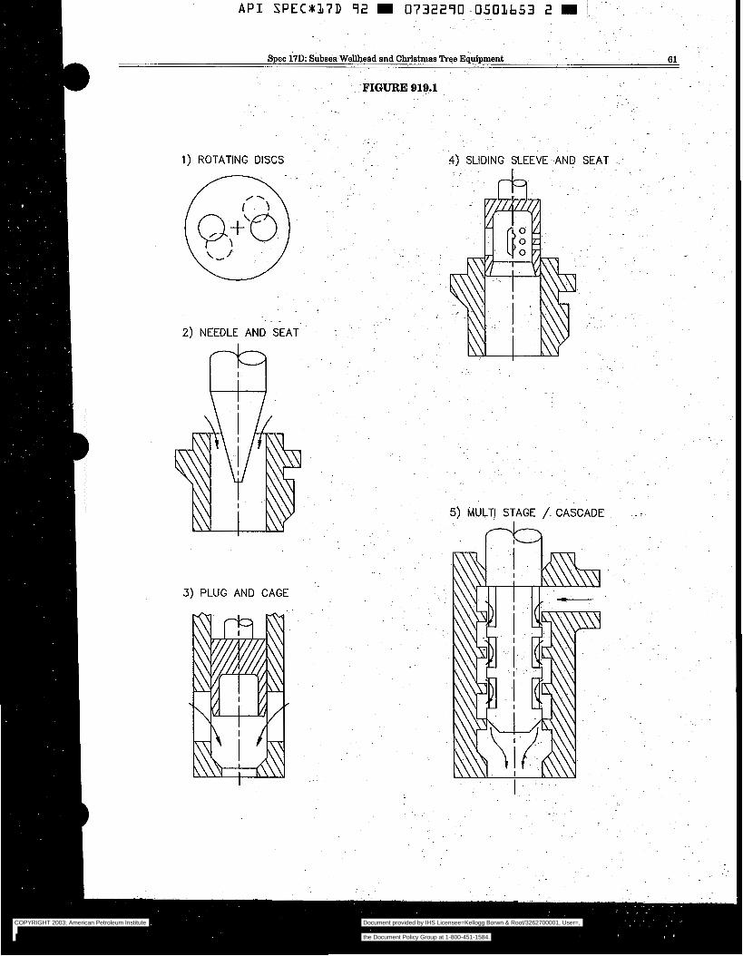
Spec 17D: Subsea Wellhead and Christmas Tree Equipment 61 .~
~ -FIGURE 919.1
1) ROTATING DISCS
2) NEEDLE AND SEAT
. .
I
3) PLUG AND CAGE
4) SLIDING SLEEVE AND SEAT
5) MULTI STAGË /. CASCADE
da
COPYRIGHT 2003; American Petroleum Institute
Document provided by IHS Licensee=Kellogg Borwn & Root/3262700001, User=, 09/10/2003 07:10:01 MDT Questions or comments about this message: please callthe Document Policy Group at 1-800-451-1584.
--`,,,``,```,`,`,``,`,,``,`,,`-`-`,,`,,`,`,,`---
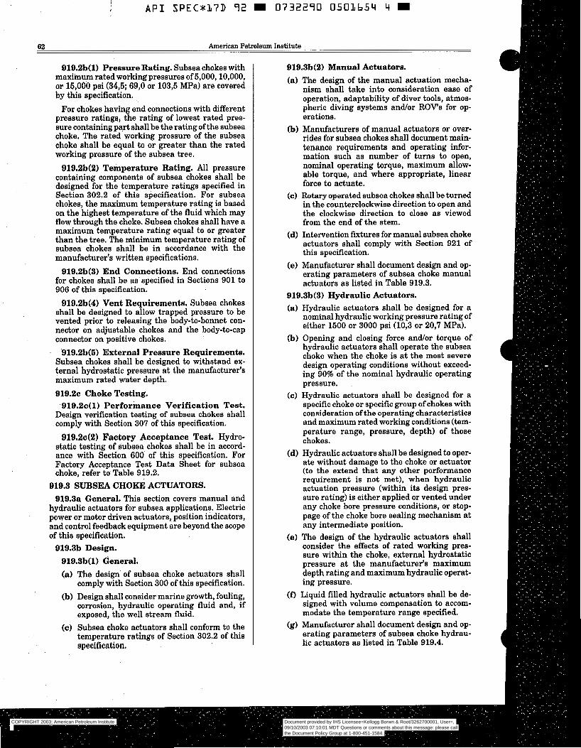
A P I S P E C * 3 7 D 92 m 0732290 O503654 4 m
62 American Petroleum Institute
919.2b(1) Pressure Rating. Subsea chokes with maximum rated working pressures of 5,000,10,000, or 16,000 psi (34,6; 69,O or 103,6 MPa) are covered by this specification.
For chokes having end connections with different pressure ratings, the rating of lowest rated pres- sure containing part shall be the rating of the subsea choke. The rated working pressure of the subsea choke shall be equal to or greater than the rated working pressure of the subsea tree.
919.2b(2) Temperature Rating. All pressure containing components of subsea chokes shall be designed for the temperature ratings specified in Section 302.2 of this specification. For subsea chokes, the maximum temperature rating is based on the highest temperature of the fluid which may flow through the choke. Subsea chokes shall have a maximum temperature rating equal to or greater than the tree. The minimum temperature rating of subsea chokes shall be in accordance with the manufacturer’s written specifications.
919.2b(3) End Connections. End connections for chokes shall be as specified in Sections 901 to 906 of this specification.
919.2b(4) Vent Requirements. Subsea chokes shall be designed to allow trapped pressure to be vented prior to releasing the body-to-bonnet con- nector on adjustable chokes and the body-to-cap connector on positive chokes.
. 919.2b(S) External Pressure Requirements. Subsea chokes shall be designed to withstand ex- ternal hydrostatic pressure at the manufacturer’s maximum rated water depth. 919.2~ Choke Testing.
919.20(1) Performance Verification Test. Design verification testing of subsea chokes shall comply with Section 307 of this specification.
919.242) Factory Acceptance Test. Hydro- static testing of subsea chokes shall be in accord- ance with Section 600 of this specification. For Factory Acceptance Test Data Sheet for subsea choke, refer to Table 919.2.
919.3 SUBSEA CHOKE ACTUATORS. 919.3a General. This section covers manual and
hydraulic actuators for subsea applications. Electric power or motor driven actuators, position indicators, and control feedback equipment are beyond the scope of this specification.
919.3b Design. 919.3b(l) General. (a) The design of subsea choke actuators shall
comply with Section 300 of this specification. (b) Design shall consider marine growth, fouling,
corrosion, hydraulic operating fluid and, if exposed, the well stream fluid.
(c) Subsea choke actuators shall conform to the temperature ratings of Section 302.2 of this specification.
919.3b(2) Manual Actuators. (a) The design of the manual actuation mecha-
nism shall take into consideration ease of operation, adaptability of diver tools, atmos- pheric diving systems and/or ROV’s for op- erations.
(b) Manufacturers of manual actuators or over- rides for subsea chokes shall document main- tenance requirements and operating infor- mation such as number of turns to open, nominal operating torque, maximum allow- able torque, and where appropriate, linear force to actuate.
(c) Rotary operated subsea chokes shall be turned in the counterclockwise direction to open and the clockwise direction to close as viewed from the end of the stem.
(d) Intervention fixtures for manual subsea choke actuators shall comply with Section 921 of this specification.
(e) Manufacturer shall document design and op- erating parameters of subsea choke manual actuators as listed in Table 919.3.
919.3b(3) Hydraulic Actuators. (a) Hydraulic actuators shall be designed for a
nominal hydraulic working pressure rating of either 1500 or 3000 psi (10,3 or 20,7 MPa).
(b) Opening and closing force and/or torque of hydraulic actuators shall operate the subsea choke when the choke is at the most severe design operating conditions without exceed- ing 90% of the nominal hydraulic operating pressure.
(c) Hydraulic actuators shall be designed for a specific choke or specific group of chokes with consideration of the operating characteristics and maximum rated working conditions (tem- perature range, pressure, depth) of those chokes.
(d) Hydraulic actuators shall be designed to oper- ate without damage to the choke or actuator (to the extend that any other performance requirement is not met), when hydraulic actuation pressure (within its design pres- sure rating) is either applied or vented under any choke bore pressure conditions, or stop- page of the choke bore sealing mechanism at any intermediate position.
(e) The design of the hydraulic actuators shall consider the effects of rated working pres- sure within the choke, external hydrostatic pressure at the manufacturer’s maximum depth rating and maximum hydraulic operat- ing pressure.
(f) Liquid filled hydraulic actuators shall be de- signed with volume compensation to accom- modate the temperature range specified.
(g) Manufacturer shall document design and op- erating parameters of subsea choke hydrau- lic actuators as listed in Table 919.4.
COPYRIGHT 2003; American Petroleum Institute
Document provided by IHS Licensee=Kellogg Borwn & Root/3262700001, User=, 09/10/2003 07:10:01 MDT Questions or comments about this message: please callthe Document Policy Group at 1-800-451-1584.
--`,,,``,```,`,`,``,`,,``,`,,`-`-`,,`,,`,`,,`---
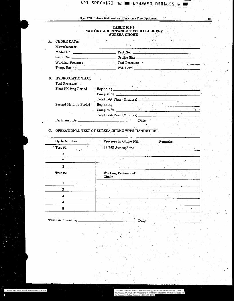
Test Performed By Date
COPYRIGHT 2003; American Petroleum Institute
Document provided by IHS Licensee=Kellogg Borwn & Root/3262700001, User=, 09/10/2003 07:10:01 MDT Questions or comments about this message: please callthe Document Policy Group at 1-800-451-1584.
--`,,,``,```,`,`,``,`,,``,`,,`-`-`,,`,,`,`,,`---
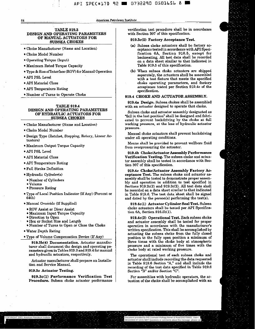
A P I S P E C * l 7 D 92 0732290 0501656 B
64 American.Petroleum Institute
TABLE 919.3 DESIGN AND OPERATING PARAMETERS
OF MANUAL ACTUATORS FOR SUBSEA CHOKES
Choke Manufacturer (Name and Location) Choke Model Number Operating Torque (Input) Maximum Rated Torque Capacity Type & Size of Interface (ROW for Manual Operation API PSL Level API Material Class API Temperature Rating Number of Turns to Operate Choke
TABLE 919.4 DESIGN AND OPERATING PARAMETERS
OF HYDRAULIC ACTUATORS FOR SUBSEA CHOKES
Choke Manufacturer (Name and Location) Choke Model Number Design Type (Ratchet, Stepping, Rotary, Linear Ac-
Maximum Output Torque Capacity API PSL Level API Material Class API Temperature Rating Full Stroke Definition Hydraulic Cylindeds)
tuators)
Number of Cylinders Volume Pressure Rating
64th) Type of Local Position Indicator (If Any) (Percent or
Manual Override (If Supplied) ROV Assist or Diver Assist Maximum Input Torque Capacity Direction to Open Hex or Socket Size and Length Number of Turns to Open or Close the Choke
Water Depth Rating Type of Volume Compensation Device (If Any)
919.3b(4) Documentation. Actuator manufac- turer shall document the design and operating pa- rameters givenin Tables 919.3 and 919.4 for manual and hydraulic actuators, respectively.
Actuator manufacturer shall prepare an Installa- tion and Service Manual. 919.3~ Actuator Testing.
919.3c(1) Performance Verification Test Procedure. Subsea choke actuator performance
verification test procedure shall be in accordance with Section 307 of this specification.
919.3c(2) Factory Acceptance Test. (a) Subsea choke actuators shall be factory ac-
ceptance tested in accordance with API Speci- fication 6A, Section 916.6, except for backseating. All test data shall be recorded on a data sheet similar to that indicated in Table 919.6 of this specification.
(b) When subsea choke actuators are shipped separately, the actuators shall be assembled with a test fixture that meets the specified choke operating parameters, and factory acceptance teisted per Section 919.4~ of the specification.
919.4 CHOKE AND ACTUATOR ASSEMBLY. 919.4a Design. Subsea chokes shall be assembled
with an actuator designed to operate that choke. Subsea choke and actuator assembly designated as
“fail in the last position” shall be designed and fabri- cated to prevent backdriving by the choke at full working pressure, at the loss of hydraulic actuator pressure.
Manual choke actuators shall prevent backdriving under all operating conditions.
Means shall be provided to prevent wellbore fluid from overpressuring the actuator.
919.413 ChokdActuator Assembly Performance Verification Testing. The subsea choke and actua- tor assembly shall be tested in accordance with Sec- tion 307 of this specification.
919.4~ Choke/Actuator Assembly Factory Ac- ceptance Test. The subsea choke and actuator as- sembly shall be tested to demonstrate proper assem- bly and operation in addition to test specified in Sections 919.2c(2) and 919.3c(2). All test data shall be recorded on a data sheet similar to that indicated in Table 919.6. The test data sheet shall be signed and dated by the person(s) performing the test(s).
919.4c(l) Actuator Cylinder Seal Test. Subsea choke actuators shall be tested per API Specifica- tion 6A, Section 916.5b(1).
919.4c(2) Operational Test. Each subsea choke and actuator assembly shall be tested for proper operation in accordance with the manufacturer‘s written specification. This shall be accomplished by actuating the subsea choke from the fully closed position to the fully open position a minimum of three times with the choke body at atmospheric pressure and a minimum of five times with the choke body at rated working pressure.
The operational test of each subsea choke and actuator shall include recording the data requested in Table 919.6 Section “A,” and shall include the recording of the test data specified in Table 919.6 Section “B” andor Section “C”.
For assemblies with hydraulic operators, the ac- tuation of the choke shall be accomplished with an
COPYRIGHT 2003; American Petroleum Institute
Document provided by IHS Licensee=Kellogg Borwn & Root/3262700001, User=, 09/10/2003 07:10:01 MDT Questions or comments about this message: please callthe Document Policy Group at 1-800-451-1584.
--`,,,``,```,`,`,``,`,,``,`,,`-`-`,,`,,`,`,,`---
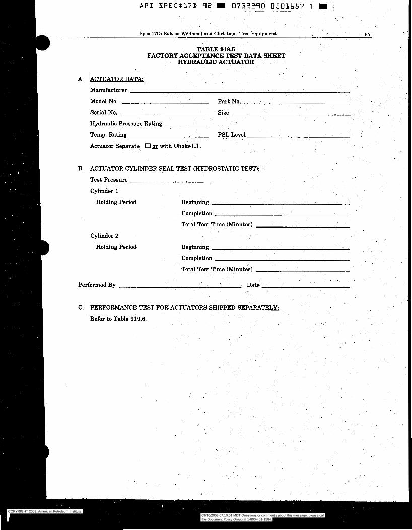
A P I SPEC*17D 7 2 W 0732270 O501657 T 9 ' ~. " ~ .~ ~ ~ ~~
. -
Spec 17D: Subeea Wellhead and Christmas Tree Equipment 66
TABLE 919.5 FACTORY ACCEPTANCE TEST DATA SHEET
HyDRGuLIC ACTUATOR
A. -TORD=
Manufacturer
Model No. Part~No.
Serial No.
Hydraulic Pressure Rating
Temp. Rating PSL Level
Actuator Separate O m with Choke O
. .-
Size
B. &J'UATOR C W E R SE& TEST (HYDROSTATIC TEST):
Test Pressure
Cylinder 1
Holding Period Beginning
Cylinder 2
Holding Period
Completion
Total Test Time (Minutes)
Beginning
Completion
Total Test Time (Minutes)
.~
Performed By ~ ~ Date
COPYRIGHT 2003; American Petroleum Institute
Document provided by IHS Licensee=Kellogg Borwn & Root/3262700001, User=, 09/10/2003 07:10:01 MDT Questions or comments about this message: please callthe Document Policy Group at 1-800-451-1584.
--`,,,``,```,`,`,``,`,,``,`,,`-`-`,,`,,`,`,,`---
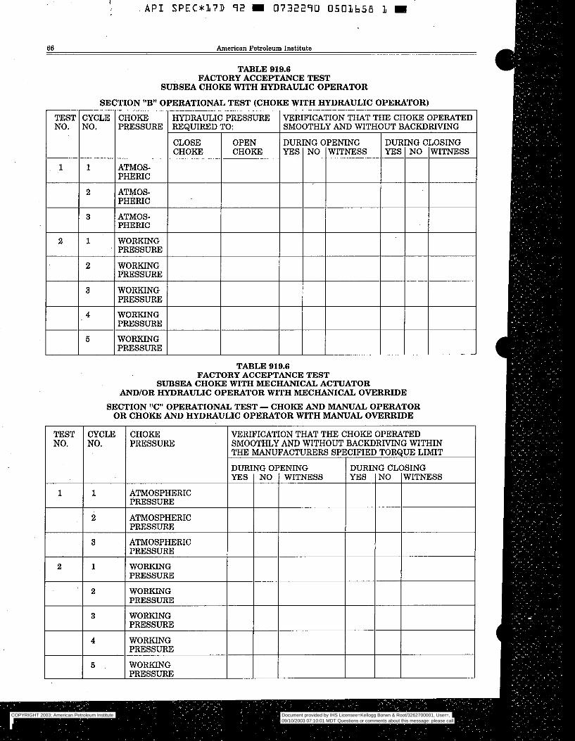
l - A P I S P E C * l 7 D 92 m 0732290 0501b58 L I
66 American Petroleum Institute
TABLE 919.6 FACTORYACCEPTANCETEST
SUBSEA CHOKE WITH HYDRAULIC OPERATOR
SECTION "B" OPERATIONAL TEST (CHOKE WITH HYDRAULIC OPERATOR)
TEST NO.
CYCLE NO.
CHOKE PRESSURE
VERIFICATION THAT THE CHOKE OPERATED SMOOTHLY AND WITHOUT BACKDRIVING
I
HYDRAULIC PRESSURE REQUIRED TO:
CHOKE CHOKE DUR YES
TG CLOSING
1 ATMOS- PHERIC
ATMOS- PHERIC
1
2
3 ATMOS- PHERIC I 1 WORKING PRESSURE
2
2 WORKING PRESSURE I
3 WORKING PRESSURE
4 WORKING PRESSURE
5 WORKING PRESSURE
TABLE 919.6 FACTORY ACCEPTANCE TEST
SUBSEA CHOKE WITH MECHANICAL ACTUATOR AND/OR HYDRAULIC OPERATOR WITH MECHANICAL OVERRIDE
SECTION "C" OPERATIONAL TEST - CHOKE AND MANUAL OPERATOR OR CHOKE AND HYDRAULIC OPERATOR WITH MANUAL OVERRIDE
TEST NO.
CYCLE NO.
CHOKE PRESSURE
VERIFICATION THAT THE CHOKE OPERATED SMOOTHLY AND WITHOUT BACKDRIVING WITHIN THE MANUFACTURERS SPECIFIED TORQUE LIMIT
DURING OPENING DURING CLOSING YES NO WITNESS YES NO WITNESS
1 1 ATMOSPHERIC PRESSURE
2 ATMOSPHERIC PRESSURE
3 ATMOSPHERIC PRESSURE
WORKING PRESSURE
WORKING PRESSURE
2 1
2
3 WORKING PRESSURE
4 WORKING PRESSURE
5 WORKING PRESSURE
COPYRIGHT 2003; American Petroleum Institute
Document provided by IHS Licensee=Kellogg Borwn & Root/3262700001, User=, 09/10/2003 07:10:01 MDT Questions or comments about this message: please callthe Document Policy Group at 1-800-451-1584.
--`,,,``,```,`,`,``,`,,``,`,,`-`-`,,`,,`,`,,`---
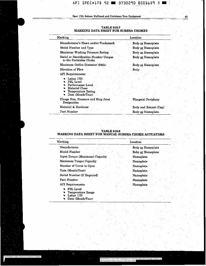
A P I S P E C * 1 7 D 92 m 0732270 0501659 3 m .
~ ~~~
~ ~ ~ _ ~ _
B Spec 17D: Subsea Wellhead and Christmas Tree Equipment 67
~ . TABLE 919.7 MARKING DATA SHEET FOR SUBESA CHOKES
Marking Location
Manufacturer's Name and/orTrademark Model Number and Type Maximum Working Pressure Rating Serial or Identification Number Unique
Maximum Orifice Diameter (64th) Direction of Flow
to the Particular Choke
AF'I Requirements: Letter 17D PSL Level Performance Level Material-Class Temperature Rating Date (MonthNear)
Designation Flange Size, Pressure and Ring Joint
Body PE Nameplate Body-@ Nameplate Body py Nameplate Body PL: Nameplate
Body p~ Nameplate Body
Flange(s) Periphery
Material & Hardness Body and Bonnet (Cap) Part Number Body PE Nameplate
TABLE 919.8 MARKING DATA SHEET FOR MANUAL SUBSEA CHOKE-ACTUATORS
Marking Location
Manufacturer Body p~ Nameplate Model Number . - Boby p~ Nameplate Input Torque (Maximum) Capacity Nameplate Maximum Torque Capacity Nameplate Number of Turns to Open Nameplate Date (MonthNear) Nameplate Serial Number (If Required) Nameplate Part Number Nameplate . .
A P T Requirements Nameplate PSL Level Temperature Range Letter 17D Date (MonthNear)
COPYRIGHT 2003; American Petroleum Institute
Document provided by IHS Licensee=Kellogg Borwn & Root/3262700001, User=, 09/10/2003 07:10:01 MDT Questions or comments about this message: please callthe Document Policy Group at 1-800-451-1584.
--`,,,``,```,`,`,``,`,,``,`,,`-`-`,,`,,`,`,,`---
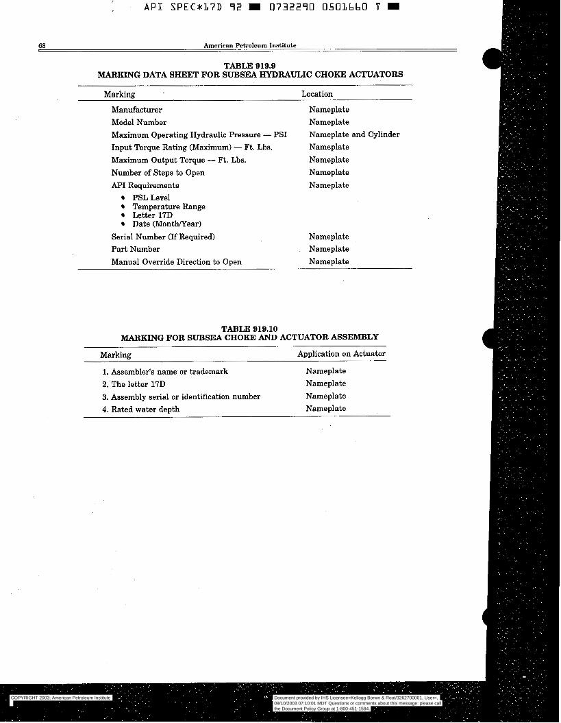
MARKING DATA SKEET FOR SUBSEA HYDRAULIC C H O m ACTUATORS
Markine Location
Manufacturer Model Number Maximum Operating Hydraulic Pressure - PSI Input Torque Rating (Maximum) - Ft. Lbs. Maximum Output Torque - R. Lbs. Number of Steps to Open API Requirements
PSL Level Temperature Range Letter 17D Date (MontWear)
Serial Number (If Required) Part Number Manual Override Direction to Open
Nameplate Nameplate Nameplate and Cylinder Nameplate Nameplate Nameplate Nameplate
Nameplate Nameplate Nameplate
TABLE 919.10 MARKING FOR SUBSEA CHOKE AND ACTUATOR ASSEMBLY
Marking Application on Actuator
1. Assembler's name or trademark Nameplate 2, The letter 17D Nameplate 3. Assembly serial or identification number Nameplate 4. Rated water depth Nameplate
COPYRIGHT 2003; American Petroleum Institute
Document provided by IHS Licensee=Kellogg Borwn & Root/3262700001, User=, 09/10/2003 07:10:01 MDT Questions or comments about this message: please callthe Document Policy Group at 1-800-451-1584.
--`,,,``,```,`,`,``,`,,``,`,,`-`-`,,`,,`,`,,`---
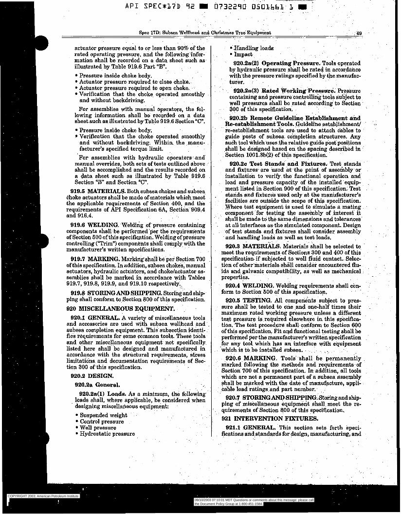
~ -
Spec 17D: Snbaea Wellhead and Christmas Tres Equipment .. ~ - 6 9 ~.
actuator pressure equal to or less than 90% of the rated operating pressure, and the following infor- mation shall be recorded on a data sheet such as illustrated by Table 919.6 Part “B”.
Pressure inside choke body. Actuator pressure required to close choke. Actuator pressure required to open choke. Verification that the choke operated smoothly and without backdriving. - For assemblies with manual operators, the fol-
lowing information shall be recorded. on a data sheet such asillustrated by Table 919.6 Sec€ion ”C”,
Pressure inside choke body. Verification that the choke operated smoothly and without backdriving; Within the manu- facturer’s specified torque limit. For- assemblies with hydraulic operators and
manual overrides, both sets of testa outlined above- shall be accomplished and the resulta recorded on a data sheet such as illustrated by Table 919.6 Section “B” and Section “C”.
919.5 MATERIALS. Both subsea chokes and subsea choke actuators shall be made of-materials which meet the applicable requirements of Section 400, and the requirements of API Specification 6A, Section.1909.4 and 916.4.
919.6 WELDING. .Welding of pressure containing components shall-be performed-per the requirements of Section 500 of this specification. Welding of pressure controlling (“Trim”) compone-nts shall comply with the manufacturer’s written specifications.
919.7 MARKING. Markingshallbe per Section 700 of this specification. In addition, subsea chokés, manual actuators, hydraulic actuators, and choke/actuator as- semblies shall be marked in accordance with Tables 919.7, 919.8, 919.9, and 919.10 respectively.
919.8 STORING AND SHIPPING. Storing A d ship- ping shall conform to Section 800 of this specification. 920 MISCELLANEOUS EQWMENT.
920.1 GENERAL. A variety of miscellaneous tools and accessories are used with subsea wellhead and subsea completion equipment. This subsection identi- fies requirements for some common tools. These tools and other miscellaneous equipment not specifically listed here shall be designed and manufactured in accordance with the structural requirements, stress limitatiöns. and documentation requirements of Sec- tion 300 of this specification.
920.2 DESIGN. 920.2~1 General.
920.2a(l) Loads. As a minim-, the following loads shall, where applicable, be. considered when designing miscellañeous equipment:
Suspended weight Control pressure Well pressure Hydrostatic pressure
COPYRIGHT 2003; American Petroleum Institute
Document provided by IHS Licensee=Kellogg Borwn & Root/3262700001, User=, 09/10/2003 07:10:01 MDT Questions or comments about this message: please callthe Document Policy Group at 1-800-451-1584.
--`,,,``,```,`,`,``,`,,``,`,,`-`-`,,`,,`,`,,`---

A P I SPEC*37D 72 m 0732270 0503662 3 m
70 American Petroleum Institute
testing of intervention fixtures fitted to subsea well equipment to facilitate support by divers, remotely operated vehicles, and atmospheric diving systems. Intervention tools and intervention systems are not covered by this specification.
Candidate configurations for potential standardiza- tion of generic types of intervention fixtures are given in Appendix C of this specification.
921.2 DESIGN.
ments. 921.2a General Performance/Service Require-
921.2a(l) Design Requirements. Intervention fi tures shall be designed in accordance with Sec- tion 300 of this specification, considering all loads specified in this section.
Maximum allowable column buckling load shall not exceed 1/2 critical buckling load..
921.2a(2) Alignment Requirements. Where ap- plicable, intervention fixtures shall be designed for engagement by a mating intervention tool at an initial axial misalignment angle of at least 5 de- grees without binding or damage.
921.2a(3) Fixture Functions. Intervention fix- tures may be designed for a single function (i.e., grasping) or for multiple functions (i.e., docking and rotary actuation).
921.2a(4) Accessibility. Intervention fixtures should be fitted to subsea well equipment' in a manner that does not interfere with other inter- vention equipment or subsea well functions.
921.2a(S) Fixture IdentificationlMarkings. In- tervention fNtures shall be clearly marked by use of painted, cutout or embossed characters (i.e., let- ters, numbers, or symbols). . Painted characters should be considered tem- porary and should not be used for applications re- quiring readability longer than three months.
Permanent markings shall be presented in one or more of the following options: - Characters cut out of a U4-inch (6 mm) or thicker
plate or base. - Characters having at least V4-inch (6 mm) thick-
ness embossed on a plate or base. - Characters incorporated into a plaque or tablet
specially designed for long life, subsea visual marking per the manufacturer's written speci- fication.
Where practicable, minimum character size should be 4-inch (100 m m ) high with a U2-inch (12 mm) minimum line width.
Plates or -bases for. cutout and embossed charac- ters should be painted a nonreflective light color. Embossed characters should be painted a nonreflec- tive black.
921,2a(6) Candidate API Standard Interven- tion Fixtures, Candidate intervention fixtures are included in Appendix C of this specification.
Design details of candidate AF'I Standard inter- vention fixtures are included in Appendix C of this specification.
Intervention fmtures other than those defined in Appendix C may be utilized as long as they are designed, manufactured and tested in accordance with the requirements set forth in this specification. 921.2b Grasping Intervention Fixtures.
921.2b(l) Description. Grasping intervention fixtures are fitted to subsea well equipment to pro- vide a standard interface for an Intervention Sys- tem. Grasping may be by a diver's hand or a ma- nipulator arm having a parallel or pincer jaw.
921.2b(2) Performance/Service Require- mente. Grasping. intervention fixtures shall be designed to withstand a minimum of:
A force of 500 pounds (2200 Newtons) applied
A gripping force of 500 pounds (2200 Newtons). 921.2~ Docking Intervention Fixtures.
921,2c(l) Description. Docking intervention fix- tures are fitted to subsea equipment to allow an intervention system to attach itself in a defined position.
921.2c(2) Performance/Service Require- ments. Docking intervention fixtures (when fully engaged) shall be designed to withstand the larger stresses resulting from either a force of 500 pounds (2200 Newtons) applied in any direction, or a 3000 fi-lbs (4050 N-m) moment applied in any direction.
Docking intervention fixtures should have no moving parts and should be designed to preclude trapping the Intervention System. 921.2d Landing Intervention Fixtures.
921.2d( 1) Description. Landing intervention fix- tures are designated support platforms or work space to allow an Intervention System to sit, stand, or otherwise position itself on a flat horizontal surface to carry out Intervention Tasks.
921.2d(2) Performance/Service Require- ments. Minimum landing intervention fmture size, load, and clearance requirements shall be as de- fined on Table 921.1. Additional clearance should be provided for sled, work packages, or other ap- purtenances carried by the intervention system. There should be clear access to the landing fixture and there should be no overhang which interferes with vertical access.
The landing intervention fixture shall be designed to support the weight of the defined intervention system in air during dry systems tests and to sup- port tool reaction forces. -. Landing-intervention fixtürès should be of open grid construction to minimize buildup of debris and should have no obstructions which could interfere with landing a flat-bottomed intervention system. Large landing intervention fixtures may require hinges or other special features to facilitate rig handling and installatiodretrieval operations.
from any direction.
COPYRIGHT 2003; American Petroleum Institute
Document provided by IHS Licensee=Kellogg Borwn & Root/3262700001, User=, 09/10/2003 07:10:01 MDT Questions or comments about this message: please callthe Document Policy Group at 1-800-451-1584.
--`,,,``,```,`,`,``,`,,``,`,,`-`-`,,`,,`,`,,`---

I
COPYRIGHT 2003; American Petroleum Institute
Document provided by IHS Licensee=Kellogg Borwn & Root/3262700001, User=, 09/10/2003 07:10:01 MDT Questions or comments about this message: please callthe Document Policy Group at 1-800-451-1584.
--`,,,``,```,`,`,``,`,,``,`,,`-`-`,,`,,`,`,,`---

~
A P I SPEC*37D 92 m 0732290 0503664 7 m
72 American Petroleum Institute
921,2e(3) Design Details. Design details of Can- didate API Standard Linear Actuator Intervention Fixtures are included in Appendix C of this specifi- cation. 921.2f Rotary Actuator Intervention Fixtures.
921.2f(1) Description. Rotary Actuator Inter- vention Fixtures shall be designed to provide a means for a Rotary Actuator Intervention Tool to apply torque to a rod or other linkage to operate a valve, connecting device, or other rotationally op- erated subsea well equipment apparatus.
921.2f(2) PerfoormancelService Require- ments, Rotary Actuator Intervention Fixtures and associated structure shall be designed in accord- ance with Section 921.2a(1) of this specification to transmit and resist torque for selected torque clas- sifications in accordance with Table 921.3 of this specification.
TABLE 921.3 ROTARY ACTUATOR INTERVENTION
FIXTURE CLASSIFICATION
CLASSIFICATION MAXIMUM DESIGN WORKING TORQUE
(FT-LB) (N")
-1 50 (70) 2 200 (270) 3 1,000 (1350) 4 2,000 (2700) 5 5,000 (6750)
7 25,000 (33750) 6 10,000 (13500)
921.2g Fluid Coupling Intervention Fixtures. 921.2g(1) Description. Fluid coupling interven-
tion fixtures are fitted onto subsea equipment to facilitate access to fluid piping circuits.
921.2g(2) Performance/Service Require- ments. Fluid coupling intervention fixtures shall not have seals. All seal elements shall be part of the intervention tool.
Corrosion resistant materials shall be used for fluid coupling seal bores,
A removable fluid coupling intervention fixture protector should be provided to protect seal sur- faces from damage, debris, or marine growth. If the protector is used to contain pressure, design of the protector shall be in accordance with Section 921.2a of this specification.
921.3 MATERIALS. Material selection for Inter- vention Fixtures shall be in accordance with Sections 400 and 921.2g(2) of this specification.
921.4 WELDING. Welding requirements for inter- vention fixtures to be in accordance with Section 500 of this specification,
921.6 TESTING. Design verification testing shall comply with Section 307 of this specification.
Factory acceptance testing shall comply with Sec- tion 600 of this specification. In addition, all inter- vention fixtures shall be tested in accordance with manufacturer's written specification prior to deliv- ery to verify:
Functional performance Accessibility by the intervention system and in- tervention tool (may be verified by mockups, jigs, or fixtures). Pressure integrity of fluid coupling intervention fixtures by hydrostatic testing to a minimum of 1.5 times the working pressure for a minimum of 3 minutes.
921.6 MARKING. Marking shall be in accordance with Sections 700 and 921.2a(S) of this specification.
ping of intervention fixtures to be in accordance with Section 800 of this specification. 922 SUBSEA TREE ASSEMBLY. This section pro-
vides specification requirements for the assembly of equipment covered in Section 900 of this specification to configure the subsea tree.
NOTE: Subsea tree assembly configurations vary de- pending on wellhead type, service, well shut-in pressure, water depth, reservoir parameters and environmental factors. As such, the subsea tree configuration require- ments specified in this section may not be applicable or desirable for all applications.
922.1 DESIGN. This section covers the assembly of equipment to configure the subsea tree, including valve placements and valve types. A schematic for a typical dual bore subsea tree is illustrated in Figure 922.1, while Figure 922.2 illustrates a typical single bore tree used with a tubing spool. Figures in this section are for illustration purposes only and should not be construed as limitations to applications.
922.h General. Equipment used in the assembly of the subsea tree which is covered in Sections 901 through 921 of this specification shall meet the re- quirements of Sections 901 through 921.
Equipment used in the assembly of the subsea tree which is not covered in Sections 901 through 921 shall comply with manufacturer's written specifica- tions.
The PSL designation, pressure rating, temperature rating, and material class assigned to the subsea tree assembly shall be determined by the minimum rating of any single component normally exposed to wellbore fluid used in the assembly of the subsea tree.
922.1b Master Valves. Any valve in the vertical bore of the tree between the wellhead and the tree side outlet shall be defined as a master valve. A subsea tree shall have one or more master valves in the vertical production (injection) bore, at least one of which shall be a hydraulically operated fail-closed valve.
922.1~ Wing Valves. A wing valve is any valve in the subsea tree assembly that controls either the
921.7 STORING AND SHIPPING. Storing and ship-
COPYRIGHT 2003; American Petroleum Institute
Document provided by IHS Licensee=Kellogg Borwn & Root/3262700001, User=, 09/10/2003 07:10:01 MDT Questions or comments about this message: please callthe Document Policy Group at 1-800-451-1584.
--`,,,``,```,`,`,``,`,,``,`,,`-`-`,,`,,`,`,,`---
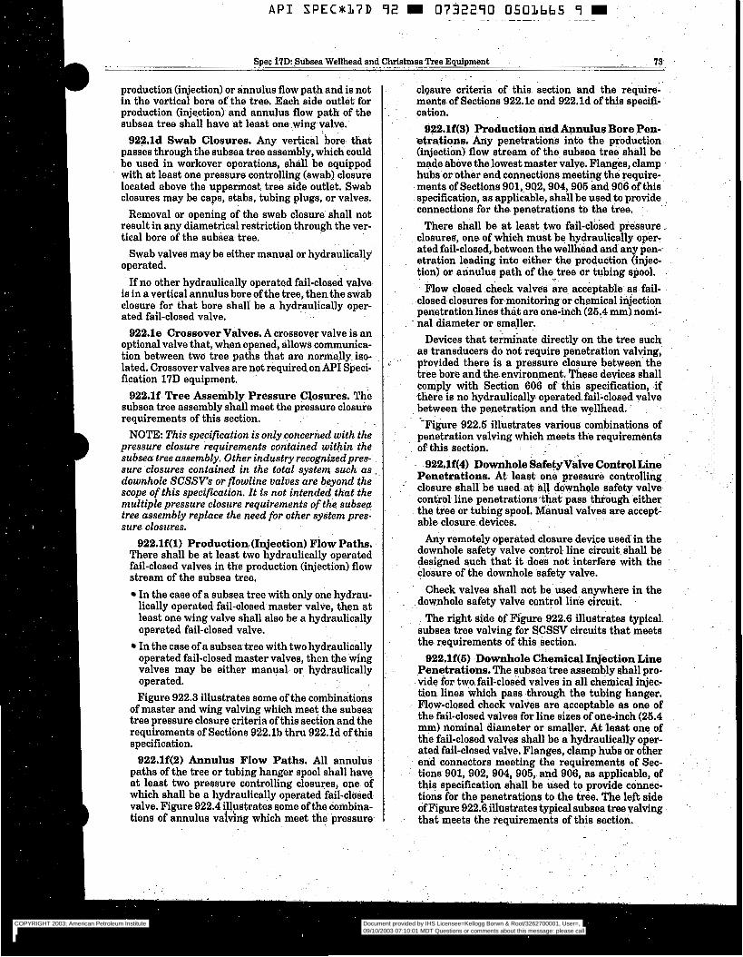
A P I SPEC*17D 92 m 0732290 0501665 9 m , ~. ~ ~. ~ ~ ~~ ~
Spec 17D: Subsea Wellhead and Christmas Tree Equipment 73
production (injection) or annulus flow path and is not in the vertical bore of the tree. Each side outlet- for production (injection) and annulus flow path of the subsea tree shall have at least one wing valve.
922.1d Swab Closures. Any vertical bore that passes through the subsea tree assembly, which could be used in workover operations, shall be equipped with at least one pressure controlling (swab) closure located above the upperinost tree side outlet, Swab closures may be caps, stabs, tubing plugs, or valves.
Removal or opening of the swab closure shall not result in any diametrical restriction through the ver- tical bore of the subsea tree.
Swab valves may be either manual or hydraulically operated.
If no other hydraulically operated fail-closed valve is in a vertical annulus bore of the tree, then the swab closure for that bore shall be a hydraulically oper- ated fail-closed valve.
922.18 Crossover Valves. A crossover valve is an optional valve that, when opened, allows communica- tion between two tree paths that are normally iso- lated. Crossover valves are not requiredonAPE Speci- fication 17D equipment.
922.1f Tree Assembly Pressure Closures. The subsea tree assembly shall meet the pressure closure requirements of this section.
NOTE: This specification is only concerned with the pressure closure requirements contained within the subsea tree assembly. Other industry recognizedpres- sure closures contained in the total system such as .. downhole SCSSVs or flowline valves are beyond the scope of this specification. It is not intended that the multiple pressure closure requirements of the subsep tree assembly replace the need for other system pres- sure closures.
922.1f(l) Production (Injection) Flow Paths, There shall be at least two hydraulically operated fail-closed valves in the production (injection) flow stream of the subsea tree.
In the case of a subsea tree with only one hydrau- lically operated fail-closed master valve, then at least one wing valve shall also be a hydraulically operated fail-closed valve. In the case of a subsea tree with two hydraulically operated fail-closed master valves, then the wing valves may be either manual or hydraulically operated. Figure 922.3 illustrates some of the combinations
of master and wing valving which meet the subsea- tree pressure closure criteria of this section and the requirements of Sections 922.1b thru 922.1d of this specification.
922.1f(2) Annulus Flow Paths. All annulus paths of the tree or tubing hanger spool shall have at least two pressure controlling closures, one of which shall be a hydraulically operated fail-closed valve. Figure 922.4 illustrates some of the combina- tions of annulus vaidrig which meet the pressure
closure criteria of this section and the require- ments of Sections 922.1~ and 922.1d of this specifi- cation.
922.lf(3) Production and Annulus Bore Pen- etrations. Any penetrations into the production (injection) flow stream of the subsea tree shall be made above the lowest master valve. Flanges, clamp hubs or other end connections meeting the require- ments of Sections 901,.902,904,905 and 906 of this specification, as applicable, shall be used to provide connections for the penetrations to the tree.
There shall be at least two fail-closed pressure .~
closures, one of which must be hydraulically oper- ated fail-closed, between the wellhead and any pen- . etration leading into either the production Qnjec- tion) or annulus path of the tree or tubing spool, ..
Flow closed check valves are acceptable as fail- closed closures for monitoring or chemical injection penetration lines th& are one-inch (26.4 mm) nomi- nal diameter or smaller.
Devices that terminate directly on the tree such as transducers do not require penetration valving, provided there is a pressure closure between the tree bore and the environment. These devices shall comply with Section 606 of this specification, if there is no hydraulically operated fail-closed valve between the penetration and the wsllhead. -Figure 922.6 illustrates various combinations of
penetration valving which meets the requiremènts of. this se-ction.
922.1f(4) Downhole SafetyValve ContmlLine Penetrations. At least one. pressure controlling closure shall be used at all downhole safety valve control line penetrations that pass though either the tree or tubing spool, Manual valves are accept: able closure.devices.
Any remotely operated closure device used in the downhole safety valve control line circuit shall be designed such that it does not interfere with the closure of the downhole safety valve.
Check valves shall not be used anywhere in the downhole safety valve control line circuit.
The right side of Figure 922.6 illustrates typical subsea tree valving for SCSSV circuits that meets the requirements of this section.
922.lf(S) Downhole Chemical Tqjection Line Penetrations. The subsea tree assembly ahall pro- vide for two fail-closed valves in all chemical injec- tion lines which pass through the tubing hanger. Flow-closed check valves are acceptable as one of the fail-closed valves for line sizes of one-inch (26.4 mm) nominal diameter or smaller, At least one of the fail-closed valves shall be a hydraulically oper- ated fail-closed valve. Flanges, clamp hubs or other end connectors meeting the requirements of Sec- tions 901, 902, 904, 905, and-906, as applicable, of this specification shall be used to provide connec- tions for the penetrations to the tree, The left side of Figure 922.6 illustrates typical subsea tree valving that meets the requirements of this section.
..
COPYRIGHT 2003; American Petroleum Institute
Document provided by IHS Licensee=Kellogg Borwn & Root/3262700001, User=, 09/10/2003 07:10:01 MDT Questions or comments about this message: please callthe Document Policy Group at 1-800-451-1584.
--`,,,``,```,`,`,``,`,,``,`,,`-`-`,,`,,`,`,,`---
A P I S P E C x 1 7 D 92 m 0732290 050Lbbb O m
I4 American Petroleum Institute
922.2 MATERIALS. Materials used in the assem- bly of subsea trees shall conform to Section 400 of this specification.
922;3 WELDING. Welding during the assembly of subsea trees shall conform to Section 500 of this speci- fication.
922.4 TESTING. This section covers testing of subsea tree assemblies.
922.4a Performance Verification Testing. There are no performance verification testing requirements for subsea tree assemblies. However, all parts and equipment covered in Section 900 of this specifica- tion used in the assembly of subsea trees shall con- farm to its applicable performance verification test- ing requirements.
922.4b Factory Acceptance Testing. The subsea tree assembly shall be tested in accordance with API Specification 6A, Section 606.9. For TFL applica- tions, the subsea tree assembly shall be drift tested in accordance with M I Recommended Practice 17C, Sections 3.3b, 3.4a, 4.3a, 4.5a, and 4.8a.
The subsea tree assembly shall be factory accept- ance tested per the manufacturer’s written specifica- tion using actual mating equipment or an appropri-
ate test fixture that simulates the applicable guidebase, wellhead and tubing hanger interfaces.
NOTE: Integration testing oftotal system is beyond the scope of this specification. 922.5 I\IARKDNG. Marking for assembled subsea
trees shall conform with Section 700 of this specifica- tion. The subsea tree assembly shall be tagged with a nameplate labeled as “Subsea Tree Assembly”, located on the master valve or tree valve block, and contain the following information as a minimum:
Name and Location of AssemblerDate PSL Designation of Assembly Rate Working Pressure of Assembly Temperature Rating of Assembly Material Class of Assembly Drift TestDate 17D 922.6 STORING AND SHIPPING. The subsea tree
assembly shall be stored and shipped in accordance with Section 800 of this specification. No part or equip- ment on the assembled subsea tree shall be removed or replaced during storage or shipping unless the tree is successfully retested and then re-tagged.
COPYRIGHT 2003; American Petroleum Institute
Document provided by IHS Licensee=Kellogg Borwn & Root/3262700001, User=, 09/10/2003 07:10:01 MDT Questions or comments about this message: please callthe Document Policy Group at 1-800-451-1584.
--`,,,``,```,`,`,``,`,,``,`,,`-`-`,,`,,`,`,,`---
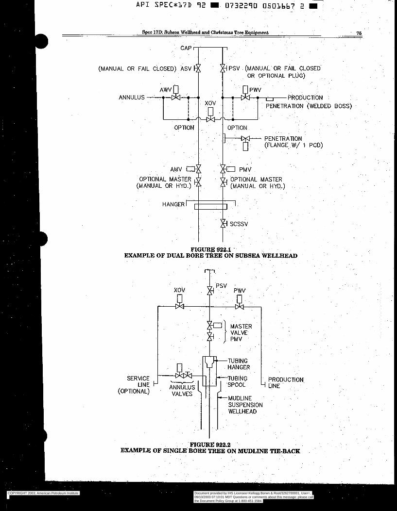
Spec 17D Subsea Wellhead and Christmas *=Equipment 76
(MANUAL OR FAIL CLOSED) ASV
ANNULUS ETRATlON (WELDED BOSS)
PENETRATION
OPTIONAL MASTER OPTIONAL MASTER (MANUAL OR HYD.) (MANUAL OR HYD.)
I I
I I - FIGURE 922.1
EXAMPLE OF DUAL BORE TREE ON SUBSEA WELLHEAD
SERVICE . LINE
(OPTIONAL)
PRODUCTION 4 LINE
FIGURË 922.2 . EXAMPLE OF SINGLE BORE TREE ON MUDLINE TIE-BACK
COPYRIGHT 2003; American Petroleum Institute
Document provided by IHS Licensee=Kellogg Borwn & Root/3262700001, User=, 09/10/2003 07:10:01 MDT Questions or comments about this message: please callthe Document Policy Group at 1-800-451-1584.
--`,,,``,```,`,`,``,`,,``,`,,`-`-`,,`,,`,`,,`---
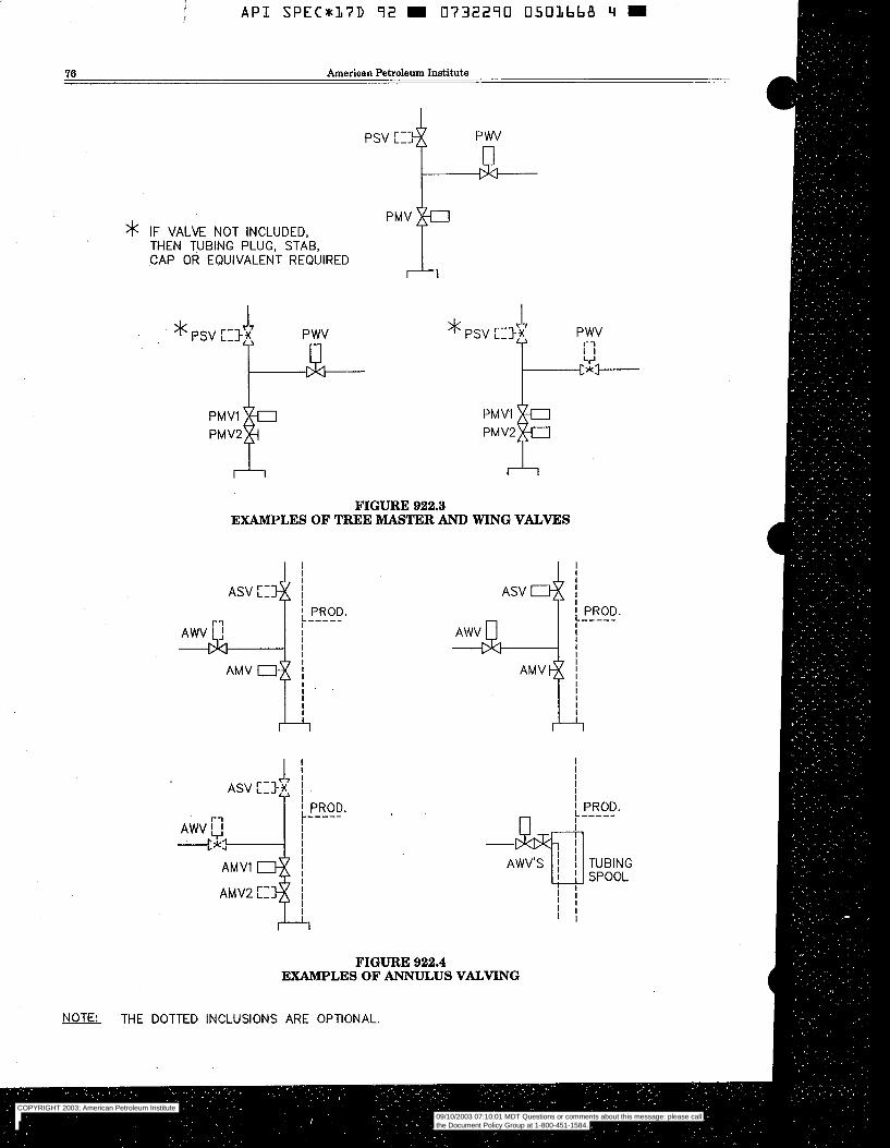
I A P I S P E C * 1 7 D 92 I 0732290 0501bbA 4 I
76 American Petroleum Institute
>k IF VALVE NOT INCLUDED, THEN TUBING PLUG, STAB, CAP OR EQUIVALENT REQUIRED
P wv
PMV
FIGURE 922.3 EXAMPLES OF TREE MASTER AND WING VALVES
AS" c# I l
I
I I""" PROD
I
I
l +
i ! PROD.
FIGURE 922.4 EXAMPLES OF ANNULUS VALVING
NOTE: THE DOTTED INCLUSIONS ARE OPTIONAL.
COPYRIGHT 2003; American Petroleum Institute
Document provided by IHS Licensee=Kellogg Borwn & Root/3262700001, User=, 09/10/2003 07:10:01 MDT Questions or comments about this message: please callthe Document Policy Group at 1-800-451-1584.
--`,,,``,```,`,`,``,`,,``,`,,`-`-`,,`,,`,`,,`---
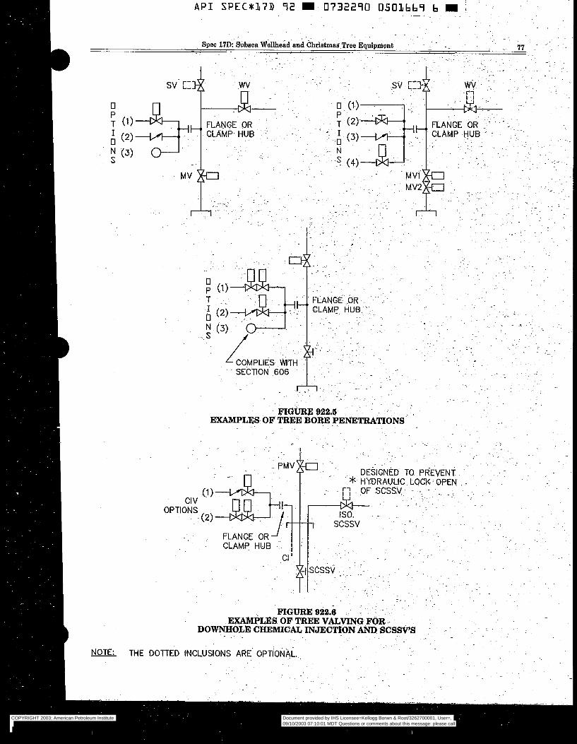
NOTE: TH E
COPYRIGHT 2003; American Petroleum Institute
Document provided by IHS Licensee=Kellogg Borwn & Root/3262700001, User=, 09/10/2003 07:10:01 MDT Questions or comments about this message: please callthe Document Policy Group at 1-800-451-1584.
--`,,,``,```,`,`,``,`,,``,`,,`-`-`,,`,,`,`,,`---
A P I SPEC*37D 9 2 9 0732290 0503670 2 E
78 American Petroleum Institute
SECTION 1000
SPECIFIC REQUIREMENTS SUBSEA WELLHEAD AND TUBING HANGER EQUIPMENT -
1001 SUBSEA WELLHEAD EQUIPMENT. 1001.1 GENERAL. This section describes Subsea
Wellhead Systems which are normally run from float- ing drilling rigs. It establishes standards and specifica- tions for this equipment. Guidelineless Systems are not addressed in this specification. The Subsea Well- head System supports and seals casing strings. It also supports the blow-out preventer stack (BOP) during drilling, and the subsea tree and possibly the tubing hanger after completion. The Subsea Wellhead System is installed at or near the mudline.
All pressure containing and pressure controlling parts included as part of the subsea wellhead equipment shall be designed to meet all of the requirements of the NACE Standard MR-01-75 “Sulfide Stress Cracking Resistant Metallic Materials for Oilfield Equipment.” These parts include:
Wellhead Housing 9 Casing Hanger Bodies
Annulus Seal Assemblies
NACE requirements: Lock Rings Load Rings Load Shoulders 16’ (406 mm) Suspension Equipment Bore Protectors and Wear Bushings
The following parts or features are excluded from the
1001.2 TEMPORARY GUIDE BASE (TGB). 1001.2a General. The temporary guide base (TGB)
provides a guide template for drilling the conductor hole, and stabbing the conductor pipe. It compen- sates for misalignment from irregular ocean bottom conditions, and provides a support base for the per- manent guide base. For guideline systems, it also establishes the initial anchor point for the guide- lines.
1001.2b Design. The design of TGB’s shall comply with Section 300 of this specification:
1001.2b(l) Loads. The following loads shall be considered and documented by the manufacturer when designing the TGB:
Ballast Guideline Tension Weight of Conductor Pipe Weight of Permanent Guide Base Assembly Soil Reaction The TGB shall be capable of supporting, as a
minimum, a static load of 175,000 pounds (780000 Newtons) on the interface with the permanent guidebase while the TGB is supported at four loca- tions, equally spaced 90 * 2 degrees apart and a minimum of 62 inches (1575 mm) from the center (radial measure).
1001.2b(2) Dimensions. (a) The TGB minimum bearing area shall be
75 square feet (7 square meters). This area may be augmented with weld-on or bolt-on extensions to compensate for soil strengths and anticipated loads.
(b) TGB should pass through a 15 foot (5 meter) square opening or as specified by the manufac- turer.
(c) TGB shall provide four guideline anchor points in position to match the guideposts on the PGB.
(d) Together with the permanent guide base, the TGB shall allow a minimum angular misalign- ment of 5 degrees between the conductor pipe and the temporary guide base.
(e) TGB shall provide a minimum storage volume of 75 cubic feet (2 cubic meters) for ballast material.
1001.2~ Materials. 1001.2c(l) The TGB shall be fabricated from
structural steel shapes and plates which conform to Section 400 of this specification.
1001.2c(2) Coatings shall conform to Section 304.7 of this specification.
1001.2d Testing. Performance verification test- ing shall conform to Section 307.5 of this specifica- tion. No factory acceptance testing is required. 1001.3 PERMANENT GUIDE BASE (PGB).
1001.3a General. The permanent guide base (PGB) provides entry into the well prior to BOP installation and, along with the four guideposts, gives guidance for running the subsea BOP stack or the subsea tree. It establishes structural support and final alignment for the wellhead system, and provides a seat and lock down for the conductor housing. PGB’s can be built as a single piece or split into two pieces to ease handling and installation. Optionally, they may include provi- sions for retrieval and to react flowline loads.
1001.3b Design. The design of PGB’s shall comply with Section 300 of this specification.
1001.3b(l) Loads. The following loads shall be considered and documented by the manufacturer when designing the PGB (see Figure 1001.3):
Conductor Pipe Weight Conductor Housing Weight Jetting String Weight when supported on the
Guideline Tension (see Figure 1001.3) Flowline Pull-In, Connection, or Installation Loads
Spider Beams
(see Figure 1001.1)
COPYRIGHT 2003; American Petroleum Institute
Document provided by IHS Licensee=Kellogg Borwn & Root/3262700001, User=, 09/10/2003 07:10:01 MDT Questions or comments about this message: please callthe Document Policy Group at 1-800-451-1584.
--`,,,``,```,`,`,``,`,,``,`,,`-`-`,,`,,`,`,,`---

A P I SPEC*17D 92 0732290 0501671 4'- i ~ - " ~
~. Spec 17D: Subsea Wellhead and Christmas Tree Equipment ~ ~. ~
79
I RISER TENSION
THERMAL
/ \
FIGURE 1001.1
.
LOADS AND REACTIONS FOR A SUBSEA COMPLETION
GUIDE POST -y I
TYP. 4 -PLACES
0 5/0" 0 a0 0.500 lA@l*
.
I PLACES
i- SUBSEA WELLHEAD HOUSING
J
-" GUIDE BASE PERMANENT
W *REF. ANSI Y í4 5M
NOTES: 1. GUIDE POSTS. POS,ITIONAL TOLERANCES ARE DETERMINED
RELATIVE TO THE WELLHEAD HOUSING BORE (DATUM -A-) METHOD OF MEASUREMENT TO BE SPECIFIED BY THE MANU- FACTURER
2. CUMULATIVE TOLERANCES BETWEEN ALL INTERFACING COM- . - PONËNTSUUST BE LESS THAN OR EQUAL TO THE POSITIONAL
TOLERANCE SHOWN 3. DIMENSION @) TO BE 8 FT. (2500 mm) MINIMUM
COPYRIGHT 2003; American Petroleum Institute
Document provided by IHS Licensee=Kellogg Borwn & Root/3262700001, User=, 09/10/2003 07:10:01 MDT Questions or comments about this message: please callthe Document Policy Group at 1-800-451-1584.
--`,,,``,```,`,`,``,`,,``,`,,`-`-`,,`,,`,`,,`---
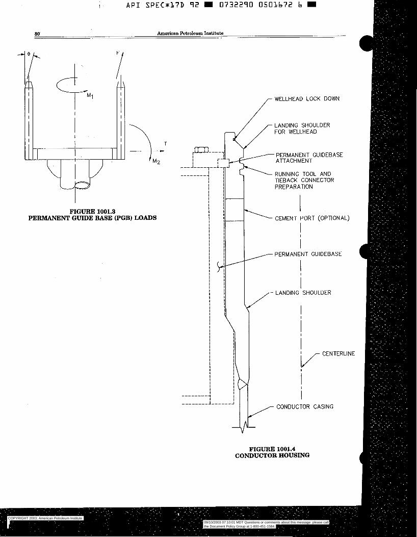
API S P E C 8 3 7 D 92 W 0732290 0503672 b E
80 American Petroleum Institute
I
I
1
FIGURE 1001.3 PERMANENT GUIDE BASE (PGB) LOADS
I
I
i ? I
I
I I
I
"" "
k
"
f WELLHEAD LOCK DOWN
/ LANDING SHOULDER FOR WELLHEAD
PERMANENT GUIDEBASE ATTACHMENT
RUNNING TOOL AND TIEBACK CONNECTOR PREPARATION
- 4 1 PERMANENT GUIDEBASE
V I LANDING SHOULDER
I I
FIGURE 1001.4 CONDUCTOR HOUSING
COPYRIGHT 2003; American Petroleum Institute
Document provided by IHS Licensee=Kellogg Borwn & Root/3262700001, User=, 09/10/2003 07:10:01 MDT Questions or comments about this message: please callthe Document Policy Group at 1-800-451-1584.
--`,,,``,```,`,`,``,`,,``,`,,`-`-`,,`,,`,`,,`---
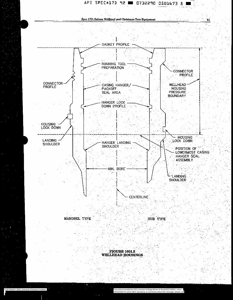
API SPEC*L7D 92 W 0732290 O503673 8 j ~ - 1
CONNECTOR PROFILE
- I I I I
RUNNING TOOL - PREPARATION
"
CONNECTÖR I 1
J HANGER LOCK i~
.. ~ ~ ~~
~.
S ---"- DOWN PROFILE
COPYRIGHT 2003; American Petroleum Institute
Document provided by IHS Licensee=Kellogg Borwn & Root/3262700001, User=, 09/10/2003 07:10:01 MDT Questions or comments about this message: please callthe Document Policy Group at 1-800-451-1584.
--`,,,``,```,`,`,``,`,,``,`,,`-`-`,,`,,`,`,,`---

I
A P I SPECn37D 92 m 0732290 O503674 T m
82 American Petroleum Institute
Environmental Reaction for TGB The PGB shall be capable of supporting, as a
minimum, a static load of 175,000 pounds (780000 Newtons) on the interface with the conductor hous- ing while the PGB is supported at four locations equally spaced 90 f 2 degrees apart and a miniumum of 62 inches (1575 mm) from the center (radial measure).
1001.3b(2) Dimensions. (a) The dimensions of the PGB shall conform to
(b) The guideposts shall be fabricated of 8 5/8" (219 the dimensions shown in Figure 1001.2.
mm) O.D. pipe or tubulars. (c) The length of the guidepost (dimension "H" of
Figure 1001.2) shall be 8 feet (2500 mm) mini- mum.
1001.3b(3) Functional Requirements. (a) When used with the temporary guide base, the
PGB shall allow a minimum angular misalign- ment of 5 degrees between a 30 inch nominal (762 mm) conductor pipe and the TGB. For other conductor pipe sizes, the manufacturer shall document the misalignment capability.
(b) Guideposts shall be field replaceable without welding.
(c) Guideposts can be either slotted or non-slotted. For slotted guideposts, provisions shall be made to insert guidelines of at least 3/4 inch (19 mm) 0.D. into the post with retainers at the top and at or near the bottom of the post.
(d) Provisions shall be made to attach guidelines to the top of the guideposts. These provisions shall be capable of being released and re-estab- lished.
1001.3~ Materials. 1001,3c(l) .The PGB shall be fabricated from
structural steel shapes and plates which conform to Section 400 of this specification.
1001,3c(2) Coatings shall conform to Section 304.7 of this specification. 1001.3d Testing. Performance verification test-
ing shall conform to Section 307.5 of this specifica- tion. No factory acceptance testing is required. 1001.4 CONDUCTOR HOUSING.
1001.4a General. The conductor housing attaches to the top of the conductor pipe to form the basic foundation of a subsea well. The housing typically has a means of attaching to the PGB which prevents rotation of the PGB with respect to the housing.
A typical conductor housing profile is shown in Figure 1001.4. The internal profile of the conductor housing includes a landing shoulder suitable for sup- porting the wellhead housing and the loads imposed during the drilling operation. Running tool prepara- tions should also be a part of the internal housing
profile. Cement return passageways may be incorpo- rated in the conductor housing/PGB assembly to al- low cement and mud returns to be directed below the PGB.
1001.4b Design. The design of the conductor hous- ing shall comply with Section 300 of this specifica- tion.
1001.4b(l) Loads. The following loads shall be considered and documented by the manufacturer when designing the conductor housing (refer to Section 1001.2b(l)):
Wellhead Loads Riser Forces PGB Loads (refer to Figures 1001.1 and 1001.3) Environmental Loads Pressure Loads Thermal Loads The interface between the conductor housing and
the PGB shall be designed for a rated load of at least 1.75,OOO pounds (780000 Newtons). The con- ductor housing shall have a minimum rated work- ing pressure of 1,000 psi (6,9 m a ) .
1001.4b(2) Dimensions. (a) The following dimensions shall apply to 30 inch
(762 mm) nominal Conductor Housings: Minimum I.D. 26.2 inch (665 mm) Maximum O.D. 37.38 inch (950 mm)
(b) The Conductor Housing is not limited to the 30" (762 mm) size. Rotary table dimensions should be considered when selecting the out- side diameter of the conductor housing. The drill bit gage diameter used for the next string of casing plus l/8 inch (3 mm) clearance should be considered when selecting the internal di- ameter of the conductor housing.
1001.4b(3) Bottom Connection. If the bottom end connection is to be welded, it shall be prepared for a full penetration butt-weld. 1001.4~ Materials.
ply with Section 400 of this specification. 1001.4c(l) The housing body material shall com-
1001.4c(2) Impact testing is not required. 1001.4d Testing. Performance verification test-
ing shall conform to Section 307.5 of this specifica- tion. No factory acceptance testing is required. 1001.6 WELLHEAD HOUSING.
1001.6a General. The wellhead housing lands in- side the conductor housing. It provides pressure in- tegrity for the well, suspends the surface and subse- quent casing strings and tubing hanger and reacts external loads. The BOP stack or subsea tree at- taches to the top of the wellhead housing using a compatible wellhead connector. The wellhead hous- ing shall accept tubing hangers or tubing hanger adapter. The standard system sizes are given in Table
COPYRIGHT 2003; American Petroleum Institute
Document provided by IHS Licensee=Kellogg Borwn & Root/3262700001, User=, 09/10/2003 07:10:01 MDT Questions or comments about this message: please callthe Document Policy Group at 1-800-451-1584.
--`,,,``,```,`,`,``,`,,``,`,,`-`-`,,`,,`,`,,`---
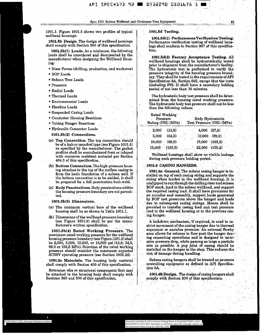
API SPEC*h7D 92 W 0732290 0 5 0 h b 7 5 h W i
Spec 17D: Subsea Wellhead and Christmas Tree Equipment . 03
1001.1. Figure 1001.5 shows two profiles of typical wellhead housings.
1001.6b Design. The design of wellheadhousings shall comply with Section 300 of this specification.
1001.6b(l) Loads. As a minimum, the following loads shall be considered and documented by the manufacturer when designing the Wellhead Hous- ing:
Riser Forces (drilling, production, and workover) BOP Loads Subsea Tree Loads Pressure Radial Loads Thermal Loads Environmental Loads Flowline Loads Suspended Casing Loads Conductor Housing Reactions Tubing Hanger Reactions Hydraulic Connector Loads 1001.6b(2) Connections.
(a) Top Connection. The top connection should be of a hub or mandrel type (see Figure 1001.5) as specified b$ the manufacturer. The gasket profiles shall be manufactured from or inlayed with corrosion resistant material per Section 404.3 of this specification. ~ .
(b) Bottom Connection. The high-pressure hous- ing attaches to the top of the surface casing to form the basic foundation of a subsea well. If the bottom connection is to be welded, it shall be prepared for a full penetration butt-weld.
(c) Body Penetrations. Body penetrations within the housing pressure boundary are not permit- ted.
1001.6b(3) Dimensions. - . (a) The minimum vertical bore of the wellhead
housing shall be as- shown in Table 1001.1. (b) Dimensions of the wellhead-pressure boundary
(see Figure 1001.5) shall- be- per the manu- facturer's written specification. - . . . . ~-
1001.6b(4) Rated Working ;Pressure. The maximum rated workingpressure for the wellhead housing pressure boundary (see Fígure-lQOl.5i) shall be 2,000, 5,000, 10,000, or 15,000 psi (13,8; 34,5;~ 69,O or 103,5 MPa). Selection of the rated working pressure should consider the maximum expected SCSSV operating pressure (see Section 1002.2d). 1001.6~ Materials. The housing body material
shall comply with Section 400 of this specification. Extension ribs or structural components tha t mai
be attached to the housing body shall comply with Sections 300 and 500 af this specification.
. -
1001.6d Testing.
1001.6d(l) PerformanceVerificationTestiig. Performance verification testing of wellhead hous- ings shall conform to Section 307 of this specifica- tion.
lOÓl.6d(2) Factory Acceptance ~Testing. All wellhead housings shall be hydrostatically tested prior to shipment from the manufacturer's facility. The hydrostatic test. is performed to verify the pressure integrity of the housing pressure bound- ary. They shall be.tested to €he requirements ofAPI Specification 6A, Section 605, except that the tests (including PSL 2) shall have a-secondary holding period of not less than 15 minutes.
The hydrostatic body test pressure shall be deter- mined from the housing rated working pressure. The hydrostatic body test pressure shall not be less than the following Values:
Rated Working ~
Pressure Body Hydrostatic Rating (PSI) (MPa) Test Pressure (PSI) (MPa)
~ ..
2,000 (is$) 4,000 (27,6) 5,000 (34,5) 10,000 ~ (69,O) lÖ,OOO .(69,0) 15,000 (103,5) 15,000 (103,5) - 22,500. (155,2)
~.
Wellhead housings shall show no visible leakage - .
during each pressure-holding period. . ~ ~
1001.6 CASING HANGERS. -~
1001.6a General. The subsea casinghanger is in- stalled on top of each casing string and.supports the . - string when landed ih the wellhead housing.- It is :
configured to run through the drilling riser and subsea BOP stack, land in the subsea wellhead, and support the required casing load. It shall have provisions for an annulus seal assembly, support loads generated .-
by BOP test pressures above the hanger and loads-: _due- to subsequent casing. strings. Means shall be provided to transfer casing load and .test -pressure load to the wellhead housing-or to the previous cas- ing hanger.
Ä Iockdöwn. mechanism; if reqüired,.is used to re- strict movement of the casing hanger due to thermal expansion or annulus pressure.-An external flowby area allows for re€urne to flow'past the hanger dur-, ing cemeñting operations and is designed to mini- mize presswe drop, while passing as large a particle size as possibh. A pup j6int of casing sh6uld.~ be installed onthe hanger in the shop, This-reduces the risk of damage- during handling.
~. . .
Subsea.casing hangers shall be treated as pressure controlling equipment as defined in API Specifica- tion 6A. ~ . -
lOOl.6b Desi&. The design of casing hangers. shsll komply mith Section 300 of this specification.
.~
COPYRIGHT 2003; American Petroleum Institute
Document provided by IHS Licensee=Kellogg Borwn & Root/3262700001, User=, 09/10/2003 07:10:01 MDT Questions or comments about this message: please callthe Document Policy Group at 1-800-451-1584.
--`,,,``,```,`,`,``,`,,``,`,,`-`-`,,`,,`,`,,`---

!T A P I S P E C * l 7 D 72 W 0732270 0 5 0 l b 7 b 3 E
84 American Petroleum Institute
NOMINAL SYSTEM DESIGNATION
(INCHES-PSI) (""Pa)
18-3/4-10M (476-69) 18-3/4-15M (476-103) 16-3/4-5M (425-35) 16-3/4-10M (425-69)
20-3/4-21-1/4-2M (527-540-14) 13-5/8-10M (346-69) 21-1/4-5M (540.35)
13-5/8-15M (346-103) 18-3/4-10M (476-69) 13-5/8-15M (346-103)
TABLE 1001.1 WELLHEAD SYSTEMS
STANDARD SIZES AND TYPES
BOP STACK HIGH PRESSURE CONFIGURATION HOUSING
WORKING PRESSURE (PSI) (MPa)
SINGLE 10,000 (69,O) SINGLE 15,000 (103,5) SINGLE 5.000 (34,5) SINGLE 10,000 (69,O) DUAL 2,000 (13,8) I 10.000 (69.0)
DUAL I 5,000 (34,5)
MINIMUM VERTICAL
BORE (INCHES) (mm)
17.56 (446) 17.56 (446) 15.12 (384) 15.12 (384) 18.59 (472) 12.31 (313) 18.59 (472)
15,000 (103,5) 12.31 (313) DUAL 10,000 (69,O) 17.56 (446)
15,000 (103,5) 12.31 (313)
1001.6b(l) Loads. As a minimum, the following loads shall be considered and documented by the manufacturer when designing casing hangers:
Suspended Weight Overpull Pressure, Internal and External Thermal Torsional Radial Impact 1001.-6b(2) Threaded Connections. The type
of casing threads on the hanger shall be per API Specification 6A, Section 902 or 918. 1001.6b(3) Vertical Bore.
~ (a) Full Opening Vertical Bore. The minimum vertical bores for casing hangers shall be per Table 1001.2. Equipment conforming to this requirement shall be referred to as having full
"~ opening bores: - - -. -
,~
TABLE 1001.2 MINIMUM VERTICAL BORE SIZES FOR
CASING HANGE.RS AND WEAR BUSHINGS
CASING 0.D.- MINIMUM VERTICAL INCHES (MM) . BORE INCHES (MM)
7" (178) 6.03" (153) 7-5/8" (194) 8-5/8". (219)
. 9-5/8" (244) 10-3/4" (273) 11-3/4" (298) 13-3/8" (340)
6.78" (172) 7.66" (195) 8.53" (217) 9.53" (242) 10.66" (271) 12.28" (312)
16" (406) 14.81" (376)
(b) Reduced Opening Vertical Bores. Reduced
1001.6b(4) Outside Profile. The outside profile shall be per the manufacturer's written specifica- tion. 1001.6b(S) Casing Hanger Ratings. The load
and pressure ratings for casing hangers may be a function of the tubular grade of material and wall section as well as the wellhead equipment in which it is installed. Manufacturers shall determine and document the loadlpressure ratings for casing hang- ers as defined below: (a) Hanging Capacity. The manufacturer's stated
hanging capacity rating for a casing hanger includes the casing thread (normally a female thread) cut into the hanger body.
(b) Pressure Rating. The manufacturer's stated pressure rating for a casing hanger includes the hanger body and the casing thread (nor- mally a female thread) cut into the lower end of the hanger.
NOTE: The user is responsible for determining the working pressure of a given weight and grade of casing. (c) BOP Test Pressure. The BOP test pressure
rating for a casing hanger is the maximum pressure which may be applied to the upper portion of the hanger body, and to the ämulus seal assembly, This rating specifically excludes the casing connection at the lower end of the casing hanger. The BOP test pressure rating for a casing hanger shall be equal to the rated working pressure of the wellhead housing that the hanger is in- stalled in or as shown in Table 1001.3.
(d) Support Capacity. The manufacturer's stated support capacity is the rated weight which the casing hanger(s) are capable of transferring to
vertical bores may also be supplied.
.. ~ .
COPYRIGHT 2003; American Petroleum Institute
Document provided by IHS Licensee=Kellogg Borwn & Root/3262700001, User=, 09/10/2003 07:10:01 MDT Questions or comments about this message: please callthe Document Policy Group at 1-800-451-1584.
--`,,,``,```,`,`,``,`,,``,`,,`-`-`,,`,,`,`,,`---
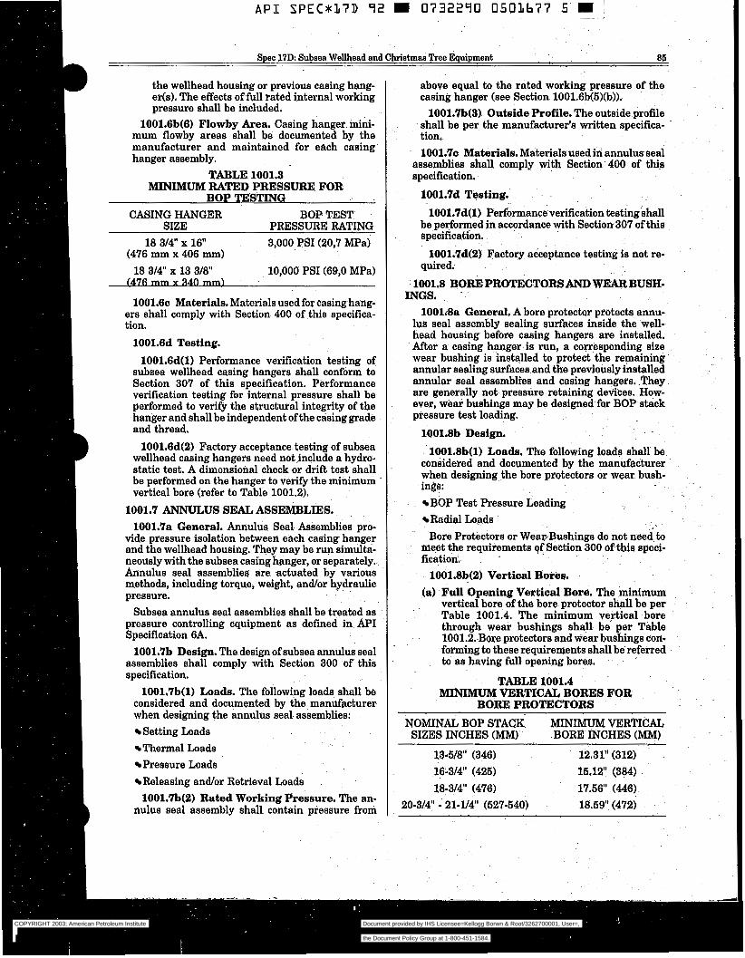
Spec 17D: Subsea Wellhead and Chrietmas nee Equipment 86-
the wellhead housing or previous casing hang- er@). The effects of full rated internal working pressure shall be included.
1001.6b(6) Flowby Area. Casing hanger mini- mum flowby areas shall be documented by the manufacturer and maintained for each casing hanger assembly.
TABLE 1001.3 MINIMUM RATED PRESSURE FOR
BOP TESTING CASING HANGER BOP. TEST
SIZE PRESSURE RATING 18 314 x 1 6 3,000 PSI (20,7 MPa)
18 314" x 13 318" 10,000 PSI (69,O MPa) (476 mm x 406 mm)
(476 -)
1001.6~ Materials. Materials used for casing hang- ers shall comply with Section 400 of this specifica- tion.
1001.6d Testing. 1001.6d(l) Performance verification testing of
subsea wellhead casing hangers shall conform to Section 307 of this specification. Performance verification testing for internal pressure shall be performed to verify the structural integrity of the hanger and shall be independent of the casing grade and thread.
1001.6d(2) Factory acceptance testing of subsea wellhead casing hangers need not include a hydro- static test. A dimensional check or drift test shall be performed on the hanger to verify the minimum vertical bore (refer to Table 1001.2).
1001.7 ANNULUS SEAL ASSEMBLIES. 1001.7a General. Annulus Seal Assemblies pro-
vide pressure isolation between each casing hanger and the wellhead housing. They may be run simulta- neously with the subsea casing hanger, or separately, Annulus seal assemblies are actuated by various methods, including torque, weight, and/or hydraulic pressure.
Subsea annulus seal assemblies shall be treated as pressure controlling equipment as defined in API Specification 6A.
1001.7b Design. The design of subsea annulus seal assemblies shall comply with Section 300 of this specification.
1001,7b(l) Loads. The following loads shall be considered and documented by the manufacturer when designing the annulus seal. assemblies:
Setting Loads Thermal Loads Pressure Loads Releasing and/or Retrieval Loads 1001.7b(2) Rated Working Pressure. The an-
nulus seal assembly shall contain pressure from
above equal to the rated working pressure of the casing hanger (see Section 100lq6b(5)(b)).
1001.7b(S) Outside Profile. The outside profile shall be per the manufacturer's written specifica- tion, 1001.7~ Materials. Materials used in annulusseal
assemblies shall comply with Section' 400 of this specification.
1001.7d Testing.
1001.7d(l) Performance verification testing shall be performed in accordance with Section 307 of this specification.
1001.7d(2) Factory acceptance testing is not re- quired.
1001.8 BOREPROTECTORSANDWEARBUSË- INGS.
1001i8a General. A bore protector protects ämu- lus seal assembly sealing surfaces inside the well- head housing before casing hangers are installed. After a casing hanger is run, a corresponding size wear bushing is installed to protect the remaining annular seding surfaces and the previously installed annular seal assemblies and casing hangers. .They are generally not pressure retaining devices. How- ever, wear bushings may be designed for BOP stack pressure test loading.
1001.8b Design. 1001.8b(l) Loads. The following loads shall be
considered and documented by the manufacturer when designing the bore protectors or wear bush- ings:
BOP Test Pressure Loading &dial Loads Bore Protec€ors or WeatBushings do not need to
meet the requirements of Section 300 of this speci- fication.
1001.8b(2) Vertical Bores. (a) Full Opening Vertical Bore. The minimum
vertical bore of the bore protector Ëhall be per Table 1001.4. The minimum vertical bore through wear bushings shall be per Table 1001.2. Bore protectors and wear bushings con- forming to these requirements shall be referred to as having full opening bores.
TABLE 1001.4 MINIMUM VERTICAL BORES FOR
BOREPROTECTORS
NOMINAL BOP STACK MINIMUM VERTICAL SIZES INCHES (MM). BORE INCHES (MM)
13-518" (346) 12.31" (312) 16:314" (425) 15.12' (384)
18-314" (476) 17.56l (446) 20-314: - 21-Y4" (527-540) 18.59' (472)
COPYRIGHT 2003; American Petroleum Institute
Document provided by IHS Licensee=Kellogg Borwn & Root/3262700001, User=, 09/10/2003 07:10:01 MDT Questions or comments about this message: please callthe Document Policy Group at 1-800-451-1584.
--`,,,``,```,`,`,``,`,,``,`,,`-`-`,,`,,`,`,,`---
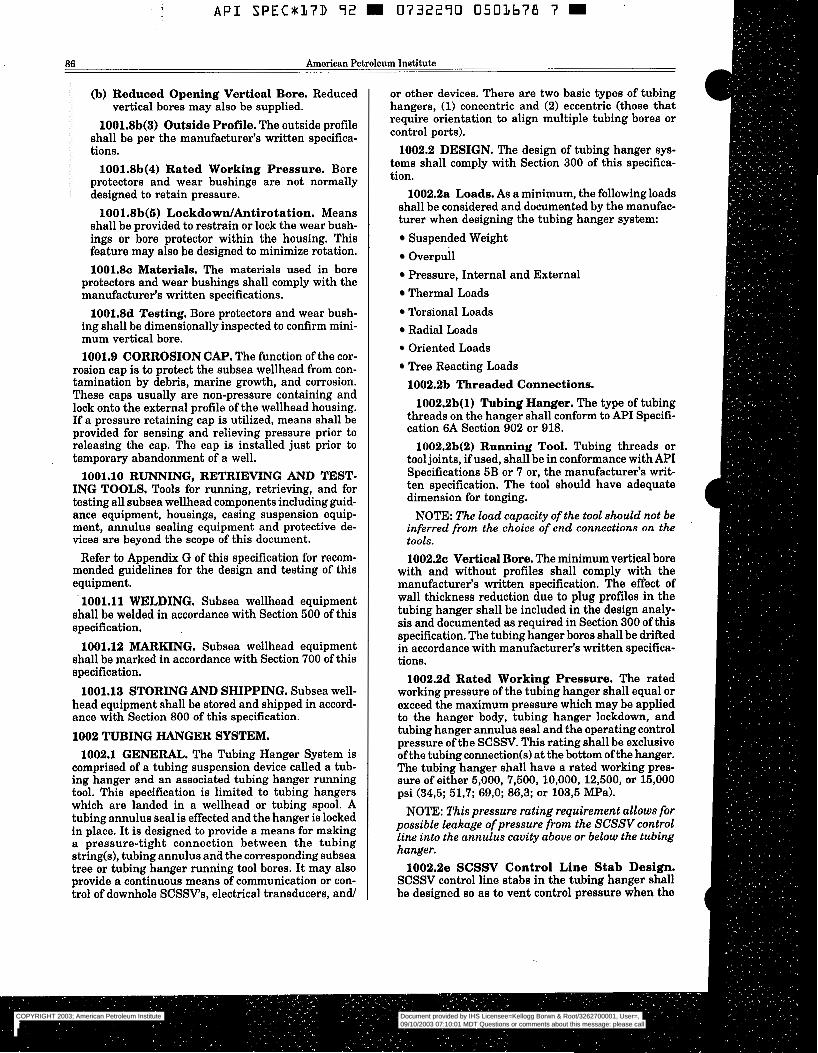
A P I S P E C * 1 7 D 72 m 0732270 0501678 7
86 American Petroleum Institute
(b) Reduced Opening Vertical Bore. Reduced
1001.8b(3) Outside Profile. The outside profile shall be per the manufacturer's written specifica- tions.
1001.8b(4) Rated Working Pressure. Bore protectors and wear bushings are not normally designed to retain pressure.
1001.8b(S) LockdowdAntirotation. Means shall be provided to restrain or lock the wear bush- ings or bore protector within the housing. This feature may also be designed to minimize rotation. 1001.8~ Materials. The materials used in bore
protectors and wear bushings shall comply with the manufacturer's written specifications.
1001.8d Testing. Bore protectors and wear bush- ing shall be dimensionally inspected to confirm mini- mum vertical bore. 1001.9 CORROSION CAP. The function of the cor-
rosion cap is to protect the subsea wellhead from con- tamination by debris, marine growth, and corrosion. These caps usually are non-pressure containing and lock onto the external profile of the wellhead housing. If a pressure retaining cap is utilized, means shall be provided for sensing and relieving pressure prior to releasing the cap. The cap is installed just prior to temporary abandonment of a well.
ING TOOLS. Tools for running, retrieving, and for testing all subsea wellhead components including guid- ance equipment, housings, casing suspension equip- ment, annulus sealing equipment and protective de- vices are beyond the scope of this document.
Refer to Appendix G of this specification for recom- mended guidelines for the design and testing of this equipment.
1001.11 WELDING. Subsea wellhead equipment shall be welded in accordance with Section 500 of this specification.
1001.12 MARKING. Subsea wellhead equipment shall be marked in accordance with Section 700 of this specification.
1001.13 STORING AND SHIPPING. Subsea well- head equipment shall be stored and shipped in accord- ance with Section 800 of this specification.
1002 TUBING HANGER SYSTEM. 1002.1 GENERAL. The Tubing Hanger System is
comprised of a tubing suspension device called a tub- ing hanger and an associated tubing hanger running tool. This specification is limited to tubing hangers which are landed in a wellhead or tubing spool. A tubing annulus seal is effected and the hanger is locked in place. It is designed to provide a means for making a pressure-tight connection between the tubing string(s), tubing annulus and the corresponding subsea tree or tubing~hanger running tool bores. It may also provide a continuous means of communication or con- trol of downhole SCSSVs, electrical transducers, and/
vertical bores may also be supplied.
1001.10 RUNNING, RETRIEVING AND TEST-
or other devices. There are two basic types of tubing hangers, (1) concentric and (2) eccentric (those that require orientation to align multiple tubing bores or control ports).
1002.2 DESIGN. The design of tubing hanger sys- tems shall comply with Section 300 of this specifica- tion.
1002.2a Loads. As a minimum, the following loads shall be considered and documented by the manufac- turer when designing the tubing hanger system:
Suspended Weight Overpull Pressure, Internal and External Thermal Loads Torsional Loads Radial Loads Oriented Loads Tree Reacting Loads 1002.2b Threaded Connections.
1002.2b(l) Tubing Hanger. The type of tubing threads on the hanger shall conform to API Specifi- cation 6A Section 902 or 918.
1002.2b(2) Running Tool. Tubing threads or tool joints, ifused, shall be in conformance with API Specifications 5B or 7 or, the manufacturer's writ- ten specification. The tool should have adequate dimension for tonging.
NOTE: The load capacity of the tool should not be inferred from the choice of end connections on the tools. 1002.2~ Vertical Bore. The minimum vertical bore
with and without profiles shall comply with the manufacturer's written specification. The effect of wall thickness reduction due to plug profiles in the tubing hanger shall be included in the design analy- sis and documented as required in Section 300 of this specification. The tubing hanger bores shall be drifted in accordance with manufacturer's written specifica- tions.
1002.2d Rated Working Pressure. The rated working pressure of the tubing hanger shall equal or exceed the maximum pressure which may be applied to the hanger body, tubing hanger lockdown, and tubing hanger annulus seal and the operating control pressure of the SCSSV. This rating shall be exclusive of the tubing connection(s) at the bottom of the hanger. The tubing hanger shall have a rated working pres- sure of either 5,000, 7,500, 10,000, 12,500, or 15,000 psi (34,5; 51,7; 69,O; 86,3; or 103,5 "a).
NOTE: This pressure rating requirement allows for possible leakage of pressure from the SCSSV control line into the annulus cavity above or below the tubing hanger.
1002.2e SCSSV Control Line Stab Design. SCSSV control line stabs in the tubing hanger shall be designed so as to vent control pressure when the
COPYRIGHT 2003; American Petroleum Institute
Document provided by IHS Licensee=Kellogg Borwn & Root/3262700001, User=, 09/10/2003 07:10:01 MDT Questions or comments about this message: please callthe Document Policy Group at 1-800-451-1584.
--`,,,``,```,`,`,``,`,,``,`,,`-`-`,,`,,`,`,,`---
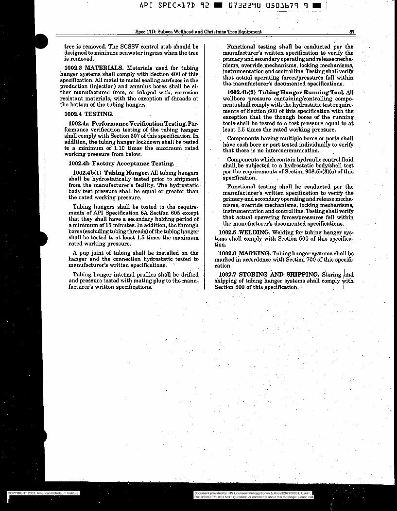
Spec 17D: Subaea Wellhead and Christmas "Ice Equipment a7
tree is removed. The SCSSV control stab should be designed to minimize seawater ingress when the tree is removed. 1002.3 MATERIALS, Materials used for tubing
hanger systems shall comply with Section 400 of this specification. All metal to metal sealing surfaces in the production (injection) and annulus bores shall be ei- ther manufactured from, or inlayed with, corrosion resistant materials, with the exception of threads at the bottom of the tubing hanger.
1002.4 TESTING. 1002.4a PerformanceVerification Testing. Per-
formance verification testing of the tubing hanger shall comply with Section 307 of this specification, In addition, the tubing hanger lockdown shall be tested to a minimum of 1.10 times the maximum rated working pressure from below.
1002.4b Factory Acceptance Testing. 1002.4b(l) Tubing Hanger. All tubing hangers
shall be hydrostatically tested prior to shipment from the manufacturer's facility. The hydrostatic body test pressure shall be equal or greater than the rated working pressure.
Tubing hangers shall be tested to the require- ments of API Specification 6A Sectton 605 except that they shall have a secondary holding period of a minimum of 15 minutes. In addition] the through bores (excluding tubing threads) of the tubing hanger shall be tested to at least 1.5 times the maximum rated working pressure.
A pup joint of tubing shall be installed on the hanger and the connection hydrostatic tested to manufacturer's written specifications.
Tubing. hanger internal profiles shall be drifted and pressure tested with mating plug to the manu- facturer's written specifications.
Functional testing shall be conducted per the manufacturer's written specification to verify the primary and secondary operating and release mecha- nisms, override mechanisms] locking mechanisms] instrumentation and control line. Testing shall verify that actual operating forces/pressures fall within the manufacturer's documented specifications.
1002.4b(2) Tubing Hanger Running Tool. All wellbore pressure containinghontrolling compo- nents shall comply with the hydrostatic test require- ments of Section 600 of this specification with the- exception that the through bores of the running tools shall be tested to a test pressure equal to at least 1.5 times the rated working pressure.
Components having multiple bores or ports shall have each bore or port tested individually to verify that there is no intercommunication,
Components which contain hydraulic control fluid shall.be subjected to a hydrostatic bodyhhell test per the requirements of Section 908.5b(3)(a) of this specification.
Functional testing shall be conducted per the manufacturer's written specification to verify the primary and secondary operating and release mecha- nisms] override mechanisms, locking mechanisms, instrumentation and control line. Testing shall verify that actual operating forcecdpressures fall within the manufacturer's documented specifications,
1002.6 WELDING. Welding for tubing hanger sys- tems shall comply with Section 500 of~this specifica- tion.
1002.6 IARKING. Tubing hanger systems shall be marked in accordance with Section 700 of this specifi- cation.
1002.7 STORING AND SHIPPING. Storing b d shipping of tubing hanger systems shall comply @th . Section 800 of this specification. r
~.
COPYRIGHT 2003; American Petroleum Institute
Document provided by IHS Licensee=Kellogg Borwn & Root/3262700001, User=, 09/10/2003 07:10:01 MDT Questions or comments about this message: please callthe Document Policy Group at 1-800-451-1584.
--`,,,``,```,`,`,``,`,,``,`,,`-`-`,,`,,`,`,,`---
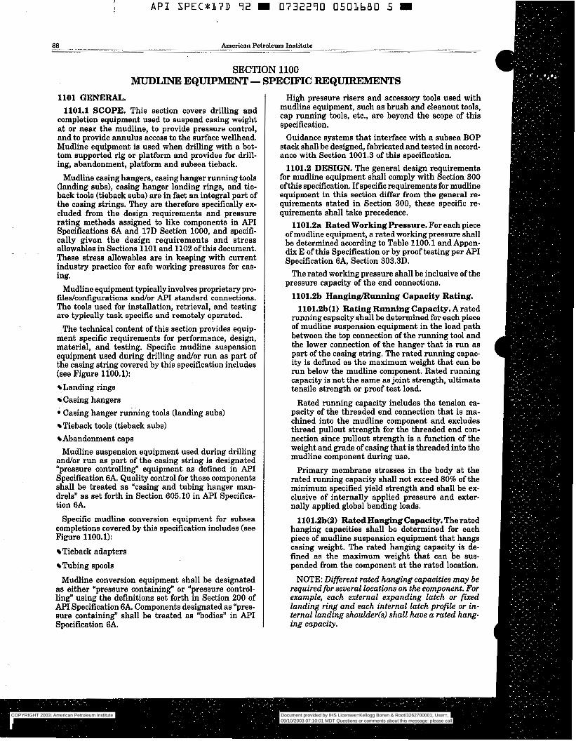
API SPEC*17D 92 0732290 0501680 5 m
aa American Petroleum Institute
SECTION 1100 MUDLINE EQUIPMENT - SPECIFIC REQUntEMENTS
1101 GENERAL. 1101.1 SCOPE. This section covers drilling and
completion equipment used to suspend casing weight at or near the mudline, to provide pressure control, and to provide annulus access to the surface wellhead. Mudline equipment is used when drilling with a bot- tom supported rig or platform and provides for drill- ing, abandonment, platform and subsea tieback.
Mudline casing hangers, casing hanger running tools (landing subs), casing hanger landing rings, and tie- back tools (tieback subs) are in fact an integral part of the casing strings. They are therefore specifically ex- cluded from the design requirements and pressure rating methods assigned to like components in API Specifications 6A and 17D Section 1000, and specifi- cally given the design requirements and stress allowables in Sections 1101 and 1102 of this document. These stress allowables are in keeping with current industry practice for safe working pressures for cas- ing.
Mudline equipment typically involves proprietary pro- files/configurations and/or A P I standard connections. The tools used for installation, retrieval, and testing are typically task specific and remotely operated.
The technical content of this section provides equip- ment specific requirements for performance, design, material, and testing. Specific mudline suspension equipment used during drilling andlor run as part of the casing stri,ng covered by this specification includes (see Figure 1100.1):
Landing rings Casing hangers
0 Casing hanger &ing tools (landing subs) Tieback tools (tieback subs) Abandonment caps Mudline suspension equipment used during drilling
and/or run as part of the casing string is designated "pressure controlling" equipment as defined in A P I Specification 6A. Quality control for these components shall be treated as "casing and tubing hanger man- drels" as set forth in Section 605.10 in API Specifica- tion 6A.
Specific mudline conversion equipment for subsea completions covered by this specification includes (see Figure 1100.1):
Tieback adapters Tubing spools
Mudline conversion equipment shall be designated as either "pressure containing" or "pressure control- ling" using the definitions set forth in Section 200 of API Specification 6A. Components designated as "pres- sure containing" shall be treated as "bodies" in API Specification 6A.
High pressure risers and accessory tools used with mudline equipment, such as brush and cleanout tools, cap running tools, etc., are beyond the scope of this specification.
Guidance systems that interface with a subsea BOP stack shall be designed, fabricated and tested in accord- ance with Section 1001.3 of this specification.
1101.2 DESIGN. The general design requirements for mudline equipment shall comply with Section 300 of this specification. If specific requirements for mudline equipment in this section differ from the general re- quirements stated in Section 300, these specific re- quirements shall take precedence.
1101.2a Rated Working Pressure. For each piece of mudline equipment, a rated working pressure shall be determined according to Table 1100.1 and Appen- dix E of this Specification or by proof testing per API Specification 6A, Section 303.3D.
The rated working pressure shall be inclusive of the pressure capacity of the end connections.
1101.2b Hanging/Running Capacity Rating. 1101.2b(l) Rating Running Capacity. A rated
running capacity shall be determined for each piece of mudline suspension equipment in the load path between the top connection of the running tool and the lower connection of the hanger that is run as part of the casing string. The rated running capac- ity is defined as the maximum weight that can be run below the mudline component. Rated running capacity is not the same as joint strength, ultimate tensile strength or proof test load.
Rated running capacity includes the tension ca- pacity of the threaded end connection that is ma- chined into the mudline component and excludes thread pullout strength for the threaded end con- nection since pullout strength is a function of the weight and grade of casing that is threaded into the mudline component during use.
Primary membrane stresses in the body at the rated running capacity shall not exceed 80% of the minimum specified yield strength and shall be ex- clusive of internally applied pressure and exter- nally applied global bending loads.
1101.2b(2) Rated Hanging Capacity. The rated hanging capacities shall be determined for each piece of mudline suspension equipment that hangs casing weight. The rated hanging capacity is de- fined as the maximum weight that can be sus- pended from the component at the rated location.
NOTE: Different rated hanging capacities may be required for several locations on the component. For example, each external expanding latch or fixed landing ring and each internal latch profile or in- ternal landing shoulder(s) shall have a rated hang- ing capacity.
COPYRIGHT 2003; American Petroleum Institute
Document provided by IHS Licensee=Kellogg Borwn & Root/3262700001, User=, 09/10/2003 07:10:01 MDT Questions or comments about this message: please callthe Document Policy Group at 1-800-451-1584.
--`,,,``,```,`,`,``,`,,``,`,,`-`-`,,`,,`,`,,`---
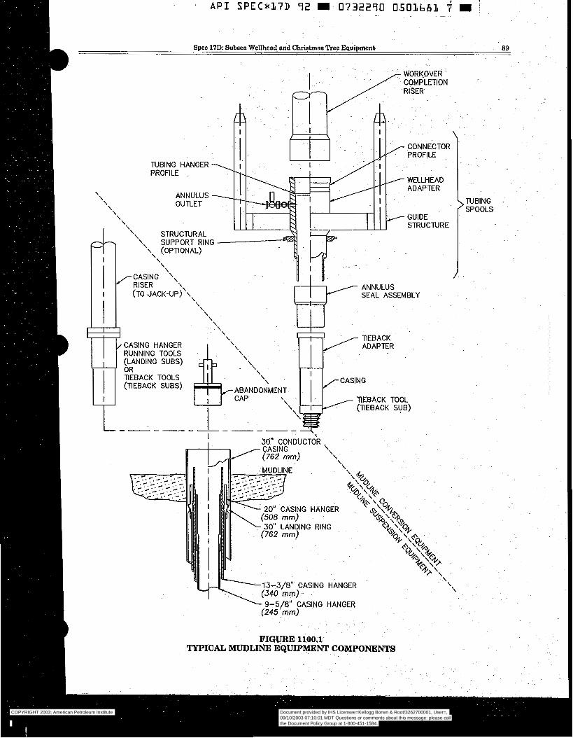
API SPEC*l7D 92 m 0732290 050lb8L d m ~.
Spec 17D Subsea Wellhead and Chriatmaa Tree Equipment 89
WORKOVER COMPLETION RISER
J, i i f
i t ~
CONNECTOR PROFILE
TUBING HANGER PROFILE
WELLHEAD ADAPTER
\ ANNULUS OUTLET
\ \ \ \ \ \
GUIDE \ STRUCTURE \\ STRUCTURAL
1 \\ SUPPORT RING \ (OPTIONAL)
\ r \ \
r CASING \\ RISER \
(TO JACK-UP)\\\ \
CASING HANGER RUNNING TOOLS (LANDING SUBS) OR TIEBACK TOOLS (TIEBACK SUBS)
\ \ \ \
ANNULUS SEAL ASSEMBLY
TIEBACK ADAPTER
\ /CASING ABANDONMENT CAP ~ \
\ TIEBACK TOOL I \
\ (TIEBACK SUB)
\
O” LANDING RING
\ \
9-5/8” CASING HANGER (245. mm]
FIGURE 1100.1 TYPICAL MUDLINE EQUIPMENT COMPONENTS
COPYRIGHT 2003; American Petroleum Institute
Document provided by IHS Licensee=Kellogg Borwn & Root/3262700001, User=, 09/10/2003 07:10:01 MDT Questions or comments about this message: please callthe Document Policy Group at 1-800-451-1584.
--`,,,``,```,`,`,``,`,,``,`,,`-`-`,,`,,`,`,,`---
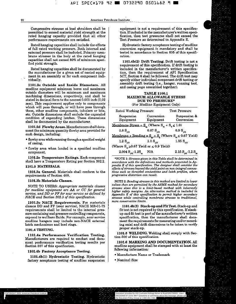
~
A P I SPECU37D 92 R 0732290 0503682 9 m
90 American Petroleum Institute
Compressive stresses at load shoulders shall be permitted to exceed material yield strength at the rated hanging capacity provided that all other performance requirements are satisfied.
Rated hanging capacities shall include the effects of full rated working pressure. Both internal and external pressure shall be included. Primary mem- brane stresses in the body at the rated hanging capacities shall not exceed 80% of minimum speci- fied yield strength.
Rated hanging capacities shall be documented by the manufacturer for a given set of nested equip- ment in an assembly or for each component indi-
1101.2~ Outside and Inside Diameters. All mudline equipment minimum bores and maximum outside diameters will be minimum and maximum machining dimensions, respectively, and shall be stated in decimal form to the nearest 0.001 inch (0,02 mm). This requirement applies only to components which will pass through, or will have pass through them, other mudline components, tubulars or bits, etc, Outside dimensions shall exclude the expanded condition of expanding latches. These dimensions shall be documented by the manufacturer.
1101.2d Flowby Areas. Manufacturers shall docu- ment the minimum quantity flowby area provided for each design, including:
flowby area while running through a specified weight of casing,
‘0 flowby area when landed in a specified mudline component. 1101.2e Temperature Ratings. Each component
shall have a’Temperature Rating per Section 302.2. 1101.3 MATERIALS.
- vidually.
1101.3a General. Materials shall conform to the
1101.3b Materials Classes. NOTE TO USERS: Appropriate materials classes
for mudline equipment are AA or CC for general service, and DD or FF for sour service as defined by NACE and Section 302.3 of this specification.
1101.3~ NACE Requirements. For materials classes DD and FF (sour service), NACE MR-01-75 requirements shall be limited to the internal pres- sure containing and pressure controlling components, exposed to wellbore fluids. For example, sour service mudline hangers may include non-NACE external latch mechanisms and load rings. 1101.4 TESTING.
requirements of Section 400.
1101.4a Performance Verification Testing. Manufacturers are required to conduct and docu- ment performance verification testing results per Section 307 of this specification.
1101.4b Factory Acceptance Testing. 1101.4b(l) Hydrostatic Testing. Hydrostatic
factory acceptance testing of mudline suspension
equipment is not a requirement of this specifica- tion. If included in the manufacturer‘s written speci- fication, then test pressures shall not exceed the Test Pressure as determined in Appendix E.
Hydrostatic factory acceptance testing of mudline conversion equipment is mandatory and shall be tested in accordance to Section 605 of this specifi- cation.
1101.4b(2) Drift Testing. Drift testing is not a requirement of this specification. If drift testing is included in the manufacturer’s written specifica- tion, then the requirement of API Specification 5CT, Section 6 shall be followed. The drift test may specify either individual component drift testing or assembly drift testing (i.e., hanger, running tool, and casing pups assembled together).
TABLE 1100.1 MAXIMU” ALLOWABLE STRESS
DUE TO PRESSURE* (For Mudline Equipment Only)
Rated Working Pressure Test Pressure
Suspension Conversion Suspension & Equipment Equipment Conversion
Stress = S (Where Sm + Sb< 1.0)
O’’ ‘yld 0.67 Syld ‘yld
ane + Bengine = S e (Where Sm< 0.67 Yield)
‘,Id ‘‘O ‘yld 1.35 Syld (Where Sm 20.67 Yield or 0.9 Yield)
2.004 SYld-1.2Sm NIA 2.15 Sfld-1.2 Sm
*NOTE 1: Stresses given in this Table shall be determined in accordance with the definitions and methods presented in Ap- pendix E of this specification. The designer shall consider the effects of stresses beyond the yieldpoint on non-integral connec- tions such as threaded connections and latch profiles, where progressive distortion can result.
NOTE 2: Bending stresses in this method are limited to lower values than are permitted by the ASME method for secondary stresses since this is a limit-based method with inherently higher safety margins. An alternative method is included in Appendix E of this specification to permit higher secondary stresses while controlling membrane stresses to traditional, more conservative limits.
1101.4b(3) Stack-up and Fit Test. Stack-up and fit test is not required by this specification. If stack- up and fit test is part of the manufacturer’s written specification, then the manufacturer shall docu- ment the requirements for measuring and/or record- ing axial and drift dimensions to be taken to verify proper stack-up.
1101.6 WELDING. Welding shall comply with Sec- tion 500 of this specification.
1101.6 MARKING AND DOCUMENTATION. All mudline equipment shall be stamped with at least the following information:
Manufacture Name or Trademark Nominal Size
COPYRIGHT 2003; American Petroleum Institute
Document provided by IHS Licensee=Kellogg Borwn & Root/3262700001, User=, 09/10/2003 07:10:01 MDT Questions or comments about this message: please callthe Document Policy Group at 1-800-451-1584.
--`,,,``,```,`,`,``,`,,``,`,,`-`-`,,`,,`,`,,`---
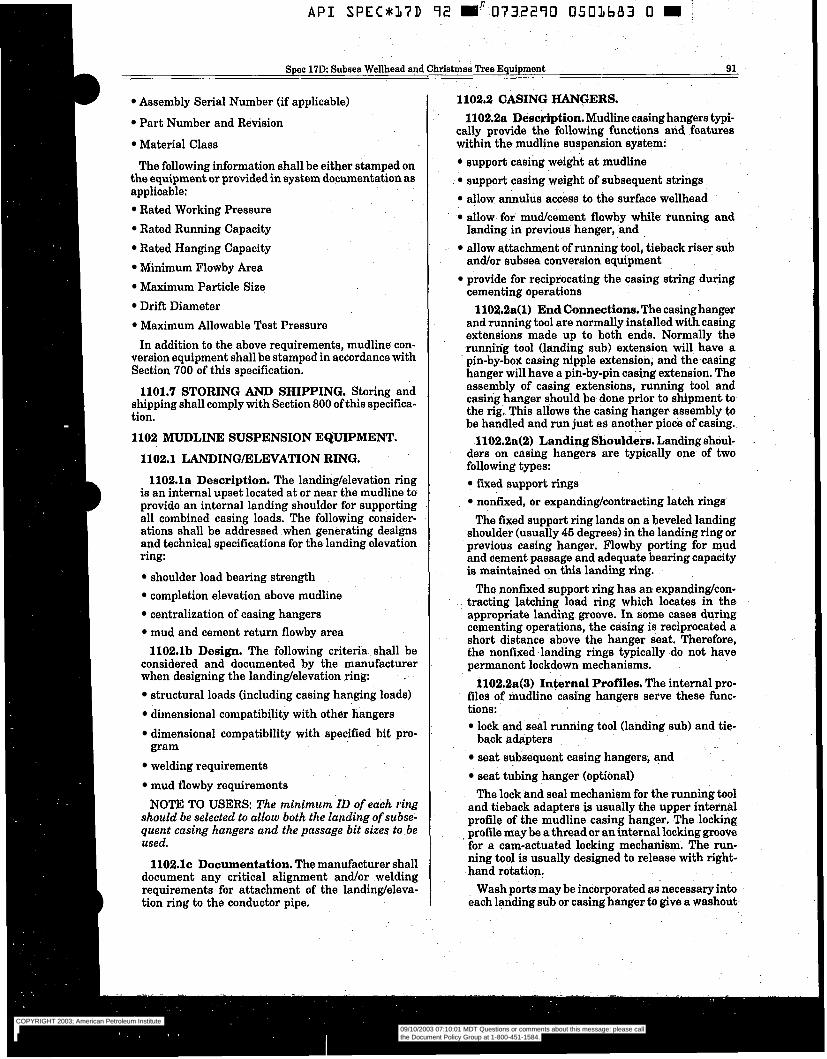
Spec 17D Subsea Wellhead and Christmas Tree Equipment 91
Assembly Serial Number (if applicable)
Part Number and Revision
Material Class
The following information shall be either stamped on the equipment or provided in system documentation as applicable:
Rated Working Pressure Rated Running Capacity Rated Hanging Capacity Minimum Flowby Area Maximum Particle Size Drift Diameter Maximum Allowable Test Pressure In addition to the above requirements, mudline con-
version equipment shall be stamped in accordance with Section 700 of this specification.
1101.7 STORING AND SHIPPING. Storing and shipping shall comply with Section 800 of this specifica- tion.
1102 MUDLINE SUSPENSION EQUIPMENT.
1102.1 LANDINGELEVATION RING.
1102.la Description. The landing/elevation ring is an internal upset located at or near the mudline to provide an internal landing shoulder for supporting all combined casing loads. The following consider- ations shall be addressed when generating designs and technical specifications for the landing elevation ring:
shoulder load bearing strength completion elevation above mudline centralization of casing hangers mud and cement return flowby area 1102.lb Design. The following criteria shall be
considered and documented by the manufacturer when designing the landing/elevation ring:
structural loads (including casing hanging loads) dimensional compatibility with other hangers dimensional compatibility with specified bit pro-
welding requirements mud flowby requirements NOTE TO USERS: The minimum ID of each ring
should be selected to allow both the landing of subse- quent casing hangers and the passage bit sizes to be used.
gram
1102.1~ Documentation. The manufacturer shall document any critical alignment and/or welding requirements for attachment of the landing/eleva- tion ring to the conductor pipe.
1102.2 CASING HANGERS. 1102.2a Description. Mudline casing hangers typi-
cally provide the following functions and features within the mudline suspension system:
support casing weight at mudline support casing weight of subsequent strings allow annulus access to the surface wellhead allow for mud/cement flowby while running and landing in previous hanger, and allow attachment of running tool, tieback riser sub and/or subsea conversion equipment provide for reciprocating the casing string during cementing operations
1102.2a(l) End Connections. The casing hanger and running tool are normally installed withcasing extensions made up to both ends. Normally the runniñg tool (landing sub) extension will have a pin-by-box casing nipple extension, and the casing hanger will have a pin-by-pin casing extension. The assembly of casing extensions, running tool and casing hanger should be done prior to shipment to the rig. This allows the casing hanger assembly to be handled and run just as another piece of casing.
1102.2a(2) Landing Shoulders. Landing shoul- ders on casing hangers are typically one of two following types:
fixed support rings nonfixed, or expanding/contracting latch rings The fixed support ring lands on a beveled landing
shoulder (usually 45 degrees) in the landing ring or previous casing hanger. Flowby porting for mud and cement passage and adequate bearing capacity is maintained on this landing ring.
The nonfixed support ring has an expandinglcon- tracting latching load ring which locates in the appropriate landing groove. In some cases during cementing Operations, the casing is reciprocated a short distance above the hanger seat. Therefore, the nonfixed landing rings typically do not have permanent lockdown mechanisms.
1102.2a(3) Internal Profiles. The internal pro- files of mudline casing hangers serve these func- tions:
lock and seal running tool (landing sub) and tie-
seat subsequent casing hangers, and seat tubing hanger (optional) The lock and seal mechanism for the running tool
and tieback adapters is usually the upper internal profile of the mudline casing hanger. The locking profile may be a thread or an internal locking groove for a cam-actuated locking mechanism. The run- ning tool is usually designed to release with right- hand rotation.
Wash ports may be incorporated as-necessary into each landing sub or casing hanger to give a washout-
back adapters
COPYRIGHT 2003; American Petroleum Institute
Document provided by IHS Licensee=Kellogg Borwn & Root/3262700001, User=, 09/10/2003 07:10:01 MDT Questions or comments about this message: please callthe Document Policy Group at 1-800-451-1584.
--`,,,``,```,`,`,``,`,,``,`,,`-`-`,,`,,`,`,,`---
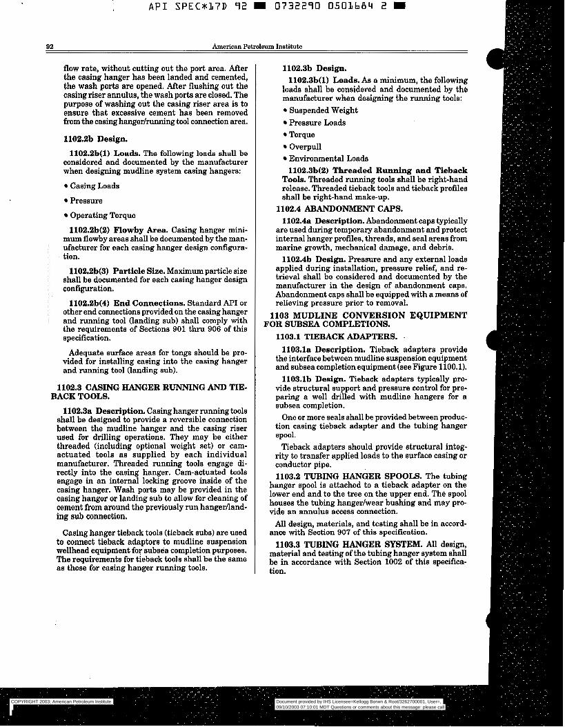
API S P E C 8 1 7 D 92 a 0 7 3 2 2 9 0 0501684 2 m
92 American Petroleum Institute
flow rate, without cutting out the port area. After the casing hanger has been landed and cemented, the wash ports are opened, After flushing out the casing riser annulus, the wash ports are closed. The purpose of washing out the casing riser area is to ensure that excessive cement has been removed from the casing hangedrunning tool connection area.
1102.2b Design.
1102.2b(l) Loads. The following loads shall be considered and documented by the manufacturer when designing mudline system casing hangers:
Casing Loads
Pressure
Operating Torque
1102.2b(2) Flowby Area. Casing hanger mini- mum flowby areas shall be documented by the man- ufacturer for each casing hanger design configura- tion.
1102.2b(3) Particle Size, Maximum particle size shall be documented for each casing hanger design configuration.
1102.2b(4) End Connections. Standard A P I or other end connections provided on the casing hanger and running tool (landing sub) shall comply with the requirements of Sections 901 thru 906 of this specification.
Adequate surface areas for tongs should be pro- vided for installing casing into the casing hanger and running tool (landing sub).
1102.3 CASING HANGER RUNNING AND TIE- BACK TOOLS.
1102.3a Description. Casing hanger running tools shall be designed to provide a reversible connection between the mudline hanger and the casing riser used for drilling operations. They may be either threaded (including optional weight set) or cam- actuated tools as supplied by each individual manufacturer. Threaded running tools engage di- rectly into the casing hanger. Cam-actuated tools engage in an internal locking groove inside of the casing hanger. Wash ports may be provided in the casing hanger or landing sub to allow for cleaning of cement from around the previously run hangerlland- ing sub connection.
Casing hanger tieback tools (tieback subs) are used to connect tieback adaptors to mudline suspension wellhead equipment for subsea completion purposes. The requirements for tieback tools shall be the same as those for casing hanger running tools.
1102.3b Design. 1102.3b(l) Loads. As a minimum, the following
loads shall be considered and documented by th6 manufacturer when designing the running tools:
Suspended Weight Pressure Loads Torque Overpull Environmental Loads 1102.3b(2) Threaded Running and Tieback
Tools. Threaded running tools shall be right-hand release. Threaded tieback tools and tieback profiles shall be right-hand make-up.
1102.4 ABANDONMENT CAPS. 1102.4a Description. Abandonment caps typically
are used during temporary abandonment and protect internal hanger profiles, threads, and seal areas from marine growth, mechanical damage, and debris.
1102.4b Design. Pressure and any external loads applied during installation, pressure relief, and re- trieval shall be considered and documented by the manufacturer in the design of abandonment caps. Abandonment caps shall be equipped with a means of relieving pressure prior to removal.
1103 MUDLINE CONVERSION EQUIPMENT FOR SUBSEA COMPLETIONS.
1103.1 TIEBACK ADAPTERS. -
1103.la Description. Tieback adapters provide the interface between mudline suspension equipment and subsea completion equipment (see Figure 1100.1).
1103.lb Design. Tieback adapters typically pro- vide structural support and pressure control for pre- paring a well drilled with mudline hangers for a subsea completion.
One or more seals shall be provided between produc- tion casing tieback adapter and the tubing hanger spool.
Tieback adapters should provide structural integ- rity to transfer applied loads to the surface casing or conductor pipe. 1103.2 TUBING HANGER SPOOLS. The tubing
hanger spool is attached to a tieback adapter on the lower end and to the tree on the upper end. The spool houses the tubing hangerlwear bushing and may pro- vide an annulus access connection.
All design, materials, and testing shall be in accord- ance with Section 907 of this specification.
1103.3 TUBING HANGER SYSTEM. All design, material and testing of the tubing hanger system shall be in accordance with Section 1002 of this specifica- tion.
COPYRIGHT 2003; American Petroleum Institute
Document provided by IHS Licensee=Kellogg Borwn & Root/3262700001, User=, 09/10/2003 07:10:01 MDT Questions or comments about this message: please callthe Document Policy Group at 1-800-451-1584.
--`,,,``,```,`,`,``,`,,``,`,,`-`-`,,`,,`,`,,`---
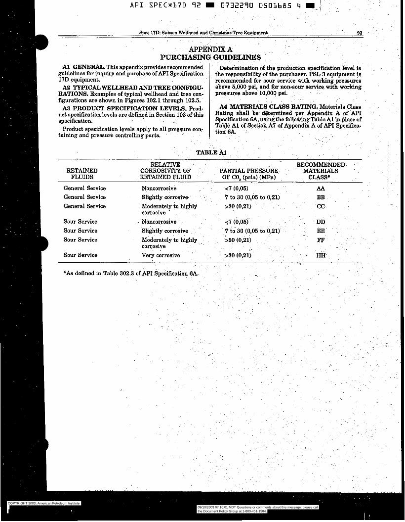
A l GENERAL. This appendix provides recommended guidelines for inquiry and.purchase of A P I Specification 17D equipment.
RATIONS. Examples of typical wellhead and tree con- figurations are shown in Figures 102.1 through 102.5.
uct specification levels are defined in Section 103 ofthis specification. . . .~
Product specification levels apply to all pressure con- taining and pressure controlling parts.
A2 TYPICAZIWELLHEAD AND TREE CONFIGU-
AS PRODUCT SPECIFICATION LEVELS. Prod-
I
A P I SPEC*KL7D 92 m 0732290 050LbA5 4 m - ,i
Spec 17D: Subsea Wellhead and C h r i s ~ h y Tree Equipment 93 - .
APPËNDM A PURCHASING GUIDELINES
Determination of the production specification level is the responsibility of the purchaser. PSL 3 equipment i s recommended for sour service with working pressures above 5,000 psi, and for non-sour service with working pressures above- 10,000 psi.. .. ~ .- .
A4 MATERIALS CLASS RATING..Materials Class Rating shall be. determined per Appendix A of API Specification 6A, using the following Table Al in place of Table A l of Section A7 of Appendix A of API Specifica- tion 6A. ~~
..
COPYRIGHT 2003; American Petroleum Institute
Document provided by IHS Licensee=Kellogg Borwn & Root/3262700001, User=, 09/10/2003 07:10:01 MDT Questions or comments about this message: please callthe Document Policy Group at 1-800-451-1584.
--`,,,``,```,`,`,``,`,,``,`,,`-`-`,,`,,`,`,,`---
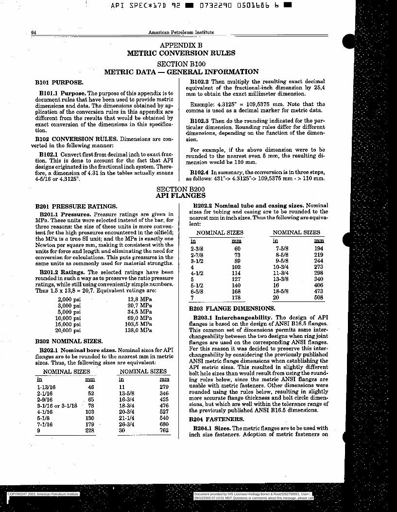
A P I S P E C x 1 7 D 92 E 0732290 0501686 b E
94 American Petroleum Institute
APPENDIX B RlETRIC CONVERSION RULES
SECTION B100 METRIC DATA - GENERAL INFORMATION
B101 PURPOSE.
B101.1 Purpose, The purpose of this appendix is to document rules that have been used to provide metric dimensions and data, The dimensions obtained by ap- plication of the conversion rules in this appendix are different from the results that would be obtained by exact conversion of the dimensions in this specifica- tion. B102 CONVERSION RULES. Dimensions are con-
B102.2 Then multiply the resulting exact decimal equivalent of the fractional-inch dimension by 25,4 mm to obtain the exact millimeter dimension.
Example: 4.3125" = 109,5375 mm. Note that the comma is used as a decimal marker for metric data.
B102.3 Then do the rounding indicated for the par- ticular dimension. Rounding rules differ for different dimensions, depending on the function of the dimen- sion.
verted in the following manner: For example, if the above dimension were to be
B102.1 ConVert first from decimal inch to exact frac- rounded to the even 5 -, the resulting di- tion. This is done to account for the fact that API mension would be 110 mm. designs originated in the fractional inch system. There- fore, a dimension of 4.31 in the tables actually means B102.4 In summary, the conversion is in three steps, 4-5/16 or 4.3125". as follows: 431"-> 4.3125"-> 109,5375 mm - > 110 mm.
SECTION B200 API FLANGES
B201 PRESSURE RATINGS. B201.1 Pressures. Pressure ratings are given in
MPa. These units were selected instead of the bar, for three reasons: the size of these units is more conven- ient for the high pressures encountered in the oilfield; the MPa is a true SI unit; and the MPa is exactly one Newton per square mm, making it consistent with the units for force and length and eliminating the need for conversion for calculations. This puts pressures in the same units as commonly used for material strengths. B201.2 Ratings. The selected ratings have been
rounded in such a way as to preserve the ratio pressure ratings, while still using conveniently simple numbers. Thus 1.5 x 13,8 = 20,7. Equivalent ratings are:
2,000 psi 13,8 MPa 3,000 psi 20,7 MPa 5,000 psi 34,5 MPa 10,000 psi 69,O MPa 15,000 psi 103,5 MPa 20,000 psi 138,O MPa
B202 NOMINAL SIZES. B202.1 Nominal bore sizes. Nominal sizes for API
flanges are to be rounded to the nearest mm in metric sizes. Thus, the following sizes are equivalent:
NOMINAL SIZES NOMINAL SIZES in mm in mm 1-13/16 46 11 279 2-1/16 52 13-518 346 2-9116 65 16-314 425 3-1/16 or 3-1/18 78 18-314 476 4-1/16 103 20-314 527 5-1/8 130 21-1/4 540 7-1/16 179 . 26-314 680 9 228 30 762
B202.2 Nominal tube and casing sizes. Nominal sizes for tubing and casing are to be rounded to the nearest mm in inch sizes. Thus the following are equiva- lent:
NOMINAL SIZES NOMINAL SIZES in mm in pllp
2-318 60 7-518 194 2-718 73 8-518 219 3-ll2 89 9-518 244 4 102 10-314 273 4- 1/2 114 11-314 298 5 127 13-318 340 5- 1/2 140 16 406 6-518 168 18-518 473 7 178 20 508
B203 FLANGE DIMENSIONS. B203.1 Interchangeability. The design of API
flanges is based on the design of ANSI B16.5 flanges. This common set of dimensions permits some inter- changeability between the two designs when ring joint flanges are used on the corresponding ANSI flanges. For this reason it was decided to preserve this inter- changeability by considering the previously published ANSI metric flange dimensions when establishing the API metric sizes. This resulted in slightly different bolt hole sizes than would result from using the round- ing rules below, since the metric ANSI flanges are usable with metric fasteners. Other dimensions were rounded using the rules below, resulting in slightly more accurate flange thickness and bolt circle dimen- sions, but which are well within the tolerance range of the previously published ANSI B16.5 dimensions. B204 FASTENERS. B204.1 Sizes. The metric flanges are to be used with
inch size fasteners. Adoption of metric fasteners on
COPYRIGHT 2003; American Petroleum Institute
Document provided by IHS Licensee=Kellogg Borwn & Root/3262700001, User=, 09/10/2003 07:10:01 MDT Questions or comments about this message: please callthe Document Policy Group at 1-800-451-1584.
--`,,,``,```,`,`,``,`,,``,`,,`-`-`,,`,,`,`,,`---
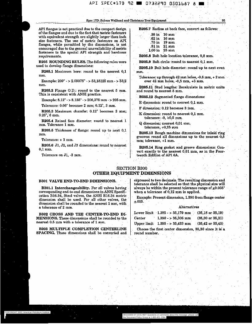
A P I S P E C * 1 7 D 72 m 0732270 0503687 8 m 1 . .
"
- ~ ~ ~~ ~~
D Specl7D Subsea Wellhead and Christmas Tree Equipment 96
API flanges is not practical due to the compact design B206.7 $dius at back face, convert as follows: of the flanges and due to the fact that metric fasteners with equivalent strength are slightly larger than inch size fasteners. The use of metric fasteners on API . . flanges, while permitted by the dimensions, is not encouraged due to the general unavailability of metric fasteners to the special API strength and hardness .
requirements. B206.8 Bolt hole location tolerance, 0,8 mm.
,38in 10 mm .62 in 16 mm .75 in 19.mm .81in 21 mm
1.00 in 25 mm
B206 ROUNDING RULES. The following rules were
B206.1 Maximum bore: round to the nearest 0,l
Example: 2 0 9 - > 2.09375" - > 53,18125 mm - >63,2
B206.2 Flange O.D.: round to the nearest 5 mm.
Example: 8.12" - > 8.125' - > 206,375 mm - > 205 m. Tolerance: 0.06" becomes 2 mm; 0.12", 3 mm. B206.3 Maximum chamfer: 0.12" becomes 3 mm;
B206.4 Raised face diameter: round to nearest 1
used to develop flange dimensions:
mm. mm. This is consistent with ANSI practice.
0.25",'6 mm.
mm. Tolerance 1 mm. B206.6 Thickness of flange: round up to next 0,l
Tolerance: + 3 mm. mm.
B206.9 Bolt circle: round to nearest O j l mm. B206.10 Bolt hole diameter: round up to next even
Tolerance: up through 42 mm holes, -0;5 mm, + 2 mm
B206.11 Stud lengths: Recalculate in metric units
B205.12 Segmented flange dimensions: . E dimension round tö nearest 0, l mm.
F dimension: 0.12 becomes 3 inm. K dimension: round to nearest 0,l mm.
Q dimensionmearest 0,Ol mm,
B206,13 Rough machine dimensions for inlaid ring grooves: round all dimensions up to the nearest- 0,5 mm; tolerance. +1 mm.
mm. over 42 mm holes, -0,5 mm, +3 mm.
and round to nearest 5 mm.
tolerance: -0, +0,5 mm.
tolerance, +0,25 mm
B206.6 Jl,J2, and J3 dimensions: round to nearest
Tolerance on J1, -3 mm. teenth Edition of API 6A.
B206.14 Ring gasket and groove dimensibns: Con- vert exactly to the nearest 0,Ol mm, as in the Four- 0, l mm.
SECTION B300 - .
OTHER EQUIPMENT DIMENSIONS
B301 VALVE END-TO-END DIMENSIONS, .
B301.1 Interchangeability. For all valves having corresponding end-to-end dimensions in ANSI Specifi- cation B16.34, Steel valves, the ANSI B16.34 metric dimension shall be used. For all other valves, the. dimension shall be rounded to the nearest 1 mm, with a tolerance of 2 mm.
expressed to two decimals. The reshting dimension and tolerance shall be selected so that the physical size will always be-within the present tolerance range of f0.005" when a tolerance of 0,12 mm is applied.
Example: Present dimension, 1.390 from flange center k.005,
Alternatives
B302 CROSS TEE CENmR-TO.Em DI; Lower limit. 1.385 - > 35,179 (35,18 or 35,191 MENSIONS. These dimensions shall be rounded to the . Center 1.390 - > 35,306 mm (35,30 or 35,311 nearest 0.5 mm with a tolerance of 1 mm. Upper limit 1.395 - -> 35,433 mm (85,42 or 35,431. B303 MULTIPLE COMPLETION CENTERLINE Choose the fist-center dimension, 35,30 since it i É a
SPACING. These dimensions shall be converted and round number.
- .
COPYRIGHT 2003; American Petroleum Institute
Document provided by IHS Licensee=Kellogg Borwn & Root/3262700001, User=, 09/10/2003 07:10:01 MDT Questions or comments about this message: please callthe Document Policy Group at 1-800-451-1584.
--`,,,``,```,`,`,``,`,,``,`,,`-`-`,,`,,`,`,,`---
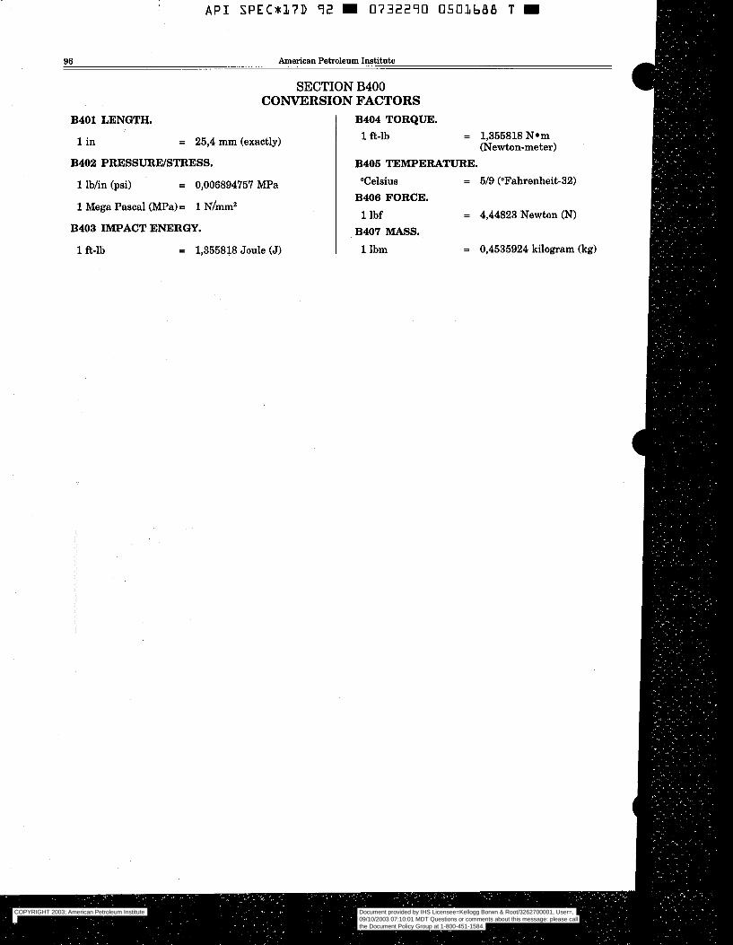
A P I S P E C U L 7 D 9 2 m 0732290 0583688 T m I
96 American Petroleum Institute
SECTION B400 CONVERSION FACTORS
B401 LENGTH. I B404 TORQUE.
1 in = 25,4 mm (exactly) 1 ft-lb = 1,355818 Nem (Newton-meter)
B402 PRESSURWSTRESS. I B406 TEMPERATURE.
1 lbhn (psi) = 0,006894757 MPa "Celsius I B406 FORCE. 1 lbf
= 5/9 ("Fahrenheit-32)
= 4,44823 Newton (N) B403 IMPACT ENERGY. B407 MASS.
1 fi-lb = 1.355818 Joule (J) 1 1Ibm = 0,4535924 kilogram (kg)
COPYRIGHT 2003; American Petroleum Institute
Document provided by IHS Licensee=Kellogg Borwn & Root/3262700001, User=, 09/10/2003 07:10:01 MDT Questions or comments about this message: please callthe Document Policy Group at 1-800-451-1584.
--`,,,``,```,`,`,``,`,,``,`,,`-`-`,,`,,`,`,,`---
. .
.- Spec 17D: Subsea Wellhead and Christmas Tree Equipment 97 - .
APPENDIX C- . . -~
CANDIDATE API STANDARD INTERVENTION FMTURES
Figure Description ~. - Number ~
Grasping (3921.1 Docking C92ï.2 Docking C921.3 Linearhtary c921.4 Linear Rotary C921.6 Rotary/Fluid Coupling - C921.7 Docking/Rotary/Fluid Coupling C921.8 Docking/Rotary . " ~ (2921.9 Fluid Coupling ~ . - C921.10 Fluid Coupling - " (3921.11
.~
. - -- C921.5 r
- .
~. .~ ,.
~~
. .
COPYRIGHT 2003; American Petroleum Institute
Document provided by IHS Licensee=Kellogg Borwn & Root/3262700001, User=, 09/10/2003 07:10:01 MDT Questions or comments about this message: please callthe Document Policy Group at 1-800-451-1584.
--`,,,``,```,`,`,``,`,,``,`,,`-`-`,,`,,`,`,,`---
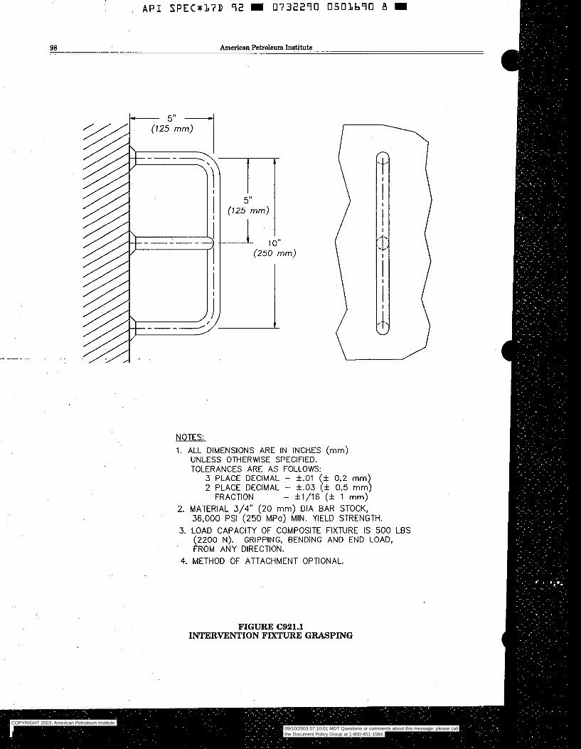
5” (125 mm)
i,
I
(250 mm) \
NOTES:
1. ALL DIMENSIONS ARE IN INCHES (mm) UNLESS OTHERWSE SPECIFIED. TOLERANCES ARE AS FOLLOWS:
3 PLACE DECIMAL - f.O1 (i 0.2 mm) 2 PLACE DECIMAL - f.03 (f 0 3 mm)
FRACTION - f1/16 (* 1 mm) 2. MATERIAL 3/4” (20 mm) DIA BAR STOCK,
36,000 PSI (250 MPa) MIN. YIELD STRENGTH. 3. LOAD CAPACITY OF COMPOSITE FIXTURE IS 500 LBS
(2200 N). GRIPPING, BENDING AND END LOAD, FROM ANY DIRECTION.
4. METHOD OF ATTACHMENT OPTIONAL.
FIGURE C921.1 INTERVENTION FIXTURE GRASPING
COPYRIGHT 2003; American Petroleum Institute
Document provided by IHS Licensee=Kellogg Borwn & Root/3262700001, User=, 09/10/2003 07:10:01 MDT Questions or comments about this message: please callthe Document Policy Group at 1-800-451-1584.
--`,,,``,```,`,`,``,`,,``,`,,`-`-`,,`,,`,`,,`---
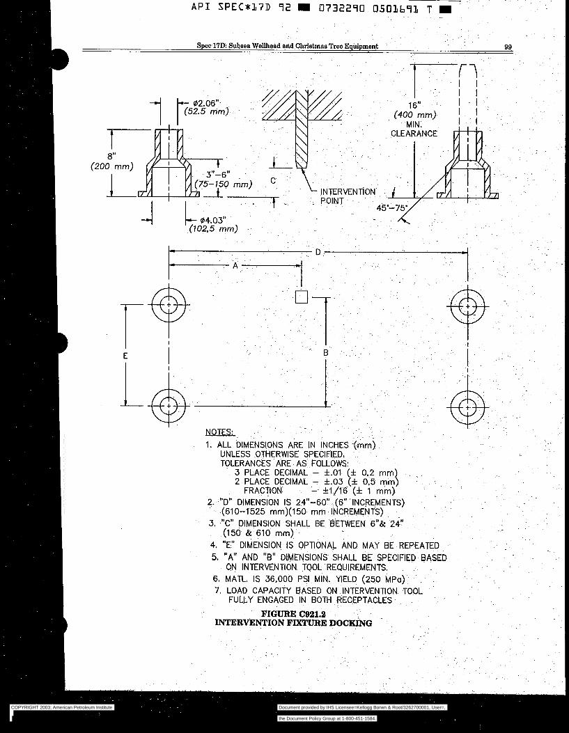
COPYRIGHT 2003; American Petroleum Institute
Document provided by IHS Licensee=Kellogg Borwn & Root/3262700001, User=, 09/10/2003 07:10:01 MDT Questions or comments about this message: please callthe Document Policy Group at 1-800-451-1584.
--`,,,``,```,`,`,``,`,,``,`,,`-`-`,,`,,`,`,,`---
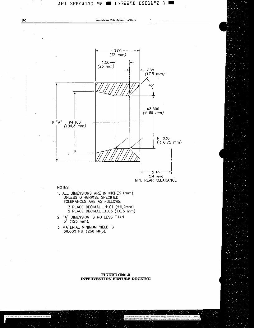
0 "A" 04.1 06 (104,3 mm)
-
L c 2.13 - I
(54 mm) MIN. REAR CLEARANCE
I
NOTES:
1. ALL DIMENSIONS ARE IN INCHES (mm) UNLESS OTHERWSE SPECIFIED. TOLERANCES ARE AS FOLLOWS:
3 PLACE DECIMAL .... 4.01 (f0,2mm) 2 PLACE DECIMAL ... f.03 (f0,5 mm)
2. "A" DIMENSION IS NO LESS THAN 5" (125 mm).
3. MATERIAL MINIMUM YIELD IS 36,000 PSI (250 MPa).
FIGURE C921.3 INTERVENTION FIXTURE DOCKING
COPYRIGHT 2003; American Petroleum Institute
Document provided by IHS Licensee=Kellogg Borwn & Root/3262700001, User=, 09/10/2003 07:10:01 MDT Questions or comments about this message: please callthe Document Policy Group at 1-800-451-1584.
--`,,,``,```,`,`,``,`,,``,`,,`-`-`,,`,,`,`,,`---
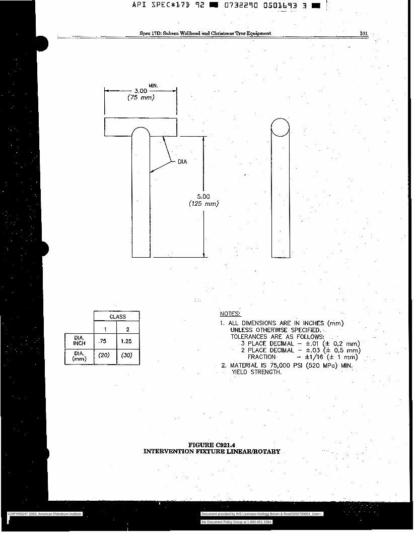
~ -~ A P I SPEC*l,7D 9 2 m 0732290 0501693 3 m ?
Spec 17D: Subsea Wellhead and.Christmas Tree Equipment 101
I l f
CLASS
INCH
NOTES:
1. ALL DIMENSIONS ARE IN INCHES (mm) UNLESS OTHERWISE SPECIFIED. - .
TOLERANCES ARE AS FOLLOWS: 3 PLACE DECIMAL - *.O1 (* 0,2 mm) 2 PLACE DECIMAL - *.O3 (* 0,5 mm)
FRACTION- - f1/16 (* 1 mm) 2. MATERIAL IS 75,000 PSI (520 MPa) MIN.
YIELD STRENGTH.
FIGURE (321.4 INTERVENTION FIXTURE LINEAlUROTARY
COPYRIGHT 2003; American Petroleum Institute
Document provided by IHS Licensee=Kellogg Borwn & Root/3262700001, User=, 09/10/2003 07:10:01 MDT Questions or comments about this message: please callthe Document Policy Group at 1-800-451-1584.
--`,,,``,```,`,`,``,`,,``,`,,`-`-`,,`,,`,`,,`---
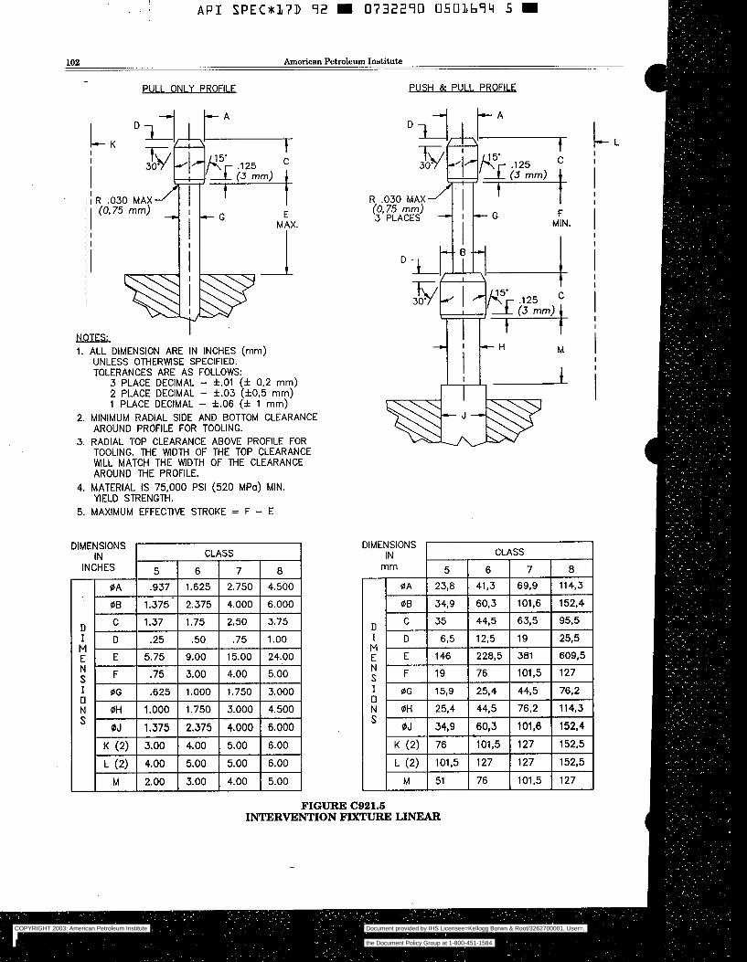
102 American Petroleum Institute
- Pul I ON1 Y PROFILE
' d NOTES:
i 1"
1. ALL DIMENSION ARE IN INCHES (mm) UNLESS OTHERWISE SPECIFIED. TOLERANCES ARE AS FOLLOWS:
3 PLACE DECIMAL - f .01 (f 0,2 mm) 2 PLACE DECIMAL - f.03 ( f0 ,5 mm) 1 PLACE DECIMAL - f.06 (f 1 mm)
2. MINIMUM RADIAL SIDE AND BOTTOM CLEARANCE AROUND PROFILE FOR TOOLING.
3. RADIAL TOP CLEARANCE ABOVE PROFILE FOR TOOLING. THE WIDTH OF THE TOP CLEARANCE WlLL MATCH THE WlDTH OF THE CLEARANCE AROUND THE PROFILE.
YIELD STRENGTH. 4. MATERIAL IS 75,000 PSI (520 MPo) MIN.
5. MAXIMUM EFFECTIVE STROKE = F - E
DIMENSIONS IN
INCHES
PUSH & PU1 I PROFI1 F
"/ L A D
R .O30 MAX (0.75 mm) 3 PLACES
i --H M
1 2
DIMENSIONS I I
0A 23,8
I M E N S
O I OG 15,s
N OH 25,4
CL
6 41,3
60.3 44,5
12.5
228,5
76 25,4
44.5
60,3 101,5
127
76
c-
I+ L (2) 101,5
,SS
7 8
69.9 114,3
101,6 152.4
63,5 95,5
19 25,5
381 609,5
101,5 127
44,5 76,2
76.2 114,3
101,6 152,4 127 1 5 2 3
127 152,5
101,5 127
FIGURE C921.6 INTERVENTION FMTURE LINEAR
COPYRIGHT 2003; American Petroleum Institute
Document provided by IHS Licensee=Kellogg Borwn & Root/3262700001, User=, 09/10/2003 07:10:01 MDT Questions or comments about this message: please callthe Document Policy Group at 1-800-451-1584.
--`,,,``,```,`,`,``,`,,``,`,,`-`-`,,`,,`,`,,`---
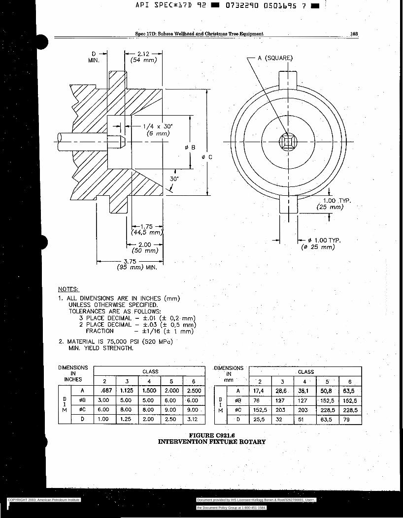
Spec 17D: Subsea Wellhead &d Christmas Tree Equipment 103
b 1 . 7 5 (44,s mm
(50 mm) - 2.00 I' I
~- 3.75 -4 (95 mm) MIN.
NOTES:
1. ALL DIMENSIONS ARE IN INCHES (mm) UNLESS OTHERWSE SPECIFIED. TOLERANCES ARE AS FOLLOWS:
3 PLACE DECIMAL - f.01 (f 0,2 mm) 2 PLACE DECIMAL - f.03 (* 0,5 mm)
FRACTION - f1/16 (?c 1 mm>
2. MATERIAL IS 75,000 PSI (520 MPa) MIN. YIELD STRENGTH.
y A (SQUARE) I
1.00 -TYP.
7 (25 mm)
- Ø 1.00 TYP. (0 25 mm)
FIGURE C921.6 INTERVENTION FIXTURE ROTARY
COPYRIGHT 2003; American Petroleum Institute
Document provided by IHS Licensee=Kellogg Borwn & Root/3262700001, User=, 09/10/2003 07:10:01 MDT Questions or comments about this message: please callthe Document Policy Group at 1-800-451-1584.
--`,,,``,```,`,`,``,`,,``,`,,`-`-`,,`,,`,`,,`---
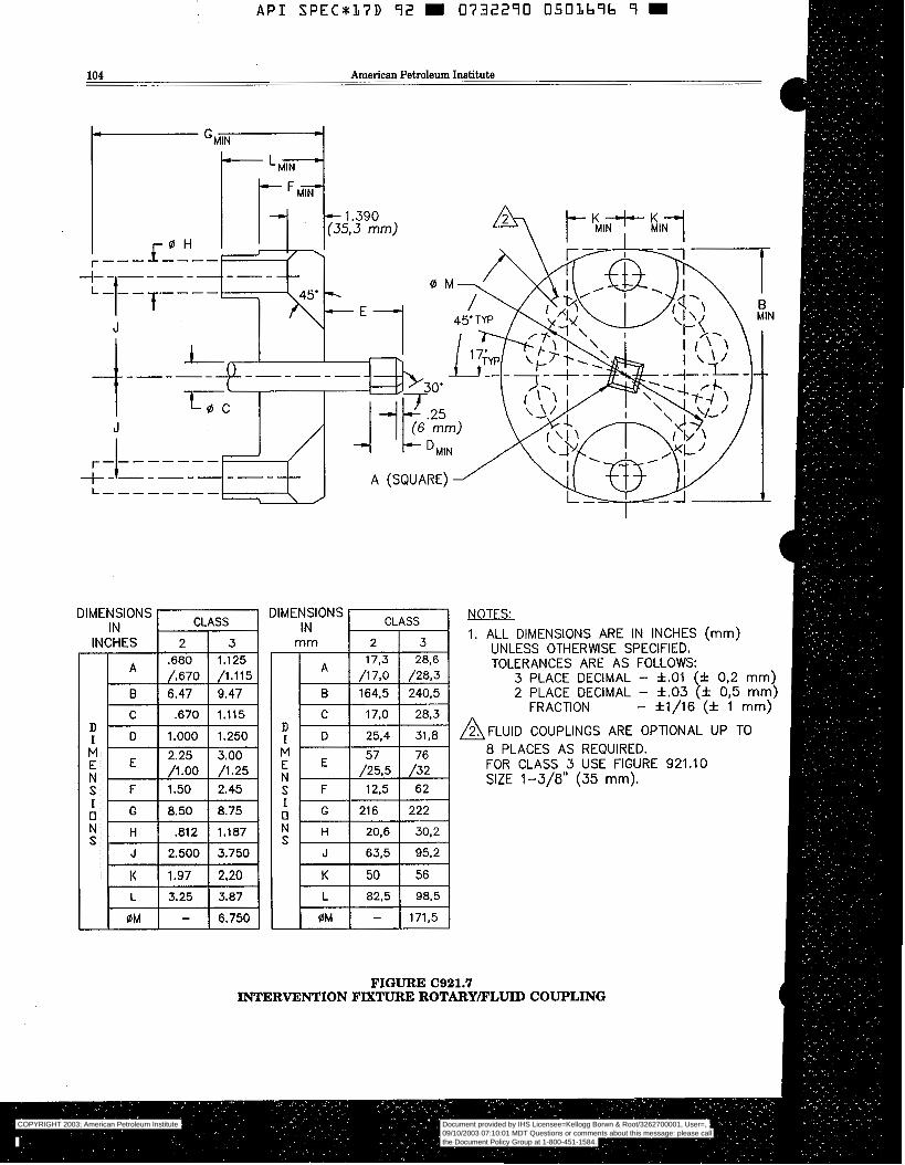
A P I S P E C 8 1 7 D 92 W 0732290 0 5 0 3 6 9 b 9 W
104 American Petroleum Institute
- 1.390 (353 mm)
D I M E N S I O N S
DIMENSIONS -1 DIMENSIONS NOTFS: IN 1. ALL DIMENSIONS ARE IN INCHES (mm)
UNLESS OTHERWISE SPECIFIED. TOLERANCES ARE AS FOLLOWS:
3 PLACE DECIMAL - f.01 (f 0,2 mm) 2 PLACE DECIMAL - f.03 (* 0,5 mm:
FRACTION - *1/16 (* 1 mm)
A F L U l D COUPLINGS ARE OPTIONAL UP TO 8 PLACES AS REQUIRED. FOR CLASS 3 USE FIGURE 921.10 SIZE 1-3/8" (35 mm).
I I
0M I - I 6.750 1
A G 216 N H S 20,6 30,2
J 63,5 95,2
222
FIGURE (2921.7 INTERVENTION FIXTURE ROTARY/FLUID COUPLING
COPYRIGHT 2003; American Petroleum Institute
Document provided by IHS Licensee=Kellogg Borwn & Root/3262700001, User=, 09/10/2003 07:10:01 MDT Questions or comments about this message: please callthe Document Policy Group at 1-800-451-1584.
--`,,,``,```,`,`,``,`,,``,`,,`-`-`,,`,,`,`,,`---
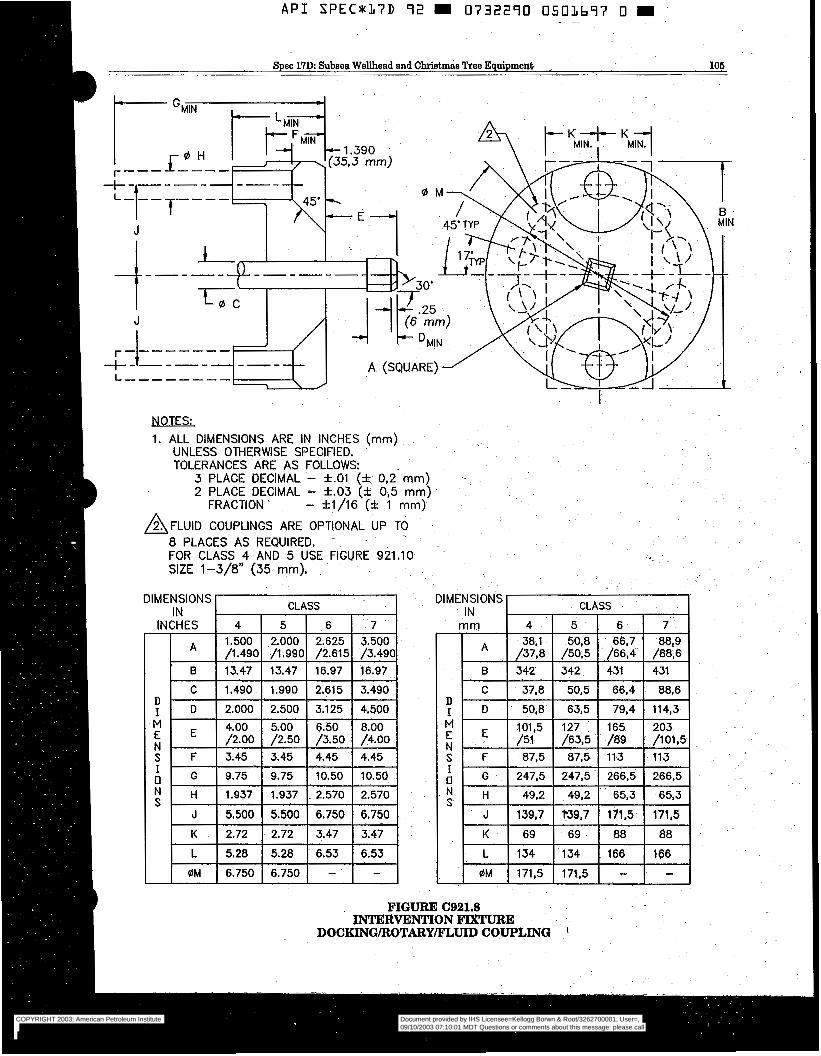
A P I S P E C x 1 7 D 92 m 0732290 0503697 O m i 1
Spec 17D Subaea Wellhead and Christmas Tree Equipment ~ 106
A
I
NOTES:
1. ALL DIMENSIONS ARE IN INCHES (mm) UNLESS OTHERWlSE SPECIFIED. TOLERANCES ARE AS FOLLOWS
3 PLACE DECIMAL - *.o1 (* 0,2- mm) 2 PLACE DECIMAL - *.O3 (f 0,5 mm)
FRACTION ’ - f1/16 (‘t 1 mm) h
A F L U I D COUPLINGS ARE OPTIONAL UP TO 8 PLACES AS REQUIRED. FOR CLASS 4 AND 5 USE FIGURE 921.10 SIZE 1-3/8” (35 mm),
DIMENSIONS IN
INCHES
A
B
C
; D
A - G
M E E N S F
N H S
J
K
L
0M
r CLASS
1.490 1.990 2.615 3.490 2.000 2.500 3.125 4.500 a /2.00 /2.50 /3.50 /4.00
I
5.28 I 5.28 I 6.53 I 6.53 6.750 6.750 - -
DIMENSIONS I I
IN mm I 4 7 /37.8
I B I 342
T k m E N
N S
139,7
OM 171,5
CLASS
342 I 431 I 4i:,6 I 50,5 66,4
FIGURE C921.8 INTERVENTION FIXTURE
DOCKING/ROTARY/J?LIJID COUPLING I
COPYRIGHT 2003; American Petroleum Institute
Document provided by IHS Licensee=Kellogg Borwn & Root/3262700001, User=, 09/10/2003 07:10:01 MDT Questions or comments about this message: please callthe Document Policy Group at 1-800-451-1584.
--`,,,``,```,`,`,``,`,,``,`,,`-`-`,,`,,`,`,,`---
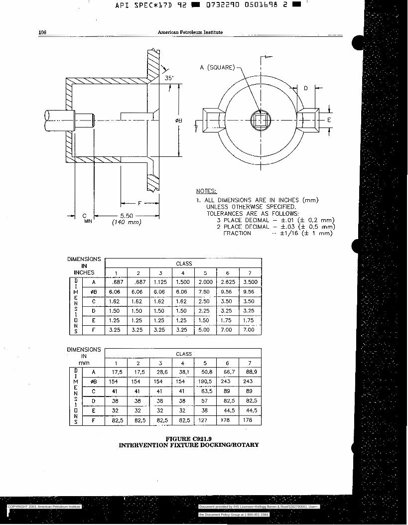
API S P E C U I J D 92 m 0 7 3 2 ~ 0 O S O I M B 2 m
106 American Petroleum Institute
I \\\\u
C k- 5.50 -4 MIN (740 mm)
r A (SQUARE) 7
NOTES:
1. ALL DIMENSIONS ARE IN INCHES (mm) UNLESS OTHERWSE SPECIFIED. TOLERANCES ARE AS FOLLOWS:
3 PLACE DECIMAL - *.O1 (* 0,2 mm) 2 PLACE DECIMAL - f.03 (* 0.5 mm)
FRACTION - f1/16 (6 1 mm)
DIMENSIONS IN CLASS
INCHES 1 1 2 1 3 1 4 5 6 7 ,687 ,687 1.125 1.500 2.000 2.625 3.500
M ØB 6.06 6.06 6.06 6.06 7.50 9.56 9.56 I M I C ¡ 1.62 ¡ 1.62 ¡ 1.62 ¡ 1.62 ¡ 2.50 ¡ 3.50 ¡ 3.50 I E
D 1.50 1.50 1.50 1.50 2.25 3.25 3.25 I O E 1.25 1.25 1.25 1.25 1.50 1.75 1.75 N S F 3.25 3.25 3.25 3.25 5.00 7.00 7.00
DIMENSIONS IN CLASS
mm 1 2 1 3 1 4 1 5 1 6 1 7 D I A I 17.5 I 17.5 I 28,6 I 38.1 I 50,8 I 66.7 88.9
FIGURE C921.9 INTERVENTION FIXTURE DOCKINGlROTARY
COPYRIGHT 2003; American Petroleum Institute
Document provided by IHS Licensee=Kellogg Borwn & Root/3262700001, User=, 09/10/2003 07:10:01 MDT Questions or comments about this message: please callthe Document Policy Group at 1-800-451-1584.
--`,,,``,```,`,`,``,`,,``,`,,`-`-`,,`,,`,`,,`---
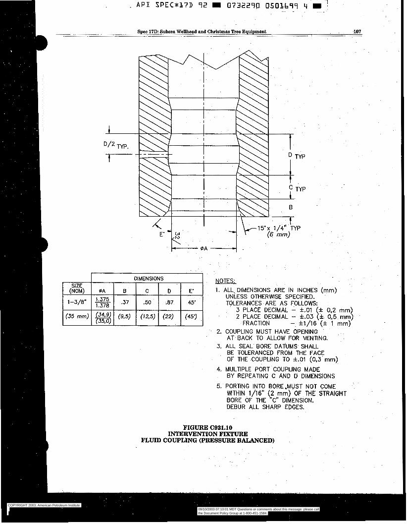
Spec 17D Subsea Wellhead and Christmas Tree Equipment 107
DIMENSIONS SIZE
(NOM) OA B C D E‘
.50 .87 45’ 1-3/8” - 1.375 1.378
(35 mm) ( 9 3 ) (12,s) (22) (457
NOTES:
1. -ALL% DIMENSIONS ARE IN INCHES (mm) UNLESS OTHERWISE SPECIFIED. TOLERANCES ARE AS FOLLOWS:
3 PLACE DECIMAL - *.O1 (* 0,2 mm) 2 PLACE DECIMAL - f.03 (* 0,5 mm)
FRACTION - *1/16 (* 1 mm) 2. COUPLING MUST HAVE OPENING
3, ALL SEAL BORE DATUMS SHALL AT BACK TO ALLOW FOR VENTING.
BE TOLERANCED FROM THE FACE OF THE -COUPLING TO f.O1 (0.3 mm)
BY REPEATING C AND D DIMENSIONS
5. PORTING INTO BORE,MUST NOT COME
4. MULTlPLE PORT COUPLING MADE
MTHIN 1/16” (2 mm) OF THE STRAIGHT BORE OF THE ”C” DIMENSION. DEBUR ALL SHARP EDGES.
FIGURE C921.10 INTERVENTION FIXTURE
FLUID COUPLING (PRESSURE BALANCED)
COPYRIGHT 2003; American Petroleum Institute
Document provided by IHS Licensee=Kellogg Borwn & Root/3262700001, User=, 09/10/2003 07:10:01 MDT Questions or comments about this message: please callthe Document Policy Group at 1-800-451-1584.
--`,,,``,```,`,`,``,`,,``,`,,`-`-`,,`,,`,`,,`---
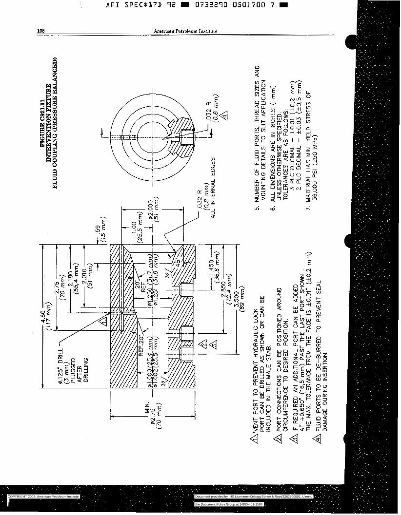
A P I SPECa17D 9 2 m 0732290 0501700 7 m
108 American Petroleum Institute
o f
uj
I-+ Z E w o > a
A
E E
m a v, W J a
n n W
2 z
a W v, l- m W > W LT a
Q Q 4
COPYRIGHT 2003; American Petroleum Institute
Document provided by IHS Licensee=Kellogg Borwn & Root/3262700001, User=, 09/10/2003 07:10:01 MDT Questions or comments about this message: please callthe Document Policy Group at 1-800-451-1584.
--`,,,``,```,`,`,``,`,,``,`,,`-`-`,,`,,`,`,,`---
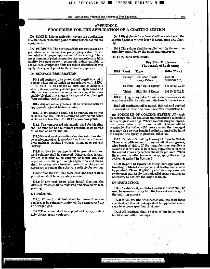
A P I SPECUL7D 92 m .O732290 0501701 9 W I ~~ ~ ~~ ~~~~ _.
Spec 17D: Subsea Wellhead and Christmas Tree Equipment 109
APPENDIX D PROCEDURE FOR THE APPLICATÏON OF A COATING SYSTEM
D l SCOPE. This specification covers the application of a standard protective paint coating system for subaea~ equipment.
D2 PURPOSE. The purpose of this protective coating procedure is to ensure the proper preparation of the material and proper application of the coating. There are a number of paint companies that manufacture high quality two part epoxy - polyamide paints suitable to coat subsea equipment. "his procedure describes how to apply this type of paint to the subsea equipment.
D3 SURFACE PREPARATION.
D3.1 All surfaces to be coated shall be grit blasted to a near white metal finish in accordance with SSPC- SPlO (Sa 2 l/2) to remove all rust, and to achieve a sharp, dense, anchor pattern profile. Open bores and other access to operable components should be thor- oughly blocked in a manner to prevent.shot blast grit from entering tree internals.
D3.2 Any oil and/or grease shall be removedwith an appropriate solvent before priming.
D3.3 Blast cleaning shall not be carried out on wet surfaces, nor shall blast cleaning be carried out when surfaces are less than 5 7 (3°C) above dew point.
D3.4 The compressed air supply used for blasting shall be supplied at a minimum pressure of 70 psi (O$ MPa) free of water and oil.
D3.5 No acid washes or other cleaning solutions shall be used on metal surfaces after they have been blasted, This includes inhibited washes intended to prevent rusting.
D3.6 Surface laminations shall be ground out, and weld splatter shall be removed. Other surface irregu- larities including rough capping, undercut and slag together with sharp or rough edges, fins and burrs, shall be power wire brushed, ground or chipped as necessary to render the substrate suitable for coating.
D3.7 Areas that will not be painted and that require protection shall be adequately masked.
D3.8 If any rust forms after initial blasting, the rusted surfaces shall be reblasted and cleaned prior to priming.
D4 PRIMING.
D4.1 All sand and dust shall be blown from the surfaces to be primed with dry, oil-free compressed air or nitrogen gas.
D4.2 The primer shall be applied with spray, prefer- ably airless spray equipment.
D4.3 Blast cleaned surfaces shall be coated with the specified primer within four (4) hours after grit blast- ing.
D4.4 The primer shall be applied within the rélative humidity specified by the paint manufacturer,
DS COATING SYSTEMS,
Dry Film Thickness Thousands of Inch (mm)
DS.l Coat Type (MinJMaX.)
Primer Red Lead Oxide 2.5/3.0 Epoxy Prime - (0,065/0,075)
Second High Solid Epoxy 5/6 (0,13/0,15)-
T&rd High Solid Epoxy 5/6 (0,13/0,15)
DS.2 Drying times between coats shall be strictly in accordance with the pain€ manufacturer's instructiöns.
DS;3 All coatings shall be mixed, thinned and applied in accordance with the manufacturer's instructions.
D6 TOUCH OF COATING SYSTEM. All touch up coatings shall be the-same manufacturer's materials as the original coatings. Where sandblasting is imprac- tical, power wire brush to remove all oxidation will be acceptable. Six inches (150 mm) around the damaged area may also be wire brushed or lightly sanded by hand to roughen the epoxy to promote adhesion.
D6.1 Repair of Coating Damage Down to Metal. Clean area with solvent to remove all oil and grease, wire brush if shiny. If the manufacturer supplies a solvent that will assist in repair, apply the solvent to the coated areas adjacent to the damaged area. When the aqjacent coating becomes tacky, apply the coating system described in Section 5.
D6.2 Repair of Epoxy Coating Damage Not Ex- tending to Metal, Sandpaper and feather out area to be repaired. Clean off with dry oil-free compressed air or nitrogen gas. Apply the high solid epoxy coatings as necessary to achieve the original finish.
D7 INSPECTION.
D7.1 A calibrated paint film thickness device shall be used to measure the dry film thickness at each stage of the painting process.
D7.2 When dry film tl&lmesses are less than those specified, additional coatings shall be applied as neces- sary to achieve specified thickness.
D7.3 All coatings shall be free of pin holes, voids, bubbles, and other holidays.
COPYRIGHT 2003; American Petroleum Institute
Document provided by IHS Licensee=Kellogg Borwn & Root/3262700001, User=, 09/10/2003 07:10:01 MDT Questions or comments about this message: please callthe Document Policy Group at 1-800-451-1584.
--`,,,``,```,`,`,``,`,,``,`,,`-`-`,,`,,`,`,,`---
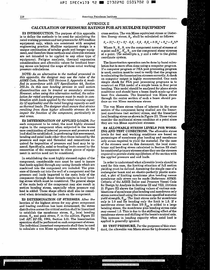
A P I SPECU17D 9 2 m 0732290 0 5 0 1 7 0 2 O 6
110 American Petroleum Institute
APPENDIX E CALCULATION OF PRESSURE: RATINGS FORAPI MUDLINE EQUIPMENT
E l INTRODUCTION. The purpose of this appendix is to define the methods to be. used for calculating the rated working pressure and test pressure for API mudline equipment only, which are consistent with accepted engineering practice. Mudline equipment design is a unique combination of tubular goods and hanger equip- ment, and therefore these methods and allowable stresses are not intended to be applied to any other type of equipment. Fatigue analysis, thermal expansion considerations and allowable values for localized bear- ing stress are beyond the scope of these rated working pressure calculations.
NOTE: As an alternative to the method presented in this appendix, the designer may use the rules of the ASME Code, Section VIII Division 2, Appendix 4, modi- fied in accordance with API Specification SA, Section
. 3 0 3 . 3 ~ . In this case bending stresses in wall section discontinuities can be treated as secondary stresses. However, when using this alternative method, the calcu- lation for rated working pressure must be made in com- bination with loads applied by the rated running capac- ity (if applicable) and the rated hanging capacity as well as thermal loads. The designer shall ensure that strains resulting from these higher allowable stresses do not impair the function of the component, particularly in seal areas.
E2 DETERMINATION OF APPLIED LOADS. For each component to be rated, the most highly stressed region in the component when subjected to the worse case combination of internal pressure and pressure end load shall be established. In performing this assessment, bending and axial loads other than those induced by the pressure end caps and threaded end connections re- quired for imposition of pressure end load may be ig- nored. Specifically, axial or bending loads caused by the connection of the component to other pieces of equip- ment in service need not be considered.
In establishing the most highly stressed region of the component, considerable care must be used to insure that loads applied through any casing threads which are machined into the component are included. The pres- ence of threads cut into the wall of a component and the pressure end loads imparted to the main body of the component through these threads results in local bend- ing stress which must be considered. The general shape of the main body of the component may also result in section bending stress, especially when pressure end load is added. These shape effects shall also be consid- ered when determining the loads on the component.
E3 DETERMINATION OF STRESSES. After the location of the highest stress for any given component and loading condition has been determined, the stress distribution across the critical section shall be linearized to establish the membrane stress, Sm, local bending stress, S,,, and peak stress, F, in the section, Figure E l (ref: API RP-PR, 1984, Section 3.5). The linearization operation shall be performed on each component of stress. The individual linearized components shall then be used to calculate a von Mises equivalent stress through the
cross section. The von Mises equivalent stress or Distor- tion Energy stress, Se, shall be calculated as follows:
se = [S: + S,' + S:- spy - sp, - sp, + 3 CS,' + S=: + S,V
Where S , Sy, S. are the component normal stresses at a point and S , Sxz, S,. are the component shear stresses at a point. Tre subscripts x, y and z refer to the global coordinate system.
The linearization operation can be done by hand calcu- lation but is more often done using a computer program. If a computer program or FEA post processing program is used, caution must be used to verify that the program is calculating the linearization stresses correctly. A check on computer output is highly recommended. One such simple check for FEA post processing programs is to construct an FEA model of a simple beam in four point bending. This model should be analyzed for plane strain conditions and should have a beam depth made up of at least five elements. The linearized von Mises stress through the center section of such a beam should pro- duce no von Mises membrane stress.
The von Mises stress values of interest in the cross section of the component being studied are the linear- ized membrane (net section) stress, and the linearized local bending stress as shown in Figure El. These values consider the multiaxial stress condition at a point since they are von Mises equivalent stresses.
ING AND TEST CONDITIONS. The allowable stress levels for test and working conditions are based on percentages of membrane plus bending and membrane only stress required to yield the material. For the case of the stresses used in this document, the local mem- brane and bending stress calculated in Section E3 shall be considered primary stresses since they are the stresses required to provide static equilibrium of the section with the applied pressure and end loads.
In order to understand what allowable levels should be used for this case, the limiting situation of full section yielding must be defined. Assuming the simple case of a rectangular beam and an elastic-perfectly plastic mate- rial, a plot of limiting membrane plus bending versus membrane only stress can be made (Reference: ASME: Criteria of the ASME Boiler and Pressure Vessel Code for Design by Analysis in Sections III and VIII, Division 2). Figure E2 shows the limiting values of various com- binations of membrane plus bending and membrane only stress normalized using the minimum specified material yield strength, S d. The limit stress ratio for membrane only is 1.0 and b r bending only the limit is 1.5. If a membrane stress less than W3 Syla is added to a large bending stress, the membrane plus bending stress ratio may exceed 1.5. This is due to the stiffening effect of the membrane stress and shifting of the beam's neutral axis. This increase in bending capacity when axial load is applied is generally ignored.
ES TEST PRESSURE. For the purposes of this stan- dard, the allowable von Mises stress for hydrostatic test
E4 ALLOWABLE STRESS LEVELS FOR WORK
COPYRIGHT 2003; American Petroleum Institute
Document provided by IHS Licensee=Kellogg Borwn & Root/3262700001, User=, 09/10/2003 07:10:01 MDT Questions or comments about this message: please callthe Document Policy Group at 1-800-451-1584.
--`,,,``,```,`,`,``,`,,``,`,,`-`-`,,`,,`,`,,`---
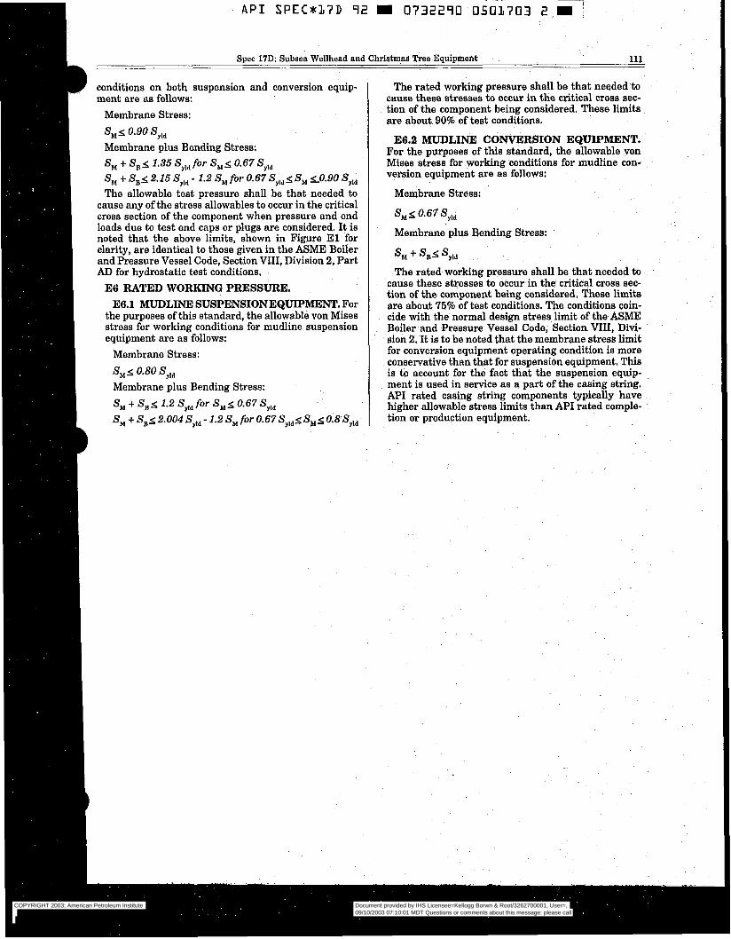
I
' A P I SPEC*17D 92 9 0732290 0501703 2 m
Spec 17D: Subsea Wellhead and Christmas Tree Equipment 111
conditions on both suspension anä conversion equìp- ment are as follows:
Membrane Stress: < Omgo
Membrane plus Bending Stress: S, + SB4 1.35 Syld for Shi< 0.67 S,,, S, + SBs 2.15 Syld - 1.2 S, for 0.67 Syld< S, 20.90 Syld The allowable test pressure shall be that needed to
cause any of the stress allowables to occur in the critical cross section of the component when pressure and end loads due to test end caps or plugs are considered. It is noted that the above limits, shown in Figure E l for clarity, are identical to those given in the ASME Boiler and Pressure Vessel Code, Section VIII, Division 2, Part AD for hydrostatic test conditions.
E6 RATED WORKING PRESSURE. E6.1 MUDLINE SUSPENSIONEQUIPIMENT. For
the purposes of this standard, the allowable von Mises stress for working conditions for mudline suspension equipment are as follows:
Membrane Stress:
< 0.80 Membrane plus Bending Stress: S, + S, 1.2 Syld for S, 0.67 S,,, S,+S,~2.004S,,,-1.2S,for0.67Syld~S,~0.8Syld
The rated working pressure shall be that needed to cause these stresses to occur in the critical cross sec- tion of the component being considered. These limits are about 90% of test conditions.
E6.2 MUDLINE CONVERSION EQUIPMENT. For the purposes of this standard, the allowable von Mises stress for working conditions for mudline con- version equipment are as follows:
Membrane Stress:
S, < 0.67 Syld
Membrane plus Bending Stress:
'M ' 'yld
The rated working pressure shall be that needed to cause these stresses to occur in the critical cross sec- tion of the component being considered, These limits are about 75% of test conditions. The conditions coin- cide with the normal design stress limit of the ASME Boiler and Pressure Vessel Code, Section VIII, Divi- sion 2. It is to be noted that the membrane stress limit for conversion equipment operating condition is more conservative than that for suspension equipment. This is to account for the fact that the suspension equip- ment is used in servìce as a part of the casing string. API rated casing string components typically have higher allowable stress limits than API rated comple- tion or production equipment.
COPYRIGHT 2003; American Petroleum Institute
Document provided by IHS Licensee=Kellogg Borwn & Root/3262700001, User=, 09/10/2003 07:10:01 MDT Questions or comments about this message: please callthe Document Policy Group at 1-800-451-1584.
--`,,,``,```,`,`,``,`,,``,`,,`-`-`,,`,,`,`,,`---
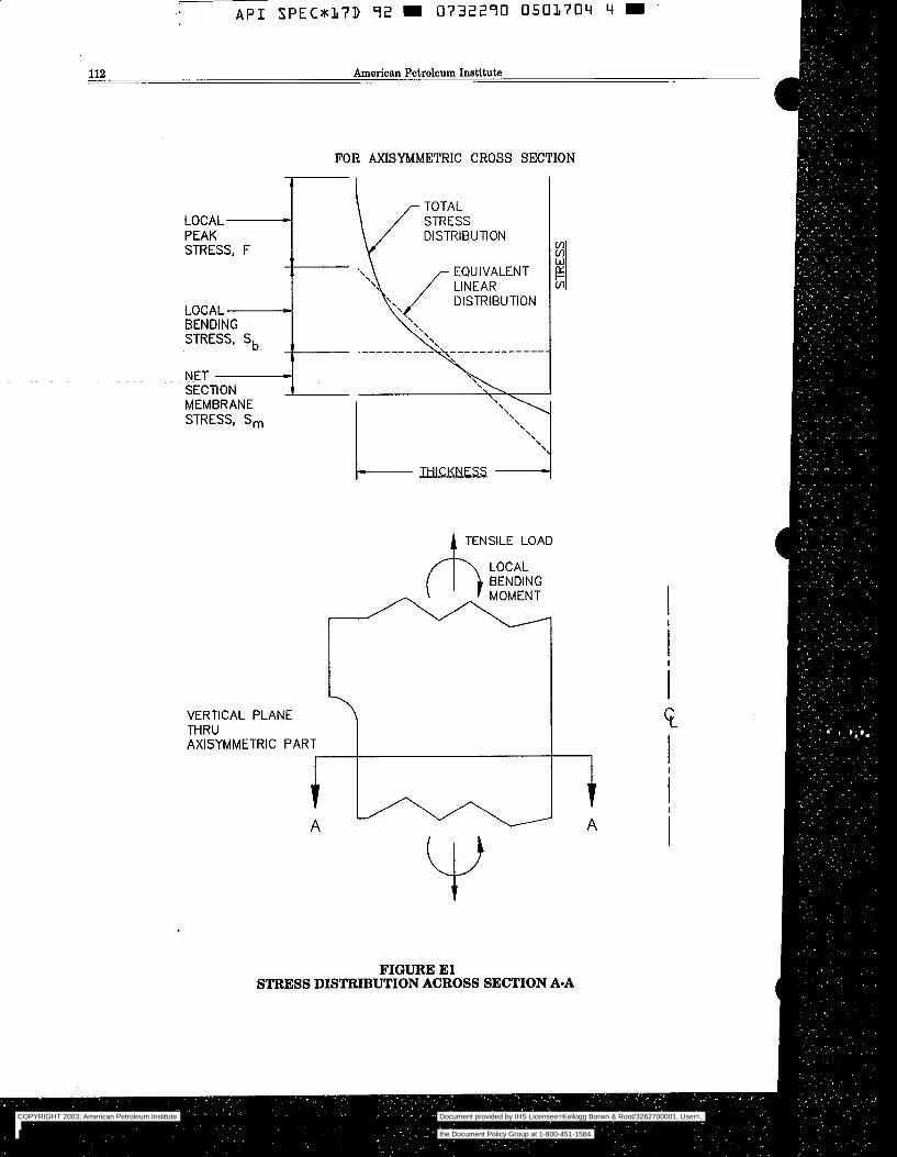
FOR AXISYMMETRIC CROSS
F I SECTION
LOCAL L
PEAK STRESS, F
II
II
LOCAL 21
BENDING STRESS, S,, !I
NET - SECTION 1 MEMBRANE STRESS, S,
/I
TENSILE LOAD
LOCAL BENDING MOMENT
i VERTICAL PLANE THRU AXISYMMETRIC PART
A u Y
I i i
i i
G I
FIGURE E l STRESS DISTRIBUTION ACROSS SECTION A-A
COPYRIGHT 2003; American Petroleum Institute
Document provided by IHS Licensee=Kellogg Borwn & Root/3262700001, User=, 09/10/2003 07:10:01 MDT Questions or comments about this message: please callthe Document Policy Group at 1-800-451-1584.
--`,,,``,```,`,`,``,`,,``,`,,`-`-`,,`,,`,`,,`---
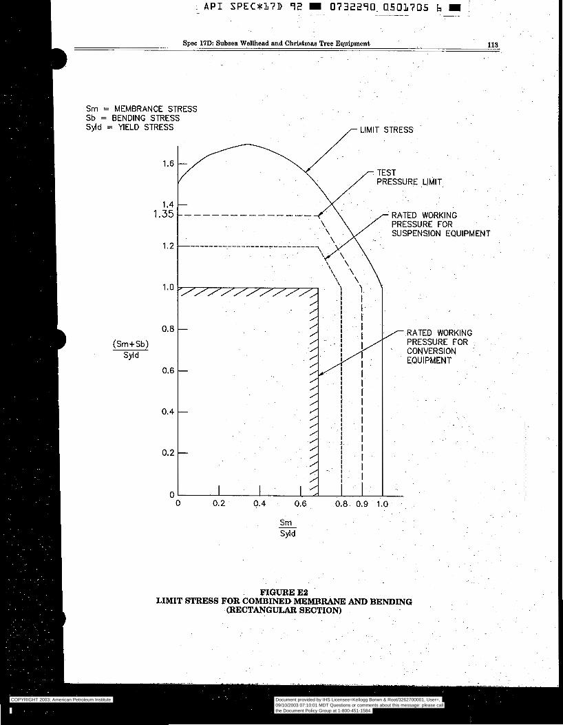
. A P I SPECSK17D 72 0732290. 0503705 b i ~ .~ ~ - . ~~
- ~~~~ ~- ~ -~
Spec 17D: Subsea Wellhead and Christmas Tree Equipment 113
Sm = MEMBRANCE STRESS Sb = BENDING STRESS S$d = YIELD STRESS
1.6
1.4 1.35
1.2
1.0
O. 8
(Sm+Sb) Syld
O. 6
O. 4
o. 2
O L
/- STRESS
""_"""_" - RATED WORKING PRESSURE FOR SUSPENSION EQUIPMENT
\
\
Ø
O o. 2 0.4 0.6 0.8 0.9 1.0 -
Sm - Syld
FIGURE E2 LIMIT STRESS FOR COMBINED MEMBRANE AND BENDING
(RECTANGULAR SECTION)
RATED WORKING PRESSURE FOR CONVERSION .
EQUIPMENT
COPYRIGHT 2003; American Petroleum Institute
Document provided by IHS Licensee=Kellogg Borwn & Root/3262700001, User=, 09/10/2003 07:10:01 MDT Questions or comments about this message: please callthe Document Policy Group at 1-800-451-1584.
--`,,,``,```,`,`,``,`,,``,`,,`-`-`,,`,,`,`,,`---
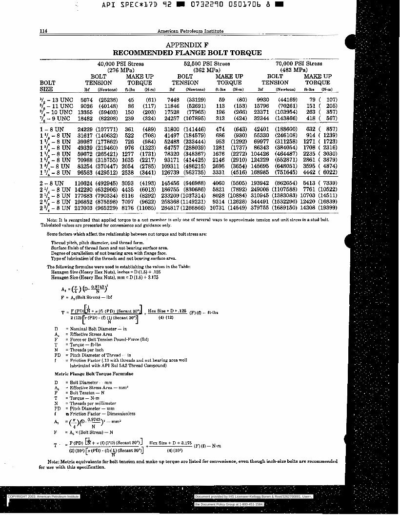
~
A P I SPEC*KL7D 92 0732290 0503706 B
114 American Petroleum Insti tute
APPENDIX F RECOMMENDED FLANGE BOLT TORQUE
40,000 PSI Stress 52,500 PSI Stress 70,000 PSI Stress
BOLT MAKE UP BOLT MAKEUP BOLT MAKEUP BOLT TENSION TORQUE TENSION TORQUE TENSION TORQUE SIZE lbf (Newtons) fi-lbs (N-m) lbf (Newtons) fi-lbs (N-m) lbf (Newtons) b l b s (N-m)
(- 11 UNC 9026 (40148) 86 (117) 11846 (52691) 113 (153) 15796 (70261) 151 ( 205) 3/4- 10 UNC 13355 (59403) 150 (203) 17528 (77965) 196 (266) 23371 (103954) 263 ( 357)
- 9 UNC 18482 (82208) 239 (324) 24257 (107895) 313 (424) 32344 (143866) 418 ( 567)
1 - 8 UN 24229 (107771) 361 (489) 31800 (141446) 474 (643) 42401 (188600) 632 ( 857) 1 - 8 UN 31617 (140632) 522 (708) 41497 (184579) 686 (930) 55330 (246108) 914 ( 1239) 1 V 4 - 8 UN 39987 (177862) 726 (984) 52483 (233444) 953 (1292) 69977 (311258) 1271 ( 1723) 13/8 - 8 UN 49339 (219460) 976 (1323) 64757 (288039) 1281 (1737) 86343 (384054) 1708 ( 2316)
16( - 8 UN 70988 (315755) 1635 (2217) 93171 (414425) 2146 (2910) 124229 (552871) 2861 ( 3879)
(276 MPa) (362 MPa) (483 MPa)
V - 13 UNC 5674 (25238) 45 (61) 7448 (33129) 59 (80) 9930 (44169) 79 ( 107)
1 '/ - 8 UN 59672 (265421) 1277 (1731) 78320 (348367) 1676 (2272) 104426 (464487) 2235 ( 3030)
1 3/4- 8 UN 83254 (370447) 2054 (2785) 109311 (486215) 2695 (3654) 145695 (648051) 3595 ( 4874) 17/8 - 8 UN 96563 (429512) 2538 (3441) 126739 (563735) 3331 (4516) 168985 (751645) 4442 ( 6022)
2 - 8 UN 110624 (492945) 3093 (4193) 145456 (646988) 4060 (5505) 193942 (862654) 5413 ( 7339) 2 1/4 - 8 UN 142290 (632906) 4435 (6013) 186755 (830686) 5821 (7892) 249008 (1107588) 7761 (10522) 2 '/ - 8 UN 177683 (790334) 6116 (8292) 233209 (1037314) 8028 (10884) 310945 (1383083) 10703 (14511)
2 3/4 - 8 UN 217003 (965229) 8176 (11085) 284817 (1266866) 10731 (14549) 379755 (1689150) 14308 (19399) 2 6( - 8 UN 196852 (875598) 7097 (9622) 258368 (1149221) 9314 (12628) 344491 (1532296) 12420 (16839)
Tabulated values are presented for convenience and guidance only. Note: It is recognized that applied torque to a nut member is only one of several ways to approximate tension and unit stress in a stud bolt.
Some factors which affect the relationship between nut torque and bolt stress are:
Thread pitch, pitch diameter, and thread form. Surface finish of thread faces and nut bearing surface area. Degree of parallelism of nut bearing area with flange face. Type of lubricationóf the threads and nut bearing surface area.
The following formulae were used in establishing the values in the Table: Hexagon Size (Heavy Hex Nuts), inches = D (1.5) + ,125 Hexagon Size (Heavy Hex Nuts), mm = D (1.5) t 3.175
F = &(Bolt Stress) - Ibf
T = F (PD)[h + fi (PD) (Secant 30.J + Hex Size + D + J25 (F)(D - ft-lbs 2 (12) (PD) - (f) u) (Secant 30") (4) (12)
N 1 A, = Effective Stress Area D = Nominal Bolt Diameter - in
F = Force or Bolt Tension Pound-Force (Ibo T = Torque - ft-lbs N = Threads per inch PD = Pitch Diameter of Thread - in f = Friction Factor (.13 with threads and nut bearing area well
lubricated with API Bu1 5A2 Thread Compound)
Metric Flange Bolt Torque Formulae
D = Bolt Diameter - mm
F = Bolt Tension - N T = Torque - N m N = Threads per millimeter
f Friction Factor - Dimensionless PD = Pitch Diameter - mm
= Effective Stress Area - mm'
COPYRIGHT 2003; American Petroleum Institute
Document provided by IHS Licensee=Kellogg Borwn & Root/3262700001, User=, 09/10/2003 07:10:01 MDT Questions or comments about this message: please callthe Document Policy Group at 1-800-451-1584.
--`,,,``,```,`,`,``,`,,``,`,,`-`-`,,`,,`,`,,`---
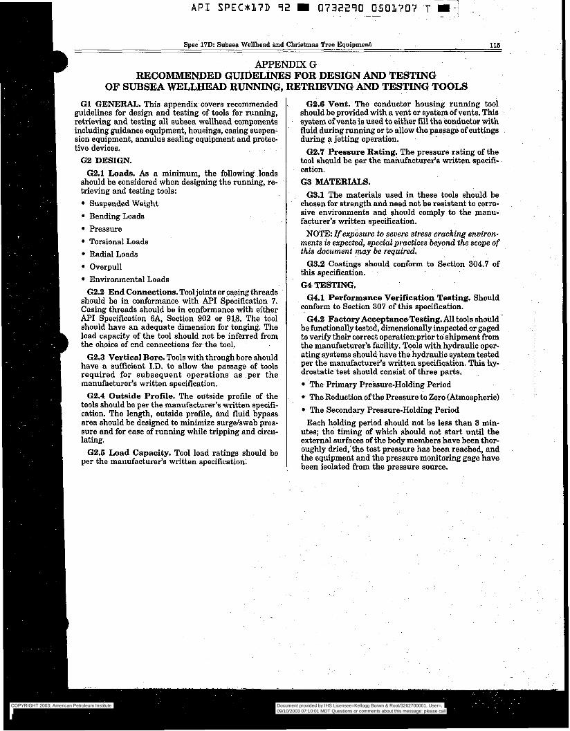
RECOMMENDED GUIDELINES FOR DESIGN AND TESTING OF SUBSEA WELLHEAD RUNNING, RETRIEVING AND TESTING TOOLS
G1 GENERAL. This appendix covers recommended guidelines for design and testing of tools for running, retrieving and testing all subsea wellhead components including guidance equipment, housings, casing suspen- sion equipment, annulus sealing equipment and protec- tive devices.
6 2 DESIGN. 62.1 Loads. As a minimum, the following loads
should be considered when designing the running, re- trieving and testing tools:
Suspended Weight Bending Loads Pressure Torsional Loads Radial Loads Overpull Environmental Loads
62.2 End Connections. Tool joints or casing threads should be in conformance with API Specification 7. Casing threads should be in conformance with either API Specification 6A, Section 902 or 91.8. The tool should have an adequate dimension for tonging. The load capacity of the tool should not be inferred from the choice of end connections for the tool.
62.3 Vertical Bore. Tools with through bore should have a sufficient I.D. t o allow the passage of tools required for subsequent operations as per the manufacturer’s written specification.
G2.4 Outside Profile. The outside profile of the tools should be per the manufacturer’s written specifi- cation. The length, outside profile, and fluid bypass area should be designed to minimize surgdswab pres- sure and for ease of running while tripping and circu- lating.
62.6 Load Capacity. Tool load ratings should be per the manufacturer’s written specification.
62.6 Vent. The conductor housing running tool should be provided with a vent or system of vents. This system of vents is used to either fill the conductor with fluid during running or to allow the passage of cuttings during a jetting operation.
62.7 Pressure Rating. The pressure rating of the tool should be per the manufacturer‘s written specifi- cation. 6 3 MATERIALS.
63.1 The materials used in these tools should be chosen for strength and need not be resistant to COITO- sive environments and should comply to the manu- facturer’s written specification.
NOTE: If exposure to severe stress cracking environ- ments is expected, specialpractices beyond the scope of this document may be required.
63.2 Coatings should conform to Section 304.7 of this specification. 6 4 TESTING.
conform to Section 307 of this specification.
be functionally tested, dimensionally inspected or gaged to verify their correct operationprior to shipment from the manufacturer’s facility. Tools with hydraulic oper- ating systems should have the hydraulic system tested per the manufacturer’s written Specification. This hy- drostatic test should cansist of three parts.
The Primary Pressure-Holding Period The Reduction of the Pressure to Zero (Atmospheric) The Secondary Pressure-Holding Period
Each holding period should not be less than 3 min- utes; the timing of which should not start until the external surfaces of the body members have been thor- oughly dried,‘the test pressure has been reached, and the equipment and the pressure monitoring gage have been isolated from the pressure source.
64.1 Performance Verification Testing. Should
64.2 Factory Acceptance Testing. All tools should .
COPYRIGHT 2003; American Petroleum Institute
Document provided by IHS Licensee=Kellogg Borwn & Root/3262700001, User=, 09/10/2003 07:10:01 MDT Questions or comments about this message: please callthe Document Policy Group at 1-800-451-1584.
--`,,,``,```,`,`,``,`,,``,`,,`-`-`,,`,,`,`,,`---
A P I SPECx17D 92 0732290 0501708 I I
COPYRIGHT 2003; American Petroleum Institute
Document provided by IHS Licensee=Kellogg Borwn & Root/3262700001, User=, 09/10/2003 07:10:01 MDT Questions or comments about this message: please callthe Document Policy Group at 1-800-451-1584.
--`,,,``,```,`,`,``,`,,``,`,,`-`-`,,`,,`,`,,`---
A P I S P E C * L 7 D 92 E 0732290 0503709 3
Order No. 81 1-07265
Additional copies available from AMERICAN PETROLEUM INSTITUTE Publications and Distribution Section 1220 L Street, NW - Washington, DC 20005 (202) 682-8375
COPYRIGHT 2003; American Petroleum Institute
Document provided by IHS Licensee=Kellogg Borwn & Root/3262700001, User=, 09/10/2003 07:10:01 MDT Questions or comments about this message: please callthe Document Policy Group at 1-800-451-1584.
--`,,,``,```,`,`,``,`,,``,`,,`-`-`,,`,,`,`,,`---