
SPECIFICATION FOR LINE & ERECTION - OPTCL Supply of tower structures for the transmission lines 23...
57
Tender notice no. - NIT/ OPTCL/ ODAFFP (1-R) (F)/03, Dt-07-11-.2014 VOL-II(TS) E12 - LINE & ERECTION PAGE 1 / 24 CHAPTER- E-12 SPECIFICATION FOR LINE & ERECTION
Transcript of SPECIFICATION FOR LINE & ERECTION - OPTCL Supply of tower structures for the transmission lines 23...
Tender notice no. - NIT/ OPTCL/ ODAFFP (1-R) (F)/03, Dt-07-11-.2014
VOL-II(TS) E12 - LINE & ERECTION PAGE 1 / 24
CHAPTER- E-12
SPECIFICATION
FOR
LINE & ERECTION
Tender notice no. - NIT/ OPTCL/ ODAFFP (1-R) (F)/03, Dt-07-11-.2014
VOL-II(TS) E12 - LINE & ERECTION PAGE 2 / 24
TABLE OF CONTENTS
OF TECHNICAL SPECIFICATION FOR CONSTRUCTION OF 11KV LINES
NO DESCRIPTION PAGE NO.
1.0 General 3
2.0 Survey 3
3.0 Check survey 5
4.0 Pole fixture and accessories 6 5.0 Stringing and Installation of Line with Conductors 7
6.0 Way-leave and tree cutting 11
7.0 Sub-soil investigation 12
8.0 Conductor 14
9.0 Erection work 15
10.0 Construction of foundation for tower , G.I(RS joist) poles and psc poles 15
TABLE OF CONTENTS OF
ALUMINIUM BINDING WIRE TECHNICAL SPECIFICATION
NO DESCRIPTION PAGE NO.
1.0 Scope 18
2.0 Materials 18
3.0 Installation of line materials 19
4.0 Handling of Conductor 21
5.0 Stringing of conductor 22
6.0 Supply of tower structures for the transmission lines 23
7.0 Taking over 23
8.0 Materials handling and insurance 24
Tender notice no. - NIT/ OPTCL/ ODAFFP (1-R) (F)/03, Dt-07-11-.2014
VOL-II(TS) E12 - LINE & ERECTION PAGE 3 / 24
TECHNICAL SPECIFICATION FOR CONSTRUCTION OF 11KV LINES
1.0 GENERAL: The work covered by this Specification is for 11 kV distribution lines
as specified herein.The contractor shall conduct detailed survey within three
month of the agreement.The Right of way shall be solved by the contractor and all
expenses there of shall be borne by him. However, OWNER shall render all helps
in co-ordination with law and order department for solving the same. Involvement
of Forest land should be restricted as far as possible.
2.0 SURVEY (detail survey, spotting of Poles & estimating of quantities ):
2.1 Preliminary survey to find out the alternative routes and detailed survey shall
have to be carried out to confirm the Route alignment by the contractor. If the
line is passing in any Municipal/ NAC areas permission from local bodies has
to be obtained prior to execution of work. Suitable distance from the side of the
road has to be made towards placement of line poles.
2.2 Provisional quantities/numbers of different types of tower structures/Joist
poles/PSC poles have been estimated and indicated in the BOQ Schedule
given. However final quantities for work shall be determined by the Contractor,
On completion of the detail survey, preparation of route profile drawing and
designing of the different types of tower structures/Joist poles/PSC poles as
elaborated in the specification and scope of work.
2.3 While surveying the route, the following points shall be taken care by the
contractor.
(a) The line is as near as possible to the available roads in the area.
(b) The route is straight and short as far as possible.
(c) Good farming areas, religious places, forest, civil and defense
installations, aerodromes, public and private premises, ponds, tanks,
lakes, gardens, and plantations are avoided as far as practicable.
(d) The line should be far away from telecommunication lines as
reasonably possible. Parallelism with these lines shall be avoided as far
as practicable.
(e) Crossing with permanent objects are minimum but where unavoidable
preferably at right angles.
(f) Difficult and unsafe approaches are avoided.

Tender notice no. - NIT/ OPTCL/ ODAFFP (1-R) (F)/03, Dt-07-11-.2014
VOL-II(TS) E12 - LINE & ERECTION PAGE 4 / 24
(g) The survey shall be conducted along the approved alignment only. (h) For river crossing/ Crossing of Nallas : Taking levels at 5 meter interval
on bank of river and at 20 meter interval at bed of river so far as to
show the true profile of the ground and river bed railway/road bridge,
road The levels shall be taken at least 100 m. on either side of the
crossing alignment. Both longitudinal and cross sectional shall be
drawn preferably to a scale of 1:2000 at horizontal and 1:200 vertical.
2.4 Optimization of Pole Location 2.4.1 Pole Spotting
To optimize the line length, the contractor shall spot the poles in such a way
so that the line is as close as possible to the straight line drawn between the
start & end point of the line.
2.4.2 Road Crossings:- At all road crossings guarding should be provided. There
should absolutely no joints in the conductors in all road, power line and all
other major crossing. The ground clearance from the road surfaces under
maximum sag condition shall be not less than 8.5mtr over roads. In National
High way the minimum height of guarding at the maximum sagging point
should not less than 8.5 mts.
2.4.3 Railway Crossings- The railway crossing shall be carried out in the
underground manner as approved & prescribed by the railway authorities from
time to time.
The crossing shall normally be at right angle to the railway track. In case
crossing is required to be done through underground cable, cost of the cable
including laying and other accessories shall be in the scope of the contractor.
The crossing shall be done as per Rly Guide lines. During detailed
engineering, the contractor shall submit his proposed arrangement for each
railway crossing to the owner. The approval for crossing railway track shall be
obtained by the owner from the Railway Authority.
2.4.4 Power Line Crossings-Where the line is to cross over another line of the same
voltage or lower voltage, provisions to prevent the possibility of their coming

Tender notice no. - NIT/ OPTCL/ ODAFFP (1-R) (F)/03, Dt-07-11-.2014
VOL-II(TS) E12 - LINE & ERECTION PAGE 5 / 24
into contact with each shall be made in accordance with the Indian Electricity
Rules.
2.5 Details En-route
All poles on both sides of all the crossings shall be tension poles i.e. disc type
insulators shall be used on these poles. At all the crossing described above
the contractor shall use protective guarding as per REC Construction Standard
A-1 to fulfill statutory requirements for 11 kV & 33 KV trunks & main spur line.
11kV & 33 KV branch spur line, being in the village, protective guarding shall
be used wherever it will be required.
Clearance from Ground, Building, Trees etc. – Clearance from ground,
buildings, trees and telephone lines shall be provided in conformity with the
Indian Electricity Rules, 1956 as amended up to date. The vendor shall select
the height of the poles in order to achieve the prescribed electrical clearances.
2.6 Final Schedule
After detail survey,the Contractor shall submit final schedule including Bill
of quantity indicating location of poles specifically marking locations of failure
containment pole/structure, line tapping points; angle of deviation at various
tension pole locations, all type of crossings and other details shall be
submitted for the approval of the owner. After approval, the contractor shall
submit six more sets of the approved documents along with one soft copy in
CD to OWNER for record purpose.
To facilitate checking of the alignment, suitable reference marks shall be
provided. For this purpose, concrete pillars of suitable sizes shall be planted at
all angle locations and suitable wooden/iron pegs shall be driven firmly at the
intermediate points.
3.0 CHECK SURVEY
The contractor shall undertake the check survey during execution on the basis
of the alignment profile drawing and tower schedule approved by the Owner. If
during check survey necessity arises for minor change in route to eliminate
way leave or other unavoidable constraints, the contractor may change the
said alignment after obtaining prior approval from the Owner.

Tender notice no. - NIT/ OPTCL/ ODAFFP (1-R) (F)/03, Dt-07-11-.2014
VOL-II(TS) E12 - LINE & ERECTION PAGE 6 / 24
4.0 POLE FIXTURE AND ACCESSORIES
4.1 Danger Boards
The vendor shall provide & install danger plates on all 33KV, 11 KV Single
Pole, DP structures and towers. The dimension of the plate size: Length
250mm X Width 200mm, Thickness (without enameling) - 2mm, Thickness
(With enameling) - 2.3mm. Danger plates shall conform to IS: 2551 and as per
the drawing no. ODASSP/LINE/15.
4.2 Anti-climbing Devices
The vendor shall provide and install anti-climbing device on all DP
structures,towers and at all poles as per CEA guide line. This shall be done
with G.I. Barbed wire or modified spikes. The barbed wire shall conform to IS-
278 (Grade A1). The barbed wires shall be given chromatin dip as per
procedure laid down in IS: 1340.
4.3 Fittings Common to all Line
Pin Insulator Binding: The contractor shall use AL. Binding wire for binding
shall be as per REC Construction Standards No. C-5 or better thereof.
Mid Span Compression Joint & Repair Sleeves: The contractor shall supply &
install the Mid Span Compression Joint and Repair Sleeves as per IS: 2121
(Part II).
Guy/Stay wire Clamp: The contractor shall supply & install Guy/Stay wire
Clamp as per REC Construction Standard G-1 or better..
4.4 Stay/Guy Sets
a) The Stay/Guys shall be used at the following pole locations;
At all the tapping points & dead end poles
At all the points as per REC construction dwg. No. A-10 ( for the diversion
angle of 10-60 degree)
Both side poles at all the crossing for road, nallaha, railway crossings etc.
b) The arrangement and number of stay sets to be installed on different pole
structures shall be as per REC Construction Standards no. A-23 to A-27, G-5
& G-8. However, this shall be decided finally during erection, as per the advice
of Engineer.
Tender notice no. - NIT/ OPTCL/ ODAFFP (1-R) (F)/03, Dt-07-11-.2014
VOL-II(TS) E12 - LINE & ERECTION PAGE 7 / 24
c) The stay set to be installed complete in all respect and would broadly
consist of following items:
7/10 SWG G.I. Stay wire for 11 kV lines as per REC Specification No.46/1986.
Stay Insulator type C for 11 kV line as per REC Specification No. 21/1981,
Turn Buckle. Anchor rod and plate (Hot Dipped galvanized). Thimbles and
Guy Grip Complete stay set shall be as per REC Construction Standards no.
G-1. The stay clamp is envisaged as GS structure along with other clamps
brackets etc.
4.5. Erection of stay sets
The contractor shall install the stay set complete in all respect. This includes
excavation of pit in all kinds of soil with PCC in the ratio 1:3:6 as specified
which shall be placed in the bottom of the pit.
The rest (upper half) of the pit shall be filled with excavated soil duly
compacted layer by layer. An angle between 30 to 45 degrees shall be
maintained between stay wire and the pole. The stay wire shall be used with a
stay insulator at a height of 5 mts. above ground level with F.I. turn buckle.
5.0. Stringing and Installation of Line with Conductors.
5.1 General
The scope of erection work shall include the cost of all labour, tools and plants
such as tension stringing equipment and all other incidental expenses in
connection with erection and stringing work. The Bidders shall indicate in the
offer the equipment he would deploy exclusively for work under each package.
The stringing equipments shall be of sufficient capacity to string AAA
conductor.
The Contractor shall be responsible for transportation to site of all the
materials to be provided by the Contractor as well as proper storage,
insurance etc. at his own cost, till such time the erected line is taken over by
the owner.
Contractor shall set up required number of stores along the line and the exact
location of such stores shall be discussed and agreed upon with the owner.
5.2 Insulator Fixing
Pin insulators shall be used on all poles while strain insulators shall be used
on all angle & dead end poles. Special type Pin Insulators should be used for
Tender notice no. - NIT/ OPTCL/ ODAFFP (1-R) (F)/03, Dt-07-11-.2014
VOL-II(TS) E12 - LINE & ERECTION PAGE 8 / 24
conductors more than 100 mm2. In coastal districts of Balasore, Bhadrak,
Jajpur, Kendrapara, Jagatsinghpur, Cuttack, Khurdha, Puri and Ganjam
polymer insulators shall be used. Damaged insulators and fittings, if any, shall
not be used. Prior to fixing, all insulators shall be cleaned in a manner that
shall not spoil, injure or scratch the surface of the insulator, but in no case
shall any oil be used for this purpose. Torque wrench shall be used for fixing
various line materials and components, such as suspension clamp for
conductor, whenever recommended by the manufacturer of the same.
5.3 Running Out of the Conductors
The contractor shall be entirely responsible for any damage to the pole or
conductors during stringing. The conductors shall be run out of the drums from
the top in order to avoid damage to conductor
A suitable braking device shall be provided to avoid damaging, loose running
out and kinking of the conductors. Care shall be taken to ensure that the
conductor does not touch and rub against the ground or objects, which could
scratch or damage the strands.
The sequence of running out shall be from the top to down i.e. the top
conductor shall be run out first, followed in succession by the side conductors.
Unbalanced loads on poles shall be avoided as far as possible.
Wherever applicable, inner phase off-line conductors shall be strung before
the stringing of the outer phases is taken up.
When lines being erected run parallel to existing energized power lines, the
Contractor shall take adequate safety precautions to protect personnel from
the potentially dangerous voltage build up due to electromagnetic and
electrostatic coupling in the pulling wire, conductors and earth wire during
stringing operations.
The Contractor shall also take adequate safety precautions to protect
personnel from potentially dangerous voltage build up due to distant electrical
storms or any other reason.
5.4 Repairs to Conductors
The conductor shall be continuously observed for loose or broken strands or
any other damage during the running out operations. Repair to conductors, if
Tender notice no. - NIT/ OPTCL/ ODAFFP (1-R) (F)/03, Dt-07-11-.2014
VOL-II(TS) E12 - LINE & ERECTION PAGE 9 / 24
necessary, shall be carried out with repair sleeves and not more than one
repair sleeve will be used in one span.
Repairing of the conductor surface shall be carried out free of cost only in case
of minor damage, scuff marks, etc. The final conductor surface shall be clean,
smooth and free from projections, sharp points, cuts, abrasions etc. After
compression the sharp edges must be smoothened by filing.
The Contractor shall be entirely responsible for any damage to the poles,
insulators etc during stringing.
5.5 Stringing of Conductor
The stringing of the conductor shall be done by the standard stringing method.
The Bidder shall submit complete details of the stringing method for owner’s
approval. Conductors shall not be allowed to hang in the stringing blocks for
more than 96 hours before being pulled to the specified sag.
Derricks/ scaffoldings or other equivalent methods shall be used to ensure that
normal services are not interrupted and any property is not damaged during
stringing operations for roads, telecommunication lines, power lines and
railway lines. However, shut-down shall be obtained when working at
crossings of overhead power lines. The contractor shall make specific request
for the same to the owner.
5.6 Jointing
When approaching the end of a drum length at least three coils shall be left in
place when the stringing operations are stopped. These coils are to be
removed carefully, and if another length is required to be run out, a joint shall
be made as per the recommendations of the conductor manufacturer.
Conductor splices shall not crack or otherwise be susceptible to damage
during stringing operation. The Contractor shall use only such
equipment/methods during conductor stringing which ensures complete
compliance in this regard.
All the joints on the conductor shall be of compressiontype, in accordance with
the recommendations of the manufacturer, for which all necessary tools and
equipment like compressors, dies etc., shall be arranged by the contractor.
Each part of the joint shall be cleaned by wire brush till it is free of rust or dirt,
Tender notice no. - NIT/ OPTCL/ ODAFFP (1-R) (F)/03, Dt-07-11-.2014
VOL-II(TS) E12 - LINE & ERECTION PAGE 10 / 24
etc. This shall be properly greased with anti-corrosive compound if
recommended by the manufacturer, before the final compression is carried out
with the compressors.
All the joints or splices shall be made at least 30 meters away from the pole.
No joints or splices shall be made in spans crossing over main roads, railway
line and SmallRiver spans. Not more than one joint per conductor per span
shall be allowed. The compression type fittings shall be of the self centering
type or care shall be taken to mark the conductors to indicate when the fitting
is centered properly.
During compression or splicing operation, the conductor shall be handled in
such a manner as to prevent lateral or vertical bearing against the dies. After
compressing the joint, the Aluminium sleeve shall have all corners rounded;
burrs and sharp edges removed and smoothened.
To avoid any damage to the joint, the contractor shall use a suitable protector
for mid span compression joints in case they are to be passed over pulley
blocks/aerial rollers. The pulley groove size shall be such that the joint along
with protection can be passed over it smoothly.
In AAAC each press should over lap 25% of the previous press.
5.7 Tensioning and Sagging Operations:
The tensioning and sagging shall be done in accordance with the approved
stringing charts or sag tables.
The sag shall be checked in the first and the last section span for sections up
to eight spans and in one additional intermediate span for sections with more
than eight and sagging operations shall be carried out in calm weather when
rapid changes in temperature are not likely to occur.
5.8 Clipping In
Clipping of the conductors into position shall be done in accordance with the
manufacturer’s recommendations. Jumpers at section and angle towers shall
be formed to parabolic shape to ensure maximum clearance requirements.
Pilot pin insulator shall be used, if found necessary, to restrict jumper swing &
to ensure proper clearance to design values.

Tender notice no. - NIT/ OPTCL/ ODAFFP (1-R) (F)/03, Dt-07-11-.2014
VOL-II(TS) E12 - LINE & ERECTION PAGE 11 / 24
Fasteners in all fittings and accessories shall be secured in position. The
security clip shall be properly opened and sprung into position.
5.9 Fixing of Conductors Accessories
Conductor accessories supplied by the Contractor shall be installed by the
Contractor as per the design requirements and manufacturer’s instructions.
While installing the conductor accessories, proper care shall be taken to
ensure that the surfaces are clean and smooth and that no damage occurs to
any part of the accessories or of the conductors.
5.10 Replacement:
If any replacements are to be effected after stringing and tensioning or during
maintenance e.g. replacement of cross arms, the conductor shall be suitably
tied to the pole at tension points or transferred to suitable roller pulleys at
suspension points.
5.11 Normal Span length
1. Normally the span length is to be kept 50 mtr, But where there is way leaf
problem, the span length can be modified by maintaining minimum ground
clearance.
2. Three cut points have been considered in every km.
6.0 WAY-LEAVE AND TREE CUTTING
Way-leave permission which may be required by the contractor shall be arranged
at his cost. While submitting final-survey report for approval, proposals for way-
leave right of way shall be submitted by the contractor. Owner may extend help to
get the permission within a reasonable time as mutually agreed upon for which
due notice shall be given by the contractor in such a way so that obtaining
permission from appropriate authority do not hinder the continued and smooth
progress of the work.
The Owner shall not be held responsible for any claim on account of damage
done by the contractor or his personnel to trees, crops and other properties.
The contractor shall take necessary precaution to avoid damage to any ripe and
partially grown crops and in the case of unavoidable damage, the Owner shall be
informed and necessary compensation shall be paid by the contractor.

Tender notice no. - NIT/ OPTCL/ ODAFFP (1-R) (F)/03, Dt-07-11-.2014
VOL-II(TS) E12 - LINE & ERECTION PAGE 12 / 24
All the documents required for application to the statutory authorities must be
prepared by the contractor & submitted to the Owner for submission of the
application towards approval of Railway Crossing etc.
Trimming of tree branches or cutting of a few trees en-route during survey is
within the scope of survey to be done by the contractor. Contractor shall arrange
for necessary way-leave and compensation in this regard. During erection of the
line, compensation for tree cutting, damage caused to crops, actual cutting and
falling of the trees including way-leave permission for such route clearance shall
be arranged by the contractor at his cost. The contractor will identify the number
of trees and detail of obstructions to be removed for erection of the line and
intimate the Owner well in advance in case of any help. Other related works like
construction of temporary approach roads, etc. as required, shall be done by the
contractor and the same will lie within the scope of contractor’s work and such
cost shall be considered to be included in the rates quoted by him.
7.0 SUB-SOIL INVESTIGATION (In case of river crossing locations/other locations
where PILLING may be required)
To ascertain soil parameters in locations where higher tower either 220KV (UR+6)
or 132 KV type tower (PC+6) of OPTCL design, will be required in order to get
adequate ground clearance, the contractor shall carry out sub-soil investigation
through reputed soil consultant as approved by the Owner.
7.1 SCOPE OF WORK
The scope of sub-soil investigation covers execution of complete soil exploration
for the transmission line under this contract including boring, drilling, collection of
undisturbed soil sample where possible, otherwise disturbed samples, conducting
laboratory test of soil samples to find out the various parameters as detailed in
this specification and submission of detailed reports in 6 copies along with specific
recommendation regarding suitable type of foundation for each bore-hole along
with recommendation for soil improvement where necessary.
7.2 TEST BORING
The boring shall be done at the major locations / crossing of special towers.
However, it is desirable that all special towers in river X-ing spans, sub-soil
investigation bore-hole will be required.
Tender notice no. - NIT/ OPTCL/ ODAFFP (1-R) (F)/03, Dt-07-11-.2014
VOL-II(TS) E12 - LINE & ERECTION PAGE 13 / 24
The test boring through different layers of all kinds of soil shall have to be
carried out by the contractor through the approved soil consultant as briefed
hereunder.
(a) Method of boring, selection of sampling tubes, sampling, recording of boring,
protection, handling, leveling of samples shall be done as specified in IS:
1892/1977, The contractor/consultant shall furnish in the soil report the, the
equipment and method of boring adopted.
(b) Depth of boring below ground level shall be normally 15 Mts to 25 Mts.,in river
crossing locations.In other location it shall be 4 mtr .
(c) Undisturbed soil samples shall be obtained for the initial 4M depths at every
1.5M interval and at change of strata. After these initial 4M depths, samples
shall be obtained preferably at every 3M or where there is a change of strata,
or as advised by the Owner.
(d) In case collection of undisturbed samples becomes difficult/impossible detailed
soil testing on remolded soil samples is to be considered and reported in the
soil report.
(e) Standard penetration test as per IS: 2131 with latest amendment shall have to
be conducted in different strata and recorded properly.
(f) The ground water table shall be recorded during boring operation and
incorporated in the bore log. If possible, the position of the water table just
after monsoon period be ascertained from local people and indicated in the
report.
7.3 LABORATORY TESTS
The method and procedure of testing of soil sample to be followed shall be as per
relevant IS codes. Adequate volume of test samples shall be collected from site.
Sample shall be properly sealed immediately after recovery as specified in relevant
IS code and transported carefully to laboratory for carrying out necessary laboratory
tests. Date and time of taking of the sample shall be recorded in the test report.
7.4 REPORT ON SUB-SOIL INVESTIGATION
The contractor shall make analysis of soil samples collected by him in the field
and approved by the Owner. A comprehensive report shall have to be prepared
by him, finally incorporating all the data collected in proper tabular forms or
otherwise along with the analysis.
Tender notice no. - NIT/ OPTCL/ ODAFFP (1-R) (F)/03, Dt-07-11-.2014
VOL-II(TS) E12 - LINE & ERECTION PAGE 14 / 24
Three copies of report in the draft form shall be submitted for Owner’s approval.
Three copies of final report incorporating Owner’s comments, if any, shall be
submitted within one week after completion of this work.
8.0 CONDUCTOR
AAAconductors of 100 Sq mm (7/4.26) AAAC will be used in 11 KV trunk lines
and that of 55 sq mm mm (7/3.15) AAAC will be used in 11 KV spur lines.
Conductors shall withstand temperatue of 850C.
8.1 CLEARANCE FROM GROUND, BUILDING, TREES ETC.
8.2 Clearance from ground, buildings, trees and telephone lines shall be
provided in conformity with the Indian Electricity Rules, 1956 as amended up
to date. The bidder shall select the height of the poles such that all electrical
clearances are maintained.
8.3 Guarding mesh shall be used in all electric line / telecom line / road / drain /
canal crossing and at all points as per statutory requirements. The bidder shall
provide & install anti climbing devices and danger plates on all poles. Where
there is no such provision in the existing line.
8.4 Pole accessories like danger plates, and number plates shall be provided as
per REC Standard.
8.5 TOWERS/ POLES
Support Structures may be of lattice type or joist or PSC poles. The total steel
structures to be inducted to the existing or as additional features should be
Galvanized with minimum zinc coating of 610 gms / Sq. Mts. In case of 11KV
lines the conventional PSC poles shall be used in rural areas . No more MS
poles without Galvanization will be used. For easy transportation two pieces of
galvanized poles with single splice joint using galvanized sections of
channels/angles/plates of adequate size along with required size GI bolt nuts
&spring washers is to be adopted. Full length welding is to be done on either
side in the base level. The materials must conform to IS: 800. All the test on
materials and fabrication etc will be as per the relevant Indian standards
In different crossings the contractor shall take into consideration the prevailing
regulations of the respective authorities before finalizing type and location of
the towers. While carrying out survey work, the contractor has to collect all
Tender notice no. - NIT/ OPTCL/ ODAFFP (1-R) (F)/03, Dt-07-11-.2014
VOL-II(TS) E12 - LINE & ERECTION PAGE 15 / 24
relevant data, prepare and submit drawings in requisite number for obtaining
clearance from road, aviation, railways, river and forest authorities.
9.0 ERECTION WORK
When the survey is approved, the contractor shall submit to the Owner a
complete detail schedule of all materials to be used in the line. Size and length of
conductor etc. are also to be given in the list. This schedule is very essential for
finalizing the quantities of all line materials. The contractor shall furnish the same.
9.1 SCHEDULE OF ERECTION PROGRAMME
After due approval of the detailed and check survey, the contractor shall submit to
the Owner a complete detailed schedule of erection programme with a Bar-Chart
for construction of the lines indicating therein the target date of completion.
9.2 DRAWINGSFORTOWER AND FOUNDATIONS
Indicative drawings of poles, structures etc with foundation have been
provided by OWNER in the bid document. Other drawings shall be submitted
by the contractor for approval by by the OWNER.
10.0 CONSTRUCTION OF FOUNDATION FOR TOWER, G.I (RS Joist) POLES
AND PSC POLES
10.1 ERECTION OF POLE, CONCRETING OF POLES AND COMPACTION OF
SOIL
Drawing for the excavation of pits, Foundation of soil is enclosed which are to
be adopted. If better design with less volume approved or tested by any other
distribution agencies will also be acceptable.
10.2 Following arrangement shall be adopted for proper erection of poles wherever
necessary and properly compacting of the soil around the base / foot of the
poles, under this package.
(a) Excavation has to done as per the drawing to the required depth and size.
After final excavation the pit should be dressed properly so that uneven portion
and loose soil should be removed before thickness 75 mm is laid. The base
footing of the PSC pole concreting shall be PCC (1:3:6) and for RS Joist it
shall be (1:1.5:3) with proper alignment and verticality.
Tender notice no. - NIT/ OPTCL/ ODAFFP (1-R) (F)/03, Dt-07-11-.2014
VOL-II(TS) E12 - LINE & ERECTION PAGE 16 / 24
(b) The verticality and leveling of pole/structure should be done by the help of
plumbob or with theodolite and leveling instrument.
(c) In case of Joist pole Base clits and in case of PSC pole GI base
plate(500x500x10)mm shall to be provided over the Lean concrete.
10.3 CEMENT CONCRETE (PLAIN OR REINFORCED), STUB SETTING
GROUNDING AND BACK FILLING etc.
A) Materials
All materials whether to be consumed in the work or used temporarily shall
conform to relevant IS specification, unless stated otherwise, and shall be of
the best approved quality.
B) Cement
Cement to be used in the work under the contract shall generally conform to
IS:269/455-1989. Cement bags shall be stored by the contractor in a water
tight well ventilated store sheds on raised wooden platform (raised at least 150
mm above ground level) in such a manner as to prevent deterioration due to
moisture or intrusion of foreign matter. Cements to be used within three
months from the date of manufacture. Sub-standard or partly set cement shall
not be used and shall be removed from the site by the contractor at his cost .
C) Coarse Aggregates i.e Stone chips or stone ballast. For M15 concrete (mix
1:3:6) the aggregate will be in the ranges from 12mm to 20mm.size
D) Pole erection
1. After proper alignment, checking of verticality and leveling, the pole or
structure should be properly tied before placing of base concrete of required
height. Again the verticality and leveling should be checked.
2. The RCC pedestal concrete (M-15) is to be done by providing good quality of
shutters, so that there will no leakage of cement slurry during concreting. The
cooping height should be 450 mm/750 mm above the existing ground level in
urban area and in cultivated lands respectively. The top portion of the cooping
should be made tapered.
3. Above the cooping 450 mm of pole or structure should be painted with double
layer of Black Bituminus paints.
Tender notice no. - NIT/ OPTCL/ ODAFFP (1-R) (F)/03, Dt-07-11-.2014
VOL-II(TS) E12 - LINE & ERECTION PAGE 17 / 24
4. All the bolted joints should be tightened properly by providing suitable size
GI Bolt Nuts and Spring washers. After completion of erection works all the
bolts should be spot welded in order to avoid theft of members.
5. The back filling of locations should be done by using the excavated soil only
in layers (each layer should not be more than 500 mm) by putting water and
ramming by using wooden rammers. In no case stone of size more than 75mm
used for back filling.Back-filling has to be done 75mm above ground level or
as specified
6. Curing of concrete should be done for 28 day continuously. Curing should
not be done within 24 Hours of concreting.
7. All the excess excavated materials and other unused materials from the
concreting site should be disposed of to a suitable site by the contractor.
a) Mixer (Running time-2 min.)
b) In case of hand mixing, 10% extra cement has to be provided.
Hand mixing should be done on GI sheet platform only.
c) Poking rod may be used for compacting in locations at PSC poles only
d) Use of vibrator for compacting is mandatory.
e) Clean water (free from saline and alkaline) should be used for concreting.
f) Aggregates used should be free from foreign materials.
g) Shutters used should not be removed before 24hrs. of casting.
h) In case of black cotton soil borrowed earth (morum soil mixed with sand is
preferable) may be used for back filling.
i) Sufficient qty. of water should be sprinkled over backfilled earth and chimney
kept wet by using wet gunny bags.
10.4 All the persons working on tower shall wear safety helmet, safety belt and
safety shoes, Similarly all the persons working on ground shall wear safety
helmet and safety shoes.
10.5 If there is any LT/HT power line near the vicinity of tower erection, necessary
shutdown of the power line shall be obtained in writing from the concerned
Agency in order to avoid electrical hazards caused by accidental touching of
stay/Guy ropes with power line.
10.6 Safety precaution Safety shall be given utmost importance during stringing.
The following need to be ensured.
10.7 Safe working conditions shall be provided at the stringing site.
Tender notice no. - NIT/ OPTCL/ ODAFFP (1-R) (F)/03, Dt-07-11-.2014
VOL-II(TS) E12 - LINE & ERECTION PAGE 18 / 24
10.8 Full proof communication through walky- talkie / mobile phones shall be
used in order to avoid any damage to workmen or public on ground.
10.9 11Mtr 300 kg PSC pole in straight line and GI RS Joist in DP structure shall
be used .
ALUMINIUM BINDING WIRE
TECHNICAL SPECIFICATION
1.0 SCOPE :
Scope covers manufacture, testing and supply of 3.53 mm dia Aluminium Binding Wire as per IS 398.
2.0 MATERIALS :
The material comprising the wire shall have the following chemical composition:
Aluminium 99.5% minimum Copper, silicon and iron 0.5% maximum
The surface of the wire shall be smooth and free from all irregularities and imperfections. Its cross sections shall closely approximate that of true circle.
Characteristics of Aluminium Binding wire
Diameter of wire
Cross sectional area
of nominal dia. Wires (mm)
Weight of
wire kg/km
Breaking Load (kN)
Minimum Nominal Maximum
3.15 3.53 3.55 9.787 26.45 1.57
Inspection and Tests
The following routine checks and tests shall be carried out on 10% of the coils of aluminium binding wire. If any one sample fails to pass any one of the test nominated for that wire, then samples shall be taken from every coil in the consignment and any coil from which a sample proves defective shall be rejected. On no account shall any rejected material be presented for test again unless with the written approval of, and under conditions determined by the Owner.
Tender notice no. - NIT/ OPTCL/ ODAFFP (1-R) (F)/03, Dt-07-11-.2014
VOL-II(TS) E12 - LINE & ERECTION PAGE 19 / 24
Physical properties
The surface of the finished wires shall be checked to ensure that it is smooth , free from all irregularities, imperfections and inclusions and that its cross section approximates closely that of true circle.
The wire shall be checked to ensure that its diameter and weight are within the values given in the table above, characteristic of aluminium binding wire.
Ultimate tensile strength
When tested on a standard tensile testing machine, the value obtained for the ultimate tensile stress shall not be less than 1.57kN
Wrapping test
The wire shall withstand one cycle of a wrapping test as follows:
The wire shall be closely wrapped round a wire of its own diameter forming a close helix of eight turns. Six turns shall then be unwrapped and again closely rewrapped in the same direction as the first wrapping. The wire shall not break or crack when subjected to this test. Packing & Delivery
The aluminium binding wire shall be delivered in 30m coils, with a permitted tolerance of +5%.Random or non standard lengths shall not be permitted.
Each coil shall be adequately guarded against damage due to transportation and handling and shall have an outer layer of tightly wound polythene tape or be contained in a suitable, transparent plastic bag. The internal diameter of the wound coil shall not be such as to result in a permanent set in the conductor. The coils shall be contained in non returnable wooden cases, with a gross weight not in excess of 300 kg. The number of coils contained shall be marked on the outside of each case.
3.0 INSTALLATION OF LINE MATERIALS
3.0.1 Insulator and Bindings- These materials are to be procured from the
approved vendors.
1. In angle locations single tension fittings to be used with 2 nos. 70 KN disc
insulators.
2. Suitable pre formed armoured rods should be used in all suspension fittings in
case of higher size Conductors.
3. Guarding / pilotinsulators at the sharp angle points has to be provided.
Tender notice no. - NIT/ OPTCL/ ODAFFP (1-R) (F)/03, Dt-07-11-.2014
VOL-II(TS) E12 - LINE & ERECTION PAGE 20 / 24
4. Fourpair bolted type (suitable for M-16 bolts) tension fittings for
AAA conductors has to be used.
5. The “distribution tie “ meant for pin insulator binding should be of no. 6 size
and that of soft annealed wire having a minimum length of 3 mtr.
6. Compression type jointing sleeves should be used for jointing of conductors only.
3.0.2 Checking of Suspension Fitting
a) It shall be checked that there is no damage to any component of hardware
fittings.
b) It shall be verified that all nuts and bolts are tightened properly.
c) It shall be made sure that all the necessary security pins (split pins) are fixed
properly as per approved drawings.
3.0.3 Insulator hoisting
a) Insulators shall be completely cleaned with soft and clean cloth.
b) It shall be verified that there is no crack or any other damage to insulators.
c) It is very important to ensure that ‘R’ clips in insulator caps are fixed properly.
This is a security measure to avoid disconnection of insulator discs.
d) Both Arcing horns (both at top & bottom) of each insulators string has to be
provided.
Where change of insulators required, prior to fixing, all insulators shall be
cleaned in a manner that will not spoil, injure or scratch surface of the
insulator, but in no case shall any oil be used for that purpose.
OR ( If specified in areas where tower structures can not be used)
Pin insulators shall be used on all poles in straight line and disc insulators on
angle and dead end poles. Damaged insulators and fittings, if any, shall not be
used. The insulator and its pin should be mechanically strong enough to
withstand the resultant force due to combined effect of wind pressure and
weight of the conductor in the span.
The pins for insulators shall be fixed in the holes provided in the cross-arms
and the pole top brackets. The insulators shall be mounted in their places over
the pins and tightened. In the case of strain or angle supports, where strain
fittings are provided for this purpose, one strap of the strain fittings is placed
Tender notice no. - NIT/ OPTCL/ ODAFFP (1-R) (F)/03, Dt-07-11-.2014
VOL-II(TS) E12 - LINE & ERECTION PAGE 21 / 24
over the cross-arm before placing the bolt in the hole of cross-arms. The nut of
the straps shall be so tightened that the strap can move freely in horizontal
direction.
All materials, which are to be supplied by the contractor should be
procured from the approved Manufactures of OWNER ‘s only. Procure
ment from any suppliers will not permitted. All the related drawings of
materials has to be approved by department. All the materials has to be
tested in presence of authorized representative of department as well as
officers of third party engaged by Government if any also.
4.0 Handling of Conductor
The Conductor will be supplied by the department from the designated stores
of OWNER which the contractor has to lift for the work at their cost. All cares
should be taken not to damage conductor surface during transit. Necessary
tools and plants for the same has to be effectively used by the agency.
4.0.1 Running Out of the Conductors:
The contractor shall be entirely responsible for any damage to the pole or
conductors during stringing. Care shall be taken that the conductors do not
touch and rub against the ground or objects, which could scratch or damage
the strands.
4.0.2The sequence of running out shall be from the top to down i.e. the top
conductor shall be run out first, followed in succession by the side conductors.
Unbalanced loads on poles shall be avoided as far as possible. When lines
being erected run parallel to existing energized power lines, the Contractor
shall take adequate safety precautions to protect personnel from the
potentially dangerous condition.
4.0.3 Monitoring of Conductors during Stringing
a) The conductor shall be continuously observed for loose or broken strands or
any other damage during the running out operations. Repair to conductors, if
necessary, shall be carried out with repair sleeves.The final conductor surface
shall be clean, smooth and free from projections, sharp points, cuts,
abrasions, etc. The Contractor shall be entirely responsible for any damage to
the poles during stringing.
b) Conductor shall be checked constantly as it is unwound from Conductor drum
for any broken, damage or loose strand. If any major defect is noticed then the

Tender notice no. - NIT/ OPTCL/ ODAFFP (1-R) (F)/03, Dt-07-11-.2014
VOL-II(TS) E12 - LINE & ERECTION PAGE 22 / 24
defective portion has to be removed and mid span joint provided. However if
the defect is of minor nature i.e. number of damaged strands is not more than
1/6th of the total strands in outer layer, a repair sleeve shall be provided.
c) M.S.(mid span) Joint shall be provided at least 10 meters away from the line
pole..
d) There shall not be any Mid-Span joint over Rly / River / Main Road Crossing.
e) Not more than one mid span Joint shall be provided in one span for each
conductor.
Rough sagged conductors of one phase shall be simultaneously tightened by
which machine fixed on tower till the desired final sag is achieved.
5.0 STRINGING OF CONDUCTOR
5.0.1 The works include spreading of conductors without any damage and stringing
with proper tension without any kinks/ damage Jumpering at cut points by
using two nos., three bolted, PG clamps has to be done. No binding of two
conductors with aluminium wires will be allowed. In each and every joints
three bolted very good quality PG clamps should be used wrapping of suitable
aluminium tapes if required as per the decision of the EE/DE. The ground &
line clearances at road crossings along roads other crossings shall be as
mentioned in this specification.( which also should not be less than the
relevant clearances mentioned in I.E. rules.)
5.0.2 While transporting conductors’ drums to site, precautions are to be taken so
that the conductor does not get damaged. The drum shall be mounted on
cable drum support. The direction of rotation of the drum shall be according to
the mark in the drum so that the conductor could be drawn. While drawing the
conductor, it shall not rub against surface causing damage. The conductor
shall be passed over poles on rubberized or aluminum snatch block (pulley)
mounted on the poles for this purpose.
5.0.3 The conductor shall be pulled through come-along clamps to string the
conductor between the tension locations.
5.0.4 Conductor splices shall not crack or otherwise be susceptible to damage in the
stringing operation. The Contractor shall use only such equipment / methods
during conductor stringing which ensures complete compliance in this regard.
All the joints including mid span joints on the conductor shall be of the

Tender notice no. - NIT/ OPTCL/ ODAFFP (1-R) (F)/03, Dt-07-11-.2014
VOL-II(TS) E12 - LINE & ERECTION PAGE 23 / 24
compression type, in accordance with the recommendations of the
manufacturer.
5.0.5 All the joints or splices shall be made at least 15 meters away from the pole.
No joints or splices shall be made in spans crossing over main roads, railways
and small river spans. Not more than one joint per sub-conductor per span.
After compressing the joint, the aluminum sleeve shall have all corners
rounded; burrs and sharp edges removed and smoothened
The contractor shall remain fully responsible for the exact alignment of the line. If
after erection, any tower is found to be out of alignment, the same shall have to
be dismantled and re-erected after correction by the contractor at his own cost,
risk and responsibility, including installation of fresh foundation, if felt necessary
by the Owner.
NB:- 0.5% is the non-accountable allowable wastage (for both sag &wastage)
will be permitted
6.0 SUPPLY OF TOWER STRUCTURES FOR THE TRANSMISSION LINES
14.0.1 SCOPE
This specification provides for design, proto fabrication, galvanizing and
delivery FOR (destination) of line towers, tower structures / G.I (RS Joist)
poles/ PSC pole, stubs, tower extensions, stub-templates, tower accessories
(Hangers, U-bolts, bird guards, anti-climbing devices), bolts and nuts, step
bolts, flat and spring washers etc. as described hereinafter in this volume.For
easy in transportation all GI joist/ channels should be made into two
pieces (6&4, 6&5, 7&6 mts) with jointing GI channels plates etc as per
sample drawing (which is indicative) subject to approval of OPTCL.
7.0 TAKING OVER
Tower and tower accessories received at site stores are to be stored item-wise
and mark-wise to facilitate joint inspection of the materials (with reference to
packing list and detailed order).
If the materials/equipment or any part thereof is damaged or lost during the
transit, the replacement of such materials shall be effected by the contractor
timely so as to maintain programme of work. However, the line under erection
shall be taken over by the Owner only when the entire line is completed in all

Tender notice no. - NIT/ OPTCL/ ODAFFP (1-R) (F)/03, Dt-07-11-.2014
VOL-II(TS) E12 - LINE & ERECTION PAGE 24 / 24
respect and made ready for commissioning at rated voltage. Partly erected
line will not be taken over.
Taking over of the line shall be in no way relieve the contractor from his
responsibility for satisfactory operation of the erected line in terms of the
guarantee clause of the specification.
8.0 MATERIALS HANDLING AND INSURANCE
The contractor shall deliver all equipment/materials against this contract to his
site stores under cover of Transit Insurance to be taken in his name. Cost of
such insurance is to be borne by the contractor.
Cost of transportation of all materials from contractor’s store to the site of work
shall be borne by the contractor irrespective of mode of transportation and site
condition.
The contractor has to bear the cost of premiums on insurance for all materials,
tower accessories and total erection cost of the line including cement, rods for
foundation.
It will be the responsibility of the contractor to report to the concerned Police
Station about all incidents of thefts and lodge, pursue and settle all claims with
Insurance Company in case of damage/loss due to theft, pilferage, flood and
fire etc. and the Owner of the work shall be kept informed promptly in writing
about all such incidents. The loss, if any, on this account shall be recoverable
from the contractor if the claims are not lodged and properly pursued in time or
if the claims are not settled by the insurance company due to lapses on the
part of the contractor. The contractor shall have to replenish promptly
damaged, stolen tower members and accessories conductors, earth wire,
hardware’s etc. and repair/re-erect the damaged lines, free of cost to the
Owner so as to maintain the programme of work. The Owner will not be
responsible in any way for such loss of materials.
Tender notice no. - NIT/ OPTCL/ ODAFFP (1-R) (F)/03, Dt-07-11-.2014
VOL-II(TS) E13- ERECTION & CIVIL WORKS PAGE- 1/ 30
CHAPTER- E-13
CIVIL WORKS (SUB-STATION)
Tender notice no. - NIT/ OPTCL/ ODAFFP (1-R) (F)/03, Dt-07-11-.2014
VOL-II(TS) E13- ERECTION & CIVIL WORKS PAGE- 2/ 30
TABLE OF CONTENTS
OF
ERECTION & CIVILWORK
NO DESCRIPTION PAGE NO
1.0 Erection Work 3
2.0 Soil Investigation 4
3.0 Site Levelling 6
4.0 Cable Trenches 7
5.0 Foundation Design 8
6.0 Earthing 14
7.0 Wiring,Cabling and Cable Instalation 19
8.0 Laying and Installing of Cables 22
9.0 Supply Voltage 25
10.0 Contractors Field Operation 25
11.0 Site Clearance 26
12.0 Materials and Workmanship 27
13.0 Erection of Station Transformer 28
Tender notice no. - NIT/ OPTCL/ ODAFFP (1-R) (F)/03, Dt-07-11-.2014
VOL-II(TS) E13- ERECTION & CIVIL WORKS PAGE- 3/ 30
1.0 ERECTION WORK
1.1 CIVIL WORKS
Civil works includes the following items:
The scope shall generally cover sub- station structures, including gantries and
equipment support structures and their foundations, cable trenches along with
covers, cable trench crossings of road and rails, sump pits, marshalling
box/control cubicle foundations, switchyard dressing and levelling, site
clearance, soil investigation, fencing, gravel filling and, transformer
foundations, Any other items, not specifically mentioned here but required for
the commissioning of substation shall be deemed to be included in the scope
of this Specification. The scope shall further cover design, engineering,
erection, testing and commissioning of all civil works at each substation. All
civil works shall also satisfy the General Technical Clauses specified in other
sections of this specification and as detailed below.
Excavation, dewatering, carriage of excavated earth, plain cement concrete
(PCC), casting of reinforced cement concrete (RCC) foundations, super-
structures for sub- station structures, equipment supports, their control
cubicles, bus post supports, lighting poles and panels, brick and stone
masonry, cable trenches, pipe trenches with necessary pre cast RCC
removable covers, with lifting facility(In every 5 th slab) and sump pits, cable
supports and their embedment in cable trenches and cable trench crossings
road or rail track with backfilling complete as per drawings approved by
OPTCL, shall be carried out by the contractor.
The Contractor shall furnish all designs, (unless otherwise specified) drawings,
labour, tools, equipment, materials, temporary works, constructional plant and
machinery, fuel supply, transportation and all other incidental items not shown
or specified but as may be required for complete performance of the Works in
accordance with approved drawings, specifications and as per direction of the
Engg In-charge .
The work shall be carried out according to the design/drawings to be
developed by the Contractor, and approved by ODAFFP of 33/11 kV PMU
under OPTCL. For all buildings, structures, foundations etc. necessary layout,
levels and details shall be developed by the Contractor keeping in view the
functional requirement of the plant and facilities and providing enough space
and access for operation, use and maintenance based on the Existing
Provision. Certain minimum requirements are indicated in this specification for
guidance purposes only. However, the Bidder shall quote according to the
complete requirements.
Tender notice no. - NIT/ OPTCL/ ODAFFP (1-R) (F)/03, Dt-07-11-.2014
VOL-II(TS) E13- ERECTION & CIVIL WORKS PAGE- 4/ 30
2.0 SOIL INVESTIGATION
General
The Contractor shall perform a detailed soil investigation to arrive at
sufficiently accurate general as well as specific information about the soil
profile/strata and the necessary soil parameters of the site in order that the
foundations of the various structures can be designed and constructed safely
and rationally. Foundation systems adopted by the contractor shall ensure that
relative settlement shall be as per provision in IS 1904 and any latest IS and
other Indian Standards.
A report to the effect will be submitted by the Contractor for the Engg In-
charge specific approval giving details regarding his assumed data for Civil
structures design.
Any variation in soil data shall not constitute a valid reason for any additional
cost and shall not affect the terms and condition of the Contract. Nothing extra
what so ever shall be paid to the Contractor on account of any variation in
subsoil properties /or conditions. Tests must be conducted under all the critical
locations i.e. Control room building & transformer location etc. However, some
of the soil parameters given below for substations have to be determined and
submitted to Engg In-charge .
Recommendation The report should contain specific recommendations for
the type of foundation for the various structures envisaged at site. The
Contractor shall acquaint himself about the type of structures and their
functions from the Engg In-charge.The observations and recommendations
shall include but not be limited to the following :
Recommended type of foundations for various structures. If piles are
recommended the type, size and capacity of pile shall be given.
Recommendations regarding slope of excavations and dewatering
schemes, if required.
Recommendations for additional investigation beyond the scope of the present
work, if Contractor considers such investigation necessary
2.1 EXCAVATION AND BACKFILL
Excavation and backfill for foundations shall be in accordance with the
relevant Code. Back filled materials in the pit to be levelled maximum up to a
height of 200-250 mm and then to be compacted to 150mm after sprinkling of
required quantity of water.
Whenever water table is met during the excavation, it shall be dewatered and
water table shall be maintained below the bottom of the excavation level
during excavation, concreting and backfilling.
blasting for loosening materials, but this will not any way entitle the material to
be classified as hard rock.
2.2 Excavations for foundations and other purposes
Excavations shall be of the minimum sizes necessary for the proper
construction of the works, and excavations shall not be kept open for periods
Tender notice no. - NIT/ OPTCL/ ODAFFP (1-R) (F)/03, Dt-07-11-.2014
VOL-II(TS) E13- ERECTION & CIVIL WORKS PAGE- 5/ 30
longer than that reasonably required to construct the works. The Contractor
shall take all precautions necessary to ensure that the bottoms of excavations
are protected from deterioration and that the excavations are carried out in
such a manner that adjacent foundations, pipes or such like are not
undermined, damaged or weakened in any way. Any excavation taken out
below the proper level without approval shall be made good at the expense of
the Contractor using concrete or other material as directed.
2.3. Support of excavations
The Contractor shall be responsible for the stability of the sides of the
excavations. Excavation surfaces shall be close timbered or sheeted, planked
and strutted as and when necessary during the course of the work and shall
ensure the safety of personnel working within them. If any slips occur, they
shall, as soon as practicable, be made good in an approved manner at the
expense of the Contractor. Shoring shall not be removed until the possibility of
damaging the works by earth pressure has passed. No payment for shoring or
timber left in shall be made, unless agreed in writing by the Engg In-charge .
2.4 Works to be in dry
All excavations shall be kept free from water and the Contractor shall take
whatever action is necessary to achieve this. Pumping, hand dewatering and
other means necessary to maintain the excavations free from water shall be at
the expense of the Contractor, and carried out in an approved manner.
2.5 Backfill
As soon as possible after the permanent foundation works are sufficiently hard
and have been inspected and approved, backfill shall be placed where
necessary and thoroughly consolidated in layers not exceeding two hundred
(200) millimetres in depth.
On completion of structures, the earth surrounding them shall be accurately
finished to the line and grade as shown on the drawings. Finished surfaces
shall be free of irregularities and depressions.
The soil to be used for back filling purposes shall be from the excavated earth
or from borrowed pits, as directed by the Engg In-charge .
2.6 Disposal of surplus
Surplus excavated material not required or not approved for backfilling shall be
loaded and deposited either on or off site as directed. The Contractor shall not
delay disposal of surplus material after receipt of instructions from the Engg In-
charge .
2.7 Requirement for fill material under foundations
The thickness of fill material under the foundations shall be such that the
maximum pressure from the footing, transferred through the fill material and
distributed onto the original undisturbed soil will not exceed the allowable soil
bearing pressure of the original undisturbed soil.
Where compacted fill is required it shall consist of suitable sand, or other
selective inorganic material, RRHG mixed with sand subject to approval by the
Engg In-charge . The filling shall be done with locally available sand. The filled
Tender notice no. - NIT/ OPTCL/ ODAFFP (1-R) (F)/03, Dt-07-11-.2014
VOL-II(TS) E13- ERECTION & CIVIL WORKS PAGE- 6/ 30
in sand shall be kept immersed in water for sufficient time to ensure
compaction, if so desired by the Engg In-charge .
3.0 SITE LEVELLING
3.1 Scope of Work
The contractor shall furnish all labour, equipment and materials required for
complete performance of the work in accordance with the drawings,
specification and direction of the Engg In-charge .Contour survey of proposed
sub-station area has to be done by taking levels at an interval of two meters in
both the ways in the presence of Engg-in -charge. The detail contour survey
should be traced over the tracing graph paper and to be submitted to
Engineer-In-Charge for approval .
3.2 General Requirement
The material required for site surfacing/gravel filling shall be free from all types
of organic materials and shall be of standard approved quality, and as directed
by the Engg In-charge .
The Contractor shall furnish and install the site surfacing to the lines and
grades as shown in the drawing and in accordance with the requirements and
direction of the Engg In-charge . The soil of the entire switchyard area shall be
levelled before placing the site surfacing/gravel fill material. After all the
structures and equipment have been erected and accepted the site shall be
maintained to the lines and grades indicated in the drawing and rolled or
compacted with suitable water sprinkling to form a smooth and compact
surface condition, which shall be matching with finished ground level of the
switchyard area. After due compaction of the surface of the entire switchyard
area shall be provided with plain cement concrete of 75 mm thickness (1:3:6)
mix. after proper compaction. Care shall be taken for proper gradient for easy
discharge of storm water.
After the PCC is applied and surface prepared to the required slope and grade
a base layer of uncrushed/crushed broken gravel of 20 mm nominal size shall
be spread, rolled and compacted to a thickness 100 mm. The 20-40 mm.
nominal size (for both layers) shall pass 100% through IS sieve designation
37.5 mm and nothing through 16.0 mm. IS sieve.

Tender notice no. - NIT/ OPTCL/ ODAFFP (1-R) (F)/03, Dt-07-11-.2014
VOL-II(TS) E13- ERECTION & CIVIL WORKS PAGE- 7/ 30
4.0 CABLE TRENCHES
4.1 General
The cable trenches should be primarily of Fly Ash/K.B. Brick masonry
`supported with RCC pillars 250*250mm at an interval of 2500mm over 75 mm
RCC base. In each pillar, 2 nos of MS flats of 50*6*200mm shall be suitably
embedded to hold 2nos of cable racks. The cable trench wall inside the control
room will be of 100mm thick RCC only. The top of the cable trench should be
RCC to hold the RCC covers (as per the approved drawing, enclosed). For
main power cables separate cable trench should be made.
Cable trenches and pre-cast removable RCC covers (with lifting arrangement)
shall be constructed using RCC of M20 grade.
The cable trenches shall be designed for the following loads.
Dead load of 155 kg/ m length of cable support plus 75 kg on one tier at
the end.
Cable trench covers shall be designed for (i) self weight of top slab plus
concentrated load of 200 kg at centre of span on each panel and a
surcharge load of 2 tonnes per sq. metre.
Cable trench crossings of roads should be designed accordingly and to be
submitted to EE/DE for approval. Trenches shall be drained. Necessary
sumps be constructed and sump pumps shall be supplied. Cable trenches
shall not be used as storm water drains.
The top of trenches shall be kept at least 300 mm above the finished ground
level (FGL). The FGL means the finish level of the soil but not the top of
metalling surface. The top of cable trench shall be such that the surface rain
water does not enter the trench.
All metal parts inside the trench shall be connected to the earthing system.
Cables from trench to equipments shall run in hard conduit pipes (GI pipe and
necessary G.I bends and sockets)
A suitable clear gap shall be maintained between trench walls and
foundations.
A clear (vertical) space of at least 200 mm shall be available for each tier in
cable trench. From trench bed to lowest tier, a minimum clearance of 100 mm
shall be available for all tier trench. The spacing between stands (cable tray
supports) shall be 2000mm.No sharp bending of cable trench is permissible, it
should be done as per 15D principle.
The trench bed shall have a slope of 1/500 along the run and 1/250
perpendicular to the run.
Cable tray supports (all galvanised structures) shall be designed and
constructed to be a single complete fabrication or assembly such that every
layer of the horizontal cable tray supports are fixed, either bolted or welded, to
a vertical steel support that is embedded in the concrete wall of the cable
trough. It shall not be permitted to embed a horizontal support beam directly
into the wall of the trough in order to use the concrete wall as a means of load
bearing.
Tender notice no. - NIT/ OPTCL/ ODAFFP (1-R) (F)/03, Dt-07-11-.2014
VOL-II(TS) E13- ERECTION & CIVIL WORKS PAGE- 8/ 30
Concrete troughs shall be provided with concrete covers of suitable load
bearing strength. Where the cable troughs are run across or within 3 m of
substation roads, the trough covers shall be capable of bearing an accidental
wheel load of 20 kN. The drawings showing the details of fixing of cable racks
in concrete cable trench walls, fixing of cable tray, no. of layers to be provided
has to be provided by the contractor and to be get approved by the GM o/o
CPIO.
The thickness of the RCC wall of the trench shall be 100mm and thickness of
the raft shall be 75mm. All the frames for fixing of cable trays shall be of hot
dip galvanized. A running earth strip has to run all through the cable trench for
proper earthing of the cable trays and stand (frame).The size of the earth strip
is of 50X6mm G.I flats. Welding the GI flats to the frame to be carried out.
Earthing strips to be welded with the running earth mat at 10mtrs interval.
The bidder also to supply and fix G.I perforated cable trays (of thickness 2mm)
of appropriate size before laying of cables on the cable tray stand.
The covers of the slab are also of RCC with ratio mixing1:2:4.The thickness of
the slab shall be 50 mm (MS Rods to be used 8mm), The MS rods to be used
shall be placed at 100 mm centre to centre both way and properly bided .The
cover slab shall have provision of lifting hooks at two points for easy lifting of
the slabs. Slabs having lifting hooks shall be placed at every 10th slabs, it
should remain inside the top of concrete surface of the slab.
The covers for the cable trench inside the control room shall be provided with
GI chequered plate with MS angle stiffeners at the bottom for proper
mechanical strength.
Once the trench covers have been made they are to be stored and not laid
until all trench cabling, is finished. Any covers laid before this time which
become damaged shall be replaced at the Contractor‟s expense.
Trench covers and bridging beams for covers, except where heavy duty, shall
be light enough for two men to lift.
5.0 FOUNDATION DESIGN
5.1 General
The design and construction of RCC structures shall be carried out as per IS
456 and minimum grade of concrete shall be M 20 corresponding to 1:1.5:3
nominal mix ratio with 12-20 mm coarse aggregate. Higher grades of concrete
than specified above may be used at the discretion of the Bidder without any
financial implication to the owner.
Limit state method of design shall be adopted unless stated otherwise in the
Specification.
For design and construction of steel-concrete composite beams IS: 11384
shall be followed.
Tender notice no. - NIT/ OPTCL/ ODAFFP (1-R) (F)/03, Dt-07-11-.2014
VOL-II(TS) E13- ERECTION & CIVIL WORKS PAGE- 9/ 30
For detailing of reinforcement IS 2502 shall be followed. Cold twisted deformed
bars (Fe= 415 N/sq mm) conforming to IS 1786 shall be used as
reinforcement. However, in specific areas, mild steel (Grade1) conforming to IS
432 can also be used. Two layers of reinforcement (on inner and outer face)
shall be provided for wall and slab sections having thickness of 150 mm and
above. Clear cover to reinforcement towards the earth face shall be minimum
40 mm.
The procedure used for the design of the foundations shall be the most critical
loading combination of the steel structure and /or equipment and /or
superstructure, and other conditions which produce the maximum stresses in
the foundation or the foundation component, and as per the relevant IS Codes
of foundation design. The design calculations shall be submitted by the bidder
showing complete details of piles/pile groups proposed to be used.
All foundations shall rest below virgin ground level and the minimum depth of
foundation below the virgin ground level (minimum one meter below the virgin
ground level) shall be maintained.
Design shall consider any sub-soil water pressure that may be encountered.
Necessary protection to the foundation work, if required, shall be provided to
take care of any special requirements for aggressive alkaline soil, black cotton
soil or any other type of soil which is detrimental or harmful to the concrete
foundations.
5.2 Other Foundations
All foundations shall be designed in accordance with the provisions of the
relevant parts of latest revisions of IS 2911 and IS 456.
Type of foundation system i.e. isolated footing, raft or piling shall be decided
based on the load intensity and soil strata.
Twin Pole foundations shall be designed for an additional factor of safety of 1.1
for normal/ broken wire conditions and for short circuit condition.
Circuit breaker foundations shall be designed for impact loading and shall be
strictly in accordance with the Manufacturer‟s recommendations.
Switchyard foundation plinths and building plinths shall be minimum 300 mm
and 500 mm above finished ground level respectively or as per minimum
required safety electrical clearance stipulated in IE Rule.
5.3 Cement
The cement to be used shall be the best quality of its type and must not be
more than 3 months old in stock.
All cement shall be sampled and tested in accordance with Indian Standards.
The Portland cement used in concrete shall confirm to IS 269.
Requirement of sulphate resistant cement (SRC) for sub structural works shall
be decided in accordance with the Indian Standards based on the findings of
the detailed soil investigation to be carried out by the contractor.
High Alumina cement shall NOT be used.
5.4 Aggregate
Coarse and fine aggregate shall conform to the requirements of IS 383-1970.
Tender notice no. - NIT/ OPTCL/ ODAFFP (1-R) (F)/03, Dt-07-11-.2014
VOL-II(TS) E13- ERECTION & CIVIL WORKS PAGE- 10/ 30
Sampling and testing of aggregates shall be in accordance with the relevant
Indian Standard.
Fine and coarse aggregates shall be obtained from the same source and the
Contractor shall ensure that material from the source is known to have a good
service record over a long period of time.
Aggregate shall be hard and dense and free from earth, clay, loam and soft,
clayey, shaley or decomposed stone, organic matter and other impurities.
5.5 Storage of aggregates
Coarse and fine aggregates shall be stored on site in bins or on clean, dry,
hard surfaces, and be kept free from all sources of contamination. Aggregates
of different gradings shall be stored separately, and no new aggregate shall be
mixed with existing stocks until tested, and approved by the Engg In-charge .
5.6 Water
Water used for mixing concrete and mortar shall be clean, fresh water
obtained from an approved source and free from harmful chemicals, oils,
organic matter and other impurities. Normally potable water may be
considered satisfactorily for mixing and curing concrete and masonry work.
5.7 Steel bar reinforcement
Reinforcement shall comply with the appropriate Indian Standards.
All bar reinforcement shall be hot rolled steel except where the use of cold
worked steel is specified on the drawings or otherwise approved.
The bars shall be round and free from corrosion, cracks, surface flaws,
laminations, rough, jagged and imperfect edges and other defects.
The bar reinforcement shall be new, clean and of the lengths and diameters
described on the Drawings and Schedules. Bars shall be transported and
stored so that they remain clean, straight, undamaged and free from corrosion,
rust or scale. Bars of different diameters shall be separately bundled.
5.8 Welding of reinforcement
Spot or tack welding for positioning bars in heavily reinforced areas will only
be allowed with the express permission of the Engg In-charge . Extension of
lengths of reinforcement by welding will not be permitted.
Welding will be approved only in low stress members, and lap welding will not
be approved in any circumstances.
5.9 Fixing of reinforcement
Before fixing in the works bars shall be seen to be free from pitting, mud, oil,
paint, loose rust or scale or other adherents harmful to the bond or strength of
the reinforcement. Bars shall be fixed rigidly and accurately in position in
accordance with the working drawings, unless otherwise approved by the
Engg In-charge . Reinforcement at all intersections shall be securely tied
together with 1.5 mm soft annealed tying wire the ends of which shall be cut
and bent inwards. Cover to the reinforcement shall be in accordance
permissible standard and sufficient spacers and chairs of precast concrete of
approved design shall be provided to maintain the specified cover and
position. No insertion of bars in previously placed concrete shall be permitted.
Tender notice no. - NIT/ OPTCL/ ODAFFP (1-R) (F)/03, Dt-07-11-.2014
VOL-II(TS) E13- ERECTION & CIVIL WORKS PAGE- 11/ 30
Projecting bars shall be adequately protected from displacement. The fixing of
reinforcement in the works shall be approved by the Engg In-charge before
concrete is placed. Measurement will be based on the calculated weights of
steel actually used in tonnes corrected to second place of decimal.
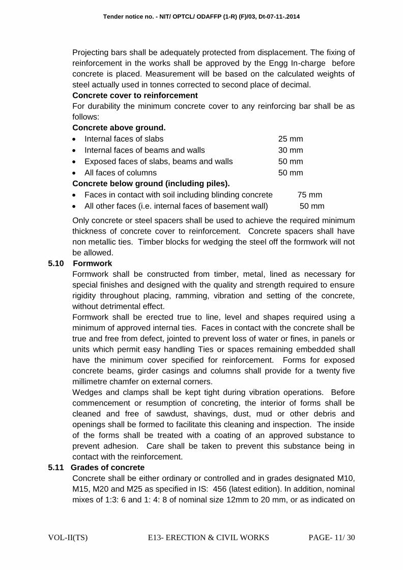
Concrete cover to reinforcement
For durability the minimum concrete cover to any reinforcing bar shall be as
follows:
Concrete above ground.
Internal faces of slabs 25 mm
Internal faces of beams and walls 30 mm
Exposed faces of slabs, beams and walls 50 mm
All faces of columns 50 mm
Concrete below ground (including piles).
Faces in contact with soil including blinding concrete 75 mm
All other faces (i.e. internal faces of basement wall) 50 mm
Only concrete or steel spacers shall be used to achieve the required minimum
thickness of concrete cover to reinforcement. Concrete spacers shall have
non metallic ties. Timber blocks for wedging the steel off the formwork will not
be allowed.
5.10 Formwork
Formwork shall be constructed from timber, metal, lined as necessary for
special finishes and designed with the quality and strength required to ensure
rigidity throughout placing, ramming, vibration and setting of the concrete,
without detrimental effect.
Formwork shall be erected true to line, level and shapes required using a
minimum of approved internal ties. Faces in contact with the concrete shall be
true and free from defect, jointed to prevent loss of water or fines, in panels or
units which permit easy handling Ties or spaces remaining embedded shall
have the minimum cover specified for reinforcement. Forms for exposed
concrete beams, girder casings and columns shall provide for a twenty five
millimetre chamfer on external corners.
Wedges and clamps shall be kept tight during vibration operations. Before
commencement or resumption of concreting, the interior of forms shall be
cleaned and free of sawdust, shavings, dust, mud or other debris and
openings shall be formed to facilitate this cleaning and inspection. The inside
of the forms shall be treated with a coating of an approved substance to
prevent adhesion. Care shall be taken to prevent this substance being in
contact with the reinforcement.
5.11 Grades of concrete
Concrete shall be either ordinary or controlled and in grades designated M10,
M15, M20 and M25 as specified in IS: 456 (latest edition). In addition, nominal
mixes of 1:3: 6 and 1: 4: 8 of nominal size 12mm to 20 mm, or as indicated on
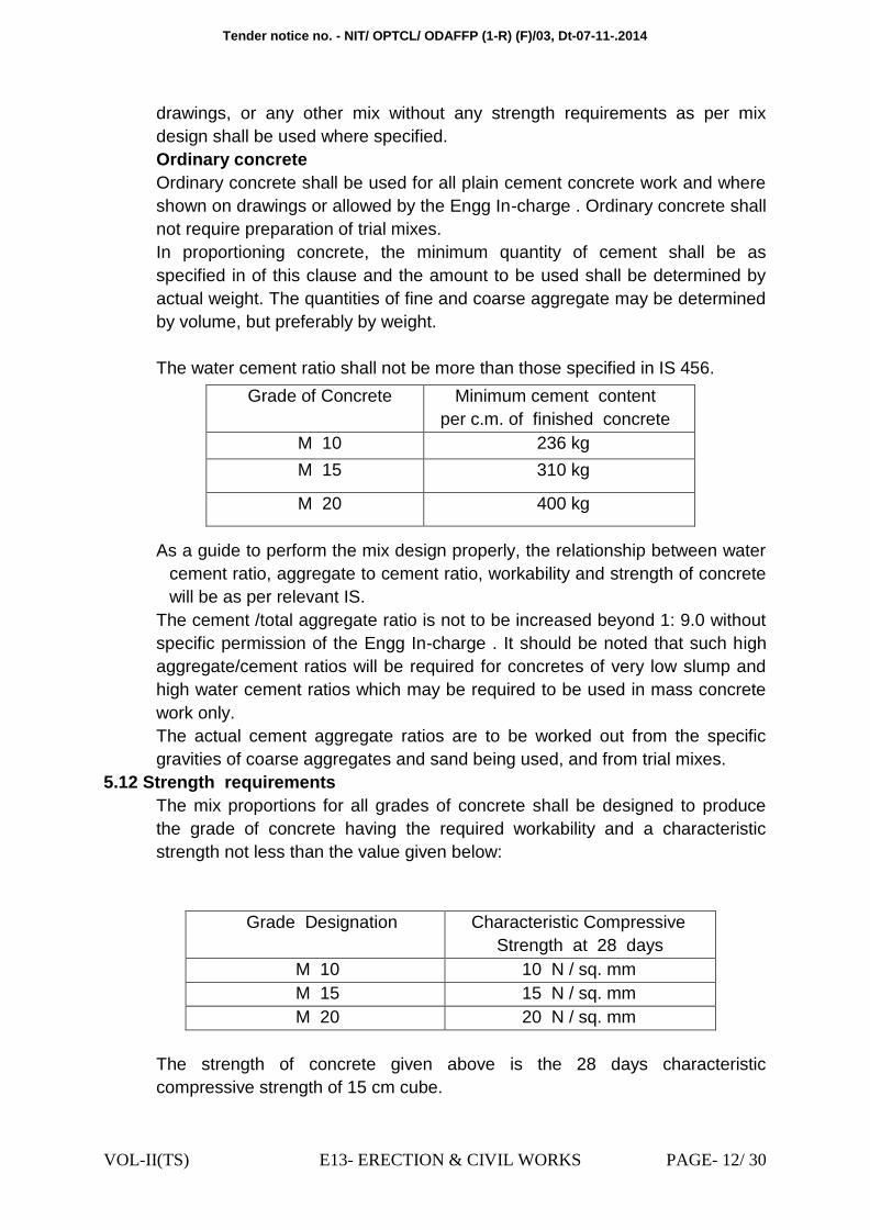
Tender notice no. - NIT/ OPTCL/ ODAFFP (1-R) (F)/03, Dt-07-11-.2014
VOL-II(TS) E13- ERECTION & CIVIL WORKS PAGE- 12/ 30
drawings, or any other mix without any strength requirements as per mix
design shall be used where specified.
Ordinary concrete
Ordinary concrete shall be used for all plain cement concrete work and where
shown on drawings or allowed by the Engg In-charge . Ordinary concrete shall
not require preparation of trial mixes.
In proportioning concrete, the minimum quantity of cement shall be as
specified in of this clause and the amount to be used shall be determined by
actual weight. The quantities of fine and coarse aggregate may be determined
by volume, but preferably by weight.
The water cement ratio shall not be more than those specified in IS 456.
Grade of Concrete Minimum cement content
per c.m. of finished concrete
M 10 236 kg
M 15 310 kg
M 20 400 kg
As a guide to perform the mix design properly, the relationship between water
cement ratio, aggregate to cement ratio, workability and strength of concrete
will be as per relevant IS.
The cement /total aggregate ratio is not to be increased beyond 1: 9.0 without
specific permission of the Engg In-charge . It should be noted that such high
aggregate/cement ratios will be required for concretes of very low slump and
high water cement ratios which may be required to be used in mass concrete
work only.
The actual cement aggregate ratios are to be worked out from the specific
gravities of coarse aggregates and sand being used, and from trial mixes.
5.12 Strength requirements
The mix proportions for all grades of concrete shall be designed to produce
the grade of concrete having the required workability and a characteristic
strength not less than the value given below:
Grade Designation Characteristic Compressive
Strength at 28 days
M 10 10 N / sq. mm
M 15 15 N / sq. mm
M 20 20 N / sq. mm
The strength of concrete given above is the 28 days characteristic
compressive strength of 15 cm cube.
Tender notice no. - NIT/ OPTCL/ ODAFFP (1-R) (F)/03, Dt-07-11-.2014
VOL-II(TS) E13- ERECTION & CIVIL WORKS PAGE- 13/ 30
The placing of concrete shall be a continuous operation with no interruption in
excess of 30 minutes between the placing of continuous portions of concrete.
When fresh concrete is required to be placed on previously placed and
hardened concrete, special care should be taken to clean the surface of all
foreign matter. For securing a good bond and water tight joint, the receiving
surface should be made rough and a rich mortar placed on it unless it has
been poured just before. The mortar layer should be about 15 mm thick with
cement and sand proportion as that of the mix in use, and have the same
water-cement ratio as the concrete to be placed.
After the concrete has been placed it shall be thoroughly compacted by
approved mechanical vibration to a maximum subsidence without segregation
and thoroughly worked around reinforcement or other embedded fixtures into
the correct form and shape. Vibrators must be operated by experienced men
and over vibration shall not be permitted. Care should be taken to ensure that
the inserts, fixtures, reinforcement and formwork are not displaced or
disturbed during placing of concrete. No concrete shall be placed in open
while it rains. If there is any sign of washing of cement and sand, the concrete
shall be entirely removed immediately. Slabs, beams and similar structure
shall be poured in one operation normally. In special circumstances with the
approval of Engg In-charge these can be poured in horizontal layers not
exceeding 50 cm. in depth. When poured in layers, it must be ensured that the
under layer is not hardened. Bleeding of under layer if any shall be effectively
removed.
5.13 Compaction of Concrete
Compaction is necessary for production of good concrete. After the concrete
has been placed it shall be thoroughly compacted by approved mechanical
vibrator to a maximum subsidence without segregation and thoroughly worked
around reinforcement or other embedded fixtures into the correct form and
shape. Vibrators must be operated by experienced men. Care should be taken
to ensure that the inserts, fixtures, reinforcement and formwork are not
displaced or disturbed during the vibration of the concrete. The Contractors
shall provide standby vibrators. Vibration is commonly used method of
compaction of concrete, the use of mechanical vibrators complying with IS
2505, IS 2506, IS 2514 and IS 4656 for compacting concrete is recommended
For all practical purposes, the vibration can be considered to be sufficient
when the air bubbles cease to appear and sufficient mortar appears to close
the surface and facilitate easy finishing operations. The period of vibration
required for a mix depends upon the workability of the mix.
5.14 Curing of Concrete
In order to achieve proper and complete strength of the concrete, the loss of
water from evaporation should be prevented. Eighty to eighty five per cent of
the strength is attained in the first 28 days and hence this 28-day strength is
considered to be the criterion for the design and is called characteristic
Tender notice no. - NIT/ OPTCL/ ODAFFP (1-R) (F)/03, Dt-07-11-.2014
VOL-II(TS) E13- ERECTION & CIVIL WORKS PAGE- 14/ 30
strength. The concrete after setting for 24 hours shall be cured by keeping the
concrete wet continuously for a period of 10 days after laying.
The curing increases compressive strength, improves durability,
impermeability and abrasion resistance. Failure to carry out satisfactory curing
can lead to cracking in the concrete. This in turn can lead to salt attack of the
reinforcement and consequential failure of the structure. If cracks occur in a
structure which are severe enough to affect the structure, the Contractor shall
cut out and replace the defective concrete at his own cost. The Contractor‟s
attention is, therefore, drawn to this particular aspect of proper and adequate
curing
5.15 Removal of formwork
Formwork shall be kept in position fully supported, until the concrete has
hardened and gained sufficient strength to carry itself and any loads likely to be
imposed upon it. Stripping must be effected in such a manner and at such a time
that no shock or other injury is caused to the concrete. The responsibility for
safe removal rests with the Contractor but the Engg In-charge may delay the
time of striking if he deems it necessary.
Minimum periods, in the absence of agreement to the contrary, between
completion of concreting and removal of forms are given below but due regard
must be paid to the method of curing and prevailing conditions during this period.
Removal of forms are to be done as under
i) Sides of foundations, columns, beams and wall 2days
ii) Under side of slabs up to 4.5 m span 7days
iii) Under side of slabs above to 4.5 m span
and underside of beams and arches up to 6m span 14days
iv) Under side of beams and arches above 6m and up to 9m span 21days
6.0 EARTHING : Earth Grid should not be more than TWO meters square. This should be done
by using 75x10 mm GI flats. Earth risers should be 50x6 mm GI flats. All
equipments & metal parts of the Sub-Station should be connected with main
earth grid by using 50x6 GI flats at two different places. The main earth grid
should be laid not less than 600 mm below the finished ground level. The lap
welding should not less than 100 mm. The welding of joints should be done
after removal of Zinc by using Blow lamps. Welding should be done in all four
sides and should be double layer continuous. Before taking up the second
layer welding the deposited flux should be removed. During welding the two
flats should be tightened properly by using „ C „ clamps. Immediately after
welding two layers of anti-corrosive paints should be painted over the welded
portion along with two coats of Black bituminous paints. Before back filling of
earth trenches the welded portion should be covered by wrapping with
bituminous tape properly and also jointing portion should be covered with PCC
(1:2:4) mix. The backfilling of earth pits and trenches should be done with
powered loam soil mixed with Bentonate powder (10:1) mix.

Tender notice no. - NIT/ OPTCL/ ODAFFP (1-R) (F)/03, Dt-07-11-.2014
VOL-II(TS) E13- ERECTION & CIVIL WORKS PAGE- 15/ 30
All equipments, steel structures etc should be connected with Main earth mat
at two rows separately. All LAs, PTs , Columns having spikes should
individually connected with individual Pipe electrodes and again should be
connected with main earth grid at two separate places. The Neutral of Power
Transformer should be connected with two separate pipe electrodes and again
connected with main earth electrodes at two separate places. The separation
distance between each pipe electrodes should not be less than 2 mts. The
back filling of pipe electrodes should be done in layer of Charcoal, Salt & loam
soil mixed with Bentonate power.
There should be a closely spaced earth grid ( 1.5 mts square having .5 mts
spacing) below the mechanism boxes of each Isolators & AB switches. In Sub-
station the diameter of pipe electrode should not be less than 50 mm. The
Flange( 50x6) mm GI flat should be welded in all sides with Pipe electrode. In
each face of Flange there should be two nos 17.5 mm hole to accommodate
16 mm GI Bolt nut with 1 no spring washer.
The fencing of sub-station should not directly connected with main earth grid.
There should be a separate earth grid ( 75x10) mm GI flat 2 mts away from
fence and should be connected rigidly with the fence at an interval of 5 mts.
There should be one 50x6 mm earth flat run over the cable rack and should be
connected with main earth grid at an interval of 5 mts The jointing portion of
earth flats over the ground should be painted with two coats of Anti-corrosive
paints and two coats of good quality of Aluminium paints (Berger/Asian
paints).
The water hydrant system should be provided in the areas where earth
resistivity more and soil is latetarite and sandy in nature (Areas like BBSR,
Khurda , Puri etc) as per the direction of Engineer in charge. Each handles of
Isolators/AB switches etc should be connected with earth grid by using flexible
Tinned Copper earth bonds. In each earth switches TWO nos flexible earth
bonds should be provided. Each earth pits having pipe electrodes should be
provided 250 mm Brick wall chambers with RCC cover Slab.
6.1 (A) G.I. Flat (75x 10 mm) & G.I.Flat (50 x 6 mm)
The specification covers manufacture, testing and supply of Galvanized Steel
flat for Earthing arrangements.
I. APPLICABLE STANDARDS:
Materials shall conform to the latest applicable Indian standards. In case
bidders offer steel section and supports conforming to any other international
specifications which shall be equivalent or better than IS, the same is also
acceptable.
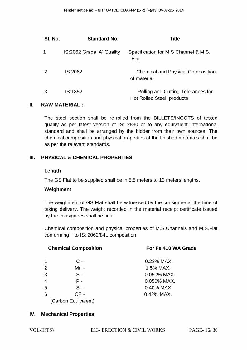
Tender notice no. - NIT/ OPTCL/ ODAFFP (1-R) (F)/03, Dt-07-11-.2014
VOL-II(TS) E13- ERECTION & CIVIL WORKS PAGE- 16/ 30
Sl. No. Standard No. Title
1 IS:2062 Grade „A‟ Quality Specification for M.S Channel & M.S.
of material Flat
2 IS:2062 Chemical and Physical Composition
of material
3 IS:1852 Rolling and Cutting Tolerances for
Hot Rolled Steel products
II. RAW MATERIAL :
The steel section shall be re-rolled from the BILLETS/INGOTS of tested
quality as per latest version of IS: 2830 or to any equivalent International
standard and shall be arranged by the bidder from their own sources. The
chemical composition and physical properties of the finished materials shall be
as per the relevant standards.
III. PHYSICAL & CHEMICAL PROPERTIES
Length
The GS Flat to be supplied shall be in 5.5 meters to 13 meters lengths.
Weighment
The weighment of GS Flat shall be witnessed by the consignee at the time of
taking delivery. The weight recorded in the material receipt certificate issued
by the consignees shall be final.
Chemical composition and physical properties of M.S.Channels and M.S.Flat
conforming to IS: 2062/84L composition.
Chemical Composition For Fe 410 WA Grade
1 C - 0.23% MAX.
2 Mn - 1.5% MAX.
3 S - 0.050% MAX.
4 P - 0.050% MAX.
5 SI - 0.40% MAX.
6 CE - 0.42% MAX.
(Carbon Equivalent)
IV. Mechanical Properties
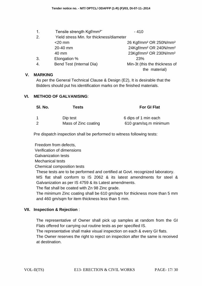
Tender notice no. - NIT/ OPTCL/ ODAFFP (1-R) (F)/03, Dt-07-11-.2014
VOL-II(TS) E13- ERECTION & CIVIL WORKS PAGE- 17/ 30
1. Tensile strength Kgf/mm²ˉ - 410
2. Yield stress Min. for thickness/diameter
<20 mm 26 Kgf/mm² OR 250N/mm²
20-40 mm 24Kgf/mm² OR 240N/mm²
40 mm 23Kgf/mm² OR 230N/mm²
3. Elongation % 23%
4. Bend Test (Internal Dia) Min-3t (this the thickness of
the the material)
V. MARKING
As per the General Technical Clause & Design (E2), It is desirable that the
Bidders should put his identification marks on the finished materials.
VI. METHOD OF GALVANISING:
Sl. No. Tests For GI Flat
1 Dip test 6 dips of 1 min each
2 Mass of Zinc coating 610 gram/sq.m minimum
Pre dispatch inspection shall be performed to witness following tests:
Freedom from defects,
Verification of dimensions
Galvanization tests
Mechanical tests
Chemical composition tests
These tests are to be performed and certified at Govt. recognized laboratory.
MS flat shall conform to IS 2062 & its latest amendments for steel &
Galvanization as per IS 4759 & its Latest amendments.
The flat shall be coated with Zn 98 Zinc grade.
The minimum Zinc coating shall be 610 gm/sqm for thickness more than 5 mm
and 460 gm/sqm for item thickness less than 5 mm.
VII. Inspection & Rejection :
The representative of Owner shall pick up samples at random from the GI
Flats offered for carrying out routine tests as per specified IS.
The representative shall make visual inspection on each & every GI flats.
The Owner reserves the right to reject on inspection after the same is received
at destination.
Tender notice no. - NIT/ OPTCL/ ODAFFP (1-R) (F)/03, Dt-07-11-.2014
VOL-II(TS) E13- ERECTION & CIVIL WORKS PAGE- 18/ 30
6.2 (C) Earth Electrode (50/40 NB 3.0 Mtr Length)
I. Qualification Criteria of sub vendor / Manufacturer:-
The prospective bidder may source Earth Electrode from sub vendors /
manufacturers who must qualify all the following requirements :
a) The sub vendor /manufacturer must have successfully carried out Type
Test of similar item from any NABL Accredited Laboratory within the last 5
years, prior to the date of submission of the bid.
b) The manufacturer should have supplied at least 200 no.s to electricity
supply utilities / PSUs. The bidder should enclose Performance Certificates
from the above users issued in the name of the manufacturer / sub vendor as
proof of successful operation in field.
II. Scope :-
This specification provides for design, manufacturing, testing before dispatch,
supply & delivery of Earthing Device (Heavy Duty) (for use in line (40x3000)
mm & SS(50x3000 mm), as per enclosed Drawing.
III. APPLICABLE STANDARDS :-
The Earthing Device must be made out of 50 mm for S/S,40 mm for line
(Heavy Gauge- No minus Tolerance allowed) Wall thickness Hot Dip G.I. Pipe
(as per IS ;- 1239,m Part-1, 1990 of reputed Make(TATA/Jindal) & 3.0 mtrs
length tapered finished smooth at one end for a length of 75 mm & Clamp at
the other end.
Staggered drills hole of 12 mm Dia of interval of 150mm shall be made before
galvanization.
The GI Earthing Clamp/ Strip (C- Clamp Type) is to be of 50mm width, 6mm
thickness & flange length of 65 mm in each side. This should be suitable for
termination of 4 nos of GI Flat earth electrodes. The Clamp/ Strip & Earthing
pipe after fabrication will be hot dip galvanized confirming to IS: 2629/85 with
latest amendments. The clamp shall have two holes in both sides suitable for
16 mm GI Bolts & Nuts.
6.3 . (D)
Tender notice no. - NIT/ OPTCL/ ODAFFP (1-R) (F)/03, Dt-07-11-.2014
VOL-II(TS) E13- ERECTION & CIVIL WORKS PAGE- 19/ 30
Metal parts of all equipment other than those forming part of an electrical
circuit shall be connected directly to the main earth system via two separate
conductors of adequate capacity at two different points.
All main members of structural steelworks shall be earthed by galvanised iron
flat connections bonded by welding or bolting to the steelworks.
Connections to apparatus and structures shall be made clear of ground level,
preferably to a vertical face and protected as appropriate against electrolytic
corrosion. They shall be made between clean surfaces and of sufficient size
and pressure to carry the rated short circuit current without damage.
Earth bars installed directly into the ground should normally be laid bare and
the trench back-filled with a fine top soil. Where the soil is of a hostile nature,
special precautions must be taken to protect the earth bar. Wherever required
to achieve the required resistance bentonite powder to be mixed in lom/ black
cotton crushed soil in 1: 6 proportion is permissible, the method used being
subject to the agreement of the Engg. Incharge . In the event of bentonite
powder being adopted, water supply through conduit to the area must be
supplemented and regulated to keep the surface / mat moisture absorbent.
Joints in earth bars+ shall be welded and then coated with a suitable anti-
corrosion protection treatment.
Facilities shall be provided on the earth bar run between equipment and the
base of structures, comprising a looped strip, so as to permit the attachment of
portable earth connections for maintenance purposes.
The cross sectional area of the earth bar and connections shall be such that
the current density is not greater than 100 A/mm2 for a 3 second fault duration.
7.0 WIRING, CABLING AND CABLE INSTALLATION
7.1 Cubicle wiring
Panels shall be complete with interconnecting wiring between all electrical
devices in the panels. External connections shall be achieved through terminal
blocks. Where panels are required to be located adjacent to each other all
inter panel wiring and connections between the panels shall be carried out
internally. The Contractor shall furnish a detailed drawing of such inter panel
wiring. The Contractor shall ensure the completeness and correctness of the
internal wiring and the proper functioning of the connected equipment.
All wiring shall be carried out with 1.1 kV grade, PVC insulated, single core,
stranded copper wires. The PVC shall have oxygen index not less than ‘29’
and Temperature index not less than 250C. The wires shall have annealed
copper conductors of adequate size comprise not less than three strands.
The minimum cross sectional area of the stranded copper conductor used for
internal wiring shall be as follows :
a) All circuits excepting CT circuits and energy metering circuit of VT 2.5
sq.mm
Tender notice no. - NIT/ OPTCL/ ODAFFP (1-R) (F)/03, Dt-07-11-.2014
VOL-II(TS) E13- ERECTION & CIVIL WORKS PAGE- 20/ 30
b) All CT circuits and metering circuit of VT 2.5 sq. mm
All internal wiring shall be supported, neatly arranged, readily accessible and
connected to equipment terminals and terminal blocks. Wiring gutters and
troughs shall be used for this purpose.
Cubicle connections shall be insulated with PVC to IEC 227. Wires shall not
be jointed or teed between terminal points.
Bus wires shall be fully insulated and run separately from one another.
Auxiliary bus wiring for AC and DC supplies, voltage transformer circuits,
annunciation circuits and other common services shall be provided near the
top of the panels running throughout the entire length of the panel suite.
Longitudinal troughs extending throughout the full length of panel shall be
preferred for inter panel wiring.
All inter connecting wires between adjacent panels shall be brought to a
separate set of terminal blocks located near the slots of holes meant for the
passage of the interconnecting wires. Interconnection of adjacent panels on
site shall be straightforward and simple. The bus wires for this purposes shall
be bunched properly inside each panel.
Wire termination shall be made with solderless crimping type and tinned
copper lugs which firmly grip the conductor. Insulated sleeves shall be
provided at all the wire terminations. Engraved core identification plastic
ferrules marked to correspond with panel wiring diagram shall be fitted at both
ends of each wire. Ferrules shall fit tightly on the wire and shall not fall off
when the wire is disconnected from terminal blocks. Numbers 6 and 9 shall not
be included for ferrules purposes unless the ferrules have numbers
underscored to enable differentiation. (i.e. 6 and 9 ).
Fuses and links shall be provided to enable all circuits in a cubicle, except a
lighting circuit, to be isolated from the bus wires.
The DC trip and AC voltage supplies and wiring to main protective gear shall
be segregated from those for back-up protection and also from protective
apparatus for special purposes. Each such group shall be fed through
separate fuses from the bus wires. There shall not be more than one set of
supplies to the apparatus comprising each group. All wires associated with the
tripping circuits shall be provided with red ferrules marked “Trip”.
It shall be possible to work on small wiring for maintenance or test purposes
without making a switchboard dead.
The insulation material shall be suitably coloured in order to distinguish
between the relevant phases of the circuit.
When connections rated at 380 volt and above are taken through junction
boxes they shall be adequately screened and “DANGER” notices shall be
affixed to the outsides of junction boxes or marshalling kiosk.

Tender notice no. - NIT/ OPTCL/ ODAFFP (1-R) (F)/03, Dt-07-11-.2014
VOL-II(TS) E13- ERECTION & CIVIL WORKS PAGE- 21/ 30
Where connections to other equipment and supervisory equipment are
required the connections shall be grouped together.
7.2 LV power cabling
LVAC cable terminals shall be provided with adequately sized, hot pressed,
cast or crimp type lugs. Where sweating sockets are provided they shall be
without additional clamping or pinch bolts. Where crimp type lugs are provided
they shall be applied with the correct tool and the crimping tool shall be
checked regularly for correct calibration. Bi-metallic joints between the
terminals and lugs shall be provided where necessary.
Terminals shall be marked with the phase colour in a clear and permanent
manner.
A removable gland plate shall be provided by the Contractor. The Contractor
shall be responsible for drilling the cable gland plate.
Armoured cables shall be provided with suitable glands for terminating the
cable armour and shall be provided with an earthing ring and lug to facilitate
connection of the gland to the earth bar.
7.3 Multi-core cables and conduit wiring
External multi-core cabling between items of main and ancillary equipment
shall form part of the Contract Works and shall consist of un-armoured multi-
core cable with stranded copper conductors PVC insulated and PVC over
sheathed complying with the requirements of IEC 227 and 228 as applicable.
Multi-core cable for instrumentation and control purposes shall be supplied
with 2.5 mm2 stranded copper cores. Multi-core cables for CT and VT circuits
shall be supplied with two by 2.5 mm2 stranded copper cores and the cores
shall be identified by the phase colour.
Where conduit is used the runs shall be laid with suitable falls and the lowest
parts of the run shall be external to the equipment. All conduit runs shall be
adequately drained and ventilated. Conduits shall not be run at or below
ground level.
Multi-core cable tails shall be so bound that each wire may be traced to its
cable without difficulty. All multi-core cables shall be provided with 20 % spare
cores and the spare cores shall be numbered and terminated at a terminal
block in the cubicle. Where cables are terminated in a junction box and the
connections to a relay or control cubicle are continued in conduit, the spare
cores shall be taken through the conduit and terminated in the cubicle. The dc
trip and ac voltage circuits shall be segregated from each other as shall the
circuits to main protective gear be segregated from those for back-up
protection.
Tender notice no. - NIT/ OPTCL/ ODAFFP (1-R) (F)/03, Dt-07-11-.2014
VOL-II(TS) E13- ERECTION & CIVIL WORKS PAGE- 22/ 30
The screens of screened pairs of multi-core cables shall be earthed at one end
of the cable only. The position of the earthing connections shall be shown
clearly on the diagram.
All wires on panels and all multi-core cable cores shall be crimped with the
correct size of crimp and crimping tool and will have ferrules which bear the
same number at both ends. At those points of interconnection between the
wiring carried out by separate contractors where a change of number cannot
be avoided double ferrules shall be provided on each wire. The change of
numbering shall be shown on the appropriate diagram of the equipment. The
same ferrule number shall not be used on wires in different circuits on the
same panels.
The Contractor shall provide a two (2) metre loop of spare cable at both ends
of all multi-core cable runs and shall leave sufficient lengths of tails at each
end of the multi-core cables to connect up to the terminal boards. The
Contractor shall also strip, insulate, ring through and tag the tails and shall
also seal the cable boxes. The Contractor shall be responsible for re-checking
the individual cores and for the final connecting up and fitting of numbered
ferrules within all equipment provided on this contract.
The drilling of gland plates, supply and fitting of compression glands and
connecting up of power cables included in the Contract scope of work shall be
carried out under this contract.
8.0 Laying and Installing of cables
8.1 General
For cable laying the following shall apply:
a) Switchyard area in concrete cable troughs (cable trench having cable
racks with cable trays)
b) Control Room On cable racks consisting of slotted type and ladder type
cable trays
c) Buildings Conduits
Directly buried cables shall be used wherever necessary with the approval of
Engg. Incharge .
8.2 Laying of cable
Cables shall be laid in concrete troughs provided under this contract or drawn
into pipes or ducts or on cable racks or directly buried as may be required by
the Engg. Incharge . Concrete troughs shall be designed so that the cables
are supported on cable support systems and the supports shall be arranged
so as to allow the segregation of power, control (including CT and VT circuits)
and communications cables onto different layers of cable supports. All cable
supports shall be earthed in accordance with IS 3043. The minimum vertical
separation between layers of cable tray shall be not less than 300 mm.

Tender notice no. - NIT/ OPTCL/ ODAFFP (1-R) (F)/03, Dt-07-11-.2014
VOL-II(TS) E13- ERECTION & CIVIL WORKS PAGE- 23/ 30
The cable support system shall be designed and constructed to carry the
required cables without undue crowding of the supports and without
overloading the supports. The maximum number of layers of cable that shall
be permitted on a single cable support shall be three. The width of the cable
supports shall be selected to ensure that the supports are not crowded, the
cable supports are not overloaded and that sufficient space is provided in the
cable trough to allow for personnel access during and after cable installation.
The width of cable supports should not exceed 750 mm.
Cables shall be laid direct in the ground only at the discretion of the Engg.
Incharge . All cables laid direct in the ground outside buildings shall be laid in
a trench and protected by reinforced concrete slabs or cable tiles.
For auxiliary cables the top of the slab or tile shall be at a depth not less than
300 mm below the surface of the ground and there shall be a layer of fine well
packed riddled earth 75 mm thick in between the cable and the bottom of the
trench and between the top of the cable and the underside of the slab.
The Contractor shall be responsible for the proper laying of all cables in the
ground. Where cables in the same trench are laid over each other, they shall
be separated by not less than 75 mm of riddled earth. The riddled earth used
for this purpose shall have been passed through a screen having a 12 mm
square mesh.
Where cables pass under roadways they shall be laid in pipes at a depth not
less than 800 mm below the surface.
The Contractor shall be responsible for the excavation of trenches which shall
include all pumping and baling required and the provision of all necessary
labour, plant, tools, water, additional soil, fuel or motor power for such
purposes.
Cables in trenches will be inspected by the Engg. Incharge before the
trenches are backfilled.
The running of communications and power cables along the same route shall
be avoided as far as possible. Where this is not possible they shall be
segregated, the one group from the other. Power and communication cables
shall be laid in separate tiers. For other than directly buried cables the order of
laying of various cables shall be as follows:
a) Power cables on top tiers.
b) Control/ instrumentation and other service cables in bottom tiers.
8.3 Cable tags and markers
Each cable and conduit run shall be tagged with numbers that appear in the
cable and conduit schedule.
Tender notice no. - NIT/ OPTCL/ ODAFFP (1-R) (F)/03, Dt-07-11-.2014
VOL-II(TS) E13- ERECTION & CIVIL WORKS PAGE- 24/ 30
The tag shall be of aluminum with the number punched on it and securely
attached to the cable conduit by not less than two turns of 20 SWG GI wire
conforming to IS 280. Cable tags shall be of rectangular shape for power
cables and of circular shape for control cables.
Location of cables laid directly in the ground shall be clearly indicated with
cable marker made of galvanised iron plate.
Location of buried cable joints shall be indicated with a cable marker having an
additional inscription "Cable joint".
Cable markers shall project 150 mm above ground and shall be spaced at an
interval of 30 meters and at every change in direction. They shall be located
on both sides of road and drain crossings.
Cable tags shall be provided on all cables at each end (just before entering
the equipment enclosure), on both sides of a wall or floor crossing, on each
duct, conduit entry and at every twenty meters (20 m) in cable tray/trench
runs. Cable tags shall be provided inside switchgear, motor control centres,
control and relay panels etc. and wherever required for cable identification
when a number of cables enter together through a gland plate.
The price of cable tags and markers shall be included in the installation rates
for cables/conduits quoted by the Bidder.
8.4 Cable supports and cable tray mounting arrangements in control room
The control room will normally be provided with embedded steel inserts on
concrete floors/walls for the purpose of cabling in the control room. The
supports shall be secured by welding to these inserts or available building
steel structures. However, in cases where no such embedded steel inserts are
available, the same shall have to secure to the supports on walls or floors by
suitable anchoring.
8.5 Cable support structure in switchyard cable trenches
The contractor shall fabricate and install cable support structures in cable
trenches. These supports shall be provided at 750 mm spacing along the run
of cable trenches.
Cable supports and cable racks shall be fabricated from standard structural
steel members, channels, angles and flats of required size. The fabrication.
welding and erection of these structures shall conform to the relevant clauses
of this Specification, in addition to the specification given herein.
8.6 Termination of cables and wires
Where cables leave the apparatus in an upward direction the cable boxes
shall be provided with a barrier joint to prevent leakage of cable oil or
Tender notice no. - NIT/ OPTCL/ ODAFFP (1-R) (F)/03, Dt-07-11-.2014
VOL-II(TS) E13- ERECTION & CIVIL WORKS PAGE- 25/ 30
compound into the apparatus. Where cable cores are liable to contact with oil
or oil vapour the insulation shall be unaffected by oil.
PVC sheathed cables shall be terminated by compression glands complying
with BS 6121 (or equivalent).
Auxiliary PVC insulated cables shall be terminated with compression type
glands, clamps or armour clamps complete with all the necessary fittings.
Colours shall be marked on the cable box, cable tail ends and single core
cables at all connecting points and/or any positions the Engg. Incharge may
determine. Cable boxes shall be provided with suitable labels indicating the
purpose of the supply where such supply is not obvious or where the Engg.
Incharge may determine.
All cables shall be identified and shall have phase colours marked at their
termination.
All incoming and outgoing connections shall be terminated at a terminal block.
Direct termination into auxiliary switches will not be accepted.
9.0 SUPPLY VOLTAGE
The auxiliary supply voltages on site shall be as follows:
Nominal
Voltage V
Variation Frequency Hz
or DC
Phas
e
Wires Neutral
Connection
430 ±10% 50 (-5%, +3%) 3 4 Solidly earthed
230 ±10% 50 (-5%, +3%) 1 2 Solidly earthed
24 DC DC 2
10.0Contractor's field operation
10.1General
The Contractor shall inform the Engg. Incharge in advance of field activity
plans and schedules for carrying-out each part of the works. Any review of
such plans or schedules or methods of work by the Engg. Incharge shall not
relieve the Contractor of any of his responsibilities towards the field activities.
Such reviews shall not be considered as an assumption of any risk or liability
by the Employer or any of his representatives, and no claim of the Contractor
will be entertained because of the failure or inefficiency of any such plan or
schedule or method of work reviewed. The Contractor shall be solely
responsible for the safety, adequacy and efficiency of plant and equipment
and his erection methods.
10.2 Facilities to be provided by the contractor
10.3 Unloading
Contractor shall make his own arrangement for unloading the equipment at
site.
10.4 Tools, tackle and scaffoldings
Tender notice no. - NIT/ OPTCL/ ODAFFP (1-R) (F)/03, Dt-07-11-.2014
VOL-II(TS) E13- ERECTION & CIVIL WORKS PAGE- 26/ 30
The Contractor shall provide all the construction equipment tools, tackle and
scaffoldings required for offloading, storage, pre-assembly, erection, testing
and commissioning of the equipment covered under the Contract. He shall
submit a list of all such materials to the Engg. Incharge before the
commencement of pre-assembly at Site. These tools and tackles shall not be
removed from the Site without the written permission of the Engg. Incharge .
The Contractor shall maintain an accurate and exhaustive record detailing all
equipment received by him for the purpose of erection and keep such record
open for the inspection of the Engg. Incharge .
All equipment shall be handled carefully to prevent any damage or loss. All
equipment stored shall be properly protected to prevent damage. Equipment
from the store shall be moved to the actual location at an appropriate time so
as to avoid damage of such equipment at Site.
All the materials stored in the open or dusty location shall be covered with
suitable weather-proof and flameproof covering material.
The Contractor shall be responsible for making suitable indoor facilities for the
storage of all equipment which requires to be kept indoors.
11.0 SITE CLEARANCE
11.1 Clearing and uprooting of tree
The work shall also consist of numbering of trees, removing and disposing of
all materials such as trees, bushes, woods, shrubs, grass, stumps, rubbish,
rank vegetation, roots, foreign materials, etc., which in the opinion of the Engg
In-charge are unsuitable for incorporation in the works, from within the limits
and such other areas as may be specified on the drawings or directed by the
Engg In-charge . Clearing and uprooting of tree shall be performed in advance
of earthwork operations and in accordance with the requirements of these
Specifications and taking prior permission from forest department. During
clearing and grubbing, the contractor shall take all adequate precautions
against soil erosion, water pollution etc., and where required undertake
additional works to that effect.
11.2 Programme
The Contractor shall construct the works in compliance with the outline
programme appended to the Bidding Document, and shall submit for the
approval of the Engg In-charge a detailed programme in accordance with the
requirements of this Specification.
11.3 Inclement weather
As per relevant Code, during hot weather, precautions shall be taken to avoid
premature stiffening of the fresh concrete mix and to reduce water absorption
and evaporation losses. During hot weather (atmospheric temperature above
40 degree C) or cold weather (atmospheric temperature at or below 5deg.C)
concreting shall be done as per the procedure set out in IS 7861.
Tender notice no. - NIT/ OPTCL/ ODAFFP (1-R) (F)/03, Dt-07-11-.2014
VOL-II(TS) E13- ERECTION & CIVIL WORKS PAGE- 27/ 30
11.4 STANDARDS
All Civil works shall be carried out as per applicable Indian Laws, latest
revision of International Standards and Codes. All materials shall be of best
quality confirming to relevant Indian Standards and Codes.
Civil works shall be designed to the required service conditions and /or loads
as specified elsewhere in this Specification or implied as per National and
International Standards.
12.0 MATERIALS AND WORKMANSHIP
12.1 General
All materials used in the works shall be new and of the best quality of their
respective kinds. They shall comply with the requirements of the latest edition
of any relevant Indian Standard or Code of Practice where such exist, and
current at the date of tendering.
All workmanship shall be of the highest standard, and shall be executed by
competent men skilled in their respective trades.
12.2 Samples
In addition to the special provisions made in this specification for sampling and
testing of materials by particular methods, samples of any materials and
workmanship proposed to be used in the Works may be called for at any time
during the Contract by the Engg In-charge and shall be furnished by the
Contractor without delay and at the expense of the Contractor. Samples when
approved, shall be regarded as the acceptable standard, and any material or
workmanship subsequently not complying with that standard shall be rejected
and replaced by those of acceptable standard at the expense of the
Contractor. Sample storage boxes shall be provided by the Contractor free of
cost if requested by the Engg In-charge .
12.3 Tests
Whenever considered desirable by the Engg In-charge , Inspectors may be
sent to manufacturer‟s or subcontractors‟ premises to test materials or
supervise their manufacture.
Where specified or requested the Contractor shall obtain from the
manufacturer and send to the Engg In-charge certificates of test, proof
sheets, mill sheets, etc., showing that materials have been tested in
accordance with this Specification or the relevant Indian Standard.
Notwithstanding any tests which may be directed to be carried out at a
manufacturer‟s and/or subcontractor‟s works, the Engg In-charge may carry
out any tests or further tests he considers necessary or desirable after delivery
of materials to the Site.
The Contractor shall provide all labour, equipment and facilities necessary for
carrying out the tests both in works and on site.
The cost of routine tests required by IS and this Specification shall be borne by
the Contractor. The cost of other tests shall be borne in accordance with the
Conditions of Contract.
Tender notice no. - NIT/ OPTCL/ ODAFFP (1-R) (F)/03, Dt-07-11-.2014
VOL-II(TS) E13- ERECTION & CIVIL WORKS PAGE- 28/ 30
12.4 Names of suppliers and copies of orders
If so required, and before ordering material of any description, the Contractor
shall submit for approval the names of makers or suppliers proposed. Copies
of orders shall also be submitted if so required. The Engg In-charge may at
any time withdraw his previously given approval to obtaining materials from
any maker or supplier should such maker or supplier fail to supply materials of
the specified quality or quantity in the requisite time.
12.5 Rejection of materials and workmanship
The Engg In-charge shall at any time have power to reject materials and
workmanship not complying with this Specification or with the approved
Drawings. Materials so rejected shall be immediately removed from site and
replaced by materials of an approved standard at the expense of the
Contractor. Rejected workmanship shall be broken out and replaced by work
of an acceptable standard including the supply of new materials by the
Contractor, at the expense of the Contractor, and without delay.
13.0 Erection of Station Transformers
13.1 General
As a part of this scheme, there is a provision to install station Transformer in
the Source Sub-Station and distribution transformers on 11 kV line. The
contractor shall transport the transformer along with the distribution board
(OSM) then install, test and commission.
a. The contractor‟s scope is to install distribution transformers on DP
structures up to 100 KVA and Station Transformer on plinth foundation
including all support structures, channels, clamps, nut & bolts etc for ST and
all other accessories. On 11 kV side, the accessories would be LA, A.B.
Switch & HG fuse as specified while on LT side the contractor shall install LT
Distribution Box. The construction of foundation is in the scope of contractor
as per the approved drawings. Any other item, not specifically mentioned but
necessary for safe operation of the distribution transformer is deemed to be
included in the scope of the contractor.
b. The mounting of LTDB shall be same as that for ST and provision shall be
kept for it. LTDB shall be used to take off LT feeders and service connections
as well. Distribution box shall have proper locking arrangement.
c. The location for installation of ST shall be specified by the owner.
d. In rural areas 10 mtr DP structure using PSC poles should be considered
where as 150x150 RS Joist are to be used in place of PSC poles in urban
areas.
e. All steel structures including nuts bolts, fasteners etc should be hot dip
galvanized.
13.2 Erection of Distribution Transformers

Tender notice no. - NIT/ OPTCL/ ODAFFP (1-R) (F)/03, Dt-07-11-.2014
VOL-II(TS) E13- ERECTION & CIVIL WORKS PAGE- 29/ 30
All distribution transformers shall be installed on 11 kV line DP structures /
Plinths. Bimetallic connectors shall be provided on HT side of ST. The
connectors shall be as per REC specifications.
The HT side connections shall be made with AAA conductor. LT side
connections from transformer bushing to MCCB of LTDB shall be made by
providing single core Al. un-armoured XLPE LT cable of suitable size and
support. The outgoings from MCCB of LTDB to the overhead line are also to
be made by providing single core Al. un-armoured XLPE LT cable of suitable
size. In both the cases suitable clamping (made from 50x6mm GI Flats with GI
Bolts & nuts) arrangement (3nos. at transformer side & 4 nos. at line side) with
cushioning, cable gland and end termination kit at both ends shall be provided.
The outgoing cable of LTDB has to be connected to the overhead LT line by
providing minimum 2 nos. of 3-bolted (M-12) type PG clamps. Required layers
of ampere tape and PVC tape are to be wrapped as per requirement.
In case of AB cables directly emanating from the LTDB to LT lines, suitable
clamping arrangement with the pole as mentioned above shall be made.
Necessary tension clamps, dead end clamps etc. shall be provided on the pole
for holding the AB cable properly so that the load of the cable shall not be
transferred to LTBD. The contractor shall provide all such clamps, nuts & bolts
at no extra cost to the owner.
The contractor shall provide and install a Sign Board of 1ft x 1 ft size at each
DT location. The sign board shall be mounted on the pole with suitable
clamps. The board shall be of 1.6 mm (min) thick GI sheet and epoxy painted (
minimum paint thickness 75 micron) The lay out & the content to be written on
the board shall be decided during detailed engineering. The boards shall be
prepared through screen printing or better technology. The cost of providing
and installing the board shall be included in the quoted rates for ST erection.
All materials required for completion of job in all respect beyond owner
supply has to be approved by the owner prior to procurement. During
procurement, contractor supply items should also be inspected and
tested including third party unless otherwise waived out.
13.3 Sub-station Fencing
Goat mesh fencing as per BoQ details of size 4.5x4.75x 1.6 meter for plinth
mounted S/s & 4.5x2.5x1.6 meter for DP mounted S/s shall be constructed
with provision for a Grill gate of size 1.5x1 meter height.
13.4 Earthing of Distribution Sub-stations
Five nos. 50mm dia, 3 mtr. Long, heavy gauge Pipe (SAIL/RINL/TATA)
earthings shall be provided for the distribution Sub-station complying with
relevant IS. Adequate quantity of charcoal and salt shall be used to keep the
earth resistance low. Two connections from transformer neutral, two nos. from
HV side LAs, one from handle of AB switch, transformer body & DP structure
shall be provided to the pipe earths. All the five pits shall be connected to an

Tender notice no. - NIT/ OPTCL/ ODAFFP (1-R) (F)/03, Dt-07-11-.2014
VOL-II(TS) E13- ERECTION & CIVIL WORKS PAGE- 30/ 30
earth grid with 24mtr. long 50x10mm size GI Flats at a depth of 600mm below
the ground level for plinth mounted S/s and for DP mounted the same is of 14
mtr. long. The earth risers should be with 50x6 mm GI Flats requiring 34mtrs
in both type of S/s.
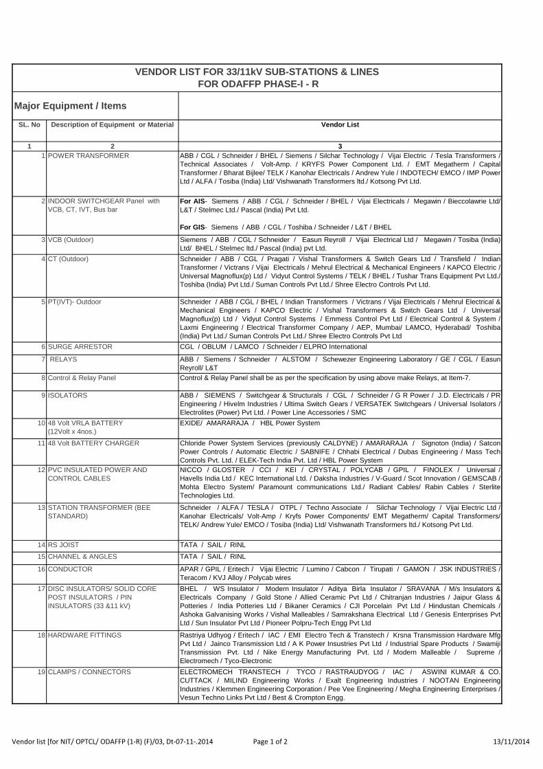
SL. No Description of Equipment or Material Vendor List
1 2 3
1 POWER TRANSFORMER ABB / CGL / Schneider / BHEL / Siemens / Silchar Technology / Vijai Electric / Tesla Transformers /
Technical Associates / Volt-Amp. / KRYFS Power Component Ltd. / EMT Megatherm / Capital
Transformer / Bharat Bijlee/ TELK / Kanohar Electricals / Andrew Yule / INDOTECH/ EMCO / IMP Power
Ltd / ALFA / Tosiba (India) Ltd/ Vishwanath Transformers ltd./ Kotsong Pvt Ltd.
2 INDOOR SWITCHGEAR Panel with
VCB, CT, IVT, Bus bar
For AIS- Siemens / ABB / CGL / Schneider / BHEL / Vijai Electricals / Megawin / Bieccolawrie Ltd/
L&T / Stelmec Ltd./ Pascal (India) Pvt Ltd.
For GIS- Siemens / ABB / CGL / Toshiba / Schneider / L&T / BHEL
3 VCB (Outdoor) Siemens / ABB / CGL / Schneider / Easun Reyroll / Vijai Electrical Ltd / Megawin / Tosiba (India)
Ltd/ BHEL / Stelmec ltd./ Pascal (India) pvt Ltd.
4 CT (Outdoor) Schneider / ABB / CGL / Pragati / Vishal Transformers & Switch Gears Ltd / Transfield / Indian
Transformer / Victrans / Vijai Electricals / Mehrul Electrical & Mechanical Engineers / KAPCO Electric /
Universal Magnoflux(p) Ltd / Vidyut Control Systems / TELK / BHEL / Tushar Trans Equipment Pvt Ltd./
Toshiba (India) Pvt Ltd./ Suman Controls Pvt Ltd./ Shree Electro Controls Pvt Ltd.
5 PT(IVT)- Outdoor Schneider / ABB / CGL / BHEL / Indian Transformers / Victrans / Vijai Electricals / Mehrul Electrical &
Mechanical Engineers / KAPCO Electric / Vishal Transformers & Switch Gears Ltd / Universal
Magnoflux(p) Ltd / Vidyut Control Systems / Emmess Control Pvt Ltd / Electrical Control & System /
Laxmi Engineering / Electrical Transformer Company / AEP, Mumbai/ LAMCO, Hyderabad/ Toshiba
(India) Pvt Ltd./ Suman Controls Pvt Ltd./ Shree Electro Controls Pvt Ltd
6 SURGE ARRESTOR CGL / OBLUM / LAMCO / Schneider / ELPRO International
7 RELAYS ABB / Siemens / Schneider / ALSTOM / Schewezer Engineering Laboratory / GE / CGL / Easun
Reyroll/ L&T
8 Control & Relay Panel Control & Relay Panel shall be as per the specification by using above make Relays, at Item-7.
9 ISOLATORS ABB / SIEMENS / Switchgear & Structurals / CGL / Schneider / G R Power / J.D. Electricals / PR
Engineering / Hivelm Industries / Ultima Switch Gears / VERSATEK Switchgears / Universal Isolators /
Electrolites (Power) Pvt Ltd. / Power Line Accessories / SMC
10 48 Volt VRLA BATTERY
(12Volt x 4nos.)
EXIDE/ AMARARAJA / HBL Power System
11 48 Volt BATTERY CHARGER Chloride Power System Services (previously CALDYNE) / AMARARAJA / Signoton (India) / Satcon
Power Controls / Automatic Electric / SABNIFE / Chhabi Electrical / Dubas Engineering / Mass Tech
Controls Pvt. Ltd. / ELEK-Tech India Pvt. Ltd / HBL Power System
12 PVC INSULATED POWER AND
CONTROL CABLES
NICCO / GLOSTER / CCI / KEI / CRYSTAL / POLYCAB / GPIL / FINOLEX / Universal /
Havells India Ltd / KEC International Ltd. / Daksha Industries / V-Guard / Scot Innovation / GEMSCAB /
Mohta Electro System/ Paramount communications Ltd./ Radiant Cables/ Rabin Cables / Sterlite
Technologies Ltd.
13 STATION TRANSFORMER (BEE
STANDARD)
Schneider / ALFA / TESLA / OTPL / Techno Associate / Silchar Technology / Vijai Electric Ltd /
Kanohar Electricals/ Volt-Amp / Kryfs Power Components/ EMT Megatherm/ Capital Transformers/
TELK/ Andrew Yule/ EMCO / Tosiba (India) Ltd/ Vishwanath Transformers ltd./ Kotsong Pvt Ltd.
14 RS JOIST TATA / SAIL / RINL
15 CHANNEL & ANGLES TATA / SAIL / RINL
16 CONDUCTOR APAR / GPIL / Eritech / Vijai Electric / Lumino / Cabcon / Tirupati / GAMON / JSK INDUSTRIES /
Teracom / KVJ Alloy / Polycab wires
17 DISC INSULATORS/ SOLID CORE
POST INSULATORS / PIN
INSULATORS (33 &11 kV)
BHEL / WS Insulator / Modern Insulator / Aditya Birla Insulator / SRAVANA / M/s Insulators &
Electricals Company / Gold Stone / Allied Ceramic Pvt Ltd / Chitranjan Industries / Jaipur Glass &
Potteries / India Potteries Ltd / Bikaner Ceramics / CJI Porcelain Pvt Ltd / Hindustan Chemicals /
Ashoka Galvanising Works / Vishal Malleables / Samrakshana Electrical Ltd / Genesis Enterprises Pvt
Ltd / Sun Insulator Pvt Ltd / Pioneer Polpru-Tech Engg Pvt Ltd
18 HARDWARE FITTINGS Rastriya Udhyog / Eritech / IAC / EMI Electro Tech & Transtech / Krsna Transmission Hardware Mfg
Pvt Ltd / Jainco Transmission Ltd / A K Power Insustries Pvt Ltd / Industrial Spare Products / Swamiji
Transmission Pvt. Ltd / Nike Energy Manufacturing Pvt. Ltd / Modern Malleable / Supreme /
Electromech / Tyco-Electronic
19 CLAMPS / CONNECTORS ELECTROMECH TRANSTECH / TYCO / RASTRAUDYOG / IAC / ASWINI KUMAR & CO.
CUTTACK / MILIND Engineering Works / Exalt Engineering Industries / NOOTAN Engineering
Industries / Klemmen Engineering Corporation / Pee Vee Engineering / Megha Engineering Enterprises /
Vesun Techno Links Pvt Ltd / Best & Crompton Engg.
VENDOR LIST FOR 33/11kV SUB-STATIONS & LINES
FOR ODAFFP PHASE-I - R
Major Equipment / Items
Vendor list [for NIT/ OPTCL/ ODAFFP (1-R) (F)/03, Dt-07-11-.2014 Page 1 of 2 13/11/2014
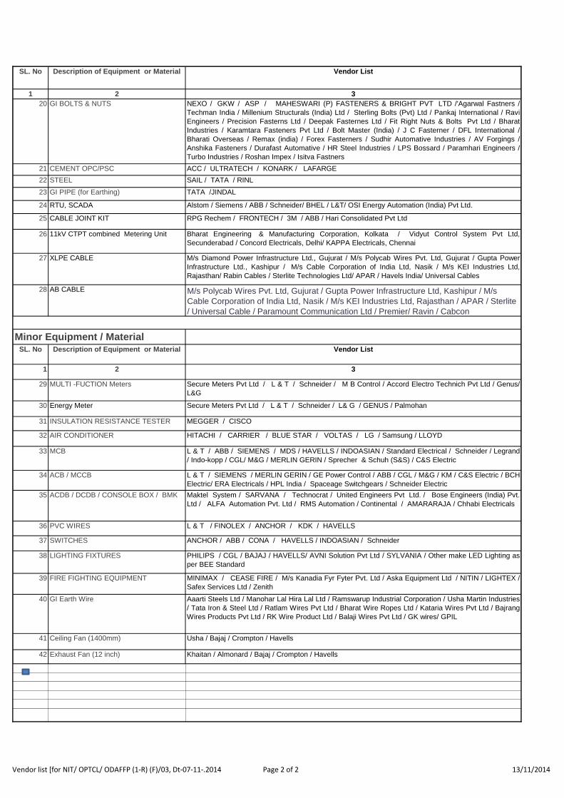
SL. No Description of Equipment or Material Vendor List
1 2 3
20 GI BOLTS & NUTS NEXO / GKW / ASP / MAHESWARI (P) FASTENERS & BRIGHT PVT LTD /'Agarwal Fastners /
Techman India / Millenium Structurals (India) Ltd / Sterling Bolts (Pvt) Ltd / Pankaj International / Ravi
Engineers / Precision Fasterns Ltd / Deepak Fasternes Ltd / Fit Right Nuts & Bolts Pvt Ltd / Bharat
Industries / Karamtara Fasteners Pvt Ltd / Bolt Master (India) / J C Fasterner / DFL International /
Bharati Overseas / Remax (india) / Forex Fasterners / Sudhir Automative Industries / AV Forgings /
Anshika Fasteners / Durafast Automative / HR Steel Industries / LPS Bossard / Paramhari Engineers /
Turbo Industries / Roshan Impex / Isitva Fastners
21 CEMENT OPC/PSC ACC / ULTRATECH / KONARK / LAFARGE
22 STEEL SAIL / TATA / RINL
23 GI PIPE (for Earthing) TATA /JINDAL
24 RTU, SCADA Alstom / Siemens / ABB / Schneider/ BHEL / L&T/ OSI Energy Automation (India) Pvt Ltd.
25 CABLE JOINT KIT RPG Rechem / FRONTECH / 3M / ABB / Hari Consolidated Pvt Ltd
26 11kV CTPT combined Metering Unit Bharat Engineering & Manufacturing Corporation, Kolkata / Vidyut Control System Pvt Ltd,
Secunderabad / Concord Electricals, Delhi/ KAPPA Electricals, Chennai
27 XLPE CABLE M/s Diamond Power Infrastructure Ltd., Gujurat / M/s Polycab Wires Pvt. Ltd, Gujurat / Gupta Power
Infrastructure Ltd., Kashipur / M/s Cable Corporation of India Ltd, Nasik / M/s KEI Industries Ltd,
Rajasthan/ Rabin Cables / Sterlite Technologies Ltd/ APAR / Havels India/ Universal Cables
28 AB CABLE M/s Polycab Wires Pvt. Ltd, Gujurat / Gupta Power Infrastructure Ltd, Kashipur / M/s
Cable Corporation of India Ltd, Nasik / M/s KEI Industries Ltd, Rajasthan / APAR / Sterlite
/ Universal Cable / Paramount Communication Ltd / Premier/ Ravin / Cabcon
SL. No Description of Equipment or Material Vendor List
1 2 3
29 MULTI -FUCTION Meters Secure Meters Pvt Ltd / L & T / Schneider / M B Control / Accord Electro Technich Pvt Ltd / Genus/
L&G
30 Energy Meter Secure Meters Pvt Ltd / L & T / Schneider / L& G / GENUS / Palmohan
31 INSULATION RESISTANCE TESTER MEGGER / CISCO
32 AIR CONDITIONER HITACHI / CARRIER / BLUE STAR / VOLTAS / LG / Samsung / LLOYD
33 MCB L & T / ABB / SIEMENS / MDS / HAVELLS / INDOASIAN / Standard Electrical / Schneider / Legrand
/ Indo-kopp / CGL/ M&G / MERLIN GERIN / Sprecher & Schuh (S&S) / C&S Electric
34 ACB / MCCB L & T / SIEMENS / MERLIN GERIN / GE Power Control / ABB / CGL / M&G / KM / C&S Electric / BCH
Electric/ ERA Electricals / HPL India / Spaceage Switchgears / Schneider Electric
35 ACDB / DCDB / CONSOLE BOX / BMK Maktel System / SARVANA / Technocrat / United Engineers Pvt Ltd. / Bose Engineers (India) Pvt.
Ltd / ALFA Automation Pvt. Ltd / RMS Automation / Continental / AMARARAJA / Chhabi Electricals
36 PVC WIRES L & T / FINOLEX / ANCHOR / KDK / HAVELLS
37 SWITCHES ANCHOR / ABB / CONA / HAVELLS / INDOASIAN / Schneider
38 LIGHTING FIXTURES PHILIPS / CGL / BAJAJ / HAVELLS/ AVNI Solution Pvt Ltd / SYLVANIA / Other make LED Lighting as
per BEE Standard
39 FIRE FIGHTING EQUIPMENT MINIMAX / CEASE FIRE / M/s Kanadia Fyr Fyter Pvt. Ltd / Aska Equipment Ltd / NITIN / LIGHTEX /
Safex Services Ltd / Zenith
40 GI Earth Wire Aaarti Steels Ltd / Manohar Lal Hira Lal Ltd / Ramswarup Industrial Corporation / Usha Martin Industries
/ Tata Iron & Steel Ltd / Ratlam Wires Pvt Ltd / Bharat Wire Ropes Ltd / Kataria Wires Pvt Ltd / Bajrang
Wires Products Pvt Ltd / RK Wire Product Ltd / Balaji Wires Pvt Ltd / GK wires/ GPIL
41 Ceiling Fan (1400mm) Usha / Bajaj / Crompton / Havells
42 Exhaust Fan (12 inch) Khaitan / Almonard / Bajaj / Crompton / Havells
Minor Equipment / Material
Vendor list [for NIT/ OPTCL/ ODAFFP (1-R) (F)/03, Dt-07-11-.2014 Page 2 of 2 13/11/2014
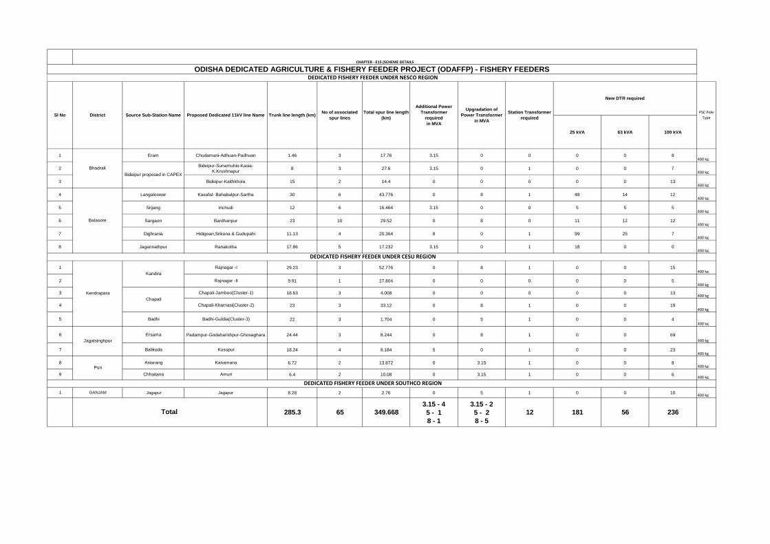
25 kVA 63 kVA 100 kVA
1 Eram Chudamani-Adhuan-Padhuan 1.46 3 17.76 3.15 0 0 0 0 8400 kg
2Bideipur-Sunamuhin-Kasia-
K.Krushnapur8 3 27.6 3.15 0 1 0 0 7
400 kg
3 Bideipur-Kaithkhola 15 2 14.4 0 0 0 0 0 13400 kg
4 Langaleswar Kasafal- Bahabalpur-Sartha 30 6 43.776 0 8 1 48 14 12400 kg
5 Srijang Inchudi 12 6 16.464 3.15 0 0 5 5 5400 kg
6 Sargaon Bardhanpur 23 10 29.52 0 8 0 11 12 12400 kg
7 Dighrania Hidigoan,Srikona & Gudupahi 11.13 4 20.364 8 0 1 99 25 7400 kg
8 Jagannathpur Ranakotha 17.86 5 17.232 3.15 0 1 18 0 0400 kg
1 Rajnagar -I 29.23 3 52.776 0 8 1 0 0 15400 kg
2 Rajnagar -II 9.91 1 27.804 0 0 0 0 0 5400 kg
3 Chapali-Jamboo(Cluster-1) 18.63 3 4.008 0 0 0 0 0 13400 kg
4 Chapali-Kharnasi(Cluster-2) 23 3 33.12 0 8 1 0 0 19400 kg
5 Badhi Badhi-Guldia(Cluster-3) 22 3 1.704 0 5 1 0 0 4400 kg
6 Ersama Padampur-Godaharishpur-Ghosaghara 24.44 3 8.244 0 8 1 0 0 69
400 kg
7 Balikuda Kusupur 18.24 4 8.184 5 0 1 0 0 23400 kg
8 Astarang Kanamana 6.72 2 13.872 0 3.15 1 0 0 8400 kg
9 Chhaitana Amuri 6.4 2 10.08 0 3.15 1 0 0 6400 kg
1 GANJAM Jagapur Jagapur 8.28 2 2.76 0 5 1 0 0 10400 kg
285.3 65 349.668
3.15 - 4
5 - 1
8 - 1
3.15 - 2
5 - 2
8 - 5
12 181 56 236
CHAPTER - E15 (SCHEME DETAILS
PSC Pole
Type
Bhadrak
Bideipur proposed in CAPEX
Puri
DEDICATED FISHERY FEEDER UNDER SOUTHCO REGION
Total
Balasore
DEDICATED FISHERY FEEDER UNDER CESU REGION
Kendrapara
Kandira
Chapali
Jagatsinghpur
ODISHA DEDICATED AGRICULTURE & FISHERY FEEDER PROJECT (ODAFFP) - FISHERY FEEDERS DEDICATED FISHERY FEEDER UNDER NESCO REGION
Sl No District Source Sub-Station Name Proposed Dedicated 11kV line Name Trunk line length (km)No of associated
spur lines
Total spur line length
(km)
Additional Power
Transformer
required
in MVA
Upgradation of
Power Transformer
in MVA
Station Transformer
required
New DTR required