SPECIFICATION FOR IDENTIFICATION MARKING OF PARTS S 3006
13
Specification S-3006 Release Date: 2/22/88 Specification for Identification Marking of Parts This document is the property of Tactair Fluid Controls Inc., and represents a proprietary article and proprietary information to which Tactair Fluid Controls Inc. retains the exclusive right of use and/or manufacture and/or sale. This document may not be reproduced without the written permission of Tactair Fluid Controls Inc. The information contained herein could be subject to U.S. Export laws and, if classified as a military item, is controlled by the US International Traffic in Arms Regulation (ITAR) 22 CFR Part 120-130. This document is protected as an unpublished work under the U.S. Copyright Act of 1976, as well as under other pertinent domestic and international intellectual property provisions. All rights reserved. Page 1 of 13 SPECIFICATION FOR IDENTIFICATION MARKING OF PARTS S-3006
Transcript of SPECIFICATION FOR IDENTIFICATION MARKING OF PARTS S 3006

Specification
S-3006
Release Date: 2/22/88 Specification for Identification Marking of Parts
This document is the property of Tactair Fluid Controls Inc., and represents a proprietary article and proprietary information to which Tactair Fluid Controls Inc. retains the exclusive right of use and/or manufacture and/or sale. This document may not be reproduced without the written permission of Tactair Fluid Controls Inc. The information contained herein could be subject to U.S. Export laws and, if classified as a military item, is controlled by the US International Traffic in Arms Regulation (ITAR) 22 CFR Part 120-130. This document is protected as an unpublished work under the U.S. Copyright Act of 1976, as well as under other pertinent domestic and international intellectual property provisions. All rights reserved.
Page 1 of 13
SPECIFICATION
FOR
IDENTIFICATION MARKING OF PARTS
S-3006

Specification
S-3006
Release Date: 2/22/88 Specification for Identification Marking of Parts
Refer to Page 1 for Limited Rights and Distribution Statements
Page 2 of 13
Record of Revisions
Revision Date Description Approved
By
- 02/22/88 Released – See DCN 10721 L.M.
A 05/22/89 Revised – See DCN 11669 T.N.
B 06/03/93 Revised – See DCN 19030 T.N.
C 07/26/96 Retyped – Added Table of Contents & Rev. Sheet- See EO 20765.
L.R.
D 04/29/05 See ECN 18183 BL
E 01/24/14 REVISED PER CN-001503 GF
F 05/22/14 REVISED PER CN-002094 DWV
G 09/16/15 REVISED PER CN-004198 SM

Specification
S-3006
Release Date: 2/22/88 Specification for Identification Marking of Parts
Refer to Page 1 for Limited Rights and Distribution Statements
Page 3 of 13
Table of Contents
1. Scope .................................................................................................................................................. 4
2. Reference Documents ....................................................................................................................... 4
3. General Requirements ...................................................................................................................... 4
4. Marking Procedure and Requirements ........................................................................................... 8

Specification
S-3006
Release Date: 2/22/88 Specification for Identification Marking of Parts
Refer to Page 1 for Limited Rights and Distribution Statements
Page 4 of 13
1. Scope
1.1 This specification establishes the method and procedures required for the identification marking of parts for Young & Franklin Inc. /Tactair Fluid Controls Inc.
1.2 This specification fulfills the minimum requirements of existing government specifications covering this subject to the extent noted herein.
1.3 This specification becomes a part of the detail drawings on which it is specified. If the requirements of this specification conflict with those of the detail drawing, the drawing shall have precedence.
2. Reference Documents
2.1 The following specifications form a part of this document to the extent noted herein.
2.1.1 Federal Specifications
PPT-T-60 Tape, pressure sensitive adhesive, waterproof, for packaging
PPT-T-76 Tape, pressure sensitive adhesive, paper
TT-I-1795 Ink, marking stencil, opaque (porous surfaces and non-porous surfaces)
2.1.2 Military Specifications and Standards
MIL-STD-129 Marking for Shipment and Storage
MIL-STD-130 Identification Marking of U.S. Military Property
MIL-STD-43553 Ink, Marking, Epoxy Base
2.1.3 Industry Specifications and Standards
2.1.3.1 AS478 Identification Marking Methods
3. General Requirements
The following data governs the requirements for the established classes or marking:
3.1 Classes
Class 1- Integral markings, castings, forgings, etc.
Class 2- Steel Stamping
Class 3- Electric Pencil
Class 4- Electro-Chemical Process
Class 5- Rubber Stamping
Class 6- Tape and/or Labels
Class 7- Tagging
Class 8- Bag and Tag
Class 9- Ink Etch
Class 10- Miscellaneous
Class 11- Engraving, Milled
Class 12- Laser Etching
3.2 Definitions
For the purpose of this specification the following definitions shall apply:
3.2.1 Identification

Specification
S-3006
Release Date: 2/22/88 Specification for Identification Marking of Parts
Refer to Page 1 for Limited Rights and Distribution Statements
Page 5 of 13
Any marking applied to an item or it’s packable for the purpose of engineering, manufacturing or inspection control, e.g., part number, source code, inspection marking.
3.2.2 Item
An article used in this specification to relate to a part, assembly or equipment.
3.2.3 Package
The smallest enclosure into which an item(s) is placed for protection during storage or shipment.
3.2.4 Permanent Marking
3.2.4.1 Marking which will ensure identification during the normal service life of the item.
3.2.4.2 Permanent markings shall not be applied on surfaces which have been chemically processed, painted, or plated unless the marking will be legible and the minimum requirements of the surface treatment process are maintained or restored.
3.2.5 Temporary Marking
Marking which will ensure identification during ordinary handling and storage or items prior to assembly and use. Under certain conditions of service these markings may exhibit the characteristics or permanent markings.
3.3 Part and Assembly Marking
The class of marking shall be as specified on the engineering drawing. The part number when placed on the part or assembly shall include the FSCM No. and change letter following or below the part number, except on nameplates. Any other markings specified on the engineering drawing shall be included. (Example: 70236-39C39XXXAX)
3.3.1 Parts shall be individually marked with the applicable identifying number, when space permits, except the following:
3.3.1.1 Commonly known commercial parts which present no identification problem.
3.3.1.2 Parts in subassemblies and assemblies which are not normally subject to disassembly or repair.
3.4 Marking Location
Location of marking on items shall be as specified on the engineering drawing in accordance with the following, as applicable.
3.4.1
This symbol, or a local note, indicates a general location for marking.
3.4.2
This symbol, or a local note, indicated a pad location for marking.
3.4.3
This symbol, or a local note, indicates the location for integral marking cast, forged or molded parts.
3.4.4
This symbol, or a local note, indicates a specific area within which markings shall be confined.
3.4.5
Symbol Size: The actual size of the symbols noted shall be in accordance with this example.

Specification
S-3006
Release Date: 2/22/88 Specification for Identification Marking of Parts
Refer to Page 1 for Limited Rights and Distribution Statements
Page 6 of 13
3.4.6 When location and size of letters and numbers are critical, they may be dimensioned in place. A heavy dash outline may be used to represent the identification specified in the general notes.
3.5 Drawing Notes
Each drawing, as required, shall carry a note referencing marking applied in accordance with this specification. It shall also note, or show location and size of marking, if location and size are critical. The general notes and drawing designations shall be made in accordance with the following examples:
3.5.1 General Location
General Note
Apply part number per S-3006
Class 4
On Drawing
3.5.2 Pad Location
General Note
Apply part number per S-3006
Class 1, depressed .015 maximum
On Drawing
3.5.3 Integral Marking Location
General Note
Apply part number per S-3006
Class 1, raised .005 - .010
On Drawing
3.5.4 Engineering Drawings shall completely define where and how each item is to be identified by means of local notes and reference to this specification as shown above.
3.5.5 Careful consideration shall be given to the method of marking and where it shall be applied. The method selected shall not deleteriously affect the part and must be plainly visible after assembly whenever possible.
3.5.6 Parts too small to be marked shall be placed in a container and the container shall be marked or tagged with the applicable identification information.
3.6 Style and Size Marking

Specification
S-3006
Release Date: 2/22/88 Specification for Identification Marking of Parts
Refer to Page 1 for Limited Rights and Distribution Statements
Page 7 of 13
Unless specifically noted on the engineering drawings, the size of numbers and letters used for part numbers and other identification shall be selected with the following requirements in mind:
3.6.1 All markings shall be of such a size as to be clearly legible.
3.6.2 Size of markings shall be proportional to the size of the part or area to be marked.
3.6.3 The size of numerals and letters shall never be less than .06 inch high. Maximum size shall be proportional to the size of the part to be marked, but in no case shall exceed .38 inch.
3.6.4 Letters and numerals shall be without serifs (sans serif), such as Gothic or Futura capitals. Numerals shall be Arabic. Other characters shall be similar in appearance.
3.7 Altered parts
When commercially produced parts are altered, all old identification shall be removed or obliterated by an applicable means and replaced by new identification as specified on the drawing.
When all or a portion of a part number is inadvertently removed or obliterated it shall be the responsibility of quality assurance to ensure that the part is re-identified.
3.8 Assembly Marking
The notation “assy” shall be marked as a prefix to the subassembly or assembly identifying part number to differentiate such numbers from part identifying numbers (Example: 70236ASSY39C39XXXAX).
3.8.1 When assemblies or subassemblies cannot be physically marked with any of the methods specified herein, the appropriate information shall be marked on identification tags according to the Class 7 or Class 8 requirements noted herein. The tags shall be secure ly attached to uninstalled assemblies or subassemblies furnished as spares, etc.
3.9 Matched Sets or Spares
3.9.1 Each part of a matched set or pair shall be individually identified be a part number as specified on the engineering drawing.
3.9.2 Matched sets or pairs shall be securely fastened together, or bagged or packaged in a suitable container.
3.9.3 “Matched set (or pair) – DO NOT issue separately” followed by the part number of the assembly and any applicable inspection marks shall be stamped on a tag fastened to the parts, or placed in the container/bag.
3.9.4 Containers (boxes, vials, etc.) shall be closed securely and marked with the information noted above.
3.10 Inspection Marking
3.10.1 Unless otherwise specified, the method of applying inspection marks shall be the same as for part numbering specified on the engineering drawing. On casting or forgings inspection marking shall meet the marking requirements of the next assembly drawing.
3.10.2 Inspection marking shall be placed adjacent to the part number unless the drawing designated a specific area for inspection marks.
3.10.3 The size of the inspection marks shall be such that they are clearly legible and proportional to the size of the part or area to be marked.
3.10.4 When all or a part of an inspection mark is removed or obliterated by any means, it shall be the responsibly of the inspection departments to insure that the mark is restored before the part leaves the manufacturing area.
3.11 Fabrication Markings
3.11.1 Marking that aids is the fabrication or processing of parts shall be held to a practical minimum.
3.11.2 Unless the marking is in an area where it will remove by subsequent fabrication operations it shall be of a temporary nature and easily removable.

Specification
S-3006
Release Date: 2/22/88 Specification for Identification Marking of Parts
Refer to Page 1 for Limited Rights and Distribution Statements
Page 8 of 13
3.11.3 The following methods of making are applicable to fabrication marking: Class 2, 3, 5 and 7 except that methods 2 and 3 shall not be used on steel parts harder than RC 38.
3.12 Marking Materials
3.12.1 Approval of marking materials and sources thereof will be the responsibility of the Quality Assurance Department. Marking materials and sources shown in Tables 1 and 2 herein are not to be construed as an approved source list, but are provided for information only. Equivalent or better products shall be considered acceptable providing that the requirements of this specification are met.
4. Marking Procedure and Requirements
4.1 Class 1 Marking – Casting, Forging and Moldings
4.1.1 All casting, forgings and molding shall be identified by appropriate raised or indented numbers, the location of which shall be as specified on the engineering drawing.
4.2 Class 2 Marking – Steel Stamping
4.2.1 Steel stamping may be applied by hand or machine methods providing that the following requirements are met:
4.2.1.1 Steel stamping shall not causing distortion of the material or disfiguration of the reverse side.
4.2.1.2 Intersecting surfaces of stamps used for steel stamping shall have all sharp corners reduced to radius of not less than .005 inch.
4.2.1.3 Steel stamping shall be accomplished prior to protective surface treatment such as, plating, anodizing, painting, etc.
4.3 Class 3 – Electric Pencil (Vibroetch and Electric Arc)
4.3.1 Electric pencil marking may be applied by either hand or machine methods, providing that the following requirements are met.
4.3.1.1 The penetration of the electric pencil marking shall be only deep enough to be legible, but never greater than .004 inch. Good penetration is especially required when the part is to be subjected to surface treatment such as plating, etc.
4.3.1.2 Electric pencil marking of parts shall be accomplished prior to protective surface treatment such as plating, anodizing, painting, etc.
4.4 Class 4 – Electrochemical Marking
4.4.1 The area to be electroetch marked shall be solvent wiped to remove dirt, grease, oil or other surface contamination that would prevent clear, sharp marking or cause the stencil to become clogged.
4.4.2 Electroetch marking shall be applied prior to such surface treatment as anodizing, phosphatizing, Dow 7, etc. and after plating or black oxide treatment.
4.4.3 Magnesium alloys and porous surfaces of other metals, produced by acid picking or sand or vapor blasting, shall have a thin film of oil applied before marking.
4.4.4 The felt pad shall be moistened with the electrolyte solution specified in Table 1, or equivalent.
4.4.5 Electrolyte pads shall be used for more than one type of electrolyte.
4.4.6 The pad shall be saturated with electrolyte but shall not be so wet that excess solution squeezes out during application.
4.4.7 It is not necessary to wet the pad before each use, but only when marking becomes less distinct.
4.4.8 Test marks shall be made on scrap material before marking production parts to adjust current and marking time in order to produce the most distinct and sharp marking possible.
4.4.9 The stencil shall be placed on the part, in the area to be marked or on the electrolyte pad and held or fastened firmly in place.

Specification
S-3006
Release Date: 2/22/88 Specification for Identification Marking of Parts
Refer to Page 1 for Limited Rights and Distribution Statements
Page 9 of 13
4.4.10 With the AC-DC switch set as indicated in Table 1, the electrolyte pad and stencil shall be pressed against the part for approximately 2 or 3 seconds, or for the time derived from the electrolyte manufactures recommendations, whichever is necessary to produce clear markings.
4.4.11 The electrolyte solution or pad shall not touch the part except through the cut in the stencil.
4.4.12 On curved surfaces the pad shall be rolled over the cut area of the stencil.
4.4.13 After marking, the marked area shall be thoroughly cleaned with electroetch (or equivalent) cleaner and lint free tissue to prevent corrosion, see Table 1 for applicable cleaning solutions.
4.5 Class 5 – Rubber Stamping
4.5.1 Rubber stamp identification shall be applied only on clean, dry surfaces. Oil, grease, dirt, or other contamination shall be removed from the surface by solvent wiping.
4.5.2 All rubber stamped identification and inspection marking shall be clear and legible.
4.5.3 Unless the color of ink is specified on the drawing, an ink having a high degree of contrast with the background shall be selected to provide the greatest legibility feasible.
4.5.4 Only permanent type marking ink shall be used for part numbering and inspection marking.
4.5.5 Marking inks and their usage are shown in Table 2.
4.5.6 Parts requiring rubber stamp marking shall be tagged during processing and shall be re-identified, as necessary, after processing.
4.5.7 Rubber stamping shall not be applied on any painted part until the paint has dried for one hour, or is no longer tacky; whichever is the longer period of time.
4.6 Class 6 – Taping
4.6.1 Tape or label, self-adhesive or solvent activated adhesive backed, to be used for permanent identification purposes shall be as specified on the engineering drawing. For temporary identification, any applicable tape may be used.
4.6.2 Tape shall be applied only to clean, dry surfaces. Grease, oil, dirt or other contamination shall be removed from the surface by solvent cleaning.
4.6.2.1 Care shall be taken not to touch the cleaned surface or the adhesive backing before application of the tape.
4.6.2.2 The tape shall be applied to the surface noted on the drawing and pressed firmly in place.
4.6.2.3 On cylindrical shapes, such as turbine, hose, etc., the tape shall overlap a minimum of one-half inch or half the circumference, whichever is the lesser.
4.7 Class 7- Tagging
4.7.1 Permanent Identification – Tag Only
Unless otherwise specified on the engineering drawing or as noted in the following, permanent identification tags may be of paper, cloth or metal and may be of any convenient size. Recommended quantities of parts to be tagged are shown in Table 4.
4.7.2 Paper and cloth tags shall be rubber stamped as specified in Paragraph 4.5 and shall be attached by means of string.
4.7.3 Metal tags shall be marked as specified in Paragraph 4.2, and shall be attached by wire as specified in Table 3.
4.7.4 When parts are permanently tagged prior to heat treating, cleaning, pickling, plating or other chemical treatments, the use of metal tags and wire shall be required.
4.7.5 When metal tags are required, the materials used for tags and wire shall be as specified in Table 3.

Specification
S-3006
Release Date: 2/22/88 Specification for Identification Marking of Parts
Refer to Page 1 for Limited Rights and Distribution Statements
Page 10 of 13
4.7.5.1 Careful consideration shall be given to the environment to which the tag and wire will be exposed in order to assure proper selection of tag and wire material.
4.8 Class 8- Bag and Tag
4.8.1 Parts shall be placed in envelopes or plastic bags or containers, either individually or in convenient numbers, such as the number of parts required per unit or next assembly. See Table 4.
4.8.2 Items having finishes finer than 125 micro-inches, which would deleteriously affect performance of end items if they are nicked, gouged or distorted, etc., shall be individually packaged.
4.8.3 Paper envelope shall be sealed after the identification and inspection markings are rubber stamped on the outside.
4.8.4 Plastic bags shall be tagged as specified in Paragraph 4.7 and the top of the bag shall be securely tied with the string or wire used to attach the tag; or the tag shall be placed inside the bag, in which case the bag shall be closed by sealing or folding and taping or stapling.
4.8.5 Plastic containers shall be sealed with a label type tag or tape on which the required identification is rubber stamped, or the stamped tag shall be placed inside the container is such a manner that the information shown there on is visible from the outside in the case of clear plastic containers.
4.9 Class 9- Ink Etch
4.9.1 Ink etching provides a method of marking whereby the characters are formed by a suitable etching ink applied by means of a rubber stamp. Self-neutralizing ink shall be used in all cases where ink etch is specified.
4.10 Class 10- Miscellaneous
4.10.1 This type of marking includes any method of identification or marking not otherwise covered by this specification or marking not otherwise covered by this specification, e.g., decalcomania, silk screen, stencil, etc.
4.10.2 Miscellaneous marking shall be performed as specified on the engineering drawing.
4.11 Class 11- Engraving, Milled
4.11.1 Machined, engraved marking shall meet the following requirements unless otherwise specified on the part drawing:
4.11.1.1 Engraving depth shall not exceed .010 and be .002 min.
4.11.1.2 Engraving shall be performed with a .005 R min tool.
4.11.1.3 Engraving shall be performed prior to protective surface treatment such as plating, anodizing, painting, etc.
4.12 Class 12-Laser
4.12.1 Characters are produced by displacing material with a laser beam. Depth is controlled by varying the pulse rate of the beam, the speed of advance, the focus and the power.
4.12.2 Marking shall conform to the requirements of AS478 par. 4.1.15. Unless otherwise specified method 15B1 shall be used. Unless otherwise specified the depth ranges as defined by Table 1 of AS478 shall take precedent.
4.12.3 Laser marking can be performed either pre- or post-protective finish treatment application. If required or specified the protective finish treatment can be touched-up using standard procedures and materials. For example, Alodine 120 Kit (QPL-81706 materials) for anodized surfaces.
4.13 Serialization Inspection
4.13.1 Serialization may be inspected for letter height, depth and legibility. These aspects of the serialization shall not be taken into consideration when measuring the size or form of the surface the serialization is placed on.
Specification
S-3006
Release Date: 2/22/88 Specification for Identification Marking of Parts
Refer to Page 1 for Limited Rights and Distribution Statements
Page 11 of 13
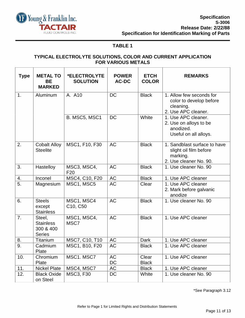
TABLE 1
TYPICAL ELECTROLYTE SOLUTIONS, COLOR AND CURRENT APPLICATION FOR VARIOUS METALS
*See Paragraph 3.12
Type
METAL TO
BE MARKED
*ELECTROLYTE
SOLUTION
POWER AC-DC
ETCH
COLOR
REMARKS
1. Aluminum A. A10
DC
Black
1. Allow few seconds for color to develop before cleaning. 2. Use APC cleaner.
B. MSC5, MSC1 DC White 1. Use APC cleaner. 2. Use on alloys to be anodized. Useful on all alloys.
2. Cobalt Alloy Steelite
MSC1, F10, F30 AC Black 1. Sandblast surface to have slight oil film before marking. 2. Use cleaner No. 90.
3. Hastelloy MSC3, MSC4, F20
AC Black 1. Use cleaner No. 90
4. Inconel MSC4, C10, F20 AC Black 1. Use APC cleaner
5. Magnesium MSC1, MSC5 AC Clear 1. Use APC cleaner 2. Mark before galvanic anodize
6. Steels except Stainless
MSC1, MSC4 C10, C50
AC Black 1. Use cleaner No. 90
7. Steel, Stainless 300 & 400 Series
MSC1, MSC4, MSC7
AC Black 1. Use APC cleaner
8. Titanium MSC7, C10, T10 AC Dark 1. Use APC cleaner
9. Cadmium Plate
MSC1, B10, F20 AC Black 1. Use APC cleaner
10. Chromium Plate
MSC1. MSC7 AC DC
Clear Black
1. Use APC cleaner
11. Nickel Plate MSC4, MSC7 AC Black 1. Use APC cleaner
12. Black Oxide on Steel
MSC3, F30 DC White 1. Use cleaner No. 90

Specification
S-3006
Release Date: 2/22/88 Specification for Identification Marking of Parts
Refer to Page 1 for Limited Rights and Distribution Statements
Page 12 of 13
TABLE 2
* Ref. Paragraph 3.12 * Marking Inks
TYPE INK
CODE INDENTIFICATION
RECOMMENDED USAGE
1. BLACK INKS
A. 73X, Black Independent Ink Co. Gardena, CA
12744 Permanent marking of metal and non-metal
B. Drimarquette No. 480 Sylvester Supply Co. Los Angeles, CA
Permanent marking of metals only.
C. 977-9 (HS915)
American Marking Systems 1017 Paulison Avenue Clifton, NJ
Permanent non-corrosive marking.
2. WHITE INKS
A. 73X, White 12744 Permanent marking of metals and non-metals.
Independent Ink Co. Gardena, CA
C. M-9-N w/catalyst A Dexter, HYSOL Industry, CA
Permanent marking of metal and non-metals.

Specification
S-3006
Release Date: 2/22/88 Specification for Identification Marking of Parts
Refer to Page 1 for Limited Rights and Distribution Statements
Page 13 of 13
TABLE 3
METAL TAG AND WIRE COMBINATIONS
PART MATERIAL
TAG
WIRE A. Magnesium
Magnesium
Pure Aluminum
B. Aluminum
Aluminum
Aluminum
C. Carbon and low Alloy Steels
Mild Steel or Stainless Steel
Mild Steel or Stainless Steel
D. All others
Stainless Steel
Stainless Steel
TABLE 4
RECOMMENDED TAG QUANITY
No. of Parts 5-100 100-500 50-100 Over 1M
No. of Tags (Percent
20% 10% 5% 50 Max.