SPECIFICATION ELECTROMAGNETIC INTERFERENCE …
242
SL-E-0002 - BOOK 3 VOLUME 1 SPACE SHUTTLE SPECIFICATION ELECTROMAGNETIC INTERFERENCE CHARACTERISTICS, REQUIREMENTS FOR EQUIPMENT BOOK 3 NEW OR MODIFIED EQUIPMENT AUGUST 10, 2001 Lyndon B. Johnson Space Center Houston, Texas 77058 National Aeronautics and Space Administration Downloaded from http://www.everyspec.com
Transcript of SPECIFICATION ELECTROMAGNETIC INTERFERENCE …

SL-E-0002 - BOOK 3VOLUME 1
SPACE SHUTTLE
SPECIFICATION
ELECTROMAGNETIC INTERFERENCECHARACTERISTICS,
REQUIREMENTS FOR EQUIPMENT
BOOK 3
NEW OR MODIFIED EQUIPMENT
AUGUST 10, 2001
Lyndon B. Johnson Space CenterHouston, Texas 77058
National Aeronautics andSpace Administration
Downloaded from http://www.everyspec.com

Downloaded from http://www.everyspec.com

REVISION LOG
REVLTR
CHANGENO DESCRIPTION DATE
BASELINE ISSUE (Reference PRCBD S061680, dated6/25/01) also includes CAR S061680.
08/10/01
SL-E-0002 - Book 3, Volume 1
Downloaded from http://www.everyspec.com

Downloaded from http://www.everyspec.com

SL-E-0002 - Space ShuttleSpecification
Electromagnetic InterferenceCharacteristics, Requirements for Equipment
Book 3 - New or Modified Equipment
*Baseline Issue (Reference PRCBD No. S061680, dated 6/25/01 and CAR S061680,dated 8/2/01)
LIST OF EFFECTIVE PAGES
August 10, 2001
The current status of all pages in this document is as shown below:
Page No. Change No. PRCBD No. Date
i - xiv Baseline * August 10, 20011-1 - 1-2 Baseline * August 10, 20012-1 - 2-6 Baseline * August 10, 20013-1 - 3-2 Baseline * August 10, 20014-1 - 4-28 Baseline * August 10, 20015-1 - 5-88 Baseline * August 10, 20016-1 - 6-2 Baseline * August 10, 2001A-1 - A-6 Baseline * August 10, 2001B-1 - B-88 Baseline * August 10, 2001
Downloaded from http://www.everyspec.com

Downloaded from http://www.everyspec.com

SL-E-0002 - BOOK 3VOLUME 1
SPACE SHUTTLE
SPECIFICATIONELECTROMAGNETIC INTERFERENCE
CHARACTERISTICS,REQUIREMENTS FOR EQUIPMENT
BOOK 3
NEW OR MODIFIED EQUIPMENT
Downloaded from http://www.everyspec.com

iiSL-E-0002 - Book 3, Volume 1Baseline
THIS PAGE INTENTIONALLY LEFT BLANK
Downloaded from http://www.everyspec.com

SL-E-0002 - Book 3, Volume 1Baseline
iii
FOREWORD
Efficient management of the Space Shuttle Program (SSP) dictates that effectivecontrol of program activities be established. Requirements, directives, procedures,interface agreements, and system capabilities shall be documented, baselined, andsubsequently controlled by SSP management.
Program requirements controlled by the Manager, Space Shuttle Program, aredocumented in, attached to, or referenced from Volume I through XVIII of NSTS 07700.
SL-E-0002 contains three books applicable as defined below:
c. Book 1 is applicable to all hardware procurements prior to February 11, 1993.
d. Book 2 is applicable to all hardware procurements with an Authority to Proceed(ATP) after February 11, 1993 and before May 7, 2001.
e. Book 3 is applicable to all hardware procurements with an ATP on or after May 7, 2001.
For certifying modifications to hardware that was certified to the requirements contained ineither Book 1 or Book 2, the choice of using SL-E-0002 - Book 3 or using SL-E-0002 -Book 1 or Book 2, respectively, is left to the discretion of the affected element projectmanager.
This book of SL-E-0002 has been prepared specifically to tailor the requirements ofMIL-STD-461E, Requirements for the Control of Electromagnetic InterferenceCharacteristics of Subsystems and Equipment, to Space Shuttle equipment levelprocurements. MIL-STD-461E, and thus this book, incorporates test requirementspreviously contained in MIL-STD-462, Electromagnetic Interference Characteristics,Measurement of. MIL-STD-462 is a retired document.
All elements of the SSP must adhere to these baselined requirements. When it isconsidered by the Space Shuttle program element/project managers to be in the bestinterest of the SSP to change, waive or deviate from these requirements, an SSPChange Request (CR) shall be submitted to the Program Requirements Control Board(PRCB) Secretary. The CR must include a complete description of the change, waiveror deviation and the rationale to justify its consideration. All such requests will beprocessed in accordance with NSTS 07700, Volume IV - Book 1 and dispositioned bythe Manager, Space Shuttle Program, on a Space Shuttle PRCB Directive (PRCBD).
Downloaded from http://www.everyspec.com

SL-E-0002 - Book 3, Volume 1Baseline
iv
THIS PAGE INTENTIONALLY LEFT BLANK
Downloaded from http://www.everyspec.com

vSL-E-0002 - Book 3, Volume 1Baseline
1.0 INTRODUCTION 1-1. . . . . . . . . . . . . . . . . . . . . . . . . . . . . . . . . . . . . . . . . . . . . .
1.1 SCOPE 1-1. . . . . . . . . . . . . . . . . . . . . . . . . . . . . . . . . . . . . . . . . . . . . . . . . . . . . . . 1.1.1 Requirements 1-1. . . . . . . . . . . . . . . . . . . . . . . . . . . . . . . . . . . . . . . . . . . . . . . 1.1.2 Use 1-1. . . . . . . . . . . . . . . . . . . . . . . . . . . . . . . . . . . . . . . . . . . . . . . . . . . . . . . . 1.1.3 Applicability 1-2. . . . . . . . . . . . . . . . . . . . . . . . . . . . . . . . . . . . . . . . . . . . . . . . . 1.1.4 Structure 1-2. . . . . . . . . . . . . . . . . . . . . . . . . . . . . . . . . . . . . . . . . . . . . . . . . . .
1.2 EMISSION AND SUSCEPTIBILITY DESIGNATIONS 1-2. . . . . . . . . . . . . . .
2.0 APPLICABLE DOCUMENTS 2-1. . . . . . . . . . . . . . . . . . . . . . . . . . . . . . . . . . . .
2.2 ORDER OF PRECEDENCE 2-6. . . . . . . . . . . . . . . . . . . . . . . . . . . . . . . . . . . . .
3.0 DEFINITIONS 3-1. . . . . . . . . . . . . . . . . . . . . . . . . . . . . . . . . . . . . . . . . . . . . . . . .
3.1 EXTERNAL INSTALLATION 3-1. . . . . . . . . . . . . . . . . . . . . . . . . . . . . . . . . . . .
3.2 FLIGHT-LINE EQUIPMENT 3-1. . . . . . . . . . . . . . . . . . . . . . . . . . . . . . . . . . . . .
3.3 INTERNAL INSTALLATION 3-1. . . . . . . . . . . . . . . . . . . . . . . . . . . . . . . . . . . . .
3.4 METRIC UNITS 3-1. . . . . . . . . . . . . . . . . . . . . . . . . . . . . . . . . . . . . . . . . . . . . . . .
3.5 NON-DEVELOPMENTAL ITEM 3-1. . . . . . . . . . . . . . . . . . . . . . . . . . . . . . . . . .
3.6 SAFETY CRITICAL 3-1. . . . . . . . . . . . . . . . . . . . . . . . . . . . . . . . . . . . . . . . . . . .
3.7 TEST SETUP BOUNDARY 3-1. . . . . . . . . . . . . . . . . . . . . . . . . . . . . . . . . . . . .
4.0 GENERAL REQUIREMENTS 4-1. . . . . . . . . . . . . . . . . . . . . . . . . . . . . . . . . . .
4.1 APPLICATION OF SPECIFICATION 4-1. . . . . . . . . . . . . . . . . . . . . . . . . . . . . 4.1.1 Subsystems 4-3. . . . . . . . . . . . . . . . . . . . . . . . . . . . . . . . . . . . . . . . . . . . . . . . 4.1.2 Government Furnished Equipment (GFE) 4-3. . . . . . . . . . . . . . . . . . . . . . . 4.1.3 Commercial Off-the-Shelf (COTS) Equipment 4-3. . . . . . . . . . . . . . . . . . . 4.1.4 Other EMI Requirements 4-3. . . . . . . . . . . . . . . . . . . . . . . . . . . . . . . . . . . . . 4.1.5 Short-duration Interference 4-3. . . . . . . . . . . . . . . . . . . . . . . . . . . . . . . . . . . 4.1.6 Self-compatibility 4-4. . . . . . . . . . . . . . . . . . . . . . . . . . . . . . . . . . . . . . . . . . . .
4.2 DOCUMENTATION REQUIREMENTS 4-4. . . . . . . . . . . . . . . . . . . . . . . . . . . . 4.2.1 EMI Control Procedure 4-4. . . . . . . . . . . . . . . . . . . . . . . . . . . . . . . . . . . . . . . 4.2.2 EMI Test Procedures 4-5. . . . . . . . . . . . . . . . . . . . . . . . . . . . . . . . . . . . . . . . . 4.2.3 EMI Test Report (EMITR) 4-7. . . . . . . . . . . . . . . . . . . . . . . . . . . . . . . . . . . . .
4.3 VERIFICATION REQUIREMENTS 4-9. . . . . . . . . . . . . . . . . . . . . . . . . . . . . . . 4.3.1 Measurement Tolerances 4-9. . . . . . . . . . . . . . . . . . . . . . . . . . . . . . . . . . . . .
CONTENTS
SL-E-0002 - Book 3, Volume 1
Downloaded from http://www.everyspec.com

viSL-E-0002 - Book 3, Volume 1Baseline
4.3.2 Shielded Enclosures 4-10. . . . . . . . . . . . . . . . . . . . . . . . . . . . . . . . . . . . . . . . . 4.3.3 Other Test Sites 4-10. . . . . . . . . . . . . . . . . . . . . . . . . . . . . . . . . . . . . . . . . . . . . 4.3.4 Ambient Electromagnetic Level 4-11. . . . . . . . . . . . . . . . . . . . . . . . . . . . . . . . 4.3.5 Ground Plane 4-11. . . . . . . . . . . . . . . . . . . . . . . . . . . . . . . . . . . . . . . . . . . . . . . 4.3.6 Power Source Impedance 4-11. . . . . . . . . . . . . . . . . . . . . . . . . . . . . . . . . . . . 4.3.7 General Test Precautions 4-12. . . . . . . . . . . . . . . . . . . . . . . . . . . . . . . . . . . . . 4.3.8 EUT Test Configurations 4-13. . . . . . . . . . . . . . . . . . . . . . . . . . . . . . . . . . . . . . 4.3.9 Operation of EUT 4-15. . . . . . . . . . . . . . . . . . . . . . . . . . . . . . . . . . . . . . . . . . . . 4.3.10 Use of Measurement Equipment 4-16. . . . . . . . . . . . . . . . . . . . . . . . . . . . . . 4.3.11 Calibration of Measuring Equipment 4-20. . . . . . . . . . . . . . . . . . . . . . . . . . .
5.0 DETAILED REQUIREMENTS 5-1. . . . . . . . . . . . . . . . . . . . . . . . . . . . . . . . . . .
5.1 GENERAL 5-1. . . . . . . . . . . . . . . . . . . . . . . . . . . . . . . . . . . . . . . . . . . . . . . . . . . . 5.1.1 Units of Frequency Domain Measurements 5-1. . . . . . . . . . . . . . . . . . . . .
5.2 CE102, CONDUCTED EMISSIONS, POWER LEADS, 10 KILOHERTZ (kHz) TO 10 MEGAHERTZ (MHz) 5-2. . . . . . . . . . . . . .
5.2.1 CE102 Applicability 5-2. . . . . . . . . . . . . . . . . . . . . . . . . . . . . . . . . . . . . . . . . . 5.2.2 CE102 Limits 5-2. . . . . . . . . . . . . . . . . . . . . . . . . . . . . . . . . . . . . . . . . . . . . . . 5.2.3 CE102 Test Procedure 5-2. . . . . . . . . . . . . . . . . . . . . . . . . . . . . . . . . . . . . . .
5.3 CE106, CONDUCTED EMISSIONS, ANTENNA TERMINAL, 100 MHz TO 18 GHz 5-8. . . . . . . . . . . . . . . . . . . . . . . . . . . . . . . . . . . . . . . . .
5.3.1 CE106 Applicability 5-8. . . . . . . . . . . . . . . . . . . . . . . . . . . . . . . . . . . . . . . . . . 5.3.2 CE106 Limits 5-8. . . . . . . . . . . . . . . . . . . . . . . . . . . . . . . . . . . . . . . . . . . . . . . 5.3.3 CE106 Test Procedure 5-8. . . . . . . . . . . . . . . . . . . . . . . . . . . . . . . . . . . . . . .
5.4 CS101, CONDUCTED SUSCEPTIBILITY, POWER LEADS, 30 HERTZ (Hz) TO 150 kHz 5-16. . . . . . . . . . . . . . . . . . . . . . . . . . . . . . . . . .
5.4.1 CS101 Applicability 5-16. . . . . . . . . . . . . . . . . . . . . . . . . . . . . . . . . . . . . . . . . . 5.4.2 CS101 Limit 5-16. . . . . . . . . . . . . . . . . . . . . . . . . . . . . . . . . . . . . . . . . . . . . . . . 5.4.3 CS101 Test Procedure 5-16. . . . . . . . . . . . . . . . . . . . . . . . . . . . . . . . . . . . . . .
5.5 CS103, CONDUCTED SUSCEPTIBILITY, ANTENNA PORT,INTERMODULATION, 15 kHz TO 10 GHz 5-26. . . . . . . . . . . . . . . . . . . . . .
5.5.1 CS103 Applicability 5-26. . . . . . . . . . . . . . . . . . . . . . . . . . . . . . . . . . . . . . . . . . 5.5.2 CS103 Limit 5-26. . . . . . . . . . . . . . . . . . . . . . . . . . . . . . . . . . . . . . . . . . . . . . . . 5.5.3 CS103 Test Procedures 5-26. . . . . . . . . . . . . . . . . . . . . . . . . . . . . . . . . . . . . .
5.6 CS104, CONDUCTED SUSCEPTIBILITY, ANTENNA PORT, REJECTION OF UNDESIRED SIGNALS, 30 Hz TO 18 GHz 5-26. . . . . .
5.6.1 CS104 Applicability 5-26. . . . . . . . . . . . . . . . . . . . . . . . . . . . . . . . . . . . . . . . . . 5.6.2 CS104 Limit 5-26. . . . . . . . . . . . . . . . . . . . . . . . . . . . . . . . . . . . . . . . . . . . . . . . 5.6.3 CS104 Test Procedures 5-27. . . . . . . . . . . . . . . . . . . . . . . . . . . . . . . . . . . . . .
CONTENTS
SL-E-0002 - Book 3, Volume 1
Downloaded from http://www.everyspec.com

viiSL-E-0002 - Book 3, Volume 1Baseline
5.7 CS106, CONDUCTED SUSCEPTIBILITY, ANTENNA PORT, CROSS MODULATION, 30 Hz TO 18 GHz 5-27. . . . . . . . . . . . . . . . . . . . .
5.7.1 CS105 Applicability 5-27. . . . . . . . . . . . . . . . . . . . . . . . . . . . . . . . . . . . . . . . . . 5.7.2 CS105 Limit 5-27. . . . . . . . . . . . . . . . . . . . . . . . . . . . . . . . . . . . . . . . . . . . . . . . 5.7.3 CS105 Test Procedures 5-27. . . . . . . . . . . . . . . . . . . . . . . . . . . . . . . . . . . . . .
5.8 CS106, CONDUCTED SUSCEPTIBILITY, POWER-LINE SWITCHING TRANSIENTS 5-27. . . . . . . . . . . . . . . . . . . . . . . . . . . . . . . . . . .
5.8.1 CS106 Applicability 5-27. . . . . . . . . . . . . . . . . . . . . . . . . . . . . . . . . . . . . . . . . . 5.8.2 CS106 Limit 5-28. . . . . . . . . . . . . . . . . . . . . . . . . . . . . . . . . . . . . . . . . . . . . . . . 5.8.3 CS106 Test Procedures 5-28. . . . . . . . . . . . . . . . . . . . . . . . . . . . . . . . . . . . . .
5.9 CS114, CONDUCTED SUSCEPTIBILITY, BULK CABLE INJECTION, 10 kHz TO 200 MHz 5-32. . . . . . . . . . . . . . . . . . . . . . . . . . . . .
5.9.1 CS114 Applicability 5-32. . . . . . . . . . . . . . . . . . . . . . . . . . . . . . . . . . . . . . . . . . 5.9.2 CS114 Limit 5-32. . . . . . . . . . . . . . . . . . . . . . . . . . . . . . . . . . . . . . . . . . . . . . . . . 5.9.3 CS114 Test Procedures 5-32. . . . . . . . . . . . . . . . . . . . . . . . . . . . . . . . . . . . . .
5.10 CS116, CONDUCTED SUSCEPTIBILITY, DAMPED SINUSOIDALTRANSIENTS, CABLES AND POWER LEADS, 10 kHz TO 10 MHz 5-40. . . . . . . . . . . . . . . . . . . . . . . . . . . . . . . . . . . . . . . . . . . . . . . . . . . .
5.10.1 CS116 Applicability 5-40. . . . . . . . . . . . . . . . . . . . . . . . . . . . . . . . . . . . . . . . . . 5.10.2 CS116 Limit 5-40. . . . . . . . . . . . . . . . . . . . . . . . . . . . . . . . . . . . . . . . . . . . . . . . . 5.10.3 CS116 Test Procedures 5-40. . . . . . . . . . . . . . . . . . . . . . . . . . . . . . . . . . . . . .
5.11 RE102, RADIATED EMISSIONS, ELECTRIC FIELD, 150 kHz TO 18 GHz 5-47. . . . . . . . . . . . . . . . . . . . . . . . . . . . . . . . . . . . . . . . . . . . . . . . . . . . .
5.11.1 RE102, Applicability 5-47. . . . . . . . . . . . . . . . . . . . . . . . . . . . . . . . . . . . . . . . . 5.11.2 RE102 Limits 5-47. . . . . . . . . . . . . . . . . . . . . . . . . . . . . . . . . . . . . . . . . . . . . . . 5.11.3 RE102 Test Procedures 5-48. . . . . . . . . . . . . . . . . . . . . . . . . . . . . . . . . . . . . .
5.12 RE103, RADIATED EMISSIONS, ANTENNA SPURIOUS AND HARMONIC OUTPUTS, 100 MHz TO 18 GHz 5-61. . . . . . . . . . . . . . . . . .
5.12.1 RE103 Applicability 5-61. . . . . . . . . . . . . . . . . . . . . . . . . . . . . . . . . . . . . . . . . . 5.12.2 RE103 Limits 5-61. . . . . . . . . . . . . . . . . . . . . . . . . . . . . . . . . . . . . . . . . . . . . . . 5.12.3 RE103 Test Procedures 5-61. . . . . . . . . . . . . . . . . . . . . . . . . . . . . . . . . . . . . .
5.13 RS103, RS, ELECTRIC FIELD, 30 MHz TO 18 GHz 5-67. . . . . . . . . . . . . . . . 5.13.1 RS103 Applicability 5-67. . . . . . . . . . . . . . . . . . . . . . . . . . . . . . . . . . . . . . . . . . 5.13.2 RS103 Limit 5-67. . . . . . . . . . . . . . . . . . . . . . . . . . . . . . . . . . . . . . . . . . . . . . . . 5.13.3 RS103 Test Procedures 5-68. . . . . . . . . . . . . . . . . . . . . . . . . . . . . . . . . . . . . . 5.13.4 RS103 Alternative Test Procedures - Reverberation Chamber
(mode-tuned) 5-72. . . . . . . . . . . . . . . . . . . . . . . . . . . . . . . . . . . . . . . . . . . . .
5.14 TT101, CONDUCTED EMISSIONS, TIME DOMAIN, DC POWER LEADS, TRANSIENT AND STEADY-STATE 5-83. . . . . . . . . . . . . . . . . . . .
CONTENTS
SL-E-0002 - Book 3, Volume 1
Downloaded from http://www.everyspec.com

viiiSL-E-0002 - Book 3, Volume 1Baseline
5.14.1 TT101 Applicability 5-83. . . . . . . . . . . . . . . . . . . . . . . . . . . . . . . . . . . . . . . . . . 5.14.2 TT101 Limits 5-83. . . . . . . . . . . . . . . . . . . . . . . . . . . . . . . . . . . . . . . . . . . . . . . . 5.14.3 TT101 Test Procedure 5-83. . . . . . . . . . . . . . . . . . . . . . . . . . . . . . . . . . . . . . .
6.0 NOTES 6-1. . . . . . . . . . . . . . . . . . . . . . . . . . . . . . . . . . . . . . . . . . . . . . . . . . . . . . .
6.1 INTENDED USE 6-1. . . . . . . . . . . . . . . . . . . . . . . . . . . . . . . . . . . . . . . . . . . . . . .
6.2 TAILORING GUIDANCE 6-1. . . . . . . . . . . . . . . . . . . . . . . . . . . . . . . . . . . . . . . .
CONTENTS
SL-E-0002 - Book 3, Volume 1
Downloaded from http://www.everyspec.com

ixSL-E-0002 - Book 3, Volume 1Baseline
A ACRONYMS AND ABBREVIATIONS A-1. . . . . . . . . . . . . . . . . . . . . . . . . . . . . . . . . .
B APPLICATION GUIDE B-1. . . . . . . . . . . . . . . . . . . . . . . . . . . . . . . . . . . . . . . . . . . . . . .
APPENDICES
SL-E-0002 - Book 3, Volume 1
Downloaded from http://www.everyspec.com

xSL-E-0002 - Book 3, Volume 1Baseline
4.1 REQUIREMENT APPLICABILITY 4-2. . . . . . . . . . . . . . . . . . . . . . . . . . . . . . . . . . . .
4.2 ABSORPTION AT NORMAL INCIDENCE 4-10. . . . . . . . . . . . . . . . . . . . . . . . . . . . .
4.3 BW AND MEASUREMENT TIME 4-18. . . . . . . . . . . . . . . . . . . . . . . . . . . . . . . . . . . .
4.4 SUSCEPTIBILITY SCANNING 4-19. . . . . . . . . . . . . . . . . . . . . . . . . . . . . . . . . . . . . . .
5.1 EMISSION AND SUSCEPTIBILITY REQUIREMENTS 5-2. . . . . . . . . . . . . . . . . .
5.2 (RS103-1) RS103 LIMITS FOR EMC CRITICAL EQUIPMENT (AS DEFINED IN SL-E-0001) 5-67. . . . . . . . . . . . . . . . . . . . . . . . . . . . . . . . . . . . .
5.3 (RS103-2) RS103 LIMITS FOR NON-EMC CRITICAL EQUIPMENT 5-68. . . . . .
5.4 (RS103-3) REQUIRED NUMBER OF TUNER POSITIONS FOR AREVERBERATION CHAMBER 5-76. . . . . . . . . . . . . . . . . . . . . . . . . . . . . . . . . . . .
B.1 ABSORPTION AT NORMAL INCIDENCE B-11. . . . . . . . . . . . . . . . . . . . . . . . . . . . .
B.2 SUSCEPTIBILITY TESTING TIMES B-36. . . . . . . . . . . . . . . . . . . . . . . . . . . . . . . . . .
TABLES
SL-E-0002 - Book 3, Volume 1
Downloaded from http://www.everyspec.com

xiSL-E-0002 - Book 3, Volume 1Baseline
4-1 RF ABSORBER LOADING DIAGRAM 4-21. . . . . . . . . . . . . . . . . . . . . . . . . . . . . . . .
4-2 GENERAL TEST SETUP 4-22. . . . . . . . . . . . . . . . . . . . . . . . . . . . . . . . . . . . . . . . . . .
4-3 TEST SETUP FOR NON-CONDUCTIVE SURFACE MOUNTED EUT 4-23. . . . .
4-4 TEST SETUP FOR FREE STANDING EUT IN SHIELDED ENCLOSURE 4-24. . . . . . . . . . . . . . . . . . . . . . . . . . . . . . . . . . . . . . . . . . . . . . . . . . .
4-5 TEST SETUP FOR FREE STANDING EUT 4-25. . . . . . . . . . . . . . . . . . . . . . . . . . .
4-6 LISN SCHEMATIC 4-26. . . . . . . . . . . . . . . . . . . . . . . . . . . . . . . . . . . . . . . . . . . . . . . . .
4-7 LISN IMPEDANCE 4-27. . . . . . . . . . . . . . . . . . . . . . . . . . . . . . . . . . . . . . . . . . . . . . . . .
5-1 (CE102-1) CE102 LIMIT (EUT POWER LEADS, AC AND DC) FOR ALL APPLICATIONS 5-5. . . . . . . . . . . . . . . . . . . . . . . . . . . . . . . . . . . . . . . . . . . . .
5-2 (CE102-2) MEASUREMENT SYSTEM CHECK SETUP 5-6. . . . . . . . . . . . . . . . .
5-3 (CE102-3) MEASUREMENT SETUP 5-7. . . . . . . . . . . . . . . . . . . . . . . . . . . . . . . . .
5-4 (CE106-1) SETUP FOR LOW POWER TRANSMITTERS AND AMPLIFIERS 5-13. . . . . . . . . . . . . . . . . . . . . . . . . . . . . . . . . . . . . . . . . . . . . . . . . . .
5-5 (CE106-2) SETUP FOR HIGH POWER TRANSMITTERS AND AMPLIFIERS 5-14. . . . . . . . . . . . . . . . . . . . . . . . . . . . . . . . . . . . . . . . . . . . . . . . . . .
5-6 (CE106-3) SETUP FOR RECEIVERS AND STAND-BY MODE FORTRANSMITTERS AND AMPLIFIERS 5-15. . . . . . . . . . . . . . . . . . . . . . . . . . . . . .
5-7 (CS101-1) CS101 LIMIT FOR DC AND AC PRIMARY POWER BUSES 5-20. . .
5-8 (CS101-2) CS101 POWER LIMIT FOR ALL APPLICATIONS 5-21. . . . . . . . . . . .
5-9 (CS101-3) CALIBRATION 5-22. . . . . . . . . . . . . . . . . . . . . . . . . . . . . . . . . . . . . . . . . . .
5-10 (CS101-4) SIGNAL INJECTION, DC OR SINGLE PHASE AC 5-23. . . . . . . . . . .
5-11 (CS101-5) SIGNAL INJECTION, 3-PHASE UNGROUNDED 5-24. . . . . . . . . . . . .
5-12 (CS101-6) SIGNAL INJECTION, 3-PHASE WYE 5-25. . . . . . . . . . . . . . . . . . . . . . .
5-13 (CS106-1) TRANSIENTS ENVELOPE: 28 VDC BUS, 4//50F LOAD 5-30. . . . .
5-14 (CS106-2) CALIBRATION SETUP 5-31. . . . . . . . . . . . . . . . . . . . . . . . . . . . . . . . . . . .
5-15 (CS114-1) CS114 CALIBRATION LIMIT 5-36. . . . . . . . . . . . . . . . . . . . . . . . . . . . . . .
5-16 (CS114-2) MAXIMUM INSERTION LOSS FOR INJECTION PROBES 5-37. . . .
5-17 (CS114-3) CALIBRATION SETUP 5-38. . . . . . . . . . . . . . . . . . . . . . . . . . . . . . . . . . . .
5-18 (CS114-4) BULK CABLE INJECTION EVALUATION 5-39. . . . . . . . . . . . . . . . . . . .
5-19 (CS116-1) TYPICAL CS116 DAMPED SINUSOIDAL WAVEFORM 5-43. . . . . . .
FIGURES
SL-E-0002 - Book 3, Volume 1
Downloaded from http://www.everyspec.com

xiiSL-E-0002 - Book 3, Volume 1Baseline
5-20 (CS116-2) CS116 LIMIT FOR ALL APPLICATIONS 5-44. . . . . . . . . . . . . . . . . . . .
5-21 (CS116-3) TYPICAL TEST SETUP FOR CALIBRATION OF TEST WAVEFORM 5-45. . . . . . . . . . . . . . . . . . . . . . . . . . . . . . . . . . . . . . . . . . . . . . . . . . . .
5-22 (CS116-4) TYPICAL SET UP FOR BULK CABLE INJECTION OF DAMPED SINUSOIDAL TRANSIENTS 5-46. . . . . . . . . . . . . . . . . . . . . . . . . . . . .
5-23 (RE102-1A) RE102 LIMIT FOR INTERNAL EQUIPMENT 5-52. . . . . . . . . . . . . . .
5-24 (RE102-1B) RE102 LIMIT FOR INTERNAL EQUIPMENT THAT MEETS ALL THE CRITERIA OF SECTION 5.11.2.1 5-53. . . . . . . . . . . . . . . . .
5-25 (RE102-1C) RE102 LIMIT FOR EXTERNAL EQUIPMENT 5-54. . . . . . . . . . . . . .
5-26 (RE102-1D) BCE LIMIT FOR SPACE SHUTTLE APPLICATIONS 5-55. . . . . . . .
5-27 (RE102-2) BASIC TEST SETUP 5-56. . . . . . . . . . . . . . . . . . . . . . . . . . . . . . . . . . . . .
5-28 (RE102-2A) BASIC BCE CALIBRATION TEST SETUP 5-57. . . . . . . . . . . . . . . . .
5-29 (RE102-2B) BCE TEST SETUP 5-58. . . . . . . . . . . . . . . . . . . . . . . . . . . . . . . . . . . . . .
5-30 (RE102-3) ANTENNA POSITIONING 5-59. . . . . . . . . . . . . . . . . . . . . . . . . . . . . . . . .
5-31 (RE102-4) MULTIPLE ANTENNA POSITIONS 5-60. . . . . . . . . . . . . . . . . . . . . . . . .
5-32 (RE103-1) CALIBRATION AND TEST SETUP FOR RADIATED HARMONICS AND SPURIOUS EMISSIONS, 100 MHz TO 1 GHz 5-65. . . . .
5-33 (RE103-2) CALIBRATION AND TEST SETUP FOR RADIATED HARMONICS AND SPURIOUS EMISSIONS, 1 GHz TO 18 GHz 5-66. . . . . .
5-34 (RS103-1) TEST EQUIPMENT CONFIGURATION 5-77. . . . . . . . . . . . . . . . . . . . .
5-35 (RS103-2) MULTIPLE TEST ANTENNA LOCATIONS FOR FREQUENCY >200 MHz 5-78. . . . . . . . . . . . . . . . . . . . . . . . . . . . . . . . . . . . . . . . .
5-36 (RS103-3) MULTIPLE TEST ANTENNA LOCATIONS FOR N POSITIONS, D>3 METERS 5-79. . . . . . . . . . . . . . . . . . . . . . . . . . . . . . . . . . . . .
5-37 (RS103-4) RECEIVE ANTENNA PROCEDURE 5-80. . . . . . . . . . . . . . . . . . . . . . . .
5-38 (RS103-5) REVERBERATION CHAMBER SETUP 5-81. . . . . . . . . . . . . . . . . . . . .
5-39 (RS103-6) REVERBERATION CHAMBER OVERVIEW 5-82. . . . . . . . . . . . . . . . .
5-40 (TT101-1) TT101 POWER SOURCE IMPEDANCE AND TRANSIENT EXCURSION LIMIT 5-86. . . . . . . . . . . . . . . . . . . . . . . . . . . . . . . . . . . . . . . . . . . . . .
5-41 (TT101-2) MEASUREMENT SYSTEM CHECK SETUP 5-87. . . . . . . . . . . . . . . . .
5-42 (TT101-3) MEASUREMENT SETUP 5-88. . . . . . . . . . . . . . . . . . . . . . . . . . . . . . . . . .
FIGURES
SL-E-0002 - Book 3, Volume 1
Downloaded from http://www.everyspec.com

xiiiSL-E-0002 - Book 3, Volume 1Baseline
B-1 VOLTAGE PROBE FOR TESTS AT USER’S INSTALLATION B-9. . . . . . . . . . . .
B-2 PEAK DETECTOR RESPONSE B-28. . . . . . . . . . . . . . . . . . . . . . . . . . . . . . . . . . . . .
B-3 EXAMPLE OF DATA PRESENTATION RESOLUTION B-33. . . . . . . . . . . . . . . . . .
B-4 CORRECTION FACTOR FOR LISN CAPACITOR B-45. . . . . . . . . . . . . . . . . . . . . .
B-5 CS101 LIMIT DERIVATION FOR 28 VDC LOADS B-49. . . . . . . . . . . . . . . . . . . . . .
B-6 CS101 LIMIT DERIVATION FOR 115 VAC, 400 Hz LOADS B-50. . . . . . . . . . . . .
B-7 CS101 POWER AMPLIFIER PROTECTION B-52. . . . . . . . . . . . . . . . . . . . . . . . . . .
B-8 CS103 GENERAL TEST SETUP B-56. . . . . . . . . . . . . . . . . . . . . . . . . . . . . . . . . . . . .
B-9 CS104 GENERAL TEST SETUP B-60. . . . . . . . . . . . . . . . . . . . . . . . . . . . . . . . . . . . .
B-10 CS105 GENERAL TEST SETUP B-63. . . . . . . . . . . . . . . . . . . . . . . . . . . . . . . . . . . . .
B-11 SWITCHING TRANSIENT TEST SETUP B-65. . . . . . . . . . . . . . . . . . . . . . . . . . . . . .
B-12 REPRESENTATIVE SWITCHING TRANSIENT ENVELOPESPECIFICATION B-66. . . . . . . . . . . . . . . . . . . . . . . . . . . . . . . . . . . . . . . . . . . . . . . .
B-13 TYPICAL CS114 CALIBRATION FIXTURE B-70. . . . . . . . . . . . . . . . . . . . . . . . . . . .
B-14 MAXIMUM VSWR OF CALIBRATION FIXTURE B-71. . . . . . . . . . . . . . . . . . . . . . .
B-15 INSERTION LOSS MEASUREMENT B-72. . . . . . . . . . . . . . . . . . . . . . . . . . . . . . . . .
B-16 NOMINAL TRANSFER IMPEDANCE FCISPR 16 ABSORBING CLAMP B-80. . . . . . . . . . . . . . . . . . . . . . . . . . . . . . . . . . . . . . . . . . . . . . . . . . . . . . . .
FIGURES
SL-E-0002 - Book 3, Volume 1
Downloaded from http://www.everyspec.com

xivSL-E-0002 - Book 3, Volume 1Baseline
THIS PAGE INTENTIONALLY LEFT BLANK
FIGURES
SL-E-0002 - Book 3, Volume 1
Downloaded from http://www.everyspec.com

1-1SL-E-0002 - Book 3, Volume 1Baseline
1.0 INTRODUCTION
1.1 SCOPE
This specification (adapted from MIL-STD-461E, Requirements for the Control of Elec-tromagnetic Interference Characteristics of Subsystems and Equipment) establisheslimits and associated test methods for the control of the Electromagnetic Interference(EMI) characteristics of electronic, electrical, and electromechanical equipment andsubsystems designed or procured for use by NASA for use on the Space ShuttleVehicle (SSV). Such equipment and subsystems may be used independently or as anintegral part of other subsystems or systems. Data item requirements are also included(reference Paragraph 4.2).
The requirements of this specification are tailored for the SSV. Unforeseen cases mayarise which necessitate further tailoring. When analyses reveal that the requirements inthis specification are not appropriate for a procurement, the requirements may be tai-lored and incorporated into the request-for-proposal, specification, contract, order, andso forth. The test procedures contained in this document shall be adapted by thetesting activity for each application. The adapted test procedures shall be documentedin the EMI Test Procedures (EMITPs) (reference Paragraph 4.2.2).
1.1.1 Requirements
The requirements specified herein are established to:
a. Ensure that interference control is considered and incorporated into the designof equipment.
b. Enable compatible operation of the equipment in a complex electromagneticenvironment.
1.1.2 Use
Unlike SL-E-0002 - Book 1, Specification Electromagnetic Interference Characteristics,Requirements for Equipment, Hardware Prior to February 11, 1993 and SL-E-0002 -Book 2, Specification Electromagnetic Interference Characteristics, Requirements forEquipment, Hardware After February 11, 1993 and Prior to May 7, 2001, this documentdoes not require the use of MIL-STD-462, Electromagnetic Interference Characteristics,Measurement of, or MIL-STD-463, Definition and Systems of Units, ElectromagneticInterference Technology. The test requirements previously specified in MIL-STD-462are now directly incorporated in this document. The required definitions in MIL-STD-463 are either included herein or in the referenced document, American NationalStandards Institute (ANSI) C63.14, Standard Dictionary for Technologies of Electromag-netic Compatibility (EMC), Electromagnetic Pulse (EMP), and Electrostatic Discharge(ESD).
Downloaded from http://www.everyspec.com

1-2SL-E-0002 - Book 3, Volume 1Baseline
1.1.3 Applicability
The requirements of this document are applicable to all new design NASA SSV hard-ware procurements with an authority to proceed dated on or after May 7, 2001.Modifications to NASA Space Shuttle hardware certified to either SL-E-0002 - Book 1 orBook 2 requirements may be certified to either the previously used requirements (i.e.,SL-E-0002 - Book 1 or Book 2, respectively) or the requirements of this document (i.e.,SL-E-0002 - Book 3).
1.1.4 Structure
The specification has two primary sections, the main body and Appendix B. The mainbody contains the limits and test methods of this specification. Appendix B is non-contractual and provides rationale for the requirements and guidance on their inter-pretation and use. The paragraph numbering scheme for the appendix parallels thenumbering for the main body requirements. Occasionally, there are references in themain body to Appendix B material where an obvious need exists for the appendix infor-mation to be examined.
1.2 EMISSION AND SUSCEPTIBILITY DESIGNATIONS
The emissions and susceptibility and associated test procedure requirements in thisspecification are designated in accordance with an alphanumeric coding system. Eachrequirement is identified by a two letter combination followed by a three digit number.The number is for reference purposes only. The meaning of the individual letters is asfollows:
C = ConductedR = RadiatedE = EmissionS = SusceptibilityTT = Transient emission
a. Conducted Emissions (CEs) - requirements are designated by “CEXXX.”
b. Radiated Emissions (REs) - requirements are designated by “REXXX.”
c. Conducted Susceptibility (CS) - requirements are designated by “CSXXX.”
d. Radiated Susceptibility (RS) - requirements are designated by “RSXXX.”
e. Transient Test (TT) emissions - requirements are designated by “TTXXX.”
f. “XXX” - numerical order of requirement from 101 to 199
Downloaded from http://www.everyspec.com

2-1SL-E-0002 - Book 3, Volume 1Baseline
2.0 APPLICABLE DOCUMENTS
The following documents of the date and issue shown form a part of this document toextent specified herein. “(Current Issue)” is shown in place of a specific date and issuewhen the document is under Space Shuttle PRCB control. The current status of docu-ments shown with “(Current Issue)” may be determined from NSTS 08102, ProgramDocument Description and Status Report.
NSTS 07700 Program Definition and RequirementsVolumes I - XVIII(Current Issue)
Ref. Foreword
NSTS 07700 Configuration Management RequirementsVolume IV - Book 1(Current Issue)
Ref. Foreword
SL-E-0002 Specification Electromagnetic InterferenceBook 1 Characteristics, Requirements for Equipment,(Current Issue) Hardware Prior to February 11, 1993
Ref. Foreword, Para. 1.1.2, 1.1.3
SL-E-0002 Specification Electromagnetic InterferenceBook 2 Characteristics, Requirements for Equipment,(Current Issue) Hardware After February 11, 1993 and Prior to
May 7, 2001
Ref. Foreword, Para. 1.1.2, 1.1.3
AFSC DH 1-4 Electromagnetic Compatibility
Ref. Apx. B
ANSI C63.2 Standard for Instrumentation ElectromagneticNoise and Field Strength, 10 kHz to 40 GHz, Specifications
Ref. Para. 4.3.10; Apx. B
Downloaded from http://www.everyspec.com

2-2SL-E-0002 - Book 3, Volume 1Baseline
ANSI C63.4 American National Standard for Methods of Measurement of Radio-Noise Emissions from Low-Voltage Electrical and Electronic Equipment in theRange of 9 kHz to 406 GHz
Ref. Apx. B
ANSI C63.12 American National Standard Recommended Practice for Electromagnetic Compatibility Limits
Ref. Apx. B
ANSI C63.14 Standard Dictionary for Technologies of Electromagnetic Compatibility (EMC), Electromagnetic Pulse (EMP), and ElectrostaticDischarge (ESD)
Ref. Para. 1.1.2, 3.0
ANSI/NCSL General Requirements for Calibration LaboratoriesZ540-1 and Measuring and Test Equipment
Ref. Para. 4.3.11
ASTM E 380 Standard for Metric Practice (Department ofDefense adopted)
Ref. Para. 3.4
CFR Title 47 Telecommunications, Frequency Allocations andPart 2 Radio Treaty Matters; General Rules and
Regulations
Ref. Apx. B
CFR Title 47 Telecommunications, Radio Frequency DevicesPart 15
Ref. Apx. B
Downloaded from http://www.everyspec.com

2-3SL-E-0002 - Book 3, Volume 1Baseline
CFR Title 47 Telecommunications, Industrial, Scientific, andPart 18 Medical Equipment
Ref. Apx. B
CR-1999-209574 Specification, Measurement, and Control of Electrical Switching Transients
Ref. Apx. B
CR-2000-209906 Investigation into the Effects of MicrosecondPower Line Transients on Line-Connected Capacitors
Ref. Apx. B
CISPR 16 Specification for Radio Disturbance and ImmunityMeasuring Apparatus and Methods
Ref. Para. 5.11.3.2, Fig. 5-28; Apx. B
DoDI 6055011 Protection of DoD Personnel from Exposure toRadiofrequency Radiation and Military ExemptLasers
Ref. Apx. B
IEEE C95.1- IEEE Standard for Safety Levels with Respect 1991 to Human Exposure to Radio Frequency
Electromagnetic Fields, 3 kHz to 300 GHz, IEEEC95.1-1991
Ref. Para. 4.3.7.4
ISO 10012-1 Quality Assurance Requirements for MeasuringEquipment
Ref. Para. 4.3.11
Downloaded from http://www.everyspec.com

2-4SL-E-0002 - Book 3, Volume 1Baseline
MF0004-002 Electrical Design Requirements for ElectricalEquipment Utilized on the Space Shuttle Vehicle
Ref. Apx. B
MIL-HDBK-235 Electromagnetic (Radiated) Environment Considerations for Design and Procurement ofElectrical and Electronic Equipment, Subsystemsand Systems
Ref. Apx. B
MIL-HDBK-237 Guidance for Controlling Electromagnetic Environmental Effects or Platforms, Systems, andEquipment
Ref. Apx. B
MIL-HDBK-241 Design Guide for Electromagnetic Interference(EMI) Reduction in Power Supplies
Ref. Apx. B
MIL-HDBK-253 Guidance for the Design and Test of Systems Protected Against the Effects of ElectromagneticEnergy
Ref. Apx. B
MIL-HDBK-423 High-altitude Electromagnetic Pulse (HEMP)Protection for Fixed and Transportable GroundBased C4 1 Facilities
Ref. Apx. B
MIL-STD-461 Requirements for the Control of ElectromagneticInterference Characteristics of Subsystems andEquipment
Ref. Apx. B
Downloaded from http://www.everyspec.com

2-5SL-E-0002 - Book 3, Volume 1Baseline
MIL-STD-461A Requirements for the Control of ElectromagneticInterference Characteristics of Subsystems andEquipment
Ref. Apx. B
MIL-STD-461D Requirements for the Control of ElectromagneticInterference Characteristics of Subsystems andEquipment
Ref. Apx. B
MIL-STD-461E Requirements for the Control of ElectromagneticInterference Characteristics of Subsystems andEquipment
Ref. Foreword, Para. 1.1
MIL-STD-462 Electromagnetic Interference Characteristics, Measurement of
Ref. Foreword, Para. 1.1.2; Apx. B
MIL-STD-463 Definition and Systems of Units, ElectromagneticInterference Technology
Ref. Para. 1.1.2
MIL-STD-704 Aircraft Electric Power Characteristics
Ref. Apx. B
MIL-STD-1275 Characteristics of 28 Volt DC Electrical Systems inMilitary Vehicles
Ref. Apx. B
Downloaded from http://www.everyspec.com

2-6SL-E-0002 - Book 3, Volume 1Baseline
MIL-STD-1399 Interface Standard for Shipboard Systems
Ref. Apx. B
MIL-STD-1539 Electrical Power, Direct Current, Space VehicleDesign Requirements
Ref. Apx. B
RTCA DO-160 Environmental Conditions and Test Procedures forAirborne Equipment
Ref. Apx. B
SAE ARP 958 Electromagnetic Interference MeasurementAntennas, Standard Calibration Requirements andMethods
Ref. Para. 4.3.11.2; Apx. B
SAE ARP 1972 Recommended Measurement Practices andProcedures for EMC Testing
Ref. Apx. B
SL-E-0001 Specification Electromagnetic Compatibility(Current Issue) Requirement
Ref. Para. 5.13.2; Table 5.2; Apx. B
2.2 ORDER OF PRECEDENCE
In the event of a conflict between the text of this specification and the references citedherein, the text of this specification shall take precedence. Nothing in this document,however, supersedes applicable laws and regulations unless a specific exemption hasbeen obtained.
Downloaded from http://www.everyspec.com

3-1SL-E-0002 - Book 3, Volume 1Baseline
3.0 DEFINITIONS
The terms used in this specification are defined in ANSI C63.14. In addition, the fol-lowing definitions are applicable for the purpose of this document.
3.1 EXTERNAL INSTALLATION
An equipment location on the SSV which is exposed to the external electromagneticenvironment, such as the payload bay when the doors are open, which does not useelectrically conductive treatments on the canopy or windscreen.
3.2 FLIGHT-LINE EQUIPMENT
Any support equipment that is attached to or used next to the SSV during preflight orpost-flight operations, such as uploading or downloading data, maintenance diagnos-tics, or equipment functional testing.
3.3 INTERNAL INSTALLATION
An equipment location on the SSV which is totally inside an electrically conductivestructure, such as an avionics bay internal to the Orbiter.
3.4 METRIC UNITS
Metric units are a system of basic measures which are defined by the InternationalSystem of Units based on “Le System International d’Unites (SI)”, of the InternationalBureau of Weights and Measures. These units are described in ASTM E 380, Standardfor Metric Practice (Department of Defense adopted).
3.5 NON-DEVELOPMENTAL ITEM
Non-developmental item is a broad, generic term that covers material available from awide variety of sources, both industry and government, with little or no developmenteffort required by the procuring activity.
3.6 SAFETY CRITICAL
A category of subsystems and equipment whose degraded performance could result inloss of life or loss of vehicle or platform.
3.7 TEST SETUP BOUNDARY
The test setup boundary includes all enclosures of the Equipment Under Test (EUT)and the two meters of exposed interconnecting leads (except for leads, which areshorter in the actual installation) and power leads required by Paragraph 4.3.8.6.
Downloaded from http://www.everyspec.com

3-2SL-E-0002 - Book 3, Volume 1Baseline
THIS PAGE INTENTIONALLY LEFT BLANK
Downloaded from http://www.everyspec.com
4-1SL-E-0002 - Book 3, Volume 1Baseline
4.0 GENERAL REQUIREMENTS
4.1 APPLICATION OF SPECIFICATION
The requirements of this specification shall be applied to electronic, electrical and elec-tromechanical equipment as indicated hereinafter.
The applicability of the emission and susceptibility requirements is dependent upon thetypes of equipment or subsystems and their intended installations as specified herein.Table 4.1 shows individual requirements application based on equipment type or func-tion. Table 4.1 and notes thereto shall be used as a guide for test selection. For eachprocurement, the activity shall specify the applicable tests from Table 4.1.
Downloaded from http://www.everyspec.com

4-2SL-E-0002 - Book 3, Volume 1Baseline
TABLE 4.1
REQUIREMENT APPLICABILITY
Requirement/Test Method →
CE102
CE106
CS101
CS103
CS104
CS105
CS106
CS114
CS116
RE102
RE103
RS103
TT101
↓ Equipment type ↓Note→
1 2 2 2 3 3,6
4 1 5
Antenna-connected electronics, battery powered X X X X X X X X XAntenna-connected electronics connected to Shuttle primary powersource
X X X X X X X X X X X X X
Non-antenna connected electronics,battery powered X X X XNon-antenna connected electronics,connected to Shuttle primary powersource
X X X X X X X X
Electrical loads connected to Shuttleprimary power without intermediatepower conversion
X
NOTES: (1) Either CE106 or RE103 applies, but not both. RE103 is performed whenCE106 is not practical, as when the antenna cannot be disconnected fromthe transmitter/receiver, or when transmit power is too high to filterdirectly.
(2) Applies to Radio Frequency (RF) receivers and RF components betweenreceiver and antenna (e.g., RF preamplifiers and down converters).
(3) Applies to cables connected to EUT only including power lines.
(4) RE102 includes a Bulk Current Emission (BCE) test, a measure ofcommon mode currents on interconnect and power line wiring.
(5) TT101 applies to 28 Volts Direct Current (VDC) loads.
(6) Applicable for equipment that will not be lightning tested. Tailoring ofrequirements. Not applicable to Criticality 1 equipment that has beensubjected to lightning transient testing.
Downloaded from http://www.everyspec.com

4-3SL-E-0002 - Book 3, Volume 1Baseline
4.1.1 Subsystems
Units or equipment within a single procurement subcontract shall be tested as a sub-system. Tests on individual units of the subsystem are not required unless directed bythe procuring activity. (For this purpose, a subsystem would not normally be consid-ered to be a spacecraft, launch vehicles or ground communication-electronic shelter.)
4.1.2 Government Furnished Equipment (GFE)
Equipment furnished by the government to a contractor may, unless the test data is fur-nished by the government, require testing by the contractor for conformance to theequipment item class and limit requirements. Application of suppression measures tomeet the requirements shall be detailed in the EMI Control Procedure (EMICP) (refer-ence Paragraph 4.2.1).
4.1.3 Commercial Off-the-Shelf (COTS) Equipment
When COTS equipment is selected by the contractor, all applicable tests shall be per-formed and the test data submitted to the procuring activity to determine the EMI/EMCcompliance in the end item configuration. The EMI/EMC compliance shall be coveredin the EMICP (reference Paragraph 4.2.1).
4.1.4 Other EMI Requirements
4.1.4.1 Certification to Another EMI Requirements Document
Equipment qualified to other EMI specifications may be qualified to the requirements ofthis specification by a combination of analysis and/or test, as required to verify that theequipment meets the requirements of this document.
4.1.4.2 Additional Production
All equipment, other than communication-electronic equipment, produced by amanufacturer, which are identical to those previously produced by the same manufac-turer, tested in accordance with this specification and found satisfactory shall requireminimal testing, as indicated in the approved test plan, to ascertain conformance withthis specification. A copy of the previous test report shall be forwarded with the newtest report for comparison and evaluation.
4.1.5 Short-duration Interference
Short-duration interference is not exempt from the requirements of this specification,unless specifically indicated in the individual equipment specification.
Downloaded from http://www.everyspec.com

4-4SL-E-0002 - Book 3, Volume 1Baseline
4.1.6 Self-compatibility
The operational performance of an equipment or subsystem shall not be degraded, norshall it malfunction, when all of the units or devices in the equipment or subsystem areoperating together at their designed levels of efficiency or their design capability.
4.2 DOCUMENTATION REQUIREMENTS
4.2.1 EMI Control Procedure
An EMICP shall be prepared if specified by the procuring authority. The EMICP shallcontain the following:
a. Management. The EMICP shall address the following management areas:
14. Specific organizational responsibilities, lines of authority and control, andprogram planning, including milestones and schedules.
15. Detailed EMI requirements imposed on subcontractors.
16. Role in program of GFE and subcontractor items.
17. Description of the equipment or subsystem, its function, characteristics,and intended installation.
18. Plans and procedures for identifying and resolving potential EMI problems,implementing solutions, and verifying solutions through analysis andtesting.
19. Point of contact for EMI technical issues.
b. Design techniques and procedures. The EMICP shall describe the specificdesign techniques and procedures used to meet each emission and suscepti-bility requirement, including the following:
1. Spectrum management techniques.
2. EMI mechanical design, including the following:
(a) Type of metals, casting, finishes, and hardware employed in thedesign.
(b) Construction techniques, such as isolated compartments; filtermounting, isolation of other parts; treatment of openings (ventilationports, access hatches, windows, metal faces and control shafts), andattenuation characteristics of RF gaskets used on mating surfaces.
Downloaded from http://www.everyspec.com

4-5SL-E-0002 - Book 3, Volume 1Baseline
(c) Shielding provisions and techniques used for determining shieldingeffectiveness.
(d) Corrosion control procedures.
(e) Methods of bonding mating surfaces, such as surface preparation andgaskets.
3. Electrical wiring design, including cable types or characteristics, cablerouting, cable separation, grounding philosophy, and cable shielding typesand termination methods.
4. Electrical and electronic circuit design, including the following:
(a) Filtering techniques, technical reasons for selecting types of filters,and associated filter characteristics, including attenuation and line-to-ground capacitance values of Alternating Current (AC) and DirectCurrent (DC) power line filters.
(b) Part location and separation for reducing EMI.
(c) Location, shielding, and isolation of critical circuits.
c. Analysis. The EMICP shall provide analysis results demonstrating how eachapplicable requirement is going to be met.
d. Developmental testing. The EMICP shall include a discussion of testing to beperformed during development (such as evaluations of breadboards, proto-types, and engineering models).
4.2.2 EMI Test Procedures
An EMITP shall be prepared. The EMITP shall contain the following:
a. Introduction. The introduction of the EMITP shall include the following:
1. A table describing all the tests to be performed, the applicable sectionwithin the EMITP, and the corresponding test procedure from SL-E-0002.
2. Description of the EUT, including its function, characteristics, intendedinstallation, and power usage.
3. Approved exceptions or deviations from contractual test requirements, ifany.
b. Applicable documents. Applicable documents shall be listed as follows:
Downloaded from http://www.everyspec.com

4-6SL-E-0002 - Book 3, Volume 1Baseline
1. NASA (such as standards and specifications)
2. Military (such as standards and specifications).
3. Company (such as in-house documents used for calibration or qualityassurance).
4. Other government or industry standards, specifications, and documents.
c. Test site. A description of the test site shall be provided covering the following:
1. Test facility and shielded enclosure or anechoic chamber, including size,characteristics, and placement of RF absorbers.
2. Ground plane (size and type) and methods of grounding or bonding theEUT to the ground plane to simulate actual equipment installation.
3. Implementation of test precautions required by Paragraph 4.3.7.
d. Test instrumentation. Test instrumentation to be used shall be described as follows:
1. Equipment nomenclature.
2. Characteristics of coupling transformers and band-reject filters.
3. Antenna factors of specified antennas, transfer impedances of currentprobes, and impedance of Line Impedance Stabilization Networks (LISN).
4. Description of the operations being directed by computer programs/soft-ware for computer-controlled receivers, the verification techniques used todemonstrate proper performance of the software, and the specific versionsof the software to be used.
5. Bandwidth (BW) (resolution and video) and scanning speeds of measure-ment receivers.
e. EUT setup. A description of the EUT test setup for each test shall cover the following:
1. Physical layout of the cables and EUT.
2. Cable types, characteristics, and construction details (see Paragraph4.3.8.6)
3. Position of the LISNs on the ground plane.
4. Use of bond straps and loads.
Downloaded from http://www.everyspec.com

4-7SL-E-0002 - Book 3, Volume 1Baseline
5. Test simulation and monitoring equipment.
6. The version of the software and firmware loaded into the EUT.
f. EUT operation. A description of the EUT operation shall cover the following:
1. Modes of operation for each test, including operating frequencies (whereapplicable), and rationale for selection.
2. Control settings on the EUT.
3. Control settings on any test stimulation and monitoring equipment andcharacteristics of input signals.
4. Operating frequencies (such as oscillator and clock frequencies) which maybe expected to approach limits.
5. Performance checks initiated to designate the equipment as meetingminimal working standard requirements.
6. Enumeration of circuits, outputs, or displays to be monitored during suscep-tibility testing, as well as the criteria for determining degradation ofperformance.
g. Measurements. The following shall be described for each test.
1. Block diagram depicting test setup, including all pertinent dimensions.
2. Step-by-step procedures.
3. Test equipment used in performance of the test and the methods ofgrounding, bonding, or achieving electrical isolation of the measurementinstrumentation.
4. Selection of measurement frequencies.
5. Information to be recorded during the test, including frequency and units ofrecorded information. Sample data sheets, test logs and graphs, includingtest limits, may be shown.
6. Modulation characteristics and scan rates of the susceptibility test signals,if applicable.
4.2.3 EMI Test Report (EMITR)
An EMITR shall be prepared. The EMITR shall contain the following:
a. Administrative data. The EMITR shall contain an administrative section cov-ering the following:
Downloaded from http://www.everyspec.com

4-8SL-E-0002 - Book 3, Volume 1Baseline
1. Contract number.
2. Authentication and certification of performance of the tests by a qualifiedrepresentative of the procuring activity.
3. Disposition of the EUT.
4. Description of the EUT, including its function, characteristics, intendedinstallation, actual cable types (characteristics and construction details -reference Paragraph 4.3.8.6), and electrical current usage on each powerinput line.
5. List of tests performed with pass/fail indications.
6. Any approved deviations from contractual test procedures or limits pre-viously authorized.
7. Identification of COTS and GFE that may be part of the EUT.
8. Traceability of test equipment calibration.
9. A reference to the approved EMITP.
b. Detailed results. A separate appendix shall be prepared for each test. If devi-ations from an approved test procedure occurred during the test program, anadditional appendix shall be provided with the as run procedures showing allredlines and procuring activity concurrence. A separate appendix shall be pro-vided for log sheets. Each test appendix shall contain the following factualdata:
1. Test equipment nomenclature, serial numbers, version of software used (ifany), and calibration due date.
2. Photographs or diagrams of the actual test set up and EUT, with identification.
3. Transfer impedance of current probes.
4. Antenna factors.
5. Impedance values of LISN.
6. Identification of any suppression devices used to meet the contractualrequirements, including schematics, performance data, and drawings.
7. Sample calculations, such as conversions of measured levels for compar-ison against the applicable limit.
Downloaded from http://www.everyspec.com

4-9SL-E-0002 - Book 3, Volume 1Baseline
8. The ambient radiated and conducted electromagnetic emission profile ofthe test facility, when necessary.
9. Data, and data presentation, as specified in the “data presentation” sec-tions of the individual test procedures of specification.
10. Scan speeds.
11. Measurement receiver BWs.
12. Antenna polarization.
13. Power line voltages, frequencies, and power factor.
14. Low-noise amplifiers compression points.
15. Any thresholds of susceptibility that were determined.
c. Conclusions and recommendations. Conclusions and recommendations shallbe provided, including results of the tests in brief narrative form, a discussion ofany remedial actions already initiated, and proposed corrective measuresrequired (if necessary) to assure compliance of the equipment or subsystemwith the contractual EMI requirements.
4.3 VERIFICATION REQUIREMENTS
The general requirements related to test procedures, test facilities, and equipmentstated below, together with the detailed test procedures included in Section 5.0, shall beused to determine compliance with the applicable emission and susceptibility require-ments of this specification.
Any procuring activity approved exceptions or deviations from these general require-ments shall be documented in the EMITP (reference Paragraph 4.2.2). Equipmentsthat are intended to be operated as a subsystem shall be tested as such to the appli-cable EMI requirements whenever practical. Formal testing is not to commence withoutapproval of the EMITP by the designated approving authority. Data that is gathered asa result of performing tests in one electromagnetic discipline may be sufficient to satisfyrequirements in another. Therefore, to avoid unnecessary duplication, a single test pro-gram should be established with tests for similar requirements conducted concurrentlywhenever possible.
4.3.1 Measurement Tolerances
Unless otherwise stated for a particular measurement, the tolerance shall be as follows:
a. Distance: ±5%
Downloaded from http://www.everyspec.com
4-10SL-E-0002 - Book 3, Volume 1Baseline
b. Frequency: ±2%
c. Amplitude, measurement receiver: ±2 decibel (dB)
d. Amplitude, measurement system (includes measurement receivers, trans-ducers, cables, and so forth): ±3 dB
e. Time (waveforms): ±5%
f. Resistors: ±5%
g. Capacitors: ±20%
4.3.2 Shielded Enclosures
To prevent interaction between the EUT and the outside environment, shielded enclosures will usually be required for testing. These enclosures prevent external environment signals from contaminating emission measurements and susceptibility testsignals from interfering with electrical and electronic items in the vicinity of the testfacility. Shielded enclosures must have adequate attenuation such that the ambientrequirements of Paragraph 4.3.4 are satisfied. The enclosures must be sufficientlylarge such that the EUT arrangement requirements of Paragraph 4.3.8 and antennapositioning requirements described in the individual test procedures are satisfied.
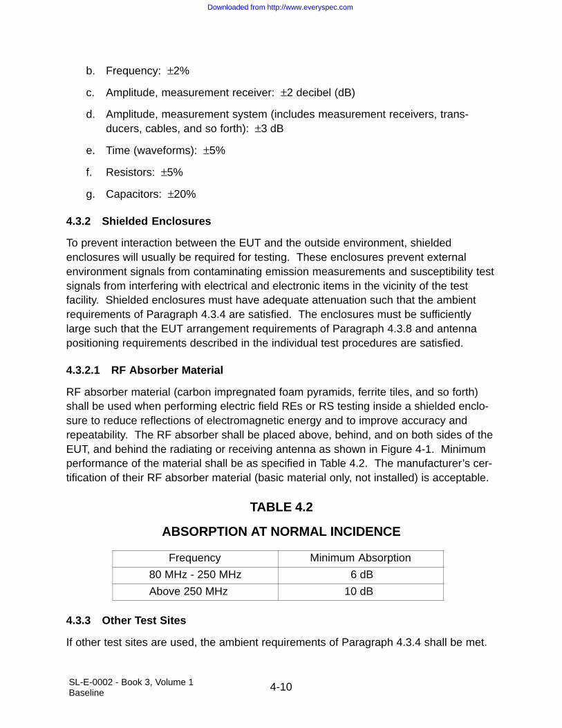
4.3.2.1 RF Absorber Material
RF absorber material (carbon impregnated foam pyramids, ferrite tiles, and so forth)shall be used when performing electric field REs or RS testing inside a shielded enclo-sure to reduce reflections of electromagnetic energy and to improve accuracy andrepeatability. The RF absorber shall be placed above, behind, and on both sides of theEUT, and behind the radiating or receiving antenna as shown in Figure 4-1. Minimumperformance of the material shall be as specified in Table 4.2. The manufacturer’s cer-tification of their RF absorber material (basic material only, not installed) is acceptable.
TABLE 4.2
ABSORPTION AT NORMAL INCIDENCE
Frequency Minimum Absorption
80 MHz - 250 MHz 6 dB
Above 250 MHz 10 dB
4.3.3 Other Test Sites
If other test sites are used, the ambient requirements of Paragraph 4.3.4 shall be met.
Downloaded from http://www.everyspec.com

4-11SL-E-0002 - Book 3, Volume 1Baseline
4.3.4 Ambient Electromagnetic Level
During testing, the ambient electromagnetic level measured with the EUT de-energizedand all auxiliary equipment turned on shall be at least 6 dB below the allowable speci-fied limits when the tests are performed in a shielded enclosure. Ambient conductedlevels on power leads shall be measured with the leads disconnected from the EUT andconnected to a resistive load which draws the same rated current as the EUT. Whentests are performed in a shielded enclosure and the EUT is in compliance with requiredlimits, the ambient profile need not be recorded in the EMITR. However, if the ambientprofile is recorded it should be include in the EMITR. When measurements are madeoutside a shielded enclosure, the tests shall be performed during times and conditionswhen the ambient is at its lowest level. The ambient shall be recorded in the EMITRand shall not compromise the test results.
4.3.5 Ground Plane
The EUT shall be installed on a ground plane that simulates the actual installation. Ifthe actual installation is unknown or multiple installations are expected, then a metallicground plane shall be used. Unless otherwise specified below, ground planes shall be2.25 square meters or larger in area with the smaller side no less than 76 centimeters(cm). When a ground plane is not present in the EUT installation, the EUT shall beplaced on a non-conductive table.
4.3.5.1 Metallic Ground Plane
When the EUT is installed on a metallic ground plane, the ground plane shall have asurface resistance no greater than 0.1 milliohms per square. The DC resistancebetween metallic ground planes and the shielded enclosure shall be 2.5 milliohms orless. The metallic ground planes shown in Figure 4-2 through Figure 4-5 shall be elec-trically bonded to the floor or wall of the basic shielded room structure at least onceevery 1 meter. The metallic bond straps shall be solid and maintain a 5-to-1 ratio orless in length to width. Metallic ground planes used outside a shielded enclosure shallextend at least 1.5 meters beyond the test setup boundary in each direction.
4.3.5.2 Composite Ground Plane
When the EUT is installed on a conductive composite ground plane, the surface resis-tivity of the typical installation shall be used. Composite ground planes shall beelectrically bonded to the enclosure with means suitable to the material.
4.3.6 Power Source Impedance
The impedance of power sources providing input power to the EUT shall be controlledby LISNs for all measurement procedures of this document unless otherwise stated in a
Downloaded from http://www.everyspec.com

4-12SL-E-0002 - Book 3, Volume 1Baseline
particular test procedure. LISNs shall not be used on output power leads. The LISNsshall be located at the power source end of the exposed length of power leads speci-fied in Paragraph 4.3.8.6.2. Two different LISNs are required in this specification. TheLISN circuit for all tests except TT101 shall be in accordance with the schematic shownin Figure 4-6. The LISN impedance characteristics of the Figure 4-6 LISN shall be inaccordance with Figure 4-7. The LISN impedance shall be measured at least annuallyunder the following conditions:
a. The impedance shall be measured between the power output lead on the loadside of the LISN and the metal enclosure of the LISN.
b. The signal output port of the LISN shall be terminated in 50 ohms.
c. The power input terminal on the power source side of the LISN shall be unterminated.
Impedance characteristics and circuitry for the TT101 LISN is described in that test sec-tion. Impedance is verified as follows:
a. The impedance shall be measured between the positive and negative poweroutput leads on the load side of the LISN.
b. The positive and negative power input terminals on the power source side ofthe LISN shall be shorted together.
The impedance measurement results shall be provided in the EMITR.
4.3.7 General Test Precautions
4.3.7.1 Accessory Equipment
Accessory equipment used in conjunction with measurement receivers shall notdegrade measurement integrity.
4.3.7.2 Excess Personnel and Equipment
The test area shall be kept free of unnecessary personnel, equipment, cable racks, anddesks. Only the equipment essential to the test being performed shall be in the testarea or enclosure. Only personnel actively involved in the test shall be permitted in theenclosure.
4.3.7.3 Overload Precautions
Measurement receivers and transducers are subject to overload, especially receiverswithout preselectors and active transducers. Periodic checks shall be performed to
Downloaded from http://www.everyspec.com

4-13SL-E-0002 - Book 3, Volume 1Baseline
assure that an overload condition does not exist. Instrumentation changes shall beimplemented to correct any overload condition.
4.3.7.4 RF Hazards
Some tests in this specification will result in electromagnetic fields which are potentiallydangerous to personnel. The permissible exposure levels in IEEE C95.1-1991, IEEEStandard for Safety Levels with Respect to Human Exposure to Radio Frequency Elec-tromagnetic Fields, 3 kHz to 300 Gigahertz (GHz), shall not be exceeded in areaswhere personnel are present. Safety procedures and devices shall be used to preventaccidental exposure of personnel to RF hazards.
4.3.7.5 Shock Hazards
Some of the tests require potentially hazardous voltages to be present. Extreme cau-tion must be taken by all personnel to assure that all safety precautions are observed.
4.3.7.6 Federal Communications Commission (FCC) Restrictions
All planned open site radiation tests (i.e., outside of shielded enclosures) shall be pre-coordinated and approved by the National Telecommunications and InformationAdministration (NTIA) and/or the FCC, whichever is applicable, regardless of the levelof signals used. Authorization shall be secured prior to conducting the test readinessreview. Test sponsor(s) and test facility personnel shall contact the respective NASAField Center Spectrum Manager at the earliest possible stage of the test planning withall pertinent RF systems parameters and configuration data to facilitate the authoriza-tion process.
4.3.8 EUT Test Configurations
The EUT shall be configured as shown in the general test setups of Figure 4-1 throughFigure 4-5, as applicable. These setups shall be maintained during all testing unlessother direction is given for a particular test procedure.
4.3.8.1 EUT Design Status
EUT hardware, software, and firmware shall be representative of production. Softwaremay be supplemented with additional code that provides diagnostic capability to assessperformance.
4.3.8.2 Bonding of EUT
Only the provisions included in the design of the EUT shall be used to bond units suchas equipment case and mounting bases together, or to the ground plane. When
Downloaded from http://www.everyspec.com

4-14SL-E-0002 - Book 3, Volume 1Baseline
bonding straps are required, they shall be identical to those specified in the installationdrawings.
4.3.8.3 Shock and Vibration Isolators
EUTs shall be secured to mounting bases having shock or vibration isolators if suchmounting bases are used in the installation. The bonding straps furnished with themounting base shall be connected to the ground plane. When mounting bases do nothave bonding straps, bonding straps shall not be used in the test setup.
4.3.8.4 Safety Grounds
When external terminals, connector pins, or equipment grounding conductors are avail-able for safety ground connections and are used in the actual installation, they shall beconnected to the ground plane. Arrangement and length shall be in accordance withParagraph 4.3.8.6.1.
4.3.8.5 Orientation of EUTs
EUTs shall be oriented such that surfaces which produce maximum REs and respondmost readily to radiated signals face the measurement antennas. Bench mountedEUTs shall be located 10 ±2 cm from the front edge of the ground plane subject toallowances for providing adequate room for cable arrangement as specified below.
4.3.8.6 Construction and Arrangement of EUT Cables
Electrical cable assemblies shall simulate actual installation and usage. Shieldedcables or shielded leads (including power leads and wire grounds) within cables shallbe used only if they have been specified in installation requirements. Cables shall bechecked against installation requirements to verify proper construction techniques suchas use of twisted pairs, shielding, and shield terminations. Details on the cableconstruction, such as wire types, lengths, pigtail lengths, shield termination, lengths ofground wires, and ground locations, used for testing shall be included in the EMITP.
4.3.8.6.1 Interconnecting Leads and Cables
Individual leads shall be grouped into cables in the same manner as in the actual instal-lation. Interconnecting cable lengths in the test setup shall represent the actual lengthsin the SSV, unless the actual vehicle lengths are less than that allowed to meet the fol-lowing conditions. Cable lengths, when not specified for the installation, shall besufficiently long to achieve a two meter run along the ground plane edge. At least thefirst two meters of each interconnecting cable associated with each enclosure of the
Downloaded from http://www.everyspec.com

4-15SL-E-0002 - Book 3, Volume 1Baseline
EUT shall be run parallel to the front boundary of the setup. Remaining cable lengthsshall be routed to the back of the setup and shall be placed in a zig-zagged arrange-ment. When the setup includes more than one cable, individual cables shall beseparated by two centimeters measured from their outer circumference. For bench topsetups using ground planes, cables shall be placed within the first ten centimeters fromthe front edge of the ground plane. All cables shall be supported five centimetersabove the ground plane.
4.3.8.6.2 Input Power Leads
Two meters of input power leads, including neutrals and returns, shall be routed parallelto the front edge of the setup in the same manner as the interconnecting leads. Eachinput power lead, including neutrals and returns, shall be connected to a LISN (refer-ence Paragraph 4.3.6). Power leads that are bundled as part of an interconnectingcable in the actual installation shall be configured in the same fashion for the 2 meterexposed length and then shall be separated from the bundle and routed to the LISNs.After the 2 meter exposed length, the power leads shall be terminated at the LISNs inas short a distance as possible. The total length of power lead from the EUT electricalconnector to the LISNs shall not exceed 2.5 meters. All power leads shall be supported5 cm above the ground plane. If the power leads are twisted in the actual installation,they shall be twisted up to the LISNs.
4.3.8.7 Electrical and Mechanical Interfaces
All electrical input and output interfaces shall be terminated with either the actual equip-ment from the platform installation or loads external to the EUT which simulate theelectrical properties (impedance, grounding, balance, and so forth) present in the actualinstallation. Signal inputs shall be applied to all applicable electrical interfaces to exer-cise EUT circuitry. EUTs with mechanical outputs shall be suitably loaded. Whenvariable electrical or mechanical loading is present in the actual installation, testingshall be performed under expected worst case conditions. When active electricalloading (such as a test set) is used, precautions shall be taken to insure the active loadmeets the ambient requirements of Paragraph 4.3.4 when connected to the setup, andthat the active load does not respond to susceptibility signals. Antenna ports on theEUT shall be terminated with shielded, matched loads.
4.3.9 Operation of EUT
During emission measurements, the EUT shall be placed in an operating mode whichproduces maximum emissions. During susceptibility testing, the EUT shall be placed inits most susceptible operating mode. For EUTs with several available modes, includingsoftware controlled operational modes, a sufficient number of modes shall be tested for
Downloaded from http://www.everyspec.com

4-16SL-E-0002 - Book 3, Volume 1Baseline
emissions and susceptibility such that all circuitry is evaluated. If production softwareor firmware is not available, justification that the software or firmware used for the testis able to activate or exercise the EUT in a manner equivalent to production software orfirmware shall be shown. The rationale for modes selected shall be included in theEMITP. A functional test of the EUT shall be performed as a minimum before and afterthe entire test series.
4.3.9.1 Operating Frequencies for Tunable RF Equipment
Measurements shall be performed with the EUT tuned to not less than three frequen-cies within each tuning band, tuning unit, or range of fixed channels, consisting of onemid-band frequency and a frequency within ±5 percent from each end of each band orrange of channels.
4.3.9.2 Operating Frequencies for Spread Spectrum Equipment
Operating frequency requirements for two major types of spread spectrum equipmentshall be as follows:
a. Frequency hopping. Measurements shall be performed with the EUT utilizing ahop set which contains a minimum of 30% of the total possible frequencies.This hop set shall be divided equally into three segments at the low, mid, andhigh end of the EUT’s operational frequency range.
b. Direct sequence. Measurements shall be performed with the EUT processingdata at the highest possible data transfer rate.
4.3.9.3 Susceptibility Monitoring
The EUT shall be monitored during susceptibility testing for indications of degradationor malfunction. This monitoring is normally accomplished through the use of built-in-test, visual displays, aural outputs, and other measurements of signal outputs andinterfaces. Monitoring of EUT performance through installation of special circuitry in theEUT is permissible; however, these modifications shall not influence test results.
4.3.10 Use of Measurement Equipment
Measurement equipment shall be as specified in the individual test procedures ofthis specification. Any frequency selective measurement receiver may be used forperforming the testing described in this specification provided that the receiver charac-teristics (that is, sensitivity, selection of BWs, detector functions, dynamic range, andfrequency of operation) meet the constraints specified in this specification and are suffi-cient to demonstrate compliance with the applicable limits. Typical instrumentation
Downloaded from http://www.everyspec.com

4-17SL-E-0002 - Book 3, Volume 1Baseline
characteristics may be found in ANSI C63.2, Standard for Instrumentation Electromag-netic Noise and Field Strength, 10 kHz to 40 GHz, Specifications.
4.3.10.1 Detector
A peak detector shall be used for all frequency domain emission and susceptibility mea-surements. This device detects the peak value of the modulation envelope in thereceiver bandpass. Measurement receivers are calibrated in terms of an equivalentRoot Mean Square (RMS) value of a sine wave that produces the same peak value.When other measurement devices such as oscilloscopes, non-selective voltmeters, orbroadband field strength sensors are used for susceptibility testing, correction factorsshall be applied for test signals to adjust the reading to equivalent RMS values underthe peak of the modulation envelope.
4.3.10.2 Computer-controlled Receivers
A description of the operations being directed by software for computer-controlledreceivers shall be included in the EMITP. Verification techniques used to demonstrateproper performance of the software shall also be included.
4.3.10.3 Emission Testing
4.3.10.3.1 Bandwidths
The measurement receiver BWs listed in Table 4.3 shall be used for emission testing.These BWs are specified at the 6 dB down points for the overall selectivity curve of thereceivers. Video filtering shall not be used to BW limit the receiver response. If a con-trolled video BW is available on the measurement receiver, it shall be set to its greatestvalue. Larger receiver BWs may be used; however, they may result in higher mea-sured emission levels.
NOTE: No BW correction factors shall be applied to test data due to the use of largerBWs.
Downloaded from http://www.everyspec.com

4-18SL-E-0002 - Book 3, Volume 1Baseline
TABLE 4.3
BW AND MEASUREMENT TIME
Frequency Range 6 dB BW Dwell TimeMinimum Measurement Time
Analog Measurement Receiver
30 Hz - 1 kHz 10 Hz 0.15 sec 0.015 sec/Hz
1 kHz - 10 kHz 100 Hz 0.015 sec 0.15 sec/kHz
10 kHz - 150 kHz 1 kHz 0.015 sec 0.015 sec/kHz
150 kHz - 30 MHz 10 kHz 0.015 sec 1.5 sec/MHz
30 MHz - 1 GHz 100 kHz 0.015 sec 0.15 sec/MHz
Above 1 GHz 1 MHz 0.015 sec 15 sec/GHz
4.3.10.3.2 Emission Identification
All emissions, regardless of characteristics, shall be measured with the measurementreceiver BWs specified in Table 4.3 and compared against the applicable limits. Identifi-cation of emissions with regard to narrowband or broadband categorization is notapplicable.
4.3.10.3.3 Frequency Scanning
For emission measurements, the entire frequency range for each applicable test shallbe scanned. Minimum measurement time for analog measurement receivers duringemission testing shall be as specified in Table 4.3. Synthesized measurementreceivers shall step in one-half BW increments or less, and the measurement dwell timeshall be as specified in Table 4.3. For equipment that operates such that potentialemissions are produced at only infrequent intervals, times for frequency scanning shallbe increased as necessary to capture any emissions. For equipment which operatesfor very short durations, or which has a limited life, scan times may be reduced. Justifi-cation for such reduction will be presented in the EMITP, and approved by thedesignated approving authority prior to test.
4.3.10.3.4 Emission Data Presentation
Amplitude versus frequency profiles of emission data shall be automatically generatedand displayed at the time of test and shall be continuous. The displayed informationshall account for all applicable correction factors (transducers, attenuators, cable loss,and the like) and shall include the applicable limit. Manually gathered data is notacceptable except for verification of the validity of the output. Plots of the displayeddata shall provide a minimum frequency resolution of 1% or twice the measurement
Downloaded from http://www.everyspec.com

4-19SL-E-0002 - Book 3, Volume 1Baseline
receiver BW, whichever is less stringent, and minimum amplitude resolution of 1 dB.The above resolution requirements shall be maintained in the reported results of theEMITR.
4.3.10.4 Susceptibility Testing
4.3.10.4.1 Frequency Scanning
For susceptibility measurements, the entire frequency range for each applicable testshall be scanned. For swept frequency susceptibility testing, frequency scan rates andfrequency step sizes of signal sources shall not exceed the values listed in Table 4.4.The rates and step sizes are specified in terms of a multiplier of the tuned frequency (fo)of the signal source. Analog scans refer to signal sources, which are continuouslytuned. Stepped scans refer to signal sources, which are sequentially tuned to discretefrequencies. Stepped scans shall dwell at each tuned frequency for the greater of threeseconds or the EUT response time. Scan rates and step sizes shall be decreasedwhen necessary to permit observation of a response.
TABLE 4.4
SUSCEPTIBILITY SCANNING
Frequency RangeAnalog Scans
Maximum Scan RatesStepped Scans
Maximum Step Size
30 Hz - 1 MHz 0.0333fo/sec 0.05 fo
1 MHz - 30 MHz 0.00667 fo/sec 0.01 fo
30 MHz - 1 GHz 0.00333 fo/sec 0.005 fo
1 GHz - 8 GHz 0.000667 fo/sec 0.001 fo
8 GHz - 40 GHz 0.000333 fo/sec 0.0005 fo
4.3.10.4.2 Modulation of Susceptibility Signals
Susceptibility modulation requirements are located with the susceptibility requirement.If pulse modulation is not available below 1 GHz, amplitude modulation at 99% depthshall be substituted. With this option, care shall be exercised that the peak of the mod-ulation envelope corresponds to the limit level stress.
4.3.10.4.3 Thresholds of Susceptibility
When susceptibility indications are noted in EUT operation, a threshold level shall bedetermined where the susceptible condition is no longer present. Thresholds of sus-ceptibility shall be determined as follows and described in the EMITR:
Downloaded from http://www.everyspec.com

4-20SL-E-0002 - Book 3, Volume 1Baseline
a. When a susceptibility condition is detected, reduce the interference signal untilthe EUT recovers.
b. Reduce the interference signal by an additional 6 dB.
c. Gradually increase the interference signal until the susceptibility condition reoccurs. The resulting level is the threshold of susceptibility.
d. Record this level, frequency range of occurrence, frequency and level ofgreatest susceptibility, and other test parameters, as applicable.
4.3.11 Calibration of Measuring Equipment
Test equipment and accessories required for measurement in accordance with thisspecification shall be calibrated in accordance with ANSI/NCSL Z540-1, GeneralRequirements for Calibration Laboratories and Measuring and Test Equipment, or ISO10012-1, Quality Assurance Requirements for Measuring Equipment, or under anapproved calibration program traceable to the National Institute for Standards andTechnology. In particular, measurement antennas, current probes, field sensors, andother devices used in the measurement loop shall be calibrated at least every twoyears unless otherwise specified by the procuring activity, or when damage is apparent.
4.3.11.1 Measurement System Test
At the start of each emission test, the complete test system (including measurementreceivers, cables, attenuators, couplers, and so forth) shall be verified by injecting aknown signal, as stated in the individual test procedure, while monitoring system outputfor the proper indication. When the emission test involves an uninterrupted set ofrepeated measurements (such as evaluating different operating modes of the EUT)using the same measurement equipment, the measurement system test needs to beaccomplished only one time.
4.3.11.2 Antenna Factors
Factors for test antennas shall be determined in accordance with SAE ARP-958, Elec-tromagnetic Interference Measurement Antennas, Standard Calibration Requirementsand Methods.
Downloaded from http://www.everyspec.com

4-21SL-E-0002 - Book 3, Volume 1Baseline
FIGURE 4-1
RF ABSORBER LOADING DIAGRAM
TestAntenna
TE
ST
SE
TU
PB
OU
ND
AR
Y
≥30
cm
30 cm
RF absorber placed above,behind and on both sides oftest setup boundary, fromceiling to ground plane
RF absorber placedbehind test antenna,from ceiling to floor
30 cm
30 c
m
50 c
m
≥ ≥
≥
≥
Downloaded from http://www.everyspec.com

4-22S
L-E-0002 - B
ook 3, Volum
e 1B
aseline
FIGURE 4-2
GENERAL TEST SETUP
2 m80-90 cm
EUT
Bond StrapPowerSource Interconnecting Cable
2 cm LISNs
Ground Plane10 cm
5 cm
Non-Conductive Standoff
AccessPanel
Downloaded from http://www.everyspec.com

4-23S
L-E-0002 - B
ook 3, Volum
e 1B
aseline
FIGURE 4-3
TEST SETUP FOR NON-CONDUCTIVE SURFACE MOUNTED EUT
2 m
PowerSource Interconnecting Cable
80-90 cm
EUT
Bond Strap
10 cm
2 cm LISNs
GroundPlane
Non-Conductive Table
AccessPanel
Downloaded from http://www.everyspec.com

4-24S
L-E-0002 - B
ook 3, Volum
e 1B
aseline
FIGURE 4-4
TEST SETUP FOR FREE STANDING EUT IN SHIELDED ENCLOSURE
EUTEnclosureAccess Panel
5 cm
Ground Plane -Shielded Room
Floor2 m
LISNs
Power Input
Interconnecting Cable
Bond Strap
Non-Conductive Standoff
Downloaded from http://www.everyspec.com

4-25SL-E-0002 - Book 3, Volume 1Baseline
FIGURE 4-5
TEST SETUP FOR FREE STANDING EUT
Non-ConductiveStandoff
2 m
LISNs
Power In
1.5 MetersMinimum
1.5 MetersMinimum
1.5 MetersMinimum
1.5 MetersMinimum
5 cm
Ground Plane
Downloaded from http://www.everyspec.com

4-26SL-E-0002 - Book 3, Volume 1Baseline
FIGURE 4-6
LISN SCHEMATIC
To EUT
To 50 TerminationOr 50 Input OfMeasurementReceiver
ΩΩ
ToPower
Source
Signal OutputPort
5Ω 1kΩ
50 µH
8 µF 0.25µF
Downloaded from http://www.everyspec.com

4-27SL-E-0002 - Book 3, Volume 1Baseline
FIGURE 4-7
LISN IMPEDANCE
Frequency (Hz)
Impedance (O
hms)
Tolerance ±20%100
10
110k 100k 1M 10M 100M
Downloaded from http://www.everyspec.com

4-28SL-E-0002 - Book 3, Volume 1Baseline
THIS PAGE INTENTIONALLY LEFT BLANK
Downloaded from http://www.everyspec.com

5-1SL-E-0002 - Book 3, Volume 1Baseline
5.0 DETAILED REQUIREMENTS
5.1 GENERAL
This section specifies detailed emissions and susceptibility requirements and the asso-ciated test procedures. Table 5.1 is a list of the specific requirements established bythis standard identified by requirement number and title. General test procedures areincluded in this section. Specific test procedures are implemented by the approvedEMITP. All results of tests performed to demonstrate compliance with the requirementsare to be documented in the EMITR and forwarded to the designated authority for eval-uation prior to acceptance of the equipment or subsystem. Design procedures andtechniques for the control of EMI shall be described in the EMICP. Approval of designprocedures and techniques described in the EMICP does not relieve the supplier of theresponsibility of meeting the contractual emission, susceptibility, and design requirements.
5.1.1 Units of Frequency Domain Measurements
All frequency domain limits are expressed in terms of equivalent RMS value of a sinewave as would be indicated by the output of a measurement receiver using peak enve-lope detection (reference Paragraph 4.3.10.1).
Downloaded from http://www.everyspec.com
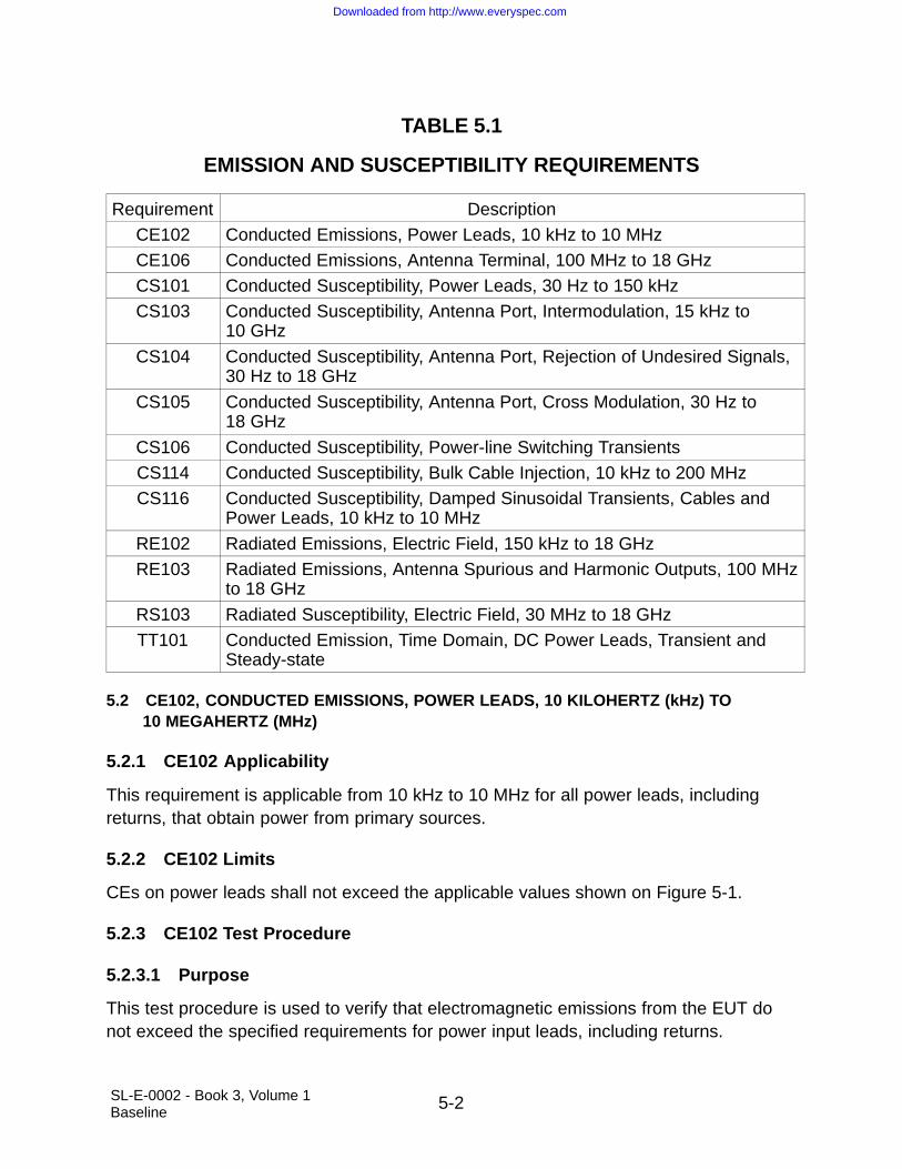
5-2SL-E-0002 - Book 3, Volume 1Baseline
TABLE 5.1
EMISSION AND SUSCEPTIBILITY REQUIREMENTS
Requirement DescriptionCE102 Conducted Emissions, Power Leads, 10 kHz to 10 MHzCE106 Conducted Emissions, Antenna Terminal, 100 MHz to 18 GHzCS101 Conducted Susceptibility, Power Leads, 30 Hz to 150 kHzCS103 Conducted Susceptibility, Antenna Port, Intermodulation, 15 kHz to
10 GHz
CS104 Conducted Susceptibility, Antenna Port, Rejection of Undesired Signals,30 Hz to 18 GHz
CS105 Conducted Susceptibility, Antenna Port, Cross Modulation, 30 Hz to 18 GHz
CS106 Conducted Susceptibility, Power-line Switching TransientsCS114 Conducted Susceptibility, Bulk Cable Injection, 10 kHz to 200 MHzCS116 Conducted Susceptibility, Damped Sinusoidal Transients, Cables and
Power Leads, 10 kHz to 10 MHz
RE102 Radiated Emissions, Electric Field, 150 kHz to 18 GHzRE103 Radiated Emissions, Antenna Spurious and Harmonic Outputs, 100 MHz
to 18 GHz
RS103 Radiated Susceptibility, Electric Field, 30 MHz to 18 GHzTT101 Conducted Emission, Time Domain, DC Power Leads, Transient and
Steady-state
5.2 CE102, CONDUCTED EMISSIONS, POWER LEADS, 10 KILOHERTZ (kHz) TO 10 MEGAHERTZ (MHz)
5.2.1 CE102 Applicability
This requirement is applicable from 10 kHz to 10 MHz for all power leads, includingreturns, that obtain power from primary sources.
5.2.2 CE102 Limits
CEs on power leads shall not exceed the applicable values shown on Figure 5-1.
5.2.3 CE102 Test Procedure
5.2.3.1 Purpose
This test procedure is used to verify that electromagnetic emissions from the EUT donot exceed the specified requirements for power input leads, including returns.
Downloaded from http://www.everyspec.com
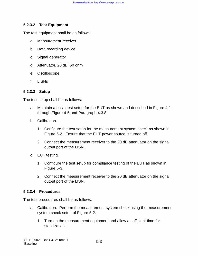
5-3SL-E-0002 - Book 3, Volume 1Baseline
5.2.3.2 Test Equipment
The test equipment shall be as follows:
a. Measurement receiver
b. Data recording device
c. Signal generator
d. Attenuator, 20 dB, 50 ohm
e. Oscilloscope
f. LISNs
5.2.3.3 Setup
The test setup shall be as follows:
a. Maintain a basic test setup for the EUT as shown and described in Figure 4-1through Figure 4-5 and Paragraph 4.3.8.
b. Calibration.
1. Configure the test setup for the measurement system check as shown inFigure 5-2. Ensure that the EUT power source is turned off.
2. Connect the measurement receiver to the 20 dB attenuator on the signaloutput port of the LISN.
c. EUT testing.
1. Configure the test setup for compliance testing of the EUT as shown inFigure 5-3.
2. Connect the measurement receiver to the 20 dB attenuator on the signaloutput port of the LISN.
5.2.3.4 Procedures
The test procedures shall be as follows:
a. Calibration. Perform the measurement system check using the measurementsystem check setup of Figure 5-2.
1. Turn on the measurement equipment and allow a sufficient time for stabilization.
Downloaded from http://www.everyspec.com

5-4SL-E-0002 - Book 3, Volume 1Baseline
2. Apply a signal level that is at least 6 dB below the limit at 10 kHz, 100 kHz,2 MHz and 10 MHz to the power output terminal of the LISN. At 10 kHzand 100 kHz, use an oscilloscope to calibrate the signal level and verifythat it is sinusoidal. At 2 MHz and 10 MHz, use a calibrated output leveldirectly from a 50 ohm signal generator.
3. Scan the measurement receiver for each frequency in the same manner asa normal data scan. Verify that the measurement receiver indicates a levelwithin ±3 dB of the injected level. Correction factors shall be applied for the20 dB attenuator and the voltage drop due to the LISN 0.25 microfaradcoupling capacitor.
4. If readings are obtained which deviate by more than ±3 dB, locate thesource of the error and correct the deficiency prior to proceeding with thetesting.
5. Repeat Items 2 through 4 (above) for each LISN.
b. EUT testing. Perform emission data scans using the measurement setup ofFigure 5-3.
1. Turn on the EUT and allow a sufficient time for stabilization.
2. Select an appropriate lead for testing.
3. Scan the measurement receiver over the applicable frequency range, usingthe BWs and minimum measurement times in Table 4.3.
4. Repeat Items 2 and 3 (above) for each power lead.
5.2.3.5 Data Presentation
Data presentation shall be as follows:
a. Continuously and automatically plot amplitude versus frequency profiles onX–Y axis outputs. Manually gathered data is not acceptable except for plotverification.
b. Display the applicable limit on each plot.
c. Provide a minimum frequency resolution of 1% or twice the measurementreceiver BW, whichever is less stringent, and a minimum amplitude resolutionof 1 dB for each plot.
d. Provide plots for both the measurement system check and measurementportions of the procedure.
Downloaded from http://www.everyspec.com
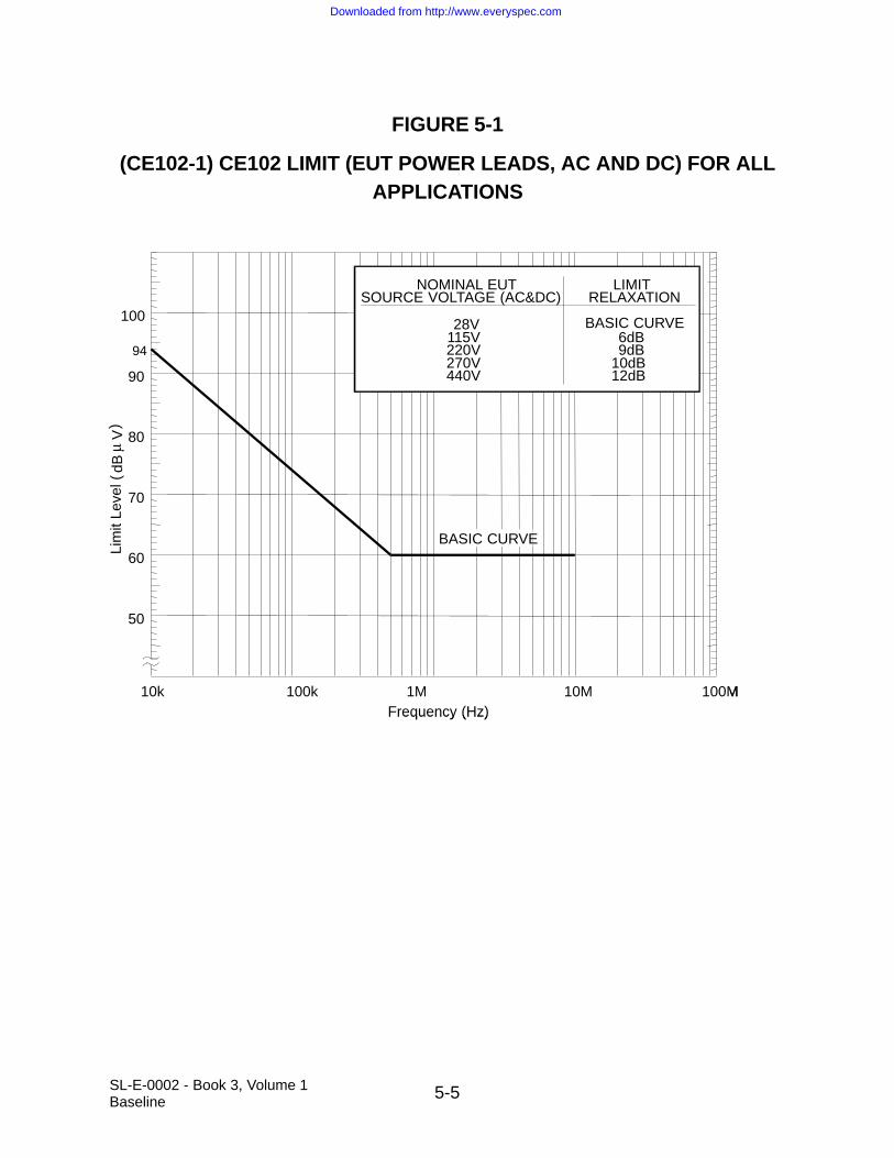
5-5SL-E-0002 - Book 3, Volume 1Baseline
FIGURE 5-1
(CE102-1) CE102 LIMIT (EUT POWER LEADS, AC AND DC) FOR ALLAPPLICATIONS
Limit Level (
dBµ V
)
100
90
80
70
60
50
94
10k 100k 1M 10M 100MFrequency (Hz)
BASIC CURVE
NOMINAL EUTSOURCE VOLTAGE (AC&DC)
LIMITRELAXATION
BASIC CURVE6dB9dB
10dB12dB
28V115V220V270V440V
Lim
it Le
vel (
dBV
)
100
90
80
70
60
50
94
10k 100k 1M 10M 100MFrequency (Hz)
BASIC CURVE
NOMINAL EUTSOURCE VOLTAGE (AC&DC)
LIMITRELAXATION
BASIC CURVE6dB9dB
10dB12dB
28V115V220V270V440V
µ
Downloaded from http://www.everyspec.com

5-6SL-E-0002 - Book 3, Volume 1Baseline
FIGURE 5-2
(CE102-2) MEASUREMENT SYSTEM CHECK SETUP
Downloaded from http://www.everyspec.com
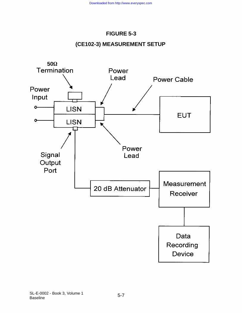
5-7SL-E-0002 - Book 3, Volume 1Baseline
FIGURE 5-3
(CE102-3) MEASUREMENT SETUP
50
Downloaded from http://www.everyspec.com

5-8SL-E-0002 - Book 3, Volume 1Baseline
5.3 CE106, CONDUCTED EMISSIONS, ANTENNA TERMINAL, 100 MHz TO 18 GHz
5.3.1 CE106 Applicability
This requirement is applicable to the antenna terminals of transmitters, receivers, andamplifiers. The requirement is not applicable to equipment designed with antennaspermanently mounted to the EUT. The transmit mode portion of this requirement is notapplicable within the EUT necessary BW and within ±5 percent of the fundamental fre-quency. The start frequency of the test is 100 MHz for all EUT operating frequencyranges. The end frequency of the test is 18 GHz or twenty times the highest generatedor received frequency within the EUT, whichever is less. For equipment using wave-guide, the requirement does not apply below eight-tenths of the waveguide’s cutofffrequency. RE103 may be used as an alternative for CE106 for testing transmitterswith their operational antennas. RE102 is applicable for emissions from antennas inthe receive and standby modes for equipment designed with antennas permanentlymounted to the EUT.
5.3.2 CE106 Limits
CEs at the EUT antenna terminal shall not exceed the values given below.
a. Receivers: 34 decibel microvolts (dBµV)
b. Transmitters and amplifiers (standby mode): 34 dBµV
c. Transmitters and amplifiers (transmit mode): Harmonics, except the secondand third, and all other spurious emissions shall be at least 80 dB down fromthe level at the fundamental. The second and third harmonics shall be sup-pressed 50 + 10 log p (where p = peak power output in watts, at thefundamental) or 80 dB, whichever requires less suppression.
5.3.3 CE106 Test Procedure
5.3.3.1 Purpose
This test procedure is used to verify that CEs appearing at the antenna terminal of theEUT do not exceed specified requirements.
5.3.3.2 Test Equipment
The test equipment shall be as follows:
a. Measurement receiver.
b. Attenuators, 50 ohm.
Downloaded from http://www.everyspec.com

5-9SL-E-0002 - Book 3, Volume 1Baseline
c. Rejection networks.
d. Directional couplers.
e. Dummy loads, 50 ohm.
f. Signal generators. For amplifier testing, a signal generator is required to drivethe amplifier that provides the modulation used in the intended application andthat has spurious and harmonic outputs that are down at least 6 dB greaterthan the applicable limit.
g. Data recording device.
5.3.3.3 Setup
It is not necessary to maintain the basic test setup for the EUT as shown and describedin Figure 4-2 through Figure 4-5 and Paragraph 4.3.8. The test setup shall be asfollows:
a. Calibration. Configure the test setup for the signal generator path shown inFigure 5-1 through Figure 5-3, as applicable. The choice of Figure 5-1 orFigure 5-2 is dependent upon the capability of the measuring equipment tohandle the transmitter power.
b. EUT Testing. Configure the test setup for the EUT path shown in Figure 5-1through Figure 5-3, as applicable. The choice of Figure 5-1 or Figure 5-2 isdependent upon the capability of the measuring equipment to handle the trans-mitter power.
5.3.3.4 Procedures
5.3.3.4.1 Transmit Mode for Transmitters and Amplifiers
The test procedure shall be as follows:
a. Turn on the measurement equipment and allow a sufficient time for stabilization.
b. Calibration.
1. Apply a known calibrated signal level from the signal generator through thesystem check path at a mid-band fundamental frequency (fo).
2. Scan the measurement receiver in the same manner as a normal datascan. Verify the measurement receiver detects a level within ±3 dB of theexpected signal.
Downloaded from http://www.everyspec.com

5-10SL-E-0002 - Book 3, Volume 1Baseline
3. If readings are obtained which deviate by more than ±3 dB, locate thesource of the error and correct the deficiency prior to proceeding with thetest.
4. Repeat Items 1 through 3 (above) at the end points of the frequency rangeof test.
c. EUT Testing.
1. Turn on the EUT and allow sufficient time for stabilization.
2. For transmitters, tune the EUT to the desired test frequency and apply theappropriate modulation for the EUT as indicated in the equipment specifica-tion. For amplifiers, apply an input signal to the EUT that has theappropriate frequency, power level, and modulation as indicated in theequipment specification. For transmitters and amplifiers for which theseparameters vary, test parameters shall be chosen such that the worst caseemissions spectrum will result.
3. Use the measurement path to complete the rest of this procedure.
4. Tune the test equipment to the operating frequency (fo) of the EUT andadjust for maximum indication.
5. Record the power level of the fundamental frequency (fo) and the measure-ment receiver BW.
6. Insert the fundamental frequency rejection network, when applicable.
7. Scan the frequency range of interest and record the level of all harmonicsand spurious emissions. Add all correction factors for cable loss, attenua-tors and rejection networks. Maintain the same measurement receiverBW used to measure the power level of the fundamental frequency (fo) inStep c, Item 5 (above).
8. Verify spurious outputs are from the EUT and not spurious responses of themeasurement system.
9. Repeat Items 2 through 8 (above) for other frequencies as required byParagraph 4.3.9.1 and Paragraph 4.3.9.2.
10. Determine measurement path losses at each spurious frequency as follows:
(a) Replace the EUT with a signal generator.
Downloaded from http://www.everyspec.com
5-11SL-E-0002 - Book 3, Volume 1Baseline
(b) Retain all couplers and rejection networks in the measurement path.
(c) Determine the losses through the measurement path. The value ofattenuators may be reduced to facilitate the end-to-end check with alow level signal generator.
5.3.3.4.2 Recievers and Stand-by Mode for Transmitters and Amplifiers
The test procedure shall be as follows:
a. Turn on the measurement equipment and allow a sufficient time for stabilization.
b. Calibration.
1. Apply a calibrated signal level, which is 6 dB below the applicable limit,from the signal generator through the system check path at a midpoint testfrequency.
2. Scan the measurement receiver in the same manner as a normal datascan. Verify the measurement receiver detects a level within ±3 dB of theinjected signal.
3. If readings are obtained which deviate by more than ±3 dB, locate thesource of the error and correct the deficiency prior to proceeding with thetest.
4. Repeat Items 1 through 3 (above) at the end points of the frequency rangeof test.
c. EUT Testing.
1. Turn on the EUT and allow sufficient time for stabilization.
2. Tune the EUT to the desired test frequency and use the measurement pathto complete the rest of this procedure.
3. Scan the measurement receiver over the applicable frequency range, usingthe BWs and minimum measurement times of Table 4.3.
4. Repeat Items 2 and 3 (above) for other frequencies as required by Paragraph 4.3.9.1 and Paragraph 4.3.9.2.
5.3.3.5 Data Presentation
5.3.3.5.1 Transmit Mode for Transmitters and Amplifiers
The data presentation shall be as follows:
a. Continuously and automatically plot amplitude versus frequency profiles foreach tuned frequency. Manually gathered data is not acceptable except for plotverification.
Downloaded from http://www.everyspec.com

5-12SL-E-0002 - Book 3, Volume 1Baseline
b. Provide a minimum frequency resolution of 1% or twice the measurementreceiver BW, whichever is less stringent, and a minimum amplitude resolutionof 1 dB for each plot
c. Provide tabular data showing fo and frequencies of all harmonics and spuriousemissions measured, power level of the fundamental and all harmonics andspurious emissions, dB down level, and all correction factors including cableloss, attenuator pads, and insertion loss of rejection networks.
d. The relative dB down level is determined by subtracting the level in Paragraph5.3.3.4.1, Step c, Item 7, from that obtained in Paragraph 5.3.3.4.1, Step c,Item 5.
5.3.3.5.2 Receivers and Stand-by Mode for Transmitters and Amplifiers
The data presentation shall be as follows:
a. Continuously and automatically plot amplitude versus frequency profiles foreach tuned frequency. Manually gathered data is not acceptable except for plotverification.
b. Display the applicable limit on each plot.
c. Provide a minimum frequency resolution of 1% or twice the measurementreceiver BW, whichever is less stringent, and a minimum amplitude resolutionof 1 dB for each plot.
d. Provide plots for both the measurement and system check portions of the procedure.
Downloaded from http://www.everyspec.com

5-13SL-E-0002 - Book 3, Volume 1Baseline
FIGURE 5-4
(CE106-1) SETUP FOR LOW POWER TRANSMITTERS ANDAMPLIFIERS
SignalGenerator
TransmitterEUT
Path forSystem Check
Path forMeasurement
If Required
Attenuator
MeasurementReceiver
RejectionNetwork
AmplifierEUT
SignalGenerator
Downloaded from http://www.everyspec.com

5-14SL-E-0002 - Book 3, Volume 1Baseline
FIGURE 5-5
(CE106-2) SETUP FOR HIGH POWER TRANSMITTERS ANDAMPLIFIERS
SignalGenerator
TransmitterEUT
Path forSystem Check
Path forMeasurement
If Required
Attenuator
MeasurementReceiver
RejectionNetwork
CouplerDummy Load
orShieldedAntenna
SignalGenerator
AmplifierEUT
Downloaded from http://www.everyspec.com

5-15SL-E-0002 - Book 3, Volume 1Baseline
FIGURE 5-6
(CE106-3) SETUP FOR RECEIVERS AND STAND-BY MODE FORTRANSMITTERS AND AMPLIFIERS
SignalGenerator
EUT
Path forSystem Check
Path forMeasurement
Attenuator
MeasurementReceiver
DataRecording
Device
Downloaded from http://www.everyspec.com

5-16SL-E-0002 - Book 3, Volume 1Baseline
5.4 CS101, CONDUCTED SUSCEPTIBILITY, POWER LEADS, 30 HERTZ (Hz) TO 150 kHz
5.4.1 CS101 Applicability
This requirement is applicable to equipment and subsystem AC and DC input powerleads, not including returns. If the EUT is DC operated, this requirement is applicableover the frequency range of 30 Hz to 150 kHz. If the EUT is AC operated, this require-ment is applicable starting from the second harmonic of the EUT power frequency andextending to 150 kHz.
5.4.2 CS101 Limit
The EUT shall not exhibit any malfunction, degradation of performance, or deviationfrom specified indications, beyond the tolerances indicated in the individual equipmentor subsystem specification, when subjected to a test signal with voltage levels as speci-fied in Figure 5-7 for these voltage levels. The requirement is also met when the powersource is adjusted to dissipate the power level shown in Figure 5-8 in a 0.5 ohm loadand the EUT is not susceptible.
Additional CS101 Test - Any EUT meeting all the criteria defined below shall perform anadditional susceptibility test to determine whether the equipment performance isadversely affected by the following waveform:
Ripple amplitude of 14 Volts (V) peak-to-peak with a 500 - 700 Hz sawtooth ripplefor a duration of 250 milliseconds
This waveform is representative of the worst case noise generated on the aft powerbusses when the hydraulic circulation pumps are powered on. Test of EUT response tosuch ripple levels shall follow the CS101 test techniques defined below. When the EUTfails to function within performance, the ripple amplitude at which the EUT fails (i.e.,susceptibility threshold) shall be determined and the test results shall be submitted tothe procuring authority.
Criteria for performing additional CS101 test:
a. The EUT is classified as EMC critical equipment.
b. The EUT operates from an aft cargo bay 28 VDC power bus.
c. The EUT has a non-redundant power interface to a single power bus.
d. The EUT is operated on-orbit.
5.4.3 CS101 Test Procedure
5.4.3.1 Purpose
This test procedure is used to verify the ability of the EUT to withstand signals coupledonto input power leads.
Downloaded from http://www.everyspec.com

5-17SL-E-0002 - Book 3, Volume 1Baseline
5.4.3.2 Test Equipment
The test equipment shall be as follows:
a. Signal generator
b. Power amplifier
c. Oscilloscope
d. Coupling transformer
e. Capacitor, 10 µF
f. Isolation transformer
g. Resistor, 0.5 ohm
h. LISNs
5.4.3.3 Setup
The test setup shall be as follows:
a. Maintain a basic test setup for the EUT as shown and described in Figure 4-1through Figure 4-5 and Paragraph 4.3.8.
b. Calibration. Configure the test equipment in accordance with Figure 5-9. Setup the oscilloscope to monitor the voltage across the 0.5 ohm resistor.
c. EUT testing.
1. For DC or single-phase AC power, configure the test equipment as shownin Figure 5-10.
2. For three-phase ungrounded power, configure the test setup as shown inFigure 5-11.
3. For three-phase wye power (four power leads), configure the test setup asshown in Figure 5-12.
5.4.3.4 Procedures
The test procedures shall be as follows:
a. Turn on the measurement equipment and allow sufficient time for stabilization.
b. Calibration.
1. Set the signal generator to the lowest test frequency.
Downloaded from http://www.everyspec.com

5-18SL-E-0002 - Book 3, Volume 1Baseline
2. Increase the applied signal until the oscilloscope indicates the voltage levelcorresponding to the maximum required power level specified for the limit.Verify the output waveform is sinusoidal.
3. Record the setting of the signal source.
4. Scan the required frequency range for testing and record the signal sourcesetting needed to maintain the required power level.
c. EUT Testing.
1. Turn on the EUT and allow sufficient time for stabilization.
CAUTION: Exercise care when performing this test since the “safetyground” of the oscilloscope is disconnected due to the isolation transformerand a shock hazard may be present.
2. Set the signal generator to the lowest test frequency. Increase the signallevel until the required voltage or power level is reached on the power lead.
NOTE: Power is limited to the level calibrated in Step b, Item 2 (above).
3. While maintaining at least the required signal level, scan through therequired frequency range at a rate no greater than specified in Table 4.4.
4. Susceptibility evaluation.
(a) Monitor the EUT for degradation of performance.
(b) If susceptibility is noted, determine the threshold level in accordancewith Paragraph 4.3.10.4.3 and verify that it is above the limit.
5. Repeat Items 2 through 4 (above) for each power lead, as required. Forthree-phase ungrounded power, the measurements shall be madeaccording to the following:
Coupling Transformer in Line Voltage Measurement From
A A to B
B B to C
C C to A
For three-phase wye power (four leads) the measurements shall be made according tothe following:
Coupling Transformer in Line Voltage Measurement From
A A to Neutral
B B to Neutral
C C to Neutral
Downloaded from http://www.everyspec.com

5-19SL-E-0002 - Book 3, Volume 1Baseline
5.4.3.5 Data Presentation
Data presentation shall be as follows:
a. Provide graphical and tabular data showing the frequencies and amplitudes atwhich the test was conducted for each lead.
b. Provide data on any susceptibility thresholds and the associated frequenciesthat were determined for each power lead.
c. Provide indications of compliance with the applicable requirements for the sus-ceptibility evaluation specified in Paragraph 4.3.4, Step c, for each lead.
Downloaded from http://www.everyspec.com

5-20SL-E-0002 - Book 3, Volume 1Baseline
FIGURE 5-7
(CS101-1) CS101 LIMIT FOR DC AND AC PRIMARY POWER BUSES
0
0
1
10
0.01 0.1 1 10 100
Frequency kHz
0.1
0.01
Upper curve for 115 Vac, 400 Hz busLower curve for 28 Vdc bus
150
Rip
ple
Pote
ntia
l, V
olts
rm
s
Downloaded from http://www.everyspec.com
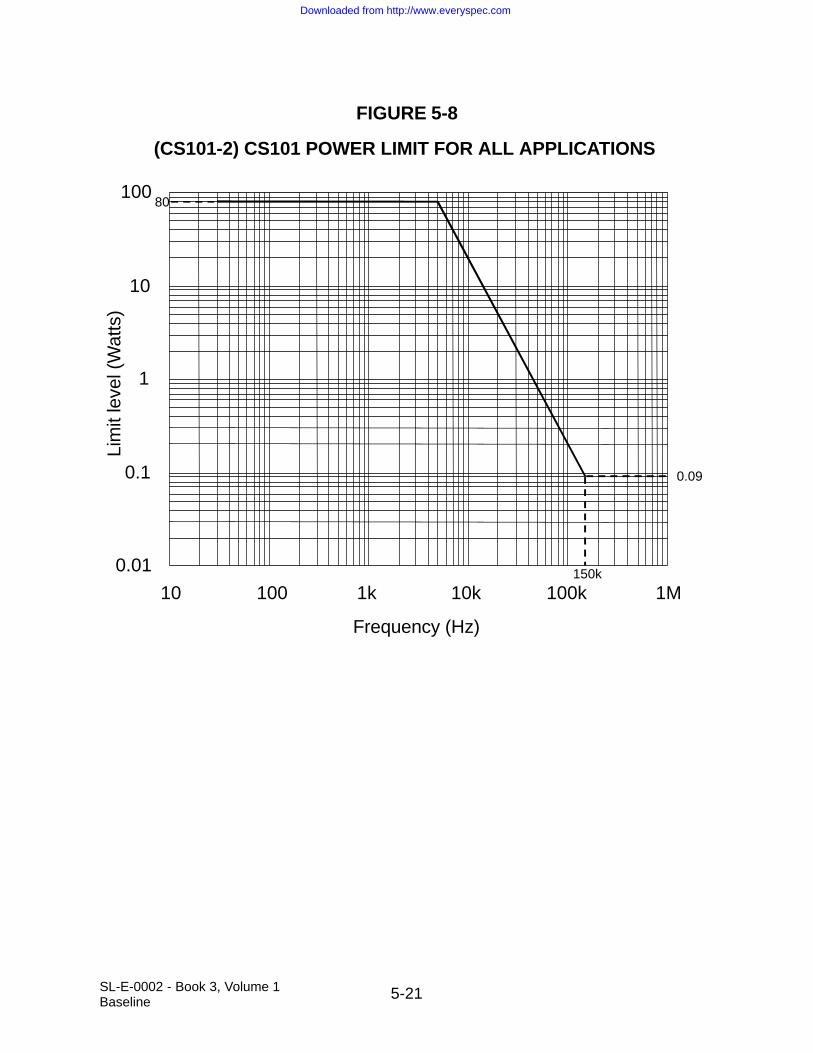
5-21SL-E-0002 - Book 3, Volume 1Baseline
FIGURE 5-8
(CS101-2) CS101 POWER LIMIT FOR ALL APPLICATIONS
0.01
0.1
1
10
100
10 100 1k 10k 100k 1M
Frequency (Hz)
Lim
it le
vel (
Wat
ts)
80
0.09
150k
Downloaded from http://www.everyspec.com

5-22SL-E-0002 - Book 3, Volume 1Baseline
FIGURE 5-9
(CS101-3) CALIBRATION
0.5ΩOscilloscope
SignalGenerator
PowerAmplifier
CouplingTransformer
Downloaded from http://www.everyspec.com

5-23S
L-E-0002 - B
ook 1, Volum
e 1B
aseline
FIGURE 5-10
(CS101-4) SIGNAL INJECTION, DC OR SINGLE PHASE AC
Downloaded from http://www.everyspec.com

5-24S
L-E-0002 - B
ook 1, Volum
e 1B
aseline
FIGURE 5-11
(CS101-5) SIGNAL INJECTION, 3-PHASE UNGROUNDED
Downloaded from http://www.everyspec.com
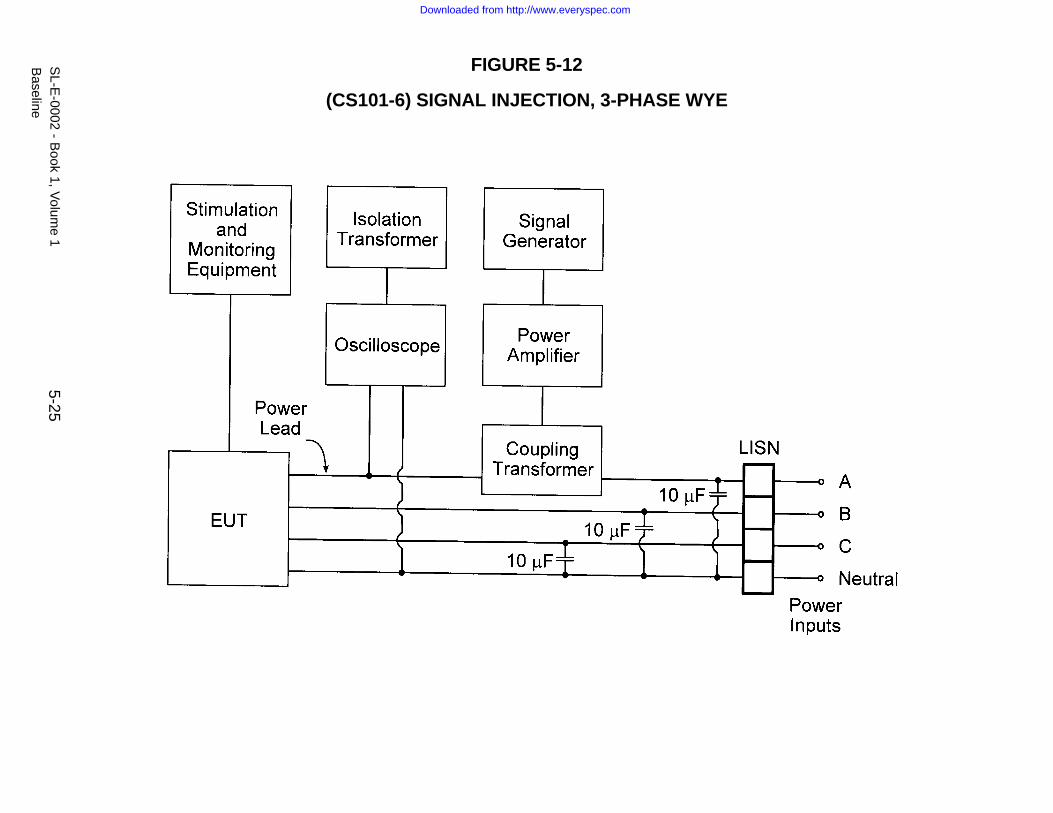
5-25S
L-E-0002 - B
ook 1, Volum
e 1B
aseline
FIGURE 5-12
(CS101-6) SIGNAL INJECTION, 3-PHASE WYE
Downloaded from http://www.everyspec.com
5-26SL-E-0002 - Book 3, Volume 1Baseline
5.5 CS103, CONDUCTED SUSCEPTIBILITY, ANTENNA PORT, INTERMODULATION,15 kHz TO 10 GHz
5.5.1 CS103 Applicability
This receiver front-end susceptibility requirement is applicable to equipment and sub-systems, such as communications receivers, RF amplifiers, transceivers, radarreceivers, acoustic receivers, and electronic warfare receivers as specified in the indi-vidual procurement specification.
5.5.2 CS103 Limit
The EUT shall not exhibit any intermodulation products beyond specified toleranceswhen subjected to the limit requirement provided in the individual procurement specification.
5.5.3 CS103 Test Procedures
5.5.3.1 Purpose
This test procedure is used to determine the presence of intermodulation products thatmay be caused by undesired signals at the EUT antenna input terminals.
5.5.3.2 Test Requirements
The required test equipment, setup, procedures, and data presentation shall be deter-mined on a case-by-case basis in accordance with the guidance provided in AppendixB, Paragraph 5.5.
5.6 CS104, CONDUCTED SUSCEPTIBILITY, ANTENNA PORT, REJECTION OF UNDESIRED SIGNALS, 30 Hz TO 18 GHz
5.6.1 CS104 Applicability
This receiver front-end susceptibility requirement is applicable to equipment and sub-systems, such as communications receivers, RF amplifiers, transceivers, radarreceivers, acoustic receivers, and electronic warfare receivers as specified in the indi-vidual procurement specification.
5.6.2 CS104 Limit
The EUT shall not exhibit any undesired response beyond specified tolerances whensubjected to the limit requirement provided in the individual procurement specification.
Downloaded from http://www.everyspec.com

5-27SL-E-0002 - Book 3, Volume 1Baseline
5.6.3 CS104 Test Procedures
5.6.3.1 Purpose
This test procedure is used to determine the presence of spurious responses that maybe caused by undesired signals at the EUT antenna input terminals.
5.6.3.2 Test Requirements
The required test equipment, setup, procedures, and data presentation shall be determined on a case-by-case basis in accordance with the guidance provided inAppendix B, Paragraph 5.6 of this document.
5.7 CS106, CONDUCTED SUSCEPTIBILITY, ANTENNA PORT, CROSS MODULATION, 30 Hz TO 18 GHz
5.7.1 CS105 Applicability
This receiver front-end susceptibility requirement is applicable only to receivers thatnormally process amplitude-modulated RF signals, as specified in the individual pro-curement specification.
5.7.2 CS105 Limit
The EUT shall not exhibit any undesired response, due to cross modulation, beyondspecified tolerances when subjected to the limit requirement provided in the individualprocurement specification.
5.7.3 CS105 Test Procedures
5.7.3.1 Purpose
This test procedure is used to determine the presence of cross-modulation productsthat may be caused by undesired signals at the EUT antenna terminals.
5.7.3.2 Test Requirements
The required test equipment, setup, procedures, and data presentation shall be deter-mined in accordance with the guidance provided in Appendix B, Paragraph 5.7.
5.8 CS106, CONDUCTED SUSCEPTIBILITY, POWER-LINE SWITCHING TRANSIENTS
5.8.1 CS106 Applicability
This requirement is applicable to equipment and subsystem DC input power leads, notincluding returns.
Downloaded from http://www.everyspec.com
5-28SL-E-0002 - Book 3, Volume 1Baseline
5.8.2 CS106 Limit
The EUT shall not exhibit any malfunction, degradation of performance, or deviationfrom specified indications, beyond the tolerances indicated in the individual equipmentor subsystems specification, when subjected to a pre-calibrated transient having pulsewidth and amplitude as specified in Figure 5-13 at a 1 Hz rate for 1 minute.
5.8.3 CS106 Test Procedures
5.8.3.1 Purpose
This test procedure is used to verify the ability of the EUT to withstand power-line loadinduced switching transients.
5.8.3.2 Test Equipment
The test equipment shall be as follows:
a. Switching transient generator
b. Oscilloscope, 50 ohm input impedance
c. 50 microHenry (µH), 50 ohm line-to-ground LISNs, one in each powerconductor
d. 50 µf capacitor rated above 28 working volts DC (nominal capacitor value)
e. 4 ohm, 1 W resistor (nominal resistance value)
5.8.3.3 Setup
The test setup shall be as follows:
a. Maintain a basic test setup for the EUT as shown and described in Figure 4-1through Figure 4-5 and Paragraph 4.3.8.
b. Calibration. Configure the test equipment in accordance with Figure 5-14 forcalibrating the switching transient.
Set transient generator for “turn-on” (negative polarity) transient. Set pulse rateto nominal 1 Hz rate.
c. EUT Testing. Configure per Figure 5-14 calibration, except that the EUT is nowconnected to power.
5.8.3.4 Procedures
The test procedures shall be as follows:
Downloaded from http://www.everyspec.com

5-29SL-E-0002 - Book 3, Volume 1Baseline
a. Turn on the measurement equipment (oscilloscope) and allow sufficient time forstabilization.
b. Calibration. Perform the following procedures using the calibration setup.
1. Verify that transient amplitude and duration are no less than shown inFigure 5-13.
2. After recording waveforms, shut off transient generator.
c. EUT Testing.
1. Turn on the EUT and allow sufficient time for stabilization.
2. Susceptibility evaluation.
(a) Initiate transient generation. Operate for one minute in negativepolarity mode. Verify proper operation of EUT. Shut down transientgenerator.
(b) Whenever susceptibility is noted, determine the threshold level inaccordance with Paragraph 4.3.10.4.3 and verify that it is above thelimit. Transient duration is modified by changing switched capacitorand/or resistor value. Amplitude cannot be changed. When aResistor/Capacitor (RC) combination is found that yields the thresholdof susceptibility, record the injected waveform as well as the wave-form that combination yields in the pre-calibration setup (EUTdisconnected).
(c) Record samples of transients injected into EUT. These waveformsmay differ from those pre-calibrated.
5.8.3.5 Data Presentation
Data presentation shall be as follows:
a. Oscilloscope traces for pre-calibrated transients.
b. Oscilloscope traces for EUT-injected transients.
c. Provide any susceptibility thresholds and recorded waveforms thereof that weredetermined.
Downloaded from http://www.everyspec.com

5-30SL-E-0002 - Book 3, Volume 1Baseline
FIGURE 5-13
(CS106-1) TRANSIENTS ENVELOPE: 28 VDC BUS, 4//50F LOAD
0
10
20
30
Bus
Pot
entia
l (V
olts
)
–50 0 50 100 150 200 250
Time before and after onset of transient (µs)
Downloaded from http://www.everyspec.com

5-31SL-E-0002 - Book 3, Volume 1Baseline
FIGURE 5-14
(CS106-2) CALIBRATION SETUP
LISNPowerInput
EUT(disconnected)
SwitchingTransientGenerator
Oscilloscope
50 µF
4 Ohms
LISN
Downloaded from http://www.everyspec.com

5-32SL-E-0002 - Book 3, Volume 1Baseline
5.9 CS114, CONDUCTED SUSCEPTIBILITY, BULK CABLE INJECTION, 10 kHz TO 200 MHz
5.9.1 CS114 Applicability
This requirement is applicable to all interconnecting cables, including power cables.
5.9.2 CS114 Limit
The EUT shall not exhibit any malfunction, degradation of performance, or deviationfrom specified indications beyond the tolerances indicated in the individual equipmentor subsystem specification, when subjected to an injection probe drive level which hasbeen pre-calibrated to the current limit shown in Figure 5-15 and is modulated as speci-fied below. Requirements are also met if the EUT is not susceptible at forward powerlevels sensed by the coupler that are below those determined during calibration pro-vided that the actual current induced in the cable under test is 6 dB or greater than thecalibration limit.
5.9.3 CS114 Test Procedures
5.9.3.1 Purpose
This test procedure is used to verify the ability of the EUT to withstand RF signalscoupled onto EUT associated cabling.
5.9.3.2 Test Equipment
The test equipment shall be as follows:
a. Measurement receivers.
b. Current injection probes (maximum insertion loss shown in Figure 5-16,minimum insertion loss is recommended, not required).
c. Current probes.
d. Calibration fixture: coaxial transmission line with 50 ohm characteristic imped-ance, coaxial connections on both ends, and space for an injection probearound the center conductor.
e. Directional couplers.
f. Signal generators.
g. Plotter.
Downloaded from http://www.everyspec.com

5-33SL-E-0002 - Book 3, Volume 1Baseline
h. Attenuators, 50 ohm.
i. Coaxial loads, 50 ohm.
j. Power amplifiers.
k. LISNs.
5.9.3.3 Setup
The test setup shall be as follows:
a. Maintain a basic test setup for the EUT as shown and described in Figure 4-1through Figure 4-5 and Paragraph 4.3.8.
b. Calibration. Configure the test equipment in accordance with Figure 5-17 forcalibrating injection probes.
1. Place the injection probe around the center conductor of the calibration fixture.
2. Terminate one end of the calibration fixture with a 50 ohm load and terminate the other end with an attenuator connected to measurementreceiver A.
c. EUT Testing. Configure the test equipment as shown in Figure 5-18 for testingof the EUT.
1. Place the injection and monitor probes around a cable bundle interfacingwith an EUT connector.
2. Locate the monitor probe 5 cm from the connector. If the overall length ofthe connector and backshell exceeds 5 cm, position the monitor probe asclose to the connector’s backshell as possible.
3. Position the injection probe 5 cm from the monitor probe.
5.9.3.4 Procedures
The test procedures shall be as follows:
a. Turn on the measurement equipment and allow sufficient time for stabilization.
b. Calibration. Perform the following procedures using the calibration setup.
1. Set the signal generator to 10 kHz, unmodulated.
Downloaded from http://www.everyspec.com

5-34SL-E-0002 - Book 3, Volume 1Baseline
2. Increase the applied signal until measurement receiver A indicates the cur-rent level specified in the applicable limit is flowing in the center conductorof the calibration fixture.
3. Record the forward power to the injection probe indicated on measurementreceiver B.
4. Scan the frequency band from 10 kHz to 200 MHz and record the forwardpower needed to maintain the required current amplitude.
c. EUT Testing. Perform the following procedures on each cable bundle inter-facing with each electrical connector on the EUT including complete powercables (high sides and returns). Also perform the procedures on power cableswith the power returns and chassis grounds (green wires) excluded from thecable bundle. For connectors which include both interconnecting leads andpower, perform the procedures on the entire bundle, on the power leads(including returns and grounds) grouped separately, and on the power leadsgrouped with the returns and grounds removed.
1. Turn on the EUT and allow sufficient time for stabilization.
2. Susceptibility evaluation.
(a) Set the signal generator to 10 kHz with 1 kHz pulse modulation, 50%duty cycle.
(b) Apply the forward power level determined under Step b, Item 4(above) to the injection probe while monitoring the induced current.
(c) Scan the required frequency range in accordance with Paragraph4.3.10.4.1 and Table 4.4 while maintaining the forward power level atthe calibration level determined under Step b, Item 4, or the maximumcurrent level for the applicable limit, whichever is less stringent.
(d) Monitor the EUT for degradation of performance during testing.
(e) Whenever susceptibility is noted, determine the threshold level inaccordance with Paragraph 4.3.10.4.3 and verify that it is above theapplicable requirement.
(f) For EUTs with redundant cabling for safety critical reasons such as multiple data buses, use simultaneous multi-cable injectiontechniques.
Downloaded from http://www.everyspec.com

5-35SL-E-0002 - Book 3, Volume 1Baseline
5.9.3.5 Data Presentation
Data presentation shall be as follows:
a. Provide amplitude versus frequency plots for the forward power levels required toobtain the calibration level as determined in Paragraph 5.9.3.4, Step b, Item 4.
b. Provide tables showing scanned frequency ranges and statements of com-pliance with the requirements for the susceptibility evaluation of Paragraph5.9.3.4, Step c, Item 2, for each interface connector. Provide any susceptibilitythresholds that were determined, along with their associated frequencies.
Downloaded from http://www.everyspec.com

5-36S
L-E-0002 - B
ook 3 , Volum
e 1B
aseline
FIGURE 5-15
(CS114-1) CS114 CALIBRATION LIMIT
Downloaded from http://www.everyspec.com

5-37SL-E-0002 - Book 3, Volume 1Baseline
FIGURE 5-16
(CS114-2) MAXIMUM INSERTION LOSS FOR INJECTION PROBES
0
5
10
15
20
25
30
35
40
0.01 0.1 1 10 100 1000
Frequency (MHz)
Inse
rtio
n Lo
ss (
dB)
Maximum Insertion Loss
Recommended MinimumInsertion Loss
Downloaded from http://www.everyspec.com

5-38SL-E-0002 - Book 3, Volume 1Baseline
FIGURE 5-17
(CS114-3) CALIBRATION SETUP
MeasurementReceiver
A
MeasurementReceiver
B
Amplifier
SignalGenerator
Coaxial Load
InjectionProbe
CalibrationFixtureAttenuator
DirectionalCoupler
Downloaded from http://www.everyspec.com

5-39SL-E-0002 - Book 3, Volume 1Baseline
FIGURE 5-18
(CS114-4) BULK CABLE INJECTION EVALUATION
5 cm
5 cm
Actual or SimulatedLoads and Signals
InterconnectingCables
PowerInput
MonitorProbe
InjectionProbe
MonitorProbe
5 cmInjectionProbe
5 cm
LISN
MeasurementReceiver
B
DirectionalCoupler Amplifier
SignalGenerator
MeasurementReceiver
A
EUT
Downloaded from http://www.everyspec.com

5-40SL-E-0002 - Book 3, Volume 1Baseline
5.10 CS116, CONDUCTED SUSCEPTIBILITY, DAMPED SINUSOIDAL TRANSIENTS,CABLES AND POWER LEADS, 10 kHz TO 10 MHz
5.10.1 CS116 Applicability
This requirement is applicable to all interconnecting cables, including power cables,and individual high side power leads. Power returns and neutrals need not be testedindividually.
5.10.2 CS116 Limit
The EUT shall not exhibit any malfunction, degradation of performance, or deviationfrom specified indications, beyond the tolerances indicated in the individual equipmentor subsystem specification, when subjected to a signal having the waveform shown inFigure 5-19 and having a maximum current as specified in Figure 5-20. The limit isapplicable across the entire specified frequency range. As a minimum, complianceshall be demonstrated at the following frequencies: 0.01, 0.1, 1, and 10 MHz. If thereare other frequencies known to be critical to the equipment installation, such as plat-form resonances, compliance shall also be demonstrated at those frequencies. Thetest signal repetition rate shall be no greater than one pulse per second (pps) and noless than one pulse every two seconds. The pulses shall be applied for a period of fiveminutes.
5.10.3 CS116 Test Procedures
5.10.3.1 Purpose
This test procedure is used to verify the ability of the EUT to withstand damped sinu-soidal transients coupled onto EUT associated cables and power leads.
5.10.3.2 Test Equipment
The test equipment shall be as follows:
a. Damped sinusoid transient generator, three 100 ohm output impedance.
b. Current injection probe.
c. Oscilloscope, 50 ohm input impedance.
d. Calibration fixture: Coaxial transmission line with 50 ohm characteristic imped-ance, coaxial connections on both ends, and space for an injection probearound the center conductor.
e. Current probes.
Downloaded from http://www.everyspec.com

5-41SL-E-0002 - Book 3, Volume 1Baseline
f. Waveform recording device.
g. Attenuators, 50 ohm.
h. Measurement receivers.
i. Power amplifiers.
j. Coaxial loads, 50 ohm.
k. Signal generators.
l. Directional couplers.
m. LISNs.
5.10.3.3 Setup
The test setup shall be as follows:
a. Maintain a basic test setup for the EUT as shown and described in Figure 4-1through Figure 4-5 and Paragraph 4.3.8.
b. Calibration. Configure the test equipment in accordance with Figure 5-20 forverification of the waveform.
c. EUT Testing:
1. Configure the test equipment as shown in Figure 5-21.
2. Place the injection and monitor probes around a cable bundle interfacingan EUT connector.
3. Locate the monitor probe 5 cm from the connector. If the overall length ofthe connector and backshell exceeds 5 cm, position the monitor probe asclose to the connector’s backshell as possible.
4. Position the injection probe 5 cm from the monitor probe.
5.10.3.4 Procedures
The test procedures shall be as follows:
a. Turn on the measurement equipment and allow sufficient time for stabilization.
b. Calibration. Perform the following procedures using the calibration setup forwaveform verification.
Downloaded from http://www.everyspec.com

5-42SL-E-0002 - Book 3, Volume 1Baseline
1. Set the frequency of the damped sine generator at 10 kHz.
2. Adjust the amplitude of the signal from the damped sine generator to thelevel specified in the requirement.
3. Record the damped sine generator settings.
4. Verify that the waveform complies with the requirements.
5. Repeat Items 2 through 4 (above) for each frequency specified in therequirement and those identified in Step c, Item 2 (below).
c. EUT testing. Perform the following procedures, using the EUT test setup oneach cable bundle interfacing with each connector on the EUT including com-plete power cables. Also perform tests on each individual high side power lead(individual power returns and neutrals are not required to be tested).
1. Turn on the EUT and measurement equipment to allow sufficient time forstabilization.
2. Set the damped sine generator to a test frequency.
3. Apply the test signals to each cable or power lead of the EUT sequentially.Slowly increase the damped sinewave generator output level to provide thespecified current, but not exceeding the precalibrated generator outputlevel. Record the peak current obtained.
4. Monitor the EUT for degradation of performance.
5. If susceptibility is noted, determine the threshold level in accordance withParagraph 4.3.10.4.3 and verify that it is above the specified requirements.
6. Repeat Items 2 through 5 (above) for each test frequency as specified inthe requirement. Repeat testing in Step c for the power-off condition.
5.10.3.5 Data Presentation
Data presentation shall be as follows:
a. Provide a list of the frequencies and amplitudes at which the test was con-ducted for each cable and lead.
b. Provide data on any susceptibility thresholds and the associated frequenciesthat were determined for each connector and power lead.
c. Provide indications of compliance with the requirements for the susceptibility eval-uation specified in Paragraph 5.10.3.4, Step c, for each interface connector.
d. Provide oscilloscope photographs of injected waveforms with test data.
Downloaded from http://www.everyspec.com

5-43SL-E-0002 - Book 3, Volume 1Baseline
FIGURE 5-19
(CS116-1) TYPICAL CS116 DAMPED SINUSOIDAL WAVEFORM
Downloaded from http://www.everyspec.com

5-44SL-E-0002 - Book 3, Volume 1Baseline
FIGURE 5-20
(CS116-2) CS116 LIMIT FOR ALL APPLICATIONS
0.01IMAX
0.1I
IMAX
10 I MAX
Frequency (Hz)
I P
I max = 0.5 Amp
MAX
1 k 10 k 100 k 1 M 10 M 100 M
Downloaded from http://www.everyspec.com

5-45SL-E-0002 - Book 3, Volume 1Baseline
FIGURE 5-21
(CS116-3) TYPICAL TEST SETUP FOR CALIBRATION OF TEST WAVEFORM
StorageOscilloscope
Coaxial Load
InjectionProbe
CalibrationFixture
Attenuator
Damped SinusoidTransient Generator
Downloaded from http://www.everyspec.com

5-46SL-E-0002 - Book 3, Volume 1Baseline
FIGURE 5-22(CS116-4) TYPICAL SET UP FOR BULK CABLE INJECTION OF
DAMPED SINUSOIDAL TRANSIENTS
5 cm
5 cm
Actual or SimulatedLoads and Signals
InterconnectingCables
PowerInput
MonitorProbe
InjectionProbe
MonitorProbe
5 cmInjectionProbe
5 cm
LISN
DampedSinusoid
Generator
StorageOscilloscope
EUT
Downloaded from http://www.everyspec.com

5-47SL-E-0002 - Book 3, Volume 1Baseline
5.11 RE102, RADIATED EMISSIONS, ELECTRIC FIELD, 150 kHz TO 18 GHz
5.11.1 RE102, Applicability
This requirement is applicable for REs from equipment and subsystem enclosures,all interconnecting cables including power leads, and antennas designed to be per-manently mounted to EUTs (receivers and transmitters in standby mode). Therequirement does not apply at the transmitter fundamental frequencies. The require-ment is applicable as follows:
a. Space Shuttle BCE - 150 kHz to 200 MHz
b. Space Shuttle (including ground support equipment) REs - 200 MHz - 18 GHz*
*Testing is required up to 1 GHz or 10 times the highest intentionally generated frequency within the EUT, whichever is greater. Measurements beyond 18 GHzare not required.
5.11.2 RE102 Limits
Electric field emissions shall not be radiated in excess of those shown in Figure 5-23through Figure 5-26 as defined in the following subsections. Above 200 MHz, the limitsshall be met for both horizontally and vertically polarized fields, when the receiveantenna is polarized. Circularly polarized antennas are also acceptable. For SpaceShuttle applications, the RE102 limits of Figure 5-23 through Figure 5-25 are applicableas define above 200 MHz as specified in the following sections. The RE limit below200 MHz is defined by Figure 5-26 for all applications.
5.11.2.1 Internal Equipment Installation Limits
Equipment located internal to the SSV shall meet the limit depicted in Figure 5-23.
Equipment that meets all of the following criteria may use the limit depicted in Figure 5-24.
a. The equipment is located internal to the SSV.
b. The equipment is designated as Criticality 3 or non-critical allowing it to beturned off if interference arises from its operation.
c. The equipment is not operated on the flight deck during launch and entryoperational phases.
d. The equipment is not permanently manifested.
Reference Appendix B, Paragraph 5.11 for a discussion as to why the limit depicted inFigure 5-24 is acceptable only for equipment that meets all the defined criteria.
Downloaded from http://www.everyspec.com

5-48SL-E-0002 - Book 3, Volume 1Baseline
5.11.2.2 External Equipment Installation Limits
Equipment installed externally to the SSV shall meet the limit depicted in Figure 5-25(reference definition in Paragraph 3.1).
5.11.3 RE102 Test Procedures
5.11.3.1 Purpose
This test procedure is used to verify that electric field emissions from the EUT and itsassociated cabling do not exceed specified requirements. The BCE portion of therequirement for Space Shuttle protects against cable-to-cable crosstalk out of band toShuttle radio receivers.
5.11.3.2 Test Equipment
The test equipment shall be as follows:
a. Measurement receivers
b. Data recording device
c. Antennas
1. 200 MHz to 1 GHz, logconical, logperiodic, or -double ridge horn, 69.0 by94.5 cm opening
2. One GHz to 18 GHz, double ridge horn, 24.2 by 13.6 cm opening
3. One GHz to 10 GHz, logconical may be used in this band, if desired
d. Signal generators
e. Stub radiator
f. LISNs
g. Absorbing clamp (per CISPR 16, Specification for radio disturbance and immunity measuring apparatus and methods)
NOTE: Absorbing clamp must be calibrated as a current probe, not per CISPR 16.
5.11.3.3 Setup
The test setup shall be as follows:
a. Maintain a basic test setup for the EUT as shown and described in Figure 4-1through Figure 4-5 and Paragraph 4.3.8. Ensure that the EUT is oriented such
Downloaded from http://www.everyspec.com
5-49SL-E-0002 - Book 3, Volume 1Baseline
that the surface that produces the maximum REs is toward the front edge of thetest setup boundary.
b. Calibration. For radiated calibration, configure the test equipment as shown inFigure 5-27. For BCE testing, configure per Figure 5-28.
c. EUT testing.
1. Antenna positioning.
(a) Determine the test setup boundary of the EUT and associated cablingfor use in positioning of antennas.
(b) Use the physical reference points on the antennas shown in Figure5-30 for measuring heights of the antennas and distances of theantennas from the test setup boundary.
(1) Position antennas 1 meter from the front edge of the test setupboundary for all setups.
(2) Position antennas 120 cm above the floor ground plane.
(3) Ensure that no part of any antenna is closer than 1 meter fromthe walls and 0.5 meter from the ceiling of the shieldedenclosure.
(4) For test setups using bench tops, additional positioning require-ments for the antenna and distance above the bench groundplane are shown in Figure 5-30.
2. The number of required antenna positions depends on the size of the testsetup boundary and the number of enclosures included in the setup (refer-ence Figure 5-31).
(a) For testing from 200 MHz up to 1 GHz, place the antenna in a suffi-cient number of positions such that the entire width of each EUTenclosure and the first 35 cm of cables and leads interfacing with theEUT enclosure are within the 3 dB beamwidth of the antenna.
(b) For testing at 1 GHz and above, place the antenna in a sufficientnumber of positions such that the entire width of each EUT enclosureand the first 7 cm of cables and leads interfacing with the EUT enclo-sure are within the 3 dB beamwidth of the antenna.
5.11.3.4 Procedures
The test procedures shall be as follows:
Downloaded from http://www.everyspec.com

5-50SL-E-0002 - Book 3, Volume 1Baseline
a. Verify that the ambient requirements specified in Paragraph 4.3.4 are met.Take plots of the ambient when required by the referenced paragraph.
b. Turn on the measurement equipment and allow a sufficient time for stabilization.
c. Using the system check path of Figure 5-27, perform the following evaluation ofthe overall measurement system from each antenna to the data output deviceat the highest measurement frequency of the antenna.
1. Apply a calibrated signal level, which is at least 6 dB below the limit (limitminus antenna factor), to the coaxial cable at the antenna connection point.For the BCE calibration, set signal generator to a potential which will yield acurrent flow at 6 dB below the limit at 150 kHz, 10 MHz, and 200 MHz.
2. Scan the measurement receiver in the same manner as a normal datascan. Verify that the data recording device indicates a level within ±3 dB ofthe injected signal level.
3. If readings are obtained which deviate by more than ±3 dB, locate thesource of the error and correct the deficiency prior to proceeding with thetesting.
d. Using the measurement path of Figure 5-27, perform the following evaluationfor each antenna to demonstrate that there is electrical continuity through theantenna.
1. Radiate a signal using an antenna or stub radiator at the highest measure-ment frequency of each antenna.
2. Tune the measurement receiver to the frequency of the applied signal andverify that a received signal of appropriate amplitude is present.
NOTE: This evaluation is intended to provide a coarse indication that theantenna is functioning properly. There is no requirement to accuratelymeasure the signal level.
e. Turn on the EUT and allow sufficient time for stabilization.
f. Using the measurement path of Figure 5-27, determine the REs from the EUTand its associated cabling. Using the setup of Figure 5-29, measure commonmode emissions on all EUT attached cables (both power and signal).
NOTE: Both power conductors are tested together to ensure that only commonmode power-line CEs are measured.
1. Scan the measurement receiver for each applicable frequency range, usingthe BWs and minimum measurement times in Table 4.3.
Downloaded from http://www.everyspec.com

5-51SL-E-0002 - Book 3, Volume 1Baseline
2. Orient antennas for both horizontally and vertically polarized fields.
3. Take measurements for each antenna position determined under Para-graph 5.11.3.3, Step 3, Item b (above).
5.11.3.5 Data Presentation
Data presentation shall be as follows:
a. Continuously and automatically plot amplitude versus frequency profiles.Manually gathered data is not acceptable except for plot verification. Verticaland horizontal data for a particular frequency range shall be presented on sep-arate plots or shall be clearly distinguishable in black or white format for acommon plot.
b. Display the applicable limit on each plot.
c. Provide a minimum frequency resolution of 1% or twice the measurementreceiver BW, whichever is less stringent, and a minimum amplitude resolutionof 1 dB for each plot.
d. Provide plots for both the measurement and system check portions of the pro-cedure.
e. Provide a statement verifying the electrical continuity of the measurementantennas as determined in Paragraph 5.11.3.4, Step d.
Downloaded from http://www.everyspec.com

5-52SL-E-0002 - Book 3, Volume 1Baseline
FIGURE 5-23
(RE102-1A) RE102 LIMIT FOR INTERNAL EQUIPMENT
40
50
60
70
80
90
100 1000 10000
Frequency MHz 18 GHz
89
Ele
ctri
c Fi
eld
Inte
nsity
, dB
V/m
Downloaded from http://www.everyspec.com

5-53SL-E-0002 - Book 3, Volume 1Baseline
FIGURE 5-24
(RE102-1B) RE102 LIMIT FOR INTERNAL EQUIPMENT THAT MEETSALL THE CRITERIA OF SECTION 5.11.2.1
60
70
80
90
100 1000 10000
Frequency MHz 18 GHz
89
2300
72
66
Ele
ctri
c Fi
eld
Inte
nsity
, dB
V/m
Downloaded from http://www.everyspec.com

5-54SL-E-0002 - Book 3, Volume 1Baseline
FIGURE 5-25
(RE102-1C) RE102 LIMIT FOR EXTERNAL EQUIPMENT
20
30
40
50
60
70
80
0.1 1 10
Frequency GHz
69
18 GHz
Ele
ctri
c Fi
eld
Inte
nsity
, dB
V/m
Downloaded from http://www.everyspec.com

5-55SL-E-0002 - Book 3, Volume 1Baseline
FIGURE 5-26
(RE102-1D) BCE LIMIT FOR SPACE SHUTTLE APPLICATIONS
20
30
40
50
60
70
80
BC
E li
mit
dBµA
0.1 1 10 100
Frequency MHz
(0.15 MHz, 77 dBµA)
Downloaded from http://www.everyspec.com

5-56SL-E-0002 - Book 3, Volume 1Baseline
FIGURE 5-27
(RE102-2) BASIC TEST SETUP
SignalGenerator
Path forSystem Check
TEST SETUP BOUNDARY
Path forMeasurement
MeasurementReceiver
DataRecording
Device
Shielded Enclosure
Antenna
CoaxialCable
Downloaded from http://www.everyspec.com

5-57SL-E-0002 - Book 3, Volume 1Baseline
FIGURE 5-28
(RE102-2A) BASIC BCE CALIBRATION TEST SETUP
rf signalgenerator
50CISPR 16 absorbing clamp
Coax to EMI Receiver
Single Wire Above Ground
rf SignalGenerator
50 OhmsCISPR 16 Absorbing Clamp
Downloaded from http://www.everyspec.com

5-58SL-E-0002 - Book 3, Volume 1Baseline
FIGURE 5-29
(RE102-2B) BCE TEST SETUP
Signal Bundle
Power and Return
EMI
RecordingDevice
Absorbing Clamp
LISN LISN
< 15 cm
< 15 cm
Absorbing Clamp
EUT
Receiver
Downloaded from http://www.everyspec.com

5-59SL-E-0002 - Book 3, Volume 1Baseline
FIGURE 5-30
(RE102-3) ANTENNA POSITIONINGNOTE: The rod and biconical antenna configurations are not required for SSV testing.
Downloaded from http://www.everyspec.com

5-60S
L-E-0002 - B
ook 3, Volum
e 1B
aseline
FIGURE 5-31
(RE102-4) MULTIPLE ANTENNA POSITIONS
Downloaded from http://www.everyspec.com

5-61SL-E-0002 - Book 3, Volume 1Baseline
5.12 RE103, RADIATED EMISSIONS, ANTENNA SPURIOUS AND HARMONIC OUTPUTS,100 MHz TO 18 GHz
5.12.1 RE103 Applicability
This requirement may be used as an alternative for CE106 when testing transmitterswith their intended antennas. The requirement is not applicable within the EUT neces-sary BW and within ±5 percent of the fundamental frequency. Depending on theoperating frequency range of the EUT, the start frequency is 100 MHz for all EUT oper-ating frequency ranges. The end frequency of the test is 18 GHz or twenty times thehighest generated frequency within the EUT, whichever is less. For equipment usingwaveguide, the requirement does not apply below eight-tenths of the waveguide’s cutofffrequency.
5.12.2 RE103 Limits
Harmonics, except the second and third, and all other spurious emissions shall be atleast 80 dB down from the level at the fundamental. The second and third harmonicsshall be suppressed 50 + 10 log p (where p = peak power output in watts, at the funda-mental) or 80 dB, whichever requires less suppression.
5.12.3 RE103 Test Procedures
5.12.3.1 Purpose
This test procedure is used to verify that radiated spurious and harmonic emissionsfrom transmitters do not exceed the specified requirements.
5.12.3.2 Test Equipment
The test equipment shall be as follows:
a. Measurement receiver
b. Attenuators, 50 ohm
c. Antennas
d. Rejection networks
e. Signal generators
f. Power monitor
5.12.3.3 Setup
It is not necessary to maintain the basic test setup for the EUT as shown and described inFigure 4-1 through Figure 4-5 and Paragraph 4.3.8. The test setup shall be as follows:
Downloaded from http://www.everyspec.com

5-62SL-E-0002 - Book 3, Volume 1Baseline
a. Calibration. Configure the test setup for the signal check path shown in Figure5-32 or Figure 5-33, as applicable.
b. EUT Testing. Configure the test setup for the measurement path shown inFigure 5-32 or Figure 5-33, as applicable.
5.12.3.4 Procedures
The test procedures shall be as follows:
a. The measurements must be performed in the far-field of the transmitting fre-quency. Consequently, the far-field test distance must be calculated prior toperforming the test using the relationships below:
R = distance between transmitter antenna and receiver antenna.
D = maximum physical dimension of transmitter antenna.
d = maximum physical dimension of receiver antenna.
λ = wavelength of frequency of the transmitter.
All dimensions are in meters.
For transmitter frequencies less than or equal to 1.24 GHz, the greater distanceof the following relationships shall be used:
R = 2D2/λ R = 3λ
For transmitter frequencies greater than 1.24 GHz, the separation distanceshall be calculated as follows:
For 2.5 D < d use R = 2D2/λ
For 2.5 D ≥ d use R = (D+d)2/λ
b. Turn on the measurement equipment and allow sufficient time for stabilization.
c. Calibration.
1. Apply a known calibrated signal level from the signal generator through thesystem check path at a midband fundamental frequency (fo).
2. Scan the measurement receiver in the same manner as a normal datascan. Verify the measurement receiver detects a level within ±3 dB of theexpected signal.
3. If readings are obtained which deviate by more than ±3 dB, locate thesource of the error and correct the deficiency prior to proceeding with thetest.
4. Repeat Items 1 through 4 (above) for two other frequencies over the fre-quency range of test.
Downloaded from http://www.everyspec.com

5-63SL-E-0002 - Book 3, Volume 1Baseline
d. EUT Testing.
1. Turn on the EUT and allow a sufficient time for stabilization.
2. Tune the EUT to the desired test frequency and use the measurement pathto complete the rest of this procedure.
3. Tune the test equipment to the measurement frequency (fo) of the EUT andadjust for maximum indication.
4. For transmitters where a power monitor can be inserted, measure the mod-ulated transmitter power output P, using a power monitor while keying thetransmitter. Convert this power level to units of dB relative to 1 watt (dec-ible watt [dBW]). Calculate the Effective Radiated Power (ERP) by addingthe EUT antenna gain to this value. Record the resulting level for compar-ison with that obtained in Item 6 (below).
5. Key the transmitter with desired modulation. Tune the measurementreceiver for maximum output indication at the transmitted frequency. Ifeither or both of the antennas have directivity, align both in elevation andazimuth for maximum indication. Verbal communication between sites viaradiotelephone will facilitate this process. Record the resulting maximumreceiver meter reading and the measurement receiver BW.
6. Calculate the transmitter ERP in dBW, based on the receiver meter readingV, using the following equation:
ERP = V + 20 log R + AF - 135
where:
V = reading on the measurement receiver in dBµV
R = distance between transmitter and receiver antennas in meters
AF = antenna factor of receiver antenna in dB (1/m)
Compare this calculated level to the measured level recorded in Item 4 (above).The compared results should agree within ±3 dB. If the difference exceeds±3 dB, check the test setup for errors in measurement distance, amplitude cal-ibration, power monitoring of the transmitter, frequency tuning or drift andantenna boresight alignment. Assuming that the results are within the ±3 dBtolerance, the ERP becomes the reference for which amplitudes of spuriousand harmonics will be compared to determine compliance with standard limits.
7. With the rejection network filter connected and tuned to fo, scan the mea-surement receiver over the frequency range of test to locate spurious and
Downloaded from http://www.everyspec.com

5-64SL-E-0002 - Book 3, Volume 1Baseline
harmonic transmitted outputs. It may be necessary to move the measuringsystem antenna in elevation and azimuth at each spurious and harmonicoutput to assure maximum levels are recorded. Maintain the same mea-surement receiver BW used to measure the fundamental frequency in Item5 (above).
8. Verify that spurious outputs are from the EUT and not spurious responsesof the measurement system or the test site ambient.
9. Calculate the ERP of each spurious output. Include all correction factorsfor cable loss, amplifier gains, filter loss, and attenuator factors.
10. Repeat Items 2 through 9 (above) for other fo of the EUT.
5.12.3.5 Data Presentation
Data presentation shall be as follows:
Provide tabular data showing fundamental frequency (fo) and frequency of all har-monics and spurious emissions measured, the measured power monitor level and thecalculated ERP of the fundamental frequency, the ERP of all spurious and harmonicsemissions measured, dB down levels, and all correction factors including cable loss,attenuator pads, amplifier gains, insertion loss of rejection networks and antenna gains.
The relative dB down level is determined by subtracting the level in Paragraph 5.12.4,Step d, Item 6, from that recorded in Paragraph 5.12.4, Step d, Item 9.
Downloaded from http://www.everyspec.com

5-65SL-E-0002 - Book 3, Volume 1Baseline
FIGURE 5-32
(RE103-1) CALIBRATION AND TEST SETUP FOR RADIATED HARMONICS AND SPURIOUS EMISSIONS, 100 MHz TO 1 GHz
RX AntennaTX AntennaPath for Measurement
TransmitterEUT
Path for Band Rejectionor
High Pass Filter
SignalGenerator
Attenuator
MeasurementReceiver
PowerMonitor
SystemCheck
Downloaded from http://www.everyspec.com

5-66SL-E-0002 - Book 3, Volume 1Baseline
FIGURE 5-33
(RE103-2) CALIBRATION AND TEST SETUP FOR RADIATED HARMONICS AND SPURIOUS EMISSIONS, 1 GHz TO 18 GHz
RX AntennaTX Antenna Path for Measurement
TransmitterEUT
Path forSystemCheck
Band Rejectionor
High Pass Filter
SignalGenerator
VariableAttenuator
Preselectoror Filter
MeasurementReceiver
PowerMonitor
Downloaded from http://www.everyspec.com

5-67SL-E-0002 - Book 3, Volume 1Baseline
5.13 RS103, RS, ELECTRIC FIELD, 30 MHz TO 18 GHz
5.13.1 RS103 Applicability
This requirement is applicable to equipment and subsystem enclosures and all inter-connecting cables. The requirement is applicable as follows:
a. 30 MHz to 18 GHz
b. 18 GHz to 40 GHz - optional*
*Required only if specified in the procurement specification
The requirement at the tuned frequency of an antenna-connected receiver is 20 dBabove the RE102 limit associated with the particular platform application, with theantenna port dummy loaded and shielded.
5.13.2 RS103 Limit
The EUT shall not exhibit any malfunction, degradation of performance, or deviationfrom specified indications, beyond the tolerances indicated in the individual equipmentor subsystem specification, when subjected to the radiated electric fields listed in Table5.1 or Table 5.2 (as applicable) and modulated as specified below the tables. EMC crit-ical equipment is defined in SL-E-0001, Specification Electromagnetic CompatibilityRequirement. The requirement shall be met for both horizontally and vertically polar-ized fields. Circularly polarized fields are not acceptable.
TABLE 5.2
(RS103-1) RS103 LIMITS FOR EMC CRITICAL EQUIPMENT(AS DEFINED IN SL-E-0001)
FrequencyTest Level (V/m)
Square Wave ModulationTest Level (V/m)
Low prf Pulse Modulation
30 MHz - 1 GHz 20 N/A
1 - 18 GHz N/A 200
Downloaded from http://www.everyspec.com

5-68SL-E-0002 - Book 3, Volume 1Baseline
TABLE 5.3
(RS103-2) RS103 LIMITS FOR NON-EMC CRITICAL EQUIPMENT
FrequencyTest Level (V/m)
Square Wave ModulationTest Level (V/m)
Low prf Pulse Modulation
30 MHz - 18 GHz 20 N/A
50% duty cycle pulse or amplitude modulation: use 1 kHz, 50% duty cycle pulse modu-lation with at least 40 dB on/off ratio, or square wave amplitude modulation with at least99% depth.
Low pulse repetition frequency (prf) pulse modulation: use a 4 microsecond pulse at a1 kHz prf from 1 to 18 GHz.
5.13.3 RS103 Test Procedures
5.13.3.1 Purpose
This test procedure is used to verify the ability of the EUT and associated cabling towithstand electric fields.
5.13.3.2 Test Equipment
The test equipment shall be as follows:
a. Signal generators
b. Power amplifiers
c. Receive antennas
1. 1 GHz to 10 GHz, double ridge horns
2. 10 GHz to 40 GHz, other antennas as approved by the procuring activity
d. Transmit antennas
e. Electric field sensors (physically small - electrically short)
f. Measurement receiver
g. Power meter
h. Directional coupler
i. Attenuator
Downloaded from http://www.everyspec.com

5-69SL-E-0002 - Book 3, Volume 1Baseline
j. Data recording device
k. LISNs
5.13.3.3 Setup
The test setup shall be as follows:
a. Maintain a basic test setup for the EUT as shown and described in Figure 4-1through Figure 4-5 and Paragraph 4.3.8.
b. For electric field calibration, electric field sensors are required from 100 MHz to1 GHz. Either field sensors or receive antennas may be used above 1 GHz(reference Paragraph 5.13.3.2, Step c and Step e).
c. Configure test equipment as shown in Figure 5-34.
d. Calibration.
1. Placement of electric field sensors (reference Step b [above]). Positionsensors 1 meter from, and directly opposite, the transmit antenna as shown in Figure 5-35 and Figure 5-36 and a minimum of 30 cm above theground plane. Do not place sensors directly at corners or edges of EUTcomponents.
2. Placement of receive antennas (reference Step b [above]). Prior to place-ment of the EUT, position the receive antenna, as shown in Figure 5-37, ona dielectric stand at the position and height above the ground plane wherethe center of the EUT will be located.
e. EUT testing.
1. Placement of transmit antennas. Antennas shall be placed 1 meter fromthe test setup boundary as follows:
(a) 30 MHz to 200 MHz
(1) Test setup boundaries ≤ 3 meters. Center the antenna betweenthe edges of the test setup boundary. The boundary includes allenclosures of the EUT and the 2 meters of exposed intercon-necting and power leads required in Paragraph 4.3.8.6.Interconnecting leads shorter than 2 meters are acceptablewhen they represent the actual platform installation.
(2) Test setup boundaries > 3 meters. Use multiple antenna posi-tions (N) at spacings as shown in Figure 5-36. The number ofantenna positions (N) shall be determined by dividing the edge-to-edge boundary distance (in meters) by 3 and rounding up toan integer.
Downloaded from http://www.everyspec.com

5-70SL-E-0002 - Book 3, Volume 1Baseline
(b) 200 MHz and above. Multiple antenna positions may be required asshown in Figure 5-35. Determine the number of antenna positions(N) as follows:
(1) For testing from 200 MHz up to 1 GHz, place the antenna in asufficient number of positions such that the entire width of eachEUT enclosure and the first 35 cm of cables and leads inter-facing with the EUT enclosure are within the 3 dB beamwidth ofthe antenna.
(2) For testing at 1 GHz and above, place the antenna in a sufficientnumber of positions such that the entire width of each EUTenclosure and the first 7 cm of cables and leads interfacing withthe EUT enclosure are within the 3 dB beamwidth of theantenna.
2. Maintain the placement of electric field sensors as specified in Step d, Item 1 (above).
5.13.3.4 Procedures
The test procedures shall be as follows:
a. Turn on the measurement equipment and EUT and allow a sufficient time forstabilization.
b. Assess the test area for potential RF hazards and take necessary precau-tionary steps to assure safety of test personnel.
c. Calibration.
1. Electric field sensor procedure. Record the amplitude shown on the elec-tric field sensor display unit due to EUT ambient. Reposition the sensor, asnecessary, until this level is < 10% of the applicable field strength to beused for testing.
2. Receive antenna procedure (> 1 GHz).
(a) Connect a signal generator to the coaxial cable at the receive antennaconnection point (antenna removed). Set the signal source to anoutput level of 0 decibel milliWatt (dBm) at the highest frequency to beused in the present test setup. Tune the measurement receiver to thefrequency of the signal source.
(b) Verify that the output indication is within ±3 dB of the applied signal,considering all appropriate losses. If larger deviations are found,locate the source of the error and correct the deficiency before proceeding.
Downloaded from http://www.everyspec.com

5-71SL-E-0002 - Book 3, Volume 1Baseline
(c) Connect the receive antenna to the coaxial cable as shown in Figure5-37. Set the signal source to the applicable modulation noted inTable 5.1 or Table 5.2. Using an appropriate transmit antenna andamplifier, establish an electric field at the test start frequency. Gradu-ally increase the electric field level until it reaches the applicable limit.
(d) Scan the test frequency range and record the required input powerlevels to the transmit antenna to maintain the required field.
(e) Repeat procedures Step c, Item 2a through Step c, Item 2d (above)whenever the test setup is modified or an antenna is changed.
3. EUT Testing.
(a) E-Field sensor procedure.
(1) Set the signal source to the applicable modulation as noted inTable 5.1 or Table 5.2 and using appropriate amplifier andtransmit antenna, establish an electric field at the test start fre-quency. Gradually increase the electric field level until it reachesthe applicable limit.
(2) Scan the required frequency ranges in accordance with the ratesand durations specified in Table 4.4. Maintain field strengthlevels in accordance with the applicable limit. Monitor EUT per-formance for susceptibility effects.
(b) Receive antenna procedure.
(1) Remove the receive antenna and reposition the EUT in confor-mance with Paragraph 5.13.3.3, Step a.
(2) Set the signal source to the applicable modulation noted in Table5.1 or Table 5.2. Using an appropriate amplifier and transmitantenna, establish an electric field at the test start frequency.Gradually increase the input power level until it corresponds tothe applicable level recorded during the calibration routine.
(3) Scan the required frequency range in accordance with the ratesand durations specified in Table 4.4 while assuring the correcttransmitter input power is adjusted in accordance with the cal-ibration data collected. Constantly monitor the EUT forsusceptibility conditions.
(c) If susceptibility is noted, determine the threshold level in accordancewith Paragraph 4.3.10.4.3 and verify that it is above the limit.
Downloaded from http://www.everyspec.com

5-72SL-E-0002 - Book 3, Volume 1Baseline
(d) Perform testing over the required frequency range with the transmitantenna vertically polarized. Repeat the testing with the transmitantenna horizontally polarized.
(e) Repeat Step d (above) for each transmit antenna position required byParagraph 5.13.3.3, Step e.
5.13.3.5 Data Presentation
Data presentation shall be as follows:
a. Provide graphical and tabular data showing frequency ranges and field strengthlevels tested.
b. Provide graphical and tabular data listing (antenna procedure only) all calibrationdata collected to include input power requirements used versus frequency, andresults of system check in Paragraph 5.13.3.4, Step c, Item 2c and Item 2d.
c. Provide the correction factors necessary to adjust sensor output readings forequivalent peak detection of modulated waveforms.
d. Provide graphs or tables listing any susceptibility thresholds that were deter-mined along with their associated frequencies.
e. Provide diagrams or photographs showing actual equipment setup and theassociated dimensions.
5.13.4 RS103 Alternative Test Procedures - Reverberation Chamber (mode-tuned)
These procedures may be substituted for the Paragraph 5.13.3 procedures over thefrequency range of 200 MHz to 40 GHz. The lower frequency limit is dependent onchamber size. To determine the lower frequency limit for a given chamber, use the fol-lowing formula to determine the number of possible modes (N) which can exist at agiven frequency. If, for a given frequency, N is less than 100 then the chamber shouldnot be used at or below that frequency.
N abdfc
= 83
3
3
where: a, b, and d are the chamber internal dimensions in metersf is the operation frequency in Hzc is the speed of propagation (3 x 10⁸ m/s)
5.13.4.1 Purpose
This test procedure is an alternative technique used to verify the ability of the EUT andassociated cabling to withstand electric fields.
Downloaded from http://www.everyspec.com

5-73SL-E-0002 - Book 3, Volume 1Baseline
5.13.4.2 Test Equipment
The test equipment shall be as follows:
a. Signal generators
b. Power amplifiers
c. Receive antennas
1. 200 MHz to 1 GHz, log periodic or double ridge horns
2. 1 GHz to 18 GHz, double ridge horns
3. 18 GHz to 40 GHz, other antennas as approved by the procuring activity
d. Transmit antennas
e. Electric field sensors (physically small - electrically short), each axis indepen-dently displayed
f. Measurement receiver
g. Power meter
h. Directional coupler
i. Attenuator, 50 ohm
j. Data recording device
k. LISNs
5.13.4.3 Setup
The test setup shall be as follows:
a. Install the EUT in a reverberation chamber using the basic test setup for theEUT as shown and described in Figure 4-1 through Figure 4-5 and Paragraph4.3.8. The EUT shall be at least 1.0 meter from the chamber walls, the tuner,and antennas.
b. For electric field calibration, electric field sensors (Paragraph 5.13.4.2, Step e)are required from 200 MHz to 1 GHz. Either field sensors or receive antennasmay be used above 1 GHz (reference Paragraph 5.13.4.2, Step c and Step e).
c. Configure the test equipment as shown in Figure 5-38 and Figure 5-39. Thesame configuration is used for both calibration and EUT testing. Both the
Downloaded from http://www.everyspec.com

5-74SL-E-0002 - Book 3, Volume 1Baseline
transmit and receive antennas shall be present in the chamber for all calibrationand EUT testing, including for the electric-field probe technique. Unusedreceive antennas shall be terminated in 50 ohms.
5.13.4.4 Procedures
The test procedures shall be as follows:
a. Calibration. Use the following procedure to determine the electric field strengththat will be created inside the chamber when a fixed amount of RF energy isinjected into the chamber.
1. Receive antenna procedure.
(a) Adjust the RF source to inject an appropriate forward power (unmodu-lated) into the chamber at the start frequency of the test.
(b) Measure the level at the receive antenna using the measurementreceiver.
(c) Rotate the tuner 360 degrees using the minimum number of stepsrequired from Table 5.3. Allow the paddle wheel to dwell at each posi-tion for a period corresponding to a minimum of 1.5 times theresponse time of the measurement receiver.
(d) Record the maximum amplitude of the signal received and use thefollowing formula to derive a calibration factor for the field strengthcreated inside the chamber. (Pr-max and Pforward in watts; λ inmeters).
)(58
factorCalibration max
forward
r
P
P –=
V/m (for one watt)
(e) Repeat the procedure in frequency steps no greater than 2% of thepreceding frequency until 1.1 times the start frequency is reached.Continue the procedure in frequency steps no greater than 10% of thepreceding frequency, thereafter.
2. Electric field probe procedure.
(a) Adjust the RF source to inject an appropriate forward power (Pforward)(unmodulated) into the chamber at the start frequency of the test.
(b) Rotate the tuner 360 degrees using the minimum number of stepsrequired from Table 5.3. Allow the tuner to dwell at each position for a
Downloaded from http://www.everyspec.com

5-75SL-E-0002 - Book 3, Volume 1Baseline
period corresponding to a minimum of 1.5 times the probe responsetime.
(c) Record the maximum amplitude from the receive antenna (Pr-max)and from each element of the probe and use the following formula toderive a calibration factor for the field strength created inside thechamber. (Probe reading in V/m and Pforward in watts).
forward
zyx
P
EEE 2maxmaxmax)
3(
factorCalibration
–––++
= V/m (for one watt)
(d) Repeat the procedure in frequency steps no greater than 2% of thepreceding frequency until 1.1 times the start frequency is reached.Continue the procedure in frequency steps no greater than 10% of thepreceding frequency, thereafter.
3. EUT testing. The same antennas used for calibration shall be used forEUT testing.
(a) Turn on the measurement equipment and allow a sufficient time forstabilization.
(b) Set the RF source to the start frequency of the test with the applicablemodulation as noted in Table 5.1 or Table 5.2.
(c) Calculate the amount of RF power needed to create the desired fieldstrength by determining the difference (in dB - decibel differences arethe same for both field strength and power, there is a square law rela-tionship between field strength and power in real numbers) betweenthe desired field strength and the field strength obtained during thecalibration. Adjust the chamber peak forward power to this value.Interpolation between calibration points is required.
(d) Adjust the measurement receiver to display the received signal at thereceive antenna to verify that an electric field is present.
(e) Rotate the tuner 360 degrees using the minimum of steps shown inTable 5.3. Allow the tuner to dwell at each position for the durationspecified in Table 4.4. As the tuner rotates, maintain the forwardpower required to produce field levels at the applicable limit as deter-mined from the calibration.
Downloaded from http://www.everyspec.com

5-76SL-E-0002 - Book 3, Volume 1Baseline
(f) Scan the required frequency range in accordance with the maximumfrequency step sizes and durations specified in Table 4.4. MonitorEUT performance for susceptibility effects.
(g) If susceptibility is noted, determine the threshold level in accordancewith Paragraph 4.3.10.4.3 and verify that it is above the limit.
5.13.4.5 Data Presentation
Data presentation shall be as follows:
a. Provide graphical and tabular data showing frequency ranges and field strengthlevels tested.
b. Provide and tabular data listing of all calibration data collected to include inputpower requirements used versus frequency and results of calibration in Para-graph 5.13.4.4, Step a, Item 1d and Step a, Item 2c.
c. Provide the correction factors necessary to adjust sensor output readings forequivalent peak detection of modulated waveforms.
d. Provide graphs or tables listing any susceptibility thresholds that were deter-mined along with their associated frequencies.
e. Provide diagrams or photographs showing the actual equipment setup and theassociated dimensions.
f. Provide the data certifying the baseline performance of the shielded room as aproperly functioning reverberation chamber over a defined frequency range.
TABLE 5.4
(RS103-3) REQUIRED NUMBER OF TUNER POSITIONS FOR AREVERBERATION CHAMBER
Frequency Range (MHz) Tuner Positions
200 - 300 50
300 - 400 20
400 - 600 16
Above 600 12
Downloaded from http://www.everyspec.com

5-77SL-E-0002 - Book 3, Volume 1Baseline
FIGURE 5-34
(RS103-1) TEST EQUIPMENT CONFIGURATION
EUT
TEST SETUP BOUNDARY
LISN
Shielded Enclosure
Stimulationand Monitoring
Equipment
Electric FieldSensor Display
Antenna
ElectricField
Sensor
SignalSource
RFAmplifiers
1.5 m
3 m
Downloaded from http://www.everyspec.com

5-78SL-E-0002 - Book 3, Volume 1Baseline
FIGURE 5-35
(RS103-2) MULTIPLE TEST ANTENNA LOCATIONS FOR FREQUENCY >200 MHz
EUT
TEST SETUP BOUNDARY
LISN
Shielded Enclosure
Stimulationand Monitoring
Equipment
Electric FieldSensor Display
N AntennaPositions
ElectricField
Sensor
SignalSource
RFAmplifiers
EUT EUT
Downloaded from http://www.everyspec.com

5-79SL-E-0002 - Book 3, Volume 1Baseline
FIGURE 5-36
(RS103-3) MULTIPLE TEST ANTENNA LOCATIONS FOR N POSITIONS, D>3 METERS
Shielded Enclosure
EUT
TEST SETUP BOUNDARY
LISN
DN
DN
Stimulationand Monitoring
Equipment
Electric FieldSensor Display
N Antenna Positions
N Electric Field SensorPositions
SignalSource
RFAmplifiers
EUT
D > 3 Meters
Downloaded from http://www.everyspec.com

5-80SL-E-0002 - Book 3, Volume 1Baseline
FIGURE 5-37
(RS103-4) RECEIVE ANTENNA PROCEDURE
Shielded Enclosure
DataRecorder
PowerMeter
ReceiveAntenna
TransmitAntenna
Path forMeasurement
TEST SETUP BOUNDARY
SignalGenerator
DirectionalCoupler
SignalSource
RFAmplifiers
Attenuator
MeasurementReceiver
DataRecorder
Path forSystem Check
Downloaded from http://www.everyspec.com

5-81SL-E-0002 - Book 3, Volume 1Baseline
FIGURE 5-38(RS103-5) REVERBERATION CHAMBER SETUP
Chamber
1.0 Meter Minimum
Test Setup Boundary
Tuner(s)
TransmitAntenna
Receive Antenna (present at all times, if used)
or
DirectionalCoupler
PowerAmplifier
SignalSource
PowerMeter
Attenuatoror
Probe Display
MeasurementReceiver
SteppingMotor
MotorController
Forward(incident)
E–field Probe
Downloaded from http://www.everyspec.com
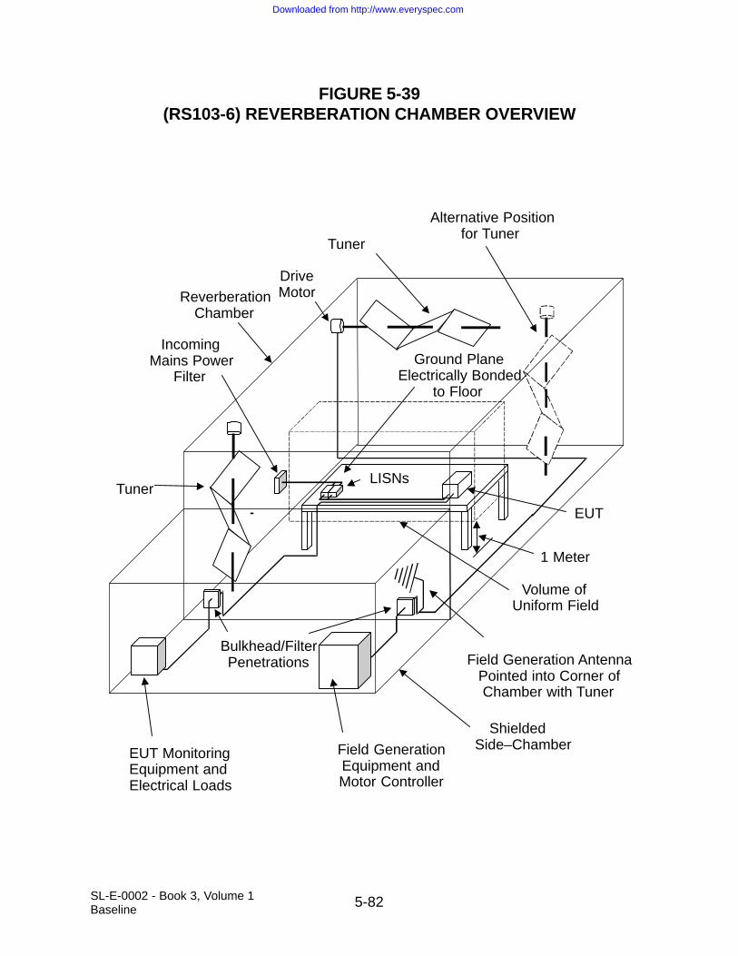
5-82SL-E-0002 - Book 3, Volume 1Baseline
FIGURE 5-39(RS103-6) REVERBERATION CHAMBER OVERVIEW
Tuner
Tuner
Alternative Positionfor Tuner
Ground PlaneElectrically Bonded
to Floor
IncomingMains Power
Filter
LISNs
EUT
EUT MonitoringEquipment andElectrical Loads
Field GenerationEquipment andMotor Controller
Field Generation AntennaPointed into Corner ofChamber with Tuner
ReverberationChamber
ShieldedSide–Chamber
Bulkhead/FilterPenetrations
DriveMotor
Volume ofUniform Field
1 Meter
Downloaded from http://www.everyspec.com

5-83SL-E-0002 - Book 3, Volume 1Baseline
5.14 TT101, CONDUCTED EMISSIONS, TIME DOMAIN, DC POWER LEADS, TRANSIENTAND STEADY-STATE
5.14.1 TT101 Applicability
The requirement is applicable for measurement of all turn-on and mode-switching transients.
5.14.2 TT101 Limits
Transient emissions on power leads shall not exceed the applicable values shown onFigure 5-40.
For electrical loads connected to Shuttle primary power without intermediate powerconversion, the steady-state ripple voltage in the time domain shall not exceed ±0.45volts line-to-line, starting approximately one second after the transient.
5.14.3 TT101 Test Procedure
5.14.3.1 Purpose
The purpose of this test method is to measure, in the time domain, the load inducedeffect on power bus voltage caused by cycling the EUT on, as well as through any andall of its various modes of operation which might reasonably be expected to affect linevoltage significantly, that is, in a manner approaching limits set forth in the governingpower quality specification.
5.14.3.2 Test Equipment
The test equipment shall be as follows:
a. LISN (8 µH/50 ohm, per Figure 5-40)
b. Data recording device
c. Solid-state switch (to energize/de-energize EUT)
d. Digital storage oscilloscope (10 MHz single event BW)
e. Resistive load for verifying test set-up and measurement accuracy
5.14.3.3 Setup
The test setup shall be as follows:
Downloaded from http://www.everyspec.com

5-84SL-E-0002 - Book 3, Volume 1Baseline
a. Maintain a basic test setup for the EUT as shown and described in Figure 4-1through Figure 4-5 and Paragraph 4.3.8.
b. Calibration.
Configure the test setup for the measurement system check as shown in Figure5-41. The resistor “Rload” in Figure 5-41 shall have a value that draws thesame steady-state current as the EUT.
c. EUT testing.
Configure the test setup for compliance testing of the EUT as shown in Figure 5-42.
5.14.3.4 Procedures
The test procedures shall be as follows:
a. Calibration. Perform the measurement system check using the measurementsystem check setup of Figure 5-41.
1. Turn on the measurement equipment and allow a sufficient time for stabilization.
2. For turn-on transient: Set time per division to bracket expected L/R timeconstant. Use 5 or 10 V/division sensitivity. Set up trigger to look for anegative-going transient. Set threshold to a few Volts below Voc. Set up asingle trace acquisition (acquire and hold).
3. Use oscilloscope to verify that transient waveforms are as shown in Figure 5-41.
b. EUT testing. Perform transient measurement using the setup of Figure 5-42.
1. Apply power to LISN. Wait at least one second after EUT has beende-energized before measuring a turn-on transient event.
2. Configure oscilloscope for turn-on transient measurement per Step a, Item 2 (above) except that transient waveform will typically be longer thanthat calibrated, and time per division will have to be empirically determined.
3. Measure and record turn-on transient as switch is closed. Configure oscil-loscope for steady-state measurement per Step a, Item 3 (above).
4. For steady-state measurement, set time per division to 1 microsecond.Use a vertical sensitivity of 100 mV/division, using either AC coupling or a
Downloaded from http://www.everyspec.com

5-85SL-E-0002 - Book 3, Volume 1Baseline
DC offset to keep trace at mid-screen. Repeat with a 100 microsecond perdivision time-base. Measure with a time per division setting commensuratewith time period associated with EUT current draw. Record steady-stateripple using a max or peak hold function. Record data for the greater ofone second or the longest cyclic period associated with EUT operation.
5.14.3.5 Data Presentation
Data presentation shall be as follows:
a. Oscillograph of transient waveform, including all axis and unit labels necessaryfor proper interpretation.
b. Display the applicable limit on each plot.
c. Provide plots for both the measurement system check and measurement por-tions of the procedure.
Downloaded from http://www.everyspec.com

5-86SL-E-0002 - Book 3, Volume 1Baseline
FIGURE 5-40
(TT101-1) TT101 POWER SOURCE IMPEDANCE AND TRANSIENTEXCURSION LIMIT
–40
–30
–20
–10
0
10
20
30
40
dB O
hm
10 k 0.1M 1M 10 M
Frequency Hz
25 Ohm
25 Ohm
25 mOhm
19,000 µF
powerinput
1 k100101
Note: 25 mOhm series resistance is anominal default. Actual value usedshould be the lesser of this value or thatvalue which multiplied by steady–stateEUT current draw yields a 0.1 Volt buspotential drop (± 20%) relative to theunloaded LISN output.
± 20% tolerance on LISN impedanceand dc voltage drop requirement
powerto EUT
25 mOhm
4 µH
4 µH
0
10
20
30
Bus
Pot
entia
l (V
olts
)
–25 0 25 50 75 100 125 150
Time before and after onset of transient (µs)
(90 µs, 20 V)
(45 µs, 10 V)
(90 - 150 µs, 27 V)
Note: LISN series resistanceis such that post transient buspotential returns to open circuitpotential less 0.1 Volt ± 20%.Return to nominal (open circuitpotential less 0.1 Volt ± 20%)to occur within 150 µs of onset.
(150 µs, 27.9 V)
Downloaded from http://www.everyspec.com

5-87SL-E-0002 - Book 3, Volume 1Baseline
FIGURE 5-41
(TT101-2) MEASUREMENT SYSTEM CHECK SETUP
∂t = 2L/R load
oscilloscope
Rload
Rs
Rs
L
LV
∂V = V oc •2R s /R loadVoc
0
turn – on transient
Downloaded from http://www.everyspec.com
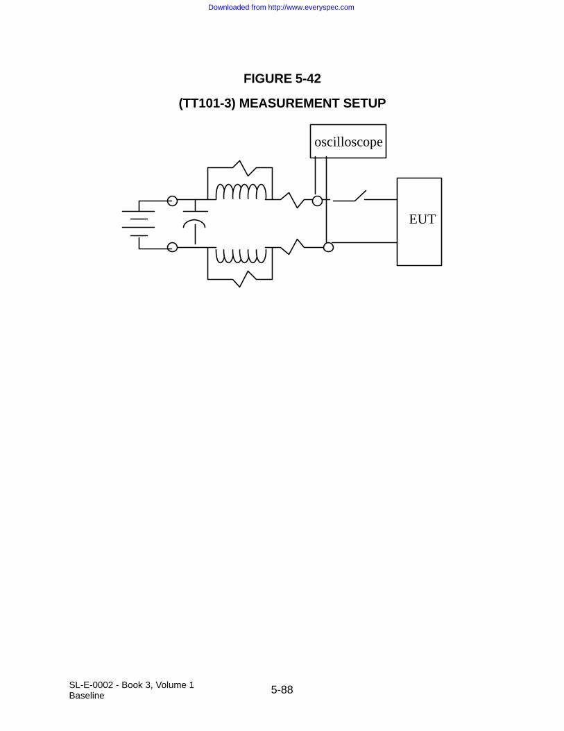
5-88SL-E-0002 - Book 3, Volume 1Baseline
FIGURE 5-42
(TT101-3) MEASUREMENT SETUP
EUT
oscilloscope
Downloaded from http://www.everyspec.com

6-1SL-E-0002 - Book 3, Volume 1Baseline
6.0 NOTES
This section contains information of a general or explanatory nature that may behelpful, but is not mandatory.
6.1 INTENDED USE
This standard is intended for use in the acquisition cycle of equipment and subsystemsto specify the electromagnetic emission and susceptibility requirements for the controlof EMI.
6.2 TAILORING GUIDANCE
Application specific criteria may be derived from operational and engineering analyseson the equipment or subsystem being procured for use in specific environments. Whenanalyses reveal that a requirement in this standard is not appropriate or adequate forthat procurement, the requirement should be tailored and incorporated into theappropriate documentation. The appendix of this standard provides guidance for tailoring.
Downloaded from http://www.everyspec.com

6-2SL-E-0002 - Book 3, Volume 1Baseline
THIS PAGE INTENTIONALLY LEFT BLANK
Downloaded from http://www.everyspec.com
SL-E-0002 - Book 3, Volume 1Baseline A-1
APPENDIX A
ACRONYMS AND ABBREVIATIONS
Downloaded from http://www.everyspec.com

SL-E-0002 - Book 3, Volume 1Baseline A-2
THIS PAGE INTENTIONALLY LEFT BLANK
Downloaded from http://www.everyspec.com

SL-E-0002 - Book 3, Volume 1Baseline A-3
APPENDIX A
ACRONYMS AND ABBREVIATIONS
AC Alternating CurrentAM Amplitude ModulationANSI American National Standards InstituteASTM American Society for Testing and MaterialsATP Authority to Proceed
BCE Bulk Current EmissionBW Bandwidth
CE Conducted EmissionCISPR International Special Committee on Radio Interferencecm centimeterCOTS Commercial Off-the-ShelfCS Conducted SusceptibilityCUT Cable-under-testCW Continuous Wave
dB decibeldBm decibel milliWattdBµV decibel microvoltsdBW decibel wattsDC Direct Currentdso digital oscilloscope
EMC Electromagnetic CompatibilityEMI Electromagnetic InterferenceEMICP EMI Control ProcedureEMITP EMI Test ProceduresEMITR EMI Test ReportEMP Electromagnetic PulseERP Effective Radiated PowerESD Electrostatic DischargeEUT Equipment Under Test
FCC Federal Communications CommissionFM Frequency Modulationfo frequencyo
Downloaded from http://www.everyspec.com

SL-E-0002 - Book 3, Volume 1Baseline A-4
GFE Government Furnished EquipmentGHz GigahertzGPI Ground Plane Interference
HF High FrequencyHz Hertz
IF Intermediate Frequency
kHz Kilohertz
LISN Line Impedance Stabilization Network
MHz Megahertz
NTIA National Telecommunications and Information Administration
pps pulse per secondprf pulse repetition frequency
Q quality factor
RC Resistor/CapacitorRE Radiated EmissionRF Radio FrequencyRMS Root Mean SquareRS Radiated Susceptibility
SAE Society of Automotive Engineerssec second(s)SI System InternationalSSV Space Shuttle Vehicle
TT Transient Test
UHF Ultrahigh Frequency
V VoltVDC Volts Direct Current
Downloaded from http://www.everyspec.com

SL-E-0002 - Book 3, Volume 1Baseline A-5
VHF Very High FrequencyVrms Volts root mean squareVSWR Voltage Standing Wave Ratio
SYMBOLSµH microHenry
Downloaded from http://www.everyspec.com

SL-E-0002 - Book 3, Volume 1Baseline A-6
THIS PAGE INTENTIONALLY LEFT BLANK
Downloaded from http://www.everyspec.com
SL-E-0002 - Book 3, Volume 1Baseline B-1
APPENDIX B
APPLICATION GUIDE
Downloaded from http://www.everyspec.com

SL-E-0002 - Book 3, Volume 1Baseline B-2
THIS PAGE INTENTIONALLY LEFT BLANK
Downloaded from http://www.everyspec.com
SL-E-0002 - Book 3, Volume 1Baseline B-3
APPENDIX B
APPLICATION GUIDE
1.1 SCOPE
This appendix provides background information for each EMI limit or test level andassociated test procedure contained in the main body of SL-E-0002 - Book 3. Thisinformation includes rationale for requirements, guidance in applying the requirements,and lessons learned from platform and laboratory experience. This information shouldhelp users understand the intent behind the requirements, should aid the procuringactivity in EMI requirements as necessary for particular applications, and should helpusers develop detailed test procedures based on the general test procedures in thisdocument. This appendix is provided for guidance purposes and, as such, should notbe interpreted as providing contractual requirements.
1.1.4 Structure
This appendix follows the same general format as the main body of the specification. A“Discussion” paragraph is provided for each requirement if deemed necessary. ForSection 5, discussion paragraphs on “Applicability and Limits” and “Test Procedures”are included.
4.1 APPLICATION OF SPECIFICATION
Discussion: The requirements in this section are universally applicable to all subsys-tems and equipment. Separate EMI requirements that are structured to addressspecific concerns with various classes of subsystems and equipment are contained inother portions of this specification.
This document is concerned only with specifying technical requirements for controllingEMI at the subsystem and equipment-level. The requirements in this document are notintended to be directly applied to subassemblies of equipment such as modules or cir-cuit cards. The basic concepts can be implemented at the subassembly level; however,significant tailoring needs to be accomplished for the particular application. Therequirements included herein are intended to be used as a baseline. Placement of MIL-STD-461E limits is based on demonstrated performance typically required for useon existing military platforms in order to achieve EMC. These have been tailored insome instances to better reflect SSV concerns. SSV system-level requirements dealingwith integration of subsystems and equipment are contained in SL-E-0001. SL-E-0001requirements include intra-system compatibility within the system, inter-system
Downloaded from http://www.everyspec.com

SL-E-0002 - Book 3, Volume 1Baseline B-4
compatibility with external RF environments, lightning protection, and hazards of elec-tromagnetic radiation to ordnance. The procuring activity and system contractorsshould review the requirements contained herein for possible tailoring based on systemdesign and expected operational environments. NTIA “Manual of Regulations and Pro-cedures for Federal Radio Frequency Management” provides requirements forcomplying with laws governing use of the RF spectrum by federal agencies.
Guidance and techniques which are helpful in meeting the requirements of this specifi-cation are contained in MIL-HDBK-241, Design Guide for Electromagnetic Interference(EMI) Reduction in Power Supplies, MIL-HDBK-253, Guidance for the Design and Testof Systems Protected Against the Effects of Electromagnetic Energy, MIL-HDBK-423,High-altitude Electromagnetic Pulse (HEMP) Protection for Fixed and TransportableGround Based C4 1 Facilities, AFSC DH 1-4, Electromagnetic Compatibility, and AMCPamphlet 706-410. MIL-HDBK-237, Guidance for Controlling Electromagnetic Envi-ronmental Effects on Platforms, Systems, and Equipment, provides guidance formanagement of EMC efforts. MIL-HDBK-235, Electromagnetic (Radiated) EnvironmentConsiderations for Design and Procurement of Electrical and Electronic Equipment,Subsystems and Systems, provides information on land, air, and sea based RF emit-ters, both hostile and friendly, which contribute to the overall electromagneticenvironment.
The qualification status of equipment and subsystems becomes uncertain when hard-ware or software changes are incorporated due to equipment updates or test failures,including failures from testing to requirements other than EMI. To maintain certificationto SL-E-0002 after changes are implemented, either an analysis showing no substan-tive impact needs to be issued or continued compliance needs to be demonstrated bylimited testing deemed to be appropriate to evaluate the changes. The approach usedto maintain continued certification and the results of analysis and testing are normallysubject to procuring activity approval.
4.1.3 COTS Equipment
Discussion: The use of COTS equipment presents a dilemma between the need forEMI control with appropriate design measures implemented and the desire to takeadvantage of existing designs which may exhibit undesirable EMI characteristics.
For some applications of commercially developed products, such as commercial trans-port aircraft, EMI requirements similar to those in this specification are usually imposedon equipment. Most commercial aircraft equipment is required to meet the EMI require-ments in RTCA DO-160, Environmental Conditions and Test Procedures for AirborneEquipment, or an equivalent contractor in-house document. Recent revisions to RTCADO-160 are making the document more compatible with this specification. Equipment
Downloaded from http://www.everyspec.com

SL-E-0002 - Book 3, Volume 1Baseline B-5
qualified to RTCA DO-160, Revisions C and D is often suitable for military aircraftapplications.
EMI requirements on most commercial equipment are more varied and sometimesnonexistent. The FCC is responsible for regulating non-licensed RF devices in thecommercial and residential environment to control interference to radio reception.Requirements are imposed in FCC CFR Title 47, Telecommunications, Part 2, Fre-quency Allocations and Radio Treaty Matters; General Rules and Regulations, Part 15,Radio Frequency Devices, and Part 18, Industrial, Scientific, and Medical Equipment.The FCC does not control susceptibility (referred to as immunity in the commercial com-munity) characteristics of equipment. The most widely applied requirement is Part 15which requires that any digital device comply with the following conducted and RE limitsfor commercial environments (Class A) and residential environments (Class B).
Conducted Emissions
Frequency(MHz)
Class A(dBµV)
Class B(dBµV)
0.45 - 1.705 60 48
1.705 - 30 70 48
Radiated Emissions
Frequency(MHz)
Class A(dBµV/m at 10 meters)
Class B(dBµV/m at 3 meters)
30 - 88 39 40
88 - 216 44 44
216 - 960 46 46
Above 960 50 54
These requirements are typically less stringent than military requirements of a similartype. Also, there is difficulty in comparing levels between commercial and militarytesting due to differences in measurement distances, different types of antennas, andnear-field conditions.
The commercial community is moving toward immunity standards. The basis for immu-nity requirements is given in ANSI C63.12, American National Standard RecommendedPractice for Electromagnetic Compatibility Limits. There is also activity in the interna-tional area. The European Union is imposing mandatory standards and theInternational Electrotechnical Commission is working on standards.
Downloaded from http://www.everyspec.com

SL-E-0002 - Book 3, Volume 1Baseline B-6
4.1.4.1 Certification to Another EMI Requirements Document
Discussion: In general, the government expects configuration controls to be exercisedin the manufacturing process of equipment and subsystems to ensure that produceditems continue to meet the particular EMI requirements to which the design was qualified. This specification reflects the most up-to-date environments and concerns.Since the original EMI requirements may be substantially different than those in thisspecification, they may not be adequate to assess the suitability of the item in a partic-ular installation. This situation most often occurs for equipment susceptibility testsrelated to the radiated electromagnetic environment. Procuring activities need to con-sider imposing additional test requirements on the contractor to gather additional datato permit adequate evaluation.
Testing of production items has shown degraded performance of the equipment fromthat previously demonstrated during development. One problem area is engineeringchanges implemented for ease of manufacturing which are not adequately reviewed forpotential effects on EMI control design measures. Specific problems have been relatedto treatment of cable and enclosure shields, electrical grounding and bonding, and sub-stitution of new component parts due to obsolescence.
4.1.6 Self-compatibility
Discussion: The EMI controls imposed by this specification apply to subsystem-levelhardware with the purpose of ensuring compatibility when various subsystems are inte-grated into a system platform. In a parallel sense, a subsystem can be considered tobe an integration of various assemblies, circuit cards, and electronics boxes. Whilespecific requirements could be imposed to control the interference characteristics ofthese individual items, this specification is concerned only with the overall performancecharacteristics of the subsystem after integration. Therefore, the subsystem itself mustexhibit compatibility among its various component parts and assemblies.
4.3 VERIFICATION REQUIREMENTS
Discussion: This portion of the document specifies general requirements that are appli-cable to a variety of test procedures applicable for individual EMI requirements. Thedetailed test procedures for each EMI requirement include procedures that are uniqueto that requirement. Other sources of information dealing with electromagnetic interfer-ence testing are available in industry documents such as RTCA DO-160 and SAE ARP1972, Recommended Measurement Practices and Procedures for EMC Testing.
Electromagnetic disciplines (EMC, EMP, lightning, RF compatibility, frequency alloca-tion, etc.) are integrated to differing levels in various government and contractororganizations. There is often a common base of requirements among the disciplines. It
Downloaded from http://www.everyspec.com

SL-E-0002 - Book 3, Volume 1Baseline B-7
is more efficient to have unified requirements and complete and concise testing. Forexample, the EMC, EMP and lightning areas all pertain to electronic hardness to tran-sients. The transient requirements in this specification should satisfy most concerns orshould be adapted as necessary to do so.
Testing integrated equipment at the subsystem-level is advantageous because theactual electrical interfaces are in place rather than electrical load or test equipment sim-ulations. When simulations are used, there is always doubt regarding the integrity ofthe simulation and questions arise whether emission and susceptibility problems aredue to the EUT or the simulation.
Contractor generated test procedures provide a mechanism to interpret and adaptSL-E-0002 as it is applicable to a particular subsystem or equipment and to detail thetest agency’s facilities and instrumentation and their use. It is important that the proce-dures are available to the procuring activity early so that the procuring activity canapprove the test procedures prior to the start of testing. Agreement needs to existbetween the procuring activity and the contractor on the interpretation of test require-ments and procedures, thereby minimizing the possible need for retesting.
When testing large equipment, equipment that requires special handling provision orhigh power equipment, deviations from the standard testing procedures may berequired. Large equipment may not fit through the typical shielded room door or maybe so heavy that it would crush the floor. Other equipment has large movable arms orturrets or equipment that requires special heating or cooling facilities. This equipmentmay have to be tested at the manufacturer’s facilities or at the final installation. The fol-lowing examples are for guidance. Sound engineering practices should be used andexplained in detail in the EMITP when deviating from the standard test procedures dueto EUT characteristics. The design of the tests is of primary importance and the datarecorded during the testing must reflect the final installation characteristics as closely aspossible.
For equipment which requires high input current (for example: > 200 A), commercialLISNs may not be available. For CE102, the voltage probe called out in ANSI C63.4,American National Standard for Methods of Measurement of Radio-Noise Emissionsfrom Low-Voltage Electrical and Electronic Equipment in the Range of 9 kHz to 40 GHz,may be substituted. The construction of the probe is shown in Figure B-1. A direct con-nection to the power lines is required and care must be taken to establish a referenceground for the measurements. It may be necessary to perform repeated measurementsover a suitable period of time to determine the variation in the power line impedanceand the impact on the measured emissions from the EUT. Alternatively, a current-based limit could be analytically derived in such a case and the test performed withcurrent probes, as per earlier version of this specification.
Downloaded from http://www.everyspec.com

SL-E-0002 - Book 3, Volume 1Baseline B-8
The measurements are made between each current-carrying conductor in the supplymains and the ground conductor with a blocking capacitor C and resistor R, as shown inFigure B-1, so that the total resistance between the line under test and ground is 1500ohm. The probe attenuates the voltage so calibration factors are required. The mea-surement point (probe’s position on the cables) must be identified in all test setups.
When equipment is too large or requires special provisions (loads, drives, water, emis-sion of toxic fumes and such), testing in a typical semi-anechoic room may not befeasible. Temporary screen rooms consisting of hardware cloth can be built around thetest area to reduce the ambient for RE testing and to contain the RF field during RStesting. Since the room may be highly reflective, care must be taken to identify any res-onances. Several antenna positions may be required in order to reduce the effect of theresonances, or stirring may be employed.
Equipment which produces high power RF output may be required to be tested on anopen area test site. Additionally, equipment that needs to have a communication link tothe outside world must be tested in the open. FCC approval may be required in orderto generate the RF fields for the RS103 test requirement. If the communication link canbe simulated, then the test can be performed in a shielded room. In this case, specialdummy loads may be required, since the high power RF radiation could damage theanechoic material due to heating.
Downloaded from http://www.everyspec.com

SL-E-0002 - Book 3, Volume 1Baseline B-9
FIGURE B-1
VOLTAGE PROBE FOR TESTS AT USER’S INSTALLATION
SUPPLY MAINS
C
XC < 1500 Ω
R = (1500 – RM ) Ω
XL > RM INPUT IMPEDANCE = R MΩ
MEASUREMENTRECEIVER
Imposition of EMI requirements on large equipment has become essential to preventEMI problems. Therefore, EMI requirements should not be waived simply because ofspecial handling problems or equipment size. Typical military equipment and subsys-tems for which these special provisions have been applied are as follows:
a. Air handling units (heating, ventilating, and air conditioning)
b. Large uninterruptible power supplies
c. Equipment vans/motorized vehicles
d. Desalinization units
e. Large motors/generators/drives/power distribution systems
f. Large radars
g. Rail guns and their power sources
h. Catapults and their power sources
i. Multiple console subsystems
Downloaded from http://www.everyspec.com

SL-E-0002 - Book 3, Volume 1Baseline B-10
An issue unique to space applications is that the EUT is often the flight unit. Specialcare must be exercised in these cases. Some types of test items are designed for lim-ited lifetimes, and/or are built to operate in microgravity or vacuum. Operation of suchequipment during a test program may affect useful lifetime. Special EMI test designsmay be required. One technique for reducing test time is to limit RE testing to receiverpassbands. All such measures should be described in detail in the EMI test plan, andpresented for approval by the designated approving authority well in advance of testing.
4.3.1 Measurement Tolerances
Discussion: Tolerances are necessary to maintain reasonable controls for obtainingconsistent measurements. Paragraph 4.3.1, Step b through Step d, are in agreementwith ANSI C 63.2 for electromagnetic noise instrumentation.
4.3.2 Shielded Enclosures
Discussion: Potential accuracy problems introduced by shielded enclosure resonancesare well documented and recognized; however, shielded enclosures are usually anecessity for testing of military equipment to the requirements of this specification.Most test agencies are at locations where ambient levels outside of the enclosures aresignificantly above the limits in this specification and would interfere with the ability toobtain meaningful data.
Electrical interfaces with military or space equipment are often complex and requiresophisticated test equipment to simulate and evaluate the interface. This equipmentusually must be located outside of the shielded enclosure to achieve sufficient isolationand prevent it from contaminating the ambient and responding to susceptibility signals.
The shielded enclosure also prevents radiation of applied susceptibility signals frominterfering with local antenna-connected receivers. The most obvious potential offenderis the RS103 test. However, other susceptibility tests can result in substantial radiatedenergy that may violate FCC rules.
4.3.2.1 RF Absorber Material
Discussion: Accuracy problems with making measurements in untreated shieldedenclosures due to reflections of electromagnetic energy have been widely recognizedand documented. The values of RF absorption required by Table B.1 are considered tobe sufficient to substantially improve the integrity of the measurements without undulyimpacting test facilities. The minimum placement provisions for the material are speci-fied to handle the predominant reflections. The use of additional material is desirable,where possible. It is intended that the values in Table B.1 can be met with available fer-rite tile material or standard 24 inch (0.61 meters) pyramidal absorber material.
Downloaded from http://www.everyspec.com

SL-E-0002 - Book 3, Volume 1Baseline B-11
TABLE B.1
ABSORPTION AT NORMAL INCIDENCE
Frequency Minimum Absorption
80 MHz - 250 MHz 6 dB
Above 250 MHz 10 dB
4.3.3 Other Test Sites
Discussion: For certain types of EUTs, testing in a shielded enclosure may not be prac-tical. Examples are EUTs, which are extremely large, require high electrical powerlevels or motor drives to function, emit toxic fumes, or are too heavy for normal floorloading (reference Paragraph 4.3, Discussion, for additional information). There is aserious concern with ambient levels contaminating data when testing is performed outside of a shielded enclosure. Therefore, special attention is given to this testingunder Paragraph 4.3.4. All cases, where testing is performed outside a shielded enclo-sure, should be justified in detail in the EMI test plan, including typical profiles ofexpected ambient levels.
If it is necessary to operate EUTs that include RF transmitters outside of a shieldedenclosure, spectrum certification and a frequency assignment must first be obtainedthrough the spectrum management process.
An option in emission testing is the use of an open area test site in accordance withANSI C63.4. These sites are specifically designed to enhance accuracy and repeat-ability. Due to differences between ANSI C63.4 and this specification in areas such asantenna selection, measurement distances, and specified frequency ranges, the EMITPshould detail the techniques for using the open area test site and relating the testresults to the requirements of this specification.
4.3.4 Ambient Electromagnetic Level
Discussion: Controlling ambient levels is critical to maintaining the integrity of the gath-ered data. High ambients present difficulties distinguishing between EUT emissionsand ambient levels. Even when specific signals are known to be ambient related, theymay mask EUT emissions that are above the limits of this specification.
The requirement that the ambient be at least 6 dB below the limit ensures that the com-bination of the EUT emissions and ambient does not unduly affect the indicatedmagnitude of the emission. If a sinusoidal noise signal is at the limit and the ambient is6 dB below the limit, the indicated level would be approximately 3 dB above the limit.
Downloaded from http://www.everyspec.com

SL-E-0002 - Book 3, Volume 1Baseline B-12
Similarly, if the ambient were allowed to be equal to the limit for the same true emissionlevel, the indicated level would be approximately 5 dB above the limit. Conversely, aflat noise floor level indicates that any signals present are at least 6 dB below the noisefloor, or the noise floor would be elevated. This is useful when very sensitive receiversdrive RE limits which are challenging to meet with off-the-shelf test equipment.
A resistive load is specified to be used for conducted ambients on power leads. How-ever, under certain conditions actual ambient levels may be higher than indicated with aresistive load. The most likely reason is the presence of capacitance at the power inter-face of the EUT that will lower the input impedance at higher frequencies and increasethe current. This capacitance should be determined and ambient measurementsrepeated with the capacitance in place. There is also the possibility of resonanceconditions with shielded room filtering, EUT filtering, and powerline inductance. Thesetypes of conditions may need to be investigated if unexpected emission levels areobserved.
Testing outside of a shielded enclosure often must be performed at night to minimizeinfluences of the ambient. A prevalent problem with the ambient is that it continuouslychanges with time as various emitters are turned on and off and as amplitudes fluc-tuate. A useful tool for improving the flow of testing is to thoroughly analyze the EUTcircuitry prior to testing and identify frequencies where emissions may be expected tobe present.
An option to improve overall measurement accuracy is to make preliminary measure-ments inside a shielded enclosure and accurately determine frequencies whereemissions are present. Testing can be continued outside the shielded enclosure withmeasurements being repeated at the selected frequencies. The 6 dB margin betweenthe ambient and limits must then be observed only at the selected frequencies.
4.3.5 Ground Plane
Discussion: Generally, the REs and RSs of equipment are due to coupling from and tothe interconnecting cables and not via the case of the EUT. Emissions and suscepti-bility levels are directly related to the placement of the cable with respect to the groundplane and to the electrical conductivity of the ground plane. Thus, the ground planeplays an important role in obtaining the most realistic test results.
When the EUT is too large to be installed on a conventional ground plane on a bench,the actual installation should be duplicated. For example, a large radar antenna mayneed to be installed on a test stand and the test stand bonded to the floor of theshielded enclosure. Ground planes need to be placed on the floor of shielded roomswith floor surfaces such as tiles that are not electrically conductive.
The use of ground planes is also applicable for testing outside of a shielded enclosure.These ground planes will need to be referenced to earth as necessary to meet the
Downloaded from http://www.everyspec.com

SL-E-0002 - Book 3, Volume 1Baseline B-13
electrical safety requirements of the National Electrical Code. Where possible, theseground planes should be electrically bonded to other accessible grounded referencesurfaces such as the outside structure of a shielded enclosure.
The minimum dimensions for a ground plane of 2.25 square meter with 76 cm on thesmallest side will be adequate only for setups involving a limited number of EUT enclo-sures with few electrical interfaces. The ground plane must be large enough to allowfor the requirements included in Paragraph 4.3.8 on positioning and arrangement of theEUT and associated cables to be met.
4.3.5.1 Metallic Ground Plane
Discussion: For the metallic ground plane, a copper ground plane with a thickness of0.25 millimeters has been commonly used and satisfies the surface resistancerequirements. Other metallic materials of the proper size and thickness needed toachieve the resistivity can be substituted.
For metallic ground planes, the surface resistance can be calculated by dividing thebulk resistivity by the thickness. For example, copper has a bulk resistivity of 1.75x10⁻⁸
ohm-meters. For a 0.25 millimeter thick ground plane as noted above, the surfaceresistance is 1.7x10⁻⁸/2.5x10-4 = 6.8x10⁻⁵ ohms per square = 0.068 milliohms persquare. The requirement is 0.1 milliohms per square.
4.3.5.2 Composite Ground Plane
Discussion: A copper ground plane has typically been used for all testing in the past.For most instances, this has been adequate. However, with the increasing use of com-posites, the appropriate ground plane will play a bigger role in the test results. Limitedtesting on both copper and conductive composite ground planes has shown some dif-ferences in electromagnetic coupling test results, thus the need exists to duplicate theactual installation, if possible. In some cases, it may be necessary to include severalground planes in the same test setup if different units of the same EUT are installed ondifferent materials in the installation.
With the numerous different composite materials being used in installations, it is notpossible to specify a general resistivity value. The typical resistivity of carbon com-posite is about 2,000 times that of aluminum. The actual resistivity needs to beobtained from the installation contractor and used for testing.
4.3.6 Power Source Impedance
Discussion: The impedance of the 50 µH, 50 Ω line-to-ground LISN is standardized torepresent expected impedances in actual installations and to ensure consistent results
Downloaded from http://www.everyspec.com

SL-E-0002 - Book 3, Volume 1Baseline B-14
between different test agencies. The impedance of the 8 µH, 50 ohm line-to-line LISN,is tailored specifically for SSV. Versions of MIL-STD-462 (previously contained test pro-cedures for MIL-STD-461, Requirements for the Control of Electromagnetic InterferenceCharacteristics of Subsystems and Equipment, requirements) in the past used 10microfarad feedthrough capacitors on the power leads. The intent of these devices wasto determine the current generator portion of a Norton current source model. If theimpedance of the interference source was also known, the interference potential of thesource could be analytically determined for particular circumstances in the installation.A requirement was never established for measuring the impedance portion of thesource model. More importantly, concerns arose over the test configuration influencingthe design of powerline filtering. Optimized filters are designed based on knowledge ofboth source and load impedances. Significantly different filter designs will result for the10 microfarad capacitor loading versus the impedance loading shown in Figure 4-7.
LISNs are not used on output power leads. Emission measurements using LISNs areperformed on input power leads because the EUT is using a power source common tomany other equipment items and the EUT must not degrade the quality of the power.When the EUT is the source of power, the issue is completely different since the elec-trical characteristics of the power required are controlled by the defined power qualityrequirements. Output power leads should be terminated with appropriate electricalloading that produces potentially worst case emission and susceptibility characteristics.
The particular configuration of the line-to-ground LISN is specified for several reasons.A number of experiments were performed to evaluate typical power line impedancespresent in a shielded room on various power input types both with and without powerline filters and to assess the possible methods of controlling the impedance. Anapproach was considered for MIL-STD-461E to simply specify an impedance curvefrom 30 Hz to 100 MHz and to allow the test agency to meet the impedance using what-ever means the agency found suitable. The experiments showed that there were nostraightforward techniques to maintain desired controls over the entire frequency range.
A specific 50 microhenry LISN (reference ANSI C63.4) was selected to maintain a stan-dardized control on the impedance as low as 10 kHz. Five microhenry LISNs usedcommonly in the past provide little control below 100 kHz. Impedance control below 10kHz is difficult. From evaluations of several 50 microhenry LISN configurations, the onespecified demonstrated the best overall performance for various shielded room filteringvariations. Near 10 kHz, the reactances of the 50 microhenry inductor and 8 microfaradcapacitor cancel and the LISN is effectively a 5 ohm resistive load across the powerline.
Using a common LISN is important for standardization reasons. However, the use ofalternative LISNs may be desirable in certain application where the characteristics ofthe LISN may not be representative of the actual installation and the design of EUT
Downloaded from http://www.everyspec.com

SL-E-0002 - Book 3, Volume 1Baseline B-15
circuitry is being adversely affected. For example, there are issues with switchingpower supply stability and the power source impedance seen by the power supply. The50 microhenry inductor in the LISN represents the inductance of power distributionwiring running for approximately 50 meters. For a large platform, such as a ship orcargo aircraft, this value is quite representative of the actual installation. However, forsmaller platforms such as fighter aircraft, inductance values may be substantially lowerthan 50 microhenries. If alternative LISN designs are used, certain issues need to beaddressed such as the frequency range over which effective impedance control ispresent and where voltage versus current measurements are appropriate.
Caution needs to be exercised in using the LISN for 400 Hz power systems. Someexisting LISNs may not have components sufficient to handle the power dissipationrequirements. At 115 volts, 400 Hz, the 8 microfarad capacitor and 5 ohm resistor willpass approximately 2.3 amperes which results in 26.5 watts being dissipated in theresistor.
The SSV-specific LISN is used to measure time-domain phenomena. Measured eventsare transient deviations from nominal conditions. Limits are levied as to the length ofthe transient event. Therefore, the LISN must be defined to have a DC resistance aswell as an AC impedance, in order to accurately measure the transient return to nom-inal conditions. This results in the requirement for series impedance in the LISN. Thevalue used, and how to tailor it for different EUT load currents, is discussed in theappendix for the TT101 test section.
4.3.7 General Test Precautions
Discussion: The requirements included in Paragraph 4.3.7 cover important areasrelated to improving test integrity and safety that need special attention. There aremany other areas where test difficulties may develop. Some are described here.
It is common for shields to become loose or broken at connectors on coaxial cablesresulting in incorrect readings. There also are cases where center conductors ofcoaxial cables break or separate. Periodic tests should be performed to ensure cableintegrity. Special low loss cables may be required when testing at higher frequencies.
Caution needs to be exercised when performing emission testing at frequencies belowapproximately 10 kHz to avoid ground loops in the instrumentation which may introducefaulty readings. A single-point ground often needs to be maintained. It is usually nec-essary to use isolation transformers at the measurement receiver and accessoryequipment. The single-point ground is normally established at the access (feedthrough)panel for the shielded enclosure. However, if a transducer is being used which requiresan electrical bond to the enclosure (such as the rod antenna counterpoise), the coaxialcable will need to be routed through the enclosure access panel without being
Downloaded from http://www.everyspec.com

SL-E-0002 - Book 3, Volume 1Baseline B-16
grounded. Since the shielded room integrity will then be compromised, a normal mul-tiple point grounded setup needs to be re-established as low in frequency as possible.
Rather than routing the coaxial cable through the enclosure access panel withoutgrounding it to the enclosure, a 50-ohm video isolation transformer may be connectedto the grounded RF connector at the access panel inside the room. Normal connectionof the measuring receiver is made to the grounded connector at the panel outside theroom. This technique effectively breaks the ground loop without sacrificing the room’sshielding integrity. The losses of the video isolation transformer must be accounted forin the measurement data. These devices are typically useful up to approximately 10MHz.
If isolation transformers are found to be necessary in certain setups, problems mayexist with items powered by switching power supplies. A solution is to use transformersthat are rated at approximately five times the current rating of the item.
Solid state instrumentation power sources have been found to be susceptible toradiated fields even to the extent of being shut down. It is best to keep these items out-side of the shielded enclosure.
4.3.7.1 Accessory Equipment
Discussion: Measurement receivers are generally designed to meet the limits of thisspecification so they do not contaminate the ambient for emission testing when they areused inside the shielded enclosure. However, accessory equipment such as com-puters, oscilloscopes, plotters, or other instruments used to control the receiver ormonitor its outputs can cause problems. They may compromise the integrity of thereceiver by radiating signals conducted out of the receiver from improperly treated elec-trical interfaces or may produce interference themselves and raise the ambient. Evenpassive devices such as headsets have been known to impact the test results.
It is best to locate all of the test equipment outside of the shielded enclosure with theobvious exception of the transducer (antenna or current probe). Proper equipmentlocation will ensure that the emissions being measured are being generated in the EUTonly and will help ensure that the ambient requirements of Paragraph 4.3.4 are met. Ifthe equipment must be used inside the enclosure or if testing is being conducted out-side of an enclosure, the measurement receiver and accessory equipment should belocated as far away from the transducers as practical to minimize any impact.
4.3.7.2 Excess Personnel and Equipment
Discussion: Excess personnel and both electronic and mechanical equipment suchas desks or cable racks in the enclosure can affect the test results. During radiated
Downloaded from http://www.everyspec.com

SL-E-0002 - Book 3, Volume 1Baseline B-17
emission testing in particular, all nonessential personnel and equipment need to beremoved from the test site. Any object in the enclosure can significantly influence orintroduce standing waves in the enclosure and thus alter the test results. The require-ment to use RF absorber material will help to mitigate these effects. However, materialperformance is not defined below 80 MHz for practical reasons and standing wavescontinue to be a concern.
4.3.7.3 Overload Precautions
Discussion: Overloads can easily go unnoticed if there is not an awareness of the pos-sibility of an overload or active monitoring for the condition. The usual result is aleveling of the output indication of the receiver.
Two types of overloads are possible. A narrowband signal, such as a sinusoid, can sat-urate any receiver or active transducer. Typical procedures for selecting attenuationsettings for measurement receivers place detected voltages corresponding to emissionlimits well within the dynamic range of the receiver. Saturation problems for narrow-band type signals will normally only appear for a properly configured receiver ifemissions are significantly above the limits. Saturation can occur more readily whenreceivers are used to monitor susceptibility signals due to the larger voltages involved.
Overload from impulsive type signals with broad frequency content can be much moredeceptive. This condition is most likely to occur with devices without a tuneable band-pass feature in the first stage of the signal input. Examples are preamplified rodantennas and spectrum analyzers without preselectors. The input circuitry is exposedto energy over a large portion of the frequency spectrum. Preselectors include a tune-able tracking filter which BW limits the energy applied to the receiver front end circuitry.
Measurement receiver overload to both narrowband and impulsive type signals can beevaluated by applying 10 dB additional attenuation in the first stage of the receiver(before mixer circuitry) or external to the receiver. If overload is not present, theobserved output will uniformly decrease by 10 dB.
Overload conditions for active antennas are normally published as part of the literaturesupplied with the antenna. For narrowband signals, the indicated level in the data canbe reviewed with respect to the literature to evaluate overload. Levels are also pub-lished for impulsive type signals; however, these levels are not very useful since theyusually assume that a flat field exists across the useable range of the antenna. Inreality, the impulsive field will vary significantly with frequency and the antenna circuitrysees the integration of the spectral content of this field over its bandpass. The primaryactive antenna used is an active rod antenna. Overload can be evaluated by collapsingthe rod and observing the change in indication. If overload is not present, the indicatedlevel should drop approximately 8 dB (rod at 30% of its original height). The actual
Downloaded from http://www.everyspec.com

SL-E-0002 - Book 3, Volume 1Baseline B-18
change for any particular manufacturer’s product will depend on the telescoping designand can be determined by radiating a signal to the antenna that is within its linearrange.
4.3.7.4 RF Hazards
Discussion: During some RS and RE testing, fields may exceed the permissible expo-sure levels in DoDI 6055011, Protection of DoD Personnel from Exposure toRadiofrequency Radiation and Military Exempt Lasers. During these tests, precautionsmust be implemented to avoid inadvertent exposure of personnel. Monitoring of theEUT during testing may require special techniques such as remotely connected dis-plays external to the enclosure or closed circuit television to adequately protectpersonnel.
4.3.7.5 Shock Hazard
Discussion: A safety plan and training of test personnel are normally required to assurethat accidents are minimized. Test equipment manufacturers’ precautions need to befollowed, if specified. If these are not available, the test laboratory should establishadequate safety precautions and train all test personnel.
4.3.7.6 FCC Restrictions
Discussion: RS RS103 testing and possibly other tests will produce signals above FCCauthorizations. This situation is one of the reasons that shielded enclosures are nor-mally required.
4.3.8 EUT Test Configurations
Discussion: Emphasis is placed on maintaining the specified setup for all testing unlessa particular test procedure directs otherwise. Confusion has resulted from previous ver-sions of the standard regarding consistency of setups between individual requirementsin areas such as lead lengths and placement of 10 uF capacitors on power leads. Inthis version of the specification, any changes from the general test setup are specificallystated in the individual test procedure.
4.3.8.1 EUT Design Status
Discussion: It is important that the hardware and software being tested is the same asthe production equipment. Sometimes equipment is tested which is pre-production andcontains circuit boards that do not include the final layout or software that is not the finalversion. Questions inevitably arise concerning the effects of the differences between
Downloaded from http://www.everyspec.com

SL-E-0002 - Book 3, Volume 1Baseline B-19
the tested equipment and production configurations on the qualification status of theequipment. Analytically determining the impact is usually very difficult.
4.3.8.2 Bonding of EUT
Discussion: Electrical bonding provisions for equipment are an important aspect of plat-form installation design. Adequacy of bonding is usually one of the first areas reviewedwhen platform problems develop. Electrical bonding controls common mode voltagesthat develop between the equipment enclosures and the ground plane. Voltages poten-tially affecting the equipment will appear across the bonding interface when RF stressesare applied during susceptibility testing. Voltages will also develop due to internal circuitoperation and will contribute to RE profiles. Therefore, it is important that the test setupuse actual bonding provisions so that test results are representative of the intendedinstallation.
4.3.8.3 Shock and Vibration Isolators
Discussion: Including shock and vibration isolators in the setup when they representthe platform installation is important. The discussion above for Paragraph 4.3.8.2 isalso applicable to shock and vibration isolators; however, the potential effect on testresults is even greater. Hard mounting of the equipment enclosures to the groundplane can produce a low impedance path across the bonding interface over most of thefrequency range of interest. The bonding straps associated with isolators will typicallyrepresent significant impedances at frequencies as low as tens of kHz. The commonmode voltages associated with these impedances will generally be greater than thehard mounted situation. Therefore, the influence on test results can be substantial.
4.3.8.4 Safety Grounds
Discussion: Safety grounds used in equipment enclosures have been the source ofproblems during EMI testing. Since they are connected to the equipment enclosure,they would be expected to be at a very low potential with respect to the ground planeand a non-contributor to test results. However, the wire lengths within enclosures areoften sufficiently long that coupling to them results from noisy circuits. Also, safetygrounds can conduct induced signals from external sources and reradiate within theequipment enclosure. Therefore, they must be treated similarly to other wiring.
4.3.8.5 Orientation of EUTs
Discussion: Determination of appropriate surfaces is usually straightforward. Seamson enclosures that have metal-to-metal contact or contain EMI gaskets rarely contributeand should be considered low priority items. Prime candidates are displays such as
Downloaded from http://www.everyspec.com

SL-E-0002 - Book 3, Volume 1Baseline B-20
video screens, ventilation openings, and cable penetrations. In some cases, it may benecessary to probe the surfaces with a sensor and measurement receiver to decide onEUT orientation.
MIL-STD-462, superseded by this specification, specifically required probing with a loopantenna to determine localized areas producing maximum emissions or susceptibilityfor radiated electric field testing. The test antennas were to be placed one meter fromthe identified areas. The requirement was not included in this specification due to diffi-culties in applying the requirement and the result that probing was often not performed.Probing implies both scanning in frequency and physical movement of the probe.These two actions cannot be performed in a manner to cover all physical locations at allfrequencies. A complete frequency scan can be performed at particular probe locationsand movement of the probe over the entire test setup can be performed at particularfrequencies. The detailed requirements on the use of multiple antenna positions andspecific requirements on the placement of the antennas in test procedures for RE102and RS103 minimize concerns with the need to probe.
4.3.8.6 Construction and Arrangement of EUT Cables
Discussion: For most EUTs, electrical interface requirements are covered in interfacecontrol or similar documents. Coordination between equipment manufacturers andsystem integration organizations is necessary to ensure a compatible installation fromboth functional and EMI standpoints. For general purpose EUTs, which may be used inmany different installations, either the equipment specifications cover the interfacerequirements or the manufacturers publish recommendations in the documentationassociated with the equipment.
Equipment manufacturers sometimes contend that failures during EMI testing are notdue to their equipment and can be cured simply by placing overall shields on the inter-face cabling. High level emissions are often caused by electronic circuits within EUTenclosures coupling onto cables simulating the installation which interface with the EUT.Overall shielding of the cabling is certainly permissible if it is present in the installation.However, the use of overall shielding that is not representative of the installation wouldresult in test data that is useless. Also, overall shielding of cabling in some installationsis not a feasible option due to weight and maintenance penalties. The presence of plat-form structure between cabling and antennas on a platform is not an acceptable reasonfor using overall shields on cables for testing in accordance with this specification. Thepresence of some platform shielding is a basic assumption.
An issue that arises with power leads concerns the use of shielding. It is unusual forpower leads to be shielded in the actual installation. If they come directly off a primepower bus, shielding can only be effective if the entire bus is shielded end-to-end.Since buses normally distribute power to many locations, it is not practical to shield
Downloaded from http://www.everyspec.com

SL-E-0002 - Book 3, Volume 1Baseline B-21
them. An exception to this situation is when power is derived from an intermediatesource that contains filtering. Shielding between the intermediate source and the EUTwill then be effective. When it is proposed that shielded power leads be used in the testsetup, the configuration needs to be researched to ensure that it is correct. There maybe instances when published interface information is not available. In this case, overallshielding is not to be used. Individual circuits are to be treated as they typically wouldfor that type of interface with shielding not used in questionable cases.
For some testing performed in the past using bulk cable drive techniques, overall cableshields were routinely removed and the injected signal was applied to the core wiringwithin the shield. The intent of this specification is to test cables as they are configuredin the installation. If the cable uses an overall shield, the test signal is applied to theoverall shielded cable. If the procuring agency desires that the test be performed onthe core wiring, specific wording needs to be included in contractual documentation.
4.3.8.6.1 Interconnecting Leads and Cables
Discussion: Actual lengths of cables used in installations are necessary for several rea-sons. At frequencies below resonance, coupling is generally proportional to cablelength. Resonance conditions will be representative of the actual installation. Also, dis-tortion and attenuation of intentional signals due strictly to cable characteristics will bepresent and potential susceptibility of interface circuits to induced signals will thereforebe similar to the actual installation.
Zig-zagging of long cables is accomplished by first placing a length of cable in an openarea and then reversing the direction of the cable run by 180 degrees each time achange of direction is required. Each subsequent segment is farther from the first.Individual segments of the cable are parallel and should be kept 2 cm apart. The zig-zagging of long cables rather than coiling is to control excess inductance. A 2 cmspacing between cables is required to expose all cabling to the test antennas and limitcoupling of signals between cables. The 10 cm dimension for cables along the frontedge of the ground plane ensures that there is both sufficient ground plane surfacebelow the first cable to be effective, and that the cables are near enough the edge tosimulate radiation as when they are installed along the front edge of an equipment rack.The 5 cm standoffs standardize loop areas available for coupling and capacitance to theground plane. The standoffs represent routing and clamping of cables in actual installa-tions a fixed distance from structure.
The requirement that the first two meters of each interconnecting cable associated witheach enclosure of the EUT be routed parallel to the front boundary of the setup isintended to ensure that REs and susceptibility testing properly assesses the perfor-mance of the EUT. Noise signals developed within the EUT and conducted outside onelectrical interfaces will tend to be attenuated as they travel along interconnecting
Downloaded from http://www.everyspec.com

SL-E-0002 - Book 3, Volume 1Baseline B-22
cables, particularly at frequencies where the associated wavelength is becoming shortcompared with the cable length. Similarly, induced signals on interconnecting cablesfrom RS fields will be attenuated as they travel along the cable. Requiring that the firsttwo meters of the cabling be exposed therefore maximizes the effects of potentialradiated coupling. When extension cables must be built, it is advantageous if the con-nection can be made at the bulkhead feedthrough point between test and controlchambers. Especially if the individual signals are shielded, and/or there is an over-shield, a bulkhead feedthrough connector is extremely effective in limiting noisepollution from support equipment in control chamber from polluting the test chamberambient.
In some military applications, there can be over 2,000 cables associated with a sub-system. In most cases where large numbers of cables are involved, there will be manyidentical cable interfaces connected to identical circuitry. Testing of every cable inter-face is not necessary in this situation. The EMITP should document instances wherethese circumstances exist and should propose which cables are to be included in thesetup and to be tested.
4.3.8.6.2 Input Power Leads
Discussion: Appropriate power lead length is a trade-off between ensuring sufficientlength for efficient coupling of radiated signals and maintaining the impedance of theLISNs. To keep a constant setup, it is undesirable to change the power lead length fordifferent test procedures. Requiring a 2 meter exposed length is consistent with treat-ment of interconnecting leads for radiated concerns. Wiring inductance 5 cm from aground plane is approximately 1 H/meter. At 1 MHz this inductance has an impedanceof approximately 13 ohms which is significant with respect to the LISN requirement.
While it is common to require that neutrals and returns be isolated from equipmentchassis within equipment enclosures, there are some cases where the neutral or returnis tied directly to chassis. If the equipment is electrically bonded to metallic systemstructure in the installation and the system power source neutral or return is also tied tosystem structure, power return currents will flow primarily through system structurerather than through wiring. For this case, a LISN should normally be used only on thehigh side of the power. There are other installations, such as many types of aircraft,where returns and neutrals are isolated within the equipment, but they are often con-nected to system structure outside of the equipment enclosure. This practice allows forthe flexibility of using a wired return, if necessary. For this situation, LISNs should nor-mally be used on neutrals and returns to test for the wired return configuration.
The LISN requirement standardizes impedance for power leads. While signal and con-trol circuits are usually terminated in specified impedances, power circuit impedancesare not usually well defined. The LISN requirement applies to all input prime power
Downloaded from http://www.everyspec.com

SL-E-0002 - Book 3, Volume 1Baseline B-23
leads. The LISN requirement does not apply to output power leads. These leadsshould be terminated after the two meter exposed length in a load representing worst-case conditions. This load would normally draw the maximum current allowed for thepower source.
The construction of the power cable between the EUT and the LISNs must be in accor-dance with the requirements of Paragraph 4.3.8.6. For example, if a twisted triplet isused to distribute three-phase ungrounded power in the actual installation, the sameconstruction should be used in the test setup. The normal construction must be inter-rupted over a sufficient length to permit connection to the LISNs.
4.3.8.7 Electrical and Mechanical Interfaces
Discussion: The application of signals to exercise the electrical interface is necessaryto effectively evaluate performance. Most electronic subsystems on platforms arehighly integrated with large amounts of digital and analog data being transferredbetween equipment. The use of actual platform equipment for the interfacing eliminatesconcerns regarding proper simulation of the interface. The interfaces must functionproperly in the presence of induced levels from susceptibility signals. Required isolationmay be obtained by filtering the interface leads at the active load and either shieldingthe load or placing it outside of the shielded enclosure. The filtering should be selectedto minimize the influence on the interface electrical properties specified above. Forproper simulation, filtering at the loads should be outside the necessary BW of the inter-face circuitry.
Antenna ports are terminated in loads for general setup conditions. Specific testprocedures address electromagnetic characteristics of antenna ports and requiredmodifications to the test setup.
4.3.9 Operation of EUT
Discussion: The particular modes selected may vary for different test procedures. Con-siderations for maximum emissions include conditions which cause the EUT to drawmaximum prime power current, result in greatest activity in interface circuit operation,and generate the largest current drain on internal digital clock signals. Settings for aradar could be adjusted such that an output waveform results which has the highestavailable average power. Data bus interfaces could be queried frequently to causeconstant bus traffic flow. Any modes of the EUT that are considered mission critical inthe installation should be evaluated during susceptibility testing.
A primary consideration for maximum susceptibility is placing the EUT in its most sensi-tive state for reception of intentional signals (maximum gain). An imaging sensor wouldnormally be evaluated with a scene meeting the most stringent specifications for the
Downloaded from http://www.everyspec.com
SL-E-0002 - Book 3, Volume 1Baseline B-24
sensor. RF receivers are normally evaluated using an input signal at the minimumsignal to noise specification of the receiver. However, mission profiles must be kept inmind. If a particular threat transmission originated from the same source as a signal tobe received, then it is unlikely that the signal would be received near the receiver’snoise floor when the threat is at 200 V/m. Judgment must be used, and rationale sup-plied in the EMITP. An additional consideration is ensuring that all electrical interfacesthat intentionally receive data are exercised frequently to monitor for potentialresponses.
4.3.9.1 Operating Frequencies for Tunable RF Equipment
Discussion: Tuned circuits and frequency synthesis circuitry inside RF equipment typi-cally vary in characteristics such as response, rejection, and spectral content ofemissions as they are set to different frequencies. Several test frequencies arerequired simply to obtain a sampling of the performance of the EUT across its operatingrange.
RF equipment that operates in several frequency bands or performs multiple functionsis becoming more common. One example is a radio transceiver with Very High Fre-quency (VHF)-Frequency Modulation (FM), VHF-Amplitude Modulation (AM), andUltrahigh Frequency (UHF)-AM capability. Other devices are adaptive over large fre-quency ranges and can be programmed to perform different functions as the needarises. To meet the intent of the requirement to perform measurements at three fre-quencies within each tuning band, tuning unit, or range of fixed channels, each of thethree functions of the radio in the example should be treated as separate bands, even ifthey are adjacent in frequency. Similarly, each function of adaptive RF equipmentneeds to be separately assessed.
The “value added” of performing all required tests at three frequencies within each bandneeds to be weighed against the added cost and schedule. The specific equipmentdesign and intended function needs to be evaluated for each case.
For example, performing CS101 on a VHF-FM, VHF-AM, and UHF-AM combinedreceiver-transmitter would require that the test be performed a minimum of 18 times(3 frequencies • 3 bands • 2 modes). Since CS101 performance generally is related tothe power supply design and load rather than the specific tuned frequency, doing thetest for more than a few conditions may not add much value. If there is a problem, atypical result is “hum” on the secondary power outputs that is transmitted with the RFor that appears on the output audio of the receiver portion of the equipment. Anappropriate approach for this particular requirement might be to test at one mid-bandfrequency for each of the three functions for both transmit and receive (6 tests - 3 frequencies • 2 modes).
Downloaded from http://www.everyspec.com

SL-E-0002 - Book 3, Volume 1Baseline B-25
Other requirements need to be evaluated similarly. Since CE102 emissions are mainlycaused by power supply characteristics, testing at a mid-band frequency for each bandjust in the transmit mode might be adequate. For requirements with frequency cov-erage that extends into the operating frequency range of the equipment, such asRE102, CE106, and RS103, testing at three frequencies per band may be necessary.
4.3.9.2 Operating Frequencies for Spread Spectrum Equipment
Discussion: During testing it is necessary to operate equipment at levels that they willexperience during normal field operations to allow for a realistic representation of theemission profile of the EUT during radiated and conducted testing and to provide real-istic loading and simulation of the EUT during radiated and CS testing.
Frequency hopping - Utilization of a hopset that is distributed across the entire opera-tional spectrum of the EUT will help assure that internal circuitry dependent on theexact EUT transmit frequency being used is active intermittently during processing ofthe entire pseudo random stream. The fast operating times of hopping receivers/trans-mitters versus the allowable measurement times of the measurement receivers beingused (reference Paragraph 4.3.10.3) will allow a representative EUT emission signatureto be captured.
Direct sequence - Requiring the utilization of the highest data transfer rate used inactual operation of the EUT should provide a representative worst-case radiated andCE profile. Internal circuitry will operate at its highest processing rate when integratingthe data entering the transmitter, and then resolving (disintegrating) the data back onceagain on the receiver end. Additionally, the data rate will need to be an area of con-centration during all susceptibility testing.
4.3.9.3 Susceptibility Monitoring
Discussion: Most EUTs can be adequately monitored through normal visual and auraloutputs, self diagnostics, and electrical interfaces. The addition of special circuitry formonitoring can present questions related to its influence on the validity of the testresults and may serve as an entry or exit point for electromagnetic energy.
The monitoring procedure needs to be specified in the EMITP and needs to includeallowances for possible weaknesses in the monitoring process to assure the highestprobability of finding regions of susceptibility. Monitoring techniques should allow forrealtime susceptibility evaluation, and should facilitate easy discovery of degradation.Inspecting data at the end of a susceptibility test or at the end of a frequency bandsweep to determine pass/fail criteria can lead to very long tests if failures are found.One workaround is to accurately time stamp both frequency sweeps and EUT dataoutput so that faults and frequencies can be time-correlated. Asking a human operator
Downloaded from http://www.everyspec.com

SL-E-0002 - Book 3, Volume 1Baseline B-26
to examine large blocks of hexadecimal data words looking for errors is not as likely tofind faults as a program which compares data to expected values and provides analarm for an error condition.
4.3.10 Use of Measurement Equipment
Discussion: Questions frequently arise concerning the acceptability for use of measure-ment receivers other than instruments that are specifically designated “field intensitymeters” or “EMI receivers.” Most questions are directed toward the use of spectrumanalyzers. These instruments are generally acceptable for use. However, dependingon the type, they can present difficulties that are not usually encountered with the otherreceivers. Sensitivity may not be adequate in some frequency bands requiring that alow noise preamplifier be inserted before the analyzer input. Impulse type signals fromthe EUT with broad spectral content may overload the basic receiver or preamplifier.The precautions of Paragraph 4.3.7.3 must be observed. Both of these concerns canusually be adequately addressed by the use of a preselector with the analyzer. Thesedevices typically consist of a tunable filter which tracks the analyzer followed by apreamplifier.
ANSI C63.2 represents a coordinated position from industry on required characteristicsof instrumentation receivers. This document can be consulted when assessing the per-formance of a particular receiver.
Many of the test procedures require non-specialized instrumentation that is used formany other purposes. The test facility is responsible for selecting instrumentation thathas characteristics capable of satisfying the requirements of a particular test procedure.
Current probes used for EMI testing are more specialized instrumentation. Thesedevices are current transformers with the circuit under test forming a single turn primary.They are designed to be terminated in 50 ohms. Current probes are calibrated usingtransfer impedance that is the ratio of the voltage output of the probe across 50 ohms tothe current through the probe. Probes with higher transfer impedance provide bettersensitivity. However, these probes also result in more series impedance added to thecircuit with a greater potential to affect the electrical current level. The series imped-ance added by the probe is the transfer impedance divided by the number of turns inthe secondary winding on the probe. Typical transfer impedances are 5 ohms or less.Typical added series impedance is 1 ohm or less.
4.3.10.1 Detector
Discussion: The function of the peak detector and the meaning of the output indicationon the measurement receiver are often confusing. Although there may appear to be aninherent discrepancy in the use of the terms “peak” and “RMS” together, there is no
Downloaded from http://www.everyspec.com

SL-E-0002 - Book 3, Volume 1Baseline B-27
contradiction. All detector functions (that is peak, carrier, field intensity, and quasi-peak)process the envelope of the signal present in the receiver Intermediate Frequency (IF)section. All outputs are calibrated in terms of an equivalent RMS value. For a sinewave input to the receiver, the signal envelope in the IF section is a DC level and alldetectors produce the same indicated RMS output. Calibration in terms of RMS is nec-essary for consistency. Signal sources are calibrated in terms of RMS. If a 0 dBm (107dBµV) unmodulated signal is applied to the receiver, the receiver must indicate 0 dBm(107 dBµV).
If there is modulation present on the signal applied to the receiver, the detectorsrespond differently. The IF section of the receiver sees the portion of the applied signalwithin the BW limits of the IF. The peak detector senses the largest level of the signalenvelope in the IF and displays an output equal to the RMS value of a sine wave withthe same peak. The specification of a peak detector ensures that the worst case condi-tion for emission data is obtained. A carrier detector averages the modulation envelopebased on selected charge and discharge time constants.
Figure B-2 shows the peak detector output for several modulation waveforms. An itemof interest is that for a square wave modulated signal, which can be considered a pulsetype modulation, the receiver can be considered to be displaying the RMS value of thepulse when it is on. Pulsed signals are often specified in terms of peak power. TheRMS value of a signal is derived from the concept of power, and a receiver using apeak detector correctly displays the peak power.
Downloaded from http://www.everyspec.com

SL-E-0002 - Book 3, Volume 1Baseline B-28
FIGURE B-2
PEAK DETECTOR RESPONSE
IF SIGNAL EQUIVALENT SINE WAVE, SAME PEAK
A A
B B
C C
RECEIVER OUTPUT INDICATION WILL BE , RESPECTIVELY
All frequency domain measurements are standardized with respect to the response thata measurement receiver using a peak detector would provide. Therefore, when instru-mentation is used which does not use peak detection, correction factors must beapplied for certain signals. For an oscilloscope, the maximum amplitude of the modu-lated sine wave measured from the level is divided by 1.414 (square root of 2) todetermine the RMS value at the peak of the modulation envelope.
Correction factors for other devices are determined by evaluating the response of theinstrumentation to signals with the same peak level with and without modulation. Forexample, a correction factor for a broadband field sensor can be determined as follows.Place the sensor in an unmodulated field and note the reading. Apply the requiredmodulation to the field ensuring that the peak value of the field is the same as theunmodulated field. For pulse type modulation, most signal sources will output the samepeak value when modulation is applied. Amplitude modulation increases the peakamplitude of the signal and caution must be observed. Note the new reading. Thecorrection factor is simply the reading with the unmodulated field divided by the reading
Downloaded from http://www.everyspec.com

SL-E-0002 - Book 3, Volume 1Baseline B-29
with the modulated field. If the meter read 10 volts/meter without modulation and 5volts/meter with modulation, the correction factor is 2. The evaluation should be tried atseveral frequencies and levels to ensure that a consistent value is obtained. Whensubsequently using the sensor for measurements with the evaluated modulation, theindicated reading is multiplied by the correction factor to obtain the correct reading forpeak detection.
4.3.10.2 Computer-controlled Receivers
Discussion: Computer software obviously provides excellent opportunities for auto-mating testing. However, it also can lead to errors in testing if not properly used or ifincorrect code is present. It is essential that users of the software understand the func-tions it is executing, know how to modify parameters (such as transducer or sweepvariables) as necessary, and perform sanity checks to ensure that the overall systemperforms as expected.
4.3.10.3 Emission Testing
4.3.10.3.1 Bandwidths
Discussion: The BWs specified in Table 4.3 are defaults consistent with the recom-mended available BWs and the BW specification technique for receivers contained inANSI C63.2. If an SSV receiver has a BW significantly different than those listed inTable 4.3, consideration to tailoring the measurement bandwidth in that band should beconsidered. Existing receivers have BWs specified in a number of different ways.Some are given in terms of 3 dB down points. The 6 dB BWs are usually about 40%greater than the 3 dB values. Impulse BWs are usually very similar to the 6 dB BWs.For gaussian shaped bandpasses, the actual value is 6.8 dB.
The frequency break point between using a 1 kHz and 10 kHz BW was modified from250 kHz to 150 kHz in this version of the specification to harmonize with commercialEMI standards.
In order not to restrict the use of presently available receivers that do not have the spe-cified BWs, larger BWs are permitted. The use of larger BWs can produce higherdetected levels for wide BW signals. The prohibition against the use of correction fac-tors is included to avoid any attempts to classify signals. MIL-STD-461D, Requirementsfor the Control of Electromagnetic Interference Characteristics of Subsystems andEquipment, eliminated the concept of classification of emissions as broadband ornarrowband in favor of fixed BWs and single limits. Emission classification was a con-troversial area often poorly understood and handled inconsistently among differentfacilities.
Downloaded from http://www.everyspec.com
SL-E-0002 - Book 3, Volume 1Baseline B-30
The sensitivity of a particular receiver is an important factor in its suitability for use inmaking measurements for a particular requirement. RE102 is usually the mostdemanding requirement. The sensitivity of a receiver at room temperature can be calculated as follows:
Sensitivity in dBm = -114 dBm/MHz + BW (dBMHz) + noise figure (dB)
As noted in the equation, reducing the noise figure is the only way (cryogenic cooling isnot practical) to improve sensitivity for a specified BW. The noise figure of receiverscan vary substantially depending on the front end design. System noise figure can beimproved through the use of low noise preamplifiers. The resulting noise figure of apreamplifier/receiver combination can be calculated from the following. All numbers arereal numbers. Conversion to dB (10 log) is necessary to determine the resulting sensi-tivity in the formula, which is an approximation valid in those cases when receiver noisefigure or gain are large with respect to one:
System noise figure = preamp noise figure + (receiver noise figure)/(preamp gain)
Since preamplifiers are broadband devices, issues of potential overload need to beaddressed. Separate preselectors, which are available for some spectrum analyzers,usually combine a tracking filter with a low noise preamplifier to eliminate overload.Preselection is an integral part of many receivers.
4.3.10.3.2 Emission Identification
Discussion: Requirements for specific BWs and the use of single limits are intended toresolve a number of problems. Versions of MIL-STD-461 and MIL-STD-462 prior to the“D” revision and of SL-E-0002 prior to the “F” revision had no controls on required BWsand provided both narrowband and broadband limits over much of the frequency rangefor most emission requirements. The significance of the particular BWs chosen for useby a test facility were addressed by classification of the appearance of the emissionswith respect to the chosen BWs. Emissions considered to be broadband had to benormalized to equivalent levels in a 1 MHz BW. The BWs and classification techniquesused by various facilities were very inconsistent and resulted in a lack of standardiza-tion. The basic issue of emission classification was often poorly understood andimplemented. Requiring specific bandwidths with a single limit eliminates any need toclassify emissions.
An additional problem is that emission profiles from modern electronics are often quitecomplex. Some emission signatures have frequency ranges where the emissionsexhibit white noise characteristics. Normalization to a 1 MHz BW using spectral ampli-tude assumptions based on impulse noise characteristics is not technically correct.Requiring specific BWs eliminates normalization and this discrepancy.
Downloaded from http://www.everyspec.com

SL-E-0002 - Book 3, Volume 1Baseline B-31
4.3.10.3.3 Frequency Scanning
Discussion: For each emission test, the entire frequency range as specified for theapplicable requirement must be scanned to ensure that all emissions are measured.
Continuous frequency coverage is required for emission testing. Testing at discrete fre-quencies is not acceptable unless otherwise stated in a particular test procedure. Theminimum scan times listed in Table 4.3 are based on two considerations. The first con-sideration is the response time of a particular BW to an applied signal. This time is1/(filter BW). The second consideration is the potential rates (that is modulation,cycling, and processing) at which electronics operate and the need to detect the worstcase emission amplitude. Emission profiles usually vary with time. Some signals arepresent only at certain intervals and others vary in amplitude. For example, signalscommonly present in emission profiles are harmonics of microprocessor clocks. Theseharmonics are very stable in frequency; however, their amplitude tends to change asvarious circuitry is exercised and current distribution changes.
The first entry in the table for analog measurement receivers of 0.015 sec/Hz for a BWof 10 Hz is the only one limited by the response time of the measurement receiverbandpass. The response time is 1/BW = 1/10 Hz = 0.1 seconds. Therefore, as thereceiver tunes, the receiver bandpass must include any particular frequency for 0.1 sec-onds implying that the minimum scan time = 0.1 seconds/10 Hz = 0.01 seconds/Hz.The value in the table has been increased to 0.015 seconds/Hz to ensure adequatetime. This increase by a multiplication factor of 1.5 results in the analog receiver havinga frequency in its bandpass for 0.15 seconds as it scans. This value is the dwell timespecified in the table for synthesized receivers for 10 Hz BWs. Since synthesizedreceivers are required to step in one-half BW increments or less and dwell for 0.15seconds, test time for synthesized receivers will be greater than analog receivers.
The measurement times for other table entries are controlled by the requirement thatthe receiver bandpass include any specific frequency for a minimum of 15 milliseconds(dwell time in table), which is associated with a potential rate of variation of approxi-mately 60 Hz. As the receiver tunes, the receiver bandpass is required to include anyparticular frequency for the 15 milliseconds. For the fourth entry in the table of 1.5seconds/MHz for a 10 kHz BW, the minimum measurement time is 0.015 seconds/0.01MHz = 1.5 seconds/MHz. A calculation based on the response time of the receiverwould yield a response time of 1/BW = 1/10 kHz = 0.0001 seconds and a minimummeasurement time of 0.0001 seconds/0.01 MHz = 0.01 seconds/MHz. The longermeasurement time of 1.5 seconds/MHz is specified in the table. If the specified mea-surement times are not adequate to capture the maximum amplitude of the EUTemissions, longer measurement times should be implemented.
Caution must be observed in applying the measurement times. The specifiedparameters are not directly available on measurement receiver controls and must be
Downloaded from http://www.everyspec.com

SL-E-0002 - Book 3, Volume 1Baseline B-32
interpreted for each particular receiver. Also, the specified measurement times may betoo fast for some data gathering devices such as realtime X-Y recording. Measurementreceiver peak hold times must be sufficiently long for the mechanical pen drive on X-Yrecorders to reach the detected peak value. In addition, the scan speed must be suffi-ciently slow to allow the detector to discharge after the signal is detuned so that thefrequency resolution requirements of Paragraph 4.3.10.3.4 are satisfied.
For measurement receivers with a “maximum hold” feature that retains maximumdetected levels after multiple scans over a particular frequency range, multiple fastersweeps that produce the same minimum test times as implied by Table 4.3 are accept-able. For the situation noted in the requirement concerning equipment that producesemissions at only infrequent intervals, using the multiple scan technique will usually pro-vide a higher probability of capturing intermittent data than using one slower scan.
Tailoring to shorten these sweep times is reasonable for equipment whose emissionprofile is time invariant. This is especially useful when the EUT must be exercised forshort time periods only. Any such tailoring should be described and justified in theEMITP.
4.3.10.3.4 Emission Data Presentation
Discussion: Versions of MIL-STD-462 prior to the “D” revision permitted data to betaken at the three frequencies per octave for the highest amplitude emissions. Thisapproach is no longer acceptable. Continuous displays of amplitude versus frequencyare required. This information can be generated in a number of ways. The data can beplotted realtime as the receiver scans. The data can be stored in computer memoryand later dumped to a plotter. Photographs of video displays are acceptable; however,it is generally more difficult to meet resolution requirements and to reproduce data inthis form for submittal in an EMITR.
Placement of limits can be done in several ways. Data may be displayed with respectto actual limit dimensions (such as dBµV/m) with transducer, attenuation, and cable losscorrections made to the data. An alternative is to plot the raw data in dBµv (or dBm)and convert the limit to equivalent dBµv (or dBm) dimensions using the correction fac-tors. This second technique has the advantage of displaying the proper use of thecorrection factors. Since both the emission level and the required limit are known, asecond party can verify proper placement. Since the actual level of the raw data is notavailable for the first case, this verification is not possible.
An example of adequate frequency and amplitude resolution is shown in Figure B-3.One percent frequency resolution means that two sinusoidal signals of the sameamplitude separated by 1% of the tuned frequency are resolved in the output display sothat they both can be seen. As shown in the figure, 1% of the measurement frequency
Downloaded from http://www.everyspec.com
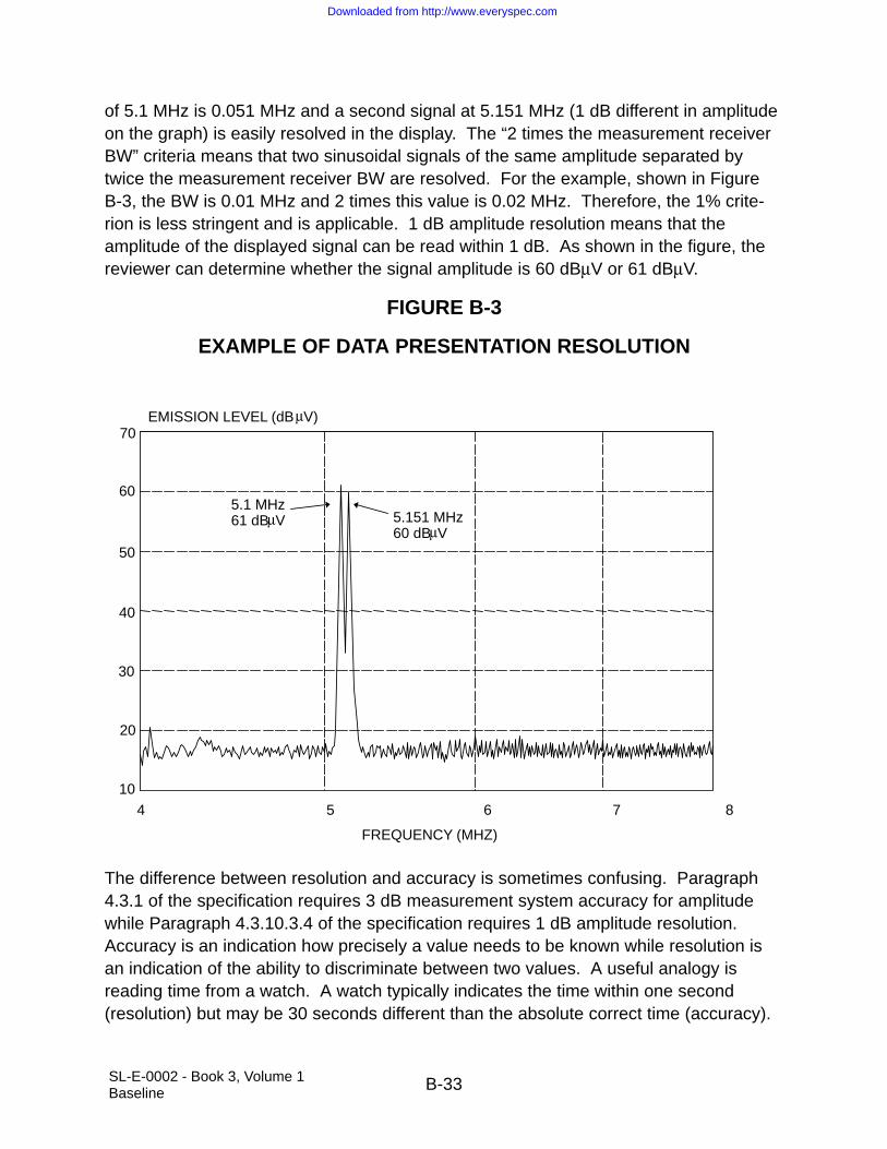
SL-E-0002 - Book 3, Volume 1Baseline B-33
of 5.1 MHz is 0.051 MHz and a second signal at 5.151 MHz (1 dB different in amplitudeon the graph) is easily resolved in the display. The “2 times the measurement receiverBW” criteria means that two sinusoidal signals of the same amplitude separated bytwice the measurement receiver BW are resolved. For the example, shown in FigureB-3, the BW is 0.01 MHz and 2 times this value is 0.02 MHz. Therefore, the 1% crite-rion is less stringent and is applicable. 1 dB amplitude resolution means that theamplitude of the displayed signal can be read within 1 dB. As shown in the figure, thereviewer can determine whether the signal amplitude is 60 dBµV or 61 dBµV.
FIGURE B-3
EXAMPLE OF DATA PRESENTATION RESOLUTION
4 5 6 7 8
FREQUENCY (MHZ)
10
20
30
40
50
60
70
5.1 MHz61 dBµV 5.151 MHz
60 dBµV
EMISSION LEVEL (dBµV)
The difference between resolution and accuracy is sometimes confusing. Paragraph4.3.1 of the specification requires 3 dB measurement system accuracy for amplitudewhile Paragraph 4.3.10.3.4 of the specification requires 1 dB amplitude resolution.Accuracy is an indication how precisely a value needs to be known while resolution isan indication of the ability to discriminate between two values. A useful analogy isreading time from a watch. A watch typically indicates the time within one second(resolution) but may be 30 seconds different than the absolute correct time (accuracy).
Downloaded from http://www.everyspec.com

SL-E-0002 - Book 3, Volume 1Baseline B-34
4.3.10.4 Susceptibility Testing
4.3.10.4.1 Frequency Scanning
Discussion: For any susceptibility test performed in the frequency domain, the entirefrequency range as specified in the applicable requirement must be scanned to ensurethat all potentially susceptible frequencies are evaluated.
The scan rates and step sizes in Table 4.4 are structured to allow for a continuouschange in value with frequency for flexibility. Computerized test systems could be pro-grammed to change values very frequently. A more likely application is to block offselected bands for scanning and to base selections of scan rate or step size on thelowest frequency. For example, if 1 - 2 GHz were selected, the maximum scan ratewould be (0.000667 X 1 GHz)/sec which equals 0.667 MHz/sec and the maximum stepsize would be 0.001 X 1 GHz which equals 1 MHz. Both automatic and manual scan-ning are permitted.
The two primary areas of concern for frequency scanning for susceptibility testing areresponse times for EUTs to react to stimuli and how sharply the responses tune withfrequency, normally expressed as quality factor (Q). Both of these items have beenconsidered in the determination of the scan rates and step sizes in Table 4.4. The tableentries are generally based on the assumption of a maximum EUT response time ofthree seconds and Q values of 10, 50, 100, 500, and 1000 (increasing values as fre-quency increases in Table 4.4). Since EUT responses are more likely to occur inapproximately the 1 to 200 MHz range due to efficient cable coupling based on wave-length considerations, Q values have been increased somewhat to slow the scan andallow additional time for observation of EUT responses. More detailed discussions onthese items follow.
The assumption of a maximum response time of three seconds is considered to beappropriate for a large percentage of possible cases. There are several considerations.While the electronics processing the interfering signal may respond quickly, the outputdisplay may take some time to react. Outputs that require mechanical motion such asmeter movements or servo driven devices will generally take longer to show degrada-tion effects than electronic displays such as video screens. Another concern is thatsome EUTs will only be in particularly susceptible states periodically. For example, sen-sors feeding information to a microprocessor are typically sampled at specific timeintervals. It is important that the susceptibility stimuli be located at any critical frequen-cies when the sensor is sampled. The time intervals between steps and sweep rates inTable 4.4 may need to be modified for EUTs with unusually long response times.
Some concern has been expressed on the susceptibility scan rates and the impact thatthey would have on the length of time required to conduct a susceptibility test. The
Downloaded from http://www.everyspec.com

SL-E-0002 - Book 3, Volume 1Baseline B-35
criteria of Table 4.4 allow the susceptibility scan rate to be adjusted continually as thefrequency is increased; however, as a practical matter, the rate would most likely onlybe changed once every octave or decade. As an example, Table B.2 splits the fre-quency spectrum up into ranges varying from octaves to decades and lists the minimumtime required to conduct a susceptibility test for an analog scan. The scan rate for eachrange is calculated based on the start frequency for the range. The total test time to runRS103 from 1 MHz to 18 GHz is 177 minutes. A similar calculation for a stepped scanresults in a total test time which is 2 times this value or 353 minutes. It must be empha-sized that the scan speeds should be slowed down if the EUT response time or Q aremore critical than those used to establish the values in Table 4.4.
Q is expressed as fo/BW where fo is the tuned frequency and BW is the width in fre-quency of the response at the 3 dB down points. For example, if a response occurredat 1 MHz at a susceptibility level of 1 volt and the same response required 1.414 volts(3 dB higher in required drive) at 0.95 and 1.05 MHz, the Q would be 1 MHz/(1.05 -0.95 MHz) or 10. Q is primarily influenced by resonances in filters, interconnectingcabling, physical structure, and cavities. The assumed Q values are based on observa-tions from various types of testing. The step sizes in Table 4.4 are one half of the 3 dBBWs of the assumed value of Q ensuring that test frequencies will lie within the reso-nant responses.
Below approximately 200 MHz, the predominant contributors are cable and interfacefilter resonances. There is loading associated with these resonances which dampensthe responses and limits most values of Q to less than 50. Above 200 MHz, structuralresonances of enclosures and housings start playing a role and have higher values of Qdue to less dampening. Above approximately 1 GHz, aperture coupling with excitationof cavities will be become dominant. Values of Q are dependent on frequency and onthe amount of material contained in the cavity. Larger values of Q result when there isless material in the volume. A densely packaged electronics enclosure will exhibit sig-nificantly lower values of Q than an enclosure with a higher percentage of emptyvolume. Q is proportional to volume/(surface area X skin depth). The value of Q alsotends to increase with frequency as the associated wavelength becomes smaller. EUTdesigns with unusual configurations that result in high Q characteristics may requirethat the scan rates and step sizes in Table 4.4 be decreased for valid testing.
Downloaded from http://www.everyspec.com

SL-E-0002 - Book 3, Volume 1Baseline B-36
TABLE B.2
SUSCEPTIBILITY TESTING TIMES
Frequency Range Maximum Scan Rate Actual Scan Time
30 Hz - 100 Hz 1.0 Hz/sec 1.2 min
100 Hz - 1 kHz 3.33 Hz/sec 4.5 min
1 kHz - 10 kHz 33.3 Hz/sec 4.5 min
10 kHz - 100 kHz 333 Hz/sec 4.5 min
100 kHz - 1 MHz 33.3 kHz/sec 4.5 min
1 MHz - 5 MHz 6.67 kHz/sec 10 min
5 MHz - 30 MHz 33.3 kHz/sec 12.5 min
30 MHz - 100 MHz 100 kHz/sec 11.7 min
100 MHz - 200 MHz 333 kHz/sec 5.0 min
200 MHz - 400 MHz 667 kHz/sec 5.0 min
400 MHz - 1 GHz 1.33 MHz/sec 7.5 min
1 GHz - 2 GHz 0.667 MHz/sec 25.0 min
2 GHz - 4 GHz 1.33 MHz/sec 25.0 min
4 GHz - 8 GHz 2.67 MHz/sec 25.0 min
8 GHz - 12 GHz 2.67 MHz/sec 25.0 min
12 GHz - 18 GHz 4 MHz/sec 25.0 min
18 GHz - 30 GHz 6 MHz/sec 33.3 min
30 GHz - 40 GHz 10 MHz/sec 16.7 min
RF processing equipment presents a special case requiring unique treatment. Inten-tionally tuned circuits for processing RF can have very high values of Q. For example,a circuit operating at 1 GHz with a BW of 100 kHz has a Q of 1 GHz/100 kHz or 10,000.
Automatic leveling used to stabilize the amplitude of a test signal for stepped scans mayrequire longer dwell times than one second at discrete frequencies. The signal will taketime to settle and any EUT responses during the leveling process should be ignored.
For SSV, susceptibility tests other than CS103, 104, and 105 may use 1% frequencysteps throughout, except at frequencies approaching passbands of receivers or othersharply tuned circuits.
Downloaded from http://www.everyspec.com

SL-E-0002 - Book 3, Volume 1Baseline B-37
4.3.10.4.2 Modulation of Susceptibility Signals
Discussion: CS114 and RS103 specify pulse modulation at a 1 kHz rate, 50% dutycycle, (alternately termed 1 kHz square wave modulation) for several reasons. OnekHz is within the bandpass of most analog circuits such as audio or video. The fast riseand fall times of the pulse causes the signal to have significant harmonic content high infrequency and can be detrimental to digital circuits. Response of electronics has beenassociated with energy present and a square wave results in high average power. Themodulation encompasses many signal modulations encountered in actual use. Thesquare wave is a severe form of amplitude modulation used in communications andbroadcasting. It also is a high duty cycle form of pulse modulation representative ofradars.
RS103 also specifies a low duty cycle pulse modulation in the microwave bands forEMC critical equipments which are subjected to a 200 V/m peak field intensity above 1GHz. Equipments which are deemed flight or safety critical (flight and engine controls)typically have small BWs and hence are likely to respond to average rather than peakpower. Imposing the square wave modulation in bands where the threats are mainlylow duty-cycle radars is deemed overly restrictive.
Modulation is usually the effect that degrades EUT performance. The wavelengths ofthe RF signal cause efficient coupling to electrical cables and through apertures (athigher frequencies). Non-linearities in the circuit elements detect the modulation on thecarrier. The circuits may then respond to the modulation depending upon detectedlevels, circuit bandpass characteristics, and processing features.
Care needs to be taken in implementing 1 kHz, 50% duty cycle, pulse modulation(on/off ratio of 40 dB) using some signal sources. Most higher frequency signal sourceshave either internal pulse modulation or an external port for pulse modulation. Thisfunction switches the output on and off without affecting the amplitude of the unmodu-lated signal, provided that the strength of the modulation signal is adequate. For othersignal sources, particularly at lower frequencies, the external AM port needs to bedriven to a minimum of 99% depth of modulation (equivalent to 40 dB on/off ratio) tosimulate pulse modulation. The output signal will essentially double in amplitudecompared to an unmodulated signal for this type of input. Depending on the type oftesting being performed and the technique of monitoring applied signals, this effect mayor may not influence the results. Use of an AM port can be substantially more involvedthan using a pulse modulation port. The amplitude of the input signal directly influencesthe depth of modulation. There is a potential of exceeding 100% depth of modulation,which will result in signal distortion. Since the on/off ratio requirement is stringent, it isnecessary to view the output signal on an oscilloscope to set the appropriate depth ofmodulation. Another complication is that the BW of AM ports is usually less than pulse
Downloaded from http://www.everyspec.com

SL-E-0002 - Book 3, Volume 1Baseline B-38
ports. Driving the port with a pulse shape may result in difficulty in setting the source fora minimum of 99%.
MIL-STD-461A, Requirements for the Control of Electromagnetic Interference Charac-teristics of Subsystems and Equipment, required that the worst case modulation for theEUT be used. Worst case modulation usually was not known or determined. Also,worst case modulation may not be related to modulations seen in actual use or may bevery specialized. The most typical modulations used below approximately 400 MHzhave been amplitude modulation at either 400 or 1000 Hz (30 to 80%) or pulse modula-tion, 50% duty cycle, at 400 or 1000 Hz. These same modulations have been usedabove 400 MHz together with pulse modulation at various pulse widths and pulse repe-tition frequencies. Continuous Wave ([CW] - no modulation) has also occasionally beenused. CW typically produces a detected DC level in the circuitry and affects certaintypes of circuits. In general, experience has shown that modulation is more likely tocause degradation. CW should be included as an additional requirement whenassessing circuits that respond only to heat such as electroexplosive devices. CWshould not normally be used as the only condition.
Consideration should be given to applying a secondary 1 Hz modulation (where thenormal 1 kHz square wave modulated waveform is completely turned on and off every500 milliseconds) for certain subsystems with low frequency response characteristics,such as aircraft flight control subsystems. This modulation simulates characteristics ofsome transmitters such as High Frequency (HF) radios in single sideband operation (nocarrier), where a transmitted voice signal will cause the RF to be present only when aword is spoken. The dilemma with using this modulation is that the potential responseof some subsystems may be enhanced, while others may be less responsive. In thelatter case, the 500 millisecond “off” period allows the subsystem to recover from effectsintroduced during the “on” period.
For SSV purposes, if a particularly severe threat source has a known modulation char-acteristic, that modulation may be substituted for the default modulation. This isparticularly useful if the modulation is FM, phase-shifted Tracking and Data Relay Satel-lite System, or very narrow low duty cycle pulses (radar). The typical EUT is lesssusceptible to these types of modulation than to the default 1 kHz waveform.
4.3.10.4.3 Thresholds of Susceptibility
Discussion: It is usually necessary to test at levels above the limits to ensure that thetest signal is at least at the required level. Determination of a threshold of susceptibilityis necessary when degradation is present to assess whether requirements are met.This information should be included in the EMITR. Threshold levels below limits areunacceptable.
Downloaded from http://www.everyspec.com

SL-E-0002 - Book 3, Volume 1Baseline B-39
The specified steps to determine thresholds of susceptibility standardize a particulartechnique. An alternative procedure sometimes utilized in the past was to use the valueof the applied signal where the EUT recovers (reference Section 4, Paragraph4.3.10.4.3, Thresholds of Susceptibility, Step a, in the general requirements section)as the threshold. Hysteresis type effects are often present where different values areobtained for the two procedures.
Distortion of sinusoidal susceptibility signals caused by non-linear effects in poweramplifiers can lead to erroneous interpretation of results. When distortion is present,the EUT may actually respond to a harmonic of the intended susceptibility frequency,where the required limit may be lower. When frequency selective receivers are used tomonitor the injected level, distortion itself does not prevent a valid susceptibility signallevel from being verified at the intended frequency. However, harmonic levels should bechecked when susceptibility is present to determine if they are influencing the results.When broadband sensors are being used, such as in portions of RS103, distortion canresult in the sensor incorrectly displaying the required signal level at the intended fre-quency. In this case, distortion needs to be controlled such that correct levels aremeasured.
4.3.11 Calibration of Measuring Equipment
Discussion: Calibration is typically required for any measurement device whose charac-teristics are not verified through use of another calibrated item during testing. Forexample, it is not possible during testing to determine whether an antenna used to mea-sure REs is exhibiting correct gain characteristics. Therefore, these antennas requireperiodic calibration. Conversely, a power amplifier used during RS testing often will notrequire calibration since application of the proper signal level is verified through the useof a separate calibrated field sensing device. Other amplifier applications such as theuse of a signal pre-amplifier in front of a measurement receiver would require calibra-tion of the amplifier characteristics since the specific gain versus frequency response iscritical and is not separately verified.
4.3.11.1 Measurement System Test
Discussion: The end-to-end system check prior to emission testing is valuable in dem-onstrating that the overall measurement system is working properly. It evaluates manyfactors including proper implementation of transducer factors and cable attenuation,general condition and setting of the measurement receiver, damaged RF cables orattenuators, and proper operation of software. Details on implementation are includedin the individual test procedures.
Downloaded from http://www.everyspec.com

SL-E-0002 - Book 3, Volume 1Baseline B-40
4.3.11.2 Antenna Factors
Discussion: SAE ARP-958 provides a standard basis for determining antenna factorsemission testing. A caution needs to be observed in trying to apply these factors inapplications other than EMI testing. The two antenna technique for antennas such asthe biconical and double ridge horns is based on far field assumptions which are notmet over much of the frequency range. Although the factors produce standardizedresults, the true value of the electric field is not necessarily being provided through theuse of the factor. Different measuring sensors need to be used when the true electricfield must be known.
5.1 GENERAL
Discussion: The applicability of individual requirements in Table 5.1 for a particularequipment or subsystem is dependent upon the platforms where the item will be used.The electromagnetic environments present on a platform together with potential degra-dation modes of electronic equipment items play a major role regarding whichrequirements are critical to an application. For example, emissions requirements aretied to protecting antenna-connected receivers on platforms. The operating frequencyranges and sensitivities of the particular receivers on-board a platform, therefore, influ-ence the need for certain requirements.
The EMI control plan, EMITPs, and EMITR are important elements in documentingdesign efforts for meeting the requirements of this specification, testing approacheswhich interpret the generalized test procedures in this specification, and reporting of theresults of testing. The EMI control plan is a mechanism instituted to help ensure thatcontractors analyze equipment design for EMI implications and include necessary mea-sures in the design for compliance with requirements. Approval of the document doesnot indicate that the procuring activity agrees that all the necessary effort is stated in thedocument. It is simply a recognition that the design effort is addressing the correctissues.
The susceptibility limits are the upper bound on the range of values for which com-pliance is required. The EUT must also provide required performance at any stresslevel below the limit. For example, if the limit for RS to electric fields is 20 volts/meter,the EUT must also meet its performance requirements at 10 volts/meter or any otherfield less than or equal to 20 volts/meter. There have been cases documented whereequipment (such as equipment with automatic gain control circuitry) was not susceptibleto radiated electric fields at given frequencies at the limit level but was susceptible tothe environment at the same frequencies when exposed to fields below the limit level.
5.1.1 Units of Frequency Domain Measurements
Discussion: A detailed discussion is provided on peak envelope detection in Paragraph4.3.10.1. A summary of output of the detector for several input waveforms is as follows.
Downloaded from http://www.everyspec.com
SL-E-0002 - Book 3, Volume 1Baseline B-41
For an unmodulated sine wave, the output simply corresponds to the RMS value of thesine wave. For a modulated sine wave, the output is the RMS value of an unmodulatedsine wave with the same absolute peak value. For a signal with a BW greater than theBW of the measurement receiver, the output is the RMS value of an unmodulated sinewave with the same absolute peak value as the waveform developed in the receiverbandpass.
5.2 CE102, CONDUCTED EMISSIONS, POWER LEADS, 10 kHz TO 10 MHz
Applicability and Limits: The requirements are applicable to leads that obtain powerfrom sources that are not part of the EUT. There is no requirement on output leadsfrom power sources.
The basic concept in the lower frequency portion of the requirement is to ensure thatthe EUT does not corrupt the power quality (allowable voltage distortion) on the powerbuses present on the platform. Examples of power quality documents are MIL-STD-704, Aircraft Electric Power Characteristics, for aircraft, MIL-STD-1399, InterfaceStandard for Shipboard Systems, for ships, MIL-STD-1539, Electrical Power, DirectCurrent, Space Vehicle Design Requirements, for space systems, and MIL-STD-1275,Characteristics of 28 Volt DC Electrical Systems in Military Vehicles, for militaryvehicles. Electrical power quality for the Space Shuttle is described in MF-0004-02,Electrical Design Requirements for Electrical Equipment Utilized on the Space ShuttleVehicle. The military standards described above differ in one important respect fromShuttle power quality. The source of Shuttle DC power is a fuel cell, which, loaded in atime independent manner produces pure DC power with no inherent ripple. Thereforelimiting load-induced effects is the only control necessary or exerted to control steady-state power bus ripple. While the CE102 28 VDC limit is not specifically tailored forShuttle use, it is considered to be sufficient to adequately control load-induced ripple.The CE102 curve for 115 VAC power is also sufficient for control of load-induced rippleon the 400 Hz bus as well. Unlike aircraft, where 28 VDC is either transformed and rec-tified 400 Hz power, or directly derived from rotating machinery, the reverse is true forthe Shuttle, with the 400 Hz bus emanating from a low power inverter. Thus, there arerelatively few loads on the AC bus, and the majority of these tend to be insensitive toripple (electrical versus electronic loads).
Since power quality standards govern allowable distortion on output power, there is noneed for separate EMI requirements on output leads. The output power leads aretreated no differently than any other electrical interface. This specification does notdirectly control the spectral content of signals present on electrical interfaces. Wave-form definitions and distortion limits are specified in documents such as interfacecontrol documents. In the case of output power, the quality of the power must be speci-fied over an appropriate frequency range so that the user of the power can properly
Downloaded from http://www.everyspec.com

SL-E-0002 - Book 3, Volume 1Baseline B-42
design for its characteristics. This situation is true whether the power source is a pri-mary source such as 115 volts, 400 Hz, or a + 15 VDC low current supply. A significantindirect control on spectral content exists in the RE102 limits which essentially requirethat appropriate waveform control and signal transmission techniques be used to pre-vent unacceptable radiation (see discussion on CE102 limit placement and RE102relationship below).
Since voltage distortion is the basis for establishing power quality requirements, theCE102 limit is in terms of voltage. The use of a standardized line impedance over thefrequency range of this test provides for the convenient measurement of the voltage asdeveloped across this impedance. In previous versions of MIL-STD-461, a currentmeasurement into a 10 microfarad feedthrough capacitor was specified. The intent ofthe capacitor was to provide an RF short of the power lead to the ground plane. It wasdifficult to interpret the significance of the current limit with respect to platform applica-tions. The presence of a standardized impedance is considered to reflect more closelythe electrical characteristics of the power buses in platforms.
Of the power quality documents reviewed, MIL-STD-704 is the only one with a curvespecifying an amplitude versus frequency relationship for the allowable distortion. TheCE102 limits require that amplitude decays with increasing frequency similar to therequirements of MIL-STD-704. Common requirements are specified for all applicationssince the concerns are the same for all platforms.
The basic limit curve for 28 volts is placed approximately 20 dB below the power qualitycurve in MIL-STD-704. There are several reasons for the placement. One reason isthat a number of interference sources present in different subsystems and equipmentson a platform may be contributing to the net interference voltage present at a givenlocation on the power bus. Assuming that the interference sources are not phasecoherent, the net voltage will be the square root of the sum of the squares of the volt-ages from the individual sources. A second reason is that the actual impedance in aninstallation will vary from the control impedance with actual voltages being somewhathigher or lower than that measured during the test. Therefore, some conservatismneeds to be included in the limit.
The relaxation for other higher voltage power sources is based on the relative levels ofthe power quality curves on ripple for different operating voltages.
At higher frequencies, the CE102 limit serves as a separate control from RE102 onpotential radiation from power leads that may couple into sensitive antenna-connectedreceivers. The CE102 limits have been placed to ensure that there is no conflict withthe RE102 limit. Emissions at the CE102 limit should not radiate above the RE102 limit.Laboratory experiments on coupling from a 2.5 meter power lead connected to a LISNhave shown that the electric field detected by the RE102 rod antenna is flat with
Downloaded from http://www.everyspec.com

SL-E-0002 - Book 3, Volume 1Baseline B-43
frequency up to approximately 10 MHz and is approximately equal to (x-40) dBµV/m,where “x” is the voltage expressed in dBµV. For example, if there is a signal level of 60dBµV on the lead, the detected electric field level is approximately 20 dBµV/m.
Tailoring of the requirements in contractual documents may be desirable by the pro-curing activity. Adjusting the limit line to more closely emulate a spectral curve for aparticular power quality standard is one possibility. Contributions from multiple interfer-ence sources need to be considered as noted above. If antenna-connected receiversare not present on the platform at the higher frequencies, tailoring of the upper fre-quency of the requirement is another possibility. The requirement is limited to an upperfrequency of 10 MHz due to the allowable 2.5 meter length of power lead in the testsetup approaching resonance. Any conducted measurements become less meaningfulabove this frequency. If tailoring is done to impose the requirement at higher frequen-cies, the test setup should be modified for CE102 to shorten the allowable length of thepower leads. Tailoring for Space Shuttle use might take into account the above HF con-cerns, and also low frequency relaxations for extremely high current loads with a lowimpedance connection (relative to the 50 µH LISNs) to the fuel cell. In such a case, thelimit might be retained but another LISN (e.g., 5 µH, 50 Ω) used, or the low current limitmight be relaxed using the MIL-STD-461E LISN.
Test procedures: Emission levels are determined by measuring the voltage present atthe output port on the LISN.
The power source impedance control provided by the LISN is a critical element of thistest. This control is imposed due to wide variances in characteristics of shielded roomfilters and power line impedances among various test agencies and to provide repeat-ability through standardization. The LISN standardizes this impedance. Theimpedance present at the EUT electrical interface is influenced by the circuit char-acteristics of the power lead wires to the LISNs. The predominant characteristic isinductance. The impedance starts to deviate noticeably at approximately 1 MHz wherethe lead inductance is about 13 ohms.
A correction factor must be included in the data reduction to account for the 20 dBattenuator and for voltage drops across the coupling capacitor. This capacitor is inseries with a parallel combination of the 50 ohm measurement receiver and the 1 kiloohm LISN resistor. The two parallel resistances are equivalent to 47.6 ohms. Thecorrection factor equals:
20 log10 (1 + 5.60x10⁻⁹f2)1/2/(7.48x10-5f)
where f is the frequency of interest expressed in Hz. This equation is plotted in FigureB-4. The correction factor is 4.45 dB at 10 kHz and drops rapidly with frequency.
The upper measurement frequency is limited to 10 MHz because of resonance condi-tions with respect to the length of the power leads between the EUT and LISN. As
Downloaded from http://www.everyspec.com

SL-E-0002 - Book 3, Volume 1Baseline B-44
noted in Paragraph 4.3.8.6.2 of the main body of the specification, these leads arebetween 2.0 and 2.5 meters long. Laboratory experimentation and theory show aquarter-wave resonance close to 25 MHz for a 2.5 meter lead. In the laboratory experi-ment, the impedance of the power lead starts to rise significantly at 10 MHz and peaksat several thousand ohms at approximately 25 MHz. Voltage measurements at theLISN become largely irrelevant above 10 MHz.
The 0.25 microfarad coupling capacitor in the LISN allows approximately 3.6 volts to bedeveloped across the 50 ohm termination on the signal port for 115 volt, 400 Hz, powersources. The 20 dB attenuator is specified in the test procedure to protect the measure-ment receiver and to prevent overload. Sources of 60 Hz pose less of a concern.
An oscilloscope is necessary for the measurement system check in Figure 5-1 toensure that the actual applied voltage is measured accurately at 10 kHz and 100 kHzand maintains a sinusoidal shape. The LISN presents a 50 ohm load impedance to a50 ohm signal generator only for frequencies of approximately 300 kHz or higher (refer-ence Figure 4-7). Since a 50 ohm signal generator is essentially an ideal voltagesource in series with 50 ohms, the amplitude display setting of the generator is correctonly when it is terminated in a matched impedance of 50 ohms. Under this conditionthe voltage splits between the two 50 ohm resistances. If the output is measureddirectly with a high impedance instrument, such as an oscilloscope, the indicatedvoltage is twice the amplitude setting. The load seen by the signal generator varieswith frequency and the voltage at the LISN will also vary.
Downloaded from http://www.everyspec.com

SL-E-0002 - Book 3, Volume 1Baseline B-45
FIGURE B-4
CORRECTION FACTOR FOR LISN CAPACITOR
10 100
0
1
2
3
4
5
dB
FREQUENCY (kHz)200
An area of concern for this test procedure is the potential to overload the measurementreceiver due to the line voltage at the power frequency. Overload precautions are dis-cussed in Paragraph 4.3.7.3 of this specification. When an overload condition ispredicted or encountered, a rejection filter can be used to attenuate the power fre-quency. A correction factor must be then included in the emission data to account forthe filter loss with respect to frequency.
5.3 CE106, CONDUCTED EMISSIONS, ANTENNA TERMINAL, 100 MHz TO 18 GHz
Applicability and Limits: The requirement is applicable for transmitters, receivers andamplifiers. The basic concern is to protect antenna-connected receivers both on and offthe platform from being degraded due to radiated interference from the antenna associ-ated with the EUT. The limit for transmitters in the transmit mode is placed primarily atlevels which are considered to be reasonably obtainable for most types of equipment.Suppression levels that are required to eliminate all potential electromagnetic compati-bility situations are often much more severe and could result in significant design
Downloaded from http://www.everyspec.com

SL-E-0002 - Book 3, Volume 1Baseline B-46
penalties. The limit for receivers and transmitters in standby is placed at a level thatprovides reasonable assurance of compatibility with other equipment. Commonrequirements are specified for all applications since the concerns are the same for allplatforms.
As an example of an antenna coupling situation, consider a 10 watt VHF-AM transmitteroperating at 150 MHz and a UHF-AM receiver with a sensitivity of -100 dBm tuned to300 MHz with isotropic antennas located 10 meters apart. The requirement is that thetransmitter second harmonic at 300 MHz must be down 50 + 10 log 10 = 60 dB. Thefree space loss equation. PR/PT = (λ2GTGR)/(4πR)2 indicates an isolation of 42 dBbetween the two antennas.
PR = Received Power GR = Receive Antenna Gain = 1
PT = Transmitted Power GT = Transmitter Antenna Gain = 1
λ = Wavelength = 1 meter R = Distance between Antennas = 10 meters
A second harmonic at the limit would be 60 + 42 = 102 dB down at the receiver. 102 dBbelow 10 Watts (40 dBm) is -62 dBm which is still 38 dB above the receiver sensitivity.The level that is actually required not to cause any degradation in the receiver is -123dBm. This value results because the worst-case situation occurs when the interferingsignal is competing with the sidebands of the intentional signal with a signal amplitudeat the receiver sensitivity. For a standard tone of 30% AM used to verify sensitivity, thesidebands are 13 dB down from the carrier and a 10 dB signal-to-noise ratio is normallyspecified. To avoid problems, the interfering signal must, therefore, be 13 + 10 = 23 dBbelow -100 dBm or -123 dBm. This criterion would require the second harmonic to be121 dB down from the transmitter carrier that could be a difficult task. Harmonic rela-tionships can sometimes be addressed through frequency management actions toavoid problems.
Assessing the 34 dBµV (-73 dBm) requirement for standby, the level at the receiverwould be -115 dBm which could cause some minimal degradation in the presence of amarginal intentional signal.
Greater antenna separation or antenna placement not involving direct line of sightwould improve the situation. Also, the VHF antenna may be poorer than isotropic in theUHF band. CE106 does not take into account any suppression associated with fre-quency response characteristics of antennas; however, the results of the case cited arenot unusual. RE103, which is a RE control on spurious and harmonic outputs, includesassessment of antenna characteristics.
Since the free space loss equation indicates that isolation is proportional to the wave-length squared, isolation values improve rapidly as frequency increases. Also,
Downloaded from http://www.everyspec.com

SL-E-0002 - Book 3, Volume 1Baseline B-47
antennas are generally more directional in the GHz region and receivers tend to be lesssensitive due to larger BWs.
The procuring activity may consider tailoring contractual documents by establishingsuppression levels based on antenna-to-antenna coupling studies on the particular platform where the equipment will be used. Another area could be relaxation of require-ments for high power transmitters. The standard suppression levels may result insignificant design penalties. For example, filtering for a 10,000 watt HF transmitter maybe excessively heavy and substantially attenuate the fundamental frequency. Engi-neering trade-offs may be necessary.
Test procedures: Since the test procedures measure emissions present on a controlledimpedance, shielded, transmission line, the measurement results should be largelyindependent of the test setup configuration. Therefore, it is not necessary to maintainthe basic test setup described in the main body of this specification.
The CE106 procedure uses a direct coupled technique and does not consider the effectthat the antenna system characteristics will have on actual radiated levels.
The selection of modulation for transmitters and frequency, input power levels, andmodulation for amplifiers can influence the results. The procedure requires that param-eters that produce the worst case emission spectrum be used. The most complicatedmodulation will typically produce the worst case spectrum. The highest allowable drivelevel for amplifiers usually produces the worst harmonics and spurious outputs. How-ever, some amplifiers with automatic gain controls may produce higher distortion withdrive signals set to the lowest allowable input due to the amplifier producing the highestgain levels. The details of the analysis on the selection of test parameters should beincluded in the EMITPs.
Figure 5-6 is used for receivers and transmitters in the stand-by mode. The purpose ofthe attenuator pad in Figure 5-6 is to establish a low Voltage Standing Wave Ratio(VSWR) for more accurate measurements. Its nominal value is 10 dB, but it can besmaller, if necessary, to maintain measurement sensitivity.
The setup in Figure 5-4 is used for low power transmitters in which the highest inten-tionally generated frequency does not exceed 40 GHz. The attenuator pad should beapproximately 20 dB or large enough to reduce the output level of the transmitter suffi-ciently so that it does not damage or overload the measurement receiver. The rejectionnetwork in the figure is tuned to the fundamental frequency of the EUT and is intendedto reduce the transmitter power to a level that will not desensitize or induce spuriousresponses in the measurement receiver. Both the rejection network and RF pad lossesmust be adjusted to maintain adequate measurement system sensitivity. The totalpower reaching the measurement receiver input should not exceed the maximum
Downloaded from http://www.everyspec.com

SL-E-0002 - Book 3, Volume 1Baseline B-48
allowable level specified by the manufacturer. All rejection and filter networks must becalibrated over the frequency range of measurement.
The setup of Figure 5-5 is for transmitters with high average power. For transmitterswith an integral antenna, it is usually necessary to measure the spurious emissions bythe radiated procedures of RE103.
Some caution needs to be exercised in applying Table 4.3. For spurious and harmonicemissions of equipment in the transmit mode, it is generally desirable for the measure-ment receiver BW to be sufficiently large to include at least 90% of the power of thesignal present at a tuned frequency. This condition is required if a comparison is beingmade to a power requirement in a specification. Spurious and harmonic outputs gen-erally have the same modulation characteristics as the fundamental. Since thisprocedure measures relative levels of spurious and harmonic signal with respect to thefundamental, it is not necessary for the measurement receiver to meet the abovereceiver BW to signal BW criterion. However, if the measurement receiver BW does notmeet the criterion and spurious and harmonic outputs are located in frequency rangeswhere this specification specifies a BW different than that used for the fundamental, themeasurement receiver BW should be changed to that used at the fundamental to obtaina proper measurement.
For EUTs having waveguide transmission lines, the measurement receiver needs to becoupled to the waveguide by a waveguide to coaxial transition. Since the waveguideacts as a high-pass filter, measurements are not necessary at frequencies less than 0.8fco, where fco is the waveguide cut-off frequency.
5.4 CS101, CONDUCTED SUSCEPTIBILITY, POWER LEADS, 30 Hz TO 150 kHz
Applicability and Limits: The requirement is applicable to EUT primary power inputleads (28 VDC and 115 VAC 400 Hz). There is no requirement on power output leads.The basic concern is to ensure that equipment performance is not degraded from ripplevoltages associated with allowable distortion of power source voltage waveforms.
The required signal is applicable only to the high sides on the basis that the concern isdeveloping a differential voltage across the power input leads to the EUT. The seriesinjection technique in the test procedure results in the voltage dropping across theimpedance of the EUT power input circuitry. The impedance of the power return wiringis normally insignificant with respect to the power input over most of the required fre-quency range. Common mode voltages evaluations are addressed by othersusceptibility tests such as CS114 and RS103. Injection on a power return will result inthe same differential voltage across the power input; however, the unrealistic conditionwill result in a large voltage at the return connection to the EUT with respect to theground plane.
Downloaded from http://www.everyspec.com

SL-E-0002 - Book 3, Volume 1Baseline B-49
The CS101 limit for 28 VDC loads is derived from ripple descriptions in MF0004-002,Electrical Design Requirements for Electrical Equipment Utilized on the Space ShuttleVehicle, and CE102. The CS101 limit was placed 6 dB higher than the MF0004-002ripple guarantee below about 5 kHz. Above 10 kHz, the CS101 limit is placed 20 dBhigher than CE102 which was adopted without change from MIL-STD-461E. SinceCE102 allows more ripple on an individual EUT basis than MF0004-002 reports for theentire bus, it was felt that some relaxation from CE102 would be more conservative andrealistic than the very tight MF0004-002 levels. Between 5 and 10 kHz, a straight linewas drawn connecting the two points, one being the end point of 6 dB aboveMF-0004-02 at 5 kHz, and the other being the start point at 10 kHz 20 dB aboveCE102. The 20 dB separation should not be viewed as a margin. It is based on thesame considerations which placed the MIL-STD-461E CE102 limit 20 dB below MIL-STD-704 ripple, the allowance for additive effects. The resultant CS101 curve shownbelow is 6 dB below the MIL-STD-461E CS101 curve for 28 VDC loads.
FIGURE B-5
CS101 LIMIT DERIVATION FOR 28 VDC LOADS
50
60
70
80
90
100
110
120
130
0.01 0.1 1 10 100 1000
Frequency (kHz)
dB
mic
roV
MF0004–002 ground power
CS101 6dB above MF0004–002and 20dB above CE102
MIL–STD–461E CS101
CE102
CE102 + 20dB
Recommended CS101
Tailoring of this limit would take into consideration EUT location on the power bus. Avery high power load with a short low impedance connection to the fuel cell is unlikely tosee significant ripple potentials. Indeed, the highest current capacity CS101 injection
Downloaded from http://www.everyspec.com

SL-E-0002 - Book 3, Volume 1Baseline B-50
transformer is limited to carrying 100 Amps of power current in its secondary winding.Another consideration is a relatively high impedance connection at some distance fromthe fuel cell and adjacent to a noisy load. The CS101 limit already has special require-ments for loads powered towards the aft of the cargo bay.
The CS101 limit for 400 Hz AC loads is derived solely from the old CE01 limit andCE102. The derivation placed the AC CS101 limit roughly 20 dB above CE01 (adjustedfor bus impedance in that frequency range) and the MIL-STD-461E CE102 AC limit,which was adopted without change for Shuttle usage. The 20 dB separation should notbe viewed as a margin. It is based on the same considerations which placed the MIL-STD-461E CE102 limit 20 dB below MIL-STD-704 ripple, the allowance for additiveeffects. The resultant CS101 curve shown below is 6 dB below the MIL-STD-461ECS101 curve for 115 VAC, 400 Hz loads.
FIGURE B-6
CS101 LIMIT DERIVATION FOR 115 VAC, 400 Hz LOADS
60
70
80
90
100
110
120
130
140
0.1 1 10 100 1000
Frequency (kHz)
dB
mic
roV
CE01/ac CE102
20 dB margin above CE
Derived AC CS101
461E CS101 for 400 Hz
Test procedures: Since the applied voltage is coupled in series using a transformer,Kirchoff’s voltage law requires that the voltage appearing across the transformer outputterminals must drop around the circuit loop formed by the EUT input and the powersource impedance. The voltage level specified in the limit is measured across the EUT
Downloaded from http://www.everyspec.com

SL-E-0002 - Book 3, Volume 1Baseline B-51
input because part of the transformer induced voltage can be expected to drop acrossthe source impedance.
Earlier EMI standards introduced a circuit for a phase shift network which was intendedto cancel out AC power waveforms and allow direct measurement of the ripple presentacross the EUT. While these devices very effectively cancel the power waveform, theyreturn the incorrect value of the ripple and are not acceptable for use. The networksuse the principle of inverting the phase of the input power waveform, adding it to thewaveform (input power plus ripple) across the EUT, and presumably producing only theripple as an output. For a clean power waveform, the network would perform properly.However, the portion of the ripple that drops across the power source impedance con-taminates the waveform and gets recombined with the ripple across the EUT resultingin an incorrect value.
Voltages will appear across the primary side of the injection transformer due to the EUTcurrent load at the power frequency. Larger current loads will result in larger voltagesand are the predominant concern. These voltages can cause potential problems withthe power amplifier. The circuit arrangement in Figure B-7 will substantially reduce thisvoltage and provide protection for the amplifier. This effect is accomplished by using adummy load equal to the EUT and wiring the additional transformer so that its inducedvoltage is equal to and 180 degrees out of phase with the induced voltage in the injec-tion transformer. If possible, the dummy load should have the same power factor as theEUT.
Downloaded from http://www.everyspec.com

SL-E-0002 - Book 3, Volume 1Baseline B-52
FIGURE B-7
CS101 POWER AMPLIFIER PROTECTION
SIGNAL
GENERATOR
POWER
AMPLIFIER
EUT
DUMMYLOAD
SAMECURRENT
AS EUT
VOLTAGEMONITOR
AC POWERINPUTS ONLY
IDENTICALISOLATION
TRANSFORMERS
On initial turn on, DC to DC power switching converters can create large voltages onthe primary side of the injection transformer that can damage the power amplifier. Aprecaution is to place a 5 ohm resistor across the primary and to disconnect the trans-former during initial turn on.
The injected signal should be maintained as a sinusoid. Saturation of the power ampli-fier or coupling transformer may result in a distorted waveform.
If the return side of power is not connected to the shielded room ground, the oscillo-scope may need to be electrically “floated” using an isolation transformer to correctlymeasure the injected voltage resulting in a potential shock hazard. Differential probeamplifiers are available which will convert a differential measurement between the highside and an isolated ground to a single-ended measurement where the measurementdevice can be grounded. These probes have an output that is suitable for measure-ment with either an oscilloscope or a high impedance, frequency selective, receiver(provided the receiver can tolerate the high input voltage).
Downloaded from http://www.everyspec.com

SL-E-0002 - Book 3, Volume 1Baseline B-53
The generic test setup drawing shows a 10 microfarad capacitor bypassing the powersource impedance. That capacitor will alone draw 3 Amps of current from 115 VAC at400 Hz and therefore is an upper limit on bypass capacitors for AC powered EUTs.However, that capacitor has no useful effect in terms of shorting out the power sourcebelow 10 kHz. For DC powered EUTs especially, the bypass capacitor may beincreased essentially without bound. This is especially important when the 28 VDCpower source is outside the test chamber and fed into the chamber through EMI filters.Such filters are low pass devices with stop bands starting at 14 kHz and 100 dB ofattenuation. The pass band is 400 Hz and below. In between these filters will resonateand provide quite high power source impedances. Often in such cases it will appearthat the precalibrated power limit will have been reached prior to achieving the specifi-cation level ripple potential across the EUT power input. In fact what is happening isthat a significant fraction of the transformer injected ripple is dropping across the powersource, not the EUT. Use of a large bypass capacitor (on the order of one millifarad)will alleviate this situation.
5.5 CS103, CONDUCTED SUSCEPTIBILITY, ANTENNA PORT, INTERMODULATION, 15 kHz TO 10 GHz
Applicability and Limits: The intent of this requirement is to control the response ofantenna-connected receiving subsystems to in-band signals resulting from potentialintermodulation products of two signals outside of the intentional passband of the sub-system produced by non-linearities in the subsystem. The requirement can be appliedto receivers, transceivers, amplifiers, and the like. Due to the wide diversity of sub-system designs being developed, the applicability of this type of requirement andappropriate limits need to be determined for each procurement. Also, requirementsneed to be specified that are consistent with the signal processing characteristics of thesubsystem and the particular test procedures to be used to verify the requirement.
One approach for determining levels required for the out-of-band signals is from ananalysis of the electromagnetic environments present and characteristics of receivingantennas. However, levels calculated by this means will often place unreasonabledesign penalties on the receiver. For example, if an external environment of 200 volts/meter is imposed on a system, an isotropic antenna at 300 MHz will deliver 39 dBm tothe receiver. This level represents a severe design requirement to many receivers. Analternative approach is to simply specify levels that are within the state-of-the-art for theparticular receiver design.
This requirement is most applicable to fixed frequency, tunable, superheterodynereceivers. Previous versions of this specification required normal system performancewith the two out-of-band signals to be 66 dB above the level required to obtain the stan-dard reference output for the receiver. One signal was raised to 80 dB above the
Downloaded from http://www.everyspec.com

SL-E-0002 - Book 3, Volume 1Baseline B-54
reference in the 2 to 25 MHz and 200 to 400 MHz bands to account for transmissionsfrom HF and UHF communication equipment. Maximum levels for both signals werelimited to 10 dBm. As an example, conventional communication receivers commonlyhave sensitivities on the order of -100 dBm. For this case, the 66 dB above referencesignal is at -34 dBm and the 80 dB above reference signal is at -20 dBm. Both are sub-stantially below the 10 dBm maximum used in the past.
For other types of receivers, application of this requirement is often less straightforwardand care must be taken to ensure that any applied requirements are properly specified.Many receivers are designed to be interference or jam resistant and this feature maymake application of this requirement difficult or inappropriate.
One complicating factor is that one of the out-of-band signals typically is modulated witha waveform normally used by the receiver. For receivers that process a very specificmodulation, the issue exists whether an out-of-band signal can reasonably be expectedto contain that modulation. Another complicating factor is related to the potential inter-modulation products resulting from two signals. Responses from intermodulationproducts can be predicted to occur when fo = mf1 + nf2 where fo is the operating fre-quency of the receiver, m and n are integers, and f1 and f2 are the out-of-band signals.For receivers which continuously change frequency (such as frequency agile or fre-quency hopping), the relationship will be true only for a portion of the operating time ofthe receiver, unless the out-band-signals are also continuously tuned or the receiveroperating characteristics are modified for the purpose of evaluation.
Test procedures: No test procedures are provided in the main body of this specificationfor this requirement. Because of the large variety of receiver designs being developed,the requirements for the specific operational characteristics of a receiver must be estab-lished before meaningful test procedures can be developed. Only general testingtechniques are discussed in this appendix.
Intermodulation testing can be applied to a variety of receiving subsystems such asreceivers, RF amplifiers, transceivers and transponders.
Several receiver front-end characteristics must be known for proper testing for intermo-dulation responses. These characteristics generally should be determined by test. Themaximum signal input that the receiver can tolerate without overload needs to be knownto ensure that the test levels are reasonable and that the test truly is evaluating intermo-dulation effects. The bandpass characteristics of the receiver are important fordetermining frequencies near the receiver fundamental fo that will be excluded fromtest. Requirements for this test are generally expressed in terms of a relative degree ofrejection by specifying the difference in level between potentially interfering signals andthe established sensitivity of the receiver under test. Therefore, determination of thesensitivity of the receiver is a key portion of the test.
Downloaded from http://www.everyspec.com

SL-E-0002 - Book 3, Volume 1Baseline B-55
The basic concept with this test is to combine two out-of-band signals and apply themto the antenna port of the receiver while monitoring the receiver for an undesiredresponse. One of the out-of-band signals is normally modulated with the modulationexpected by the receiver. The second signal is normally CW. Figure B-8 shows a gen-eral setup for this test. For applications where the receiver would not provide anindication of interference without a receive signal being present, a third signal can beused at the fundamental. This arrangement may also be suitable for some receiversthat process a very specialized type of modulation which would never be expected onan out-of-band signal. An option is for the two out-of-band signals to be CW for thisapplication.
The frequency of the two out-of-band signals should be set such that fo = 2f1 - f2 wherefo is the tuned frequency of the receiver and f1 and f2 are the frequencies of the signalsources. This equation represents a third order intermodulation product, which is themost common response observed in receivers. f1 and f2 should be swept or steppedover the desired frequency range while maintaining the relationship in the equation. Itis important to verify that any responses noted during this test are due to intermodula-tion responses. Responses can result from simply lack of rejection to one of theapplied signals or from harmonics of one of the signal sources. Turning off each signalsource in turn and noting whether the response remains can demonstrate the source ofthe response.
Downloaded from http://www.everyspec.com

SL-E-0002 - Book 3, Volume 1Baseline B-56
FIGURE B-8
CS103 GENERAL TEST SETUP
FILTERS,ATTENUATORS,
AS NEEDED
3 PORTNETWORK,IF NEEDED
SIGNALSOURCE NO. 3,
IF NEEDED
FILTERS,ATTENUATORS,
AS NEEDED
EUT3 PORTNETWORK
MEASUREMENTRECEIVER
OUTPUTMONITOR
SIGNALSOURCE NO. 1
SIGNALSOURCE NO. 2
3 PORTNETWORK
FILTERS,ATTENUATORS,
AS NEEDED
For receivers with front-end mixing and filtering in an antenna module, the test mayneed to be designed to be performed on a radiated basis. All signals would need to beradiated and assurances provided that any observed intermodulation products are dueto the receiver and not caused by items in the test area. The EMITPs would need toaddress antenna types, antenna locations, antenna polarizations and field measure-ment techniques. This test would probably need to be performed in an anechoicchamber.
For frequency hopping receivers, one possible approach is choose an fo within the hopset and set up the signals sources as described above. The performance of thereceiver could then be evaluated as the receiver hops. If the frequency hoppingreceiver has a mode of operation using just one fixed frequency, this mode should alsobe tested.
A common error made in performing this test procedure is attributing failures to theEUT which are actually harmonics of the signal source or intermodulation products
Downloaded from http://www.everyspec.com

SL-E-0002 - Book 3, Volume 1Baseline B-57
generated in the test setup. Therefore, it is important to verify that the signalsappearing at the EUT antenna port are only the intended signals through the use of ameasurement receiver as shown in Figure B-8. Damaged, corroded, and faulty compo-nents can cause signal distortion resulting in misleading results. Monitoring will alsoidentify path losses caused by filters, attenuators, couplers, and cables.
Typical data for this test procedure for the EMITR are the sensitivity of the receiver, thelevels of the signal sources, frequency ranges swept, operating frequencies of thereceivers, and frequencies and threshold levels associated with any responses.
5.6 CS104, CONDUCTED SUSCEPTIBILITY, ANTENNA PORT, REJECTION OF UNDESIRED SIGNALS, 30 Hz TO 18 GHz
Applicability and Limits: The intent of this requirement is to control the response ofantenna-connected receiving subsystems to signals outside of the intentional passbandof the subsystem. The requirement can be applied to receivers, transceivers, ampli-fiers, and the like. Due to the wide diversity of subsystem designs being developed, theapplicability of this type of requirement and appropriate limits need to be determined foreach procurement. Also, requirements need to be specified that are consistent with thesignal processing characteristics of the subsystem and the particular test procedures tobe used to verify the requirement.
One approach for determining levels required for the out-of-band signal can be determined from an analysis of the electromagnetic environments present and charac-teristics of receiving antennas. However, levels calculated by this means will oftenplace unreasonable design penalties on the receiver. For example, if an external envi-ronment of 200 volts/meter is imposed on a system, an isotropic antenna at 300 MHzwill deliver 39 dBm to the receiver. This level represents a severe design requirementto many receivers. An alternative approach is to simply specify levels that are within thestate-of-the-art for the particular receiver design.
This requirement is most applicable to fixed frequency, tunable, superheterodynereceivers. Previous versions of this specification required normal system performancefor a 0 dBm signal outside of the tuning range of the receiver and a signal 80 dB abovethe level producing the standard reference output within the tuning range (excluding thereceiver passband within the 80 dB points on the selectivity curve). As an example, aconventional UHF communication receiver operating from 225 MHz to 400 MHz com-monly has a sensitivity on the order of -100 dBm. For this case, the 0 dBm level appliesbelow 225 MHz and above 400 MHz. Between 225 MHz and 400 MHz (excluding thepassband), the required level is -20 dBm.
For other types of receivers, application of this requirement is often less straightforwardand care must be taken to ensure that any applied requirements are properly specified.
Downloaded from http://www.everyspec.com
SL-E-0002 - Book 3, Volume 1Baseline B-58
Many receivers are designed to be interference or jam resistant and this feature maymake application of this requirement difficult or inappropriate.
This requirement is usually specified using either one or two signals. With the onesignal requirement, the signal is out-of-band to the receiver and is modulated with awaveform normally used by the receiver. No in-band signal is used. For receivers thatprocess a very specific modulation, the issue exists whether an out-of-band signal canreasonably be expected to contain that modulation. An alternative is to specify therequirement for two signals. An in-band signal can be specified which contains thenormal receiver modulation. The out-of-band signal can be modulated or unmodulatedwith the criterion being that no degradation in reception of the intentional signal isallowed.
Test procedures: No test procedures are provided in the main body of this specificationfor this requirement. Because of the large variety of receiver designs being developed,the requirements for the specific operational characteristics of a receiver must be estab-lished before meaningful test procedures can be developed. Only general testingtechniques are discussed in this appendix.
Front-end rejection testing can be applied to a variety of receiving subsystems such asreceivers, RF amplifiers, transceivers, and transponders.
Several receiver front-end characteristics must be known for proper testing. Thesecharacteristics generally should be determined by test. The maximum signal input thatthe receiver can tolerate without overload needs to be known to ensure that the testlevels are reasonable. The bandpass characteristics of the receiver are important fordetermining frequencies near the receiver fundamental that will be excluded fromtesting. Requirements for this test are often expressed in terms of a relative degree ofrejection by specifying the difference in level between a potentially interfering signal andthe established sensitivity of the receiver under test. Therefore, determination of thesensitivity of the receiver is a key portion of the test.
The basic concept with this test procedure is to apply out-of-band signals to theantenna port of the receiver while monitoring the receiver for degradation. Figure B-9shows a general test setup for this test. There are two common techniques used forperforming this test using either one or two signal sources. For the one signal sourceprocedure, the signal source is modulated with the modulation expected by the receiver.It is then swept over the appropriate frequency ranges while the receiver is monitoredfor unintended responses. With the two signal source procedure, a signal appropriatelymodulated for the receiver is applied at the tuned frequency of the receiver. The levelof this signal is normally specified to be close to the sensitivity of the receiver. Thesecond signal is unmodulated and is swept over the appropriate frequency ranges whilethe receiver is monitored for any change in its response to the intentional signal.
Downloaded from http://www.everyspec.com

SL-E-0002 - Book 3, Volume 1Baseline B-59
The two signal source procedure is more appropriate for most receivers. The onesignal source procedure may be more appropriate for receivers that search for a signal to capture since they may respond differently once a signal has been captured.Some receivers may need to be evaluated using both procedures to be completelycharacterized.
For frequency hopping receivers, one possible approach is to use a one signal proce-dure as if the EUT did not have a tuned frequency (include frequency scanning acrossthe hop set) to evaluate the jamming/interference resistance of the receiver. If a frequency hopping receiver has a mode of operation using just one fixed frequency, thismode should also be tested.
For receivers with front-end mixing and filtering in an antenna module, the test mayneed to be designed to be performed on a radiated basis. All signals would need to beradiated and assurances provided that any observed responses are due to the receiverand not caused by items in the test area. The EMITPs would need to address antennatypes, antenna locations, antenna polarizations, and field measurement techniques.This test would probably need to be performed in an anechoic chamber.
A common error made in performing this test procedure is attributing failures to the EUTwhich are actually harmonics or spurious outputs of the signal source. Therefore, it isimportant to verify that the signals appearing at the EUT antenna port are only theintended signals through the use of a measurement receiver as shown in Figure B-9.Damaged, corroded, and faulty components can cause signal distortion resulting in mis-leading results. Monitoring will also identify path losses caused by filters, attenuators,couplers, and cables.
Downloaded from http://www.everyspec.com

SL-E-0002 - Book 3, Volume 1Baseline B-60
FIGURE B-9
CS104 GENERAL TEST SETUP
FILTERS,ATTENUATORS,
AS NEEDED
FILTERS,ATTENUATORS,
AS NEEDED
3 PORTNETWORK,IF NEEDED
EUT3 PORT
NETWORK
MEASUREMENTRECEIVER
OUTPUTMONITOR
SIGNALSOURCE NO. 2,
IF NEEDED
SIGNALSOURCE NO. 1
Typical data for this test procedure for the EMITR are the sensitivity of the receiver, thelevels of the signal sources, frequency ranges swept, operating frequencies of thereceivers, degree of rejection (dB), and frequencies and threshold levels associatedwith any responses.
5.7 CS105, CONDUCTED SUSCEPTIBILITY, ANTENNA PORT, CROSS MODULATION, 30Hz TO 18 GHz
Applicability and Limits: The intent of this requirement is to control the response ofantenna-connected receiving subsystems to modulation being transferred from an out-of-band signal to an in-band signal. This effect results from a strong, out-of-band signalnear the operating frequency of the receiver that modulates the gain in the front-end ofthe receiver and adds amplitude varying information to the desired signal. The require-ment should be considered only for receivers, transceivers, amplifiers, and the like,which extract information from the amplitude modulation of a carrier. Due to the widediversity of subsystem designs being developed, the applicability of this type of
Downloaded from http://www.everyspec.com

SL-E-0002 - Book 3, Volume 1Baseline B-61
requirement and appropriate limits need to be determined for each procurement. Also,requirements need to be specified that are consistent with the signal processing charac-teristics of the subsystem and the particular test procedure to be used to verify therequirement.
One approach for determining levels required for the out-of-band signal can be determined from an analysis of the electromagnetic environments present and charac-teristics of receiving antennas. However, levels calculated by this means will oftenplace unreasonable design penalties on the receiver. For example, if an external environment of 200 volts/meter is imposed on a system, an isotropic antenna at 300MHz will deliver 39 dBm to the receiver. This level represents a severe design require-ment to many receivers. An alternative approach is to simply specify levels that arewithin the state-of-the-art for the particular receiver design.
This requirement is most applicable to fixed frequency, tunable, superheterodynereceivers. Previous versions of this specification required normal system performancewith an out-of-band signal to be 66 dB above the level required to obtain the standardreference output for the receiver. The maximum level for the signal was limited to 10dBm. As an example, conventional communication receivers commonly have sensitivi-ties on the order of -100 dBm. For this example, the 66 dB above reference signal is at-34 dBm that is substantially below the 10 dBm maximum used in the past.
For other types of receivers, application of this requirement is often less straightforwardand care must be taken to ensure that any applied requirements are properly specified.Many receivers are designed to be interference or jam resistant and this feature maymake application of this requirement difficult or inappropriate.
One complicating factor is that one of the out-of-band signals typically is modulated witha waveform normally used by the receiver. For receivers that process a very specificmodulation, the issue exists whether an out-of-band signal can reasonably be expectedto contain that modulation. Another factor is that the out-of-band signal is normally spe-cified to be close to the receiver operating frequency. For receivers that continuouslychange frequency (such as frequency agile or frequency hopping), an appropriate rela-tionship may exist for only short periods for a fixed frequency out-of-band signal.
Test procedures: No test procedures are provided in the main body of this specificationfor this requirement. Because of the large variety of receiver designs being developed,the requirements for the specific operational characteristics of a receiver must be estab-lished before meaningful test procedures can be developed. Only general testingtechniques are discussed in this appendix.
Cross modulation testing should be applied only to receiving subsystems such asreceivers, RF amplifiers, transceivers and transponders which extract information fromthe amplitude modulation of a carrier.
Downloaded from http://www.everyspec.com

SL-E-0002 - Book 3, Volume 1Baseline B-62
Several receiver front-end characteristics must be known for proper testing for crossmodulation responses. These characteristics generally should be determined by test.The maximum signal input that the receiver can tolerate without overload needs to beknown to ensure that the test levels are reasonable. The bandpass characteristics ofthe receiver are important for determining frequencies near the receiver fundamentalthat will be excluded from test. Requirements for this test are generally expressed interms of a relative degree of rejection by specifying the difference in level betweenpotentially interfering signals and the established sensitivity of the receiver under test.Therefore, determination of the sensitivity of the receiver is a key portion of the test.
The basic concept with this test is to apply a modulated signal out-of-band to thereceiver and to determine whether the modulation is transferred to an unmodulatedsignal at the receiver’s tuned frequency resulting in an undesired response. There maybe cases where the in-band signal needs to be modulated if the receiver characteristicsso dictate. The level of the in-band signal is normally adjusted to be close to the receiver’s sensitivity. The out-of-band signal is modulated with the modulation expectedby the receiver. It is then swept over the appropriate frequency ranges while thereceiver is monitored for unintended responses. Testing has typically been performedover a frequency range + the receiver IF centered on the receiver’s tuned frequency.Figure B-10 shows a general setup for this test.
Downloaded from http://www.everyspec.com

SL-E-0002 - Book 3, Volume 1Baseline B-63
FIGURE B-10
CS105 GENERAL TEST SETUP
FILTERS,ATTENUATORS,
AS NEEDED
FILTERS,ATTENUATORS,
AS NEEDED
3 PORTNETWORK,IF NEEDED
EUT3 PORTNETWORK
MEASUREMENTRECEIVER
OUTPUTMONITOR
SIGNALSOURCE NO. 2
SIGNALSOURCE NO. 1
For receivers with front-end mixing and filtering in an antenna module, the test mayneed to be designed to be performed on a radiated basis. All signals would need to beradiated and assurances provided that any responses are due to the receiver and notcaused by items in the test area. The EMITPs would need to address antenna types,antenna locations, antenna polarizations and field measurement techniques. This testwould probably need to be performed in an anechoic chamber.
For frequency hopping receivers, one possible approach is choose an fo within the hopset and set up the signals sources as described above. The performance of thereceiver could then be evaluated as the receiver hops. If the frequency hoppingreceiver has a mode of operation using just one fixed frequency, this mode should alsobe tested.
It is important to verify that the signals appearing at the EUT antenna port are only theintended signals through the use of a measurement receiver as shown in Figure B-10.Damaged, corroded, and faulty components can cause signal distortion resulting in
Downloaded from http://www.everyspec.com

SL-E-0002 - Book 3, Volume 1Baseline B-64
misleading results. Monitoring will also identify path losses caused by filters, attenua-tors, couplers, and cables.
Typical data for this test procedure for the EMITR are the sensitivity of the receiver, thelevels of the signal sources, frequency ranges swept, operating frequencies of thereceivers, and frequencies and threshold levels associated with any responses.
5.8 CS106, CONDUCTED SUSCEPTIBILITY, POWER-LINE SWITCHING TRANSIENTS
Applicability and Limits: The requirement is applicable to 28 VDC primary power inputsto the EUT, excluding grounds (the transient is induced differentially between powerinput and power return). The basic concern is to protect equipment from normal tran-sients which result from the connection or disconnection of other loads on the samepower bus. The requirement is intended to replace the obsolete CS06 requirement ofMIL-STD-461 (all revisions through C) and MIL-STD-462. CS106 is a highly accuratesimulation of load-induced power-line switching transients.
The susceptibility transient waveform is intended to last longer (negative polarity) thanthat allowed by the transient emission limit, TT101. In this way, a “margin” between thespike emission and susceptibility requirements is maintained. There were cases ofShuttle equipment qualified to CS06 which exhibited susceptibility to longer durationtransients of lesser amplitude. This requirement is intended to protect against thateventuality.
A turn-off (positive polarity) transient would be high source impedance (100 ohm), ofmicrosecond duration, and would be significantly loaded by the EUT. Further, suchtransients are easily filtered by even a small capacitor, and do not damage capacitors,even though they might appear to apply a potential above the capacitor’s rating. SeeNASA publication CR-2000-209906, Investigation into the Effects of MicrosecondPower Line Transients on Line-Connected Capacitors, on this subject, available from:
National Technical Information Service5285 Port Royal RoadSpringfield, VA 22161Phone: 703/487-4650
or:
NASA Center for AeroSpace Information800 Elkridge Landing RoadLinthicum Heights, MD 21090-2934Phone: 301/621-0390
For these reasons, it was decided that demonstrating immunity from turn-off transientswas unnecessary. The requirement is to demonstrate operation through a sag in powerbus potential only.
Downloaded from http://www.everyspec.com

SL-E-0002 - Book 3, Volume 1Baseline B-65
A detailed description of the entire test, including the physics of switching transients, aswell as a detailed description of the test equipment and test technique is available in theNASA publication CR-1999-209574, Specification, Measurement, and Control of Elec-trical Switching Transients, available from the above listed offices.
The test equipment is commercially available.
Test preparation: The switching transient simulator (designated below as STS-1) injectssimulated switching transients between power feeders supplying the EUT. Theswitching transient simulator utilizes a LISN as a common source impedance betweenpower source, switching transient simulator and EUT (reference Figure B-11).
FIGURE B-11
SWITCHING TRANSIENT TEST SETUP
LISN
EUT
STS–1
ac/dcbus
The switching transient simulator switches a user selectable RC load on and off thepower bus in an accurate repeatable fashion. The RC combination is chosen to yieldthe specified or desired power quality or EMI specification transient envelopes.
The R value will be representative of the worst case load which might be rapidlyswitched on or off the bus. The C value will be that which yields a suitable marginabove a reasonable hold-up time constant in parallel with the chosen R value, andworking against the LISN inductance. Figure B-12 represents an illustrative specifica-tion for switching transients (except that it realistically portrays the positive transientrather than making it the mirror image of the turn-on transient.)
Downloaded from http://www.everyspec.com
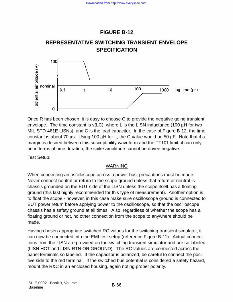
SL-E-0002 - Book 3, Volume 1Baseline B-66
FIGURE B-12
REPRESENTATIVE SWITCHING TRANSIENT ENVELOPESPECIFICATION
Once R has been chosen, it is easy to choose C to provide the negative going transientenvelope. The time constant is v(LC), where L is the LISN inductance (100 µH for twoMIL-STD-461E LISNs), and C is the load capacitor. In the case of Figure B-12, the timeconstant is about 70 µs. Using 100 µH for L, the C-value would be 50 µF. Note that if amargin is desired between this susceptibility waveform and the TT101 limit, it can onlybe in terms of time duration; the spike amplitude cannot be driven negative.
Test Setup:
WARNING
When connecting an oscilloscope across a power bus, precautions must be made.Never connect neutral or return to the scope ground unless that return or neutral ischassis grounded on the EUT side of the LISN unless the scope itself has a floatingground (this last highly recommended for this type of measurement). Another option isto float the scope - however, in this case make sure oscilloscope ground is connected toEUT power return before applying power to the oscilloscope, so that the oscilloscopechassis has a safety ground at all times. Also, regardless of whether the scope has afloating ground or not, no other connection from the scope to anywhere should bemade.
Having chosen appropriate switched RC values for the switching transient simulator, itcan now be connected into the EMI test setup (reference Figure B-11). Actual connec-tions from the LISN are provided on the switching transient simulator and are so labeled(LISN HOT and LISN RTN OR GROUND). The RC values are connected across thepanel terminals so labeled. If the capacitor is polarized, be careful to connect the posi-tive side to the red terminal. If the switched bus potential is considered a safety hazard,mount the R&C in an enclosed housing, again noting proper polarity.
Downloaded from http://www.everyspec.com
SL-E-0002 - Book 3, Volume 1Baseline B-67
The EUT is powered from the same LISN output power port(s) as the switching tran-sient simulator. EUT and STS-1 both look back into the LISN as a common sourceimpedance.
Test Procedures: Once setup is complete, switching transient simulator panel controlsmay be properly adjusted. One knob adjusts the number of transients per unit time.Range is from under one pps to just over 10 pps. The “BUS” switch should be set toDC. “PHASE ANGLE” only applies to AC buses. The knob labeled “TRANSIENTMODE” selects three types of transients. “ON” selects series of the relatively long neg-ative going transients. This simulates many loads being brought on-line sequentially.“OFF” selects a series of the short duration positive spikes. This simulates many loadsbeing turned off sequentially. “ON/OFF” selects a series of alternately appearing nega-tive and positive spikes. “AC POLARITY” only applies to AC buses. The “PULSEENABLE” switch actually commands switching to occur. Actual switching rate may bemonitored before switching is commanded on at the front panel Bayonet Connectorlabeled pps. It is easy to record the transient, even though it is a short duration, lowduty cycle phenomenon. Use a digital oscilloscope (dso) (20 MHz single-event BW -Nyquist criteria - is sufficient). Trigger on a level either above or below nominal withsuitable slope, as appropriate. Use a time per division near the expected transientduration. This will be on the order of 100 µs/division for the negative going transient.
NASA CR-1999-209574 includes test data illustrating the technique with some proto-type switching transient simulators.
5.9 CS114, CONDUCTED SUSCEPTIBILITY, BULK CABLE INJECTION, 10 kHz TO 200 MHz
Applicability and Limits: The requirements are applicable to all electrical cables inter-facing with the EUT enclosures. The basic concept is to simulate currents that will bedeveloped on platform cabling from electromagnetic fields generated by antenna trans-missions both on and off the platform.
An advantage of this type of requirement is that it provides data that can be directlyrelated to induced current levels measured during platform-level evaluations. Anincreasingly popular technique is to illuminate the platform with a low level, relativelyuniform field while monitoring induced levels on cables. Then, either laboratory datacan be reviewed or current injection done at the platform with the measured currentsscaled to the full threat level. This same philosophy has been applied to lightning andEMP testing.
Due to size constraints and available field patterns during RS testing (such as RS103),it has long been recognized that cabling cannot be properly excited to simulate platformeffects at lower frequencies. The most notable example of this situation is experience
Downloaded from http://www.everyspec.com

SL-E-0002 - Book 3, Volume 1Baseline B-68
with HF (2 - 30 MHz) radio transmissions. HF fields have caused numerous problemsin platforms through cable coupling. However, equipment items rarely exhibit problemsin this frequency range during laboratory testing.
The limits are primarily derived from testing on aircraft that were not designed to haveintentionally shielded volumes. The basic structure is electrically conductive; however,there was no attempt to ensure continuous electrical bonding between structure mem-bers or to close all apertures. The shape of the limit reflects the physics of the couplingwith regard to resonant conditions, and the cable length with respect to the interferingfrequency wavelength. At frequencies below resonance, coupling is proportional to fre-quency (20 dB/decade slope). Above resonance, coupled levels are cyclic withfrequency with a flat maximum value. The 10 dB/decade decrease in the limit level atthe upper frequency portion is based on actual induced levels in the aircraft testing database when worst-case measurements for the various aircraft are plotted together. Fromcoupling theory for a specific cable, the decrease would be expected to be cyclic withfrequency with an envelope slope of 40 dB/decade.
The basic relationship for the limit level in the resonance (flat) portion of the curve is 1.5milliamperes per volt/meter that is derived from worst-case measurements on aircraft.For example, 110 dBµA corresponds to 200 volts/meter. At resonance, the effectiveshielding effectiveness of the aircraft can be zero. Application of these results to otherplatforms is reasonable.
The frequency range of 10 kHz to 200 MHz is now standardized for all applications.The optional frequency range of 200 MHz to 400 MHz is deleted because of the ques-tionable validity of performing bulk cable measurements at higher frequencies.
Possible tailoring by the procuring activity for contractual documents is a curve ampli-tude based on the expected field intensity for the installation and a breakpoint for thecurve based on the lowest resonance associated with the platform. Tailoring of thefrequency of application can be done based on the operating frequencies of antenna-radiating equipment. Tailoring should also include transmitters that are not part of theplatform. For equipment used in benign environments, the requirement may not benecessary.
Test procedures: This type of test is often considered as a bulk current test since cur-rent is the parameter measured. However, it is important to note that the test signal isinductively coupled and that Faraday’s law predicts an induced voltage in a circuit loopwith the resultant current flow and voltage distribution dependent on the various imped-ances present.
The calibration fixture with terminations is a 50 ohm transmission line. Since the injec-tion probe is around the center conductor within the fixture, a signal is being induced in
Downloaded from http://www.everyspec.com

SL-E-0002 - Book 3, Volume 1Baseline B-69
the loop formed by the center conductor, the two 50 ohm loads, and the structure of thefixture to which the 50 ohm loads are terminated. From a loop circuit standpoint, thetwo 50 ohm loads are in series, providing a total loop impedance of 100 ohms.Because of the transmission line configuration, inductance effects are minimized.Measurement of induced current levels is performed by measuring a correspondingvoltage across one of the 50 ohm loads. Since the 50 ohm loads are in series for theinduced signal, the total drive voltage is actually two times that being measured.
The actual current that appears on a tested cable from the pre-calibrated drive signaldepends on the loop impedance associated with the cable and the source impedancecharacteristics of the drive probe and amplifier. If the loop impedance is low, such aswould often result with an overall shielded cable, currents greater than those the cal-ibration fixture will result. The maximum required current is limited to 6 dB above thepre-calibration level.
Versions of MIL-STD-462 (superseded by this specification) prior to the “D” revisionincluded a test procedure CS02 which specified capacitive coupling of a voltage ontoindividual power leads. As is the case for this test procedure, CS02 assessed the effectof voltages induced from electromagnetic fields. CS114 improves on CS02 by inducinglevels on all wires at a connector interface simultaneously (common mode) which bettersimulates actual platform use. Also, a deficiency existed with CS02 since the RF sig-nals were induced only on power leads. This test procedure is applicable to all EUTcabling.
Downloaded from http://www.everyspec.com
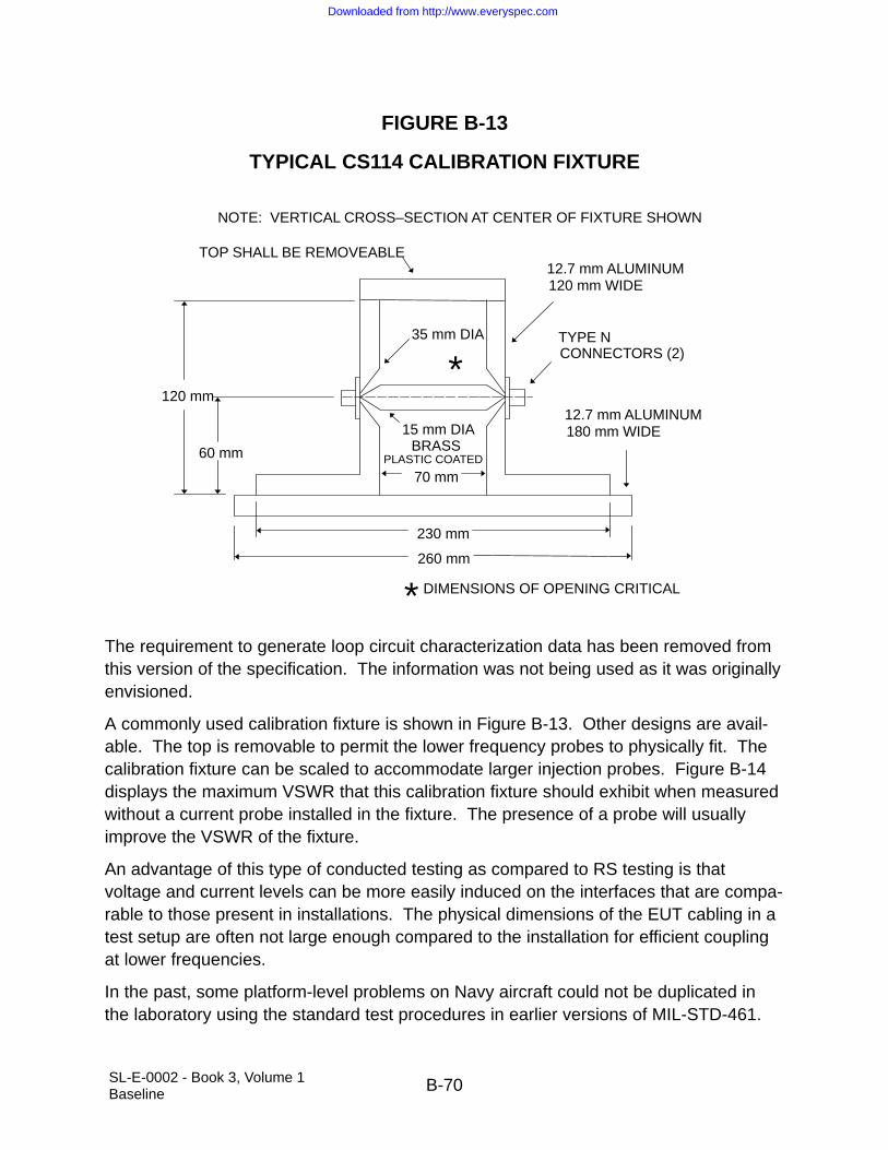
SL-E-0002 - Book 3, Volume 1Baseline B-70
FIGURE B-13
TYPICAL CS114 CALIBRATION FIXTURE
NOTE: VERTICAL CROSS–SECTION AT CENTER OF FIXTURE SHOWN
TOP SHALL BE REMOVEABLE12.7 mm ALUMINUM120 mm WIDE
TYPE NCONNECTORS (2)
12.7 mm ALUMINUM180 mm WIDE
120 mm
60 mm
230 mm
260 mm
*
70 mm
BRASSPLASTIC COATED
35 mm DIA
15 mm DIA
DIMENSIONS OF OPENING CRITICAL*The requirement to generate loop circuit characterization data has been removed fromthis version of the specification. The information was not being used as it was originallyenvisioned.
A commonly used calibration fixture is shown in Figure B-13. Other designs are avail-able. The top is removable to permit the lower frequency probes to physically fit. Thecalibration fixture can be scaled to accommodate larger injection probes. Figure B-14displays the maximum VSWR that this calibration fixture should exhibit when measuredwithout a current probe installed in the fixture. The presence of a probe will usuallyimprove the VSWR of the fixture.
An advantage of this type of conducted testing as compared to RS testing is thatvoltage and current levels can be more easily induced on the interfaces that are compa-rable to those present in installations. The physical dimensions of the EUT cabling in atest setup are often not large enough compared to the installation for efficient couplingat lower frequencies.
In the past, some platform-level problems on Navy aircraft could not be duplicated inthe laboratory using the standard test procedures in earlier versions of MIL-STD-461.
Downloaded from http://www.everyspec.com
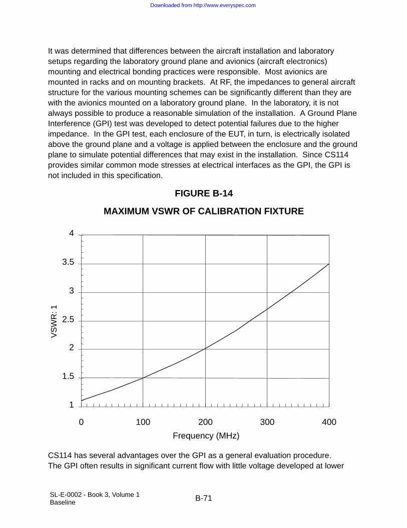
SL-E-0002 - Book 3, Volume 1Baseline B-71
It was determined that differences between the aircraft installation and laboratorysetups regarding the laboratory ground plane and avionics (aircraft electronics)mounting and electrical bonding practices were responsible. Most avionics aremounted in racks and on mounting brackets. At RF, the impedances to general aircraftstructure for the various mounting schemes can be significantly different than they arewith the avionics mounted on a laboratory ground plane. In the laboratory, it is notalways possible to produce a reasonable simulation of the installation. A Ground PlaneInterference (GPI) test was developed to detect potential failures due to the higherimpedance. In the GPI test, each enclosure of the EUT, in turn, is electrically isolatedabove the ground plane and a voltage is applied between the enclosure and the groundplane to simulate potential differences that may exist in the installation. Since CS114provides similar common mode stresses at electrical interfaces as the GPI, the GPI isnot included in this specification.
FIGURE B-14
MAXIMUM VSWR OF CALIBRATION FIXTURE
1
1.5
2
2.5
3
3.5
4
0 100 200 300 400
Frequency (MHz)
VS
WR
: 1
CS114 has several advantages over the GPI as a general evaluation procedure.The GPI often results in significant current flow with little voltage developed at lower
Downloaded from http://www.everyspec.com

SL-E-0002 - Book 3, Volume 1Baseline B-72
frequencies. CS114 is a controlled current test. A concern with the GPI test, which isnot associated with CS114, is that the performance of interface filtering can be altereddue to isolation of the enclosure from the ground plane. The results of CS114 are moreuseful since the controlled current can be compared with current levels present in theactual installation induced from fields. This technique has commonly been used in thepast for certification of aircraft as safe to fly.
FIGURE B-15
INSERTION LOSS MEASUREMENT
MeasurementReceiver
SignalGenerator
Coaxial Load
InjectionProbe
CalibrationFixture
Testing is required on both entire power cables and power cables with the returnsremoved to evaluate common mode coupling to configurations that may be present indifferent installations. In some installations, the power returns are routed with the highside wiring. In other installations, power returns are tied to system structure near theutilization equipment with system structure being used as the power return path.
Insertion loss characteristics of injection probes are specified in Figure 5-16 of the testprocedure. A control on insertion loss has been found to be necessary to obtain consis-tency in test results. Insertion loss is measured as shown in Figure B-15. It is thedifference in dB of the power applied to the probe installed in the calibration fixture andthe power level detected by the measurement receiver. Lower insertion loss indicates
Downloaded from http://www.everyspec.com

SL-E-0002 - Book 3, Volume 1Baseline B-73
more efficient coupling. Since the signal level that is induced in the calibration fixture isequally divided between the 50 ohm coaxial load and the measurement receiver, thelowest possible loss is 3 dB. The use of a network analyzer or measurement receiverthat includes a tracking generator can simplify the measurement.
Techniques using network analyzers or spectrum analyzers with tracking generatorscan simplify the measurements for both Paragraph 5.9.3.4, Step b, calibration andParagraph 5.9.3.4, Step c, EUT testing portions of the procedure. For example, theoutput signal can first be set to a predetermined value such as one milliwatt and the flatness of the signal with frequency can be separately verified through a direct connec-tion to the receiver. With this same signal then applied to the directional coupler, theinduced level in the calibration fixture can be directly plotted.
5.10 CS116, CONDUCTED SUSCEPTIBILITY, DAMPED SINUSOID TRANSIENTS, CABLESAND POWER LEADS, 10 kHz TO 10 MHz
Applicability and Limits: The requirements are applicable to all electrical cables inter-facing with each EUT enclosure and also individually on each power lead. The basicconcept is completely different than the MIL-STD-461E original. For Shuttle usage, thisrequirement is meant to replace the HF aspects of the obsolete CS06 from the previousrevisions of SL-E-0002. The combination of the CS106 requirement and CS116 asmodified for SL-E-0002 is felt to provide adequate simulation of all fast transients likelyto occur on the Shuttle (fast meaning of shorter duration than specified in power qualityspecifications).
The levels and frequency range have been vastly reduced for Shuttle usage from theMIL-STD-461E levels. The requirement levels for this test in MIL-STD-461E could insome cases cause damage to insufficiently protected equipment. The levels for Shuttleusage have been reduced to be commensurate with the obsolete CS06.
A limited set of damped sine waves is specified to address a sampling of the variousringing frequencies that may be present in the platform. An advantage of using a set ofdamped sine waves is that different circuit types are evaluated for various waveformattributes that may cause worst-case effects. Some circuits may respond to peakamplitude while others may respond to total energy or rate of rise.
Test procedures: The calibration fixture with terminations is a 50 ohm transmission line.Since the injection probe is around the center conductor within the fixture, a signal isbeing induced in the loop formed by the center conductor, the two 50 ohm loads, andthe structure of the fixture to which the 50 ohm loads are terminated. From a loopcircuit standpoint, the two 50 ohm loads are in series, providing a total loop impedanceof 100 ohms. Because of the transmission line configuration, inductance effects areminimized. Measurement of induced current levels is performed by measuring a
Downloaded from http://www.everyspec.com

SL-E-0002 - Book 3, Volume 1Baseline B-74
corresponding voltage across one of the 50 ohm loads. Since the 50 ohm loads arein series for the induced signal, the total drive voltage is actually two times that beingmeasured.
Prior to the “D” revision, MIL-STD-462 (superseded by MIL-STD-461E) included testprocedures CS10, CS11, CS12, and CS13, which addressed various types of dampedsine testing on both cables and individual circuits or connector pins. This test proce-dure is a single replacement for all those procedures. CS116 addresses testing ofcables (interconnecting including power) and individual power leads. The commonmode cable portion of the test is the best simulation of the type of condition present on platforms from electromagnetic field excitation. The individual power lead testaddresses differential type signals present on platforms from switching functions occurring in the power system.
As necessary, the test can be applied in a straightforward manner to wires on individualpins on an EUT connector or to individual circuits (twisted pairs, coaxial cables, and soforth).
Since the Q of the damped sine signal results in both positive and negative peaks ofsignificant value regardless of the polarity of the first peak, there is no requirement toswitch the polarity of the injected signal.
The common mode injection technique used in this procedure and other proceduressuch as CS114 is a partial simulation of the actual coupling mechanism on platforms.The magnetic field in the injection device is present at the physical location of the coreof the injection device. In the platform, the electromagnetic field will be distributed inspace. The injection probe induces a voltage in the circuit loops present with thevoltage dropping and current flowing based on impedances present in the loop. Thereis a complex coupling relationship among the various individual circuits within the cablebundle. The injection probe is required to be close to the EUT connector for standard-ization reasons to minimize variations particularly for higher frequencies where theshorter wavelengths could affect current distribution.
For measurement of Q of the injected waveform, Figure 5-19 specifies the use of thepeak of the first half-sine wave and the associated peak closest to being 50% down inamplitude. Some facilities use a damped cosine waveform rather than a damped sine.Since this waveform is more severe than the damped sine because of the fast risetimeon the leading edge, there is no prohibition from using it. Because of potential distortioncaused by leading edge effects, the first peak should not be used to determine Q fordamped cosine waveforms. The next half peak (negative going) should be usedtogether with the associated negative peak closest to 50% down. Equipment mayexhibit failures with this waveform that would not be present with the damped sine.
Downloaded from http://www.everyspec.com

SL-E-0002 - Book 3, Volume 1Baseline B-75
5.11 RE102, RADIATED EMISSIONS, ELECTRIC FIELD, 150 kHz TO 18 GHz
Applicability and Limits: The rationale for an antenna-measured RE requirement con-trolling electric field emissions is to protect sensitive receivers from interference coupledthrough platform antennas connected to platform receivers. Many tuned receivers havesensitivities on the order of one microvolt and are connected to an intentional aperture(the antenna) which are constructed for efficient reception of energy in the operatingrange of the receiver. The potential for degradation requires relatively stringent require-ments to prevent platform problems.
The limits used for the SSV are based on the following criteria:
a. The internal equipment limit depicted in Figure 5-23 is selected to be the sameas MIL-STD-461E limit for internal equipment located in metallic aircraft oflength greater than 25 meters beginning at 200 MHz. This limit is a slight relax-ation of the previously applied limit. The start frequency was based on noknown SSV receivers below 200 MHz.
b. The external equipment limit depicted in Figure 5-25 is selected to be the samelimit as MIL-STD-461E for equipment located external on an aircraft beginningat 200 MHz. This limit is more restrictive than the internal equipment limit sinceexternal equipment may have a more direct line of sight to SSV receivingantennas during critical flight phases.
c. The internal RE limit depicted in Figure 5-24 is the previously titled alternatelimit” from past revisions of this specification (i.e., prior to Revision F). This limitis also in agreement with the payload ICD crew compartment limit. This relaxedinternal limit is deemed acceptable for non-critical equipment because theequipment can be turned off without affecting mission success if the equipmentis found to interfere with Orbiter systems (e.g., wireless crew communicationssystem). It is very important that this limit only be applied to equipment thatdoes not operate during ascent and entry since interference with vehicle com-munication systems during these flight phases could be catastrophic. The useof this limit may need to be reconsidered when new RF communication systemsare operated inside the vehicle (e.g., wireless networks).
Since the SSV does not use the electromagnetic spectrum below 200 MHz for the pur-pose of receiving RF signals, there is no reason to impose the stringent RE102 limitbelow that frequency. Instead, a limit on cable common mode CEs is imposed from 150kHz to 200 MHz. The purpose is to control cable-to-cable crosstalk while at the sametime eliminating the paperwork associated with waivers against an inapplicable RE102limit. Part of the rationale for imposing such a limit is that the SSV often flies quite sen-sitive payloads. These payloads are not as sensitive as the aforementioned radio
Downloaded from http://www.everyspec.com

SL-E-0002 - Book 3, Volume 1Baseline B-76
receivers, but they are orders of magnitude more sensitive than ordinary avionics. Anexample is a crystal growth furnace facility, with control electronics remote from the fur-nace. Thermocouple sensors mounted within the furnace send signals back to theremote controller. Furnace temperature control requirements often dictate that the ther-mocouple reading be accurate to within less than one hundred microvolts.
The BCE limit imposed was designed to limit inductively coupled crosstalk to 1 mV overa frequency range of 150 kHz to 200 MHz. Any victim signal susceptible to millivolt orsub-millivolt level crosstalk will be shielded and the shield may be counted on to providenecessary protection to signals whose accuracy requirement is less than 1 mV.Imposing cable common mode potential control in addition to current conducted emis-sions was considered. For the purpose of minimizing requirements and extra testequipment, this extra method was not included. The current CE requirement shouldsuffice in the vast majority of cases. If a high potential, high impedance common modeculprit is suspected, extra wire separation requirements may need to be taken.
There is no implied relationship between this requirement and RS103 that addressesRS to electric fields. Attempts have been made quite frequently in the past to compareelectric field RE and susceptibility type requirements as a justification for deviations andwaivers. While RE102 is concerned with potential effects with antenna-connectedreceivers, RS103 simulates fields resulting from antenna-connected transmitters.
Often, the same equipment item will be involved in influencing both requirements. A 30watt VHF-AM radio with a typical blade antenna operating at 150 MHz can easily detecta 40 dBµV/m electric field (approximately -81 dBm developed at receiver input) while inthe receive mode. When this same piece of equipment transmits at the same 150 MHzfrequency, it will produce a field of approximately 150 dBµV/m (32 volts/meter) at a 1meter distance. The two field levels are 110 dB apart.
Test procedures: Specific antennas are required by this test procedure for standardiza-tion reasons. The intent is to obtain consistent results between different test facilities.
In order for adequate signal levels to be available to drive the measurement receivers,physically large antennas are necessary. Due to shielded room measurements, theantennas are required to be relatively close to the EUT, and the radiated field is not uni-form across the antenna aperture. For electric field measurements below severalhundred MHz, the antennas do not measure the true electric field.
The biconical and double ridged horn antennas are calibrated using far-field assump-tions at a 1 meter distance. This technique produces standardized readings. However,the true electric field is obtained only above approximately 1 GHz where a far field con-dition exists for practical purposes.
Antenna factors are determined using the procedures of SAE ARP-958. They are usedto convert the voltage at the measurement receiver to the field strength at the antenna.
Downloaded from http://www.everyspec.com

SL-E-0002 - Book 3, Volume 1Baseline B-77
Any RF cable loss and attenuator values must be added to determine the total correc-tion to be applied.
Previous versions of this specification specified conical log spiral antennas. Theseantennas were convenient since they did not need to be rotated to measure both polarizations of the radiated field. The double ridged horn is considered to be better forstandardization for several reasons. At some frequencies, the antenna pattern of theconical log spiral is not centered on the antenna axis. The double ridged horn does nothave this problem. The circular polarization of the conical log spiral creates confusionin its proper application. Electric fields from EUTs would rarely be circularly polarized.Therefore, questions are raised concerning the need for 3 dB correction factors toaccount for linearly polarized signals. The same issue is present when spiral conicalantennas are used for RS testing. If a second spiral conical is used to calibrate the fieldcorrectly for a circularly polarized wave, the question arises whether a 3 dB higher fieldshould be used since the EUT will respond more readily to linearly polarized fields ofthe same magnitude.
Other linearly polarized antennas such as log periodic antennas are not to be used. Itis recognized that these types of antennas have sometimes been used in the past; how-ever, they will not necessarily produce the same results as the double ridged hornbecause of field variations across the antenna apertures and far field/near field issues.Uniform use of the double ridge horn is required for standardization purposes to obtainconsistent results among different test facilities.
The stub radiator required by the procedure is simply a short wire (approximately 10cm) connected to the center conductor of a coaxial cable that protrudes from the end ofthe cable.
The antenna positioning requirements in this procedure are based on likely points ofradiation and antenna patterns. The wavelengths above 200 MHz will result in radiationfrom EUT apertures and portions of cabling close to EUT interfaces. The requirementsfor antenna positioning above 200 MHz are based on including EUT apertures andlengths of cabling at least one quarter wavelength.
All the specified antennas are linearly polarized. Above 30 MHz, measurements mustbe performed to measure both horizontal and vertical components of the radiated field.
For equipment or subsystems that have enclosures or cabling in various parts of a plat-form, data may need to be taken for more than one configuration. For example, in anaircraft installation where a pod is located outside of aircraft structure and its associatedcabling is internal to structure, two different limits may be applicable. Different sets ofdata may need to be generated to isolate different emissions from the pod housing andfrom cabling. The non-relevant portion of the equipment would need to be protectedwith appropriate shielding during each evaluation.
Downloaded from http://www.everyspec.com

SL-E-0002 - Book 3, Volume 1Baseline B-78
Additional commentary relative to the added Space Shuttle BCE requirement:
The test procedure is similar to that for CE101 of MIL-STD-461E, except that signalbundles are also tested, and the power cable as a whole (power input and return) areboth fed through the absorbing clamp to ensure that only common mode emissions aremeasured. The absorbing clamp (fully described in CISPR 16) is a current probe fol-lowed by a series of ferrite ring absorber elements. These act to isolate the rest of thecable, minimizing the standing waves associated with signals on an electrically longmismatched transmission line. If a traditional current probe were used for this testinstead of an absorbing clamp, then at frequencies above which the Cable-under-test(CUT) were greater than one-tenth wavelength long, it would be necessary to physicallyscan the probe the length of the CUT in order to find a peak. Since a 2 meter cable isone-tenth wavelength at 15 MHz, this would entail a convolution of frequency andphysical scanning over a wide frequency range which would result in a long test whichcould not use automated scanning. Use of the absorbing clamp provides repeatableresults using automated test techniques. In order to use the absorbing clamp for thistest, with the current CE limit of this requirement, it must be calibrated as a currentprobe, not as an absorbing clamp per CISPR 16. The manufacturer may be requestedto do this, or it can be done in-house. Calibration is done as per the figure showingmeasurement validation. Instead of a calibration fixture, as described in the CS114 sec-tion, a wire must be connected between signal generator and 50 ohm dummy load.The return path is a ground plane connected between signal generator return anddummy load return. The wire should be as short as possible. Since the absorbingclamp is built per CISPR drawings, and its loss factor as defined in CISPR 16 is fixed,its transfer impedance should also be fixed and be nominally as shown in Figure B-16.
Downloaded from http://www.everyspec.com

SL-E-0002 - Book 3, Volume 1Baseline B-79
FIGURE B-16
NOMINAL TRANSFER IMPEDANCE FCISPR 16 ABSORBING CLAMP
–10
0
10
20
30
0.1 1 10 100
Frequency MHz
In development tests, the absorbing clamp was found to reduce standing wave peaksabout 20 dB from that measured with a traditional current probe. Further, when testingon a shielded cable with well-terminated shields, the absorbing clamp reduced con-ducted emissions by 20 dB even at frequencies where the cable was electrically short.To account for this 20 dB difference between absorbing clamp and traditional currentprobe results, the limit was reduced 20 dB from that resulting from the criterion of lim-iting crosstalk to one millivolt. It is likely that this 20 dB effect would not be presentwhen measuring BCE on a power cable, because it is not shielded and has a relativelyhigh impedance at the lower frequencies. However, in this case, higher current con-ducted emissions would translate into higher cable common mode potentials, so thereis good rationale for imposing the 20 dB safety factor in this case as well.
NOTE: In order to get the full value of the absorbing clamp, it must be placed as closeas possible to the EUT. One-tenth wavelength at 200 MHz is 15 cm. Thisshould be an outer bound on absorber clamp-EUT separation.
5.12 RE103, RADIATED EMISSIONS, ANTENNA SPURIOUS AND HARMONIC OUTPUTS,10 kHz TO 18 GHz
Applicability and Limits: The requirements are essentially identical with CE106 fortransmitters in the transmit mode. There are no requirements for receivers or transmit-ters in the standby mode. Most of the discussion under CE106 also applies to RE103.A distinction between the requirements is that RE103 testing includes effects due toantenna characteristics. The test itself is considerably more difficult.
Downloaded from http://www.everyspec.com

SL-E-0002 - Book 3, Volume 1Baseline B-80
Test procedures: Since the test procedure measures emissions radiating from anantenna connected to a controlled impedance, shielded, transmission line, the mea-surement results should be largely independent of the test setup configuration.Therefore, it is not necessary to maintain the basic test setup described in the mainbody of this specification.
The test procedure is laborious and will require a large open area to meet antenna sep-aration distances. Equations in the test procedure specify minimum acceptableantenna separations based on antenna size and operating frequency of the EUT.Antenna pattern searches in both azimuth and elevation are required at the spuriousand harmonic emissions to maximize the level of the detected signal and account forantenna characteristics.
Sensitivity of the measurement system may need enhancement by use of preamplifiersand the entire test needs to be coordinated with local frequency allocation authorities.All recorded data has to be corrected for space loss and antenna gain before compari-sons to the limit.
As shown in Figure 5-32 and Figure 5-33, shielding might be necessary around themeasurement system and associated RF components to prevent the generation ofspurious responses in the measurement receiver. The need for such shielding can beverified by comparing measurement runs with the input connector of the measurementreceiver terminated in its characteristic impedance and with the EUT in both transmit-ting and stand-by modes or with the EUT turned off. Also, the receiving or transmitantenna may be replaced with a dummy load to determine if any significant effects areoccurring through cable coupling.
The RF cable from the receive antenna to the measurement receiver should be kept asshort as possible to minimize signal loss and signal pick-up.
The band-rejection filters and networks shown in Figure 5-32 and Figure 5-33 areneeded to block the transmitter fundamental and thus reduce the tendency of the mea-surement receiver to generate spurious responses or exhibit suppression effectsbecause of the presence of strong out-of-band signals. These rejection networks andfilters require calibration over the frequency range of test.
Some caution needs to be exercised in applying Table 4.3 of the main body of this specifi-cation. In Paragraph 5.12.3.4, Step d, Item 4, of the test procedure, a power monitor isused to measure the output power of the EUT. In conjunction with the antenna gain, thisvalue is used to calculate the ERP of the equipment. In Paragraph 5.12.3.4, Step d, Item5, of the test procedure, the measurement receiver is used to measure the power from areceiving antenna. This result is also used to calculate an ERP. For the two measure-ments to be comparable, the measurement receiver BW needs to be sufficiently large to
Downloaded from http://www.everyspec.com
SL-E-0002 - Book 3, Volume 1Baseline B-81
include at least 90% of the power of the signal present at the tuned frequency. If the BWin Table 4.3 of the main body of the specification is not appropriate, a suitable measure-ment receiver BW should be proposed in the EMITPs.
For measurement of the magnitude of harmonic and spurious emissions with respect ofthe fundamental, the BWs of Table 4.3 will normally produce acceptable results, regard-less of whether the BW is large enough to process 90% of the power. Since the signalBW of harmonic and spurious emissions is usually the same as the fundamental, use of acommon BW for measuring both the fundamental and the emissions will provide a correctrelative reading of the amplitudes.
5.13 RS103, RS, ELECTRIC FIELD, 10 kHz TO 18 GHz
Applicability and Limits: The requirements are applicable to both the EUT enclosures andEUT associated cabling. The basic concern is to ensure that equipment will operatewithout degradation in the presence of electromagnetic fields generated by antenna trans-missions both onboard and external to the platform.
There is no implied relationship between this requirement and RE102. The RE102 limit isplaced primarily to protect antenna-connected receivers while RS103 simulates fieldsresulting from antenna transmissions.
Using circularly polarized fields is not allowed due to problems with using the spiral con-ical antennas specified in versions of MIL-STD-462 (superseded by this specification)prior to the “D” revision. Circularly polarized fields were convenient since they avoidedthe need to rotate a linearly polarized antenna to obtain both polarizations of the radiatedfield. However, problems existed with this antenna. At some frequencies, the antennapattern of the conical log spiral is not centered on the antenna axis. Also, the circularpolarization of the conical log spiral creates confusion in its proper application. The EUTand associated cabling can be expected to respond more readily to linearly polarizedfields. If a second spiral conical were used to calibrate the field radiated from the firstspiral conical antenna, it would indicate an electric field 3 dB higher than a linearly polar-ized antenna. The question arises whether a 3 dB higher field should be used for a spiralconical transmit antenna to obtain response characteristics similar to a linearly polarizedfield. Similarly, if a spiral conical antenna were used to calibrate a linearly polarized field,the indication would be 3 dB below the true electric field strength.
Test procedures: Test facilities are permitted to select appropriate electric field gener-ating apparatus. Any electric field generating device such as antenna, long wire,transverse electromagnetic cell, reverberating chamber (using mode tuned techniques)or parallel strip line capable of generating the required electric field may be used.Fields should be maintained as uniform as possible over the test setup boundary. Bothhorizontally and vertically polarized fields must be generated. This requirement maylimit the use of certain types of apparatus.
Downloaded from http://www.everyspec.com

SL-E-0002 - Book 3, Volume 1Baseline B-82
Monitoring requirements emphasize measuring true electric field. While emissiontesting for radiated electric fields does not always measure true electric field, sensorswith adequate sensitivity are available for field levels generated for susceptibility testing.Physically small and electrically short sensors are required so that the electric field doesnot vary substantially over the pickup element resulting in the measurement of a local-ized field. Broadband sensors not requiring tuning are available.
The use of more than one sensor is acceptable provided all sensors are within thebeamwidth of the transmit antenna. The effective field is determined by taking theaverage of the readings. For example, if the readings of three sensors are 30, 22, and35 volts/meter, the effective electric field level is (30 + 22 + 35)/3 = 29 volts/meter.
Different sensors may use various techniques to measure the field. At frequencieswhere far-field conditions do not exist, sensors must be selected which have electricfield sensing elements. Sensors that detect magnetic field or power density and con-vert to electric field are not acceptable. Under far-field conditions, all sensors willproduce the same result. Correction factors must be applied for modulated test signalsfor equivalent peak detection as discussed under Paragraph 4.3.10.1. A typical procedure for determining the correction factor for these sensors is as follows:
a. Generate a field at a selected frequency using an unmodulated source.
b. Adjust the field to obtain a reading on the sensor display near full scale andnote the value.
c. Modulate the field as required (normally 1 kHz pulse, 50% duty cycle) andensure the field has the same peak value. A measurement receiver with thepeak detector selected and receiving antenna can be used to make this determination.
d. Note the reading on the sensor display.
e. Divide the first reading by the second reading to determine the correction factor(Subtract the two readings if the field is displayed in terms of dB).
f. Repeat the procedure at several frequencies to verify the consistency of thetechnique.
Above 1 GHz, radiated fields usually exhibit far-field characteristics for test purposes dueto the size of typical transmit antennas, antenna patterns, and distances to the EUT.Therefore, a double ridged horn together with a measurement receiver will provide trueelectric field. Similarly, the particular sensing element in an isotropic sensor is not critical,and acceptable conversions to electric field can be made.
For equipment or subsystems that have enclosures or cabling in various parts of a plat-form, data may need to be taken for more than one configuration. For example, in an
Downloaded from http://www.everyspec.com

SL-E-0002 - Book 3, Volume 1Baseline B-83
aircraft installation where a pod is located outside of aircraft structure and its associatedcabling is internal to structure, two different limits may be applicable. Different sets ofdata may need to be generated to evaluate potential pod susceptibility due to couplingthrough the housing versus coupling from cabling. The non-relevant portion of the equip-ment would need to be protected with appropriate shielding.
Reverberating chambers, using mode tuned techniques, have been popular for per-forming shielded effectiveness evaluations and, in some cases, have been used for RStesting of equipment and subsystems. The concept used in reverberating chambers is toexcite available electromagnetic wave propagation modes to set up variable standingwave patterns in the chamber. A transmit antenna is used to launch a electromagneticwave. An irregular shaped tuner is rotated to excite the different modes and modify thestanding wave pattern in the chamber. Any physical location in the chamber will achievesame peak field strength at some position of the paddle wheel.
Reverberation chambers have the advantage of producing relatively higher fields thanother techniques for a particular power input. Also, the orientation of EUT enclosures isless critical since the all portions of the EUT will be exposed to the same peak field atsome paddle wheel position. The performance of a particular reverberation chamber isdependent upon a number of factors including dimensions, Q of the chamber, number ofavailable propagation modes, and frequency range of use.
Some issues with reverberation chambers are as follows. The field polarization and dis-tribution with respect to the EUT layout are generally unknown at a point in time. If aproblem is noted, the point of entry into the EUT may not be apparent.
Reverberation chambers are sometimes treated as a good tool to determine potentialproblem frequencies with conventional antenna procedures being used to evaluate areasof concern.
The performance of each chamber must be reviewed to determine the suitability of its usefor reverberation testing over a particular frequency range.
Reverberation chambers should be constructed in accordance with the following guidancein order to function properly.
a. A tuner should be constructed of metal and installed with appropriate positioningequipment to allow the tuner to be rotated 360 degrees in at least 200 evenlyspaced increments. The tuner should be constructed to be asymmetric with thesmallest dimension of the tuner being at least λ/3 of lowest frequency to betested and the longest dimension of the tuner being approximately 75% of thesmallest chamber dimension.
Downloaded from http://www.everyspec.com

SL-E-0002 - Book 3, Volume 1Baseline B-84
b. The enclosure should be free of any materials that might exhibit absorptiveproperties such as tables, chairs, wood floors, sub-floors, shelves, and such.Support structures should be constructed from high density foam.
c. Transmit and receive antennas should be at least 1.0 meter (/3 is the actuallimitation) from any wall or object and should be positioned to prevent directalignment between the main lobes of the two antennas or between the EUT andthe main lobe of either antenna.
d. The lower frequency limit is dependent on chamber size. To determine thelower frequency limit for a given chamber, use one of the following methods:
1. Using the following formula, determine the number of possible modes (N)which can exist at a given frequency. If, for a given frequency, N is lessthan 100, then the chamber should not be used at or below that frequency.
N abdfc
= 83
3
3
where: a, b, and d are the chamber internal dimensions in meters f is the operation frequency in Hz c is the speed of propagation (3 x 10⁸ m/s)
2. Use the methods detailed in RTCA DO-160, Section 20.6, for determiningthe lowest useable frequency based on field uniformity.
e. In order to assure that the time response of the chamber is fast enough toaccommodate pulsed waveform testing (other than the 1 kHz, 50% duty cycle,waveform specified), determination of the chamber time constant must beaccomplished using the following procedure:
1. Calculate the chamber Q using:
QV P
PTx Rx
ave rec
forward
=
16 2
3
where ηTx and ηRx are the antenna efficiency factors for the Tx and Rxantennas respectively and can be assumed to be 0.75 for a log periodicantenna and 0.9 for a horn antenna, V is the chamber volume (m3), λ is thefree space wavelength (m) at the specific frequency, Pave rec is the averagereceived power over one tuner rotation, and Pforward is the forward powerinput to the chamber over the tuner rotation at which Pave rec was measured.
Downloaded from http://www.everyspec.com

SL-E-0002 - Book 3, Volume 1Baseline B-85
2. Calculate the chamber time constant, τ, using:
= Qf2
where Q is the value calculated above, and f is the frequency (Hz)
3. If the chamber time constant is greater than 0.4 of the pulse width of themodulation waveform, absorber material must be added to the chamber orthe pulse width must be increased. If absorber material is added, repeatthe measurement and the Q calculation until the time constant requirementis satisfied with the least possible absorber material. A new CLF() mustbe defined if absorber material is required.
f. Prior to using the chamber, the effectiveness of the tuner should be evaluatedat the upper and lower frequencies to be used and at points between the end-points not to exceed 1 GHz spacing. To evaluate the stirring effectiveness,inject a CW signal into the chamber at the desired frequency and record the netreceived power at 200 positions of the tuner evenly spaced over a 360 degreerotation of the tuner. Determine the correlation coefficient between the originalset of received power and subsequent sets obtained by rotating the last datapoint of the original set to the position of the first point and then shifting all theother points to the right as depicted below.
Original data D1, D2, D3, D4, D5, . . . D200
Shifted data (1) D200, D1, D2, D3, D4, . . . D199
Shifted data (2) D199, D200, D1, D2, D3, . . . D198
Shifted data (3) D198, D199, D200, D1, D2, . . . D197
Shifted data (4) D197, D198, D199, D200, D1, . . . D196
Shifted data (5) D196, D197, D198, D199, D200, D1, . . . D195
The correlation coefficient should drop to below 0.36 within five shifts of the data.This will ensure that the tuner is operating properly. If the tuner fails this test, thenthe tuner needs to be made either larger or more complex, or both.
g. National Bureau of Standards Technical Note 1092, “Design, Evaluation, andUse of a Reverberation Chamber for Performing Electromagnetic Susceptibility/Vulnerability Measurements” and National Institute of Standards andTechnology Technical Note 1508, “Evaluation of the NASA Langley ResearchCenter Mode-Stirred Chamber Facility,” should be used as a guide in preparinga shielded room for reverberation measurements.
Downloaded from http://www.everyspec.com

SL-E-0002 - Book 3, Volume 1Baseline B-86
5.14 TT101, CONDUCTED EMISSIONS, TIME DOMAIN, DC POWER LEADS, TRANSIENTAND STEADY-STATE
Applicability and Limits: Several issues are potentially of interest when cycling loadson/off a power bus. This method addresses voltage transients on the bus due transmis-sion line characteristics of power bus wiring. Another issue is inrush current, which isan important consideration on some types of loads and also when power source is cur-rent limited, such as on the Shuttle 400 Hz bus. The Shuttle DC bus is powered from afuel cell, which is a very low resistance (stiff) source of power. Loading the fuel cellitself is not an issue. Reactive and resistive effects of a long distributed power bus isthe concern. There have been several cases noted where energizing certain equip-ment has dropped bus potentials for durations of the order of 100 µs, causing otherequipment to malfunction.
There are also a few cases where high current loads generate periodic spikes on thepower bus, such as hydraulic pumps near the aft end of the cargo bay. The steady-state ripple requirement is imposed to limit such spikes.
For a detailed discussion of the physics of switching transients, see NASACR-1999-209574.1 Considering the nature of a power bus, it is impossible for a tran-sient to cause line voltage to cross zero from whatever polarity the nominal line voltagehappened to be at instant of turn-on. There is no justification for a DC limit below zero.In essence there is no justification for an amplitude-based safety margin. Margins mustbe based on duration only. For a turn-off transient, the only limit is the characteristicimpedance of the LISN multiplied by the switched current. The duration is fixed bychoice of LISN. Hence, picking a limit comes down to deciding how much DC load cur-rent can be switched off at once.
The steady-state limit of 0.7 Volt peak departure from nominal bus potential in a 10MHz BW was picked to provide a 0.5 Volts root mean square (Vrms) sine wave equiva-lent time domain ripple. In practice, the rms equivalent will be much less. The 0.5Vrms number provides reasonable margin with respect to imposed susceptibilityrequirements.
Test procedures: The LISN defined herein for the purpose of this test is different thanthe LISN defined for CE102. Whereas the CE102 LISN provides a defined impedancebetween power conductor and ground, the TT101 LISN provides a defined impedancebetween each 28 VDC power conductor. Impedance to ground is uncontrolled. Neces-sarily, the measurement is made line-to-line, which imposes certain restrictions on how
1 NASA Center for AeroSpace Information, 800 Elkridge Landing Road, Linthicum Heights,MD 21090-2934 301/621-0390 or National Technical Information Service, 5285 Port RoyalRoad, Springfield, VA 22161 703/487-4650
Downloaded from http://www.everyspec.com

SL-E-0002 - Book 3, Volume 1Baseline B-87
the oscilloscope is used, which is discussed below. In this revision of SL-E-0002, thedefault series resistance of the LISN has been reduced an order of magnitude, to25 mΩ in each leg, to more correctly reflect the character of the transient where it is ofmost interest, at the point where the transient is impressed on other victim loads. Otherthings equal, a transient waveform will return to nominal much more quickly with thelower bus resistance. Users of commercially procured LISNs should be aware theywere likely built to older revisions and will require modification for testing to the newerstandard. The default resistance value of 25 mΩ is reasonable for EUTs which presenta light load to the power bus. In general, the total series resistance (sum of resistancesin both LISN conductors) should be such that EUT current causes a 0.1 Volt steady-state drop across the LISN series resistance.
A solid-state switch to energize/de-energize EUT is a necessity in order to avoid theinevitable bouncing and/or arcing associated with mechanical switching. Instructions onhow to build such a switch may be found in NASA CR-1999-209574.
A digital storage oscilloscope (10 MHz single event BW) is highly desirable for bothtransient and steady-state measurements. It is necessary to record transient wave-forms such that undisturbed line voltage is displayed before and after the transientevent. A dso is the most convenient method of capturing the waveform. The advan-tage of a dso for this measurement is in ease of triggering. A digital oscilloscope’striggering function is almost opposite in function to that of an analog oscilloscope, inthat an analog oscilloscope does not record data until the specified trigger event occurs.The dso, by contrast, can be set to continually record data to memory until the triggerevent occurs. When the trigger event occurs, the dso ceases to take data once itsmemory has filled. Thus, data taken prior to trigger event can be recorded, assuring acomplete record of the transient event leading edge. A dso also has the capability torecord continuously in a max or peak hold mode, which is what is needed for thesteady-state measurement.
Because the LISN inserts impedances in both 28 VDC power conductors, it is essentialthat the oscilloscope measurement not ground the low side conductor. With a groundedchassis dso, this means a differential measurement (channel A - channel B) must bemade. A better solution is to use a portable isolated chassis dso, in which the groundside of the oscilloscope probe is floating.
The switch should be placed between LISN and EUT. There is often confusion aboutthis. The switch cannot be placed on the power input side of the LISN or else all that ismeasured is the filtering effect of the LISN on a switched input. The purpose of the testis to measure bus voltage transients when a load is switched on or off the bus as mod-eled by the LISN itself.
Calibration is extremely important for the transient measurement. If triggering is incor-rectly set up, no emission will be found. A resistive load drawing the same DC current
Downloaded from http://www.everyspec.com

SL-E-0002 - Book 3, Volume 1Baseline B-88
as the EUT will normally provide a smaller turn-on transient than the EUT itself, hencethe ability to measure the transient associated with that resistor indicates a proper testset up.
The transient limit allows that once a load is turned on and drawing a DC current, thatthe turn-on transient does not return to the open circuit voltage which appeared at theoutput of the LISN prior to turn-on, but rather returns to a loaded potential which is theopen circuit potential less the DC resistance of the LISN multiplied by the EUT load current. However, if the transient waveform does not return to this level, or takesexcessive time to do so, it may mean there are other sources of DC or AC impedancesbetween power source and LISN. If an EUT fails to meet the turn-on transient limit dueto excessive time to return to nominal, troubleshooting the test set up should precederedesign of the EUT. Measure the transient waveform on the power input side of theLISN. It should be non-existent or small enough it does not contribute to the non-compliance. If such is not the case, steps must be taken to lower the power sourceimpedance. The most obvious technique is to shorten the length of power leadsbetween power supply and LISN. This can be especially effective if power source isoutside of a shield room with filtered power, and providing power from within the roombypasses those filters.
The major source of the transient voltage drop and duration is the charging of a bulkcapacitor in the EUT. If this capacitor is partially charged, the measured transient issmaller than if the capacitor is completely discharged. A one second period should beallowed after EUT has been de-energized before measuring a turn-on transient, in orderto ensure complete discharge of bulk capacitor.
The steady-state limit measures departures from nominal bus potential. The issue ofhow long to test is based on EUT cycle times. If the EUT performs different functions atdifferent times, then it is necessary to lengthen the acquisition time to cover the totalcycle. In the event that only one portion of the cycle generates above limit emissions, itmay be useful to note that fact when considering how to address the problem.
Downloaded from http://www.everyspec.com