
Specification and Validation of Non-Functional … Validation of Non-Functional Constraints Johan...
12
Specification and Validation of Non- Functional Constraints Johan Lindqvist, Dragos Truscan, Johan Lilius, Ivan Porres and Timo O. Eriksson Introduction Specification Method Testing Method Conclusions Specification and Validation of Non-Functional Constraints Johan Lindqvist 1 , Dragos Truscan 1 , Johan Lilius 1 , Ivan Porres 1 and Timo O. Eriksson 2 1 Turku Center for Computer Science, Abo Akademi University, Turku, FINLAND 2 Nokia Research Center, Helsinki, FINLAND Artist workshop on Foundations of Component-Based Design October 4, 2007 1/20 Specification and Validation of Non- Functional Constraints Johan Lindqvist, Dragos Truscan, Johan Lilius, Ivan Porres and Timo O. Eriksson Introduction Specification Method Testing Method Conclusions Changes in the Environment of Mobile Device Manufacturing •Modem platform •Wireless standards •Application platform •Peripherals •Value domain SW/HW •Core applications •Operating Systems •Integration/assembly Nokia Motorola, Samsung Sony-Ericsson, LG 2000 2010 Nokia Docomo Ericsson Linux Microsoft Symbian Qualcomm Nokia TI Intel Samsung Intel STm TI Microsoft Nokia Epson Samsung Toshiba Flextronics Huawei Nokia Motorola Samsung Sony Philips STm Microsoft Nokia Real Qualcomm ATI Tron Qualcomm Philips ARM Googl Palm IBM Matsushita SUN Qualcomm Apple Renesas Figure 2. Mobile industry shift from vertical to horizontal mode. (Company names in diagram are examples and are for illustration only). From [Suo06] October 4, 2007 1/20
Transcript of Specification and Validation of Non-Functional … Validation of Non-Functional Constraints Johan...

Specificationand Validation
of Non-FunctionalConstraints
JohanLindqvist,
DragosTruscan,
Johan Lilius,Ivan Porres
and Timo O.Eriksson
Introduction
SpecificationMethod
TestingMethod
Conclusions
Specification and Validation of Non-FunctionalConstraints
Johan Lindqvist1, Dragos Truscan1, Johan Lilius1, IvanPorres1 and Timo O. Eriksson2
1Turku Center for Computer Science, Abo Akademi University, Turku,FINLAND
2Nokia Research Center, Helsinki, FINLAND
Artist workshop on Foundations of Component-BasedDesign
October 4, 2007 1/20
Specificationand Validation
of Non-FunctionalConstraints
JohanLindqvist,
DragosTruscan,
Johan Lilius,Ivan Porres
and Timo O.Eriksson
Introduction
SpecificationMethod
TestingMethod
Conclusions
Changes in the Environment of Mobile DeviceManufacturing
2. New requirements for platforms and architectures
Although digital convergence means industry level convergence in features and technologies it introduces new level of divergence and system level complexity. Furthermore, in many companies this has also impact to product portfolio by increasing the number of different products. In foreseeable future mobile phone manufacturers have transformed themselves to be mobile device manufacturers with tens if not hundreds of different products. This kind of diversification is introducing new set of requirements for architectures and platforms. Some of the key requirements are:
Modularity Flexibility Scalability
Efficient horizontal business model brings some new important requirements. To enable re-use and third party development we need to solve the issue of verification. It should be possible to verify and validate the module independently of the rest of the system. In practice this means that vendor can be responsible of the whole functionality of the module up to the full verification and validation.
Communication and applied interfaces need to be specified in a manner that neither party should need to know internals of the other communicating party. This black-box requirement is the essential one. With black-box requirement we end up to the requirementof loose coupling which supports well the sound
design principle of separating the communication function and the actual processing.
One important driver for horizontal mode of development is the opportunity for open innovation. Freedom to do out-of-box innovations in subsystem level R&D is one source of increased efficiency. Architecture lending itself well for utilization of heterogeneous technologies can exploit the latest innovations in the industry. This feature will also extend the life time of the architecture by embedding the inherent capability for renewal.
Mobility, portability and scalability are setting up one very special requirement for architecture and especially to its realizations. It is good to remind here that speaking about true modularity implies the modularity in different level of abstractions too. Subsystems and their interfaces seen on functional and logical level need to exist also in the level of physical architecture and reflect modularity there. However, here we are not saying anything about level of integration. On the contrary it is of vital importance that in portable devices we have freedom to select the right integration level. In our toolbox we need to have option to pack modules into separate boxes, to multiple ICs, chips stacked into one package or into one die with all the benefits of the SoC level integration. Furthermore, this should happen without breaking the architecture and still maintaining the model of communication.
In addition to requirements mentioned above there will be couple of common set of requirements applicable for the most of mobile devices. Due to the increasing
•Modem platform •Wireless standards •Application platform •Peripherals •Value domain SW/HW •Core applications •Operating Systems •Integration/assembly
Nokia
Motorola, Sam
sung
Sony-Ericsson, LG
2000 2010
Nokia Docomo Ericsson
Linux Microsoft Symbian
Qualcomm Nokia TI Intel Samsung
Intel STm TI
Microsoft Nokia
Epson Samsung Toshiba
Flextronics Huawei Nokia Motorola Samsung
Sony Philips STm Microsoft Nokia Real Qualcomm
ATI
Tron
Qualcomm PhilipsARM
GooglPalm IBM
Matsushita
SUN
Qualcomm
Apple
Renesas
Figure 2. Mobile industry shift from vertical to horizontal mode. (Company names in diagram are examples and are for illustration only).
!"#$%%&'()*+#,+-.%+/-.+01"#2'$"#+3#(,%"%($%+#(+4')'-56+78*-%2+4%*')(+9474:;<=+
;>?</@>A<;/>BC;<+DA;E;;+F+A;;<!!"""#
!"#$%%&'()*+#,+-.%+/-.+01"#2'$"#+3#(,%"%($%+#(+4')'-56+78*-%2+4%*')(+9474:;<=+
;>?</@>A<;/>BC;<+DA;E;;+F+A;;<!!"""#
From [Suo06]
October 4, 2007 1/20
Specificationand Validation
of Non-FunctionalConstraints
JohanLindqvist,
DragosTruscan,
Johan Lilius,Ivan Porres
and Timo O.Eriksson
Introduction
SpecificationMethod
TestingMethod
Conclusions
What does this imply for Design Methods?
importance and the amount of digital content the communication and storage solutions will be in key role defining the winning architecture for mobile devices. Currently data processing units are in central role defining the architecture while in coming years there will be significant shift from processor centric architecture thinking towards content and communication centric architectures.
One important requirement has been the low power consumption and the constraints set by heat dissipation – that is a requirement which remains and will be even more challenging source for requirements in the future. Also the overall security and trust regarding both the content and the platform are important issues to be taken care.
Mitigating complexity by increasing modularity is usually revealing new challenges in system level. To cope with those system level issues we need to take care that appropriate system level tool and methodology framework is properly set up.
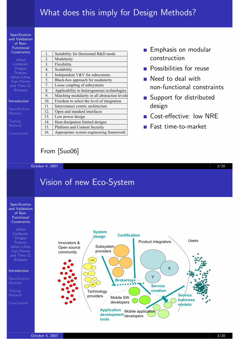
In the following list we have collected all mentioned requirements into one table (Table 1.)
Table 1 List of high level requirements for the future mobile device architectures
1. Suitability for Horizontal R&D mode 2. Modularity 3. Flexibility 4. Scalability 5. Independent V&V for subsystems 5. Black-box approach for modularity 7. Loose coupling of subsystems 8. Applicability to heterogeneous technologies 9. Matching modularity in all abstraction levels
10. Freedom to select the level of integration 11. Interconnect centric architecture 12. Open and standard interfaces 13. Low power design 14. Heat dissipation limited designs 15. Platform and Content Security 16. Appropriate system engineering framework
3. Service oriented modular device architecture
Based on above set of requirements we have extracted couple of key foundations for new mobile device architecture. Intention of opening this new system level architecture is to jointly with academia and industry create open mobile device architecture enabling new level modularity and speeding up open innovation in industry. Open architecture means here open core system solutions like interconnect and key concepts like way of specifying services still leaving lots of space for competition in implementations and new technologies and of course in defining new innovative services. The proposed draft for the architecture is called Network on Terminal Architecture – NoT A.
We are emphasizing that primary meaning of modularity is not based on HW level modularity. The concept of modularity need to be visible already on system level. This implies that both functional and logical architecture need to express matching modularity.
3.1. Functional Architecture
On functional level the basic entities are the nodes providing services and the “application” nodes consuming provided services. Architecture it self consist of set of services or service nodes (SN) and set of use case driven application nodes (AN).Furthermore, we need a concept for communication solution which we call as interconnect. In Figure 3. we are depicting the proposed architecture in functional level.
Figure 3 Functional description of service based architecture.
!"#$%%&'()*+#,+-.%+/-.+01"#2'$"#+3#(,%"%($%+#(+4')'-56+78*-%2+4%*')(+9474:;<=+
;>?</@>A<;/>BC;<+DA;E;;+F+A;;<!!"""#
!"#$%%&'()*+#,+-.%+/-.+01"#2'$"#+3#(,%"%($%+#(+4')'-56+78*-%2+4%*')(+9474:;<=+
;>?</@>A<;/>BC;<+DA;E;;+F+A;;<!!"""#
From [Suo06]
Emphasis on modularconstruction
Possibilities for reuse
Need to deal withnon-functional constraints
Support for distributeddesign
Cost-effective: low NRE
Fast time-to-market
October 4, 2007 2/20
Specificationand Validation
of Non-FunctionalConstraints
JohanLindqvist,
DragosTruscan,
Johan Lilius,Ivan Porres
and Timo O.Eriksson
Introduction
SpecificationMethod
TestingMethod
Conclusions
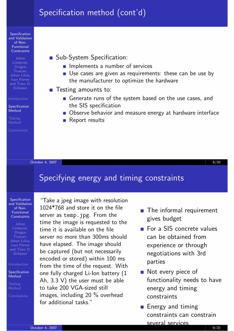
Vision of new Eco-System
X
Y
UsersProduct integrators
Mobile applicationdevelopers
Mobile SWdevelopers
Subsystemproviders
LCD
uP
Technologyproviders
Innovators &Open sourcecommunity
Certification
Servicebusinessmodels
Brokering
Systemdesign
Applicationdevelopmenttools
Servicecreation
October 4, 2007 3/20

Specificationand Validation
of Non-FunctionalConstraints
JohanLindqvist,
DragosTruscan,
Johan Lilius,Ivan Porres
and Timo O.Eriksson
Introduction
SpecificationMethod
TestingMethod
Conclusions
NoTA
NoTA (Network on Terminal Architeture) is Nokia’s attempt ataddressing the challenge.Consists of 2 parts:
A device architecture
Service based,Network centric,Loosely coupled,Follows GALS principles
A design method
SOA-basedIdentification of ServicesDefinition ofSubsystemsDefinition of Tests
For subsystemtestingFor integrationtesting
October 4, 2007 4/20
Specificationand Validation
of Non-FunctionalConstraints
JohanLindqvist,
DragosTruscan,
Johan Lilius,Ivan Porres
and Timo O.Eriksson
Introduction
SpecificationMethod
TestingMethod
Conclusions
NoTA Logical Architecture
A Method for Mobile
Terminal Platform
Architecture Development
Klaus Kronlöf, Samu Kontinen, Ian
Oliver and Timo Eriksson
Nokia Research Center
P.O.Box 407, FI-00045 NOKIA GROUP,
Finland
Abstract We introduce a novel architecture, called the
Network-on-Terminal Architecture (NoTA), for mobile
terminal platforms. This paper concentrates on the
platform development and validation flow adopted for
NoTA. Platform requirements are expressed as use cases
that are modelled using UML2 with Telelogic's Tau G2
tool. Models are executable so that use case behaviour
can be animated. Use cases are used as test cases in the
platform architecture development for which use case
information is transferred as execution traces. We use
CoFluent Studio tool for platform architecture
specification and performance analysis. The use case
execution trace is fed into a functional model that
represents the computation load. NoTA is service
oriented and thus the functional model consists of
platform services. The computation and communication
resources are modelled with a separate platform
architecture model. The tool allows exploring different
configurations and allocations of the functional and
platform models quickly and provides extensive
performance information, including power consumption.
1 Motivation
Digital convergence and mobile device industry
horizontalisation are creating pressure for companies to
renew their competences as well as the device
architecture. Current CPU centric highly integrated one-
for-all-platforms have come to the end of the road.
Future mobile device architectures are system-wise
modular and service based. Network On Terminal
Architecture (NoTA) is such an architecture.
The development of mobile terminal platforms
should start from end-user needs. In our company we
have traditionally expressed them as use cases. For
NoTA we have developed a more rigorous model-based
method of presenting use cases and using them to guide
platform architecture development. The method also
utilizes the service oriented nature of NoTA to form an
intermediate functional model between abstract use cases
and the platform architecture solution.
In the method we use commercial tools and standard
modeling languages as much as possible. The innovation
is in integrating them to support use case driven
development of service oriented platform architectures.
2 Introduction to NoTA
NoTA is an interconnect centric modular service-based
architecture for today’s and future mobile device
platforms. NoTA claims to provide superior performance
and to make effective horizontalisation possible via
eased integration. The development method associated
with NoTA ensures that designs are stepwise verifiable
against end-user requirements. The method is also
flexible and scaleable with reuse on different levels.
NoTA allows the use of novel technologies and open
innovation, and shortens the R&D cycle.
A NoTA platform consists of loosely connected
services running on top of heterogeneous sub-systems. In
NoTA based systems all service and data communication
is routed via the network stack as shown in Figure 1; this
approach is similar to that taken formerly by CORBA
[OMG95] and lately in a more sophisticated form by
Web Services [Erl05]. NoTA takes these principles and
specialises them for use in a highly embedded system.
The NoTA method includes a platform development
flow that ensures that services, sub-systems and the
interconnect topology are matched to end-user
requirements. It also provides formal reusable
specifications for the platform entities.
Figure 1: NoTA logical architecture consisting of three
types of foundation elements called Application Nodes,
Service Nodes and Interconnect
From: [KKE06]October 4, 2007 5/20

Specificationand Validation
of Non-FunctionalConstraints
JohanLindqvist,
DragosTruscan,
Johan Lilius,Ivan Porres
and Timo O.Eriksson
Introduction
SpecificationMethod
TestingMethod
Conclusions
NoTA Device Architecture
NoTA defines two main level of protocols for the
interconnect, called H_IN and L_IN. H_IN is a high
level protocol stack providing communication
functionality for platform services and applications.
L_IN is the low level protocol that provides the physical
connection between subsystems.
A NoTA subsystem implements a set of services. It is
an architectural concept that does not necessarily align
with chip boundaries. So, we may have several
subsystems on a chip and a subsystem may extend
outside the boundaries of a chip, as illustrated in Figure
2.
Figure 2: Example of physical implementation of NoTA
based platform
3 NoTA Platform Architecture
Development Method
The industrial practice in platform architecture
development is quite informal and heavily relies on
system architect’s experience. This is feasible when
changes in successive generations of the architecture are
relatively small, but is problematic when dealing with
truly novel architectural concepts that call for systematic
exploration of quite different alternatives. Furthermore,
platform requirements are typically expressed in
technical terms that are not properly connected to end-
user needs. The NoTA platform architecture
development method aims at overcoming these pitfalls of
industrial practice.
NoTA based systems are engineered in a systematic
requirements driven manner. It is characterised by the
following principles.
Separation of concerns: We want to be able to
develop different aspects of the system independently
from each other in order to manage complexity and to
facilitate reuse. In the NoTA method we separate the
domains of:
! end-user requirements
! platform functionality, i.e., services provided by
the platform
! platform architecture, i.e., definition of subsystems
and communication infrastructure [Bas03]
! implementation of subsystems (SW and HW) and
interconnect protocols (SW and HW).
Each of the domains has their own self-contained
models. Eventually, in the final system, these domains
are of course related to each other, but we want to be
able to postpone fixing these relations until the time we
actually define the system instance (that can be a product
or a product platform).
Model-based engineering: In the NoTA method the
artefacts developed in different phases of the process are
models with well-defined semantics. We want to avoid
misunderstandings and the consequent errors caused by
ambiguousness and hidden meanings of informal
documentation. We also want to be able to use analysis,
verification, transformation, code generation and
synthesis tools that operate on models.
Reuse of models: We believe that the possibility to
effectively reuse models in different contexts gives a big
improvement of design productivity compared to
conventional methodologies. In the NoTA method
different kinds of models are stored in repositories from
where they can be retrieved and used to compose new
system configurations. We have put special emphasis on
modelling techniques that enable easy composition of
models.
Early validation and verification: One motivation
of model-based engineering is early validation and
verification of specifications and designs. In the NoTA
method the validation and verification starts already at
end-user requirements phase with executable use case
models. Later on, its focus is on the correctness of
platform specification and performance analysis at both
specification and implementation phases. In the NoTA
method, the validation and verification is not limited to
logical correctness, but covers also non-functional
aspects, such as real-time performance and energy
consumption.
4 Requirements Modelling
In NoTA we have taken a use case driven approach to
requirements modelling. Generally speaking, a use case
captures a contract between the stakeholders of a system
about its behaviour [Coc00]. It describes the system’s
behaviour under various conditions as it responds to a
request from one of its stakeholders, called the primary
actor. The primary actor initiates an interaction with the
system to accomplish some goal.
The classical use case approaches [Coc00]
concentrate on specifying system functionality by means
of action sequences. We have developed these
approaches further because we feel that it is essential to
Example NoTA device architecture from: [KKE06]October 4, 2007 6/20
Specificationand Validation
of Non-FunctionalConstraints
JohanLindqvist,
DragosTruscan,
Johan Lilius,Ivan Porres
and Timo O.Eriksson
Introduction
SpecificationMethod
TestingMethod
Conclusions
Specification method
SIS
Build Sub-system
Library
Specify Use Cases (Scenarios)
Identify Services
Specify Service
Interaction
Define Service Protocol
Partition Services
Select DOA Data Handling
MIME DOA
Library
Service Library
Subsystem Library
Requirements
Interface Specification
(WSDL)
Data Comm. Specification (DOA_FSM)
Behavior Specification
(FSM)
Subsystem Specification
Build System
Testing Specifications
System Specification
Document Generation
HTML
Build Service Library
Use Case Library
The NoTA Design flow
October 4, 2007 7/20
Specificationand Validation
of Non-FunctionalConstraints
JohanLindqvist,
DragosTruscan,
Johan Lilius,Ivan Porres
and Timo O.Eriksson
Introduction
SpecificationMethod
TestingMethod
Conclusions
Specification method (cont’d)
Sub-System Specification:
Implements a number of servicesUse cases are given as requirements: these can be use bythe manufacturer to optimize the hardware
Testing amounts to:
Generate runs of the system based on the use cases, andthe SIS specificationObserve behavior and measure energy at hardware interfaceReport results
October 4, 2007 8/20
Specificationand Validation
of Non-FunctionalConstraints
JohanLindqvist,
DragosTruscan,
Johan Lilius,Ivan Porres
and Timo O.Eriksson
Introduction
SpecificationMethod
TestingMethod
Conclusions
Specifying energy and timing constraints
“Take a jpeg image with resolution1024*768 and store it on the fileserver as temp.jpg. From thetime the image is requested to thetime it is available on the fileserver no more than 300ms shouldhave elapsed. The image shouldbe captured (but not necessarilyencoded or stored) within 100 msfrom the time of the request. Withone fully charged Li-Ion battery (1Ah, 3.3 V) the user must be ableto take 200 VGA-sized stillimages, including 20 % overheadfor additional tasks.”
The informal requirementgives budget
For a SIS concrete valuescan be obtained fromexperience or throughnegotiations with 3rdparties
Not every piece offunctionality needs to haveenergy and timingconstraints
Energy and timingconstraints can constrainseveral services
October 4, 2007 9/20

Specificationand Validation
of Non-FunctionalConstraints
JohanLindqvist,
DragosTruscan,
Johan Lilius,Ivan Porres
and Timo O.Eriksson
Introduction
SpecificationMethod
TestingMethod
Conclusions
Energy Properties
Power constraints associated to states
Mean power, Peak power
Important to understand how power is used over timeMean power requires tests to be run several timesStatistical measures of variation can also be included
Energy and timing constraints associated to transitions
{wakeup, shutdown} {energy, time} for services
October 4, 2007 10/20
Specificationand Validation
of Non-FunctionalConstraints
JohanLindqvist,
DragosTruscan,
Johan Lilius,Ivan Porres
and Timo O.Eriksson
Introduction
SpecificationMethod
TestingMethod
Conclusions
Use Case: Take Single Picture
DOATransfer:DOAEnc:JPEGEncoderSC:StillCapture FS:FileServerApp:Application
sd: UC1.Take single picture.Interaction_1.1
.OpenFile_req("temp.jpg")
.OpenFile_cnf(0,handleFS)
.Capture_req(1024,80,handleFS)
.Encode_req(1024,80,handleSC,handleFS)
.CaptureReady_ind(0)
.Encode_cnf(0,handleFS)
.Capture_cnf(0,handleFS)
.Receive(handleFS,DOA_FileServer_any_in)
.Send(handleFS,DOA_JPEGEncoder_jpg_out,size < 500000 and size > 1000)
.Receive(handleSC,DOA_JPEGEncoder_bmp_in)
.Send(handleSC,DOA_StillCapture_bmp_out,size = 2359350)
<300ms
<100ms
<47J
<1J
<90ms
<290ms
<200ms
<40ms
<30ms
<10ms
<130ms
<10J
<8J<16J
IDLE
CAPTURE1
STORING
IDLE
ENCODING
IDLE
IDLE
IDLE
OPENING
IDLE
<12J
Figure 6. Interaction diagram for use case UC1. Take single picture
confirming that a photo has been taken and transferred to theEnc::JPEGEncoder, and then with a Capture cnf mes-sage to announce that the JPEG encoded photo has beenstored on the FileServer.
As shown earlier, energy and timing requirements may beassociated with each use case. When the use case spans sev-eral subsystems, these requirements must be decomposed toformulate verifiable deadlines and energy budgets for the usecase portions executed by the individual subsystems. Such adecomposition is shown in Figure 6. To explore the possibil-ities to verify these decomposed constraints in practice, wehave set up an experimental energy consumption test bench.
The data transfers between services are modeled as inputand output streams over the DOA Interconnect, accompaniedby parameters describing the transferred data.
4 Tool Support
As previously mentioned, in our subsystem specificationapproach we employ both a graphical and a textual specifica-tion format. The definitions of the two formats are indepen-dent, yet they are equivalent. The graphical representationformat has been defined using a metamodel and implementedin the Coral modeling tool [4], whereas the XML-based rep-resentation has been defined using an XML Schema.
Figure 7 shows a caption of Coral editing the FSM of theStillCapture service. We find that especially the protocolstate machines and the interaction sequences modeling usecases are far easier to construct and understand using thisgraphical view of the specifications.
The subsystem, service interface and use case specifica-tions are primarily exchanged between the system designerand vendors as XML files. Although most aspects of thesespecifications may be successfully edited and validated usingany schema-conscious XML editor, we employ Coral to au-tomatically generate the XML-based specification from theexisting graphical representations. For instance, the follow-ing XML code specifies the Imaging subsystem shown inFigure 2.
Figure 7. StillCapture FSM in Coral
<?xml version="1.0" ?> <Subsystem xmlns="http://mde.abo.fi/NoTASpec/0.1/System/Subsystem"name="Imaging"><documentation>This is the imaging subsystem, containing services related to image capture, encoding,editing etc.
</documentation><usecase>UC1 - Take single picture</usecase><usecase>UC2 - Take picture series</usecase><service name="StillCapture" specification="StillCapture"><documentation>Captures pictures using a camera and encodes them as bmp, no compression, 1280*960.May use encoder services to supply other file formats and image sizes.
</documentation><sequence>Seq1.1 - Take single picture</sequence><sequence>Seq2.1 - Take picture series</sequence>
</service><service name="JPEGEncoder" specification="JPEGEncoder"><documentation>Encodes JPEG images from raw or bmp input. Compression and image widthshould be given, w/h ratio will be preserved.</documentation><sequence>Seq1.1 - Take single picture</sequence>
</service></Subsystem>
The XML-code for specifying the StillCapture service im-plemented by the Imaging subsystem is shown below. As onemay notice, the last part of the code specifies the StillCaptureFSM corresponding to the one in Figure 4.<?xml version="1.0" ?> <SIS xmlns="http://mde.abo.fi/NoTASpec/0.1" name="StillCapture"><documentation>Captures pictures using a camera and encodes them as bmp, no compression, 1280*960.May use encoder services to supply other file formats and image sizes.
</documentation><implementation>StillCapture</implementation>
5
October 4, 2007 11/20

Specificationand Validation
of Non-FunctionalConstraints
JohanLindqvist,
DragosTruscan,
Johan Lilius,Ivan Porres
and Timo O.Eriksson
Introduction
SpecificationMethod
TestingMethod
Conclusions
Still Capture SIS
ments. The textual specification language is defined by ex-tending the Web Service Description Language (WSDL), themost popular standard defining Web services, and also thestandard that enables service-oriented principles to be real-ized in practice in Web services. WSDL is defined as anXML Schema [7], and thus service descriptions built us-ing WSDL have the form of XML documents adhering tothe WSDL XSD (XML Schema Definition) [8]. Neverthe-less, although the two representations of the NoTA subsys-tem specification are defined using different techniques, theyare basically equivalent. This enables us to translate graph-ical representations into textual ones and vice-versa at anytime without losing information.
In the following, we will briefly present the different as-pects of NoTA subsystem specifications using the graphicalspecification language. The main focus of this presentationis on how the language can be used to specify NoTA sub-systems and their services, rather then how the language hasbeen defined. We defer for Section 4 the exemplification ofthe textual specification form.
We exemplify the approach with excerpts from a mobileterminal device case study. As a result of the service iden-tification process several services have been identified, asfollows: StillCapture for capturing still images in bitmap(BMP) format, JPEGEncoder for encoding bitmap imagesinto JPEG format, APlayer for playing MP3 encoded datastreams, and a FileServer service for storing the resultingimage files or for providing MP3 data streams. A possiblepartitioning of these services into subsystems is shown inFigure 2.
<< component , subsystem >>ImagingSubsystem
encoder : JPEGEncodersc : StillCapture
<< component , subsystem >>FileServerSubsystem
FS : FileServer
<< component , subsystem >>AudioSubsystem
player : APlayer
dd: MobileTerminalSystem
Figure 2. Possible partitioning of the mobileterminal system under study
3.1 Service List Specification
The interface for communicating with a service node isdefined by the SIS, which is a central concept in the spec-ification and testing of NoTA-based systems. The SIS of aNoTA service consists of two main parts: a control interfaceand a data interface.
3.1.1 Control Interface
The control interface depicts the part of the SIS that allowsthe invocation of different functionalities of a service. Thecontrol perspective is specified by two artifacts: InterfaceSpecification – a list of input/output messages and their asso-ciated parameters that the service can send and receive, andBehavior Specification – a protocol state machine depictingthe externally observable states of the service along with themessages that can be received or sent by the service in eachstate. In addition, the behavior specification depicts the mes-sages sent by a service to invoke (use) functionality providedby other services.
As an example, we show in Figure 3 the interface specifi-cation of a StillCapture service, while in Figure 4 we presentthe behavior specification of the same service.
NoTA_FileServer_R01_01 AudioPlayer
JPEGEncoder
StillCapture
« » « »
« »
« »
service
+ Create_req ( ) : + Create_cnf ( ) : + Delete_req ( ) : + Delete_cnf ( ) : + Rename_req ( , ) : + Rename_cnf ( ) : + IsDir_req ( ) : + IsDir_cnf ( , ) : + ListDir_req ( ) : + ListDir_cnf ( , ) : + ReadFile_req ( , , ) : + ReadFile_cnf ( , ) : + WriteFile_req ( , , ) : + WriteFile_cnf ( ) : + GetFileSize_req ( ) : + GetFileSize_cnf ( , ) : + SetFileSize_req ( , ) : + SetFileSize_cnf ( ) : + GetTimestamp_req ( ) : + GetTimestamp_cnf ( , ) : + SetTimestamp_req ( ) : + SetTimestamp_cnf ( ) : + CreateHandle_req ( , , , ) : + CreateHandle_cnf ( , ) : + DeleteHandle_req ( ) : + DeleteHandle_cnf ( ) : + GetVolumeInfo_req ( ) : + GetVolumeInfo_cnf ( , , , , ) : + SetVolumeLabel_req ( , ) : + SetVolumeLabel_cnf ( ) : + VolumeMountEvent_req ( ) : + VolumeMountEvent_cnf ( ) : + VolumeMountEvent_ind ( , , , , ) :
service
+ Play_req ( ) : + Play_cnf ( ) : + EndOfStream_ind ( ) :
service
+ Encode_req ( , , , ) : + Encode_cnf ( , ) :
service
+ Capture_req ( , , ) : + CaptureReady_ind ( ) : + Capture_cnf ( , ) :
uri : status : uri : status :
oldUri : newUri : status :
uri : status : isdir :
uri : status : dirlist :
uri : offset : length : status : data : uri : offset : data : status :
uri : status : size : uri : size : status :
uri : status : tstamp : uri : status : uri : offset : length : write : status : handle : handle : status :
uri : status : volId : label : total : free :
uri : label : status :
enable : status : status : mounted : volID : label : device :
handle : status :
width : compression : inputHandle : outputHandle : status : handle :
width : compression : handle : status :
status : handle :
bdatastatus_t
bdatastatus_t
bdata bdatastatus_t
bdatastatus_t boolean
bdatastatus_t dirlist_t
bdata offset_t uns32status_t bdata
bdata offset_t bdatastatus_t
bdatastatus_t offset_t
bdata offset_tstatus_tbdata
status_t tstamp_tbdata
status_tbdata offset_t uns32 boolean
status_t handle_thandle_t
status_tbdata
status_t bdata bdata offset_t offset_tbdata bdata
status_tboolean
status_tstatus_t boolean bdata bdata bdata
handle_tint
int int handle_t handle_tint handle_t
int int handle_tint
int handle_t
Figure 3. Interface specification of the StillCap-ture service
Figure 4. Protocol state machine of the Still-Capture service
3.1.2 Data Interface
The data interface specifies the types of data, namely MIMEtypes [5], a service supports for communicating with otherservices using the DOA protocol. Thus, each service is ac-companied by a Data Handling specification – that is, a setof data handling patterns – specifying how the service isexpected to communicate using each data type. Each pat-tern describes properties like bandwidth, latency, power con-sumption of the communication. Different patterns mirrorthe different requirements posed by different types of datacommunication. For instance, the performance requirementsfor streaming audio/mp3 data to a player may vary greatlyin terms of packet size, average bandwidth, etc. as comparedto saving an image/jpeg on a file system.
3
October 4, 2007 12/20
Specificationand Validation
of Non-FunctionalConstraints
JohanLindqvist,
DragosTruscan,
Johan Lilius,Ivan Porres
and Timo O.Eriksson
Introduction
SpecificationMethod
TestingMethod
Conclusions
Audio DOA
A generic data handling model is used to represent all thedata handling patterns. The handling model, also referredto as DOA FSM, specifies a given data handling pattern as astate machine with two states: Idle and Active. The trans-fer of data only takes place during the Active state with aspecified bandwidth. If for a given amount of time (timeout)no data has been transferred, the state of the DOA FSM ischanged back to Idle in order to save energy. The DOA FSMalso models the power consumption/energy and delay of agiven data handling pattern, by specifying the power con-sumed in each state, and the energy and delay implied bychanging the state of the FSM. Future work will attempt toextend this model to contain other performance characteris-tics, like peak and average energy for transitions. An exam-ple DOA FSM of the APlayer service for the audio/mp3MIME type is given in Figure 5.
Figure 5. DOA state machine for the audio/mp3MIME type
The DOA FSMs can be employed to estimate the proper-ties (e.g., timing and energy consumption) of a data transferbetween two services. One of the services will be the sourceand the other one the sink, and each of them may use a differ-ent DOA FSM. By computing the cross-product of the sourceand sink DOA FSMs one obtains a state machine modelingthe characteristics of a given data transfer.
3.2 Use Case Specification
In our approach we regard as the Requirements a collec-tion of documents written in natural language, associatedstandards and specifications, as well as user stories. Start-ing from these requirements one identifies the usage scenar-ios (or use cases) and their interaction with the external en-vironment of the system under design. This step producesa Use Case Model in which each use case is accompaniedby a textual description (including both functional and non-functional requirements).
A Use Case Library is used to provide support for reuse.The pre-defined use case specifications stored in this libraryallow, once a use case is added to the Use Case Model, to pro-vide already built service interactions, service and subsystem
specifications which implement that particular use case.In the case of the FileServer system, we have extracted
four usage scenarios that have to be supported by the system:UC1. Take single picture, UC2. Take picture series, UC3.Play MP3 file and UC4. Browse file system. Each scenariois accompanied by a description of its functionality and anumber of non-functional requirements. For instance, thedescription of the UC1. Take single picture is as follows:
Take a jpeg image with resolution 1024*768 andstore it on the file server as ”temp.jpg”. From thetime the image is requested to the time it is avail-able on the file server no more than 300ms shouldhave elapsed. The image should be captured (butnot necessarily encoded or stored) within 100 msfrom the time of the request. With one fullycharged Li-Ion battery (1 Ah, 3.3 V) the user mustbe able to take 200 VGA-sized still images, includ-ing 20 % overhead for additional tasks.
Based on the services identified at the previous step andon the textual description of each scenario, we analyze theinteraction between the services belonging to the same sce-nario. The interaction is depicted both in terms of asyn-chronous messages passed between the environment and ser-vices, as well as among services, and in terms of data trans-fers between services. A message may have an input or anoutput direction with respect to a service and may be accom-panied by a list of parameters.
The ordering of messages received or sent by a service isdepicted by their location on a service lifeline. In addition, alifeline may contain several zones, depicting the sequencingof observable states of a service in time. Using zones allowsus to specify in what state of a service a given message canbe sent or received. In addition, it enables one to specifywhat the next state of a service should be after a message isreceived or sent. For simplicity reasons, we use the conven-tion that a message is received or sent only at the end of (orat the beginning of the next) zone. Figures 6 presents the in-teraction diagram corresponding to the use case UC1. Takesingle picture.
As one may have noticed, in the previous figure, the Ap-plication represents the external user of the system. In real-life, it is the Application that represents the interface betweenthe human user and the system.
Although the messages used in the interaction are asyn-chronous in nature, some of the messages will have as-sociated a return message, which depicts an output mes-sage sent by a service in order to confirm or return the sta-tus of a service functionality invoked by a previously re-ceived message. Typically, the initiating messages are de-noted using the MessageName req format, whereas re-turn messages are denoted using the MessageName cnfformat. Exceptions from this rule are allowed when thereare more than one return messages for a given request mes-sage. For instance, as result of receiving a request messageCapture req (see Figure 6), the SC::StillCapturelifeline responds first with a CaptureReady indmessage
4
Services are asynchronous
Data transfer is streambased (Direct ObjectAccess protocol)
Each data type has a statemachine with extensionsfor non functionalconstraints
Data handling patternscan be described throughcross-product of sourceand sink
October 4, 2007 13/20
Specificationand Validation
of Non-FunctionalConstraints
JohanLindqvist,
DragosTruscan,
Johan Lilius,Ivan Porres
and Timo O.Eriksson
Introduction
SpecificationMethod
TestingMethod
Conclusions
Generation of tests
Tests could be generated automatically from the model
Not used in practice because
we don’t have good automatic test-selection algorithms forenergywe want to use the test to communicate an energyconsumption requirement
Test cases are now defined manually
Test traversals: to test single servicesAs use cases: for integration testing
October 4, 2007 14/20
Specificationand Validation
of Non-FunctionalConstraints
JohanLindqvist,
DragosTruscan,
Johan Lilius,Ivan Porres
and Timo O.Eriksson
Introduction
SpecificationMethod
TestingMethod
Conclusions
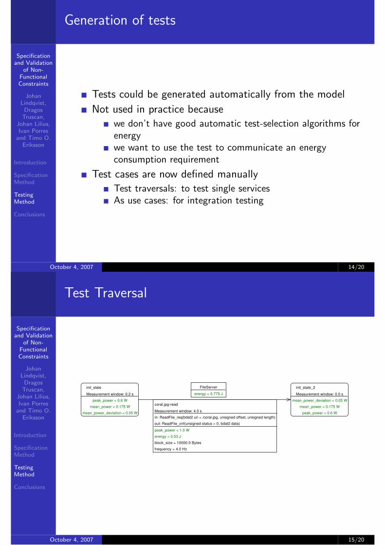
Test Traversal
init_state_2Measurement window: 0.0 s
mean_power_deviation < 0.05 Wmean_power < 0.175 W
peak_power < 0.6 W
FileServerenergy < 0.775 J
init_stateMeasurement window: 0.2 s
peak_power < 0.6 Wmean_power < 0.175 W
mean_power_deviation < 0.05 W
coral.jpg-readMeasurement window: 4.0 sin: ReadFile_req(bdat2 uri = /coral.jpg, unsigned offset, unsigned length)out: ReadFile_cnf(unsigned status = 0, bdat2 data)peak_power < 1.0 Wenergy < 0.53 Jblock_size = 10000.0 Bytesfrequency = 4.0 Hz
October 4, 2007 15/20

Specificationand Validation
of Non-FunctionalConstraints
JohanLindqvist,
DragosTruscan,
Johan Lilius,Ivan Porres
and Timo O.Eriksson
Introduction
SpecificationMethod
TestingMethod
Conclusions
Test setup
Standard shunt-resistor circuit ([FN01, JPEW02, FFB+00])
!!"#
"$%&
'(
"!
"
I
+
Us
U
The scope measures Us . Uemf is a high-quality powersupply. Now because U = Uemf − Us we have that
P = UI = (Uemf − Us)(Us/Rs)
October 4, 2007 16/20
Specificationand Validation
of Non-FunctionalConstraints
JohanLindqvist,
DragosTruscan,
Johan Lilius,Ivan Porres
and Timo O.Eriksson
Introduction
SpecificationMethod
TestingMethod
Conclusions
Test setup (cont’d)
Challenge: synchronization of measurement values withmodel.
October 4, 2007 17/20

Specificationand Validation
of Non-FunctionalConstraints
JohanLindqvist,
DragosTruscan,
Johan Lilius,Ivan Porres
and Timo O.Eriksson
Introduction
SpecificationMethod
TestingMethod
Conclusions
Result presentation
The measurements are mapped back onto the testrepresented as a “traversal path”.
October 4, 2007 18/20
Specificationand Validation
of Non-FunctionalConstraints
JohanLindqvist,
DragosTruscan,
Johan Lilius,Ivan Porres
and Timo O.Eriksson
Introduction
SpecificationMethod
TestingMethod
Conclusions
Conclusions
We have developed a specification method together with atesting setup
Partial specifications needed to leave freedom forimplementation
The approach allows for “quick” validation of energy andtiming constraints
It is being introduced into the production process at Nokia
October 4, 2007 19/20

Specificationand Validation
of Non-FunctionalConstraints
JohanLindqvist,
DragosTruscan,
Johan Lilius,Ivan Porres
and Timo O.Eriksson
Introduction
SpecificationMethod
TestingMethod
Conclusions
Future Work
Now we have concentrated on tests a vehicle forcommunication
How would you apply automated test generation methods?
Proper evaluation: how cost-effective is the approach?
Was it easier to communicate? Where the products better?
Abstract models of services to be used for partialverification.
Generalise the approach: the NoTA L IN and H INprotocols act as “adapters”. By replacing them we can usethe approach for non-NoTa systems.
October 4, 2007 20/20
Specificationand Validation
of Non-FunctionalConstraints
JohanLindqvist,
DragosTruscan,
Johan Lilius,Ivan Porres
and Timo O.Eriksson
Introduction
SpecificationMethod
TestingMethod
Conclusions
Keith I. Farkas, Jason Flinn, Godmar Back, Dirk Grunwald,and Jennifer M. Anderson.Quantifying the energy consumption of a pocket computerand a java virtual machine.SIGMETRICS Perform. Eval. Rev., 28(1):252–263, 2000.
Laura Marie Feeney and Martin Nilsson.Investigating the energy consumption of a wireless networkinterface in an ad hoc networking environment.In IEEE INFOCOM, 2001.
Brian Burns Jean-Pierre Ebert and Adam Wolisz.A trace-based approach for determining the energyconsumption of a WLAN network interface.In Proc. of European Wireless, pages 230–236, February2002.
October 4, 2007 20/20

Specificationand Validation
of Non-FunctionalConstraints
JohanLindqvist,
DragosTruscan,
Johan Lilius,Ivan Porres
and Timo O.Eriksson
Introduction
SpecificationMethod
TestingMethod
Conclusions
Ian Oliver Klaus Kronlof, Samu Kontinen and TimoEriksson.A Method for Mobile Terminal Platform ArchitectureDevelopment.In Proceedings of Forum on Design Languages 2006,Darmstadt, Germany, 2006.
Risto Suoranta.New Directions in Mobile Device Architectures.In Proceedings of the 9th Euromicro Conference on DigitalSystem Design (DSD’06), 2006.
October 4, 2007 20/20