SPECIFICATION & DESIGN MANUAL Wedge-Bolt
17
Wedge-Bolt ® Powers USA: (800) 524-3244 or (914) 235-6300 Canada: (905) 673-7295 or (514) 631-4216 www.powers.com 67 SPECIFICATION & DESIGN MANUAL SECTION CONTENTS Page No. General Information.................... 67 Installation Specifications .......... 68 Material Specifications ............... 69 Performance Data ........................ 70 Design Criteria ............................. 79 Ordering Information .................. 82 Carbon Steel Wedge-Bolt 410 Stainless Steel Wedge-Bolt Carbon Steel Wedge-Bolt OT (ANSI) HEAD STYLES Hex Head ANCHOR MATERIALS Zinc Plated Carbon Steel Mechanically Galvanized Carbon Steel Type 410 Stainless Steel ANCHOR SIZE RANGE (TYP.) 1/4" diameter x 1 1/4" length to 5/8" x 14" and 3/4" diameter x 8" lengths SUITABLE BASE MATERIALS Normal-Weight Concrete Structural Lightweight Concrete Grouted Concrete Masonry Brick Masonry Wedge-Bolt ® Screw Anchor PRODUCT DESCRIPTION The Wedge-Bolt anchor is a one piece, heavy duty screw anchor with a finished hex head. It is easy to identify, fully removable and vibration resistant. The Wedge-Bolt has many unique features and benefits that make it well suited for many applications in a variety of base materials. Optimum performance is obtained using a combination of patented design concepts. The steel threads along the anchor body self tap into the hole during installation and provide positive keyed engagement. The benefit to the designer is higher load capacities, while the benefit to the user is ease of installation. The Wedge-Bolt can be easily installed with either a powered impact wrench or conventional hand socket. Wedge-Bolt – Wedge-Bolt screw anchors are designed to be used with a matched tolerance Wedge-Bit TM for optimum performance. The Wedge-Bolt works in fixture clearance holes that are 1/16" over nominal, which is typical of standard fixture holes used in steel fabrication. Wedge-Bolt OT – The Wedge-Bolt OT is specifically engineered for use in fixture clearance holes sized a minimum of 1/8" over nominal. The Wedge-Bolt OT must be installed with an ANSI rotary drill bit. GENERAL APPLICATIONS AND USES • Racking and Shelving • Material Handling • Support Ledgers • Structural Anchorage • Fencing • Masonry Applications • Maintenance • Food and Beverage Facilities • Repairs • Retrofits FEATURES AND BENEFITS • One-piece design eliminates possibility of lost anchor parts or improper assembly • Tested in accordance with ASTM E488 and AC106 criteria • Qualified for seismic and wind loads • Wedge-Bolt anchor will fit standard fixture hole dimensions in fabricated steel • Can be installed with an impact wrench or conventional hand socket • Fast installation and immediate loading minimizes downtime • High load capacities and full grip along thread length • Diameter and length ID stamped on head of each hex head anchor for easy inspection • Finished hex head provides attractive appearance and eliminates tripping hazard • No expansion forces transferred to the base material • Can be installed closer to the edge than traditional expansion anchors • Versatile installation in concrete, block and brick masonry • Ratchet teeth on underside of hex washer head lock against the fixture • Removable and will not leave components in the hole APPROVALS AND LISTINGS International Code Council, Evaluation Service (ICC-ES) ESR-1678 (formerly listed in ER-5788) Southern Building Code Conference International (SBCCI) #2124 City of Los Angeles (COLA) Research Report LARR-25415 Florida Building Code Approval – FL2209.10 Miami-Dade County Notice of Acceptance (NOA) 00-0229.04 Federal GSA Specification – Meets the proof load requirements of FF-S-325C, Group II, Type 4, Class 1 (superseded) and CID A-A1923A, Type 4 Various North American Departments of Transportation (DOT) – See www.powers.com GUIDE SPECIFICATIONS CSI Divisions: 03151-Concrete Anchoring, 04081-Masonry Anchorage and 05090-Metal Fastenings. Screw Anchors shall be Wedge-Bolt or Wedge-Bolt OT anchors as supplied by Powers Fasteners, Inc., Brewster, NY.
Transcript of SPECIFICATION & DESIGN MANUAL Wedge-Bolt
Wedge-Bolt®
Powers USA: (800) 524-3244 or (914) 235-6300 Canada: (905) 673-7295 or (514) 631-4216 www.powers.com 67
AD
HES
IVES
MEC
HA
NIC
AL
AN
CH
OR
S
WA
LL
AN
CH
OR
S
POW
DER
AC
TUA
TED
GA
S FA
STEN
ING
RO
OFI
NG
FA
STEN
ERS
CA
RB
IDE
DR
ILL
BIT
S
SPECIFICATION & DESIGN MANUAL
SECTION CONTENTS Page No.
General Information.................... 67
Installation Specifications .......... 68
Material Specifications ............... 69
Performance Data........................ 70
Design Criteria ............................. 79
Ordering Information .................. 82
Carbon Steel Wedge-Bolt
410 Stainless Steel Wedge-Bolt
Carbon Steel Wedge-Bolt OT (ANSI)
HEAD STYLES
Hex Head
ANCHOR MATERIALS
Zinc Plated Carbon SteelMechanically Galvanized Carbon SteelType 410 Stainless Steel
ANCHOR SIZE RANGE (TYP.)
1/4" diameter x 1 1/4" length to 5/8" x 14" and3/4" diameter x 8" lengths
SUITABLE BASE MATERIALS
Normal-Weight ConcreteStructural Lightweight ConcreteGrouted Concrete MasonryBrick Masonry
Wedge-Bolt®
Screw Anchor
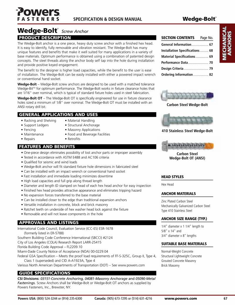
PRODUCT DESCRIPTIONThe Wedge-Bolt anchor is a one piece, heavy duty screw anchor with a finished hex head.It is easy to identify, fully removable and vibration resistant. The Wedge-Bolt has manyunique features and benefits that make it well suited for many applications in a variety ofbase materials. Optimum performance is obtained using a combination of patented designconcepts. The steel threads along the anchor body self tap into the hole during installationand provide positive keyed engagement.
The benefit to the designer is higher load capacities, while the benefit to the user is ease of installation. The Wedge-Bolt can be easily installed with either a powered impact wrenchor conventional hand socket.
Wedge-Bolt – Wedge-Bolt screw anchors are designed to be used with a matched toleranceWedge-BitTM for optimum performance. The Wedge-Bolt works in fixture clearance holes thatare 1/16" over nominal, which is typical of standard fixture holes used in steel fabrication.
Wedge-Bolt OT – The Wedge-Bolt OT is specifically engineered for use in fixture clearanceholes sized a minimum of 1/8" over nominal. The Wedge-Bolt OT must be installed with anANSI rotary drill bit.
GENERAL APPLICATIONS AND USES• Racking and Shelving • Material Handling• Support Ledgers • Structural Anchorage• Fencing • Masonry Applications• Maintenance • Food and Beverage Facilities• Repairs • Retrofits
FEATURES AND BENEFITS• One-piece design eliminates possibility of lost anchor parts or improper assembly• Tested in accordance with ASTM E488 and AC106 criteria• Qualified for seismic and wind loads• Wedge-Bolt anchor will fit standard fixture hole dimensions in fabricated steel• Can be installed with an impact wrench or conventional hand socket• Fast installation and immediate loading minimizes downtime• High load capacities and full grip along thread length• Diameter and length ID stamped on head of each hex head anchor for easy inspection• Finished hex head provides attractive appearance and eliminates tripping hazard• No expansion forces transferred to the base material• Can be installed closer to the edge than traditional expansion anchors• Versatile installation in concrete, block and brick masonry• Ratchet teeth on underside of hex washer head lock against the fixture• Removable and will not leave components in the hole
APPROVALS AND LISTINGSInternational Code Council, Evaluation Service (ICC-ES) ESR-1678
(formerly listed in ER-5788)Southern Building Code Conference International (SBCCI) #2124City of Los Angeles (COLA) Research Report LARR-25415Florida Building Code Approval – FL2209.10Miami-Dade County Notice of Acceptance (NOA) 00-0229.04Federal GSA Specification – Meets the proof load requirements of FF-S-325C, Group II, Type 4,
Class 1 (superseded) and CID A-A1923A, Type 4Various North American Departments of Transportation (DOT) – See www.powers.com
GUIDE SPECIFICATIONSCSI Divisions: 03151-Concrete Anchoring, 04081-Masonry Anchorage and 05090-MetalFastenings. Screw Anchors shall be Wedge-Bolt or Wedge-Bolt OT anchors as supplied byPowers Fasteners, Inc., Brewster, NY.
AD
HESIV
ES
MEC
HA
NIC
AL
AN
CH
OR
S
WA
LL A
NC
HO
RS
POW
DER
AC
TUA
TED
GA
S FA
STENIN
G
RO
OFIN
G
FASTEN
ERS
CA
RB
IDE
DR
ILL BITS
SPECIFICATION & DESIGN MANUAL Wedge-Bolt®
www.powers.com Canada: (905) 673-7295 or (514) 631-4216 Powers USA: (800) 524-3244 or (914) 235-6300 68
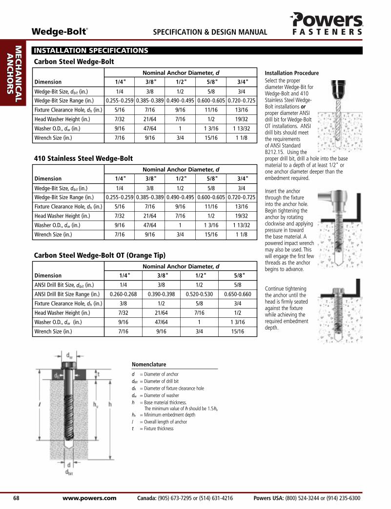
Select the properdiameter Wedge-Bit forWedge-Bolt and 410Stainless Steel Wedge-Bolt installations orproper diameter ANSIdrill bit for Wedge-BoltOT installations. ANSIdrill bits should meet the requirements of ANSI Standard B212.15. Using theproper drill bit, drill a hole into the basematerial to a depth of at least 1/2" or one anchor diameter deeper than theembedment required.
Insert the anchor through the fixture into the anchor hole.Begin tightening the anchor by rotating clockwise and applyingpressure in toward the base material. Apowered impact wrenchmay also be used. Thiswill engage the first few threads as the anchor begins to advance.
Continue tightening the anchor until the head is firmly seated against the fixture while achieving the required embedment depth.
Dimension 1/4" 3/8" 1/2" 5/8" 3/4"
Wedge-Bit Size, dbit (in.) 1/4 3/8 1/2 5/8 3/4
Wedge-Bit Size Range (in.) 0.255-0.259 0.385-0.389 0.490-0.495 0.600-0.605 0.720-0.725
Fixture Clearance Hole, dh (in.) 5/16 7/16 9/16 11/16 13/16
Head Washer Height (in.) 7/32 21/64 7/16 1/2 19/32
Washer O.D., dw (in.) 9/16 47/64 1 1 3/16 1 13/32
Wrench Size (in.) 7/16 9/16 3/4 15/16 1 1/8
Nominal Anchor Diameter, d
INSTALLATION SPECIFICATIONS
Carbon Steel Wedge-Bolt
Nomenclature
d = Diameter of anchordbit = Diameter of drill bitdh = Diameter of fixture clearance holedw = Diameter of washerh = Base material thickness.
The minimum value of h should be 1.5hv
hv = Minimum embedment depthl = Overall length of anchort = Fixture thickness
Installation Procedure
410 Stainless Steel Wedge-Bolt
Dimension 1/4" 3/8" 1/2" 5/8"
ANSI Drill Bit Size, dbit (in.) 1/4 3/8 1/2 5/8
ANSI Drill Bit Size Range (in.) 0.260-0.268 0.390-0.398 0.520-0.530 0.650-0.660
Fixture Clearance Hole, dh (in.) 3/8 1/2 5/8 3/4
Head Washer Height (in.) 7/32 21/64 7/16 1/2
Washer O.D., dw (in.) 9/16 47/64 1 1 3/16
Wrench Size (in.) 7/16 9/16 3/4 15/16
Nominal Anchor Diameter, d
Carbon Steel Wedge-Bolt OT (Orange Tip)
Wedge-Bolt®
Powers USA: (800) 524-3244 or (914) 235-6300 Canada: (905) 673-7295 or (514) 631-4216 www.powers.com 69
AD
HES
IVES
MEC
HA
NIC
AL
AN
CH
OR
S
WA
LL
AN
CH
OR
S
POW
DER
AC
TUA
TED
GA
S FA
STEN
ING
RO
OFI
NG
FA
STEN
ERS
CA
RB
IDE
DR
ILL
BIT
S
SPECIFICATION & DESIGN MANUAL
MATERIAL SPECIFICATIONS
Anchor Component Component Material
Anchor Body Case Hardened AISI 1020 / 1040 or 10B21 Carbon Steel
Zinc Plating ASTM B633, SC1, Type III (Fe/Zn 5)ASTM B695, Class 65, Type I (Mechanically galvanized Wedge-Bolts are available on request)
INSTALLATION SPECIFICATIONS
Carbon Steel Wedge-Bolt and Wedge-Bolt OT
Anchor Component Component Material
Anchor Body Type 410 Stainless Steel
Coating Class 4 Sealcoat (Passivated)
410 Stainless Steel Wedge-Bolt
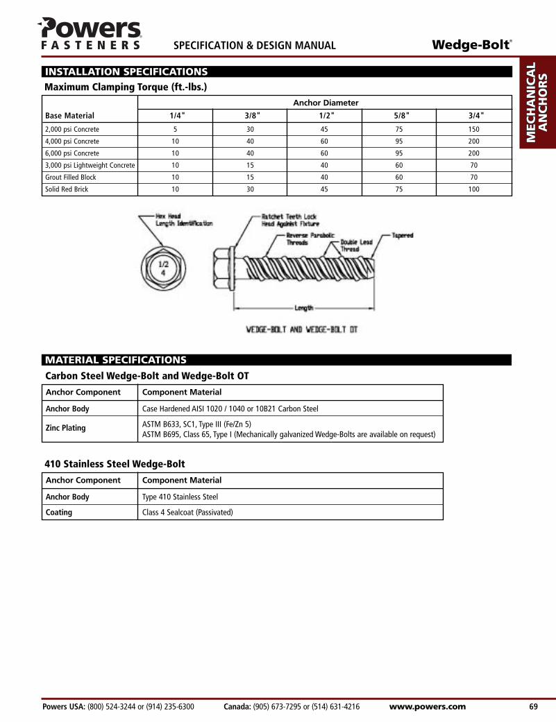
Base Material 1/4" 3/8" 1/2" 5/8" 3/4"
2,000 psi Concrete 5 30 45 75 150
4,000 psi Concrete 10 40 60 95 200
6,000 psi Concrete 10 40 60 95 200
3,000 psi Lightweight Concrete 10 15 40 60 70
Grout Filled Block 10 15 40 60 70
Solid Red Brick 10 30 45 75 100
Anchor Diameter
Maximum Clamping Torque (ft.-lbs.)
AD
HESIV
ES
MEC
HA
NIC
AL
AN
CH
OR
S
WA
LL A
NC
HO
RS
POW
DER
AC
TUA
TED
GA
S FA
STENIN
G
RO
OFIN
G
FASTEN
ERS
CA
RB
IDE
DR
ILL BITS
SPECIFICATION & DESIGN MANUAL Wedge-Bolt®
www.powers.com Canada: (905) 673-7295 or (514) 631-4216 Powers USA: (800) 524-3244 or (914) 235-6300 70
1(25.4)1 1/2(38.1)
2(50.8)2 1/2(63.5)1 1/2(38.1)
2(50.8)2 1/2(63.5)
3(76.2)3 1/2(88.9)
2(50.8)2 1/2(63.5)
3(76.2)3 1/2(88.9)
4(101.6)2 1/2(63.5)
3(76.2)3 1/2(88.9)
4(101.6)4 1/2
(114.3)5
(127.0)3
(76.2)3 1/2(88.9)
4(101.6)4 1/2
(114.3)5
(127.0)5 1/2
(139.7)6
(152.4)
1/4(6.4)
3/8(9.5)
1/2(12.7)
5/8(15.9)
3/4(19.1)
720 1,040 1,340 2,080 1,660 2,400(3.2) (4.7) (6.0) (9.4) (7.5) (10.8)1,440 2,200 2,140 2,200 2,480 2,500(6.5) (9.9) (9.6) (9.9) (11.2) (11.3)2,400 2,200 3,940 2,200 4,980 2,920(10.8) (9.9) (17.7) (9.9) (22.4) (13.1)3,520 2,200 4,660 2,200 5,260 2,920(15.8) (9.9) (21.0) (9.9) (23.7) (13.1)1,900 3,380 2,520 4,680 3,040 6,840(8.6) (15.2) (11.3) (21.1) (13.7) (30.8)3,000 4,440 3,920 5,080 5,200 6,840(13.5) (20.0) (17.6) (22.9) (23.4) (30.8)4,100 5,480 5,320 5,480 7,340 6,840(18.5) (24.7) (23.9) (24.7) (33.0) (30.8)5,800 5,700 7,740 5,920 9,900 6,840(26.1) (25.7) (34.8) (26.6) (44.6) (30.8)7,500 5,900 10,140 6,360 12,440 6,840(33.8) (26.6) (45.6) (28.6) (56.0) (30.8)2,860 5,720 3,940 6,820 4,780 8,740(12.9) (25.7) (17.7) (30.7) (21.5) (39.3)4,100 6,680 5,200 7,500 6,480 9,080(18.5) (30.1) (23.4) (33.8) (29.2) (40.9)5,920 7,160 7,800 8,380 9,380 9,080(26.6) (32.2) (35.1) (37.7) (42.2) (40.9)6,060 8,660 8,480 9,080 11,900 9,600(27.3) (39.0) (38.2) (40.9) (53.6) (43.2)7,560 8,660 12,620 9,080 12,620 9,600(34.0) (39.0) (56.8) (40.9) (56.8) (43.2)3,420 7,200 4,720 10,820 6,900 13,400(15.4) (32.4) (21.2) (48.7) (31.1) (60.3)4,560 9,300 7,380 12,220 8,960 14,200(20.5) (41.9) (33.2) (55.0) (40.3) (63.9)5,720 11,380 10,040 13,600 11,040 15,000(25.7) (51.2) (45.2) (61.2) (49.7) (67.5)8,240 12,580 12,760 14,760 14,320 15,920(37.1) (56.6) (57.4) (66.4) (64.4) (71.6)10,780 13,800 15,500 15,920 17,600 16,840(48.5) (62.1) (69.8) (71.6) (79.2) (75.8)13,300 15,000 18,220 17,080 20,860 17,760(59.9) (67.5) (82.0) (76.9) (93.9) (79.9)4,320 12,020 6,480 15,340 8,700 18,780(19.4) (54.1) (29.2) (69.0) (39.2) (84.5)5,720 13,280 9,320 18,780 11,360 20,800(25.7) (59.8) (41.9) (84.5) (51.1) (93.6)7,120 14,520 12,140 22,200 14,020 22,820(32.0) (65.3) (54.6) (99.9) (63.1) (102.7)9,240 16,640 13,580 23,320 16,720 23,800(41.6) (74.9) (61.1) (104.9) (75.2) (107.1)11,340 18,760 15,020 24,440 19,400 24,760(51.0) (84.4) (67.6) (110.0) (87.3) (111.4)13,440 20,880 16,460 25,560 22,080 25,720(60.5) (94.0) (74.1) (115.0) (99.4) (115.7)15,540 22,980 17,900 26,680 24,760 26,680(69.9) (103.4) (80.6) (120.1) (111.4) (120.1)
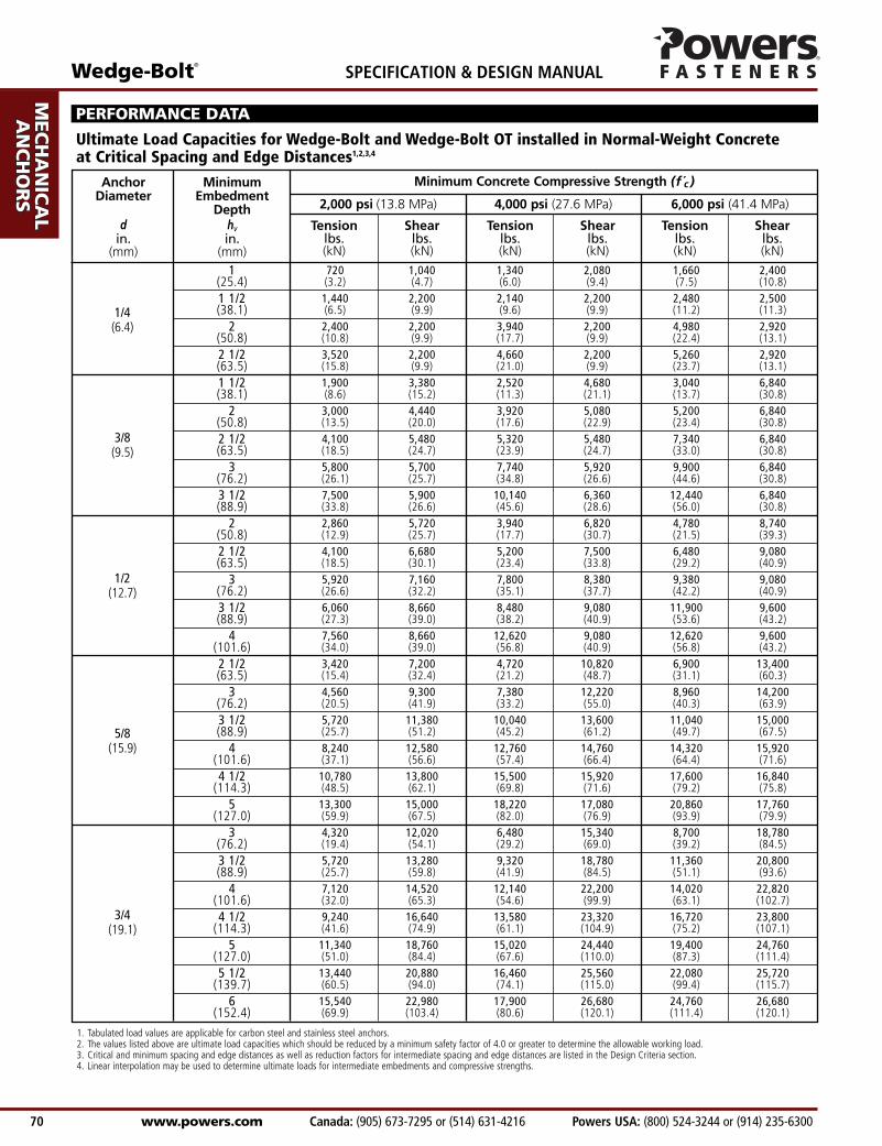
PERFORMANCE DATA
Ultimate Load Capacities for Wedge-Bolt and Wedge-Bolt OT installed in Normal-Weight Concrete at Critical Spacing and Edge Distances1,2,3,4
Minimum Concrete Compressive Strength (f c )
1. Tabulated load values are applicable for carbon steel and stainless steel anchors.2. The values listed above are ultimate load capacities which should be reduced by a minimum safety factor of 4.0 or greater to determine the allowable working load.3. Critical and minimum spacing and edge distances as well as reduction factors for intermediate spacing and edge distances are listed in the Design Criteria section.4. Linear interpolation may be used to determine ultimate loads for intermediate embedments and compressive strengths.
AnchorDiameter
din.
(mm)
MinimumEmbedment
Depthhvin.
(mm)
Tension Shear Tension Shear Tension Shearlbs. lbs. lbs. lbs. lbs. lbs.(kN) (kN) (kN) (kN) (kN) (kN)
2,000 psi (13.8 MPa) 4,000 psi (27.6 MPa) 6,000 psi (41.4 MPa)

Wedge-Bolt®
Powers USA: (800) 524-3244 or (914) 235-6300 Canada: (905) 673-7295 or (514) 631-4216 www.powers.com 71
AD
HES
IVES
MEC
HA
NIC
AL
AN
CH
OR
S
WA
LL
AN
CH
OR
S
POW
DER
AC
TUA
TED
GA
S FA
STEN
ING
RO
OFI
NG
FA
STEN
ERS
CA
RB
IDE
DR
ILL
BIT
S
SPECIFICATION & DESIGN MANUAL
1(25.4)1 1/2(38.1)
2(50.8)2 1/2(63.5)1 1/2(38.1)
2(50.8)2 1/2(63.5)
3(76.2)3 1/2(88.9)
2(50.8)2 1/2(63.5)
3(76.2)3 1/2(88.9)
4(101.6)2 1/2(63.5)
3(76.2)3 1/2(88.9)
4(101.6)4 1/2
(114.3)5
(127.0)3
(76.2)3 1/2(88.9)
4(101.6)4 1/2
(114.3)5
(127.0)5 1/2
(139.7)6
(152.4)
1/4(6.4)
3/8(9.5)
1/2(12.7)
5/8(15.9)
3/4(19.1)
180 260 335 520 415 600(0.8) (1.2) (1.5) (2.3) (1.9) (2.7)360 550 535 550 620 625(1.6) (2.5) (2.4) (2.5) (2.8) (2.8)600 550 985 550 1,245 730(2.7) (2.5) (4.4) (2.5) (5.6) (3.3)880 550 1,165 550 1,315 730(4.0) (2.5) (5.2) (2.5) (5.9) (3.3)475 845 630 1,170 760 1,710(2.1) (3.8) (2.8) (5.3) (3.4) (7.7)750 1,110 980 1,270 1,300 1,710(3.4) (5.0) (4.4) (5.7) (5.9) (7.7)1,025 1,370 1,330 1,370 1,835 1,710(4.6) (6.2) (6.0) (6.2) (8.3) (7.7)1,450 1,425 1,935 1,480 2,475 1,710(6.5) (6.4) (8.7) (6.7) (11.1) (7.7)1,875 1,475 2,535 1,590 3,110 1,710(8.4) (6.6) (11.4) (7.2) (14.0) (7.7)715 1,430 985 1,705 1,195 2,185(3.2) (6.4) (4.4) (7.7) (5.4) (9.8)1,025 1,670 1,300 1,875 1,620 2,270(4.6) (7.5) (5.9) (8.4) (7.3) (10.2)1,480 1,790 1,950 2,095 2,345 2,270(6.7) (8.1) (8.8) (9.4) (10.6) (10.2)1,515 2,165 2,120 2,270 2,975 2,400(6.8) (9.7) (9.5) (10.2) (13.4) (10.8)1,890 2,165 3,155 2,270 3,155 2,400(8.5) (9.7) (14.2) (10.2) (14.2) (10.8)855 1,800 1,180 2,705 1,725 3,350(3.8) (8.1) (5.3) (12.2) (7.8) (15.1)1,140 2,325 1,845 3,055 2,240 3,550(5.1) (10.5) (8.3) (13.7) (10.1) (16.0)1,430 2,845 2,510 3,400 2,760 3,750(6.4) (12.8) (11.3) (15.3) (12.4) (16.9)2,060 3,145 3,190 3,690 3,580 3,980(9.3) (14.2) (14.4) (16.6) (16.1) (17.9)2,695 3,450 3,875 3,980 4,400 4,210(12.1) (15.5) (17.4) (17.9) (19.8) (18.9)3,325 3,750 4,555 4,270 5,215 4,440(15.0) (16.9) (20.5) (19.2) (23.5) (20.0)1,080 3,005 1,620 3,835 2,175 4,695(4.9) (13.5) (7.3) (17.3) (9.8) (21.1)1,430 3,320 2,330 4,695 2,840 5,200(6.4) (14.9) (10.5) (21.1) (12.8) (23.4)1,780 3,630 3,035 5,550 3,505 5,705(8.0) (16.3) (13.7) (25.0) (15.8) (25.7)2,310 4,160 3,395 5,830 4,180 5,950(10.4) (18.7) (15.3) (26.2) (18.8) (26.8)2,835 4,690 3,755 6,110 4,850 6,190(12.8) (21.1) (16.9) (27.5) (21.8) (27.9)3,360 5,220 4,115 6,390 5,520 6,430(15.1) (23.5) (18.5) (28.8) (24.8) (28.9)3,885 5,745 4,475 6,670 6,190 6,670(17.5) (25.9) (20.1) (30.0) (27.9) (30.0)
PERFORMANCE DATA
Allowable Load Capacities for Wedge-Bolt and Wedge-Bolt OT installed in Normal-Weight Concrete at Critical Spacing and Edge Distances1,2,3,4,5
Minimum Concrete Compressive Strength (f c )
1. Tabulated load values are applicable for carbon steel and stainless steel anchors.2. Allowable load capacities listed are calculated using an applied safety factor of 4.0.3. Critical and minimum spacing and edge distances as well as reduction factors for intermediate spacing and edge distances are listed in the Design Criteria section.4. Linear interpolation may be used to determine allowable loads for intermediate embedments and compressive strengths.5. Allowable loads for anchors to resist short-term loads such as earthquake or wind may be increased by 33-1/3 percent for the duration of the load where permitted by code.
AnchorDiameter
din.
(mm)
MinimumEmbedment
Depthhvin.
(mm)
Tension Shear Tension Shear Tension Shearlbs. lbs. lbs. lbs. lbs. lbs.(kN) (kN) (kN) (kN) (kN) (kN)
2,000 psi (13.8 MPa) 4,000 psi (27.6 MPa) 6,000 psi (41.4 MPa)
AD
HESIV
ES
MEC
HA
NIC
AL
AN
CH
OR
S
WA
LL A
NC
HO
RS
POW
DER
AC
TUA
TED
GA
S FA
STENIN
G
RO
OFIN
G
FASTEN
ERS
CA
RB
IDE
DR
ILL BITS
SPECIFICATION & DESIGN MANUAL Wedge-Bolt®
www.powers.com Canada: (905) 673-7295 or (514) 631-4216 Powers USA: (800) 524-3244 or (914) 235-6300 72
1(25.4)1 1/2(38.1)
2(50.8)2 1/2(63.5)1 1/2(38.1)
2(50.8)2 1/2(63.5)
3(76.2)3 1/2(88.9)
2(50.8)2 1/2(63.5)
3(76.2)3 1/2(88.9)
4(101.6)2 1/2(63.5)
3(76.2)3 1/2(88.9)
4(101.6)4 1/2
(114.3)5
(127.0)3
(76.2)3 1/2(88.9)
4(101.6)4 1/2
(114.3)5
(127.0)5 1/2
(139.7)6
(152.4)
1/4(6.4)
3/8(9.5)
1/2(12.7)
5/8(15.9)
3/4(19.1)
4(101.6)
6(152.4)
8(203.2)
10(254.0)
12(304.8)
920 1,030 1,520 2,090 1,650 2,440(4.1) (4.6) (6.8) (9.4) (7.4) (11.0)1,760 2,580 2,360 2,780 2,480 2,690(7.9) (11.6) (10.6) (12.5) (11.2) (12.1)2,800 2,780 4,230 2,780 4,980 3,360(12.6) (12.5) (19.0) (12.5) (22.4) (15.1)4,220 3,080 4,900 3,080 5,260 3,660(19.0) (13.9) (22.1) (13.9) (23.7) (16.5)2,140 3,600 2,660 4,870 3,030 7,340(9.6) (16.2) (12.0) (21.9) (13.6) (33.0)3,300 4,540 4,120 5,180 5,185 7,340(14.9) (20.4) (18.5) (23.3) (23.3) (33.0)4,460 5,480 5,550 5,480 7,340 7,340(20.1) (24.7) (25.0) (24.7) (33.0) (33.0)6,180 6,400 7,970 6,460 9,890 7,475(27.8) (28.8) (35.9) (29.1) (44.5) (33.6)7,900 7,290 10,390 7,440 12,440 7,610(35.6) (32.8) (46.8) (33.5) (56.0) (34.2)2,960 6,570 3,930 7,420 4,780 9,000(13.3) (29.6) (17.7) (33.4) (21.5) (40.5)4,100 7,420 5,200 7,980 6,480 9,260(18.5) (33.4) (23.4) (35.9) (29.2) (41.7)5,910 7,700 7,800 8,730 9,380 9,260(26.6) (34.7) (35.1) (39.3) (42.2) (41.7)6,060 8,650 8,480 9,080 11,890 9,430(27.3) (38.9) (38.2) (40.9) (53.5) (42.4)7,620 8,650 13,260 9,080 13,260 9,600(34.3) (38.9) (59.7) (40.9) (59.7) (43.2)3,420 7,790 4,720 11,320 6,900 13,400(15.4) (35.1) (21.2) (50.9) (31.1) (60.3)4,560 10,075 7,380 12,740 8,960 13,620(20.5) (45.3) (33.2) (57.3) (40.3) (61.3)5,720 12,360 10,040 14,160 11,040 15,100(25.7) (55.6) (45.2) (63.7) (49.7) (68.0)8,280 13,700 12,760 15,400 14,320 15,920(37.3) (61.7) (57.4) (69.3) (64.4) (71.6)10,860 15,100 15,500 16,580 17,600 16,840(48.9) (68.0) (69.8) (74.6) (79.2) (75.8)13,440 16,480 18,220 17,750 20,860 17,750(60.5) (74.2) (82.0) (79.9) (93.9) (79.9)4,320 12,270 6,480 15,500 10,260 18,770(19.4) (55.2) (29.2) (69.8) (46.2) (84.5)5,760 13,945 9,320 19,160 12,140 20,795(25.9) (62.8) (41.9) (86.2) (54.6) (93.6)7,200 15,620 12,140 22,820 14,020 22,820(32.4) (70.3) (54.6) (102.7) (63.1) (102.7)9,800 18,740 13,640 24,760 16,720 25,160(44.1) (84.3) (61.4) (111.4) (75.2) (113.2)12,400 21,840 15,120 26,700 19,400 27,500(55.8) (98.3) (68.0) (120.2) (87.3) (123.8)15,000 24,940 16,600 28,640 22,080 29,840(67.5) (112.2) (74.7) (128.9) (99.4) (134.3)17,570 28,030 18,080 30,550 24,760 32,180(79.1) (126.1) (81.4) (137.5) (111.4) (144.8)
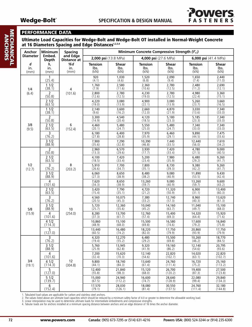
PERFORMANCE DATA
Ultimate Load Capacities for Wedge-Bolt and Wedge-Bolt OT installed in Normal-Weight Concrete at 16 Diameters Spacing and Edge Distances1,2,3,4
Minimum Concrete Compressive Strength (f c )
1. Tabulated load values are applicable for carbon and stainless steel anchors.2. The values listed above are ultimate load capacities which should be reduced by a minimum safety factor of 4.0 or greater to determine the allowable working load.3. Linear interpolation may be used to determine ultimate loads for intermediate embedments and compressive strengths.4. Tabular loads are for anchors installed at a minimum spacing distance between anchors and an edge distance of 16 times the anchor diameter.
Spacingand Edge
Distance at16 din.
(mm)
AnchorDiameter
din.
(mm)
MinimumEmbed.Depth
hvin.
(mm)
Tension Shear Tension Shear Tension Shearlbs. lbs. lbs. lbs. lbs. lbs.(kN) (kN) (kN) (kN) (kN) (kN)
2,000 psi (13.8 MPa) 4,000 psi (27.6 MPa) 6,000 psi (41.4 MPa)

Wedge-Bolt®
Powers USA: (800) 524-3244 or (914) 235-6300 Canada: (905) 673-7295 or (514) 631-4216 www.powers.com 73
AD
HES
IVES
MEC
HA
NIC
AL
AN
CH
OR
S
WA
LL
AN
CH
OR
S
POW
DER
AC
TUA
TED
GA
S FA
STEN
ING
RO
OFI
NG
FA
STEN
ERS
CA
RB
IDE
DR
ILL
BIT
S
SPECIFICATION & DESIGN MANUAL
1/4(6.4)
3/8(9.5)
1/2(12.7)
5/8(15.9)
3/4(19.1)
4(101.6)
6(152.4)
8(203.2)
10(254.0)
12(304.8)
1(25.4)1 1/2(38.1)
2(50.8)2 1/2(63.5)1 1/2(38.1)
2(50.8)2 1/2(63.5)
3(76.2)3 1/2(88.9)
2(50.8)2 1/2(63.5)
3(76.2)3 1/2(88.9)
4(101.6)2 1/2(63.5)
3(76.2)3 1/2(88.9)
4(101.6)4 1/2
(114.3)5
(127.0)3
(76.2)3 1/2(88.9)
4(101.6)4 1/2
(114.3)5
(127.0)5 1/2
(139.7)6
(152.4)
230 260 380 525 415 610(1.0) (1.2) (1.7) (2.4) (1.9) (2.7)440 645 590 695 620 675(2.0) (2.9) (2.7) (3.1) (2.8) (3.0)700 695 1,060 695 1,245 840(3.2) (3.1) (4.8) (3.1) (5.6) (3.8)1,055 770 1,225 770 1,315 915(4.7) (3.5) (5.5) (3.5) (5.9) (4.1)535 900 665 1,220 760 1,835(2.4) (4.1) (3.0) (5.5) (3.4) (8.3)825 1,135 1,030 1,295 1,300 1,835(3.7) (5.1) (4.6) (5.8) (5.9) (8.3)1,115 1,370 1,390 1,370 1,835 1,835(5.0) (6.2) (6.3) (6.2) (8.3) (8.3)1,545 1,600 1,995 1,615 2,475 1,870(7.0) (7.2) (9.0) (7.3) (11.1) (8.4)1,975 1,825 2,600 1,860 3,110 1,905(8.9) (8.2) (11.7) (8.4) (14.0) (8.6)740 1,645 985 1,855 1,195 2,250(3.3) (7.4) (4.4) (8.3) (5.4) (10.1)1,025 1,855 1,300 1,995 1,620 2,315(4.6) (8.3) (5.9) (9.0) (7.3) (10.4)1,480 1,925 1,950 2,185 2,345 2,315(6.7) (8.7) (8.8) (9.8) (10.6) (10.4)1,515 2,165 2,120 2,270 2,975 2,360(6.8) (9.7) (9.5) (10.2) (13.4) (10.6)1,905 2,165 3,315 2,270 3,315 2,400(8.6) (9.7) (14.9) (10.2) (14.9) (10.8)855 1,950 1,180 2,830 1,725 3,350(3.8) (8.8) (5.3) (12.7) (7.8) (15.1)1,140 2,520 1,845 3,185 2,240 3,405(5.1) (11.3) (8.3) (14.3) (10.1) (15.3)1,430 3,090 2,510 3,540 2,760 3,775(6.4) (13.9) (11.3) (15.9) (12.4) (17.0)2,070 3,425 3,190 3,850 3,580 3,980(9.3) (15.4) (14.4) (17.3) (16.1) (17.9)2,715 3,775 3,875 4,145 4,400 4,210(12.2) (17.0) (17.4) (18.7) (19.8) (18.9)3,360 4,120 4,555 4,440 5,215 4,440(15.1) (18.5) (20.5) (20.0) (23.5) (20.0)1,080 3,070 1,620 3,875 2,565 4,695(4.9) (13.8) (7.3) (17.4) (11.5) (21.1)1,440 3,490 2,330 4,790 3,035 5,200(6.5) (15.7) (10.5) (21.6) (13.7) (23.4)1,800 3,905 3,035 5,705 3,505 5,705(8.1) (17.6) (13.7) (25.7) (15.8) (25.7)2,450 4,685 3,410 6,190 4,180 6,290(11.0) (21.1) (15.3) (27.9) (18.8) (28.3)3,100 5,460 3,780 6,675 4,850 6,875(14.0) (24.5) (17.0) (30.0) (21.8) (30.9)3,750 6,235 4,150 7,160 5,520 7,460(16.9) (28.1) (18.7) (32.2) (24.8) (33.6)4,395 7,010 4,520 7,640 6,190 8,045(19.8) (31.5) (20.3) (34.4) (27.9) (36.2)
PERFORMANCE DATA
Allowable Load Capacities for Wedge-Bolt and Wedge-Bolt OT installed in Normal-Weight Concrete at 16 Diameters Spacing and Edge Distances1,2,3,4,5
Minimum Concrete Compressive Strength (f c )
1. Tabulated load values are applicable for carbon and stainless steel anchors.2. Allowable load capacities listed are calculated using an applied safety factor of 4.0.3. Linear interpolation may be used to determine allowable loads for intermediate embedments and compressive strengths.4. Allowable loads for anchors to resist short-term loads such as earthquake or wind may be increased by 33-1/3 percent for the duration of the load where permitted by code.5. Tabular loads are for anchors installed at a minimum spacing distance between anchors and an edge distance of 16 times the anchor diameter.
Spacingand Edge
Distance at16 din.
(mm)
AnchorDiameter
din.
(mm)
MinimumEmbed.Depth
hvin.
(mm)
Tension Shear Tension Shear Tension Shearlbs. lbs. lbs. lbs. lbs. lbs.(kN) (kN) (kN) (kN) (kN) (kN)
2,000 psi (13.8 MPa) 4,000 psi (27.6 MPa) 6,000 psi (41.4 MPa)

AD
HESIV
ES
MEC
HA
NIC
AL
AN
CH
OR
S
WA
LL A
NC
HO
RS
POW
DER
AC
TUA
TED
GA
S FA
STENIN
G
RO
OFIN
G
FASTEN
ERS
CA
RB
IDE
DR
ILL BITS
SPECIFICATION & DESIGN MANUAL Wedge-Bolt®
www.powers.com Canada: (905) 673-7295 or (514) 631-4216 Powers USA: (800) 524-3244 or (914) 235-6300 74
8 15,630 3,910 16,630 4,160 18,150 4,540(203.2) (70.3) (17.6) (74.8) (18.7) (81.7) (20.4)
9 16,995 4,250 18,185 4,545 19,820 4,955(228.6) (76.5) (19.1) (81.8) (20.5) (89.2) (22.3)
10 1 3/4 18,360 4,590 19,740 4,935 21,490 5,375(254.0) (44.5) (82.6) (20.7) (88.8) (22.2) (96.7) (24.2)
11 19,065 4,765 20,425 5,105 22,605 5,650(279.4) (85.8) (21.4) (91.9) (23.0) (101.7) (25.4)
12 19,775 4,945 21,105 5,275 23,715 5,930(304.8) (89.0) (22.3) (95.0) (23.7) (106.7) (26.7)
13 20,480 5,120 21,790 5,450 24,830 6,210(330.2) (92.2) (23.0) (98.1) (24.5) (111.7) (27.9)
1/2 3 3/8 1 3/4 5,020 1,255(12.7) (85.7) (44.5) (22.6) (5.6)
5/8 3 3/8 1 3/4 5,420 1,355(15.9) (85.7) (44.5) (24.4) (6.1)
3/4 3 3/8 1 3/4 5,660 1,415(19.1) (85.7) (44.5) (25.5) (6.4)
1. Tabulated load values are applicable to carbon steel and stainless steel anchors.2. Allowable load capacities are calculated using an applied safety factor of 4.0.3. Allowable loads for anchors to resist short-term loads such as earthquake or wind may be increased by 33-1/3 percent for the
duration of the load where permitted by code.
f c ≥ 2,000 psi (13.8 MPa)
Parallel to the Free EdgeMinimum
EdgeDistance
in.(mm)
AnchorDiameter
din.
(mm)
MinimumEmbedment
Depthhvin.
(mm)
PERFORMANCE DATA
AllowableShearlbs.(kN)
UltimateShearlbs.(kN)
Ultimate and Allowable Shear Load Capacities for Wedge-Bolt and Wedge-Bolt OT at the Edge of Normal-Weight Concrete1,2,3
Min.Embed.Depth
hvin.
(mm)
AnchorDia.
din.
(mm)
Min.Edge
Distance
in.(mm)
Ultimate Allow. Ultimate Allow. Ultimate Allow.lbs. lbs. lbs. lbs. lbs. lbs.(kN) (kN) (kN) (kN) (kN) (kN)
Minimum Concrete Compressive Strength (f c)
5/8(15.9)
Ultimate and Allowable Tension Load Capacities for Wedge-Bolt andWedge-Bolt OT Installed at the Edge of Normal-Weight Concrete1,2
1. Allowable load capacities are calculated using an applied safety factor of 4.0.2. Linear interpolation may be used to determine allowable loads for intermediate embedments and compressive strength.
1/2 4 1 3/4 1,270 1,425 470(12.7) (101.6) (44.5) (5.7) (6.4) (2.1)
2 1/2 610 1,155 380(63.5) (2.7) (5.2) (1.7)
5/8 3 3/4 1 3/4 1,310 1,330 490(15.9) (95.3) (44.5) (5.9) (6.0) (2.2)
5 2,015 1,505 600(127.0) (9.1) (6.8) (2.7)
1. Tabulated load values are applicable to carbon steel and stainless steel anchors.2. Allowable load capacities are calculated using an applied safety factor of 4.0.3. Allowable loads for anchors to resist short-term loads such as earthquake or wind may be increased by 33-1/3 percent for the
duration of the load where permitted by code.4. Allowable load capacities may also be applied to conditions at the edge of normal-weight concrete slabs.
f c ≥ 2,500 psi (17.2 MPa)
Parallel tothe Free
Edge
Towards theFree Edge
MinimumEdge
Distance
in.(mm)
Tensionlbs.(kN)
AnchorDiameter
din.
(mm)
MinimumEmbedment
Depthhvin.
(mm)
Shearlbs.(kN)
Shearlbs.(kN)
Allowable Load Capacities for Wedge-Bolt and Wedge-Bolt OTinstalled in Normal-Weight Concrete Stem Walls1,2,3,4
2,500 psi (17.2 MPa) 3,000 psi (20.7 MPa) 4,000 psi (27.6 MPa)

Wedge-Bolt®
Powers USA: (800) 524-3244 or (914) 235-6300 Canada: (905) 673-7295 or (514) 631-4216 www.powers.com 75
AD
HES
IVES
MEC
HA
NIC
AL
AN
CH
OR
S
WA
LL
AN
CH
OR
S
POW
DER
AC
TUA
TED
GA
S FA
STEN
ING
RO
OFI
NG
FA
STEN
ERS
CA
RB
IDE
DR
ILL
BIT
S
SPECIFICATION & DESIGN MANUAL
1/4(6.4)
3/8(9.5)
1/2(12.7)
5/8(15.9)
3/4(19.1)
2 3,320 3,000 830 750(50.8) (14.9) (13.5) (3.7) (3.4)
1 1/2 2,220 2,200 555 550(38.1) (10.0) (9.9) (2.5) (2.5)
2 1/4 3,760 3,960 940 990(57.2) (16.9) (17.8) (4.2) (4.5)
3 5,280 5,700 1,320 1,425(76.2) (23.8) (25.7) (5.9) (6.4)
2 2,920 6,180 730 1,545(50.8) (13.1) (27.8) (3.3) (7.0)
3 5,320 8,420 1,330 2,105(76.2) (23.9) (37.9) (6.0) (9.5)
4 7,720 10,660 1,930 2,665(101.6) (34.7) (48.0) (8.7) (12.0)
2 1/2 3,720 9,240 930 2,310(63.5) (16.7) (41.6) (4.2) (10.4)
3 3/4 7,940 14,440 1,985 3,610(95.3) (35.7) (65.0) (8.9) (16.2)
5 12,160 19,640 3,040 4,910(127.0) (54.7) (88.4) (13.7) (22.1)
5 1/4 13,320 22,520 3,330 5,630(133.4) (59.9) (101.3) (15.0) (25.3)
PERFORMANCE DATA
Ultimate and Allowable Load Capacities for Wedge-Bolt and Wedge-Bolt OT installed in Structural Lightweight Concrete1,2,3,4,5
MinimumEmbedment
Depthhvin.
(mm)
AnchorDiameter
din.
(mm)
Tension Shear Tension Shearlbs. lbs. lbs. lbs.(kN) (kN) (kN) (kN)
Ultimate Load Allowable Load
1. The values listed above are ultimate and allowable load capacities for anchors installed in sand-lightweight concrete.2. Allowable load capacities are calculated using an applied safety factor of 4.0.3. Critical and minimum spacing and edge distances as well as reduction factors for intermediate spacing and edge distances are listed in the Design Criteria section.4. Linear interpolation for allowable loads for anchors at intermediate embedment depths may also be used.5. Allowable loads for anchors to resist short-term loads such as earthquake or wind may be increased by 33-1/3 percent for the duration of the load where permitted by code.
Minimum Concrete Compressive Strength f c ≥ 3,000 psi (20.7 MPa)
2 2,660 3,600 665 900(50.8) (12.0) (16.2) (3.0) (4.1)
1 1/2 1,780 3,380 445 845(38.1) (8.0) (15.2) (2.0) (3.8)
2 1/4 3,160 4,320 790 1,080(57.2) (14.2) (19.4) (3.6) (4.9)
3 4,520 5,240 1,130 1,310(76.2) (20.3) (23.6) (5.1) (5.9)
2 2,940 4,380 735 1,095(50.8) (13.2) (19.7) (3.3) (4.9)
3 4,380 6,300 1,095 1,575(76.2) (19.7) (28.4) (4.9) (7.1)
4 5,820 8,220 1,455 2,055(101.6) (26.2) (37.0) (6.5) (9.2)
2 1/2 3,100 5,020 775 1,255(63.5) (14.0) (22.6) (3.5) (5.6)
3 3/4 5,420 7,640 1,355 1,910(95.3) (24.4) (34.4) (6.1) (8.6)
5 7,740 10,260 1,935 2,565(127.0) (34.8) (46.2) (8.7) (11.5)
5 1/4 9,700 11,540 2,425 2,885(133.4) (43.7) (51.9) (10.9) (13.0)
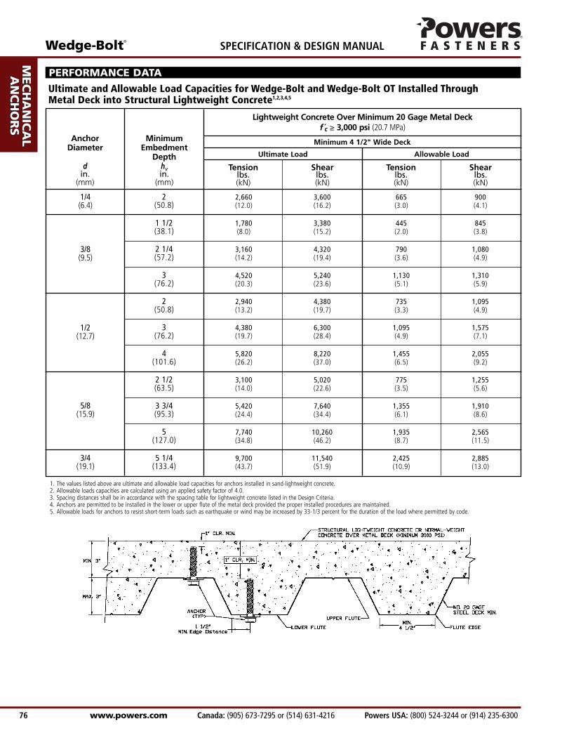
1/4(6.4)
3/8(9.5)
1/2(12.7)
5/8(15.9)
3/4(19.1)
MinimumEmbedment
Depthhvin.
(mm)
AnchorDiameter
din.
(mm)
Tension Shear Tension Shearlbs. lbs. lbs. lbs.(kN) (kN) (kN) (kN)
Ultimate Load
Minimum 4 1/2" Wide Deck
Allowable Load
1. The values listed above are ultimate and allowable load capacities for anchors installed in sand-lightweight concrete.2. Allowable loads capacities are calculated using an applied safety factor of 4.0.3. Spacing distances shall be in accordance with the spacing table for lightweight concrete listed in the Design Criteria.4. Anchors are permitted to be installed in the lower or upper flute of the metal deck provided the proper installed procedures are maintained.5. Allowable loads for anchors to resist short-term loads such as earthquake or wind may be increased by 33-1/3 percent for the duration of the load where permitted by code.
Lightweight Concrete Over Minimum 20 Gage Metal Deck f c ≥ 3,000 psi (20.7 MPa)
AD
HESIV
ES
MEC
HA
NIC
AL
AN
CH
OR
S
WA
LL A
NC
HO
RS
POW
DER
AC
TUA
TED
GA
S FA
STENIN
G
RO
OFIN
G
FASTEN
ERS
CA
RB
IDE
DR
ILL BITS
SPECIFICATION & DESIGN MANUAL Wedge-Bolt®
www.powers.com Canada: (905) 673-7295 or (514) 631-4216 Powers USA: (800) 524-3244 or (914) 235-6300 76
PERFORMANCE DATA
Ultimate and Allowable Load Capacities for Wedge-Bolt and Wedge-Bolt OT Installed Through Metal Deck into Structural Lightweight Concrete1,2,3,4,5
Anchor Installed Through Face Shell Into Grouted Cell
1(25.4)
2(50.8)1 1/2(38.1)1 1/2(38.1)2 1/2(63.5)2 1/2(63.5)3 1/2(88.9)
2(50.8)
3(76.2)
4(101.6)2 1/2(63.5)3 1/4(82.6)
4(101.6)
5(127.0)
3(76.2)
3(76.2)3 1/2(88.9)
4(101.6)
5(127.0)
Wedge-Bolt®
Powers USA: (800) 524-3244 or (914) 235-6300 Canada: (905) 673-7295 or (514) 631-4216 www.powers.com 77
AD
HES
IVES
MEC
HA
NIC
AL
AN
CH
OR
S
WA
LL
AN
CH
OR
S
POW
DER
AC
TUA
TED
GA
S FA
STEN
ING
RO
OFI
NG
FA
STEN
ERS
CA
RB
IDE
DR
ILL
BIT
S
SPECIFICATION & DESIGN MANUAL
1/4(6.4)
3/8(9.5)
1/2(12.7)
5/8(15.9)
3/4(19.1)
3 3/4(95.3)
12(304.8)
12(304.8)
12(304.8)
12(304.8)
150(0.7)340(1.5)
340(1.5)400(1.8)340(1.5)755(3.4)1,110(5.0)720(3.2)985(4.4)1,245(5.6)1,320(5.9)1,500(6.8)1,500(6.8)1,680(7.6)750(3.4)1,320(5.9)1,265(5.7)1,780(8.0)2,240(10.1)
80(0.4)340(1.5)
210(0.9)210(0.9)670(3.0)750(3.4)1,290(5.8)335(1.5)930(4.2)1,525(6.9)455(2.0)885(4.0)1,310(5.9)1,940(8.7)615(2.8)615(2.8)1,035(4.7)1,455(6.5)1,680(7.6)
3 3/4(95.3)3 3/4(95.3)
2(50.8)3 3/4(95.3)
2(50.8)7 7/8
(200.0)12
(304.8)
3 3/4(95.3)7 7/8
(200.0)12
(304.8)3 3/4(95.3)7 7/8
(200.0)12
(304.8)12
(304.8)3 3/4(95.3)
12(304.8)7 7/8
(200.0)12
(304.8)12
(304.8)
MinimumEmbed.Depth
hvin.
(mm)
RodDiameter
din.
(mm)
MinimumEnd
Distance
in.(mm)
MinimumEdge
Distance
in.(mm)
Tension Shear
lbs. lbs.(kN) (kN)
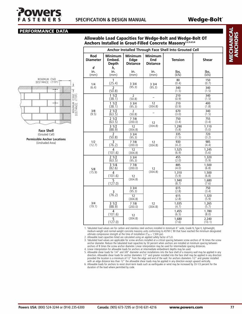
Allowable Load Capacities for Wedge-Bolt and Wedge-Bolt OTAnchors Installed in Grout-Filled Concrete Masonry1,2,3,4,5,6
PERFORMANCE DATA
Face Shell(Grouted Cell)
Permissible Anchor Locations(Unshaded Area)
3(76.2)
3 3/4(95.3)
12(304.8)
12(304.8)
1. Tabulated load values are for carbon and stainless steel anchors installed in minimum 6" wide, Grade N, Type II, lightweight,medium-weight and normal-weight concrete masonry units conforming to ASTM C 90 that have reached the minimum designated ultimate compressive strength at the time of installation (f’m ≥ 1,500 psi).
2. Allowable load capacities listed are calculated using an applied safety factor of 5.0.3. Tabulated load values are applicable for screw anchors installed at a critical spacing between screw anchors of 16 times the screw
anchor diameter. Reduce the tabulated load capacities by 50 percent when anchors are installed at minimum spacing between anchors of 8 times the screw anchor diameter. Linear interpolation may be used for intermediate spacing distances.
4. Linear interpolation for allowable loads for anchors at intermediate embedment depths may be used.5. Allowable shear loads for 1/4" and 3/8" diameter anchor installations into the face shell of a masonry wall may be applied in any
direction. Allowable shear loads for anchor diameters 1/2" and greater installed into the face shell may be applied in any direction provided the location is a minimum of 12" from the edge and end of the wall. For anchors diameters 1/2" and greater installed with an edge distance less than 12" the allowable shear loads may be applied in any direction except upward vertically.
6. Allowable loads for anchors to resist short-term loads such as earthquake or wind may be increased by 33-1/3 percent for the duration of the load where permitted by code.
–
–
12(304.8)
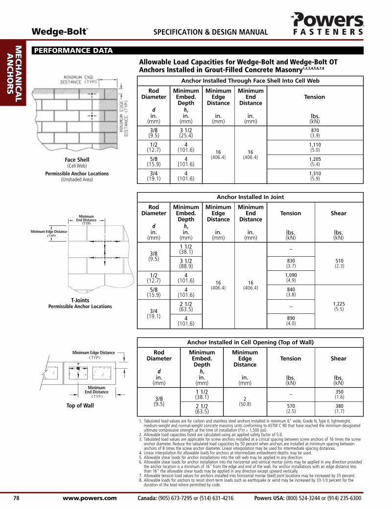
Anchor Installed in Cell Opening (Top of Wall)
Anchor Installed In Joint
AD
HESIV
ES
MEC
HA
NIC
AL
AN
CH
OR
S
WA
LL A
NC
HO
RS
POW
DER
AC
TUA
TED
GA
S FA
STENIN
G
RO
OFIN
G
FASTEN
ERS
CA
RB
IDE
DR
ILL BITS
SPECIFICATION & DESIGN MANUAL Wedge-Bolt®
www.powers.com Canada: (905) 673-7295 or (514) 631-4216 Powers USA: (800) 524-3244 or (914) 235-6300 78
16(406.4)
3/8(9.5)
1/2(12.7)
5/8(15.9)
3/4(19.1)
3 1/2(25.4)
4(101.6)
4(101.6)
4(101.6)
870(3.9)
1,110(5.0)
1,205(5.4)
1,310(5.9)
MinimumEmbed.Depth
hvin.
(mm)
RodDiameter
din.
(mm)
MinimumEnd
Distance
in.(mm)
MinimumEdge
Distance
in.(mm)
Tension
lbs.(kN)
Allowable Load Capacities for Wedge-Bolt and Wedge-Bolt OTAnchors Installed in Grout-Filled Concrete Masonry1,2,3,4,5,6,7,8
PERFORMANCE DATA
Face Shell(Cell Web)
Permissible Anchor Locations(Unshaded Area)
Anchor Installed Through Face Shell Into Cell Web
16(406.4)
16(406.4)
16(406.4)
3/8(9.5)
1/2(12.7)
1/2(12.7)
5/8(15.9)
3/8(9.5)
1/2(12.7
1 1/2(38.1)
3 1/2(88.9)
4(101.6)
4(101.6)
2 1/2(63.5)
4(101.6)
–
830(3.7)
1,090(4.9)
840(3.8)
–
890(4.0)
MinimumEmbed.Depth
hvin.
(mm)
RodDiameter
din.
(mm)
MinimumEnd
Distance
in.(mm)
MinimumEdge
Distance
in.(mm)
Tension Shear
lbs. lbs.(kN) (kN)
510(2.3)
1,225(5.5)
3/8(9.5)
3/4(19.1)
T-JointsPermissible Anchor Locations
Top of Wall2
(50.8)
1 1/2(38.1)
2 1/2(63.5)
–
570(2.5)
MinimumEmbed.Depth
hvin.
(mm)
RodDiameter
din.
(mm)
MinimumEdge
Distance
in.(mm)
Tension Shear
lbs. lbs.(kN) (kN)
350(1.6)
380(1.7)
3/8(9.5)
1. Tabulated load values are for carbon and stainless steel anchors installed in minimum 6" wide, Grade N, Type II, lightweight,medium-weight and normal-weight concrete masonry units conforming to ASTM C 90 that have reached the minimum designated ultimate compressive strength at the time of installation (f'm ≥ 1,500 psi).
2. Allowable load capacities listed are calculated using an applied safety factor of 5.0.3. Tabulated load values are applicable for screw anchors installed at a critical spacing between screw anchors of 16 times the screw
anchor diameter. Reduce the tabulated load capacities by 50 percent when anchors are installed at minimum spacing between anchors of 8 times the screw anchor diameter. Linear interpolation may be used for intermediate spacing distances.
4. Linear interpolation for allowable loads for anchors at intermediate embedment depths may be used.5. Allowable shear loads for anchor installations into the cell web may be applied in any direction.6. Allowable shear loads for anchor installation into the horizontal and vertical mortar joints may be applied in any direction provided
the anchor location is a minimum of 16" from the edge and end of the wall. For anchor installations with an edge distance less than 16" the allowable shear loads may be applied in any direction except upward vertically.
7. Allowable tension load values for anchors installed into horizontal mortar (bed) joint locations may be increased by 35 percent.8. Allowable loads for anchors to resist short-term loads such as earthquake or wind may be increased by 33-1/3 percent for the
duration of the load where permitted by code.

Wedge-Bolt®
Powers USA: (800) 524-3244 or (914) 235-6300 Canada: (905) 673-7295 or (514) 631-4216 www.powers.com 79
AD
HES
IVES
MEC
HA
NIC
AL
AN
CH
OR
S
WA
LL
AN
CH
OR
S
POW
DER
AC
TUA
TED
GA
S FA
STEN
ING
RO
OFI
NG
FA
STEN
ERS
CA
RB
IDE
DR
ILL
BIT
S
SPECIFICATION & DESIGN MANUAL
1/4(6.4)
3/8(9.5)
1/2(12.7)
5/8(15.9)
3/4(19.1)
2 1/2 4 4" 2,280 1,480 455 295(63.5) (101.6) Any Direction (10.3) (6.7) (2.0) (1.3)
3 1/2 6 6" 3,390 3,830 680 765(88.9) (152.4) Any Direction (15.3) (17.2) (3.1) (3.4)
4 8 8" 4,800 7,060 960 1,410(101.6) (101.6) Any Direction (21.6) (31.8) (4.3) (6.3)
4 10 12" 6,120 11,250 1,225 2,250(101.6) (254.0) Any Direction (27.5) (50.6) (5.5) (10.1)
4 12 6,580 12,340 1,315 2,470(101.6) (304.8) (29.6) (55.5) (5.9) (11.1)
MinimumEmbed.Depth
hvin.
(mm)
AnchorDiameter
din.
(mm)
MinimumSpacingDistance
MinimumEdge and
EndDistance
in.(mm)
Tension Shear Tension Shearlbs. lbs. lbs. lbs.(kN) (kN) (kN) (kN)
Ultimate Load Allowable Load
Structural Brick Masonryf m ≥ 1,500 psi (10.4 MPa)
1. Tabulated load values are applicable to carbon steel and stainless steel anchors.2. Tabulated load values are for anchors installed in minimum Grade SW multiple wythe, solid brick masonry conforming to ASTM C62.3. Allowable loads are calculated using an applied safety factor of 5.0.
Ultimate and Allowable Load Capacities for Wedge-Bolt and Wedge- Bolt OT Anchors Installed in Multiple Wythe Brick Masonry1,2,3
PERFORMANCE DATA
2 Bricks or 16"
Any Direction(whichever
is less)
Load Adjustment Factors for Spacing and Edge DistancesAnchor Installed in Normal-Weight Concrete
Anchor Critical Distance Critical Minimum Distance MinimumDimension Load Type (Full Anchor Capacity) Load Factor (Reduced Capacity) Load Factor
Spacing (s)Tension scr = 12d FN = 1.0 smin = 4d FN = 0.50
Shear scr = 12d FV = 1.0 smin = 4d FV = 0.75
Edge Distance (c)Tension ccr = 8d FN = 1.0 cmin = 3d FN = 0.70
Shear ccr = 12d FV = 1.0 cmin = 3d FV = 0.15
Anchor Installed in Lightweight Concrete
Anchor Critical Distance Critical Minimum Distance MinimumDimension Load Type (Full Anchor Capacity) Load Factor (Reduced Capacity) Load Factor
Spacing (s)Tension scr = 14.1d FN = 1.0 smin = 4.7d FN = 0.50
Shear scr = 14.1d FV = 1.0 smin = 4.7d FV = 0.75
Edge Distance (c)Tension ccr = 9.4d FN = 1.0 cmin = 3.5d FN = 0.70
Shear ccr = 14.1d FV = 1.0 cmin = 3.5d FV = 0.15
DESIGN CRITERIA
NuNn( ) Vu
Vn( )+53
53
≤ 1 NuNn( ) Vu
Vn( )+ ≤ 1
Combined Loading
For anchors loaded in both shear and tension, the combination of loads should be proportioned as follows:
Where: Nu = Applied Service Tension LoadNn = Allowable Tension LoadVu = Applied Service Shear LoadVn = Allowable Shear Load
OR

AD
HESIV
ES
MEC
HA
NIC
AL
AN
CH
OR
S
WA
LL A
NC
HO
RS
POW
DER
AC
TUA
TED
GA
S FA
STENIN
G
RO
OFIN
G
FASTEN
ERS
CA
RB
IDE
DR
ILL BITS
SPECIFICATION & DESIGN MANUAL Wedge-Bolt®
www.powers.com Canada: (905) 673-7295 or (514) 631-4216 Powers USA: (800) 524-3244 or (914) 235-6300 80
1 0.751 1/2 0.81 0.75
2 0.88 0.79 0.752 1/2 0.94 0.83 0.78 0.75
3 1.00 0.88 0.81 0.78 0.754 1/2 1.00 0.91 0.85 0.81
6 1.00 0.93 0.887 1/2 1.00 0.94
9 1.00
1 0.501 1/2 0.63 0.50
2 0.75 0.58 0.502 1/2 0.88 0.67 0.56 0.50
3 1.00 0.75 0.63 0.55 0.504 1/2 1.00 0.81 0.70 0.63
6 1.00 0.85 0.757 1/2 1.00 0.88
9 1.00
Spacing, Tension (FN)
Load Adjustment Factors for Normal-Weight Concrete
Notes: For anchors loaded in shear, the critical edgedistance (ccr ) is equal to 12 anchor diameters (12d )at which the anchor achieves 100% of load.Minimum edge distance (cmin) is equal to 3 anchordiameters (3d ) at which the anchor achieves 15%of load
DESIGN CRITERIA
Notes: For anchors loaded in tension, the criticaledge distance (ccr ) is equal to 8 anchor diameters(8d ) at which the anchor achieves 100% of load.Minimum edge distance (cmin) is equal to 3 anchordiameters (3d ) at which the anchor achieves 70% of load.
Notes: For anchors loaded in tension, the criticalspacing (scr ) is equal to 12 anchor diameters (12d )at which the anchor achieves 100% of load.Minimum spacing (smin ) is equal to 4 anchordiameters (4d ) at which the anchor achieves 50% of load.
Notes: For anchors loaded in shear, the criticalspacing (scr ) is equal to 12 anchor diameters (12d )at which the anchor achieves 100% of load.Minimum spacing (smin ) is equal to 4 anchordiameters (4d ) at which the anchor achieves 75% of load.
Dia. (in.) 1/4 3/8 1/2 5/8 3/4scr (in.) 3 4 1/2 6 7 1/2 9smin (in.) 1 1 1/2 2 2 1/2 3
Spac
ing,
s (in
ches
)
Spacing, Shear (FV)Dia. (in.) 1/4 3/8 1/2 5/8 3/4scr (in.) 3 4 1/2 6 7 1/2 9smin (in.) 1 1 1/2 2 2 1/2 3
Spac
ing,
s (in
ches
)
Edge Distance, Tension (FN)Dia. (in.) 1/4 3/8 1/2 5/8 3/4ccr (in.) 2 3 4 5 6cmin (in.) 3/4 1 1/8 1 1/2 1 7/8 2 1/4
Edge
Dis
tanc
e,c
(in.)
3/4 0.151 1/8 0.29 0.151 1/2 0.43 0.24 0.151 7/8 0.58 0.34 0.22 0.152 1/4 0.72 0.43 0.29 0.21 0.15
3 1.00 0.62 0.43 0.32 0.244 1/2 1.00 0.72 0.55 0.43
6 1.00 0.77 0.627 1/2 1.00 0.81
9 1.00
Edge Distance, Shear (FV)Dia. (in.) 1/4 3/8 1/2 5/8 3/4ccr (in.) 3 4 1/2 6 7 1/2 9cmin (in.) 3/4 1 1/8 1 1/2 1 7/8 2 1/4
Edge
Dis
tanc
e,c
(in.)
3/4 0.701 1/8 0.79 0.701 1/2 0.88 0.76 0.701 7/8 0.97 0.82 0.75 0.70
2 1.00 0.84 0.76 0.712 1/4 0.88 0.79 0.74 0.70
3 1.00 0.88 0.81 0.764 1.00 0.90 0.845 1.00 0.926 1.00
Edge Distance, Tension (FN)
Spacing, Tension (FN)
Spacing, Shear (FV)
Edge Distance, Shear (FV)
Wedge-Bolt®
Powers USA: (800) 524-3244 or (914) 235-6300 Canada: (905) 673-7295 or (514) 631-4216 www.powers.com 81
AD
HES
IVES
MEC
HA
NIC
AL
AN
CH
OR
S
WA
LL
AN
CH
OR
S
POW
DER
AC
TUA
TED
GA
S FA
STEN
ING
RO
OFI
NG
FA
STEN
ERS
CA
RB
IDE
DR
ILL
BIT
S
SPECIFICATION & DESIGN MANUAL
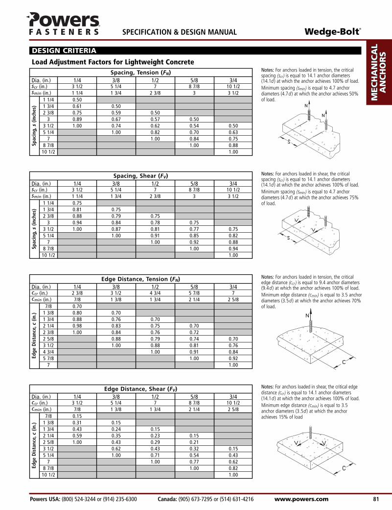
1 1/4 0.751 3/4 0.81 0.752 3/8 0.88 0.79 0.75
3 0.94 0.84 0.78 0.753 1/2 1.00 0.87 0.81 0.77 0.755 1/4 1.00 0.91 0.85 0.82
7 1.00 0.92 0.888 7/8 1.00 0.94
10 1/2 1.00
1 1/4 0.501 3/4 0.61 0.502 3/8 0.75 0.59 0.50
3 0.89 0.67 0.57 0.503 1/2 1.00 0.74 0.62 0.54 0.505 1/4 1.00 0.82 0.70 0.63
7 1.00 0.84 0.758 7/8 1.00 0.88
10 1/2 1.00
Load Adjustment Factors for Lightweight Concrete
Notes: For anchors loaded in shear, the critical edgedistance (ccr) is equal to 14.1 anchor diameters(14.1d ) at which the anchor achieves 100% of load.Minimum edge distance (cmin) is equal to 3.5anchor diameters (3.5d ) at which the anchorachieves 15% of load
DESIGN CRITERIA
Notes: For anchors loaded in tension, the criticaledge distance (ccr ) is equal to 9.4 anchor diameters(9.4d ) at which the anchor achieves 100% of load.Minimum edge distance (cmin) is equal to 3.5 anchordiameters (3.5d ) at which the anchor achieves 70% of load.
Notes: For anchors loaded in tension, the criticalspacing (scr) is equal to 14.1 anchor diameters(14.1d ) at which the anchor achieves 100% of load.Minimum spacing (smin) is equal to 4.7 anchordiameters (4.7d ) at which the anchor achieves 50% of load.
Notes: For anchors loaded in shear, the criticalspacing (scr) is equal to 14.1 anchor diameters(14.1d ) at which the anchor achieves 100% of load.Minimum spacing (smin) is equal to 4.7 anchordiameters (4.7d ) at which the anchor achieves 75% of load.
Dia. (in.) 1/4 3/8 1/2 5/8 3/4scr (in.) 3 1/2 5 1/4 7 8 7/8 10 1/2smin (in.) 1 1/4 1 3/4 2 3/8 3 3 1/2
Spac
ing,
s (in
ches
)
Dia. (in.) 1/4 3/8 1/2 5/8 3/4scr (in.) 3 1/2 5 1/4 7 8 7/8 10 1/2smin (in.) 1 1/4 1 3/4 2 3/8 3 3 1/2
Spac
ing,
s (in
ches
)
Dia. (in.) 1/4 3/8 1/2 5/8 3/4ccr (in.) 2 3/8 3 1/2 4 3/4 5 7/8 7cmin (in.) 7/8 1 3/8 1 3/4 2 1/4 2 5/8
Edge
Dis
tanc
e,c
(in.)
Dia. (in.) 1/4 3/8 1/2 5/8 3/4ccr (in.) 3 1/2 5 1/4 7 8 7/8 10 1/2cmin (in.) 7/8 1 3/8 1 3/4 2 1/4 2 5/8
Edge
Dis
tanc
e,c
(in.)
7/8 0.701 3/8 0.80 0.701 3/4 0.88 0.76 0.702 1/4 0.98 0.83 0.75 0.702 3/8 1.00 0.84 0.76 0.722 5/8 0.88 0.79 0.74 0.703 1/2 1.00 0.88 0.81 0.764 3/4 1.00 0.91 0.845 7/8 1.00 0.92
7 1.00
7/8 0.151 3/8 0.31 0.151 3/4 0.43 0.24 0.152 1/4 0.59 0.35 0.23 0.152 5/8 1.00 0.43 0.29 0.213 1/2 0.62 0.43 0.32 0.155 1/4 1.00 0.71 0.54 0.43
7 1.00 0.77 0.628 7/8 1.00 0.82
10 1/2 1.00

AD
HESIV
ES
MEC
HA
NIC
AL
AN
CH
OR
S
WA
LL A
NC
HO
RS
POW
DER
AC
TUA
TED
GA
S FA
STENIN
G
RO
OFIN
G
FASTEN
ERS
CA
RB
IDE
DR
ILL BITS
SPECIFICATION & DESIGN MANUAL Wedge-Bolt®
www.powers.com Canada: (905) 673-7295 or (514) 631-4216 Powers USA: (800) 524-3244 or (914) 235-6300 82
ORDERING INFORMATION
Catalog Wedge Bit Clearance Hole Minimum Thread Standard StandardNumber Size Diameter Diameter Embedment Length Box Carton
7204 1/4"x 1 1/4" 1/4" 5/16" 1" 1 1/8" 100 5007206 1/4"x 1 3/4" 1/4" 5/16" 1" 1 5/8" 100 5007208 1/4"x 2 1/4" 1/4" 5/16" 1" 2" 100 5007210 1/4"x 3" 1/4" 5/16" 1" 2 3/4" 100 5007220 3/8"x 1 3/4" 3/8" 7/16" 1 1/2" 1 1/2" 50 2507222 3/8"x 2 1/2" 3/8" 7/16" 1 1/2" 2 1/4" 50 2507224 3/8"x 3" 3/8" 7/16" 1 1/2" 2 3/4" 50 2507226 3/8"x 4" 3/8" 7/16" 1 1/2" 3 3/4" 50 2507228 3/8"x 5" 3/8" 7/16" 1 1/2" 3 3/4" 50 2507230 3/8"x 6" 3/8" 7/16" 1 1/2" 3 3/4" 50 1507240 1/2"x 2" 1/2" 9/16" 1 3/4" 2 1/4" 50 2007242 1/2"x 2 1/2" 1/2" 9/16" 1 3/4" 2 3/4" 50 2007244 1/2"x 3" 1/2" 9/16" 1 3/4" 2 3/4" 50 1507246 1/2"x 4" 1/2" 9/16" 1 3/4" 3 3/4" 50 1507248 1/2"x 5" 1/2" 9/16" 1 3/4" 3 3/4" 25 1007250 1/2"x 6" 1/2" 9/16" 1 3/4" 3 3/4" 25 757260 5/8"x 3" 5/8" 11/16" 2 1/2" 2 3/4" 25 1007262 5/8"x 4" 5/8" 11/16" 2 1/2" 3 3/4" 25 1007264 5/8"x 5" 5/8" 11/16" 2 1/2" 3 3/4" 25 757266 5/8"x 6" 5/8" 11/16" 2 1/2" 3 3/4" 25 757270 5/8"x 10" 5/8" 1 1/16" 2 1/2" 6" 25 757272 5/8"x 12" 5/8" 1 1/16" 2 1/2" 6" 25 757274 5/8"x 14" 5/8" 1 1/16" 2 1/2" 6" 25 –7280 3/4"x 3" 3/4" 13/16" 2 1/2" 2 3/4" 20 607282 3/4"x 4" 3/4" 13/16" 3" 3 3/4" 20 607284 3/4"x 5" 3/4" 13/16" 3" 3 3/4" 20 607286 3/4"x 6" 3/4" 13/16" 3" 3 3/4" 20 607288 3/4"x 8" 3/4" 13/16" 3" 3 3/4" 10 40
Carbon Steel Wedge-Bolt
Installation is recommended with the use of a Wedge-Bit.
Catalog Wedge Bit Clearance Hole Minimum Thread Standard StandardNumber Size Diameter Diameter Embedment Length Box Carton
7701 1/4"x 1 3/4" 1/4" 5/16" 1" 1 5/8" 100 5007705 3/8"x 2 1/2" 3/8" 7/16" 1 1/2" 2 1/4" 50 2507706 3/8"x 3" 3/8" 7/16" 1 1/2" 2 3/4" 50 2507710 1/2"x 3" 1/2" 9/16" 1 3/4" 2 3/4" 50 1507711 1/2"x 4" 1/2" 9/16" 1 3/4" 3 3/4" 50 1507715 5/8"x 4" 5/8" 11/16" 2 1/2" 3 3/4" 25 1007722 3/4"x 6" 3/4" 13/16" 3" 3 3/4" 20 60
410 Stainless Steel Wedge-Bolt
Installation is recommended with the use of a Wedge-Bit.
Catalog Drill Bit Clearance Hole Minimum Thread Standard StandardNumber Size Diameter Diameter Embedment Length Box Carton
7215 1/4"x 3" 1/4" 3/8" 1" 2 3/4" 100 5007216 3/8"x 4" 3/8" 1/2" 1 1/2" 3 3/4" 50 2507217 1/2"x 4" 1/2" 5/8" 1 3/4" 3 3/4" 50 1507218 1/2"x 5" 1/2" 5/8" 1 3/4" 3 3/4" 25 1007214 1/2"x 6" 1/2" 5/8" 1 3/4" 3 3/4" 25 757219 5/8"x 4" 5/8" 3/4" 2 1/2" 3 3/4" 25 1007221 5/8"x 5" 5/8" 3/4" 2 1/2" 3 3/4" 25 757227 5/8"x 6" 5/8" 3/4" 2 1/2" 3 3/4" 25 757229 5/8"x 7" 5/8" 3/4" 2 1/2" 3 3/4" 25 40
Carbon Steel Wedge-Bolt OT
Installation is recommended with the use of an ANSI bit.
Wedge-Bolt®
Powers USA: (800) 524-3244 or (914) 235-6300 Canada: (905) 673-7295 or (514) 631-4216 www.powers.com 83
AD
HES
IVES
MEC
HA
NIC
AL
AN
CH
OR
S
WA
LL
AN
CH
OR
S
POW
DER
AC
TUA
TED
GA
S FA
STEN
ING
RO
OFI
NG
FA
STEN
ERS
CA
RB
IDE
DR
ILL
BIT
S
SPECIFICATION & DESIGN MANUAL
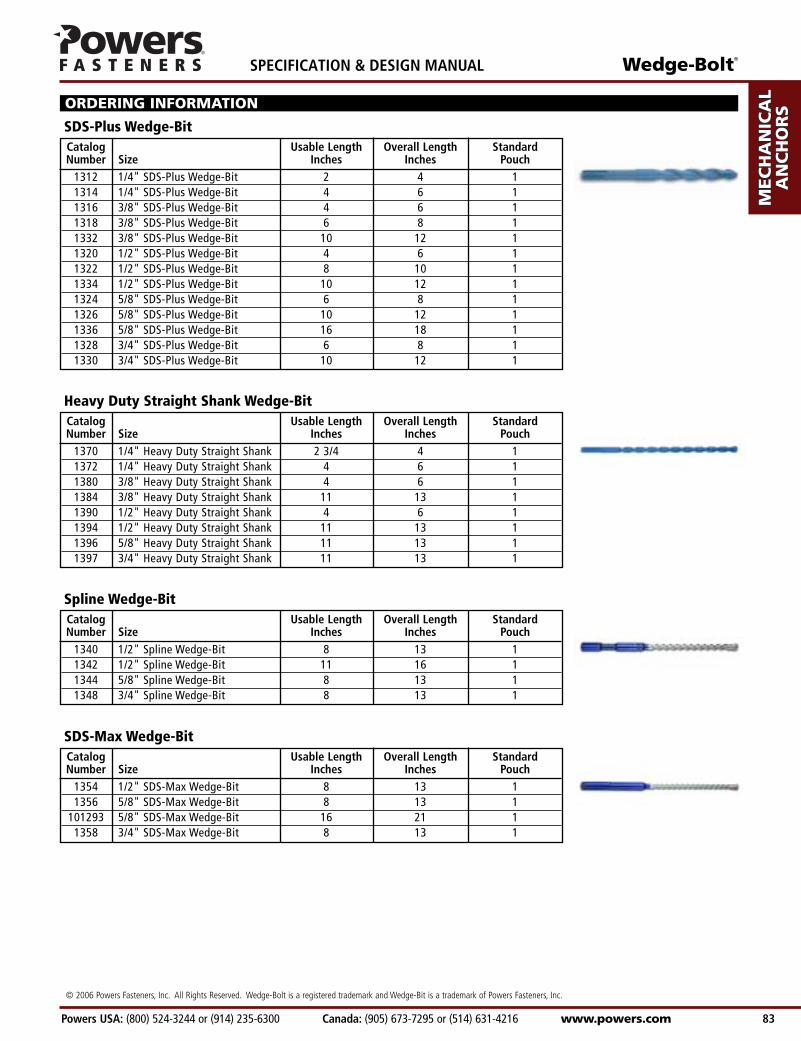
ORDERING INFORMATION
Catalog Usable Length Overall Length StandardNumber Size Inches Inches Pouch
1312 1/4" SDS-Plus Wedge-Bit 2 4 11314 1/4" SDS-Plus Wedge-Bit 4 6 11316 3/8" SDS-Plus Wedge-Bit 4 6 11318 3/8" SDS-Plus Wedge-Bit 6 8 11332 3/8" SDS-Plus Wedge-Bit 10 12 11320 1/2" SDS-Plus Wedge-Bit 4 6 11322 1/2" SDS-Plus Wedge-Bit 8 10 11334 1/2" SDS-Plus Wedge-Bit 10 12 11324 5/8" SDS-Plus Wedge-Bit 6 8 11326 5/8" SDS-Plus Wedge-Bit 10 12 11336 5/8" SDS-Plus Wedge-Bit 16 18 11328 3/4" SDS-Plus Wedge-Bit 6 8 11330 3/4" SDS-Plus Wedge-Bit 10 12 1
SDS-Plus Wedge-Bit
Catalog Usable Length Overall Length StandardNumber Size Inches Inches Pouch
1370 1/4" Heavy Duty Straight Shank 2 3/4 4 11372 1/4" Heavy Duty Straight Shank 4 6 11380 3/8" Heavy Duty Straight Shank 4 6 11384 3/8" Heavy Duty Straight Shank 11 13 11390 1/2" Heavy Duty Straight Shank 4 6 11394 1/2" Heavy Duty Straight Shank 11 13 11396 5/8" Heavy Duty Straight Shank 11 13 11397 3/4" Heavy Duty Straight Shank 11 13 1
Heavy Duty Straight Shank Wedge-Bit
Catalog Usable Length Overall Length StandardNumber Size Inches Inches Pouch
1340 1/2" Spline Wedge-Bit 8 13 11342 1/2" Spline Wedge-Bit 11 16 11344 5/8" Spline Wedge-Bit 8 13 11348 3/4" Spline Wedge-Bit 8 13 1
Spline Wedge-Bit
Catalog Usable Length Overall Length StandardNumber Size Inches Inches Pouch
1354 1/2" SDS-Max Wedge-Bit 8 13 11356 5/8" SDS-Max Wedge-Bit 8 13 1
101293 5/8" SDS-Max Wedge-Bit 16 21 11358 3/4" SDS-Max Wedge-Bit 8 13 1
SDS-Max Wedge-Bit
© 2006 Powers Fasteners, Inc. All Rights Reserved. Wedge-Bolt is a registered trademark and Wedge-Bit is a trademark of Powers Fasteners, Inc.