Specification 270543 Exterior Communication Pathways
16
GUIDELINES HAS/PDC/Design Division [Project Title] Houston, Texas [Proj./CIP No.] (These Guidelines are basic minimum criteria to be met in preparing the final specifications for this section, which is the responsibility of the Designer/Contractor/Installation Team.) 270543-1 EXTERIOR COMMUNICATION PATHWAY REV 09-23-2020 SECTION 270543 EXTERIOR COMMUNICATION PATHWAY (REV. 09-23-2020-SJS) PART 1 GENERAL 1.01 PROJECT SCOPE SUMMARY Designer shall provide a detailed narrative of the tasks to be performed under this specification section 1.02 SECTIONS INCLUDES A. This section includes specifications for the installation of exterior communications pathways. B. Related Documents: Drawings and general provisions of the Contract, including General and Supplementary Conditions and Division - 1 Specification sections, apply to the work of this section. C. Exterior Communication Pathways are defined to include, but are not limited to innerduct, flexible multi-cell innerduct, conduit, manholes, handholes, concrete encased ductbanks racking material, manhole and handhole lids. 1.03 REFERENCES A. Related Sections: Use these Specifications for all related work not specifically covered in this specification. 1. Section 270526: Telecommunication Grounding and Bonding 2. Section 270528: Interior Communication Pathways 3. Section 270553: Identification and Labeling of Communication Infrastructure 4. Section 271100: Communication Cabinets and Equipment Rooms 5. Section 271300: Backbone and Riser Media Infrastructure 6. Section 271500: Horizontal Media Infrastructure 7. Section 272100: Data Communication Network Equipment 8. Section 272200: PC, Laptop, Servers and Equipment 9. Section 275113: Audio Communication System 10. Section 281300: Access Control System 11. Section 232313: Video Surveillance Control and Management System B. Building Industry Consulting Services International (BICSI): 1. Telecommunications Distribution Methods Manual (Latest Issue) 2. Customer Owned Outside Plant Design Manual (Latest Issue) C. HS20 (AASHTO) highway Fatigue Loading
Transcript of Specification 270543 Exterior Communication Pathways
GUIDELINES HAS/PDC/Design Division [Project Title] Houston, Texas [Proj./CIP No.] (These Guidelines are basic minimum criteria to be met in preparing the final specifications for this section, which is the responsibility of the Designer/Contractor/Installation Team.)
270543-1
EXTERIOR COMMUNICATION PATHWAY
REV 09-23-2020
SECTION 270543 EXTERIOR COMMUNICATION PATHWAY
(REV. 09-23-2020-SJS)
PART 1 GENERAL
1.01 PROJECT SCOPE SUMMARY
Designer shall provide a detailed narrative of the tasks to be performed under this
specification section
1.02 SECTIONS INCLUDES A. This section includes specifications for the installation of exterior communications
pathways.
B. Related Documents: Drawings and general provisions of the Contract, including General and
Supplementary Conditions and Division - 1 Specification sections, apply to the work of this
section.
C. Exterior Communication Pathways are defined to include, but are not limited to innerduct,
flexible multi-cell innerduct, conduit, manholes, handholes, concrete encased ductbanks
racking material, manhole and handhole lids.
1.03 REFERENCES
A. Related Sections: Use these Specifications for all related work not specifically covered in
this specification. 1. Section 270526: Telecommunication Grounding and Bonding 2. Section 270528: Interior Communication Pathways 3. Section 270553: Identification and Labeling of Communication Infrastructure 4. Section 271100: Communication Cabinets and Equipment Rooms 5. Section 271300: Backbone and Riser Media Infrastructure 6. Section 271500: Horizontal Media Infrastructure 7. Section 272100: Data Communication Network Equipment 8. Section 272200: PC, Laptop, Servers and Equipment 9. Section 275113: Audio Communication System 10. Section 281300: Access Control System 11. Section 232313: Video Surveillance Control and Management System
B. Building Industry Consulting Services International (BICSI):
1. Telecommunications Distribution Methods Manual (Latest Issue)
2. Customer Owned Outside Plant Design Manual (Latest Issue)
C. HS20 (AASHTO) highway Fatigue Loading

GUIDELINES HAS/PDC/Design Division [Project Title] Houston, Texas [Proj./CIP No.] (These Guidelines are basic minimum criteria to be met in preparing the final specifications for this section, which is the responsibility of the Designer/Contractor/Installation Team.)
270543-2
EXTERIOR COMMUNICATION PATHWAY
REV 09-23-2020
D. American National Standards Institute/Telecommunications Industry
Association/Electronic Industries Association (ANSI/TIA/EIA):
1. 569 Commercial Building Standard for Telecommunications Pathways and Spaces
2. 758 Customer-Owned Outside Plant Telecommunications Cabling Standard
E. Conflicts:
1. Between referenced requirements: Comply with the one establishing the more stringent requirements.
2. Between reference requirements and contract documents: Comply with the one establishing the more stringent requirements.
1.04 SUBMITTALS
A. Submit plan and section drawings detailing proposed communication pathway routing
prior to installation. Communication pathway installation plan to include but not limited:
1. Room penetration plan.
2. Communication pathway extension plan.
3. Conduit chase plan.
4. Duct bank pathway
5. Handhole/Manhole Details
6. Handhole/Manhole Lids
B. Shop Drawings shall be submitted and approved before implementation is started. Shop
Drawings shall be submitted in accordance with Specification 01340.
C. Submit calculations associated with sizing and arrangements of ducts and cables.
D. Manufacturers’ data: To include but not limited to part numbers, data sheets and detailed
descriptions, for ALL proposed equipment and material.
E. Submit a schematic with the COMM Vault/MH/HH duct bank layout showing the wall-
to-wall, center to center and a MH butterfly detail down to individual flexible innerduct
and hard innerduct assignments in AutoCAD.
F. Submit plan and section drawings detailing proposed vault specifications.
G. Copy of Building Industry Consulting Services International (BICSI) Registered
Communication Distribution Designer (RCDD) certificate for Contractor’s on-site RCDD
supervisor. RCDD shall always supervise all parts of communications installation.
1.05 QUALITY ASSURANCE
GUIDELINES HAS/PDC/Design Division [Project Title] Houston, Texas [Proj./CIP No.] (These Guidelines are basic minimum criteria to be met in preparing the final specifications for this section, which is the responsibility of the Designer/Contractor/Installation Team.)
270543-3
EXTERIOR COMMUNICATION PATHWAY
REV 09-23-2020
A. Verify duct banks does not interfere with existing or new underground facilities. Follow
Section 01761.
B. Follow Appendix B of National Electrical Code.
C. Assure that the "as installed" system is correct and complete per construction documents:
including engineering drawings, manuals, and operational procedures in such a manner as to support maintenance and future expansion of the system.
D. Contractor Qualifications:
1. The Contractor shall submit references and other related evidence of installation
experience for a period of three years prior to the issue date of this Specification.
2. ALL work shall be supervised on-site by a BICSI RCDD. Must demonstrate
knowledge and compliance with all BICSI, TIA/EIA, UL, and NEC standards and
codes. E. HAS retains the right to access and inspect all work during the entire duration of the
project and any items that do not adhere to the standards, reference, contract, bid, or project documents will be corrected immediately at the expense of the contractor.
1.06 SHIPPING AND HANDLING
A. Follow Section 01450.
B. Clearly mark containers "For Communication Material Only".
PART 2 PRODUCTS
2.01 MANUFACTURERS
A. Conduit Measuring Tape:
1. Neptco
2. Greenlee
3. Garvin Industries
B. Caution Tape:
1. Reef Industries
2. Repnet
3. Panduit
C. Maintenance/Hand Hole Covers
GUIDELINES HAS/PDC/Design Division [Project Title] Houston, Texas [Proj./CIP No.] (These Guidelines are basic minimum criteria to be met in preparing the final specifications for this section, which is the responsibility of the Designer/Contractor/Installation Team.)
270543-4
EXTERIOR COMMUNICATION PATHWAY
REV 09-23-2020
1. Dabico Inc
2. Ejco
3. Locke Solutions
4. Neehan Foundry
5. Oldcastle
D. Flexible Multi-cell Innerduct
1. MaxCell
2. Or HAS approved equivalent
E. Plastic Innerduct: HAS-IT approval required before installation.
1. Carlon
2. Pyramid
3. Or HAS approved equivalent
2.02 MATERIALS
A. Ducts: Schedule 40 rigid PVC following this section, with non-magnetic universal
interlocking type spacers for both horizontal and vertical duct arrangements. Duct bank
will be encased in concrete with orange color dye.
B. Duct Spacers and Hardware: On all conduit arrays, the contractor shall furnish and install
a conduit spacer system as required to maintain uniform conduit spacing. The system
shall consist of plastic spacers that interlock vertically and horizontally. A spacer
assembly shall consist of base spacers, intermediate spacers and top spacers to provide a
completely enclosed and locked in conduit assembly. Install spacers per manufacturer’s
instructions and provide at 5-foot intervals.
C. Plastic conduit and fittings shall conform to the requirements of Fed. Spec. W-C-1094
and shall be rigid PVC Schedule 40, with non-magnetic universal interlocking type
spacers for both horizontal and vertical duct arrangements.
D. Maintenance Hole (MH) shall be a minimum 144” x 72” x 84” and shall be designed as
needed.
E. Hand Hole (HH) shall be minimum 48” x 48” x 48” constructed with a minimum 5-inch-
thick concrete (or HAS approved equivalent).
1. HH shall be pre-formed
2. Include a minimum 12” sump drain
3. Include stainless steel bonding ribbon and /or 1” knockout for ground stainless steel
rod connection.
4. Fitted with pulling irons at each end.
GUIDELINES HAS/PDC/Design Division [Project Title] Houston, Texas [Proj./CIP No.] (These Guidelines are basic minimum criteria to be met in preparing the final specifications for this section, which is the responsibility of the Designer/Contractor/Installation Team.)
270543-5
EXTERIOR COMMUNICATION PATHWAY
REV 09-23-2020
5. All HH internal components such as racking and ground strips shall be field
installable and shall meet the requirements of ANSI/TIA/EIA, NEC, and HAS
requirements.
6. All walls shall have a minimum of 2- 3 x 3” saddle Throat openings cable rack
supports, yellow in color (3SR3N).
7 All walls shall include 4” duct terminators minimum of 2 wide x 2 height terminators
verses a 24” x 24” x 4’ thin wall K.O. window on each wall.
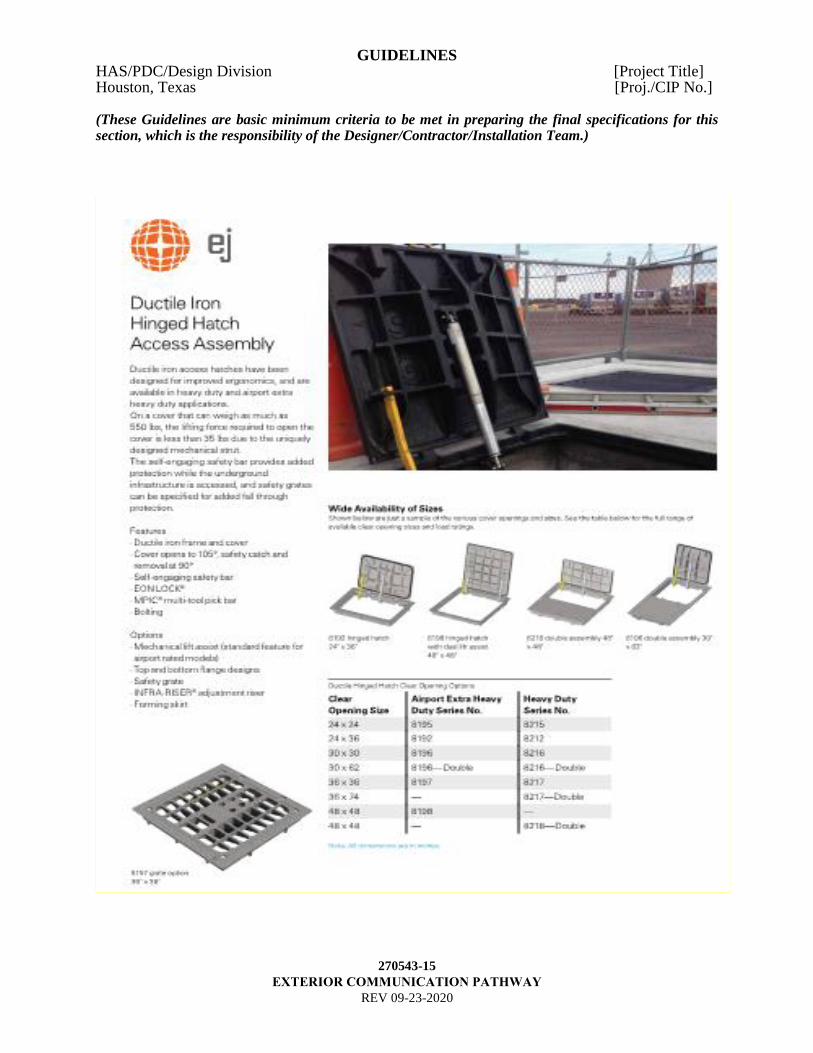
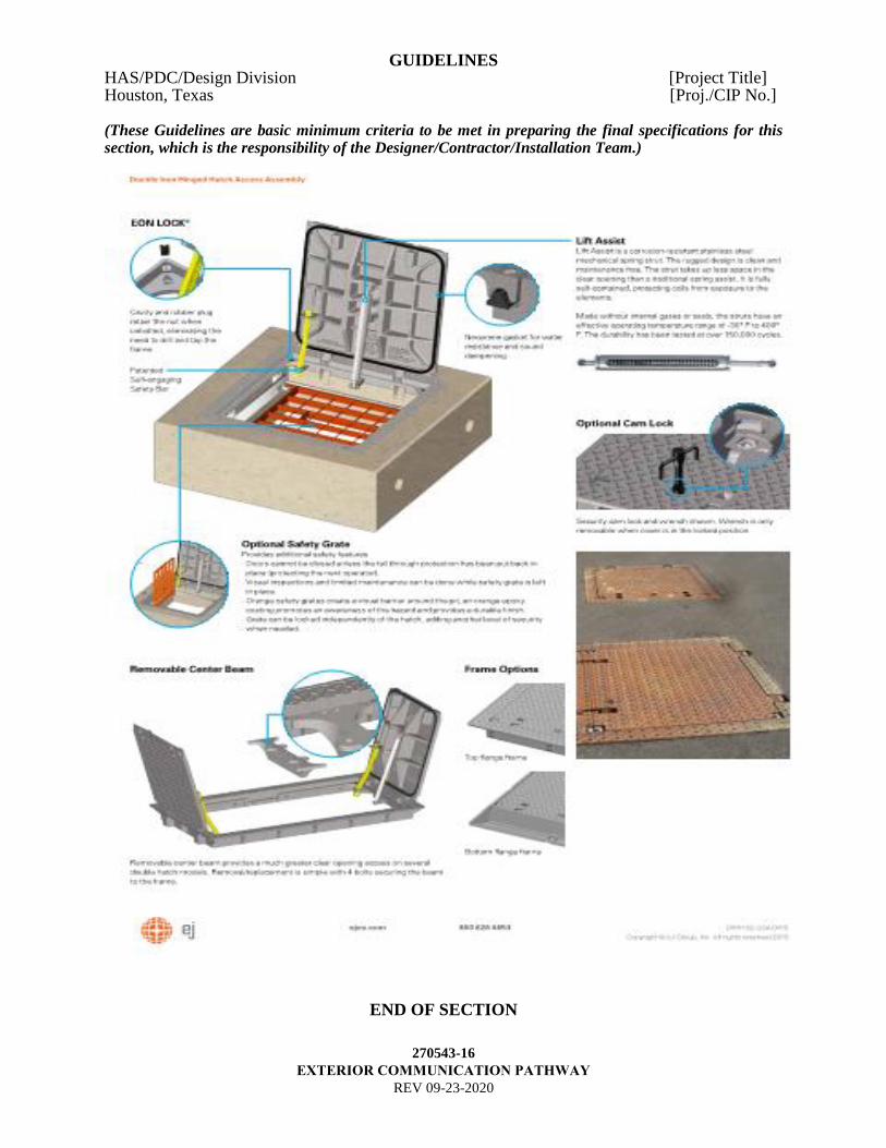
F. HH cover: Shall require a maximum 35-lb lift to open and close
1. Cover and service lettering shall be abrasion, corrosion, chemical resistant and slip
resistant surface.
2. Door shall use a non-load bearing, internally mounted hinge mechanism and shall
have a high visibility warning label affixed to the underside
3. The cover shall be removable from the cover frame assembly with a minimum
opening clearance size of 36” x 36” (See attached figure 1 part number 8197)
4. A prototype test report for each cover style to be installed shall be submitted. The
testing shall be conducted by an independent testing company and shall conform to
the following:
a. Carry a proof load of 29,250 lbs. applied at 150 psi without deformation or injury
to the cover
b. Carry a maximum HS20 service load, applied at 100 psi for a minimum of
525,000 cycles without losing its service life
c. Carry a maximum HS20 service load applied continuously at 100 psi for twelve
continuous hours without exhibiting an increase in residual deflection, as
measured at the center of the cover, of more than 0.4% (0.004)
d. Covers have a modulus of elasticity of, at least, 3,500,000 psi, a flexural strength
of 53,000 psi, and a compressive strength of 62,000 psi.
5. AOA covers to meet or exceed FAA loading standards.
6. All HH covers shall include the following (see attached figure 1):
a. Slip Resistant surface
b. Four (4) ½-13 x 2 ¼” Hex bolts with Stainless Steel washers
c. “HOUSTON AIRPORT SYSTEM” shall be cased on the lid ½” FLAT FACE
GOTHIC. (See attached figure 1).
d. “HAS COMMUNICATIONS” shall be casted on lid ¼” FLAT FACE GOTHIC.
(See attached figure 1).
e. “TELECOM” shall be cast on lid 2” FLAT FACE GOTHIC. (See attached figure
1).
f. Submit proof for approval prior to customizing covers.
g. Obtain permanent HH number from HAS IT. Field punch or weld MH number at
time of installation.
GUIDELINES HAS/PDC/Design Division [Project Title] Houston, Texas [Proj./CIP No.] (These Guidelines are basic minimum criteria to be met in preparing the final specifications for this section, which is the responsibility of the Designer/Contractor/Installation Team.)
270543-6
EXTERIOR COMMUNICATION PATHWAY
REV 09-23-2020
h. Submit cross reference table with construction MH number and permanent MH
number.
i. All cover and hinge hardware shall be stainless steel.
j. All covers shall have a Security camlock and MPIC multi-tool pick bar.
k. Ram-Nek shall be installed in between the handhole, frame and cover.
l. All covers shall a self-engaging safety bar and a stainless-steel mechanical spring
strut for lift assist. Cover shall open to 105 degrees, safety catch and removal at
90 degrees.
G. AOA HH will be 48” x 48” x 48” and constructed of 8-inch-thick concrete covered
with 250 psi, aircraft rated cover plates containing an approved locking device with a
35-pound lift to open and close.
1. All HH covers shall include the follows:
a. Slip Resistant surface
b. Four (4) ½-13 x 2 ¼” Hex bolts with SS washers
c. “HOUSTON AIRPORT SYSTEM” shall be cased on the lid ½” FLAT FACE
GOTHIC. (See attached figure 1).
d. “HAS COMMUNICATIONS” shall be casted on lid ¼” FLAT FACE GOTHIC.
(See attached figure 1).
e. “TELECOM” shall be cast on lid 2” FLAT FACE GOTHIC. (See attached figure
1).
f. Submit proof for approval prior to customizing covers.
g. Obtain permanent HH number from HAS IT. Field punch or weld MH number at
time of installation.
h. Submit cross reference table with construction MH number and permanent MH
number.
i. All cover and hinge hardware shall be stainless steel.
j. All covers shall have a Security camlock and MPIC multi-tool pick bar.
k. Ram-Nek shall be installed in between the manhole, frame, and cover.
l. All covers shall a self-engaging safety bar and a stainless-steel mechanical spring
strut for lift assist. Cover shall open to 105 degrees, safety catch and removal at
90 degrees
H. Concrete and Reinforcing Steel for Encasement: Furnish products following Section
01610 and Division 3 except strengths as follows:
1. Compressive Strength: 2500 psi at 28 days, class A.
2. Flexural Strength: 500 psi at 28 days.
3. Dye concrete encasement “ORANGE” to identify Communication Duct banks.
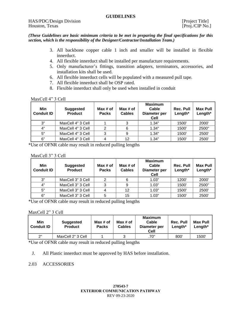
I. Flexible Innerduct: (Designer to ensure cell size matches cable requirements)
1. Flexible innerduct is the HAS standard for multi-path applications within conduit.
2. All backbone fiber shall be installed in flexible innerduct.
GUIDELINES HAS/PDC/Design Division [Project Title] Houston, Texas [Proj./CIP No.] (These Guidelines are basic minimum criteria to be met in preparing the final specifications for this section, which is the responsibility of the Designer/Contractor/Installation Team.)
270543-7
EXTERIOR COMMUNICATION PATHWAY
REV 09-23-2020
3. All backbone copper cable 1 inch and smaller will be installed in flexible
innerduct.
4. All flexible innerduct shall be installed per manufacture requirements.
5. Only manufacturer’s fittings, transition adapters, terminators, accessories, and
installation kits shall be used.
6. All flexible innerduct cells will be populated with a measured pull tape.
7. All flexible innerduct shall be OSP rated.
8. Flexible innerduct shall only be used when installed in conduit
MaxCell 4” 3 Cell
Min Conduit ID
Suggested Product
Max # of Packs
Max # of Cables
Maximum Cable
Diameter per Cell
Rec. Pull Length*
Max Pull Length*
3" MaxCell 4" 3 Cell 1 3 1.34" 1500' 2000'
4" MaxCell 4" 3 Cell 2 6 1.34" 1500' 2500"
5" MaxCell 4" 3 Cell 3 9 1.34" 1500' 2500'
6" MaxCell 4" 3 Cell 4 12 1.34" 1500' 2500'
*Use of OFNR cable may result in reduced pulling lengths
MaxCell 3” 3 Cell
Min Conduit ID
Suggested Product
Max # of Packs
Max # of Cables
Maximum Cable
Diameter per Cell
Rec. Pull Length*
Max Pull Length*
3" MaxCell 3" 3 Cell 2 6 1.03" 1200' 2000'
4" MaxCell 3" 3 Cell 3 9 1.03" 1500' 2500"
5" MaxCell 3" 3 Cell 4 12 1.03" 1500' 2500'
6" MaxCell 3" 3 Cell 5 15 1.03" 1500' 2500'
*Use of OFNR cable may result in reduced pulling lengths
MaxCell 2” 3 Cell
Min Conduit ID
Suggested Product
Max # of Packs
Max # of Cables
Maximum Cable
Diameter per Cell
Rec. Pull Length*
Max Pull Length*
2" MaxCell 2" 3 Cell 1 3 .70" 800' 1500'
*Use of OFNR cable may result in reduced pulling lengths
J. All Plastic innerduct must be approved by HAS before installation.
2.03 ACCESSORIES
GUIDELINES HAS/PDC/Design Division [Project Title] Houston, Texas [Proj./CIP No.] (These Guidelines are basic minimum criteria to be met in preparing the final specifications for this section, which is the responsibility of the Designer/Contractor/Installation Team.)
270543-8
EXTERIOR COMMUNICATION PATHWAY
REV 09-23-2020
A. Continuous Tape for Underground Conduit: orange warning ribbon, PVC tape
(detectable, i.e., containing metallic tracings), minimum 5 mils thick and 3 inches wide,
permanently imprinted with "CAUTION--BURIED COMMUNICATIONS LINE
BELOW" in black letters, minimum 1-inch high.
PART 3 EXECUTION
3.01 PREPARATION
A. Verify materials are on site in proper condition and of sufficient quantity.
B. Verify proper excavation depth; verify width route and support of work. (Division 2).
Ducts shall be installed so that the tops of all ducts are at least 36 inches below the
finished grade. Verify proper location of hand holes and MH (maximum every 600 feet).
Communications facilities must be placed in separate MH/HH from electrical facilities.
C. Trenches greater than or equal to 5 feet deep:
1. Shall be shored to prevent cave-in.
2. Shall have 2 feet clearance from the dirt pile.
D. Directional boring (HAS IT prior approval required) is a suitable substitute when
trenching is impractical or impossible. Bore logs shall be submitted as deliverables along
with the GPS/GIS data information to include but not limited to, depth every 10-12 feet,
x and y coordinates. Refer spec section 270553 for the GIS data collocation deliverable.
A 6-gauge trace wire shall be installed with the conduit. Locating existing underground
utilities is crucial when directional boring is planned because of the potential for the
drilling unit to encounter high voltages. Although directional boring machines are
manufactured with electrical strike sensing capabilities, which can warn the operator of
any contact with a high voltage source, accidents may still occur.
1. Operators of directional boring machines require special protection due to the
potential for exposure to high voltage. Therefore, operators shall always have a
ground mat grid underfoot as insulation protection. In addition, operators shall wear
insulating boots and gloves, along with hard hats and safety glasses.
2. Casings shall be installed when boring conduits under streets, roadways, runways and
or taxiways.
E. Minimum electrical/communications underground cable separation:
1. Concrete: 3 inches
2. Masonry: 4 inches
3. Well-tamped earth: 12 inches
4. Electrical: 12 inches

GUIDELINES HAS/PDC/Design Division [Project Title] Houston, Texas [Proj./CIP No.] (These Guidelines are basic minimum criteria to be met in preparing the final specifications for this section, which is the responsibility of the Designer/Contractor/Installation Team.)
270543-9
EXTERIOR COMMUNICATION PATHWAY
REV 09-23-2020
F. Before encasement, verify ducts are free of debris and properly installed in support and
spacer system, are properly fitted together and hold-down hardware is properly installed.
3.02 INSTALLATION
A. Prior to installation, the contractor shall comply with Specification 270553 referencing
GIS GPS requirements during the installation of all manholes / handholes and duct banks.
B. Install all work following drawings, manufacturer’s instructions and approved submittal
data.
C. Install conduit in excavations following Drawings. If directional boring is utilized, cable
or flexible conduits can be attached to the unit and pulled back to the origination point
(after the drilling unit reaches its destination).
D. HH shall be 48” x 48” x 48” and shall be constructed of two-inch thick concrete covered
with 3/8-inch steel plate. The hand hole or MH shall rest on a 4-inch blanket of 2 sack
stabilized sand, and 4 inches around the side walls shall be filled with 2 sack stabilized
sand. Refer to Division 02321.
E. Each MH/HH that contains a pedestal will have four bollards installed 18 inches
diagonally from each corner, with a cross member welded at 30 inches connecting the
Four Corners. These barriers will be constructed of 4-inch ridged conduit filled with
concrete, driven four feet in the ground and extending 36 inches above the protective
cover.
F. Install watertight penetrations through foundation, HH, and MH walls. Wherever a hand
hole is used to simply pass through, the conduit entrances and exits shall be situated at
opposite ends of the hand hole instead of 90-degree angles.
G. Assemble duct banks with non-magnetic saddles, spacers and separators. Position
separators for 2-inch minimum concrete separation between outer surfaces of adjacent
ducts.
1. Make uniform required bends with a minimum of a 24-inch radius for conduits less
than 3-inch diameter, and a 48-inch radius for conduits 3 inches and larger.
2. Maintain vertical or horizontal separations of 12 inches of well-packed topsoil from
any electrical service conduit run parallel to Communications conduits.
H. Install reinforcing. Install concrete encasement surrounding reinforcing steel and ducts.
Follow Section 03315 using one-inch maximum size course aggregate concrete.
GUIDELINES HAS/PDC/Design Division [Project Title] Houston, Texas [Proj./CIP No.] (These Guidelines are basic minimum criteria to be met in preparing the final specifications for this section, which is the responsibility of the Designer/Contractor/Installation Team.)
270543-10
EXTERIOR COMMUNICATION PATHWAY
REV 09-23-2020
1. Unless otherwise noted on the drawings, reinforce with No. 4 longitudinal steel bars
placed at each corner and along each face at maximum parallel spacing of 12 inches
o.c., and No. 3 tie-bars transversely placed at 12 inches o.c. maximum longitudinal.
Maintain maximum clearance of 2 inches from bars to edge of forms and ducts.
2. Sprinkle ORANGE colorants on top of concrete.
a. ORANGE: For Telecommunications.
3. Place concrete with minimum 3-inch cover surrounding ducts and reinforcement.
4. Maintain ducts in proper place during concrete placement.
I. Transition from non-metallic to PVC coated metallic conduit where duct banks enter
structures or turn upward for continuation above grade.
1. With prior HAS/IT APPROVAL. For conduit runs (1” to 4”) a special LBD condulet
(Crouse-Hinds or approved equal) may be used for exterior wall penetration where a
swept 90 will not work. LBD condulets are designed for communications cable
installation to maintain bend radius requirements.
J. Where ducts enter structures such as HH, MH, pull boxes, or buildings, terminate ducts in
proper end bells, provide insulated L-bushings and grout walls at the conduit entrance
points. Terminators or bells shall be installed at the wall for a flush installation. All ducts
shall be sealed with Meyers hubs or couplings on steel conduits ducts and/or sealed with
watertight mechanical plugs with a max back Air Pressure 17 PSI, Max Back Pressure 40
ft of Head.
K. Extend below grade conduits to 4 inches above the finished floor inside a building.
L. Tag conduits entering pull boxes with stamped stainless-steel tags following cable and
conduit schedule.
M. Install continuous, orange warning ribbon, PVC tape (detectable, i.e., containing metallic
tracings), 3 inches wide, permanently imprinted with "CAUTION - BURIED
COMMUNICATIONS LINE BELOW" in black letters, approximately 12 inches below
finished grade following line of duct banks.
N. Expansion Fittings:
1. Raceways shall be provided with expansion fitting where necessary to compensate for
thermal expansion and contraction.
2. Use expansion-deflection fittings on conduit crossing structural expansion joints and
on exposed conduit funs where necessary. Provide bonding jumpers across fittings in
metal raceways systems
3.03 BACKFILLING

GUIDELINES HAS/PDC/Design Division [Project Title] Houston, Texas [Proj./CIP No.] (These Guidelines are basic minimum criteria to be met in preparing the final specifications for this section, which is the responsibility of the Designer/Contractor/Installation Team.)
270543-11
EXTERIOR COMMUNICATION PATHWAY
REV 09-23-2020
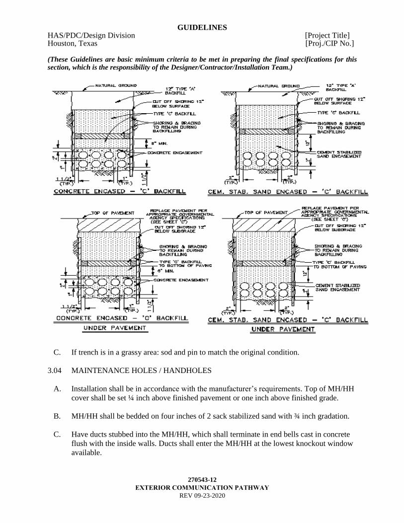
A. Backfill following Division 02320 after concrete cures 24 hours. After concrete encased
ducts have been properly installed, and the concrete has had time to set, the trench shall
be backfilled in at least two layers with excavated material, not larger than four inches in
diameter, thoroughly tamped, and compacted to at least the density of the surrounding
undisturbed soil. If necessary to obtain the desired compaction, the backfill material shall
be moistened or aerated as required. Trenches shall not be excessively wet and shall not
contain pools of water during backfill operations. The trench shall be completely
backfilled and compacted level with the adjacent surface. Any excess excavated material
shall be removed and disposed of offsite at the contractor’s expense.
B. Type ‘C’ Backfill Cement Stabilized Sand
Two (2) sack stabilized sand is authorized only with HAS IT Infrastructures prior
approval. Compact 2 sack stabilized sand in 6” to 8” lifts to a 95% of maximum density
as determined in accordance with ASTM D558, ASTM D698 and ASTM D1633, unless
otherwise specified in spec section 02321. Perform and complete compaction of 2 sack
stabilize cement mixture within 4 hours from the load delivery receipt.
GUIDELINES HAS/PDC/Design Division [Project Title] Houston, Texas [Proj./CIP No.] (These Guidelines are basic minimum criteria to be met in preparing the final specifications for this section, which is the responsibility of the Designer/Contractor/Installation Team.)
270543-12
EXTERIOR COMMUNICATION PATHWAY
REV 09-23-2020
C. If trench is in a grassy area: sod and pin to match the original condition.
3.04 MAINTENANCE HOLES / HANDHOLES
A. Installation shall be in accordance with the manufacturer’s requirements. Top of MH/HH
cover shall be set ¼ inch above finished pavement or one inch above finished grade.
B. MH/HH shall be bedded on four inches of 2 sack stabilized sand with ¾ inch gradation.
C. Have ducts stubbed into the MH/HH, which shall terminate in end bells cast in concrete
flush with the inside walls. Ducts shall enter the MH/HH at the lowest knockout window
available.
GUIDELINES HAS/PDC/Design Division [Project Title] Houston, Texas [Proj./CIP No.] (These Guidelines are basic minimum criteria to be met in preparing the final specifications for this section, which is the responsibility of the Designer/Contractor/Installation Team.)
270543-13
EXTERIOR COMMUNICATION PATHWAY
REV 09-23-2020
D. MH/HH shall be fitted on each wall with cable racks and struts. Each rack shall be
provided with a minimum of four rack type arms. Rack arms shall be made of non-
flammable polymer.
E. MH shall be provided with a pulling eye on each end and a drainage sump in the bottom.
F. HH shall be provided with a pulling eye on each end and a drainage sump in the bottom.
G. MH/HH shall be provided with a ¾ inch by 10-foot stainless steel ground rod in each
MH. See Section 270526 for ground rod specification. Do not install the ground rod
through the drain sump. Install through a prepared opening and grout fill after
installation.
H. All vacant ducts shall be sealed with an HAS and Industry approved water-tight and gas-
tight mechanical plugs with max back Air Pressure 17 PSI, Max Back Pressure 40 ft of
Head.
I. All flexible innerducts and plastic innerducts shall be sealed with an HAS and Industry
approved watertight and gas-tight plugs.
J. All occupied ducts shall be sealed with Triplex duct plugs, Quadplex duct plugs or HAS
and Industry approved water-tight and gas-tight plugs.
K. Where more than one innerduct is routed in a conduit, each innerduct shall consist of a
different color (ex. Orange, Blue, Black and White). HAS-IT approval required before
installation.
L. When populating duct bank with plastic innerduct the following apply: HAS-IT approval
required before installation.
1. Innerduct to be OSP rated
2. 4” duct to be populated with no less than 3-1.25 inch innerducts
3. 4” duct to be populated with no less than 4-1 inch innerducts
M. All fiber cables shall be placed in flexible innerduct and comply with 271300 guidelines.
N. All copper cables 100 pairs or less shall be placed in flexible innerduct.
O. A 12-inch-long mandrel shall be swabbed through all ducts to remove debris until shown
clean (1/4 inch smaller than duct diameter).
P. A conduit measuring tape, with a minimum test rating of 1250 pounds of pulling tension
shall be installed in all underground conduits, flexible innerducts and plastic innerduct

GUIDELINES HAS/PDC/Design Division [Project Title] Houston, Texas [Proj./CIP No.] (These Guidelines are basic minimum criteria to be met in preparing the final specifications for this section, which is the responsibility of the Designer/Contractor/Installation Team.)
270543-14
EXTERIOR COMMUNICATION PATHWAY
REV 09-23-2020
when applicable. Label each end of the duct bank in every MH to ensure continuity per
specification 270553.
3.05 IDENTIFIERS, LABELS AND LABELING SYSTEM
A. All Identification and Labeling shall follow Specification: 270553–Identification and
Labeling of Communication Infrastructure. Any deviation from the specification must
be approved by HAS IT prior to installation.
Figure 1
GUIDELINES HAS/PDC/Design Division [Project Title] Houston, Texas [Proj./CIP No.] (These Guidelines are basic minimum criteria to be met in preparing the final specifications for this section, which is the responsibility of the Designer/Contractor/Installation Team.)
270543-15
EXTERIOR COMMUNICATION PATHWAY
REV 09-23-2020
GUIDELINES HAS/PDC/Design Division [Project Title] Houston, Texas [Proj./CIP No.] (These Guidelines are basic minimum criteria to be met in preparing the final specifications for this section, which is the responsibility of the Designer/Contractor/Installation Team.)
270543-16
EXTERIOR COMMUNICATION PATHWAY
REV 09-23-2020
END OF SECTION