SPECIFIC PLAN - City of Moreno Valley, California · SPECIFIC PLAN September 2014 City of Moreno...
219
TM R THE WORLD LOGISTICS CENTER Adopted: Date: Ordinance # SPECIFIC PLAN September 2014 City of Moreno Valley Riverside County, California August 25, 2015 900
Transcript of SPECIFIC PLAN - City of Moreno Valley, California · SPECIFIC PLAN September 2014 City of Moreno...
TM
R
THE WORLDLOGISTICS CENTER
Adopted:
Date: Ordinance #
SPECIFIC PLANSeptember 2014
City of Moreno ValleyRiverside County, California
August 25, 2015
900
DISCLAIMER
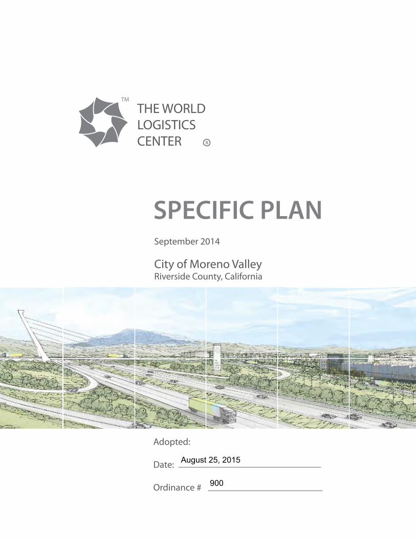
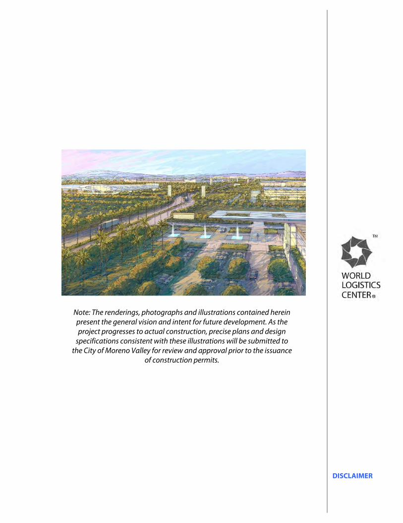
Note: The renderings, photographs and illustrations contained herein present the general vision and intent for future development. As the project progresses to actual construction, precise plans and design
specifications consistent with these illustrations will be submitted to the City of Moreno Valley for review and approval prior to the issuance
of construction permits.
TABLE OF CONTENTS i
TABLE OF CONTENTS 1.0 INTRODUCTION 1-1
1.1 The World Logistics Center 1-1 1.2 Specific Plan Overview 1-1 1.3 Specific Plan Vision and Objectives 1-2
1.3.1 Development Goals 1-3 1.3.2 Green Building-Sustainable Development 1-4 1.3.3 Sense of Place 1-5 1.3.4 Project Infrastructure 1-5
1.4 Existing Setting 1-6 1.4.1 Existing Land Use 1-6 1.4.2 Existing Fault Zones 1-7
2.0 LAND USE PLAN 2-1
2.1 World Logistics Center Land Use Designations 2-1 2.2 Logistics Development (LD) Category 2-4
2.2.1 Purpose and Intent 2-4 2.2.2 Permitted Uses 2-4 2.2.3 Development Standards 2-4 2.2.4 Fire Station Site 2-6 2.2.5 Logistics Support 2-7
2.3 Light Logistics (LL) Category 2-9 2.3.1 Purpose and Intent 2-9 2.3.2 Permitted Uses 2-9 2.3.3 Development Standards 2-9
2.4 Standards and Guidelines For Open Space 2-11 2.5 Special Edge Treatment Areas 2-12
2.5.1 Western Edge 2-12 2.5.2 SR-60 Edge 2-12 2.5.3 SJWA Edge 2-12 2.5.4 Gilman Springs Road Edge 2-12 2.5.5 Concept Plans 2-13
3.0 INFRASTRUCTURE PLAN 3-1
3.1 Circulation 3-1 3.2 Freeway 3-2 3.3 Vehicular Circulation 3-2
3.3.1 Passenger Car and Truck Circulation 3-2 3.3.2 Street Designations 3-3 3.3.3 Truck Circulation 3-8
3.3.4 Mass Transit Circulation 3-11 3.3.5 Emergency Access 3-12
3.4 Non Vehicular Circulation 3-12 3.4.1 Pedestrian Circulation 3-12
TABLE OF CONTENTS ii
3.4.2 Multi-Use Trails 3-13 3.4.3 Bicycle Circulation 3-14
3.5 Utilities 3-14 3.5.1 Water 3-14 3.5.2 Sewer 3-16 3.5.3 Recycled Water 3-17 3.5.4 Storm Drain 3-18 3.5.5 Utility Conditions 3-20
4.0 OFF-SITE DESIGN STANDARDS 4-1
4.1 Off-site Architecture 4-1 4.1.1 Objectives 4-1 4.1.2 Ground-mounted Equipment 4-1 4.1.3 Roof-mounted Equipment 4-1
4.2 Off-site Landscaping 4-2 4.2.1 Objectives 4-2 4.2.2 Water Conservation Measures 4-2 4.2.3 Streetscapes 4-5
4.2.3.1 General Design Criteria 4-5 4.2.4 Special Edge Treatment Areas 4-6
4.2.4.1 Western Edge 4-7 4.2.4.2 SR-60 Edge 4-9 4.2.4.3 SJWA Edge 4-10 4.2.4.4 Gilman Springs Road Edge 4-12
4.2.5 Screening Criteria for Interior Roadways 4-13 4.2.6 Perimeter Planting 4-14 4.2.7 Roundabout & Entry 4-30 4.2.8 Streetscape Planting 4-37 4.2.9 Off-site Plant Selection 4-43 4.2.10 Off-site Maintenance 4-45
4.3 Off-site Lighting 4-45 4.3.1 Objectives 4-45
4.4 Off-site Utilities 4-45 4.4.1 Telephone, CATV and Similar Service Wires and Cables 4-45 4.4.2 Electrical Transmission Lines 4-45
5.0 ON-SITE DESIGN STANDARDS 5-1
5.1 On-site Design Standards and Guidelines 5-1 5.1.1 General Purpose 5-1 5.1.2 Uses Shall be Developed in Accordance 5-1
with the Specific Plan 5.1.3 Uses Shall be Developed in Accordance 5-1
with City of Moreno Valley Municipal Codes 5.1.4 Subdivision Map Act 5-2 5.1.5 Water Quality Management Plan 5-2 5.1.6 Trash and Recyclable Materials 5-2
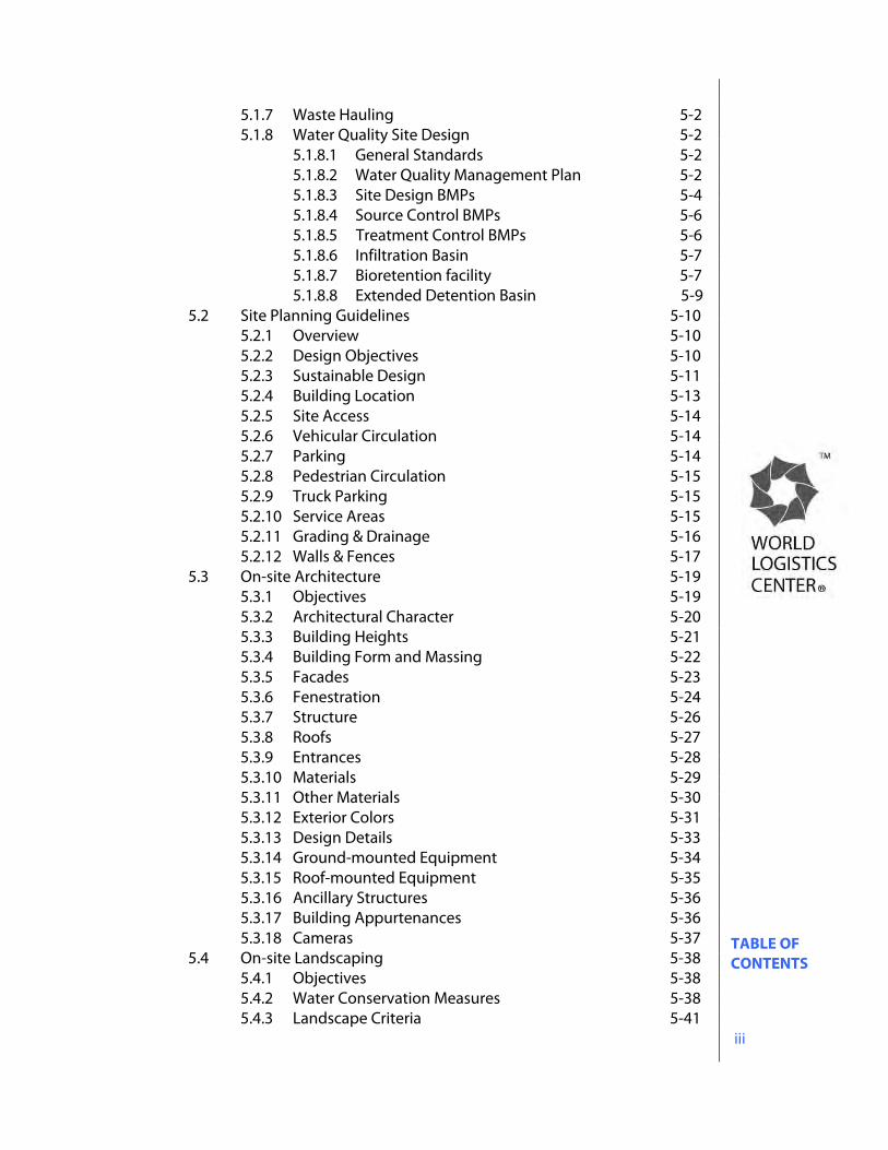
TABLE OF CONTENTS iii
5.1.7 Waste Hauling 5-2 5.1.8 Water Quality Site Design 5-2
5.1.8.1 General Standards 5-2 5.1.8.2 Water Quality Management Plan 5-2 5.1.8.3 Site Design BMPs 5-4 5.1.8.4 Source Control BMPs 5-6 5.1.8.5 Treatment Control BMPs 5-6 5.1.8.6 Infiltration Basin 5-7 5.1.8.7 Bioretention facility 5-7 5.1.8.8 Extended Detention Basin 5-9
5.2 Site Planning Guidelines 5-10 5.2.1 Overview 5-10 5.2.2 Design Objectives 5-10 5.2.3 Sustainable Design 5-11 5.2.4 Building Location 5-13 5.2.5 Site Access 5-14 5.2.6 Vehicular Circulation 5-14 5.2.7 Parking 5-14 5.2.8 Pedestrian Circulation 5-15 5.2.9 Truck Parking 5-15 5.2.10 Service Areas 5-15 5.2.11 Grading & Drainage 5-16 5.2.12 Walls & Fences 5-17
5.3 On-site Architecture 5-19 5.3.1 Objectives 5-19 5.3.2 Architectural Character 5-20 5.3.3 Building Heights 5-21 5.3.4 Building Form and Massing 5-22 5.3.5 Facades 5-23 5.3.6 Fenestration 5-24 5.3.7 Structure 5-26 5.3.8 Roofs 5-27 5.3.9 Entrances 5-28 5.3.10 Materials 5-29 5.3.11 Other Materials 5-30 5.3.12 Exterior Colors 5-31 5.3.13 Design Details 5-33 5.3.14 Ground-mounted Equipment 5-34 5.3.15 Roof-mounted Equipment 5-35 5.3.16 Ancillary Structures 5-36 5.3.17 Building Appurtenances 5-36 5.3.18 Cameras 5-37
5.4 On-site Landscaping 5-38 5.4.1 Objectives 5-38 5.4.2 Water Conservation Measures 5-38 5.4.3 Landscape Criteria 5-41
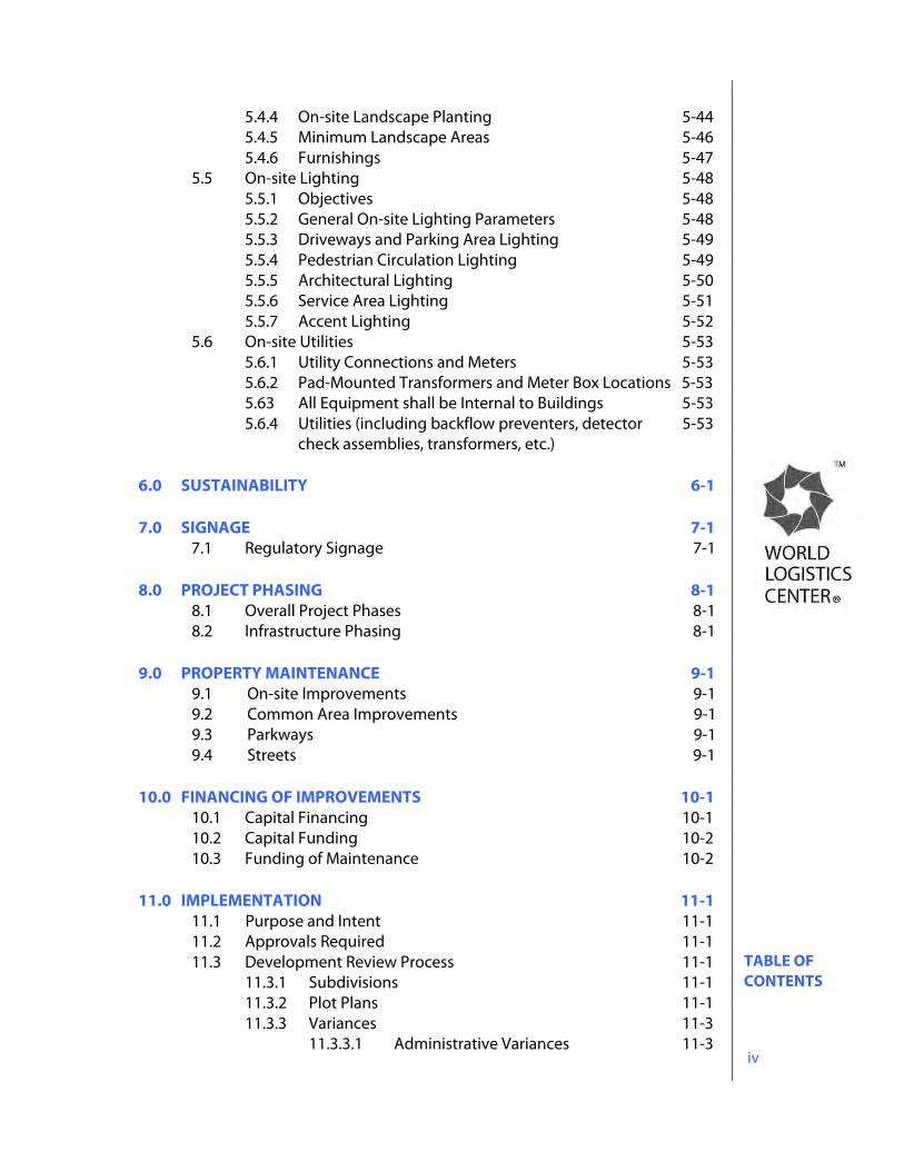
TABLE OF CONTENTS iv
5.4.4 On-site Landscape Planting 5-44 5.4.5 Minimum Landscape Areas 5-46 5.4.6 Furnishings 5-47
5.5 On-site Lighting 5-48 5.5.1 Objectives 5-48 5.5.2 General On-site Lighting Parameters 5-48 5.5.3 Driveways and Parking Area Lighting 5-49 5.5.4 Pedestrian Circulation Lighting 5-49 5.5.5 Architectural Lighting 5-50 5.5.6 Service Area Lighting 5-51 5.5.7 Accent Lighting 5-52
5.6 On-site Utilities 5-53 5.6.1 Utility Connections and Meters 5-53 5.6.2 Pad-Mounted Transformers and Meter Box Locations 5-53 5.63 All Equipment shall be Internal to Buildings 5-53 5.6.4 Utilities (including backflow preventers, detector 5-53 check assemblies, transformers, etc.)
6.0 SUSTAINABILITY 6-1 7.0 SIGNAGE 7-1 7.1 Regulatory Signage 7-1 8.0 PROJECT PHASING 8-1
8.1 Overall Project Phases 8-1 8.2 Infrastructure Phasing 8-1
9.0 PROPERTY MAINTENANCE 9-1
9.1 On-site Improvements 9-1 9.2 Common Area Improvements 9-1 9.3 Parkways 9-1 9.4 Streets 9-1
10.0 FINANCING OF IMPROVEMENTS 10-1
10.1 Capital Financing 10-1 10.2 Capital Funding 10-2 10.3 Funding of Maintenance 10-2
11.0 IMPLEMENTATION 11-1
11.1 Purpose and Intent 11-1 11.2 Approvals Required 11-1 11.3 Development Review Process 11-1
11.3.1 Subdivisions 11-1 11.3.2 Plot Plans 11-1 11.3.3 Variances 11-3 11.3.3.1 Administrative Variances 11-3
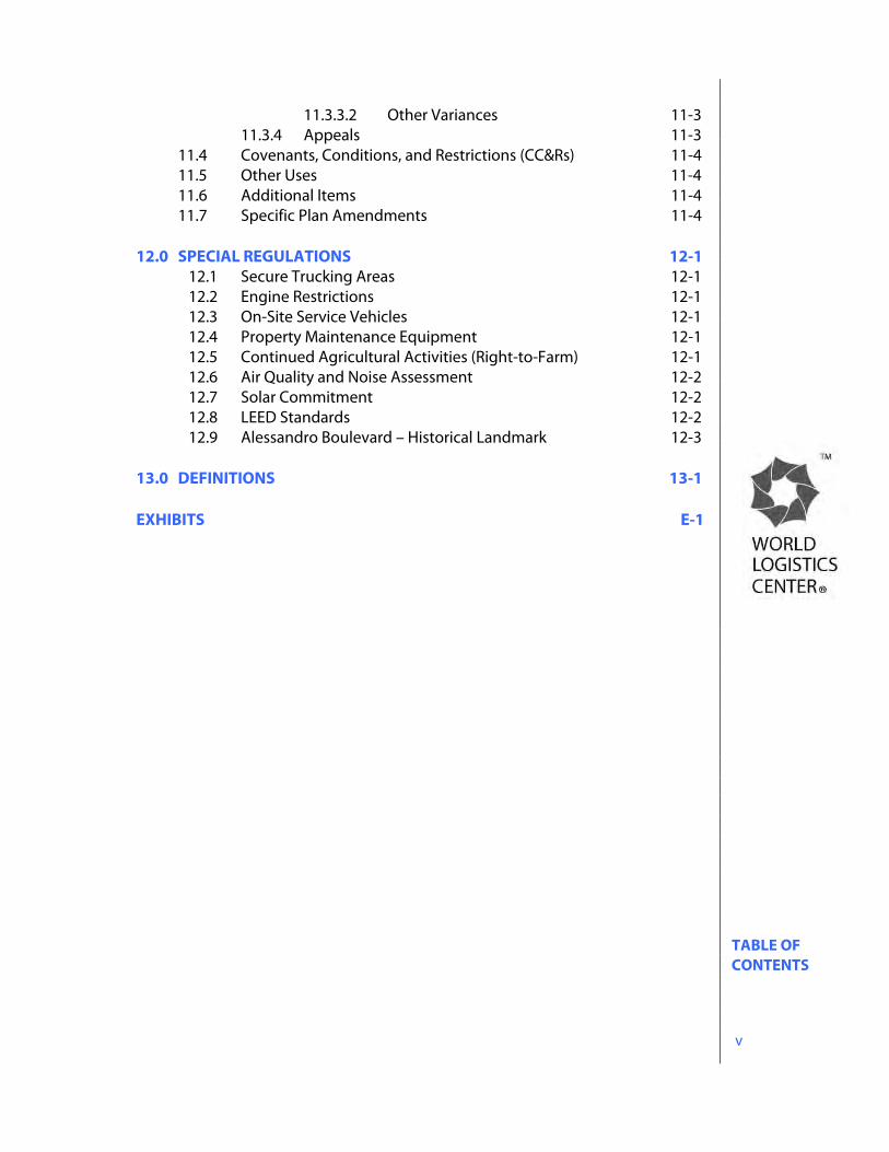
TABLE OF CONTENTS v
11.3.3.2 Other Variances 11-3 11.3.4 Appeals 11-3
11.4 Covenants, Conditions, and Restrictions (CC&Rs) 11-4 11.5 Other Uses 11-4 11.6 Additional Items 11-4 11.7 Specific Plan Amendments 11-4
12.0 SPECIAL REGULATIONS 12-1
12.1 Secure Trucking Areas 12-1 12.2 Engine Restrictions 12-1 12.3 On-Site Service Vehicles 12-1 12.4 Property Maintenance Equipment 12-1 12.5 Continued Agricultural Activities (Right-to-Farm) 12-1 12.6 Air Quality and Noise Assessment 12-2 12.7 Solar Commitment 12-2 12.8 LEED Standards 12-2 12.9 Alessandro Boulevard – Historical Landmark 12-3
13.0 DEFINITIONS 13-1 EXHIBITS E-1
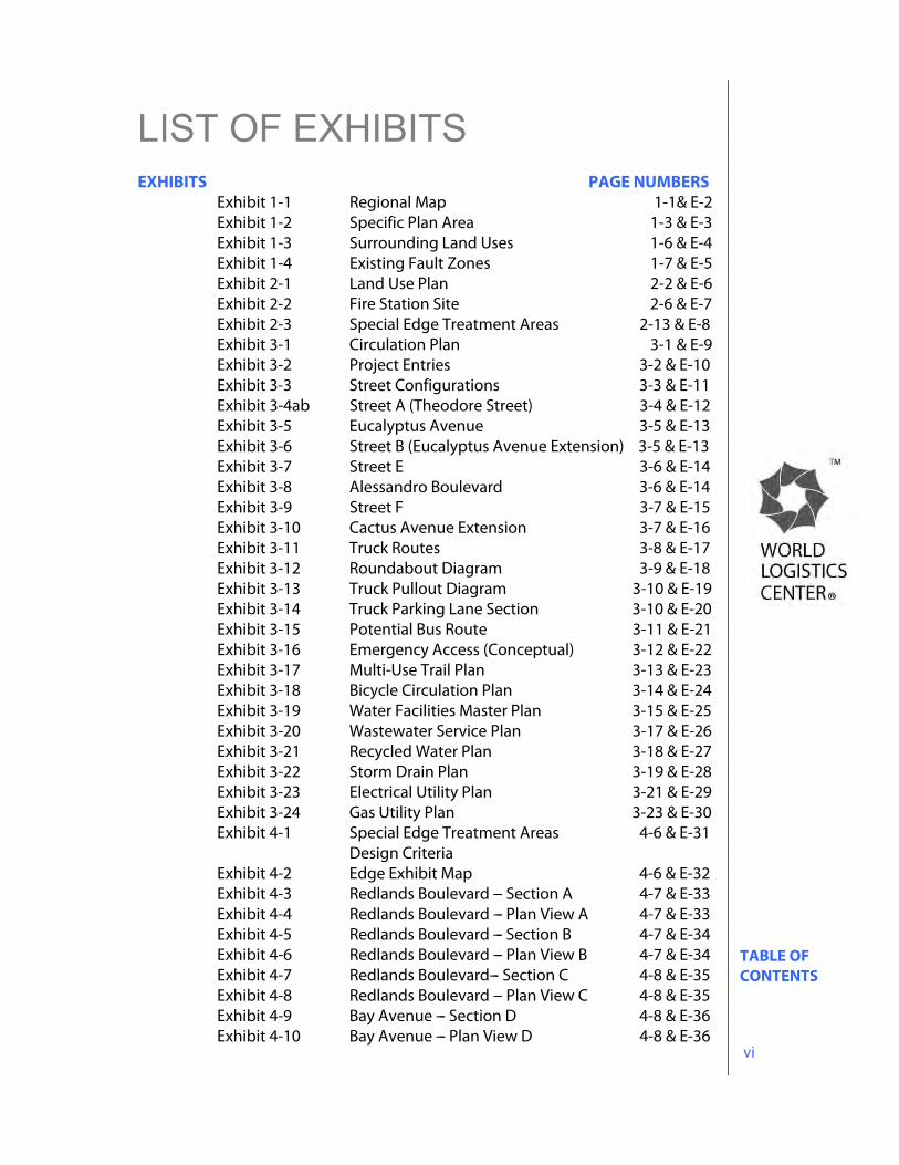
TABLE OF CONTENTS vi
LIST OF EXHIBITS EXHIBITS PAGE NUMBERS
Exhibit 1-1 Regional Map 1-1& E-2 Exhibit 1-2 Specific Plan Area 1-3 & E-3 Exhibit 1-3 Surrounding Land Uses 1-6 & E-4 Exhibit 1-4 Existing Fault Zones 1-7 & E-5 Exhibit 2-1 Land Use Plan 2-2 & E-6 Exhibit 2-2 Fire Station Site 2-6 & E-7 Exhibit 2-3 Special Edge Treatment Areas 2-13 & E-8 Exhibit 3-1 Circulation Plan 3-1 & E-9 Exhibit 3-2 Project Entries 3-2 & E-10 Exhibit 3-3 Street Configurations 3-3 & E-11 Exhibit 3-4ab Street A (Theodore Street) 3-4 & E-12 Exhibit 3-5 Eucalyptus Avenue 3-5 & E-13 Exhibit 3-6 Street B (Eucalyptus Avenue Extension) 3-5 & E-13 Exhibit 3-7 Street E 3-6 & E-14 Exhibit 3-8 Alessandro Boulevard 3-6 & E-14 Exhibit 3-9 Street F 3-7 & E-15 Exhibit 3-10 Cactus Avenue Extension 3-7 & E-16 Exhibit 3-11 Truck Routes 3-8 & E-17 Exhibit 3-12 Roundabout Diagram 3-9 & E-18 Exhibit 3-13 Truck Pullout Diagram 3-10 & E-19 Exhibit 3-14 Truck Parking Lane Section 3-10 & E-20 Exhibit 3-15 Potential Bus Route 3-11 & E-21 Exhibit 3-16 Emergency Access (Conceptual) 3-12 & E-22 Exhibit 3-17 Multi-Use Trail Plan 3-13 & E-23 Exhibit 3-18 Bicycle Circulation Plan 3-14 & E-24 Exhibit 3-19 Water Facilities Master Plan 3-15 & E-25 Exhibit 3-20 Wastewater Service Plan 3-17 & E-26 Exhibit 3-21 Recycled Water Plan 3-18 & E-27 Exhibit 3-22 Storm Drain Plan 3-19 & E-28 Exhibit 3-23 Electrical Utility Plan 3-21 & E-29 Exhibit 3-24 Gas Utility Plan 3-23 & E-30 Exhibit 4-1 Special Edge Treatment Areas 4-6 & E-31 Design Criteria Exhibit 4-2 Edge Exhibit Map 4-6 & E-32 Exhibit 4-3 Redlands Boulevard --- Section A 4-7 & E-33 Exhibit 4-4 Redlands Boulevard --- Plan View A 4-7 & E-33 Exhibit 4-5 Redlands Boulevard --- Section B 4-7 & E-34 Exhibit 4-6 Redlands Boulevard --- Plan View B 4-7 & E-34 Exhibit 4-7 Redlands Boulevard--- Section C 4-8 & E-35 Exhibit 4-8 Redlands Boulevard --- Plan View C 4-8 & E-35 Exhibit 4-9 Bay Avenue --- Section D 4-8 & E-36 Exhibit 4-10 Bay Avenue --- Plan View D 4-8 & E-36

TABLE OF CONTENTS vii
Exhibit 4-11 Merwin Street --- Section E 4-9 & E-37 Exhibit 4-12 Merwin Street --- Plan View E 4-9 & E-37 Exhibit 4-13 SR-60 between Theodore and 4-9 & E-38 Gilman Springs Road --- Section F Exhibit 4-14 SJWA --- Section G 4-10 & E-39 Exhibit 4-15 SJWA --- Plan View G 4-10 & E-39 Exhibit 4-16 SJWA Edge 4-11 & E-40 Exhibit 4-17 Gilman Springs Rd --- Section Downhill 4-12 & E-41 Exhibit 4-18 Gilman Springs Rd --- Section Uphill 4-12 & E-41 Exhibit 4-19 Gilman Springs Rd --- Section Flat 4-12 & E-41 Exhibit 4-20 Interior Roadways --- Section Downhill 4-13 & E-42 Exhibit 4-21 Interior Roadways --- Section Uphill 4-13 & E-42 Exhibit 4-22 Interior Roadways --- Section Flat 4-13 & E-42 Exhibit 4-23 Perimeter Planting Map 4-14 & E-43 Exhibit 4-24 Roundabout & Entry Map 4-30 & E-44 Exhibit 4-25 Streetscape Planting Map 4-37 & E-45 Exhibit 4-26 Slope Planting Guideline 4-43 & E-46 Exhibit 5-1 Water Quality Management Diagram 5-4 & E-47 Exhibit 5-2 Visitor Parking Plan 5-14 & E-48 Exhibit 5-3 Building Height Plan 5-21 & E-49 Exhibit 6-1 Off-site Water Management Plan 6-1 & E-50 Exhibit 8-1 Phasing Plan 8-1 & E-51
INTRODUCTION 1-1
1.0 INTRODUCTION
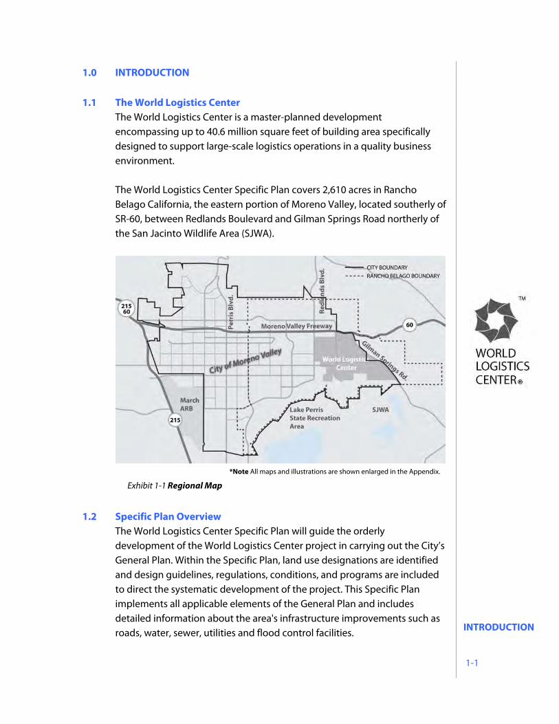
1.1 The World Logistics Center The World Logistics Center is a master-planned development encompassing up to 40.6 million square feet of building area specifically designed to support large-scale logistics operations in a quality business environment. The World Logistics Center Specific Plan covers 2,610 acres in Rancho Belago California, the eastern portion of Moreno Valley, located southerly of SR-60, between Redlands Boulevard and Gilman Springs Road northerly of the San Jacinto Wildlife Area (SJWA).
1.2 Specific Plan Overview
The World Logistics Center Specific Plan will guide the orderly development of the World Logistics Center project in carrying out the City’s General Plan. Within the Specific Plan, land use designations are identified and design guidelines, regulations, conditions, and programs are included to direct the systematic development of the project. This Specific Plan implements all applicable elements of the General Plan and includes detailed information about the area's infrastructure improvements such as roads, water, sewer, utilities and flood control facilities.
Exhibit 1-1 Regional Map
*Note All maps and illustrations are shown enlarged in the Appendix.
INTRODUCTION 1-2
The World Logistics Center Specific Plan has been adopted pursuant to Government Code Section 65450 which grants authority to cities to adopt specific plans for purposes of implementing the goals and policies of their General Plans. The Government Code sets forth the minimum requirements and review procedures for specific plans including the provision of a land use plan, infrastructure and public services plan, criteria and standards for development, and implementation measures.
The Specific Plan complies with the City of Moreno Valley’s Municipal Code (Chapter 9.13) governing the content of specific plans and procedures for their adoption and enforcement.
1.3 Specific Plan Vision and Objectives
The vision for the World Logistics Center is to establish a world class corporate park environment specifically designed to support the unique logistics and operational needs of international companies and corporate users. The World Logistics Center features a clean and contemporary design aesthetic and an efficient, convenient circulation system to provide a highly functional logistics campus. The objective of the Specific Plan is to establish the zoning criteria that will guide the orderly development of the World Logistics Center project and carry out the goals of the City’s General Plan. Included are development standards for integrated site planning, architecture, and landscaping. These standards establish a consistent design concept that produces a clear image and a sense of prestige, efficiency and integrity for the World Logistics Center and each project within.
INTRODUCTION 1-3
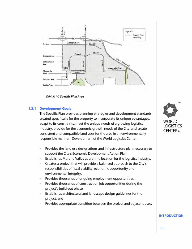
1.3.1 Development Goals
The Specific Plan provides planning strategies and development standards created specifically for the property to incorporate its unique advantages, adapt to its constraints, meet the unique needs of a growing logistics industry, provide for the economic growth needs of the City, and create consistent and compatible land uses for the area in an environmentally responsible manner. Development of the World Logistics Center: Provides the land use designations and infrastructure plan necessary to
support the City’s Economic Development Action Plan, Establishes Moreno Valley as a prime location for the logistics industry, Creates a project that will provide a balanced approach to the City’s
responsibilities of fiscal viability, economic opportunity and environmental integrity,
Provides thousands of ongoing employment opportunities, Provides thousands of construction job opportunities during the
project’s build-out phase, Establishes architectural and landscape design guidelines for the
project, and Provides appropriate transition between the project and adjacent uses.
Exhibit 1-2 Specific Plan Area
INTRODUCTION 1-4
1.3.2 Green Building – Sustainable Development Construction of the World Logistics Center will be in conformance with California’s “Cal-Green” building regulations, the most stringent, environmentally-friendly building code in the United States. Cal-Green is a comprehensive, far-reaching set of regulations which mandate environmentally-advanced building practices and regulations designed to conserve natural resources and reduce greenhouse gas emissions, energy consumption and water use. In addition, all buildings in the World Logistics Center, of at least 500,000 square feet, shall be designed to meet or exceed the LEED Certified Building Standards as described in Section 12.8. To augment its environmentally responsible building design, the project will incorporate sustainable design features to further reduce its environmental footprint, including but not limited to:
Reduced water use for landscape irrigation, Street designs that harvest and channel runoff into landscape areas
instead of storm drains, Accommodate the use of alternative means of transportation, Use recycled building materials to the extent feasible, Use local sources of building materials to the extent feasible, Minimize the use of impervious paved surfaces throughout the
project, Incorporate on-site storm water capture and infiltration within
landscape areas, Support alternative fuel use through the provision of an on-site
alternative fueling site, and Provide for the use of roof-mounted solar systems or other
alternative power systems.
INTRODUCTION 1-5
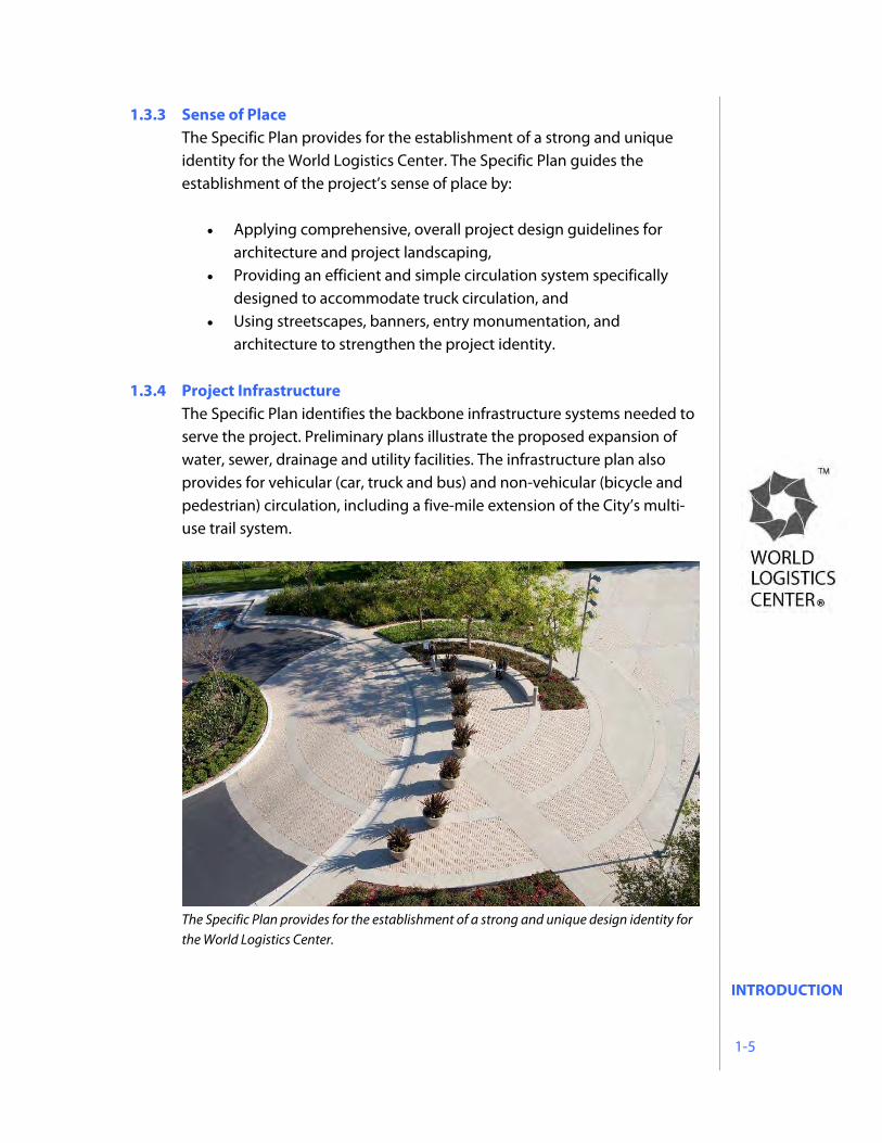
1.3.3 Sense of Place The Specific Plan provides for the establishment of a strong and unique identity for the World Logistics Center. The Specific Plan guides the establishment of the project’s sense of place by:
Applying comprehensive, overall project design guidelines for architecture and project landscaping,
Providing an efficient and simple circulation system specifically designed to accommodate truck circulation, and
Using streetscapes, banners, entry monumentation, and architecture to strengthen the project identity.
1.3.4 Project Infrastructure
The Specific Plan identifies the backbone infrastructure systems needed to serve the project. Preliminary plans illustrate the proposed expansion of water, sewer, drainage and utility facilities. The infrastructure plan also provides for vehicular (car, truck and bus) and non-vehicular (bicycle and pedestrian) circulation, including a five-mile extension of the City’s multi-use trail system.
The Specific Plan provides for the establishment of a strong and unique design identity for the World Logistics Center.
INTRODUCTION 1-6
1.4 Existing Setting
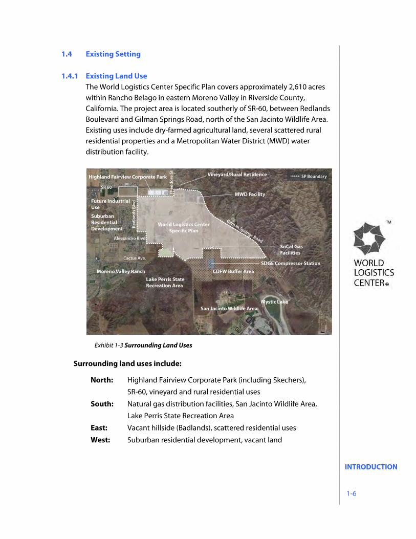
1.4.1 Existing Land Use The World Logistics Center Specific Plan covers approximately 2,610 acres within Rancho Belago in eastern Moreno Valley in Riverside County, California. The project area is located southerly of SR-60, between Redlands Boulevard and Gilman Springs Road, north of the San Jacinto Wildlife Area. Existing uses include dry-farmed agricultural land, several scattered rural residential properties and a Metropolitan Water District (MWD) water distribution facility.
Surrounding land uses include:
North: Highland Fairview Corporate Park (including Skechers),
SR-60, vineyard and rural residential uses
South: Natural gas distribution facilities, San Jacinto Wildlife Area,
Lake Perris State Recreation Area
East: Vacant hillside (Badlands), scattered residential uses
West: Suburban residential development, vacant land
Exhibit 1-3 Surrounding Land Uses
INTRODUCTION 1-7
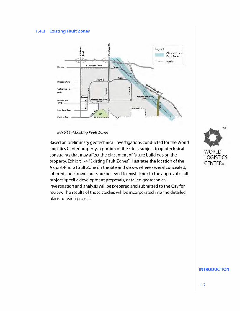
1.4.2 Existing Fault Zones
Based on preliminary geotechnical investigations conducted for the World Logistics Center property, a portion of the site is subject to geotechnical constraints that may affect the placement of future buildings on the property. Exhibit 1-4 “Existing Fault Zones” illustrates the location of the Alquist-Priolo Fault Zone on the site and shows where several concealed, inferred and known faults are believed to exist. Prior to the approval of all project-specific development proposals, detailed geotechnical investigation and analysis will be prepared and submitted to the City for review. The results of those studies will be incorporated into the detailed plans for each project.
Exhibit 1-4 Existing Fault Zones
LAND USE PLAN 2-1
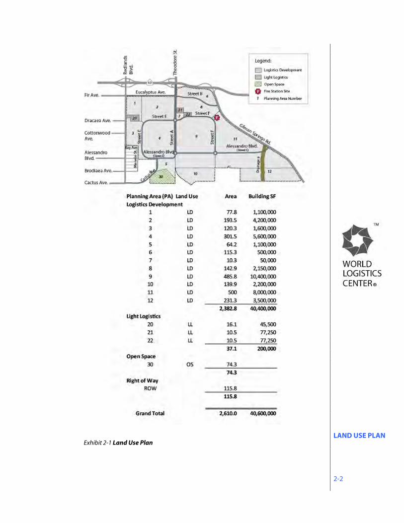
2.0 LAND USE PLAN 2.1 World Logistics Center Land Use Designations The World Logistics Center Specific Plan provides for the development of a master-planned project specifically designed to support logistics uses by incorporating landscape and architectural standards, project-wide criteria for streets, drainage, public infrastructure, lighting and signage, and project features responsive to the needs of the logistics industry. The Specific Plan includes a land use plan providing for three land use designations: Logistics Development (LD), Light Logistics (LL), and Open Space (OS). A Circulation Plan provides a roadway network that moves cars and trucks into and through the World Logistics Center in a safe, efficient manner. An Infrastructure Plan is included that addresses the current status of local infrastructure services such as water, sewer, storm drain, electricity and telephone/cable TV and outlines the backbone improvements necessary for these systems to serve the World Logistics Center project. Guidelines for landscaping and architectural design are provided to ensure that a distinct consistent aesthetic theme is realized throughout the project. Additionally, the Plan establishes an implementation program that provides the processes and procedures for the review and approval of project-specific development proposals, carrying out the purpose and intent of the Specific Plan. All of these elements function together to create a comprehensive development program to ensure that the World Logistics Center becomes the contemporary standard for logistics campus projects.
LAND USE PLAN 2-2
Exhibit 2-1 Land Use Plan
LAND USE PLAN 2-3
Land Use Designations:
Logistics Development - (LD) The LD designation provides for high-cube logistics warehouse uses consisting of buildings of 500,000 square feet or greater. Warehousing and logistics activities consistent with the storage, assembly and processing of manufactured goods and materials prior to their distribution to other facilities are permitted within this category along with facilities for the outdoor storage of trucks, trailers and shipping containers. Ancillary office, employee services and property management facilities are permitted in connection with primary uses. Development standards for the LD category are included in Section 2.2 of this Specific Plan.
Light Logistics - (LL) The LL designation provides for warehouse uses less than 500,000 square feet in size, self-storage and vehicle storage uses. Ancillary office, employee services and property management facilities are permitted in connection with primary uses. Development standards for the LL category are included in Section 2.3 of this Specific Plan.
Open Space - (OS) The OS designation identifies a 74.3 acre area in the southwestern portion of the site which is a portion of Mt. Russell. The intent of the OS designation is to preserve this area as a permanent Open Space. This area shall comply with the City of Moreno Valley Open Space Standards and permitted uses.
LAND USE PLAN 2-4
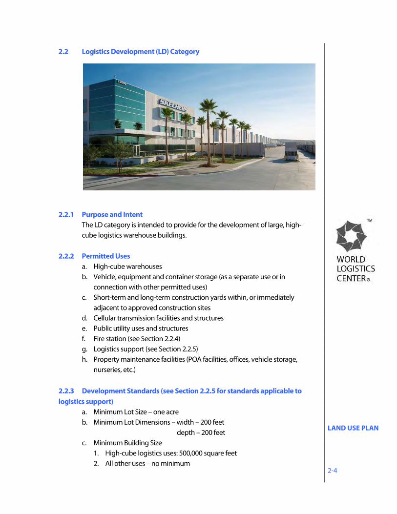
2.2 Logistics Development (LD) Category
2.2.1 Purpose and Intent
The LD category is intended to provide for the development of large, high-cube logistics warehouse buildings.
2.2.2 Permitted Uses a. High-cube warehouses b. Vehicle, equipment and container storage (as a separate use or in
connection with other permitted uses) c. Short-term and long-term construction yards within, or immediately
adjacent to approved construction sites d. Cellular transmission facilities and structures e. Public utility uses and structures f. Fire station (see Section 2.2.4) g. Logistics support (see Section 2.2.5) h. Property maintenance facilities (POA facilities, offices, vehicle storage,
nurseries, etc.) 2.2.3 Development Standards (see Section 2.2.5 for standards applicable to logistics support)
a. Minimum Lot Size – one acre b. Minimum Lot Dimensions – width – 200 feet depth – 200 feet c. Minimum Building Size
1. High-cube logistics uses: 500,000 square feet 2. All other uses – no minimum
LAND USE PLAN 2-5
d. Floor Area Ratio (FAR) 1. High-cube logistics uses – no minimum; 1.0 FAR maximum.
e. Building Height 1. Vehicle/container storage uses – maximum 25 feet 2. High-cube logistics uses – maximum 60 feet or 80 feet per Exhibit 5-3 3. Cell towers – refer to Municipal Code.
f. Building Setbacks (Minimum) 1. From any public street: 60 feet. 2. From other property lines: no minimum 3. From residentially occupied property within the WLC: all buildings shall
be set back a distance equal to or greater than the height of the proposed building.
4. From SJWA property: 400 feet (See Exhibit 4-16) 5. From residentially zoned property: 250 feet measured from the
City/County zoning boundary (See exhibits in Section 4.2.4) 6. From SDG&E Compressor Station buildings: No buildings shall be
located less than 1000 feet from existing buildings at the SDG&E Compressor Station. (See Exhibit 4-16)
g. Maximum Lot Coverage – None h. Landscape Coverage
1. High-cube logistics uses – 10% minimum 2. All other uses – no minimum 3. Landscape buffer - 20 feet minimum from street
i. Accessory Structure Size – no minimum, no maximum j. Accessory Structure Setbacks – same as primary buildings k. Legal nonconforming uses: the provisions of Municipal Code
Section 9.02.180 “Legal nonconforming uses, improvements and parcels” shall apply.
LAND USE PLAN 2-6
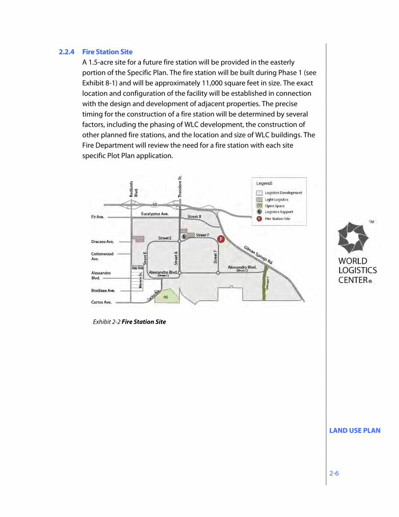
2.2.4 Fire Station Site A 1.5-acre site for a future fire station will be provided in the easterly portion of the Specific Plan. The fire station will be built during Phase 1 (see Exhibit 8-1) and will be approximately 11,000 square feet in size. The exact location and configuration of the facility will be established in connection with the design and development of adjacent properties. The precise timing for the construction of a fire station will be determined by several factors, including the phasing of WLC development, the construction of other planned fire stations, and the location and size of WLC buildings. The Fire Department will review the need for a fire station with each site specific Plot Plan application.
Exhibit 2-2 Fire Station Site
LAND USE PLAN 2-7
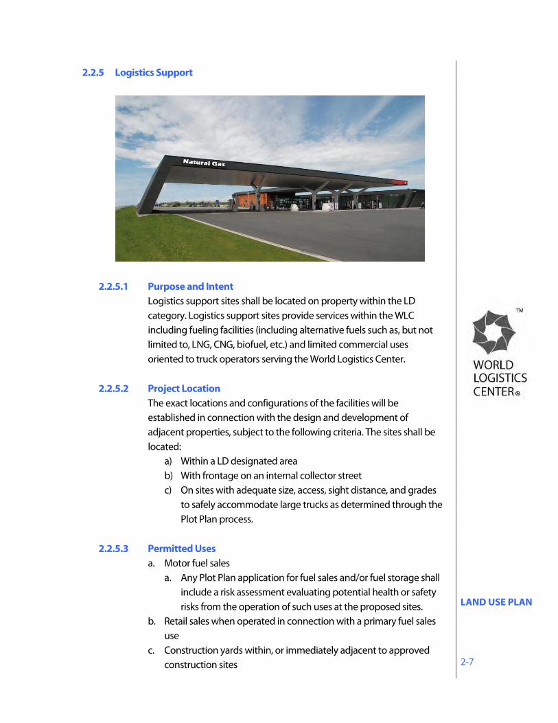
2.2.5 Logistics Support
2.2.5.1 Purpose and Intent Logistics support sites shall be located on property within the LD category. Logistics support sites provide services within the WLC including fueling facilities (including alternative fuels such as, but not limited to, LNG, CNG, biofuel, etc.) and limited commercial uses oriented to truck operators serving the World Logistics Center.
2.2.5.2 Project Location
The exact locations and configurations of the facilities will be established in connection with the design and development of adjacent properties, subject to the following criteria. The sites shall be located:
a) Within a LD designated area b) With frontage on an internal collector street c) On sites with adequate size, access, sight distance, and grades
to safely accommodate large trucks as determined through the Plot Plan process.
2.2.5.3 Permitted Uses
a. Motor fuel sales a. Any Plot Plan application for fuel sales and/or fuel storage shall
include a risk assessment evaluating potential health or safety risks from the operation of such uses at the proposed sites.
b. Retail sales when operated in connection with a primary fuel sales use
c. Construction yards within, or immediately adjacent to approved construction sites
LAND USE PLAN 2-8
d. Cellular transmission facilities and structures e. Public utility uses and structures
2.2.5.4 Prohibited Uses a. Vehicle service/maintenance/repairs/storage b. Drive-thru facilities c. Overnight truck parking d. Towing services
2.2.5.5 Development Standards
a. Minimum Lot Size – 1.0 acre b. Minimum Lot Dimension – width – 200 feet depth – 200 feet c. Building Size – no minimum, 3,000 sq. ft. maximum not including
canopy area d. Floor Area Ratio
1. No minimum; 1.0 FAR maximum. e. Building Height – 25 feet maximum f. Setbacks (Minimum):
1. 20 feet from all property lines except adjacent to any residential property where buildings shall be set back a distance equal to or greater than the height of the proposed building. 2. All fueling facilities shall be a minimum of 250 feet from any residentially occupied or zoned properties.
g. Maximum Lot Coverage – None h. Landscape Coverage - no minimum 1. Landscape Buffer – 20 feet minimum from street i. Canopies – Fueling areas shall be covered. j. Accessory Structure Size – no minimum, no maximum k. Accessory Structure Setbacks – same as primary buildings l. Prohibited Uses – 1. Vehicle service/ maintenance/ repairs/ storage 2. Drive-thru facilities 3. Overnight truck parking 4. Towing services
LAND USE PLAN 2-9
2.3 Light Logistics (LL) Category
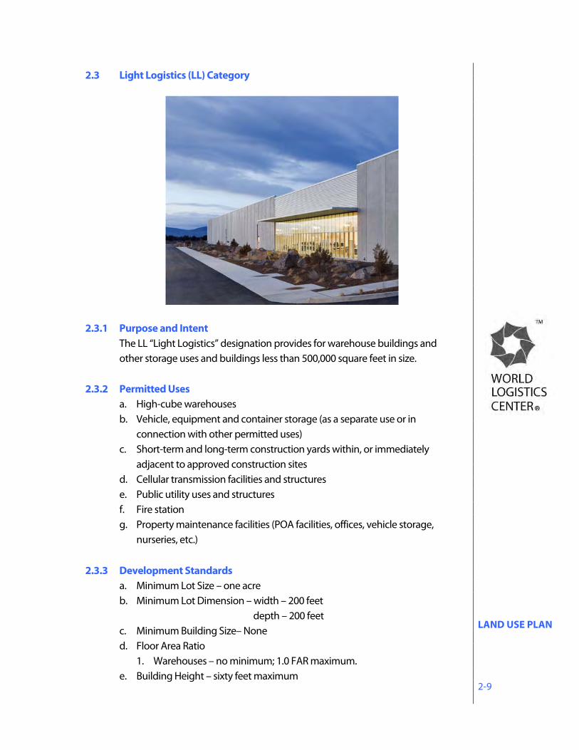
2.3.1 Purpose and Intent
The LL “Light Logistics” designation provides for warehouse buildings and other storage uses and buildings less than 500,000 square feet in size.
2.3.2 Permitted Uses
a. High-cube warehouses b. Vehicle, equipment and container storage (as a separate use or in
connection with other permitted uses) c. Short-term and long-term construction yards within, or immediately
adjacent to approved construction sites d. Cellular transmission facilities and structures e. Public utility uses and structures f. Fire station g. Property maintenance facilities (POA facilities, offices, vehicle storage,
nurseries, etc.) 2.3.3 Development Standards
a. Minimum Lot Size – one acre b. Minimum Lot Dimension – width – 200 feet depth – 200 feet c. Minimum Building Size– None d. Floor Area Ratio
1. Warehouses – no minimum; 1.0 FAR maximum. e. Building Height – sixty feet maximum
LAND USE PLAN 2-10
f. Building Setbacks (Minimum) 1. From any public street: twenty feet. 2. From other property lines: no minimum 3. From residentially occupied property within the WLC: all buildings shall
be set back a distance equal to or greater than the height of the proposed building.
4. From residentially zoned property: 250 feet measured from the City/County zoning boundary (See exhibits in Section 4.2.4)
5. Designated emergency access drives and employee/visitor parking are permitted in all setback areas.
g. Maximum Lot Coverage – None h. Landscape Coverage - No Minimum 1. Landscape buffer – 20 feet minimum from street i. Accessory Structure Size – no minimum, no maximum j. Accessory Structure Setbacks – same as primary buildings k. Legal nonconforming uses - the provisions of Municipal Code Section
9.02.180 “Legal nonconforming uses, improvements and parcels” shall apply.
LAND USE PLAN 2-11
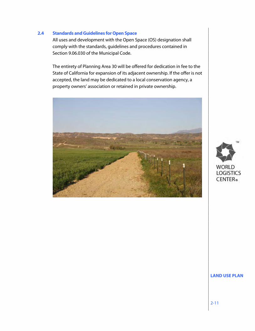
2.4 Standards and Guidelines for Open Space All uses and development with the Open Space (OS) designation shall comply with the standards, guidelines and procedures contained in Section 9.06.030 of the Municipal Code. The entirety of Planning Area 30 will be offered for dedication in fee to the State of California for expansion of its adjacent ownership. If the offer is not accepted, the land may be dedicated to a local conservation agency, a property owners’ association or retained in private ownership.
LAND USE PLAN 2-12
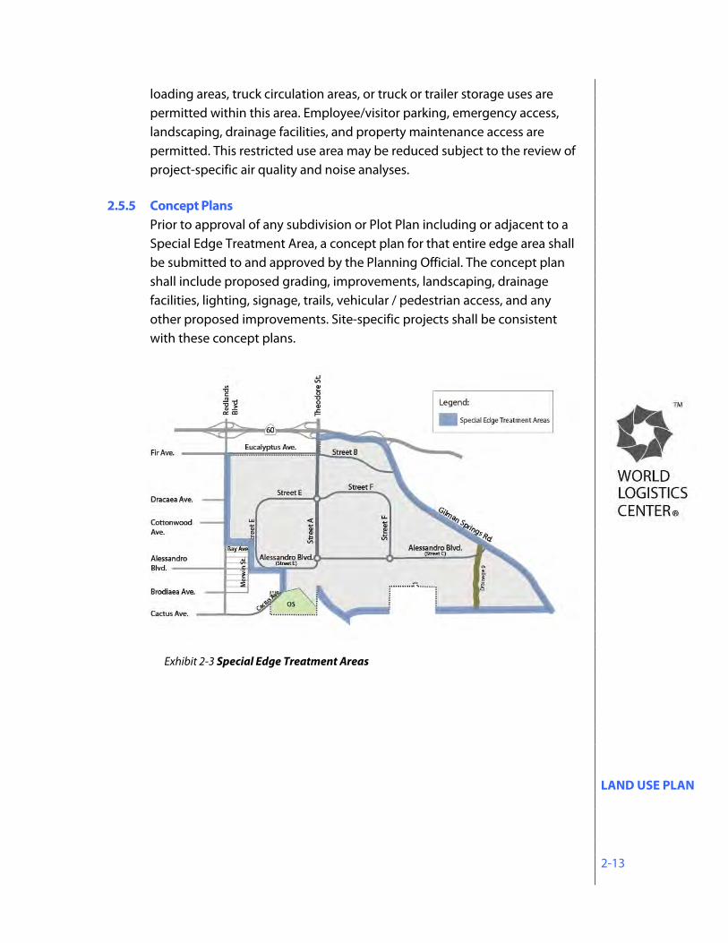
2.5 Special Edge Treatment Areas The Specific Plan includes three designated areas where special setbacks, facilities, grading and landscaping will be provided to create special edge treatment areas between the World Logistics Center and adjacent, existing land uses. These edge areas are shown on Exhibit 2-3 and detailed cross sections are shown in Section 4.2.4.
2.5.1 Western Edge The Western edge is adjacent to residentially-zoned property. This edge will feature a restricted use area in which no buildings, truck courts, loading areas, truck circulation areas, or truck or trailer storage uses are permitted. Employee/visitor parking, emergency access, landscaping, drainage facilities, and property maintenance access are permitted in this area. The restricted use area will be at least 250 feet from any residential zoning boundary.
2.5.2 SR-60 Edge
The SR-60 edge through the WLC will continue the general design established with the Highland Fairview Corporate Park project immediately to the west. Similar to the HFCP project, future development areas within the WLC will be lower than the freeway, with landscaped slopes providing screening of adjacent buildings and circulation areas. To ensure a consistent appearance of this edge, the landscape treatment of these slopes will continue the design and plant palette utilized at the HFCP project.
2.5.3 SJWA Edge
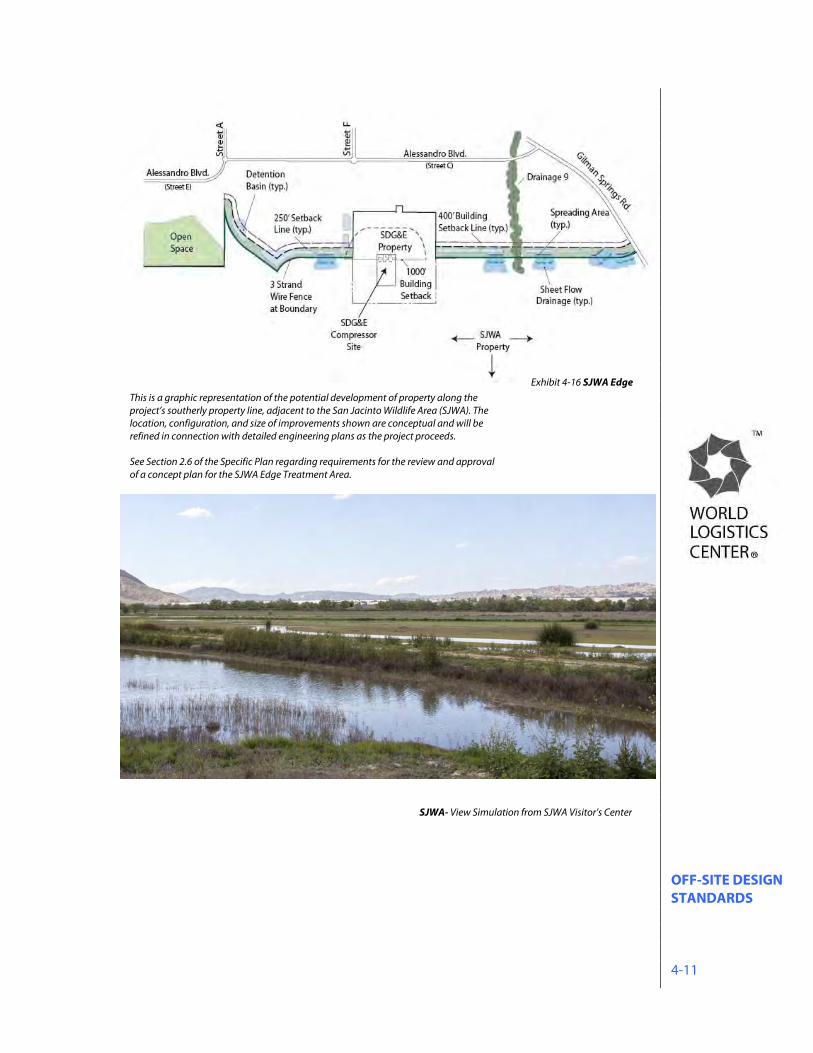
The San Jacinto Wildlife Area (SJWA) edge is along the southerly boundary of Planning Areas 10 and 12 (See Exhibit 2-1) and adjacent to state-owned open space currently in agricultural use. This edge will feature a restricted use area of at least 250 feet from these state-owned properties. No buildings, truck courts, loading areas, employee/visitor parking, truck circulation areas, or truck or trailer storage uses are permitted within this area. Emergency access, landscaping, drainage facilities, and property maintenance access are permitted. In addition to this 250 foot restricted use area, additional setback will be provided such that all buildings are a minimum of 400 feet from the SJWA boundary.
2.5.4 Gilman Springs Road Edge
The Gilman Springs Road edge will feature a restricted use area of at least 250 feet from any residential zoning boundary. No buildings, truck courts,
LAND USE PLAN 2-13
loading areas, truck circulation areas, or truck or trailer storage uses are permitted within this area. Employee/visitor parking, emergency access, landscaping, drainage facilities, and property maintenance access are permitted. This restricted use area may be reduced subject to the review of project-specific air quality and noise analyses.
2.5.5 Concept Plans
Prior to approval of any subdivision or Plot Plan including or adjacent to a Special Edge Treatment Area, a concept plan for that entire edge area shall be submitted to and approved by the Planning Official. The concept plan shall include proposed grading, improvements, landscaping, drainage facilities, lighting, signage, trails, vehicular / pedestrian access, and any other proposed improvements. Site-specific projects shall be consistent with these concept plans.
Exhibit 2-3 Special Edge Treatment Areas
INFRASTRUCTURE PLAN 3-1
3.0 INFRASTRUCTURE PLAN The Infrastructure Plan serves as a guide for the development of detailed plans for roadways, domestic water, wastewater, storm water and utilities that will serve the Specific Plan area. The conceptual infrastructure plans generally identify the location of infrastructure facilities within the project. Subsequent subdivisions and site development plans will establish the exact size and location of all such facilities.
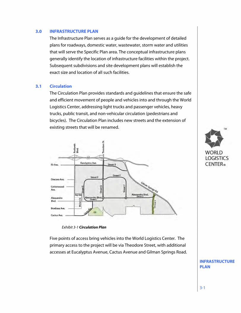
3.1 Circulation The Circulation Plan provides standards and guidelines that ensure the safe and efficient movement of people and vehicles into and through the World Logistics Center, addressing light trucks and passenger vehicles, heavy trucks, public transit, and non-vehicular circulation (pedestrians and bicycles). The Circulation Plan includes new streets and the extension of existing streets that will be renamed.
Five points of access bring vehicles into the World Logistics Center. The primary access to the project will be via Theodore Street, with additional accesses at Eucalyptus Avenue, Cactus Avenue and Gilman Springs Road.
Exhibit 3-1 Circulation Plan
INFRASTRUCTURE PLAN 3-2
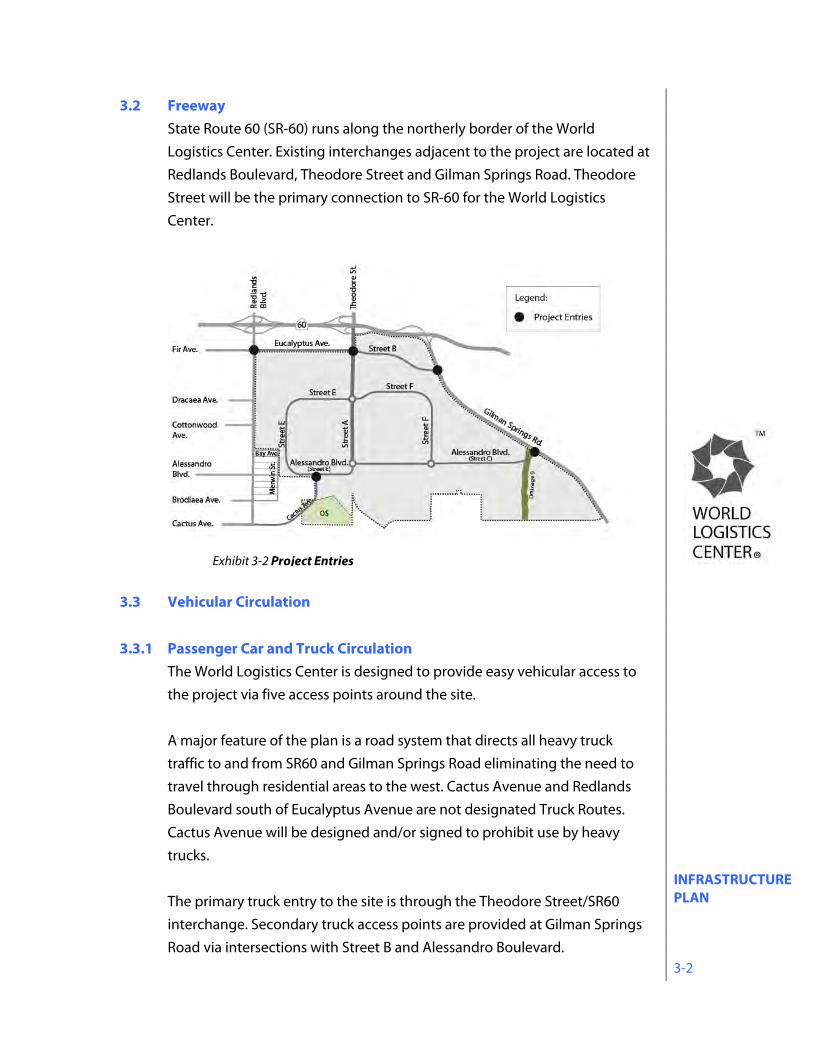
3.2 Freeway State Route 60 (SR-60) runs along the northerly border of the World Logistics Center. Existing interchanges adjacent to the project are located at Redlands Boulevard, Theodore Street and Gilman Springs Road. Theodore Street will be the primary connection to SR-60 for the World Logistics Center.
3.3 Vehicular Circulation
3.3.1 Passenger Car and Truck Circulation The World Logistics Center is designed to provide easy vehicular access to the project via five access points around the site. A major feature of the plan is a road system that directs all heavy truck traffic to and from SR60 and Gilman Springs Road eliminating the need to travel through residential areas to the west. Cactus Avenue and Redlands Boulevard south of Eucalyptus Avenue are not designated Truck Routes. Cactus Avenue will be designed and/or signed to prohibit use by heavy trucks. The primary truck entry to the site is through the Theodore Street/SR60 interchange. Secondary truck access points are provided at Gilman Springs Road via intersections with Street B and Alessandro Boulevard.
Exhibit 3-2 Project Entries
INFRASTRUCTURE PLAN 3-3
Access for cars and light/medium trucks is provided via the extension of Cactus Avenue in the southwest portion of the project. No heavy trucks are allowed to use this access. Redlands Boulevard south of Eucalyptus Avenue allows only passenger vehicle and light/medium truck access as it is not a City-designated truck route. Alessandro Boulevard is a historic roadway (per Resolution CPAB 88-2) and is subject to Special Regulations contained in Section 12.9 of this Specific Plan.
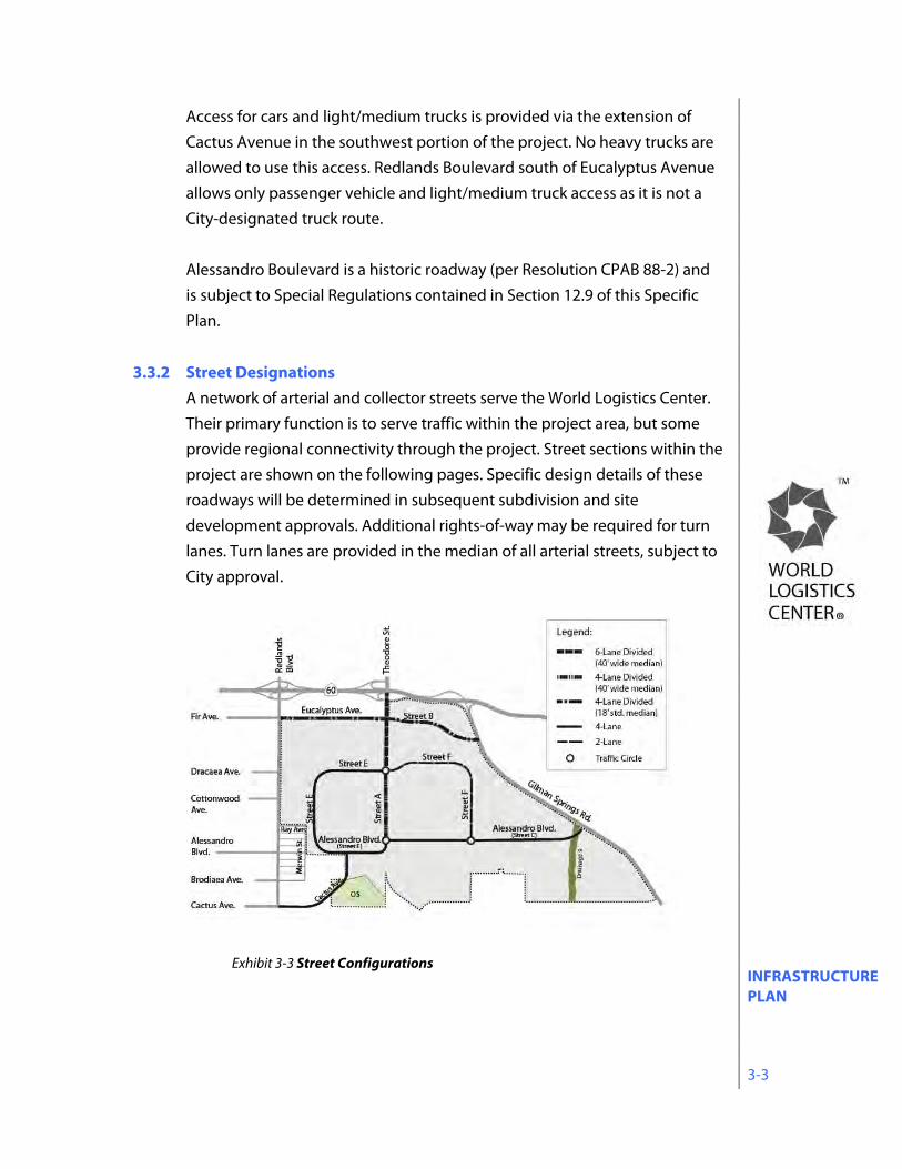
3.3.2 Street Designations A network of arterial and collector streets serve the World Logistics Center. Their primary function is to serve traffic within the project area, but some provide regional connectivity through the project. Street sections within the project are shown on the following pages. Specific design details of these roadways will be determined in subsequent subdivision and site development approvals. Additional rights-of-way may be required for turn lanes. Turn lanes are provided in the median of all arterial streets, subject to City approval.
Exhibit 3-3 Street Configurations
INFRASTRUCTURE PLAN 3-4
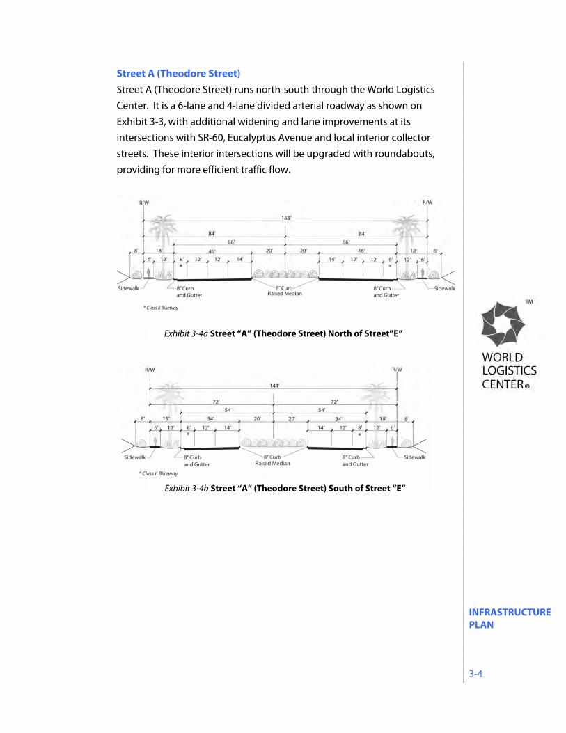
Street A (Theodore Street) Street A (Theodore Street) runs north-south through the World Logistics Center. It is a 6-lane and 4-lane divided arterial roadway as shown on Exhibit 3-3, with additional widening and lane improvements at its intersections with SR-60, Eucalyptus Avenue and local interior collector streets. These interior intersections will be upgraded with roundabouts, providing for more efficient traffic flow.
Exhibit 3-4a Street “A” (Theodore Street) North of Street”E”
Exhibit 3-4b Street “A” (Theodore Street) South of Street “E”
INFRASTRUCTURE PLAN 3-5
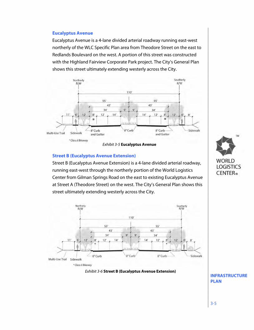
Eucalyptus Avenue Eucalyptus Avenue is a 4-lane divided arterial roadway running east-west northerly of the WLC Specific Plan area from Theodore Street on the east to Redlands Boulevard on the west. A portion of this street was constructed with the Highland Fairview Corporate Park project. The City’s General Plan shows this street ultimately extending westerly across the City.
Street B (Eucalyptus Avenue Extension) Street B (Eucalyptus Avenue Extension) is a 4-lane divided arterial roadway, running east-west through the northerly portion of the World Logistics Center from Gilman Springs Road on the east to existing Eucalyptus Avenue at Street A (Theodore Street) on the west. The City’s General Plan shows this street ultimately extending westerly across the City.
Exhibit 3-6 Street B (Eucalyptus Avenue Extension)
Exhibit 3-5 Eucalyptus Avenue

INFRASTRUCTURE PLAN 3-6
Street E Street E is a 4-lane undivided arterial roadway providing direct access to development areas in the westerly portion of the project. A roundabout is planned at its intersection with Street A. Design details of this roadway will be determined by subsequent subdivision and site development approvals.
Alessandro Boulevard Alessandro Boulevard is a 4-lane undivided roadway running east-west through the World Logistics Center, from Gilman Springs Road to Cactus Avenue. This roadway is a City-designated historic roadway (Resolution CPAB 88-2) and is subject to Special Regulations contained in Section 12.9 of this Specific Plan. Vehicular access will be prohibited on a portion of Alessandro Boulevard, east of Merwin Street in order to reduce through traffic and associated impacts on the residential portion of Alessandro Boulevard. Roundabouts are planned with its intersection with Street A and Street F.
Exhibit 3-7 Street E
Exhibit 3-8 Alessandro Boulevard
Note: See special regulations applicable to Alessandro Boulevard in Section 12.9 of the Specific Plan
INFRASTRUCTURE PLAN 3-7
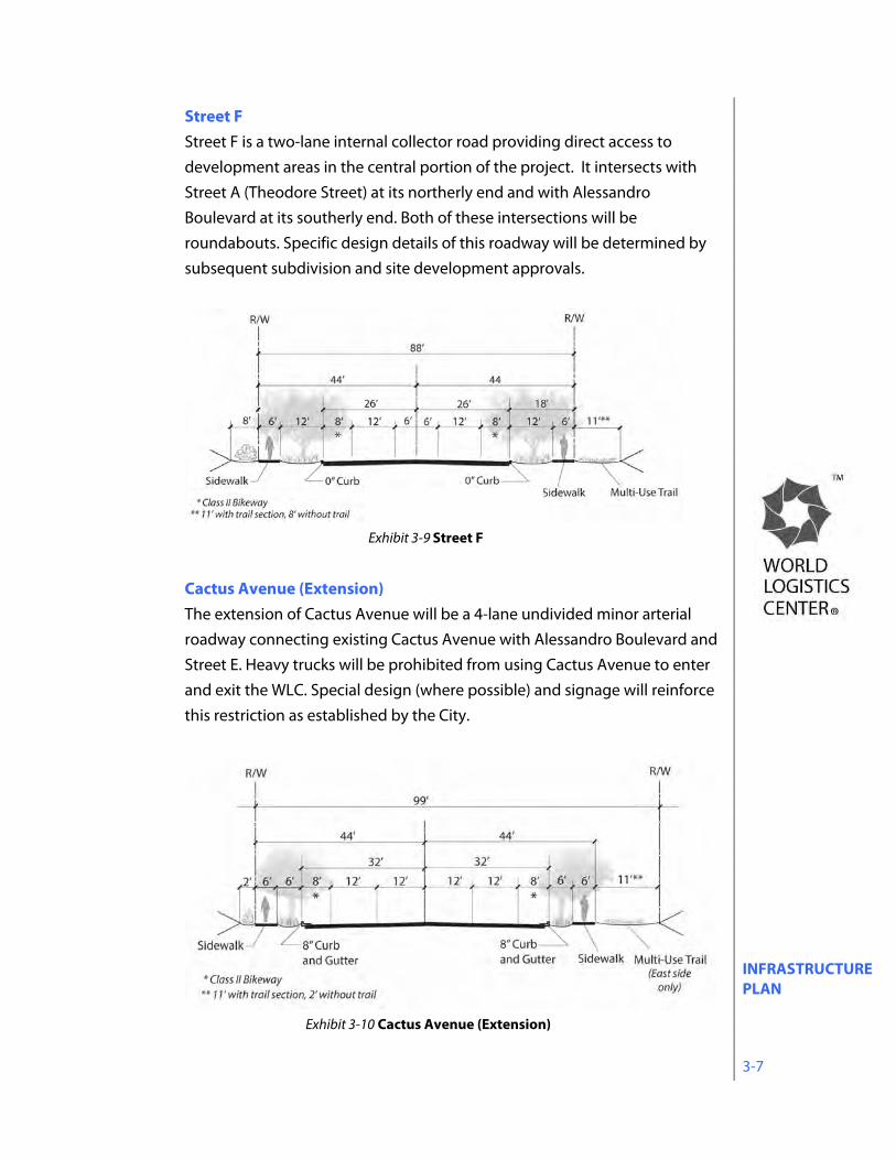
Street F Street F is a two-lane internal collector road providing direct access to development areas in the central portion of the project. It intersects with Street A (Theodore Street) at its northerly end and with Alessandro Boulevard at its southerly end. Both of these intersections will be roundabouts. Specific design details of this roadway will be determined by subsequent subdivision and site development approvals.
Cactus Avenue (Extension) The extension of Cactus Avenue will be a 4-lane undivided minor arterial roadway connecting existing Cactus Avenue with Alessandro Boulevard and Street E. Heavy trucks will be prohibited from using Cactus Avenue to enter and exit the WLC. Special design (where possible) and signage will reinforce this restriction as established by the City.
Exhibit 3-9 Street F
Exhibit 3-10 Cactus Avenue (Extension)
INFRASTRUCTURE PLAN 3-8
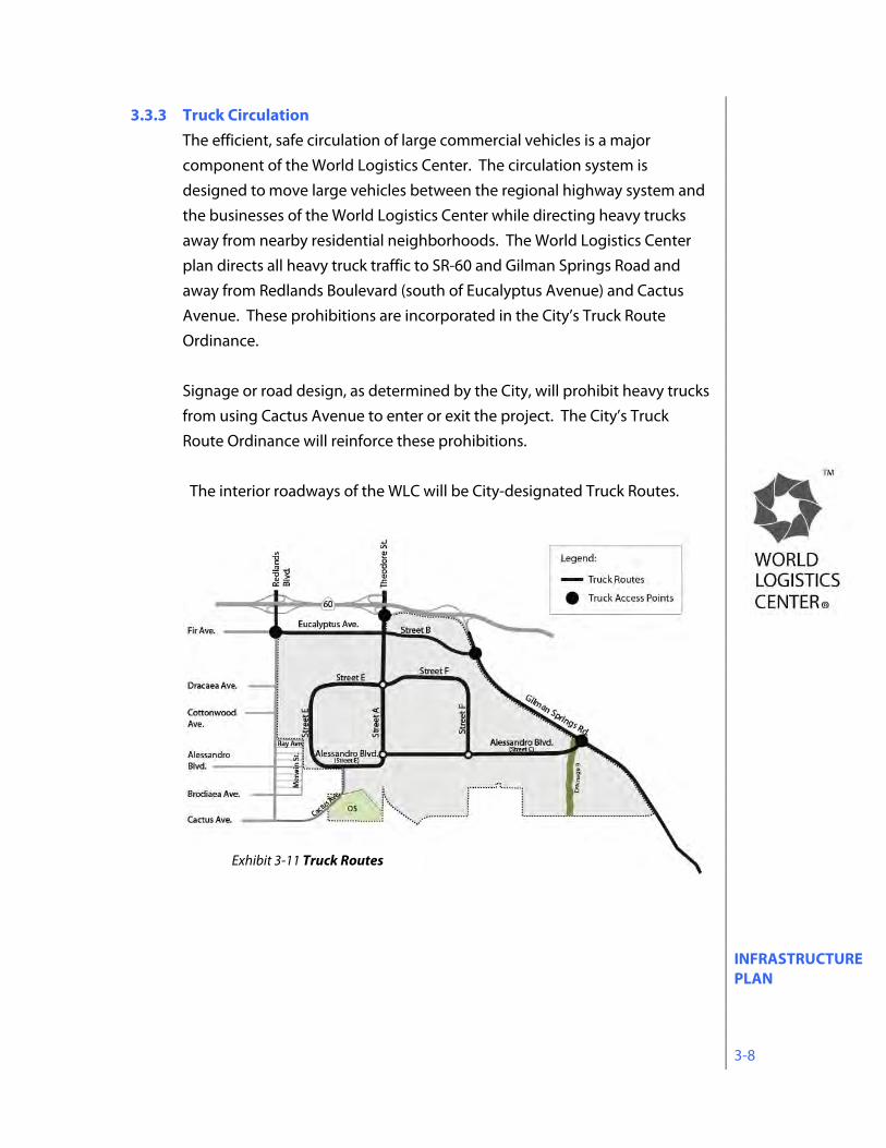
3.3.3 Truck Circulation The efficient, safe circulation of large commercial vehicles is a major component of the World Logistics Center. The circulation system is designed to move large vehicles between the regional highway system and the businesses of the World Logistics Center while directing heavy trucks away from nearby residential neighborhoods. The World Logistics Center plan directs all heavy truck traffic to SR-60 and Gilman Springs Road and away from Redlands Boulevard (south of Eucalyptus Avenue) and Cactus Avenue. These prohibitions are incorporated in the City’s Truck Route Ordinance. Signage or road design, as determined by the City, will prohibit heavy trucks from using Cactus Avenue to enter or exit the project. The City’s Truck Route Ordinance will reinforce these prohibitions. The interior roadways of the WLC will be City-designated Truck Routes.
Exhibit 3-11 Truck Routes
INFRASTRUCTURE PLAN 3-9
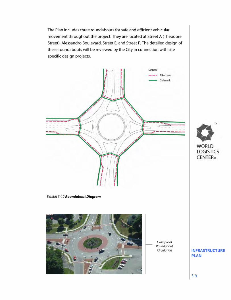
The Plan includes three roundabouts for safe and efficient vehicular movement throughout the project. They are located at Street A (Theodore Street), Alessandro Boulevard, Street E, and Street F. The detailed design of these roundabouts will be reviewed by the City in connection with site specific design projects.
Exhibit 3-12 Roundabout Diagram
Example of Roundabout Circulation
INFRASTRUCTURE PLAN 3-10
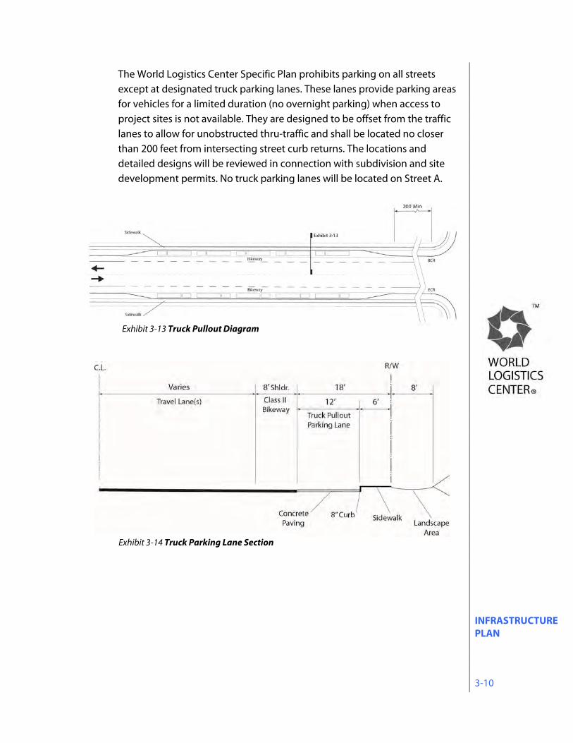
The World Logistics Center Specific Plan prohibits parking on all streets except at designated truck parking lanes. These lanes provide parking areas for vehicles for a limited duration (no overnight parking) when access to project sites is not available. They are designed to be offset from the traffic lanes to allow for unobstructed thru-traffic and shall be located no closer than 200 feet from intersecting street curb returns. The locations and detailed designs will be reviewed in connection with subdivision and site development permits. No truck parking lanes will be located on Street A.
Exhibit 3-13 Truck Pullout Diagram
Exhibit 3-14 Truck Parking Lane Section
INFRASTRUCTURE PLAN 3-11
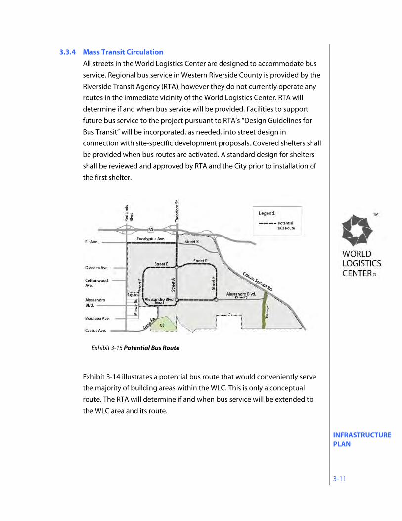
3.3.4 Mass Transit Circulation All streets in the World Logistics Center are designed to accommodate bus service. Regional bus service in Western Riverside County is provided by the Riverside Transit Agency (RTA), however they do not currently operate any routes in the immediate vicinity of the World Logistics Center. RTA will determine if and when bus service will be provided. Facilities to support future bus service to the project pursuant to RTA’s “Design Guidelines for Bus Transit” will be incorporated, as needed, into street design in connection with site-specific development proposals. Covered shelters shall be provided when bus routes are activated. A standard design for shelters shall be reviewed and approved by RTA and the City prior to installation of the first shelter.
Exhibit 3-14 illustrates a potential bus route that would conveniently serve the majority of building areas within the WLC. This is only a conceptual route. The RTA will determine if and when bus service will be extended to the WLC area and its route.
Exhibit 3-15 Potential Bus Route
INFRASTRUCTURE PLAN 3-12
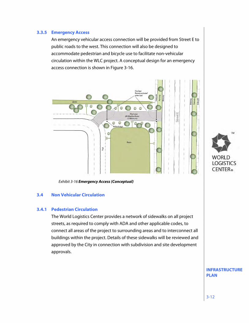
3.3.5 Emergency Access An emergency vehicular access connection will be provided from Street E to public roads to the west. This connection will also be designed to accommodate pedestrian and bicycle use to facilitate non-vehicular circulation within the WLC project. A conceptual design for an emergency access connection is shown in Figure 3-16.
3.4 Non Vehicular Circulation 3.4.1 Pedestrian Circulation
The World Logistics Center provides a network of sidewalks on all project streets, as required to comply with ADA and other applicable codes, to connect all areas of the project to surrounding areas and to interconnect all buildings within the project. Details of these sidewalks will be reviewed and approved by the City in connection with subdivision and site development approvals.
Exhibit 3-16 Emergency Access (Conceptual)
INFRASTRUCTURE PLAN 3-13
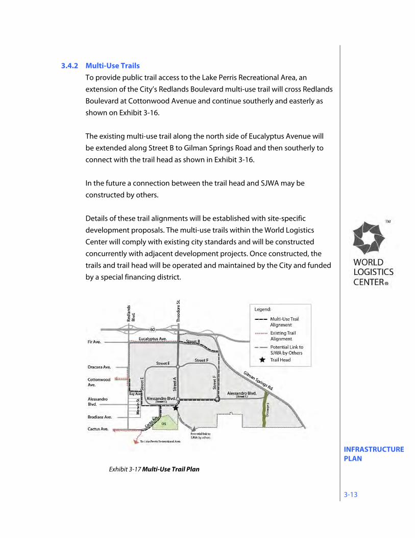
3.4.2 Multi-Use Trails To provide public trail access to the Lake Perris Recreational Area, an extension of the City’s Redlands Boulevard multi-use trail will cross Redlands Boulevard at Cottonwood Avenue and continue southerly and easterly as shown on Exhibit 3-16. The existing multi-use trail along the north side of Eucalyptus Avenue will be extended along Street B to Gilman Springs Road and then southerly to connect with the trail head as shown in Exhibit 3-16. In the future a connection between the trail head and SJWA may be constructed by others. Details of these trail alignments will be established with site-specific development proposals. The multi-use trails within the World Logistics Center will comply with existing city standards and will be constructed concurrently with adjacent development projects. Once constructed, the trails and trail head will be operated and maintained by the City and funded by a special financing district.
Exhibit 3-17 Multi-Use Trail Plan
INFRASTRUCTURE PLAN 3-14
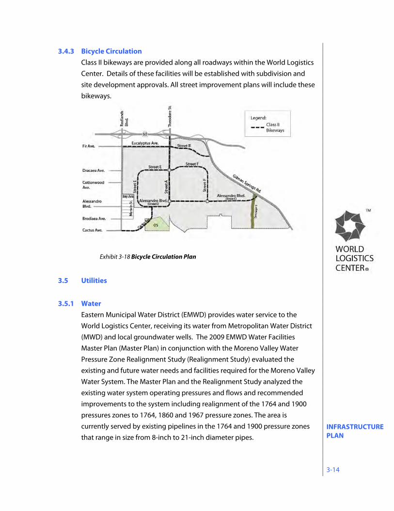
3.4.3 Bicycle Circulation Class II bikeways are provided along all roadways within the World Logistics Center. Details of these facilities will be established with subdivision and site development approvals. All street improvement plans will include these bikeways.
3.5 Utilities 3.5.1 Water
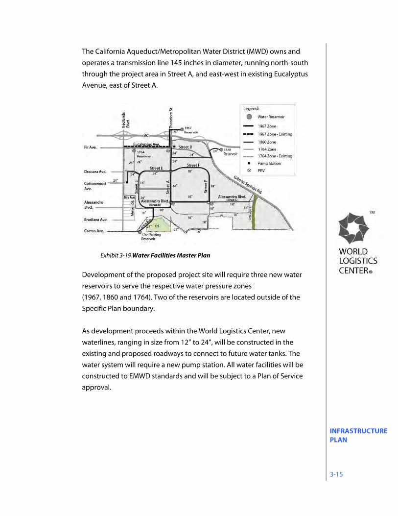
Eastern Municipal Water District (EMWD) provides water service to the World Logistics Center, receiving its water from Metropolitan Water District (MWD) and local groundwater wells. The 2009 EMWD Water Facilities Master Plan (Master Plan) in conjunction with the Moreno Valley Water Pressure Zone Realignment Study (Realignment Study) evaluated the existing and future water needs and facilities required for the Moreno Valley Water System. The Master Plan and the Realignment Study analyzed the existing water system operating pressures and flows and recommended improvements to the system including realignment of the 1764 and 1900 pressures zones to 1764, 1860 and 1967 pressure zones. The area is currently served by existing pipelines in the 1764 and 1900 pressure zones that range in size from 8-inch to 21-inch diameter pipes.
Exhibit 3-18 Bicycle Circulation Plan
INFRASTRUCTURE PLAN 3-15
The California Aqueduct/Metropolitan Water District (MWD) owns and operates a transmission line 145 inches in diameter, running north-south through the project area in Street A, and east-west in existing Eucalyptus Avenue, east of Street A.
Development of the proposed project site will require three new water reservoirs to serve the respective water pressure zones (1967, 1860 and 1764). Two of the reservoirs are located outside of the Specific Plan boundary. As development proceeds within the World Logistics Center, new waterlines, ranging in size from 12” to 24”, will be constructed in the existing and proposed roadways to connect to future water tanks. The water system will require a new pump station. All water facilities will be constructed to EMWD standards and will be subject to a Plan of Service approval.
Exhibit 3-19 Water Facilities Master Plan
INFRASTRUCTURE PLAN 3-16
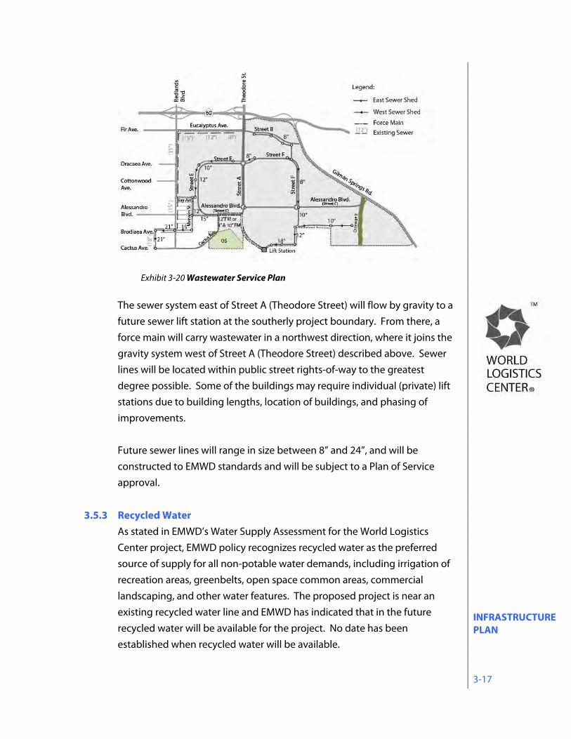
3.5.2 Sewer Eastern Municipal Water District (EMWD) provides wastewater service to the World Logistics Center area. Wastewater generated from the World Logistics Center area will be treated at EMWD’s Moreno Valley Regional Water Reclamation Facility (MVRWRF). The MVRWRF, located in the southwestern portion of the City near Kitching Street and Mariposa Avenue, has the capacity to treat 16 million gallons per day (MGD) of wastewater, which will accommodate the needs of the WLC project. The primary trunk sewer line serving the World Logistics Center area is located in Redlands Boulevard. This trunk sewer line continues in a southerly direction in Cactus Avenue, JFK Drive, Iris Avenue and Lasselle Streets conveying wastewater to the MVRWRF. The proposed sewer in Street A (Theodore Street) and all lines to the west of Theodore Street form a gravity system and run generally southwest to a point of connection at Brodiaea Avenue and Redlands Boulevard. As demand requires, the existing segment of sewer in Brodiaea Avenue and Wilmot Street, west of Redlands Boulevard, will be upsized from a 15” to a 33” and 36” line respectively.
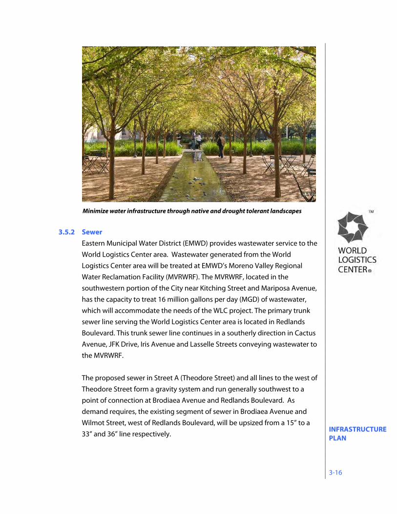
Minimize water infrastructure through native and drought tolerant landscapes
INFRASTRUCTURE PLAN 3-17
The sewer system east of Street A (Theodore Street) will flow by gravity to a future sewer lift station at the southerly project boundary. From there, a force main will carry wastewater in a northwest direction, where it joins the gravity system west of Street A (Theodore Street) described above. Sewer lines will be located within public street rights-of-way to the greatest degree possible. Some of the buildings may require individual (private) lift stations due to building lengths, location of buildings, and phasing of improvements. Future sewer lines will range in size between 8” and 24”, and will be constructed to EMWD standards and will be subject to a Plan of Service approval.
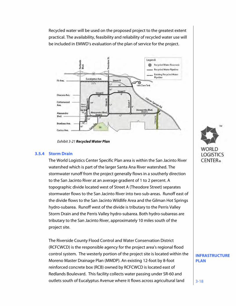
3.5.3 Recycled Water As stated in EMWD’s Water Supply Assessment for the World Logistics Center project, EMWD policy recognizes recycled water as the preferred source of supply for all non-potable water demands, including irrigation of recreation areas, greenbelts, open space common areas, commercial landscaping, and other water features. The proposed project is near an existing recycled water line and EMWD has indicated that in the future recycled water will be available for the project. No date has been established when recycled water will be available.
Exhibit 3-20 Wastewater Service Plan
INFRASTRUCTURE PLAN 3-18
Recycled water will be used on the proposed project to the greatest extent practical. The availability, feasibility and reliability of recycled water use will be included in EMWD’s evaluation of the plan of service for the project.
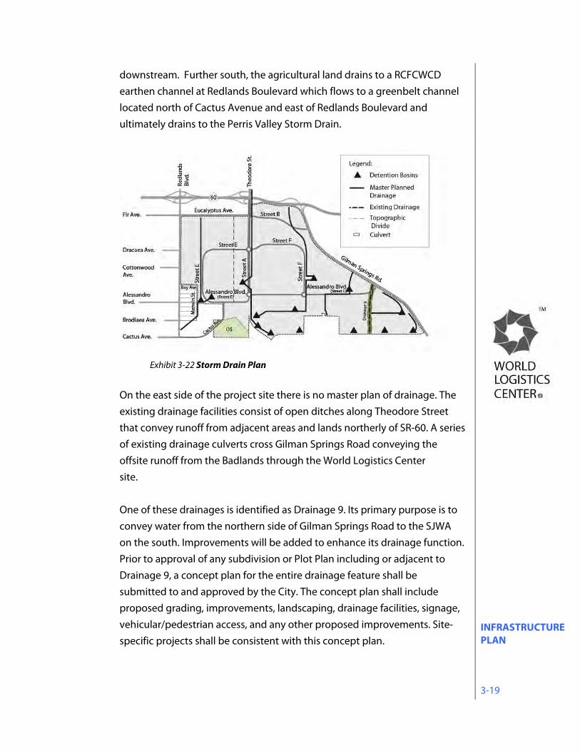
3.5.4 Storm Drain
The World Logistics Center Specific Plan area is within the San Jacinto River watershed which is part of the larger Santa Ana River watershed. The stormwater runoff from the project generally flows in a southerly direction to the San Jacinto River at an average gradient of 1 to 2 percent. A topographic divide located west of Street A (Theodore Street) separates stormwater flows to the San Jacinto River into two sub-areas. Runoff east of the divide flows to the San Jacinto Wildlife Area and the Gilman Hot Springs hydro-subarea. Runoff west of the divide is tributary to the Perris Valley Storm Drain and the Perris Valley hydro-subarea. Both hydro-subareas are tributary to the San Jacinto River, approximately 10 miles south of the project site. The Riverside County Flood Control and Water Conservation District (RCFCWCD) is the responsible agency for the project area’s regional flood control system. The westerly portion of the project site is located within the Moreno Master Drainage Plan (MMDP). An existing 12-foot by 8-foot reinforced concrete box (RCB) owned by RCFCWCD is located east of Redlands Boulevard. This facility collects water passing under SR-60 and outlets south of Eucalyptus Avenue where it flows across agricultural land
Exhibit 3-21 Recycled Water Plan
INFRASTRUCTURE PLAN 3-19
downstream. Further south, the agricultural land drains to a RCFCWCD earthen channel at Redlands Boulevard which flows to a greenbelt channel located north of Cactus Avenue and east of Redlands Boulevard and ultimately drains to the Perris Valley Storm Drain.
On the east side of the project site there is no master plan of drainage. The existing drainage facilities consist of open ditches along Theodore Street that convey runoff from adjacent areas and lands northerly of SR-60. A series of existing drainage culverts cross Gilman Springs Road conveying the offsite runoff from the Badlands through the World Logistics Center site. One of these drainages is identified as Drainage 9. Its primary purpose is to convey water from the northern side of Gilman Springs Road to the SJWA on the south. Improvements will be added to enhance its drainage function. Prior to approval of any subdivision or Plot Plan including or adjacent to Drainage 9, a concept plan for the entire drainage feature shall be submitted to and approved by the City. The concept plan shall include proposed grading, improvements, landscaping, drainage facilities, signage, vehicular/pedestrian access, and any other proposed improvements. Site-specific projects shall be consistent with this concept plan.
Exhibit 3-22 Storm Drain Plan
INFRASTRUCTURE PLAN 3-20
Based on the latest Flood Insurance Rate Map (FIRM) published by the Federal Emergency Management Agency (FEMA), the project site is not located within a 100-year floodplain. A system of underground drainage lines and detention basins will convey the stormwater runoff and manage the increased flow due to the proposed development. At each stage of development, the peak flows at downstream discharge points at the southerly project boundary will not exceed the peak flows for the existing condition. Along the boundary of the San Jacinto Wildlife Area, concentrated flows released from detention basins will be spread to mimic existing sheet flow patterns.
3.5.5 Utility Conditions
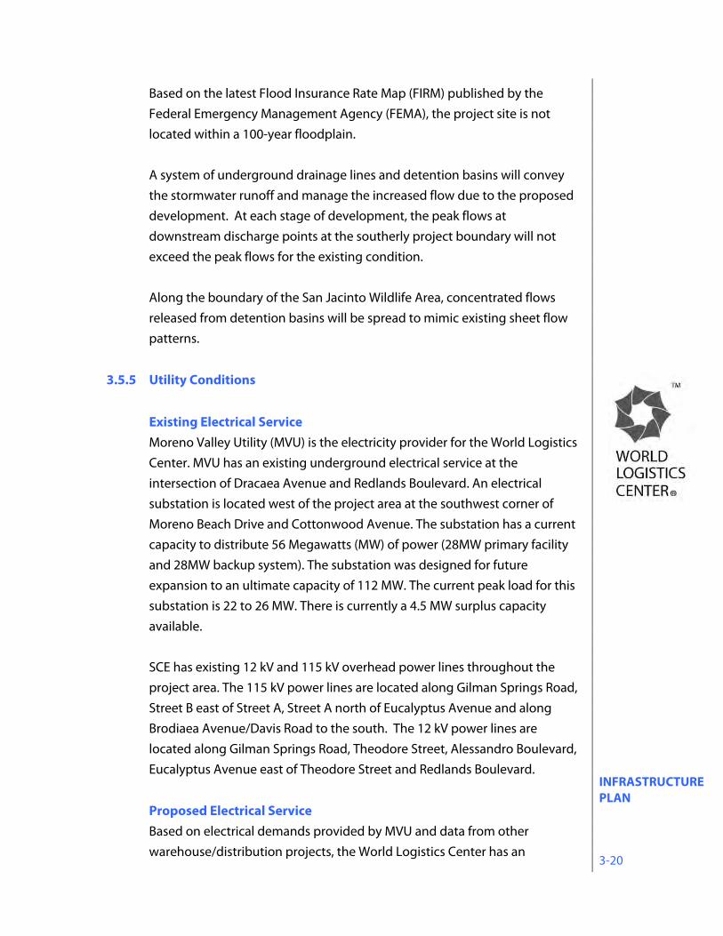
Existing Electrical Service Moreno Valley Utility (MVU) is the electricity provider for the World Logistics Center. MVU has an existing underground electrical service at the intersection of Dracaea Avenue and Redlands Boulevard. An electrical substation is located west of the project area at the southwest corner of Moreno Beach Drive and Cottonwood Avenue. The substation has a current capacity to distribute 56 Megawatts (MW) of power (28MW primary facility and 28MW backup system). The substation was designed for future expansion to an ultimate capacity of 112 MW. The current peak load for this substation is 22 to 26 MW. There is currently a 4.5 MW surplus capacity available. SCE has existing 12 kV and 115 kV overhead power lines throughout the project area. The 115 kV power lines are located along Gilman Springs Road, Street B east of Street A, Street A north of Eucalyptus Avenue and along Brodiaea Avenue/Davis Road to the south. The 12 kV power lines are located along Gilman Springs Road, Theodore Street, Alessandro Boulevard, Eucalyptus Avenue east of Theodore Street and Redlands Boulevard.
Proposed Electrical Service Based on electrical demands provided by MVU and data from other warehouse/distribution projects, the World Logistics Center has an
INFRASTRUCTURE PLAN 3-21
estimated peak electrical demand of 68 MW. As development proceeds, the existing electrical substation located at the southwest corner of Moreno Beach Drive and Cottonwood Avenue will be expanded to its planned 112 MW capacity. A new substation will be built within the World Logistics Center area to meet the project’s electrical demand at build-out. All MVU primary distribution conductors within the project will be installed in underground conduit and vaults in the public street right-of-way or easements as a joint trench with telephone, cable TV and natural gas. Any SCE overhead power pole lines, less than 115kV, that need to be relocated to develop the project will be placed in underground conduits and vaults. SCE facilities 115kv or greater will remain as overhead lines.
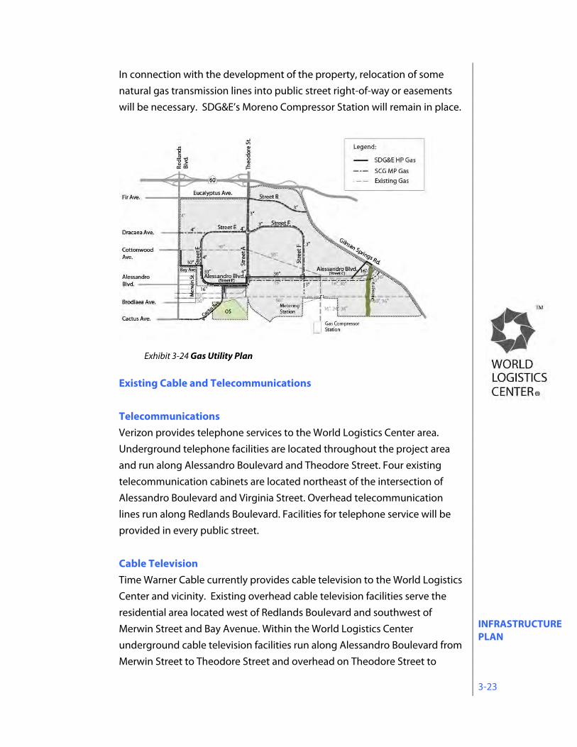
Existing Natural Gas Southern California Gas Company (SCGC) is the natural gas provider for the World Logistics Center. A 4” medium pressure service line runs in Redlands Boulevard. Low pressure facilities serve the residential area located west of Redlands Boulevard and southwest of Merwin Street and Bay Avenue. Throughout the World Logistics Center, natural gas is transmitted through SDG&E underground pipelines serving the Southern California region that range in size from 16 inches to 36 inches. Two 30” diameter transmission pipelines that run in an east-west direction are located north and south of
Exhibit 3-23 Electrical Utility Plan
INFRASTRUCTURE PLAN 3-22
Alessandro Boulevard. Three transmission pipelines, 16”, 24” and 36” diameters run in a north-south direction along Virginia Street, south of Alessandro Boulevard. The 36” diameter line also extends east from Virginia Street parallel with the 30” line that runs south of Alessandro Boulevard. SCGC transmission facilities within the World Logistics Center include a gas line blow-down facility and flow metering station at Alessandro Boulevard and Virginia Street. Further south on Virginia Street, San Diego Gas & Electric (SDG&E) operates a natural gas compression station, known as the Moreno Compressor Station. It supplies gas to San Diego via 16”, 30” and 36” transmission pipelines. Questar has a 16” natural gas transmission line that runs in Alessandro Boulevard from Gilman Springs Road to Theodore Street, where it turns south to Maltby Avenue, and then turns west to Redlands Boulevard.
Proposed Natural Gas Service SCGC has indicated the 4” medium pressure service line that runs in Redlands Boulevard will be extended into the World Logistics Center to service the development. Gas service will be installed in the public street right-of-way or easements as a joint trench with telephone, cable TV and electrical services.
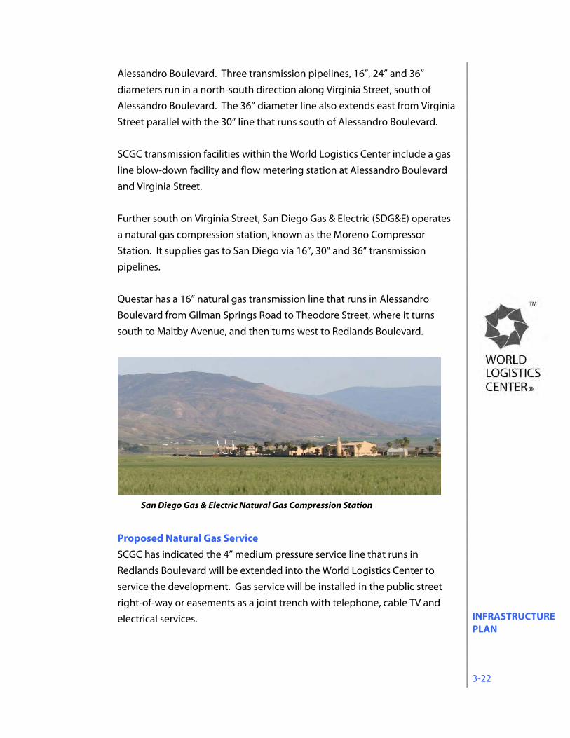
San Diego Gas & Electric Natural Gas Compression Station
INFRASTRUCTURE PLAN 3-23
In connection with the development of the property, relocation of some natural gas transmission lines into public street right-of-way or easements will be necessary. SDG&E’s Moreno Compressor Station will remain in place.
Existing Cable and Telecommunications
Telecommunications Verizon provides telephone services to the World Logistics Center area. Underground telephone facilities are located throughout the project area and run along Alessandro Boulevard and Theodore Street. Four existing telecommunication cabinets are located northeast of the intersection of Alessandro Boulevard and Virginia Street. Overhead telecommunication lines run along Redlands Boulevard. Facilities for telephone service will be provided in every public street.
Cable Television Time Warner Cable currently provides cable television to the World Logistics Center and vicinity. Existing overhead cable television facilities serve the residential area located west of Redlands Boulevard and southwest of Merwin Street and Bay Avenue. Within the World Logistics Center underground cable television facilities run along Alessandro Boulevard from Merwin Street to Theodore Street and overhead on Theodore Street to
Exhibit 3-24 Gas Utility Plan
INFRASTRUCTURE PLAN 3-24
Eucalyptus Avenue. Facilities for cable will be made available to all providers.
Proposed Cable and Telecommunications As development proceeds, cable and telecommunications facilities located west of Redlands Boulevard will be extended to serve the World Logistics Center project. These facilities will be underground and may be provided by a number of service franchises.
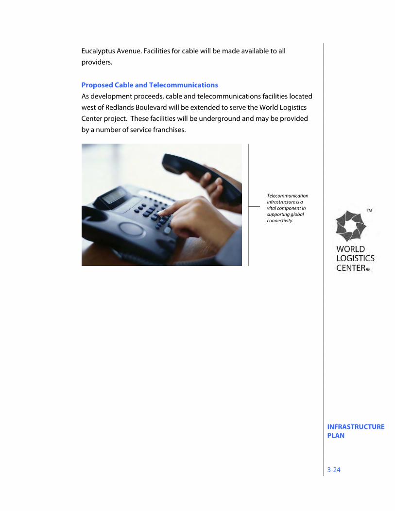
Telecommunication infrastructure is a vital component in supporting global connectivity.
OFF-SITE DESIGN STANDARDS 4-1
4.0 OFF-SITE DESIGN STANDARDS These standards shall apply to those portions of the WLC property that are not within development sites. This includes common areas, open space, public areas, streetscapes, etc.
4.1 Off-site Architecture 4.1.1 Objectives
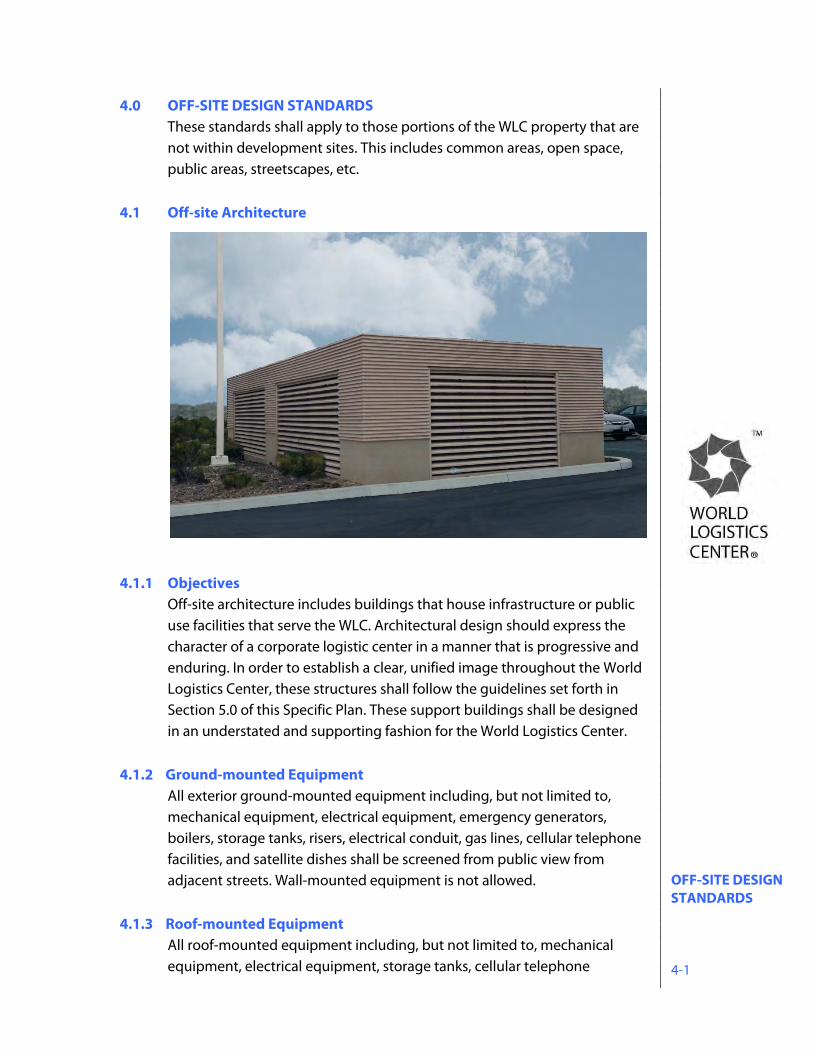
Off-site architecture includes buildings that house infrastructure or public use facilities that serve the WLC. Architectural design should express the character of a corporate logistic center in a manner that is progressive and enduring. In order to establish a clear, unified image throughout the World Logistics Center, these structures shall follow the guidelines set forth in Section 5.0 of this Specific Plan. These support buildings shall be designed in an understated and supporting fashion for the World Logistics Center.
4.1.2 Ground-mounted Equipment
All exterior ground-mounted equipment including, but not limited to, mechanical equipment, electrical equipment, emergency generators, boilers, storage tanks, risers, electrical conduit, gas lines, cellular telephone facilities, and satellite dishes shall be screened from public view from adjacent streets. Wall-mounted equipment is not allowed.
4.1.3 Roof-mounted Equipment
All roof-mounted equipment including, but not limited to, mechanical equipment, electrical equipment, storage tanks, cellular telephone
OFF-SITE DESIGN STANDARDS 4-2
facilities, satellite dishes, skylights, vents, exhaust fans, smoke hatches, and ducts must be below the top of the parapet or equipment screen. Roof access shall be through roof hatches, not exterior ladders. Roof hatches shall be located so that guardrails at parapets are not required.
4.2 Off-site Landscaping 4.2.1 Objectives
Landscaping is an important element contributing to the identity and unity of the World Logistics Center. As such, all landscaping for the project shall: • Promote a pleasant, distinctive corporate environment, • Augment internal cohesion and continuity within the World Logistics
Center, • Enhance the structured design concept of the World Logistics Center, and • Promote water conservation. The landscaping design concept is focused toward: • Providing a clean, contemporary visual appearance, • Coordinating the landscaping treatment along freeway ,
and surface streets to compliment the circulation system, • Coordinating streetscapes within the World Logistics Center to unify its
general appearance, • Ensuring off-site landscaping design continuity among individual
development sites within the World Logistics Center, and • Minimizing long term maintenance . The following guidelines present parameters for general landscape design, water conservation, and streetscapes. On-site landscaping guidelines are addressed in Section 5.4 of this Specific Plan.
4.2.2 Water Conservation Measures The World Logistics Center employs an aggressive approach to water conservation. Every element of the landscape program has been evaluated to determine how to achieve the project’s landscape goals while consuming as little water as possible. From the formulation of the overall landscape concept, through each level of the design process, to the day-to-day maintenance practices of the installed materials, conservation of limited water resources is a constant primary focus. This approach represents a significant departure from conventional development strategies, particularly in a large-scale master-planned

OFF-SITE DESIGN STANDARDS 4-3
logistics campus setting. Most of the project will be designed without mechanical irrigation, relying instead on maximizing the collection and harvesting of runoff to be directed to landscape areas. This program will require the use of carefully selected plant types, complex drainage designs, intricate planting techniques, and specialized maintenance programs. Implementation of these new design concepts will result in a landscape aesthetic that will appear different than traditional landscape treatments. At installation, plant material will be smaller and with greater spacing in order to match available water to the needs of specific plants. As landscaping gets established, coverage may take longer, certain plants will appear dry as they go through dormant periods, and in some cases supplemental watering may be necessary in periods of severe drought. At maturity, the landscaping at the WLC project will provide a strong, clean, simple design element, demonstrating the WLC’s commitment to the creation of a successful logistics campus in a sustainable environment.
The landscape program will incorporate the following design elements and
practices to minimize the use of limited water resources: Project Design:
Design project so that pads, streets and other paved areas drain to landscape areas, medians and parkways,
Maximize water harvesting, retention and treatment techniques throughout the project
Utilize zero-inch curb design to facilitate rainwater runoff from road surfaces
Direct rooftop and parking area runoff to bioswales, basins or landscaped areas
Landscape Design: Develop watershed areas for the project areas in order to manage
water harvesting and distribution Calculate estimated runoff from roofs and paved areas to manage
water harvesting and retention practices Conduct site-specific analyses of seasonal weather patterns, rain
patterns, soils and drainage, grades and slopes, macro and micro climates, solar exposure, prevailing wind conditions, historical evapotranspiration rates and weather station (CIMIS) data
Design to meet peak moisture demand of all plant materials within design zones and avoid flow rates that exceed infiltration rate of soil
Maximize the use of drought tolerant plant species
OFF-SITE DESIGN STANDARDS 4-4
Select plant palettes tolerant of periodic inundation from storm water runoff
Calculate optimum spacing of plants to avoid overcrowding and need for excessive irrigation.
Select container plant sizes are to achieve a high root to canopy ratio; no root bound or oversized plants
Construction: Grade all planting areas to control high intensity rainfall and runoff
episodes. Provide riprap at downspouts; create multiple watersheds to disperse water flow. Use surface mulch and straw wattles.
Grade all planting areas to provide for the retention and infiltration of water to each plant.
Provide soil amendment to plant pits based upon soil laboratory test results and landscape species.
Construct planting pits to be 3-4 times the diameter of the planting container and twice as deep.
Provide a pre-hydration program prior to planting installation to reflect climate and soil conditions.
Cover all planting areas with a combination of organic and inorganic mulches to be used along with pre-emergent herbicide treatment to control weed growth and soil erosion.
Install soil moisture sensors in strategic planting zones. Require certification that the irrigation system was installed and
operates as designed, and conduct a post-installation audit of actual water consumption
Provide for supplemental irrigation on an as-needed basis, such as supply lines and valves, quick-connect couplers or water truck service.
Maintenance: Establish maintenance guidelines to specify actions to replace dead
plants, replenish surface mulch, and remove trash and weeds. Regularly monitor all landscaped areas and make adjustments as
necessary to assure the health of planted materials and progress toward meeting the project’s landscape goals.
Where irrigation is provided: Use planting zones coordinated according to plant type, climatic
exposure, soil condition and slope to facilitate use of zoned irrigation systems Use reclaimed water systems if available and practical,
Use best available irrigation technology to maximize efficient use of water, including moisture sensors, multi-program electronic timers, rain shutoff devices, remote control valves, drip systems, backflow
OFF-SITE DESIGN STANDARDS 4-5
preventers, pressure reducing valves and precipitation-rated sprinkler heads,
Use gate valves to isolate and shut down mainline breaks, Use wind shut-off sensors for the irrigation controllers, Design irrigation systems to prevent discharge onto non-landscaped
areas or adjacent properties, Restrict irrigation cycles to operate at night when wind, evaporation
and activity are at a minimum Coverage:
At installation, plant size, density and spacing shall be as specified in approved landscape plans at 15% coverage.
Based on these design guidelines and average annual rainfall, irrigated and non-irrigated planting groups shall achieve 70% coverage after three years. Until plant material achieves full coverage, a minimum of 3” of mulch will be maintained throughout planted area, and any growth (e.g. weeds) not included in the Specific Plan plant palette shall be removed twice per year (March and September).
All landscape plans shall be reviewed by Eastern Municipal Water District and the City of Moreno Valley.
4.2.3 Streetscapes
Landscaping along public streets is designed to provide a unified appearance along street frontages, to reinforce the street hierarchy, and to establish identities of place, particularly at intersections within the World Logistics Center.
4.2.3.1 General Design Criteria All landscape design and maintenance within the World Logistics Center shall
comply with the Landscape and Water Efficiency Requirements contained in the Municipal Code or these guidelines, whichever imposes a higher design or performance standard.
1. Trees are required along all street frontages according to the criteria for streetscapes given in the following sections.
2. All street trees are to be 24” box within street right of way, unless otherwise noted. Trees in other areas shall be 15 gallon minimum in size but 25% shall be minimum 24” box.
3. Landscaping berms along street frontages may be utilized. Maximum slopes may not exceed 2:1. City maintained areas shall not exceed 3:1.
OFF-SITE DESIGN STANDARDS 4-6
4. Shrubs along street frontages are to be utilized where possible.
(Minimum size at installation is 1 gallon. Minimum size at installation for grasses is 1 gallon.)
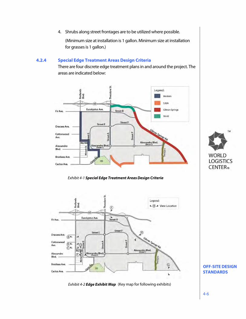
4.2.4 Special Edge Treatment Areas Design Criteria
There are four discrete edge treatment plans in and around the project. The areas are indicated below:
Exhibit 4-1 Special Edge Treatment Areas Design Criteria
(Key map for following exhibits)Exhibit 4-2 Edge Exhibit Map
OFF-SITE DESIGN STANDARDS 4-7
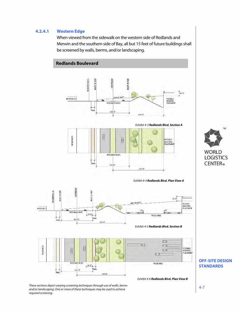
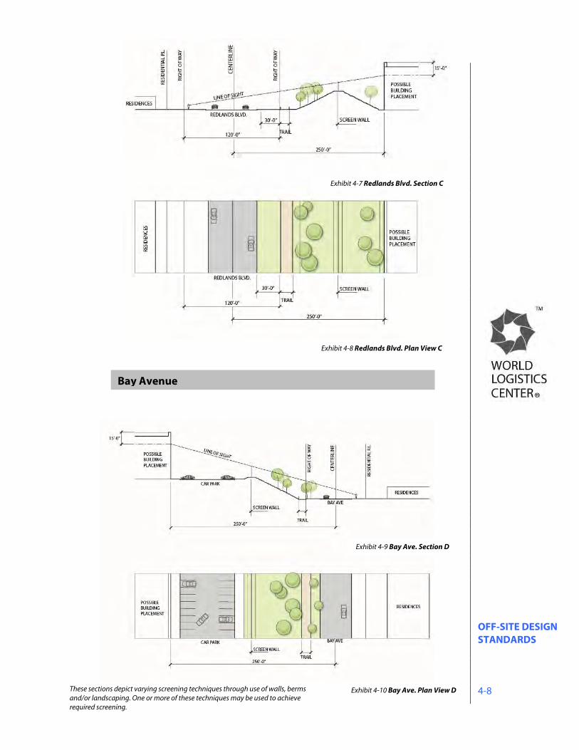
4.2.4.1 Western Edge When viewed from the sidewalk on the western side of Redlands and Merwin and the southern side of Bay, all but 15 feet of future buildings shall be screened by walls, berms, and/or landscaping.
Redlands Boulevard
Exhibit 4-6 Redlands Blvd. Plan View B
These sections depict varying screening techniques through use of walls, berms and/or landscaping. One or more of these techniques may be used to achieve required screening.
Exhibit 4-3 Redlands Blvd. Section A
Exhibit 4-5 Redlands Blvd. Section B
Exhibit 4-4 Redlands Blvd. Plan View A
OFF-SITE DESIGN STANDARDS 4-8
Bay Avenue
Exhibit 4-7 Redlands Blvd. Section C
Exhibit 4-9 Bay Ave. Section D
These sections depict varying screening techniques through use of walls, berms and/or landscaping. One or more of these techniques may be used to achieve required screening.
Exhibit 4-8 Redlands Blvd. Plan View C
Exhibit 4-10 Bay Ave. Plan View D
OFF-SITE DESIGN STANDARDS 4-9
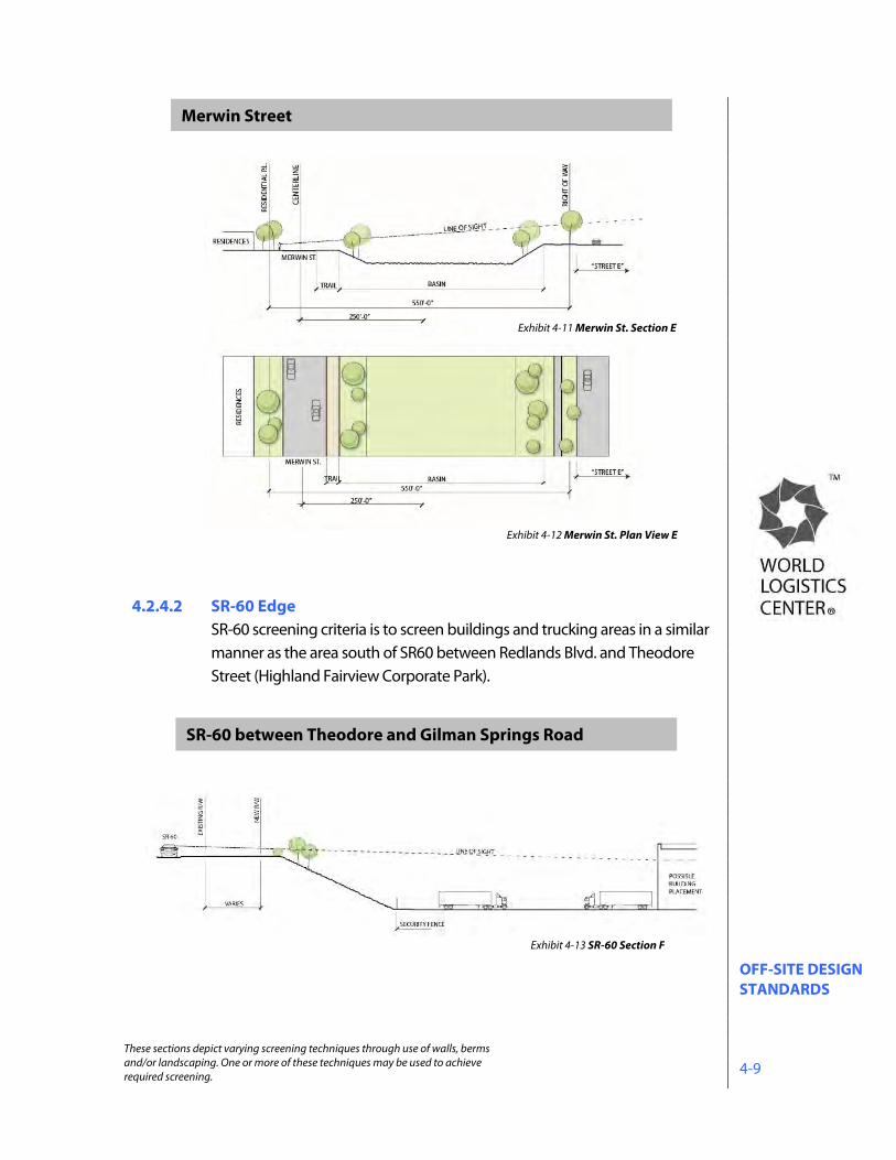
4.2.4.2 SR-60 Edge
SR-60 screening criteria is to screen buildings and trucking areas in a similar manner as the area south of SR60 between Redlands Blvd. and Theodore Street (Highland Fairview Corporate Park).
Merwin Street
SR-60 between Theodore and Gilman Springs Road
Exhibit 4-11 Merwin St. Section E
Exhibit 4-13 SR-60 Section F
These sections depict varying screening techniques through use of walls, berms and/or landscaping. One or more of these techniques may be used to achieve required screening.
Exhibit 4-12 Merwin St. Plan View E
OFF-SITE DESIGN STANDARDS 4-10
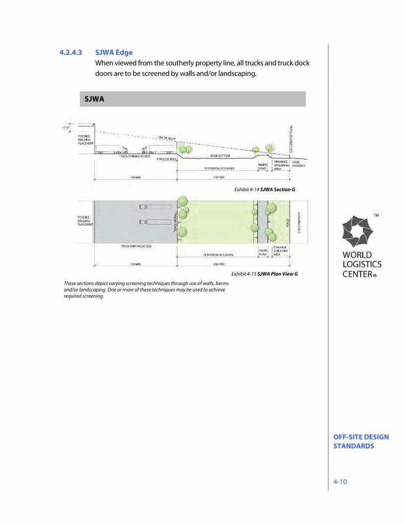
4.2.4.3 SJWA Edge When viewed from the southerly property line, all trucks and truck dock doors are to be screened by walls and/or landscaping.
SJWA
Exhibit 4-14 SJWA Section G
These sections depict varying screening techniques through use of walls, berms and/or landscaping. One or more of these techniques may be used to achieve required screening.
Exhibit 4-15 SJWA Plan View G
OFF-SITE DESIGN STANDARDS 4-11
Exhibit 4-16 SJWA Edge This is a graphic representation of the potential development of property along the project’s southerly property line, adjacent to the San Jacinto Wildlife Area (SJWA). The location, configuration, and size of improvements shown are conceptual and will be refined in connection with detailed engineering plans as the project proceeds. See Section 2.6 of the Specific Plan regarding requirements for the review and approval of a concept plan for the SJWA Edge Treatment Area.
SJWA- View Simulation from SJWA Visitor’s Center
OFF-SITE DESIGN STANDARDS 4-12
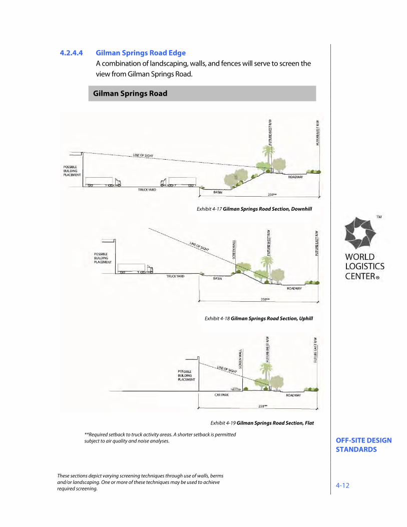
4.2.4.4 Gilman Springs Road Edge A combination of landscaping, walls, and fences will serve to screen the view from Gilman Springs Road.
**Required setback to truck activity areas. A shorter setback is permitted subject to air quality and noise analyses.
Exhibit 4-19 Gilman Springs Road Section, Flat
Exhibit 4-18 Gilman Springs Road Section, Uphill
Exhibit 4-17 Gilman Springs Road Section, Downhill
Gilman Springs Road
These sections depict varying screening techniques through use of walls, berms and/or landscaping. One or more of these techniques may be used to achieve required screening.
OFF-SITE DESIGN STANDARDS 4-13
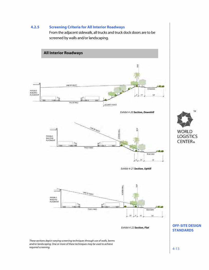
4.2.5 Screening Criteria for All Interior Roadways From the adjacent sidewalk, all trucks and truck dock doors are to be screened by walls and/or landscaping.
All Interior Roadways
Exhibit 4-20 Section, Downhill
Exhibit 4-21 Section, Uphill
Exhibit 4-22 Section, Flat
These sections depict varying screening techniques through use of walls, berms and/or landscaping. One or more of these techniques may be used to achieve required screening.
OFF-SITE DESIGN STANDARDS 4-14
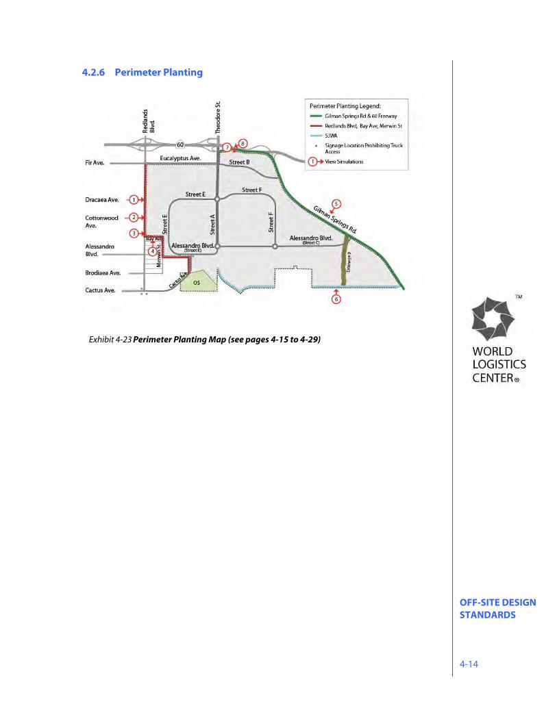
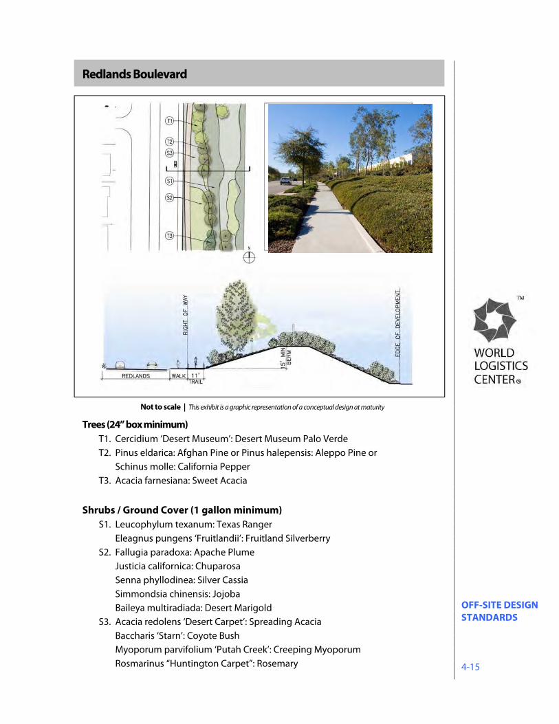
4.2.6 Perimeter Planting
Exhibit 4-23 Perimeter Planting Map (see pages 4-15 to 4-29)
OFF-SITE DESIGN STANDARDS 4-15
Redlands Boulevard
Trees (24” box minimum) T1. Cercidium ‘Desert Museum’: Desert Museum Palo Verde T2. Pinus eldarica: Afghan Pine or Pinus halepensis: Aleppo Pine or
Schinus molle: California Pepper T3. Acacia farnesiana: Sweet Acacia
Shrubs / Ground Cover (1 gallon minimum)
S1. Leucophylum texanum: Texas Ranger Eleagnus pungens ‘Fruitlandii’: Fruitland Silverberry S2. Fallugia paradoxa: Apache Plume
Justicia californica: Chuparosa Senna phyllodinea: Silver Cassia Simmondsia chinensis: Jojoba Baileya multiradiada: Desert Marigold
S3. Acacia redolens ‘Desert Carpet’: Spreading Acacia Baccharis ‘Starn’: Coyote Bush Myoporum parvifolium ‘Putah Creek’: Creeping Myoporum Rosmarinus “Huntington Carpet”: Rosemary
Not to scale | This exhibit is a graphic representation of a conceptual design at maturity
OFF-SITE DESIGN STANDARDS 4-16
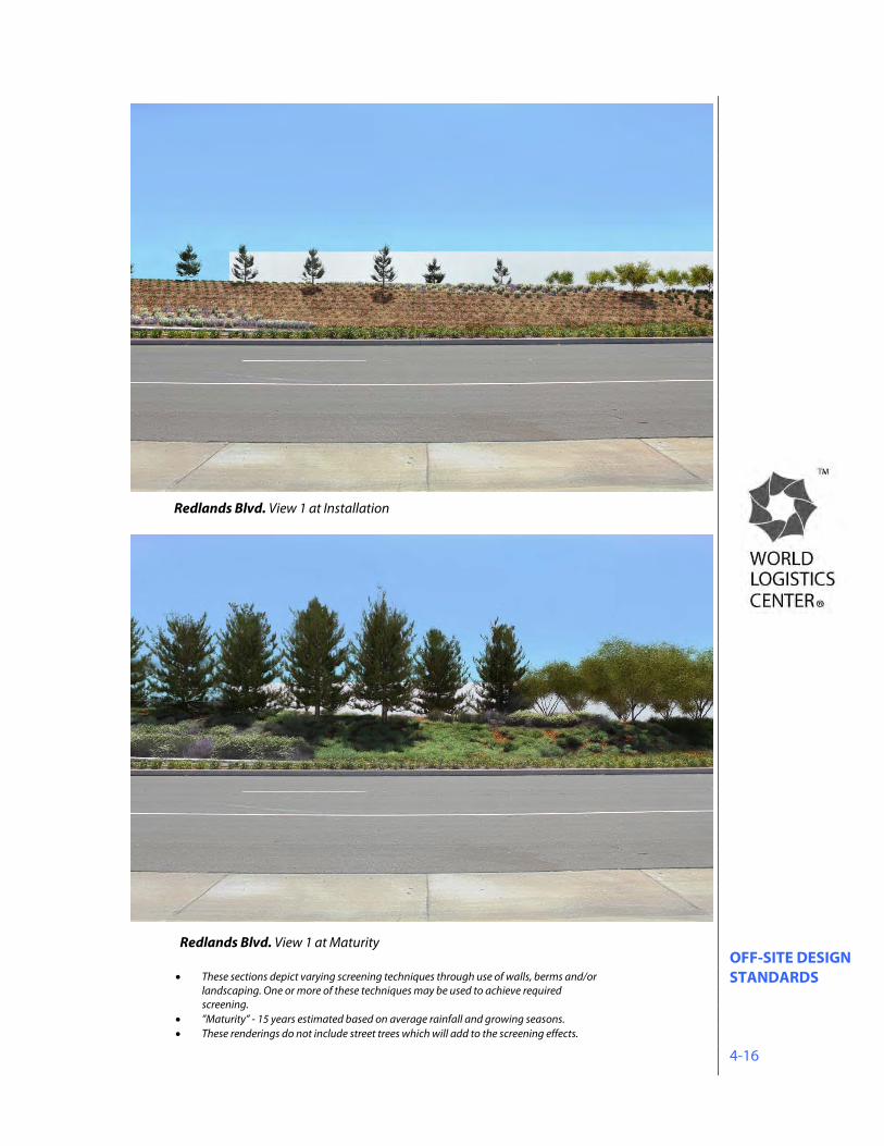
Redlands Blvd. View 1 at Installation
Redlands Blvd. View 1 at Maturity
These sections depict varying screening techniques through use of walls, berms and/or landscaping. One or more of these techniques may be used to achieve required screening.
”Maturity” - 15 years estimated based on average rainfall and growing seasons. These renderings do not include street trees which will add to the screening effects.
OFF-SITE DESIGN STANDARDS 4-17
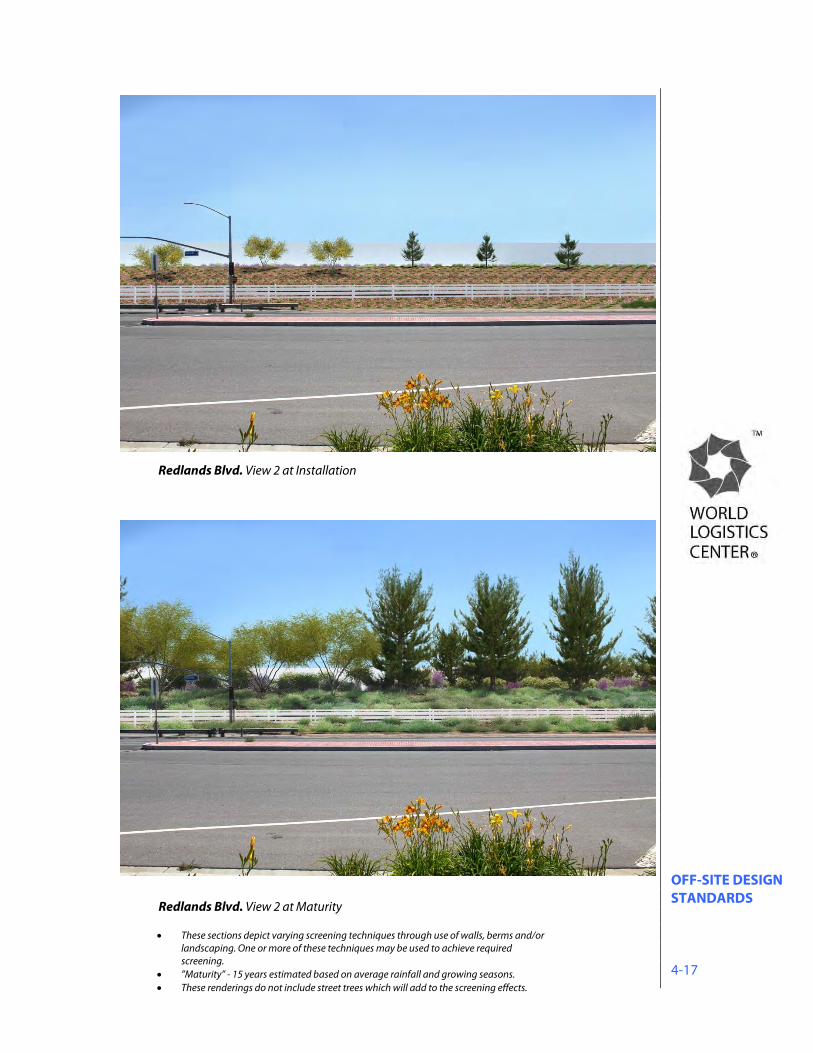
Redlands Blvd. View 2 at Installation
Redlands Blvd. View 2 at Maturity
These sections depict varying screening techniques through use of walls, berms and/or landscaping. One or more of these techniques may be used to achieve required screening.
”Maturity” - 15 years estimated based on average rainfall and growing seasons. These renderings do not include street trees which will add to the screening effects.
OFF-SITE DESIGN STANDARDS 4-18
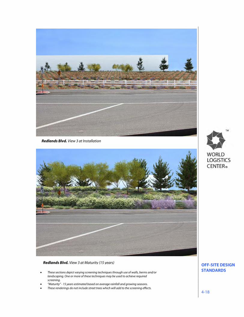
Redlands Blvd. View 3 at Maturity (15 years)
Redlands Blvd. View 3 at Installation
These sections depict varying screening techniques through use of walls, berms and/or landscaping. One or more of these techniques may be used to achieve required screening.
”Maturity” - 15 years estimated based on average rainfall and growing seasons. These renderings do not include street trees which will add to the screening effects.
OFF-SITE DESIGN STANDARDS 4-19
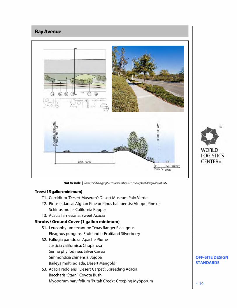
Bay Avenue
Trees (15 gallon minimum)
T1. Cercidium ‘Desert Museum’: Desert Museum Palo Verde T2. Pinus eldarica: Afghan Pine or Pinus halepensis: Aleppo Pine or
Schinus molle: California Pepper T3. Acacia farnesiana: Sweet Acacia
Shrubs / Ground Cover (1 gallon minimum) S1. Leucophylum texanum: Texas Ranger Elaeagnus
Eleagnus pungens ‘Fruitlandii’: Fruitland Silverberry S2. Fallugia paradoxa: Apache Plume
Justicia californica: Chuparosa Senna phyllodinea: Silver Cassia Simmondsia chinensis: Jojoba Baileya multiradiada: Desert Marigold
S3. Acacia redolens ‘ Desert Carpet’: Spreading Acacia Baccharis ‘Starn’: Coyote Bush
Myoporum parvifolium ‘Putah Creek’: Creeping Myoporum
Not to scale | This exhibit is a graphic representation of a conceptual design at maturity
OFF-SITE DESIGN STANDARDS 4-20
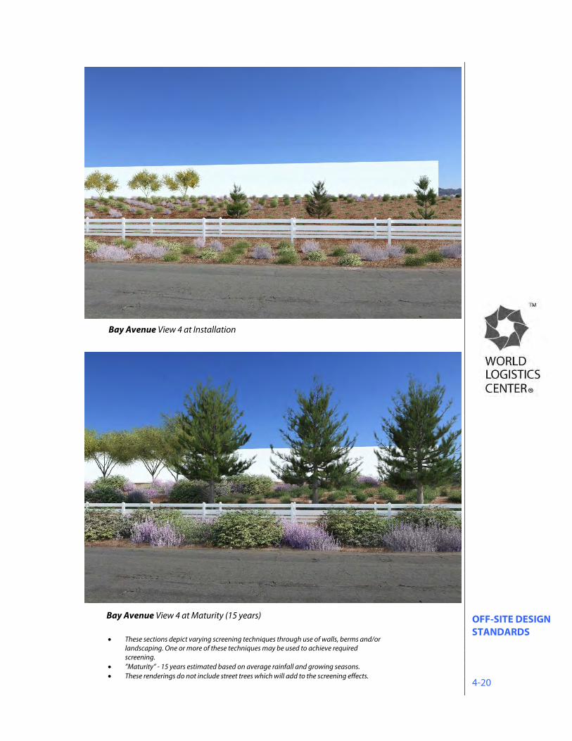
Bay Avenue View 4 at Maturity (15 years)
Bay Avenue View 4 at Installation
These sections depict varying screening techniques through use of walls, berms and/or landscaping. One or more of these techniques may be used to achieve required screening.
”Maturity” - 15 years estimated based on average rainfall and growing seasons. These renderings do not include street trees which will add to the screening effects.
OFF-SITE DESIGN STANDARDS 4-21
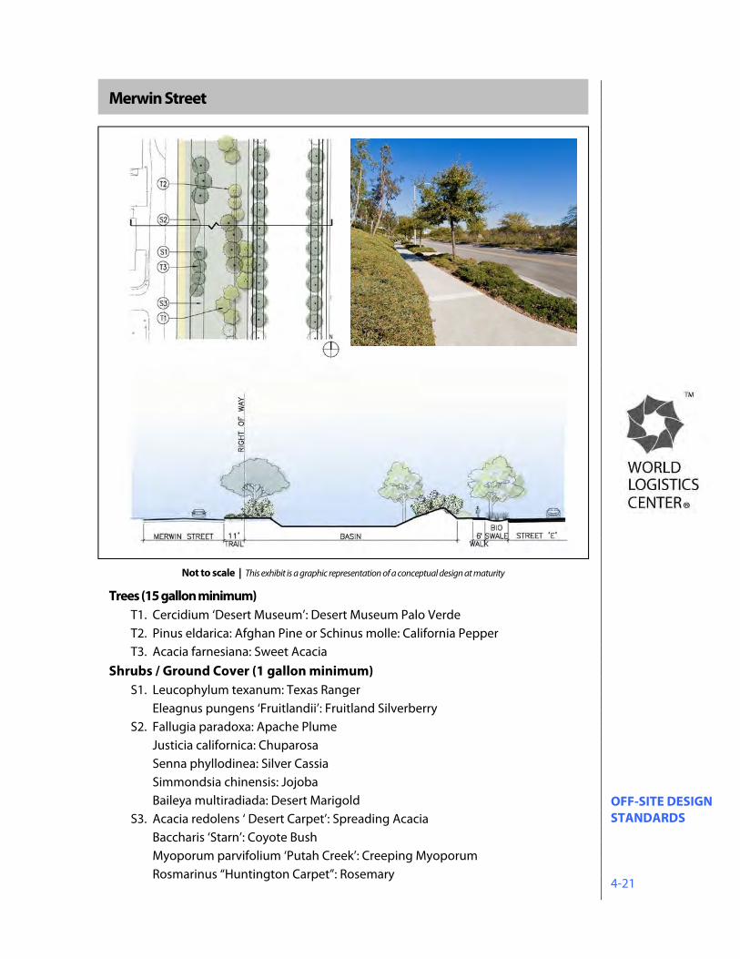
Merwin Street
Trees (15 gallon minimum) T1. Cercidium ‘Desert Museum’: Desert Museum Palo Verde T2. Pinus eldarica: Afghan Pine or Schinus molle: California Pepper T3. Acacia farnesiana: Sweet Acacia
Shrubs / Ground Cover (1 gallon minimum) S1. Leucophylum texanum: Texas Ranger
Eleagnus pungens ‘Fruitlandii’: Fruitland Silverberry S2. Fallugia paradoxa: Apache Plume
Justicia californica: Chuparosa Senna phyllodinea: Silver Cassia Simmondsia chinensis: Jojoba Baileya multiradiada: Desert Marigold
S3. Acacia redolens ‘ Desert Carpet’: Spreading Acacia Baccharis ‘Starn’: Coyote Bush
Myoporum parvifolium ‘Putah Creek’: Creeping Myoporum Rosmarinus “Huntington Carpet”: Rosemary
Not to scale | This exhibit is a graphic representation of a conceptual design at maturity
OFF-SITE DESIGN STANDARDS 4-22
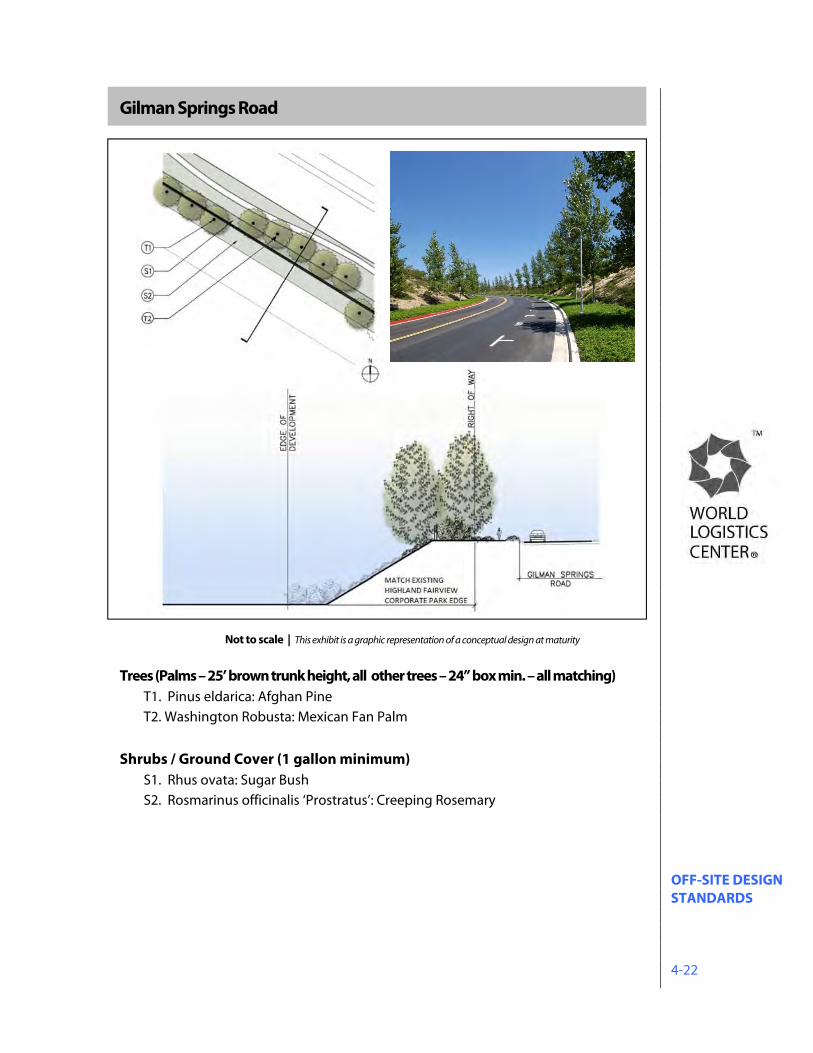
Gilman Springs Road
Trees (Palms – 25’ brown trunk height, all other trees – 24” box min. – all matching)
T1. Pinus eldarica: Afghan Pine T2. Washington Robusta: Mexican Fan Palm
Shrubs / Ground Cover (1 gallon minimum) S1. Rhus ovata: Sugar Bush S2. Rosmarinus officinalis ‘Prostratus’: Creeping Rosemary
Not to scale | This exhibit is a graphic representation of a conceptual design at maturity
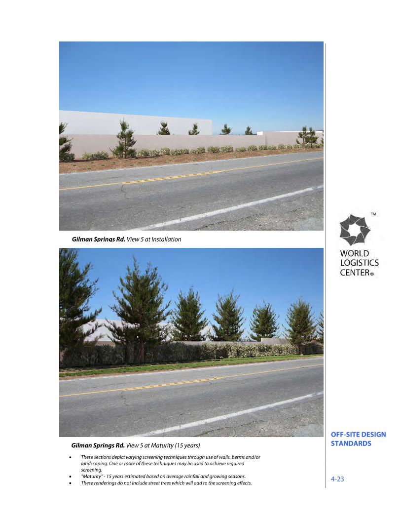
OFF-SITE DESIGN STANDARDS 4-23
Gilman Springs Rd. View 5 at Maturity (15 years)
Gilman Springs Rd. View 5 at Installation
These sections depict varying screening techniques through use of walls, berms and/or landscaping. One or more of these techniques may be used to achieve required screening.
”Maturity” - 15 years estimated based on average rainfall and growing seasons. These renderings do not include street trees which will add to the screening effects.
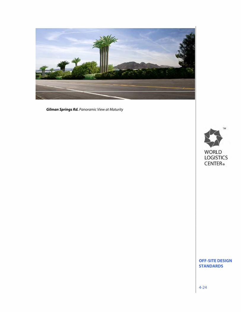
OFF-SITE DESIGN STANDARDS 4-24
Gilman Springs Rd. Panoramic View at Maturity
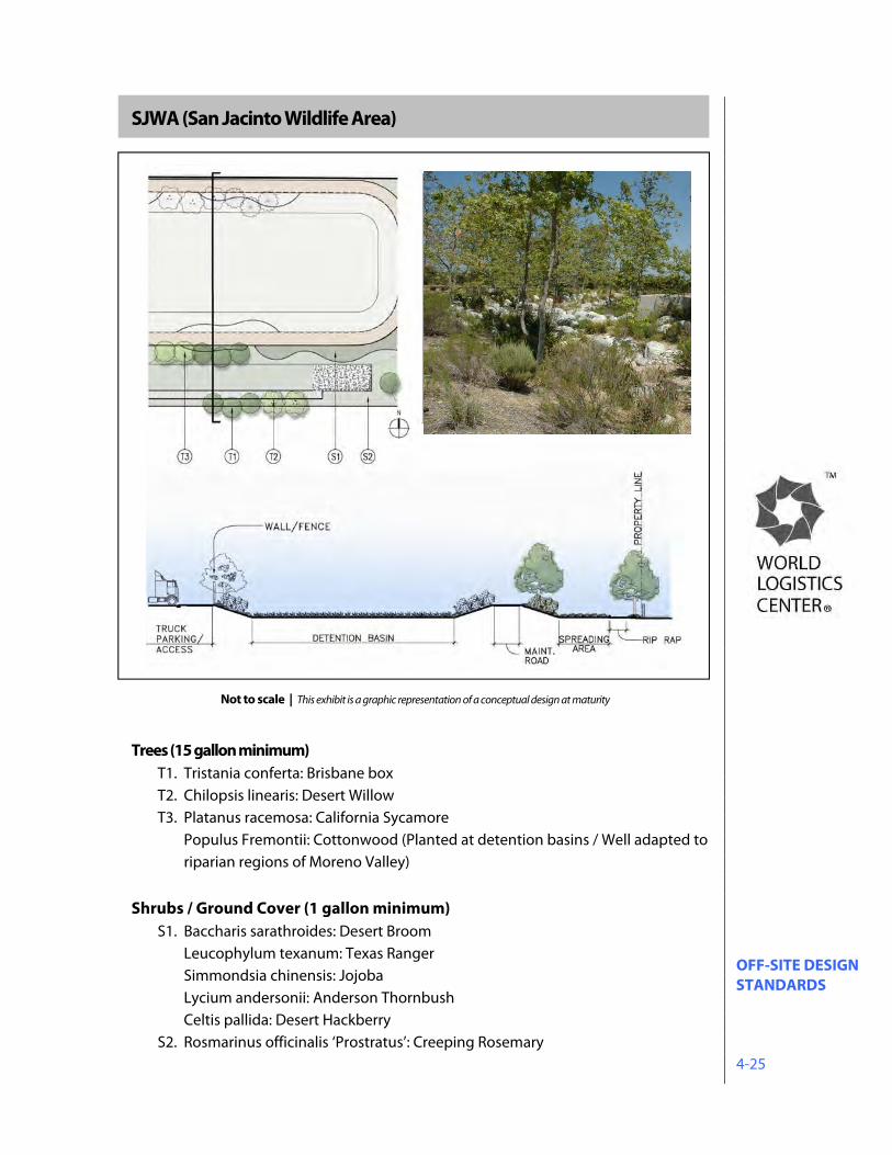
OFF-SITE DESIGN STANDARDS 4-25
SJWA (San Jacinto Wildlife Area)
Trees (15 gallon minimum)
T1. Tristania conferta: Brisbane box T2. Chilopsis linearis: Desert Willow T3. Platanus racemosa: California Sycamore
Populus Fremontii: Cottonwood (Planted at detention basins / Well adapted to riparian regions of Moreno Valley)
Shrubs / Ground Cover (1 gallon minimum)
S1. Baccharis sarathroides: Desert Broom Leucophylum texanum: Texas Ranger Simmondsia chinensis: Jojoba Lycium andersonii: Anderson Thornbush
Celtis pallida: Desert Hackberry S2. Rosmarinus officinalis ‘Prostratus’: Creeping Rosemary
Not to scale | This exhibit is a graphic representation of a conceptual design at maturity
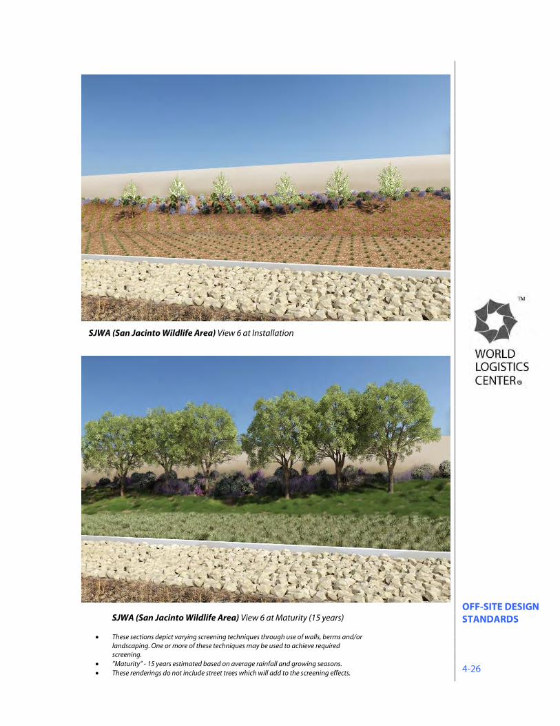
OFF-SITE DESIGN STANDARDS 4-26
SJWA (San Jacinto Wildlife Area) View 6 at Maturity (15 years)
SJWA (San Jacinto Wildlife Area) View 6 at Installation
These sections depict varying screening techniques through use of walls, berms and/or landscaping. One or more of these techniques may be used to achieve required screening.
”Maturity” - 15 years estimated based on average rainfall and growing seasons. These renderings do not include street trees which will add to the screening effects.
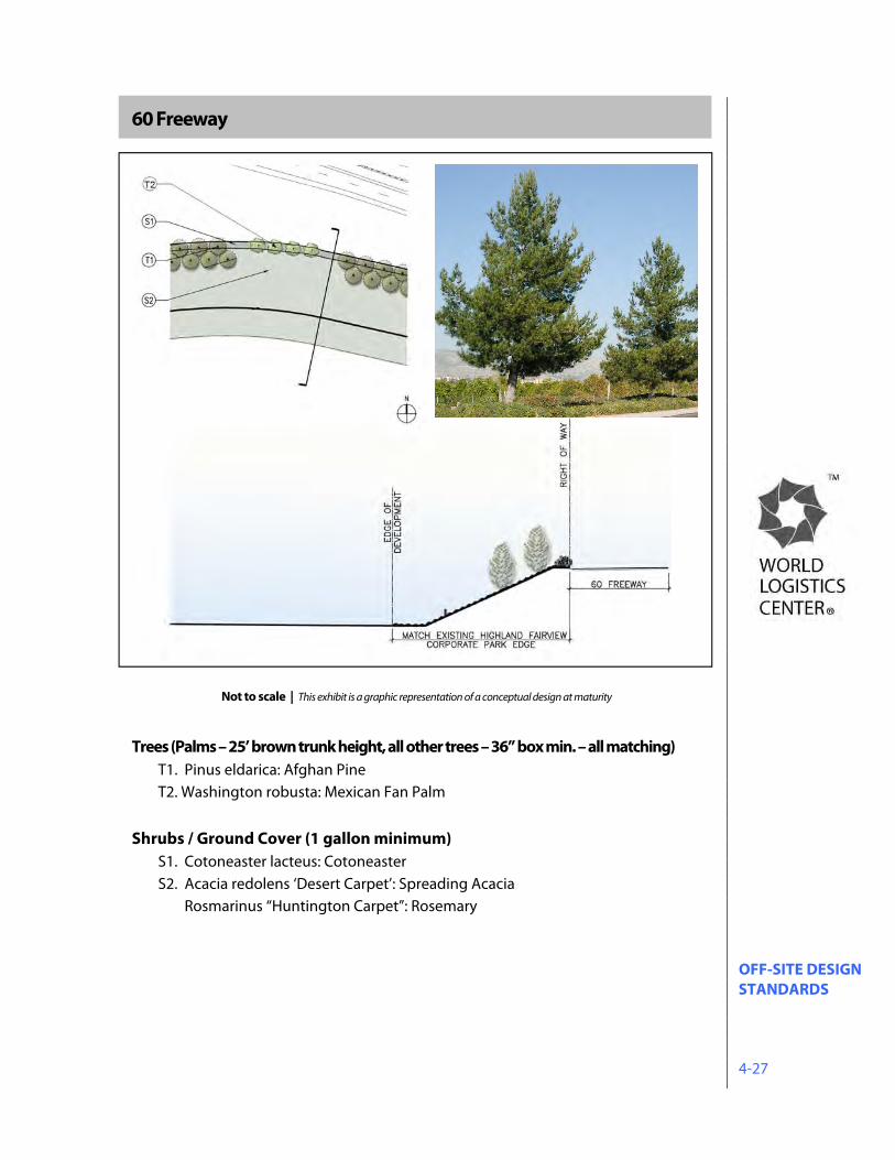
OFF-SITE DESIGN STANDARDS 4-27
60 Freeway
Trees (Palms – 25’ brown trunk height, all other trees – 36” box min. – all matching) T1. Pinus eldarica: Afghan Pine T2. Washington robusta: Mexican Fan Palm
Shrubs / Ground Cover (1 gallon minimum) S1. Cotoneaster lacteus: Cotoneaster S2. Acacia redolens ‘Desert Carpet’: Spreading Acacia Rosmarinus “Huntington Carpet”: Rosemary
Not to scale | This exhibit is a graphic representation of a conceptual design at maturity
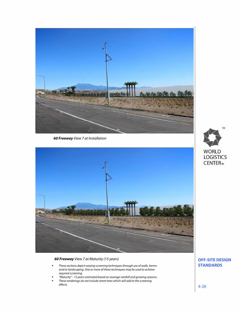
OFF-SITE DESIGN STANDARDS 4-28
60 Freeway View 7 at Maturity (15 years)
60 Freeway View 7 at Installation
These sections depict varying screening techniques through use of walls, berms and/or landscaping. One or more of these techniques may be used to achieve required screening.
”Maturity” - 15 years estimated based on average rainfall and growing seasons. These renderings do not include street trees which will add to the screening
effects.
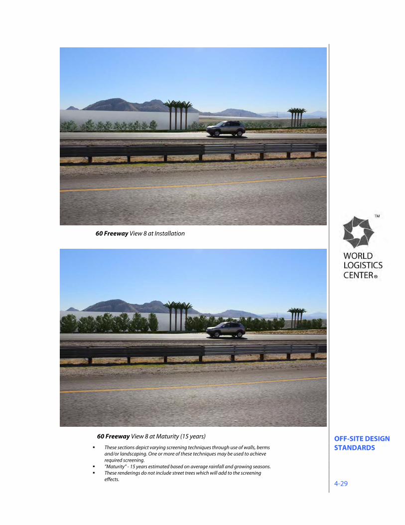
OFF-SITE DESIGN STANDARDS 4-29
60 Freeway View 8 at Maturity (15 years)
60 Freeway View 8 at Installation
These sections depict varying screening techniques through use of walls, berms and/or landscaping. One or more of these techniques may be used to achieve required screening.
”Maturity” - 15 years estimated based on average rainfall and growing seasons. These renderings do not include street trees which will add to the screening
effects.
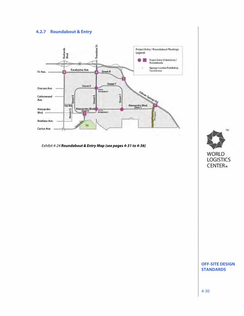
OFF-SITE DESIGN STANDARDS 4-30
4.2.7 Roundabout & Entry
Exhibit 4-24 Roundabout & Entry Map (see pages 4-31 to 4-36)
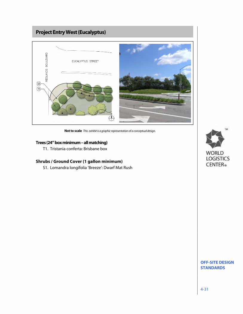
OFF-SITE DESIGN STANDARDS 4-31
Project Entry West (Eucalyptus)
\
Trees (24” box minimum – all matching) T1. Tristania conferta: Brisbane box
Shrubs / Ground Cover (1 gallon minimum)
S1. Lomandra longifolia ‘Breeze’: Dwarf Mat Rush
Not to scale This exhibit is a graphic representation of a conceptual design.
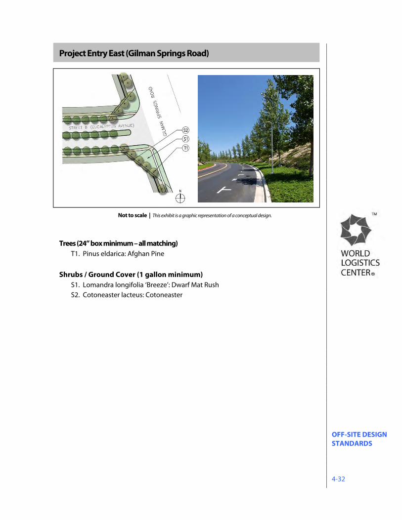
OFF-SITE DESIGN STANDARDS 4-32
Project Entry East (Gilman Springs Road)
Trees (24” box minimum – all matching) T1. Pinus eldarica: Afghan Pine
Shrubs / Ground Cover (1 gallon minimum)
S1. Lomandra longifolia ‘Breeze’: Dwarf Mat Rush S2. Cotoneaster lacteus: Cotoneaster
Not to scale | This exhibit is a graphic representation of a conceptual design.
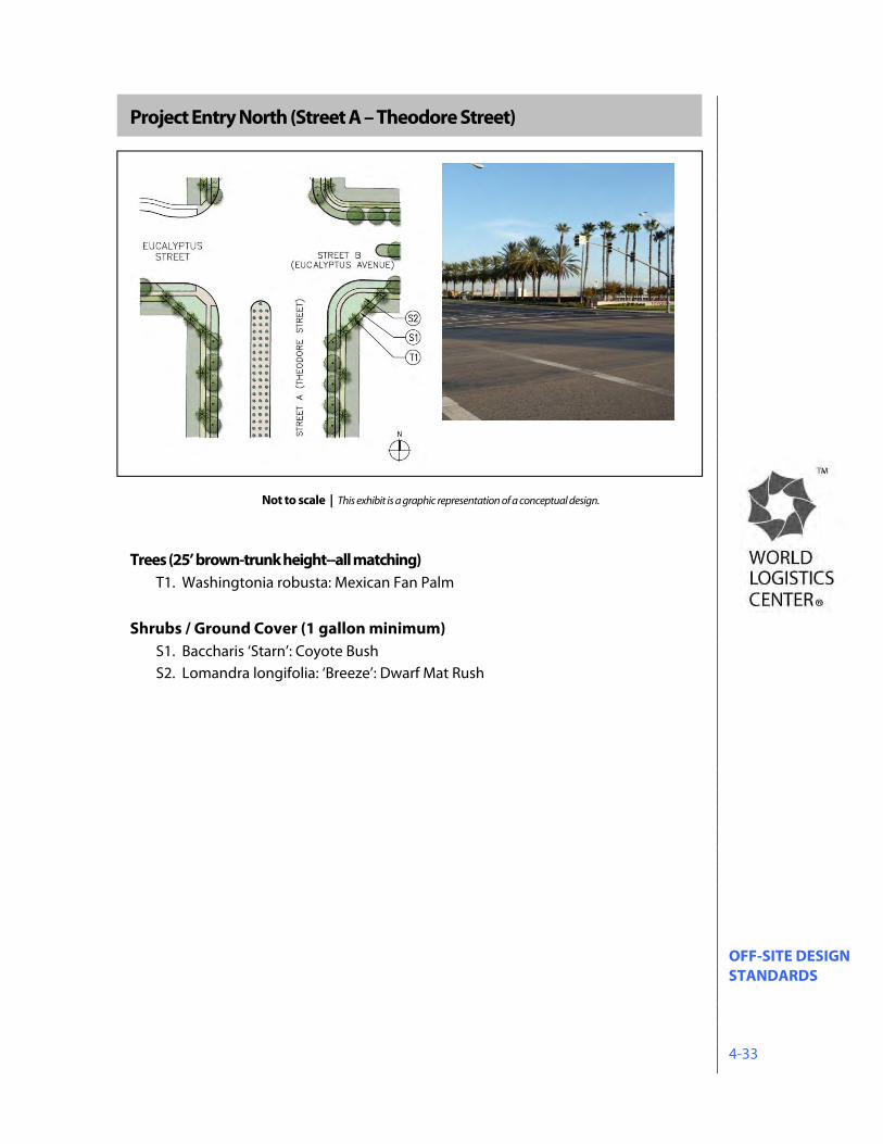
OFF-SITE DESIGN STANDARDS 4-33
Project Entry North (Street A – Theodore Street)
Trees (25’ brown-trunk height--all matching)
T1. Washingtonia robusta: Mexican Fan Palm Shrubs / Ground Cover (1 gallon minimum)
S1. Baccharis ‘Starn’: Coyote Bush S2. Lomandra longifolia: ‘Breeze’: Dwarf Mat Rush
Not to scale | This exhibit is a graphic representation of a conceptual design.
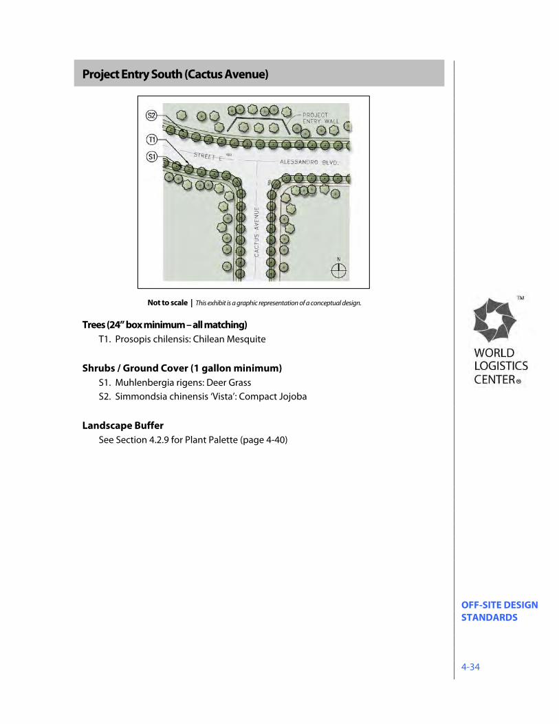
OFF-SITE DESIGN STANDARDS 4-34
Project Entry South (Cactus Avenue)
Trees (24” box minimum – all matching)
T1. Prosopis chilensis: Chilean Mesquite Shrubs / Ground Cover (1 gallon minimum)
S1. Muhlenbergia rigens: Deer Grass S2. Simmondsia chinensis ‘Vista’: Compact Jojoba
Landscape Buffer See Section 4.2.9 for Plant Palette (page 4-40)
Not to scale | This exhibit is a graphic representation of a conceptual design.
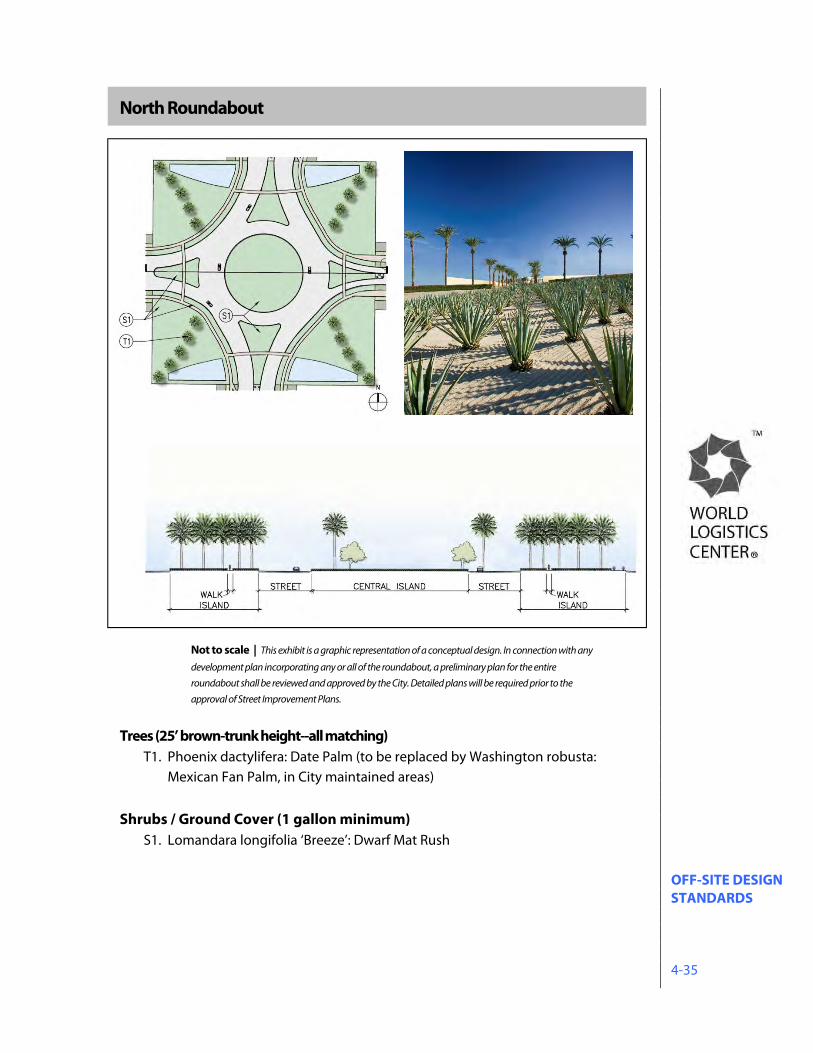
OFF-SITE DESIGN STANDARDS 4-35
North Roundabout
Trees (25’ brown-trunk height--all matching) T1. Phoenix dactylifera: Date Palm (to be replaced by Washington robusta:
Mexican Fan Palm, in City maintained areas) Shrubs / Ground Cover (1 gallon minimum)
S1. Lomandara longifolia ‘Breeze’: Dwarf Mat Rush
Not to scale | This exhibit is a graphic representation of a conceptual design. In connection with any
development plan incorporating any or all of the roundabout, a preliminary plan for the entire
roundabout shall be reviewed and approved by the City. Detailed plans will be required prior to the
approval of Street Improvement Plans.
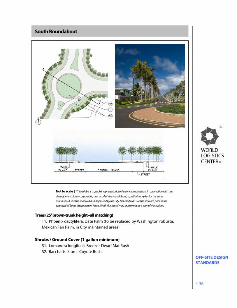
OFF-SITE DESIGN STANDARDS 4-36
South Roundabout
Trees (25’ brown-trunk height--all matching) T1. Phoenix dactylifera: Date Palm (to be replaced by Washington robusta: Mexican Fan Palm, in City maintained areas)
Shrubs / Ground Cover (1 gallon minimum)
S1. Lomandra longifolia ‘Breeze’: Dwarf Mat Rush S2. Baccharis ‘Starn’: Coyote Bush
Not to scale | This exhibit is a graphic representation of a conceptual design. In connection with any
development plan incorporating any or all of the roundabout, a preliminary plan for the entire
roundabout shall be reviewed and approved by the City. Detailed plans will be required prior to the
approval of Street Improvement Plans. Walls illustrated may or may not be a part of these plans.
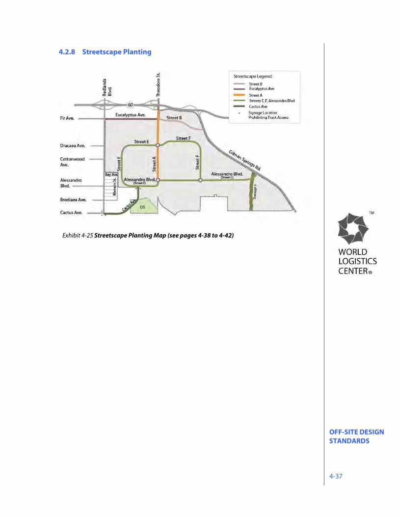
OFF-SITE DESIGN STANDARDS 4-37
4.2.8 Streetscape Planting
Exhibit 4-25 Streetscape Planting Map (see pages 4-38 to 4-42)
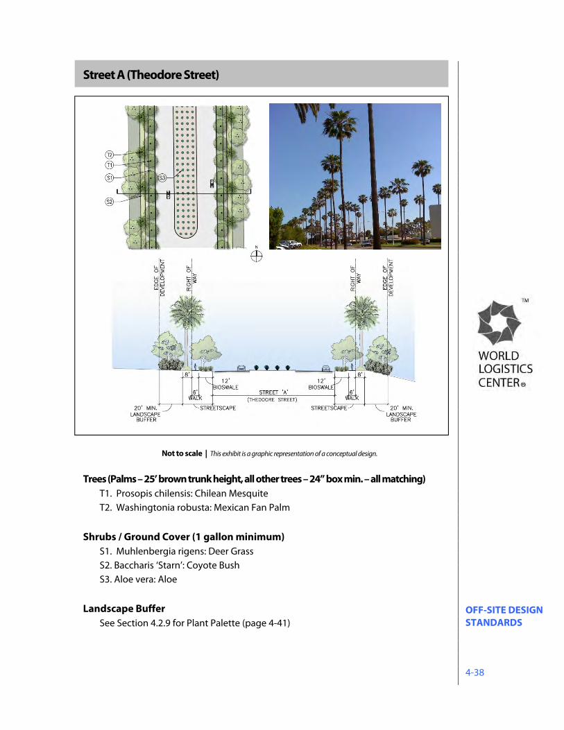
OFF-SITE DESIGN STANDARDS 4-38
Street A (Theodore Street)
Trees (Palms – 25’ brown trunk height, all other trees – 24” box min. – all matching) T1. Prosopis chilensis: Chilean Mesquite T2. Washingtonia robusta: Mexican Fan Palm
Shrubs / Ground Cover (1 gallon minimum)
S1. Muhlenbergia rigens: Deer Grass S2. Baccharis ‘Starn’: Coyote Bush S3. Aloe vera: Aloe
Landscape Buffer See Section 4.2.9 for Plant Palette (page 4-41)
Not to scale | This exhibit is a graphic representation of a conceptual design.
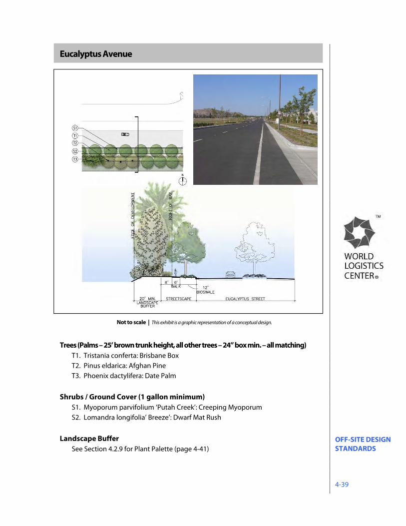
OFF-SITE DESIGN STANDARDS 4-39
Eucalyptus Avenue
Trees (Palms – 25’ brown trunk height, all other trees – 24” box min. – all matching) T1. Tristania conferta: Brisbane Box T2. Pinus eldarica: Afghan Pine T3. Phoenix dactylifera: Date Palm
Shrubs / Ground Cover (1 gallon minimum)
S1. Myoporum parvifolium ‘Putah Creek’: Creeping Myoporum S2. Lomandra longifolia’ Breeze’: Dwarf Mat Rush
Landscape Buffer See Section 4.2.9 for Plant Palette (page 4-41)
Not to scale | This exhibit is a graphic representation of a conceptual design.
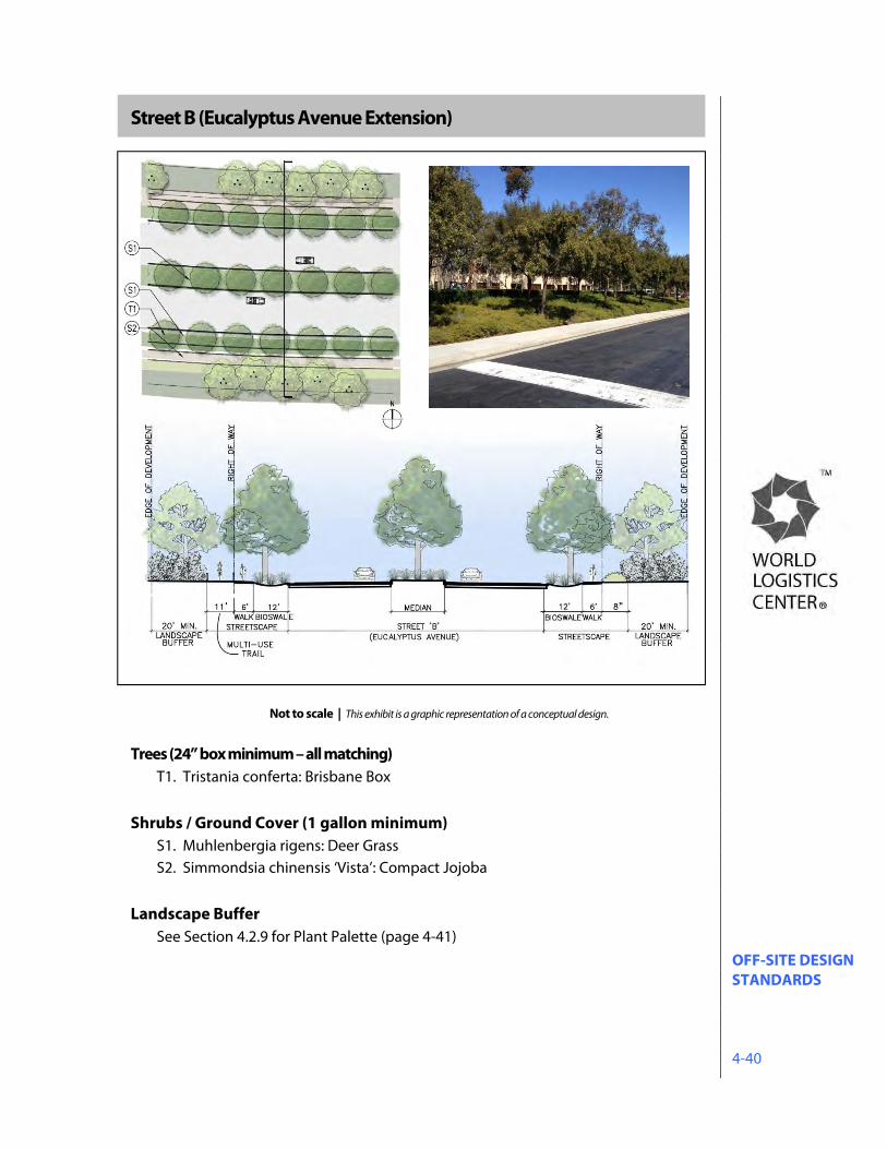
OFF-SITE DESIGN STANDARDS 4-40
Street B (Eucalyptus Avenue Extension)
Trees (24” box minimum – all matching) T1. Tristania conferta: Brisbane Box
Shrubs / Ground Cover (1 gallon minimum)
S1. Muhlenbergia rigens: Deer Grass S2. Simmondsia chinensis ‘Vista’: Compact Jojoba
Landscape Buffer See Section 4.2.9 for Plant Palette (page 4-41)
Not to scale | This exhibit is a graphic representation of a conceptual design.
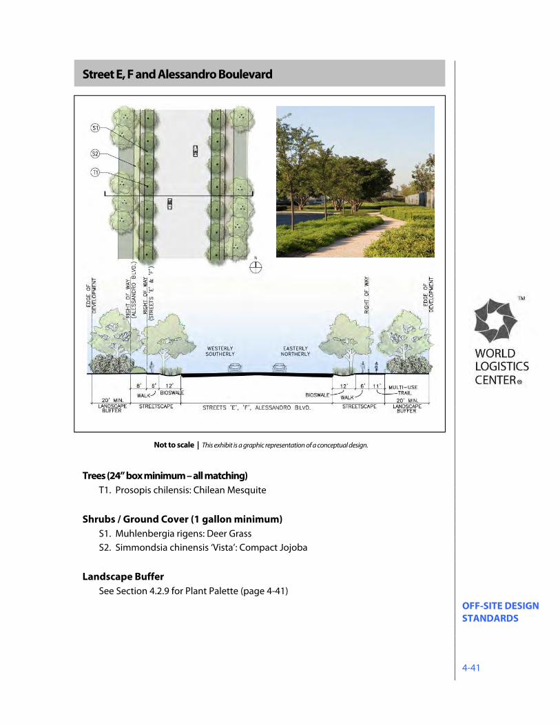
OFF-SITE DESIGN STANDARDS 4-41
Street E, F and Alessandro Boulevard
\
Trees (24” box minimum – all matching) T1. Prosopis chilensis: Chilean Mesquite
Shrubs / Ground Cover (1 gallon minimum)
S1. Muhlenbergia rigens: Deer Grass S2. Simmondsia chinensis ‘Vista’: Compact Jojoba
Landscape Buffer See Section 4.2.9 for Plant Palette (page 4-41)
Not to scale | This exhibit is a graphic representation of a conceptual design.

OFF-SITE DESIGN STANDARDS 4-42
Cactus Avenue
\
Trees (24” box minimum – all matching) T1. Prosopis chilensis: Chilean Mesquite
Shrubs / Ground Cover (1 gallon minimum)
S1. Muhlenbergia rigens: Deer Grass S2. Simmondsia chinensis ‘Vista’: Compact Jojoba
Landscape Buffer See Section 4.2.9 for Plant Palette (page 4-41)
Not to scale | This exhibit is a graphic representation of a conceptual design.
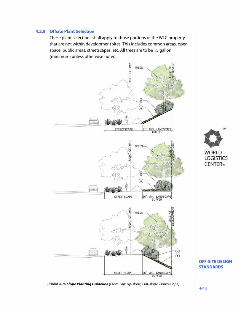
OFF-SITE DESIGN STANDARDS 4-43
4.2.9 Offsite Plant Selection These plant selections shall apply to those portions of the WLC property that are not within development sites. This includes common areas, open space, public areas, streetscapes, etc. All trees are to be 15 gallon (minimum) unless otherwise noted.
Exhibit 4-26 Slope Planting Guideline (From Top: Up-slope, Flat-slope, Down-slope)
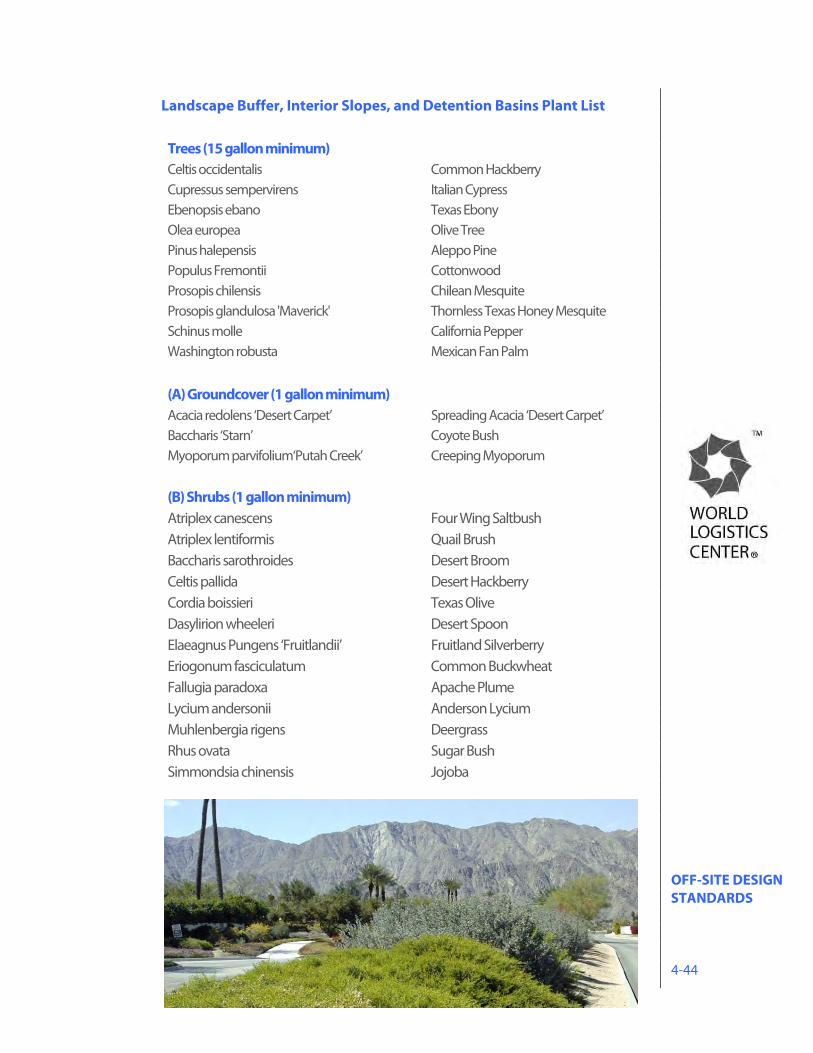
OFF-SITE DESIGN STANDARDS 4-44
Landscape Buffer, Interior Slopes, and Detention Basins Plant List Trees (15 gallon minimum) Celtis occidentalis Common Hackberry Cupressus sempervirens Italian Cypress Ebenopsis ebano Texas Ebony Olea europea Olive Tree Pinus halepensis Aleppo Pine Populus Fremontii Cottonwood Prosopis chilensis Chilean Mesquite Prosopis glandulosa 'Maverick' Thornless Texas Honey Mesquite Schinus molle California Pepper Washington robusta Mexican Fan Palm (A) Groundcover (1 gallon minimum) Acacia redolens ‘Desert Carpet’ Spreading Acacia ‘Desert Carpet’ Baccharis ‘Starn’ Coyote Bush Myoporum parvifolium‘Putah Creek’ Creeping Myoporum (B) Shrubs (1 gallon minimum) Atriplex canescens Four Wing Saltbush Atriplex lentiformis Quail Brush Baccharis sarothroides Desert Broom Celtis pallida Desert Hackberry Cordia boissieri Texas Olive Dasylirion wheeleri Desert Spoon Elaeagnus Pungens ‘Fruitlandii’ Fruitland Silverberry Eriogonum fasciculatum Common Buckwheat Fallugia paradoxa Apache Plume Lycium andersonii Anderson Lycium Muhlenbergia rigens Deergrass Rhus ovata Sugar Bush Simmondsia chinensis Jojoba
OFF-SITE DESIGN STANDARDS 4-45
4.2.10 Off-site Maintenance Public streets (curb-to-curb), sidewalks, and trails will be maintained by the City. If the City is responsible for maintaining medians and/or curb separated parkways, funding of the maintenance will require a special financing district. These details to be established with each site specific Plot Plan application or Tentative Map. Parkways, slopes, drainage facilities, and common areas will be maintained by a property owners’ association.
4.3 Off-site Lighting 4.3.1 Objectives
Exterior lighting is to be provided to enhance the safety and security of motorists, pedestrians and cyclists. Lighting is intended to create a night time character that reinforces the image of the World Logistics Center as a quality business location. Lighting is an important element contributing to the identity and unity of the World Logistics Center. To reinforce identity and unity, all exterior lighting is to be consistent in height, spacing, color and type of fixture throughout the building site and compatible throughout the World Logistics Center. All lighting in the vicinity of the San Jacinto Wildlife Area shall be designed to confine all direct light rays to the project site and avoid the visibility of direct light rays from the wildlife area. Street lighting on public streets shall meet the requirements of the City Standard Plans.
4.4 Off-site Utilities 4.4.1 Telephone, CATV and Similar Service Wires and Cables
All telephone, CATV and similar service wires and cables shall be installed underground.
4.4.2 Electrical Transmission Lines
Electrical transmission lines less than 115kV shall be installed underground.
ON-SITE DESIGN STANDARDS 5-1
5.0 ON-SITE DESIGN STANDARDS 5.1 On-site Design Standards And Guidelines
In order to manage the orderly and consistent development of the World Logistics Center, the following design standards and guidelines will be applied to all development in the Specific Plan area. These Design Standards and Guidelines serve to create an eco-friendly, high-quality development and establish a distinctive character for the World Logistics Center project. In reviewing development proposals, these guidelines will be the primary tool used to evaluate proposed site design, architecture, landscaping, and other project features such as lighting and site amenities.
5.1.1 General Purpose
On-site design standards and guidelines are set forth to guide the design, construction, review and approval of all buildings within the World Logistics Center. The goal is to attain the best possible design for each site within the World Logistics Center.
5.1.2 Uses Shall Be Developed In Accordance with the Specific Plan
All properties within the World Logistics Center shall be developed in conformance with this Specific Plan.
5.1.3 Uses Shall Be Developed In Accordance With City of Moreno Valley
Municipal Codes All development will be consistent with the Specific Plan objectives and design guidelines. Details of specific development projects will be determined by subdivisions and site development plans. In the event of a
ON-SITE DESIGN STANDARDS 5-2
conflict between the Specific Plan and the City of Moreno Valley Municipal Code, the Specific Plan will prevail. If the Specific Plan is silent on a particular subject, the Municipal Code will apply.
5.1.4 Subdivision Map Act
Lots created within the World Logistics Center Specific Plan area shall comply with the Subdivision Map Act and be in conformance with the Specific Plan.
5.1.5 Water Quality Management Plan
All development within the World Logistics Center shall be subject to applicable laws of the State of California regarding water quality.
5.1.6 Trash and Recyclable Materials
All development within the World Logistics Center shall provide enclosures (or compactors) for collection of trash and recyclable materials subject to water quality standards and best management practices.
5.1.7 Waste Hauling
Construction and other waste disposal shall be hauled to a city-approved facility.
5.1.8 Water Quality Site Design 5.1.8.1 General Standards
Refer to the National Pollution Discharge Elimination System (NPDES) Permit Board Order R8-2010-0033 for complete and current information on water quality management standards. Current requirements can be obtained by visiting the State Water Resource Control Board website at www.swrcb.ca.gov.
5.1.8.2 Water Quality Management Plan
Most developments are required to implement a Water Quality Management Plan (WQMP) in accordance with the NPDES Permit Board Order R8-2010-0033. The WQMP for the Santa Ana Region of Riverside County was approved by the Santa Ana Region Water Quality Control Board on October 22, 2012. Projects identified as a ‘Priority Development project’ are required to prepare a Project-Specific WQMP. The MS4 Permit mandates a Low Impact Development (LID) approach to stormwater treatment and management of runoff discharges. The project site should be designed to minimize imperviousness, detain
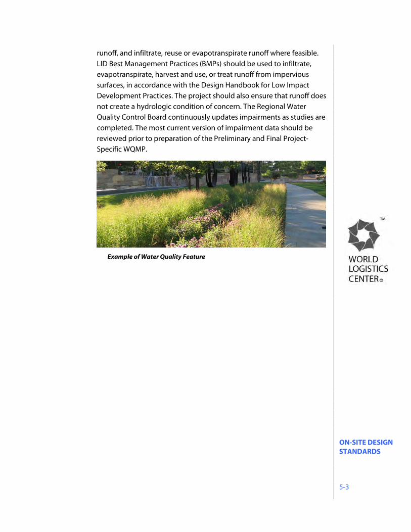
ON-SITE DESIGN STANDARDS 5-3
runoff, and infiltrate, reuse or evapotranspirate runoff where feasible. LID Best Management Practices (BMPs) should be used to infiltrate, evapotranspirate, harvest and use, or treat runoff from impervious surfaces, in accordance with the Design Handbook for Low Impact Development Practices. The project should also ensure that runoff does not create a hydrologic condition of concern. The Regional Water Quality Control Board continuously updates impairments as studies are completed. The most current version of impairment data should be reviewed prior to preparation of the Preliminary and Final Project-Specific WQMP.
Example of Water Quality Feature
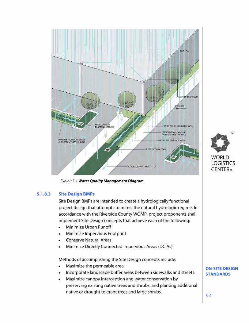
ON-SITE DESIGN STANDARDS 5-4
5.1.8.3 Site Design BMPs Site Design BMPs are intended to create a hydrologically functional project design that attempts to mimic the natural hydrologic regime. In accordance with the Riverside County WQMP, project proponents shall implement Site Design concepts that achieve each of the following: Minimize Urban Runoff Minimize Impervious Footprint Conserve Natural Areas Minimize Directly Connected Impervious Areas (DCIAs)
Methods of accomplishing the Site Design concepts include: Maximize the permeable area. Incorporate landscape buffer areas between sidewalks and streets. Maximize canopy interception and water conservation by
preserving existing native trees and shrubs, and planting additional native or drought tolerant trees and large shrubs.
Exhibit 5-1 Water Quality Management Diagram
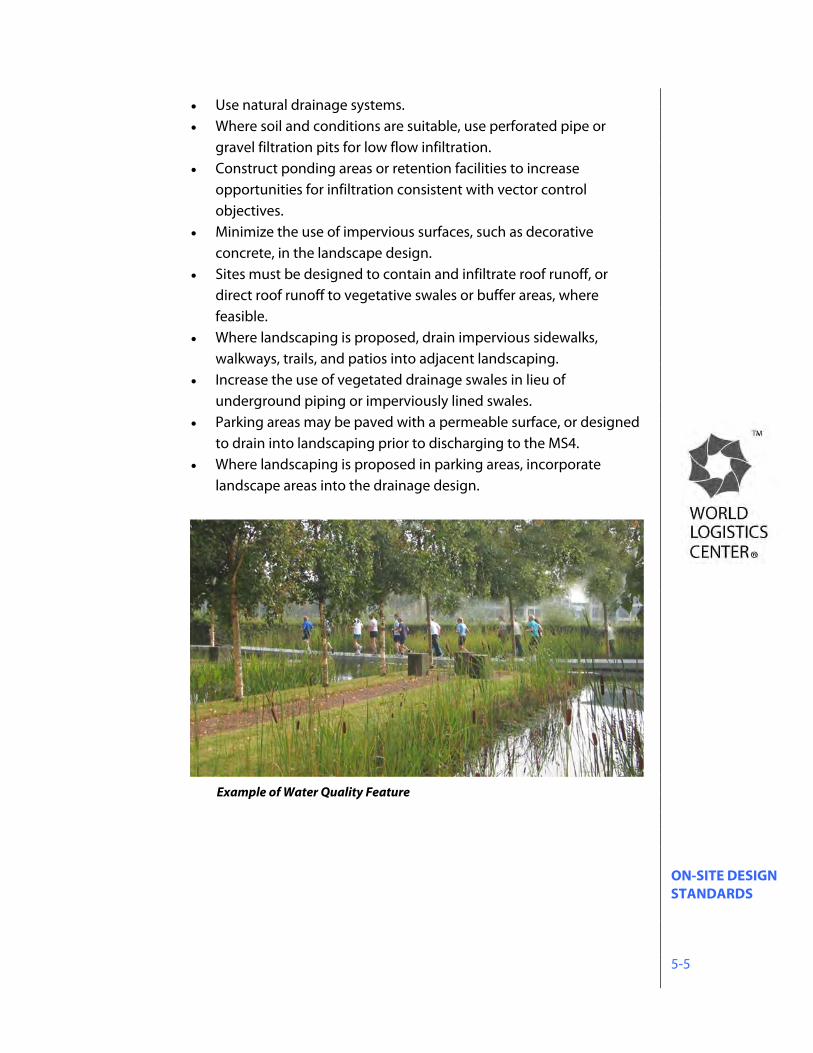
ON-SITE DESIGN STANDARDS 5-5
Use natural drainage systems. Where soil and conditions are suitable, use perforated pipe or
gravel filtration pits for low flow infiltration. Construct ponding areas or retention facilities to increase
opportunities for infiltration consistent with vector control objectives.
Minimize the use of impervious surfaces, such as decorative concrete, in the landscape design.
Sites must be designed to contain and infiltrate roof runoff, or direct roof runoff to vegetative swales or buffer areas, where feasible.
Where landscaping is proposed, drain impervious sidewalks, walkways, trails, and patios into adjacent landscaping.
Increase the use of vegetated drainage swales in lieu of underground piping or imperviously lined swales.
Parking areas may be paved with a permeable surface, or designed to drain into landscaping prior to discharging to the MS4.
Where landscaping is proposed in parking areas, incorporate landscape areas into the drainage design.
Example of Water Quality Feature
ON-SITE DESIGN STANDARDS 5-6
5.1.8.4 Source Control BMPs Source Control BMPs are also required to be implemented for each project as part of the Final WQMP. Source Control BMPs are those measures which can be taken to eliminate the presence of pollutants through prevention. Such measures can be both non-structural and structural.
5.1.8.5 Treatment Control BMPs
The Treatment Control BMP strategy for the project is to select Low Impact Development (LID) BMPs that promote infiltration and evapotranspiration, including infiltration basins, bioretention facilities, and extended detention basins. Generally infiltration BMPs have advantages over other types of BMPs, including reduction of the volume and rate of runoff, as well as full treatment of all potential pollutants potentially contained in the stormwater runoff. It is recognized however that infiltration may not be feasible on sites with low infiltration rates, or located on compacted engineered fill. If the BMP is considered in a fill condition, and the infiltration surface of the BMP cannot extend down into native soils, or if the BMP is considered in a cut condition, and there is no practicable way to verify infiltration rates at the final BMP elevation, infiltration BMPs will not be used. Prior to final design, infiltration tests shall be performed within the boundaries of the proposed infiltration BMP and at the bottom elevation (infiltration surface) of the proposed infiltration BMP to
Non-structural Source Control BMPs include: Education for property owners, operators, tenants,
occupants, or employees Activity restrictions Irrigation system and landscape maintenance Common area litter control Street sweeping private streets and parking lots Drainage facility inspection and maintenance
Structural Source Control BMPs include:
Stenciling and signage Landscape and irrigation system design Protect slopes and channels Properly design fueling areas, trash storage areas,
loading docks, and outdoor material storage areas
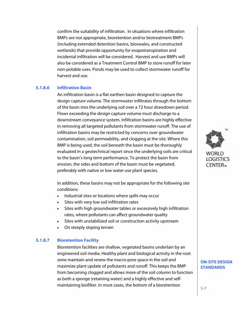
ON-SITE DESIGN STANDARDS 5-7
confirm the suitability of infiltration. In situations where infiltration BMPs are not appropriate, bioretention and/or biotreatment BMPs (including extended detention basins, bioswales, and constructed wetlands) that provide opportunity for evapotranspiration and incidental infiltration will be considered. Harvest and use BMPs will also be considered as a Treatment Control BMP to store runoff for later non-potable uses. Ponds may be used to collect stormwater runoff for harvest and use.
5.1.8.6 Infiltration Basin
An infiltration basin is a flat earthen basin designed to capture the design capture volume. The stormwater infiltrates through the bottom of the basin into the underlying soil over a 72 hour drawdown period. Flows exceeding the design capture volume must discharge to a downstream conveyance system. Infiltration basins are highly effective in removing all targeted pollutants from stormwater runoff. The use of infiltration basins may be restricted by concerns over groundwater contamination, soil permeability, and clogging at the site. Where this BMP is being used, the soil beneath the basin must be thoroughly evaluated in a geotechnical report since the underlying soils are critical to the basin’s long term performance. To protect the basin from erosion, the sides and bottom of the basin must be vegetated, preferably with native or low water use plant species.
In addition, these basins may not be appropriate for the following site conditions: Industrial sites or locations where spills may occur Sites with very low soil infiltration rates Sites with high groundwater tables or excessively high infiltration
rates, where pollutants can affect groundwater quality Sites with unstabilized soil or construction activity upstream On steeply sloping terrain
5.1.8.7 Bioretention Facility
Bioretention facilities are shallow, vegetated basins underlain by an engineered soil media. Healthy plant and biological activity in the root zone maintain and renew the macro-pore space in the soil and maximize plant update of pollutants and runoff. This keeps the BMP from becoming clogged and allows more of the soil column to function as both a sponge (retaining water) and a highly effective and self-maintaining biofilter. In most cases, the bottom of a bioretention
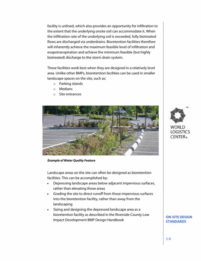
ON-SITE DESIGN STANDARDS 5-8
facility is unlined, which also provides an opportunity for infiltration to the extent that the underlying onsite soil can accommodate it. When the infiltration rate of the underlying soil is exceeded, fully biotreated flows are discharged via underdrains. Bioretention facilities therefore will inherently achieve the maximum feasible level of infiltration and evapotranspiration and achieve the minimum feasible (but highly biotreated) discharge to the storm drain system.
These facilities work best when they are designed in a relatively level area. Unlike other BMPs, bioretention facilities can be used in smaller landscape spaces on the site, such as:
o Parking islands o Medians o Site entrances
Landscape areas on the site can often be designed as bioretention facilities. This can be accomplished by: Depressing landscape areas below adjacent impervious surfaces,
rather than elevating those areas Grading the site to direct runoff from those impervious surfaces
into the bioretention facility, rather than away from the landscaping
Sizing and designing the depressed landscape area as a bioretention facility as described in the Riverside County Low Impact Development BMP Design Handbook
Example of Water Quality Feature
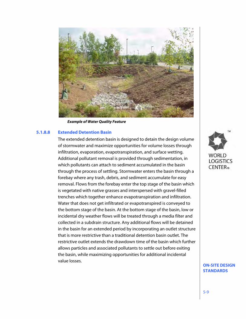
ON-SITE DESIGN STANDARDS 5-9
Example of Water Quality Feature
5.1.8.8 Extended Detention Basin
The extended detention basin is designed to detain the design volume of stormwater and maximize opportunities for volume losses through infiltration, evaporation, evapotranspiration, and surface wetting. Additional pollutant removal is provided through sedimentation, in which pollutants can attach to sediment accumulated in the basin through the process of settling. Stormwater enters the basin through a forebay where any trash, debris, and sediment accumulate for easy removal. Flows from the forebay enter the top stage of the basin which is vegetated with native grasses and interspersed with gravel-filled trenches which together enhance evapotranspiration and infiltration. Water that does not get infiltrated or evapotranspired is conveyed to the bottom stage of the basin. At the bottom stage of the basin, low or incidental dry weather flows will be treated through a media filter and collected in a subdrain structure. Any additional flows will be detained in the basin for an extended period by incorporating an outlet structure that is more restrictive than a traditional detention basin outlet. The restrictive outlet extends the drawdown time of the basin which further allows particles and associated pollutants to settle out before exiting the basin, while maximizing opportunities for additional incidental value losses.
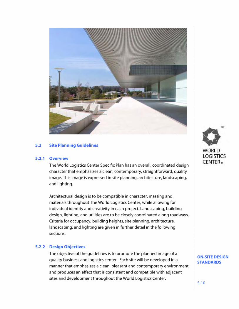
ON-SITE DESIGN STANDARDS 5-10
5.2 Site Planning Guidelines
5.2.1 Overview
The World Logistics Center Specific Plan has an overall, coordinated design character that emphasizes a clean, contemporary, straightforward, quality image. This image is expressed in site planning, architecture, landscaping, and lighting. Architectural design is to be compatible in character, massing and materials throughout The World Logistics Center, while allowing for individual identity and creativity in each project. Landscaping, building design, lighting, and utilities are to be closely coordinated along roadways. Criteria for occupancy, building heights, site planning, architecture, landscaping, and lighting are given in further detail in the following sections.
5.2.2 Design Objectives
The objective of the guidelines is to promote the planned image of a quality business and logistics center. Each site will be developed in a manner that emphasizes a clean, pleasant and contemporary environment, and produces an effect that is consistent and compatible with adjacent sites and development throughout the World Logistics Center.
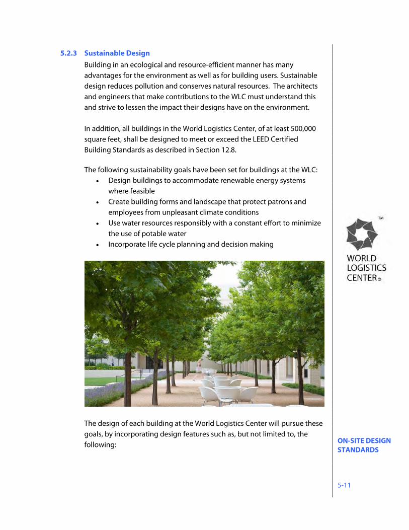
ON-SITE DESIGN STANDARDS 5-11
5.2.3 Sustainable Design Building in an ecological and resource-efficient manner has many advantages for the environment as well as for building users. Sustainable design reduces pollution and conserves natural resources. The architects and engineers that make contributions to the WLC must understand this and strive to lessen the impact their designs have on the environment. In addition, all buildings in the World Logistics Center, of at least 500,000 square feet, shall be designed to meet or exceed the LEED Certified Building Standards as described in Section 12.8.
The following sustainability goals have been set for buildings at the WLC:
Design buildings to accommodate renewable energy systems where feasible
Create building forms and landscape that protect patrons and employees from unpleasant climate conditions
Use water resources responsibly with a constant effort to minimize the use of potable water
Incorporate life cycle planning and decision making
The design of each building at the World Logistics Center will pursue these goals, by incorporating design features such as, but not limited to, the following:
ON-SITE DESIGN STANDARDS 5-12
Water conservation: Low flow faucets and fixtures Rain water collection (where practical) Native landscape Direct and capture low-use irrigation and rainfall runoff to
landscape areas
Energy conservation: Building orientation Glazing, overhangs, and landscaping to capture and control natural
daylight High performance glazing Use of atriums, skylights and internal courtyards to provide
additional daylighting
Natural resource conservation: Use of renewable materials where feasible The use of building materials with recycled content where feasible
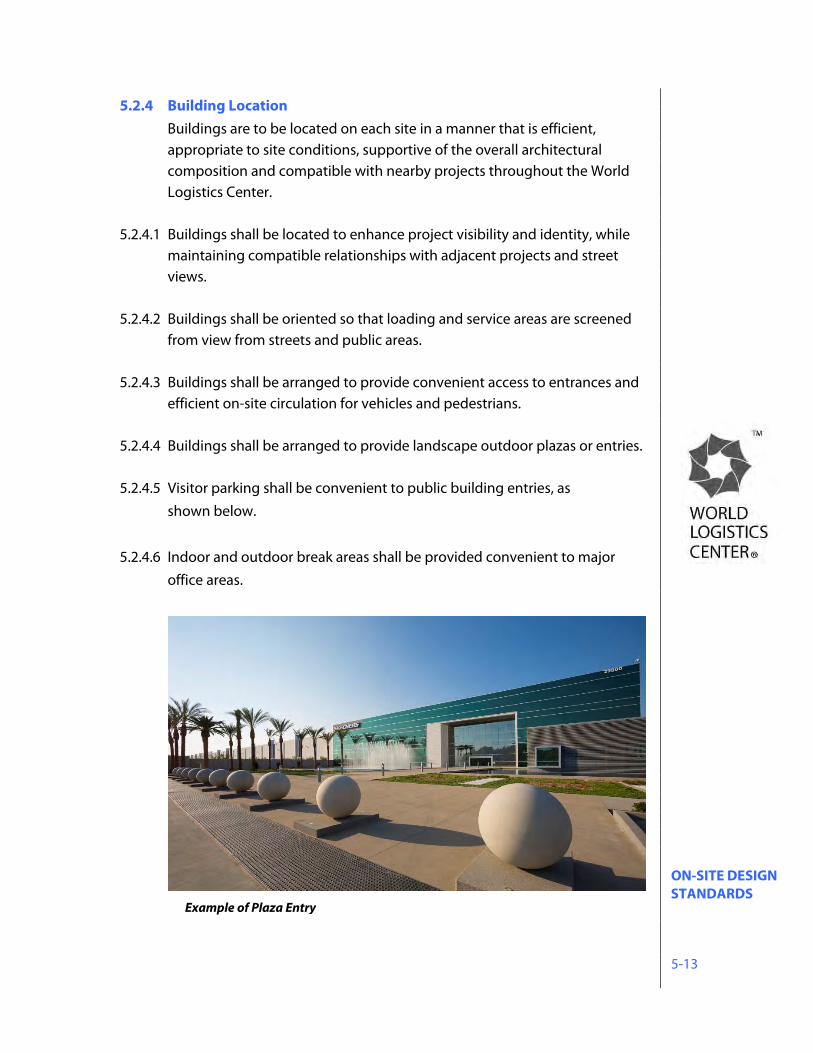
ON-SITE DESIGN STANDARDS 5-13
5.2.4 Building Location Buildings are to be located on each site in a manner that is efficient, appropriate to site conditions, supportive of the overall architectural composition and compatible with nearby projects throughout the World Logistics Center.
5.2.4.1 Buildings shall be located to enhance project visibility and identity, while maintaining compatible relationships with adjacent projects and street views.
5.2.4.2 Buildings shall be oriented so that loading and service areas are screened from view from streets and public areas.
5.2.4.3 Buildings shall be arranged to provide convenient access to entrances and efficient on-site circulation for vehicles and pedestrians.
5.2.4.4 Buildings shall be arranged to provide landscape outdoor plazas or entries. 5.2.4.5 Visitor parking shall be convenient to public building entries, as
shown below.
5.2.4.6 Indoor and outdoor break areas shall be provided convenient to major office areas.
Example of Plaza Entry
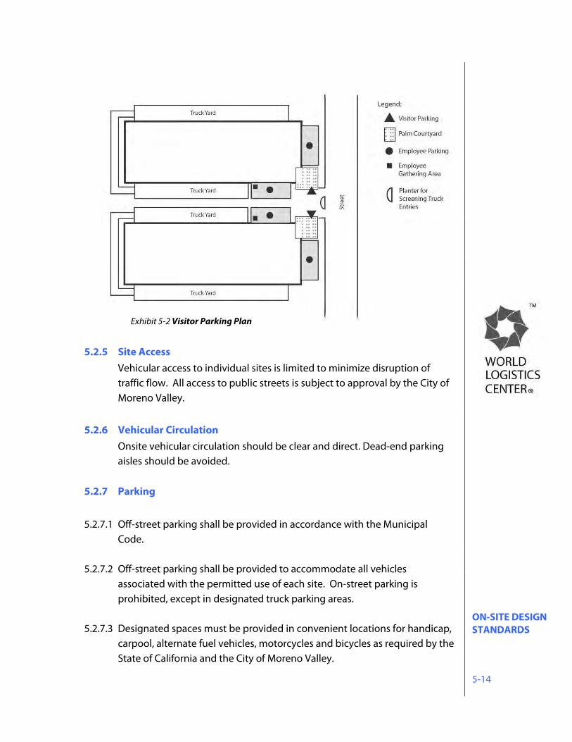
ON-SITE DESIGN STANDARDS 5-14
5.2.5 Site Access
Vehicular access to individual sites is limited to minimize disruption of traffic flow. All access to public streets is subject to approval by the City of Moreno Valley.
5.2.6 Vehicular Circulation
Onsite vehicular circulation should be clear and direct. Dead-end parking aisles should be avoided.
5.2.7 Parking 5.2.7.1 Off-street parking shall be provided in accordance with the Municipal
Code. 5.2.7.2 Off-street parking shall be provided to accommodate all vehicles
associated with the permitted use of each site. On-street parking is prohibited, except in designated truck parking areas.
5.2.7.3 Designated spaces must be provided in convenient locations for handicap, carpool, alternate fuel vehicles, motorcycles and bicycles as required by the State of California and the City of Moreno Valley.
Exhibit 5-2 Visitor Parking Plan
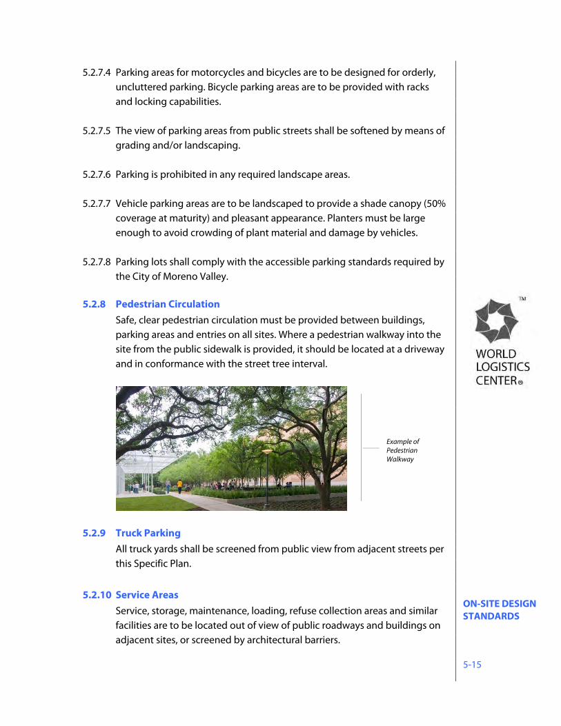
ON-SITE DESIGN STANDARDS 5-15
5.2.7.4 Parking areas for motorcycles and bicycles are to be designed for orderly, uncluttered parking. Bicycle parking areas are to be provided with racks and locking capabilities.
5.2.7.5 The view of parking areas from public streets shall be softened by means of grading and/or landscaping.
5.2.7.6 Parking is prohibited in any required landscape areas.
5.2.7.7 Vehicle parking areas are to be landscaped to provide a shade canopy (50% coverage at maturity) and pleasant appearance. Planters must be large enough to avoid crowding of plant material and damage by vehicles.
5.2.7.8 Parking lots shall comply with the accessible parking standards required by the City of Moreno Valley.
5.2.8 Pedestrian Circulation
Safe, clear pedestrian circulation must be provided between buildings, parking areas and entries on all sites. Where a pedestrian walkway into the site from the public sidewalk is provided, it should be located at a driveway and in conformance with the street tree interval.
5.2.9 Truck Parking
All truck yards shall be screened from public view from adjacent streets per this Specific Plan.
5.2.10 Service Areas
Service, storage, maintenance, loading, refuse collection areas and similar facilities are to be located out of view of public roadways and buildings on adjacent sites, or screened by architectural barriers.
Example of Pedestrian Walkway
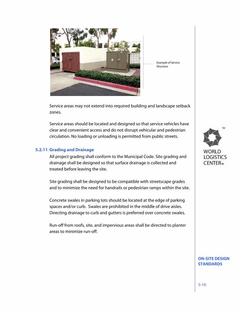
ON-SITE DESIGN STANDARDS 5-16
Service areas may not extend into required building and landscape setback zones.
Service areas should be located and designed so that service vehicles have clear and convenient access and do not disrupt vehicular and pedestrian circulation. No loading or unloading is permitted from public streets.
5.2.11 Grading and Drainage
All project grading shall conform to the Municipal Code. Site grading and drainage shall be designed so that surface drainage is collected and treated before leaving the site. Site grading shall be designed to be compatible with streetscape grades and to minimize the need for handrails or pedestrian ramps within the site. Concrete swales in parking lots should be located at the edge of parking spaces and/or curb. Swales are prohibited in the middle of drive aisles. Directing drainage to curb and gutters is preferred over concrete swales. Run-off from roofs, site, and impervious areas shall be directed to planter areas to minimize run-off.
Example of Service Structure
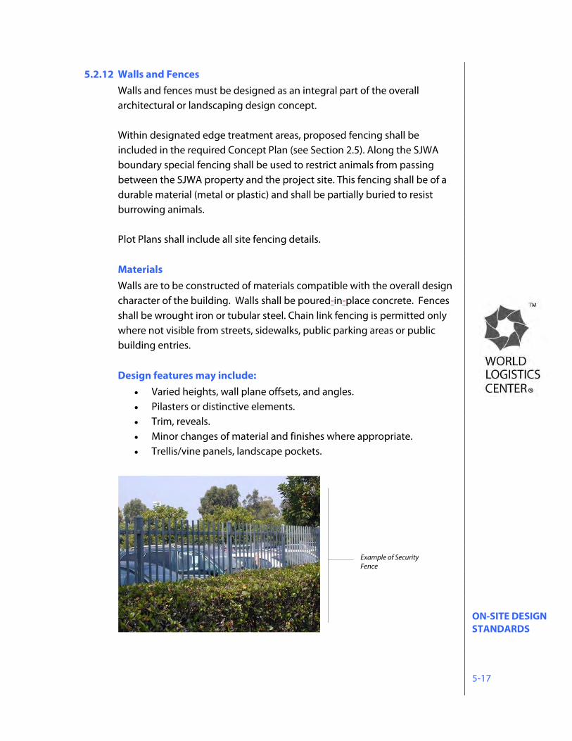
ON-SITE DESIGN STANDARDS 5-17
5.2.12 Walls and Fences Walls and fences must be designed as an integral part of the overall architectural or landscaping design concept. Within designated edge treatment areas, proposed fencing shall be included in the required Concept Plan (see Section 2.5). Along the SJWA boundary special fencing shall be used to restrict animals from passing between the SJWA property and the project site. This fencing shall be of a durable material (metal or plastic) and shall be partially buried to resist burrowing animals. Plot Plans shall include all site fencing details. Materials Walls are to be constructed of materials compatible with the overall design character of the building. Walls shall be poured-in-place concrete. Fences shall be wrought iron or tubular steel. Chain link fencing is permitted only where not visible from streets, sidewalks, public parking areas or public building entries. Design features may include:
Varied heights, wall plane offsets, and angles. Pilasters or distinctive elements. Trim, reveals. Minor changes of material and finishes where appropriate. Trellis/vine panels, landscape pockets.
Example of Security Fence
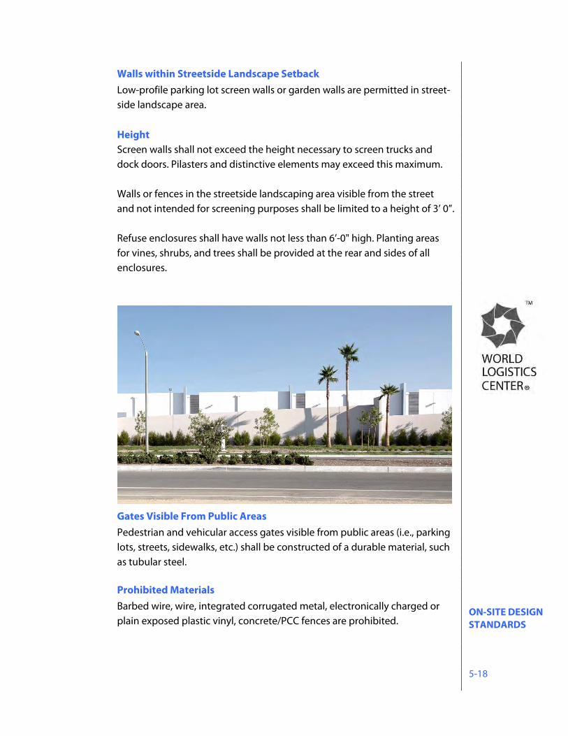
ON-SITE DESIGN STANDARDS 5-18
Walls within Streetside Landscape Setback Low-profile parking lot screen walls or garden walls are permitted in street-side landscape area.
Height Screen walls shall not exceed the height necessary to screen trucks and dock doors. Pilasters and distinctive elements may exceed this maximum.
Walls or fences in the streetside landscaping area visible from the street and not intended for screening purposes shall be limited to a height of 3’ 0”. Refuse enclosures shall have walls not less than 6’-0" high. Planting areas for vines, shrubs, and trees shall be provided at the rear and sides of all enclosures.
Gates Visible From Public Areas Pedestrian and vehicular access gates visible from public areas (i.e., parking lots, streets, sidewalks, etc.) shall be constructed of a durable material, such as tubular steel.
Prohibited Materials Barbed wire, wire, integrated corrugated metal, electronically charged or plain exposed plastic vinyl, concrete/PCC fences are prohibited.
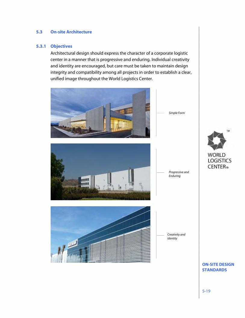
ON-SITE DESIGN STANDARDS 5-19
5.3 On-site Architecture 5.3.1 Objectives
Architectural design should express the character of a corporate logistic center in a manner that is progressive and enduring. Individual creativity and identity are encouraged, but care must be taken to maintain design integrity and compatibility among all projects in order to establish a clear, unified image throughout the World Logistics Center.
Creativity and Identity
Progressive and Enduring
Simple Form
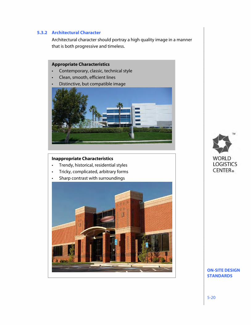
ON-SITE DESIGN STANDARDS 5-20
5.3.2 Architectural Character Architectural character should portray a high quality image in a manner that is both progressive and timeless.
Appropriate Characteristics • Contemporary, classic, technical style • Clean, smooth, efficient lines • Distinctive, but compatible image
Inappropriate Characteristics • Trendy, historical, residential styles • Tricky, complicated, arbitrary forms • Sharp contrast with surroundings
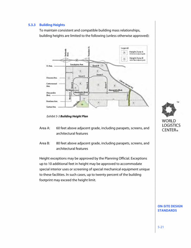
ON-SITE DESIGN STANDARDS 5-21
5.3.3 Building Heights To maintain consistent and compatible building mass relationships, building heights are limited to the following (unless otherwise approved):
Area A: 60 feet above adjacent grade, including parapets, screens, and architectural features
Area B: 80 feet above adjacent grade, including parapets, screens, and
architectural features
Height exceptions may be approved by the Planning Official. Exceptions up to 10 additional feet in height may be approved to accommodate special interior uses or screening of special mechanical equipment unique to these facilities. In such cases, up to twenty percent of the building footprint may exceed the height limit.
Exhibit 5-3 Building Height Plan
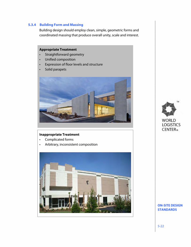
ON-SITE DESIGN STANDARDS 5-22
5.3.4 Building Form and Massing Building design should employ clean, simple, geometric forms and coordinated massing that produce overall unity, scale and interest.
Appropriate Treatment • Straightforward geometry • Unified composition • Expression of floor levels and structure • Solid parapets
Inappropriate Treatment • Complicated forms • Arbitrary, inconsistent composition
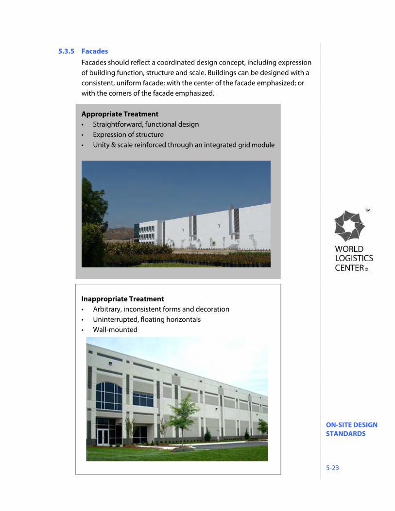
ON-SITE DESIGN STANDARDS 5-23
5.3.5 Facades Facades should reflect a coordinated design concept, including expression of building function, structure and scale. Buildings can be designed with a consistent, uniform facade; with the center of the facade emphasized; or with the corners of the facade emphasized. Appropriate Treatment • Straightforward, functional design • Expression of structure • Unity & scale reinforced through an integrated grid module
Inappropriate Treatment • Arbitrary, inconsistent forms and decoration • Uninterrupted, floating horizontals • Wall-mounted
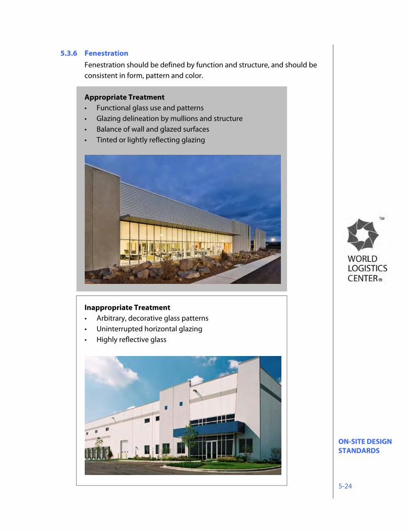
ON-SITE DESIGN STANDARDS 5-24
5.3.6 Fenestration Fenestration should be defined by function and structure, and should be consistent in form, pattern and color. Appropriate Treatment • Functional glass use and patterns • Glazing delineation by mullions and structure • Balance of wall and glazed surfaces • Tinted or lightly reflecting glazing
Inappropriate Treatment • Arbitrary, decorative glass patterns • Uninterrupted horizontal glazing • Highly reflective glass
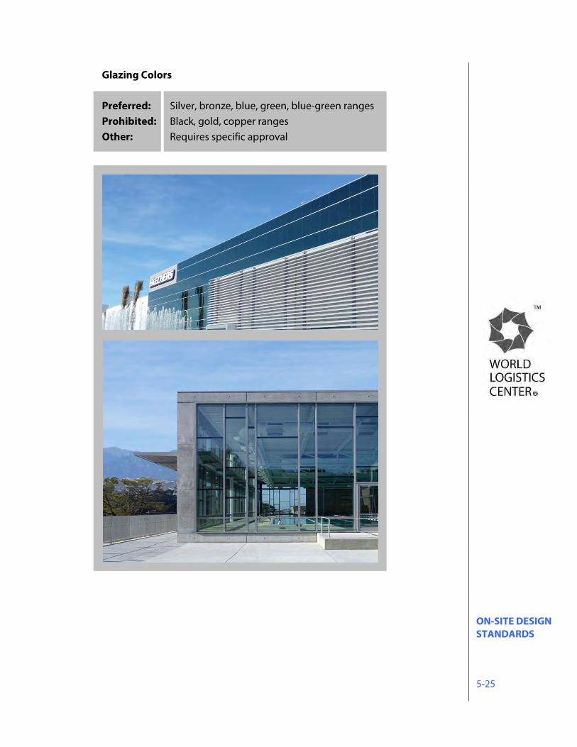
ON-SITE DESIGN STANDARDS 5-25
Glazing Colors
Preferred: Silver, bronze, blue, green, blue-green ranges Prohibited: Black, gold, copper ranges Other: Requires specific approval
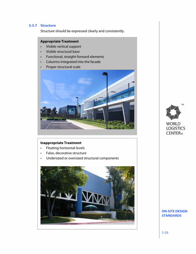
ON-SITE DESIGN STANDARDS 5-26
5.3.7 Structure Structure should be expressed clearly and consistently. Appropriate Treatment • Visible vertical support • Visible structural base • Functional, straight-forward elements • Columns integrated into the facade • Proper structural scale
Inappropriate Treatment • Floating horizontal levels • False, decorative structure • Undersized or oversized structural components
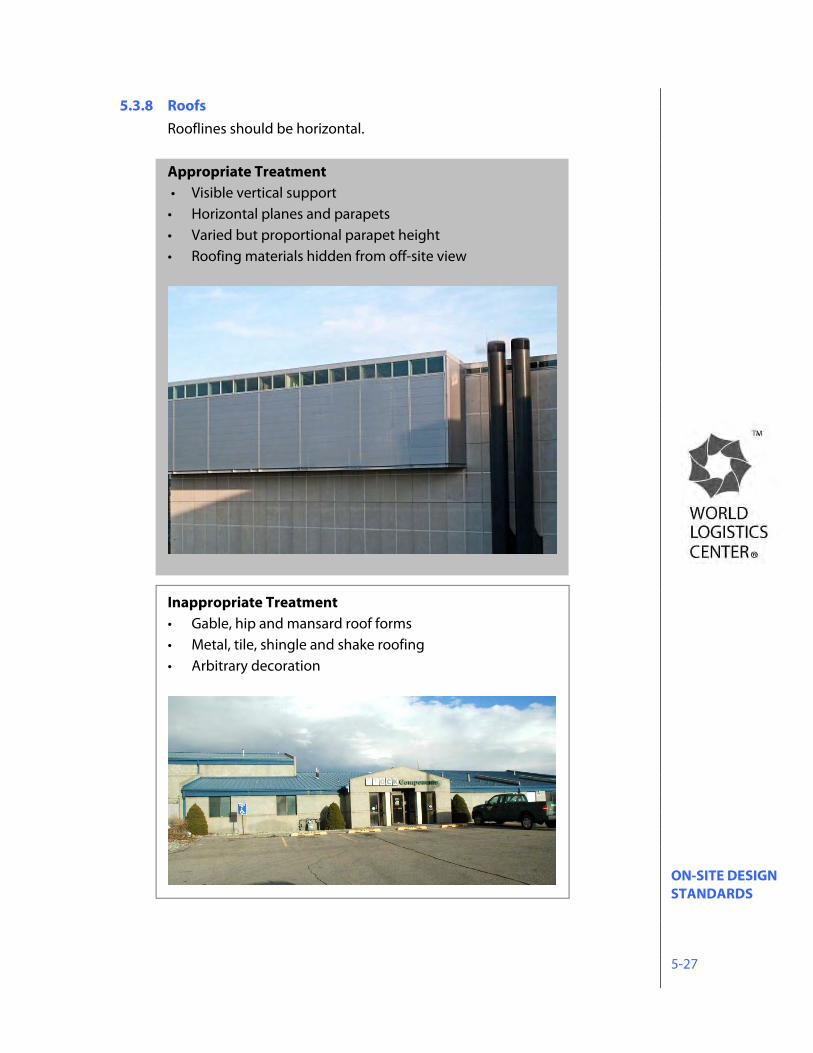
ON-SITE DESIGN STANDARDS 5-27
5.3.8 Roofs Rooflines should be horizontal. Appropriate Treatment • Visible vertical support • Horizontal planes and parapets • Varied but proportional parapet height • Roofing materials hidden from off-site view
Inappropriate Treatment • Gable, hip and mansard roof forms • Metal, tile, shingle and shake roofing • Arbitrary decoration
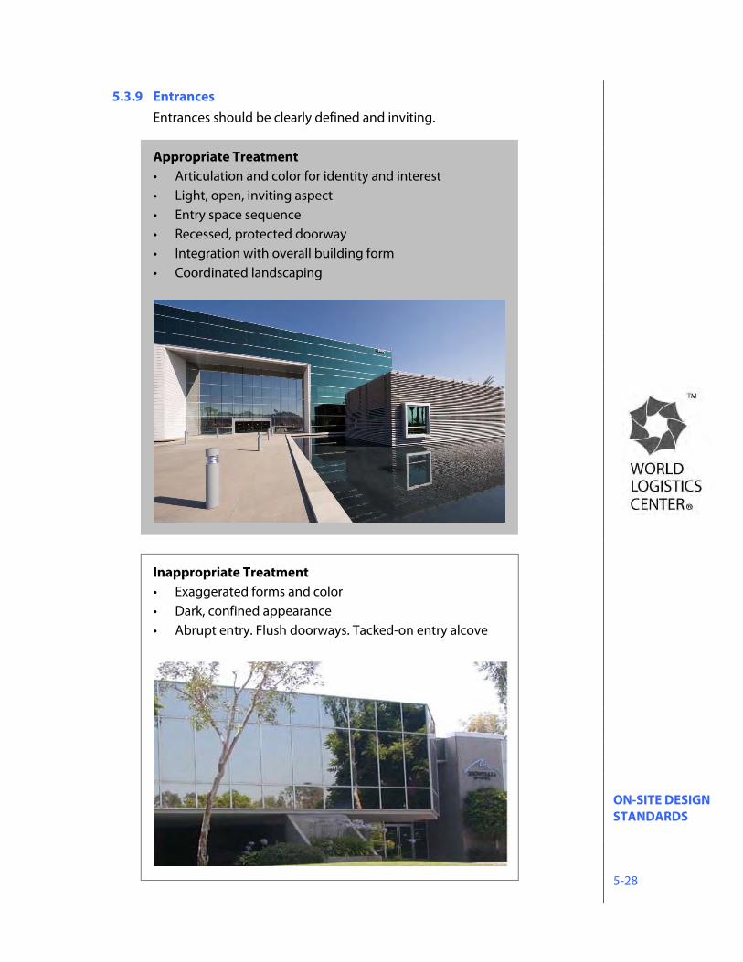
ON-SITE DESIGN STANDARDS 5-28
5.3.9 Entrances Entrances should be clearly defined and inviting. Appropriate Treatment • Articulation and color for identity and interest • Light, open, inviting aspect • Entry space sequence • Recessed, protected doorway • Integration with overall building form • Coordinated landscaping
Inappropriate Treatment • Exaggerated forms and color • Dark, confined appearance • Abrupt entry. Flush doorways. Tacked-on entry alcove
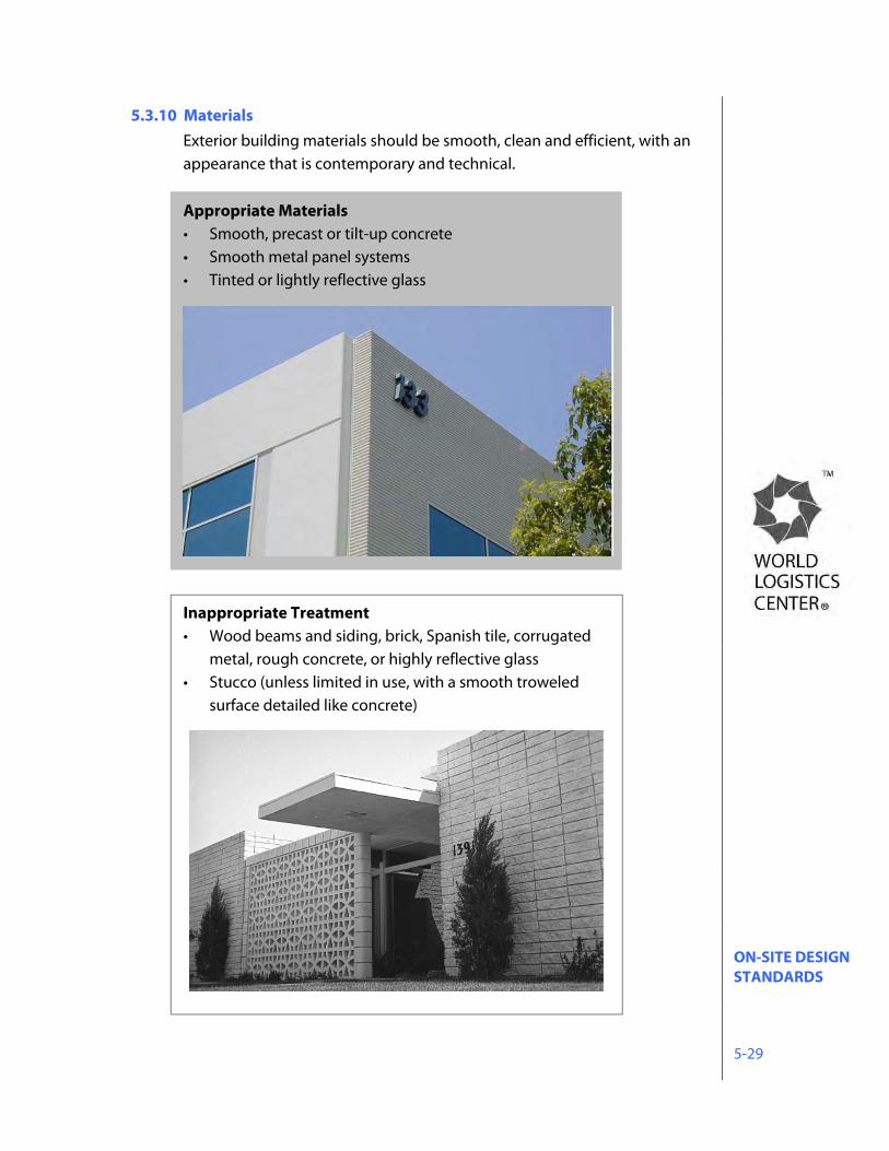
ON-SITE DESIGN STANDARDS 5-29
5.3.10 Materials Exterior building materials should be smooth, clean and efficient, with an appearance that is contemporary and technical. Appropriate Materials • Smooth, precast or tilt-up concrete • Smooth metal panel systems • Tinted or lightly reflective glass
Inappropriate Treatment • Wood beams and siding, brick, Spanish tile, corrugated
metal, rough concrete, or highly reflective glass • Stucco (unless limited in use, with a smooth troweled
surface detailed like concrete)
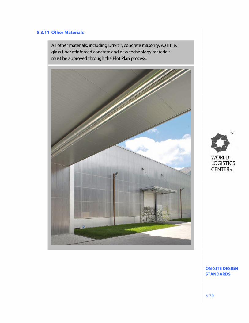
ON-SITE DESIGN STANDARDS 5-30
5.3.11 Other Materials All other materials, including Drivit ®, concrete masonry, wall tile, glass fiber reinforced concrete and new technology materials must be approved through the Plot Plan process.
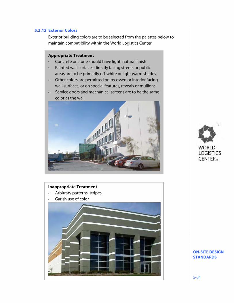
ON-SITE DESIGN STANDARDS 5-31
5.3.12 Exterior Colors Exterior building colors are to be selected from the palettes below to maintain compatibility within the World Logistics Center. Appropriate Treatment • Concrete or stone should have light, natural finish • Painted wall surfaces directly facing streets or public
areas are to be primarily off-white or light warm shades • Other colors are permitted on recessed or interior facing
wall surfaces, or on special features, reveals or mullions • Service doors and mechanical screens are to be the same
color as the wall
Inappropriate Treatment • Arbitrary patterns, stripes • Garish use of color
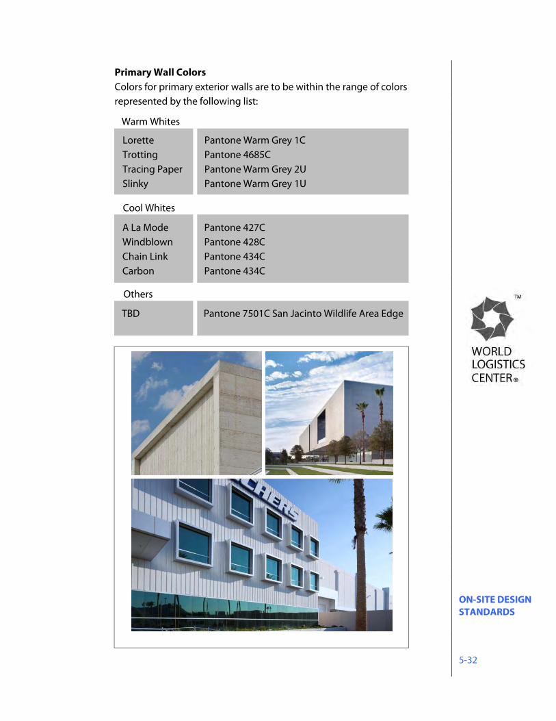
ON-SITE DESIGN STANDARDS 5-32
Primary Wall Colors Colors for primary exterior walls are to be within the range of colors represented by the following list:
Lorette Pantone Warm Grey 1CTrotting Pantone 4685C Tracing Paper Pantone Warm Grey 2U Slinky Pantone Warm Grey 1U
A La Mode Pantone 427CWindblown Pantone 428C Chain Link Pantone 434C Carbon Pantone 434C
Warm Whites
Cool Whites
TBD Pantone 7501C San Jacinto Wildlife Area Edge
Others
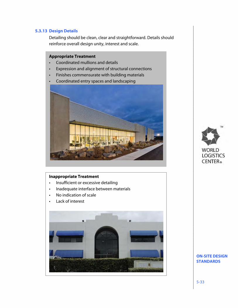
ON-SITE DESIGN STANDARDS 5-33
5.3.13 Design Details Detailing should be clean, clear and straightforward. Details should reinforce overall design unity, interest and scale. Appropriate Treatment • Coordinated mullions and details • Expression and alignment of structural connections • Finishes commensurate with building materials • Coordinated entry spaces and landscaping
Inappropriate Treatment • Insufficient or excessive detailing • Inadequate interface between materials • No indication of scale • Lack of interest
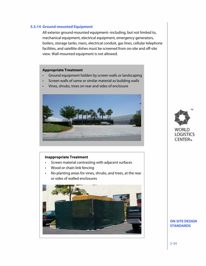
ON-SITE DESIGN STANDARDS 5-34
5.3.14 Ground-mounted Equipment All exterior ground-mounted equipment--including, but not limited to, mechanical equipment, electrical equipment, emergency generators, boilers, storage tanks, risers, electrical conduit, gas lines, cellular telephone facilities, and satellite dishes must be screened from on-site and off-site view. Wall-mounted equipment is not allowed. Appropriate Treatment • Ground equipment hidden by screen walls or landscaping • Screen walls of same or similar material as building walls • Vines, shrubs, trees on rear and sides of enclosure
Inappropriate Treatment • Screen material contrasting with adjacent surfaces • Wood or chain link fencing • No planting areas for vines, shrubs, and trees, at the rear
or sides of walled enclosures
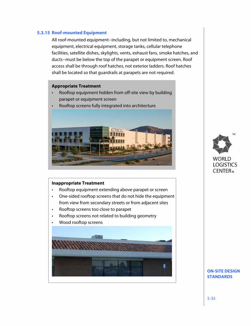
ON-SITE DESIGN STANDARDS 5-35
5.3.15 Roof-mounted Equipment All roof-mounted equipment--including, but not limited to, mechanical equipment, electrical equipment, storage tanks, cellular telephone facilities, satellite dishes, skylights, vents, exhaust fans, smoke hatches, and ducts--must be below the top of the parapet or equipment screen. Roof access shall be through roof hatches, not exterior ladders. Roof hatches shall be located so that guardrails at parapets are not required. Appropriate Treatment • Rooftop equipment hidden from off-site view by building
parapet or equipment screen • Rooftop screens fully integrated into architecture
Inappropriate Treatment • Rooftop equipment extending above parapet or screen • One-sided rooftop screens that do not hide the equipment
from view from secondary streets or from adjacent sites • Rooftop screens too close to parapet • Rooftop screens not related to building geometry • Wood rooftop screens
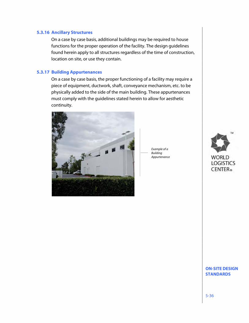
ON-SITE DESIGN STANDARDS 5-36
5.3.16 Ancillary Structures On a case by case basis, additional buildings may be required to house functions for the proper operation of the facility. The design guidelines found herein apply to all structures regardless of the time of construction, location on site, or use they contain.
5.3.17 Building Appurtenances On a case by case basis, the proper functioning of a facility may require a piece of equipment, ductwork, shaft, conveyance mechanism, etc. to be physically added to the side of the main building. These appurtenances must comply with the guidelines stated herein to allow for aesthetic continuity.
Example of a Building Appurtenance
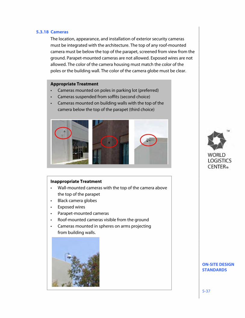
ON-SITE DESIGN STANDARDS 5-37
5.3.18 Cameras The location, appearance, and installation of exterior security cameras must be integrated with the architecture. The top of any roof-mounted camera must be below the top of the parapet, screened from view from the ground. Parapet-mounted cameras are not allowed. Exposed wires are not allowed. The color of the camera housing must match the color of the poles or the building wall. The color of the camera globe must be clear.
Appropriate Treatment • Cameras mounted on poles in parking lot (preferred) • Cameras suspended from soffits (second choice) • Cameras mounted on building walls with the top of the
camera below the top of the parapet (third choice)
Inappropriate Treatment • Wall-mounted cameras with the top of the camera above
the top of the parapet • Black camera globes • Exposed wires • Parapet-mounted cameras • Roof-mounted cameras visible from the ground • Cameras mounted in spheres on arms projecting
from building walls.
ON-SITE DESIGN STANDARDS 5-38
5.4 On-site Landscaping 5.4.1 Objectives
Landscaping is an important element contributing to the identity and unity of the World Logistics Center. As such, all landscaping for the project shall: • Promote a pleasant, distinctive, corporate environment, • Augment internal cohesion and continuity within the World Logistics
Center, • Enhance the structured urban design concept of the World Logistics
Center, and • Promote water conservation. The landscaping design concept is focused toward: • Providing a clean, contemporary visual appearance, • Coordinating the landscaping treatment along freeway and surface streets
to emphasize the circulation system, • Coordinating streetscapes within the World Logistics Center to unify its
general appearance, and • Coordinating on-site landscaping design continuity among individual
development sites within the World Logistics Center. The following guidelines present parameters for general landscape design, water conservation, streetscapes, and on-site landscaping.
5.4.2 Water Conservation Measures The World Logistics Center employs an aggressive approach to water
conservation. Every element of the landscape program has been evaluated to determine how to achieve the project’s landscape goals while consuming as little water as possible. From the formulation of the overall landscape concept, through each level of the design process, to the day-to-day maintenance practices of the installed materials, conservation of limited water resources is a constant primary focus.
This approach represents a significant departure from conventional
development strategies, particularly in a large-scale master-planned logistics campus setting. Most of the project will be designed without mechanical irrigation, relying instead on maximizing the collection and harvesting of runoff to be directed to landscape areas. This program will
ON-SITE DESIGN STANDARDS 5-39
require the use of carefully selected plant types, complex drainage designs, intricate planting techniques, and specialized maintenance programs.
Implementation of these new design concepts will result in a landscape
aesthetic that will appear different than traditional landscape treatments. At installation, plant material will be smaller and with greater spacing in order to match available water to the needs of specific plants. As landscaping gets established, coverage may take longer, certain plants will appear dry as they go through dormant periods, and in some cases supplemental watering may be necessary in periods of severe drought. At maturity, the landscaping at the WLC project will provide a strong, clean, simple design element, demonstrating the WLC’s commitment to the creation of a successful logistics campus in a sustainable environment.
The landscape program will incorporate the following design elements and
practices to minimize the use of limited water resources: Project Design:
Design project so that pads, streets and other paved areas drain to landscape areas, medians and parkways,
Maximize water harvesting, retention and treatment techniques throughout the project
Utilize zero-inch curb design to facilitate rainwater runoff from road surfaces
Direct rooftop and parking area runoff to bioswales, basins or landscaped areas
Landscape Design: Develop watershed areas for the project areas in order to manage
water harvesting and distribution Calculate estimated runoff from roofs and paved areas to manage
water harvesting and retention practices Conduct site-specific analyses of seasonal weather patterns, rain
patterns, soils and drainage, grades and slopes, macro and micro climates, solar exposure, prevailing wind conditions, historical evapotranspiration rates and weather station (CIMIS) data
Design to meet peak moisture demand of all plant materials within design zones and avoid flow rates that exceed infiltration rate of soil
Maximize the use of drought tolerant plant species Select plant palettes tolerant of periodic inundation from storm water
runoff
ON-SITE DESIGN STANDARDS 5-40
Calculate optimum spacing of plants to avoid overcrowding and need for excessive irrigation.
Select container plant sizes are to achieve a high root to canopy ratio; no root bound or oversized plants
Construction: Grade all planting areas to control high intensity rainfall and runoff
episodes. Provide riprap at downspouts; create multiple watersheds to disperse water flow. Use surface mulch and straw wattles.
Grade all planting areas to provide for the retention and infiltration of water to each plant.
Provide soil amendment to plant pits based upon soil laboratory test results and landscape species.
Construct planting pits to be 3-4 times the diameter of the planting container and twice as deep.
Provide a pre-hydration program prior to planting installation to reflect climate and soil conditions.
Cover all planting areas with a combination of organic and inorganic mulches to be used along with pre-emergent herbicide treatment to control weed growth and soil erosion.
Install soil moisture sensors in strategic planting zones. Require certification that the irrigation system was installed and
operates as designed, and conduct a post-installation audit of actual water consumption
Provide for supplemental irrigation on an as-needed basis, such as supply lines and valves, quick-connect couplers or water truck service.
Maintenance: Establish maintenance guidelines to specify actions to replace dead
plants, replenish surface mulch, and remove trash and weeds. Regularly monitor all landscaped areas and make adjustments as
necessary to assure the health of planted materials and progress toward meeting the project’s landscape goals.
Where irrigation is provided: Use planting zones coordinated according to plant type, climatic
exposure, soil condition and slope to facilitate use of zoned irrigation systems Use reclaimed water systems if available and practical,
Use best available irrigation technology to maximize efficient use of water, including moisture sensors, multi-program electronic timers, rain shutoff devices, remote control valves, drip systems, backflow preventers, pressure reducing valves and precipitation-rated sprinkler heads,
Use gate valves to isolate and shut down mainline breaks,
ON-SITE DESIGN STANDARDS 5-41
Use wind shut-off sensors for the irrigation controllers, Design irrigation systems to prevent discharge onto non-landscaped
areas or adjacent properties, Restrict irrigation cycles to operate at night when wind, evaporation
and activity are at a minimum Coverage:
At installation, plant size, density and spacing shall be as specified in approved landscape plans at 15% coverage.
Based on these design guidelines and average annual rainfall, irrigated and non-irrigated planting groups shall achieve 70% coverage after three years. Until plant material achieves full coverage, a minimum of 3” of mulch will be maintained throughout planted area, and any growth (e.g. weeds) not included in the Specific Plan plant palette shall be removed twice per year (March and September).
5.4.3 Landscape Criteria Onsite landscaping is to be coordinated in a manner that enhances overall continuity of development in the World Logistics Center, while providing for the individual identity and needs of each project within. The design must address the following criteria.
• Landscaping should be used to reinforce site planning principles, such as using trees to define parking lots and drive aisles.
• Plant materials for on-site landscaping are to be selected from the Plant Selection List, Section 5.4.4.
• Flexibility in the choice of plant materials is limited along street frontages and site perimeters to enhance landscaping coordination along common frontages, but increases toward the site interior to accommodate individual design.
• Landscaping in parking areas shall comply with the standards contained in the Municipal Code.
• Planting areas for vines, shrubs, and trees is required at the rear and sides of walled enclosures, including trash enclosures.
• Comprehensive planting, including trees, is required along all screen walls, buildings and site perimeters.
• All projects which include designated truck loading areas shall screen such areas from view from adjacent public streets and from onsite visitor parking and building entry areas (palm courts). Such screening shall be accomplished with solid block walls and opaque metal gates.
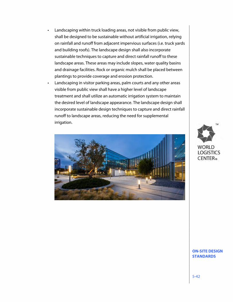
ON-SITE DESIGN STANDARDS 5-42
• Landscaping within truck loading areas, not visible from public view, shall be designed to be sustainable without artificial irrigation, relying on rainfall and runoff from adjacent impervious surfaces (i.e. truck yards and building roofs). The landscape design shall also incorporate sustainable techniques to capture and direct rainfall runoff to these landscape areas. These areas may include slopes, water quality basins and drainage facilities. Rock or organic mulch shall be placed between plantings to provide coverage and erosion protection.
• Landscaping in visitor parking areas, palm courts and any other areas visible from public view shall have a higher level of landscape treatment and shall utilize an automatic irrigation system to maintain the desired level of landscape appearance. The landscape design shall incorporate sustainable design techniques to capture and direct rainfall runoff to landscape areas, reducing the need for supplemental irrigation.
ON-SITE DESIGN STANDARDS 5-43
Palm Court
Trees (Palms – 25’ brown trunk height / All other trees – 24” box minimum) T1. Phoenix dactylifera: Date Palm T2. See section 5.4.4 for plant list Shrubs / Groundcover (1 gallon minimum) S1. Muhlenbergia rigens: Deer Grass S2. See section 5.4.4 for plant list
Not to scale | This exhibit is a graphic representation of a conceptual design at maturity.
ON-SITE DESIGN STANDARDS 5-44
5.4.4 On-site Landscape Planting All trees to be 15 gallon, minimum, unless otherwise noted. Trees Acacia aneura Mulga Acacia farnesiana Sweet Acacia Caesalpinia cacalaco Cascalote Celtis occidentalis Common Hackberry Cercidium ‘Desert Museum’ Desert Museum Palo Verde Chilopsis linearis Desert Willow Cupressus sempervirens Italian Cypress Ebenopsis ebano Texas Ebony Olea europaea Olive Phoenix dactylifera Date Palm Pinus brutia var. Eldarica Afgan Pine Pinus halepensis Aleppo Pine Populus Fremontii Cottonweed Tree Prosopis alba Argentine Mesquite Prosopis chilensis Chilean Mesquite Prosopis glandulosa Texas Honey Mesquite Prosopis glandulosa 'Maverick' Thornless Texas Honey Mesquite Schinus mollei California Pepper Tristania conferta Brisbane Box Washingtonia filifera California Fan Palm Washingtonia robusta Mexican Fan Palm Shrubs / Groundcover Abutilon palmeri Indian Mallow Acacia greggii Catclaw Acacia Acacia redolens 'Desert Carpet' Spreading Acacia 'Desert Carpet' Aloe spp. Aloe Atriplex canescens Four Wing Saltbush Atriplex lentiformis Quail Bush Baccharis sarothroides Desert Broom Baccharis ‘Starn’ Coyote Bush Caesalpina pulcherrima Redbird of Paradise Calliandra californica Baja Fairy Duster Celtis pallida Desert Hackberry Cordia boissieri Texas Olive Dasylirion wheeleri Desert Spoon Encelia farinosa Desert Encelia Fallugia paradoxa Apache Plume Hyptis emoryi Desert Lavender Isomeris arborea Bladderpod Justicia californica Chuparosa Leucophyllum texanum Texas Ranger Lycium andersonii Anderson Lycium
ON-SITE DESIGN STANDARDS 5-45
Rhus ovata Sugar Bush Salvia greggii Autumn Sage Senna nemophila Desert Cassia Senna phyllodinea Silver Cassia Simmondsia chinensis Jojoba Perennials and Grasses Asclepias subulata Desert Milkweed Baileya multiradiada Desert Marigold Eriogonum fasciculatum Common Buckwheat Penstemon eatoni Firecracker Penstemon Penstemon parryi Parry Penstemon Sphaeralcea ambigua Desert Globe Mallow Muhlenbergia rigens Deer Grass Nolina parryi Parry Beargrass
ON-SITE DESIGN STANDARDS 5-46
5.4.5 Minimum Landscape Areas If parking or access drives are located between any building and a public street frontage, a 15-foot minimum landscaping area is required between the parking or drive aisle and the building. On other sides of the building, a 10-foot minimum landscaping area is required between the parking or drive aisle and the building, except in loading areas.
1. A minimum landscape zone 15 feet is required along building perimeters facing a roadway frontage.
2. A minimum landscape zone of 10 feet is required along all other building perimeters except loading areas.
3. A minimum landscape zone of 5 feet is required along all internal property lines.
4. A minimum flat landscape zone of 8 feet is required next to screen walls facing the street.
Note: If perpendicular parking spaces are located adjacent to the minimum landscape zone, then a 2'-6" minimum parking overhang is required in addition to the above measurements (17’ 6", 12'-6" and 7'-6" respectively). Trees along screen walls, buildings and site perimeters are required at a minimum average spacing of 1 tree per 30 linear feet of perimeter, planted at 15 feet or half (1/2) the tree canopy spread from the face of building.
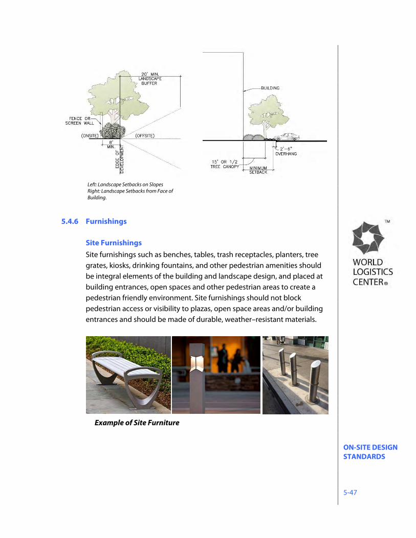
ON-SITE DESIGN STANDARDS 5-47
5.4.6 Furnishings
Site Furnishings Site furnishings such as benches, tables, trash receptacles, planters, tree grates, kiosks, drinking fountains, and other pedestrian amenities should be integral elements of the building and landscape design, and placed at building entrances, open spaces and other pedestrian areas to create a pedestrian friendly environment. Site furnishings should not block pedestrian access or visibility to plazas, open space areas and/or building entrances and should be made of durable, weather–resistant materials.
Example of Site Furniture
Left: Landscape Setbacks on Slopes Right: Landscape Setbacks from Face of Building.
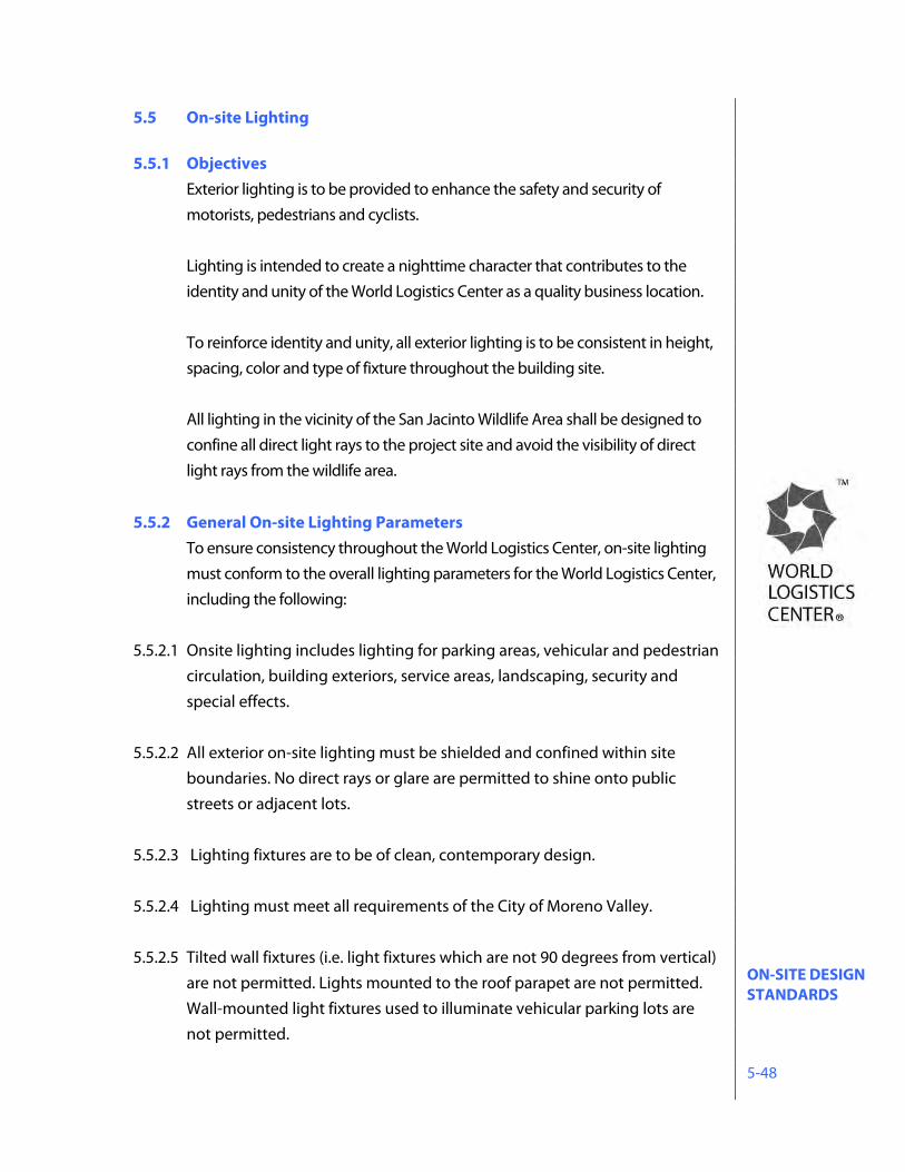
ON-SITE DESIGN STANDARDS 5-48
5.5 On-site Lighting 5.5.1 Objectives
Exterior lighting is to be provided to enhance the safety and security of motorists, pedestrians and cyclists. Lighting is intended to create a nighttime character that contributes to the identity and unity of the World Logistics Center as a quality business location. To reinforce identity and unity, all exterior lighting is to be consistent in height, spacing, color and type of fixture throughout the building site. All lighting in the vicinity of the San Jacinto Wildlife Area shall be designed to confine all direct light rays to the project site and avoid the visibility of direct light rays from the wildlife area.
5.5.2 General On-site Lighting Parameters To ensure consistency throughout the World Logistics Center, on-site lighting must conform to the overall lighting parameters for the World Logistics Center, including the following:
5.5.2.1 Onsite lighting includes lighting for parking areas, vehicular and pedestrian circulation, building exteriors, service areas, landscaping, security and special effects.
5.5.2.2 All exterior on-site lighting must be shielded and confined within site
boundaries. No direct rays or glare are permitted to shine onto public streets or adjacent lots.
5.5.2.3 Lighting fixtures are to be of clean, contemporary design. 5.5.2.4 Lighting must meet all requirements of the City of Moreno Valley. 5.5.2.5 Tilted wall fixtures (i.e. light fixtures which are not 90 degrees from vertical)
are not permitted. Lights mounted to the roof parapet are not permitted. Wall-mounted light fixtures used to illuminate vehicular parking lots are not permitted.
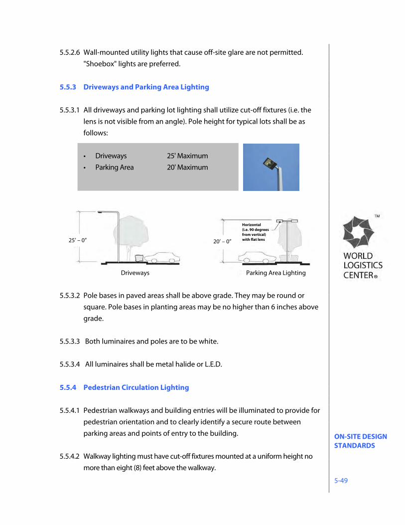
ON-SITE DESIGN STANDARDS 5-49
5.5.2.6 Wall-mounted utility lights that cause off-site glare are not permitted. "Shoebox" lights are preferred.
5.5.3 Driveways and Parking Area Lighting 5.5.3.1 All driveways and parking lot lighting shall utilize cut-off fixtures (i.e. the
lens is not visible from an angle). Pole height for typical lots shall be as follows:
• Driveways 25' Maximum • Parking Area 20' Maximum
5.5.3.2 Pole bases in paved areas shall be above grade. They may be round or
square. Pole bases in planting areas may be no higher than 6 inches above grade.
5.5.3.3 Both luminaires and poles are to be white. 5.5.3.4 All luminaires shall be metal halide or L.E.D.
5.5.4 Pedestrian Circulation Lighting 5.5.4.1 Pedestrian walkways and building entries will be illuminated to provide for
pedestrian orientation and to clearly identify a secure route between parking areas and points of entry to the building.
5.5.4.2 Walkway lighting must have cut-off fixtures mounted at a uniform height no
more than eight (8) feet above the walkway.
Driveways Parking Area Lighting
25’ – 0” 20’ – 0”
Horizontal(i.e. 90 degrees from vertical) with flat lens
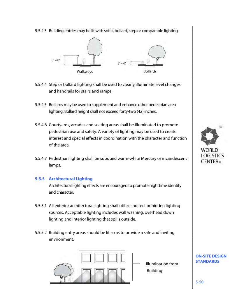
ON-SITE DESIGN STANDARDS 5-50
5.5.4.3 Building entries may be lit with soffit, bollard, step or comparable lighting. 5.5.4.4 Step or bollard lighting shall be used to clearly illuminate level changes
and handrails for stairs and ramps. 5.5.4.5 Bollards may be used to supplement and enhance other pedestrian area
lighting. Bollard height shall not exceed forty-two (42) inches. 5.5.4.6 Courtyards, arcades and seating areas shall be illuminated to promote
pedestrian use and safety. A variety of lighting may be used to create interest and special effects in coordination with the character and function of the area.
5.5.4.7 Pedestrian lighting shall be subdued warm-white Mercury or incandescent lamps.
5.5.5 Architectural Lighting Architectural lighting effects are encouraged to promote nighttime identity and character.
5.5.5.1 All exterior architectural lighting shall utilize indirect or hidden lighting sources. Acceptable lighting includes wall washing, overhead down lighting and interior lighting that spills outside.
5.5.5.2 Building entry areas should be lit so as to provide a safe and inviting
environment.
Illumination from Building
Walkways Bollards
8’ – 0” 3’ – 6”
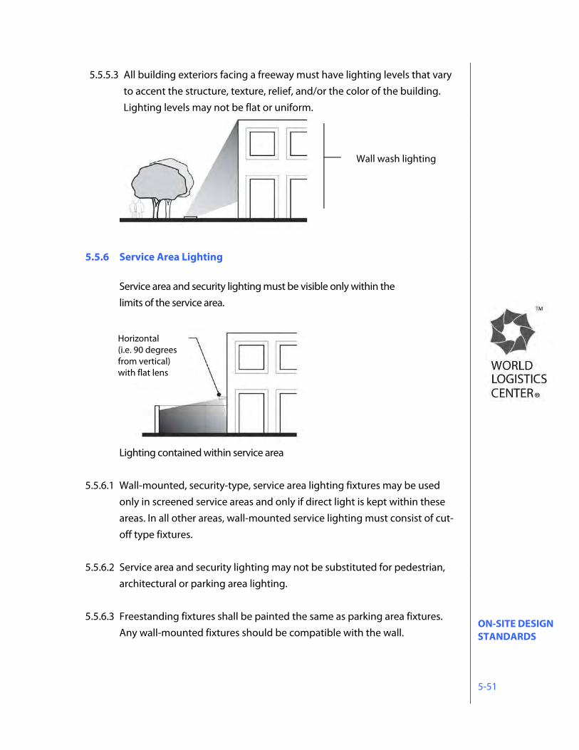
ON-SITE DESIGN STANDARDS 5-51
5.5.5.3 All building exteriors facing a freeway must have lighting levels that vary to accent the structure, texture, relief, and/or the color of the building. Lighting levels may not be flat or uniform.
5.5.6 Service Area Lighting
Service area and security lighting must be visible only within the limits of the service area.
Lighting contained within service area
5.5.6.1 Wall-mounted, security-type, service area lighting fixtures may be used
only in screened service areas and only if direct light is kept within these areas. In all other areas, wall-mounted service lighting must consist of cut-off type fixtures.
5.5.6.2 Service area and security lighting may not be substituted for pedestrian,
architectural or parking area lighting.
5.5.6.3 Freestanding fixtures shall be painted the same as parking area fixtures. Any wall-mounted fixtures should be compatible with the wall.
Wall wash lighting
Horizontal (i.e. 90 degrees from vertical) with flat lens
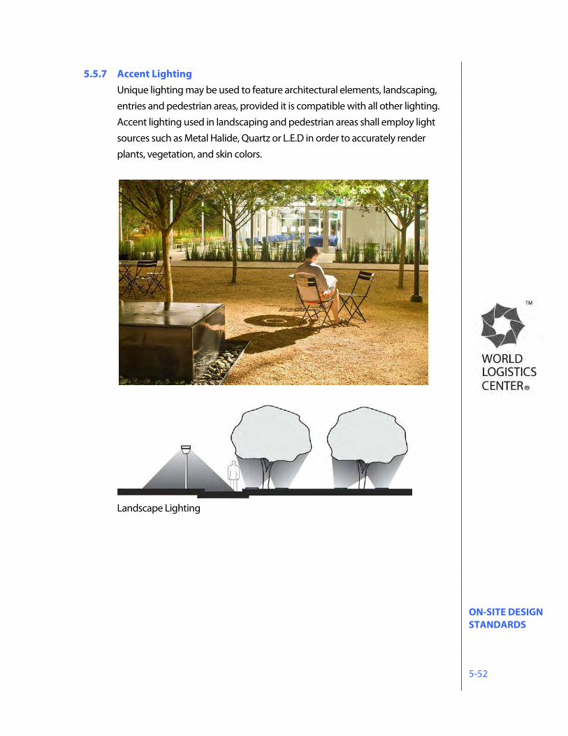
ON-SITE DESIGN STANDARDS 5-52
5.5.7 Accent Lighting Unique lighting may be used to feature architectural elements, landscaping, entries and pedestrian areas, provided it is compatible with all other lighting. Accent lighting used in landscaping and pedestrian areas shall employ light sources such as Metal Halide, Quartz or L.E.D in order to accurately render plants, vegetation, and skin colors.
Landscape Lighting
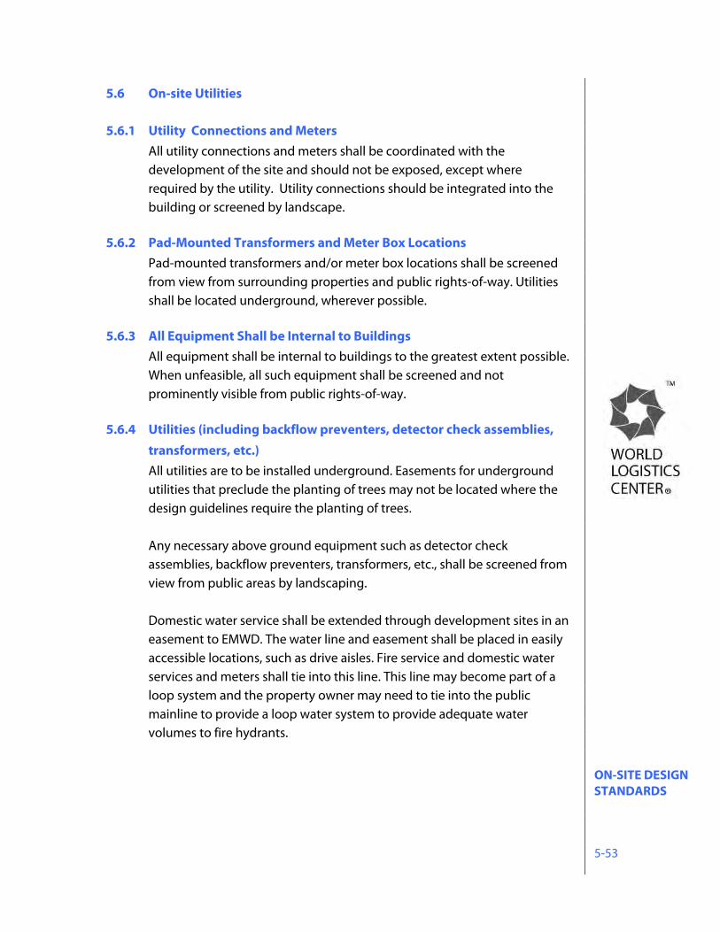
ON-SITE DESIGN STANDARDS 5-53
5.6 On-site Utilities 5.6.1 Utility Connections and Meters
All utility connections and meters shall be coordinated with the development of the site and should not be exposed, except where required by the utility. Utility connections should be integrated into the building or screened by landscape.
5.6.2 Pad-Mounted Transformers and Meter Box Locations
Pad-mounted transformers and/or meter box locations shall be screened from view from surrounding properties and public rights-of-way. Utilities shall be located underground, wherever possible.
5.6.3 All Equipment Shall be Internal to Buildings
All equipment shall be internal to buildings to the greatest extent possible. When unfeasible, all such equipment shall be screened and not prominently visible from public rights-of-way.
5.6.4 Utilities (including backflow preventers, detector check assemblies,
transformers, etc.) All utilities are to be installed underground. Easements for underground utilities that preclude the planting of trees may not be located where the design guidelines require the planting of trees.
Any necessary above ground equipment such as detector check assemblies, backflow preventers, transformers, etc., shall be screened from view from public areas by landscaping. Domestic water service shall be extended through development sites in an easement to EMWD. The water line and easement shall be placed in easily accessible locations, such as drive aisles. Fire service and domestic water services and meters shall tie into this line. This line may become part of a loop system and the property owner may need to tie into the public mainline to provide a loop water system to provide adequate water volumes to fire hydrants.
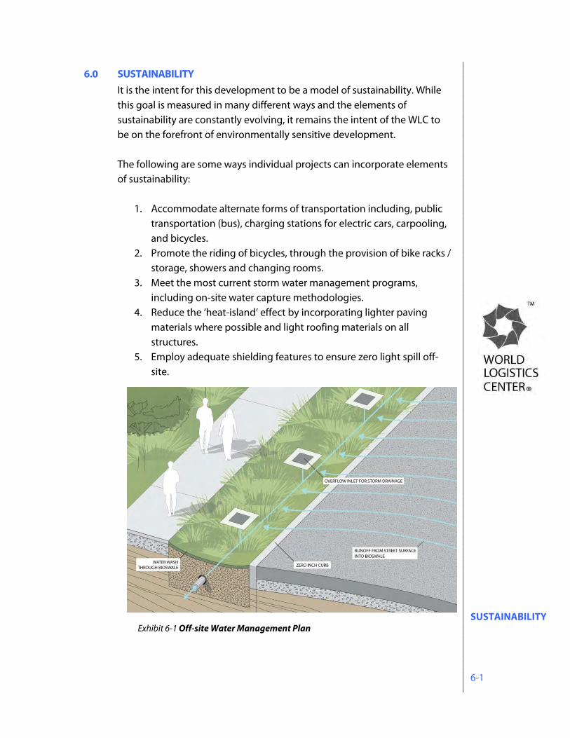
SUSTAINABILITY 6-1
6.0 SUSTAINABILITY It is the intent for this development to be a model of sustainability. While this goal is measured in many different ways and the elements of sustainability are constantly evolving, it remains the intent of the WLC to be on the forefront of environmentally sensitive development.
The following are some ways individual projects can incorporate elements of sustainability:
1. Accommodate alternate forms of transportation including, public
transportation (bus), charging stations for electric cars, carpooling, and bicycles.
2. Promote the riding of bicycles, through the provision of bike racks / storage, showers and changing rooms.
3. Meet the most current storm water management programs, including on-site water capture methodologies.
4. Reduce the ‘heat-island’ effect by incorporating lighter paving materials where possible and light roofing materials on all structures.
5. Employ adequate shielding features to ensure zero light spill off-site.
Exhibit 6-1 Off-site Water Management Plan
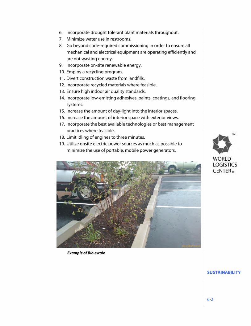
SUSTAINABILITY 6-2
6. Incorporate drought tolerant plant materials throughout. 7. Minimize water use in restrooms. 8. Go beyond code-required commissioning in order to ensure all
mechanical and electrical equipment are operating efficiently and are not wasting energy.
9. Incorporate on-site renewable energy. 10. Employ a recycling program. 11. Divert construction waste from landfills. 12. Incorporate recycled materials where feasible. 13. Ensure high indoor air quality standards. 14. Incorporate low-emitting adhesives, paints, coatings, and flooring
systems. 15. Increase the amount of day-light into the interior spaces. 16. Increase the amount of interior space with exterior views. 17. Incorporate the best available technologies or best management
practices where feasible. 18. Limit idling of engines to three minutes. 19. Utilize onsite electric power sources as much as possible to
minimize the use of portable, mobile power generators.
Example of Bio-swale
SIGNAGE 7-1
7.0 SIGNAGE All signage in this Specific Plan shall conform to an approved Sign Program on file with the City of Moreno Valley.
7.1 Regulatory Signage All regulatory signage (traffic control, public safety, etc.) shall comply with city standards.
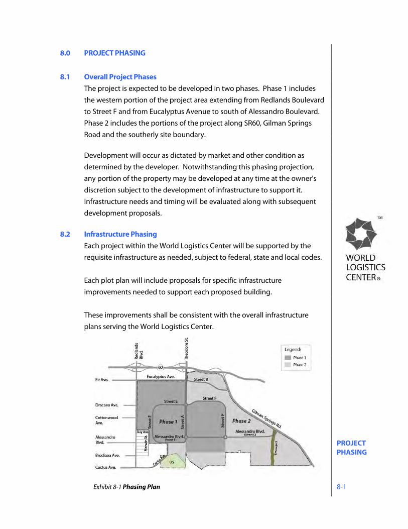
PROJECT PHASING 8-1
8.0 PROJECT PHASING 8.1 Overall Project Phases
The project is expected to be developed in two phases. Phase 1 includes the western portion of the project area extending from Redlands Boulevard to Street F and from Eucalyptus Avenue to south of Alessandro Boulevard. Phase 2 includes the portions of the project along SR60, Gilman Springs Road and the southerly site boundary.
Development will occur as dictated by market and other condition as determined by the developer. Notwithstanding this phasing projection, any portion of the property may be developed at any time at the owner’s discretion subject to the development of infrastructure to support it. Infrastructure needs and timing will be evaluated along with subsequent development proposals.
8.2 Infrastructure Phasing
Each project within the World Logistics Center will be supported by the requisite infrastructure as needed, subject to federal, state and local codes. Each plot plan will include proposals for specific infrastructure improvements needed to support each proposed building. These improvements shall be consistent with the overall infrastructure plans serving the World Logistics Center.
Exhibit 8-1 Phasing Plan

PROPERTY MAINTENANCE 9-1
9.0 PROPERTY MAINTENANCE 9.1 On-site Improvements
On-site improvements shall be maintained by the property owner or tenant, pursuant to private contractual terms.
9.2 Common Area Improvements Major slopes, landscape areas, community entries, community signage, etc., shall be maintained by a property owners’ association.
9.3 Parkways Parkways within public rights-of-way shall be maintained by a property owners’ association or by a maintenance district.
9.4 Streets Public streets (curb-to-curb), public sidewalks, and public trails shall be maintained by the City of Moreno Valley.
FINANCING OF IMPROVEMENTS 10-1
10.0 FINANCING OF IMPROVEMENTS A facilities financing program is important for implementation of the Specific Plan. The financing program needs to assure the timely financing of public streets, utilities, and other necessary capital improvements. Financing for infrastructure improvements encompasses a variety of different mechanisms, processes, and costs that vary based on the type and purpose of an improvement, financial market conditions, debt service considerations, and agency capabilities and policies.
10.1 Capital Financing
Major infrastructure, such as water, sewers, storm drains and roads, may be financed by a special tax established through the formation of a community facilities district (CFD). Another approach may be to create a bond assessment district. Both types of financing districts require tax liens to be placed on participating properties to underwrite the sale of bonds to finance specified improvements. These mechanisms require that the facility to be financed be a public improvement and that participating properties receive a benefit from that improvement. The form of financing selected, if any, will be determined based on the type of uses and pace of development that occurs within the project. Examples include:
1. Community Facility District 2. Other forms of Assessment Districts 3. Facilities Benefit Assessment 4. City/ county direct investment 5. Reimbursement Agreements 6. State and/or federal grants and loans
The developer may elect to use private capital to finance major infrastructure improvements, as well as in-tract improvements to avoid long-term debt assessment upon buyers of improved land.
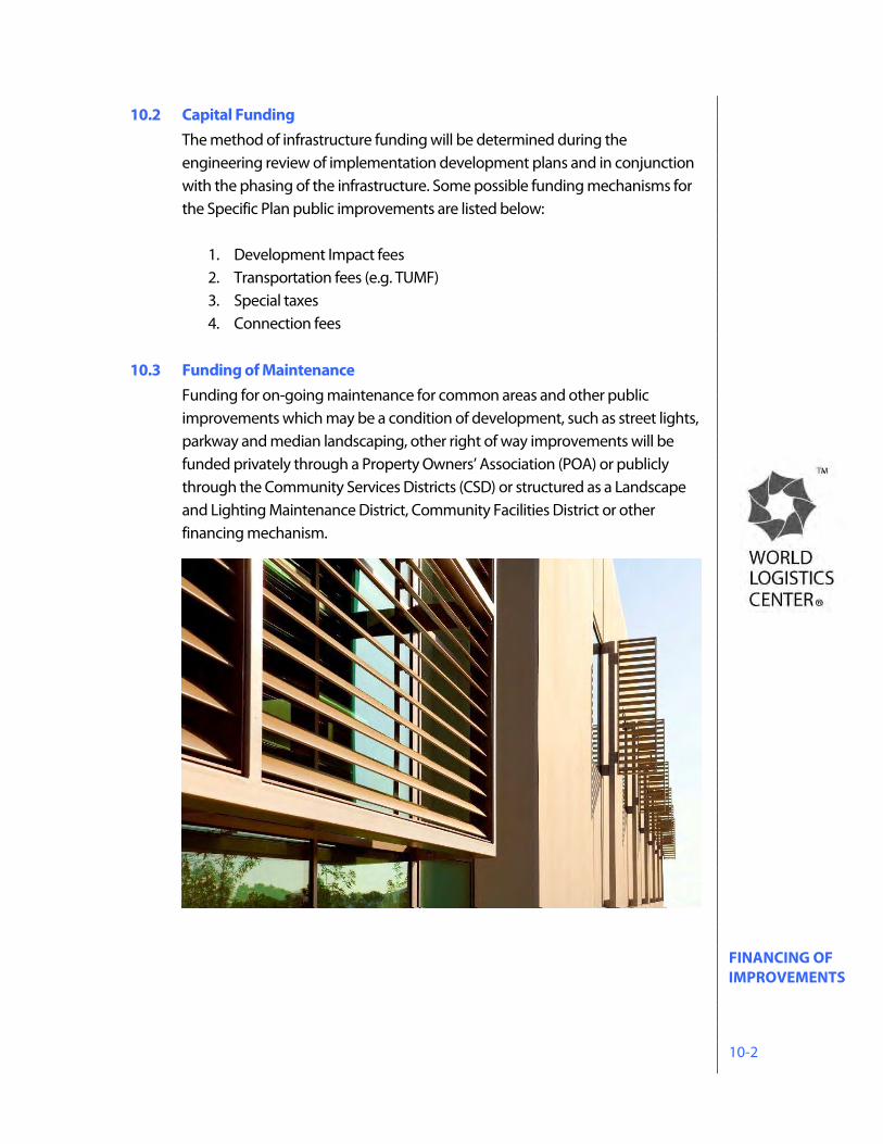
FINANCING OF IMPROVEMENTS 10-2
10.2 Capital Funding The method of infrastructure funding will be determined during the engineering review of implementation development plans and in conjunction with the phasing of the infrastructure. Some possible funding mechanisms for the Specific Plan public improvements are listed below:
1. Development Impact fees 2. Transportation fees (e.g. TUMF) 3. Special taxes 4. Connection fees
10.3 Funding of Maintenance
Funding for on-going maintenance for common areas and other public improvements which may be a condition of development, such as street lights, parkway and median landscaping, other right of way improvements will be funded privately through a Property Owners’ Association (POA) or publicly through the Community Services Districts (CSD) or structured as a Landscape and Lighting Maintenance District, Community Facilities District or other financing mechanism.
IMPLEMENTATION 11-1
11.0 IMPLEMENTATION
11.1 Purpose and Intent This section contains the procedures for the processing of discretionary development applications to implement the terms of the World Logistics Center Specific Plan. The City will review all development within the project to ensure compliance with the provisions of the Specific Plan.
11.2 Approvals Required All development within the World Logistics Center is subject to the approval of a Plot Plan in conformance with these procedures. Modifications to the development standards contained in the Specific Plan may be requested by any property owner and may be approved by the City through the variance processes described in Section 11.3.3 herein.
11.3 Development Review Process
11.3.1 Subdivisions All proposed subdivisions within the World Logistics Center shall be processed in accordance with the provisions of the state Subdivision Map Act and the Municipal Code.
11.3.2 Plot Plans
a. All development proposals within the World Logistics Center shall be subject to the approval of a Plot Plan as described herein. Property and building maintenance activities such as painting, site or building repairs,
IMPLEMENTATION 11-2
parking lot resurfacing/restriping, and landscape maintenance and repair, etc. are exempt from these regulations. b. The Plot Plan process is intended to ensure that all development proposals comply with all applicable standards and guidelines contained in this Specific Plan and are not detrimental to public health, safety or welfare. c. Plot Plan applications shall be submitted to the City in conformance with the procedures contained in the Municipal Code . d. The Community Development Director may approve, conditionally approve, or disapprove a Plot Plan application as provided for in the Municipal Code or may elevate the application to the Planning Commission for review and action. Considerations for Planning Commission review of a plot plan application may include but are not limited to:
1. The need for preparation of a Supplemental Environmental Impact Report or other appropriate environmental document due to new circumstances that become present and constitute potential for significant impacts which were unknown and could not have been known at the time of the approval of this Specific Plan 2. If any buildings greater than 500,000 square feet cannot meet LEED Certified Building Standards and/or buildings are not consistent with Specific Plan energy efficiency standards 3. Building elevations not consistent with the Specific Plan design guidelines 4. Future modification to any state or federal regulations requiring review of such Specific Plan permitted development
e. Project comments received from the Architectural Review Committee of the World Logistics Center Property Owners’ Association shall receive consideration in the review process. f. Public noticing shall be in compliance with the Municipal Code g. A Plot Plan may be approved if all of the following findings are made:
IMPLEMENTATION 11-3
1. The proposed project is consistent with the goals, objectives and policies of the General Plan, 2. The proposed project complies with this Specific Plan and other applicable regulations, and 3. The proposed project will not be detrimental to the public health, safety or welfare or materially injurious to properties or improvements in the vicinity,
h. Reasonable conditions of approval may be imposed to ensure compliance with applicable laws, regulations and standards or to enable the required findings to be made.
11.3.3 Variances Alternatives to development standards and regulations contained herein may be approved through the following variance procedures. Variance applications may be processed along with Plot Plan applications, or as separate applications.
11.3.3.1 Administrative Variances a. The purpose of an administrative variance is to provide an
administrative procedure for adjustments to certain regulations in this Specific Plan in order to prevent hardships that might result from a strict or literal interpretation and enforcement of those regulations.
b. The standards and procedures for the submittal, review and approval
of an Administrative Variance shall be as contained in Section 9.02.090 of the Municipal Code.
11.3.3.2 Other Variances
a. All other variance applications shall be processed in accordance with Section 9.02.100 of the Municipal Code
11.3.4 Appeals
a. Any interested party may appeal any administrative decision to the Planning Commission subject to the provisions of Section 9.02.240 of the Municipal Code.
b. Any interested party may appeal any decision of the Planning Commission to the City Council subject to the provisions of Section 9.02.240 of the Municipal Code.
c. The decision of the City Council is final.
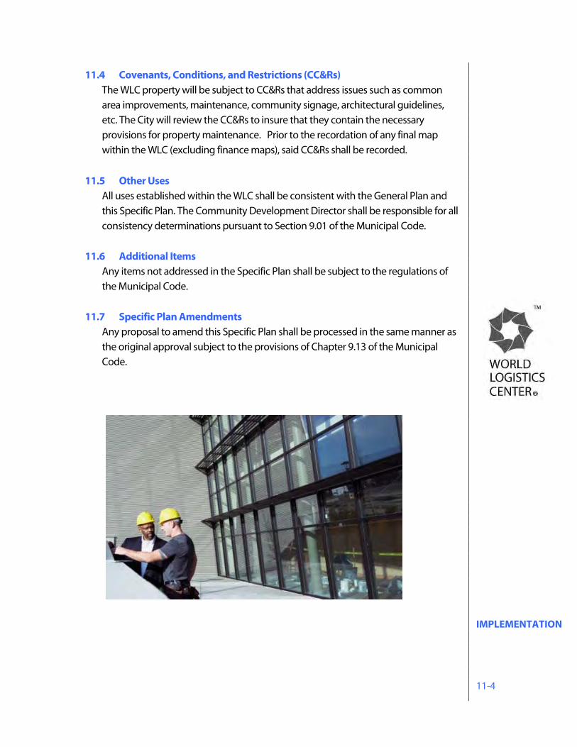
IMPLEMENTATION 11-4
11.4 Covenants, Conditions, and Restrictions (CC&Rs) The WLC property will be subject to CC&Rs that address issues such as common area improvements, maintenance, community signage, architectural guidelines, etc. The City will review the CC&Rs to insure that they contain the necessary provisions for property maintenance. Prior to the recordation of any final map within the WLC (excluding finance maps), said CC&Rs shall be recorded.
11.5 Other Uses
All uses established within the WLC shall be consistent with the General Plan and this Specific Plan. The Community Development Director shall be responsible for all consistency determinations pursuant to Section 9.01 of the Municipal Code.
11.6 Additional Items Any items not addressed in the Specific Plan shall be subject to the regulations of the Municipal Code.
11.7 Specific Plan Amendments Any proposal to amend this Specific Plan shall be processed in the same manner as the original approval subject to the provisions of Chapter 9.13 of the Municipal Code.
SPECIAL REGULATIONS 12-1
12.0 SPECIAL REGULATIONS The following regulations apply to all development within the World Logistics Center. These restrictions shall be imposed on all discretionary permits for new development projects, as applicable.
12.1 Secure Trucking Areas All truck areas shall be secured with manned gates during building operation.
12.2 Engine Restrictions
All trucks with a gross vehicle weight of 15,000 pounds or more entering any warehouse facility must meet or exceed 2010 engine emission standards specified in California Code of Regulations Title 13, Article 4.5, Chapter 1, Section 2025 or be powered by natural gas, electricity, or other non-diesel fuel source. Facility operators shall maintain a log of all trucks entering a warehouse site to document that this requirement is met. This log shall be available for inspection by the City at any time.
12.3 On-site Service Vehicles
The use of diesel-powered service yard vehicles (yard goats, etc.) is prohibited at all times within the Specific Plan area. Pallet jacks, forklifts, and other onsite equipment used during building operation (indoors or outdoors) shall be powered by electricity, natural gas, propane, or other non-diesel fuel.
12.4 Property Maintenance Equipment Electrical power sources will be provided both indoors and outdoors to accommodate the use of electric property maintenance equipment.
12.5 Continued Agricultural Activities (Right-to-Farm)
As the World Logistics Center develops, logistics land uses will begin to locate in proximity to existing agricultural activities. Where non-agricultural uses locate near agricultural uses, there is the potential for conflict. These potential conflicts result from the inherent attributes of agricultural operations, including noise, odor, dust, smoke, operation of machinery (including aircraft), crop dusting, storage and disposal of manure, flies, rodents, chemical fertilizers, soil amendments, herbicides, pesticides and the hours of operation. As a result, such agricultural operations can become the subject of nuisance complaints and could be pressured to cease or curtail operations or may be discouraged from making farm improvements.
SPECIAL REGULATIONS 12-2
To protect the continued viability of agricultural operations within the World Logistics Center, it is the intent of this Specific Plan to limit the circumstances under which pre-existing agricultural operations may be deemed to constitute a nuisance. The intent of this policy of the Specific Plan is to balance the rights of farmers to produce agricultural commodities with the rights of non-farmers who own, occupy or use land adjacent to agricultural property. This right-to-farm policy applies to all legally established agricultural operations existing at the time of the effective date of the World Logistics Center Specific Plan.
12.6 Air Quality and Noise Assessment To address the relationship between development areas and adjacent residential areas, all site development permit applications for properties adjacent to residentially occupied or zoned properties shall include detailed air quality and noise assessments to determine appropriate project design features to meet the performance requirements of the WLC project Environmental Impact Report.
12.7 Solar Commitment All logistics buildings within the LD and LL categories shall provide rooftop solar energy systems sized to offset the power demands of office space contained in the building.
12.8 LEED Standards
All buildings in the World Logistics Center, of at least 500,000 square feet, shall be designed to meet or exceed LEED Certified status in accordance with LEED standards and criteria in effect as of the date of approval of this Specific Plan. Such standards and criteria are contained in the following documents:
- LEED Reference Guide for Green Building Design and Construction – LEED 2009
- Green Building and LEED Core Concepts Guide – Second Edition - LEED for New Construction 2009 Reference Guide – LEED v2.2, Third
edition - LEED for Core and Shell 2009 Reference Guide - LEED Reference Guide for Green Interior Design and Construction –
LEED 2009 - LEED for Commercial Interiors 2009 Reference Guide - Advanced Energy Modeling for LEED: Technical Manual v1.0
SPECIAL REGULATIONS 12-3
- LEED Reference Guide for Green Building Operations and Maintenance – LEED 2009
12.9 Alessandro Boulevard – Historical Landmark
A portion of the alignment of historic Alessandro Boulevard, as established by Resolution CPAB 88-2, runs through the WLC area. The Specific Plan recognizes the landmark status of this roadway and provides for the preservation of its entire 120-foot right-of-way through the project. Most of this historic right-of-way is included within Alessandro Boulevard as shown on the Specific Plan exhibits. As the WLC is developed, Alessandro Boulevard will be built to modern roadway standards within the historic alignment. In order to meet these standards, very minor portions of this roadway MAY fall outside of the historic right-of-way. In those instances, the historic right-of-way will be retained and may be improved with walks, trails, landscaping or similar compatible improvements. In the southwestern portion of the WLC, vehicular traffic will be prohibited on a short reach of historic Alessandro Boulevard. The purpose of this restriction is to reduce through traffic and associated impacts on the existing residential portion of Alessandro Boulevard. This right-of-way will be retained and will be available for use for a future multi-use trail, pedestrian access, emergency access, and monuments, signs or other displays recognizing Moreno Valley’s rich history. Prior to approval of any development including or adjacent to the historic Alessandro Boulevard right-of-way, a concept plan for its entire length shall be submitted to and approved by the Planning Commission.
DEFINITIONS 13-1
13.0 DEFINITIONS 12kV/115 kV overhead power lines Power lines that distribute electrical power into and through the World Logistics Center project. While 12kV lines are generally placed underground, 115kV lines must remain aboveground due to the heat generated by the flow of electrical energy in the lines. Accessory Structure A separate building, the use of which is incidental to that of the main building on the same lot or premises, and which is used exclusively by the occupant of the main building. Ancillary Structures See accessory structure Arterial Streets A highway intended to serve through traffic where access rights are restricted and intersections with other streets or highways are limited Badlands A rugged, mountainous area located easterly of the City of Moreno Valley, east of Gilman Springs Road in Riverside County. Bioretention Facilities Soil and plant-based filtration devices that remove pollutants through a variety of physical, biological, and chemical treatment processes. These facilities normally consist of a grass buffer strip, sand bed, ponding area, organic layer or mulch layer, planting soil, and plants. Building height The vertical distance from the adjacent grade to the highest point of a building exclusive of vents, air conditioners, or other such incidental appurtenances. Class II bikeways A striped lane located along the right shoulder of a roadway designated for use by bicyclists. CNG/LNG Abbreviation for Compressed Natural Gas (CNG) and Liquefied Natural Gas (LNG). Collector Roads A street intended to convey traffic into and through an area from local roads to arterial streets Cut-off fixtures A lighting fixture designed to eliminate light rays from escaping above a horizontal plane. Detention basins A drainage feature that has been designed to allow large flows of water to enter but limits the outflow by having a small opening at the lowest point of the outlet structure. Drainage 9 Refers to an existing ephemeral drainage located in the eastern area of the Specific Plan from Gilman Springs Road flowing south to the SJWA as shown on Exhibit 1-2. This watercourse is referred to as Line E in the drainage studies
DEFINITIONS 13-2
contained in the DEIR. Line E collects water under Gilman Springs Road at Culvert 5. Eastern Municipal Water District (EMWD) The water district which provides potable water, recycled water and wastewater treatment for the World Logistics Center project. Facades An exterior side of a building, usually, but not always, the front. Fenestration The design of openings in a building or wall, generally including windows, doors, louvers, vents, openings, skylights, storefronts, etc. Floor area ratio A measure of the intensity of development of a particular site. The ratio is calculated by dividing the building area by the parcel area, using the same unit of measure (acres, square feet, etc.) Heavy truck A truck having four axles or more. High-cube warehouse A building used for the storage and/or consolidation of manufactured goods prior to distribution to secondary retail outlets, generally 500,000 square feet or more, often divided for multiple tenants. High-cube warehouse and logistics facilities include ancillary office and maintenance space along with the outdoor storage of trucks, trailers, and shipping containers. High-cube logistics warehouses are generally constructed with vertical-lift dock-high roll up doors to allow access for the loading and unloading of products from truck/trailers. Building interiors are typically large and open to accommodate the temporary storage and consolidation of the products to be distributed. Highland Fairview Corporate Park A mixed use business park made up of logistics and commercial land uses located between Redlands Blvd and Theodore Street, southerly of SR60. Impervious paved surface Artificial surfaces such as pavement (roads, sidewalks, driveways and parking lots) that are covered by impenetrable materials such as asphalt, concrete, brick, and stone. Also includes building rooftops and other structures that prevent water from penetrating into the ground surface. Infiltration Basin A shallow impoundment that is designed to infiltrate stormwater. Infiltration basins use the natural filtering ability of the soil to remove pollutants in stormwater runoff. Jobs/housing balance The ratio between the number of housing units and the number of full-time jobs in an identified geographic area. The ratio is calculated by dividing the number of full-time jobs by the number of housing units.
DEFINITIONS 13-3
Lake Perris State Recreation Area A 6,675-acre state-owned recreation area including Lake Perris located southerly of the City of Moreno Valley. Logistics The management of the flow of resources between a point of origin and a point of destination including the importation, warehousing, consolidation, repackaging and shipping of goods and materials. Luminaire A light fixture generally affixed to a pole used in exterior areas to illuminate streets, driveways, walkways, and parking areas. Medium trucks Trucks having three axles Multi-Use Trails A planned city-wide system of trails that accommodate pedestrian, equestrian and bicycle users. See the Parks, Recreation and Open Space Element of the City’s General Plan Native landscape The use of plant materials found to grow naturally in an area that are adapted to a particular environment and are able to live on natural rainfall, thereby reducing the need for mechanical irrigation Off-project Refers to areas outside of the World Logistics Center. Generally applies to infrastructure improvements needed to implement the WLC project that will extend beyond the WLC boundary. Off-site Refers to those portions of the property that are not within building sites, including common areas, open space, public areas, streetscapes, etc. On-site Refers to individual building sites within the World Logistics Center San Jacinto Wildlife Area (SJWA) A 9,000–acre area owned and managed by the California Department of Fish and Wildlife open to the public. Approximately 1,100 acres of the northerly portion of the SJWA is within the City of Moreno Valley. Specific Plan Refers to the World Logistics Center Specific Plan which covers 2,610 acres of land in eastern Moreno Valley and functions as the land use regulations for the development of a master planned logistics campus. Subdivision Map Act The body of law (Government Code Section 66410-66499.58) that regulates the subdivision of land in California. Truck Routes/Truck Route Ordinance Streets that have been officially designated by for use by vehicles with a gross vehicle weight of three tons or more. See Chapter 12.36 of the Municipal Code. World Logistics Center The project name for the development to be established under the World Logistics Center Specific Plan
EXHIBITS E-1
EXHIBITS Enlargements of Exhibits contained within the Specific Plan
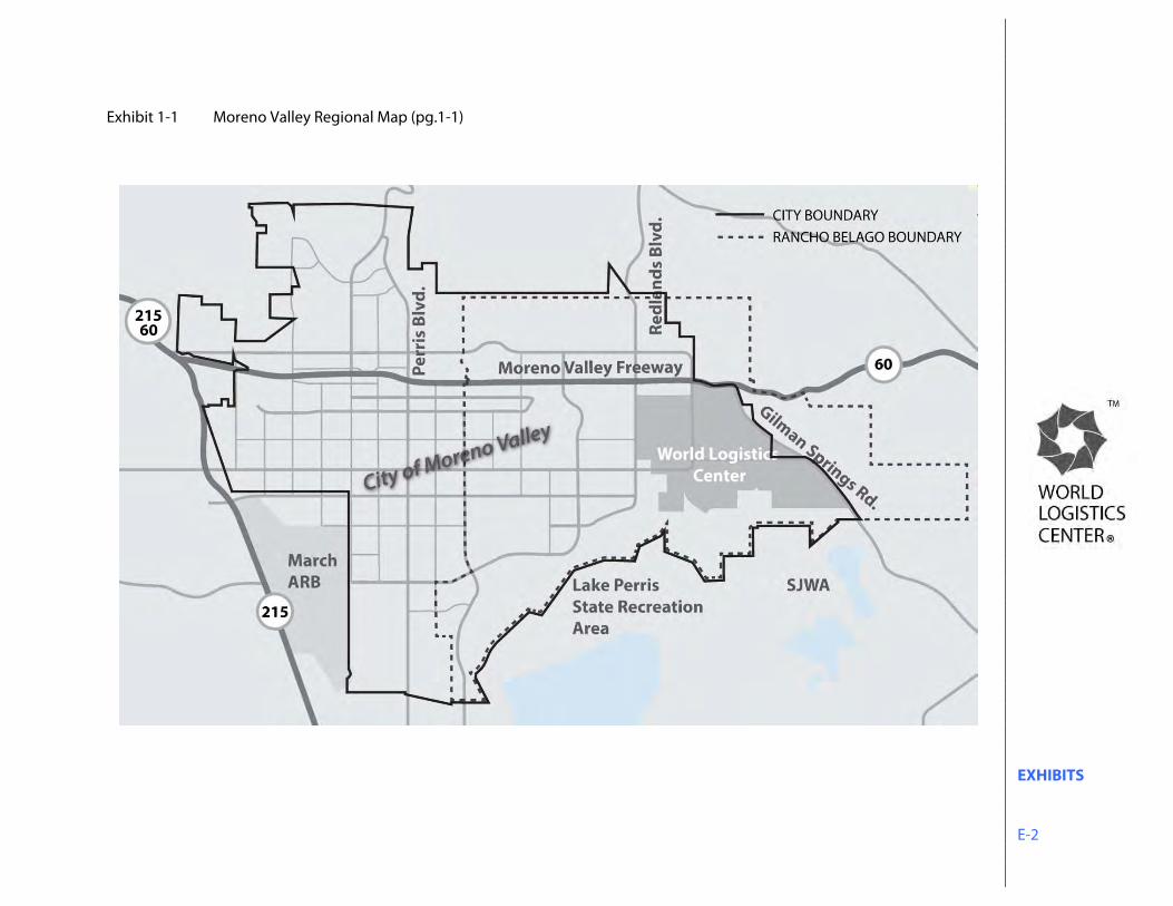
EXHIBITS E-2
Exhibit 1-1 Moreno Valley Regional Map (pg.1-1)
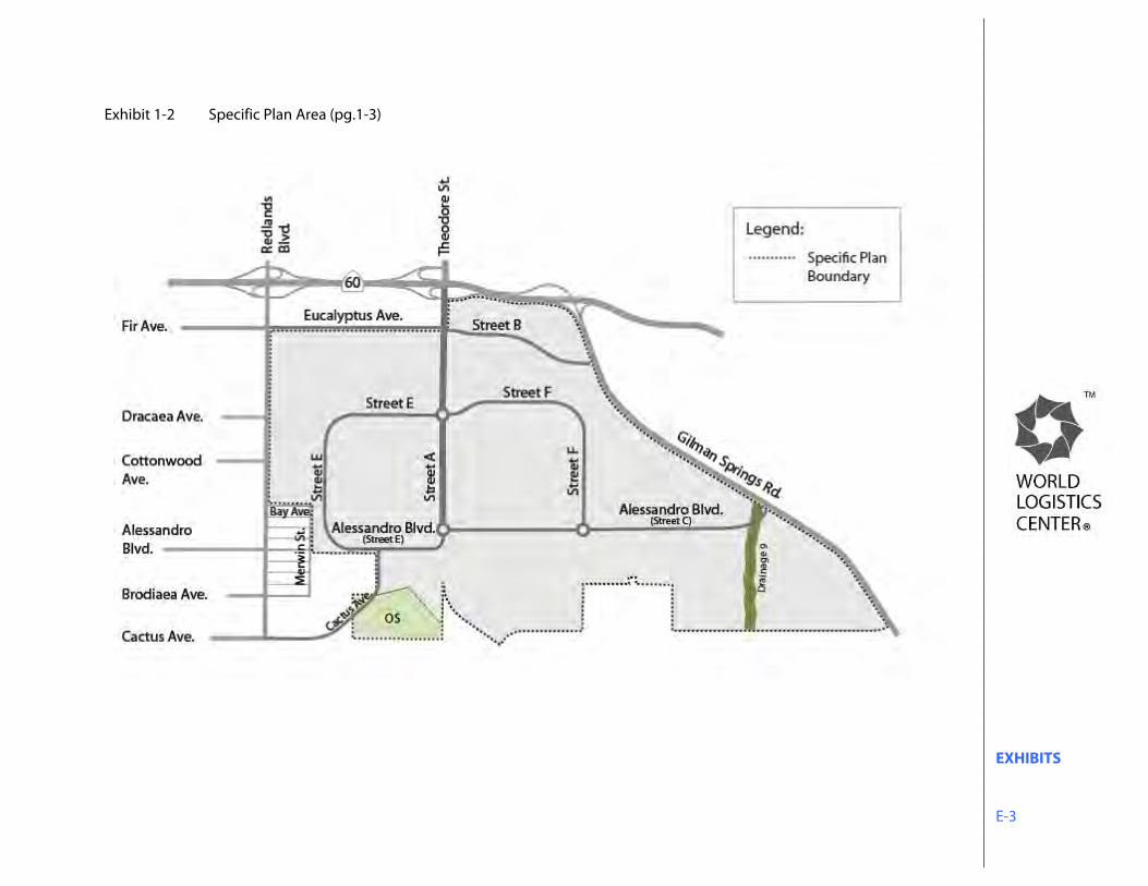
EXHIBITS E-3
Exhibit 1-2 Specific Plan Area (pg.1-3)
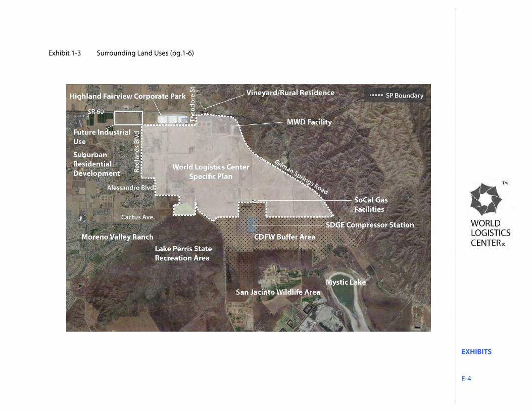
EXHIBITS E-4
Exhibit 1-3 Surrounding Land Uses (pg.1-6)
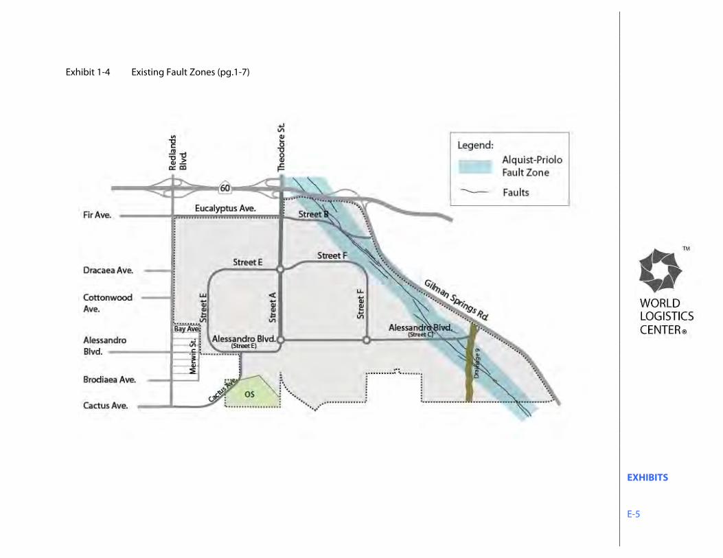
EXHIBITS E-5
Exhibit 1-4 Existing Fault Zones (pg.1-7)
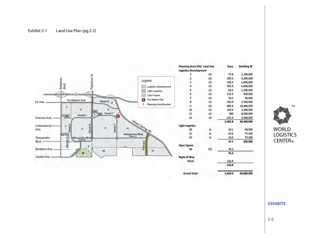
EXHIBITS E-6
Exhibit 2-1 Land Use Plan (pg.2-2)
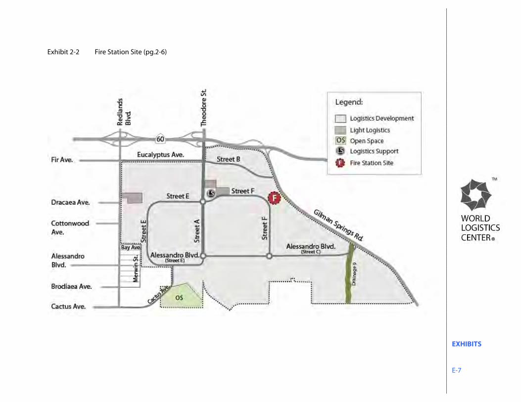
EXHIBITS E-7
Exhibit 2-2 Fire Station Site (pg.2-6)
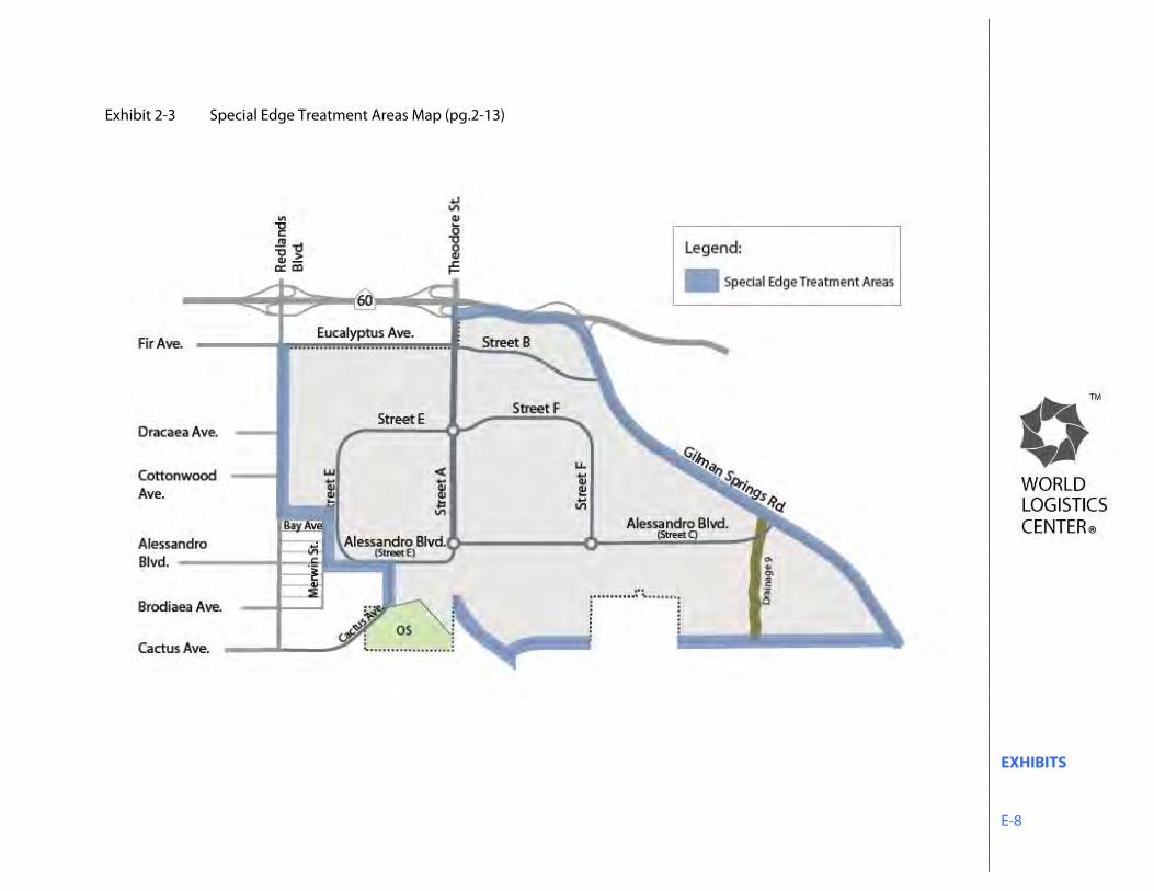
EXHIBITS E-8
Exhibit 2-3 Special Edge Treatment Areas Map (pg.2-13)
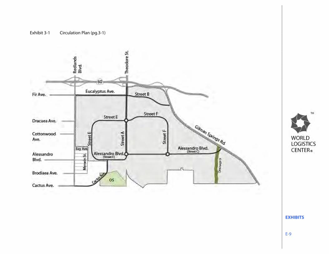
EXHIBITS E-9
Exhibit 3-1 Circulation Plan (pg.3-1)
EXHIBITS E-10
Exhibit 3-2 Project Entries (pg.3-2)
EXHIBITS E-11
Exhibit 3-3 Street Configurations (pg.3-3)
EXHIBITS E-12
Exhibit 3-4a Street “A” (Theodore Street) North of Street “E” (pg.3-4)
Exhibit 3-4b Street “A” (Theodore Street) South of Street “E” (pg.3-4)
Street “A” (Theodore Street) North of Street “E”
Street “A” (Theodore Street) South of Street “E”
EXHIBITS E-13
Exhibit 3-5 Eucalyptus Avenue (pg.3-5) Exhibit 3-6 Street “B” (Eucalyptus Avenue Extension) (pg.3-5)
Street “B” (Eucalyptus Avenue Extension)
Eucalyptus Avenue
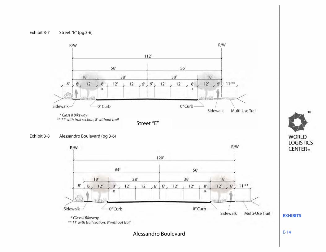
EXHIBITS E-14
Exhibit 3-7 Street “E” (pg.3-6) Exhibit 3-8 Alessandro Boulevard (pg 3-6)
Street “E”
Alessandro Boulevard
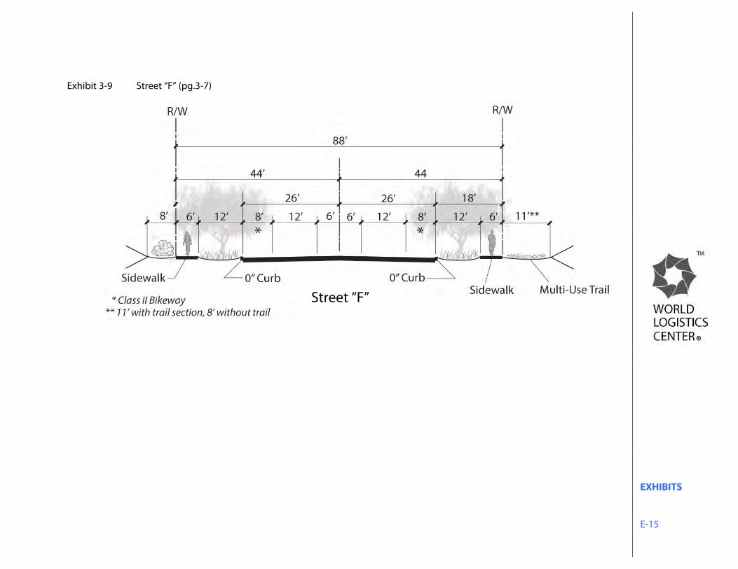
EXHIBITS E-15
Exhibit 3-9 Street “F” (pg.3-7)
Street “F”
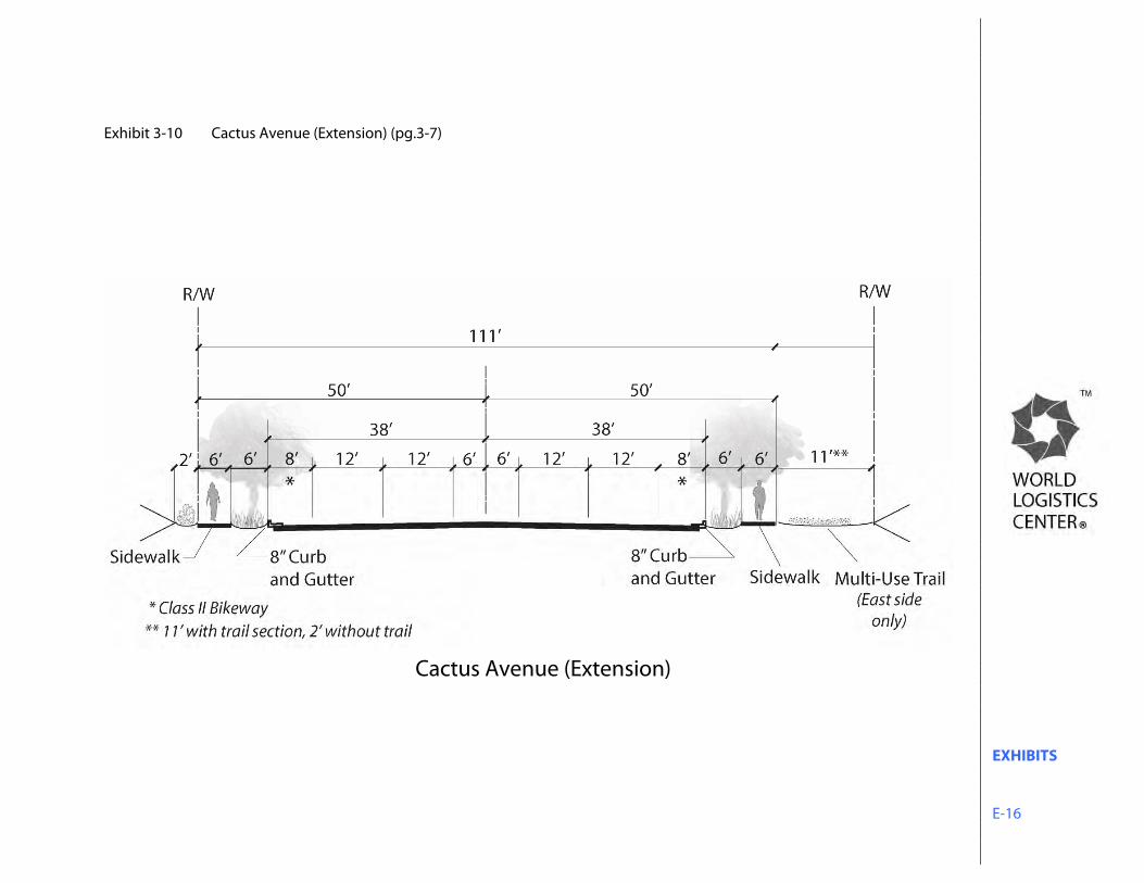
EXHIBITS E-16
Exhibit 3-10 Cactus Avenue (Extension) (pg.3-7)
Cactus Avenue (Extension)
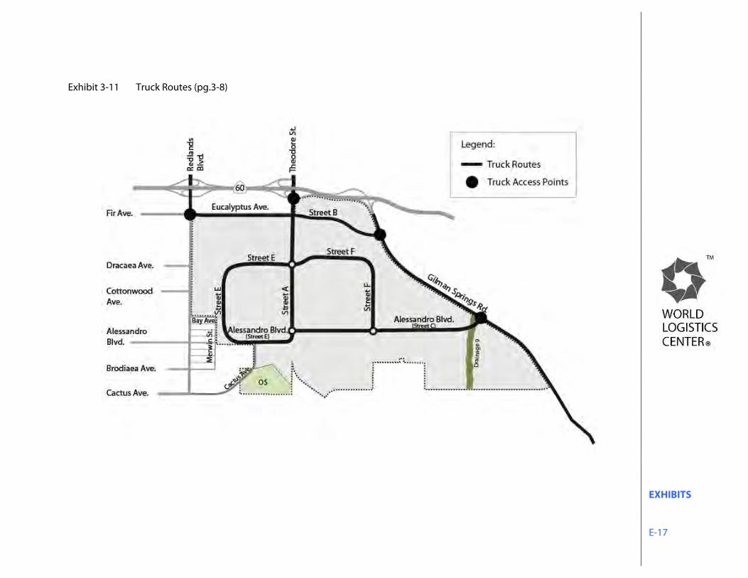
EXHIBITS E-17
Exhibit 3-11 Truck Routes (pg.3-8)
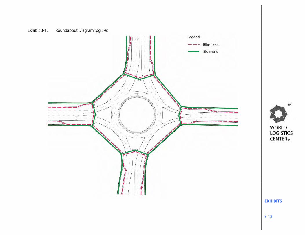
EXHIBITS E-18
Exhibit 3-12 Roundabout Diagram (pg.3-9)

EXHIBITS E-19
Exhibit 3-13 Truck Pullout Diagram (pg.3-10)
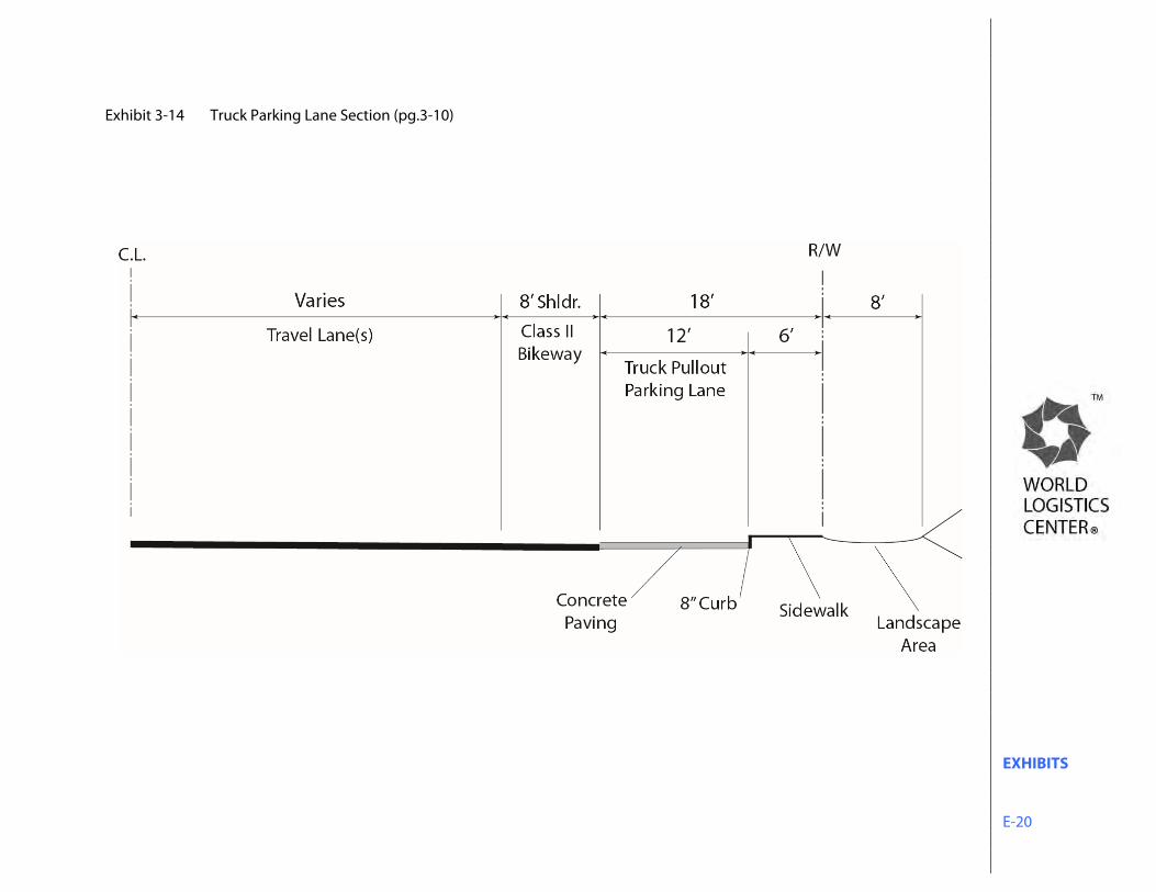
EXHIBITS E-20
Exhibit 3-14 Truck Parking Lane Section (pg.3-10)
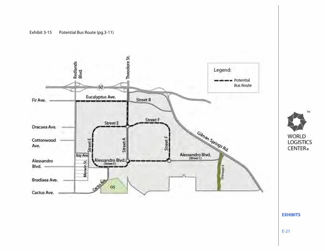
EXHIBITS E-21
Exhibit 3-15 Potential Bus Route (pg.3-11)
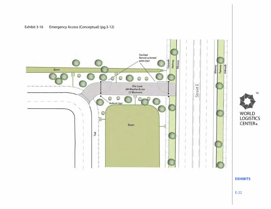
EXHIBITS E-22
Exhibit 3-16 Emergency Access (Conceptual) (pg.3-12)
EXHIBITS E-23
Exhibit 3-17 Multi-Use Trail Plan (pg.3-13)
EXHIBITS E-24
Exhibit 3-18 Bicycle Circulation Plan (pg.3-14)
EXHIBITS E-25
Exhibit 3-19 Water Facilities Master Plan (pg.3-15)
EXHIBITS E-26
Exhibit 3-20 Wastewater Service Plan (pg.3-17)
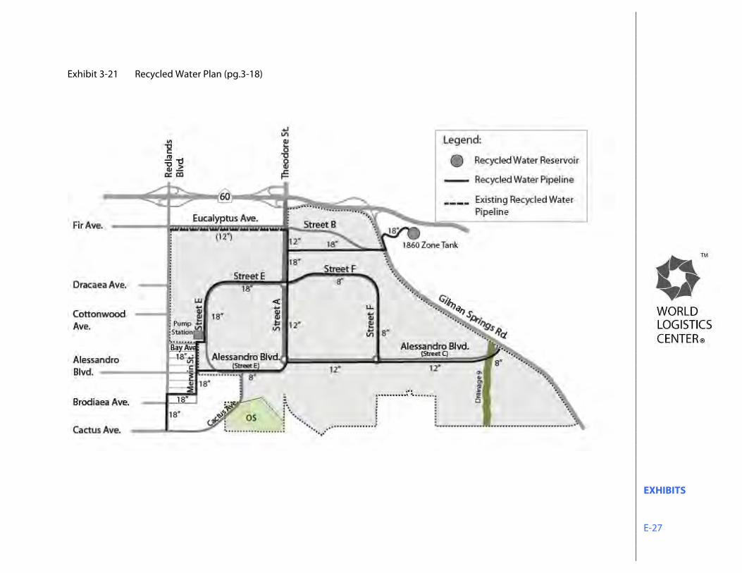
EXHIBITS E-27
Exhibit 3-21 Recycled Water Plan (pg.3-18)
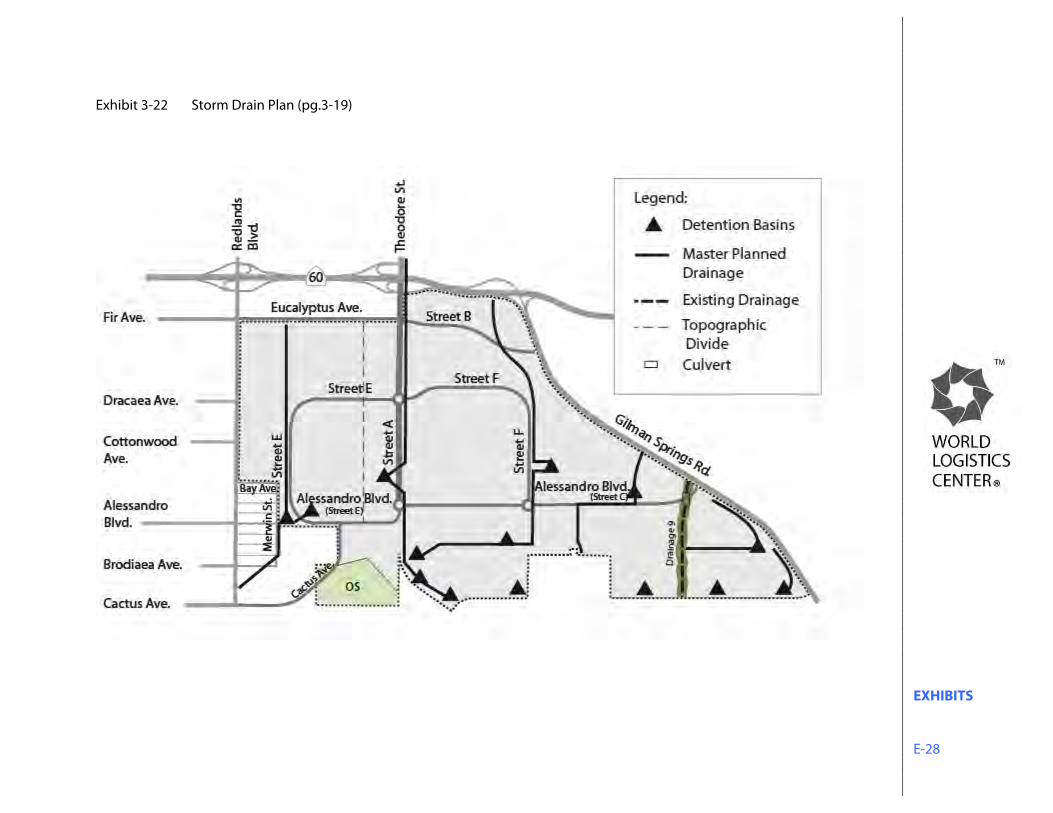
EXHIBITS E-28
Exhibit 3-22 Storm Drain Plan (pg.3-19)
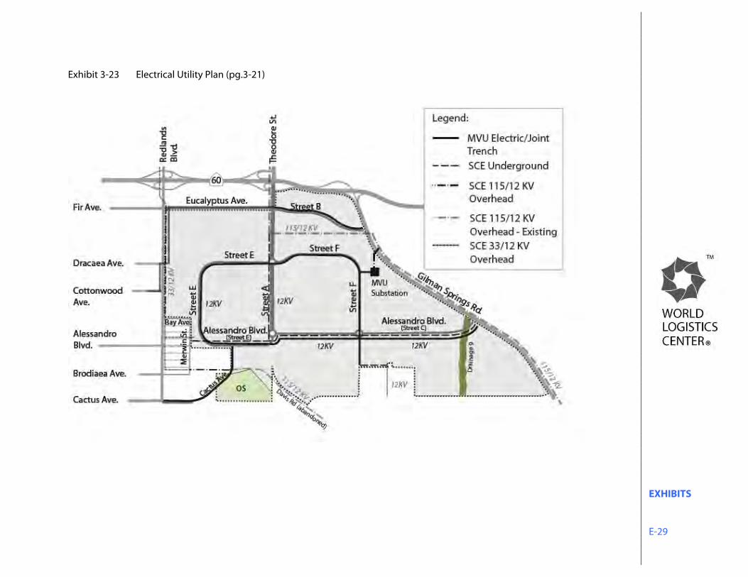
EXHIBITS E-29
Exhibit 3-23 Electrical Utility Plan (pg.3-21)
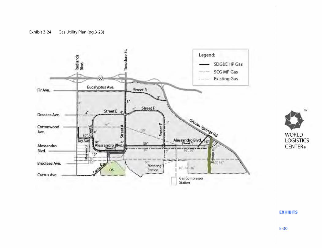
EXHIBITS E-30
Exhibit 3-24 Gas Utility Plan (pg.3-23)
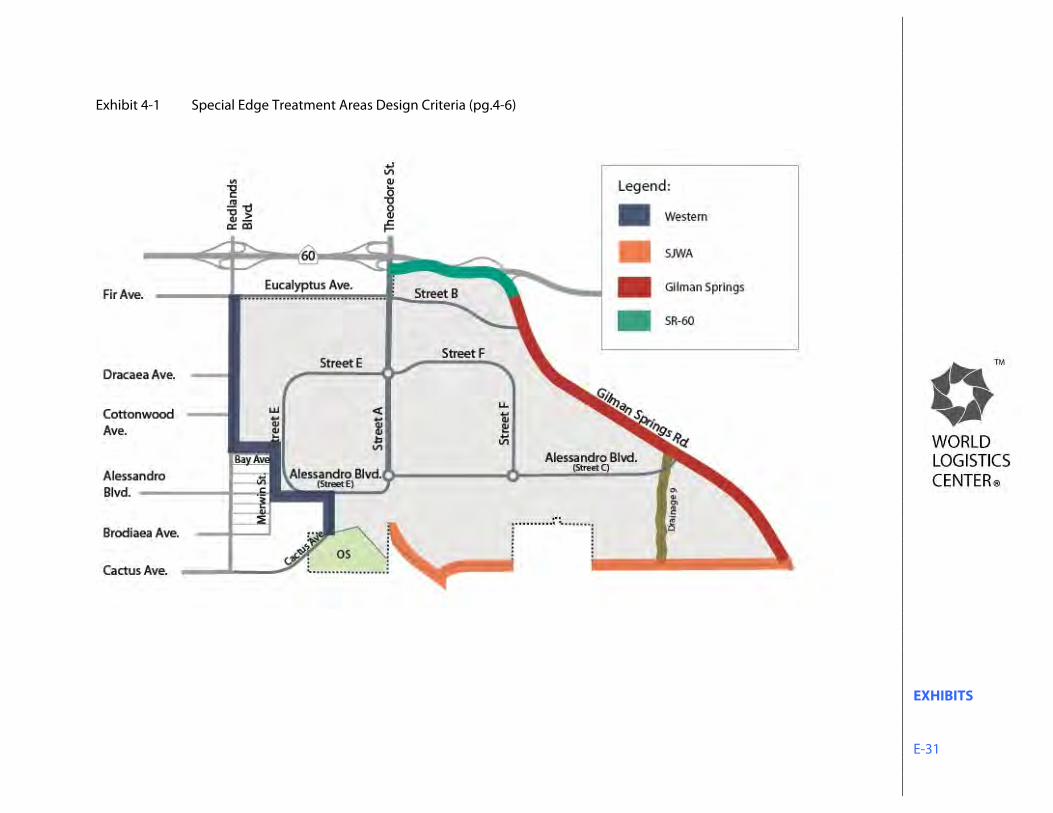
EXHIBITS E-31
Exhibit 4-1 Special Edge Treatment Areas Design Criteria (pg.4-6)
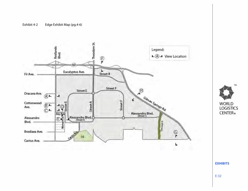
EXHIBITS E-32
Exhibit 4-2 Edge Exhibit Map (pg.4-6)
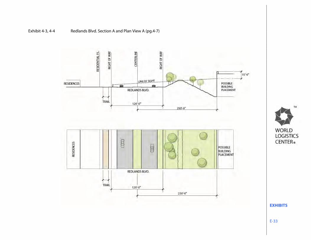
EXHIBITS E-33
Exhibit 4-3, 4-4 Redlands Blvd. Section A and Plan View A (pg.4-7)
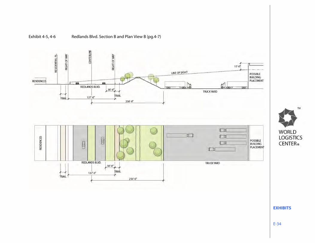
EXHIBITS E-34
Exhibit 4-5, 4-6 Redlands Blvd. Section B and Plan View B (pg.4-7)
EXHIBITS E-35
Exhibit 4-7, 4-8 Redlands Blvd. Section C and Plan View C (pg.4-8)
EXHIBITS E-36
Exhibit 4-9, 4-10 Bay Avenue Section D and Plan View D (pg.4-8)
EXHIBITS E-37
Exhibit 4-11, 4-12 Merwin Street Section E and Plan View E (pg.4-9)
EXHIBITS E-38
Exhibit 4-13 SR-60 between Theodore and Gilman Springs Rd. Section F (pg.4-9)
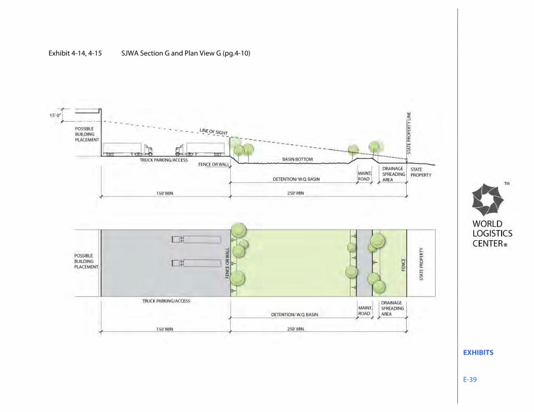
EXHIBITS E-39
Exhibit 4-14, 4-15 SJWA Section G and Plan View G (pg.4-10)
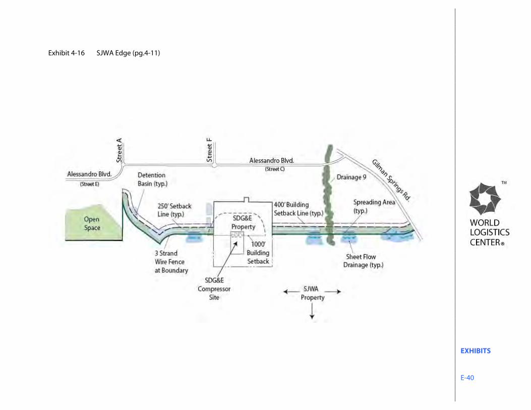
EXHIBITS E-40
Exhibit 4-16 SJWA Edge (pg.4-11)
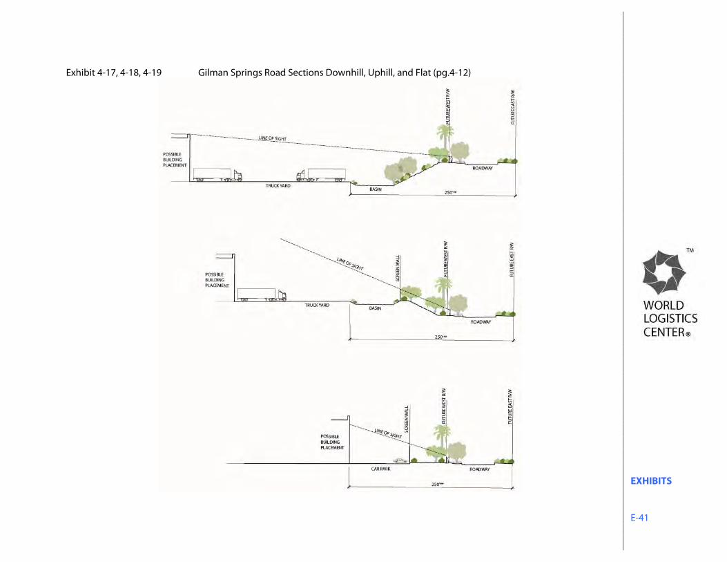
EXHIBITS E-41
Exhibit 4-17, 4-18, 4-19 Gilman Springs Road Sections Downhill, Uphill, and Flat (pg.4-12)
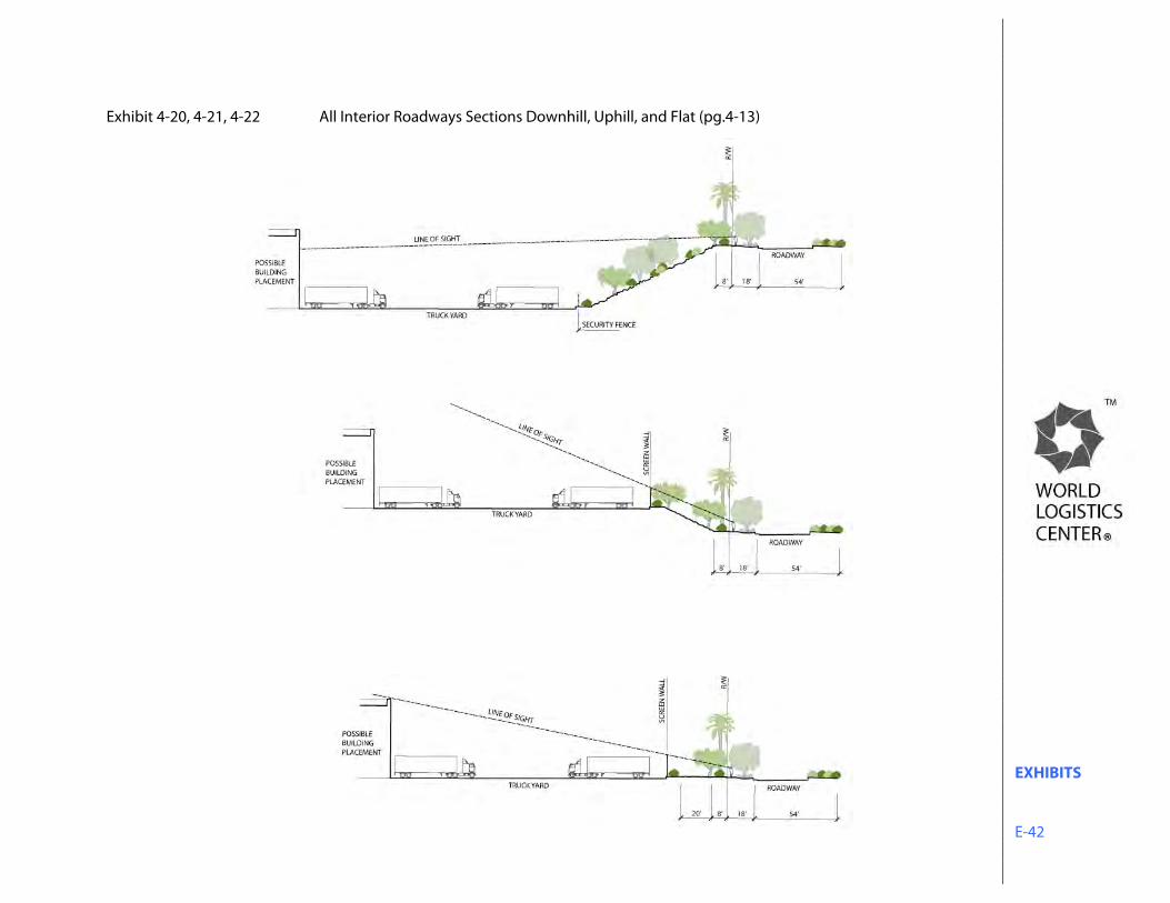
EXHIBITS E-42
Exhibit 4-20, 4-21, 4-22 All Interior Roadways Sections Downhill, Uphill, and Flat (pg.4-13)
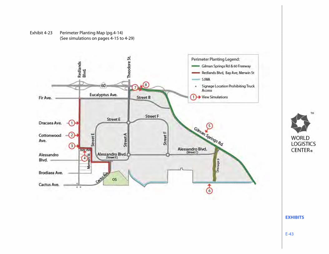
EXHIBITS E-43
Exhibit 4-23 Perimeter Planting Map (pg.4-14) (See simulations on pages 4-15 to 4-29)
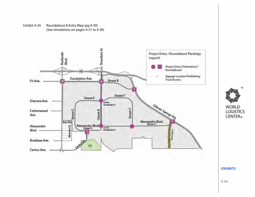
EXHIBITS E-44
Exhibit 4-24 Roundabout & Entry Map (pg.4-30) (See simulations on pages 4-31 to 4-36)
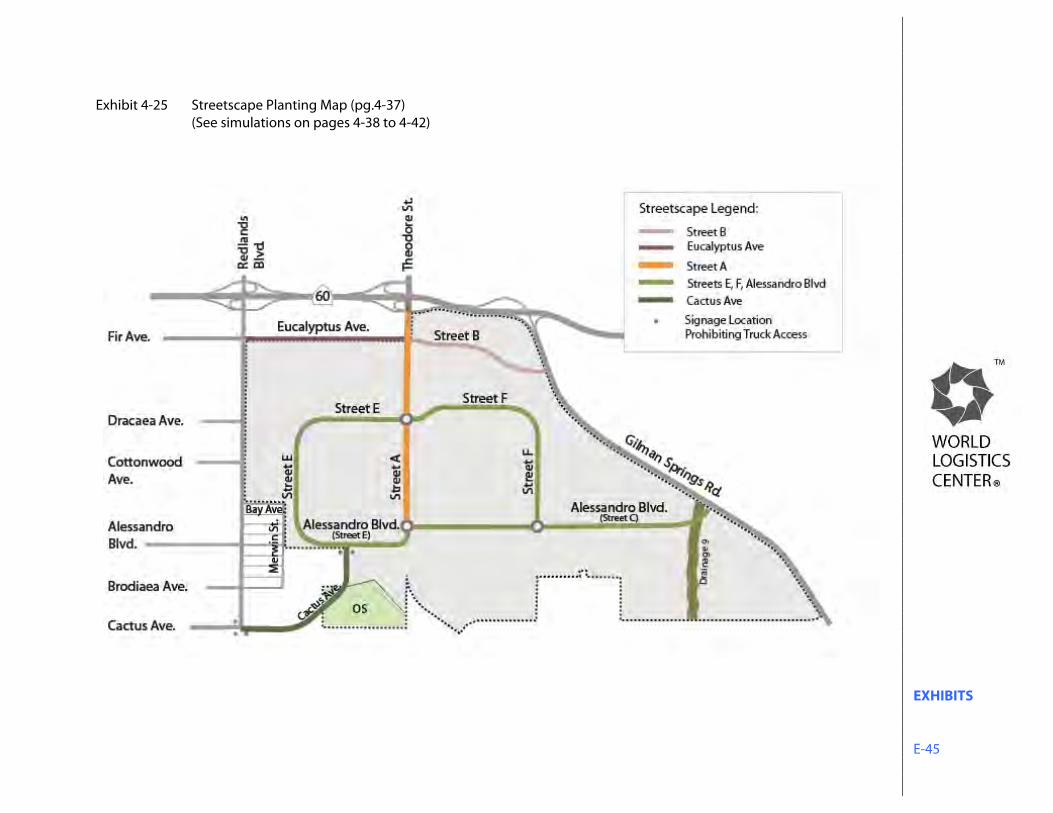
EXHIBITS E-45
Exhibit 4-25 Streetscape Planting Map (pg.4-37) (See simulations on pages 4-38 to 4-42)
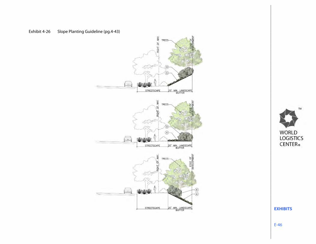
EXHIBITS E-46
Exhibit 4-26 Slope Planting Guideline (pg.4-43)
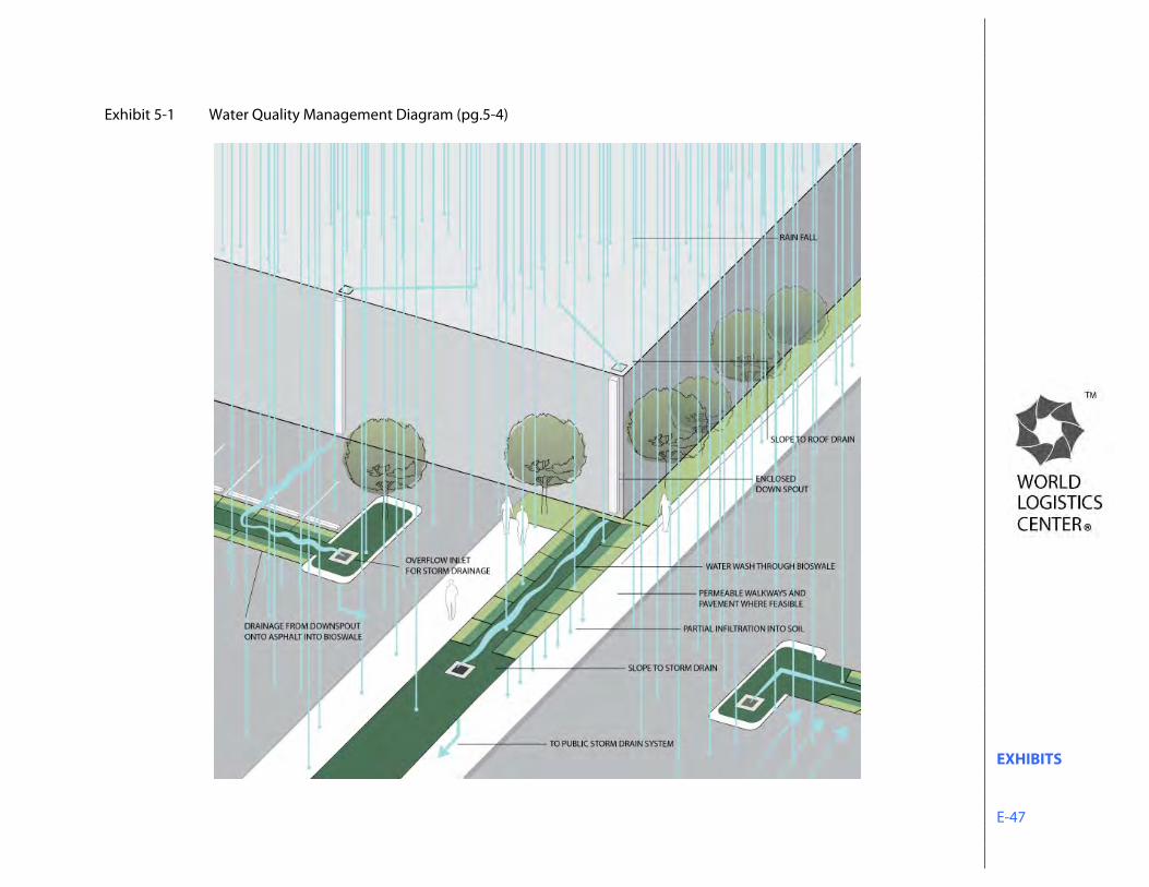
EXHIBITS E-47
Exhibit 5-1 Water Quality Management Diagram (pg.5-4)
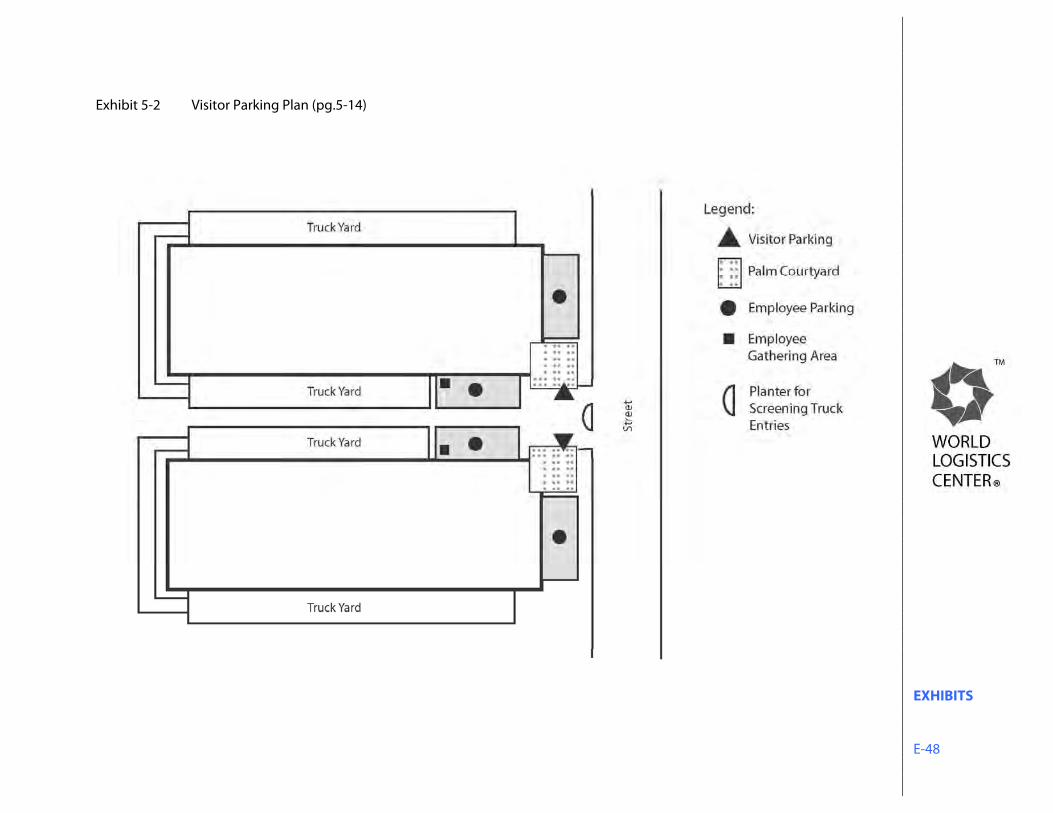
EXHIBITS E-48
Exhibit 5-2 Visitor Parking Plan (pg.5-14)
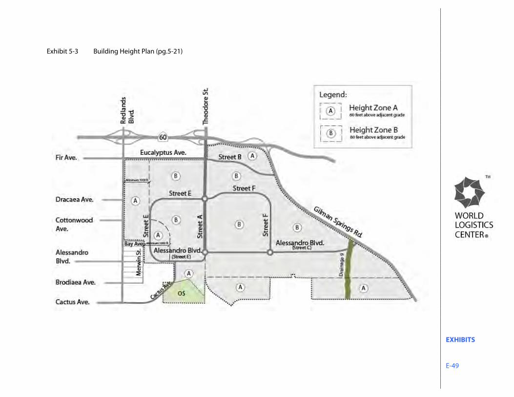
EXHIBITS E-49
Exhibit 5-3 Building Height Plan (pg.5-21)

EXHIBITS E-50
Exhibit 6-1 Off-site Water Management Plan (pg.6-1)
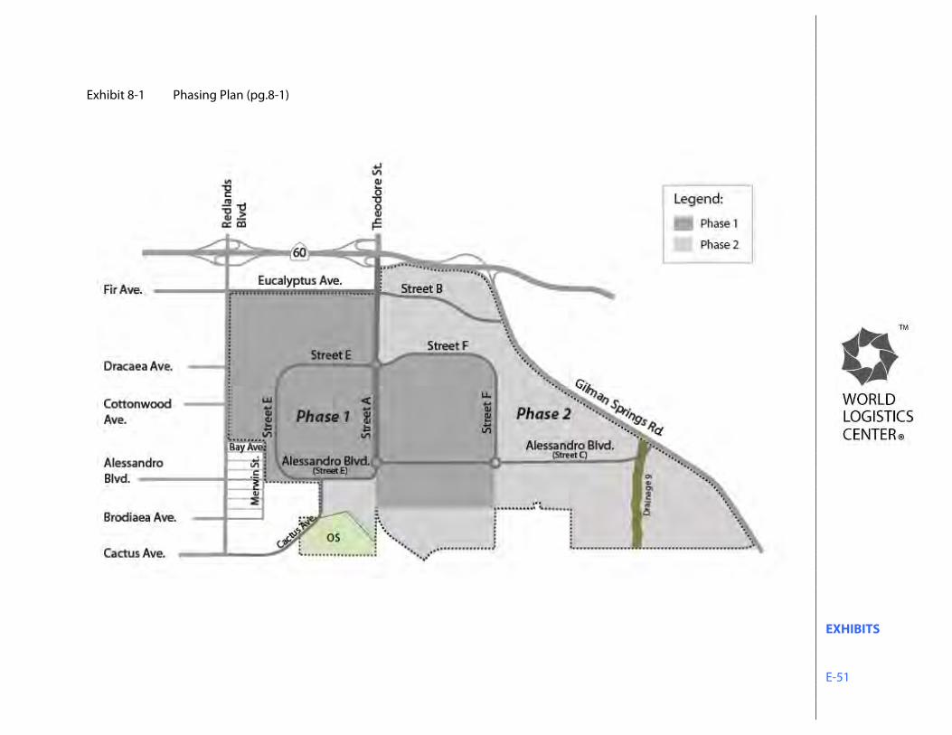
EXHIBITS E-51
Exhibit 8-1 Phasing Plan (pg.8-1)