Specific Design Guide
16
Information contained within is specific to the Futurebuild ® LVL range of products and must not be used with any other LVL products no matter how similar they may appear. Specific Design Guide AUSTRALIAN VERSION MARCH 2020 hySPAN STRUCTURAL LVL ® hySTRUCT STRUCTURAL LVL hySPAN STRUCTURAL LVL ® hy70 STRUCTURAL LVL ® truFLOOR ® STRUCTURAL LVL
Transcript of Specific Design Guide
Information contained within is specific to the Futurebuild® LVL range of products and must not be used with any other LVL products no matter how similar they may appear.
Specific Design GuideAUSTRALIAN VERSION M A R C H 2 0 2 0
hySPAN
STRUCTURALLVL
®
hySTRUCT
STRUCTURALLVL
hySPAN
STRUCTURALLVL
® hy70
STRUCTURALLVL
® truFLOOR®
STRUCTURALLVL
Contents1.0 Laminated Veneer Lumber....................... 31.1 Futurebuild® LVL .................................................. 31.2 Residential Buildings ............................................. 32.0 Engineering Design Tools .......................... 42.1 computeIT® Software Suite ................................. 42.2 computeIT for Beams .......................................... 42.3 computeIT toolkIT® ............................................. 43.0 Futurebuild® LVL Product Range ............. 53.1 Grades .................................................................. 53.2 Cross Banded Futurebuild LVL (X-Band) ........... 53.3 Purlin Design ......................................................... 63.4 Pre-fabrication Network ...................................... 63.5 Non Standard Sizes & Lengths ............................ 63.6 Futurebuild LVL Range Specifications.................. 64.0 General Design Considerations ................ 64.1 Characteristic Stresses ......................................... 64.2 Capacity Factor .................................................... 74.3 Duration of Load Factor ..................................... 74.4 Moisture Content ................................................. 74.5 Bearing Area ......................................................... 74.6 Load Sharing ......................................................... 74.7 Stability .................................................................. 74.8 Temperature ......................................................... 74.9 Size Factor ............................................................ 74.10 Fire Resistance ...................................................... 84.11 Joint Group ........................................................... 85.0 Characteristic Properties .......................... 85.1 Standard Section Sizes & Characteristic
Material Properties ............................................... 85.2 hySPAN® Limit State Design
Characteristic Properties ..................................... 95.3 hySPAN+® Limit States Design
Characteristic Properties ................................... 105.4 hy70® Limit States Design
Characteristic Properties ................................... 115.5 truFLOOR® Limit States Design
Characteristic Properties .................................. 125.6 hySTRUCT™ Limit States Design
Characteristic Properties ................................... 136.0 References .......................................................... 13
Specific Design Guide
FUTUREBUILD® LVL | SPECIFIC DESIGN GUIDE | www.fblvl.com.au | www.chhsoftware.com.au 3
LAM
INA
TED
VEN
EER LU
MBER
The information contained in this document is current as of March 2020 and is based on data available to Carter Holt Harvey (CHH) LVL Ltd trading as Futurebuild® LVL at the time of going to print. Futurebuild LVL reserves the right to change the information contained in this literature without prior notice.
It is important that you confirm that you have the most up to date information available, refer to www.fblvl.com.au.
Futurebuild LVL has used all reasonable endeavours to ensure the accuracy and reliability of the information contained in this document. This information does not replace professional advice and we recommend that professional advice should be obtained specific to your circumstances. To the extent permitted by law, Futurebuild will not be liable for any inaccuracies, omissions or errors in this information nor for any actions taken in reliance on this information.
1.0 LAMINATED VENEER LUMBER
Laminated Veneer Lumber (LVL) is an engineered wood material with defined and reliable strength and stiffness properties. It is suited to a wide range of structural applications, including critical elements such as large span portal frames and primary or secondary beams in commercial buildings.
For designers Futurebuild® LVL offers:
• Consistent structural performance with low variability.
• Third party certification of conformance with AS/NZS 4357 by the Engineered Wood Products Association of Australasia (EWPAA).
• Long lengths and large cross-sectional dimensions.
• Dimensionally stable product, which is easily installed on site.
1.1 FUTUREBUILD® LVL
Manufactured by Carter Holt Harvey® LVL Ltd, the Futurebuild LVL range of products features specific material property ‘recipes’. As such the information contained within this literature is specific to the Futurebuild LVL range and cannot be used with any other LVL product no matter how similar they may appear.
This literature contains general design information and material properties intended for use where members are specifically engineered for applications not covered by Futurebuild LVL product brochures.
For design information for standard applications visit www.fblvl.com.au.
1.2 RESIDENTIAL BUILDINGS
Software for the design of members for use in residential construction, including “designIT® for houses”, can be downloaded from www.chhsoftware.com.au. For specific engineering design, the computeIT® for beams software can be used to determine specific design requirements.
FUTUREBUILD® LVL | SPECIFIC DESIGN GUIDE | www.fblvl.com.au | www.chhsoftware.com.au 4
ENG
INEE
RIN
G D
ESIG
N T
OO
LS
2.0 ENGINEERING DESIGN TOOLS
2.1 computeIT® SOFTWARE SUITE
The computeIT® software suite consists of software packages; computeIT for beams and computeIT toolkIT®. It is designed to aid in the specification of heavy structural members and non-residential structural systems. It enables engineers, even those unfamiliar with the specifics of timber engineering to produce high quality, reliable specifications.
2.2 computeIT FOR BEAMS
computeIT for beams is an all purpose beam analysis package that enables engineers to develop design solutions for the Futurebuild® LVL range of engineered wood products. Made by engineers for engineers, computeIT for beams allows designers the flexibility of making design decisions. computeIT for beams provides users with an easy to use interface that allows engineers to:
• Enter complex beam design situations, including statically indeterminate beams and cantilevers.
• Enter a number of different load types including point loads, UDL’s and trapezoidal/triangular loads.
• Enter beam restraint information for calculation of capacities in accordance with AS1720.1-2010.
• Make engineering decisions based on engineering outputs including, deflection, bending moment and shear force diagrams.
• Design connections using a number of common connection details.
• Analyse a number of different members to produce cost effective design solutions.
• View graphical representation of beam geometry, loading and design action effect diagrams.
• Select loading combinations to AS/NZS 1170.• Apply design actions from other members within a job.• Create a job specific Engineering Analysis Report including
designed members and connections.
2.3 computeIT TOOLKIT®
computeIT toolkIT is a series of design tools to allow for the quick and easy design of portal frame members including moment resisting connections, portal frame members subject to combined actions, and purlins and girts. Developed by experienced timber design engineers using the most up to date information from design standards, computeIT toolkIT provides users with the opportunity to:
• Design moment resisting connections with commonly available materials and connectors.
• Design solid and built up members subject to combined actions, easily considering the effects of alternate restraint options.
• Select loading combinations for analysis to AS/NZS 1170, with automatic adoption of duration of load factor.
• Analyse different members to determine cost effective options.• Design solid and I-beam purlins and girts, including support and
restraint details.• Create a job specific Engineering Analysis Report including
designed members and connections.
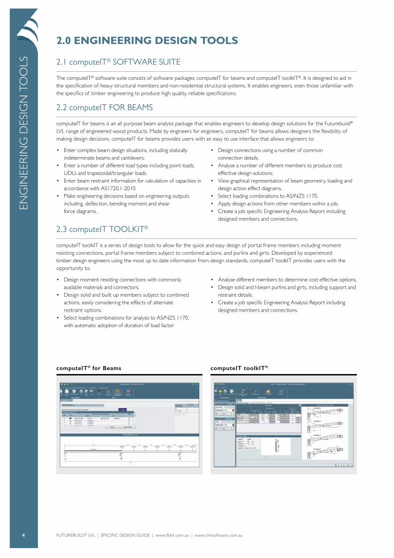
computeIT toolkIT®computeIT® for Beams

FUTUREBUILD® LVL | SPECIFIC DESIGN GUIDE | www.fblvl.com.au | www.chhsoftware.com.au 5
FUT
UR
EBUILD
® LVL PRO
DU
CT
RA
NG
E
3.0 FUTUREBUILD® LVL PRODUCT RANGE
Futurebuild® LVL made to order products for the commercial market include:
• hySPAN® sizes and gusset options to provide solid section solutions to 30m clear span.
• 900 x 90 hySPAN.• 42mm X-BAND hySPAN sheets for gusset connection.• Cross band (x-band) LVL for building spans over and above
30m where composite, built up sections may be required.
• Made to order composite plywood/LVL I-beams with design aids to suit.
• Thicknesses of Futurebuild LVL ranging from 28mm through to 90mm.
Table 1: Commonly Manufactured Futurebuild® LVL Thickness
Thickness Available in 2 X-Band Available in 4 X-Band
28mm
35mm
38mm
42mm
45mm
63mm
70mm
75mm
90mm
3.1 GRADES
CHH LVL Ltd produce a wide range of Futurebuild LVL products suitable for use in LVL structural systems including:
hySPAN+® (E=14.0 GPa) hySPAN® (E=13.2 GPa) hy70® (11.9 GPa) hySTRUCT™ (E=11.0 GPa) truFLOOR® (E=11.0 GPa)
These products are available for design and specification in any of the thicknesses specified above1, however for commercial applications we recommend the use of hySPAN for primary members and hySTRUCT or i-beam for secondary members. These tend to be more efficient from a design and cost perspective. For the complete range of Characteristic Design Properties refer below.
3.2 CROSS BANDED FUTUREBUILD® LVL (X-BAND)
Cross banded LVL is generally used for one of two different reasons:
Dimensional stability, where sections exhibit a depth to breadth ratio of > 10. The x-bands restrict the movement of moisture across the section effectively removing the cupping phenomenon.
The creation of connections, where the direction of the grain of the members being connected drives the nail spacing of the member (as typically applied in a plywood gusset).
There are also some other practical and theoretical reasons why cross bands are generally required in the creation of built up sections.
These reasons include:
Additional crosswise stiffness – The x-bands provide additional stiffness and strength across the grain. Typically, LVL is no different to timber in the fact that the cells run in the direction of the grain meaning that timber can be relatively easily broken across the grain. The existence of cross bands effectively ties these together. This is also advantageous from a practical perspective when handling product that can be up to 18.2m long as it increases the sturdiness of the sections.
X-bands enhance the shear capacity of ‘panels’, the cross laminates break up the tubular structure and provide additional resistance to shear. It should also be noted that the webs of a box beam are components that are required to carry shear, as well as bending and compression.

FUTUREBUILD® LVL | SPECIFIC DESIGN GUIDE | www.fblvl.com.au | www.chhsoftware.com.au 6
GEN
ERA
L D
ESIG
N C
ON
SID
ERA
TIO
NS
3.3 PURLIN DESIGN
Purlin design in LVL buildings is currently limited to readily available i-joists and solid sections. Typically i-joists have weight, strength (lateral restraint) and stiffness advantages over solid section purlins, however for smaller bays, solid sections can have installation advantages. The software package computeIT® toolkIT® includes the ability to design and specify Futurebuild® LVL products as purlins and girts.
Table 2: Purlin Span Guidance
Product Span
i-Beams(LVL flanged i-beams)
>7.0mm
hySPAN® (Solid LVL Section)
<7.0mm
MGP(Sawn Timber Sections)
<4.8mm
3.4 PRE-FABRICATION NETWORK
CHH LVL has preferred prefabricators who have access to the Futurebuild LVL range (including specific design products) in 100mm increments at fabrication rates for the development of
cost effective supplied solutions. For Fabrications in your region contact CHH LVL at [email protected].
3.5 NON STANDARD SIZES & LENGTHS
For commercial quantities, specific engineering designed product can be manufactured in sections up to 1200mm deep in thicknesses from 28mm thick through to 90mm thick, and in lengths up to 18.2m long. Practical limitations apply to the supply of product such as limiting cupping by keeping depth to breadth ratios at a maximum of 10 for non-cross banded LVL. Minimum order quantities and larger lead times apply to non-standard product. Contact CHH LVL for more information.
3.6 FUTUREBUILD® LVL RANGE SPECIFICATIONS
Futurebuild LVL products are manufactured in accordance with AS/NZS 4357 and have the structural design properties specified in 7, 9, 11 and 13. The following information relates to general Futurebuild LVL production.
Veneer Properties: Thickness ...............................................................3-4mm
Species: Radiata Pine Joints Face .............................................................Scarf Joints Other..........................................................Lap/Scarf
Moisture: Moisture Content1 ............................................8-15% 1At time of leaving mill
Nominal Dimensional Tolerances: Depth ......................................................................-0mm, + 2mm Thickness (<90) .................................................-0mm, + 2mm Thickness (>90) .................................................-2mm, + 2mm
Mass: Mass (approximate) .........................................600kg/m3
Adhesive & Bond: Refer AS/NZS 2098 ........................................Phenolic adhesive Type ‘A’ (marine) bond and AS 2754
4.0 GENERAL DESIGN CONSIDERATIONS
The design information given here is specific to the Futurebuild LVL range. To ensure that the required structural performance is met, designers must specify the product name.
4.1 CHARACTERISTIC STRESSES
The Futurebuild LVL characteristic stresses published are determined in accordance with Section 4 of AS/NZS 4063.2:2010. Note that:
• Characteristic Stresses may be different for use on flat or on edge as detailed.
• MoE is a mean value which includes an allowance for shear deformation.
• Because of the low variability of LVL a lower bound E is not required for most applications, however where required, the lower 5th percentile Modulus of Elasticity may be taken as 0.85 E.
• Selection of Characteristics Stress Values should take into account the allowance for the representativeness of the sample population, allowance for levels of control of process and quality, amongst other things. Substitution with similar properties from alternate manufacturers may not provide the calculated design performance. These characteristic stresses are not for use with products from alternative manufacturers.
FUTUREBUILD® LVL | SPECIFIC DESIGN GUIDE | www.fblvl.com.au | www.chhsoftware.com.au 7
GEN
ERA
L DESIG
N C
ON
SIDER
AT
ION
S
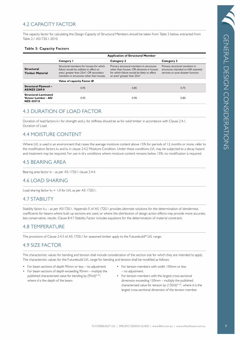
4.2 CAPACITY FACTOR
The capacity factor for calculating the Design Capacity of Structural Members should be taken from Table 3 below, extracted from Table 2.1 AS1720.1-2010.
Table 3: Capacity Factors
Application of Structural Member
Category 1 Category 2 Category 3
StructuralTimber Material
Structural members for houses for which failure would be unlikely to affect an area1 greater than 25m2; OR secondary members in structures other than houses
Primary structural members in structures other than houses; OR elements in houses for which failure would be likely to affect an area* greater than 25m2
Primary structural members in structures intended to fulfil essential services or post disaster function
Value of capacity Factor Ø
Structural Plywood – AS/NZS 2269.0 0.95 0.85 0.75
Structural Laminated Veneer Lumber - AS/NZS 4357.0
0.95 0.90 0.80
4.3 DURATION OF LOAD FACTOR
Duration of load factors k1 for strength and j2 for stiffness should be as for solid timber in accordance with Clause 2.4.1, Duration of Load.
4.4 MOISTURE CONTENT
Where LVL is used in an environment that raises the average moisture content above 15% for periods of 12 months or more, refer to the modification factors k4 and k6 in clause 2.4.2 Moisture Condition. Under these conditions LVL may be subjected to a decay hazard and treatment may be required. For use in dry conditions where moisture content remains below 15%, no modification is required.
4.5 BEARING AREA
Bearing area factor k7 - as per AS 1720.1 clause 2.4.4.
4.6 LOAD SHARING
Load sharing factor k9 = 1.0 for LVL as per AS 1720.1.
4.7 STABILITY
Stability factor k12 - as per AS1720.1. Appendix E of AS 1720.1 provides alternate solutions for the determination of slenderness coefficients for beams where built up sections are used, or where the distribution of design action effects may provide more accurate, less conservative, results. Clause 8.4.7 Stability Factor includes equations for the determination of material constraint.
4.8 TEMPERATURE
The provisions of Clause 2.4.3 of AS 1720.1 for seasoned timber apply to the Futurebuild® LVL range.
4.9 SIZE FACTOR
The characteristic values for bending and tension shall include consideration of the section size for which they are intended to apply. The characteristic values for the Futurebuild LVL range for bending and tension shall be modified as follows:
• For beam sections of depth 95mm or less – no adjustment• For beam sections of depth exceeding 95mm – multiply the
published characterised value for bending by (95/d)0.154, where d is the depth of the beam.
• For tension members with width 150mm or less – no adjustment.
• For tension members with the largest cross-sectional dimension exceeding 150mm – multiply the published characterised value for tension by (150/d)0.167, where d is the largest cross-sectional dimension of the tension member.

FUTUREBUILD® LVL | SPECIFIC DESIGN GUIDE | www.fblvl.com.au | www.chhsoftware.com.au 8
CH
AR
AC
TER
IST
IC P
ROPE
RTIE
S4.10 FIRE RESISTANCE
The method for calculating the fire resistance of LVL products is described in AS 1720.4. Recommendations derived from a testing programme on Futurebuild® LVL at the University of
Canterbury are:
• The design method used for predicting the fire performance of Futurebuild LVL exposed to post-flashover fires is to use the experimentally found char rate ß = 0.72mm/minute to determine a reduced cross-section, and design using normal
temperature properties without considering a heat-affected layer of wood below the char line.
• Design using the char rate ß = 0.65mm/minute (complying with AS 1720.4) to calculate a reduced cross section which can be used with normal temperature properties, with an allowance for a 7.5mm zerostrength layer of Futurebuild LVL below the char line.
This data has not been tested on, and is not applicable to LVL made by other manufacturers.
4.11 JOINT GROUP
The joint strength group is dependent on the Futurebuild LVL product, the type of fastener and the grain orientation at the joint.
Table 4: Classification of LVL Products for Joint Design
Product Nails & Screws in Lateral Load
Type 17 Screws in
Lateral Load
Nails & Screws in Withdrawal
Type 17 Screws in Withdrawal
Bolts & Coach Screws in Lateral Load Driven into Face
Edge Face Edge & Face Parallel to Grain
Perpendicular to grain
hy70®/hySPAN®/hySPAN+® JD4 JD4 JD4 JD3 JD3 JD3 JD1
truFLOOR®/hySTRUCT™ JD4 JD4 JD4 JD3 JD3 JD3 JD2
5.0 CHARACTERISTIC PROPERTIES
5.1 STANDARD SECTION SIZES & CHARACTERISTIC MATERIAL PROPERTIES
CHH LVL Ltd manufactures six Futurebuild LVL product lines for structural applications, each with specific properties and section sizes.
hySPAN+® offers an alternative to F17 hardwood beams. It provides the extra performance of LVL with modified properties and sizes to suit F17 conversion.
hySPAN® is CHH LVL’s NZ’s most versatile LVL product. It has high structural properties and is available in the largest range of sizes and lengths. hySPAN is typically specified for structural beams and is also used for lintels, rafters and floor joists in residential structures.
Hy70® is a laminated veneer lumber (LVL) product designed for use in structural beams where the builder wants high and consistent performance, coupled with a material that fits within 70mm framing. Applications will typically be for load-bearing lintels in houses or for beams where 70mm width is desired.
hySTRUCT™ is an all-purpose LVL product targeted at traditional timber sizes for high load applications where strength and predictable deflection performance are paramount.
truFLOOR® is an LVL product targeted at bearer and joist sub floor applications where predictable performance is advantageous.
hySPAN
STRUCTURALLVL
®
hySTRUCT
STRUCTURALLVL
hySPAN
STRUCTURALLVL
®
truFLOOR®
STRUCTURALLVL
hy70
STRUCTURALLVL
®
FUTUREBUILD® LVL | SPECIFIC DESIGN GUIDE | www.fblvl.com.au | www.chhsoftware.com.au 9
CH
AR
AC
TER
ISTIC
PROPERT
IES
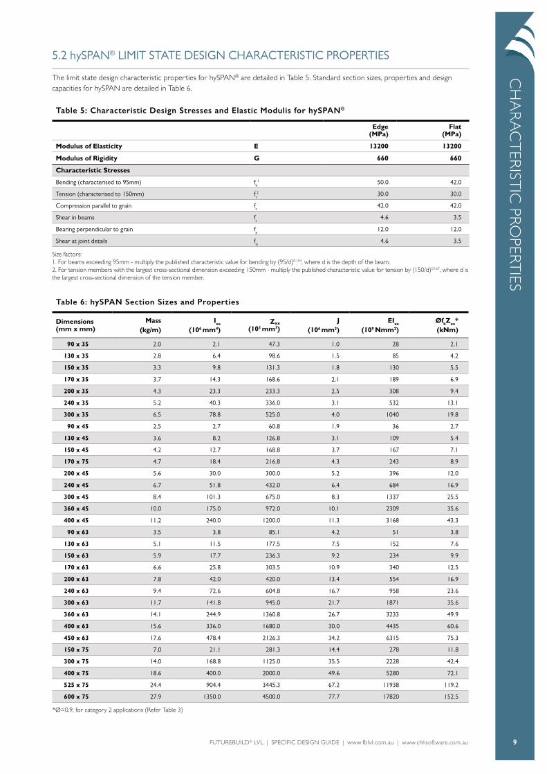
5.2 hySPAN® LIMIT STATE DESIGN CHARACTERISTIC PROPERTIES
The limit state design characteristic properties for hySPAN® are detailed in Table 5. Standard section sizes, properties and design capacities for hySPAN are detailed in Table 6.
Table 5: Characteristic Design Stresses and Elastic Modulis for hySPAN®
Edge (MPa)
Flat (MPa)
Modulus of Elasticity E 13200 13200
Modulus of Rigidity G 660 660
Characteristic Stresses
Bending (characterised to 95mm) fb1 50.0 42.0
Tension (characterised to 150mm) ft2 30.0 30.0
Compression parallel to grain fc 42.0 42.0
Shear in beams fs 4.6 3.5
Bearing perpendicular to grain fp 12.0 12.0
Shear at joint details fsj 4.6 3.5
Size factors: 1. For beams exceeding 95mm - multiply the published characteristic value for bending by (95/d)0.154, where d is the depth of the beam. 2. For tension members with the largest cross-sectional dimension exceeding 150mm - multiply the published characteristic value for tension by (150/d)0.167, where d is the largest cross-sectional dimension of the tension member.
Table 6: hySPAN Section Sizes and Properties
Dimensions (mm x mm)
Mass(kg/m)
Ixx
(106 mm4)Zxx
(103 mm3)J
(106 mm3)EIxx
(109 Nmm2)ØfbZxx*(kNm)
90 x 35 2.0 2.1 47.3 1.0 28 2.1
130 x 35 2.8 6.4 98.6 1.5 85 4.2
150 x 35 3.3 9.8 131.3 1.8 130 5.5
170 x 35 3.7 14.3 168.6 2.1 189 6.9
200 x 35 4.3 23.3 233.3 2.5 308 9.4
240 x 35 5.2 40.3 336.0 3.1 532 13.1
300 x 35 6.5 78.8 525.0 4.0 1040 19.8
90 x 45 2.5 2.7 60.8 1.9 36 2.7
130 x 45 3.6 8.2 126.8 3.1 109 5.4
150 x 45 4.2 12.7 168.8 3.7 167 7.1
170 x 75 4.7 18.4 216.8 4.3 243 8.9
200 x 45 5.6 30.0 300.0 5.2 396 12.0
240 x 45 6.7 51.8 432.0 6.4 684 16.9
300 x 45 8.4 101.3 675.0 8.3 1337 25.5
360 x 45 10.0 175.0 972.0 10.1 2309 35.6
400 x 45 11.2 240.0 1200.0 11.3 3168 43.3
90 x 63 3.5 3.8 85.1 4.2 51 3.8
130 x 63 5.1 11.5 177.5 7.5 152 7.6
150 x 63 5.9 17.7 236.3 9.2 234 9.9
170 x 63 6.6 25.8 303.5 10.9 340 12.5
200 x 63 7.8 42.0 420.0 13.4 554 16.9
240 x 63 9.4 72.6 604.8 16.7 958 23.6
300 x 63 11.7 141.8 945.0 21.7 1871 35.6
360 x 63 14.1 244.9 1360.8 26.7 3233 49.9
400 x 63 15.6 336.0 1680.0 30.0 4435 60.6
450 x 63 17.6 478.4 2126.3 34.2 6315 75.3
150 x 75 7.0 21.1 281.3 14.4 278 11.8
300 x 75 14.0 168.8 1125.0 35.5 2228 42.4
400 x 75 18.6 400.0 2000.0 49.6 5280 72.1
525 x 75 24.4 904.4 3445.3 67.2 11938 119.2
600 x 75 27.9 1350.0 4500.0 77.7 17820 152.5
*Ø=0.9, for category 2 applications (Refer Table 3)

FUTUREBUILD® LVL | SPECIFIC DESIGN GUIDE | www.fblvl.com.au | www.chhsoftware.com.au 10
5.3 hySPAN+® LIMIT STATES DESIGN CHARACTERISTIC PROPERTIES
The limit state design characteristic properties for hySPAN+® are detailed in Table 7. Standard section sizes, properties and design capacities for hySPAN+ are detailed in Table 8.
Table 7: Characteristic Design Stresses and Elastic Modulis for hySPAN+®
Edge (MPa)
Flat (MPa)
Modulus of Elasticity E 14,000 14,000
Modulus of Rigidity G 700 700
Characteristic Stresses
Bending (characterised to 95mm) fb1 52.0 46.0
Tension (characterised to 150mm) ft2 30.0 30.0
Compression parallel to grain fc 48.0 48.0
Shear in beams fs 4.6 3.2
Bearing perpendicular to grain fp 12.0 12.0
Shear at joint details fsj 4.6 3.2
Size factors: 1. For beams exceeding 95mm - multiply the published characteristic value for bending by (95/d)0.154, where d is the depth of the beam. 2. For tension members with the largest cross-sectional dimension exceeding 150mm - multiply the published characteristic value for tension by (150/d)0.167, where d is the largest cross-sectional dimension of the tension member.
Table 8: hySPAN+ Section Sizes and Properties
Dimensions (mm x mm)
Mass(kg/m)
Ixx
(106 mm4)Zxx
(103 mm3)J
(106 mm3)EIxx
(109 Nmm2)ØfbZxx*(kNm)
90 x 35 2.0 2.1 47.3 1.0 30 2.2
120 x 35 2.6 5.0 84.0 1.4 71 3.8
140 x 35 3.0 8.0 114.3 1.7 112 5.0
190 x 35 4.1 20.0 210.6 2.4 280 8.9
240 x 35 5.2 40.3 336.0 3.1 564 13.6
290 x 35 6.3 71.1 490.6 3.8 996 19.3
70 x 45 2.0 1.3 36.8 1.3 18 1.7
90 x 45 2.5 2.7 60.8 1.9 38 2.8
120 x 45 3.3 6.5 108.0 2.8 91 4.9
140 x 45 3.9 10.3 147.0 3.4 144 6.5
190 x 45 5.3 25.7 270.8 4.9 360 11.4
240 x 45 6.7 51.8 432.0 6.4 726 17.5
290 x 45 8.1 91.5 630.8 7.9 1280 24.9
*Ø=0.9, for category 2 applications (Refer Table 3)
CH
AR
AC
TER
IST
IC P
ROPE
RTIE
S
FUTUREBUILD® LVL | SPECIFIC DESIGN GUIDE | www.fblvl.com.au | www.chhsoftware.com.au 11
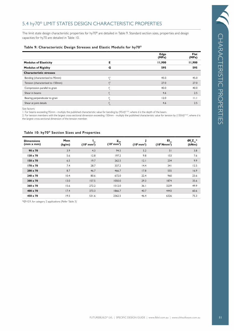
5.4 hy70® LIMIT STATES DESIGN CHARACTERISTIC PROPERTIES
The limit state design characteristic properties for hy70® are detailed in Table 9. Standard section sizes, properties and design capacities for hy70 are detailed in Table 10.
Table 9: Characteristic Design Stresses and Elastic Modulis for hy70®
Edge (MPa)
Flat (MPa)
Modulus of Elasticity E 11,900 11,900
Modulus of Rigidity G 595 595
Characteristic stresses
Bending (characterised to 95mm) fb1 45.0 45.0
Tension (characterised to 150mm) ft2 27.0 27.0
Compression parallel to grain fc 40.0 40.0
Shear in beams fs 4.6 2.5
Bearing perpendicular to grain fp 12.0 11.1
Shear at joint details fsj 4.6 2.5
Size factors: 1. For beams exceeding 95mm - multiply the published characteristic value for bending by (95/d)0.154, where d is the depth of the beam. 2. For tension members with the largest cross-sectional dimension exceeding 150mm - multiply the published characteristic value for tension by (150/d)0.167, where d is the largest cross-sectional dimension of the tension member.
Table 10: hy70® Section Sizes and Properties
Dimensions (mm x mm)
Mass(kg/m)
Ixx
(106 mm4)Zxx
(103 mm3)J
(106 mm3)EIxx
(109 Nmm2)ØfbZxx*(kNm)
90 x 70 3.9 4.3 94.5 5.2 51 3.8
130 x 70 5.6 12.8 197.2 9.8 153 7.6
150 x 70 6.5 19.7 262.5 12.1 234 9.9
170 x 70 7.4 28.7 337.2 14.4 341 12.5
200 x 70 8.7 46.7 466.7 17.8 555 16.9
240 x 70 10.4 80.6 672.0 22.4 960 23.6
300 x 70 13.0 157.5 1050.0 29.3 1874 35.6
360 x 70 15.6 272.2 1512.0 36.1 3239 49.9
400 x 70 17.4 373.3 1866.7 40.7 4443 60.6
450 x 70 19.5 531.6 2362.5 46.4 6326 75.3
*Ø=0.9, for category 2 applications (Refer Table 3)
CH
AR
AC
TER
ISTIC
PROPERT
IES
FUTUREBUILD® LVL | SPECIFIC DESIGN GUIDE | www.fblvl.com.au | www.chhsoftware.com.au 12
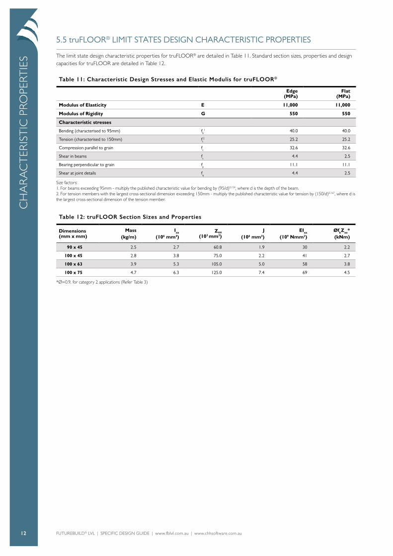
5.5 truFLOOR® LIMIT STATES DESIGN CHARACTERISTIC PROPERTIES
The limit state design characteristic properties for truFLOOR® are detailed in Table 11. Standard section sizes, properties and design capacities for truFLOOR are detailed in Table 12.
Table 11: Characteristic Design Stresses and Elastic Modulis for truFLOOR®
Edge (MPa)
Flat (MPa)
Modulus of Elasticity E 11,000 11,000
Modulus of Rigidity G 550 550
Characteristic stresses
Bending (characterised to 95mm) fb1 40.0 40.0
Tension (characterised to 150mm) ft2 25.2 25.2
Compression parallel to grain fc 32.6 32.6
Shear in beams fs 4.4 2.5
Bearing perpendicular to grain fp 11.1 11.1
Shear at joint details fsj 4.4 2.5
Size factors: 1. For beams exceeding 95mm - multiply the published characteristic value for bending by (95/d)0.154, where d is the depth of the beam. 2. For tension members with the largest cross-sectional dimension exceeding 150mm - multiply the published characteristic value for tension by (150/d)0.167, where d is the largest cross-sectional dimension of the tension member.
Table 12: truFLOOR Section Sizes and Properties
Dimensions (mm x mm)
Mass(kg/m)
Ixx
(106 mm4)Zxx
(103 mm3)J
(106 mm3)EIxx
(109 Nmm2)ØfbZxx*(kNm)
90 x 45 2.5 2.7 60.8 1.9 30 2.2
100 x 45 2.8 3.8 75.0 2.2 41 2.7
100 x 63 3.9 5.3 105.0 5.0 58 3.8
100 x 75 4.7 6.3 125.0 7.4 69 4.5
*Ø=0.9, for category 2 applications (Refer Table 3)
CH
AR
AC
TER
IST
IC P
ROPE
RTIE
S
FUTUREBUILD® LVL | SPECIFIC DESIGN GUIDE | www.fblvl.com.au | www.chhsoftware.com.au 13
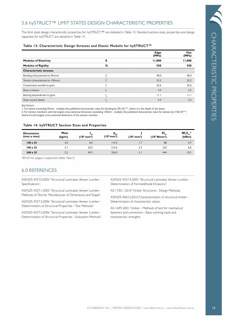
5.6 hySTRUCT™ LIMIT STATES DESIGN CHARACTERISTIC PROPERTIES
The limit state design characteristic properties for hySTRUCT™ are detailed in Table 13. Standard section sizes, properties and design capacities for hySTRUCT are detailed in Table 14.
Table 13: Characteristic Design Stresses and Elastic Modulis for hySTRUCT™
Edge (MPa)
Flat (MPa)
Modulus of Elasticity E 11,000 11,000
Modulus of Rigidity G 550 550
Characteristic stresses
Bending (characterised to 95mm) fb1 40.0 40.0
Tension (characterised to 150mm) ft2 25.2 25.2
Compression parallel to grain fc 32.6 32.6
Shear in beams fs 4.4 2.5
Bearing perpendicular to grain fp 11.1 11.1
Shear at joint details fsj 4.4 2.5
Size factors: 1. For beams exceeding 95mm - multiply the published characteristic value for bending by (95/d)0.154, where d is the depth of the beam. 2. For tension members with the largest cross-sectional dimension exceeding 150mm - multiply the published characteristic value for tension by (150/d)0.167, where d is the largest cross-sectional dimension of the tension member.
Table 14: hySTRUCT Section Sizes and Properties
Dimensions (mm x mm)
Mass(kg/m)
Ixx
(106 mm4)Zxx
(103 mm3)J
(106 mm3)EIxx
(109 Nmm2)ØfbZxx*(kNm)
140 x 35 3.0 8.0 114.3 1.7 88 3.9
190 x 35 4.1 20.0 210.6 2.4 220 6.8
240 x 35 5.2 40.3 336.0 3.1 444 10.5
*Ø=0.9, for category 2 applications (Refer Table 3)
6.0 REFERENCES
AS/NZS 4357.0:2005 “Structural Laminates Veneer Lumber - Specifications”.
AS/NZS 4357.1:2005 “Structural Laminates Veneer Lumber - Methods of Test for Manufacturer of Dimensions and Shape”.
AS/NZS 4357.2:2006 “Structural Laminates Veneer Lumber - Determination of Structural Properties - Test Methods”.
AS/NZS 4357.3:2006 “Structural Laminates Veneer Lumber - Determination of Structural Properties - Evaluation Methods”.
AS/NZS 4357.4:2005 “Structural Laminates Veneer Lumber - Determination of Formaldehyde Emissions”.
AS 1720.1-2010 Timber Structures - Design Methods.
AS/NZS 4063.2:2010 Characterisation of structural timber - Determination of characteristic values.
AS 1649-2001 Timber - Methods of test for mechanical fasteners and connectors - Basic working loads and characteristic strengths.
CH
AR
AC
TER
ISTIC
PROPERT
IES

FUTUREBUILD® LVL | SPECIFIC DESIGN GUIDE | www.fblvl.com.au | www.chhsoftware.com.au 14
FUTUREBUILD® LVL | SPECIFIC DESIGN GUIDE | www.fblvl.com.au | www.chhsoftware.com.au 15

PO Box 425Box Hill VIC 3128Australia
www.fblvl.com.auwww.chhsoftware.com.au
© March 2020