
Multilayer Neural Networks (sometimes called “Multilayer Perceptrons” or MLPs)

IPC-4101
Specification for Base
Materials for Rigid and
Multilayer Printed Boards
IPC-4101December 1997
SupercedesIPC-L-108, IPC-L-109,IPC-L-112, IPC-L-115IPC-AM-361
The Institute for
Interconnecting
and Packaging
Electronic Circuits
A standard developed by the Institute for Interconnectingand Packaging Electronic Circuits
2215 Sanders RoadNorthbrook, Illinois60062-6135
TelFaxURL:
847 509.9700847 509.9798http://www.ipc.org

Standardization In May 1995 the IPC’s Technical Activities Executive Committee adopted Prin-ciples of Standardization as a guiding principle of IPC’s standardization efforts.
Standards Should:• Show relationship to DFM & DFE• Minimize time to market• Contain simple (simplified) language• Just include spec information• Focus on end product performance• Include a feed back system on use and problems for future improvement
Standards Should Not:• Inhibit innovation• Increase time-to-market• Keep people out• Increase cycle time• Tell you how to make something• Contain anything that cannot be defended with data
Notice IPC Standards and Publications are designed to serve the public interest througheliminating misunderstandings between manufacturers and purchasers, facilitat-ing interchangeability and improvement of products, and assisting the pur-chaser in selecting and obtaining with minimum delay the proper product forhis particular need. Existence of such Standards and Publications shall notin any respect preclude any member or nonmember of IPC from manufacturingor selling products not conforming to such Standards and Publication, norshall the existence of such Standards and Publications preclude their voluntaryuse by those other than IPC members, whether the standard is to be usedeither domestically or internationally.
Recommended Standards and Publications are adopted by IPC without regard towhether their adoption may involve patents on articles, materials, or processes.By such action, IPC does not assume any liability to any patent owner, nordo they assume any obligation whatever to parties adopting the RecommendedStandard or Publication. Users are also wholly responsible for protectingthemselves against all claims of liabilities for patent infringement.
The material in this standard was developed by the Laminate/Prepreg MaterialsSubcommittee (3-11) of the Printed Board Base Materials Committee of theInstitute for Interconnecting and Packaging Electronic Circuits.
Copyright © 1997 by the Institute for Interconnecting and Packaging Electronic Circuits. All rights reserved. Published 1997. Printed in theUnited States of America.
No part of this publication may be reproduced in any form, in an electronic retrieval system or otherwise, without the prior written permissionof the publisher.

IPC-4101
Specification for Base
Materials for Rigid and
Multilayer Printed Boards
Developed by the Laminate/Prepreg Materials Subcommittee (3-11)of the Printed Board Base Materials Committee of the Institute forInterconnecting and Packaging Electronic Circuits
Users of this standard are encouraged to participate in thedevelopment of future revisions.
Contact:
IPC2215 Sanders RoadNorthbrook, Illinois60062-6135Tel 847 509.9700Fax 847 509.9798
THE INSTITUTE FOR
INTERCONNECTING
AND PACKAGING
ELECTRONIC CIRCUITS
AcknowledgmentAny Standard involving a complex technology draws material from a vast number of sources. While the principal membersof the Laminate/Prepreg Materials Subcommittee and the Printed Board Base Material Committee are shown below, it is notpossible to include all of those who assisted in the evolution of this Standard. To each of them, the members of the IPCextend their gratitude.
Printed Board BaseMaterial Committee
Laminate/PrepregMaterials Subcommittee
Technical Liaison of theIPC Board of Directors
ChairmanDoug SoberisolaUSA
ChairmanErik BergumPolyclad Laminates, Inc.
Jim DonaghySheldahl Inc.
Laminate/Prepreg Materials Subcommittee
Joanne Andrews, Hadco Corp.Masamitsu Aoki, Toshiba ChemicalCorp.
Ivan Araktingi, AlliedSignal LaminateSystems
Erik Bergum, Polyclad Laminates Inc.David Blank, TRWGerald Bouska, AlliedSignal LaminateSystems
Jack Bramel, Jack Bramel & AssociatesThomas Bresnan, Multek, Inc.Carl Brooks, Northrop GrummanElectronic Sensors & Systems Div
Mike Bryant, BGF Industries Inc.Victor Brzozowski, Northrop GrummanElectronic Sensors & Systems Div
Thomas Burke, Polyonics CorporationGary Burreson, Nelco Technology Inc.Charles Rick Burton, AlliedSignal, OakMitsui Inc.
Linda Cartwright Dunn, CompaqComputer Corporation
Walter Christiansen, Shell ChemicalCompany
John Christmas, U.S. Air ForceDave Corbett, DSCCDavid Dalman, Dow Chemical Co.Dale Daugherty, Siemens Energy &Automation
Nitin Desai, Motorola Inc.Paul DuFresne, Circuit Foil USA Inc.Robert Dunnagan, BGF Industries Inc.Terry Fischer, Hitachi Chemical Co.America
Floyd Gentry, Sandia National LabsAlbuquerque
Richard Grannells, United TechnologiesDonald Greene, Rogers CorporationJason Gretton, Matsushita ElectronicMaterials Inc.
Chester Guiles, Arlon Inc.
William Hall, AlliedSignal, Oak MitsuiInc.
Les Hymes, Les Hymes AssociatesSteven Ising, Borden Chemical, Inc.William Jacobi, Sheldahl Inc.Dan Jacobus, Sheldahl Inc.Martin Jawitz, Eimer CompanyLaurence Johnson, General Electric Co.Roger Jones, InterconnectionTechnology Research Institute
Yvonne Julian-Hargrove, DowChemical USA
Ulrich Kempf, FiberMark, Inc.Robert Konsowitz, Glasteel IndustrialLaminates
Steve Koonce, Ciba-Geigy Corp.John Kuhn, PPG Industries Inc.Thomas Kurtz, Hughes DefenseCommunications
Paul Kyle, Arlon Inc.Edward Lewis, isolaUSARobert Lozano, West Coast EnterprisesRichard Lucier, Compositech Ltd.P. Douglas Lyle, Owens-CorningFiberglass Corp.
James Maguire, Boeing Defense &Space Group
Rene Martinez, TRWScott McElvie, Matsushita ElectronicMaterials Inc.
David McGowan, DRM ConsultingJoseph Mulcahy, Methode ElectronicsInc. East
Joel Murray, Clark-Schwebel Inc.Bob Neves, Microtek LaboratoriesThomas Nowak, Nowak & AssociatesScott Opperhauser, Trace Laboratories -East
Kiyoshi Osaka, Shin-Kobe ElectricMachinery Co. Ltd.
John Lee Parker, ViasystemsTechnologies Corp.
James Paulus, AlliedSignal LaminateSystems
Anthony Pigneri, Shell ChemicalCompany
Paul Quinn, Lockheed Martin Missiles& Space
Dawn Racine, Polyclad Laminates Inc.Randy Reed, Merix CorporationPaul Reichenbacher, AlliedSignalLaminate Systems
Paul Rose, Lockheed MartinElectronics & Missiles
Andrew Ruman, Elexsys InternationalInc.
Katherine Sack, Gould Electronics Inc.Jerome Sallo, Sallo Consulting ServicesEarl Sauer, Viasystems TechnologiesCorp.
Rolland Savage, Gould Electronics Inc.D. Eric Seip, Polyclad Laminates Inc.Tony Senese, TaconicScott Sharot, AIL Systems Inc.William Shaw, FiberMark, Inc.Nusrat Sherali, MultekLowell Sherman, DSCCMichael Shin, Pacific TestingLaboratories, Inc.
Andrew Slade, Hadco CorporationGrant (Rick) Smedley, Raytheon TISystems
Douglas Sober, isolaUSAGeorge Stoddart, Canadian StandardAssociation
Richard Thompson, Loctite CorporationRoger Tietze, Ciba-Geigy Corp.James (Tom) Turner, isolaUSARichard Widden, AlliedSignal, OakMitsui Inc.
IPC-4101 December 1997
ii

Table of Contents
1.0 GENERAL ................................................................. 11.1 Scope.................................................................... 1
1.2 Classification ........................................................ 1
1.2.1 Specification Sheet Description........................... 1
1.2.2 Nominal Laminate Thickness.............................. 1
1.2.3 Metal Cladding Type ........................................... 1
1.2.4 Thickness Tolerance (Laminate) ......................... 2
1.2.5 Surface Quality Class .......................................... 2
1.2.6 Reinforcement Style ............................................ 2
1.2.7 Prepreg Parameters .............................................. 2
1.2.8 Color..................................................................... 2
1.3 Dimensions and Tolerances ................................. 2
2.0 APPLICABLE DOCUMENTS ................................... 22.1 IPC........................................................................ 2
2.2 National Conference of StandardsLaboratories ........................................................ 3
2.3 International Standards ....................................... 4
3.0 REQUIREMENTS .................................................... 43.1 Terms and Definitions.......................................... 4
3.1.1 Qualification Assessment..................................... 4
3.1.2 Quality Conformance Testing.............................. 4
3.1.3 Manufacturer’s Quality System........................... 4
3.1.4 Process Control Testing ....................................... 4
3.1.5 Self Declaration ................................................... 4
3.1.6 Quality Assessment Data..................................... 4
3.1.7 Sample Qualification............................................ 4
3.1.8 Production Data ................................................... 4
3.1.9 Customer Test Data ............................................. 4
3.1.10 Internal Assessment ............................................. 4
3.1.11 Individual Customer Audit .................................. 4
3.1.12 Independent Third Party Assessment .................. 4
3.2 Specification Sheets ............................................. 4
3.3 Manufacturers Quality Profile ............................. 5
3.4 Qualification Testing............................................ 5
3.4.1 Qualification Testing Laminate ........................... 5
3.4.2 Qualification Testing Prepreg .............................. 5
3.5 Verification of Manufacturer’s Quality System .. 5
3.6 Conflict................................................................. 5
3.7 Materials............................................................... 5
3.7.1 Metal-cladding ..................................................... 5
3.7.2 Reinforcement Fabric .......................................... 5
3.7.3 Resin Systems...................................................... 5
3.8 General Requirements/Acceptability ................... 5
3.8.1 Fabricated Sheets and Panels .............................. 5
3.8.2 Inspection Lot ...................................................... 6
3.8.3 Visual Properties ................................................. 6
3.8.4 Dimensional ......................................................... 7
3.9 Physical Requirements....................................... 12
3.9.1 Physical Requirements Laminate Materials .... 12
3.9.2 Physical Requirements Prepreg Materials ........ 12
3.10 Chemical Requirements..................................... 13
3.10.1 Chemical Requirements Laminate Materials ... 13
3.10.2 Chemical Requirements Prepreg Materials....... 14
3.11 Electrical Requirements .................................... 14
3.11.1 Electrical Requirements Laminate Materials ... 14
3.11.2 Electrical Requirements Prepreg Materials....... 14
3.12 Environmental Requirements ............................ 14
3.12.1 Environmental Requirements LaminateMaterials ........................................................... 14
3.12.2 Environmental Requirements PrepregMaterials............................................................. 14
3.12.3 Visual and Dimensional RequirementsLaminate Materials ........................................... 15
3.13 Marking .............................................................. 15
3.13.1 Marking Laminate Materials ............................. 15
3.13.2 Marking Prepreg Materials................................ 15
3.13.3 Marking of Shipping Containers....................... 15
3.14 Workmanship ..................................................... 15
3.15 Material Safety................................................... 15
3.16 Prepreg Shelf Life.............................................. 15
4.0 QUALITY ASSURANCE PROVISIONS ................. 15
4.1 Quality System................................................... 15
4.2 Responsibility for Inspection............................. 15
4.2.1 Test Equipment and Inspection Facilities ......... 16
4.2.2 Standard Laboratory Conditions........................ 16
4.3 Qualification Testing.......................................... 16
4.3.1 Samples .............................................................. 16
4.3.2 Frequency........................................................... 16
4.3.3 Retention of Qualification ................................. 16
4.4 Quality Conformance Inspection ..................... 16
4.4.1 Quality Conformance Inspection....................... 16
4.5 Statistical Process Control (SPC)...................... 16
5.0 PREPARATION FOR DELIVERY ......................... 17
5.1 Packaging Materials........................................... 17
5.2 Authorized Distributors ..................................... 17
6.0 NOTES .................................................................... 17
6.1 Ordering Information ........................................ 17
6.1.1 Ordering Data Laminate Materials.................... 17
6.1.2 Ordering Data Prepreg Materials ...................... 17
6.2 New Materials.................................................... 18
December 1997 IPC-4101
iii

Figures
Figure 1 Thickness Tolerance For Class D Materials....... 11
Tables
Table 1 Metal Cladding Types........................................... 1
Table 2 Copper Foil Weight and Thickness ...................... 2
Table 3 Permissible Variationin Length and Width of Laminates ....................... 7
Table 4 Permissible Variationin Length and Width of Prepregs ......................... 8
Table 5 Reference Information and Test Frequencyof Laminate........................................................... 8
Table 6 Reference Information and Test Frequencyof Prepreg........................................................... 10
Table 7 Thickness and Tolerances for Laminates .......... 12
Table 8 Bow and Twist, mm per 30.5 cm ....................... 12
Table 9 Sampling Plan for 1 Monthor Over for Laminate .......................................... 16
Table 10 Sampling Plan for 1 Monthor Over for Prepreg ............................................ 16
IPC-4101 December 1997
iv
December 1997 IPC-4101
Specification for Base Materials forRigid and Multilayer Printed Boards
r, tr
Autis
is
is
eeorizenm-egnes-e
ed
a-eeitthsenis
icegtonds
-isthe2S,pon
1.0 GENERAL
1.1 Scope This specification covers the requirements fobase materials, herein referred to as laminate or prepregbe used primarily for rigid or multilayer printed boards foelectrical and electronic circuits.
1.2 Classification The system shown below identifiesclad and unclad laminate or prepreg base materials.cross-reference list, which connects the outlined call-osystem in this document to previously used systemsshown in the specification sheet section.
Example for laminate base materials where IPC-4101referenced:
L 25 1500
Material Designator(see 1.2.1)
Specification SheetNumber (see 1.2.1)
Nominal LaminateThickness (see1.2.2)
C1/C1 A A
Metal CladdingType and NominalWeight/Thickness(see 1.2.3)
Thickness ToleranceClass (see 1.2.4)
Surface QualityClass (see 1.2.5)
Example for prepreg base materials where IPC-4101referenced:
P 25 E7628
Material Designator(see 1.2.1)
Specification SheetNumber (see 1.2.1)
Reinforcement Style(see 1.2.6)
TW RE VC
Resin ContentMethod - Column A(see 1.2.7)
Flow ParameterMethod - Column B(see 1.2.7)
Optional PrepregMethod - Column C(see 1.2.7)
1.2.1 Specification Sheet Description At the end of thisdocument is a series of specification sheets. Each shoutlines requirements for both laminate and prepreg feach product grade. The specification sheets are organby a specific reinforcement type, resin system, and/or costruction and are provided with a Specification Sheet Nuber for ordering purposes. The laminate and preprrequirements for materials of the like composition are othe same specification sheet for convenience. Material Dignator ‘‘L’’ indicates laminate material and Material Designator ‘‘P’’ indicates prepreg material as shown in thabove designation examples.
1.2.2 Nominal Laminate Thickness The nominal thick-ness is identified by four digits. For all substrates cover
o
t
d-
-
by this document, thicknesses may be specified or mesured either over the cladding or over the dielectric (s1.2.4 and 3.8.4.2). For metric specification, the first digrepresents whole millimeters, the second represents tenof millimeters, etc. For orders requiring English units, thfour digits indicate the thickness in ten-thousandths of ainch (tenths of mils). In the example shown in 1.2, 1500designated for the English usage of 0590.
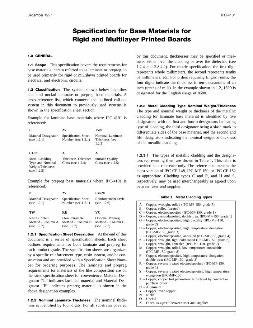
1.2.3 Metal Cladding Type Nominal Weight/Thickness
The type and nominal weight or thickness of the metallcladding for laminate base material is identified by fivdesignators, with the first and fourth designators indicatintype of cladding, the third designator being a slash markdifferentiate sides of the base material, and the second afifth designators indicating the nominal weight or thicknesof the metallic cladding.
1.2.3.1 The types of metallic cladding and the designators representing them are shown in Table 1. This tableprovided as a reference only. The referee document islatest version of IPC-CF-148, IPC-MF-150, or IPC-CF-15as appropriate. Cladding types C and R, and H andrespectively, may be used interchangeably as agreed ubetween user and supplier.
Table 1 Metal Cladding Types
A – Copper, wrought, rolled (IPC-MF-150, grade 5)B – Copper, rolled (treated)C – Copper, electrodeposited (IPC-MF-150, grade 1)D – Copper, electrodeposited, double treat (IPC-MF-150, grade 1)G – Copper, electrodeposited, high ductility (IPC-MF-150,
grade 2)H – Copper, electrodeposited, high temperature elongation
(IPC-MF-150, grade 3)J – Copper, electrodeposited, annealed (IPC-MF-150, grade 4)K – Copper, wrought, light cold rolled (IPC-MF-150, grade 6)L – Copper, wrought, annealed (IPC-MF-150, grade 7)M – Copper, wrought, rolled, low temperature annealable
(IPC-MF-150, grade 8)P – Copper, electrodeposited, high temperature elongation,
double treat (IPC-MF-150, grade 3)R – Copper, reverse treated electrodeposited (IPC-MF-150,
grade 1)S – Copper, reverse treated electrodeposited, high temperature
elongation (IPC-MF-150)T – Copper, copper foil parameters as dictated by contract or
purchase orderU – AluminumY – Copper invar copperN – NickelO – UncladX – Other, as agreed between user and supplier
1

dTheC
fien
yn
dthen
le
1
le
25
tioeiri
ofofdcs.stnhesttheasd asdonuser
ded)e
eess-cale,nd
nder-
ent
d
IPC-4101 December 1997
1.2.3.2 The weight or thickness of metallic cladding anthe designators representing them are listed in Table 2.table is provided as a reference only. The referee documis the latest version of IPC-CF-148, IPC-MF-150, or IPCF-152 as appropriate.
1.2.4 Thickness Tolerance (Laminate) The class ofthickness tolerance for laminate base material is identiby either A, B, C, D, K, L, M, or X as agreed upobetween user and supplier (see 3.8.4.2).
1.2.5 Surface Quality Class The class of surface qualitis identified by either A, B, C, D, or X as agreed upobetween user and supplier (see 3.8.3).
1.2.6 Reinforcement Style The reinforcement type anstyle of the prepreg is indicated by five digits based onchemical type and style. Typical examples of reinforcemdesignators are shown below:
a) ‘‘E7628’’ represents E glass reinforcement sty7628 per IPC-EG-140.
b) ‘‘S0313’’ represents S glass reinforcement style 3per IPC-SG-141.
c) ‘‘A3080’’ represents aramid reinforcement sty3080 per IPC-A-142.
d) ‘‘Q0525’’ represents quartz reinforcement style 5
per IPC-QF-143.
Reinforcement properties such as thickness, construcand weight are established in accordance with the rforcement style designations of the appropriate matespecification.
Table 2 Copper Foil Weight and Thickness
Foil Designator
Area Weight(g/m2)
NominalThickness(microns)
E (1/8)* 44.6 5.0
Q (1/4)* 80.3 9.0
T (3/8)* 107.0 12.0
H (1/2)* 153.0 17.2
M (3/4)* 229.0 25.7
1 305.0 34.3
2 610.0 68.6
3 916.0 103.0
4 1221.0 137.0
5 1526.0 172.0
6 1831.0 206.0
7 2136.0 240.0
10 3052.0 343.0
14 4273.0 480.0
* Values in parenthesis are common industry terminology,which may not be exact from metric origin.
2
isnt-
d
et
3
n,n-al
1.2.7 Prepreg Parameters A variety of test procedurescan be used to specify and determine fitness for useprepreg in multilayer board applications. The amountresin and how much that resin will flow under specifieconditions are the two critical performance characteristiThe specification for prepreg shall consist of one temethod from Column A and one test method from ColumB as shown below with the corresponding designators. Tuse of a test method from Column C is optional. If no temethod is chosen for Column C, zero-zero (00) shall bedesignator. The choice of the test methods shall beagreed upon between the user and supplier and suppliepart of the ordering information. The nominal value antolerances for the individual tests shall be as specifiedthe purchase order or by other agreement between theand supplier.
Column A Column B Column C
Resin ContentMethod
Flow Parameter Method Optional PrepregMethod
RC - % ResinContent
MF - % Resin Flow VC - VolatileContent
TW - TreatedWeight
SC - ScaledFlow
DY - DicyInspection
NF - No Flow GT - Gel Time
RE - Rheology Flow 00 - None Specified
PC - % Cure
DH - Delta H
1.2.8 Color Unless otherwise specified, all laminates anprepregs are supplied in the natural (undyed/unpigmentcolor. If another color is required by the user, it shall bspecified on the purchase order.
1.2.8.1 Contrast Agents Contrast agents, which may badded to a natural color resin system to enhance procing, such as tinting agents for contrast in automatic optiinspection, shall not adversely affect the performancproperties, or functionality of the laminate or prepreg ashall be considered as the natural color.
1.3 Dimensions and Tolerances All dimensions and tol-erances specified herein are applicable only to the eproduct. Dimensions are expressed in millimeters. Refence information is shown in parentheses.
2.0 APPLICABLE DOCUMENTS
The following documents of the issue in effect at the timof the order form a part of this specification to the extespecified herein.
2.1 IPC
IPC-T-50 Terms and Definitions for Interconnecting anPackaging Electronic Circuits

f
s
d
-
te
n
h-
t
d
t
t
r-
tor
e
f
-
of
n-
es
i-
t
-t
December 1997 IPC-4101
IPC-PC-90 General Requirements for Implementation oStatistical Process Control
IPC-CC-110 Guidelines for Selecting Core Constructionfor Multilayer Printed Wiring Board Applications
IPC-EG-140 Specification for Finished Fabric Woven from‘‘E’’ Glass for Printed Boards
IPC-SG-141 Specification for Finished Fabric Woven from‘‘S’’ Glass for Printed Boards
IPC-A-142 Specification for Finished Fabric Woven fromAramid for Printed Boards
IPC-QF-143 Specification for Finished Fabric Woven fromQuartz (Pure Fused Silica) for Printed Boards
IPC-CF-148 Resin Coated Metal for Printed Boards
IPC-MF-150 Metal Foil for Printed Wiring Applications
IPC-CF-152 Composite Metallic Materials Specificationfor Printed Wiring Boards
IPC-TM-650 Test Methods
2.1.5 Surface Examination, Unclad and Metal-ClaMaterial
2.1.9 Surface Scratch Examination Metal-Clad Foil
2.1.10 Visual Inspection for Undissolved Dicyandiamide
2.2.19.1 Length, Width and Perpendicularity of Laminaand Prepreg Panels
2.3.1.1 Chemical Cleaning of Metal-Clad Laminates
2.3.4.2 Chemical Resistance of Laminates, Prepreg aCoated Foil Products, by Solvent Exposure
2.3.4.3 Chemical Resistance of Core Materials to Metylene Chloride
2.3.6 Etching, Ammonium Persulfate Method
2.3.7 Etching, Ferric Chloride Method
2.3.7.1 Cupric Chloride Etching Method
2.3.10 Flammability of Laminate
2.3.16 Resin Content of Prepreg by Burn-Off
2.3.16.1 Resin Content of Prepreg by Treated Weight
2.3.16.2 Treated Weight of Prepreg
2.3.17 Resin Flow Percent of Prepreg
2.3.17.2 Resin Flow of ‘‘No Flow’’ Resin
2.3.18 Gel Time, Prepreg Materials
2.3.19 Volatile Content of Prepreg
2.4.4 Flexural Strength of Laminates (at AmbienTemperature)
d
2.4.4.1 Flexural Strength of Laminates (at ElevateTemperature)
2.4.8 Peel Strength of Metallic Clad Laminates
2.4.8.2 Peel Strength of Metallic Clad Laminates aElevated Temperature (Hot Fluid Method)
2.4.8.3 Peel Strength of Metallic Clad Laminates aElevated Temperature (Hot Air Method)
2.4.13.1 Thermal Stress of Laminates
2.4.22.1 Bow and Twist, Laminate
2.4.24 Glass Transition Temperature and Z-Axis Themal Expansion by TMA
2.4.25 Glass Transition Temperature and Cure Facby DSC
Note: Test Method 2.4.25 also describes thdelta glass transition temperature test (Delta Tg).
2.4.38 Prepreg Scaled Flow Testing
2.4.39 Dimensional Stability, Glass Reinforced ThinLaminates
2.4.41 Coefficient of Linear Thermal Expansion oElectrical Insulating Materials
2.4.41.1 Coefficient of Thermal Expansion by the Vitreous Silica (Quartz) Dilatometer Method
2.5.1 Arc Resistance of Printed Wiring Materials
2.5.5.2 Dielectric Constant and Dissipation FactorPrinted Wiring Board Materials - Clip Method
2.5.5.3 Permittivity (Dielectric Constant) and Loss Tagent (Dissipation Factor) of Materials (TwoFluid Cell Method)
2.5.6 Dielectric Strength of Rigid Printed WiringMaterial
2.5.6.2 Electric Strength of Printed Wiring Material
2.5.17.1 Volume and Surface Resistivity of DielectricMaterial
2.6.1 Fungus Resistance, Printed Wiring Materials
2.6.2.1 Water Absorption, Metal-Clad Plastic Laminat
2.6.16 Pressure Vessel Method for Glass Epoxy Lamnate Integrity
IPC-QL-653 Qualification of Facilities that Inspect/TesPrinted Boards, Components, and Materials
IPC-LQP-1730 Laminator’s Qualification Profile
J-STD-004 Requirements for Soldering Fluxes
J-STD-003 Solderability Test Methods For Printed WiringBoards
2.2 National Conference of Standards Laboratories
ANSI/NCSL Z540-1-1994 General Requirements for Calibration Laboratories and Measuring and Test Equipmen
3

r-
aroeenmblntelistirbinitis
ngr’supe-ioccnco
i-ysa
u
Pity
ual-n,i-totheion
or-for-of
oft ac-dat a3.
-lityed,an-
lthendard
-e
susnt.s, athe
istyer-Q,
itheci-all
IPC-4101 December 1997
2.3 International Standards
ISO 10012-1 Quality Assurance Requirements for Measuing Equipment, Part 1 - Metrological Confirmation Systemfor Measuring Equipment
3.0 REQUIREMENTS
3.1 Terms and Definitions The definition of terms shallbe in accordance with IPC-T-50 and the following.
3.1.1 Qualification Assessment Qualification Assess-ment is a form of risk reduction between a buyer andsource for laminates and prepregs. The laminator shall pduce an assessment of its capabilities and sources of vfication for the buyer to evaluate. The buyer must threview this assessment and determine whether the infortion and verification provided constitutes an acceptalevel of risk. The more verification of self declaratioparameters provided, the lower the risk factor associawith utilizing a new laminator. There is no minimum leveof Qualification Assessment Verification required by thstandard, and it is between the buyer and laminatordetermine the extent of verification applicable to therequirements. If the risk assessment is determined tounacceptably high, the risk may be reduced by increasthe verification requirements. The cost associated wreducing this risk varies with the type of verification thatdetermined to be necessary.
3.1.2 Quality Conformance Testing Quality conform-ance testing is performed on a regular basis followiqualification testing as determined by the ManufactureQuality System. This is done to demonstrate that the splier is continually meeting the finished product requirments of this specification and the applicable specificatsheet for each base material. In the absence of a domented Manufacturers Quality System, the conformantesting shall be conducted in accordance with the frequeas specified in Table 5 for laminates and Table 6 fprepregs.
3.1.3 Manufacturer’s Quality System The Manufactur-er’s Quality System is an organized entity within the lamnator’s operation that administers the documentation stem, steering committee, lines of responsibilities, etc.,described in IPC-PC-90.
3.1.4 Process Control Testing Testing performed forthe purpose of nominalizing the critical steps of the manfacturers internal process.
3.1.5 Self Declaration The first level of QualificationAssessment is Self Declaration. A completed IPC-LQ1730 contains a profile of a manufacturers site capabil
4
-ri-
a-e
d
o
egh
-
nu-eyr
-s
-
-,
processing and test equipment, technology specifics, qity program, manufacturing history, company informatioand data verification sources. Self Declaration is the lamnator’s view of its products and process capabilitiesmeet the customer’s requirements, the requirements ofstandard, and the applicable associated specificatsheet(s) (see 3.3).
3.1.6 Quality Assessment Data The data contained inthe Self Assessment is compiled and analyzed for perfmance characteristics of laminates or prepregs. The permance data may be based on information from a varietyboth internal and external sources.
3.1.7 Sample Qualification Verification by SampleQualification signifies that a manufacturer was capableproducing a product with a given set of parameters apoint in time when the Qualification sample was manufatured. Sample Qualification Testing of laminate anprepreg performance characteristics shall be performedfacility that has demonstrated compliance of IPC-QL-65
3.1.8 Production Data Production data is normal performance data from manufacturing runs generated as a quaassurance function. This data can be compiled, analyzand reported as support for product compliance to this stdard by the laminator.
3.1.9 Customer Test Data Customer test data is normaperformance data generated at incoming inspection bycustomer. This data can be compiled, analyzed, areported as support for product compliance to this standby the laminator.
3.1.10 Internal Assessment Internal Assessments consist of periodic supplier verification of data contained in thQuality Profile section of the Self Declaration.
3.1.11 Individual Customer Audit The Individual Cus-tomer Audit is an evaluation of the laminator’s facility tocompare the current Management Quality System verthe Self Declaration and the requirements of this documeThe analysis, summary, and necessary corrective actionthe discretion of the customer, may become part of tlaminator’s Self Declaration.
3.1.12 Independent Third Party Assessment Assess-ments are performed by a third party assessor, whichgenerally procedural in nature. Examples of third parassessors are ISO Registrars, Malcom Baldridge, Undwriters’ Laboratories, Canadian Standards Agency, IECDSCC, etc.
3.2 Specification Sheets The individual item require-ments shall be as specified herein and in accordance wthe applicable specification sheets. Where there is no spfication sheet available, the individual requirements sh

aenonov
ablengei-
eli-fopantior’sle
idk-ni-i-
to-
t-eannarty
nc
2,
nateire-lier.
0,teds,and
eca-neredpon
le ifinon/Kss4.ntsd,ire-.1offorasepli-
ty,as
e a
e a
gthor
December 1997 IPC-4101
be as specified in complimentary documents such as mter drawings or ordering data sheets (see 6.1). In the evof any conflict between requirements of this specificatisheet and a complimentary document, the latter shall gern.
3.3 Manufacturers Quality Profile Suppliers of lami-nates and prepregs shall assess their manufacturing capity and complete the Manufacturer’s Qualification ProfiIPC-LQP-1730. A detailed Qualification Assessment listiof the participating laminators is kept by the IPC in thform of IPC-LQP-1730 and is available either electroncally or in hard copy.
3.4 Qualification Testing Laminate and prepreg basmaterials furnished under this specification shall be quafied as described in Table 5 for laminates and Table 6prepregs. The supplier shall retain on file data, which suports that the material meets the requirements of this stdard using the test methods described herein. Qualificatesting shall be performed to demonstrate the supplieability to meet all of the requirements of each applicabspecification sheet for each base material.
3.4.1 Qualification Testing Laminate Qualification oflaminates shall require test data for both thin and rigmaterials. One set of test information for a laminate thicness≤0.25 mm shall qualify the manufacturer for thilaminate materials. One set of test information for a lamnate≥0.8 mm shall qualify the manufacturer for rigid lamnate materials.
3.4.2 Qualification Testing Prepreg Qualification of theprepreg comprised of thinnest reinforcement style aumatically qualifies by extension all the thicker reinforcement styles for a given specification sheet.
3.5 Verification of Manufacturer’s Quality System Theverification of the Manufacturer’s Quality System, as oulined in the Self Declaration in IPC-LQP-1730, may bconducted to reduce risk to the buyer. The verification cbe accomplished via several methods, including InterAssessment, Individual Customer Audit, and/or Third PaAssessment.
3.6 Conflict In the event of conflict, the following orderof precedence shall apply:
1. Purchase order
2. Master drawing (see 6.1.1-D or 6.1.2-D)
3. This specification (specification sheets take precedeover body of text)
4. Applicable documents (see 2.0)
3.7 Materials
3.7.1 Metal Cladding Metal cladding shall meet therequirements of IPC-MF-150, IPC-CF-148, IPC-CF-15
s-t
-
il-
r--n
-
l
e
or as agreed upon between user and supplier. For altermetal claddings not covered by industry standards, requments shall be as agreed upon between user and supp
3.7.2 Reinforcement Fabric Construction of the rein-forcement fabrics shall be in accordance with IPC-EG-14IPC-SG-141, IPC-A-142, and IPC-QF-143. For alternareinforcement types not covered by industry standarrequirements shall be as agreed upon between usersupplier.
3.7.3 Resin Systems Resin systems used to produclaminate and prepreg base materials under this specifition shall be as specified in the individual specificatiosheets (see 1.2.1). For alternate resin systems not covby industry standards, requirements shall be as agreed ubetween user and supplier.
3.8 General Requirements/Acceptability Laminate orprepreg base materials shall be considered acceptabthey meet the minimum requirements listed below andthe applicable specification sheet, or as agreed upbetween user and supplier. Unless otherwise specified, Aproperty requirements shall be in effect for Table 7. Unleotherwise specified, Grade A shall be in effect for TableUnless otherwise specified, Class A property requiremeshall be in effect for 3.8.3.1.1. Unless otherwise specifiethe range tolerance shall be Range B for 3.9.1.2. Requments only apply to the working area defined in 3.8.1through 3.8.1.4, unless otherwise specified. Both sidesdouble-sided laminate base material shall be evaluatedthose requirements that are impacted by the metal/bmaterial relationships. See specific test methods for apcability.
Note: When tests are performed by the procuring activiprepreg should be properly stored and should be testedsoon as possible after receipt (not to exceed 5 days).
3.8.1 Fabricated Sheets and Panels
3.8.1.1 Fabricated Laminate Sheet Material A fabri-cated sheet shall be any size≥0.55 m2. The working areaof a fabricated sheet is considered to be the area insid25 mm border around the perimeter of the sheet.
3.8.1.2 Fabricated Laminate Panel Material A fabri-cated panel shall be any size <0.55 m2. The working areaof a fabricated panel is considered to be the area insid13 mm border around the perimeter of the panel.
3.8.1.3 Fabricated Prepreg Panels Fabricated panelsare cut-to-size pieces of prepreg that are nominally (lentimes width, excluding considerations of tooling holesother cut-outs) <0.55 m2. The working border shall be thearea excluding a 15 ± 3 mmborder.
5
esse
esoben
teiv
roe-thth
dreus
n-esre
ic
eshamnm
haell0
.5intr-vi-
ora-thtsss
il
0so
n
of
ilr).lh.o
IPC-4101 December 1997
3.8.1.4 Fabricated Prepreg Rolls Prepreg rolls are con-tinuous lengths of prepreg that are rolled for the purposof inventory and custom fabrication by the user. Only ClaA is applicable, in which the working area shall be thprepreg, excluding the outer 25 ± 5 mmedge.
No more than 5% of the nominal roll length shall bunsuitable for panel fabrication, which includes spliceareas sampled for testing, and non-splice breaks in the ctinuous length of the prepreg. The length of the roll maycompensated to replace that prepreg unsuitable for pafabrication as agreed upon between user and supplier.
3.8.2 Inspection Lot
3.8.2.1 Inspection Lot Laminate An inspection lot shallmeet the following criteria:
a.) Material covered by a single specification sheet.
b.) One press load or 200 sheets, whichever is greaThe 200 sheets must be comprised of consecutpress loads of the same specification sheet.
3.8.2.2 Inspection Lot Prepreg An inspection lot ofprepreg shall be one master roll of reinforcement as pvided by the supplier. Splices provided by the reinforcment supplier are not considered to be a change inmaster roll. Each master roll shall be inspected atbeginning and at the end as a minimum.
3.8.2.3 Preparation of Samples Unless otherwise speci-fied herein, samples and test specimens shall be prepareaccordance with standard in-house procedures. If a refemethod is required, it shall be as agreed upon betweenand supplier.
3.8.2.4 Etching Process and Etchant Removal for Cop-
per Foil Specimens Unless otherwise specified, any stadard procedure may be used. However, IPC-TM-650, TMethods 2.3.6, 2.3.7, or 2.3.7.1 shall be used as a refe
3.8.2.5 Standard Laboratory Conditions Unless other-wise specified herein, all inspections shall be performedaccordance with the test and laboratory conditions spefied in IPC-QL-653.
3.8.3 Visual Properties
3.8.3.1 Laminate Visual Properties The specimen shallbe tested in accordance with Table 5 for laminates. Unlotherwise specified, the working area of the specimen sbe examined with normal 20/20 vision. The worst 50 mx 50 mm area shall be examined at 10X magnificatioVisual inspection may be carried out under ambient teperature and humidity conditions.
6
s
,n-
el
r.e
-
ee
ineer
te.
ni-
sll
.-
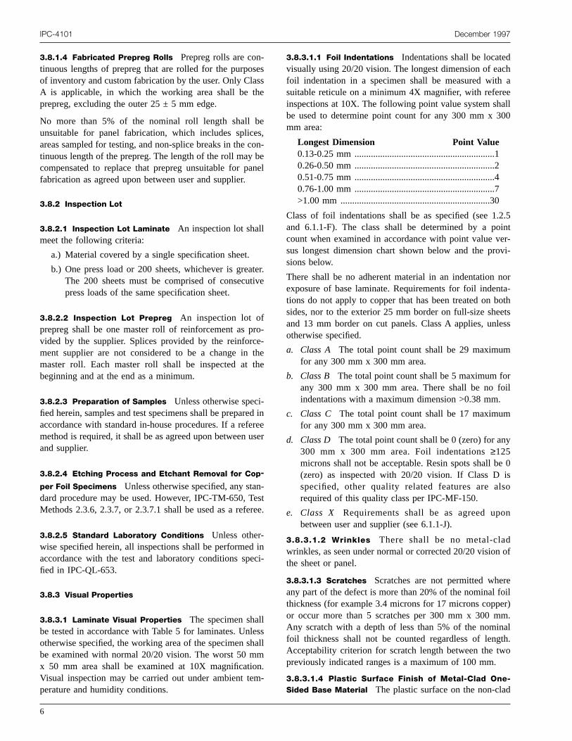
3.8.3.1.1 Foil Indentations Indentations shall be locatedvisually using 20/20 vision. The longest dimension of eacfoil indentation in a specimen shall be measured withsuitable reticule on a minimum 4X magnifier, with refereinspections at 10X. The following point value system shabe used to determine point count for any 300 mm x 30mm area:
Longest Dimension Point Value0.13-0.25 mm ............................................................10.26-0.50 mm ............................................................20.51-0.75 mm ............................................................40.76-1.00 mm ............................................................7>1.00 mm ................................................................30
Class of foil indentations shall be as specified (see 1.2and 6.1.1-F). The class shall be determined by a pocount when examined in accordance with point value vesus longest dimension chart shown below and the prosions below.
There shall be no adherent material in an indentation nexposure of base laminate. Requirements for foil indenttions do not apply to copper that has been treated on bosides, nor to the exterior 25 mm border on full-size sheeand 13 mm border on cut panels. Class A applies, unleotherwise specified.
a. Class A The total point count shall be 29 maximumfor any 300 mm x 300 mm area.
b. Class B The total point count shall be 5 maximum forany 300 mm x 300 mm area. There shall be no foindentations with a maximum dimension >0.38 mm.
c. Class C The total point count shall be 17 maximumfor any 300 mm x 300 mm area.
d. Class D The total point count shall be 0 (zero) for any300 mm x 300 mm area. Foil indentations≥125microns shall not be acceptable. Resin spots shall be(zero) as inspected with 20/20 vision. If Class D ispecified, other quality related features are alsrequired of this quality class per IPC-MF-150.
e. Class X Requirements shall be as agreed upobetween user and supplier (see 6.1.1-J).
3.8.3.1.2 Wrinkles There shall be no metal-cladwrinkles, as seen under normal or corrected 20/20 visionthe sheet or panel.
3.8.3.1.3 Scratches Scratches are not permitted whereany part of the defect is more than 20% of the nominal fothickness (for example 3.4 microns for 17 microns coppeor occur more than 5 scratches per 300 mm x 300 mmAny scratch with a depth of less than 5% of the nominafoil thickness shall not be counted regardless of lengtAcceptability criterion for scratch length between the twpreviously indicated ranges is a maximum of 100 mm.
3.8.3.1.4 Plastic Surface Finish of Metal-Clad One-Sided Base Material The plastic surface on the non-clad

ino
),ng
ureicanatea
tes)th
tasm
o
m
hellenoa
ds
re
ic
oe
re
e-
n-
m
t
ip-is
e
.45enfici-bees,rnen-
re-snier.5
December 1997 IPC-4101
side of base materials shall be as produced by the curprocess. There should be no evidence of resin-starvedscorched areas.
3.8.3.1.5 Surface Finish of Foil after Curing Except for
Double Treat Unless otherwise specified (see 6.1.1-Jdiscoloration of the copper surface as a result of the curiprocess shall be acceptable.
3.8.3.1.6 Surface and Subsurface Imperfections Theetched panels shall be inspected to verify that no subsface imperfections in excess of those shown below apresent. The panels shall be inspected using an optapparatus or aid which provides a minimum magnificatioof 4X. Referee magnification shall be accomplished10X. Lighting conditions of inspection shall be appropriatto the type, grade and thickness being inspected oragreed between user and supplier.
Surface and subsurface imperfections (such as weaveture, resin saturation, scorching, voids, foreign inclusionshall be acceptable provided the imperfections meetfollowing:
a. The reinforcement fiber is not cut or exposed.
b. There is not more than one piece of residual meper 0.5 m2 of surface examined and this piece doenot have an area greater than that of circle 0.125 m(0.0124 mm2) in diameter.
c. The imperfections do not propagate as a resultthermal stress.
d. The foreign inclusions are translucent.
e. Opaque foreign fibers are≤13 mm in length andaverage no more than 1.0 per 300 mm x 300 marea inspected.
f. Opaque foreign other than fibers shall not exceed t0.50 mm. Opaque foreign inclusions <0.13 mm shanot be counted. Opaque foreign inclusions betwe0.50 mm and 0.13 mm inclusive shall average nmore than two spots per 300 mm x 300 mm areinspected.
g. Voids are≤0.075 mm in the longest dimension ando not occur in void clusters any more than 3 voidin a 3.2 mm circle.
3.8.3.2 Prepreg Visual Properties The specimen shallbe tested in accordance with Table 6 for prepregs. Prepvisual inspection is conducted with normal 20/20 vision.
3.8.3.2.1 Inclusions Metallic inclusions are not accept-able. Inclusions or foreign material that are nonmetallshall be acceptable, provided they are≤0.50 mm in thelongest dimension and occur no more frequently than twper 300 mm x 300 mm of surface for the panel sizinspected or a 610 mm x width sample.
gr
r-
l
s
x-
e
l
f
g
3.8.3.2.2 Impregnation Imperfections Imperfections inimpregnation shall be acceptable provided the criteria amet as shown below.
a. Overall prepreg thickness increases from reinforcment imperfections is 99% maximum.
b. Dewetted areas (measured in at least two dimesions) are 2.3 mm maximum.
c. Pin-holed areas are 0.65 mm maximum.
d. Reinforcement distortion (variation in pick line) per300 mm distance is 25 mm maximum.
e. Creases with exposed reinforcement are <15 mmaximum.
f. Silver streaks, cigar voids (nonwetted fibers) are nopresent.
g. Brown streaks (binder marks) are not present.
3.8.4 Dimensional Length, width, thickness, and otherdimensional characteristics shall be measured with equment capable of accuracy to verify the requirements of thspecification.
3.8.4.1 Length and Width When tested in accordancewith Tables 5 or 6 as applicable, the material shall meet thlength and width requirements specified below.
3.8.4.1.1 Length and Width Laminate For laminate basematerials, the manufacturer’s standard sizes between 0and 3.6 m in length and 0.45 and 1.5 m in width shall bacceptable. The length and width may vary no more tha25 mm over or under the standard size. Unless specidimensions are specified, standard size metal-clad lamnates from which test specimens have been cut shallacceptable. When smaller sizes are cut from standard sizthe permissible variations from the specified length owidth shall be as specified in Table 3, or as agreed upobetween user and supplier. Adjacent edges must be perpdicular within 0.075 mm per 25 mm for laminate.
3.8.4.1.2 Length and Width Prepreg The length andwidth of prepreg sheets shall be as specified in the procument document (see 6.1.2-H). The permissible variationfrom the specified length or width shall be as specified iTable 4, or as agreed upon between user and supplAdjacent edges shall be perpendicular with 0.13 mm per 2mm.
Table 3 Permissible Variationin Length and Width of Laminates
Panel Size Sheet Size
<300 mm 300 to 600 mm >600 mm +25.0 mm-0.0 mm± 0.80 mm ± 1.60 mm ± 3.2 mm
7

eia
seee
IPC-4101 December 1997
3.8.4.1.3 Prepreg Roll Width For prepreg base materialsthe width of the rolls shall be as specified in the procurment document (see 6.1.2-H). The width of the matershall be within +6.4/-0.0 mm of the specified value.
3.8.4.1.4 Prepreg Roll Length The length of the prepregrolls shall be as specified in the procurement document (6.1.2-H). The length shall be within ± 1% of the valuspecified.
8
-l
Table 4 Permissible Variationin Length and Width of Prepregs
Panel Size
<300 mm 300 to 600 mm >600 mm
Grade A 1.6 mm 3.2 mm 6.4 mm
Grade B 0.8 mm 1.6 mm 3.2 mm
Table 5 Reference Information and Test Frequency of Laminate
This table is applicable for Qualification Testing and where a documented Manufacturers Quality System is absent for ConformanceTesting.
TestsRequirementParagraph
Test1
MethodQualification
TestingConformance
Testing FrequencySamplesper Sheet
General
Visuals 3.8.3.1 2.1.5 U U Audit2
Surface Finishes 3.8.3.1.13.8.3.1.5
2.1.52.1.9
U Audit2
Surface/Sub-SurfaceImperfections
3.8.3.1.6 U U Lot 3
Dimensional9 3.8.4 2.2.19.1 U U Audit2 -
Bow/Twist 3.8.4.3 2.4.22.1 U U Lot 1
Physical
Peel StrengthAfter Thermal Stress
3.9.1.1.1 2.4.8 U U Lot 45
Peel StrengthAt Elevated Temperature4
3.9.1.1.2 2.4.82.4.8.22.4.8.3
U U 3 Mon 45
Peel StrengthAfter/Exposure to3,4
Process Solutions
3.9.1.1.3 2.4.8 U U 3 Mon 45
Dimensional Stability12 3.9.1.2 2.4.39 U U 1 Mon 3
Flexural Strength 3.9.1.3 2.4.4 U U 12 Mon. 67
Flexural Strengthat Elevated Temperatures4
3.9.1.4 2.4.4.1 U U 3 Mon. 38
Chemical
Flammability10 3.10.1.1 2.3.10 U U 1 Mon. 3
Thermal Stress Etched 3.10.1.2 2.4.13.1 U U Lot 2
Thermal Stress Unetched 3.10.1.2 2.4.13.1 U U Lot 2
Solderability 3.10.1.3 J STD-003Edge Dip
U U 3 Mon 3
Chemical Resistance3 3.10.1.4 2.3.4.3 U U Lot 1
Metal Surface Cleanability3 3.10.1.5 2.3.1.1 U U Lot 1
Tg3 3.10.1.6 2.4.24
2.4.25U U Lot 1
Delta Tg3 3.10.1.7 2.4.25 U Lot 1
Ave. X/Y CTE3 3.10.1.8 2.4.412.4.41.1
U Lot 1
Electrical
Permittivity4 3.11.1.1 2.5.5.2,2.5.5.3
U U 1 Mon 3
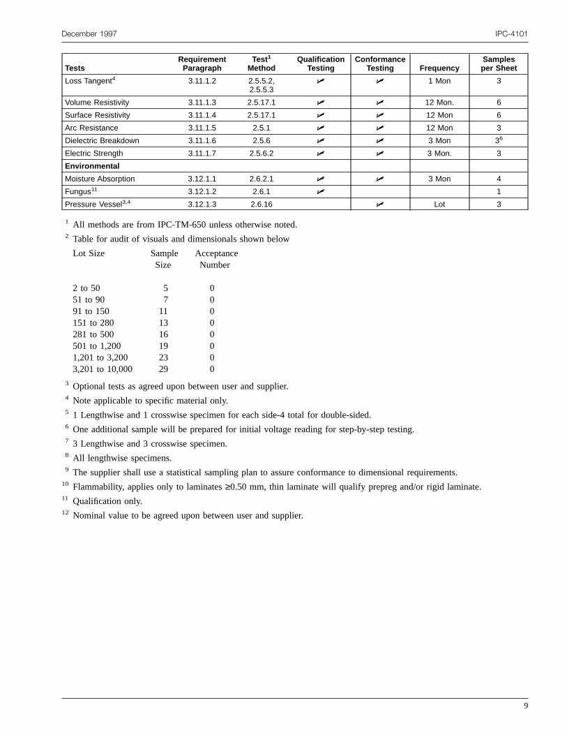
December 1997 IPC-4101
TestsRequirementParagraph
Test1
MethodQualification
TestingConformance
Testing FrequencySamplesper Sheet
Loss Tangent4 3.11.1.2 2.5.5.2,2.5.5.3
U U 1 Mon 3
Volume Resistivity 3.11.1.3 2.5.17.1 U U 12 Mon. 6
Surface Resistivity 3.11.1.4 2.5.17.1 U U 12 Mon 6
Arc Resistance 3.11.1.5 2.5.1 U U 12 Mon 3
Dielectric Breakdown 3.11.1.6 2.5.6 U U 3 Mon 36
Electric Strength 3.11.1.7 2.5.6.2 U U 3 Mon. 3
Environmental
Moisture Absorption 3.12.1.1 2.6.2.1 U U 3 Mon 4
Fungus11 3.12.1.2 2.6.1 U 1
Pressure Vessel3,4 3.12.1.3 2.6.16 U Lot 3
1 All methods are from IPC-TM-650 unless otherwise noted.2 Table for audit of visuals and dimensionals shown below
Lot Size
2 to 5051 to 9091 to 150151 to 280281 to 500501 to 1,2001,201 to 3,2003,201 to 10,000
SampleSize
57111316192329
AcceptanceNumber
00000000
3 Optional tests as agreed upon between user and supplier.4 Note applicable to specific material only.5 1 Lengthwise and 1 crosswise specimen for each side-4 total for double-sided.6 One additional sample will be prepared for initial voltage reading for step-by-step testing.7 3 Lengthwise and 3 crosswise specimen.8 All lengthwise specimens.9 The supplier shall use a statistical sampling plan to assure conformance to dimensional requirements.10 Flammability, applies only to laminates≥0.50 mm, thin laminate will qualify prepreg and/or rigid laminate.11 Qualification only.12 Nominal value to be agreed upon between user and supplier.
9

form-
ed for
IPC-4101 December 1997
Table 6 Reference Information and Test Frequency of Prepreg
This table is applicable for Qualification Testing and where a documented Manufacturers Quality System is absent for ConformanceTesting.
TestsRequirementParagraph
Test1
MethodQualification
TestingConformance
Testing FrequencySamplesper Sheet
General
Visuals 3.8.3.2 2.1.5 U U Lot 1
Dimensions 3.8.4 U U Audit6
Physical
Resin Content Method2 3.9.2.1
Resin Content Percent
By Treated Weight2 3.9.2.1.1 2.3.16.1 U Lot 1
By Burn-Off2 3.9.2.1.2 2.3.16 U U Lot 1
Treated Weight Total2 3.9.2.1.3 2.3.16.2 U Lot
Flow Parameter Method3 3.9.2.2
Resin Flow Percent3 3.9.2.2.1 2.3.17 U U Lot 1
Scaled Flow Thickness3 3.9.2.2.2 2.4.38 U U Lot 1
No Flow 3.9.2.2.3 AABUS7 U U Lot 1
Rheological Flow 3.9.2.2.4 AABUS7 U Lot 1
Delta H 3.9.2.2.5 AABUS7 U Lot 1
Gel Time4 3.9.2.2.6 2.3.18 U U Lot 1
% Cure 3.9.2.2.7 AABUS7 U Lot 1
Volatile Content4 3.9.2.2.8 2.3.19 U U Lot 1
Chemical
Flammability8,9 3.10.2.1 2.3.10 U U 1 Mon 3
Chemical Resistance4,9 3.10.2.2 2.3.4.2 U Lot
Presence of Dicy4 3.10.2.3 2.1.10 U U Lot
Electrical
Permittivity5,9 3.11.2.1 2.5.5.22.5.5.3
U 1 Mon 3
Loss Tangent5,9 3.11.2.2 2.5.5.22.5.5.3
U 1 Mon 3
Electric Strength9 3.11.2.3 2.5.6.2 U U 3 Mon 3
Environmental
Fungus9,10 3.12.2.1 2.6.1 U 1
1 All methods are from IPC-TM-650 unless otherwise noted.2 For qualification purposes, Resin Content shall be in accordance with Resin Content Percent by Burn Off. For conance testing, Resin Content may be determined using IPC-TM-650, Test Methods 2.3.16, 2.3.16.1, or 2.3.16.2.
3 For prepreg types other than No Flow Prepreg, either Resin Flow percent or Scaled Flow Thickness may be specifiqualification and conformance testing.
4 Optional tests are agreed upon between user and supplier.5 Note applicable to specific material only.6 Supplier shall use a statistical sampling plan to assure conformance to dimensional specifications.7 AABUS = As Agreed Upon Between User and Supplier.8 Flammability, thin laminate will qualify Prepreg and/or Rigid Laminate.9 Test to be conducted after pressing the prepreg into a laminate.10 Qualification only.
10

e
o
ns
).
i-a
in
rk-liede
iblere-aof
malar-hear
nelcut
December 1997 IPC-4101
3.8.4.2 Thickness
3.8.4.2.1 Thickness Class A, B, and C Laminate Materi-als For Class A, B, and C materials, the thickness of thlaminate base material without the metal cladding shall bmeasured with a micrometer (see Figure 1).
3.8.4.2.2 Thickness Class D Laminate Materials ForClass D materials, thickness shall be determined by micrsection in accordance with Table 5. Three microsectionshall be done on each specimen. Each microsection shalllocated at independent corners of the specimen andcloser than 2.54 cm from any edge. The base thickneshall be measured in accordance with Figure 1 and takenthe closest point between metal claddings (see Figure 1
3.8.4.2.3 Thickness Class K, L, M Laminate MaterialsFor class K, L, and M materials, the thickness of the lamnate with the metal cladding shall be measured withmicrometer (see Figure 1).
3.8.4.2.4 Thickness Tolerance Laminate Materials Thethickness of the laminate with the working area shall be
e
-sbeosat
accordance with Table 7. The thickness outside the woing area of the laminate sheet or cut-to-size panel suppby the supplier shall not vary from the nominal by a valu>125% of the specified tolerance.
3.8.4.3 Bow and Twist Laminate Materials When speci-mens are tested in accordance with Table 5, permissbow and twist shall be as defined in Table 8. This requiment does not apply to double-sided laminate withdielectric thickness <0.50 mm or with unequal cladding≥0.065 mm thickness between the two sides.
3.8.4.3.1 Sheets and Panels with Both Dimensions≥300 mm Fabricate a 300 mm x 300 mm specimen froa sheet or panel in a manner that will not impart additionbow or twist to the specimen. (For example, when sheing, test specimen sheared edges shall be those on the sdeck side of each cut.)
3.8.4.3.2 Panels with One or Both Dimensions <300 mmIf both dimensions are <300 mm, use an as-received paas the test specimen. If one dimension is >300 mm,back to 300 mm.
IPC-4101-1
Figure 1 Thickness Tolerance For Class D Materials
11

IPC-4101 December 1997
Table 7 Thickness and Tolerances for Laminates
Nominal Thicknessof Laminate Class A/K Class B/L Class C/M Class D
0.025 to 0.119 mm ± 0.025 mm ± 0.018 mm ± 0.013 mm -0.013 + 0.025 mm
0.120 to 0.164 mm ± 0.038 mm ± 0.025 mm ± 0.018 mm -0.018 + 0.030 mm
0.165 to 0.299 mm ± 0.050 mm ± 0.038 mm ± 0.025 mm -0.025 + 0.038 mm
0.300 to 0.499 mm ± 0.064 mm ± 0.050 mm ± 0.038 mm -0.038 + 0.051 mm
0.500 to 0.785 mm ± 0.075 mm ± 0.064 mm ± 0.050 mm -0.051 + 0.064 mm
0.786 to 1.039 mm ± 0.165 mm ± 0.10 mm ± 0.075 mm Not applicable
1.040 to 1.674 mm ± 0.190 mm ± 0.13 mm ± 0.075 mm Not applicable
1.675 to 2.564 mm ± 0.23 mm ± 0.18 mm ± 0.10 mm Not applicable
2.565 to 3.579 mm ± 0.030 mm ± 0.23 mm ± 0.14 mm Not applicable
3.580 to 6.35 mm ± 0.56 mm ± 0.30 mm ± 0.15 mm Not applicable
ne.3n
ee.
ina
thb
itesca
alor.edthe
r.
ininalon
lyner-reet.
n-
theheenestt
3.9 Physical Requirements
3.9.1 Physical Requirements Laminate Materials
3.9.1.1 Peel Strength When specimens are tested iaccordance with Table 5, peel strength for all copper typshall meet the requirements of 3.9.1.1.1 through 3.9.1.1For non-copper metallic foils, adhesion test methods avalues shall be as agreed upon by user and supplier.
All foil weights may be plated up to 35 microns and thpeel strength inspected using the original specified valu
3.9.1.1.1 Peel Strength after Thermal Stress Whenspecimens are tested in accordance with Table 5, the mmum average peel strength following thermal stress shbe as indicated in the applicable specification sheet.
3.9.1.1.2 Peel Strength at Elevated TemperatureWhen specimens are tested in accordance with Table 5,specimens shall meet the requirements of the applicaspecification sheet.
3.9.1.1.3 Peel Strength after Process Chemicals(Optional) When specimens are tested in accordance wTable 5, the minimum average peel strength after procchemicals shall be as indicated in the applicable specifition sheet.
Table 8 Bow and Twist, mm per 30.5 cm
0.5-0.78 mmSingle sided≤200 mmSingle sided >200 mm - 300 mmDouble sided≤200 mmDouble sided >200 mm - 300 mm
6.06.03.04.5
0.79-1.67 mmSingle sided≤200 mmSingle sided >200 mm - 300 mmDouble sided≤200 mmDouble sided >200 mm - 300 mm
4.54.51.53.0
>1.68 mmSingle sided≤200 mmSingle sided >200 mm - 300 mmDouble sided≤200 mmDouble sided >200 mm - 300 mm
4.54.51.53.0
12
s.d
i-ll
ele
hs-
3.9.1.2 Dimensional Stability When specimens aretested in accordance with Table 5, the nominal dimensionstability shall be as agreed upon between user and vendThe tolerance shall be Range B unless otherwise specifion the purchase order or by other agreement betweenuser and vendor:
RANGE A ± 3.0 microns per cm.RANGE B ± 5.0 microns per cm.RANGE C ± 7.5 microns per cm.RANGE X Unspecified, not Applicable, or as
agreed upon between user and supplie
3.9.1.3 Flexural Strength The metal cladding of thespecimens shall be completely removed by etchingaccordance with 3.8.2.4. When specimens are testedaccordance with Table 5, the average minimum flexurstrength shall be as indicated in the applicable specificatisheet.
3.9.1.4 Flexural Strength at Elevated Temperature Themetal cladding of the specimens shall be completeremoved by etching in accordance with 3.8.2.4. Whespecimens are tested in accordance with Table 5, the avage minimum flexural strength at elevated temperatushall be as indicated in the applicable specification she
3.9.2 Physical Requirements Prepreg Materials
3.9.2.1 Resin Content Method The quantity of resin ona particular reinforcement shall be specified by resin cotent or treated weight total.
3.9.2.1.1 Resin Content Percent (by Treated Weight)When specimens are tested in accordance with Table 6,percentage of resin content shall be as indicated on tapplicable specification sheet or as agreed upon betweuser and supplier. In the case of dispute, the referee tmethod will be in accordance with IPC-TM-650, TesMethod 2.3.16 (see 3.9.2.1.2).

epls
hdiee
cilie
e,ta
weenion
lycui-ifili
mnnonee
dwnr.
r-aee
megelnreed
intol-ent,
tiletheeen
indi-the
innog.
snottoenso-o-at
halland
ainon
hallreed
, theuser
December 1997 IPC-4101
3.9.2.1.2 Resin Content Percent (by Burn-off) Whenspecimens are tested in accordance with Table 6, the pcentage of resin content shall be as indicated on the apcable specification sheet, or as agreed upon between uand supplier.
3.9.2.1.3 Treated Weight Total When specimens aretested in accordance with Table 6, the total treated weigof the resin and reinforcement combined shall be as incated on the applicable specification sheet, or as agrupon between user and supplier.
3.9.2.1.4 Variation Within a Panel Resin content varia-tion is no greater than that specified in the applicable spefication sheet, or as agreed upon between user and supp
3.9.2.2 Flow Parameter Method The amount that theresin will flow under certain controlled conditions shall bspecified by resin flow(MF), scaled flow(SC), no flow(NF)rheological properties(RE), delta H(DH), or percencure(PC) as indicated on the procurement document, oragreed upon between user and supplier.
3.9.2.2.1 Resin Flow Percent When specimens aretested in accordance with Table 6, the nominal resin flopercent shall be as indicated on the procurement documand the tolerance of the resin flow percent measuremshall meet the requirements of the applicable specificatsheet, or as agreed upon between user and supplier.
3.9.2.2.2 Scaled Flow Thickness When specimens aretested in accordance with Table 6, the nominal per pthickness shall be as indicated on the procurement doment. The per ply thickness shall not vary from the nomnal thickness more than specified on the applicable speccation, sheet or as agreed upon between user and supp
3.9.2.2.3 Resin Flow for No Flow Type Prepreg Whenspecimens are tested in accordance with Table 6, the nonal resin flow percent or no flow shall be as indicated othe procurement document. The resin flow percent orflow shall not vary from the nominal value more thaspecified on the applicable specification sheet, or as agrupon between user and supplier.
3.9.2.2.4 Rheological Flow When specimens are testein accordance with Table 6, the nominal rheological floand tolerance shall be as indicated in the procuremedocument, or as agreed upon between user and supplie
3.9.2.2.5 Delta H When specimens are tested in accodance with Table 6, the nominal delta H and tolerance shbe as indicated in the procurement document, or as agrupon between user and supplier.
r-i-er
t-d
-r.
s
ntt
-
-er.
i-
d
t
lld
3.9.2.2.6 Gel Time (Optional Test) When specimens aretested in accordance with Table 6, the nominal gel tishall be as indicated on the procurement document. Thetime shall not vary from the nominal gel time more thaspecified on the applicable specification sheet, or as agupon between user and supplier.
3.9.2.2.7 Cure Percent When specimens are testedaccordance with Table 6, the nominal cure percent anderance shall be as indicated in the procurement documor as agreed upon between user and supplier.
3.9.2.2.8 Volatile Content (Optional Test) When speci-mens are tested in accordance with Table 6, the volacontent shall not exceed the maximum as indicated onapplicable specification sheet, or as agreed upon betwuser and supplier.
3.10 Chemical Requirements
3.10.1 Chemical Requirements Laminate Materials
3.10.1.1 Flammability When specimens are testedaccordance with Table 5, the maximum average and invidual observed burn times shall be as indicated inapplicable specification sheet.
3.10.1.2 Thermal Stress When specimens are testedaccordance with Table 5, the specimens shall exhibitevidence of blistering, delamination, wrinkling or crackin
3.10.1.3 Solderability When laminates are tested aspecified in Table 5, the metal-clad surfaces shallexhibit nonwetting or more than 5% dewetting. Priortesting, specimens shall be cleaned as follows: Specim75 mm x 75 mm shall be cut, wiped with isopropyl alchol, and immersed in a 20% by volume solution of hydrchloric acid, technical grade, 5.6°C Baume , maintained21 ± 5°C for a period of 15 seconds. The specimens sbe rinsed with a cold water spray rinse for 5 secondsblown dry with filtered, oil free, compressed air.
3.10.1.4 Chemical Resistance (Optional) When speci-mens are tested in accordance with Table 5, the weight gfollowing chemical exposure shall be as agreed upbetween the user and supplier.
3.10.1.5 Metal Surfaces Cleanabilty When specimensare tested in accordance with Table 5, the material smeet the metal surfaces cleanability requirements as agupon between the user and supplier.
3.10.1.6 Glass Transition Temperature (Optional)When specimens are tested in accordance with Table 5Tg shall meet the values as agreed upon between theand supplier.
13

ithon
ithon
egeinmi
aion
thpo
ntiv-on
nanion
div-on
div-on
asaar
ins-n
n.
as
m
c-
-
fi-
h
thei-di-
edup-
st
IPC-4101 December 1997
3.10.1.7 Delta Glass Transition Temperature(Optional) When specimens are tested in accordance wTable 5, the delta Tg shall meet the values as agreed upbetween the user and supplier.
3.10.1.8 Average Coefficient of Thermal Expansion(Optional) When specimens are tested in accordance wTable 5, the X/Y CTE shall meet the values as agreed upbetween the user and supplier.
3.10.2 Chemical Requirements Prepreg Materials
3.10.2.1 Flammability When laminated specimens artested in accordance with Table 6, the maximum averaand individual observed burn times shall be as indicatedthe applicable specification sheet. Prepreg must be lanated to produce a minimum thickness of 0.50 mm.
3.10.2.2 Chemical Resistance (Optional) When speci-mens are tested in accordance with Table 6, the weight gfollowing chemical exposure shall be as agreed upbetween the user and supplier.
3.10.2.3 Presence of Dicyandiamide (Optional) Whenspecimens are tested in accordance with Table 6,amount of acceptable dicy crystals shall be as agreed ubetween the user and supplier
3.11 Electrical Requirements
3.11.1 Electrical Requirements Laminate Materials
3.11.1.1 Permittivity When specimens are tested iaccordance with Table 5, the average maximum permitity shall be as indicated in the applicable specificatisheet.
3.11.1.2 Loss Tangent When specimens are tested iaccordance with Table 5, the average maximum loss tgent shall be as indicated in the applicable specificatsheet.
3.11.1.3 Volume Resistivity When specimens are testein accordance with Table 5, the minimum volume resistity shall be as indicated in the applicable specificatisheet.
3.11.1.4 Surface Resistivity When specimens are testein accordance with Table 5, the minimum surface resistity shall be as indicated in the applicable specificatisheet.
3.11.1.5 Arc Resistance The metal cladding of thespecimens shall be completely removed by etchingspecified in 3.8.2.4. End point or failure occurs whenconducting path is formed across the surface and the
14
-
n
en
-
c
disappears into the material. When specimens are testedaccordance with Table 5, the average minimum arc resitance shall be as indicated in the applicable specificatiosheet.
3.11.1.6 Dielectric Breakdown When specimens aretested in accordance with Table 5, the dielectric breakdowshall be as indicated in the applicable specification sheet
3.11.1.7 Electric Strength When specimens are testedin accordance with Table 5, the electric strength shall beindicated in the specification sheet.
3.11.2 Electrical Requirements Prepreg MaterialsElectrical properties shall be tested on specimens cut frofully cured 2-ply samples of a minimum size of 300 mm2
that have been prepared in accordance with the manufaturers recommendations.
3.11.2.1 Permittivity When specimens are tested at 1MHz in accordance with Table 6, the average maximumpermittivity shall be as indicated in the applicable specification sheet.
3.11.2.2 Loss Tangent When specimens are tested at 1MHz in accordance with Table 6, the average maximumloss tangent shall be as indicated in the applicable specication sheet.
3.11.2.3 Electric Strength When specimens are testedin accordance with Table 6, the minimum electric strengtshall be as indicated in the specification sheet.
3.12 Environmental Requirements
3.12.1 Environmental Requirements Laminate Materials
3.12.1.1 Moisture Absorption When the required thick-ness specimens are tested in accordance with Table 5,average maximum moisture absorption shall be as indcated in the applicable specification sheet. The requirethickness specimens are 0.5 - 0.6 mm for <0.8 mm lamnates and 1.5 - 1.6 mm for≥0.8 mm laminates.
3.12.1.2 Fungus Resistance When tested in accordancewith Table 5, the specimen shall resist fungus growth.
3.12.1.3 Pressure Vessel (Optional) When tested inaccordance with Table 5, the specimens shall be evaluatusing the criteria as agreed upon between the user and splier.
3.12.2 Environmental Requirements Prepreg Materials
3.12.2.1 Fungus Resistance When tested for qualifica-tion in accordance with Table 6, the specimen shall resifungus growth.

des
afoe.
re-det o
deonndble
lerr
ing.
gethe
inbeegeorr’sn
er
er,
as
sinnd
lsr ass,ill
ty.
i-aal
,allon-ip-yspon
tothebeisbyedheata-n.
cy
ibleci-aseitynts
December 1997 IPC-4101
3.12.3 Visual and Dimensional Requirements LaminateMaterials
3.12.3.1 Substitutability of Grades of Pits and DentsLaminates inspected, certified, or marked to a tighter graof pits and dents shall be substitutable for laminatordered to a lower grade of pits and dents.
3.12.3.2 Substitutability of Classes of Thickness Toler-ance Laminates inspected, certified, or marked totighter class of thickness tolerance shall be substitutablelaminates ordered to a lower class of thickness toleranc
3.12.3.3 Remarking of Substituted Laminates Substi-tuted laminates provided under the provisions of the fogoing requirements need not be remarked to lesser graor classes unless specified by the purchase order. Lodate codes shall not be changed
3.13 Marking
3.13.1 Marking Laminate Materials Laminate sheets orcut-to-size panels shall be marked as specified in the oring data. When applicable, the need for marking, locatiof the marking, information presented in the marking, athe type of marking shall be specified. Types of acceptamarkings are:
A. Ink of non-corrosive types that shall remain legibduring normal handling, but readily removable prioto fabrication, which will not affect the physical oelectrical properties of the base material.
B. Labels that can be of a character that remasecurely affixed and legible during normal handlin
C. A metal embossing stamp or engraver.
3.13.2 Marking Prepreg Materials Prepreg sheets orpanels shall have a label attached to the unit packaPrepreg rolls shall have a label securely attached tocompatible protective bag enveloping the roll and a labattached to the inside mandrel at both ends.
3.13.3 Marking of Shipping Containers Laminate andprepreg sheets or cut-to-size panels shall have a shipplabel attached to the packing container. All labels shallof such a character as to remain securely affixed and lible during normal handling. Location of the label and thtype of marking shall be as specified in the drawingordering data, or, if not specified, shall be the suppliestandard labeling and marking. The following informatiois to be included:
a. Specification number and type of material
b. Manufacturer material designation and lot number
c. Quantity unit of issue and dimensions
d. Gross weight
e
r
sr
r-
.el
g
-
e. Date packed (date of packing for shipment to customor warehouse)
f. Contract number, manufacturers source code numbwhen applicable
g. Manufacturers name and address
h. Date of manufacture (date when the material wimpregnated)
i. Prepreg Parameters (to include as a minimum the recontent or treated weight, resin flow or scaled flow, agel time as applicable)
3.14 Workmanship Laminate and prepreg base materiashall be manufactured and processed in such a manneto be uniform in quality and shall be free from defectexcept as specified elsewhere in this document, that waffect processability and/or product life and serviceabili
3.15 Material Safety Laminate and prepreg base materals supplied to this specification shall have availableMaterial Safety Data Sheet (M.S.D.S.) and other additionsafety information as appropriate upon request.
3.16 Prepreg Shelf Life Unless otherwise specifiedprepreg supplied shall be capable and certified to meetthe requirements specified when stored either as per Cdition 1 for not less than 180 days after receipt of the shment by the user, per Condition 2 for not less than 90 daafter receipt of the shipment by the user, or as agreed ubetween the user and supplier.
Condition 1: <4.5°C
Condition 2: 21 ± 2°C, Relative Humidity 30 - 50%
Prepreg exceeding the shelf life age requirements priorshipment to the user must be retested and recertified bysupplier or authorized distributor before the prepreg cansold as material in compliance with and certified to thspecification. For purposes of retest and recertificationthe supplier or authorized distributor for sale as certifimaterial, shelf life begins at the date of manufacture of tprepreg. Prepreg should be stored in the absence of a clytic environment such as UV light or excessive radiatio
4.0 QUALITY ASSURANCE PROVISIONS
4.1 Quality System A quality system shall be docu-mented to support the conformance testing frequenselected by the laminate and prepreg manufacturer.
4.2 Responsibility for Inspection Unless otherwisespecified in the purchase order, the supplier is responsfor the performance of all inspection requirements as spefied herein. Except as otherwise specified in the purchorder, the supplier may use his own or any other facilsuitable for the performance of the inspection requiremeherein.
15

ffcaineait
iL
ofpacisheccu
i-uteheo
C
linuo
mmmleinas
t-ysfod
ch
.2.2.he
ine 9
rstsber
utb-on.beisendnalpli-b-
itspro-lity.nsod-er
IPC-4101 December 1997
4.2.1 Test Equipment and Inspection Facilities Testingand measuring equipment and inspection facilities of sucient accuracy, quality, and quantity to permit performanof the required inspection shall be established and mtained by the supplier. The establishment and maintenaof a calibration system to control the accuracy of the msuring and test equipment shall be in accordance wANSI/NCSL Z540-1-1994 or ISO 10012-1.
4.2.2 Standard Laboratory Conditions Unless otherwisespecified herein, all inspections shall be performedaccordance with the test conditions specified in IPC-Q653.
4.3 Qualification Testing
4.3.1 Samples When required under the provisionsTable 5 for laminates and Table 6 for prepregs, samsheets shall be selected from normal production for emanufacturer’s brand type for which qualificationsought. The number of samples required per sheet salso be as specified in Table 5 or 6. The number of spmens required for the individual test methods shall befrom the sheets and inspected as specified.
4.3.2 Frequency Each material (as outlined in the specfication sheets) shall undergo qualification once. The splier, upon demand, shall provide sufficient data, as demined by the Manufacturer’s Quality System, that tsupplied material is qualified to this standard. A recordthose materials qualified to this standard shall be listedthe Self Declaration form provided by the supplier in IPLQP-1730.
4.3.3 Retention of Qualification The manufacturer shalverify on a periodic basis that the information containedthe Laminators Qualification Profile, IPC-LQP-1730, accrately reflects overall capability. Maximum period is twyears.
4.4 Quality Conformance Inspection
4.4.1 Quality Conformance Inspection Quality Con-formance Inspection shall be as documented in the lanate and prepreg supplier’s Manufacturing Quality SysteIf a documented quality system does not exist, conforance testing shall be conducted in accordance with Tabfor laminates and Table 6 for prepregs. Additional testrequired by the user must be included in the purchorder.
4.4.1.1 Frequency The frequency of conformance tesing shall be as specified in the Manufacturers Quality Stem or as specified in Table 5 for laminates or Table 6prepregs or by the purchase order. Where lot is indicate
16
i-en-ce-h
n-
leh
alli-t
p-r-
fin-
-
i-.-5ge
-rin
Table 5, only 1 sheet is to be randomly selected from ealot for testing. Where ‘‘lot’’ is indicated for Table 6 forprepreg, the sample shall be selected as specified in 3.8Additional samples may be taken to satisfy the terms of tpurchase order.
When a period of one month or greater is indicatedTable 5, the sampling plan shall be as described in Tablfor laminate and Table 10 for prepreg materials.
4.4.1.2 Acceptance Criteria The acceptance number foall tests conducted on a lot basis will be zero (0). For teconducted on a month or over basis the acceptance numshall be defined in Tables 9 and 10.
4.4.1.3 Rejected Lots If an inspection lot is rejected, thesupplier may rework it to correct the defects, or screen othe defective units and resubmit for reinspection. Resumitted lots shall be inspected using tightened inspectiSuch lots shall be separate from new lots, and shallclearly identified as reinspected lots while the materialwithin the manufacturers facility. If the defect cannot bscreened out, the supplier shall sample additional lots, amake processing corrections as necessary. If the additiolots inspected show the same defect, it shall be the super’s responsibility to contact the user(s) regarding the prolem.
4.5 Statistical Process Control (SPC) SPC utilizes sys-tematic statistical techniques to analyze a process oroutputs. The purposes of these analyses are to take appriate actions to achieve and improve process capabiThe primary goal of SPC is to continually reduce variatioin processes, products, or services in order to provide pruct meeting or exceeding real or important customrequirements.
Table 9 Sampling Plan for 1 Monthor Over for Laminate
Total number of laminated sheetsproduced during each sampling period
SampleSize
AcceptanceNumber
≤200 1 0
201 to 1000 inclusive 2 0
1,001 to 10,000 inclusive 3 0
≥10,001 4 0
Table 10 Sampling Plan for 1 Monthor Over for Prepreg
Total linear dimensions of prepregproduced during each sampling period
SampleSize
AcceptanceNumber
≤730 m 0
731 to 20,100 m 2 0
≥20,100 m 3 0

nye
srnos
e
hba
dn
thrbs2th-
ng
e
nal
up-
-
ds,
up-
ng
e
if
lue
ee
ee
-
ods,
December 1997 IPC-4101
Implementation of SPC shall be in accordance with IPCPC-90. Depending on the progress made in implementiSPC on a particular product, an individual supplier mademonstrate compliance to specification with any of thfollowing:
• Quality Conformance Evaluations
• End-Product Control
• In-Process Product Control
• Process Parameter Control
An individual supplier may choose to use a combination othe four assurance techniques listed above to prove compance.
Example:
A product with 15 characteristics may meet specificationby Quality Conformance Evaluations on 2 characteristicin-process product evaluations on 5 characteristics and pcess parameter control for 5 characteristics. The remaini3 characteristics meet specification by a combinationin-process control and quality conformance evaluationEvidence of compliance to the specification at the level oSPC implementation claimed is auditable by the customor appointed third party.
Requirements are dynamic in nature and are based on wis accepted in the worldwide market. Requirements maystated as a reduction of variation around a target value,opposed to just meeting the specification, drawing, etc.
5.0 PREPARATION FOR DELIVERY
5.1 Packaging Materials Laminate and prepreg basematerials shall be packed in a manner that will afforadequate protection against corrosion, deterioration, aphysical damage during shipment and storage.
5.2 Authorized Distributors The laminate and prepregbase material manufacturer may authorize distributorsact as sales and/or fabrication and inspection agents. Tmanufacturer shall be responsible for assuring that mateals processed by authorized agents meet the applicarequirements of this specification. Authorized distributorshall be responsible for the requirements of 3.8.3, 4.4.2.1, 5.1, and 6.1 as applicable, and as determined bymanufacturer’s level of authorization. The type and frequency of audits shall be as determined by the Manufactuer’s Quality System.
6.0 NOTES
6.1 Ordering Information
6.1.1 Ordering Data Laminate Materials Purchaseorders should specify the following:
-g
fli-
s,o-gf.fr
ates
d
oei-le
,e
r-
A. Title, number, and revision letter of the specification.
B. Specification sheet number and revision level.
C. Specific exemptions to the specifications, if any.
D. Title, number, and date of any applicable drawing.
E. Information for preparation of delivery, if applicable(see 5.0).
F. Part Classification (see 1.2) identification and markiinstructions.
G. Production inspection, if applicable (see 4.4.1).
H. Nominal thickness, width, and length of material (se3.8.4).
I. The range of tolerance around the nominal dimensiostability.
J. All exceptions as agreed upon between user and splier.
K. Description of any test method not found in IPC-TM650 or deviations from specified test methods.
L. Request for certification, if applicable.
M. Request for a test data report and desired test methoif applicable.
6.1.2 Ordering Data Prepreg Materials Purchase ordersshould specify the following:
A. Title, number, and revision letter of the specification.
B. Specification sheet number and revision level.
C. All exceptions as agreed upon between user and splier.
D. Title, number, and date of any applicable drawing.
E. Information for preparation of delivery, if applicable(see 5.0).
F. Part Classification (see 1.2) identification and markiinstructions.
G. Production inspection, if applicable (see 4.4.1).
H. Nominal thickness, width, and length of material (se3.8.4).
I. Grade of property requirements, if other than A,applicable.
J. Column A resin content parameter and nominal va(see 1.2.7).
K. Column B resin flow parameter and nominal value (s1.2.7).
L. Column C other prepreg parameters if applicable (s1.2.7).
M. Description of any test method not found in IPC-TM650 or deviations from specified test methods.
N. Request for certification, if applicable.
O. Request for a test data report and desired test methif applicable.
17

eorols
for
ad,
-th-rdn-ct
u-e,
IPC-4101 December 1997
6.2 New Materials Users and material developers arencouraged to supply information on new materials freview by the IPC Base Materials Committee. Users whwish to invoke this specification for metal-clad materianot listed, shall list a L+zero (L0) for the specificationsheet number for laminate materials and a P+zero (P0)the specification sheet number for prepreg materials.
Publications are available from: IPC, 2215 Sanders RoNorthbrook, IL 60062.
For convenience, applicable test methods from IPC-TM650 are reprinted in the back of this standard. These meods represent the latest in effect at the time of standapublication. Methods may be updated independent of stadard revision. Users should check IPC-TM-650 or contathe IPC for the most up-to-date methods.
Publications are available from: Standardization Docments Order Desk, Building 4D, 700 Robbins AvenuPhiladelphia, PA 19111-5094.
18

December 1997 IPC-4101
Specification Sheets For Laminates and Prepregs
Specification Sheet # Description00 Cellulose Paper
PhenolicNEMA XPCN/A
01 Cellulose PaperModified PhenolicNEMA XXXPCN/A
02 Cellulose PaperPhenolic, Flame ResistantNEMA FR-1N/A
03 Cellulose PaperModified Phenolic,Flame ResistantNEMA FR-2N/A
04 Cellulose PaperModified Epoxy,Flame ResistantNEMA FR-3N/A
10 Woven E-Glass Surface /Cellulose Paper CoreModified Epoxy,Flame ResistantNEMA CEM-1N/A
11 Woven E-Glass Face Sheets /E-Glass Felt CorePolyester, Flame ResistantNEMA CRM-580°C Minimum
12 Woven E-Glass Face /Non-Woven Glass CoreEpoxy, Flame ResistantNEMA CEM-3N/A
20 Woven E-Glass FabricEpoxy, Non-Flame ResistantNEMA G-10, MIL-S-13949/03 - GEN100°C Minimum
21 Woven E-Glass FabricEpoxy, Flame ResistantNEMA FR-4, MIL-S-13949/04 -BF/GFN/GFK110°C Minimum
22 Woven E-Glass FabricEpoxy, Hot Strength Retention,Non-Flame ResistantNEMA G-11 - GB135°C - 175°C
23 Woven E-Glass FabricEpoxy, Hot Strength Retention,Flame ResistantNEMA FR-5, MIL-S-13949/05 - GH135°C - 175°C
24 Woven E-Glass FabricMajority Epoxy Modified orUnmodified, Flame ResistantNEMA FR-4, MIL-S-13949/04 -GF/GFG150°C - 200°C
25 Woven GlassEpoxy / PPO, Flame ResistantNEMA FR-4, MIL-S-13949/04 -GF/GFG150°C - 200°C
26 Woven GlassMajority Epoxy Modified orUnmodified, Flame ResistantNEMA FR-4, MIL-S-13949/04 - GF/GFT170°C - 220°C
Specification Sheet # Description27 Unidirectional, Cross-Plied Fiberglass
Majority Epoxy, Flame ResistantNone110°C - Minimum
30 Woven E-GlassTriazine and/or BismaleimideModified Epoxy, Flame ResistantMIL-S-13949/26 - GFT170°C - 220°C
40 Woven E-GlassPolyimideMIL-S-13949/10 - GI/GIN200°C Minimum
41 Woven E-GlassPolyimideMIL-S-13949/10 - GI/GIL250°C Minimum
42 Woven E-GlassPolyimideMIL-S-13949/10 - GI/GIJ200°C - 250°C
50 Woven Aramid FabricModified EpoxyMIL-S-13949/15 - AF135°C - 190°C
53 Non-Woven AramidPolyimideMIL-S-13949/31 - BI220°C Minimum
54 Unidirectional, CrossPlied, Aramid FiberCyanate Ester ResinNone230°C Minimum
55 Non-Woven AramidModified EpoxyMIL-S-13949/22 - BF135°C - 190°C
60 Woven Quartz FabricPolyimideMIL-S-13949/19 - QIL250°C Minimum
70 Woven S-2 GlassCyanate EsterMIL-S-13949/27230°C Minimum
71 Woven E-GlassCyanate EsterMIL-S-13949/29 - GC230°C Minimum
80 Woven E-Glass Surface /Cellulose Paper CoreModified Epoxy (catalyzedfor additive process),Flame ResistantNEMA CEM-1N/A
81 Woven E-Glass Face /Non-Woven Glass CoreEpoxy Resin (catalyzed foradditive process),Flame ResistantNEMA CEM-3N/A
82 Woven E-GlassEpoxy Resin (catalyzed foradditive process),Flame ResistantNEMA FR-4110°C Minimum
19

IPC-4101 December 1997
Effective date: December 1997
Specification SheetSpecification Sheet #ReinforcementResin SystemID ReferenceGlass Transition Range
: IPC-4101/00: CELLULOSE PAPER: PHENOLIC: NEMA XPC: N/A
LAMINATE REQUIREMENTS
Laminate RequirementSpecification<0.78mm
Specification≥0.78mm Units
TestMethod Ref. Para.
1. Peel Strength, minimumA. Low profile copper foil and very low
profile copper foil - all copper weights>17 microns
B. Standard profile copper foil1. After thermal stress2. At 105°C3. After process solutions
C. All other foil - composite
—
————
AABUS
105——
AABUS
Kg/M 2.4.8 3.9.1.13.9.1.1.13.9.1.1.23.9.1.1.3
2. Volume Resistivity, minimumA. C-96/35/90B. After moisture resistanceC. At elevated temperature E-24/125
———
104
——
MEGOHM-CM 2.5.17.1 3.11.1.3
3. Surface Resistivity, minimumA. C-96/35/90B. After moisture resistanceC. At elevated temperature E-24/125
———
103
——
MEGOHM 2.5.17.1 3.11.1.4
4. Moisture Absorption, maximum — 1.3 % 2.6.2.1 3.12.1.1
5. Dielectric Breakdown, minimum — 15 kV 2.5.6 3.11.1.6
6. Permittivity @ 1 Mhz, maximum(Laminate or prepreg as laminated)
— 5.6 — 2.5.5.3 3.11.1.13.11.2.1
7. Loss Tangent @ 1 Mhz, maximum(Laminate or prepreg as laminated)
— 0.07 — 2.5.5.3 3.11.1.23.11.2.2
8. Flexural Strength, minimumA. Length directionB. Cross direction
——
8.44x10⁶
7.39x10⁶Kg/M2 2.4.4 3.9.1.3
9. Flexural Strength @ Elevated Temperature,length direction, minimum
— — Kg/M2 2.4.4.1 3.9.1.4
10. Arc Resistance, minimum — — SEC 2.5.1 3.11.1.5
11. Thermal Stress 10 Sec@260°C, minimumNote: Use Peel Specimen
— Pass Visual SEC 2.4.13.1 3.10.1.2
12. Electric Strength, minimum(Laminate or prepreg as laminated)
— — VOLTS/mm 2.5.6.2 3.11.1.73.11.2.3
13. Flammability,A. Average burn time, maximumB. Individual burn time, maximum
——
——
SEC 2.3.10 3.10.1.1
14. Other — —
15. Other — —
PREPREG REQUIREMENTS
Prepreg Requirement Specification UnitsTest
Method Ref. Para.
1. Shelf Life, minimum(Condition 1/Condition 2)
— DAYS AABUS 3.16
2. Reinforcement As per IPC-EG-140 or AABUS
3. Volatile content maximum — % 2.3.19 3.9.2.2.8
4. Prepreg Parameters — AABUS AABUS 1.2.7
5. Other —
6. Other —
*AABUS = As agreed upon between user and supplier.
20

December 1997 IPC-4101
Effective date: December 1997
Specification SheetSpecification Sheet #ReinforcementResin SystemID ReferenceGlass Transition Range
: IPC-4101/01: CELLULOSE PAPER: MODIFIED PHENOLIC: NEMA XXXPC: N/A
LAMINATE REQUIREMENTS
Laminate RequirementSpecification<0.78mm
Specification≥0.78mm Units
TestMethod Ref. Para.
1. Peel Strength, minimumA. Low profile copper foil and very low
profile copper foil - all copperweights >17 microns
B. Standard profile copper foil1. After thermal stress2. At 105°C3. After process solutions
C. All other foil - composite
—
————
—
105———
Kg/M 2.4.8 3.9.1.13.9.1.1.13.9.1.1.23.9.1.1.3
2. Volume Resistivity, minimumA. C-96/35/90B. After moisture resistanceC. At elevated temperature E-24/125
———
104
——
MEGOHM-CM 2.5.17.1 3.11.1.3
3. Surface Resistivity, minimumA. C-96/35/90B. After moisture resistanceC. At elevated temperature E-24/125
———
103
——
MEGOHM 2.5.17.1 3.11.1.4
4. Moisture Absorption, maximum — 1.3 % 2.6.2.1 3.12.1.1
5. Dielectric Breakdown, minimum — 15 kV 2.5.6 3.11.1.6
6. Permittivity @ 1 Mhz, maximum(Laminate or prepreg as laminated)
— 4.8 — 2.5.5.3 3.11.1.13.11.2.1
7. Loss Tangent @ 1 Mhz, maximum(Laminate or prepreg as laminated)
— 0.04 — 2.5.5.3 3.11.1.23.11.2.2
8. Flexural Strength, minimumA. Length directionB. Cross direction
——
8.44x10⁶
7.39x10⁶Kg/M2 2.4.4 3.9.1.3
9. Flexural Strength @ Elevated Temperature,length direction, minimum
— — Kg/M2 2.4.4.1 3.9.1.4
10. Arc Resistance, minimum — — SEC 2.5.1 3.11.1.5
11. Thermal Stress 10 Sec@260°C, minimumNote: Use Peel Specimen
— Pass Visual SEC 2.4.13.1 3.10.1.2
12. Electric Strength, minimum(Laminate or prepreg as laminated)
— — VOLTS/mm 2.5.6.2 3.11.1.73.11.2.3
13. Flammability,A. Average burn time, maximumB. Individual burn time, maximum
——
——
SEC 2.3.10 3.10.1.1
14. Other — —
15. Other — —
PREPREG REQUIREMENTS
Prepreg Requirement Specification UnitsTest
Method Ref. Para.
1. Shelf Life, minimum(Condition 1/Condition 2)
— DAYS AABUS 3.16
2. Reinforcement As per IPC-EG-140 or AABUS
3. Volatile content maximum — % 2.3.19 3.9.2.2.8
4. Prepreg Parameters — AABUS AABUS 1.2.7
5. Other —
6. Other —
*AABUS = As agreed upon between user and supplier.
21

IPC-4101 December 1997
Effective date: December 1997
Specification SheetSpecification Sheet #ReinforcementResin SystemID ReferenceGlass Transition Range
: IPC-4101/02: CELLULOSE PAPER: PHENOLIC, FLAME RESISTANT: NEMA FR-1: N/A
LAMINATE REQUIREMENTS
Laminate RequirementSpecification<0.78mm
Specification≥0.78mm Units
TestMethod Ref. Para.
1. Peel Strength, minimumA. Low profile copper foil and very low
profile copper foil - all copperweights >17 microns
B. Standard profile copper foil1. After thermal stress2. At 105°C3. After process solutions
C. All other foil - composite
—
————
—
105———
Kg/M 2.4.8 3.9.1.13.9.1.1.13.9.1.1.23.9.1.1.3
2. Volume Resistivity, minimumA. C-96/35/90B. After moisture resistanceC. At elevated temperature E-24/125
———
103
——
MEGOHM-CM 2.5.17.1 3.11.1.3
3. Surface Resistivity, minimumA. C-96/35/90B. After moisture resistanceC. At elevated temperature E-24/125
———
102
——
MEGOHM 2.5.17.1 3.11.1.4
4. Moisture Absorption, maximum — 5.6 % 2.6.2.1 3.12.1.1
5. Dielectric Breakdown, minimum — 5.0 kV 2.5.6 3.11.1.6
6. Permittivity @ 1 Mhz, maximum(Laminate or prepreg as laminated)
— 6.0 — 2.5.5.3 3.11.1.13.11.2.1
7. Loss Tangent @ 1 Mhz, maximum(Laminate or prepreg as laminated)
— 0.06 — 2.5.5.3 3.11.1.23.11.2.2
8. Flexural Strength, minimumA. Length directionB. Cross direction
——
8.44x10⁶
7.04x10⁶Kg/M2 2.4.4 3.9.1.3
9. Flexural Strength @ Elevated Temperature,length direction, minimum
— — Kg/M2 2.4.4.1 3.9.1.4
10. Arc Resistance, minimum — 20 SEC 2.5.1 3.11.1.5
11. Thermal Stress 10 Sec@260°C, minimumNote: Use Peel Specimen
— Pass Visual SEC 2.4.13.1 3.10.1.2
12. Electric Strength, minimum(Laminate or prepreg as laminated)
— — VOLTS/mm 2.5.6.2 3.11.1.73.11.2.3
13. Flammability,A. Average burn time, maximumB. Individual burn time, maximum
——
510
SEC 2.3.10 3.10.1.1
14. Other — —
15. Other — —
PREPREG REQUIREMENTS
Prepreg Requirement Specification UnitsTest
Method Ref. Para.
1. Shelf Life, minimum(Condition 1/Condition 2)
— DAYS AABUS 3.16
2. Reinforcement As per IPC-EG-140 or AABUS
3. Volatile content maximum — % 2.3.19 3.9.2.2.8
4. Prepreg Parameters — AABUS AABUS 1.2.7
5. Other —
6. Other —
*AABUS = As agreed upon between user and supplier.
22
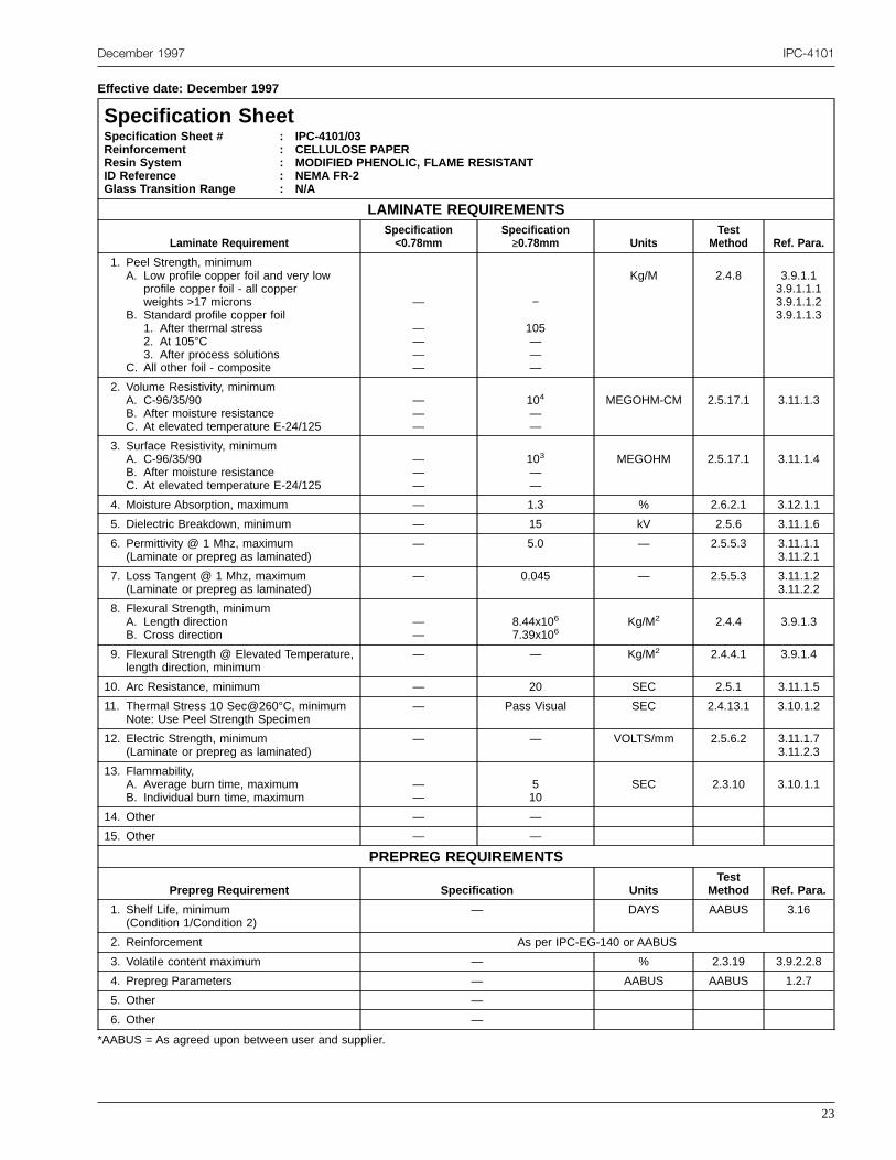
December 1997 IPC-4101
Effective date: December 1997
Specification SheetSpecification Sheet #ReinforcementResin SystemID ReferenceGlass Transition Range
: IPC-4101/03: CELLULOSE PAPER: MODIFIED PHENOLIC, FLAME RESISTANT: NEMA FR-2: N/A
LAMINATE REQUIREMENTS
Laminate RequirementSpecification<0.78mm
Specification≥0.78mm Units
TestMethod Ref. Para.
1. Peel Strength, minimumA. Low profile copper foil and very low
profile copper foil - all copperweights >17 microns
B. Standard profile copper foil1. After thermal stress2. At 105°C3. After process solutions
C. All other foil - composite
—
————
−
105———
Kg/M 2.4.8 3.9.1.13.9.1.1.13.9.1.1.23.9.1.1.3
2. Volume Resistivity, minimumA. C-96/35/90B. After moisture resistanceC. At elevated temperature E-24/125
———
104
——
MEGOHM-CM 2.5.17.1 3.11.1.3
3. Surface Resistivity, minimumA. C-96/35/90B. After moisture resistanceC. At elevated temperature E-24/125
———
103
——
MEGOHM 2.5.17.1 3.11.1.4
4. Moisture Absorption, maximum — 1.3 % 2.6.2.1 3.12.1.1
5. Dielectric Breakdown, minimum — 15 kV 2.5.6 3.11.1.6
6. Permittivity @ 1 Mhz, maximum(Laminate or prepreg as laminated)
— 5.0 — 2.5.5.3 3.11.1.13.11.2.1
7. Loss Tangent @ 1 Mhz, maximum(Laminate or prepreg as laminated)
— 0.045 — 2.5.5.3 3.11.1.23.11.2.2
8. Flexural Strength, minimumA. Length directionB. Cross direction
——
8.44x10⁶
7.39x10⁶Kg/M2 2.4.4 3.9.1.3
9. Flexural Strength @ Elevated Temperature,length direction, minimum
— — Kg/M2 2.4.4.1 3.9.1.4
10. Arc Resistance, minimum — 20 SEC 2.5.1 3.11.1.5
11. Thermal Stress 10 Sec@260°C, minimumNote: Use Peel Strength Specimen
— Pass Visual SEC 2.4.13.1 3.10.1.2
12. Electric Strength, minimum(Laminate or prepreg as laminated)
— — VOLTS/mm 2.5.6.2 3.11.1.73.11.2.3
13. Flammability,A. Average burn time, maximumB. Individual burn time, maximum
——
510
SEC 2.3.10 3.10.1.1
14. Other — —
15. Other — —
PREPREG REQUIREMENTS
Prepreg Requirement Specification UnitsTest
Method Ref. Para.
1. Shelf Life, minimum(Condition 1/Condition 2)
— DAYS AABUS 3.16
2. Reinforcement As per IPC-EG-140 or AABUS
3. Volatile content maximum — % 2.3.19 3.9.2.2.8
4. Prepreg Parameters — AABUS AABUS 1.2.7
5. Other —
6. Other —
*AABUS = As agreed upon between user and supplier.
23

IPC-4101 December 1997
Effective date: December 1997
Specification SheetSpecification Sheet #ReinforcementResin SystemID ReferenceGlass Transition Range
: IPC-4101/04: CELLULOSE PAPER: MODIFIED EPOXY, FLAME RESISTANT: NEMA FR-3: N/A
LAMINATE REQUIREMENTS
Laminate RequirementSpecification<0.78mm
Specification≥0.78mm Units
TestMethod Ref. Para.
1. Peel Strength, minimumA. Low profile copper foil and very low
profile copper foil - all copperweights >17 microns
B. Standard profile copper foil1. After thermal stress2. At 105°C3. After process solutions
C. All other foil - composite
—
————
—
12580——
Kg/M 2.4.8 3.9.1.13.9.1.1.13.9.1.1.23.9.1.1.3
2. Volume Resistivity, minimumA. C-96/35/90B. After moisture resistanceC. At elevated temperature E-24/125
———
104
——
MEGOHM-CM 2.5.17.1 3.11.1.3
3. Surface Resistivity, minimumA. C-96/35/90B. After moisture resistanceC. At elevated temperature E-24/125
———
103
——
MEGOHM 2.5.17.1 3.11.1.4
4. Moisture Absorption, maximum — 1.0 % 2.6.2.1 3.12.1.1
5. Dielectric Breakdown, minimum — 30 kV 2.5.6 3.11.1.6
6. Permittivity @ 1 Mhz, maximum(Laminate or prepreg as laminated)
— 4.8 — 2.5.5.3 3.11.1.13.11.2.1
7. Loss Tangent @ 1 Mhz, maximum(Laminate or prepreg as laminated)
— 0.04 — 2.5.5.3 3.11.1.23.11.2.2
8. Flexural Strength, minimumA. Length directionB. Cross direction
——
1.41x10⁷
1.13x10⁷Kg/M2 2.4.4 3.9.1.3
9. Flexural Strength @ Elevated Temperature,length direction, minimum
— — Kg/M2 2.4.4.1 3.9.1.4
10. Arc Resistance, minimum — 20 SEC 2.5.1 3.11.1.5
11. Thermal Stress 10 Sec@260°C, minimumA. UnetchedB. Etched
——
Pass VisualPass Visual
SEC 2.4.13.1 3.10.1.2
12. Electric Strength, minimum(Laminate or prepreg as laminated)
— — VOLTS/mm 2.5.6.2 3.11.1.73.11.2.3
13. Flammability,A. Average burn time, maximumB. Individual burn time, maximum
——
510
SEC 2.3.10 3.10.1.1
14. Other — —
15. Other — —
PREPREG REQUIREMENTS
Prepreg Requirement Specification UnitsTest
Method Ref. Para.
1. Shelf Life, minimum(Condition 1/Condition 2)
— DAYS AABUS 3.16
2. Reinforcement As per IPC-EG-140 or AABUS
3. Volatile content maximum — % 2.3.19 3.9.2.2.8
4. Prepreg Parameters — AABUS AABUS 1.2.7
5. Other —
6. Other —
24

December 1997 IPC-4101
Effective date: December 1997
Specification SheetSpecification Sheet #ReinforcementResin SystemID ReferenceGlass Transition Range
: IPC-4101/10: WOVEN E-GLASS SURFACE / CELLULOSE PAPER CORE: MODIFIED EPOXY, FLAME RESISTANT: NEMA CEM-1: N/A
LAMINATE REQUIREMENTS
Laminate RequirementSpecification<0.78mm
Specification≥0.78mm Units
TestMethod Ref. Para.
1. Peel Strength, minimumA. Low profile copper foil and very low
profile copper foil - all copperweights >17 microns
B. Standard profile copper foil1. After thermal stress2. At 125°C3. After process solutions
C. All other foil - composite
—
————
—
105———
Kg/M 2.4.8 3.9.1.13.9.1.1.13.9.1.1.23.9.1.1.3
2. Volume Resistivity, minimumA. C-96/35/90B. After moisture resistanceC. At elevated temperature E-24/125
———
106
—103
MEGOHM-CM 2.5.17.1 3.11.1.3
3. Surface Resistivity, minimumA. C-96/35/90B. After moisture resistanceC. At elevated temperature E-24/125
———
104
—103
MEGOHM 2.5.17.1 3.11.1.4
4. Moisture Absorption, maximum — 0.5 % 2.6.2.1 3.12.1.1
5. Dielectric Breakdown, minimum — 40 kV 2.5.6 3.11.1.6
6. Permittivity @ 1 Mhz, maximum(Laminate or prepreg as laminated)
— 5.4 — 2.5.5.3 3.11.1.13.11.2.1
7. Loss Tangent @ 1 Mhz, maximum(Laminate or prepreg as laminated)
— 0.035 — 2.5.5.3 3.11.1.23.11.2.2
8. Flexural Strength, minimumA. Length directionB. Cross direction
——
2.11x10⁷
1.76x10⁷Kg/M2 2.4.4 3.9.1.3
9. Flexural Strength @ Elevated Temperature,length direction, minimum
— — Kg/M2 2.4.4.1 3.9.1.4
10. Arc Resistance, minimum — 60 SEC 2.5.1 3.11.1.5
11. Thermal Stress 20 Sec@260°C, minimumA. UnetchedB. Etched
——
Pass Visual—
SEC 2.4.13.1 3.10.1.2
12. Electric Strength, minimum(Laminate or prepreg as laminated)
— — VOLTS/mm 2.5.6.2 3.11.1.73.11.2.3
13. Flammability,A. Average burn time, maximumB. Individual burn time, maximum
——
510
SEC 2.3.10 3.10.1.1
14. Other — —
15. Other — —
PREPREG REQUIREMENTS
Prepreg Requirement Specification UnitsTest
Method Ref. Para.
1. Shelf Life, minimum(Condition 1/Condition 2)
— DAYS AABUS 3.16
2. Reinforcement As per IPC-EG-140 or AABUS
3. Volatile content maximum — % 2.3.19 3.9.2.2.8
4. Prepreg Parameters — AABUS AABUS 1.2.7
5. Other —
6. Other —
*AABUS = As agreed upon between user and supplier.
25

IPC-4101 December 1997
Effective date: December 1997
Specification SheetSpecification Sheet #ReinforcementResin SystemID ReferenceGlass Transition Range
: IPC-4101/11: WOVEN E-GLASS FACE SHEETS / E-GLASS FELT CORE: POLYESTER, FLAME RESISTANT: NEMA CRM-5: 80°C MINIMUM
LAMINATE REQUIREMENTS
Laminate RequirementSpecification<0.78mm
Specification≥0.78mm Units
TestMethod Ref. Para.
1. Peel Strength, minimumA. Low profile copper foil and very low
profile copper foil - all copperweights >17 microns
B. Standard profile copper foil1. After thermal stress2. At 125°C3. After process solutions
C. All other foil - composite
—
————
90AABUS70—
Kg/M 2.4.8 3.9.1.13.9.1.1.13.9.1.1.23.9.1.1.3
2. Volume Resistivity, minimumA. C-96/35/90B. After moisture resistanceC. At elevated temperature E-24/125
———
107
——
MEGOHM-CM 2.5.17.1 3.11.1.3
3. Surface Resistivity, minimumA. C-96/35/90B. After moisture resistanceC. At elevated temperature E-24/125
———
106
——
MEGOHM 2.5.17.1 3.11.1.4
4. Moisture Absorption, maximum — 0.5 % 2.6.2.1 3.12.1.1
5. Dielectric Breakdown, minimum — 40 kV 2.5.6 3.11.1.6
6. Permittivity @ 1 Mhz, maximum(Laminate or prepreg as laminated)
— 4.1 — 2.5.5.3 3.11.1.13.11.2.1
7. Loss Tangent @ 1 Mhz, maximum(Laminate or prepreg as laminated)
— 0.022 — 2.5.5.3 3.11.1.23.11.2.2
8. Flexural Strength, minimumA. Length directionB. Cross direction
——
2.46x10⁷
1.41x10⁷Kg/M2 2.4.4 3.9.1.3
9. Flexural Strength @ Elevated Temperature,length direction, minimum
— — Kg/M2 2.4.4.1 3.9.1.4
10. Arc Resistance, minimum — 60 SEC 2.5.1 3.11.1.5
11. Thermal Stress 20 Sec@260°C, minimumA. UnetchedB. Etched
——
Pass Visual—
SEC 2.4.13.1 3.10.1.2
12. Electric Strength, minimum(Laminate or prepreg as laminated)
— — VOLTS/mm 2.5.6.2 3.11.1.73.11.2.3
13. Flammability,A. Average burn time, maximumB. Individual burn time, maximum
——
510
SEC 2.3.10 3.10.1.1
14. Other — —
15. Other — —
PREPREG REQUIREMENTS
Prepreg Requirement Specification UnitsTest
Method Ref. Para.
1. Shelf Life, minimum(Condition 1/Condition 2)
— DAYS AABUS 3.16
2. Reinforcement As per IPC-EG-140 or AABUS
3. Volatile content maximum — % 2.3.19 3.9.2.2.8
4. Prepreg Parameters — AABUS AABUS 1.2.7
5. Other —
6. Other —
*AABUS = As agreed upon between user and supplier.
26

December 1997 IPC-4101
Effective date: December 1997
Specification SheetSpecification Sheet #ReinforcementResin SystemID ReferenceGlass Transition Range
: IPC-4101/12: WOVEN E-GLASS FACE / NON-WOVEN GLASS CORE: EPOXY, FLAME RESISTANT: NEMA CEM-3: N/A
LAMINATE REQUIREMENTS
Laminate RequirementSpecification<0.78mm
Specification≥0.78mm Units
TestMethod Ref. Para.
1. Peel Strength, minimumA. Low profile copper foil and very low
profile copper foil - all copperweights >17 microns
B. Standard profile copper foil1. After thermal stress2. At 105°C3. After process solutions
C. All other foil - composite
—
————
—
1059090—
Kg/M 2.4.8 3.9.1.13.9.1.1.13.9.1.1.23.9.1.1.3
2. Volume Resistivity, minimumA. C-96/35/90B. After moisture resistanceC. At elevated temperature E-24/125
———
106
—103
MEGOHM-CM 2.5.17.1 3.11.1.3
3. Surface Resistivity, minimumA. C-96/35/90B. After moisture resistanceC. At elevated temperature E-24/125
———
104
—103
MEGOHM 2.5.17.1 3.11.1.4
4. Moisture Absorption, maximum — 0.5 % 2.6.2.1 3.12.1.1
5. Dielectric Breakdown, minimum — 40 kV 2.5.6 3.11.1.6
6. Permittivity @ 1 Mhz, maximum(Laminate or prepreg as laminated)
— 5.4 — 2.5.5.3 3.11.1.13.11.2.1
7. Loss Tangent @ 1 Mhz, maximum(Laminate or prepreg as laminated)
— 0.035 — 2.5.5.3 3.11.1.23.11.2.2
8. Flexural Strength, minimumA. Length directionB. Cross direction
——
2.32x10⁷
1.90x10⁷Kg/M2 2.4.4 3.9.1.3
9. Flexural Strength @ Elevated Temperature,length direction, minimum
— — Kg/M2 2.4.4.1 3.9.1.4
10. Arc Resistance, minimum — 60 SEC 2.5.1 3.11.1.5
11. Thermal Stress 20 Sec@260°C, minimumA. UnetchedB. Etched
——
Pass Visual—
SEC 2.4.13.1 3.10.1.2
12. Electric Strength, minimum(Laminate or prepreg as laminated)
— — VOLTS/mm 2.5.6.2 3.11.1.73.11.2.3
13. Flammability,A. Average burn time, maximumB. Individual burn time, maximum
——
510
SEC 2.3.10 3.10.1.1
14. Other — —
15. Other — —
PREPREG REQUIREMENTS
Prepreg Requirement Specification UnitsTest
Method Ref. Para.
1. Shelf Life, minimum(Condition 1/Condition 2)
— DAYS AABUS 3.16
2. Reinforcement As per IPC-EG-140 or AABUS
3. Volatile content maximum — % 2.3.19 3.9.2.2.8
4. Prepreg Parameters — AABUS AABUS 1.2.7
5. Other —
6. Other —
*AABUS = As agreed upon between user and supplier.
27

IPC-4101 December 1997
Effective date: December 1997
Specification SheetSpecification Sheet #ReinforcementResin SystemID ReferenceGlass Transition Range
: IPC-4101/20: WOVEN E-GLASS FABRIC: EPOXY, NON-FLAME RESISTANT: NEMA G-10, MIL-S-13949/03 - GEN: 100°C MINIMUM
LAMINATE REQUIREMENTS
Laminate RequirementSpecification<0.78mm
Specification≥0.78mm Units
TestMethod Ref. Para.
1. Peel Strength, minimumA. Low profile copper foil and very low
profile copper foil - all copperweights >17 microns
B. Standard profile copper foil1. After thermal stress2. At 125°C3. After process solutions
C. All other foil - composite
AABUS
80——
ABBUS
AABUS
1057080
ABBUS
Kg/M 2.4.8 3.9.1.13.9.1.1.13.9.1.1.23.9.1.1.3
2. Volume Resistivity, minimumA. C-96/35/90B. After moisture resistanceC. At elevated temperature E-24/125
106
—103
—106
103
MEGOHM-CM 2.5.17.1 3.11.1.3
3. Surface Resistivity, minimumA. C-96/35/90B. After moisture resistanceC. At elevated temperature E-24/125
104
—103
—104
103
MEGOHM 2.5.17.1 3.11.1.4
4. Moisture Absorption, maximum 0.80 0.35 % 2.6.2.1 3.12.1.1
5. Dielectric Breakdown, minimum — 40 kV 2.5.6 3.11.1.6
6. Permittivity @ 1 Mhz, maximum(Laminate or prepreg as laminated)
5.4 5.4 — 2.5.5.3 3.11.1.13.11.2.1
7. Loss Tangent @ 1 Mhz, maximum(Laminate or prepreg as laminated)
0.035 0.035 — 2.5.5.3 3.11.1.23.11.2.2
8. Flexural Strength, minimumA. Length directionB. Cross direction
——
4.22x10⁷
3.52x10⁷Kg/M2 2.4.4 3.9.1.3
9. Flexural Strength @ Elevated Temperature,length direction, minimum
— — Kg/M2 2.4.4.1 3.9.1.4
10. Arc Resistance, minimum 60 60 SEC 2.5.1 3.11.1.5
11. Thermal Stress 10 Sec@288°C, minimumA. UnetchedB. Etched
Pass VisualPass Visual
Pass VisualPass Visual
SEC 2.4.13.1 3.10.1.2
12. Electric Strength, minimum(Laminate or prepreg as laminated)
2.90x10⁴ — VOLTS/mm 2.5.6.2 3.11.1.73.11.2.3
13. Flammability,A. Average burn time, maximumB. Individual burn time, maximum
——
——
SEC 2.3.10 3.10.1.1
14. Other — —
15. Other — —
PREPREG REQUIREMENTS
Prepreg Requirement Specification UnitsTest
Method Ref. Para.
1. Shelf Life, minimum(Condition 1/Condition 2)
180 (<5°C) DAYS AABUS 3.16
2. Reinforcement As per IPC-EG-140 or AABUS
3. Volatile content maximum 0.75 % 2.3.19 3.9.2.2.8
4. Prepreg Parameters — AABUS AABUS 1.2.7
5. Other —
6. Other —
*AABUS = As agreed upon between user and supplier.
28

December 1997 IPC-4101
Effective date: December 1997
Specification SheetSpecification Sheet #ReinforcementResin SystemID ReferenceGlass Transition Range
: IPC-4101/21: WOVEN E-GLASS FABRIC: EPOXY, FLAME RESISTANT: NEMA FR-4, MIL-S-13949/04 - GF/GFN/GFK: 110°C MINIMUM
LAMINATE REQUIREMENTS
Laminate RequirementSpecification<0.78mm
Specification≥0.78mm Units
TestMethod Ref. Para.
1. Peel Strength, minimumA. Low profile copper foil and very low
profile copper foil - all copperweights >17 microns
B. Standard profile copper foil1. After thermal stress2. At 125°C3. After process solutions
C. All other foil - composite
70
807055
AABUS
70
1057080
AABUS
Kg/M 2.4.8 3.9.1.13.9.1.1.13.9.1.1.23.9.1.1.3
2. Volume Resistivity, minimumA. C-96/35/90B. After moisture resistanceC. At elevated temperature E-24/125
106
—103
—106
103
MEGOHM-CM 2.5.17.1 3.11.1.3
3. Surface Resistivity, minimumA. C-96/35/90B. After moisture resistanceC. At elevated temperature E-24/125
104
—103
—104
103
MEGOHM 2.5.17.1 3.11.1.4
4. Moisture Absorption, maximum 0.80 0.35 % 2.6.2.1 3.12.1.1
5. Dielectric Breakdown, minimum — 40 kV 2.5.6 3.11.1.6
6. Permittivity @ 1 Mhz, maximum(Laminate or prepreg as laminated)
5.4 5.4 — 2.5.5.3 3.11.1.13.11.2.1
7. Loss Tangent @ 1 Mhz, maximum(Laminate or prepreg as laminated)
0.035 0.035 — 2.5.5.3 3.11.1.23.11.2.2
8. Flexural Strength, minimumA. Length directionB. Cross direction
——
4.23x10⁷
3.52x10⁷Kg/M2
2.4.43.9.1.3
9. Flexural Strength @ Elevated Temperature,length direction, minimum
— — Kg/M2 2.4.4.1 3.9.1.4
10. Arc Resistance, minimum 60 60 SEC 2.5.1 3.11.1.5
11. Thermal Stress 10 Sec@288°C, minimumA. UnetchedB. Etched
Pass VisualPass Visual
Pass VisualPass Visual
SEC 2.4.13.1 3.10.1.2
12. Electric Strength, minimum(Laminate or prepreg as laminated)
2.90x10⁴ — VOLTS/mm 2.5.6.2 3.11.1.73.11.2.3
13. Flammability,A. Average burn time, maximumB. Individual burn time, maximum
510
510
SEC 2.3.10 3.10.1.1
14. Other — —
15. Other — —
PREPREG REQUIREMENTS
Prepreg Requirement Specification UnitsTest
Method Ref. Para.
1. Shelf Life, minimum(Condition 1/Condition 2)
180 (<5°C) DAYS AABUS 3.16
2. Reinforcement As per IPC-EG-140 or AABUS
3. Volatile content maximum 0.75 % 2.3.19 3.9.2.2.8
4. Prepreg Parameters — AABUS AABUS 1.2.7
5. Flammability,A. Average burn time, maximumB. Individual burn time, maximum
510
SEC 2.3.10 3.10.2.1
6. Other —
*AABUS = As agreed upon between user and supplier.
29

IPC-4101 December 1997
Effective date: December 1997
Specification SheetSpecification Sheet #ReinforcementResin SystemID ReferenceGlass Transition Range
: IPC-4101/22: WOVEN E-GLASS FABRIC: EPOXY, HOT STRENGTH RETENTION, NON-FLAME RESISTANT: NEMA G-11 - GB: 135°C - 175°C
LAMINATE REQUIREMENTS
Laminate RequirementSpecification<0.78mm
Specification≥0.78mm Units
TestMethod Ref. Para.
1. Peel Strength, minimumA. Low profile copper foil and very low
profile copper foil - all copperweights >17 microns
B. Standard profile copper foil1. After thermal stress2. At 150°C3. After process solutions
C. All other foil - composite
AABUS
1058080
AABUS
AABUS
1459090
AABUS
Kg/M 2.4.8 3.9.1.13.9.1.1.13.9.1.1.23.9.1.1.3
2. Volume Resistivity, minimumA. C-96/35/90B. After moisture resistanceC. At elevated temperature E-24/150
107
—105
—107
105
MEGOHM-CM 2.5.17.1 3.11.1.3
3. Surface Resistivity, minimumA. C-96/35/90B. After moisture resistanceC. At elevated temperature E-24/150
108
—105
—108
105
MEGOHM 2.5.17.1 3.11.1.4
4. Moisture Absorption, maximum 0.80 0.35 % 2.6.2.1 3.12.1.1
5. Dielectric Breakdown, minimum 40 40 kV 2.5.6 3.11.1.6
6. Permittivity @ 1 Mhz, maximum(Laminate or prepreg as laminated)
5.4 5.4 — 2.5.5.3 3.11.1.13.11.2.1
7. Loss Tangent @ 1 Mhz, maximum(Laminate or prepreg as laminated)
0.035 0.035 — 2.5.5.3 3.11.1.23.11.2.2
8. Flexural Strength, minimumA. Length directionB. Cross direction
4.23x10⁷
3.52x1074.23x107
3.52x10⁷Kg/M2 2.4.4 3.9.1.3
9. Flexural Strength @ Elevated Temperature,length direction, minimum
2.11x10⁷ 2.11x10⁷ Kg/M2 2.4.4.1 3.9.1.4
10. Arc Resistance, minimum 90 90 SEC 2.5.1 3.11.1.5
11. Thermal Stress 10 Sec@288°C, minimumA. UnetchedB. Etched
Pass VisualPass Visual
Pass VisualPass Visual
SEC 2.4.13.1 3.10.1.2
12. Electric Strength, minimum(Laminate or prepreg as laminated)
2.90x10⁴ — VOLTS/mm 2.5.6.2 3.11.1.73.11.2.3
13. Flammability,A. Average burn time, maximumB. Individual burn time, maximum
——
——
SEC 2.3.10 3.10.1.1
14. Other — —
15. Other — —
PREPREG REQUIREMENTS
Prepreg Requirement Specification UnitsTest
Method Ref. Para.
1. Shelf Life, minimum(Condition 1/Condition 2)
180 (<5°C) DAYS AABUS 3.16
2. Reinforcement As per IPC-EG-140 or AABUS
3. Volatile content maximum 0.75 % 2.3.19 3.9.2.2.8
4. Prepreg Parameters — AABUS AABUS 1.2.7
5. Other —
6. Other —
30

December 1997 IPC-4101
Effective date: December 1997
Specification SheetSpecification Sheet #ReinforcementResin SystemID ReferenceGlass Transition Range
: IPC-4101/23: WOVEN E-GLASS FABRIC: EPOXY, HOT STRENGTH RETENTION, FLAME RESISTANT: NEMA FR-5, MILS-S-13949/05 - GH: 135°C - 175°C
LAMINATE REQUIREMENTS
Laminate RequirementSpecification<0.78mm
Specification≥0.78mm Units
TestMethod Ref. Para.
1. Peel Strength, minimumA. Low profile copper foil and very low
profile copper foil - all copperweights >17 microns
B. Standard profile copper foil1. After thermal stress2. At 150°C3. After process solutions
C. All other foil - composite
AABUS
1058080
AABUS
AABUS
1459090
AABUS
Kg/M 2.4.8 3.9.1.13.9.1.1.13.9.1.1.23.9.1.1.3
2. Volume Resistivity, minimumA. C-96/35/90B. After moisture resistanceC. At elevated temperature E-24/150
107
—105
—107
105
MEGOHM-CM 2.5.17.1 3.11.1.3
3. Surface Resistivity, minimumA. C-96/35/90B. After moisture resistanceC. At elevated temperature E-24/150
108
—105
—108
105
MEGOHM 2.5.17.1 3.11.1.4
4. Moisture Absorption, maximum 0.80 0.35 % 2.6.2.1 3.12.1.1
5. Dielectric Breakdown, minimum 40 40 kV 2.5.6 3.11.1.6
6. Permittivity @ 1 Mhz, maximum(Laminate or prepreg as laminated)
5.4 5.4 — 2.5.5.3 3.11.1.13.11.2.1
7. Loss Tangent @ 1 Mhz, maximum(Laminate or prepreg as laminated)
0.035 0.035 — 2.5.5.3 3.11.1.23.11.2.2
8. Flexural Strength, minimumA. Length directionB.Cross direction
——
4.23x10⁷
3.52x10⁷Kg/M2 2.4.4 3.9.1.3
9. Flexural Strength @ Elevated Temperature,length direction, minimum
— 2.11x10⁷ Kg/M2 2.4.4.1 3.9.1.4
10. Arc Resistance, minimum 90 90 SEC 2.5.1 3.11.1.5
11. Thermal Stress 10 Sec@288°C, minimumA. UnetchedB. Etched
Pass VisualPass Visual
Pass VisualPass Visual
SEC 2.4.13.1 3.10.1.2
12. Electric Strength, minimum(Laminate or prepreg as laminated)
2.90x10⁴ — VOLTS/mm 2.5.6.2 3.11.1.73.11.2.3
13. Flammability,A. Average burn time, maximumB. Individual burn time, maximum
510
510
SEC 2.3.10 3.10.1.1
14. Other — —
15. Other — —
PREPREG REQUIREMENTS
Prepreg Requirement Specification UnitsTest
Method Ref. Para.
1. Shelf Life, minimum(Condition 1/Condition 2)
180 (<5°C) DAYS AABUS 3.16
2. Reinforcement As per IPC-EG-140 or AABUS
3. Volatile content maximum 0.75 % 2.3.19 3.9.2.2.8
4. Prepreg Parameters — AABUS AABUS 1.2.7
5. Flammability,A. Average burn time, maximumB. Individual burn time, maximum
510
SEC 2.3.10 3.10.2.1
6. Other —
*AABUS = As agreed upon between user and supplier.
31

IPC-4101 December 1997
Effective date: December 1997
Specification SheetSpecification Sheet #ReinforcementResin SystemID ReferenceGlass Transition Range
: IPC-4101/24: WOVEN E-GLASS FABRIC: MAJORITY EPOXY MODIFIED OR UNMODIFIED, FLAME RESISTANT: NEMA FR-4, MIL-S-13949/04 - GF/GFG: 150°C - 200°C
LAMINATE REQUIREMENTS
Laminate RequirementSpecification<0.78mm
Specification≥0.78mm Units
TestMethod Ref. Para.
1. Peel Strength, minimumA. Low profile copper foil and very low
profile copper foil - all copperweights >17 microns
B. Standard profile copper foil1. After thermal stress2. At 125°C3. After process solutions
C. All other foil - composite
70
807055
AABUS
70
1057080
AABUS
Kg/M 2.4.8 3.9.1.13.9.1.1.13.9.1.1.23.9.1.1.3
2. Volume Resistivity, minimumA. C-96/35/90B. After moisture resistanceC. At elevated temperature E-24/125
106
—103
—106
103
MEGOHM-CM 2.5.17.1 3.11.1.3
3. Surface Resistivity, minimumA. C-96/35/90B. After moisture resistanceC. At elevated temperature E-24/125
104
—103
—104
103
MEGOHM 2.5.17.1 3.11.1.4
4. Moisture Absorption, maximum 0.80 0.35 % 2.6.2.1 3.12.1.1
5. Dielectric Breakdown, minimum — 40 kV 2.5.6 3.11.1.6
6. Permittivity @ 1 Mhz, maximum(Laminate or prepreg as laminated)
5.4 5.4 — 2.5.5.3 3.11.1.13.11.2.1
7. Loss Tangent @ 1 Mhz, maximum(Laminate or prepreg as laminated)
0.035 0.035 — 2.5.5.3 3.11.1.23.11.2.2
8. Flexural Strength, minimumA. Length directionB. Cross direction
——
4.23x10⁷
3.52x10⁷Kg/M2 2.4.4 3.9.1.3
9. Flexural Strength @ Elevated Temperature,length direction, minimum
— — Kg/M2 2.4.4.1 3.9.1.4
10. Arc Resistance, minimum 60 60 SEC 2.5.1 3.11.1.5
11. Thermal Stress 10 Sec@288°C, minimumA. UnetchedB. Etched
Pass VisualPass Visual
Pass VisualPass Visual
SEC 2.4.13.1 3.10.1.2
12. Electric Strength, minimum(Laminate or prepreg as laminated)
2.90x10⁴ — VOLTS/mm 2.5.6.2 3.11.1.73.11.2.3
13. Flammability,A. Average burn time, maximumB. Individual burn time, maximum
510
510
SEC 2.3.10 3.10.1.1
14. Glass Transition(Laminate or prepreg as laminated)
150-200 150-200 °C
15. Other — —
PREPREG REQUIREMENTS
Prepreg Requirement Specification UnitsTest
Method Ref. Para.
1. Shelf Life, minimum(Condition 1/Condition 2)
180/90 DAYS AABUS 3.16
2. Reinforcement As per IPC-EG-140 or AABUS
3. Volatile content maximum 0.75 % 2.3.19 3.9.2.2.8
4. Prepreg Parameters — AABUS AABUS 1.2.7
5. Flammability,A. Average burn time, maximumB. Individual burn time, maximum
510
SEC 2.3.10 3.10.2.1
6. Other —
*AABUS = As agreed upon between user and supplier.
32

December 1997 IPC-4101
Effective date: December 1997
Specification SheetSpecification Sheet #ReinforcementResin SystemID ReferenceGlass Transition Range
: IPC-4101/25: WOVEN GLASS: EPOXY / PPO, FLAME RESISTANT: NEMA FR-4, MIL-S-13949/04 - GF/GFG: 150°C - 200°C
LAMINATE REQUIREMENTS
Laminate RequirementSpecification<0.78mm
Specification≥0.78mm Units
TestMethod Ref. Para.
1. Peel Strength, minimumA. Low profile copper foil and very low
profile copper foil - all copperweights >17 microns
B. Standard profile copper foil.1. After thermal stress2. At 125°C3. After process solutions
C. All other foil - composite
—
70
807055
AABUS
70
1057080
AABUS
Kg/M 2.4.8 3.9.1.13.9.1.1.13.9.1.1.23.9.1.1.3
2. Volume Resistivity, minimumA. C-96/35/90B. After moisture resistanceC. At elevated temperature E-24/125
106
—103
—106
103
MEGOHM-CM 2.5.17.1 3.11.1.3
3. Surface Resistivity, minimumA. C-96/35/90B. After moisture resistanceC. At elevated temperature E-24/125
104
—103
—104
103
MEGOHM 2.5.17.1 3.11.1.4
4. Moisture Absorption, maximum .55 0.35 % 2.6.2.1 3.12.1.1
5. Dielectric Breakdown, minimum — 40 kV 2.5.6 3.11.1.6
6. Permittivity @ 1 Mhz, maximum(Laminate or prepreg as laminated)
4.4 4.4 — 2.5.5.3 3.11.1.13.11.2.1
7. Loss Tangent @ 1 Mhz, maximum(Laminate or prepreg as laminated)
0.035 0.035 — 2.5.5.3 3.11.1.23.11.2.2
8. Flexural Strength, minimumA. Length directionB. Cross direction
——
4.23x10⁶
3.52x10⁶Kg/M2 2.4.4.1 3.9.1.3
9. Flexural Strength @ Elevated Temperature,length direction, minimum
— — Kg/M2 2.4.4 3.9.14
10. Arc Resistance, minimum 60 60 SEC 2.5.1 3.11.1.5
11. Thermal Stress 10 Sec@288°C, minimumA. UnetchedB. Etched
Pass VisualPass Visual
Pass VisualPass Visual
SEC 2.4.13.1 3.10.1.2
12. Electric Strength, minimum(Laminate or prepreg as laminated)
2.90x10⁴ — VOLTS/mm 2.5.6.2 3.11.1.73.11.2.3
13. Flammability,A. Average burn time, maximumB. Individual burn time, maximum
510
510
SEC 2.3.10 3.10.11
14. Other — —
15. Other — —
PREPREG REQUIREMENTS
Prepreg Requirement Specification UnitsTest
Method Ref. Para.
1. Shelf Life, minimum(Condition 1/Condition 2)
90 DAYS AABUS 3.16
2. Reinforcement As per IPC-EG-140 or AABUS
3. Volatile content maximum 0.5 % 2.3.19 3.9.2.2.8
4. Prepreg Parameters — AABUS AABUS 1.2.7
5. Flammability,A. Average burn time, maximumB. Individual burn time, maximum
510
SEC 2.3.10 3.10.2.1
6. Other —
*AABUS = As agreed upon between user and supplier.
33

IPC-4101 December 1997
Effective date: December 1997
Specification SheetSpecification Sheet #ReinforcementResin SystemID ReferenceGlass Transition Range
: IPC-4101/26: WOVEN GLASS: MAJORITY EPOXY MODIFIED OR UNMODIFIED, FLAME RESISTANT: NEMA FR-4, MIL-S-13949/04 - GF/GFT: 170°C - 220°C
LAMINATE REQUIREMENTS
Laminate RequirementSpecification<0.78mm
Specification≥0.78mm Units
TestMethod Ref. Para.
1. Peel Strength, minimumA. Low profile copper foil and very low
profile copper foil - all copperweight >17 microns
B. Standard profile copper foil1. After thermal stress2. At 125°C3. After process solutions
C. All other foil - composite
70
807055
AABUS
70
1057080
AABUS
Kg/M 2.4.8 3.9.1.13.9.1.1.13.9.1.1.23.9.1.1.3
2. Volume Resistivity, minimumA. C-96/35/90B. After moisture resistanceC. At elevated temperature E-24/125
106
—10
3
—106
103
MEGOHM-CM 2.5.17.1 3.11.1.3
3. Surface Resistivity, minimumA. C-96/35/90B. After moisture resistanceC. At elevated temperature E-24/125
104
—10
3
—104
103
MEGOHM 2.5.17.1 3.11.1.4
4. Moisture Absorption, maximum 0.80 0.35 % 2.6.2.1 3.12.1.1
5. Dielectric Breakdown, minimum — 40 kV 2.5.6 3.11.1.6
6. Permittivity @ 1 Mhz, maximum(Laminate or prepreg as laminated)
5.4 5.4 — 2.5.5.3 3.11.1.13.11.2.1
7. Loss Tangent @ 1 Mhz, maximum(Laminate or prepreg as laminated)
0.035 0.030 — 2.5.5.3 3.11.1.23.11.2.2
8. Flexural Strength, minimumA. Length directionB. Cross direction
——
4.23x10⁷
3.52x10⁷Kg/M2 2.4.4 3.9.1.3
9. Flexural Strength @ Elevated Temperature,length direction, minimum
— — Kg/M2 2.4.4.1 3.9.1.4
10. Arc Resistance, minimum 60 60 SEC 2.5.1 3.11.1.5
11. Thermal Stress 10 Sec@288°C, minimumA. UnetchedB. Etched
Pass VisualPass Visual
Pass VisualPass Visual
SEC 2.4.13.1 3.10.1.2
12. Electric Strength, minimum(Laminate or prepreg as laminated)
2.90x10⁴ — VOLTS/mm 2.5.6.2 3.11.1.73.11.2.3
13. Flammability,A. Average burn time, maximumB. Individual burn time, maximum
510
510
SEC 2.3.10 3.10.1.1
14. Other — —
15. Other — —
PREPREG REQUIREMENTS
Prepreg Requirement Specification UnitsTest
Method Ref. Para.
1. Shelf Life, minimum(Condition 1/Condition 2)
90 DAYS AABUS 3.16
2. Reinforcement As per IPC-EG-140 or AABUS
3. Volatile content maximum 0.5 % 2.3.19 3.9.2.2.8
4. Prepreg Parameters — AABUS AABUS 1.2.7
5 Flammability,A. Average burn time, maximumB. Individual burn time, maximum
510
SEC 2.3.10 3.10.2.1
6. Other —
*AABUS = As agreed upon between user and supplier.
34

December 1997 IPC-4101
Effective date: December 1997
Specification SheetSpecification Sheet #ReinforcementResin SystemID ReferenceGlass Transition Range
: IPC-4101/27: UNIDIRECTIONAL, CROSS-PLIED FIBERGLASS: MAJORITY EPOXY, FLAME RESISTANT: NONE: 110°C - MINIMUM
LAMINATE REQUIREMENTS
Laminate RequirementSpecification<0.78mm
Specification≥0.78mm Units
TestMethod Ref. Para.
1. Peel Strength, minimumA. Low profile copper foil and very low
profile copper foil - all copperweight >17 microns
B. Standard profile copper foil1. After thermal stress2. At 125°C3. After process solutions
C. All other foil - composite
70
807055
AABUS
70
1057080
AABUS
Kg/M 2.4.8 3.9.1.13.9.1.1.13.9.1.1.23.9.1.1.3
2. Volume Resistivity, minimumA. C-96/35/90B. After moisture resistanceC. At elevated temperature E-24/125
106
—10
3
—106
103
MEGOHM-CM 2.5.17.1 3.11.1.3
3. Surface Resistivity, minimumA. C-96/35/90B. After moisture resistanceC. At elevated temperature E-24/125
104
—10
3
—104
103
MEGOHM 2.5.17.1 3.11.1.4
4. Moisture Absorption, maximum 0.80 0.35 % 2.6.2.1 3.12.1.1
5. Dielectric Breakdown, minimum — 40 kV 2.5.6 3.11.1.6
6. Permittivity @ 1 Mhz, maximum(Laminate or prepreg as laminated)
5.4 5.4 — 2.5.5.3 3.11.1.13.11.2.1
7. Loss Tangent @ 1 Mhz, maximum(Laminate or prepreg as laminated)
0.035 0.030 — 2.5.5.3 3.11.1.23.11.2.2
8. Flexural Strength, minimumA. Length directionB. Cross direction
——
3.0x10⁷
3.0x10⁷Kg/M2 2.4.4 3.9.1.3
9. Flexural Strength @ Elevated Temperature,length direction, minimum
— — Kg/M2 2.4.4.1 3.9.1.4
10. Arc Resistance, minimum 60 60 SEC 2.5.1 3.11.1.5
11. Thermal Stress 10 Sec@288°C, minimumA. UnetchedB. Etched
Pass VisualPass Visual
Pass VisualPass Visual
SEC 2.4.13.1 3.10.1.2
12. Electric Strength, minimum(Laminate or prepreg as laminated)
2.90x10⁴ — VOLTS/mm 2.5.6.2 3.11.1.73.11.2.3
13. Flammability,A. Average burn time, maximumB. Individual burn time, maximum
510
510
SEC 2.3.10 3.10.1.1
14. Other — —
15. Other — —
PREPREG REQUIREMENTS
Prepreg Requirement Specification UnitsTest
Method Ref. Para.
1. Shelf Life, minimum(Condition 1/Condition 2)
90 DAYS AABUS 3.16
2. Reinforcement As per IPC-EG-140 or AABUS
3. Volatile content maximum 0.5 % 2.3.19 3.9.2.2.8
4. Prepreg Parameters — AABUS AABUS 1.2.7
5 Flammability,A. Average burn time, maximumB. Individual burn time, maximum
510
SEC 2.3.10 3.10.2.1
6. Other —
*AABUS = As agreed upon between user and supplier.
35
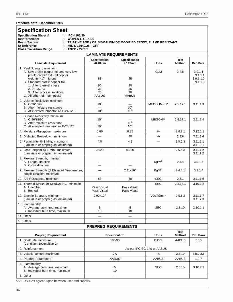
IPC-4101 December 1997
Effective date: December 1997
Specification SheetSpecification Sheet #ReinforcementResin SystemID ReferenceGlass Transition Range
: IPC-4101/30: WOVEN E-GLASS: TRIAZINE AND / OR BISMALEIMIDE MODIFIED EPOXY, FLAME RESISTANT: MIL-S-13949/26 - GFT: 170°C - 220°C
LAMINATE REQUIREMENTS
Laminate RequirementSpecification<0.78mm
Specification≥0.78mm Units
TestMethod Ref. Para.
1. Peel Strength, minimumA. Low profile copper foil and very low
profile copper foil - all copperweights >17 microns
B. Standard profile copper foil1. After thermal stress2. At 150°C3. After process solutions
C. All other foil - composite
55
903570
AABUS
55
903570
AABUS
Kg/M 2.4.8 3.9.1.13.9.1.1.13.9.1.1.23.9.1.1.3
2. Volume Resistivity, minimumA. C-96/35/90B. After moisture resistanceC. At elevated temperature E-24/125
106
—105
—106
105
MEGOHM-CM 2.5.17.1 3.11.1.3
3. Surface Resistivity, minimumA. C-96/35/90B. After moisture resistanceC. At elevated temperature E-24/125
106
—105
—106
105
MEGOHM 2.5.17.1 3.11.1.4
4. Moisture Absorption, maximum 0.80 0.35 % 2.6.2.1 3.12.1.1
5. Dielectric Breakdown, minimum — 40 kV 2.5.6 3.11.1.6
6. Permittivity @ 1 Mhz, maximum(Laminate or prepreg as laminated)
4.8 4.8 — 2.5.5.3 3.11.1.13.11.2.1
7. Loss Tangent @ 1 Mhz, maximum(Laminate or prepreg as laminated)
0.020 0.020 — 2.5.5.3 3.11.1.23.11.2.2
8. Flexural Strength, minimumA. Length directionB. Cross direction
——
——
Kg/M2 2.4.4 3.9.1.3
9. Flexural Strength @ Elevated Temperature,length direction, minimum
— 2.11x10⁷ Kg/M2 2.4.4.1 3.9.1.4
10. Arc Resistance, minimum 60 60 SEC 2.5.1 3.11.1.5
11. Thermal Stress 10 Sec@288°C, minimumA. UnetchedB. Etched
Pass VisualPass Visual
Pass VisualPass Visual
SEC 2.4.13.1 3.10.1.2
12. Electric Strength, minimum(Laminate or prepreg as laminated)
2.90x10⁴ — VOLTS/mm 2.5.6.2 3.11.1.73.11.2.3
13. Flammability,A. Average burn time, maximumB. Individual burn time, maximum
510
510
SEC 2.3.10 3.10.1.1
14. Other — —
15. Other — —
PREPREG REQUIREMENTS
Prepreg Requirement Specification UnitsTest
Method Ref. Para.
1. Shelf Life, minimum(Condition 1/Condition 2)
180/90 DAYS AABUS 3.16
2. Reinforcement As per IPC-EG-140 or AABUS
3. Volatile content maximum 2.0 % 2.3.19 3.9.2.2.8
4. Prepreg Parameters AABUS AABUS AABUS 1.2.7
5. Flammability,A. Average burn time, maximumB. Individual burn time, maximum
510
SEC 2.3.10 3.10.2.1
6. Other —
*AABUS = As agreed upon between user and supplier.
36

December 1997 IPC-4101
Effective date: December 1997
Specification SheetSpecification Sheet #ReinforcementResin SystemID ReferenceGlass Transition Range
: IPC-4101/40: WOVEN E-GLASS: POLYIMIDE: MIL-S-13949/10 - GI/GIN: 200°C MINIMUM
LAMINATE REQUIREMENTS
Laminate RequirementSpecification<0.78mm
Specification≥0.78mm Units
TestMethod Ref. Para.
1. Peel Strength, minimumA. Low profile copper foil and very low
profile copper foil - all copperweights >17 microns
B. Standard profile copper foil1. After thermal stress2. At 170°C3. After process solutions
C. All other foil - composite
AABUS
907080—
AABUS
1057095—
Kg/M 2.4.8 3.9.1.13.9.1.1.13.9.1.1.23.9.1.1.3
2. Volume Resistivity, minimumA. After moisture resistanceB. At elevated temperature E-24/204
104
6 x104106
106MEGOHM-CM 2.5.17.1 3.11.1.3
3. Surface Resistivity, minimumA. After moisture resistanceB. At elevated temperature E-24/204
104
6 x104106
106MEGOHM 2.5.17.1 3.11.1.4
4. Moisture Absorption, maximum 0.51≤t≤0.78mm1.0
0.78≤t≤1.54mm1.0
1.55≤t≤6.35mm0.5
% 2.6.2.1 3.12.1.1
5. Dielectric Breakdown, minimum — 40 kV 2.5.6 3.11.1.6
6. Permittivity @ 1 Mhz, maximum(Laminate or prepreg as laminated)
5.4 5.4 — 2.5.5.3 3.11.1.13.11.2.1
7. Loss Tangent @ 1 Mhz, maximum(Laminate or prepreg as laminated)
0.035 0.035 — 2.5.5.3 3.11.1.23.11.2.2
8. Flexural Strength, minimumA. Length directionB. Cross direction
——
4.23x10⁷
3.31x10⁷Kg/M2 2.4.4 3.9.1.3
9. Flexural Strength @ Elevated Temperature,E-1/204, Length direction, minimum
— 3.17x10⁷ Kg/M2 2.4.4.1 3.9.1.4
10. Arc Resistance, minimum 120 120 SEC 2.5.1 3.11.1.5
11. Thermal Stress 10 Sec@288°C, minimumA. UnetchedB. Etched
Pass VisualPass Visual
Pass VisualPass Visual
SEC 2.4.13.1 3.10.1.2
12. Electric Strength, minimum(Laminate or prepreg as laminated)
2.90x10⁴ — VOLTS/mm 2.5.6.2 3.11.1.73.11.2.3
13. Flammability, maximumA. Average burn time, maximumB. Individual burn time, maximum
——
——
SEC 2.3.10 3.10.1.1
14. Other — —
15. Other — —
PREPREG REQUIREMENTS
Prepreg Requirement Specification UnitsTest
Method Ref. Para.
1. Shelf Life, minimum(Condition 1/Condition 2)
180/90 DAYS AABUS 3.16
2. Reinforcement As per IPC-EG-140 or AABUS
3. Volatile content maximum 4.0 % 2.3.19 3.9.2.2.8
4. Prepreg Parameters — AABUS AABUS 1.2.7
5. Other —
6. Other —
*AABUS = As agreed upon between user and supplier.
37

IPC-4101 December 1997
Effective date: December 1997
Specification SheetSpecification Sheet #ReinforcementResin SystemID ReferenceGlass Transition Range
: IPC-4101/41: WOVEN E-GLASS: POLYIMIDE: MIL-S-13949/10 - GI/GIL: 250°C MINIMUM
LAMINATE REQUIREMENTS
Laminate RequirementSpecification<0.78mm
Specification≥0.78mm Units
TestMethod Ref. Para.
1. Peel Strength, minimumA. Low profile copper foil and very low
profile copper foil - all copperweights >17 microns
B. Standard profile copper foil1. After thermal stress2. At 170°C3. After process solutions
C. All other foil - composite
AABUS
706060
AABUS
AABUS
807070
AABUS
Kg/M 2.4.8 3.9.1.13.9.1.1.13.9.1.1.23.9.1.1.3
2. Volume Resistivity, minimumA. After moisture resistanceB. At elevated temperature E-24/204
104
6 x104106
106MEGOHM-CM 2.5.17.1 3.11.1.3
3. Surface Resistivity, minimumA. After moisture resistanceB. At elevated temperature E-24/204
104
6 x104106
106MEGOHM 2.5.17.1 3.11.1.4
4. Moisture Absorption, maximum 0.51≤t≤0.78mm1.0
0.78≤t≤1.54mm1.0
1.55≤t≤6.35mm0.5
% 2.6.2.1 3.12.1.1
5. Dielectric Breakdown, minimum — 40 kV 2.5.6 3.11.1.6
6. Permittivity @ 1 Mhz, maximum(Laminate or prepreg as laminated)
5.4 5.4 — 2.5.5.3 3.11.1.13.11.2.1
7. Loss Tangent @ 1 Mhz, maximumLaminate or prepreg as laminated)
0.035 0.035 — 2.5.5.3 3.11.1.2
8. Flexural Strength, minimumA. Length directionB. Cross direction
——
4.23x10⁷
3.17x10⁷Kg/M2 2.4.4 3.9.1.3
9. Flexural Strength @ Elevated Temperature,E-1/204, length direction, minimum
— 3.17x10⁷ Kg/M2 2.4.4.1 3.9.1.4
10. Arc Resistance, minimum 120 120 SEC 2.5.1 3.11.1.5
11. Thermal Stress 10 Sec@288°C, minimumA. UnetchedB. Etched
Pass VisualPass Visual
Pass VisualPass Visual
SEC 2.4.13.1 3.10.1.2
12. Electric Strength, minimum(Laminate or prepreg as laminated)
2.90x10⁴ — VOLTS/mm 2.5.6.2 3.11.1.73.11.2.3
13. Flammability, maximumA. Average burn time, maximumB. Individual burn time, maximum
——
——
SEC 2.3.10 3.10.1.1
14. Other — —
15. Other — —
PREPREG REQUIREMENTS
Prepreg Requirement Specification UnitsTest
Method Ref. Para.
1. Shelf Life, minimum(Condition 1/Condition 2)
180/90 DAYS AABUS 3.16
2. Reinforcement As per IPC-EG-140 or AABUS
3. Volatile content maximum 4.0 % 2.3.19 3.9.2.2.8
4. Prepreg Parameters — AABUS AABUS 1.2.7
5. Other —
6. Other —
*AABUS = As agreed upon between user and supplier.
38

December 1997 IPC-4101
Effective date: December 1997
Specification SheetSpecification Sheet #ReinforcementResin SystemID ReferenceGlass Transition Range
: IPC-4101/42: WOVEN E-GLASS: POLYIMIDE: MIL-S-13949/10 - GI/GIJ: 200°C - 250°C
LAMINATE REQUIREMENTS
Laminate RequirementSpecification<0.78mm
Specification≥0.78mm Units
TestMethod Ref. Para.
1. Peel Strength, minimumA. Low profile copper foil and very low
profile copper foil - all copperweights >17 microns
B. Standard profile copper foil1. After thermal stress2. At 170°C3. After process solutions
C. All other foil - composite
AABUS
907080
AABUS
AABUS
1057095
AABUS
Kg/M 2.4.8 3.9.1.13.9.1.1.13.9.1.1.23.9.1.1.3
2. Volume Resistivity, minimumA. After moisture resistanceB. At elevated temperature E-24/204
104
6 x104106
106MEGOHM-CM 2.5.17.1 3.11.1.3
3. Surface Resistivity, minimumA. After moisture resistanceB. At elevated temperature E-24/204
104
6 x104106
106MEGOHM 2.5.17.1 3.11.1.4
4. Moisture Absorption, maximum 0.51≤t≤0.78mm1.0
0.78≤t≤1.54mm1.0
1.55≤t≤6.35mm0.5
% 2.6.2.1 3.12.1.1
5. Dielectric Breakdown, minimum — 40 kV 2.5.6 3.11.1.6
6. Permittivity @ 1 Mhz, maximum(Laminate or prepreg as laminated)
5.4 5.4 — 2.5.5.3 3.11.1.13.11.2.1
7. Loss Tangent @ 1 Mhz, maximum(Laminate or prepreg as laminated)
0.035 0.035 — 2.5.5.3 3.11.1.23.11.2.2
8. Flexural Strength, minimumA. Length directionB. Cross direction
——
4.23x10⁷
3.17x10⁷Kg/M2 2.4.4 3.9.1.3
9. Flexural Strength @ Elevated Temperature,E-1/204, Length direction, minimum
— 3.17x10⁷ Kg/M2 2.4.4.1 3.9.1.4
10. Arc Resistance, minimum 120 120 SEC 2.5.1 3.11.1.5
11. Thermal Stress 10 Sec@288°C, minimumA. UnetchedB. Etched
Pass VisualPass Visual
Pass VisualPass Visual
SEC 2.4.13.1 3.10.1.2
12. Electric Strength, minimum(Laminate or prepreg as laminated)
2.90x10⁴ — VOLTS/mm 2.5.6.2 3.11.1.73.11.2.3
13. Flammability, maximumA. Average burn time, maximumB. Individual burn time, maximum
——
——
SEC 2.3.10 3.10.1.1
14. Other — —
15. Other — —
PREPREG REQUIREMENTS
Prepreg Requirement Specification UnitsTest
Method Ref. Para.
1. Shelf Life, minimum(Condition 1/Condition 2)
180/90 DAYS AABUS 3.16
2. Reinforcement As per IPC-EG-140 or AABUS
3. Volatile content maximum 4.0 % 2.3.19 3.9.2.2.8
4. Prepreg Parameters — AABUS AABUS 1.2.7
5. Other —
6. Other —
*AABUS = As agreed upon between user and supplier.
39
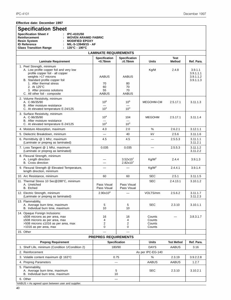
IPC-4101 December 1997
Effective date: December 1997
Specification SheetSpecification Sheet #ReinforcementResin SystemID ReferenceGlass Transition Range
: IPC-4101/50: WOVEN ARAMID FABRIC: MODIFIED EPOXY: MIL-S-13949/15 - AF: 135°C - 190°C
LAMINATE REQUIREMENTS
Laminate RequirementSpecification<0.78mm
Specification≥0.78mm Units
TestMethod Ref. Para.
1. Peel Strength, minimumA. Low profile copper foil and very low
profile copper foil - all copperweights >17 microns
B. Standard profile copper foil1. After thermal stress2. At 125°C3. After process solutions
C. All other foil - composite
AABUS
706055
AABUS
AABUS
807070
AABUS
Kg/M 2.4.8 3.9.1.13.9.1.1.13.9.1.1.23.9.1.1.3
2. Volume Resistivity, minimumA. C-96/35/90B. After moisture resistanceC. At elevated temperature E-24/125
106
—103
106
—103
MEGOHM-CM 2.5.17.1 3.11.1.3
3. Surface Resistivity, minimumA. C-96/35/90B. After moisture resistanceC. At elevated temperature E-24/125
104
—103
104—103
MEGOHM 2.5.17.1 3.11.1.4
4. Moisture Absorption, maximum 4.0 2.0 % 2.6.2.1 3.12.1.1
5. Dielectric Breakdown, minimum — 40 kV 2.5.6 3.11.1.6
6. Permittivity @ 1 Mhz, maximum(Laminate or prepreg as laminated)
4.5 4.5 — 2.5.5.3 3.11.1.13.11.2.1
7. Loss Tangent @ 1 Mhz, maximum(Laminate or prepreg as laminated)
0.035 0.035 — 2.5.5.3 3.11.1.23.11.2.2
8. Flexural Strength, minimumA. Length directionB. Cross direction
——
3.52x10⁷
2.82x10⁷Kg/M2 2.4.4 3.9.1.3
9. Flexural Strength @ Elevated Temperature,length direction, minimum
— — Kg/M2 2.4.4.1 3.9.1.4
10. Arc Resistance, minimum 60 60 SEC 2.5.1 3.11.1.5
11. Thermal Stress 10 Sec@288°C, minimumA. UnetchedB. Etched
Pass VisualPass Visual
Pass VisualPass Visual
SEC 2.4.13.1 3.10.1.2
12. Electric Strength, minimum(Laminate or prepreg as laminated)
2.90x10⁴ — VOLTS/mm 2.5.6.2 3.11.1.73.11.2.3
13. Flammability,A. Average burn time, maximumB. Individual burn time, maximum
510
510
SEC 2.3.10 3.10.1.1
14. Opaque Foreign Inclusions:≤508 microns as per area, max≤508 microns as per area, max>508 microns ≤1016 as per area, max>1016 as per area, max
16420
16420
CountsCountsCountsCounts
— 3.8.3.1.7
15. Other — —
PREPREG REQUIREMENTSPrepreg Requirement Specification Units Test Method Ref. Para.
1. Shelf Life, minimum (Condition 1/Condition 2) 180/90 DAYS AABUS 3.16
2. Reinforcement As per IPC-EG-140
3. Volatile content maximum @ 163°C 0.75 % 2.3.19 3.9.2.2.8
4. Prepreg Parameters — AABUS AABUS 1.2.7
5. Flammability,A. Average burn time, maximumB. Individual burn time, maximum
510
SEC 2.3.10 3.10.2.1
6. Other —*AABUS = As agreed upon between user and supplier.
40

December 1997 IPC-4101
Effective date: December 1997
Specification SheetSpecification Sheet #ReinforcementResin SystemID ReferenceGlass Transition Range
: IPC-4101/53: NON-WOVEN ARAMID: POLYIMIDE: MIL-S-13949/31 - BI: 220°C MINIMUM
LAMINATE REQUIREMENTS
Laminate RequirementSpecification<0.78mm
Specification≥0.78mm Units
TestMethod Ref. Para.
1. Peel Strength, minimumA. Low profile copper foil and very low
profile copper foil - all copperweights >17 microns
B. Standard profile copper foil1. After thermal stress2. At 125°C3. After process solutions
C. All other foil - composite
AABUS
555050
AABUS
AABUS
555050
AABUS
Kg/M 2.4.8 3.9.1.13.9.1.1.13.9.1.1.23.9.1.1.3
2. Volume Resistivity, minimumA. C-96/35/90B. After moisture resistanceC. At elevated temperature E-24/125
—106
103
—106
103
MEGOHM-CM 2.5.17.1 3.11.1.3
3. Surface Resistivity, minimumA. C-96/35/90B. After moisture resistanceC. At elevated temperature E-24/125
—104
103
—104
103
MEGOHM 2.5.17.1 3.11.1.4
4. Moisture Absorption, maximum 3.5 3.5 % 2.6.2.1 3.12.1.1
5. Dielectric Breakdown, minimum — 40 kV 2.5.6 3.11.1.6
6. Permittivity @ 1 Mhz, maximum(Laminate or prepreg as laminated)
4.5 4.5 — 2.5.5.3 3.11.1.13.11.2.1
7. Loss Tangent @ 1 Mhz, maximum(Laminate or prepreg as laminated)
0.035 0.035 — 2.5.5.3 3.11.1.23.11.2.2
8. Flexural Strength, minimumA. Length directionB. Cross direction
——
2.11x10⁷
2.11x10⁷Kg/M2 2.4.4 3.9.1.3
9. Flexural Strength @ Elevated Temperature,length direction, minimum
— — Kg/M2 2.4.4.1 3.9.1.4
10. Arc Resistance, minimum 60 60 SEC 2.5.1 3.11.1.5
11. Thermal Stress 10 Sec@288°C, minimumA. UnetchedB. Etched
Pass VisualPass Visual
Pass VisualPass Visual
SEC 2.4.13.1 3.10.1.2
12. Electric Strength, minimum(Laminate or prepreg as laminated)
1.93x10⁴[2.90x10⁴
— VOLTS/mm 2.5.6.2 3.11.1.73.11.2.3
13. Flammability,A. Average burn time, maximumB. Individual burn time, maximum
——
——
SEC 2.3.10 3.10.1.1
14. Other — —
15. Other — —
PREPREG REQUIREMENTS
Prepreg Requirement Specification UnitsTest
MethodRef.Para.
1. Shelf Life, minimum(Condition 1/Condition 2)
180/90 MONTHS AABUS 3.16
2. Reinforcement As per IPC-EG-140 or AABUS
3. Volatile content maximum 0.75 % 2.3.19 3.9.2.2.8
4. Prepreg Parameters — AABUS AABUS 1.2.7
5. Other —
6. Other —
*AABUS = Test Method as agreed upon between user and supplier.
41

IPC-4101 December 1997
Effective date: December 1997
Specification SheetSpecification Sheet #ReinforcementResin SystemID ReferenceGlass Transition Range
: IPC-4101/54: UNIDIRECTIONAL, CROSS PLIED, ARAMID FIBER: CYANATE ESTER RESIN: NONE: 230°C MINIMUM
LAMINATE REQUIREMENTS
Laminate RequirementSpecification<0.78mm
Specification≥0.78mm Units
TestMethod Ref. Para.
1. Peel Strength, minimumA. Low profile copper foil and very low
profile copper foil - all copperweights >17 microns
B. Standard profile copper foil1. After thermal stress2. At 170°C3. After process solutions
C. All other foil - composite
AABUS
70AABUS60
AABUS
AABUS
70AABUS60
AABUS
Kg/M 2.4.8 3.9.1.13.9.1.1.13.9.1.1.23.9.1.1.3
2. Volume Resistivity, minimumA. C-96/35/90B. After moisture resistanceC. At elevated temperature E-24/125
6x10⁴
—103
6x10⁴
—103
MEGOHM-CM 2.5.17.1 3.11.1.3
3. Surface Resistivity, minimumA. C-96/35/90B. After moisture resistanceC. At elevated temperature E-24/125
104
—103
104
—103
MEGOHM 2.5.17.1 3.11.1.4
4. Moisture Absorption, maximum 3.0 2.0 % 2.6.2.1 3.12.1.1
5. Dielectric Breakdown, minimum — 40 kV 2.5.6 3.11.1.6
6. Permittivity @ 1 Mhz, maximum(Laminate or prepreg as laminated)
4.2 4.2 — 2.5.5.3 3.11.1.13.11.2.1
7. Loss Tangent @ 1 Mhz, maximum(Laminate or prepreg as laminated)
0.025 0.025 — 2.5.5.3 3.11.1.23.11.2.2
8. Flexural Strength, minimumA. Length directionB. Cross direction
——
3.52x10⁷
2.82x10⁷Kg/M2 2.4.4 3.9.1.3
9. Flexural Strength @ Elevated Temperature,length direction, minimum
— — Kg/M2 2.4.4.1 3.9.1.4
10. Arc Resistance, minimum 60 60 SEC 2.5.1 3.11.1.5
11. Thermal Stress 10 Sec@288°C, minimumA. UnetchedB. Etched
Pass VisualPass Visual
Pass VisualPass Visual
SEC 2.4.13.1 3.10.1.2
12. Electric Strength, minimum(Laminate or prepreg as laminated)
2.90x10⁴ — VOLTS/mm 2.5.6.2 3.11.1.73.11.2.3
13. Flammability,A. Average burn time, maximumB. Individual burn time, maximum
510
510
SEC 2.3.10 3.10.1.1
14. Other — —
15. Other — —
PREPREG REQUIREMENTS
Prepreg Requirement Specification UnitsTest
Method Ref. Para.
1. Shelf Life, minimum(Condition 1/Condition 2)
180/90 DAYS AABUS 3.16
2. Reinforcement As per IPC-A-142
3. Volatile content maximum @ 163°C 1.5 % 2.3.19 3.9.2.2.8
4. Prepreg Parameters — AABUS AABUS 1.2.7
5. Flammability,A. Average burn time, maximumB. Individual burn time, maximum
510
SEC 2.3.10 3.10.2.1
6. Other —
*AABUS = As agreed upon between user and supplier.
42

December 1997 IPC-4101
Effective date: December 1997
Specification SheetSpecification Sheet #ReinforcementResin SystemID ReferenceGlass Transition Range
: IPC-4101/55: NON-WOVEN ARAMID: MODIFIED EPOXY: MIL-S-13949/22 - BF: 135°C - 190°C
LAMINATE REQUIREMENTS
Laminate RequirementSpecification<0.78mm
Specification≥0.78mm Units
TestMethod Ref. Para.
1. Peel Strength, minimumA. Low profile copper foil and very low
profile copper foil - all copperweights >17 microns
B. Standard profile copper foil1. After thermal stress2. At 125°C3. After process solutions
C. All other foil - composite
AABUS
555050
AABUS
AABUS
555050
AABUS
Kg/M 2.4.8 3.9.1.13.9.1.1.13.9.1.1.23.9.1.1.3
2. Volume Resistivity, minimumA. C-96/35/90B. After moisture resistanceC. At elevated temperature E-24/125
106
—103
106
—103
MEGOHM-CM 2.5.17.1 3.11.1.3
3. Surface Resistivity, minimumA. C-96/35/90B. After moisture resistanceC. At elevated temperature E-24/125
104
—103
104
—103
MEGOHM 2.5.17.1 3.11.1.4
4. Moisture Absorption, maximum 3.0 2.0 % 2.6.2.1 3.12.1.1
5. Dielectric Breakdown, minimum — 40 kV 2.5.6 3.11.1.6
6. Permittivity @ 1 Mhz, maximum(Laminate or prepreg as laminated)
4.0 4.0 — 2.5.5.3 3.11.1.13.11.2.1
7. Loss Tangent @ 1 Mhz, maximum(Laminate or prepreg as laminated)
0.025 0.025 — 2.5.5.3 3.11.1.23.11.2.2
8. Flexural Strength, minimumA. Length directionB. Cross direction
——
3.52x10⁷
2.82x10⁷Kg/M2 2.4.4 3.9.1.3
9. Flexural Strength @ Elevated Temperature,length direction, minimum
— — Kg/M2 2.4.4.1 3.9.1.4
10. Arc Resistance, minimum 60 60 SEC 2.5.1 3.11.1.5
11. Thermal Stress 10 Sec@288°C, minimumA. UnetchedB. Etched
Pass VisualPass Visual
Pass VisualPass Visual
SEC 2.4.13.1 3.10.1.2
12. Electric Strength, minimum(Laminate or prepreg as laminated)
5.80x10⁴ — VOLTS/mm 2.5.6.2 3.11.1.73.11.2.3
13. Flammability,A. Average burn time, maximumB. Individual burn time, maximum
510
510
SEC 2.3.10 3.10.1.1
14. Other — —
15. Other — —
PREPREG REQUIREMENTS
Prepreg Requirement Specification UnitsTest
Method Ref. Para.
1. Shelf Life, minimum(Condition 1/Condition 2)
180/90 DAYS AABUS 3.16
2. Reinforcement AABUS
3. Volatile content maximum @ 163°C 1.5 % 2.3.19 3.9.2.2.8
4. Prepreg Parameters — AABUS AABUS 1.2.7
5. Flammability,A. Average burn time, maximumB. Individual burn time, maximum
510
SEC 2.3.10 3.10.2.1
6. Other —
*AABUS = As agreed upon between user and supplier.
43

IPC-4101 December 1997
Effective date: December 1997
Specification SheetSpecification Sheet #ReinforcementResin SystemID ReferenceGlass Transition Range
: IPC-4101/60: WOVEN QUARTZ FABRIC: POLYIMIDE: MIL-S-13949/19 - QIL: 250°C MINIMUM
LAMINATE REQUIREMENTS
Laminate RequirementSpecification<0.78mm
Specification≥0.78mm Units
TestMethod Ref. Para.
1. Peel Strength, minimumA. Low profile copper foil and very low
profile copper foil - all copperweights >17 microns
B. Standard profile copper foil1. After thermal stress2. At 170°C3. After process solutions
C. All other foil - composite
AABUS
907080
AABUS
AABUS
1057095
AABUS
Kg/M 2.4.8 3.9.1.13.9.1.1.13.9.1.1.23.9.1.1.3
2. Volume Resistivity, minimumA. C-96/35/90B. After moisture resistanceC. At elevated temperature E-24/125
6x10⁴
—6x10⁴
—106
106
MEGOHM-CM 2.5.17.1 3.11.1.3
3. Surface Resistivity, minimumA. C-96/35/90B. After moisture resistanceC. At elevated temperature E-24/125
104
—6x10⁴
—106
106
MEGOHM 2.5.17.1 3.11.1.4
4. Moisture Absorption, maximum 1.25 0.5 % 2.6.2.1 3.12.1.1
5. Dielectric Breakdown, minimum — 40 kV 2.5.6 3.11.1.6
6. Permittivity @ 1 Mhz, maximum(Laminate or prepreg as laminated)
3.4 3.8 — 2.5.5.3 3.11.1.13.11.2.1
7. Loss Tangent @ 1 Mhz, maximum(Laminate or prepreg as laminated)
0.010 0.010 — 2.5.5.3 3.11.1.23.11.2.2
8. Flexural Strength, minimumA. Length directionB. Cross direction
——
4.23x10⁷
3.17x10⁷Kg/M2 2.4.4 3.9.1.3
9. Flexural Strength @ Elevated Temperature,length direction, minimum
— 3.17x10⁷ Kg/M2 2.4.4.1 3.9.1.4
10. Arc Resistance, minimum 120 120 SEC 2.5.1 3.11.1.5
11. Thermal Stress 10 Sec@288°C, minimumA. UnetchedB. Etched
Pass VisualPass Visual
Pass VisualPass Visual
SEC 2.4.13.1 3.10.1.2
12. Electric Strength, minimum(Laminate or prepreg as laminated)
2.90x10⁴ — VOLTS/mm 2.5.6.2 3.11.1.73.11.2.3
13. Flammability,A. Average burn time, maximumB. Individual burn time, maximum
——
——
SEC 2.3.10 3.10.1.1
14. Other — —
15. Other — —
PREPREG REQUIREMENTS
Prepreg Requirement Specification UnitsTest
Method Ref. Para.
1. Shelf Life, minimum(Condition 1/Condition 2)
180 (<5°C) DAYS AABUS 3.16
2. Reinforcement As per IPC-QF-143
3. Volatile content maximum @ 163°C 1.5 % 2.3.19 3.9.2.2.8
4. Prepreg Parameters — AABUS AABUS 1.2.7
5. Other —
6. Other —
*AABUS = Test Method as agreed upon between user and supplier.
44

December 1997 IPC-4101
Effective date: December 1997
Specification SheetSpecification Sheet #ReinforcementResin SystemID ReferenceGlass Transition Range
: IPC-4101/70: WOVEN S-2 GLASS: CYANATE ESTER: MIL-S-13949/27: 230°C MINIMUM
LAMINATE REQUIREMENTS
Laminate RequirementSpecification<0.78mm
Specification≥0.78mm Units
TestMethod Ref. Para.
1. Peel Strength, minimumA. Low profile copper foil and very low
profile copper foil - all copperweights >17 microns
B. Standard profile copper foil1. After thermal stress2. At 170°C3. After process solutions
C. All other foil - composite
AABUS
707070
AABUS
AABUS
707070
AABUS
Kg/M 2.4.8 3.9.1.13.9.1.1.13.9.1.1.23.9.1.1.3
2. Volume Resistivity, minimumA. C-96/35/90B. After moisture resistanceC. At elevated temperature E-24/125
106
—103
—106
103
MEGOHM-CM 2.5.17.1 3.11.1.3
3. Surface Resistivity, minimumA. C-96/35/90B. After moisture resistanceC. At elevated temperature E-24/125
104
—103
—104
103
MEGOHM 2.5.17.1 3.11.1.4
4. Moisture Absorption, maximum 3.0 3.0 % 2.6.2.1 3.12.1.1
5. Dielectric Breakdown, minimum — 40 kV 2.5.6 3.11.1.6
6. Permittivity @ 1 Mhz, maximum(Laminate or prepreg as laminated)
4.3 4.3 — 2.5.5.3 3.11.1.13.11.2.1
7. Loss Tangent @ 1 Mhz, maximum(Laminate or prepreg as laminated)
0.015 0.015 — 2.5.5.3 3.11.1.23.11.2.2
8. Flexural Strength, minimumA. Length directionB. Cross direction
——
3.52x10⁷
3.52x10⁷Kg/M2 2.4.4 3.9.1.3
9. Flexural Strength @ Elevated Temperature,length direction, minimum
— 2.82x10⁷ Kg/M2 2.4.4.1 3.9.1.4
10. Arc Resistance, minimum 120 120 SEC 2.5.1 3.11.1.5
11. Thermal Stress 10 Sec@288°C, minimumA. UnetchedB. Etched
Pass VisualPass Visual
Pass VisualPass Visual
SEC 2.4.13.1 3.10.1.2
12. Electric Strength, minimum(Laminate or prepreg as laminated)
2.90x10⁴ — VOLTS/mm 2.5.6.2 3.11.1.73.11.2.3
13. Flammability,A. Average burn time, maximumB. Individual burn time, maximum
510
510
SEC 2.3.10 3.10.1.1
14. Flexible Strength — —
15. Other — —
PREPREG REQUIREMENTS
Prepreg Requirement Specification UnitsTest
Method Ref. Para.
1. Shelf Life, minimum(Condition 1/Condition 2)
180/90 DAYS AABUS 3.16
2. Reinforcement As per IPC-EG-140 or AABUS
3. Volatile content maximum @ 163°C 3 % 2.3.19 3.9.2.2.8
4. Prepreg Parameters — AABUS AABUS 1.2.7
5. Flammability,A. Average burn time, maximumB. Individual burn time, maximum
510
SEC 2.3.10 3.10.2.1
6. Other —
*AABUS = Test Method as agreed upon between user and supplier.
45
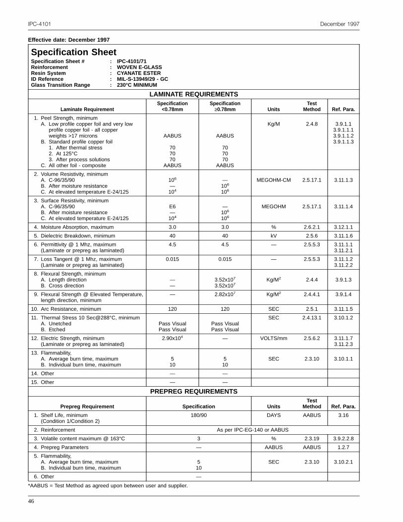
IPC-4101 December 1997
Effective date: December 1997
Specification SheetSpecification Sheet #ReinforcementResin SystemID ReferenceGlass Transition Range
: IPC-4101/71: WOVEN E-GLASS: CYANATE ESTER: MIL-S-13949/29 - GC: 230°C MINIMUM
LAMINATE REQUIREMENTS
Laminate RequirementSpecification<0.78mm
Specification≥0.78mm Units
TestMethod Ref. Para.
1. Peel Strength, minimumA. Low profile copper foil and very low
profile copper foil - all copperweights >17 microns
B. Standard profile copper foil1. After thermal stress2. At 125°C3. After process solutions
C. All other foil - composite
AABUS
707070
AABUS
AABUS
707070
AABUS
Kg/M 2.4.8 3.9.1.13.9.1.1.13.9.1.1.23.9.1.1.3
2. Volume Resistivity, minimumA. C-96/35/90B. After moisture resistanceC. At elevated temperature E-24/125
106
—104
—106
106
MEGOHM-CM 2.5.17.1 3.11.1.3
3. Surface Resistivity, minimumA. C-96/35/90B. After moisture resistanceC. At elevated temperature E-24/125
E6—104
—106
106
MEGOHM 2.5.17.1 3.11.1.4
4. Moisture Absorption, maximum 3.0 3.0 % 2.6.2.1 3.12.1.1
5. Dielectric Breakdown, minimum 40 40 kV 2.5.6 3.11.1.6
6. Permittivity @ 1 Mhz, maximum(Laminate or prepreg as laminated)
4.5 4.5 — 2.5.5.3 3.11.1.13.11.2.1
7. Loss Tangent @ 1 Mhz, maximum(Laminate or prepreg as laminated)
0.015 0.015 — 2.5.5.3 3.11.1.23.11.2.2
8. Flexural Strength, minimumA. Length directionB. Cross direction
——
3.52x10⁷
3.52x10⁷Kg/M2 2.4.4 3.9.1.3
9. Flexural Strength @ Elevated Temperature,length direction, minimum
— 2.82x10⁷ Kg/M2 2.4.4.1 3.9.1.4
10. Arc Resistance, minimum 120 120 SEC 2.5.1 3.11.1.5
11. Thermal Stress 10 Sec@288°C, minimumA. UnetchedB. Etched
Pass VisualPass Visual
Pass VisualPass Visual
SEC 2.4.13.1 3.10.1.2
12. Electric Strength, minimum(Laminate or prepreg as laminated)
2.90x10⁴ — VOLTS/mm 2.5.6.2 3.11.1.73.11.2.3
13. Flammability,A. Average burn time, maximumB. Individual burn time, maximum
510
510
SEC 2.3.10 3.10.1.1
14. Other — —
15. Other — —
PREPREG REQUIREMENTS
Prepreg Requirement Specification UnitsTest
Method Ref. Para.
1. Shelf Life, minimum(Condition 1/Condition 2)
180/90 DAYS AABUS 3.16
2. Reinforcement As per IPC-EG-140 or AABUS
3. Volatile content maximum @ 163°C 3 % 2.3.19 3.9.2.2.8
4. Prepreg Parameters — AABUS AABUS 1.2.7
5. Flammability,A. Average burn time, maximumB. Individual burn time, maximum
510
SEC 2.3.10 3.10.2.1
6. Other —
*AABUS = Test Method as agreed upon between user and supplier.
46
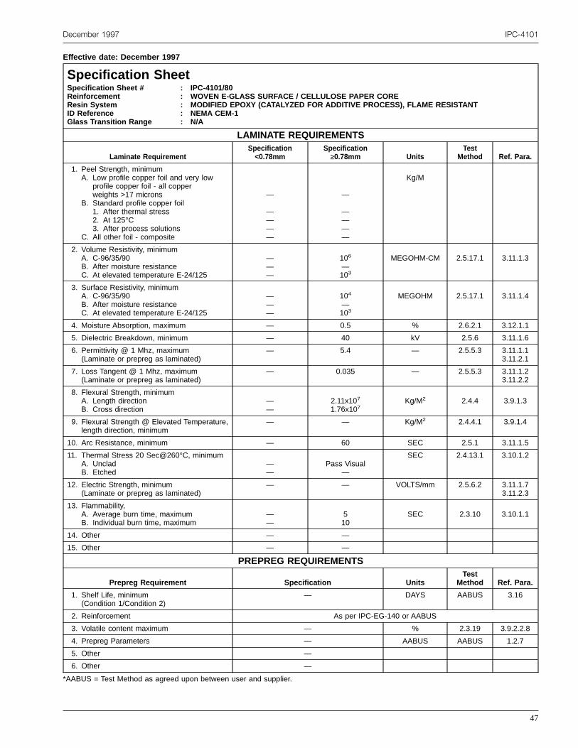
December 1997 IPC-4101
Effective date: December 1997
Specification SheetSpecification Sheet #ReinforcementResin SystemID ReferenceGlass Transition Range
: IPC-4101/80: WOVEN E-GLASS SURFACE / CELLULOSE PAPER CORE: MODIFIED EPOXY (CATALYZED FOR ADDITIVE PROCESS), FLAME RESISTANT: NEMA CEM-1: N/A
LAMINATE REQUIREMENTS
Laminate RequirementSpecification<0.78mm
Specification≥0.78mm Units
TestMethod Ref. Para.
1. Peel Strength, minimumA. Low profile copper foil and very low
profile copper foil - all copperweights >17 microns
B. Standard profile copper foil1. After thermal stress2. At 125°C3. After process solutions
C. All other foil - composite
—
————
—
————
Kg/M
2. Volume Resistivity, minimumA. C-96/35/90B. After moisture resistanceC. At elevated temperature E-24/125
———
106
—103
MEGOHM-CM 2.5.17.1 3.11.1.3
3. Surface Resistivity, minimumA. C-96/35/90B. After moisture resistanceC. At elevated temperature E-24/125
———
104
—103
MEGOHM 2.5.17.1 3.11.1.4
4. Moisture Absorption, maximum — 0.5 % 2.6.2.1 3.12.1.1
5. Dielectric Breakdown, minimum — 40 kV 2.5.6 3.11.1.6
6. Permittivity @ 1 Mhz, maximum(Laminate or prepreg as laminated)
— 5.4 — 2.5.5.3 3.11.1.13.11.2.1
7. Loss Tangent @ 1 Mhz, maximum(Laminate or prepreg as laminated)
— 0.035 — 2.5.5.3 3.11.1.23.11.2.2
8. Flexural Strength, minimumA. Length directionB. Cross direction
——
2.11x10⁷
1.76x10⁷Kg/M2 2.4.4 3.9.1.3
9. Flexural Strength @ Elevated Temperature,length direction, minimum
— — Kg/M2 2.4.4.1 3.9.1.4
10. Arc Resistance, minimum — 60 SEC 2.5.1 3.11.1.5
11. Thermal Stress 20 Sec@260°C, minimumA. UncladB. Etched
——
Pass Visual—
SEC 2.4.13.1 3.10.1.2
12. Electric Strength, minimum(Laminate or prepreg as laminated)
— — VOLTS/mm 2.5.6.2 3.11.1.73.11.2.3
13. Flammability,A. Average burn time, maximumB. Individual burn time, maximum
——
510
SEC 2.3.10 3.10.1.1
14. Other — —
15. Other — —
PREPREG REQUIREMENTS
Prepreg Requirement Specification UnitsTest
Method Ref. Para.
1. Shelf Life, minimum(Condition 1/Condition 2)
— DAYS AABUS 3.16
2. Reinforcement As per IPC-EG-140 or AABUS
3. Volatile content maximum — % 2.3.19 3.9.2.2.8
4. Prepreg Parameters — AABUS AABUS 1.2.7
5. Other —
6. Other —
*AABUS = Test Method as agreed upon between user and supplier.
47

IPC-4101 December 1997
Effective date: December 1997
Specification SheetSpecification Sheet #ReinforcementResin SystemID ReferenceGlass Transition Range
: IPC-4101/81: WOVEN E-GLASS FACE / NON-WOVEN GLASS CORE: EPOXY RESIN (CATALYZED FOR ADDITIVE PROCESS), FLAME RESISTANT: NEMA CEM-3: N/A
LAMINATE REQUIREMENTS
Laminate RequirementSpecification<0.78mm
Specification≥0.78mm Units
TestMethod Ref. Para.
1. Peel Strength, minimumA. Low profile copper foil and very low
profile copper foil - all copperweights >17 microns
B. Standard profile copper foil1. After thermal stress2. At 125°C3. After process solutions
C. All other foil - composite
—
————
—
————
Kg/M
2. Volume Resistivity, minimumA. C-96/35/90B. After moisture resistanceC. At elevated temperature E-24/125
———
106
—103
MEGOHM-CM 2.5.17.1 3.11.1.3
3. Surface Resistivity, minimumA. C-96/35/90B. After moisture resistanceC. At elevated temperature E-24/125
———
104
—103
MEGOHM 2.5.17.1 3.11.1.4
4. Moisture Absorption, maximum — 0.5 % 2.6.2.1 3.12.1.1
5. Dielectric Breakdown, minimum — 40 kV 2.5.6 3.11.1.6
6. Permittivity @ 1 Mhz, maximum(Laminate or prepreg as laminated)
— 5.4 — 2.5.5.3 3.11.1.13.11.2.1
7. Loss Tangent @ 1 Mhz, maximum(Laminate or prepreg as laminated)
— 0.035 — 2.5.5.3 3.11.1.23.11.2.2
8. Flexural Strength, minimumA. Length directionB. Cross direction
——
2.32x10⁷
1.90x10⁷Kg/M2 2.4.4 3.9.1.3
9. Flexural Strength @ Elevated Temperature,length direction, minimum
— — Kg/M2 2.4.4.1 3.9.1.4
10. Arc Resistance, minimum — 60 SEC 2.5.1 3.11.1.5
11. Thermal Stress 20 Sec@260°C, minimumA. UncladB. Etched
——
Pass Visual—
SEC 2.4.13.1 3.10.1.2
12. Electric Strength, minimum(Laminate or prepreg as laminated)
— — VOLTS/mm 2.5.6.2 3.11.1.73.11.2.3
13. Flammability,A. Average burn time, maximumB. Individual burn time, maximum
——
510
SEC 2.3.10 3.10.1.1
14. Other — —
15. Other — —
PREPREG REQUIREMENTS
Prepreg Requirement Specification UnitsTest
Method Ref. Para.
1. Shelf Life, minimum(Condition 1/Condition 2)
— DAYS AABUS 3.16
2. Reinforcement As per IPC-EG-140 or AABUS
3. Volatile content maximum — % 2.3.19 3.9.2.2.8
4. Prepreg Parameters — AABUS AABUS 1.2.7
5. Other —
6. Other —
*AABUS = Test Method as agreed upon between user and supplier.
48

December 1997 IPC-4101
Effective date: December 1997
Specification SheetSpecification Sheet #ReinforcementResin SystemID ReferenceGlass Transition Range
: IPC-4101/82: WOVEN E-GLASS: EPOXY RESIN (CATALYZED FOR ADDITIVE PROCESS), FLAME RESISTANT: NEMA FR-4: 110°C MINIMUM
LAMINATE REQUIREMENTS
Laminate RequirementSpecification<0.78mm
Specification≥0.78mm Units
TestMethod Ref. Para.
1. Peel Strength, minimumA. Low profile copper foil and very low
profile copper foil - all copperweights > 17 microns
B. Standard profile copper foil1. After thermal stress2. At 125°C3. After process solutions
C. All other foil - composite
—
————
—
————
Kg/M
2. Volume Resistivity, minimumA. C-96/35/90B. After moisture resistanceC. At elevated temperature E-24/125
106
—103
—106
103
MEGOHM-CM 2.5.17.1 3.11.1.3
3. Surface Resistivity, minimumA. C-96/35/90B. After moisture resistanceC. At elevated temperature E-24/125
104
—103
—104
103MEGOHM 2.5.17.1 3.11.1.4
4. Moisture Absorption, maximum 0.80 0.35 % 2.6.2.1 3.12.1.1
5. Dielectric Breakdown, minimum — 40 kV 2.5.6 3.11.1.6
6. Permittivity @ 1 Mhz, maximum(Laminate or prepreg as laminated)
5.4 5.4 — 2.5.5.3 3.11.1.13.11.2.1
7. Loss Tangent @ 1 Mhz, maximum(Laminate or prepreg as laminated)
0.035 0.030 — 2.5.5.3 3.11.1.23.11.2.2
8. Flexural Strength, minimumA. Length directionB. Cross direction
——
4.23x10⁷
3.52x10⁷Kg/M2 2.4.4 3.9.1.3
9. Flexural Strength @ Elevated Temperature,length direction, minimum
— — Kg/M2 2.4.4.1 3.9.1.4
10. Arc Resistance, minimum 60 60 SEC 2.5.1 3.11.1.5
11. Thermal Stress 10 Sec@288°C, minimumA. UncladB. Etched
Pass Visual—
Pass Visual—
SEC 2.4.13.1 3.10.1.2
12. Electric Strength, minimum(Laminate or prepreg as laminated)
2.90x10⁴ — VOLTS/mm 2.5.6.2 3.11.1.73.11.2.3
13. Flammability,A. Average burn time, maximumB. Individual burn time, maximum
510
510
SEC 2.3.10 3.10.1.1
14. Other — —
15. Other — —
PREPREG REQUIREMENTS
Prepreg Requirement Specification UnitsTest
Method Ref. Para.
1. Shelf Life, minimum(Condition 1/Condition 2)
— MONTHS AABUS 3.16
2. Reinforcement As per IPC-EG-140 or AABUS
3. Volatile content maximum — % 2.3.19 3.9.2.2.8
4. Prepreg Parameters — AABUS AABUS 1.2.7
5. Other —
6. Other —
*AABUS = Test Method as agreed upon between user and supplier.
49
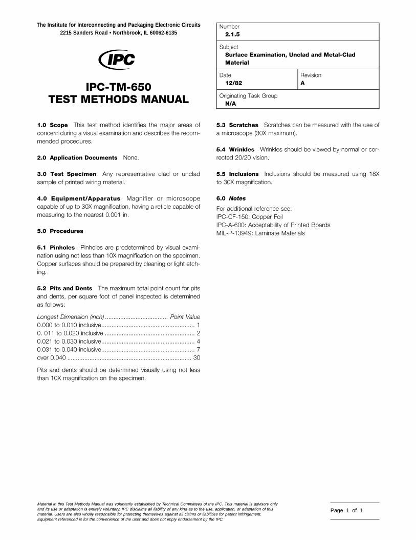
1.0 Scope This test method identifies the major areas ofconcern during a visual examination and describes the recom-mended procedures.
2.0 Application Documents None.
3.0 Test Specimen Any representative clad or uncladsample of printed wiring material.
4.0 Equipment/Apparatus Magnifier or microscopecapable of up to 30X magnification, having a reticle capable ofmeasuring to the nearest 0.001 in.
5.0 Procedures
5.1 Pinholes Pinholes are predetermined by visual exami-nation using not less than 10X magnification on the specimen.Copper surfaces should be prepared by cleaning or light etch-ing.
5.2 Pits and Dents The maximum total point count for pitsand dents, per square foot of panel inspected is determinedas follows:
Longest Dimension (inch) ..................................... Point Value0.000 to 0.010 inclusive....................................................... 10. 011 to 0.020 inclusive ..................................................... 20.021 to 0.030 inclusive....................................................... 40.031 to 0.040 inclusive....................................................... 7over 0.040 ......................................................................... 30
Pits and dents should be determined visually using not lessthan 10X magnification on the specimen.
The Institute for Interconnecting and Packaging Electronic Circuits2215 Sanders Road • Northbrook, IL 60062-6135
IPC-TM-650TEST METHODS MANUAL
Material in this Test Methods Manual was voluntarily established by Technical Committees of theand its use or adaptation is entirely voluntary. IPC disclaims all liability of any kind as to the use,material. Users are also wholly responsible for protecting themselves against all claims or liabilitieEquipment referenced is for the convenience of the user and does not imply endorsement by the
5.3 Scratches Scratches can be measured with the use ofa microscope (30X maximum).
5.4 Wrinkles Wrinkles should be viewed by normal or cor-rected 20/20 vision.
5.5 Inclusions Inclusions should be measured using 18Xto 30X magnification.
6.0 Notes
For additional reference see:IPC-CF-150: Copper FoilIPC-A-600: Acceptability of Printed BoardsMIL-P-13949: Laminate Materials
Number2.1.5
SubjectSurface Examination, Unclad and Metal-CladMaterial
Date12/82
RevisionA
Originating Task GroupN/A
IPC. This material is advisory onlyapplication, or adaptation of thiss for patent infringement.IPC.
Page 1 of 1
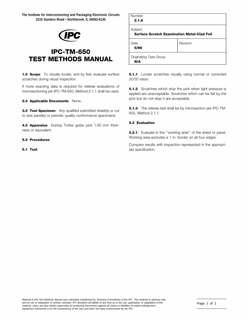
1.0 Scope To visually locate, and by feel, evaluate surfacescratches during visual inspection.
If more exacting data is required for referee evaluations ofmicrosectioning per IPC-TM-650, Method 2.1.1 shall be used.
2.0 Applicable Documents None.
3.0 Test Specimen Any qualified submitted sheet(s) or cutto size panel(s) or periodic quality conformance specimens.
4.0 Apparatus Dunlop Tortex guitar pick 1.00 mm thick-ness or equivalent.
5.0 Procedures
5.1 Test
The Institute for Interconnecting and Packaging Electronic Circuits2215 Sanders Road • Northbrook, IL 60062-6135
IPC-TM-650TEST METHODS MANUAL
Material in this Test Methods Manual was voluntarily established by Technical Committees of thand its use or adaptation is entirely voluntary. IPC disclaims all liability of any kind as to the usematerial. Users are also wholly responsible for protecting themselves against all claims or liabiliEquipment referenced is for the convenience of the user and does not imply endorsement by th
5.1.1 Locate scratches visually using normal or corrected20/20 vision.
5.1.2 Scratches which stop the pick when light pressure isapplied are unacceptable. Scratches which can be felt by thepick but do not stop it are acceptable.
5.1.3 The referee test shall be by microsection per IPC-TM-650, Method 2.1.1.
5.2 Evaluation
5.2.1 Evaluate in the ‘‘working area’’ of the sheet or panel.Working area excludes a 1 in. border on all four edges.
Compare results with inspection represented in the appropri-ate specification.
Number2.1.9
SubjectSurface Scratch Examination Metal-Clad Foil
Date5/86
Revision
Originating Task GroupN/A
e IPC. This material is advisory only, application, or adaptation of thisties for patent infringement.e IPC.
Page 1 of 1

1.0 Scope This inspection method is designed to visuallyinspect for dicyandiamide, commonly called ‘‘dicy,’’ that is notdissolved in the resin of prepreg materials in which it is usedas a curing agent, by means of polarized lighting.
2.0 Applicable Documents None.
3.0 Test Specimens Unless otherwise specified, one ply ofprepreg cut to 101.6 x 101.6 mm [4.0 x 4.0 in].
4.0 Apparatus or Material
4.1 An incidental light source such as a photographic lightbox, light table or illuminated microscope base. Light intensityshall be sufficient to detect small features of the specimenunder fully polarized conditions, such as a 60 watt light bulbused in a light box.
4.2 A matched pair of polarizing filter lens.
4.3 A microscope capable of magnification at least 30X to100X.
5.0 Procedure
5.1 Preparation
5.1.1 Place one polarizing filter directly over the light source.Place the specimen over the filter.
5.1.2 Place second polarizing filter over the specimendirectly in line with the first filter.
5.1.3 Set microscope to desired magnification between 30Xand 100X and position over the approximate center of the fil-ters. For referee purposes, magnification shall be at 100X.
5.1.4 Focus microscope on the specimen through the topfilter.
5.1.5 Rotate top filter 90° from bottom filter (see Figure 1).
5.2 Evaluation
5.2.1 Examine for the presence of dicy over the entire speci-men, excluding the edges. The dicy (if present) will causescattering of the polarized light which can then pass throughthe second filter in sufficient intensity to be visible.
The Institute for Interconnecting and Packaging Electronic Circuits2215 Sanders Road • Northbrook, IL 60062-6135
IPC-TM-650TEST METHODS MANUAL
Material in this Test Methods Manual was voluntarily established by Technical Committees of thand its use or adaptation is entirely voluntary. IPC disclaims all liability of any kind as to the usematerial. Users are also wholly responsible for protecting themselves against all claims or liabiliEquipment referenced is for the convenience of the user and does not imply endorsement by th
5.2.2 Careful scrutiny must be used to eliminate consider-ation of dust or cracks in the resin as dicy, because they willalso diffuse polarized light. Severe incidence of undissolveddicy may be observed using partially or non-polarized light.
5.3 Report Presence of dicy shall be noted as per thedegrees shown in Appendix A. Appearance as to the form,i.e., crystal, flake, or cluster, shall be reported.
6.0 Notes
6.1 Dicy is a curing agent used with epoxy resin; it is intro-duced at the resin mixing stage. If the mix is not homoge-neous or is improperly done, particles of dicy may not dissolveor may be recrystallized. Dicy may also recrystallize during thetreating operation. During lamination of the prepreg, dicy maycontribute to the formation of voids or other defects.
6.2 Dicy Flake A loose mass of crystals, usually in the formof crystals radiating from a center point.
6.3 Dicy Cluster A concentration of crystals or flakes.
Figure 1 Dicy inspection set-up (expanded view)
Number2.1.10
SubjectVisual Inspection for Undissolved Dicyandiamide
Date12/94
RevisionA
Originating Task GroupMIL-P-13949 Test Methods Task Group (7-11b)
e IPC. This material is advisory only, application, or adaptation of thisties for patent infringement.e IPC.
Page 1 of 3
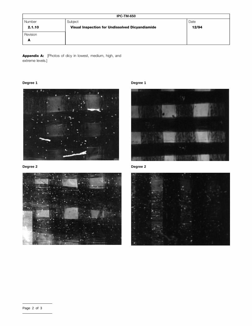
IPC-TM-650
Number
2.1.10
Subject
Visual Inspection for Undissolved Dicyandiamide
Date
12/94
Revision
A
Appendix A: [Photos of dicy in lowest, medium, high, andextreme levels.]
Degree 1
Degree 2
Page 2 of 3
Degree 1
Degree 2

IPC-TM-650
Number
2.1.10
Subject
Visual Inspection for Undissolved Dicyandiamide
Date
12/94
Revision
A
A
Degree 3Degree 4
Degree 4
DEGREES OF DICYANDI
Degree 2Degree 4
Degree 5
MIDE (DICY) CRYSTALS
Page 3 of 3

1.0 Scope This method is designed to determine dimen-sional conformance to specification of production-cut panelsof laminate or prepreg for length, width, and perpendicularity.
2.0 Applicable Documents
IPC-PC-90
3.0 Test Specimens
3.1 Size Production cut panels in the dimensions intendedfor shipment shall be used.
3.2 Sampling Sampling rates shall be in accordance withthe applicable specification. (Also see 6.1.)
4.0 Apparatus or Material Unless otherwise specified,precision of measurement apparatus shall be in accordancewith the applicable specification.
4.1 Vernier calipers capable of measuring up to 914 ± 6.4mm [36.0 ± 0.25 in] or equivalent.
4.2 Tape measure capable of measuring up to 1829 mm[72.0 in]
4.3 Carpenters square, or equivalent
4.4 Pin gauges, dial indicators or equivalent
5.0 Procedure
5.1 Length Measure the length of the edges of the panelthat are parallel to the grain direction using a vernier caliper.
5.2 Width Measure the length of the edges of the panelthat are perpendicular to the grain direction using a verniercaliper.
5.3 Perpendicularity
5.3.1 Method A: by diagonals
5.3.1.1 Measure the diagonals of the panel using verniercaliper or tape measure.
The Institute for Interconnecting and Packaging Electronic Circuits2215 Sanders Road • Northbrook, IL 60062
IPC-TM-650TEST METHODS MANUAL
Material in this Test Methods Manual was voluntarily established by Technical Committees of thand its use or adaptation is entirely voluntary. IPC disclaims all liability of any kind as to the usmaterial. Users are also wholly responsible for protecting themselves against all claims or liabilEquipment referenced is for the convenience of the user and does not imply endorsement by t
5.3.1.2 Calculate perpendicularity as follows:D = D1–D2 (Maximum allowable difference in diagonals)
Where:
D1 = √(L + T)2 + W2
D2 = √(L − T)2 + W2
L = Nominal length of panel [ins]
W = Nominal width of panel [ins]
Tii = Tolerance in inches per inch for perpendicularityshown in the procurement document.
T = Tii x W (Tolerance in inches)
5.3.1.3 Calculate the actual difference in the diagonals fromthe measurements taken.
5.3.1.4 Compare the actual difference to the allowablemaximum.
5.3.2 Method B: By carpenters square (‘‘Right Angle’’Square)
5.3.2.1 Place the panel in the carpenters square, contactingthe square by at least two corners.
5.3.2.2 Using suitable means (see 4.4) measure the dis-tance of the panel’s corner that does not contact the square.
5.3.2.3 Calculate the perpendicularity by dividing the dis-tance by the length of the longest dimension of the panel.
5.4 Evaluation Compare the measurements with dimen-sional requirements of the applicable specification. Record thenumber of panels that do not comply. Record the number ofnoncomplying panels for each dimension—length, width, andperpendicularity.
5.5 Report the number of panels, specifying which dimen-sion, that do not comply with the applicable specification.
6.0 Notes
6.1 Sampling may also be determined by IPC-PC-90 onmaterials produced by continuous processing.
Number2.2.19.1
SubjectLength, Width and Perpendicularity of Laminateand Prepreg Panels
Date12/94
Revision
Originating Task GroupMIL-P-13949 Test Methods Task Group (7-11b)
e IPC. This material is advisory onlye, application, or adaptation of thisities for patent infringement.he IPC.
Page 1 of 1

1.0 Scope This method evaluates the chemical cleanabilityof metal-clad laminate surfaces of oxidation and anti-oxidationprotective coatings.
2.0 Applicable Document None.
3.0 Test Specimen The size of the test specimen shall bedetermined by the post etching tests to be performed.
4.0 Apparatus
4.1 Standard conveyorized spray cleaning modules or suit-able laboratory equipment.
4.2 Personal safety equipment needed to perform this testare as follows: rubber or polyethylene gloves, plastic or coatedapron and safety goggles.
4.3 Chemicals
4.3.1 Method A—Sodium Persulfate
Chemical Concentration Temperature
Cleaner/Degreaser
Per manufacturer’srecommended limits
As recommended
SodiumPersulfate
1.5 lbs/gal(± 0.5 lb/gal)
100° ± 5°F(38° ± 3°C)
4.3.2 Method B—Ammonium Persulfate
Chemical Concentration Temperature
Cleaner/Degreaser
Per manufacturer’srecommended limits
As recommended
AmmoniumPersulfateTech Grade
2.0 lbs/gal(± 0.5 lb/gal)
100°F Max
The Institute for Interconnecting and Packaging Electronic Circuits2215 Sanders Road • Northbrook, IL 60062-6135
IPC-TM-650TEST METHODS MANUAL
Material in this Test Methods Manual was voluntarily established by Technical Committees of thand its use or adaptation is entirely voluntary. IPC disclaims all liability of any kind as to the usmaterial. Users are also wholly responsible for protecting themselves against all claims or liabilEquipment referenced is for the convenience of the user and does not imply endorsement by t
5.0 Procedure
5.1 Specimen Preparation Shear the material to therequired specimen size and remove the rough edges from thespecimen by sanding or other suitable means.
5.2 Cleaning
5.2.1 Conveyorized Spray Cleaning Process the speci-men through the conveyorized modules at a speed which willpermit 30 ± 5 seconds of exposure to the micro etching solu-tion. Rinse specimens with deionized water for 1-2 minutesafter micro etching.
5.2.2 Laboratory Cleaning Place the specimen in acleaner/degreaser solution and gently agitate for 30 ± 5 sec-onds. Remove the specimen and flush with tap water. Nextplace the specimen in a micro etch solution for 30 ± 5 sec-onds and vigorously agitate. Remove the specimen and flushwith deionized water for 1-2 minutes.
5.3 Surface Evaluation The metal cladding on the testspecimen shall be cleaned to a uniform matte finish. Deionizedor distilled water poured on the metal surface does not beador form puddles.
6.0 Notes
6.1 Sodium persulfate solution shall be replaced if the cop-per concentration exceeds 3.0 oz/gal (22.5 gal).
6.2 Solution spray from nozzles should be checked for uni-formity across the specimen.
Number2.3.1.1
SubjectChemical Cleaning of Metal-Clad Laminate
Date5/86
RevisionB
Originating Task GroupN/A
e IPC. This material is advisory onlye, application, or adaptation of thisities for patent infringement.he IPC.
Page 1 of 1

1.0 Scope This method is designed to evaluate the resis-tance of dielectric materials to organic chemicals representa-tive of those used in printed board fabrication and assembly.It is intended to provide a distinction between materials ofvarying chemical resistance and, when applicable, an indica-tion of the degree of cure.
2.0 Applicable Documents
IPC-TM-650
Method 2.2.18, Determination of Thickness of Laminates byMechanical Measurement
Weast, R.C., CRC Handbook of Chemistry and Physics, 65thEdition, E-37, 1984
3.0 Test Specimens
3.1 Number Unless otherwise specified, three specimensshall be used.
3.2 Size Unless otherwise specified, specimen shall be50.8 x 50.8 mm ± 0.5 mm [2.0 x 2.0 ± 0.02 in] by the thick-ness of the material (see 5.1, Preparation). Edges shall besmooth, whether by the cutting procedure, or by sanding, orother means.
3.3 Location Specimen may be cut from anywhere in thesheet of material, except no specimens shall be taken closerthan 25.4 mm [1.0 in] from any edge as laminated.
4.0 Apparatus or Material
4.1 Analytical balance with a draft shield and .001 gram orbetter resolution.
4.2 Air circulating oven, capable of 105 ± 2°C [221 ± 3.6°F].
4.3 Desiccator capable of maintaining an atmosphere of lessthan 30% relative humidity at 23°C [73°F]. See 6.2.5
4.4 Cutting apparatus such as diamond saw, shear papercutter or router.
4.5 Edge smoothing apparatus such as 400 grit or finersandpaper.
The Institute for Interconnecting and Packaging Electronic Circuits2215 Sanders Road • Northbrook, IL 60062-6135
IPC-TM-650TEST METHODS MANUAL
Material in this Test Methods Manual was voluntarily established by Technical Committees of theand its use or adaptation is entirely voluntary. IPC disclaims all liability of any kind as to the use,material. Users are also wholly responsible for protecting themselves against all claims or liabilitEquipment referenced is for the convenience of the user and does not imply endorsement by the
4.6 One liter battery jar, with cover.
4.7 Metal tongs or forceps.
4.8 Metal rack (to support specimens vertically).
4.9 Metal support (e.g., mounting clip used for microsec-tioning).
4.10 Laminating press capable of the specified temperatureand pressure.
4.11 Timer: 1 hour with 1 second resolution.
4.12 Timer: 60 seconds, 1 second resolution.
4.13 Solvent: Methylene Chloride, Reagent Grade or HPLCGrade. MC recovered by distillation back to reagent grademay be used. HPLC Grade shall be used for referee pur-poses.
4.14 Prepreg (for single sided laminate and coated foil testonly).
4.15 Copper foil, 1 oz./ft2 treated (for prepreg tests only).
4.16 Ventilation hood
4.17 Micrometer, capable of measuring to within 0.025 mm[0.001 in]
4.18 Water bath at 23 ± 0.5°C [73 ± 0.9°F].
4.19 Thermometer capable of measuring to within 0.1°Cresolution.
4.20 Etching system capable of metallic cladding removal.
5.0 Procedure
5.1 Sample Preparation
5.1.1 Single-sided Laminate Single-sided laminate lessthan 0.5 mm [0.020 in] shall be laminated together with theclad surfaces facing out. Two plies minimum of prepreg shallbe used. The prepreg shall be of the same basic resin type
Number2.3.4.2
SubjectChemical Resistance of Laminates, Prepreg, andCoated Foil Products, by Solvent Exposure
Date12/94
RevisionA
Originating Task GroupMIL-P-13949 Test Methods Task Group (7-11b)
IPC. This material is advisory onlyapplication, or adaptation of this
ies for patent infringement.IPC.
Page 1 of 4

IPC-TM-650
Number2.3.4.2
SubjectChemical Resistance of Laminates, Prepreg, and Coated FoilProducts, by Solvent Exposure
Date12/94
RevisionA
and of a thickness when cured not greater than 0.13 mm[0.005 in] total, using the prepreg manufacturer’s recom-mended press cycle. Laminate over 0.5 mm [0.020 in] shall betreated like double clad laminate without lamination.
5.1.2 Resin-coated Foil Resin-coated foil samples shallbe laminated together using at least two plies of prepregbetween the coated sides of the foil. The prepreg shall be ofthe same basic resin type and of a thickness when cured notgreater than 0.127 mm [0.005 in] total, using a press cycleand any subsequent post cure which meets the manufactur-er’s recommendations for both the coated foil and prepreg.(See 6.2.1.1)
For qualification and referee tests, a 0.50 ± 0.10 mm [0.02 in]composite core is to be built.
5.1.3 Laminate with Coated Foil Surfaces Single-sidedlaminate shall be tested after lamination as in 5.1.1. Double-sided laminate with coated foil on one side shall have the foiletched from the uncoated side and shall subsequently belaminated as 5.1.1. Double-sided laminate with coated foil onboth sides shall be tested as is.
5.1.4 Prepreg Prepreg shall be laminated to a thickness of0.50 ± 0.10 mm [0.020 in] using treated copper foil on bothsides and following the prepreg manufacturer’s recommendedpress and post cure cycle. (See 6.2.1.1) For prepreg less than0.13 mm [0.005 in] thick when cured, at least two plies shallbe bonded to either side of an etched laminate of a thicknesssuch that the pressed sample satisfies the required thickness.
5.1.5 Double-sided Laminate Double-sided laminate shallbe submitted for testing as is.
5.2 Specimen Preparation
5.2.1 Etching Samples, as specified in 3.0, shall be etchedin accordance with standard industry practices. For refereepurposes, 2.3.6, 2.3.7, 2.3.7.1, or 2.3.7.2 shall be used.
5.2.2 Cut the specimens to size per 3.2. Cutting shall beperformed using apparatus and in such a manner that pre-vents edge damage. Edge smoothing is recommended toprevent excessive absorption.
5.2.3 Markings Each specimen shall be identified by mark-ing with a lead pencil or equivalent technique which is notremoved by the solvent and which doesn’t affect the results.
Page 2 of 4
5.3 Preconditioning
5.3.1 Measure and record nominal thickness of the testspecimen using IPC-TM-650, Method 2.2.18.
5.3.2 Place the etched specimens vertically in the metalrack and dry the specimens in the oven for 60 ± 5 minutes at105°C [221°F]. Air flow around each specimen must beassured.
5.3.3 Remove the specimens from the oven and immedi-ately place in the desiccator to cool for 60 ± 30 minutes.
5.4 Test Condition The test shall be performed at stan-dard laboratory conditions: 23 ± 2°C [73 ± 0.9°F] and 50 ± 5%R.H.
5.5 Measurement
5.5.1 Fill the battery jar with 750 ml of solvent and maintainthe solvent temperature at 23 ± 0.5°C [73 ± 0.9°] using thewater bath.
5.5.2 Remove the specimens individually from the desicca-tor and weigh to the nearest milligram on the analytical bal-ance. Samples must be weighed within 60 seconds ofremoval from the desiccator. Record these weights as W1.
5.5.3 Place the rack into the beaker of solvent, start the 60minute timer and using tongs place the specimens in the rackat suitable intervals (recommend approximately 2 minutes).Insure that the specimens are completely immersed.
5.5.4 Place the metal clip on the balance and tare it out.
5.5.5 After 10 minutes +15, –0 seconds, using the tongsremove the first specimen from the solvent and start the 60second timer.
5.5.6 Slowly wag the specimen in the air. As soon as thespecimen is free of surface wetness, but no longer than 30seconds, place the specimen on the balance supporting it onthe metal clip such that both surfaces of the specimen areexposed (placing the specimen flat on the balance pan is notpermitted since evaporation from the side next to the pan willbe reduced.)

IPC-TM-650
Number2.3.4.2
SubjectChemical Resistance of Laminates, Prepreg, and Coated FoilProducts, by Solvent Exposure
Date12/94
RevisionA
5.5.7 After 60 +5, –0 seconds from the time of removal fromthe solution, note the weight of the specimen and record it asW2.
5.5.8 Repeat 5.5.5 – 5.5.7 for the remaining specimensinsuring the immersion time of each specimen is kept withinthe tolerance.
5.5.9 A fresh batch of solvent shall be used for no morethan 18 specimens or for a period of time no longer than 8hours.
5.6 Evaluation
5.6.1 Weight Gain
5.6.1.1 Subtract the dry weight of each specimen, W1, fromthe final weight, W2 of each specimen after immersion.Record the weight gain in mg.
5.6.1.2 Calculate the average weight gain in mg.
5.6.2 Appearance Examine the specimens using 20/20vision for any changes to the appearance of the material, suchas hazing, whitening or swelling.
5.7 Report
5.7.1 Report the average weight gain in milligrams for thematerial tested.
5.7.2 Report the measured specimen thickness.
5.7.3 Report actual test conditions for temperature andhumidity and the solvent temperature.
5.7.4 Report any anomalies in the test or any variations fromthe specified procedures or tolerances.
5.7.5 Report any changes in the visual quality of the speci-mens as determined in 5.6.2.
6.0 Notes
6.1 Safety Considerations See the MSDS sheet for thesolvent used before running this test.
6.1.1 During test, the beaker with the test solvent should becovered or under a ventilation hood.
6.1.2 Dispose of the spent solvent in accordance with localregulations.
6.2 Factors Affecting Tests
6.2.1 Sample
6.2.1.1 Same Sample The results obtained on the samesheet of material may be significantly affected by the degreeof cure of the material and the thermal history of the sample.
6.2.1.2 Variation Due to Thickness of Sample There is avery small difference due to sample thickness. This is under10% on typical epoxy materials for 0.2 mm [0.008 in] to 1.5mm [0.060 in] and under 5% on more chemical resistantmaterial from 0.13 mm [0.005 in] to 1.5 mm [0.060 in].
6.2.2 Accuracy Since there are no standards for this typeof test, the accuracy of the method cannot be established.
6.2.3 Precision the reproducibility of this test depends onthe degree of control over the controlled variables and someother variables such as atmospheric pressure, which are gen-erally not controlled in industrial laboratories. Precisionbetween laboratories with 20% to 50% RH was 10% at the 90mg level and 16% at the 25 mg level.
6.2.4 Desiccants Desiccants capable of 0.002 mg mois-ture levels include P205, Mg (C104) 2, anhydrous BaO andfused KOH.
Some other desiccants such as CaCl2 result in considerablyhigher moisture levels and may not be used in this test. (SeeWeast R.C., CRC Handbook of Chemistry and Physics, 65thedition, E–37, 1984.)
6.2.5 Humidity Considerations
6.2.5.1 Effect of Humidity Higher humidity will producehigher solvent pickup due to retarded solvent evaporation.
6.2.5.2 Control of Humidity Control of the critical environ-ment can be obtained in uncontrolled laboratories using anenclosed balance with a saturated salt solution of Mg(No3)2,6H20 (for 50% RH).
All significant openings in the enclosure are sealed with tapeand an inner door is fabricated with a small opening forsample entry and exit. A shallow pan is fabricated to occupymost of the balance floor without contacting the weighing
Page 3 of 4
IPC-TM-650
Number2.3.4.2
SubjectChemical Resistance of Laminates, Prepreg, and Coated FoilProducts, by Solvent Exposure
Date12/94
RevisionA
pan. If the balance door is closed immediately after sampleentry and exit, 50 ± 5% RH can be maintained.
Verification of conditions in the enclosure during a simulatedtest can be made using a rapid response humidity probe;however, this should be done with unconditioned specimenssince solvents will affect the response of many humidityprobes.
6.2.6 Temperature Considerations The effect of the sol-vent temperature on results is severe. A variation of 5°C [9°F]can result in an error as high as 50% relative to values deter-mined at 23°C [73°F].
6.3 Consideration of Other Test Parameters
6.3.1 Using Same Solvent Shorter dwell times, e.g., 3minutes, generally result in better discrimination betweenmaterial of varying chemical resistance. However, test variabil-ity is generally increased. Shorter tests are excellent for sideby side comparisons of materials.
Page 4 of 4
Longer tests, e.g., 30 minutes, often do not differentiateadequately between materials, and while useful on homoge-neous material, variability on material with surface coatingsmay be excessive.
6.3.2 Other Solvent Blends Other solvents and variousmethylene chloride based combinations have been commonlyused in the industry. However, results and precision of the testmay vary significantly and the added problem of variability insolution make-up is introduced.
6.4 Supercession This test method supersedes 2.3.4.2,dated 5/86, and 2.3.4.3, dated 5/86.
6.5 Desiccator Conditions The Test Methods Task Groupdetermined that a great majority of test laboratories are unableto consistently hold the Relative Humidity in a desiccator toless than 20%. Based on data from participating company labmanagement, the lowest practically feasible RH for use withthe affected IPC Test Methods is 30% maximum.
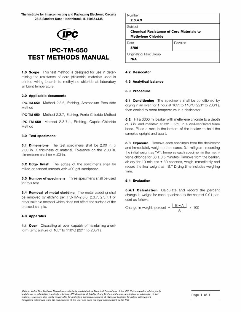
1.0 Scope This test method is designed for use in deter-mining the resistance of core (dielectric) materials used inprinted wiring boards to methylene chloride at laboratoryambient temperature.
2.0 Applicable documents
IPC-TM-650 Method 2.3.6, Etching, Ammonium PersulfateMethod
IPC-TM-650 Method 2.3.7, Etching, Ferric Chloride Method
IPC-TM-650 Method 2.3.7,1, Etching, Cupric ChlorideMethod
3.0 Test specimens
3.1 Dimensions The test specimens shall be 2.00 in. x2.00 in. X thickness of material. Tolerance on the 2.00 in.dimensions shall be ± .03 in.
3.2 Edge finish The edges of the specimens shall bemilled or sanded smooth with 400 grit sandpaper.
3.3 Number of specimens Three specimens shall be usedfor this test.
3.4 Removal of metal cladding The metal cladding shallbe removed by etching per IPC-TM-2.3.6, 2.3.7, 2.3.7.1 orother suitable method which does not affect the surface of thepressed sample.
4.0 Apparatus
4.1 Oven Circulating air oven capable of maintaining a uni-form temperature of 105° to 110°C (221° to 230°F).
The Institute for Interconnecting and Packaging Electronic Circuits2215 Sanders Road • Northbrook, IL 60062-6135
IPC-TM-650TEST METHODS MANUAL
Material in this Test Methods Manual was voluntarily established by Technical Committees of thand its use or adaptation is entirely voluntary. IPC disclaims all liability of any kind as to the usmaterial. Users are also wholly responsible for protecting themselves against all claims or liabilEquipment referenced is for the convenience of the user and does not imply endorsement by t
4.2 Desiccator
4.3 Analytical balance
5.0 Procedure
5.1 Conditioning The specimens shall be conditioned bydrying in an oven for 1 hour at 105° to 110°C (221° to 230°F),then cooled to room temperature in a desiccator.
5.2 Fill a 3000 ml beaker with methylene chloride to a depthof 3 in. and maintain at 23° ± 2°C in a well-ventilated fumehood. Place a rack in the bottom of the beaker to hold thesamples upright and apart.
5.3 Exposure Remove each specimen from the desiccatorand immediately weigh to the nearest 0.1 milligram, recordingthe initial weight as ‘‘A’’. Immerse each specimen in the meth-ylene chloride for 30 ± 0.5 minutes. Remove from the beaker,air dry for 10 minutes ± 30 seconds, weigh immediately andrecord the final weight as ‘‘B.’’ Drying time includes weighingtime.
5.4 Evaluation
5.4.1 Calculation Calculate and record the percentchange in weight for each specimen to the nearest 0.01 per-cent as follows:
Change in weight, percent = | B − A |A
x 100
Number2.3.4.3
SubjectChemical Resistance of Core Materials toMethylene Chloride
Date5/86
Revision
Originating Task GroupN/A
e IPC. This material is advisory onlye, application, or adaptation of thisities for patent infringement.he IPC.
Page 1 of 1

1.0 Scope To determine the quality of the dielectric mate-rial after etching with ammonium persulfate.
2.0 Applicable Document None.
3.0 Test Specimen Specimen 2 in. x 2 in. X thickness ofone ounce or two ounces copper clad.
4.0 Apparatus
4.1 Heated Electrical Equipment for etching the speci-men.
4.2 Air Circulating Chamber capable of maintaining 80°C ±3°C (176°F).
4.3 Equipment and Chemicals needed to perform this testare as follows: Rubber or polyethylene gloves, lint-free cloth,grade FFF pumice and plastic scrubbing brushes, distilledwater, 10% solution oxalic acid, ammonium persulfate solu-tion, methylethyl ketone, toluol, and trichlorethylene.
5.0 Procedure
5.1 Preparation of Specimen Remove rough edges fromthe specimen by sanding or other suitable means.
5.2 Etching Etch specimen with vigorous agitation for theminimum time in 66° BAUME ammonium persulfate solutionmonitored at 43°C ± 3° (109.4°F). After removal of the copper,immediately wash the specimen with running tap water for 2to 5 minutes and keep the specimen from drying until the
The Institute for Interconnecting and Packaging Electronic Circuits2215 Sanders Road • Northbrook, IL 60062-6135
IPC-TM-650TEST METHODS MANUAL
Material in this Test Methods Manual was voluntarily established by Technical Committees of tand its use or adaptation is entirely voluntary. IPC disclaims all liability of any kind as to the usmaterial. Users are also wholly responsible for protecting themselves against all claims or liabEquipment referenced is for the convenience of the user and does not imply endorsement by
specimen is placed in the chamber. Immerse the specimensin a 10% solution of oxalic acid in distilled water 25°C ± 8°(77°F) for 15 to 20 minutes providing gentle circulation of theoxalic acid solution during this period. Flush the specimenwith tap water for 2 to 5 minutes, then scrub the specimenswith pumice to remove resist. Wipe the resist off with a lint freecloth moistened with a suitable solvent. Scrub the specimenwith a plastic bristled brush under running tap water for 2 to 5minutes. Rinse the specimen again in distilled water.
5.3 Condition Dry the specimens for 1 hour in a chambermaintained at 80°C (176°F). If specimens are for electricaltests, handle only with rubber or polyethylene gloves.
5.4 Evaluation of Test Examine specimens for whitedeposits or other surface contaminants, loss of surface resin,softness, delaminations, blistering or measling. Clad speci-mens also should be evaluated for blisters or delamination ofthe copper foil.
6.0 Notes
6.1 If the etching time exceeds 15 minutes for 1 ounce cop-per or 30 minutes for 2 ounces copper, renew the etchingsolution.
6.2 Oxalic acid is very toxic and extreme care should beexercised.
6.3 The time to produce a clean pattern with a minimum ofundercutting is approximately 7 minutes for 1 ounce copperand 15 minutes for 2 ounces copper, using fresh solution.
Number2.3.6
SubjectEtching Ammonium Persulfate Method
Date7/75
RevisionA
Originating Task GroupN/A
he IPC. This material is advisory onlye, application, or adaptation of thisilities for patent infringement.the IPC.
Page 1 of 1
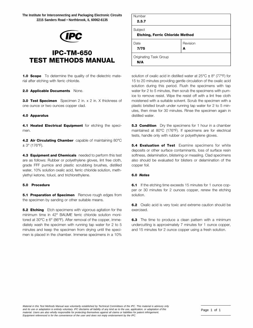
1.0 Scope To determine the quality of the dielectric mate-rial after etching with ferric chloride.
2.0 Applicable Documents None.
3.0 Test Specimen Specimen 2 in. x 2 in. X thickness ofone ounce or two ounces copper clad.
4.0 Apparatus
4.1 Heated Electrical Equipment for etching the speci-men.
4.2 Air Circulating Chamber capable of maintaining 80°C± 3° (176°F).
4.3 Equipment and Chemicals needed to perform this testare as follows: Rubber or polyethylene gloves, lint free cloth,grade FFF pumice and plastic scrubbing brushes, distilledwater, 10% solution oxalic acid, ferric chloride solution, meth-ylethyl ketone, toluol, and trichlorethylene.
5.0 Procedure
5.1 Preparation of Specimen Remove rough edges fromthe specimen by sanding or other suitable means.
5.2 Etching Etch specimens with vigorous agitation for theminimum time in 42° BAUME ferric chloride solution moni-tored at 30°C ± 6° (86°F). After removal of the copper, imme-diately wash the specimen with running tap water for 2 to 5minutes and keep the specimen from drying until the speci-men is placed in the chamber. Immerse specimens in a 10%
The Institute for Interconnecting and Packaging Electronic Circuits2215 Sanders Road • Northbrook, IL 60062-6135
IPC-TM-650TEST METHODS MANUAL
Material in this Test Methods Manual was voluntarily established by Technical Committees of thand its use or adaptation is entirely voluntary. IPC disclaims all liability of any kind as to the usmaterial. Users are also wholly responsible for protecting themselves against all claims or liabilEquipment referenced is for the convenience of the user and does not imply endorsement by t
solution of oxalic acid in distilled water at 25°C ± 8° (77°F) for15 to 20 minutes providing gentle circulation of the oxalic acidsolution during this period. Flush the specimens with tapwater for 2 to 5 minutes, then scrub the specimens with pum-ice to remove resist. Wipe the resist off with a lint free clothmoistened with a suitable solvent. Scrub the specimen with aplastic bristled brush under running tap water for 2 to 5 min-utes, then rinse for 30 minutes. Rinse the specimen again indistilled water.
5.3 Condition Dry the specimens for 1 hour in a chambermaintained at 80°C (176°F). If specimens are for electricaltests, handle only with rubber or polyethylene gloves.
5.4 Evaluation of Test Examine specimens for whitedeposits or other surface contaminants, loss of surface resinsoftness, delamination, blistering or measling. Clad specimensalso should be evaluated for blisters or delamination of thecopper foil.
6.0 Notes
6.1 If the etching time exceeds 15 minutes for 1 ounce cop-per or 30 minutes for 2 ounces copper, renew the etchingsolution.
6.2 Oxalic acid is very toxic and extreme caution should beexercised.
6.3 The time to produce a clean pattern with a minimumundercutting is approximately 7 minutes for 1 ounce copper,and 15 minutes for 2 ounce copper using a fresh solution.
Number2.3.7
SubjectEtching, Ferric Chloride Method
Date7/75
RevisionA
Originating Task GroupN/A
e IPC. This material is advisory onlye, application, or adaptation of thisities for patent infringement.he IPC.
Page 1 of 1

1.0 Scope This method is a means for preparation of testspecimens for determination of bare dielectric material qualityand properties, using cupric chloride as the etching solutionfor removal of copper cladding.
2.0 Applicable Documents
IPC-TM-650Method 2.3.1.1, Chemical Cleaning of Metal Clad Laminate
3.0 Test Specimens The size of lot samples or test speci-mens shall be determined by the inspections or tests to beperformed after etching and the capabilities of the etchingequipment.
4.0 Apparatus or Material
4.1 Standard chemical etching chamber or laboratoryequipment suitable to the etchant chemistry.
4.2 Air circulating oven capable of maintaining the specifiedtemperatures and tolerances.
4.3 Personal safety equipment shall include: rubber or poly-ethylene gloves, plastic or coated apron and safety goggles.
4.4 ChemicalsChemical Concentration
Cupric Chloride, CuCl2-2H20 0.54 kg/l 4.5 lb/gal
Hydrochloric Acid, HCl 9.3% by weight (3N)25% by volume
Distilled/Deionized Water As required
Sodium Hydroxide, NaOH 10% by weight
Reagent grade isopropyl alcohol(IPA) As required
4.5 Pattern Developing Materials Etch resist system ormaterials capable of producing the applicable conductor pat-terns.
5.0 Procedure
5.1 Preparation of Specimen
The Institute for Interconnecting and Packaging Electronic Circuits2215 Sanders Road • Northbrook, IL 60062-6135
IPC-TM-650TEST METHODS MANUAL
Material in this Test Methods Manual was voluntarily established by Technical Committees of thand its use or adaptation is entirely voluntary. IPC disclaims all liability of any kind as to the usmaterial. Users are also wholly responsible for protecting themselves against all claims or liabilEquipment referenced is for the convenience of the user and does not imply endorsement by t
5.1.1 Shear the material to the appropriate sample or speci-men size and if necessary remove the rough edges from thespecimen by sanding or other suitable means. Specimensmay be chemically cleaned in accordance with IPC-TM-650,Method 2.3.1.1. Specimens may also be mechanicallycleaned.
5.1.2 If a conductor pattern is required, prepare the materialby applying etch resist according to standard industry prac-tices.
5.2 Etching
5.2.1 Remove the metal cladding by etching in a spraychamber or other suitable container containing 30-32*BAUME cupric chloride solution maintained at 51.7 ± 5.6°C[125 ± 10°F]. Etching time shall be minimized to prevent over-exposure of the bare laminate material to the etching solutionand yet allow for complete removal of the exposed metal clad-ding. If the specimens are etched in a laboratory environment,vigorous agitation may be required.
5.2.2 Rinse the specimens thoroughly.
5.2.3 For referee purposes, neutralize any residual etchantby quickly dipping in a 10% solution of NaOH solution andthen rinse thoroughly with distilled or deionized water. Note: Ifthis step is not followed, undercutting of the circuitry is pos-sible, which in time could lead to inaccurate test data, such aslow peel strength.
5.3 Cleaning
5.3.1 If etch resist has been used, samples shall have theresist or tape removed by standard industry practices.
5.3.2 When electrical testing is required on the material, donot allow the etched specimens to dry before they go throughthe cleaning process. For general testing, scrubbing with asoft natural bristle brush under running tap water and rinsingwith distilled water or deionized water may be adequate. Forcritical testing and for referee testing, laminates shall besoaked for 10 minutes in reagent grade IPA followed immedi-ately by a 10 minute rinse in flowing 16 megaohm deionizedwater.
Number2.3.7.1
SubjectCupric Chloride Etching Method
Date12/94
RevisionA
Originating Task GroupMIL-P-13949 Test Methods Task Group (7-11b)
e IPC. This material is advisory onlye, application, or adaptation of thisities for patent infringement.he IPC.
Page 1 of 2

IPC-TM-650
Number2.3.7.1
SubjectCupric Chloride Etching Method
Date12/94
RevisionA
5.4 Drying Samples may be air dryed for subsequent mate-rial evaluations. For referee testing, an oven bake for 1 hour at80 ± 5.6°C [176 ± 10°F] is required.
5.5 Evaluation Determine and record whether the etchingprocedure resulted in any unusual events, such as:
a. Dwell time in etcher necessary for complete copperremoval, if longer than normal.
b. Warpage or distortion of the material.
c. Discoloration or other visual changes to the material.
6.0 Notes None
Page 2 of 2

1.0 Scope This test method is designed to determine thedegree of flame resistance of metal-clad or unclad laminate. Itis intended for use on laminate of thicknesses 0.51 mm [0.020in] and greater.
2.0 Applicable Documents
IPC-TM-650
Method 2.3.6, Etching, Ammonium Persulfate MethodMethod 2.3.7, Etching, Ferric Chloride MethodMethod 2.3.7.1, Cupric Chloride Etching MethodMethod 2.3.7.2, Alkaline EtchingUL-STD-94, Flammability
3.0 Test Specimens
3.1 Size Test specimens shall be 127± 0.64 mm [5.0 ±0.025 in] in length and 12.7 ± 0.51 mm [0.5 ± 0.020 in] inwidth by the thickness being tested. Edges shall be smoothedafter cutting; any radius imparted to the corners shall notexceed 1.27 mm [0.05 in].
3.2 Quantity and Sampling Specimens may be taken par-allel to either grain direction, unless otherwise specified. Fivespecimens shall be prepared for each condition required.Reserve sets of five specimens should also be prepared in theevent a retest is necessary.
4.0 Apparatus or Material
4.1 Test Chamber A laboratory hood, totally enclosed,with a heat-resistance glass window for observing the test,shall be used. The exhaust fan shall be turned off during thetest, but may be turned on periodically to clear out the fumesbetween tests.
4.2 Specimen Holder Clamping device adjustable for ver-tical positioning of the test specimen shall be provided withinthe test chamber so that the specimen will hang with its lengthin a vertical position approximately coincident with the centralvertical axis of the test chamber.
4.3 Laboratory burner A Bunsen or Tirrill Burner shall beused having a tube length of 101.6 mm [4.0 in] and an insidediameter of 9.4 mm [0.370 in]. The burner shall not be
The Institute for Interconnecting and Packaging Electronic Circuits2215 Sanders Road • Northbrook, IL 60062-6135
IPC-TM-650TEST METHODS MANUAL
Material in this Test Methods Manual was voluntarily established by Technical Committees of thand its use or adaptation is entirely voluntary. IPC disclaims all liability of any kind as to the usematerial. Users are also wholly responsible for protecting themselves against all claims or liabiliEquipment referenced is for the convenience of the user and does not imply endorsement by th
equipped with end attachments.
4.4 Gas supply The gas supply shall be regulated andmetered for uniform flow. The standard gas shall be TechnicalGrade methane. Natural gas or other fuel gases such asbutane, propane and acetylene may be used, provided theyhave a nominal heat content of 1000 BTU per cubic foot.Technical grade methane shall be used for referee testing.
4.5 Timer Stopwatch or other suitable timing device with aprecision of 0.5 seconds minimum.
4.6 Desiccator Desiccation chamber capable of maintain-ing an atmosphere of less than 30% RH at 23°C [73°F].
4.7 Conditioning oven of circulating draft type capable ofmaintaining 125 ± 2°C [257 ± 3.6°F].
4.8 Thin steel scale or template for gauging flame height.
4.9 Etching system capable of removing metal-claddingfrom the laminate.
4.10 Cutting and edge smoothing apparatus such asshears, diamond blade saw, or other equipment, and sandingor routing equipment for smoothing.
5.0 Procedure
5.1 Specimen Preparation Metal-clad laminates shall becompletely etched using standard industry practices (see IPC-TM-650, Methods 2.3.7, 2.3.7.1, or 2.3.7.2). Unclad lami-nates shall be tested in the as-is condition. Specimens shallbe cut to size and the edges smoothed, in accordance with3.1.
5.2 Specimen Conditioning
5.2.1 Specimen sets shall be conditioned prior to testing byexposure to standard laboratory conditions of 23 ± 2°C[73 ± 3.6°F] and relative humidity of 50 ± 5% for 24 hoursminimum.
5.2.2 If specified, a second set of specimens shall beconditioned for 24 ± 2 hours at a temperature of 125 ± 2°C
Number2.3.10
SubjectFlammability of Laminate
Date12/94
RevisionB
Originating Task GroupMIL-P-13949 Test Methods Task Group (7-11b)
e IPC. This material is advisory only, application, or adaptation of thisties for patent infringement.e IPC.
Page 1 of 3

IPC-TM-650
Number2.3.10
SubjectFlammability of Laminate
Date12/94
RevisionB
[257 ± 3.6°F], then cooled in a desiccator for 4 hours mini-mum prior to testing.
5.2.3 Reserve sets of specimens may also be conditionedconcurrently for failure verification purposes.
5.3 Preparation for Testing
5.3.1 Adjustment of Test Flame The burner is ignited andadjusted to produce a blue flame 19 mm [0.75 in] high. Thecorrect flame is obtained by adjusting the gas supply and theair ports of the burner until a blue flame with a yellow- tippedouter cone 19 mm [0.75 in] high is produced. The air supplyis increased slightly by opening the air ports only until the yel-low tip just disappears and completely blue inner and outerflame cones are formed. The flame is remeasured for correctheight. The procedure is repeated as necessary until all con-ditions are met. The burner tube is vertical during adjustmentand testing. (See 6.2, 6.3, and 6.4.)
5.3.2 Specimen Mounting Each specimen is mounted inthe test fixture with its longitudinal axis vertical. The clampused shall cover no more than the upper 6.4 mm [0.25 in] ofthe specimen. The vertical position of the test fixture/specimen assembly is adjusted so that the lower end of thespecimen is 9.5 mm [0.375 in] above the top of the burnertube.
5.4 Measurement
5.4.1 The test flame is placed centrally under the lower endof the specimen for 10 ± 0.5 seconds. The burner is with-drawn from the specimen. If active combustion ceases priorto the specimen being completely consumed, the test flame isto be immediately placed under the specimen for an additional10 ± 0.5 seconds, then withdrawn as before.
5.4.2 Evaluation and Report Steps 5.5.1, 5.5.2, and5.5.3 shall be performed for each test condition.
5.5 Recording Data The following data is to be observedand recorded.
5.5.1 Duration of specimen burning to the nearest secondafter the first test flame application for each specimen.
5.5.2 Duration of specimen burning to the nearest secondafter the second test flame application for each specimen.
Page 2 of 3
5.5.3 Duration of specimen burning plus glowing to thenearest second after the second test flame application foreach specimen, only if required by the specification.
5.5.4 If any specimen burns up to the holding clamp on anyignition.
5.6 Calculation
5.6.1 Calculate the total specimen burning time and theaverage burning time based on ten ignitions per set of fivespecimens.
5.6.2 Calculation of the glowing time for each specimen, ifrequired by the specification.
5.7 Report The material shall be reported as out of compli-ance for one or more of the following test results, unless oth-erwise specified.
5.7.1 More than one specimen per set burns up to the hold-ing clamp on any ignition.
5.7.2 More than one specimen per set burns for a period oftime longer than allowed by the specification for a singlespecimen.
5.7.3 The total specimen burning time or the average speci-men burning time as applicable exceeds the maximumallowed by the specification and is beyond the tolerancespecified in 5.5.4.
5.7.4 More than one specimen glows for a period of timegreater than allowed by the specification (when applicable).
5.8 Retest If only one specimen per set fails to comply withthe requirements, the reserve set of specimens shall betested. In the case of total or average specimen burning time,the reserve set shall be tested only if these calculated valuesexceed the specification maximum by five seconds or less. Allspecimens from the reserve set shall comply with the require-ments.
6.0 Notes
6.1 Most laminates covered by this test method do not dripmolten or flaming material, and therefore provisions for this evalu-ation have not been described. If necessary, refer to UL-STD-94.
6.2 The inside of the burner barrel should be cleaned fre-quently. Specimen combustion by-products can collectaround and inside the barrel tip. These deposits can be

IPC-TM-650
Number2.3.10
SubjectFlammability of Laminate
Date12/94
RevisionB
flushed out during burner ignition and flame adjustment resultingin a false yellow flame tip. Proper flame adjustment becomes verydifficult.
6.3 When the flame is correct and the specimens end is atthe proper height above the burner 9.5 mm [0.375 in], theinner blue come of the flame will just meet the end of thespecimen. The specimen will then be ignited by the hottestarea of the flame.
6.4 Accurate centering of the flame under the specimen isessential for consistent testing.
6.5 Desiccator Conditions The Test Methods Task Groupdetermined that a great majority of test laboratories are unableto consistently hold the Relative Humidity in a desiccator toless than 20%. Based on data from participating company labmanagement, the lowest practically feasible RH for use withthe affected IPC Test Methods is 30% maximum.
Page 3 of 3
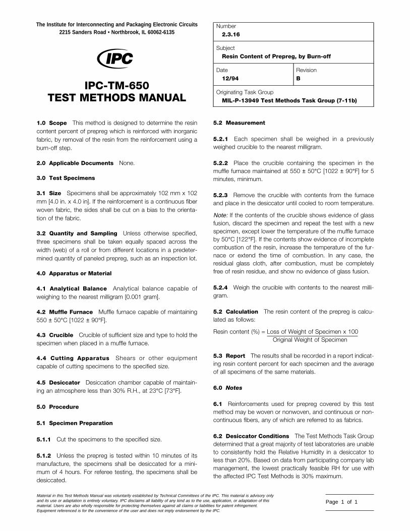
1.0 Scope This method is designed to determine the resincontent percent of prepreg which is reinforced with inorganicfabric, by removal of the resin from the reinforcement using aburn-off step.
2.0 Applicable Documents None.
3.0 Test Specimens
3.1 Size Specimens shall be approximately 102 mm x 102mm [4.0 in. x 4.0 in]. If the reinforcement is a continuous fiberwoven fabric, the sides shall be cut on a bias to the orienta-tion of the fabric.
3.2 Quantity and Sampling Unless otherwise specified,three specimens shall be taken equally spaced across thewidth (web) of a roll or from different locations in a predeter-mined quantity of paneled prepreg, such as an inspection lot.
4.0 Apparatus or Material
4.1 Analytical Balance Analytical balance capable ofweighing to the nearest milligram [0.001 gram].
4.2 Muffle Furnace Muffle furnace capable of maintaining550 ± 50°C [1022 ± 90°F].
4.3 Crucible Crucible of sufficient size and type to hold thespecimen when placed in a muffle furnace.
4.4 Cutting Apparatus Shears or other equipmentcapable of cutting specimens to the specified size.
4.5 Desiccator Desiccation chamber capable of maintain-ing an atmosphere less than 30% R.H., at 23°C [73°F].
5.0 Procedure
5.1 Specimen Preparation
5.1.1 Cut the specimens to the specified size.
5.1.2 Unless the prepreg is tested within 10 minutes of itsmanufacture, the specimens shall be desiccated for a mini-mum of 4 hours. For referee testing, the specimens shall bedesiccated.
The Institute for Interconnecting and Packaging Electronic Circuits2215 Sanders Road • Northbrook, IL 60062-6135
IPC-TM-650TEST METHODS MANUAL
Material in this Test Methods Manual was voluntarily established by Technical Committees of thand its use or adaptation is entirely voluntary. IPC disclaims all liability of any kind as to the usematerial. Users are also wholly responsible for protecting themselves against all claims or liabiliEquipment referenced is for the convenience of the user and does not imply endorsement by th
5.2 Measurement
5.2.1 Each specimen shall be weighed in a previouslyweighed crucible to the nearest milligram.
5.2.2 Place the crucible containing the specimen in themuffle furnace maintained at 550 ± 50°C [1022 ± 90°F] for 5minutes, minimum.
5.2.3 Remove the crucible with contents from the furnaceand place in the desiccator until cooled to room temperature.
Note: If the contents of the crucible shows evidence of glassfusion, discard the specimen and repeat the test with a newspecimen, except lower the temperature of the muffle furnaceby 50°C [122°F]. If the contents show evidence of incompletecombustion of the resin, increase the temperature of the fur-nace or extend the time of combustion. In any case, theresidual glass cloth, after combustion, must be completelyfree of resin residue, and show no evidence of glass fusion.
5.2.4 Weigh the crucible with contents to the nearest milli-gram.
5.2 Calculation The resin content of the prepreg is calcu-lated as follows:
Resin content (%) = Loss of Weight of Specimen x 100Original Weight of Specimen
5.3 Report The results shall be recorded in a report indicat-ing resin content percent for each specimen and the averageof all specimens of the same materials.
6.0 Notes
6.1 Reinforcements used for prepreg covered by this testmethod may be woven or nonwoven, and continuous or non-continuous fibers, any of which are referred to as fabrics.
6.2 Desiccator Conditions The Test Methods Task Groupdetermined that a great majority of test laboratories are unableto consistently hold the Relative Humidity in a desiccator toless than 20%. Based on data from participating company labmanagement, the lowest practically feasible RH for use withthe affected IPC Test Methods is 30% maximum.
Number2.3.16
SubjectResin Content of Prepreg, by Burn-off
Date12/94
RevisionB
Originating Task GroupMIL-P-13949 Test Methods Task Group (7-11b)
e IPC. This material is advisory only, application, or adaptation of thisties for patent infringement.e IPC.
Page 1 of 1

1.0 Scope This method is designed to determine the resincontent of a prepreg without removing the resin from the rein-forcement. The basis weight of the fabric must be known. Thismethod is applicable to both organic and inorganic reinforce-ments.Note: For referee testing of prepregs with inorganic reinforce-ment, Method 2.3.16 shall be used.
2.0 Applicable Documents
IPC-EG-140 Specification for Finished Fabric Woven from‘‘E’’ Glass for Printed Boards
IPC-SG-141 Specification for Finished Fabric Woven from‘‘S’’ Glass
IPC-A-142 Specification for Finished Fabric Woven from Ara-mid for Printed Boards
IPC-QF-143 Specification for Finished Fabric Woven fromQuartz (Pure Fused Silica) for Printed Boards
IPC-TM-650
Method 2.1.6.1, Weight of Fabric Reinforcements
Method 2.3.17, Resin Flow Percent of Prepreg
Method 2.3.19, Volatile Content of Prepreg Materials
3.0 Test Specimens
3.1 Size Specimens shall be 101.6 mm x 101.6 mm [4.0 inx 4.0 in]. If the reinforcement is a continuous fiber woven fab-ric, the sides shall be cut on a bias to the orientation of thefabric.
3.2 Quality and Sampling Unless otherwise specified,three specimens shall be taken equally spaced across thewidth (web) of a roll or from different locations in a predeter-mined quantity of paneled prepreg, such as an inspection lot.If specimens are to be used for Resin Flow Percent (TM2.3.17), then four specimens shall be used, cut from adjacentpoints in a roll or cut panels (see 6.4).
4.0 Apparatus or Material
4.1 Analytical balance, capable of weighing to the nearestmilligram (0.001 gram).
The Institute for Interconnecting and Packaging Electronic Circuits2215 Sanders Road • Northbrook, IL 60062-6135
IPC-TM-650TEST METHODS MANUAL
Material in this Test Methods Manual was voluntarily established by Technical Committees of thand its use or adaptation is entirely voluntary. IPC disclaims all liability of any kind as to the usematerial. Users are also wholly responsible for protecting themselves against all claims or liabiliEquipment referenced is for the convenience of the user and does not imply endorsement by th
4.2 Static shield (a thin piece of metal, e.g., 7 oz./sq. ft.copper foil 5 in x 5 in (127 mm x 127 mm) or larger). This isnot needed if the balance pan is larger than the specimen.
4.3 Sample cutting apparatus—die cut press, or equivalent,capable of cutting specimens to the specified size.
4.4 Desiccator capable of maintaining an atmosphere lessthan 30% R.H. at 23°C [73°F].Note: Do not use vacuum or other means which would becapable of removing solvent or resin fractions.
5.0 Procedure
5.1 Preconditioning Unless the prepreg is tested within 10minutes of production the specimen shall be desiccated for aminimum of 4 hours. For referee testing, the specimens shallbe desiccated.
5.2 Test Conditions The test shall be performed at stan-dard laboratory conditions. For materials which absorb mois-ture rapidly, care should be taken to insure that moisture con-tent is not significant by measurement immediately afterremoval from desiccation.
5.3 Measurement
5.3.1 Place the static shield on the balance pan.
5.3.2 Zero the balance.
5.3.3 If applicable, remove the specimens from the desicca-tor. Place the specimens together on the balance, insuringthat they sit entirely on the balance pan, or the static shield ifneeded (see 6.4).
5.3.4 Determine and record the weight of the specimens tothe nearest 0.1g. For prepregs of nominal 0.15 mm [0.006 in]thickness and less, weigh to the nearest 0.001g.
5.4 Calculations
5.4.1 Determine the basis weight of the fabric using one ofthe methods of Appendix A.
Number2.3.16.1
SubjectResin Content of Prepreg, by Treated Weight
Date12/94
RevisionC
Originating Task GroupMIL-P-13949 Test Methods Task Group (7-11b)
e IPC. This material is advisory only, application, or adaptation of thisties for patent infringement.e IPC.
Page 1 of 2

IPC-TM-650
Number2.3.16.1
SubjectResin Content of Prepreg, by Treated Weight
Date12/94
RevisionC
5.4.2 Calculate the Resin Content (RC) of the material fromthe treated weight (TW) and the basis weight (BW) of the fab-ric for 41,290 mm2 [64 in2 ]. The basis weight may be deter-mined by any suitable method in Appendix A.
RC = (1 − BWTW) x 100
where:RC = Resin Content in %BW = weight of the fabric as determined in accordance
with Appendix ATW = treated weight from 5.3.4.
5.5 Report
5.5.1 Report the Resin Content to the nearest .1%.
5.5.2 Report the method used to determine the basisweight of the reinforcement.
5.5.3 Report any anomalies in the test or any variations fromthe specified procedures or tolerances
6.0 Notes
6.1 The solvent or volatile content of the prepreg (excludingmoisture) is considered part of the treated weight using thismethod. If it is desired to exclude solvent content, the speci-men should be vacuumed for an appropriate time and tem-perature.
6.2 The accuracy of this method for determination of resincontent is dependent primarily upon the accuracy of the basisweight and the consistency of the reinforcement.
6.3. The effect of static charges may present a serious prob-lem in weighing material which has been stored if the sampleis larger than the sample pan.
6.4 If it is desired to check variation across the web the indi-vidual specimens may be weighed separately or 4 specimensmay be cut down the web at each location to be tested.
6.5 Desiccator Conditions The Test Methods Task Groupdetermined that a great majority of test laboratories are unableto consistently hold the Relative Humidity in a desiccator toless than 20%. Based on data from participating company labmanagement, the lowest practically feasible RH for use withthe affected IPC Test Methods is 30% maximum.
Page 2 of 2
Appendix A
Determination of Basis Weight of Reinforcement All thefollowing methods consider any finishes applied to the fabricas part of the fabric. In most cases, the level of organic mate-rial is negligible; however, special considerations have to bemade for material such as greige goods, which have substan-tial amount of organic (5% or more), and for organic fabricswhich may have significant moisture content.
Methods shown are based on four specimens, with a totalarea of 41,290 mm2 [64.0 in2].
Method 1 Determine the Basis Weight from the actuallength, width and weight of the roll.
BW = 806.4 WRL x W
BW = Basis Wt in gWR = Roll weight in lb.L = Roll length in yds.W = Roll width in in.
Method 2 Determine the Basis Weight from median statisti-cal or typical fabric weight in oz/yd2
BW = 1.40 WBW = Basis wt in gW = Weight of 1 yd2 in oz.
Method 3 Determine the Basis Weight from the actual fab-ric weight at the beginning of the roll, using Method 2.1.6.1.
Method 4 Determine the Basis Weight from the reportedweight supplied by the manufacturer.
BW = 1.40WBW = Basis Wt in gW = Weight of 1 yd2 in oz
Method 5 Determine the Basis Weight by consulting the unitweight tables in the applicable documents; see 2.0.

1.0 Scope This method is designed for determining thetreated weight of a specific area of prepreg. Treated weight isan alternative to Resin Content Percent as a means of deter-mining the usability and functionality of prepreg. This methodis applicable to both organic and inorganic reinforcements buteffective use of this technique requires knowledge of resin andreinforcement specific gravity, as well as basis weight of thereinforcement.
2.0 Applicable Documents
IPC-EG-140 Specification for Finished Fabric Woven From‘‘E’’ Glass for Printed Board
IPC-SG-141 Specification for Finished Fabric Woven From‘‘S’’ Glass
IPC-A-142 Specification for Finished Fabric Woven FromAramid for Printed Boards
IPC-QF-143 Specification for Finished Fabric Woven FromQuartz (Pure Fused Silica) for Printed Boards
IPC-TM-650
Method 2.4.38, Prepreg Scaled Flow TestingMethod 2.3.16, Resin Content of Prepreg by Burn-off
3.0 Test Specimens
3.1 Size The prepreg specimen shall be two or more diecut plies. Each ply shall be 140 ± 0.25 mm [5.5 ± 0.01 in] by178 ± 0.25 mm [7.0 ± 0.01 in]. Use of the specimen for scaledflow test (IPC-TM-650, Method 2.4.38) is recommended. See2.4.38 for additional criteria.
Alternate specimen sizes such as 102 mm x 102 mm [4 in x4 in] or 457 mm x 610 mm [18 in x 24 in] are acceptable byagreement between supplier and user.
3.2 Quantity and Sampling Unless otherwise specified,three specimens shall be taken from the lot at randomlyselected locations, whether taken from a roll or from precutpanels. Specimens shall be taken from the fabric roll (as sup-plied by the manufacturer) no closer to the selvage (or cutedge) than a distance equal to one-tenth of the width of theroll.
4.0 Apparatus or Material
The Institute for Interconnecting and Packaging Electronic Circuits2215 Sanders Road • Northbrook, IL 60062-6135
IPC-TM-650TEST METHODS MANUAL
Material in this Test Methods Manual was voluntarily established by Technical Committees of theand its use or adaptation is entirely voluntary. IPC disclaims all liability of any kind as to the use,material. Users are also wholly responsible for protecting themselves against all claims or liabilitEquipment referenced is for the convenience of the user and does not imply endorsement by the
4.1 Analytical balance capable of weighing to the nearest0.001g.
4.2 Static shield (a thin piece of metal, e.g., 7 oz copper foilat least 25.4 mm [1.0 in] larger in length and width than theprepreg specimen). This is not required if the balance pan islarger than the specimen.
4.3 Sample cutting press with die 140 ± 0.25 mm x 178 ±0.25 mm [5.50 ± 0.01 in x 7.00 ± 0.01 in].
4.4 Kraft paper or equivalent back up material for cuttingpress.
4.5 Desiccator capable of maintaining an atmosphere lessthan 30% R.H. at 23°C [73°F].
5.0 Procedure
5.1 Specimen Preparation
5.1.1 Cut the specimens to the specified size and configu-ration, see 3.1.
5.1.2 Preconditioning Unless the prepreg is tested within10 minutes of production, the specimen shall be desiccatedfor a minimum of 4 hours. For referee testing, the specimensshall be desiccated.
5.2 Test Conditions The test shall be performed at stan-dard laboratory conditions. For materials which absorb mois-ture rapidly, care should be taken to insure that moisture con-tent is not significant by measurement immediately afterremoval from desiccation.
5.3 Equipment Setup Place the static shield on the bal-ance pan and zero the balance.
5.4 Measurement
5.4.1 Place each specimen on the balance, ensuring that itsits entirely on the static shield.
5.4.2 Determine and record the treated weight of each speci-men to the nearest 0.001g.
Number2.3.16.2
SubjectTreated Weight of Prepreg
Date12/94
Revision
Originating Task GroupMIL-P-13949 Test Methods Task Group (7-11b)
IPC. This material is advisory onlyapplication, or adaptation of this
ies for patent infringement.IPC.
Page 1 of 2

IPC-TM-650
Number2.3.16.2
SubjectTreated Weight of Prepreg
Date12/94
Revision
5.5 Report
5.5.1 Average the individual specimen weight and report theaverage per ply treated weight to the nearest 0.001g per 25.4sq mm [1.0 sq in] .
6.0 Notes
6.1 The volatile content of the prepreg (excluding moisture)is considered part of the treated weight using this method. Ifit is desired to exclude volatile content, the specimen shouldbe baked for an appropriate time and temperature.
6.2 The effect of static charges may present a serious prob-lem in weighing material if the specimen size is greater thanthe sample pan.
6.3 If it is desired to check variation across or along theweb, individual specimens should be taken from the locationin question.
6.4 If it is desirable to check the weight uniformity ofthe reinforcement, this can be done by burn-off similar to IPC-TM-650, Method 2.3.16, if inorganic.
6.5 Calculations Treated weight can be used to specifyand/or predict prepreg thickness and resin content. Equationsto calculate thickness and resin content for woven fabric ‘‘E’’-glass reinforced epoxy FR-4 prepreg are given below. Thecalculations assume a resin specific gravity of 1.37 gr/cc andan ‘‘E’’-Glass specific gravity of 2.59 gr/cc.
Woven ‘‘E’’-glass fabric nominal dry weights and tolerancesare assumed the values given in IPC-EG-140. The nominaldry weights and tolerances for other reinforcements, suchas ‘‘S’’ glass, woven aramid, and quartz fabric, can befound in IPC-SG-141, IPC-A-142, IPC-QF-143. Appropriatevalues for the specific gravities of other resins and rein-forcements and the basis weights of other reinforcementsare the responsibility of the vendor or can be negotiatedbetween vendor and user. Inorganic reinforcement basisweight can be measured as given in 6.4.
Page 2 of 2
6.5.1 Resin Content The resin content can be calculatedfrom the average per ply treated weight and the measured ornominal unit glass fabric weight. Conversely, the treatedweight can be calculated from the resin content. Equations tocalculate both are shown below:
RC = (1 − BWTW) x 100
TW = BW1 – (RC/100)
Where:RC = resin content by weightTW = treated weight (weight per area per ply)BW = unit basis weight (weight per area per ply)
6.5.2 Prepreg Thickness The average prepreg thicknesscan be calculated using the average per ply treated weightand the measured or nominal unit glass fabric weight. Equa-tions to calculate prepreg thickness for Scaled Flow test sizedspecimens (38.5 square inches per ply) are given below:Ingeneral:
H0 = 1.585TW – 1.585Wf (df – dr)dr df dr
For ‘‘E’’-glass reinforced FR-4 epoxy prepreg:Ho = 1.157 TW – 0.545 Wf
Where:Ho = prepreg thickness (mils per ply)TW = treated weight (weight per 38.5 sq in per ply)Wf = unit glass fabric weight (weight per 38.5 sq in per
ply)dr = resin density (grams per cubic centimeter)df = fabric fiber density (grams per cubic centimeter)
6.6 Desiccator Conditions The Test Methods Task Groupdetermined that a great majority of test laboratories are unableto consistently hold the Relative Humidity in a desiccator toless than 20%. Based on data from participating company labmanagement, the lowest practically feasible RH for use withthe affected IPC Test Methods is 30% maximum.

1.0 Scope This test method is designed to measure theResin Flow Percent by weight in prepreg.
2.0 Applicable Documents None
3.0 Test Specimens
3.1 Size and Configuration A specimen shall consist ofmultiple plies of prepreg cut 102 ± 0.25 mm [4.0 ± 0.010 in]by 102 ± 0.25 mm [4.0 ± 0.010 in]. If the reinforcement is acontinuous fiber woven fabric, the sides shall be cut on a biasto the fabric weave. Unless otherwise specified, the testspecimen shall have four plies. (Note: an alternative specimenconfiguration commonly used is a stack that weighs approxi-mately 20 g.)
3.2 Quantity and Sampling Unless otherwise specified,the number of specimens tested shall be as follows: for quali-fication testing, 3 specimens shall be tested with the piecesfor each specimen taken from areas of the prepreg that rep-resents the center and both sides of the material as impreg-nated. For lot testing, one specimen shall be tested, with thepieces randomly taken. Pieces shall be taken no closer to theselvage (or cut edge) than a distance equal to one-tenth of thewidth of the roll.
4.0 Apparatus or Material
4.1 Laminating Press Unless otherwise specified, laminat-ing press capable of maintaining a temperature of 171 ± 3°C[340 ± 5°F] and capable of providing a pressure of 1380 ± 70kPa [200 ± 10 psi] on the test specimen (see 6.1).
4.2 Analytical Balance Analytical balance capable ofweighing to the nearest 0.001 gram.
4.3 Plates Caul plates approximately 3.2 mm [0.125 in]thick and at least 152 mm x 152 mm [6.0 in x 6.0 in], but nolarger than the press platen size, and made from type 304steel, or equivalent.
4.4 Circle Punch A punch or die set capable of cutting acircle 81.1 mm [3.192 in] in diameter.
4.5 Desiccator Desiccation chamber capable of maintain-
The Institute for Interconnecting and Packaging Electronic Circuits2215 Sanders Road • Northbrook, IL 60062-6135
IPC-TM-650TEST METHODS MANUAL
Material in this Test Methods Manual was voluntarily established by Technical Committees of thand its use or adaptation is entirely voluntary. IPC disclaims all liability of any kind as to the usematerial. Users are also wholly responsible for protecting themselves against all claims or liabiliEquipment referenced is for the convenience of the user and does not imply endorsement by th
ing an atmosphere of less than 30% R.H. at 23°C [73°F].
4.6 Release Material The release material shall be Tedlar,Type MR, (polyvinyl fluoride, PVF) or equivalent, cut at least aslarge as the caul plates.
5.0 Procedure
5.1 Specimen Preparation
5.1.1 The prepreg shall be cut to conform with the speci-men size and configuration, see 3.1.
5.1.2 For referee purposes only, specimens shall be desic-cated for a minimum of 4 hours.
5.2 Measurement
5.2.1 Determine the weight of each specimen to the nearest0.005 gram. Record this as the original weight, or Wo.
5.2.2 Stack the plies of prepreg for one specimen with thegrain of the cloth aligned in the same direction and placebetween two pieces of release film. Place this packagebetween two caul plates that are at room temperature.
5.2.3 Place specimen and caul plates in a preheated lami-nating press maintained at the specified temperature andimmediately apply pressure such that the specified pressure isachieved within 5 seconds after press closure. Unless other-wise specified, the temperature shall be 171 ± 3°C [340 ± 5°F]and the pressure shall be 200 ± 10 psi [1380 ± 70 kPa].
5.2.4 Maintain the specified pressure for 10 + 6, – 0minutes.
5.2.5 Open press, remove specimen, and allow to cool toroom temperature.
5.2.6 If applicable, post cure the test specimen in accor-dance with the manufacturer’s post cure method (in order toprevent specimen damage by cutting).
5.2.7 Using the punch and die set, remove a circular discmeasuring 81.1 mm [3.192 in] in diameter from the center ofthe specimen.
Number2.3.17
SubjectResin Flow Percent of Prepreg
Date8/97
RevisionD
Originating Task GroupMIL-P-13949 Test Methods Task Group (7-11b)
e IPC. This material is advisory only, application, or adaptation of thisties for patent infringement.e IPC.
Page 1 of 2

IPC-TM-650
Number2.3.17
SubjectResin Flow Percent of Prepreg
Date8/97
RevisionD
5.2.8 Weigh the circular specimen on the analytical balanceto the nearest 0.005 gram. Record this as the disc weight, orWD.
5.3 Calculation The resin flow is calculated as follows:
Resin Flow, Percent = (WO − 2 WD
WO) x 100
Wo = Original weight of the specimenWD = Disc weight of the specimen (cut from the specimen
after pressing)
5.4 Report The resin flow, percent, for each specimentested and the average of all specimens tested shall bereported.
Page 2 of 2
6.0 Notes None
6.1 Other resins may require different temperature settingsto achieve flow. Pressure may also be dependent on the resinchemistry. Agreement of temperature and pressure by sup-plier and user other than as specified should be included inthe report, see 5.4.
6.2 Desiccator Conditions The Test Methods Task Groupdetermined that a great majority of test laboratories are unableto consistently hold the Relative Humidity in a desiccator toless than 20%. Based on data from participating company labmanagement, the lowest practically feasible RH for use withthe affected IPC Test Methods is 30% maximum.

1.0 Scope This test method is designed to measure theResin Flow of ‘‘no flow’’ prepreg used for bonding and adhe-sion without formation of resin bead as caused by flow of theresin.
2.0 Applicable Documents None
3.0 Test Specimens
3.1 Size and Configuration A specimen shall consist ofmultiple plies of prepreg cut approximately 102 mm [4.0 in] x102 mm [4.0 in]. If the reinforcement is a continuous fiberwoven fabric, the sides shall be cut on a bias to the fabricweave. Unless otherwise specified, the test specimen shallhave three plies.
3.2 Quantity and Sampling Unless otherwise specified,the number of specimens tested shall be as follows: For quali-fication testing, 3 specimens shall be tested, with the piecesfor each taken from areas of the prepreg that represents thecenter and both edges of the material as impregnated. For lottesting, one specimen shall be tested, with the pieces ran-domly taken from the prepreg. Pieces shall be taken no lessthan 25.4 mm [1.0 in] from the impregnated edge.
4.0 Apparatus or Material
4.1 Laminating Press Unless otherwise specified, a lami-nating press capable of maintaining at a temperature of 171 ±2.8°C [340 ± 5°F] and capable of providing a pressure of 1380± 70 kPa [200 ± 10 psi] on the test sample, see 6.1
4.2 Hole Punch Hole cutting tool, such as a hole punch ordie set capable of cutting a 25.4 ± 1.3 mm [1.0 ± 0.05 in] hole.
4.3 Materials
4.3.1 Release material shall be Tedlar type (polyvinyl fluo-ride, PVF), or equivalent, of 0.05 mm [0.002 in] thickness,maximum, at least as large as the size of the caul plates.
4.3.2 Any copper-clad laminate of thickness between 0.25mm [0.010 in] and 0.38 mm [0.0151 in] shall be cut toapproximately 152 mm x 152 mm [6.0 in x 6.0 in].
The Institute for Interconnecting and Packaging Electronic Circuits2215 Sanders Road • Northbrook, IL 60062-6135
IPC-TM-650TEST METHODS MANUAL
Material in this Test Methods Manual was voluntarily established by Technical Committees of thand its use or adaptation is entirely voluntary. IPC disclaims all liability of any kind as to the usmaterial. Users are also wholly responsible for protecting themselves against all claims or liabilEquipment referenced is for the convenience of the user and does not imply endorsement by t
4.3.3 Conformal press pad material equivalent to 0.5 mm[0.020 in] cotton linter paper, and cut to approximately 152mm x 152 mm [6.0 in x 6.0 in].
4.4 Measuring Microscope Bausch and Lomb, modelSUB–73 stereozoom microscope with 31–16–08 micrometerdisc, Carl Zeiss Stage Micrometer, or equivalent.
4.5 Caul Plates Caul plates shall be 3.2 mm [0.125 in]thick and 152 mm [6.0 in] square and made from type 304steel, or equivalent.
4.6 Desiccator Desiccation chamber capable of maintain-ing an atmosphere of less than 30% RH, at 23°C [73°F].
5.0 Procedure
5.1 Specimen Preparation
5.1.1 The prepreg shall be cut to conform with the speci-men size and configuration as per 3.1.
5.1.2 If testing is to be performed more than 10 minutesafter the prepreg has been manufactured, specimens shall bedesiccated for 4 ± 1/4 hrs. prior to testing.
5.1.3 Cleaning of Copper Cladding When applicable forreferee purposes, clean the metallic cladding on the copperclad laminate by wiping the copper cladding with isopropylalcohol. The copper clad laminate shall be immersed in suit-able container containing 22-23° BAUME 20 percent by vol-ume solution of hydrochloric acid, technical grade, maintainedat 21°C ± 5.6°C [170°F ± 10°F] for a period of 15 seconds.After removal of the copper clad laminate from the hydrochlo-ric acid, the copper cladding then shall be rinsed with a coldwater spray rinse for 5 seconds and blown dry with filtered, oilfree, compressed air.
5.2 Measurement
5.2.1 A specimen shall be formed by stacking three plies ofprepreg with the grain of the reinforcement aligned in thesame direction. Only if necessary to prevent ply slippage, tackthe three plies together using a standard soldering iron withinone quarter inch from one or more corners so that the plies
Number2.3.17.2
SubjectResin Flow of ‘‘No Flow’’ Prepreg
Date8/97
RevisionB
Originating Task GroupMIL-P-13949 Test Methods Task Group (7-11b)
e IPC. This material is advisory onlye, application, or adaptation of thisities for patent infringement.he IPC.
Page 1 of 3

IPC-TM-650
Number2.3.17.2
SubjectResin Flow of ‘‘No Flow’’ Prepreg
Date8/97
RevisionB
lay flat to one another. Using a 25.4 mm [1.0 in] diameter holepunch, cut 2 holes at least 25.4 mm [1.0 in] apart (See Figure1) in approximately the middle of the specimen. Cautionshould be taken during cutting in order to prevent any loosefibers from protruding into the clearance hole. Measure thediameter of each hole in 3 places, each approximately 60°radial angle from the others and determine the average diam-eter of the holes.
5.2.2 Place the stack onto and in the middle of a 152 mm x152 mm [6.0 in x 6.0 in] copper clad laminate of thicknessbetween 0.25 mm [0.010 in] and 0.38 mm [0.015 in] thick andcover the stack with a sheet of release film. Over the releasefilm place 2 pieces press pad material. For referee purposes,the surface of the copper cladding shall be cleaned immedi-ately prior to lay-up using the procedure in paragraph 5.1.3.(The cleaning is to standardize the surface against which theresin will flow.)
5.2.3 Place the stack (specimen plus laminate, release, andpadding) between the two caul plates. Load the stack into thelaminating press maintained at 171° ± 2.8°C [340° ± 5°F] andclose immediately to 1380 ± 70 kPa [200 ± 10 psi]. Afterholding at full pressure for 20 minutes, minimum, release thepressure and remove the package.
Page 2 of 3
5.3 Evaluation After the package has cooled to roomtemp, measure the diameter of the punched holes at the pointof maximum and minimum diameter as formed by the resinflow. Subtract the average diameter of holes obtained in 5.2.1from the maximum and minimum diameters.
5.4 Report The results shall be reported including the fol-lowing:
1. Identification of specimens tested.
2. Resin flow, for each specimen tested in terms of the maxi-mum flow and minimum flow in millimeters (thousands ofan inch) for both die-cut holes.
6.0 Notes
6.1 Agreement between supplier and user other than thatspecified in 4.1 may be necessary for specific resinchemistries.
6.2 Desiccator Conditions The Test Methods Task Groupdetermined that a great majority of test laboratories are unableto consistently hold the Relative Humidity in a desiccator toless than 20%. Based on data from participating company labmanagement, the lowest practically feasible RH for use withthe affected IPC Test Methods is 30% maximum.

IPC-TM-650
Number2.3.17.2
SubjectResin Flow of ‘‘No Flow’’ Prepreg
Date8/97
RevisionB
IPC-23172-fig1
Figure 1
Page 3 of 3

1.0 Scope
1.1 The purpose of this test method is to provide a proce-dure for determining the gel time of resin preimpregnated ‘‘B’’Stage glass fabric.
2.0 Applicable Documents None.
3.0 Test Specimen
3.1 Sufficient quantity of prepreg to yield approximately1000 milligrams of dry resin powder.
4.0 Equipment/Apparatus
4.1 Platen, hot plate or melting point apparatus capable ofmaintaining a temperature of 171° ± 0.5°C (340°F ± 0.9°F).
4.2 Timer, capable of determining time within ± 1 second.
4.3 Toothpicks.
4.4 Plastic/polyethylene bags or suitable container.
4.5 Analytical balance capable of weighing within ± 20 milli-grams.
4.6 Wire Mesh—60 mesh.
4.7 Montan Wax.
5.0 Procedure
5.1 Place the prepreg (B-Stage) in a plastic bag or othersuitable container, and extract the dry resin from the B-Stageby folding or crushing.
5.2 Allow the B-Stage resin to collect in the bottom of theplastic bag.
5.3 Pour the collected resin into a container through 60 wiremesh, to remove any fiber glass particles.
5.4 Set the melting point apparatus at 171° ± 0.5°C (340° ±0.9°F) and allow to stabilize at that temperature.
The Institute for Interconnecting and Packaging Electronic Circuits2215 Sanders Road • Northbrook, IL 60062-6135
IPC-TM-650TEST METHODS MANUAL
Material in this Test Methods Manual was voluntarily established by Technical Committees of thand its use or adaptation is entirely voluntary. IPC disclaims all liability of any kind as to the usmaterial. Users are also wholly responsible for protecting themselves against all claims or liabilEquipment referenced is for the convenience of the user and does not imply endorsement by t
5.5 Using the analytical balance weigh out 200 ± 20 milli-grams of resin on to 3 in. x 3 in. sheet of wax paper or a suit-able container.
5.6 Make sure that the melting point apparatus is clean;mold released with montan wax or equivalent; and wiped freeof any visible mold release.
5.7 Pour 200 milligram sample of resin on the center of themelting point apparatus and start the timing device immedi-ately.
5.8 Place the tapered end of a round toothpick against thesurface of the cure plate (end of the toothpick not in contactwith surface of the cure plate will have to be elevated slightly).
5.9 Roll toothpick back and forth, maintaining contact withthe surface of the cure plate until 20 seconds have elapsed.
5.10 At this time start stroking the resin immediately, usinga circular motion 3/8 in. to 1/2 in. in diameter. Stroke in sucha manner that every circle moves part of the resin from thecenter of the pool to the outside, and part of the resin from theoutside of the pool toward the center. Care should be takento limit the pool size to an area 3/4 in. to 7/8 in. in diameter.
5.11 Keep the toothpick in contact with resin and surface ofthe cure plate at all times. As the resin becomes stiff, it will notbe possible to continue exchanging outside resin with insideresin, but continue stroking with as much exchange as pos-sible without breaking the toothpick.
5.12 If the resin breaks up, continue stroking the largestpiece. If this piece breaks up, continue stroking the largestremaining piece of this portion even though now a larger pieceof the original pool may be present at some other place on thehot plate.
5.13 When the stroked piece separates from the hot plate,stop the watch. This is the end point, and the total elapsedtime in the gel time.
Number2.3.18
SubjectGel Time, Prepreg Materials
Date4/86
RevisionA
Originating Task GroupN/A
e IPC. This material is advisory onlye, application, or adaptation of thisities for patent infringement.he IPC.
Page 1 of 1

1.0 Scope This test method is designed to measure thevolatile content of prepreg used as bonding plies in the manu-facture of laminate and printed boards.
2.0 Applicable Documents None
3.0 Test Specimens
3.1 Specimen Size The test specimen shall be a ply ofprepreg cut with its diagonal parallel to the X or Y axis of theprepreg. The specimen shall be approximately 101.6 x 101.6mm [4 in x 4 in]. A hole approximately 3.18 mm [0.125 in] indiameter shall be punched in one corner of the specimen.
3.2 Quantity and Sampling Unless otherwise specified,for each material tested, three specimens shall be prepared;one specimen shall be cut from the center of the width andone each from each edge of the sheet of prepreg. Specimensshall be cut no closer than 25.4 mm [1 in] from the edge of theprepreg sheet.
4.0 Apparatus or Material
4.1 Analytical Balance Analytical balance capable ofweighing to the nearest milligram [0.001 gram].
4.2 Oven Air circulating oven capable of maintaining ±2.8°C [± 5°F] at the specified test temperature (see Table 1).
4.3 Desiccator Desiccation chamber capable of maintain-ing an atmosphere less than 30% R.H. at 23°C [73.4°F].Vacuum drying systems, or equivalent, that could absorb orremove organic components shall not be used.
Table 1
Prepreg (1)
Material TypeOven(1)
TemperatureTest (1)Time
Difunctional Epoxy,Tetrafunctional Epoxy,Multifunctional Epoxy,Polyimide Blend
163°C (325°F) 15 ± 1 minute
Polyimide 225°C (437°F) 30 ± 1 minute
Cyanate Ester 145°C (293°F) 15 ± 1 minute
(1) For material types that do not conform to the types listed,follow the manufacturer’s instructions for temperature andtime.
The Institute for Interconnecting and Packaging Electronic Circuits2215 Sanders Road • Northbrook, IL 60062-6135
IPC-TM-650TEST METHODS MANUAL
Material in this Test Methods Manual was voluntarily established by Technical Committees of theand its use or adaptation is entirely voluntary. IPC disclaims all liability of any kind as to the use,material. Users are also wholly responsible for protecting themselves against all claims or liabilitEquipment referenced is for the convenience of the user and does not imply endorsement by the
4.4 Hanging Device to Support Prepreg
4.4.1 Paper clip, alligator clip, or equivalent (Method A)
4.4.2 Clip jig, as shown in Figure 1. (Method B)
5.0 Procedure
5.1 Specimen Preparation
5.1.1 The prepreg shall be cut to conform with the speci-men size and configuration as per 3.1.
5.1.2 Preconditioning Unless the prepreg is tested within10 minutes of manufacture, specimens shall be desiccated for24 ± 2 hours before testing. Specimens tested as part ofmanufacturing control procedures are exempt from desicca-tion. For referee testing, desiccation shall be performed. (See6.1.)
5.2 Method A
5.2.1 Apply mold release to the hanging device and allow toair dry.
5.2.2 Weigh the hanging device to the nearest milligram[0.001 gram]. Record as W1.
5.2.3 Weigh each specimen with a hanging device to thenearest milligram [0.001 gram]. Record as W2.
5.2.4 Place each specimen and hanging device in the aircirculating oven at the temperature and for the time specifiedin Table 1 or by the governing document.
5.2.5 Remove each specimen with the hanging device andweigh within two minutes to the nearest milligram [0.001gram]. Record as W3.
5.2.6 Calculate and record the volatile content as follows:
Volatile content (%) = (W2 − W3
W2 − W1) x 100
W1 = (see 5.2.2)W2 = (see 5.2.3)W3 = (see 5.2.5)
Number2.3.19
SubjectVolatile Content of Prepreg
Date12/94
RevisionC
Originating Task GroupMIL-P-13949 Test Methods Task Group (7-11b)
IPC. This material is advisory onlyapplication, or adaptation of this
ies for patent infringement.IPC.
Page 1 of 3

IPC-TM-650
Number2.3.19
SubjectVolatile Content of Prepreg
Date12/94
RevisionC
Figure 1 Method of holding device
5.3 Method B
5.3.1 Apply mold release to the alligator clips on the appa-ratus shown in Figure 1 and allow to air dry.
5.3.2 Weigh each specimen to the nearest milligram [0.001gram]. Record as W1.
5.3.3 Secure each specimen at diagonally opposite cornersfrom the metal hanging apparatus as shown in Figure 1.
5.3.4 Place the apparatus with specimens in the air circulat-ing oven at the temperature and for the time specified in Table1 or by the governing document.
5.3.5 Remove the specimens from the oven and from the
Page 2 of 3
holding apparatus and weigh each specimen within two min-utes to the nearest milligram [0.001 gram]. Record as W2.
5.4 Calculation Calculate and record the volatile contentas follows:
Volatile Content (%) =(W1 − W2
W1) x 100
5.5 Report The results should be reported and shall con-tain the following:
(1) Identification of prepreg material type tested.
(2) Percent volatile content for each specimen tested and theaverage.
(3) Test temperature and time in oven.

IPC-TM-650
Number2.3.19
SubjectVolatile Content of Prepreg
Date12/94
RevisionC
6.0 Notes
6.1 Moisture Content
6.1.1 Exclusion of Moisture Content Desiccation of thespecimens is performed for the following reasons.
6.1.1.1 This test method is based on the understanding that‘‘Volatile Content’’ refers to organic solvents and other ingre-dients of the prepreg that may remain in the material aftercuring. Water or moisture content is not considered as a‘‘Volatile’’ for purposes of this test, and therefore desiccationis a fundamental step to exclude H20 from the data. It is notpossible to remove all H20 from material that is hygroscopic,but the most significant content is removed.
6.1.1.2 This method has a high intrinsic variability potential,and since moisture content is extremely variable and depen-dent on the storage environment, meaningful data is bestachieved by removing the moisture.
6.1.2 Moisture Content Determination This method canbe performed in an alternative manner, in which the specimenis weighed before it is desiccated. The difference between the‘‘As Is Weight’’ and the ‘‘Weight After Desiccation’’ (butbefore oven drying) is the moisture content.
6.2 Alternate Specimen Holder Method B has beendesigned to minimize the problem of specimens floppingaround in the air circulating oven.
6.3 Desiccator Conditions The Test Methods Task Groupdetermined that a great majority of test laboratories are unableto consistently hold the Relative Humidity in a desiccator toless than 20%. Based on data from participating company labmanagement, the lowest practically feasible RH for use withthe affected IPC Test Methods is 30% maximum.
Page 3 of 3

1.0 Scope This test is designed to determine the flexuralstrength of laminates of thicknesses greater than, or equal to,0.51 mm [0.020 in] by applying a specific load to a specificsize and shaped specimen.
2.0 Applicable Documents
ASTM-D-790 Flexural Properties for Unreinforced and Rein-forced Plastics and Insulating Material.
IPC-TM-650
Methods 2.3.6, Etching Ammonium PersulfateMethod 2.3.7, Etching Ferric ChlorideMethod 2.3.7.1, Cupric Chloride Etching
3.0 Test Specimens
3.1 Size and Configuration Dimensions of the specimensshall be as shown in Table 1. Edges of the specimens shall befree of fractures, delamination, or roughness by means ofsanding or equivalent means (do not radius the edges.)
3.2 Quantity and Sampling Unless otherwise specified,four specimens shall be tested, two in the lengthwise and twoin the crosswise direction of the sample sheet or panel.
4.0 Apparatus or Material
4.1 Tester A standard tension and compression test appa-ratus which can be operated at a constant rate of crossheadmovement shown in Table 1. The error in the load measuringsystem shall not exceed ± 1%. The loading nose and supportsshall have cylindrical surfaces. The radius of nose and sup-
The Institute for Interconnecting and Packaging Electronic Circuits2215 Sanders Road • Northbrook, IL 60062-6135
IPC-TM-650TEST METHODS MANUAL
Material in this Test Methods Manual was voluntarily established by Technical Committees of thand its use or adaptation is entirely voluntary. IPC disclaims all liability of any kind as to the usmaterial. Users are also wholly responsible for protecting themselves against all claims or liabilEquipment referenced is for the convenience of the user and does not imply endorsement by t
ports shall be in accordance with ASTM-D-790 (in order toavoid excessive indentation).
4.2 Etching system capable of complete removal of themetallic cladding.
4.3 Measuring devices capable of determining specimenwidths to the nearest 0.025 mm [0.001 in] and specimenthickness to the nearest 0.0025 mm [0.0001 in].
5.0 Procedure
5.1 Specimen Preparation
5.1.1 When applicable, chemically etch off all metallic clad-ding in accordance with standard industry etching practices.For referee purposes, etching shall be in accordance with2.3.6, 2.3.7, or 2.3.7.1.
5.1.2 Cut specimens to the size as shown in Table 1 andsmooth the edges of specimens. Measure and record speci-men width to the nearest 0.025 mm [0.001 in] and thicknessto the nearest 0.0025 mm [0.0001 in].
5.2 Measurement
5.2.1 Set tester for the required span and crosshead verti-cal speed as specified in Table 1.
5.2.2 Align the loading nose and supports so that the axis ofthe cylindrical surfaces are parallel and the loading nose ismidway between the supports.
Number2.4.4
SubjectFlexural Strength of Laminates (at AmbientTemperature)
Date12/94
RevisionB
Originating Task GroupMIL-P-13949 Test Methods Task Group (7-11b)
Table 1
Specimen Dimensions Test Parameters
Nominal thickness 1
mm [inches]Width 2
mm [inches]Length 3
mm [inches]Span
mm [inches]Speed of testing
mm [inches] per min.
0.79 [0.031] 25.4 [1.0] 63.5 [2.5] 15.9 [0.625] 0.51 [0.020]
1.57 [0.062] 25.4 [1.0] 76.2 [3.0] 25.4 [1.0] 0.76 [0.030]
2.36 [0.093] 25.4 [1.0] 88.9 [3.5] 38.1 [1.5] 1.02 [0.040]
3.18 [0.125] 25.4 [1.0] 101.6 [4.0] 50.8 [2.0] 1.27 [0.050]
6.35 [0.250] 12.7 [0.5] 152.4 [6.0] 101.6 [4.0] 2.03 [0.080]
1.) Nominal thicknesses other than those listed shall be prepared and tested in accordance with the next greater nominal thickness.2.) Width as cut and smoothed to within 5% of nominal shown.3.) Length as cut (not necessary to smooth) to within 10% of nominal shown.
e IPC. This material is advisory onlye, application, or adaptation of thisities for patent infringement.he IPC.
Page 1 of 2

IPC-TM-650
Number2.4.4
SubjectFlexural Strength of Laminates (at Ambient Temperature)
Date12/94
RevisionB
5.2.3 Specimens shall be at room temperature. Center thespecimen on the supports with the long axis of the specimenperpendicular to the loading nose and supports.
5.2.4 Apply the load at the speed of testing from Table 1until the specimen breaks. The load at breakage shall berecorded in pounds. (P).
5.3 Calculation and Report
5.3.1 Calculate the flexural strength for each specimenusing the formula below:
S = 3PL2bd2
S = Flexural strength in psi
P = Load at breaking (pounds)
Page 2 of 2
L = Span, inch
b = Width of specimen
d = Thickness, inch
5.3.2 Average the flexural strengths and record in psi.
5.3.3 Report the specimen thicknesses, individual psi val-ues, and average psi for each direction; note the orientation ofthe sample panel or sheet associated with the direction of thespecimen.
6.0 Notes None
6.1 Additional information and background useful to the per-formance of the test may be found in ASTM-D-790.
1.0 Scope This test method is designed to determine theflexural strength of laminates of the thicknesses greater than,or equal to, 0.51 mm [0.020 in] by applying a specific load toa specified sized and shaped specimen at elevated tempera-ture.
2.0 Applicable Documents
ASTM-D-790 Flexural properties of unreinforced and rein-forced plastics and electrical and insulating materials.
IPC-TM-650
Method 2.3.6, Etching Ammonium PersulfateMethod 2.3.7, Etching Ferric ChlorideMethod 2.3.7.1, Cupric Chloride EtchingMethod 2.4.25, Glass Transition Temperature and CureFactor by DSC
3.0 Test Specimens
3.1 Size and Configuration Dimensions of the specimensshall be as shown in Table 1. Edges of the specimens shall befree of fractures, delamination, or roughness by means ofsanding or other equivalent means (do not radius the edges).
3.2 Quantity and Sampling Unless otherwise specified,four test specimens shall be cut from the lengthwise directionof the sample sheet or panel.
4.0 Apparatus or Material
4.1 Tester A standard tension and compression test appa-ratus, which can be operated at a constant rate of crosshead
The Institute for Interconnecting and Packaging Electronic Circuits2215 Sanders Road • Northbrook, IL 60062-6135
IPC-TM-650TEST METHODS MANUAL
Material in this Test Methods Manual was voluntarily established by Technical Committees of thand its use or adaptation is entirely voluntary. IPC disclaims all liability of any kind as to the usmaterial. Users are also wholly responsible for protecting themselves against all claims or liabilEquipment referenced is for the convenience of the user and does not imply endorsement by t
movement shown in Table 1. The error in the load measuringsystem shall not exceed ± 1%. The loading nose and supportsshall have cylindrical surfaces. The radius of nose and supportshall be at least in accordance with ASTM-D-790 (in order toavoid excessive indentation).
4.2 Test chamber designed to shroud the specimens, testjaws and movable shafts as an integral part of the tester, orequivalent. Chambers must be capable of maintaining the testtemperature as shown in Table 2 to within ± 3°C [5.4°F].
4.3 Etching system capable of complete removal of metalliccladding.
4.4 Measuring devices capable of measuring specimenwidth to the nearest 0.025 mm [0.001 in] and specimen thick-ness to the nearest 0.0025 mm [0.0001 in].
5.0 Procedure
5.1 Specimen Preparation
5.1.1 When applicable, etch off all metallic cladding inaccordance with accepted industry practices. For referee test-ing, etching shall be in accordance with 2.3.6, 2.3.7, or2.3.7.1
5.1.2 Cut specimens to the size as shown in Table 1 andsmooth the edges of specimens. Measure and record speci-men width to the nearest 0.0025 mm [0.001 in], and thicknessto the nearest 0.0025 mm [0.0001 in].
Number2.4.4.1
SubjectFlexural Strength of Laminates (at ElevatedTemperature)
Date12/94
RevisionA
Originating Task GroupMIL-P-13949 Test Methods Task Group (7-11b)
Table 1
Specimen Dimensions Test Parameters
Nominal thickness 1
mm [inches]Width 2
mm [inches]Length 3
mm [inches]Span
mm [inches]Speed of testing
mm [inches] per min.
0.79 [0.031] 25.4 [1.0] 63.5 [2.5] 15.9 [0.625] 0.51 [0.020]
1.57 [0.062] 25.4 [1.0] 76.2 [3.0] 25.4 [1.0] 0.76 [0.030]
2.36 [0.093] 25.4 [1.0] 88.9 [3.5] 38.1 [1.5] 1.02 [0.040]
3.18 [0.125] 25.4 [1.0] 101.6 [4.0] 50.8 [2.0] 1.27 [0.050]
6.35 [0.250] 12.7 [0.5] 152.4 [6.0] 101.6 [4.0] 2.03 [0.080]
1.) Nominal thicknesses other than those listed shall be prepared and tested in accordance with the next greater nominal thickness.2.) Width as cut and smoothed to within 5% of nominal shown.3.) Length as cut (not necessary to smooth) to within 10% of nominal shown.
e IPC. This material is advisory onlye, application, or adaptation of thisities for patent infringement.he IPC.
Page 1 of 2

IPC-TM-650
Number2.4.4.1
SubjectFlexural Strength of Laminates (at Elevated Temperature)
Date12/94
RevisionA
Table 2
Resin Type Thickness Test Temperature
Difunctional, tetrafunctional epoxies ALL 125°C
Hot Strength Retention EpoxiesHigh Temperature Epoxies
Up to 1.6 mm [0.063 inch]1.6 mm [0.063 inch] and over
190°C170°C
BT- epoxiesModified epoxies
ALL 170°C
Polyimide of Tg greater than 250°C1 ALL 204°C
Polyimides of Tg less than or equal to 250°C1 ALL 170°C
Cyanate Esters ALL 204°C1
Tg measured by IPC-TM-650, Test Method 2.4.255.2 Measurement
5.2.1 Set tester for the required span and crosshead verti-cal speeds, as specified in Table 1.
5.2.2 Align the loading nose and supports so that the axis ofthe cylindrical surfaces are parallel, and the loading nose ismidway between the supports.
5.2.3 Condition specimens within the test chamber, for onehour at the temperature specified (see Table 2, or the appli-cable specification).
5.2.4 Center the specimen on the supports with the longaxis of the specimen perpendicular to the loading nose andsupports and stabilize for 2 minutes at temperature.
5.2.5 Apply the load at the speed of testing from Table 1until the specimen breaks. The load at breakage shall berecorded in pounds (P).
5.3 Calculation and Report
Page 2 of 2
5.3.1 Calculate the flexural strength for each specimenusing the formula below:
S = 3PL2bd2
S = Flexural strength in Psi
P = Load at breakage (pounds)
L = Span, inch
b = Width of specimen
d = Thickness
5.3.2 Average the flexural strengths and record in psi.
5.3.3 The specimen thicknesses, average Psi, and test tem-perature shall be reported.
6.0 Notes None
6.1 Additional information and background useful to the per-formance of the test may be found in ASTM-D-790.
1.0 Scope This test method is designed to determine thepeel strength of metallic cladding when tested in the followingconditions, ‘‘as received,’’ after thermal stress, and afterexposure to processing chemicals; and to evaluate the baselaminate material after the peel strength test is completed fordegradation due to the conditioning.
2.0 Applicable Documents
IPC-TM-650
Method 2.4.8.1, Peel Strength, Metal Foil (Keyhole Method forThin Laminates)Method 5.8.3, Peel Strength Test Pattern
3.0 Test Specimens
3.1 Size and Configuration Specimens shall be 50.8 mmx 50.8 mm [2.0 x 2.0 in] by the thickness of the laminate.Cladding test strips shall be as specified (see 5.1.2).
3.2 Quantity and Sampling At least 2 specimens per cladside per each test condition (see 5.2) shall be taken at randomfrom the laminate lot. They may be taken from samples usedfor other QA testing or inspection. One specimen per sideshall be used for crosswise and one specimen per side forlengthwise testing.
4.0 Apparatus or Material
4.1 Tensile Tester A tensile strength tester equipped witha load cell, capable of measuring to the nearest 0.0045 kg[0.01 lbs], and light load wire or chain and clamp at least 457mm [18.0 in] long (its weight is included in the load cell calcu-lation). The clamp jaws must cover the entire width of eachpeel strip. Any equipment or apparatus having the describedaccuracy, precision, and reproducibility may be used.
4.2 Solder Pot A solder bath or pot capable of maintainingsolder at the specified temperature when measured 25.4 mm[1.0 in] below the surface. Type Sn60 or Sn63 solder shall beused.
4.3 Specimen Hold-down A suitable hold-down clampingsystem equivalent in performance as that defined in IPC-TM-650, Method 2.4.8.1.
The Institute for Interconnecting and Packaging Electronic Circuits2215 Sanders Road • Northbrook, IL 60062-6135
IPC-TM-650TEST METHODS MANUAL
Material in this Test Methods Manual was voluntarily established by Technical Committees of thand its use or adaptation is entirely voluntary. IPC disclaims all liability of any kind as to the usematerial. Users are also wholly responsible for protecting themselves against all claims or liabiliEquipment referenced is for the convenience of the user and does not imply endorsement by th
4.4 Chemicals A minimum of two ounces of the followingprocessing solutions:
4.4.1 Organic chemical stripper, such as Methylene Chlo-ride, or equivalent
4.4.2 Sodium Hydroxide 10 gr/liter
4.4.3 Boric Acid 30 gr/liter and Sulfuric Acid 10 gr/liter
4.4.4 Organic degreaser, such as isopropyl alcohol, orequivalent.
4.5 Hot fluid bath, capable of being maintained at the speci-fied temperature, when measured 25.4 mm [1.0 in] below thesurface.
4.5.1 Dow Silicone Fluid No. 704, or equivalent.
4.6 Dow Silicone Grease, Compound 4, or equivalent.
4.7 Data Collection For qualification testing, a recordingsystem capable of permanent data retention must be incorpo-rated into the test apparatus.
4.8 Etching system capable of complete removal of metalliccladding.
4.9 Measuring device capable of measuring from 0.000 to12.7 mm [0.5 in] to within ± 0.0025 mm [0.0001 in].
4.10 Etch Resist Materials or Systems
4.10.1 Platers tape, or equivalent, to act as etch resist forstrip formation of the specified widths (see 5.2.1.1, 5.2.2.1,and 5.2.3.1).
4.10.2 Photoresist system (printing, developing, and stripping).
5.0 Procedure
5.1 Specimen Preparation
Number2.4.8
SubjectPeel Strength of Metallic Clad Laminates
Date12/94
RevisionC
Originating Task GroupMIL-P-13949 Test Methods Task Group (7-11b)
e IPC. This material is advisory only, application, or adaptation of thisties for patent infringement.e IPC.
Page 1 of 3

IPC-TM-650
Number2.4.8
SubjectPeel Strength of Metallic Clad Laminates
Date12/94
RevisionC
5.1.1 Cut the specimens from the laminate sample. Speci-mens shall be taken no closer than 25.4 mm [1.0 in] from theedge of the laminate sheet as manufactured.
5.1.2 Specimens shall be prepared with at least four resiststrips of the width specified (see 5.2.1.1, 5.2.2.1, 5.2.3.1),etched, cleaned and processed using standard industry prac-tices and equipment. For qualification and referee testing thespecimen shall be photoimaged in accordance with the art-work shown in Method 5.8.3 of IPC-TM-650 except that tabends are optional. Specimens shall be etched so that theconductor strips on one specimen are in one direction perFigure 1. Double clad laminate shall have each side testedusing separate specimens. The opposite side cladding shallbe either fully removed or left fully clad. For referee testing thecladding on the opposite side shall remain. Separate speci-mens for both the warp and fill directions are required for eachside.
5.1.3 Thin specimens may be provided with support bybonding them to a rigid substrate base, or may be tested withthe aid of the keyhole fixture (see Figure 2). For referee testingof laminates less than 0.51 mm [0.020 in], the specimens shallbe bonded to a rigid substrate or laminate.
Note: Peel values can be affected by the adhesive used tobond the specimen to the rigid substrate. It is imperative thatthe best adhesive be found for the type of materials beingbonded to least influence the true peel strength value.
5.1.4 For referee testing and qualification, specimens shallbe preconditioned by baking at 125°C [257°F] for 4 ± 0.5hours.
5.2 Measurements
5.2.1 Condition A Peel Strength: As Received
5.2.1.1 A minimum of two 3.18 mm [0.125 in] test strips perspecimen shall be peeled. For qualification testing four 3.18mm [0.125 in] strips per specimen shall be peeled.
5.2.1.2 Adjust the measurement system to compensate forthe weight of the wire and clamp.
5.2.1.3 Peel the test strip back at the tab end (if present) nomore than 12.7 mm [0.5 in]. Attach the clamp to the peeledback end of the test strip.
5.2.1.4 Fasten specimen with hold down fixture so that anunencumbered vertical pull can be exerted. The end of thetest strip should be in a vertical position ready for testing. The
Page 2 of 3
wire connecting the clamp to the tensile tester must be free topull vertically within ± 5° angle.
5.2.1.5 Start tester and apply force in the vertical directionat the rate of 50.8 mm [2.0 in]/minute, until at least a 25.4 mm[1.0 in] peel is completed (see Note 6.1).
5.2.1.6 Observe and record the minimum load as definedby Figure 1. Measure the actual width of the test strip andrecord with the minimum load.
5.2.1.7 If the full width of the test strip does not peel, theresults shall be discarded and another strip tested.
5.2.2 Condition B Peel Strength: After Thermal Stress
5.2.2.1 A minimum of two 3.18 mm [0.125 in] test strips perspecimen shall be peeled. For qualification testing four 3.18mm [0.125 in] strips per specimen shall be peeled.
5.2.2.2 Apply a thin coating of silicon grease to specimensand float on solder maintained at 288°C ± 5.5°C [550°F ±10°F] for 10 seconds, +1, -0.
5.2.2.3 Cool specimens to laboratory ambient temperature,Clean the grease off and perform steps 5.2.1.2 through5.2.1.7.
5.2.3 Condition C Peel Strength: After Exposure to Pro-cessing Chemicals
5.2.3.1 A minimum of two 0.79 mm [0.032 in] test strips perspecimen shall be peeled. For qualification and conformancefour 0.79 mm [0.032 in] strips per specimen shall be used.
5.2.3.2 Immerse in organic stripper as specified in 4.4.1 for75 ±5 seconds at 23 ±2°C [73.4 ±3.6°F].
5.2.3.3 Dry specimens 15 ± 5 minutes at 125 ± 5°C [257 ±9°F].
5.2.3.4 Immerse in a solution of 10 gr/liter sodium hydrox-ide at 90 ± 5°C [194 ± 9°F] for 5 ±1 minutes.
5.2.3.5 Rinse in hot tap water at 50–55°C [122–131°F] for 5± 1 minutes.
5.2.3.6 Immerse for 30 ±5 minutes in a solution of 10 gr/litersulfuric acid (sp. gr. 1.836) and 30 gr/liter boric acid solutionat 60 ± 5°C [140 ± 9°F].

IPC-TM-650
Number2.4.8
SubjectPeel Strength of Metallic Clad Laminates
Date12/94
RevisionC
5.2.3.7 Rinse in hot water at 55 ± 5°C [131 ± 9°F] for 5 ± 1minutes.
5.2.3.8 Dry for 30 ± 5 minutes at 125 ± 5°C [257 ± 9°F].
5.2.3.9 Immerse in a hot oil bath maintained at 220 ± 5°C[428 ± 9°F] for 40 ± 5 seconds.
5.2.3.10 Immerse in degreaser as specified in 4.4.4 at 23 ±2°C [73.4 ± 3.6°F] for 75 ± 5 seconds to remove hot oil.
5.2.3.11 Air dry specimens and perform steps 5.2.1.2through 5.2.1.7.
5.2.4 Determination of Degradation Examine the speci-mens using normal or corrected 20/20 vision. Record andreport the presence of any base laminate degradation, includ-ing loss of surface resin, discoloration, resin softening, delami-nation, blistering, propagation of imperfections, measling,crazing, or voids.
IPC-I-002102
Figure 1 Multiple Failure Modes
Peel Distance ▼
▼
Lo
ad
High Peel StrengthFailure Mode
Low Peel StrengthFailure Mode
MinimumAverageLoad
5.3 Calculation and Report
5.3.1 Calculate the peel strength as per the formula:
lbs/in =LMWS
where:LM = Minimum LoadWS= Measured width of peel strip
5.3.2 Record and report each individual peel strength value.Average the individual peel strength values for each side andeach grain direction of the laminate sampling. For example, ifthe sampling plan calls for one specimen per side and pergrain direction, there will be at least two values to be averagedfrom four different specimens.
5.3.3 Report any presence of laminate degradation asobserved in 5.2.4
6.0 Notes
6.1 Test strip breakage may be caused by either a bondgreater than the tensile strength of the foil, or foil brittleness.Where superior bond is shown (value at break above specifi-cation) the value at break may be used instead of minimumpeel. The average reported shall indicate that the value isgreater than average.
6.2 For metallic cladding less than one oz thickness, copperplating or solder coating may be used to build up to 0.035 ±0.0035 mm [0.0014 ± 0.00014 in] to provide strip strength.
6.3 Environmental aspects of chemicals as specified in 4.4.1and 4.4.4. Based on industry and government policies towardchemicals which are hazardous to worker health or of concernfor ozone depletion, previous requirements for use of Methyl-ene Chloride and 1,1,1 Trichloroethane have been replacedwith equivalents.
Page 3 of 3

1.0 Scope The purpose of this test is to determine the peelstrength of metal cladding to the base laminate while atelevated temperature; and to evaluate the base laminatematerial after the peel strength test is completed for degrada-tion due to the conditioning.
2.0 Applicable Documents
IPC-TM-650 Test Methods Manual
Method 2.4.8.1, Peel Strength, Metal Foil (Keyhole Method forThin Laminates)Method 5.8.3, Peel Strength Test Pattern
3.0 Test Specimens
3.1 Size and Configuration Specimens shall be 50.8 mmx 50.8 mm [2.0 x 2.0 in] by the thickness of the laminate.Cladding test strips shall be as specified (see 5.1.2).
3.2 Quantity and Sampling Unless otherwise specified,specimens shall be one lengthwise for each clad side and onecrosswise for each clad side. The outside 25.4 mm [1 in] bor-der of the parent sheet or panel shall be excluded.
4.0 Apparatus or Material
4.1 Tensile Tester A tensile strength tester equipped witha load cell, capable of measuring to the nearest 0.0045 kg[0.01 lbs.] and a light load wire or chain and clamp at least457 mm [18 in] long (its weight is included in the load cell cal-culation). The clamp jaws must cover the entire width of eachpeel strip tab. Any equipment or apparatus having thedescribed accuracy, precision, and reproducibility may beused.
4.2 Hot Fluid Bath A fluid bath or pot capable of maintain-ing the specified fluid at the specified temperature when mea-sured 2.54 mm [1.0 in] below the surface.
4.2.1 Dow Silicone Fluid No. 704, or equivalent.
4.3 Specimen Hold-down A suitable hold-down clampingsystem equivalent in performance as that defined in IPC-TM-650, Method 2.4.8.1.
The Institute for Interconnecting and Packaging Electronic Circuits2215 Sanders Road • Northbrook, IL 60062-6135
IPC-TM-650TEST METHODS MANUAL
Material in this Test Methods Manual was voluntarily established by Technical Committees of thand its use or adaptation is entirely voluntary. IPC disclaims all liability of any kind as to the usmaterial. Users are also wholly responsible for protecting themselves against all claims or liabilEquipment referenced is for the convenience of the user and does not imply endorsement by t
4.4 Data Collection For qualification testing, a recordingsystem capable of permanent data retention incorporated intothe test apparatus.
4.5 Measuring device capable of measuring from 0.000 to12.7 mm [0.500 in] to within ± 0.0025 mm [0.0001 in].
4.6 Etch Resist Materials or Systems
4.6.1 Plater’s tape, or equivalent, to act as etch resist forstrip formation of the specified widths (see 3.3 and 3.4).
4.6.2 Photoresist system (printing, developing, and strip-ping).
4.7 Etching system capable of complete removal of metalliccladding.
4.8 Circulating air oven capable of maintaining 125 ± 2°C[257 ± 3.6°F].
5.0 Procedure
5.1 Specimen Preparation
5.1.1 Cut the specimens from the laminate sample. Speci-mens shall be taken no closer than 2.54 mm [1.0 in] from theedge of the laminate sheet as manufactured.
5.1.2 Specimens shall be prepared with at least four resiststrips of 3.18 mm [0.125 in] width and then etched, cleanedand processed using standard industry practices and equip-ment. For qualification and referee testing the specimen shallbe photoimaged in accordance with the artwork shown inMethod 5.8.3 of IPC-TM-650 and reproduced here as Figure1, except that tab ends are optional. Specimens shall beetched so that the conductor strips on one specimen are inone direction per Figure 1. Double clad laminate shall haveeach side tested using separate specimens. The oppositeside cladding shall be either fully removed or left fully clad.Separate specimens for both the warp and fill directions arerequired for each side. For referee testing the cladding on theopposite side shall remain.
Number2.4.8.2
SubjectPeel Strength of Metallic Clad Laminates atElevated Temperature (Hot Fluid Method)
Date12/94
RevisionA
Originating Task GroupMIL-P-13949 Test Methods Task Group (7-11b)
e IPC. This material is advisory onlye, application, or adaptation of thisities for patent infringement.he IPC.
Page 1 of 3

IPC-TM-650
Number2.4.8.2
SubjectPeel Strength of Metallic Clad Laminates at ElevatedTemperature (Hot Fluid Method)
Date12/94
RevisionA
5.1.3 Thin specimens may be provided with support bybonding them to a rigid substrate base, or may be tested withthe aid of the keyhole fixture (see Figure 2). For referee testingof laminates less than 0.51 mm [0.020 in], the specimens shallbe bonded to a rigid substrate or laminate.
Note: Peel values can be affected by the adhesive used tobond the specimen to the rigid substrate. It is imperative thatthe best adhesive be found for the type of materials beingbonded to least influence the true peel strength value.
5.1.4 Peel the test strip back no more than 12.7 mm [0.5 in]at the tab end.
5.1.5 For qualification or referee testing purposes, speci-mens shall be preconditioned by baking at 125 ± 2°C [257 ±3.6°F] for a minimum of two hours. This preconditioning is inaddition to elevated test temperature requirements on theappropriate material specification.
5.1.6 Heat fluid bath to specified temperature and stabilizeat least 5 minutes. Measure temperature approximately 25.4mm [1.0 in] below surface.
5.2 Measurement
5.2.1 Peel Strength Determination
5.2.1.1 Clamp the tab end (if present) of each individual teststrip and place specimen and clamp into fluid bath immersingspecimen horizontally approximately 25.4 mm [1.0 in] belowthe surface.
IPC-I-002102
Figure 1 Multiple Failure Modes
Peel Distance ▼
▼
Lo
ad
High Peel StrengthFailure Mode
Low Peel StrengthFailure Mode
MinimumAverageLoad
Page 2 of 3
5.2.1.2 Fasten specimen with hold down fixture so that anunencumbered vertical pull can be exerted. The end of thetest strip and the wire connecting the clamp to the tensiletester must be free to pull vertically within 5°.
5.2.1.3 Prior to starting test, allow immersed specimen tostabilize at the specified temperature for laminates to 0.51 mm[0.020 in] or for laminates greater than 0.51 mm [0.20 in].
5.2.1.4 Start test and apply force in the vertical direction atthe rate of 50.8 mm [2.0 in] per minute, until at least 25.4 mm[1.0 in] of the test strip has been pulled, or the strip breaks ortears. (See 6.1).
5.2.1.5 Observe and record the minimum load as definedby Figure 1. Measure the actual width of the test strip andrecord with the minimum load.
5.2.1.6 If the full width of the test strip does not peel, theresults shall be discarded and another strip tested.
5.2.1.7 Perform the procedure as per 5.2.1.1 through5.2.1.4 on a minimum of 2 strips per side per specimen. Anyunusual event or irregularity in the data shall be cause to voidthe strip’s results and repeat the sequence on a different strip.
5.2.2 Determination of Degradation Examine the speci-mens using normal or corrected 20/20 vision. Record thepresence of any base laminate degradation, including loss ofsurface resin, discoloration, resin softening, delamination, blis-tering, propagation of imperfections, measling, crazing, orvoids.
5.3 Calculation and Report
5.3.1 Calculate the peel strength load as shown:
Lbs/in =LMWS
where:LM = Minimum loadWS= Measured width of peel strip
5.3.2 Record and report such individual peel strength valueas determined in 5.3.1. Average the individual peel strengthvalues for each side and each grain direction of the laminatesampling. For example, if the sampling plan calls for onespecimen per side and per grain direction, there will be atleast two values to be averaged from four different specimens.

IPC-TM-650
Number2.4.8.2
SubjectPeel Strength of Metallic Clad Laminates at ElevatedTemperature (Hot Fluid Method)
Date12/94
RevisionA
5.3.3 Report any presence of laminate degradation asobserved in 5.2.1.2.
6.0 Notes
6.1 Test strip breakage may be caused by either a bondgreater than the tensile strength of the foil, or foil brittleness.Where superior bond is shown (value at break above specifi-cation) value at break may be used instead of minimum peel.The average reported shall indicate that the value is greaterthan average.
6.2 For metallic cladding less than one ounce thickness,copper plating or solder coating may be used to build up to0.035 ± 0.0035 mm [0.0014 ± 0.00014 in] to previous stripstrength.
Page 3 of 3

1.0 Scope This test is designed to determine the peelstrength of the metal cladding to the base laminate whileexposed to elevated temperature by means of heated airchamber; and to evaluate the base laminate material after thepeel strength test is completed for degradation due to theconditioning.
2.0 Applicable Documents
IPC-TM-650
Method 2.4.8.1, Peel Strength, KeyholeMethod 5.8.3, Peel Strength Test Pattern
3.0 Test Specimens
3.1 Size and Configuration Specimen size shall be 50.8 x50.8 mm [2 x 2 in] by the thickness of the laminate. Claddingtest strips shall be as specified (see 5.1.2).
3.2 Quantity and Sampling Unless otherwise specified,specimens shall be one lengthwise for each clad side and onecrosswise for each clad side. The outside 25.4 mm [1 in] bor-der of the parent sheet or panel shall be excluded.
4.0 Apparatus or Material
4.1 Tensile Tester A tensile strength tester equipped witha load cell, capable of measuring to the nearest 0.0045kg[0.01 lbs.] and a light load wire or chain and clamp at least457 mm [18 in] long (its weight is included in the load cell cal-culation). The clamp jaws must cover the entire conductorwidth of each peel strip tab. Any equipment or apparatushaving the described accuracy, precision, and reproducibilitymay be used.
4.2 Thermal Chamber An enclosure of the specimen loca-tion of the tester, capable of maintaining the test temperaturesas specified, to within 3°C [5.4°F].
4.3 Specimen Hold-down A suitable hold-down clampingsystem equivalent in performance to that defined in IPC-TM-650, Method 2.4.8.1.
4.4 Oven Circulating air oven capable of maintaining 125 ±2°C [257 ± 3.6°F].
The Institute for Interconnecting and Packaging Electronic Circuits2215 Sanders Road • Northbrook, IL 60062-6135
IPC-TM-650TEST METHODS MANUAL
Material in this Test Methods Manual was voluntarily established by Technical Committees of thand its use or adaptation is entirely voluntary. IPC disclaims all liability of any kind as to the usmaterial. Users are also wholly responsible for protecting themselves against all claims or liabilEquipment referenced is for the convenience of the user and does not imply endorsement by t
4.5 Timer Timing device capable of timing to within 1second.
4.6 Measuring device capable of measuring from 0.0000 to12.7 mm [0.0000 to 0.50 in] to within 0.0127 mm [0.0005 in].
4.7 Etching system capable of complete removal of metalcladding.
4.8 Etch Resist Materials or Systems
4.8.1 Printer’s tape, or equivalent, of the specified width(see 5.1.4) to act as etch resist for strip formation.
4.8.2 Photo resist system (printing, developing, and strip-ping).
5.0 Procedure
5.1 Specimen Preparation
5.1.1 Cut the specimens from the laminate sample. Speci-mens shall be taken no closer than 2.54 mm [1.0 in] from theedge of the laminate sheet.
5.1.2 Specimens shall be prepared with suitable etch resistmaterial so that four strips of 3.18 mm [0.125 in] width areetched, and then cleaned and processed using standardindustry practices and equipment. For qualification and ref-eree testing, the specimens shall be photo-imaged in accor-dance with Method 5.8.3 of IPC-TM-650, except that tabends are optional.
Specimens shall be etched so that the test strips on onespecimen are in one direction per Figure 2. Double clad lami-nate shall have each side tested using separate specimens.The opposite side cladding shall be either fully removed or leftfully clad. Separate samples for both the warp and fill direc-tions are required for each side. For referee testing, the clad-ding on the opposite side shall not be removed.
5.1.3 Thin specimens may be provided with support bybonding them to a rigid substrate base, or may be tested withthe aid of the keyhole fixture (see Figure 1). For referee testingof single sided laminates less than 0.51 mm [0.020 in], thespecimens shall be bonded to a rigid substrate or laminate.
Number2.4.8.3
SubjectPeel Strength of Metallic Clad Laminate at ElevatedTemperature (Hot Air Method)
Date12/94
RevisionA
Originating Task GroupMIL-P-13949 Test Methods Task Group (7-11b)
e IPC. This material is advisory onlye, application, or adaptation of thisities for patent infringement.he IPC.
Page 1 of 3

IPC-TM-650
Number2.4.8.3
SubjectPeel Strength of Metallic Clad Laminate at ElevatedTemperature (Hot Air Method)
Date12/94
RevisionA
Note: Peel values can be affected by the adhesive used tobond the specimen to the rigid substrate. It is imperative thatthe best adhesive be found for the type of materials beingbonded to least affect the true peel strength value.
5.1.4 Peel the test strip back approximately 12.7 mm [0.5in] from the tab end (if present).
5.1.5 Unless otherwise specified, specimens shall be pre-conditioned by baking at 125°C [257°F] for 4 ± 0.5 hours. Thispreconditioning is required regardless of elevated test tem-perature requirements in the applicable specification.
5.2 Measurement
5.2.1 Peel Strength Determination
5.2.1.1 Preheat the test chamber to the specified tempera-ture.
5.2.1.2 Place the specimen inside the test chamber, closethe door and allow the specimen to remain in the heatedchamber for 60 + 6, –0 minutes before performing the peeltest at the applicable elevated temperature.
5.2.1.3 After attaching the clamp to each peel strip, allowthe specimen to stabilize at the elevated temperature for 2.5
Figure 1
Page 2 of 3
minutes for 0.5 mm [0.020 in] thick material or less, and 5minutes for material thicker than 0.5 mm [0.020 in].
5.2.1.4 Start tester and apply force in the vertical directionat 50.8 mm [2 in] per minute until peel is completed or teststrip breaks or tears (see 6.1).
5.2.1.5 Observe and record the minimum load as definedby Figure 2. Measure and record the actual width of the metalstrip.
5.2.1.6 If the full width of the test strip does not peel, theresult may be discarded and another strip tested.
5.2.1.7 Perform the procedure as per 5.2.2 through 5.2.4on a minimum of 2 strips per side per specimen. Any unusualevent or irregularity in the data shall be cause to void thestrip’s results and repeat the sequence on a different strip.
5.2.2 Determination of Degradation Examine the speci-mens using normal or corrected 20/20 vision. Record thepresence of any base laminate degradation, including loss ofsurface resin, discoloration, resin softening, delamination, blis-tering, propagation of imperfections, measling, crazing, orvoids.
5.3 Calculation and Report
5.3.1 Calculate peel strength in pounds per inch width usingthe formula:
lbs/in =LMWS
where:LM = Minimum loadWS= Measured width of peel strip
5.3.2 Record and report each individual peel strength value.Average the individual peel strength values for each side andeach grain direction of the laminate sampling. For example, ifthe sampling plan called for one specimen per side and pergrain direction, there will be at least two values to be averagedfrom four different specimens.
5.3.3 Report any presence of laminate degradation asobserved in 5.2.1.3.
6.0 Notes
6.1 Test strip breaks may be caused by either superior bond

IPC-TM-650
Number2.4.8.3
SubjectPeel Strength of Metallic Clad Laminate at ElevatedTemperature (Hot Air Method)
Date12/94
RevisionA
or brittle foil. Where superior bond is shown (value at break isabove specification), the value at break may be used insteadof the minimum load. The reported average shall indicate thatthe value is greater than average.
6.2 For copper foil less than 1 oz/ft2, copper plating or sol-der coating may be added to avoid breaks and tears.
IPC-I-002102
Figure 2 Multiple Failure Modes
Peel Distance ▼
▼
Lo
ad
High Peel StrengthFailure Mode
Low Peel StrengthFailure Mode
MinimumAverageLoad
Page 3 of 3

1.0 Scope This test method is designed to determine thethermal integrity of unclad or metallic clad laminates usingshort-term solder exposure.
2.0 Applicable Documents
IPC-TM-650 Test Methods Manual
Method 2.1.1, Microsectioning
MIL-F-14256 Flux, Soldering, Liquid (Rosin Base)
3.0 Test Specimens
3.1 Size and Configuration Unless otherwise specified,specimens shall be 50.8 mm x 50.8 mm ± 0.75 mm [2.00 x2.00 in ± 0.30 in] by the thickness of the laminate. Metallicclad laminate shall include specimens which are completelyclad and fully etched.
3.2 Quantity and Sampling Unless otherwise specified,for each clad side and for each test condition, three speci-mens shall be used for qualification testing and two speci-mens for lot acceptance testing. Specimens may be cut fromanywhere in the sheet of material except no specimen shall betaken closer than 25.4 mm [1.0 in] from any edge as lami-nated.
4.0 Apparatus or Material
4.1 Oven Air circulating oven capable of maintaining a tem-perature of 125 ± 2°C [257 ± 3.6°F].
4.2 Solder Bath Electrically heated solder pot; thermostati-cally controlled; containing at least 1.0 kilograms of solder;and capable of maintaining the specified temperature. Unlessotherwise specified, the temperature shall be 288 ± 5.5°C[550 ± 10°F]. Type Sn60 or Sn63 shall be used.
4.3 Temperature Indicator Thermocouple or other devicecapable of measuring the solder temperature at a depth of25.4 mm [1 in] below the surface and capable of measuringto within ± 2°C [3.6°F] at the solder temperature specified.
4.4 Desiccator A desiccation chamber capable of main-taining an atmosphere less than 30% RH at 23°C [73.4°F].
The Institute for Interconnecting and Packaging Electronic Circuits2215 Sanders Road • Northbrook, IL 60062-6135
IPC-TM-650TEST METHODS MANUAL
Material in this Test Methods Manual was voluntarily established by Technical Committees ofand its use or adaptation is entirely voluntary. IPC disclaims all liability of any kind as to the umaterial. Users are also wholly responsible for protecting themselves against all claims or liabEquipment referenced is for the convenience of the user and does not imply endorsement by
4.5 Optical Magnification
4.5.1 Microscope Range 100 to 200 X (for referee testingonly).
4.5.2 Magnifier Magnifying loupe, or equivalent, capableof magnification of 4X to 10X.
4.6 Timer Stop watch, or equivalent, capable of measuringto within 0.2 seconds.
4.7 Water White Rosin Flux Type R per MIL-F-14256.
4.8 Cutting Apparatus Diamond saw, shear or otherdevice capable of cutting to the specified size without exces-sive damage or stress on the material.
4.9 Etching System Etching system capable of completeremoval of metallic cladding.
4.10 Flux Cleaning Solvent Isopropyl alcohol, flux thinner,or equivalent.
5.0 Procedure Specimens shall be tested in accordancewith the following procedure.
5.1 Specimen Preparation
5.1.1 Etching One-half of the metallic clad laminate sam-pling shall be completely etched in accordance with standardindustry practices.
5.1.2 Cutting The specimens shall be cut to size from theunetched and etched samples by suitable means. The edgesshall be cleaned and smoothed by light sanding.
5.1.3 Conditioning For referee or qualification purposes,specimens shall be placed in an air-circulating oven main-tained at 125° ± 2°C [257 ± 3.6°F] for 4 to 6 hours. Afterremoval from the oven, place specimens in a desiccator andallow to cool to room temperature.
5.2 Measurement
Number2.4.13.1
SubjectThermal Stress of Laminates
Date12/94
Revision
Originating Task GroupMIL-P-13949 Test Methods Task Group (7-11b)
the IPC. This material is advisory onlyse, application, or adaptation of thisilities for patent infringement.the IPC.
Page 1 of 2

IPC-TM-650
Number2.4.13.1
SubjectThermal Stress of Laminates
Date12/94
Revision
5.2.1 Fluxing Immediately after removal from the desicca-tor, metal surfaces shall be cleaned by light abrasion, or othersuitable methods. Flux with rosin flux conforming to type R,MIL- F-14256. Let drain in a vertical position.
5.2.2 Stressing Within 10 minutes of removal from desic-cator, float the specimen for 10 + 1, –0 seconds on the sur-face of a solder bath maintained at the specified temperature,measured at a depth of 25.4 mm [1.0 in] below the surface.The specimens shall be kept in intimate contact with the sol-der surface and agitated by gentle downward pressure usingtongs or equivalent.
Note: Very thin laminates, typically under 0.5 mm [0.020 in]thick, are prone to bowing or curling upon contact with solder.The following handling instructions apply:
a. For etched specimens, mount each specimen usingstaples to a piece of corrugated board (‘‘cardboard’’)approximately 75 x 75 mm [3.0 x 3.0 in].
b. For unetched single-clad specimens, mount each speci-men to a 75 x 75 mm [3.0 x 3.0 in] piece of corrugatedboard (‘‘cardboard’’) by slipping two opposite edges intoslits cut parallel and 38.1 mm [1.5 in] apart in the card-board.
c. Unetched double-clad specimens including those ofunequal cladding thicknesses, do not require mounting.
5.2.3 The specimens shall be removed from the bath andallowed to cool to room temperature. Mounted specimensmay be removed from the supporting cardboard. Clean theflux from the specimens using appropriate solvent.
5.3 Evaluation
5.3.1 Etched or Unclad Specimens Examine the speci-mens by normal or corrected 20/20 vision, using backlighting
Page 2 of 2
if necessary. Record the presence of charring, surface con-tamination, loss of surface resin, resin softening, delamination,blistering, weave exposure, propagation of imperfections,measling, crazing, or voids.
Determine the number and dimension of any voids using 4Xminimum magnification; for referee purposes, 10X magnifica-tion shall be used.
5.3.2 Clad Specimens The specimen shall be examinedfor any evidence of blistering, delamination or other damage.During the solder exposure, any apparent event that is evi-dence of damage, such as the specimen exhibiting a ‘‘bump’’felt through the tongs, shall be recorded as a sign of possibledelamination.
5.3.3 For referee purposes, the etched or unetched speci-mens shall then be microsectioned in accordance with IPC-TM-650, Method 2.1.1 (except there are no plated-throughholes). The microsections shall be examined for degradation(see 5.6.1) at a magnification of 100X and referee inspectionat 200X.
5.4 Report Any observed degradation to the unetched oretched or unclad specimens shall be reported. The numberand location of voids shall be reported for each specimen.Results of referee microsection examination will take prece-dence over visual examination.
6.0 Note Automatic (gang mounting) microsectioning tech-niques may be used.
6.1 Desiccator Conditions The Test Methods Task Groupdetermined that a great majority of test laboratories are unableto consistently hold the Relative Humidity in a desiccator toless than 20%. Based on data from participating company labmanagement, the lowest practically feasible RH for use withthe affected IPC Test Methods is 30% maximum.

1.0 Scope This method covers the measurement of bowand twist by maximum vertical displacement of an unre-strained panel of either cut to size panels or finished rigidprinted boards including single- and double-sided, multilayer,and the rigid segments of rigid flex printed circuits. This testmethod is only applicable to laminates greater than or equal to0.5 mm [0.020 in] in thickness. This test method can also beused after etching or after thermal stress with requirements asagreed between user and vendor.
2.0 Applicable Documents
None
3.0 Test Specimen The test specimen for incominginspection shall be 300 x 300 mm ± 2 mm [12 x 12 in ± 0.08in] in size. For smaller panel sizes and finished printed wiringboards, use actual size. A minimum of three specimens isrequired per sample, when evaluating pressed laminatesheets.
4.0 Apparatus
4.1 Sample Shear
4.2 Granite Surface Plate or Equivalent
4.3 Feeler Gauges or Equivalent
4.4 Micrometer
5.0 Test Procedure
5.1 Preparation of the Test Specimen
5.1.1 For laminate sheet, the test specimens are to be cutin such a fashion as to minimize mechanical flexing.
5.1.2 For cut to size panels or printed wiring boards, useactual size.
5.1.3 Mark the specimen for traceability. No mechanical orchemical pre-cleaning is permitted on the specimens.
5.2 Measurement of Bow and Twist
The Institute for Interconnecting and Packaging Electronic Circuits2215 Sanders Road • Northbrook, IL 60062-6135
IPC-TM-650TEST METHODS MANUAL
Material in this Test Methods Manual was voluntarily established by Technical Committees of thand its use or adaptation is entirely voluntary. IPC disclaims all liability of any kind as to the usematerial. Users are also wholly responsible for protecting themselves against all claims or liabiliEquipment referenced is for the convenience of the user and does not imply endorsement by th
5.2.1 Place the test panels on the surface plate such thatthe maximum vertical displacement is observed. The panelshould be turned over in establishing the maximum verticaldisplacement. The maximum vertical displacement may be acorner or a side of the test specimen as illustrated in Figures1 and 2.
5.2.2 Measure the maximum vertical displacement byinserting the feeler gauges between the surface plate and thebottom surface of the laminate.
5.2.3 Verify the thickness measurement by measuring thetotal thickness of the feeler gauges with the micrometer.
5.2.4 Record the maximum vertical displacement in 0.25mm [0.01 in]. One value is recorded per test specimen. This isthe bow and twist of the test specimen.
IPC-24221-1
Figure 1
IPC-24221-2
Figure 2
Number2.4.22.1
SubjectBow and Twist—Laminate
Date5/93
RevisionC
Originating Task Group
e IPC. This material is advisory only, application, or adaptation of thisties for patent infringement.e IPC.
Page 1 of 2

IPC-TM-650
Number2.4.22.1
SubjectBow and Twist—Laminate
Date5/93
RevisionC
5.3 Calculation of Results
5.3.1 Average Bow and Twist ResultsBow and Twist =
Sum of the Measured MaximumVertical Displacements in mm [in]
Number of Test Specimens
5.3.2 Maximum Bow and Twist Results The maximumvertical displacement in mm [in] obtained for each lot ofmaterial.
6.0 Notes
6.1 This is the referee method; other methods of measure-ment are allowable, if agreed upon between user and vendor.
Page 2 of 2

1.0 Scope This test is designed to determine the GlassTransition Temperature (Tg) and the Thermal Expansion in theZ-Axis of dielectric materials used in printed boards by the useof thermal mechanical analysis (TMA).
Thermal Expansion (TE) is expressed in Coefficient of ThermalExpansion (CTE) or Percent of Thermal Expansion (PTE).
2.0 Applicable Documents None
3.0 Test Specimens
3.1 Size Specimens shall be approximately 6.35 mm x6.35 mm [0.25 in x 0.25 in]. The thickness shall be a minimumof 0.51 mm [0.020 in]; for thicknesses less than 0.51 mm[0.020 in], or to increase the accuracy of the test, see 6.4.
3.2 Quantity and Sampling Unless otherwise specified,two specimens shall be tested, to be taken from random loca-tions of the material in question.
4.0 Apparatus or Material
4.1 Thermomechanical analyzer (TMA) capable of determi-nation of dimensional change to within 0.0025 mm [0.0001 in]over the specified temperature range.
4.2 Diamond blade or wheel, sanding equipment, or equiva-lent, to provide a specimen of the size and edge quality speci-fied.
4.3 Desiccator capable of an atmosphere less than 30%R.H. at 23°C [73.4°F].
4.4 Etching system capable of complete removal of metalliccladding.
4.5 Air circulating oven capable of maintaining 105 ± 2°C[221 ± 3.6°F].
4.6 Micrometer capable of thickness measurements towithin 0.00025 mm [0.0001 in].
5.0 Procedure
5.1 Specimen Preparation
The Institute for Interconnecting and Packaging Electronic Circuits2215 Sanders Road • Northbrook, IL 60062-6135
IPC-TM-650TEST METHODS MANUAL
Material in this Test Methods Manual was voluntarily established by Technical Committees of thand its use or adaptation is entirely voluntary. IPC disclaims all liability of any kind as to the usmaterial. Users are also wholly responsible for protecting themselves against all claims or liabilEquipment referenced is for the convenience of the user and does not imply endorsement by t
5.1.1 Metallic clad laminate shall be tested without the clad-ding. Specimens taken from multilayer boards shall have nointernal metal layers, if possible. Exterior metallic cladding shallbe removed by etching using standard industry practices.
5.1.2 Specimens shall be cut to the specified size usingappropriate procedures and equipment to minimize mechani-cal stress or thermal shock.
5.1.3 The edges shall be smooth and burr-free by means ofsanding or equivalent (to allow the specimen to rest com-pletely flat on the mounting stage). Use care to minimizestress or heat on the specimen.
5.1.4 Specimens shall be preconditioned by baking for 2 ±0.25 hours, at 105 ± 2°C [221 ± 3.6°F], then cooled to roomtemperature in a desiccator.
5.1.5 If applicable, determine the thickness of the specimen(for determination of Percent of Thermal Expansion) andrecord as To.
5.2 Measurement
5.2.1 Mount the specimen on the stage of the TMA andapply a load between 0.1 g and 10.0 g (see note 6.5 forexplanation of the load selection criteria).
5.2.2 Initial Temperature for Startup
a. For Tg determination, start the scan at a temperature nohigher than 35°C [95°F]. An initial temperature of 23°C[73°F] is recommended.
b. For TE determination start the scan at a temperature suf-ficiently lower than the specified temperature range suchthat the specified heat rate is stabilized (see 6.6).
5.2.3 Unless otherwise specified, maintain the scan rate at10°C [18°F] per minute.
5.2.4 Temperature Excursion
a. For Tg determination, continue the temperature ramp toat least 30°C [54°F] above the anticipated transitionregion.
b. For TE determination, continue the temperature ramp to
Number2.4.24
SubjectGlass Transition Temperature and Z-Axis ThermalExpansion by TMA
Date12/94
RevisionC
Originating Task GroupMIL-P-13949 Test Methods Task Group (7-11b)
e IPC. This material is advisory onlye, application, or adaptation of thisities for patent infringement.he IPC.
Page 1 of 3

IPC-TM-650
Number2.4.24
SubjectGlass Transition Temperature and Z-Axis Thermal Expansion byTMA
Date12/94
RevisionC
250°C [482°F] or other temperature as specified (suchas, representative of a soldering operation).
For example, determination of Tg on a material with an antici-pated Tg of 270°C [518°F] would require that the test tem-perature should reach in excess of 300°C [572°F]. TE mea-surements should be determined only from that part of theplot reaching 250°C [482°F] (or other temperature of interest).
5.2.5 If residual stresses cause a sudden irreversible deflec-tion at the glass transition, a second scan shall be run, eitheron the same specimen or if desired, a new specimen.
5.3 Evaluation
5.3.1 The data for the scan should resemble the plot asshown in Figure 1.
5.3.2 From the TMA plot, record the thickness of the speci-men as four points: Temperature ‘‘A’’ shall be chosen justabove room temperature, e.g., 25°C [77°F]. Temperatures‘‘B’’ and ‘‘C’’ shall be chosen such that they are on the linearportion of the graph, but just below and above the transitionregion, respectively. Temperature ‘‘D’’ shall be selected to
Figure 1
Page 2 of 3
represent a temperature of interest, such as a solderingoperation. Unless otherwise specified, Temperature ‘‘D’’ shallbe 250°C [482°F].
5.4 Calculations
5.4.1 Glass Transition Temperature Determine the pointat which lines drawn through points A and B and points C andD will intersect. The temperature at which the tangent linesintersect is the Tg.
5.4.2 Coefficient of Thermal Expansion in the Z-AxisThe CTE shall be calculated over the specified regions andrecorded in units of ppm/°C.
a. CTE Below the Glass Transition
∝(A − B) =(tB − tA)106
tA(TB − TA)
b. CTE Above the Glass Transition.
∝(C − D) =(tD − tC)106
tC(TD − TC)
c. CTE from Near Room Temperature to 250°C.(Or Other Temperature of Interest)
∝(A − D) =(tD − tA)106
tA(TD − TA)Where:
TA = Temperature at point A on plot
TB = Temperature at point B on plot
TC = Temperature at point C on plot
TD = Temperature at point D on plot
tA = Thickness at TA
tB = Thickness at TB
tC = Thickness at TC
tD = Thickness at TD
5.4.3 Percent of Thermal Expansion in the z-axis.
5.4.3.1 Select the temperature range over which the expan-sion in percentage shall be determined. The temperaturerange from point A to point D is considered most meaningful.
IPC-TM-650
Number2.4.24
SubjectGlass Transition Temperature and Z-Axis Thermal Expansion byTMA
Date12/94
RevisionC
5.4.3.2 The PTE is calculated as follows:
Percent TE = tD – tATO x 100
Where
to = Initial thickness (see 5.1.5)
tD = Thickness at Temperature D
tA = Thickness at Temperature A
5.5 Report
5.5.1 Report the glass transition temperature of each speci-men.
5.5.2 Report the TE as CTE in ppm/°C or as PTE in percent-age, and the temperature ranges over which the TE has beendetermined. If specified, report the CTE over the temperatureranges above and below the Tg (A-B and C-D).
5.5.3 Report the scan rate and final TE temperature if otherthan that specified.
6.0 Notes
6.1 Calibration of the TMA must be carried out according tothe manufacturer’s instructions.
6.2 The Tg for a given material may be significantly differentwhen measured by DSC versus TMA. The test equipmentused should be noted after the reported glass transition value,i.e., 136.4° (DSC) or 132.6° (TMA).
6.3 Most thermal analysis equipment have the softwarecapability to determine Tg and CTE values; it is recommendedthat this approach be used for consistency, provided testparameters (e.g., temperatures, edge smoothing factors, etc.)do not conflict with the procedures specified.
6.4 To improve the accuracy of the test, the thicknessshould be at least 0.76 mm [0.030 in] and preferably 1.6 mm[0.062 in]. If the material thickness to be measured is less than0.020 inch, a specimen stack-up to at least 0.51 mm [0.020in] may be used although the test error probability is greatlyincreased. A sample of suitable thickness may be preparedfrom the prepreg used in the manufacture of the base mate-rial by laminating and curing as recommended by the supplier.Specimen thickness should not exceed 2.36 mm [0.093 in] toavoid variability from thermal gradients occurring within thespecimen.
6.5 Load selection criteria. Initial load is recommended to be5g. The load should be adjusted for differences in materialtypes or specimen configuration in order to assure intimatecontact between the probe, specimen, and stage. Avoidexcess load which may result in penetration or distortion ofthe specimen.
6.6 Initial temperature for starting the scan is determined byan evaluation of the derivative of the time/temperature curvefor the equipment. Test data is not valid until the time/temperature curve is stabilized. Refer to operating instructionof the equipment for additional information.
6.7 Desiccator Conditions The Test Methods Task Groupdetermined that a great majority of test laboratories are unableto consistently hold the Relative Humidity in a desiccator toless than 20%. Based on data from participating company labmanagement, the lowest practically feasible RH for use withthe affected IPC Test Methods is 30% maximum.
Page 3 of 3

1.0 Scope This test method is designed to determine theglass transition temperature of dielectric materials used inprinted boards by differential scanning calorimetry (DSC). It issuitable for prepreg, metallic clad or unclad laminate, andprinted boards. It also provides a determination of relativedegree of cure, or Cure Factor, for some types of materials.
2.0 Applicable Documents None
3.0 Test Specimens
3.1 Size and Configuration The specimen shall be a solidpiece weighing between 15 and 25 mg; for very thin materi-als, multiple pieces may be used to achieve the specifiedweight. The specimen shall be of a size and configuration thatfits within the sample pan of the DSC equipment. See 6.1regarding use of a powdered specimen.
3.2 Quantity and Sampling The sampling shall be ran-domly taken from the material in question, and, unless other-wise specified, one specimen shall be tested, to be taken fromthe material in question.
4.0 Equipment/Apparatus
4.1 Differential scanning calorimeter capable of measuringand recording heat capacity of the applicable material.
4.2 Nitrogen gas supplied at a constant rate, suitable forpurging and calibrating the DSC cell.
4.3 Equipment suitable for specimen preparation in accor-dance with 3.1, such as punch press .
4.4 Standard aluminum sample pans and lids, and crimpingpress.
4.5 Air circulating oven capable of maintaining 105 ± 2°C[221 ± 3.6°F].
4.6 Desiccator capable of maintaining an atmosphere lessthan 30% RH at 23°C [73.4°F].
5.0 Procedure
The Institute for Interconnecting and Packaging Electronic Circuits2215 Sanders Road • Northbrook, IL 60062-6135
IPC-TM-650TEST METHODS MANUAL
Material in this Test Methods Manual was voluntarily established by Technical Committees of thand its use or adaptation is entirely voluntary. IPC disclaims all liability of any kind as to the usematerial. Users are also wholly responsible for protecting themselves against all claims or liabiliEquipment referenced is for the convenience of the user and does not imply endorsement by th
5.1 Specimen Preparation
5.1.1 Metallic clad laminates and printed boards shall betested with metallic cladding left in place whenever possible.
5.1.2 For all laminates and printed boards, the sample shallbe preconditioned by baking for 2 ± 0.25 hours at 105 ± 2°C[221 ± 3.6°F], then cooled to room temperature in a desicca-tor for at least 1/2 hour prior to testing.
5.1.3 Specimen shall be prepared from the baked sample inaccordance with 3.1. Edges shall be smoothed and burrsremoved by light sanding, or equivalent, to achieve properthermal conduction. Use care to minimize stress or heating ofthe specimen.
5.1.4 Place the specimen in a standard aluminum samplepan with an aluminum lid. Use of a lid and crimping is optional.For referee purposes, a cover lid crimped onto the samplepan shall be used. If the specimen is a powder, the pan shallbe covered with a lid and crimped shut.
5.2 For referee purposes, a suitable reference shall be pre-pared by adding an equivalent weight of aluminum lids to thereference pan to match the weight of the sample. For exampleif the sample weight is 8 mg, enough lids should be added tothe reference pan to weigh 8 mg.
5.3 Test
5.3.1 Follow start up and operating procedures in accor-dance with instructions supplied by the test equipment manu-facturer.
5.3.2 Start the scan at a temperature that is at least 30°lower than the anticipated onset of Tg. The heat rate shall bestabilized before the onset temperature is reached.
5.3.3 Unless otherwise specified, scan at a rate of 20°C/min[36°F/min].
5.3.4 When the transition has been observed, scan at least30°C [54°F] beyond the transition region.
Number2.4.25
SubjectGlass Transition Temperature and Cure Factor byDSC
Date12/94
RevisionC
Originating Task GroupMIL-P-13949 Test Methods Task Group (7-11b)
e IPC. This material is advisory only, application, or adaptation of thisties for patent infringement.e IPC.
Page 1 of 3

IPC-TM-650
Number2.4.25
SubjectGlass Transition Temperature and Cure Factor by DSC
Date12/94
RevisionC
5.3.5 The following steps shall be performed only if CureFactor is applicable and required by the governing specifica-tion (see Table 1). It does not apply to prepreg. See 6.7.
5.3.5.1 Continue the scan at a rate of 20°C/minute [36°F/minute] to a temperature per Table 1. The specimen is thenheld at the isothermal temperature for a time per Table 1.
5.3.5.2 The specimen is immediately cooled to initial condi-tions and a second glass transition scan carried out in accor-dance with 5.3.2 through 5.3.4.
5.4 Determination of Tg The glass transition temperatureis determined by a construction procedure on the heat flowcurve.
5.4.1 Construct a tangent line to the curve above the tran-sition region and a second tangent line to the curve below thetransition region.
5.4.2 The temperature on the curve halfway between thetwo tangent lines, or 1/2 delta Cp, is the Tg.
5.5 Determination of Cure Factor (Delta Tg)
5.5.1 Cure Factor (or delta Tg) is the absolute differencebetween the glass transition temperatures determined in thetwo scans, where:
CF (Delta Tg) = TgF–TgI
TgI = Initial Tg
TgF = Final or Second Tg
5.6 Report
Page 2 of 3
5.6.1 The glass transition temperature (delta Tg) shall bereported for each specimen.
5.6.2 The Cure Factor shall be reported, if applicable andspecified for each specimen.
5.6.3 The scan rate, specimen preparation, isothermal tem-perature, hold time, and method of midpoint determinationshall be reported if other than that specified in this method.
5.6.4 The specimen size, configuration, and preparationshall be reported.
6.0 Notes
6.1 Powdered Specimens Certain materials may be moreappropriately tested using a specimen that is a powder pre-pared by grinding or filing the sample. Consult with the equip-ment’s instructions and with the material manufacturer formore information.
6.2 Determination of Tg
6.2.1 Determination of Tg by midpoint. (To be determined)
6.2.2 Computer Determination of Tg If suitable computersoftware is available, the automatic calculation of the glasstransition temperature is allowable provided the value calcu-lated is either the midpoint or the point of steepest deflectionand not the onset temperature.
6.2.2.1 Calibration of the instrument must be carried outaccording to the manufacturer’s instructions with at least onestandard being indium.
Table 1
Resin Type Isothermal 1 Temperature Hold Time at Temperature
Difunctional and Tetrafunctional Epoxies 175 ± 2°C 15 ± 0.5 minutes
Multifunctional and High Temperature Epoxies 190 ± 5°C 15 ± 0.5 minutes
BT- Epoxies2 N/A N/A
Polyimides2 N/A N/A
Cyanate Esters2 N/A N/A
1) Or in accordance with manufacturer’s recommendations.2) Certain materials are not compatible with the Cure Factor determination as they will exhibit an increasing transition temperaturewith each exposure to a temperature above the cure level.

IPC-TM-650
Number2.4.25
SubjectGlass Transition Temperature and Cure Factor by DSC
Date12/94
RevisionC
Figure 1
6.3 The glass transition for a given material will be signifi-cantly different if measured by DSC versus TMA. The testequipment used should be noted beside the glass transitionvalve, i.e., 136.4°C (DSC) or 132.6°C (TMA).
6.4 Cure Factor is also described as Delta Tg.
6.5 Some DSC curves exhibit spikes in the plot either justprior to, or after, the transition region. These events are due toanomalies of the material unrelated to the Tg such as stressrelaxation or moisture. No changes to the construction proce-dure (see 5.4) should be made in reaction to such deflections.Alternately, the cell may be quench-cooled and the procedurerestarted. Such deflections will usually disappear with no othereffect on the curve. Report this restart with the test result.
6.6 Testing of single-sided or unclad laminates manufac-tured without metallic cladding on either side.
6.6.1 Single-sided or unclad laminates exhibit unreliableCure Factor data, due to effects of moisture and other factors.It is recommended that Cure Factor requirements not beapplied to these laminate configurations.
6.6.2 Single-sided or unclad laminates typically exhibit Tgapproximately 8° to 15°C lower than equivalent laminates thatare clad on both sides, which specification requirementsshould take into account. Reasons for the Tg ‘‘loss’’ includepresence of moisture in the release films used in place ofmetallic cladding.
Page 3 of 3

1.0 Scope This procedure defines a test method used todetermine the scaled flow parameters of an epoxy resin, pre-impregnated glass fabric (prepreg). The test is appropriate forchecking material consistency, but is not solely intended fordefining the suitability of prepreg to be used in a specificprinted wiring board product or process.
2.0 Terms and Definitions
2.1 Scaled Flow Parameter Test A test procedureintended to measure multilayer lamination prepreg flow char-acteristics.
3.0 Apparatus
3.1 Test Specimen The prepreg specimen size shall be5.50 ± 0.05 inches by 7.00 ± 0.05 inches. Specimens shall becut with the 7 inch dimension parallel to the machine (warp)direction.
3.2 Release Material The release material shall be polyvi-nyl fluoride (PVF) or equivalent at least 7 x 9 inches in size.
3.3 Tape Tape shall be suitable for holding the sample dur-ing processing.
3.4 Press Plate The press plate used shall be metalbetween 0.125 to 0.250 inches thick, and 4.50 ± 0.01 x 6.00± 0.01 inches in size. The plate shall be flat and parallel within0.001 inches.
3.5 Lamination Press A lamination press with a minimumplaten size of 8 x 8 inches, capable of applying a uniformpressure of 840 lb force (31.0 PSI) ± 5% and capable ofmaintaining a temperature range of 120-180°C with a toler-ance of ± 2° of required temperature.
3.6 Prepreg Cutting Equipment Cutter capable of main-taining tolerances defined in 3.1.
3.7 Balance A balance capable of weighing to ± 0.01gram.
3.8 Micrometer A measuring instrument for measuringthickness to ± 0.0001 inch.
The Institute for Interconnecting and Packaging Electronic Circuits2215 Sanders Road • Northbrook, IL 60062-6135
IPC-TM-650TEST METHODS MANUAL
Material in this Test Methods Manual was voluntarily established by Technical Committees of tand its use or adaptation is entirely voluntary. IPC disclaims all liability of any kind as to the usmaterial. Users are also wholly responsible for protecting themselves against all claims or liabEquipment referenced is for the convenience of the user and does not imply endorsement by
3.9 Desiccator A stabilization chamber (drying cabinet)with significant desiccant (calcium sulfate or equivalent)capable of maintaining less than 10% relative humidity at 21 ±2°C (70 ± 5°F).
4.0 Test Procedure
4.1 Specimen Conditioning The specimens shall be cutto size and then placed in a stabilization chamber (see 3.9) fora period of 24 hours. Testing shall be performed within 15minutes of removal from chamber. Note: Specimens testedwithin 15 minutes of their manufacture need not be desic-cated.
4.2 Specimens shall be gathered into a stack for test pur-poses. Number of plies shall be determined from Table 1.
Table 1
Glass Thickness Number of Plies (stack-up)
Up to 0.0025 in. (i.e., style104, 106, 108, etc.)
18-20
*Greater than 0.0025 in (i.e.,style 112, 113, 116, etc.)
10
Note: Glass styles thicker than style 116 have shown somedifficulty in consistency of test results.
4.3 Weigh stack of prepreg to the nearest 0.01 gram, recordweight as Wo.
4.4 Center press plate (see 3.4) on the laminating pressplaten. Close press and preheat lamination press (see 3.5)and press plate to 150 ± 2°C. (Other temperature can be usedas agreed upon by user and vendor.)
4.5 Place the stack of prepreg on one of the release sheets(see 3.2) which has been previously cut to a 7 x 9 inch size.Use tape to hold the sample in place. Position tape onopposite corners, such that it does not interfere with the 4.5 x6.0 inch specimen center to be tested. The second releasesheet is placed on top of the stack to form a sandwich. SeeFigure 1.
4.6 Open press and immediately place the stack sandwichon the press plate, being careful to center the stack on thepress plate. Note: Make sure that the release material is inplace.
Number2.4.38
SubjectPrepreg Scaled Flow Testing
Date6/91
RevisionA
Originating Task GroupN/A
he IPC. This material is advisory onlye, application, or adaptation of thisilities for patent infringement.the IPC.
Page 1 of 3

IPC-TM-650
Number2.4.38
SubjectPrepreg Scaled Flow Testing
Date6/91
RevisionA
4.7 Unless otherwise specified, press the specimen with aforce of 840 lb (31.0 psi) ± 5% for 10 minutes minimum. Fullforce is to be applied within 15 seconds after sample is placedon the press plate.
4.8 Carefully remove the hot specimen from the press, flipover onto a smooth flat surface and cool for 5 minutes or to arigid state before making measurements.
4.9 Remove release material from stack. Using the templateshown in Figure 2, mark the points to be measured. Cut thestack when required to facilitate measuring the specific pointsalong the cut line shown in Figure 2.
5.0 Test Results
5.1 Measure the thickness to the nearest 0.0001 inch with amicrometer at the three intervals defined by the template.Record all three measurements for each test specimen. Ifthere is a thickness variation between the three measure-ments of 0.003 inches or more, the test must be repeated.Average the three measurements to determine final measuredthickness.
5.2 Use the initial weight, WO, to determine the initial thick-ness (Ho) either from the formula in Appendix or from Table 2.
5.3 Final thickness per ply can be calculated by dividing thefinal measured thickness by the number of plies. Initial thick-ness and final thickness can be used to calculate thicknesschange.
Appendix
Determination of Initial Thickness: (See Table 2)
IPC-2438-1
Figure 1
Page 2 of 3
ho = FWon
(5.54 x 10⁻²) − G 2.12 x 10⁻²
Where:
ho = Initial thickness per ply (mils)
Wo = Initial stack weight (g)
Wg = Unit glass weight (g/in2)
n = Number of plies
Unit Glass Weights: (Approximated from test results)
Style
104106108/1080112/2112113/2113116/21167628
Weight (g/in2)
0.01280.01640.03110.04640.05380.06910.1312
IPC-2438-2
Figure 2

IPC-TM-650
Number2.4.38
SubjectPrepreg Scaled Flow Testing
Date6/91
RevisionA
Table 2 Initial Stackweight (Wo, grams) vs. Calculated Initial Thickness (ho, mils)
104 106 108 112 113 116 7628
Wo ho Wo ho Wo ho Wo ho Wo ho Wo ho Wo ho
20 1.03 25 1.28 40 1.95 35 3.13 35 2.97 45 3.82 80 6.71
21 1.10 26 1.35 41 2.02 36 3.24 36 3.09 46 3.94 81 6.73
22 1.16 27 1.41 42 2.08 37 3.36 37 3.21 47 4.06 82 6.85
23 1.23 28 1.48 43 2.15 38 3.48 38 3.32 48 4.17 83 6.97
24 1.29 29 1.54 44 2.21 39 3.60 39 3.44 59 4.29 84 7.08
25 1.36 30 1.61 45 2.28 40 3.71 40 3.56 50 4.41 85 7.20
26 1.43 31 1.68 46 2.34 41 3.83 41 3.67 51 4.52 86 7.32
27 1.49 32 1.74 47 2.41 42 3.95 42 3.79 52 4.64 87 7.44
28 1.56 33 1.81 48 2.47 43 4.07 43 3.91 53 4.76 88 7.55
29 1.62 34 1.87 49 2.54 44 4.18 44 4.03 54 4.88 89 7.67
30 1.69 35 1.94 50 2.60 45 4.30 45 4.14 55 4.99 90 7.79
31 1.75 36 2.00 51 2.67 46 4.42 46 4.26 56 5.11 91 7.91
32 1.82 37 2.07 52 2.73 47 4.54 47 4.38 57 5.23 92 8.02
33 1.88 38 2.13 53 2.80 48 4.65 48 4.50 58 5.35 93 8.14
34 1.95 39 2.20 54 2.86 49 4.77 49 4.61 59 5.46 94 8.26
35 2.01 40 2.26 55 2.93 50 4.89 50 4.73 60 5.58 95 8.38
36 2.08 41 2.33 56 2.99 51 5.01 51 4.85 61 5.70 96 8.49
37 2.14 42 2.39 57 3.06 52 5.12 52 4.97 62 5.82 97 8.61
38 2.21 43 2.46 58 3.13 53 5.24 53 5.08 63 5.95 98 8.73
39 2.27 44 2.52 59 3.19 54 5.36 54 5.20 64 6.05 99 8.85
40 2.34 45 2.59 60 3.26 55 5.48 55 5.32 65 6.17 100 8.96
41 2.40 46 2.65 61 3.32 56 5.59 56 5.44 66 6.29 101 9.08
42 2.47 47 2.72 62 3.39 57 5.71 57 5.55 67 6.40 102 9.20
43 2.53 58 2.78 63 3.45 58 5.83 58 5.67 68 6.52 103 9.32
44 2.60 59 2.85 64 3.52 59 5.95 59 5.79 69 6.64 104 9.43
45 2.66 50 2.91 65 3.58 60 6.06 60 5.91 70 6.76 105 9.55
Wo = grams, ho = mils; (n) for 104, 106, 108 = 18; (n) for 112, 113, 116 7628 = 10
Reference Documents1. Journal of Elastomers and Plastics, 10,367 (1978), C.J. Bartlett2. Journal of Elastomers and Plastics, 10,365 (1978) D.P. Bloechle3. IPC-TP-281, The Use of Scaled Flow Testing for B-Stage Prepreg, C.J. Bartlett, D.P. Bloechle, W.A. Mazeika4. IPC-TP-418, Application of Scaled Flow Testing as an Incoming Inspection Criteria, H.J. Brown5. IPC-TP-420, Scaled Flow for Testing CRC Prepreg, J. Del, P. Marx, J. Sallo6. D.P. Bloechle, ‘‘Epoxy Prepreg Characterization using Scaled Flow Testing Techniques,’’ Circuit World, 9,1 (1982), p.8
Page 3 of 3

1.0 Scope This procedure defines a test method used todetermine dimensional stability of glass reinforced, copper-clad, thin laminates intended for use in rigid multilayer printedboards.
The test is appropriate for checking material consistency. It isnot intended for defining suitability of the raw material to beused in a specific printed board product or process.
2.0 Applicable Documents
IPC-TR-483 ‘‘Dimensional Stability Testing of Thin Lami-nates’’
3.0 Test Specimen The specimen shall be 300 mm x 280mm [12 in x 11 in] in size with the warp direction in the 300mm dimension. A minimum of three specimens is required perinspection lot. When evaluating laminate sheets, specimensshould be taken from opposite diagonal corners and from thecenter of the sheet. For precut panels three randomly selectedpanels shall be used to obtain the test specimens.
4.0 Apparatus
4.1 The measurement apparatus shall be capable of mea-suring the specimen within an accuracy of 0.0125 mm[0.0005 in], over 250 mm [10.0 in] dimension. (Supergauge, orequivalent, may be used.)
4.2 Ovens used for baking must be of the air circulating typeand capable of ± 2°C control. The recovery time of the tem-perature must be less than 15 minutes after specimens areplaced in the oven.
4.3 A stabilization chamber (drying cabinet) containing cal-cium chloride or silica gel capable of maintaining less than 20RH at 21 ± 2°C.
5.0 Test Procedure
5.1 Preparation of the Specimen
5.1.1 Mark the specimen for traceability in the identificationarea (see Figure 1). No mechanical or chemical pre-cleaning ispermitted on the specimen.
The Institute for Interconnecting and Packaging Electronic Circuits2215 Sanders Road • Northbrook, IL 60062-6135
IPC-TM-650TEST METHODS MANUAL
Material in this Test Methods Manual was voluntarily established by Technical Committees of thand its use or adaptation is entirely voluntary. IPC disclaims all liability of any kind as to the usematerial. Users are also wholly responsible for protecting themselves against all claims or liabiliEquipment referenced is for the convenience of the user and does not imply endorsement by th
5.1.2 Prepare the four location points (see Figure 1) by drill-ing or scribing.
5.1.3 Measure distances Fl, F2, W1, and W2 utilizing theapparatus defined in paragraph 4.1. Define distances to thenearest 2.5 microns [0.0001 in]; the last digit of the readingmay be estimated. Record all values as initial measurements.
5.1.3.1 If optical measurement must be used, a rigid plateshall maintain the test specimen in a flat and horizontal posi-tion.
5.1.4 Place a 12 mm [0.5 in] diameter tape dot over holesor scribe marks on side of laminate to be measured and apiece of 25 mm x 12 mm [1.0 in x 0.5 in] wide tape over iden-tifying information.
IPC-2439-a
Figure 1 All dimensions are in inches. Fourmeasurements are required as indicated. Locatemeasuring points approximately 12.7mm [0.500 in] fromeach edge in the fill direction, and 25.4 mm [1.00 in] fromeach edge in the warp direction.
Number2.4.39
SubjectDimensional Stability, Glass Reinforced ThinLaminates
Date2/86
RevisionA
Originating Task GroupN/A
e IPC. This material is advisory only, application, or adaptation of thisties for patent infringement.e IPC.
Page 1 of 3

IPC-TM-650
Number2.4.39
SubjectDimensional Stability, Glass Reinforced Thin Laminates
Date2/86
RevisionA
5.2 Copper Removal Remove copper by etching in cupricchloride containing spray etcher at less than 50°C (122°F).Rack samples upon exit from etcher, rinse, remove the tape,and air-dry laminate. Submit to bake cycle (paragraph 5.3)within four hours. (Note: Do not use resist stripping solutions.)
5.3 If only the thermal stress cycle is to be used proceed to5.5. If not, proceed to 5.4.
5.4 Bake Cycle
5.4.1 Bake specimens at 105°C ± 5°C for four hours ± 10minutes. Vertically rack and place specimens in oven parallelto air flow with specimens being separated by a minimum of1/2 inch.
5.4.2 After baking, immediately place the test specimens ina stabilization chamber (paragraph 4.3).
5.4.3 Remove from stabilization chamber after one hour+1⁄2/-0 hours and, within 5 minutes, measure W11, W21, F11,and F21, using the apparatus defined in paragraph 4.1.
5.4.4 If the thermal stress cycle is to be included in this test,proceed to paragraph 5.5. If not, proceed to 5.6.
5.5 Thermal Stress Cycle After the bake cycle measure-ment (5.4), if immediate further processing is not feasible,place specimens in a stabilization chamber until test is contin-ued.
5.5.1 If a stabilization chamber is used, remove from thestabilization chamber and bake specimens at 150°C ± 5°C fortwo hours ± 5 minutes. Vertically rack and place specimens inoven parallel to air flow, with specimens being separated by aminimum of 1/2 in.
5.5.2 After baking, immediately place the test specimen in astabilization chamber (paragraph 4.3).
5.5.3 Remove from stabilization chamber after 1 hour + 1/ 2hour, -0 hours, and, within 5 minutes, measure W1, W2, F1,and F2, using the apparatus indicated in paragraph 4.1.Record values as W12, W22, F12, and F22.
5.6 Evaluation Determine the change in dimensional sta-bility using the following formulation:
Page 2 of 3
5.6.1 Warp Evaluations
Warp =W11 − W1
W1x 103 = Mils/per inch for W1 after bake
W21 − W2W2
x 103 = Mils/per inch for W2 after bake
Repeat for W12 and W22 for after stress
Where W1/W2 = initial dimensions,W11/W21 = after bake dimensions, andW12/W22 = after thermal stress.
5.6.2 Fill Evaluations
Fill =F11 − F1
F1x 103 = Mils/per inch for F1 after bake
F21 − F2F2
x 103 = Mils/per inch for F2 after bake
Repeat for F12 and F22 for after stress
Where F1/F2 = initial dimensions,F11/F21 = after bake dimensions, andF12/F22 = after thermal stress.
5.6.3 Calculations Take the warp dimensions made on allthe measured specimens and determine the mean value forthe warp dimensional stability characteristics of the laminateafter bake. Follow similar procedures on the calculations forthe fill dimensional stability characteristics after bake. Extremevalues should be eliminated using the procedure defined inparagraph 5.6.4. Similar measurements are made to calculatethe after thermal stress dimensional stability characteristics.
5.6.4 Extreme Value Eliminated Take measurements insubgroup (warp or fill) and arrange in descending order ofmagnitude. Solve for D, using procedure detailed in Table 1. Ifcalculated D is larger than the value of D shown in Table 2 forthe number of measurements being evaluated, the outlier issignificant and should be deleted.
6.0 Notes The following is a checklist that should be usedby personnel responsible for performing this method in orderto provide repeatable/correlatable results. The IPC Dimen-sional Stability Task Group responsible for the technical reporton dimensional stability has determined that checklist items 2,5, 6, 9, 14, 15, 16 and 18 are critical to appropriate use of thisprocedure. (See IPC-TR-463.)

IPC-TM-650
Number2.4.39
SubjectDimensional Stability, Glass Reinforced Thin Laminates
Date2/86
RevisionA
Table 1 Calculation Procedure
SubgroupSize
If Apparent Outlieris Largest Value
If Apparent Outlieris Smallest Value
n = 3-7
D =
Largest Value −2nd Largest ValueLargest Value −Smallest Value
D =
2nd Smallest Value −Smallest ValueLargest Value −Smallest Value
n = 8-10
D =
Largest Value −2nd Largest ValueLargest Value −
2nd Smallest Value
D =
2nd Smallest Value −Smallest Value
2nd Largest Value −Smallest Value
CHECKLIST
1. Is the specimen size 300 mm x 280 mm[12 in x 11 in]?......................................................... ____
2. Is the warp direction properly identified? ................. ____
3. Were the four location points prepared by eitherdrilling or scribing?................................................... ____
4. Were the measured points located approximately12 mm [0.5 in] from each edge of the fill directionand approximately 25 mm [1.0 in] from each edgeof the warp direction?.............................................. ____
5. Were the measurements taken from the samefeature location, i.e., edge of the hole, center,scribe mark, etc?..................................................... ____
6. Were specimens processed without mechanicalor chemical pre-cleaning?........................................ ____
7. Was cupric chloride etching with spray used toremove the copper? ................................................ ____
8. Was the temperature of the etching less than50°C? ...................................................................... ____
Table 2 Extreme Value Table
n D (Confidence Level 95%)
3 0.941
4 0.765
5 0.642
6 0.560
7 0.507
8 0.554
9 0.512
10 0.433
9. The specimens were not exposed to resiststripping solution?.................................................... ____
10. Were specimens racked after removal frometching cycle?.......................................................... ____
11. Is the oven used for baking capable of ± 2°Ccontrol and has a recovery time of less than15 minutes?............................................................. ____
12. Were specimens subjected to the bake cyclewithin 4 hours after etching?.................................... ____
13. Were the specimens baked at 105°C ± 5°C for4 hours and vertically racked? ................................. ____
14. Was the stabilization chamber capable ofmaintaining 20% RH maximum at 21 ± 2°C?.......... ____
15. Was each specimen removed from stabilizationafter 1 hour + 1/2 hour -0 hours and were allmeasurements taken within 5 minutes?................... ____
16. Were samples stored in stabilization chamberbetween after bake and after thermal stressmeasurements if immediate processing notfeasible?................................................................... ____
17. Were specimens thermal stressed at 150°C± 5°C for two hours and vertically racked?.............. ____
18. Was each specimen removed from stabilizationafter 1 hour + 1/2 hour -0 hours and were allmeasurements taken within 5 minutes?................... ____
Note: When using the above checklist, all answers should beaffirmative. The technician performing the test should sign thereport, record the date and times of all actions taken, andreport any deviations on the procedure.
Page 3 of 3

1.0 Scope
1.1 This method covers determination of the coefficient oflinear thermal expansion of electrical insulating materials1 byuse of a thermomechanical analyzer.
1.2 This method is applicable to materials that are solid overthe entire range of temperature used, and that retain sufficienthardness and rigidity over the temperature range so that irre-versible indentation of the specimen by the sensing probedoes not occur.
1.3 Transition temperatures also may be obtained by thismethod.
2.0 Applicable Documents
ASTM D-618 Conditioning Plastics and Electrical InsulatingMaterials for Testing2
ASTM-D-696 Test for Coefficient of Linear Thermal Expan-sion of Plastics3
3.0 Summary of Method
3.1 This method used a thermomechanical analyzer with anX-Y recorder to graph the change of dimension as a functionof temperature of a small specimen of a solid electrical insu-lating material. Coefficients of linear thermal expansion can becalculated from the graph. Other thermal observations mayalso be made.
Note 1—-Other rapid thermal analysis methods are beingstudied by ASTM Subcommittees D09.17 and D20.30.
4.0 Significance
4.1 Measurements of coefficient of linear thermal expansionare useful in evaluating the suitability of solid insulating mate-rials for use in combination with other materials wheremechanical stresses may develop as a result of differences incoefficients.
The Institute for Interconnecting and Packaging Electronic Circuits2215 Sanders Road • Northbrook, IL 60062-6135
IPC-TM-650TEST METHODS MANUAL
Material in this Test Methods Manual was voluntarily established by Technical Committees of thand its use or adaptation is entirely voluntary. IPC disclaims all liability of any kind as to the usematerial. Users are also wholly responsible for protecting themselves against all claims or liabiliEquipment referenced is for the convenience of the user and does not imply endorsement by th
4.2 This method may be compared with Method D-696, buttests made with this method use much smaller specimens.This eliminates the need for large liquid baths and greatlyreduces the time required to reach temperature equilibrium.As a result, the time required for making a test is less than forMethod D-696, and the method can conveniently be usedover a wider temperature range than for Method D-696.
5.0 Apparatus
5.1 The thermomechanical analyzer shall include:
5.1.1 A specimen holder and probe, into which the speci-men can be placed. Changes in height of the specimen aresensed by movement of the probe. The shape and size of theprobe shall be such that for the material tested the loadapplied to the specimen by the probe shall not cause inden-tation of the specimen within the range of temperatures ofinterest.
5.1.2 Means for sensing movement of the probe resultingfrom changes in height of the specimen and for translatingthese movements into a signal suitable for input to therecorder. The sensing element should be capable of produc-ing a movement of the recorder pen of at least 1000 times thechange in height of the test specimen, with provisions for lesssensitive ranges when needed.
5.1.3 Means for uniformly heating the specimen holder at apredetermined rate over the range of temperatures of interest.This will consist of a furnace and temperature controller withprovisions for precooking the furnace and specimen holderwhen measurements at subambient temperatures are to bemade.
5.1.4 Means for measuring temperature in immediate prox-imity to the test specimen.
5.1.5 An X-Y recorder for recording changes in specimenheight as a function of specimen temperature.
Number2.4.41
SubjectCoefficient of Linear Thermal Expansion ofElectrical Insulating Materials1
Date3/86
Revision
Originating Task GroupN/A
1. This method is under the jurisdiction of ASTM Committee D-9 on Electrical Insulating Materials and is the direct responsibility of Subcommittee D09.01 on Electri-cal Insulating Varnishes, Powders, and Encapsulating Compounds.
2. Annual Book of ASTM Standards, Part 39.3. Annual Book of ASTM Standards, Part 35.
e IPC. This material is advisory only, application, or adaptation of thisties for patent infringement.e IPC.
Page 1 of 3

IPC-TM-650
Number2.4.41
SubjectCoefficient of Linear Thermal Expansion of Electrical InsulatingMaterials1
Date3/86
Revision
Note 2—Instruments from duPont and Perkin Elmer havebeen found suitable.
6.0 Test Specimens
6.1 The test specimen shall be between .05 and 0.3 inchesthick. This thickness may be as received or may be laminatedby the user from pre-impregnated ‘‘B’’ stage and copper free‘‘C’’ stage material. It laminated by the user, the user shall beresponsible to contact the manufacturer for the exact layupand process parameters used for quality acceptance at themanufacturers facility.
Note 3—Repeatability of Test Results will vary with layup,bake out, laminating pressure/ramp speed, press time, etc.
6.2 Specimens should be between 0.3 and 0.4 inches inheight and have flat and parallel upper and lower surfaces.The surfaces to be measured shall be perpendicular to thefiber fillers and the identity of the direction of the fiber fillersshall be maintained throughout the test. The upper and lowersurfaces shall be polished with 600 grit paper to remove burrsor strands of fiber filler. The specimens shall then be cleanedusing isopropyl alcohol, and dried for 1 hour at 10°C abovethe maximum specified temperature of the run.
Note 4—The 1 hour prebake may be eliminated if Condition(7.), is performed immediately after final polish.
6.3 There shall be three specimens prepared from the samepiece of material for each direction to be measured.
7.0 Conditioning
7.1 Conditioning of test specimen shall include immersion inisopropyl alcohol with agitation for 20 seconds, followed byCondition E-1/110 and C140/23/50 in accordance withD-618.
8.0 Calibration
8.1 Calibrate the apparatus in accordance with the instru-ment manufacturer’s recommendations.
9.0 Procedure
9.1 Measure the height of the specimen.
9.2 Place the specimen in the specimen holder under theprobe. The thermocouple or other means for sensing speci-
Page 2 of 3
men temperature should be in contact with the specimen, oras near to the specimen as possible.
9.3 Assemble the furnace to the specimen holder. If mea-surements at subambient temperatures are to be made, coolthe specimen holder and furnace to at least 20°C below thelowest temperature of interest, using procedures as given bythe instrument manufacturer. The refrigerant used for coolingshall not come into direct contact with the specimen.
Note 5—The temperature range to be tested shall be speci-fied by the user, so that the manufacturer and user will testover the same temperature range. If tested over different tem-perature ranges, the repeatability may be unacceptable.
9.4 Place weights on the sensing probe to ensure that theprobe is in contact with the specimen with a 1 to 3-g load.
9.5 Increase the furnace temperature at 5 = 0.5°C/min.over the desired temperature range.
9.6 Record the specimen temperature and change in speci-men height using appropriate ranges on the X-Y recorder.
Note 6—A gas purge may be used to replace the air aroundthe specimen for measurement of expansion in different atmo-spheres.
9.7 Test at least three specimens of the same material.Retest of a specimen may be used only as reference and shallnot be treated as an independent test of a new specimen.
10.0 Calculation
10.1 Calculate the average coefficient of thermal expan-sions, α, over the temperature intervals of interest as follows:
α = (∆ H/∆T)/H
where:
H = original height of specimen,∆ H = change in height of the specimen (in the same units)
over the temperature interval ∆T, and∆ T = temperature interval, °C (see Figure 1).
Note 7—∆H and ∆T may on some instruments be readdirectly from the recorder chart. On other instruments con-stant factors may need to be applied to the chart readings toobtain these values.
11.0 Report
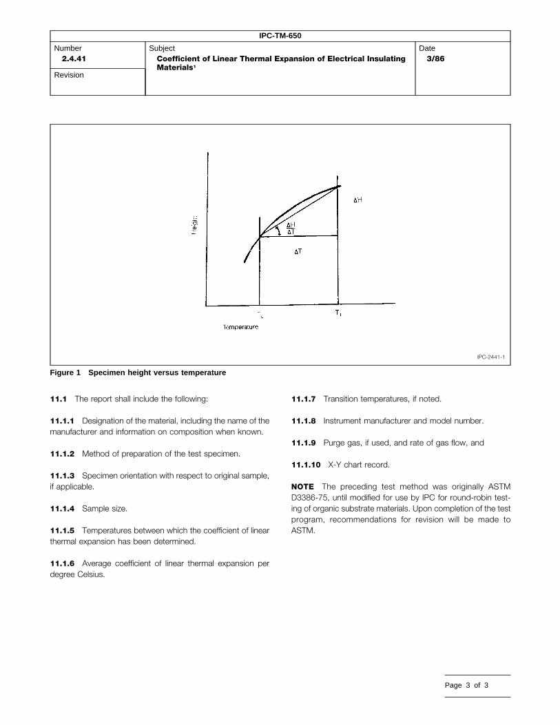
IPC-TM-650
Number2.4.41
SubjectCoefficient of Linear Thermal Expansion of Electrical InsulatingMaterials1
Date3/86
Revision
IPC-2441-1
Figure 1 Specimen height versus temperature
11.1 The report shall include the following:
11.1.1 Designation of the material, including the name of themanufacturer and information on composition when known.
11.1.2 Method of preparation of the test specimen.
11.1.3 Specimen orientation with respect to original sample,if applicable.
11.1.4 Sample size.
11.1.5 Temperatures between which the coefficient of linearthermal expansion has been determined.
11.1.6 Average coefficient of linear thermal expansion perdegree Celsius.
11.1.7 Transition temperatures, if noted.
11.1.8 Instrument manufacturer and model number.
11.1.9 Purge gas, if used, and rate of gas flow, and
11.1.10 X-Y chart record.
NOTE The preceding test method was originally ASTMD3386-75, until modified for use by IPC for round-robin test-ing of organic substrate materials. Upon completion of the testprogram, recommendations for revision will be made toASTM.
Page 3 of 3

1.0 Scope
1.1 To describe the vitreous silica dilatometer method fordetermining the linear thermal expansion of laminated materi-als within the temperature range of –55°C to 100°C. Inorganicsubstrates (non-laminated) shall be tested within a range of–55° to 150°C.
2.0 Applicable Documents
ASTM-E-228 Standard Test Method for Linear ThermalExpansion of Solid Materials with a Vitreous Silica Dilatometer
ASTM-D-696 Test for Coefficient of Linear Thermal Expan-sion of Plastics
ASTM-E-831 Test for Linear Thermal Expansion of SolidMaterials by Thermodilatometry
ASTM-E-77 Verification and Calibration of Liquid-in-GlassThermometers
ASTM-E-220 Calibration of Thermocouples by ComparisonTechniques
ASTM-E-644 Testing Industrial Resistance Thermometers
3.0 Test Specimen
3.1 Laminated materials which may or may not containmetal layers.
3.2 Nominal test specimen dimensions shall be 1/4 inchwide x 2 inch –4 inch long x 1/8 inch minimum thickness. Endsurfaces shall be ground parallel. Any deviation from nominalshould recognize thermal gradients of the temperature cham-ber, thermal lag of specimen and any bending of specimen.Thicknesses under 1/8 inch shall be supported by adequateclamping devices unless it is certain that the specimen willremain straight during testing.
4.0 Apparatus
4.1 Vitreous silica dilatometer of either the tube or push rodtype to determine the change in length of a solid material as afunction of temperature. The temperature is controlled at aconstant heating or cooling rate. The linear thermal expansion
The Institute for Interconnecting and Packaging Electronic Circuits2215 Sanders Road • Northbrook, IL 60062-6135
IPC-TM-650TEST METHODS MANUAL
Material in this Test Methods Manual was voluntarily established by Technical Committees of thand its use or adaptation is entirely voluntary. IPC disclaims all liability of any kind as to the usematerial. Users are also wholly responsible for protecting themselves against all claims or liabiliEquipment referenced is for the convenience of the user and does not imply endorsement by th
and the coefficients of linear thermal expansion (CTE) are cal-culated from the recorded data.
This device measures the difference in thermal expansionbetween a test specimen and the vitreous silica parts of thedilatometer (Figure 1).
4.2 Specimen holder (tube) and probe shall be made of vit-reous silica. The probe contact shall be flat or be rounded toapproximately a 10 mm radius.
4.3 Chamber for uniformly heating and cooling the speci-men. The specimen temperature change rate shall be con-trolled. The temperature gradient in the specimen shall notexceed 0.5°C/cm.
4.4 Transducer, for measuring the difference in lengthbetween the specimen and the specimen holder with anaccuracy of at least ± 0.5µm. The transducer shall be pro-tected or mounted so that temperature changes will not affectthe readings by more than 1.0µm.
4.5 Micrometer, for measuring the reference length, Lo, ofthe specimen with an accuracy of at least ± 25µm.
4.6 Thermocouple, types E, K, or T, for measurement of thespecimen temperature. (Type E is NiCr versus constantan,type K is NiCr versus NiAl and Type T is Cu versus constan-tan.)
4.7 Recorder or data logger for collecting temperatures andlengths.
5.0 Procedure
5.1 Sample Preparation Rough cut with a band saw ormetallurgical cut-off wheel and finish machining by grinding.Care must be exercised to remove roughness from specimenends. The ends shall be parallel to ± .001 inch/inch.
5.2 Sample condition (only for laminated, organic speci-mens).
5.2.1 The specimen shall be immersed in isopropyl alcoholand agitated for twenty seconds.
Number2.4.41.1
SubjectCoefficient of Thermal Expansion by the VitreousSilica (Quartz) Dilatometer Method
Date8/97
RevisionA
Originating Task GroupN/A
e IPC. This material is advisory only, application, or adaptation of thisties for patent infringement.e IPC.
Page 1 of 3

IPC-TM-650
Number2.4.41.1
SubjectCoefficient of Thermal Expansion by the Vitreous Silica (Quartz)Dilatometer Method
Date8/97
RevisionA
IPC-24411-1
Figure 1 Cutaway view of vitreous silica tube dilatometer
5.2.2 Condition E-1/110.
5.2.3 Condition C1-40/23/50.
5.3 Calibration
5.3.1 The transducer shall be calibrated by imposing aseries of known displacements with a precision screwmicrometer or set of end gage blocks.
5.3.2 The temperature sensor shall be calibrated accordingto an appropriate ASTM method (E-220) or procedure recom-mended by the National Bureau of Standards.
5.3.3 The dilatometer, as a total system, shall be calibratedby measuring two reference materials of known thermalexpansion. One of the materials should have an expansionclose to the sample specimen, and the other close to that ofthe dilatometer.
Page 2 of 3
5.3.4 Recommended standard reference materials:
• NBS Fused Silica – SRM 739; CTE ∼ .55 PPM/°C (for cali-bration of dilatometer)
• NBS Single Crystal Sapphire - SRM 732; CTE ∼ 5.5 PPM/°C(for use with ‘‘low expansion’’ materials)
• OFHC Copper; CTE ∼ 17.3 PPM/°C (for use with ‘‘highexpansion’’ materials)
5.3.5 The expansion of the dilatometer system, (∆L/Lo)s,and the calibration constant, for corrections of lead lag, tem-peratures, etc., are determined at 20°C intervals using the fol-lowing equations:
(∆L/Lo)s = (∆L/Lo)t – (∆L/Lo)m
A =(∆LLo ) t – (∆LLo ) s
(∆LLo ) m
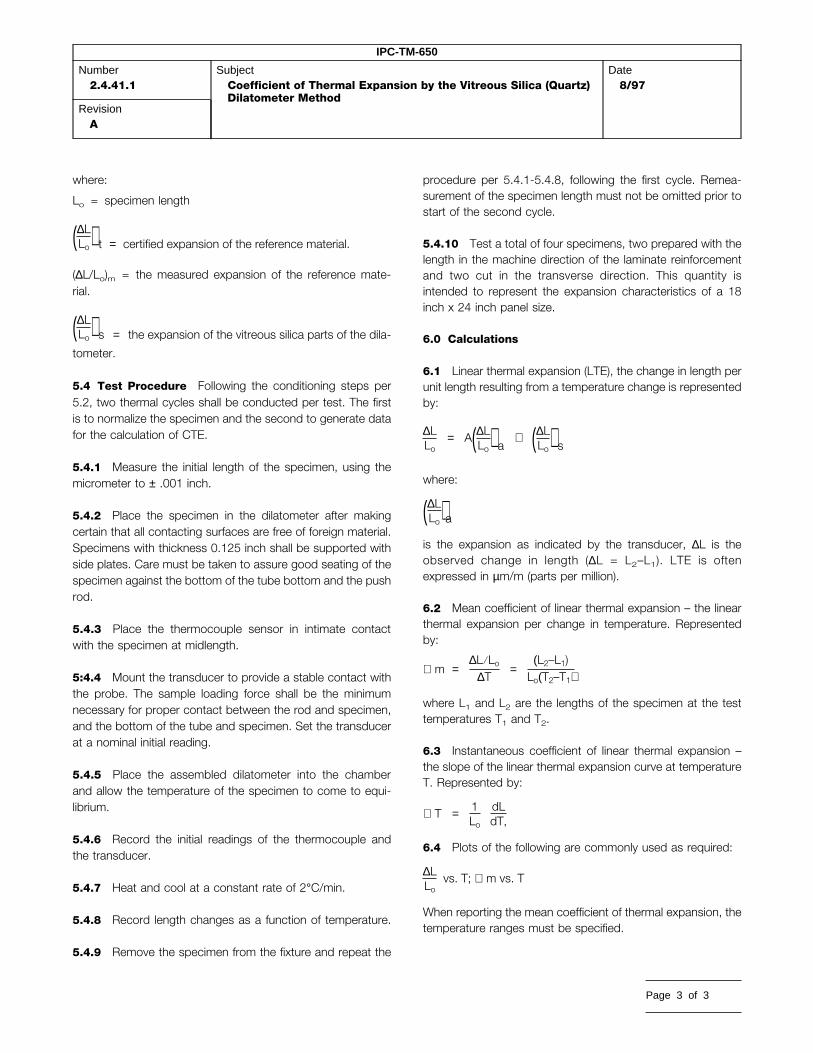
IPC-TM-650
Number2.4.41.1
SubjectCoefficient of Thermal Expansion by the Vitreous Silica (Quartz)Dilatometer Method
Date8/97
RevisionA
where:
Lo = specimen length
(∆LLo ) t = certified expansion of the reference material.
(∆L/Lo)m = the measured expansion of the reference mate-rial.
(∆LLo ) s = the expansion of the vitreous silica parts of the dila-
tometer.
5.4 Test Procedure Following the conditioning steps per5.2, two thermal cycles shall be conducted per test. The firstis to normalize the specimen and the second to generate datafor the calculation of CTE.
5.4.1 Measure the initial length of the specimen, using themicrometer to ± .001 inch.
5.4.2 Place the specimen in the dilatometer after makingcertain that all contacting surfaces are free of foreign material.Specimens with thickness 0.125 inch shall be supported withside plates. Care must be taken to assure good seating of thespecimen against the bottom of the tube bottom and the pushrod.
5.4.3 Place the thermocouple sensor in intimate contactwith the specimen at midlength.
5:4.4 Mount the transducer to provide a stable contact withthe probe. The sample loading force shall be the minimumnecessary for proper contact between the rod and specimen,and the bottom of the tube and specimen. Set the transducerat a nominal initial reading.
5.4.5 Place the assembled dilatometer into the chamberand allow the temperature of the specimen to come to equi-librium.
5.4.6 Record the initial readings of the thermocouple andthe transducer.
5.4.7 Heat and cool at a constant rate of 2°C/min.
5.4.8 Record length changes as a function of temperature.
5.4.9 Remove the specimen from the fixture and repeat the
procedure per 5.4.1-5.4.8, following the first cycle. Remea-surement of the specimen length must not be omitted prior tostart of the second cycle.
5.4.10 Test a total of four specimens, two prepared with thelength in the machine direction of the laminate reinforcementand two cut in the transverse direction. This quantity isintended to represent the expansion characteristics of a 18inch x 24 inch panel size.
6.0 Calculations
6.1 Linear thermal expansion (LTE), the change in length perunit length resulting from a temperature change is representedby:
∆LLo
= A(∆LLo ) a + (∆LLo ) swhere:
(∆LLo )ais the expansion as indicated by the transducer, ∆L is theobserved change in length (∆L = L2–L1). LTE is oftenexpressed in µm/m (parts per million).
6.2 Mean coefficient of linear thermal expansion – the linearthermal expansion per change in temperature. Representedby:
∝ m =∆L/Lo
∆T =(L2–L1)Lo(T2–T1)
where L1 and L2 are the lengths of the specimen at the testtemperatures T1 and T2.
6.3 Instantaneous coefficient of linear thermal expansion –the slope of the linear thermal expansion curve at temperatureT. Represented by:
∝ T = 1Lo
dLdT,
6.4 Plots of the following are commonly used as required:
∆LLo
vs. T; ∝ m vs. T
When reporting the mean coefficient of thermal expansion, thetemperature ranges must be specified.
Page 3 of 3

1.0 Scope This method describes a technique for evaluat-ing a material to resist tracking when subjected to a low cur-rent arc just above the surface of the material. It can be usedon materials of various thickness by stacking materials. Thisprocedure is based on techniques described in ASTM D495.
2.0 Applicable Documents
ASTM D495 Standard Test Method for High Voltage, Low-Current, Dry Arc Resistance of Solid ElectricalInsulation
Manufacturer’s Instruction Manual
3.0 Test Specimens
3.1 Number Three specimens shall be used unless other-wise specified.
3.2 Form Each specimen shall be 3.0 in. x 2.0 in. Materialunder 0.06 in. in thickness shall be built up to provide a speci-men at least 0.06 in. but not exceeding 0.125 in. For very thinlaminates a 1/16 in. laminate of the same type may be usedunder the actual specimen subjected to the arc, permitting areduction of the material required without significantly affectingthe results.
3.3 Location Specimens may be cut from any location in asheet (except from the outer 1 in. of full size sheets).
3.4 Foil Clad Materials All foil clad materials shall have thefoil removed by etching and shall be thoroughly cleaned priorto conditioning or testing.
4.0 Apparatus/Materials
4.1 Arc tester (Beckman ART-11 or equivalent, see ASTMD495).
4.2 Tungsten electrodes (Beckman2 or equivalent, seeASTM D495).
The Institute for Interconnecting and Packaging Electronic Circuits2215 Sanders Road • Northbrook, IL 60062
IPC-TM-650TEST METHODS MANUAL
Material in this Test Methods Manual was voluntarily established by Technical Committees of thand its use or adaptation is entirely voluntary. IPC disclaims all liability of any kind as to the usmaterial. Users are also wholly responsible for protecting themselves against all claims or liabilEquipment referenced is for the convenience of the user and does not imply endorsement by t
4.3 Constant temperature water bath capable of 50°C ±2°C, filled with distilled water.
4.4 Beaker or pan filled with ambient temperature distilledwater.
4.5 Racks for supporting specimens in the water bath withall surfaces exposed.
4.6 Shear, saw or paper cutter for cutting specimen.
4.7 Alcohol or other solvent for cleaning electrode.
4.8 Crocus cloth.
4.9 Gage blocks for checking electrode spacing 0.248 in.and 0.252 in.
4.10 Lint free paper towels.
4.11 Variac3 autotransformer type W1OMT or equivalent.
5.0 Procedure
5.1 Preconditioning Unless otherwise specified the speci-mens shall be conditioned for 48 hours (± 2 hours -0 hours) indistilled water maintained at 50°C ± 2°C. Following this stepthe specimens shall be immersed in ambient temperature dis-tilled water for 30 minutes minimum, 4 hours maximum, toallow them to reach temperature equilibrium without loss ofmoisture.
5.2 Test Conditions The test shall be run at ambient tem-perature 23°C ± 5°C and ambient humidity.
5.3 Equipment set up
5.3.1 The electrode assembly shall be cleaned thoroughlyusing alcohol or other suitable solvent and, if required, withcrocus cloth. The electrode gap shall be adjusted if necessaryto provide a gap of 0.250 in. ± 0.002 in. when the electrodes
Number2.5.1
SubjectArc Resistance of Printed Wiring Material
Date5/86
RevisionB
Originating Task GroupN/A
1. ART-1 or ART-2 manufactured by Beckman Instruments Cedar Grove Essex County New Jersey, U.S.A.2. Electrodes manufactured by Beckman Instruments3. Variac available from General Radio
e IPC. This material is advisory onlye, application, or adaptation of thisities for patent infringement.he IPC.
Page 1 of 2

IPC-TM-650
Number2.5.1
SubjectArc Resistance of Printed Wiring Material
Date5/86
RevisionB
rest on the test specimen.
5.3.2 The arc tester should be set up for operation in theautomatic mode.
5.3.3 Set the Variac to the voltage which produces 12,500volts based on the last calibration of the Instrument (generally105V to 115V).
5.3.4 Reset the timer on the tester to ‘‘0’’ seconds ifrequired.
5.4 Test Procedure
5.4.1 Remove a preconditioned specimen from the ambienttemperature distilled water and wipe dry with a lint free papertowel.
5,4.2 Place a specimen (individual or built up) in the elec-trode fixture.
5.4.3 Operate the tester in accordance with the manufactur-er’s instructions such that an arc is generated and automati-cally switched as indicated below.
Time (sec) On/Off Time Amperage
0-60 0.25 sec/1.75 sec 10 milliamps
60-120 0.25 sec/0.75 sec 10 milliamps
120-180 0.25 sec/0.25 sec 10 milliamps
180 continuous 10 milliamps
5.4.4 Observe the arc carefully and, at the point which thearc disappears and tracking occurs, stop the timer and recordthe time for the specimen to the nearest second.
5.4.5 Remove the specimen, remove and clean the elec-trodes thoroughly using a solvent and if necessary the crocuscloth.
5.4.6 Replace the electrode and check the electrode gap.
Page 2 of 2
5.4.7 Reset the timer and proceed as in 5.4.1 through 5.4.6.
5.5 Calculation
5.5.1 Average the values of the specimens tested from thesame sample and round to the nearest second.
5.6 Report
5.6.1 Report the average value of the arc resistance in sec-onds.
5.6.2 Report the ambient temperature and relative humidityat the time of the test.
5.6.3 Report how the specimen was prepared, e.g. indi-vidual, # of plies built up, or with a spacer.
5.6.4 Report the preconditioning procedure.
5.6.5 Report any anomalies in the test or variations fromprocedures or tolerances specified.
6.0 Note
6.1 The results of arc tests may be significantly affected bycontamination of the electrodes. Any irregularity of the arc inthe early portion of the test may be an indication of contami-nation. If this occurs, the test should be stopped, the elec-trodes cleaned and a fresh specimen should be tested (or thetest may be run in a different area of the same specimen).
6.2 While values for reinforced material may vary with thegrain direction of reinforcement, the effect is generally insignifi-cant with glass reinforced product. At least one specimen inboth machine and transverse direction is recommended toverify this.
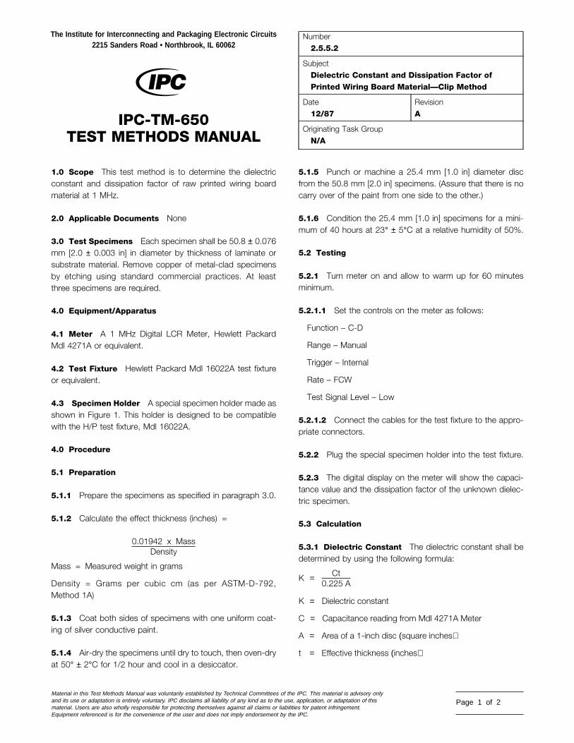
1.0 Scope This test method is to determine the dielectricconstant and dissipation factor of raw printed wiring boardmaterial at 1 MHz.
2.0 Applicable Documents None
3.0 Test Specimens Each specimen shall be 50.8 ± 0.076mm [2.0 ± 0.003 in] in diameter by thickness of laminate orsubstrate material. Remove copper of metal-clad specimensby etching using standard commercial practices. At leastthree specimens are required.
4.0 Equipment/Apparatus
4.1 Meter A 1 MHz Digital LCR Meter, Hewlett PackardMdl 4271A or equivalent.
4.2 Test Fixture Hewlett Packard Mdl 16022A test fixtureor equivalent.
4.3 Specimen Holder A special specimen holder made asshown in Figure 1. This holder is designed to be compatiblewith the H/P test fixture, Mdl 16022A.
4.0 Procedure
5.1 Preparation
5.1.1 Prepare the specimens as specified in paragraph 3.0.
5.1.2 Calculate the effect thickness (inches) =
0.01942 x MassDensity
Mass = Measured weight in grams
Density = Grams per cubic cm (as per ASTM-D-792,Method 1A)
5.1.3 Coat both sides of specimens with one uniform coat-ing of silver conductive paint.
5.1.4 Air-dry the specimens until dry to touch, then oven-dryat 50° ± 2°C for 1/2 hour and cool in a desiccator.
The Institute for Interconnecting and Packaging Electronic Circuits2215 Sanders Road • Northbrook, IL 60062
IPC-TM-650TEST METHODS MANUAL
Material in this Test Methods Manual was voluntarily established by Technical Committees of thand its use or adaptation is entirely voluntary. IPC disclaims all liability of any kind as to the usematerial. Users are also wholly responsible for protecting themselves against all claims or liabiliEquipment referenced is for the convenience of the user and does not imply endorsement by th
5.1.5 Punch or machine a 25.4 mm [1.0 in] diameter discfrom the 50.8 mm [2.0 in] specimens. (Assure that there is nocarry over of the paint from one side to the other.)
5.1.6 Condition the 25.4 mm [1.0 in] specimens for a mini-mum of 40 hours at 23° ± 5°C at a relative humidity of 50%.
5.2 Testing
5.2.1 Turn meter on and allow to warm up for 60 minutesminimum.
5.2.1.1 Set the controls on the meter as follows:
Function – C-D
Range – Manual
Trigger – Internal
Rate – FCW
Test Signal Level – Low
5.2.1.2 Connect the cables for the test fixture to the appro-priate connectors.
5.2.2 Plug the special specimen holder into the test fixture.
5.2.3 The digital display on the meter will show the capaci-tance value and the dissipation factor of the unknown dielec-tric specimen.
5.3 Calculation
5.3.1 Dielectric Constant The dielectric constant shall bedetermined by using the following formula:
K = Ct0.225 A
K = Dielectric constant
C = Capacitance reading from Mdl 4271A Meter
A = Area of a 1-inch disc (square inches)
t = Effective thickness (inches)
Number2.5.5.2
SubjectDielectric Constant and Dissipation Factor ofPrinted Wiring Board Material—Clip Method
Date12/87
RevisionA
Originating Task GroupN/A
e IPC. This material is advisory only, application, or adaptation of thisties for patent infringement.e IPC.
Page 1 of 2

IPC-TM-650
Number2.5.5.2
SubjectDielectric Constant and Dissipation Factor of Printed WiringBoard Material—Clip Method
Date12/87
RevisionA
IPC-2552-1
Figure 1 Special Test Fixture for Dielectric Constant and Dissipation Factor Measurements
5.3.2 Dissipation Factor The dissipation factor value isread directly from the digital display.
5.4 Report The report shall contain the following:
1. Measurement of effective thickness of specimens tested.
2. Capacitance values of the specimens tested.
3. Calculated dielectric constants and averaged measure-ment.
4. Dissipation factor values and averaged measurement.
Page 2 of 2
6.0 Notes
6.1 The dielectric constant is defined as the ratio of thecapacitance with the test material between the two plates tothe capacitance of air between two plates.
6.2 The dissipation factor of a dielectric material is the rela-tionship between the permittivity (capacitance of material) andconductivity (ability to conduct or the reciprocal of the electri-cal resistivity) measured at a given frequency.

1.0 Scope
1.1 Purpose This method is suitable for determining thevolume permittivity, (dielectric constant) and loss tangent (dis-sipation factor) of insulating materials at 1 MHz. It is notdependent on either direct or indirect measurement of speci-men thickness and therefore is very useful for thin films andlaminates but may also be used on specimens up to approxi-mately 6.35 mm [0.25 in] thick.
It is useful for all ranges of permittivity and for loss tangent aslow as 0.0005 providing the range and accuracy of the bridgeused are adequate.
1.2 Description of Method The two fluid method utilizesair as one fluid and a suitable liquid, normally Dow 200 1.0CSsilicone fluid, as the second. Using an established value forthe permittivity of air, the values for the permittivity of the fluidand the sample may easily be calculated. The cell spacing isfixed during all readings but does not need to be known accu-rately for the series of readings required. Since specimens donot require any electrodes to be applied and since manyspecimens can be measured at one time without changingany spacings or machine settings, the method is not only veryaccurate but very rapid.
The method has been used for measurement of PTFE andepoxy glass laminates and flexible films, e.g., polyimide.
Reproducibility lab to lab is excellent for permittivity providedminimal precautions are observed and bridge accuracy isappropriate. On most materials, the effects of small changesin moisture or temperature are larger than any error due to themethod. Lab to lab correlation on stable material such asPTFE have shown results to be consistently within 0.005 or(0.20%).
2.0 Applicable Document
3.0 Test Specimens
The Institute for Interconnecting and Packaging Electronic Circuits2215 Sanders Road • Northbrook, IL 60062
IPC-TM-650TEST METHODS MANUAL
Material in this Test Methods Manual was voluntarily established by Technical Committees of thand its use or adaptation is entirely voluntary. IPC disclaims all liability of any kind as to the usematerial. Users are also wholly responsible for protecting themselves against all claims or liabiliEquipment referenced is for the convenience of the user and does not imply endorsement by th
3.1 Number Unless otherwise specified in the materialspecification, one specimen is adequate for materials whichare uniform, e.g., unreinforced plastics. For woven reinforcedmaterials where resin content may vary, at least 2 specimens,representing the thinnest and thickest part of the sample,should be tested. For material with random reinforcement, aminimum of three specimens from the edge and center of thesheet are recommended to characterize variation within thesheet.
3.2 Form Individual specimens shall be 81.3 mm ± 1.3 mmx 81.3 to 101.6 mm [3.2 in ± 0.05 in x 3.2 in to 4.0 in] x thick-ness.
For materials under 0.254 mm [0.010 in], individual specimensshould be stacked to a minimum of 0.381 mm [0.015 in] tomaximize accuracy. Thinner specimen buildups may be usedif the correlation with the 0.381 mm [0.015 in] specimen iswithin the required accuracy for the particular equipment, cellspacing and material being tested.
3.3 Foil Clad Materials All foil clad materials shall have themetal cladding completely removed by etching and shall berinsed and dried prior to conditioning.
3.4 Marking Mark each specimen in the upper left cornerwith an engraving pencil or an ink which is not soluble in theDow Corning 200 fluid.
4.0 Apparatus/Materials
4.1 1 MHz Capacitance Bridge with 0-200 (or 0-100) pfrange.1
4.2 Cell Balsbaugh LD-32 or equivalent (see Figure 1) threeterminal cell. Note: For accuracy of 1% or better, room tem-perature must not vary more than 1°C during measurements.Temperature control is necessary if laboratory variationexceeds these limits.
Number2.5.5.3
SubjectPermittivity (Dielectric Constant) and Loss Tangent(Dissipation Factor) of Materials (Two Fluid CellMethod)
Date12/87
RevisionC
Originating Task GroupN/A
1. Capacitance Bridge—Suggested is Boonton 76A automatic capacitance bridge. This model has adequate capacitance range and adequate conductance resolu-tion (0.001 microsiemen) to permit measurement of dissipation factors down to approximately 0.0005. Other bridges, e.g., Boonton 75D, are also adequate forlow loss materials and some other bridges may be suitable for higher loss materials, such as epoxy where dissipation factors exceed 0.01 and resolution of 0.01microsiemen or even 0.1 microsiemen may be adequate.
2. Balsbaugh LD-3 Gillian and Co,, Watertown, MA, (617) 624-5688 or Zincast Corporation, 44 Homestead Ave., Stanford, CT 06902, (203) 359-0109
e IPC. This material is advisory only, application, or adaptation of thisties for patent infringement.e IPC.
Page 1 of 4
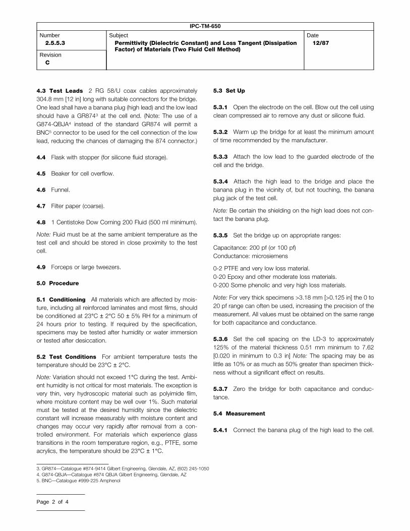
IPC-TM-650
Number2.5.5.3
SubjectPermittivity (Dielectric Constant) and Loss Tangent (DissipationFactor) of Materials (Two Fluid Cell Method)
Date12/87
RevisionC
4.3 Test Leads 2 RG 58/U coax cables approximately304.8 mm [12 in] long with suitable connectors for the bridge.One lead shall have a banana plug (high lead) and the low leadshould have a GR8743 at the cell end. (Note: The use of aG874-QBJA4 instead of the standard GR874 will permit aBNC5 connector to be used for the cell connection of the lowlead, reducing the chances of damaging the 874 connector.)
4.4 Flask with stopper (for silicone fluid storage).
4.5 Beaker for cell overflow.
4.6 Funnel.
4.7 Filter paper (coarse).
4.8 1 Centistoke Dow Corning 200 Fluid (500 ml minimum).
Note: Fluid must be at the same ambient temperature as thetest cell and should be stored in close proximity to the testcell.
4.9 Forceps or large tweezers.
5.0 Procedure
5.1 Conditioning All materials which are affected by mois-ture, including all reinforced laminates and most films, shouldbe conditioned at 23°C ± 2°C 50 ± 5% RH for a minimum of24 hours prior to testing. If required by the specification,specimens may be tested after humidity or water immersionor tested after desiccation.
5.2 Test Conditions For ambient temperature tests thetemperature should be 23°C ± 2°C.
Note: Variation should not exceed 1°C during the test. Ambi-ent humidity is not critical for most materials. The exception isvery thin, very hydroscopic material such as polyimide film,where moisture content may be well over 1%. Such materialmust be tested at the desired humidity since the dielectricconstant will increase measurably with moisture content andchanges may occur very rapidly after removal from a con-trolled environment. For materials which experience glasstransitions in the room temperature region, e.g., PTFE, someacrylics, the temperature should be 23°C ± 1°C.
Page 2 of 4
5.3 Set Up
5.3.1 Open the electrode on the cell. Blow out the cell usingclean compressed air to remove any dust or silicone fluid.
5.3.2 Warm up the bridge for at least the minimum amountof time recommended by the manufacturer.
5.3.3 Attach the low lead to the guarded electrode of thecell and the bridge.
5.3.4 Attach the high lead to the bridge and place thebanana plug in the vicinity of, but not touching, the bananaplug jack of the test cell.
Note: Be certain the shielding on the high lead does not con-tact the banana plug.
5.3.5 Set the bridge up on appropriate ranges:
Capacitance: 200 pf (or 100 pf)Conductance: microsiemens
0-2 PTFE and very low loss material.0-20 Epoxy and other moderate loss materials.0-200 Some phenolic and very high loss materials.
Note: For very thick specimens >3.18 mm [>0.125 in] the 0 to20 pf range can often be used, increasing the precision of themeasurement. All values must be obtained on the same rangefor both capacitance and conductance.
5.3.6 Set the cell spacing on the LD-3 to approximately125% of the material thickness 0.51 mm minimum to 7.62[0.020 in minimum to 0.3 in] Note: The spacing may be aslittle as 10% or as much as 50% greater than specimen thick-ness without a significant effect on results.
5.3.7 Zero the bridge for both capacitance and conduc-tance.
5.4 Measurement
5.4.1 Connect the banana plug of the high lead to the cell.
3. GR874—Catalogue #874-9414 Gilbert Engineering, Glendale, AZ, (602) 245-10504. G874-QBJA—Catalogue #874 QBJA Gilbert Engineering, Glendale, AZ5. BNC—Catalogue #999-225 Amphenol

IPC-TM-650
Number2.5.5.3
SubjectPermittivity (Dielectric Constant) and Loss Tangent (DissipationFactor) of Materials (Two Fluid Cell Method)
Date12/87
RevisionC
5.4.2 Record the capacitance of the air filled cell as C1 tothe nearest .01 pf (or nearest .001 pf if the 0-20 pf scale isused).
5.4.3 Remove the specimen from the humidity controlledenvironment.
5.4.4 Insert the first specimen to be tested with the markedcorner remaining in the upper left and the right side of the testspecimen against one side of the test cell. Note: This willensure that subsequent measurements are taken using thesame area of the specimen.
5.4.5 Read and record the value of capacitance with thespecimen in the cell as C3.
5.4.6 Remove the first specimen and obtain C3 for any otherspecimens to be measured with same cell spacing.
5.4.7 After removing the last specimen from the cell, fill thecell with Dow Corning 200 Fluid using the funnel and a filter toremove any small particles from the fluid and collect anyexcess fluid from the overflow pipe on the cell with the smallbeaker.
5.4.8 Allow a few seconds for the temperature of the celland fluid to equilibrate and record the capacitance of the liq-uid filled cell as C2.
Note: If the capacitance is drifting consistently in one direc-tion, the fluid is not at equilibrium.
5.4.9 Record the conductance of the fluid filled as cell G1.
Note: The value obtained will vary somewhat with cell spacingand humidity but should not exceed 500 microsiemen (200microsiemen if low loss material, with a loss tangent under.001 is being tested). Values beyond this are generally indica-tive of problems with the leads, contamination of the fluid orbridge error and must be corrected if correct dissipation fac-tor is to be determined.
5.4.10 Insert the first specimen in the fluid filled cell exactlyas in the dry reading and record the value of the capacitanceas C4 and the value of the conductance as G2.
Note: Values should stabilize within a few seconds after speci-men insertion. If they do not there is very likely air trapped inthe cell. This is quite common if multiple thin specimens are
used to form one test specimen. If this occurs presoaking thespecimen with fluid before immersion and inserting one ply ata time should eliminate the problem.
5.4.11 Remove the first specimen and insert each subse-quent specimen in the same order as the dry values wereobtained and record the C4 and G2 values for each.
5.4.12 After the last specimen is measured and removedfrom fluid, check and record the values of the capacitanceand conductance.
Note: If the level of the fluid with the specimen removed doesnot cover the electrodes, fill the cell before checking the finalvalues. This check on C2 will be used to verify the amount ofinfluence that changes in ambient temperature have had onthe values obtained.
6.0 Calculation
6.1 Calculate the value of the permittivity (dielectric constant)of each specimen tested using the equation:
DK = 1.00058C1 SC1 +
(C3−C1) (C2−C1) C4(C3−C1) C4 − (C4−C2) C3 D
Round the value obtained to the nearest .01.
6.2 Calculate the value of the loss tangent (dissipation fac-tor) of each specimen tested using the equation:
DF = G26.2832 C4
+ S DK * .99942 C1−C4C 4−C2 D S G2
6.2832 C4− G16.2832 C2D
Round the value to the nearest .0001.
Note: Values should be calculated using a computer and mustnot be rounded prematurely.
6.3 If the value of C2 changed during the course of the mea-surements, use the final values of C2 and G2, the value of C1,and the values on the last specimen for C3 and C4 to recalcu-late the DK and Df of the final specimen. If the difference in DKvalues is significant, the temperature of the cell must be con-trolled more precisely during the measurement period.
6.4 Calculate the average permittivity (dielectric constant) (ifmore than one specimen was tested).
6.5 Calculate the average loss tangent (dissipation factor) (ifmore than one specimen was tested).
7.0 Report
Page 3 of 4

IPC-TM-650
Number2.5.5.3
SubjectPermittivity (Dielectric Constant) and Loss Tangent (DissipationFactor) of Materials (Two Fluid Cell Method)
Date12/87
RevisionC
7.1 Report the minimum, maximum and average values ofthe permittivity (dielectric constant).
7.2 Report the average value of the loss tangent (dissipationfactor).
7.3 Report the specimen preconditioning, e.g., C-24/23/50.
7.4 Report the actual test conditions for temperature andhumidity.
7.5 Report if the specimen was built up.
7.6 Report the approximate cell spacing.
7.7 Report any anomalies in the test or variations from theprescribed procedures or tolerances.
IPC-2553-1
Figure 1
Page 4 of 4

1.0 Scope This method describes a procedure for deter-mining the ability of rigid insulating materials to resist break-down parallel to laminations (or in the plane of the material)when subjected to extremely high voltages at standard ACpower frequencies of 50-60Hz.
As for most electrical properties, values obtained on mostmaterials are highly dependent on the moisture content andtests using different conditioning cannot be compared. Testsin other mediums, e.g., air are generally impractical due to itsrelatively low breakdown.
This method is based on the test technique described asASTM D229.
2.0 Applicable documents
ASTM D229 Standard Method of Testing Rigid Sheet andPlate Materials Used for Electrical Insulation
ASTM D149 Standard Test Method for Dielectric BreakdownVoltage and Dielectric Strength of Solid Electrical InsulatingMaterials at Commercial Power Frequencies
3.0 Test Specimens
3.1 Number Four specimens shall be tested. When speci-fied, two shall be in the machine direction and two in thetransverse direction for reinforced materials.
3.2 Form Specimens shall be approximately 3.0 inch X 2.0inch X thickness and shall be prepared by shearing or sawingthe specimen from the test sample. Two holes 0.188 inch indiameter are to be drilled along the center line of the 3.0 inchdimension and midway between the edges in the 2.0 inchdimension, with a spacing of 1.0 inch ± .01 inch center tocenter.
3.3 Location The specimens may be cut from any locationin the sheet (except from the outer 1.0 inch of full size sheets).
3.4 Foil Clad Material Foil clad material shall have allmetal cladding removed by etching and shall be thoroughlycleaned prior to conditioning or testing.
The Institute for Interconnecting and Packaging Electronic Circuits2215 Sanders Road • Northbrook, IL 60062
IPC-TM-650TEST METHODS MANUAL
Material in this Test Methods Manual was voluntarily established by Technical Committees of theand its use or adaptation is entirely voluntary. IPC disclaims all liability of any kind as to the use,material. Users are also wholly responsible for protecting themselves against all claims or liabilitEquipment referenced is for the convenience of the user and does not imply endorsement by the
4.0 Apparatus/Materials
4.1 High voltage breakdown tester (generally 50KV mini-mum) with current rating of .5KVA up to 10KV and 5KVAabove 10KV and a motorized control capable of a 500 volts/second rate of rise.
4.2 Oil tank filled with insulating oil1 capable of exceedingthe requirements of the specification.
4.3 Tapered pin electrode fixture utilizing two AmericanStandard #3 pins. (Note spherical ends on the pins are per-mitted and recommended to reduce likelihood of breakdownin the oil.)
4.4 High voltage test leads (leads rated in excess of machinecapacity are recommended).
4.5 Constant temperature water bath, capable of 50°C ±2°C, filled with distilled water.
4.6 Beaker or pan filled with ambient temperature distilledwater.
4.7 Racks for supporting specimens in the 50°C water bath(with all specimen surfaces exposed).
4.8 Timer 0-60 seconds.
4.9 Lint free paper towels.
5.0 Procedure
5.1 Preconditioning Unless otherwise specified the speci-men shall be conditioned for 48 hours (+2 hours –0 hours) indistilled water maintained at 50°C ± 2°C.
Following this step the specimen shall be immersed in ambi-ent temperature distilled water for 30 minutes minimum, 4hours maximum, to allow the specimens to achieve tempera-ture equilibrium without a substantial change in moisture con-tent.
Number2.5.6
SubjectDielectric Breakdown of Rigid Printed WiringMaterial
Date5/86
RevisionB
Originating Task GroupN/A
1. Insulating Oil: Transfer oil such as Shell Dial Ax may be used. Use of dibutyl phthalate is acceptable but it may cause failure of the adhesives used for plastictanks.
IPC. This material is advisory onlyapplication, or adaptation of this
ies for patent infringement.IPC.
Page 1 of 3

IPC-TM-650
Number2.5.6
SubjectDielectric Breakdown of Rigid Printed Wiring Material
Date5/86
RevisionB
5.2 Test Condition The test shall be performed at ambienttemperature (23°C ± 5°C). Relative humidity is not significantas the tests are performed under oil.
5.3 Equipment Set Up
5.3.1 Adjust the transformer on the high voltage tester(manually for most models) to the position which will allow forthe necessary voltage to be achieved with adequate currentcapacity for breakdown.
5.3.2 Set the machine for testing using a 500 volt per sec-ond rate of rise.
5.4 Test
5.4.1 Remove a preconditioned specimen from the ambienttemperature water and wipe dry with a lint free paper towel.
5.4.2 Insert the first specimen into the fixture (inserting thetapered pins from opposite sides) and immerse in the oil bath.
5.4.3 Attach leads (if not permanently wired) so that onehigh voltage lead is connected to one tapered pin electrodeand the ground lead is connected to the other tapered pinelectrode.
5.4.4 Operate the tester such that the voltage is applied witha 500 volts per second rate of rise and observe the specimenuntil an electrical breakdown occurs.
5.4.5 Record the voltage at which breakdown occurs, usingthe meter memory device if available. Note: If the breakdownappears to be in the oil and no specimen damage is obviousit is recommended that the same sample be retested. If thespecimen still will not breakdown due to breakdown of the oil,the oil should be filtered or replaced.
5.4.6 Determine the starting voltage and steps for theremaining specimens from the same sample from Table 1.
5.4.7 Change the high voltage tester to manual (or pro-grammed stepped) operation, remove a specimen from thewater bath, wipe dry, and insert the second specimen.
5.4.8 Set the voltage to the 50% value (plus or minus thevalue of one step) and apply the voltage for 60 seconds.
5.4.9 If no breakdown occurs increase the voltage in steps
Page 2 of 3
per Table 1 until the material breaks down or the breakdowncapacity of the machine or oil is reached. Record the break-down voltage to the nearest kilovolt or record ‘‘N. B.’’ if thereis no breakdown of the material. Note: If the minimum valuerequired by the material specification is not exceeded, butmaterial breakdown does not occur, it is necessary to replaceor filter the oil.
5.4.10 Repeat steps 5.4.7-5.4.9 for the remaining speci-mens from the sample.
5.5 Calculation
5.5.1 Average the values for the three specimens testedusing the stepped technique and round to the nearest kilovolt.Even if some specimens do not break down, the maximumindividual voltages will be used to calculate an average. Note:If the accuracy of the meter on the machine is not within 5%for all values in the range, apply a correction obtained from thelast machine calibration to each reading to determine theactual value for the dielectric breakdown.
5.6 Report
5.6.1 Report the average value of the dielectric breakdown(if all specimens actually breakdown), e.g., 85KV average.
5.6.2 Report the average with a plus after the value if one ortwo specimens do not break down, e.g., 82 + KV average2NB.
5.6.3 Report the minimum value at which the oil brokedown, if no actual specimen breakdowns are obtained, e.g.,75 + KV N.B.
5.6.4 Report any anomalies in the test or any variations fromprescribed procedures or tolerances.
6.0 Notes
Table 1 Voltage increments for Step by Step Test
Breakdown Voltage (KV) Increment KV
less than 12.5 0.5
over 12.5 to 25 1.0
over 25 to 50 2.5
over 50 to 100 5
over 100 10

IPC-TM-650
Number2.5.6
SubjectDielectric Breakdown of Rigid Printed Wiring Material
Date5/86
RevisionB
6.1 The dielectric breakdown of the material may beadversely affected if the drilling process used to produce theholes is inadequate. Use of a sharp high speed drill is recom-mended to prevent burning the material or producing roughholes.
6.2 This test requires voltages which are life threatening. TheHigh Voltage Tester must be installed and operated in accor-dance with the manufacturer’s instructions. If the test cham-ber is not totally enclosed, with a safety interlock, extremecare must be exercised in performance of the test.
Page 3 of 3

1.0 Scope This method describes a technique for evaluat-ing the ability of an insulating material to resist electrical break-down perpendicular to the plane of the material when sub-jected to short term, high voltages at standard AC powerfrequencies of 50-60 Hz.
1.1 Applicability and Use of Data This method may beused on material of any thickness up to approximately 0.125inch, however, for material over 0.020 inch, other methodssuch as dielectric breakdown are normally used to character-ize a material’s electrical integrity. Results of this test may bedrastically affected by moisture content, and results obtainedusing different preconditioning may not be comparable.
This method uses an oil medium to prevent flashover on asmall specimen and results may not be comparable to testsrun in air. Values obtained using this method should not beused for predicting the insulating ability of ultra thin metal cladlaminates.
The values determined by this method generally decrease withincreasing specimen thickness for otherwise identical material.This method is based on the techniques described in ASTMD149.
2.0 Applicable Document
ASTM D149 Standard Test Method for Dielectric BreakdownVoltage and Dielectric Strength of Solid Electrical InsulatingMaterials at Commercial Power Frequencies
3.0 Test Specimens
3.1 Number Three specimens shall be prepared unlessotherwise specified.
3.2 Form Specimens should be 4.0 inch ± 1.0 inch X 4.0 ±1.0 inch; however, size is not critical as long as no flashoveroccurs around the edges.
The Institute for Interconnecting and Packaging Electronic Circuits2215 Sanders Road • Northbrook, IL 60062
IPC-TM-650TEST METHODS MANUAL
1. Edges: For a reinforced laminate the specimens shall be from opposite edges of2. Current capacity: 40 milliamps is normally satisfactory.3. Insulating oil: Shell Dial AX Insulating Oil has been found suitable for breakdowns
Material in this Test Methods Manual was voluntarily established by Technical Committees of tand its use or adaptation is entirely voluntary. IPC disclaims all liability of any kind as to the usmaterial. Users are also wholly responsible for protecting themselves against all claims or liabEquipment referenced is for the convenience of the user and does not imply endorsement by
3.3 Location Specimens shall be cut by any convenientmeans from both edges1 and the center of the laminate(except no specimen shall be taken closer than 1 inch fromthe edge of full size sheets).
3.4 Foil Clad Material Foil clad materials shall have allmetal cladding removed by etching and should be thoroughlycleaned prior to conditioning or testing.
3.5 Uncured Material Uncured material must be fullycured. Under normal conditions, two ply lamination is recom-rnended for comparison of prepreg material. Single ply lami-nates are recommended for cover lays and similar productsdesigned for single ply usage.
4.0 Apparatus/Materials
4.1 High voltage breakdown tester, 25 KV, minimum with anadequate current rating2, a motorized control capable of 500volts per second rate of rise and a meter capable of indicatingbreakdown voltage within 5% over the entire range of actualbreakdown voltages (generally 1 KV to 20 KV).
4.2 Oil tank filled with insulating oil3.
4.3 Electrode test set 2 inch diameter electrodes with 1/4inch radius on the edge of the electrodes and 50 g. ± 2 g.load applied by the weight of upper electrode (in air).
4.4 Two high voltage test leads (leads rated in excess of thetester voltage capability are recommended).
4.5 Micrometer capable of resolving at least 0.0001 inch.Note: For accurate measurement of material under 0.005 inchtest accuracy may be severely limited by the ability to measurethe specimen accurately.
4.6 Constant temperature water bath, capable of maintain-ing 50°C ± 2°C, filled with distilled water.
Number2.5.6.2
SubjectElectric Strength of Printed Wiring Material
Date8/97
RevisionA
Originating Task GroupN/A
the reinforcement.
up to 100 KV.
he IPC. This material is advisory onlye, application, or adaptation of thisilities for patent infringement.the IPC.
Page 1 of 3
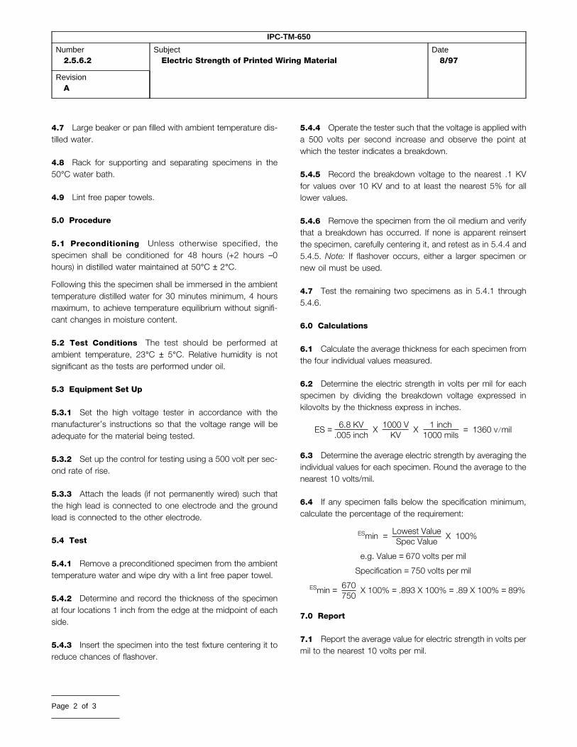
IPC-TM-650
Number2.5.6.2
SubjectElectric Strength of Printed Wiring Material
Date8/97
RevisionA
4.7 Large beaker or pan filled with ambient temperature dis-tilled water.
4.8 Rack for supporting and separating specimens in the50°C water bath.
4.9 Lint free paper towels.
5.0 Procedure
5.1 Preconditioning Unless otherwise specified, thespecimen shall be conditioned for 48 hours (+2 hours –0hours) in distilled water maintained at 50°C ± 2°C.
Following this the specimen shall be immersed in the ambienttemperature distilled water for 30 minutes minimum, 4 hoursmaximum, to achieve temperature equilibrium without signifi-cant changes in moisture content.
5.2 Test Conditions The test should be performed atambient temperature, 23°C ± 5°C. Relative humidity is notsignificant as the tests are performed under oil.
5.3 Equipment Set Up
5.3.1 Set the high voltage tester in accordance with themanufacturer’s instructions so that the voltage range will beadequate for the material being tested.
5.3.2 Set up the control for testing using a 500 volt per sec-ond rate of rise.
5.3.3 Attach the leads (if not permanently wired) such thatthe high lead is connected to one electrode and the groundlead is connected to the other electrode.
5.4 Test
5.4.1 Remove a preconditioned specimen from the ambienttemperature water and wipe dry with a lint free paper towel.
5.4.2 Determine and record the thickness of the specimenat four locations 1 inch from the edge at the midpoint of eachside.
5.4.3 Insert the specimen into the test fixture centering it toreduce chances of flashover.
Page 2 of 3
5.4.4 Operate the tester such that the voltage is applied witha 500 volts per second increase and observe the point atwhich the tester indicates a breakdown.
5.4.5 Record the breakdown voltage to the nearest .1 KVfor values over 10 KV and to at least the nearest 5% for alllower values.
5.4.6 Remove the specimen from the oil medium and verifythat a breakdown has occurred. If none is apparent reinsertthe specimen, carefully centering it, and retest as in 5.4.4 and5.4.5. Note: If flashover occurs, either a larger specimen ornew oil must be used.
4.7 Test the remaining two specimens as in 5.4.1 through5.4.6.
6.0 Calculations
6.1 Calculate the average thickness for each specimen fromthe four individual values measured.
6.2 Determine the electric strength in volts per mil for eachspecimen by dividing the breakdown voltage expressed inkilovolts by the thickness express in inches.
ES = 6.8 KV.005 inch
X 1000 VKV
X 1 inch1000 mils
= 1360 v/mil
6.3 Determine the average electric strength by averaging theindividual values for each specimen. Round the average to thenearest 10 volts/mil.
6.4 If any specimen falls below the specification minimum,calculate the percentage of the requirement:
ESmin = Lowest ValueSpec Value
X 100%
e.g. Value = 670 volts per mil
Specification = 750 volts per mil
ESmin = 670750
X 100% = .893 X 100% = .89 X 100% = 89%
7.0 Report
7.1 Report the average value for electric strength in volts permil to the nearest 10 volts per mil.

IPC-TM-650
Number2.5.6.2
SubjectElectric Strength of Printed Wiring Material
Date8/97
RevisionA
7.2 Report the minimum value in percent of requirement if itis below the requirement for average electric strength.
7.3 Report the actual thickness range of the material testedincluding the minimum and maximum individual thicknessmeasurements.
7.4 Report any anomalies in the test or any variations fromthe prescribed procedures or tolerances.
8.0 Notes
8.1 This test method may be modified to an air medium topredict performance in normal environments more accurately,however, unless the electrode is effectively guarded, thebreakdown will generally occur in air.
8.2 For testing the effect of copper foil on clad laminateunder 0.005 inch it is suggested that two inch circular elec-trodes be left on the 4 inch X 4 inch specimen by etching. Theground electrode may be slightly larger to assure registration.
8.3 For materials which are compressible, a standard pres-sure of 25 PSI is to be used for determining specimen thick-ness.
Page 3 of 3

1.0 Scope This test method is designed to determine vol-ume resistivity and surface resistivity of metallic-clad or uncladlaminates under conditions of specified humidity and tempera-ture and at elevated temperatures.
2.0 Applicable Documents
ASTM-D-257 D-C Resistance or Conductance of InsulatingMaterials
IPC-TM-650
Method 2.3.6, Etching, Ammonium PersulfateMethod, 2.3.7 Etching, Ferric ChlorideMethod 2.3.7.1, Cupric Chloride EtchingMethod 2.6.3, Moisture and Insulation Resistance, Rigid,Rigid/Flex and Flex Printed Wiring Boards
3.0 Test Specimens
3.1 Laminate thickness of 0.51 mm [0.020 in] or greater.Three specimens of dimensions 101.6 ± 3.2 mm x 101.6 ±3.2 mm [4.0 ± 0.125 in x 4.0 ± 0.125 in] by thickness shall beprepared for each test condition, unless otherwise specified.
3.2 Laminate thickness of less than 0.51 mm [0.020 in].Three specimens of dimensions 50.8 ± 1.6 mm x 50.8 ± 1.6mm [2.0 ± 0.062 x 2.0 ± 0.062 in] by the thickness shall beprepared for each test condition, unless otherwise specified.
4.0 Equipment Apparatus
4.1 Conditioning chamber capable of maintaining 35 ± 2°C[95 ± 3.6°F] and 90 +5, –0% relative humidity.
4.2 Conditioning chamber capable of attaining the tempera-ture and humidity conditions specified in IPC-TM-650, Method2.6.3.
4.3 Air circulating oven capable of maintaining the specifiedtest temperatures to within ± 2°C [±3.6°F].
4.4 Resistance measuring instrumentation capable of mea-suring to 1012 meg-ohms, minimum, with an accuracy of ± 5percent at its highest scale setting. The equipment shall havethe capability of applying 500 volts dc to the test specimen.
The Institute for Interconnecting and Packaging Electronic Circuits2215 Sanders Road • Northbrook, IL 60062
IPC-TM-650TEST METHODS MANUAL
Material in this Test Methods Manual was voluntarily established by Technical Committees of thand its use or adaptation is entirely voluntary. IPC disclaims all liability of any kind as to the usmaterial. Users are also wholly responsible for protecting themselves against all claims or liabilEquipment referenced is for the convenience of the user and does not imply endorsement by t
4.5 A system/fixture for electrical connections into the tem-perature and humidity chambers (see 4.1, 4.2, 4.3). Threeseparate cables shall be provided to make connections toeach specimen being conditioned/tested. The center conduc-tor of each cable shall be connected to one of the three elec-trodes applied to the test specimen. The opposite ends of thecables shall be brought outside the chamber and terminatedat a convenient location for connection to the measuringinstrument. Shields shall be trimmed back from the ends ofthe center conductor insulation and interconnected to theguard post of the measuring instrument. See 6.2 for additionalinformation.
Support the specimen parallel to the air flow through thechamber during conditioning.
Special care should be taken to ensure that materials used inthe fixture are such that resistance readings are that of thematerial being tested and not the fixture.
4.6 A measurement device capable of measuring laminatethickness to the nearest 0.0025 mm [0.0001 in].
4.7 Material and apparatus for formation of specimen con-ductors.
4.7.1 Conductor silver paint; composition 4817 by DupontCompany, or equivalent.
4.7.2 A system for applying the paint to the specimen, suchas silk screening.
4.7.3 A mask, fixture, photoprinting system, or equivalent,for applying the applicable electrodes/test pattern to thespecimen (See Dimension Table).
4.8 Etching system in accordance with IPC-TM-650,Method 2.3.6, 2.3.7, or 2.3.7.1.
5.0 Procedure
5.1 Specimen Preparation
5.1.1 Test patterns with the applicable dimensions shown inthe Dimension Table, and in accordance with Figures 1, 2,and 3 shall be generated, as follows:
Number2.5.17.1
SubjectVolume and Surface Resistivity of DielectricMaterials
Date12/94
RevisionA
Originating Task GroupMIL-P-13949 Test Methods Task Group (7-11b)
e IPC. This material is advisory onlye, application, or adaptation of thisities for patent infringement.he IPC.
Page 1 of 4

IPC-TM-650
Number2.5.17.1
SubjectVolume and Surface Resistivity of Dielectric Materials
Date12/94
RevisionA
Dimension Table
BaseThickness D 1 Diameter D 2 Diameter D 3 Diameter D 4 D5 A(cm 2) P/D4
Less than0.51 mm
(0.020 inches)
1.000(2.540)
1.020(2.591)
1.375(3.493)
0.010(0.025)
0.177(0.460)
5.169 317.4
±0.005(0.013)
±0.005(0.013)
±0.005(0.013)
±0.001(0.003)
±0.005(0.013)
0.51 mm(0.020 inches)and greater
2.000(5.080)
2.500(6.350)
3.000(7.520)
0.250(0.636)
0.250(0.636)
25.652 28.27
±0.015(0.038)
±0.015(0.038)
±0.015(0.038)
±0.005(0.038)
±0.015(0.038)
For the above: Do = (D1 + D2)/2A = πDo2
4P = πDO
Note: Dimensions are in inches with metric equivalents in parenthesis (1 inch = 2.54 cm).
5.1.1.1 Metallic-clad materials having a thickness of lessthan 0.51 mm [0.020 in] shall be photoprinted with a patternof the outline of the conductors and etched in accordancewith IPC-TM-650, Methods 2.3.6, 2.3.7, or 2.3.7.1. The elec-trodes shall then be completed (filled in) using silver conduc-tive paint.
5.1.1.2 Metallic-clad laminates 0.51 mm [0.020 in] or thickershall be etched in accordance with IPC-TM-650, Method2.3.6, 2.3.7, or 2.3.7.1. A pattern of the outline of the conduc-tors may be photoprinted before etching. Test electrodes shallbe applied using silver conductive paint and an appropriatetest pattern application system.
5.1.1.3 Solid metal foil electrodes shall not be acceptable inany case, except for the outer electrode for laminates lessthan 0.51 mm [0.020 in]. A small pad of retained cladding maybe retained within the electrode borders to facilitate solderingof leads.
5.1.2 If soldering techniques are used to attach leads, suit-able cleaning procedures shall be used to remove flux andother residue.
5.2 Conditioning
5.2.1 Humidity Conditioning
5.2.1.1 Specimens of a thickness less than 0.51 mm [0.020in] shall be subjected to 90 + 5-0% relative humidity and 35 ±2°C [95 ± 3.6°F] for a period of 96 +2, -0 hours prior to elec-trical measurement.
Page 2 of 4
5.2.1.2 Specimens of a thickness greater than, or equal to,0.51 mm [0.020 in] shall be subjected to the conditioningspecified in IPC-TM-650, Method 2.6.3, paragraph 5.1.3. Fol-lowing the tenth cycle, the conditioning chamber shall main-tain a temperature of 25 ± 2°C [77 ± 3.6°F] and 90 +5, 0%relative humidity during the interval that electrical measure-ments are being made.
5.2.2 At Elevated Temperature Conditioning Speci-mens shall be subjected to the specified temperature (basedon material type and specification requirements) for a periodof 24 hours -0, +2 hours. Unless otherwise specified, the tem-perature shall be 125 ± 2°C [257 ± 3.6°F].
5.3 Electrical Measurements All electrical measurementsshall be made inside the applicable conditioning chamber andat the conditions specified in 5.2.
5.3.1 Electrical measurements taken on specimens condi-tioned in accordance with paragraph 5.2.1 shall be completedwithin the 2 hour tolerance of the conditioning.
5.3.2 Electrical measurements taken on specimens condi-tioned in accordance with paragraph 5.2.2 shall be made afterachieving 1.5 hours steady state of 25 ± 2°C [77 ± 3.6°F] and90 +5, -0% relative humidity. All measurements shall be com-pleted within 2 hours.
5.3.3 Electrical measurements taken on specimens condi-tioned in accordance with paragraph 5.3 shall be completedwithin the 2 hour tolerance of the conditioning.

IPC-TM-650
Number2.5.17.1
SubjectVolume and Surface Resistivity of Dielectric Materials
Date12/94
RevisionA
5.3.4 All electrical measurements shall be made using 500volts direct current. The voltage shall be applied to the speci-men for 60 +5, -0 seconds prior to taking the actual reading,for stabilization purposes.
5.3.5 Measure the volume resistance by connecting theresistance measuring device to the specimen electrodesthrough the fixture system as described in 4.5 in accordancewith Figure 2.
5.3.6 Measure the surface resistance by interchanging thetest cables connecting the solid back electrode and the outerring to the instrument for the arrangement shown in Figure 3.
5.4 Specimen Thickness Each specimen shall be mea-sured for its thickness without cladding. Specimens for eachtest condition shall have their thickness readings averaged.
Figure 1 Test pattern dimensions (See table)
Figure 2Figure 3
Page 3 of 4

IPC-TM-650
Number2.5.17.1
SubjectVolume and Surface Resistivity of Dielectric Materials
Date12/94
RevisionA
5.5 Calculations
5.5.1 The volume resistivity shall be calculated as follows:
r = RAT
Where:
r = Volume resistivity in megohm-centimeters
R = Measured volume resistance in megohms
A = Effective area of the guarded electrode in square centi-meters
T = Average thickness of specimen in centimetersT = (t) x 2.54 [see 5.2.1]
t = Average thickness (t) in inches (from 5.4)
Note: The value of A may be obtained from the DimensionTable.
5.5.2 The surface resistivity shall be calculated as follows:
r1 = R1PD4
Where:
r1 = Surface resistivity in megohms
R1 = Measured surface resistance in megohms
P = Effective perimeter of the guarded electrode in centime-ters
D4 = Width of the test gap in centimeters
Note: The ratio of P/D4 for the electrode configuration beingused may be obtained from the Dimension Table included inFigure 1.
Page 4 of 4
5.6 Reporting
5.6.1 The volume resistivity of each specimen and the aver-age shall be reported. Each condition tested shall be reportedseparately.
5.6.2 The surface resistivity of each specimen and the aver-age shall be reported. Each condition shall be reported sepa-rately.
5.6.2.1 The surface resistance is the direct reading of themegohmeter scale and should be recorded in megohms.
6.0 Notes
6.1 For additional information see ASTM-D-257, D-C Resis-tance or Conductance of Insulating Materials.
6.2 The system of electrical connections to the specimensmay benefit from a coaxial cable set-up designed to shield themeasurement of volume or surface resistances from electricalinterference.
6.3 Performance Specifications The following informa-tion should be reviewed within the applicable performancespecification or product procurement document:
a. Specimen size, quantity, and configuration, if other thanthat specified in 3.0.
b. Conditioning parameters, such as temperature for ElevatedTemperatures.
c. Any other changes to the specified procedures in thismethod.

1.0 Scope The fungus resistance test is used to determinethe resistance of materials to fungi and to determine if suchmaterial is adversely affected by fungi under conditions favor-able for their development, namely high humidity, warm atmo-sphere, and presence of inorganic salts.
2.0 Applicable Documents None
3.0 Test Specimen Specimens must be a minimum size of50 mm x 50 mm with copper foil (if applicable) removed byetching using standard commercial practices.
4.0 Apparatus and Reagents
4.1 Test Chamber The autoclave shall be capable of main-taining 30 ± 1°C and 95 ± 2% relative humidity and an ultraviolet (360 nm) source for subsequent decontamination. Pro-visions shall be made to prevent condensation from drippingon the test item. There shall be free circulation of air aroundthe test item and the contact area of fixtures supporting thetest item shall be kept to a minimum.
4.2 Sterilizer
4.3 Centrifuge
4.4 pH Meter
4.5 Colony Counter
4.6 Incubator
4.7 Dishwasher
4.8 Petri Dishes
4.9 Filter Paper
4.10 Media Solutions
4.11 Micro-organisms
4.12 Atomizer, 15,000 ± 3000 spores
5.0 Procedures
The Institute for Interconnecting and Packaging Electronic Circuits2215 Sanders Road • Northbrook, IL 60062-6135
IPC-TM-650TEST METHODS MANUAL
Material in this Test Methods Manual was voluntarily established by Technical Committees of theand its use or adaptation is entirely voluntary. IPC disclaims all liability of any kind as to the use,material. Users are also wholly responsible for protecting themselves against all claims or liabilitEquipment referenced is for the convenience of the user and does not imply endorsement by the
5.1 Preparation of Test Media
5.1.1 Mineral-Salts Solution
Prepare the solution to contain the following:
Potassium dihydrogen orthophosphate(KH2PO4) .............0.7gPotassium monohydrogen orthophosphate (K2HPO4)......0.7gMagnesium sulfate heptahydrate (KH2PO4)......................0.7gAmmonium Nitrate ((NH4NO3) ..........................................1.0gSodium chloride (NaCl).................................................0.005gFerrous sulfate heptahydrate (FeSo4 7H2O) .................0.002gZinc sulfate heptahydrate (ZnSO47H2O) .......................0.002gManganous sulfate monohydrate (MnSO4H2O) ............0.001gDistilled water .............................................................1000 ml
Sterilize the mineral salts solution by autoclaving at 121°C for20 minutes. Adjust the pH of the solution by the addition of0.01 normal solution of NaOH so that after sterilization the pHis between 6.0 and 6.5. Prepare sufficient salts solution for therequired tests.
5.1.2 Purity of Reagents Reagent grade chemicals shallbe used in all tests. Unless otherwise specified, it is intendedthat all reagents shall conform to the specification of the Com-mittee on Analytical Reagents of the American Chemical Soci-ety, where such specifications are available.
5.1.3 Purity of Water Unless otherwise specified, refer-ences to water shall be understood to mean distilled water orwater of equal purity.
5.1.4 Preparation of Mixed Spore Suspension
The following test fungi shall be used:
Description.....................................................................ATCCAspergillus niger ..............................................................9642Chaetomium globosum ...................................................6205Gliocladium virans ...........................................................9645Aureobasidium pullulans..................................................9348Penicillium funiculosum....................................................9644
5.1.5 Maintain cultures of these fungi separately on anappropriate medium such as potato dextrose agar. However,the culture of chaetomium globosum shall be cultured onstrips of filter paper on the surface of mineral salts agar. (Min-eral salts agar is identical to mineral salts solution, but con-tains in addition 15.0 g of agar per liter.)
Number2.6.1
SubjectFungus Resistance Printed Wiring Materials
Date8/97
RevisionE
Originating Task GroupLaminate/Prepreg Materials Subcommittee, 3-11
IPC. This material is advisory onlyapplication, or adaptation of this
ies for patent infringement.IPC.
Page 1 of 3

IPC-TM-650
Number2.6.1
SubjectFungus Resistance Printed Wiring Materials
Date8/97
RevisionE
5.1.6 The stock cultures may be kept for not more than 4months at 6 ± 4°C at which time subcultures shall be madeand new stocks shall be selected from the subcultures.
5.1.7 If genetic or physiological changes occur, obtain newcultures as specified above. Subcultures used for preparingnew stock cultures or the spore suspension shall be incu-bated at 30 ± 1°C for 9 to 12 days or longer.
5.1.8 Prepare a spore suspension of each of the five fungiby pouring into one subculture of each fungus, a 10-ml por-tion of a sterile solution containing 0.05 g per liter of a non-toxic wetting agent such as sodium dioctyl sulfosuccinate orsodium lauryl sulfate.
5.1.9 Use a sterile platinum or nichrome inoculating wire toscrape gently the surface growth from the culture of the testorganism.
5.1.10 Pour the spore charge into a sterile 125-ml glass-stoppered Erlenmeyer flask containing 45 ml of sterile waterand 50 to 75 solid glass beads, 5 mm in diameter.
5.1.11 Shake the flask vigorously to liberate the spores fromthe fruiting bodies and to break the spore clumps.
5.1.12 Filter the dispersed fungal spore suspension, througha 6 mm layer of glass wool contained in a glass funnel, into asterile flask.
5.1.13 This process should remove large mycelial fragmentsand clumps of agar which could interfere with the sprayingprocess.
5.1.14 Centrifuge the filtered spore suspension asepticallyand discard the supernatant liquid.
5.1.15 Resuspend the residue in 50 ml of sterile water andcentrifuge. Wash the spores obtained from each of the fungiin this manner three times.
5.1.16 Dilute the final washed residue with sterile mineral-salts solution in such a manner that the resultant spore sus-pension shall contain 1,000,000 ± 200,000 spores per ml asdetermined with a counting chamber.
5.1.17 Repeat this operation for each organism used in thetest and blend equal volumes of the resultant spore suspen-sion to obtain the final mixed spore suspension. The spore
Page 2 of 3
suspension may be prepared fresh each day or may be heldat 6 ± 4°C for not more than 7 days.
5.2 Viability of Inoculum Control With each daily groupof tests, place each of 3 pieces of sterilized filter paper, 1 inchsquare, on hardened mineral-salts agar in separate Petridishes. Inoculate these with the spore suspension by sprayingthe suspension from a sterilized atomizer until initiation ofdroplet coalescence. Incubate these at 30 ± 1°C at a relativehumidity not less than 85% and examine them after 7 days ofincubation. There shall be copious growth on all three of thefilter paper control specimens. Absence of such growthrequires repetition of the test.
5.3 Control Items
5.3.1 In addition to the viability of inoculum control, knownsusceptible substrates shall be inoculated along with the testitem to insure that proper conditions are present in the incu-bation chamber to promote fungus growth.
5.3.2 The control items shall consist of cotton duck 8.25-ounce strips that are 5 cm, that have been dipped into a solu-tion containing 10% glycerol, 0.1% potassium dihydrogenorthophosphate (KH2PO4), 0.1% ammonium nitrate(NH4NO3), 0.025% magnesium sulfate (MgSO4 7H2O), and0.05% yeast extract (pH 5.3), and from which the excess liq-uid has been removed.
5.3.3 The strips should be hung to air dry before beinginoculated and placed into the chamber.
5.4 Inoculation of Test and Control Item
5.4.1 Mount the test and control items on suitable fixtures orsuspend from hangers. No cleaning of the test item shall bepermitted for 72 hours prior to the beginning of the fungustest. Equipment handling prior to and during the fungus testshall be accomplished without contamination of the equip-ment.
5.4.2 Precondition the chamber and its contents at: 30 ±1°C and 95 ± 2% relative humidity for at least 4 hours.
5.4.3 Inoculate the test and control items with the mixedfungus spore suspension (3.1.2) by spraying it on and into thetest and control items (if not hermetically sealed) in the form ofa fine mist from a previously sterilized atomizer or nebulizer. Inspraying the test and control items, care should be taken to

IPC-TM-650
Number2.6.1
SubjectFungus Resistance Printed Wiring Materials
Date8/97
RevisionE
spray all surfaces which are exposed during use or mainte-nance. If the surfaces are nonwetting, spray until initiation ofdroplet coalescence. Incubation is to be started immediatelyfollowing the inoculation.
5.5 Test Incubation of Test Items
5.5.1 Incubate test items under cyclic temperature andhumidity conditions to include 20 hours of relative humidity at95 ± 5% at an air temperature of 30 ± 1°C followed by 4 hoursof 100% relative humidity at 25 ± 1°C.
5.5.2 After 7 days, inspect the growth on the control itemsto be assured that the environmental conditions are suitablefor growth. If inspection reveals that the environmental condi-tions are unsuitable for growth, the entire test shall berepeated.
5.5.3 If the control items show satisfactory fungus growth,continue the test for a period of 28 days from the time ofinoculation, or as specified.
5.6 Evaluation
5.6.1 Report those specimens which were found to be nutri-ent to fungus growth.
5.6.2 Corrosion should be noted separately from the fungustest results.
6.0 Notes
6.1 Source for Micro-organisms
6.1.1 American Type Culture Collection12301 Parklawn DriveRockville, MD 20852 USA(301) 881-2600 TELEX: 908768 ATCCROVE
6.2 Secondary Sources for Microorganisms
6.2.1 Pioneering Research DivisionU.S. Army NatickLaboratoriesNatick, Massachusetts 01760
6.2.2 North University St.Peoria, IL 61604Contact: Dr. Stephen Peterson309-685-4011
6.3 After evaluation, the materials and the test chambermust be decontaminated by exposure on all sides to ultravio-let rays (360 nm) for a minimum of two hours, or sprayed witha solution of 1:750 zephiran chloride solution. (One part zephi-ran chloride to 750 parts distilled water).
6.4 Safety Observe all appropriate precautions on MSDSfor chemicals involved in this test method.
Page 3 of 3

1.0 Scope This test method is designed for use in deter-mining the amount of water absorbed by plastic laminateswhen immersed in distilled water for 24 hours.
2.0 Applicable Documents
IPC-TM-650 Method 2.3.6, Etching Ammonium PersulfateMethod
IPC-TM-650 Method 2.3.7, Etching, Ferric Chloride Method
IPC-TM-650 Method 2.3.7.1, Etching Cupric Chloride
3.0 Test Specimens
3.1 Dimensions The test specimens used in this test shallbe 2.0 inches long by 2.0 inches wide by the thickness of thematerial (unless otherwise specified). Tolerance on length andwidth shall be ±.03.
3.2 Edge Finish The edges of the specimens shall be milledor sanded smooth with 400 grit sandpaper.
3.3 Number of Specimens Three specimens shall be usedfor this test.
3.4 Removal of Metal Cladding The metal cladding shallbe removed by etching per IPC-TM-650, Methods 2.3.6,2.3.7 or 2.3.7.1, or other suitable method which does notaffect the surface of the laminate.
4.0 Apparatus
4.1 Circulating air oven capable of maintaining a uniformtemperature of 105° to 110°C (221° to 230°F).
4.2 Desiccator A stabilization chamber (drying cabinet)capable of maintaining less than 20% R.H. at 21 ±2°C.
The Institute for Interconnecting and Packaging Electronic Circuits2215 Sanders Road • Northbrook, IL 60062-6135
IPC-TM-650TEST METHODS MANUAL
Material in this Test Methods Manual was voluntarily established by Technical Committees of thand its use or adaptation is entirely voluntary. IPC disclaims all liability of any kind as to the usmaterial. Users are also wholly responsible for protecting themselves against all claims or liabilEquipment referenced is for the convenience of the user and does not imply endorsement by t
4.3 Analytical Balance
5.0 Procedure
5.1 Cleaning The specimens shall be cleaned by at leastthree repeated wipings with a clean damp cloth.
5.2 Conditioning The specimens shall be conditioned bydrying in an oven for 1 hour at 105° to 110° (221° to 230°F),cooled to room temperature in a desiccator, and weighedimmediately upon removal from the desiccator.
5.3 Weighing The weight of each conditioned specimenshall be determined to the nearest 0.1 milligram and recorded.
5.4 Immersion The conditioned specimens shall be placedin a container of distilled water maintained at 23° ±1.1°C (73.5±2°F) and shall rest on edge entirely immersed. At the end of24 hours minus 0 plus 30 minutes, the specimens shall beremoved from the water one at a time, all surface waterremoved with a dry cloth, and weighed immediately. A weigh-ing bottle shall be used for materials where water absorptionduring weighing has been demonstrated to significantly affectresults.
5.5 Calculations Calculate and record the percentincrease in weight for each specimen to the nearest 0.01 per-cent as follows:
Increase in weight, percent =
wet weight—conditioned weightconditioned weight
X 100
5.6 Report Report the average for the three specimens.Report individual specimen results when requested.
Number2.6.2.1
SubjectWater Absorption, Metal Clad Plastic Laminates
Date5/86
RevisionA
Originating Task GroupN/A
e IPC. This material is advisory onlye, application, or adaptation of thisities for patent infringement.he IPC.
Page 1 of 1

1.0 Scope This procedure is a rapid means for evaluatingglass epoxy laminate integrity on different lots of base lami-nate materials before placing materials on the productionfloor, and thereby reducing the cost of processing materialwhich may later prove to be defective.
2.0 Applicable Documents
IPC-A-600 Acceptability of Printed Boards
IPC-MI-660 Guidelines for Incoming Inspection of Raw Mate-rials
3.0 Specimens The samples of qualification or incomingproduction test coupons shall be 4.0 inch x 4.0 inch x 1/16inch thick (see 7.1) and etched using the standard commer-cial practices procedure of the individual test facility. The testcoupons can be taken from any part of the laminate. The teststrip may be sheared, but the individual test coupons shall besawed and their edges sanded.
4.0 Number of Test Coupons to be Tested Five couponsshall be tested and may arbitrarily contain a known ‘‘pass’’and ‘‘fail’’ control coupon. However, if a failure mode is estab-lished, a second set of 5 samples shall be tested from anotherlaminate and this set must contain a pass and fail control. Thenumber of test coupons tested at any one time should be lim-ited to the capacity of the pressure vessel being used.
5.0 Apparatus
5.1 Any standard laboratory autoclave pressure vessel hav-ing a 6-quart capacity. A commercial household 6-quart stain-less steel pressure cooker capable of developing 15 psi pres-sure (the 15 psi pressure set at the location of the test) maybe used if equipped with a properly calibrated pressure gaugeto maintain 15 psi ± 0.5 psi pressure.
5.2 A laboratory solder pot capable of maintaining a solderbath (SN 60) at 500°F –0° + 10°F.
5.3 Stop watch.
5.4 Solder pot containing SN 60/40 solder.
6.0 Test
The Institute for Interconnecting and Packaging Electronic Circuits2215 Sanders Road • Northbrook, IL 60062-6135
IPC-TM-650TEST METHODS MANUAL
Material in this Test Methods Manual was voluntarily established by Technical Committees of thand its use or adaptation is entirely voluntary. IPC disclaims all liability of any kind as to the usematerial. Users are also wholly responsible for protecting themselves against all claims or liabiliEquipment referenced is for the convenience of the user and does not imply endorsement by th
6.1 Preparation
6.1.1 Cut test coupons only by sawing, and sand the edgesof the specimens so they are smooth.
6.1.2 Etch specimens to remove metal foil except in anyareas which may have identification codes.
6.1.3 Apply permanent identification markings on speci-mens on the end that will not be immersed in the solder pot.
6.1.4 The specimens will be placed in a suitable rack forsuspending in the pressure vessel. The specimens should notbe drilled for suspension as this creates a path for moistureincursion, giving false results.
6.1.5 Pour water into pressure vessel to approximately 1.0inch depth. Cover and bring to a boil without pressurizing.
6.2 Test
6.2.1 When steam is observed at the vent, uncover andsuspend specimens vertically over boiling water, being carefulnot to allow specimens to touch each other or the walls of thepressure vessel. This step must be done rapidly to avoidundue cooling of the water and pressure vessel.
6.2.2 The heat-up time should be controlled at 7 minutes ±1 minute.
6.2.3 After reaching 15 psi. maintain this condition for 30minutes + 2 –0 minutes.
Note: Other pressure vessel dwell times may be agreed uponbetween user and vendor.
6.2.4 At the end of the exposure time, cool and vent thepressure vessel as recommended by the manufacturer.
6.2.5 Carefully remove the hot specimens from the pressurevessel and blot dry with paper towel (see caution notes).
6.2.6 The specimens shall be maintained at ambient tem-perature, and within 10 minutes it shall be immersed vertically(with the edge parallel to the solder surface) into the solderbath which is maintained at either 500°F –0 + 10°F for 20
Number2.6.16
SubjectPressure Vessel Method for Glass Epoxy LaminateIntegrity
Date7/85
Revision
Originating Task GroupN/A
e IPC. This material is advisory only, application, or adaptation of thisties for patent infringement.e IPC.
Page 1 of 3

IPC-TM-650
Number2.6.16
SubjectPressure Vessel Method for Glass Epoxy Laminate Integrity
Date7/85
Revision
seconds. Immersion and withdrawal rates should not exceed2 seconds. Do not allow test coupons to touch bottom of sol-der bath.
Note: Other solder bath temperatures maybe agreed upon byuser and vendor.
6.3 Evaluation
6.3.1 Do not evaluate areas within 1/8 inch from all edges,including solder line.
6.3.2 Grading Grade specimens on the evaluation scale of5 through 1 (below) according to degree of severity of theattack. In order for the grading to be more meaningful, thetester should also provide comments on the overall specimenappearance. For additional description and illustrations ofmeasles, blisters, weave texture, delamination, etc., refer toIPC-A-600, Acceptability Guidelines for Printed Wiring.
Value Condition
5 The samples have no measles, blisters, or sur-face erosion.
4 Occasional minute (1/32 inch or less) measles.
3 Minute measles scattered across the speci-men.
2 Occasional minor blisters (two to four adjacentweave intersections).
1 Large blisters, delamination, or convolution.
If five test coupons are evaluated, the test may use a totalperformance points-rating (e.g., 5 x 5 = 25).
7.0 Notes
7.1 This test method is developed for 1/16 inch thick mate-rial. Different results are to be expected for other thicknesses.Therefore, the time of exposure and grading values maychange for different thicknesses and must be agreed uponbetween user and vendor.
7.2 Warning Pressure vessel must always be opened withextreme caution to be certain pressure has been released.
7.3 Warning Samples could retain some moisture. There-fore, care should be taken in immersing the sample in the sol-der bath. It is recommended that the operator work behind asuitable protective screen and use a glove to protect the hand
holding the sample. The wet specimens will react violentlyPage 2 of 3
during the immersion into the solder pot, splaying and sput-tering bits of molten solder about the fume hood. Proper pre-cautionary measures must be taken.
IPC-2616-1
CONDITION 1
IPC-2616-2
CONDITION 2

IPC-TM-650
Number2.6.16
SubjectPressure Vessel Method for Glass Epoxy Laminate Integrity
Date7/85
Revision
IPC-2616-3
CONDITION 3
IPC-2616-4
CONDITION 4
IPC-2616-5
CONDITION 5
Page 3 of 3

Standard Improvement Form IPC-4101The purpose of this form is to provide theTechnical Committee of IPC with inputfrom the industry regarding usage ofthe subject standard.
Individuals or companies are invited tosubmit comments to IPC. All commentswill be collected and dispersed to theappropriate committee(s).
If you can provide input, please completethis form and return to:IPC2215 Sanders RoadNorthbrook, IL 60062-6135Fax 847 509.9798
1. I recommend changes to the following:
Requirement, paragraph number
Test Method number , paragraph number
The referenced paragraph number has proven to be:
Unclear Too Rigid In Error
Other
2. Recommendations for correction:
3. Other suggestions for document improvement:
Submitted by:
Name Telephone
Company E-mail
Address
City/State/Zip Date

ANSI/IPC-T-50 Terms and Definitionsfor Interconnecting and Packaging Electronic CircuitsDefinition Submission/Approval SheetThe purpose of this form is to keepcurrent with terms routinely usedin the industry and their definitions.Individuals or companies are invitedto comment. Please complete thisform and return to:
IPC2215 Sanders RoadNorthbrook, IL 60062-6135Fax: 847-509-9798
SUBMITTOR INFORMATION:
Name:
Company:
City:
State/Zip:
Telephone:
Date:
❑ This is a NEW term and definition being submitted.❑ This is an ADDITION to an existing term and definition(s).❑ This is a CHANGE to an existing definition.
Term Definition
If space not adequate, use reverse side or attach additional sheet(s).
Artwork: ❑ Not Applicable ❑ Required ❑ To be supplied
❑ Included: Electronic File Name:
Document(s) to which this term applies:
Committees affected by this term:
Office UseIPC Office Committee 2-30
Date Received:Comments Collated:Returned for Action:Revision Inclusion:
Date of Initial Review:Comment Resolution:Committee Action: ❑ Accepted ❑ Rejected
❑ Accept Modify
IEC ClassificationClassification Code • Serial Number
Terms and Definition Committee Final Approval Authorization:Committee 2-30 has approved the above term for release in the next revision.
Name: Committee: Date:IPC 2-30
THE INSTITUTE FOR
INTERCONNECTING
AND PACKAGING
ELECTRONIC CIRCUITS

Technical QuestionsThe IPC staff will research your technical question and attempt to find an appropriate specification interpretation ortechnical response. Please send your technical query to the technical department via:
tel 847/509-9700 fax 847/509-9798 http://www.ipc.org e-mail: [email protected]
IPC Technical ForumsIPC technical forums are opportunities to network on the Internet. It’s the best way to get the help you need today!Over 2,500 people are already taking advantage of the excellent peer networking available through e-mail forumsprovided by IPC. Members use them to get timely, relevant answers to their technical questions.
[email protected] forum is for discussion of technical help, comments or questions on IPC specifications, or other technicalinquiries. IPC also uses TechNet to announce meetings, important technical issues, surveys, etc.
[email protected] forum is for discussion of flip chip and related chip scale semiconductor packaging technologies. It iscosponsored by the National Electronics Manufacturing Initiative (NEMI).
[email protected] forum covers environmental, safety and related regulations or issues.
[email protected] Council forum covers information on upcoming IPC Designers Council activities as well as information,comment, and feedback on current design issues,local chapter meetings, new chapters forming, and other designtopics.
[email protected] IPC Roadmap forum is the communication vehicle used by members of the Technical Working Groups (TWGs)who develop the IPC National Technology Roadmap for Electronic Interconnections.
[email protected] peer networking forum is specific to solder mask qualification and use.
ADMINISTERING YOUR SUBSCRIPTION STATUS:All commands (such as subscribe and signoff) must be sent to [email protected]. Please DO NOT send any command tothe mail list address, (i.e.<mail list> @ipc.org), as it would be distributed to all the subscribers.
Example for subscribing: Example for signing off:To: [email protected] To: [email protected]: Subject:Message: subscribe TechNet Joseph H. Smith Message: sign off DesignerCouncil
Please note you must send messages to the mail list address ONLY from the e-mail addressto which you want to apply changes. In other words,if you want to sign off the mail list, you must send the signoffcommand from the address that you want removed from the mail list. Many participants find it helpful to signoff a listwhen travelling or on vacation and to resubscribe when back in the office.
How to post to a forum:To send a message to all the people currently subscribed to the list, just send to <mail list>@ipc.org Please note, usethe mail list address that you want to reach in place of the <mail list> string in the above instructions.
Example:To: [email protected]: <your subject>Message: <your message>
The associated e-mail message text will be distributed to everyone on the list, including the sender. Furtherinformation on how to access previous messages sent to the forums will be provided upon subscribing.
For more information, contact Dmitriy Sklyartel 847/509-9700 x311 fax 847/509-9798e-mail: [email protected] http://www.ipc.org/html/forum.htm

IPC World Wide Web Page http://www.ipc.orgOur home page provides access to information about upcoming events, publications and videos, membership, andindustry activities and services. Visit soon and often.
Education and TrainingIPC conducts local educational workshops and national conferences to help you better understand emergingtechnologies. National conferences have covered Ball Grid Array and Flip Chip/Chip Scale Packaging. Some workshoptopics include:
Printed Wiring Board Fundamentals High Speed DesignTroubleshooting the PWB Manufacturing Process Design for ManufacturabilityChoosing the Right Base Material Laminate Design for AssemblyAcceptability of Printed Boards Designers Certification PreparationNew Design Standards
IPC video tapes and CD-ROMs can increase your industry know-how and on the job effectiveness.
For more information on programs, contact John Rileytel 847/509-9700 ext. 308 fax 847/509-9798e-mail: [email protected] http://www.ipc.org
For more information on IPC Video/CD Training, contact Mark Pritchardtel 505/758-7937 ext. 202 fax 505/758-7938e-mail: [email protected]://www.ipc.org
Training and CertificationIPC-A-610 Training and Certification Program“The Acceptability of Electronic Assemblies” (ANSI/IPC-A-610) is the most widely used specification for the PWBassembly industry. An industry consensus Training and Certification program based on the IPC-A-610 is available toyour company.
For more information, contact John Rileytel 847/509-9700 ext. 308 fax 847/509-9798e-mail: [email protected] http://www.ipc.org/html/610.htm
IPC Printed Circuits ExpoIPC Printed Circuits Expo is the largest trade exhibition in North America devoted to the PWB industry. Over 90technical presentations make up this superior technical conference.
For more information, contact Kim Behrtel 847/509-9700 ext. 319 fax 847/509-9798e-mail: [email protected] http://www.ipc.org
How to Get InvolvedThe first step is to join IPC. An application for membership can be found on page 74.Once you become a member, the opportunities to enhance your competitiveness are vast. Join a technical committeeandlearn from our industry’s best while you help develop the standards for our industry. Participate in market researchprograms which forecast the future of our industry. Participate in Capitol Hill Day and lobby your Congressmen andSenators for better industry support. Pick from a wide variety of educational opportunities: workshops, tutorials, andconferences. More up-to-date details on IPC opportunities can be found on our web page: http:/www.ipc.org.
For information on how to get involved, contact:Jeanette Ferdman, Membership Managertel 847/509-9700 ext. 309 fax 847/509-9798e-mail: [email protected] http://www.ipc.org
March 16-18, 1999Long Beach, California
April 28-30, 1998Long Beach, California

A P P L I C A T I O N F O R S I T E M E M B E R S H I P
Our facility purchases, uses and/or manufactures printed wiring boards or other electronic interconnection products for our ownuse in a final product. Also known as original equipment manufacturers (OEM).
We are representatives of a government agency, university, college, technical institute who are directly concerned with design,research, and utilization of electronic interconnection devices. (Must be a non-profit or not-for-profit organization.)
n One-sided and two-sided rigid printedboards
n Multilayer printed boards
n Flexible printed boardsn Flat cablen Hybrid circuits
n Discrete wiring devicesn Other interconnections
IS YOUR INTEREST IN:
n purchasing/manufacture of printed circuit boards
n purchasing/manufacturing printed circuit assemblies
What is your company’s main product line? __________________________________________________________________
WHAT PRODUCTS DO YOU
MAKE FOR SALE?
n Turnkeyn SMTn Chip Scale Technology
n Through-holen Mixed Technology
n Consignmentn BGA
Our facility assembles printed wiring boards on a contract basis and/or offers other electronic interconnection products for sale.
Our facility supplies raw materials, machinery, equipment or services used in the manufacture or assembly of electronic inter-connection products.
Thank you for your decision to join IPC members on the “Intelligent Path to Competitiveness”! IPC Membership issite specific, which means that IPC member benefits are available to all individuals employed at the site designat-ed on the other side of this application.
To help IPC serve your member site in the most efficient manner possible, please tell us what your facility does bychoosing the most appropriate member category.
Our facility manufactures and sells to other companies, printed wiring boards or other electronic interconnection products onthe merchant market.
Name of Chief Executive Officer/President___________________________________________________________________
Name of Chief Executive Officer/President ________________________ _
What products do you supply?_____________________________________________________________________________
Please be sure both sides of this application are correctly completed
PLEASE CHECK
APPROPRIATE
CATEGORY
■
INDEPENDENTPRINTED BOARDMANUFACTURERS
■
INDEPENDENT
PRINTED BOARDASSEMBLERS
EMSI COMPANIES
■
OEM –MANUFACTURERSOF ANY ENDPRODUCTUSINGPCB/PCASOR CAPTIVEMANUFACTURERSOF PCBS/PCAS
■
INDUSTRYSUPPLIERS
■
GOVERNMENT
AGENCIES/ACADEMIC
TECHNICAL
LIAISONS

@@@@@@@@e?@@@@@@@@e?@@h?@@h?@@h?@@h?@@h?@@h?
@@@@@@@@e?@@@@@@@@?e@@@@@@@@e?@@@@@@@@?e@@@@@@@@e?@@@@@@@@?e@@@@@@@@e?@@@@@@@@?e@@@@@@@@e?@@@@@@@@?e@@@@@@@@e?@@@@@@@@?e@@@@@@@@e?@@@@@@@@?e@@@@@@@@e?@@@@@@@@?e@@@@@@@@e?@@@@@@@@?e@@@@@@@@e?@@@@@@@@?e@@@@@@@@e?@@@@@@@@?e@@@@@@@@e?@@@@@@@@?e@@@@@@@@e?@@@@@@@@?e@@@@@@@@e?@@@@@@@@?e@@@@@@@@e?@@@@@@@@?e@@@@@@@@e?@@@@@@@@?e@@@@@@@@e?@@@@@@@@?e@@@@@@@@e?@@@@@@@@?e@@@@@@@@e?@@@@@@@@?e@@@@@@@@e?@@@@@@@@?e@@@@@@@@e?@@@@@@@@e?@@@@@@@@?e@@@@@@@@e?@@@@@@@@?e@@@@@@@@e?@@@@@@@@?e@@@@@@@@e?@@@@@@@@?e@@@@@@@@e?@@@@@@@@?e@@@@@@@@e?@@@@@@@@?e@@@@@@@@e?@@@@@@@@?e@@@@@@@@e?@@@@@@@@?e@@@@@@@@e?@@@@@@@@?e@@@@@@@@e?@@@@@@@@?e@@@@@@@@e?@@@@@@@@?e@@@@@@@@e?@@@@@@@@?e@@@@@@@@e?@@@@@@@@?e@@@@@@@@e?@@@@@@@@?e@@@@@@@@e?@@@@@@@@?e@@@@@@@@e?@@@@@@@@?e@@@@@@@@e?@@@@@@@@?e@@@@@@@@e?@@@@@@@@?e@@@@@@@@e?@@@@@@@@?e@@@@@@@@e?@@@@@@@@?e@@@@@@@@e?
@@@@@@@@@@@@@@@@@@@@@@@@@@@@
@@@@@@@@@@@@@@@@
@@@@@@@@@@@@@@@@
@@@@@@@@@@@@@@@@
@@@@@@@@@@@@@@@@
@@@@@@@@@@@@@@@@
@@@@@@@@@@@@@@@@
@@@@@@@@@@@@@@@@
@@@@@@@@@@@@@@@@
@@@@@@@@@@@@@@@@
@@@@@@@@@@@@@@@@
@@@@@@@@@@@@@@@@
@@@@@@@@@@@@@@@@
@@@@@@@@@@@@@@@@
@@@@@@@@@@@@@@@@
@@@@@@@@@@@@@@@@
@@@@@@@@@@@@@@@@
@@@@@@@@@@@@@@@@
@@@@@@@@@@@@@@@@
@@@@@@@@@@@@@@@@
@@@@@@@@@@@@@@@@
@@@@@@@@@@@@@@@@
@@@@@@@@@@@@@@@@
@@@@@@@@@@@@@@@@
?@@?@@?@@?@@?@@?@@
?@@@@@@@@?@@@@@@@@
?@@@@@@@@?e@@@@@@@@e?@@@@@@@@?e@@@@@@@@e?@@@@@@@@?e@@@@@@@@e?@@@@@@@@?e@@@@@@@@e?@@@@@@@@?e@@@@@@@@e?@@@@@@@@?e@@@@@@@@e?@@@@@@@@?e@@@@@@@@e?@@@@@@@@?e@@@@@@@@e?@@@@@@@@?e@@@@@@@@e?@@@@@@@@?e@@@@@@@@e?@@@@@@@@?e@@@@@@@@e?@@@@@@@@?e@@@@@@@@e?@@@@@@@@?e@@@@@@@@e?@@@@@@@@?e@@@@@@@@e?@@@@@@@@?e@@@@@@@@e?@@@@@@@@?e@@@@@@@@e?@@@@@@@@?e@@@@@@@@e?@@@@@@@@?e@@@@@@@@e?@@@@@@@@?e@@@@@@@@e?@@@@@@@@?e@@@@@@@@e?@@@@@@@@?@@@@@@@@?e@@@@@@@@e?@@@@@@@@?e@@@@@@@@e?@@@@@@@@?e@@@@@@@@e?@@@@@@@@?e@@@@@@@@e?@@@@@@@@?e@@@@@@@@e?@@@@@@@@?e@@@@@@@@e?@@@@@@@@?e@@@@@@@@e?@@@@@@@@?e@@@@@@@@e?@@@@@@@@?e@@@@@@@@e?@@@@@@@@?e@@@@@@@@e?@@@@@@@@?e@@@@@@@@e?@@@@@@@@?e@@@@@@@@e?@@@@@@@@?e@@@@@@@@e?@@@@@@@@?e@@@@@@@@e?@@@@@@@@?e@@@@@@@@e?@@@@@@@@?e@@@@@@@@e?@@@@@@@@?e@@@@@@@@e?@@@@@@@@?e@@@@@@@@e?@@@@@@@@?e@@@@@@@@e?@@@@@@@@?e@@@@@@@@e?@@@@@@@@
@@g@@g@@g@@g@@g@@g@@@@@@@@@@@@@@@@
@@@@@@@@@@@@@@@@
@@@@@@@@@@@@@@@@
@@@@@@@@@@@@@@@@
@@@@@@@@@@@@@@@@
@@@@@@@@@@@@@@@@
@@@@@@@@@@@@@@@@
@@@@@@@@@@@@@@@@
@@@@@@@@@@@@@@@@
@@@@@@@@@@@@@@@@
@@@@@@@@@@@@@@@@
@@@@@@@@@@@@@@@@
@@@@@@@@@@@@@@@@
@@@@@@@@@@@@@@@@
@@@@@@@@@@@@@@@@
@@@@@@@@@@@@@@@@
@@@@@@@@@@@@@@@@
@@@@@@@@@@@@@@@@
@@@@@@@@@@@@@@@@
@@@@@@@@@@@@@@@@
@@@@@@@@@@@@@@@@
@@@@@@@@@@@@@@@@
@@@@@@@@@@@@@@@@
@@@@@@@@@@@@@@@@
PLEASE ATTACH BUSINESS CARD
OF OFFICIAL REPRESENTATIVE HERE
Please check one:
❏ $1,000.00 Annual dues for Primary Site Membership (Twelve months of IPC membership begins from the time the applicationand payment are received)
❏ $800.00 Annual dues for Additional Facility Membership: Additional membership for a site within an organization whereanother site is considered to be the primary IPC member.
❏ $600.00** Annual dues for an independent PCB/PWA fabricator or independent EMSI provider with annual sales of less than$1,000,000.00. **Please provide proof of annual sales.
❏ $250.00 Annual dues for Government Agency/University/not-for-profit organization
TMRC Membership ❏ Please send me information on Membership in the Technology Marketing Research Council (TMRC)
AMRC Membership ❏ Please send me information for Membership in the Assembly Marketing Research Council (AMRC)
Mail application with check or money order to:
IPCDept. 77-3491Chicago, IL 60678-3491
Fax/Mail application with credit card payment to:
IPC2215 Sanders RoadNorthbrook, IL 60062-6135Tel: 847 509.9700Fax: 847 509.9798
Payment Information
Enclosed is our check for $
Please bill my credit card: (circle one) MC AMEX VISA DINERS
Card No. Exp date ____________________
Authorized Signature
Site Information:
Company Name
Street Address
City State Zip Country
Main Phone No. Fax
Primary Contact Name
Title Mail Stop
Phone Fax e-mail
Alternate Contact Name
Title Mail Stop
Phone Fax e-mail
A P P L I C A T I O N F O R S I T E M E M B E R S H I P

2215 Sanders RoadNorthbrook, Illinois60062-6135
TelFaxURL:
847 509.9700847 509.9798http://www.ipc.org
ISBN #1-580981-72-0