Specialty Regulators NARM Series
7
141 Specialty Regulators NARM Series ® Regulator for Manifold NARM1000, 2000 Fluid Proof pressure psig (MPa) Max. operating pressure psig (MPa) Set pressure range psig (MPa) Ambient and fluid temperature Fluid Cracking pressure (Valve) psig (MPa) Construction Air 175 (1.2) 120 (0.8) 7~100 (0.05 to 0.7) 23°~140°F (–5 to 60°C) (No freezing) Air 3 (0.02) Relief style Model Porting Port size Weight lb (g) IN OUT Total weight (n: stations) Regulator (Except manifold) NARM1000 NARM2000 Common IN Individual IN Common IN Individual IN 1 8 1 8 1 4 1 8 1 8 1 8 1 8 1 8 (80 X n) + 23 (79 X n) + 25 (188 X n) + 43 (187 X n) + 45 .13 (57) .3 (136) How to Order Port size/Weight Standard Specifications 4 Ways of Connection Small Size Pressure Gauge ø15mm Reverse flow function available on the standard model NARM2000-4B2 NARM2000-4A2-N01G *Pressure gauge for 30psig (0.2MPa) is not available. Please use gauge for 150psi (1.0MPa). Option: Pressure gauge G15-10-01 How to Order G15 P10 01 Thread — N Rc(PT) NPT Max. pressure indication 10 150PSI (1.0MPa) Kind of connecting thread 01 male thread, M5 female thread 8 1 •Precautions: Symbol Common IN Individual IN NARM1000-6A1-N01G Space Saving OUT OUT OUT OUT IN IN IN NARM 1000 A1 5 01 G 1 Regulator for manifold Body size Number of stations Porting Port size (OUT side) 1000 2000 Thread 1 ··· 1 station 10 10 station ··· Symbol IN OUT A1 A2 B1 B2 Common Individual Manifold side Body side Manifold side Body side — N Rc(PT) NPT 01 8 1 Accessory — G None (with plug) Pressure gauge Option 1 Set at 0.2MPa Note1) In case of A1 and B1, a pressure gauge or a plug is mounted at the body side, while in case of A2 and B2, at the manifold side. Note2)Pressure gauges mounted in body are oriented so that the 6 o'clock position of the gauge is at the pressure adjusting screw. Note1) Pressure gauge for 1MPa is used. Note2) Only the adjusting spring is different from the standard model. Model Part Name NARM1000 NARM2000 Regulator w/o mfld NARM1000A NARM2000A Pressure gauge G15-P10-N01 G15-P10-N01 Blanking plate kit 136114A 136214A (plate, screws, and o-ring) Manifold base, 13612-*-N 13622-*-N Common IN (A1, A2) Manifold base, 13613-*-N 13623-*-N Individual IN (B1, B2) * Denotes number of stations: 2~10 available. Units Nil MPa P PSI M5 x 0.8 .39 (10) .73 (18.5) .33 (8.5 .26 (6.5) 1/8 .59 (15) ➜ ➜ ➜ ➜ Return to Menu
Transcript of Specialty Regulators NARM Series

141
Specialty Regulators NARM Series
®
Regulator for ManifoldNARM1000, 2000
Fluid
Proof pressure psig (MPa)
Max. operating pressure psig (MPa)
Set pressure range psig (MPa)
Ambient and fluid temperature
Fluid
Cracking pressure (Valve) psig (MPa)
Construction
Air
175 (1.2)
120 (0.8)
7~100 (0.05 to 0.7)
23°~140°F (–5 to 60°C) (No freezing)
Air
3 (0.02)
Relief style
Model PortingPort size Weight lb (g)
IN OUT Total weight (n: stations) Regulator (Except manifold)
NARM1000
NARM2000
Common IN
Individual IN
Common IN
Individual IN
1 8
1 8
1 4
1 8
1 8
1 8
1 8
1 8
(80 X n) + 23
(79 X n) + 25
(188 X n) + 43
(187 X n) + 45
.13 (57)
.3 (136)
How to Order
Port size/Weight
Standard Specifications4 Ways of Connection
Small Size Pressure Gauge ø15mmReverse flow function availableon the standard model
NARM2000-4B2
NARM2000-4A2-N01G
*Pressure gauge for 30psig (0.2MPa) is not available. Please use gauge for 150psi (1.0MPa).
Option: Pressure gauge G15-10-01 How to Order
G15 P10 01
Thread—N
Rc(PT)NPT
Max. pressure indication10 150PSI (1.0MPa)
Kind of connecting thread01 male thread, M5 female thread81
•Precautions:
Symbol
Common IN Individual IN
NARM1000-6A1-N01G
Space Saving
OUT OUT
OUTOUT
IN
IN
IN
NARM 1000 A15 01 G 1Regulator for
manifold
Body size
Number of stations
Porting
Port size (OUT side)10002000
Thread
1
···
1 station
10 10 station
···
Symbol IN OUTA1A2B1B2
Common
Individual
Manifold sideBody side
Manifold sideBody side
—N
Rc(PT)NPT
01 81
Accessory—G
None (with plug)Pressure gauge
Option
1 Set at 0.2MPa
Note1) In case of A1 and B1, a pressure gauge or a plug is mounted at the body side, while in case of A2 and B2, at the manifold side.
Note2)Pressure gauges mounted in body are oriented so that the 6 o'clock position of the gauge is at the pressure adjusting screw.
Note1) Pressure gauge for 1MPa is used.
Note2) Only the adjusting spring is different from the standard model.
ModelPart Name NARM1000 NARM2000Regulator w/o mfld NARM1000A NARM2000APressure gauge G15-P10-N01 G15-P10-N01Blanking plate kit 136114A 136214A(plate, screws, and o-ring)Manifold base, 13612-*-N 13622-*-NCommon IN (A1, A2)Manifold base, 13613-*-N 13623-*-NIndividual IN (B1, B2)* Denotes number of stations: 2~10 available.
UnitsNil MPaP PSI
M5 x 0.8.39 (10)
.73 (18.5)
.33(8.5
.26(6.5) 1/8
.59
(15)
➜➜➜➜Return to Menu

142
NARM Series Specialty Regulators
®
Regulator for ManifoldNARM1000, 2000
No. NoteDescription Material
No.Part no.
Description Material
BodyManifold Valve guidePistonAdjusting springAdjusting screw
ValveValve springValve retainerO-ringO-ring
ADCAluminum alloy
BrassBrass
Steel wireSteel
Brass/NBRStainless steel
POMNBRNBR
ChromateChromate
Zinc chromateElectroless nickel plating
123456
7891011
Replacement Parts
Construction (Individual IN)
NARM1000 NARM20001348191361513614
16.5 x 13.5 x 1.5P7
136261362513624
23 x 20 x 1.5P8
Precautions
Setting
Warning
Warning
Mounting/Adjustment
Maintenance
Caution
1 Make sure to check the primary pressure before setting the secondary pressure. Turning the pressure adjustment handle clockwise increases the secondary pressure and turning it counterclockwise decreases the pressure. (To set
Be sure to read before handling.Refer to page 6 for Safety Instructions and precuations common to the products mentioned in this volume and refer to pages 7 and 8 for more detailed precautions of every series.
1 In the case of the common IN type, supply pressure from the two IN ports from both ends. Failure to observe this procedure could lead to an excessive pressure drop.
2 Set up the regulator while verifying the pressure that is indicated on the primary and the secondary pressure gauges. Turning the handle excessively could damage the internal parts.
1 Release the lock to adjust the pressure. After the adjustment, engage the lock. Failure to observe this procedure could damage the handle or cause the secondary pressure to fluctuate.
1 Make sure to perform a periodic inspection of the pressure gauge when it is used by installing it between a solenoid valve and an actuator, etc. Because of the possibility of creating sudden pressure fluctuations, the durability of the product could be shortened. Under certain circumstances, the use of an electronic type pressure gauge is recommended.
Initial setting Supply pressure: 0.7MPa{7.1kgf/cm2}Secondary pressure: 0.2MPa{2.0kgf/cFlow: .4 SCFM
Pressure Characteristics
Flow Characteristics
Component Parts
the pressure, do so in the direction of pressure increase.)
2 The secondary pressure must be set to 85% or less of the primary pressure.
NARM1000
NARM2000
NARM1000
NARM2000
87
72.5
58
43.5
30
15
0
Sec
onda
ry (
psig
)
0 3.5 7.1 10.6
Flow (SCFM)
87
72.5
58
43.5
30
15
0
Sec
onda
ry P
ress
ure
(psi
g)
0 3.5 7.1 10.6 14.1 17.7 21.2 24.7
Flow (SCFM)
36.3
30
22
0
Sec
onda
ry (
psig
)
0 43.5 58 72.5 87 101.5
Supply pressure (psig)
Sec
onda
ry (
psig
)
Supply pressure (psig)
36.3
30
22
00 43.5 58 72.5 87 101.5
Supply pressure: 100 psig
➜➜Return to Menu
143
Specialty Regulators NARM Series
®
Regulator for ManifoldNARM1000, 2000
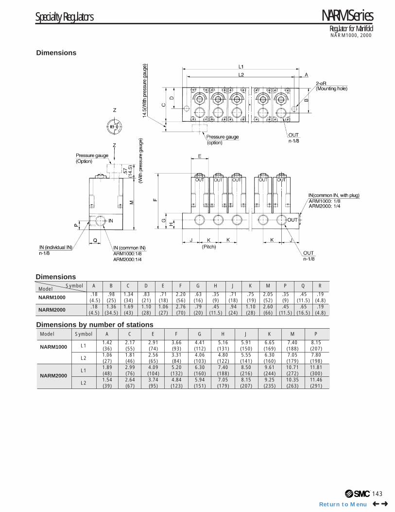
Symbol A B C D E F G H J K M P Q RModel
NARM1000.18 .98 1.34 .83 .71 2.20 .63 .35 .71 .75 2.05 .35 .45 .19 (4.5) (25) (34) (21) (18) (56) (16) (9) (18) (19) (52) (9) (11.5) (4.8)
NARM2000.18 1.36 1.69 1.10 1.06 2.76 .79 .45 .94 1.10 2.60 .45 .65 .19
(4.5) (34.5) (43) (28) (27) (70) (20) (11.5) (24) (28) (66) (11.5) (16.5) (4.8)
Dimensions
Dimensions
Dimensions by number of stationsModel Symbol A C E F G H J K M P
NARM1000 L11.42 2.17 2.91 3.66 4.41 5.16 5.91 6.65 7.40 8.15(36) (55) (74) (93) (112) (131) (150) (169) (188) (207)
L21.06 1.81 2.56 3.31 4.06 4.80 5.55 6.30 7.05 7.80(27) (46) (65) (84) (103) (122) (141) (160) (179) (198)
NARM2000L1
1.89 2.99 4.09 5.20 6.30 7.40 8.50 9.61 10.71 11.81(48) (76) (104) (132) (160) (188) (216) (244) (272) (300)
L21.54 2.64 3.74 4.84 5.94 7.05 8.15 9.25 10.35 11.46(39) (67) (95) (123) (151) (179) (207) (235) (263) (291)
➜➜Return to Menu
144
NARM Series Specialty Regulators
®
Regulator for ManifoldNARM2500, 3000
A modular type that can easily be mounted in a manifold station.
Optimal for central pressure control.
Pressure easily set using the new handle.One-touch lock system.
NARM3000
NARM2500
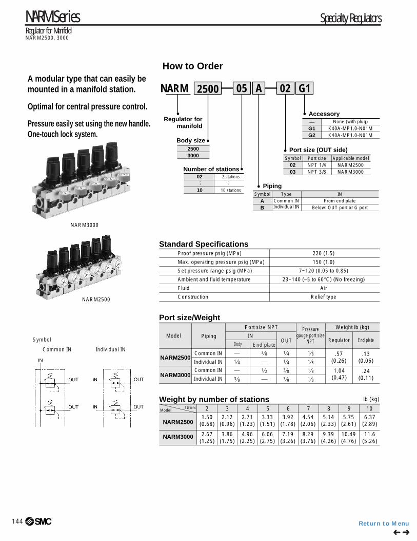
How to Order
NARM 2500 05 A
Regulator formanifold
Body size
Number of stations
Piping
Port size (OUT side)25003000
02 G1
02 2 stations
10 10 stations
Accessory—G1G2
None (with plug)
Symbol
AB
Symbol Port size
0203
NPT 1/4NPT 3/8
Applicable model
NARM2500NARM3000
TypeCommon IN
INFrom end plate
Below: OUT port or G port
K40A-MP1.0-N01MK40A-MP1.0-N01M
Standard Specifications
Port size/Weight
Weight by number of stations
Proof pressure psig (MPa)
Max. operating pressure psig (MPa)
Set pressure range psig (MPa)
Ambient and fluid temperature
Fluid
Construction
220 (1.5)
150 (1.0)
7~120 (0.05 to 0.85)
23~140 (–5 to 60°C) (No freezing)
Air
Relief type
Model Piping
Port size NPT Weight lb (kg)
INOUT
Pressuregauge port size
NPT
NARM2500
NARM3000
Common IN
Individual IN
Common IN
Individual IN
Regulator End plate
.57(0.26)
.13(0.06)
1.04(0.47)
.24(0.11)
1 43 8
1 41 4
3 81 2
3 83 8
1 8
1 8
1 8
1 8
NARM2500
NARM3000
StationsModel 2 3 4 5 6 7 8 9 10
lb (kg)
1.50(0.68)
2.67(1.25)
2.12(0.96)
3.86(1.75)
2.71(1.23)
4.96(2.25)
3.33(1.51)
6.06(2.75)
3.92(1.78)
7.19(3.26)
4.54(2.06)
8.29(3.76)
5.14(2.33)
9.39(4.26)
5.75(2.61)
10.49(4.76)
6.37(2.89)
11.6(5.26)
Individual IN
End plateSymbol
Common IN Individual INBody
➜➜Return to Menu

145
Specialty Regulators NARM Series
®
NARM2500
NARM3000
87
72.5
58
43.5
30
15
0 35.3 70.6
Sec
onda
ry P
ress
ure
(psi
g)
Flow (SCFM)
87
72.5
58
43.5
30
15
0 35.3 70.6 106
Sec
onda
ry P
ress
ure
(psi
g)
Flow (SCFM)
Precautions
Warning
Caution
Model Part no. A1.18(30)1.61(41)
136314
136414
NARM2500
NARM3000
B1.34(34)1.57(40)
2.76(70)2.97
(75.5)
.21(5.4).26
(6.5)
.61(15.4)
.31(8)
2.17(55)2.09(53)
.09(2.3).09
(2.3)
C D E F G
Option: Bracket assemblyIndividual IN type can be used as a single regulator.
Model Part no.
136313136413
NARM2500NARM3000
Dimensions
Hexagon socket head cap screw (M5 x 70)
Hexagon socket head cap screw (M6 x 85)
Qty.
44
NoteWith flat washer
With flat washer
Flow Characteristics Supply pressure: 100 psig
Pressure CharacteristicsMounting/Adjustment
The adjustment handle must be operated manually. Using a tool to turn the handle could lead to damage.Set up the regulator while verifying the pressure that is indicated on the primary and the secondary pressure gauges. Turning the handle excessively could damage the internal parts.
Release the lock to adjust the pressure. After the adjustment, engage the lock. Failure to observe this procedure could damage the handle or cause the secondary pressure to fluctuate.1) On the NARM2500, pull the adjustment
handle to release the lock and push the adjustment handle to engage the lock. If it does not lock easily, turn the handle slightly clockwise or counterclockwise before pushing it.
2) On the NARM3000, pull the adjustment handle to release the lock. (An orange colored line is provided at the bottom of the adjustment handle for visual checking.) Push the adjustment handle to engage the lock. If it does not lock easily, turn the handle slightly clockwise or counterclockwise; then, push it until the orange colored line is no longer visible.Turning the pressure adjustment handle clockwise increases the secondary pressure and turning it counterclockwise decreases the pressure.Make sure to check the primary pressure before setting the pressure. The secondary pressure must be set to 85% or less of the primary pressure. Failure to observe this procedure could cause the secondary pressure to fluctuate.In the case of the common IN type, supply pressure from the two IN ports from both ends. Failure to observe this procedure could lead to an excessive pressure drop.
2
1
Supply pressure 100 psigSecondary pressure 30 psigFlow rate .7 SCFM
Option: Mounting bolt ass'y
Be sure to read before handling.Refer to page 6 for Safety Instructions and precuations common to the products mentioned in this volume and refer to pages 7 and 8 for more detailed precautions of every series.
1
4
3
2
NARM2500
NARM3000
36.3
30
2215 43.5 72.5 101.5 130.5 159.5
Sec
onda
ry p
ress
ure
(psi
g)
Supply pressure (psig)
36.3
30
2215 43.5 72.5 101.5 130.5 159.5
Sec
onda
ry p
ress
ure
(ps
ig)
Supply pressure (psig)
➜➜Return to Menu

NARM Series Specialty RegulatorsRegulator for ManifoldNARM2500, 3000
Component Parts
No. Description MaterialPart no.
NBR
Brass/NBR
Stainless steel
NBR
NBR
NBR
NARM2500 NARM3000
1349161A
13639A
136310
11.5 X 8.5 X 1.5
P3
28 X 25 X 1.5
131515A
13649A
136410
14.5 X 10.5 X 2
P5
35 X 31 X 2
Diaphragm ass'y
Valve ass'y
Valve spring
Valve O-ring
O-ring
O-ring
3
4
5
6
7
8
Main PartsNo. Description Material Note
1
2
Body
Bonnet
Aluminum die casting
Polyacetal
Chromate/Platinum silver paintingComponent Qty.
1
1
1
1
1
2
21set
2
9
10
11
12
13
14
15
Regulator
End plate R
End plate L
O-ring
O-ring
Regulator NARM2500-A-N02 NARM2500-B-N02 NARM3000-A-N03
13636A
136312 136412
13646A13636B
(Except for O-ring)
13646B
(Except for O-ring)
NARM3000-B-N03
Common IN Individual IN Common IN Individual IN
Endplateass'y
Bracketass'y
Bra
cket Bracket A
Bracket BHexagon socket head cap screw
Bra
cket Bracket A
Bracket BHexagon socket head cap screw
2
21set
2
25003000
AB
How to Order(1) When adding n stations to ARM -∗ ∗ :
·Regulator n pcs.·Bracket ass'y n pcs.
(2) When ordering regulators, end plate assembly and bracket assembly are assembled to make the manifold of n stations.·Regulator n pcs.·Bracket ass'y n pcs.·End plate ass'y 1 pc.
Component Parts
No.
Part no.
Description
Assembly
NARM2500 NARM3000
Construction
146®
➜➜Return to Menu
147
Specialty Regulators NARM Series
®
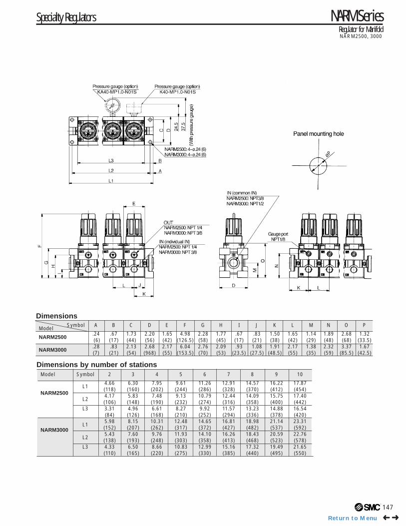
Regulator for ManifoldNARM2500, 3000
Model Symbol 2 3 4 5 6 7 8 9 10
NARM2500L1
4.66 6.30 7.95 9.61 11.26 12.91 14.57 16.22 17.87(118) (160) (202) (244) (286) (328) (370) (412) (454)
L24.17 5.83 7.48 9.13 10.79 12.44 14.09 15.75 17.40(106) (148) (190) (232) (274) (316) (358) (400) (442)
L3 3.31 4.96 6.61 8.27 9.92 11.57 13.23 14.88 16.54(84) (126) (168) (210) (252) (294) (336) (378) (420)
NARM3000L1
5.98 8.15 10.31 12.48 14.65 16.81 18.98 21.14 23.31(152) (207) (262) (317) (372) (427) (482) (537) (592)
L25.43 7.60 9.76 11.93 14.10 16.26 18.43 20.59 22.76(138) (193) (248) (303) (358) (413) (468) (523) (578)
L3 4.33 6.50 8.66 10.83 12.99 15.16 17.32 19.49 21.65(110) (165) (220) (275) (330) (385) (440) (495) (550)
øP
Dimensions
Dimensions by number of stations
Symbol A B C D E F G H I J K L M N O PModel
NARM2500.24 .67 1.73 2.20 1.65 4.98 2.28 1.77 .67 .83 1.50 1.65 1.14 1.89 2.68 1.32(6) (17) (44) (56) (42) (126.5) (58) (45) (17) (21) (38) (42) (29) (48) (68) (33.5)
NARM3000.28 .83 2.13 2.68 2.17 6.04 2.76 2.09 .93 1.08 1.91 2.17 1.38 2.32 3.37 1.67(7) (21) (54) (968) (55) (153.5) (70) (53) (23.5) (27.5) (48.5) (55) (35) (59) (85.5) (42.5)
➜➜Return to Menu