special types of diodes Tunnel diode(1)
24
-
Upload
03470719974 -
Category
Engineering
-
view
44 -
download
6
Transcript of special types of diodes Tunnel diode(1)


MADE BY GROUP 4
• BILAL HASSAN
• HAMZA ISMAIL MALIK
• ALI HASSAN ZAIDI
• MUHAMMAD ADNAN
• YOUNS NAQASH

TUNNEL DIODE

OUT LINESHISTORYDEFINITIONCONSTRUCTIONWORKINGAPPLICATION ADVANTAGE S AND DISADATAGES

HISTORY
• Tunnel Diode was invented in August 1957 by Leo Esaki.
• In 1973 he received the Nobel prize in physics for discovering the electron tunneling effect used .
• well into the microwave frequency region, made possible by the use of the quantum mechanical effect called tunneling.

Definition
• An extremely stable semiconductor diode, having a very narrow highly doped p-n junction, in which electrons travel across the junction by means of the tunnel effect.

Construction
• There are several steps for this which are given below
1. Firstly, it reduces the width of the depletion layer to anextremely small value (about 0.00001 mm). 2. Secondly, it reduces the reverse breakdown voltage to a very small value (approaching zero) with the result that the diode appears to be broken down for any reverse voltage.

construction3. Thirdly, it produces a negative resistance section on the V/I characteristic of the diode.It is called a tunnel diode because due to its extremely thin depletion layer, electrons are able to tunnel through the potential barrier at relatively low forward bias voltage (less than 0.05 V). Such diodes are usually fabricated from germanium, gallium-arsenide(GA As) and gallium antimonites (Gabs).

Tunnel diode symbol
Physical structure

V/I Characteristic
• As seen, forward bias produces immediate conduction i.e. as soon as forward bias is applied, significant current is produced.
• The current quickly rises touts peak value Ip when the applied forward voltage reaches a value Vp (point A ).

V/I Characteristic
•When forward voltage is increased further, diode current starts decreasing till it achieves its minimum value called valley current Iv corresponding to valley voltage Vv (point B).
• For voltages greater than Vv, current starts increasing again as in any ordinary junction diode.

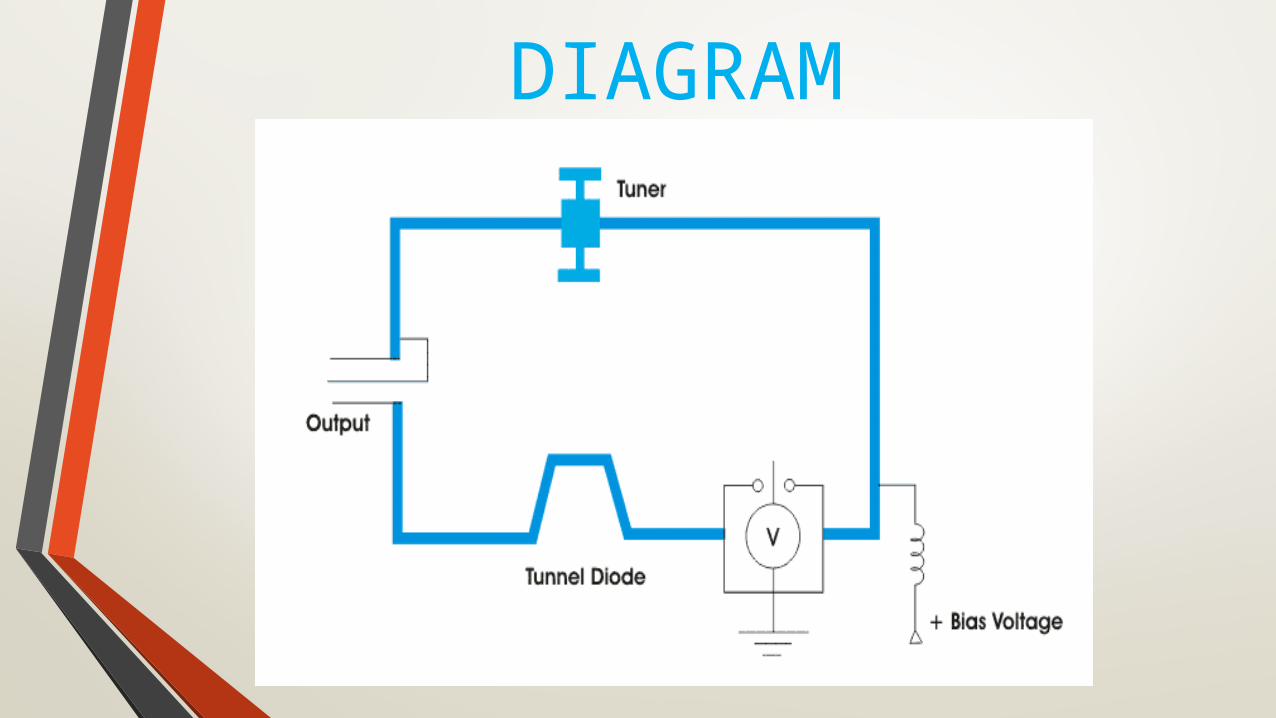
DIAGRAM

V/I Characteristic• As seen from Fig between the peak point A and valley point B,
current decreases with increase in the applied voltage.
• In other words, tunnel diode possesses negative resistance (— R N) in this region.
• In fact, this constitutes the most useful property of the diode. Instead of absorbing power, a negative resistance produces power.
• By offsetting losses in L and C components of a tank circuit, such a negative resistance permits oscillations.
V/I Characteristic
• Hence, a tunnel diode is used as a very high frequencyoscillator.
• Another point worth noting is that this resistance increases as we go from point A to B because as voltage is increased, current keeps decreasing which means that diode negative resistance keeps increasing.

Negative Resistance (– RN)
• It is the resistance offered by the diode within the negative resistance section of its characteristic. It equals the reciprocal of the slope of the characteristic in this region.It may also be found from the following relation
R N = − dV/dI.
• Its value depends on the semiconductor material used (varying from − 10 Ω to − 200 Ω).
DIAGRAM

Tunneling diode theory• At zero forward bias, the energy levels of conduction electrons in N-region of the junction are slightly out of alignment with the energy levels of holes in the P-region.
• As the forward voltage is slightly increased, electron levels start getting aligned with the hole levels on the other side of junction thus permitting some electrons to cross over. This kind of junction crossing is called tunneling.

Tunneling diode theory• As voltage is increased to peak voltage (VP), all
conduction band electrons in the N-region are able to cross over to the valence band in the P-region because the two bands are exactly aligned. Hence, maximum current (called peak current IP) flows in the circuit.
•After VP as the applied voltage is increased, current starts decreasing because the two bands start gradually getting out of alignment.

• It reaches minimum value (called valley current) when the two are totally out of alignment at a forward bias of VV (valley voltage).
• For voltages greater than VV, current starts increasing again exactly as it does in the case of an ordinary P-N junction diode.
• Tunneling is much faster than normal crossing which enables a tunnel diode to switch ON and OFF much faster than an ordinary diode. That is why a tunnel diode is extensively used in special applications requiring very fast switching speeds like high-speed computer memories and high frequency oscillators .
Backward diode applications
The characteristics of the backward diode make it suitable for a limited number of applications where other diodes may not perform as well.
• Detector :
The backward diode provides a linear detection characteristic for small signals. Additionally the fact that there is no charge storage in its mode of operation means that it can be used for signals with frequencies extending to 50 GHz and more
Backward diode applications
• Rectifier:
The diode is suitable for rectifying signals with peak voltages between about 0.1 and 0.6 volts.
• Switch:
In view of its speed of operation, the diode is sometimes used for very high speed switching applications.

Advatages and disadvantages
• The advantages of a tunnel diode are :
• 1. low noise
• 2. ease of operation
• 3. high speed
• 4. low power
• 5. Insensitivity to nuclear radiations

Advatages and disadvantages
1.The voltage range over which it can be operated properly is 1 V or less.
2.Being a two-terminal device, it provides no isolation between the input and output circuits

SGH