Special applications Particulars Useofan Useofa inconjunctionwiththe shifter or on frames with the...
20
48 max. 10 mm min. 6,5 mm min. 15mm Rohloff chain tensioner (Art.No. 8250) Tension capacity of 10 links Rohloff chain guide CC (Art.No. 8290) Particulars Use of an Use of a in conjunction with the shifter or on frames with the Usage of enclosed chainguard. carbon handlebar Eccentric BB adjustable dropouts Tuning parts The Rohloff AG will not be held responsible for accidents resulting from the mounting of the Rohloff shifter on carbon handlebars. Twist shifter Toxoholics Titanium sprockets Singlestar Titanium Twist shifter Rewel . Titanium axle plates Rewel www.rohloff.de >FAQs The chainguard rub against the hub shell. This rubbing effect could result in deep brush marks upon the hub shell, possibly eventually wearing completely through it! This damage could lead to accidents through oil leakage or even a complete blockage of the gear unit itself. The Rohloff Shifter is not approved for installation on any sort of carbon handlebar. It is especially important to use a concentric mounted chainring when utilizing an eccentric BB or adjustable dropouts, otherwise the chain tension could vary extremely. The chain tension should be set so that the chain has approximately 10mm play when lightly pushed from underneath and under no pressure. If using adjustable dropouts in collaboration with the internal gear mech, then it is important to check that there is enough room for the cable adjusters to accomodate the moving of the rear wheel as the chain wears/stretches.(if not, the housing may have to be shortened). (Imperial) with engraved gear indicator from “ ” is 100% compatible with the Rohloff twist shifter housing, it can be shortened to the desired length and is delivered with a corresponding left grip. from “ ” are compatible. Make sure to check the min. chainring/sprocket ratios from “ ” rotates over 360° and does not incorporate a bedstop from “ ” are not appropriate for tandem use or for fully loaded touring bikes. Further information over these parts is available on our homepage under: must not Rohloff Rohloff SPEEDHUB Special applications
Transcript of Special applications Particulars Useofan Useofa inconjunctionwiththe shifter or on frames with the...

48
max.10 mm
min. 6,5 mm min. 15mm
Rohloff chain tensioner (Art.No. 8250)
Tension capacity of 10 links
Rohloff chain guide CC (Art.No. 8290)
Particulars
Use of an
Use of a in conjunction with the shifter
or on frames with the
Usage of
enclosed chainguard.
carbon handlebar
Eccentric BB adjustable dropouts
Tuning parts
The Rohloff AG will notbe held responsible for accidents resulting from the mounting of the Rohloff shifter on carbonhandlebars.
Twist shifter Toxoholics
Titanium sprockets SinglestarTitanium Twist shifter Rewel .Titanium axle plates Rewel
www.rohloff.de > FAQs
The chainguard rub against the hub shell. This rubbing effect could result in deep brush marks upon thehub shell, possibly eventually wearing completely through it! This damage could lead to accidents through oilleakage or even a complete blockage of the gear unit itself.
The Rohloff Shifter is not approved for installation on any sort of carbon handlebar.
It is especially important to use a concentric mounted chainring when utilizing an eccentric BB or adjustabledropouts, otherwise the chain tension could vary extremely. The chain tension should be set so that the chain hasapproximately 10mm play when lightly pushed from underneath and under no pressure.If using adjustable dropouts in collaboration with the internal gear mech, then it is important to check that there isenough room for the cable adjusters to accomodate the moving of the rear wheel as the chain wears/stretches.(ifnot, the housing may have to be shortened).
(Imperial) with engraved gear indicator from “ ” is 100% compatible with the Rohlofftwist shifter housing, it can be shortened to the desired length and is delivered with a corresponding left grip.
from “ ” are compatible. Make sure to check the min. chainring/sprocket ratiosfrom “ ” rotates over 360° and does not incorporate a bedstop
from “ ” are not appropriate for tandem use or for fully loaded touring bikes.
Further information over these parts is available on our homepage under:
must not
Rohloff
Rohloff SPEEDHUB
Special applications
49
Mounting
1. Package contents
2. The wheel
3. Mounting additional parts (according to the version)
4. Cable routing and axle plate alignment
5. Mounting the wheel
The following sequences are useful for the mounting of the
1.1 Checking the package contents ............................................................................ 51
1.2 Checking the contents of the small parts bag ...................................................... 53
Wheelbuilding ...................................................................................................... 55
3.1 Standard long torque arm ..................................................................................... 56
3.2 Crankset ............................................................................................................... 57
3.3 DH chain guide (accessory for downhill) ............................................... 58
3.4 OEM2 mounting with a support bolt ................................................................... 59
3.5 OEM2 mounting with
3.6 Brake discs ........................................................................................................... 60
4.1.1 Internal gear mech via brake boss ........................................................................ 61
4.1.2 Internal gear mech via chainstay .......................................................................... 62
4.2.1 External gear mech OEM/OEM2 ......................................................................... 63
4.2.2 External gear mech with long torque arm ............................................................ 63
4.3 Axle plate alignment ............................................................................................ 64
5.1.1 with a long torque arm
Mounting (CC versions) ...................................................................................... 65
Mounting (TS versions) ....................................................................................... 66
5.1.2 with an OEM axle plate ......................................... 67
5.1.3 with an OEM2 axle plate ....................................... 67
5.2 Chain tensioner
5.2.1 chain tensioner ........................................................................................ 68
5.2.2 DH chain tensioner (accessory for downhill) .......................................... 69
5.3 The chain
5.3.1 Mounting with a chain tensioner .......................................................................... 70
5.3.2 Mounting without a chain tensioner .................................................................... 70
5.4 chain guide CC ........................................................................................ 71
Rohloff SPEEDHUB 500/14
Rohloff
Rohloff SPEEDBONE ...................................................... 59
Rohloff SPEEDHUB 500/14
Rohloff SPEEDHUB 500/14
Rohloff SPEEDHUB 500/14
Rohloff
Rohloff
Rohloff
Mounting
50
6. Twist shifter
7. Cable routing
8. First oil fill
Mounting of the twist shifter ................................................................................ 73
7.1 Shifter cables ........................................................................................................ 75
7.2. Internal gear mech
7.2.1 Cable routing via the brake boss .......................................................................... 76
7.2.2 Cable routing via the chainstay ............................................................................ 79
7.3 External gear mech
7.3.1 Cable routing via the chainstay ............................................................................ 80
7.3.2 Cable routing via the top tube .............................................................................. 83
7.4 Adjusting the gear display ................................................................................... 83
Filling with oil ...................................................................................................... 84
Mounting

51
1.1 Checking the package contents
CC
CC
OE
M
CC
DB
CC
DB
OE
M
CC
EX
CC
EX
OE
M
TS
TS
OE
M
TS
DB
TS
DB
OE
M
TS
EX
TS
EX
OE
M
Long torque arm 6 l l l l l l
Chain tensioner 7 l l l
In the package will be:Rohloff SPEEDHUB 500/14
- in the desired version
- Bottle of
- Small parts bag
- Two shifter cables consisting of bowden cable, nylon liner and cable housing
- Twist shifter
In the package could also be a long torque arm and/or a chain tensioner. Thefollowing table shows in which package these could befound.
Rohloff SPEEDHUB 500/14
Rohloff SPEEDHUB OIL
Rohloff
1
2
3
4
5
- Handbook (Art.Nr. 8295)
- Guarantee card
- Oil fill reminder
Rohloff SPEEDHUB 500/14
Rohloff SPEEDHUB 500/14
8
9
Mounting
52
3
4
5 6 7
1
2
98
Mounting

53
1.2 Checking the contents of the small parts bag
There is a bag of small parts within the package. These will be
needed in order to mount the to the bike itself. The contents of the
bag depend upon which version of the is contained within the
package.
Rohloff SPEEDHUB 500/14
Rohloff SPEEDHUB 500/14
Rohloff SPEEDHUB 500/14
All the possible parts in this bag are shown with a number on the following side . Under that is
a table showing which parts are to be found in the bag depending upon which version of the
is contained within the package.
Example:
CC EX OEM:
In this bag there will be eight cable housing caps (#12), five chainring washers (#17), an oil
filling tube (#22) and an EX cable box (#23).
Rohloff SPEEDHUB 500/14
Rohloff SPEEDHUB 500/14
Mounting
54
14
18
1312
10
1615
19
20
22
24
23
17
11
21
# Part
s
CC
CC
OE
M
CC
DB
CC
DB
OE
M
CC
EX
CC
EX
OE
M
TS
TS
OE
M
TS
DB
TS
DB
OE
M
TS
EX
TS
EX
OE
M
10 2 Axle nuts M10x1 l l l l l l
11 2 Washers for the TS axle l l l l l l
12 8 Cable housing caps l l l l l l l l l l l l
13 1 Spacer 6,5x10x5,5 for the cable guide l l l l
14 1 Cable guide 13° with adjusters & mounting bolt l l l l
15 2 Clamps l l l
16 1 Torque arm clamp l l l
17 5 Chainring spacers l l l l l l l l l l l l
18 2 Female bayonet connectors l l l l
19 2 Mounting bolts M8x0,75 l l l l
4 Mounting bolts M8x0,75 l l
6 Mounting bolts M8x0,75 l l
20 2 Threaded bushes M8x0,75 l l l l l l
21 2 Washers l l l l l l
22 1 Oil filling tube l l l l l l l l l l l l
23 1 EX cable box l l l l l l l l
24 1 Quick release block & locating fork for torque arm l l l
Mounting

55
2
EU
1
3
FR
4
P OI NTE R
Spoke head
Hub cap screw
Leadingspoke(inwardhead)
Trailing spoke(outwardhead)
ATTE NT I ON
Mounting
2. The wheel
Wheel lacingThe number of times that the spo-
kes are crossed over depends enti-
rely upon the size of the rim.
All rims in dia-
meter
pattern. All
wheels must be laced
pattern.
Due to the high torsional strength
of the hub casing, the use of a re-
versed lacing pattern on the brake
disk side (DB versions) is not ne-
cessary.
larger than 24"
must be laced in a two
cross 24" and smaller
sized up in a
one cross
Further detailed information
with regards to wheel lacing can
be found in the Appendix.
The leading spokes are laced so
that the spoke head always faces in-
wards.The trailing spokes are laced
so that the spoke head always faces
outwards. All spokes should be
crossed over each other.
Rims are manufacturered in dife-
rent ways. The type of nipple hole
pattern must be determined before
lacing the wheel as this will requi-
re a different lacing method to be
followed. In picture 1 the
European nipple hole pattern (EU)
is shown. The first spoke hole be-
hind the valve hole lies to the di-
rection of the right hand hub flange
(pay attention to the rotational di-
rection of the rim).
The wheel lacing method is deter-
mined by the nipple hole pattern.
The correct lacing method for both
types of hole pattern can be found
in the appendix.
Rotating the hub whilst wheelbuil-
ding will be easier when the
Rohloff SPEEDHUB 500/14 is in
gear #11. This gear can be selected
by pulling the hub cables (internal
gear mech), or turning the hexago-
nal peg on the gear transfer box
with an 8mm wrench (external ge-
ar mech).
Rot a
tion d
irection
In picture 2 the French nipple hole
pattern (FR) is shown. The first
spoke hole behind the valve hole
lies to the direction of the left hand
hub flange (pay attention to the ro-
tational direction of the rim).
If the spoke holes of the rim are all
centrally drilled, then the lacing
method for a European nipple hole
pattern should be followed (see ap-
pendix).
Spokes must not cross directly over
the hub cap fixing screws on
wheels which are 24” or smaller in
diameter!
Rot a
tion d
irection
Valve hole Valve hole
56
C
B
A
E
D
E
G
H
F
1 2
3 4
F
G
H
Locating fork
Securing pin with circlip
Circlip
A
B
C
D
E
Threaded bush
Washer
Mounting bolt
Axle plate (CC or TS)
Long torque arm
On the CC versions, the locating
fork must also be attached to the
torque arm. Place the forked end
over the torque arm, push the
securing pin through the two parts
and secure the other end in place
with the circlip. TS Versions must
have a torque arm clamp mounted
instead of the locating fork.
Make sure that both circlips sit cor-
rectly onto the securing pin.
Push the threaded bushes through
the torque arm from behind. Place
a washer over each of the bushes
and then the axle plate over these
washers (pictures 1 and 2 show the
TS version). Secure the two parts
together with the mounting bolts.
(M8 0.75 - 5mm allen key,
tightening torque: 7Nm/61in.lbs.).
x
3. Mounting additional parts
The comes with additional parts according to the corresponding version. These parts
must be mounted first.
Rohloff SPEEDHUB 500/14
3.1 Standard long torque arm
All versions not carrying the codes OEM or OEM2 come included with the long torque
arm for supporting the torque. This must be mounted to the axle plate.
Rohloff SPEEDHUB 500/14
ATTE NT I ON
Mounting
57
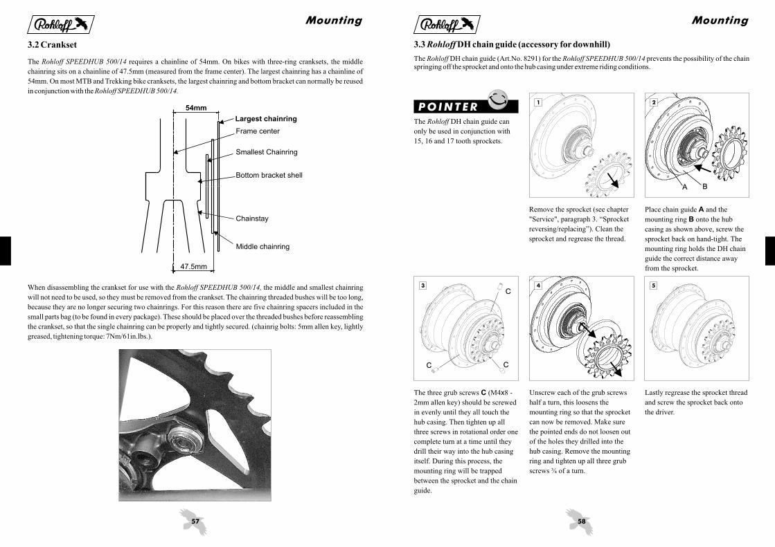
When disassembling the crankset for use with the the middle and smallest chainring
will not need to be used, so they must be removed from the crankset. The chainring threaded bushes will be too long,
because they are no longer securing two chainrings. For this reason there are five chainring spacers included in the
small parts bag (to be found in every package). These should be placed over the threaded bushes before reassembling
the crankset, so that the single chainring can be properly and tightly secured. (chainrig bolts: 5mm allen key, lightly
greased, tightening torque: 7Nm/61in.lbs.).
Rohloff SPEEDHUB 500/14,
3.2 Crankset
The requires a chainline of 54mm. On bikes with three-ring cranksets, the middle
chainring sits on a chainline of 47.5mm (measured from the frame center). The largest chainring has a chainline of
54mm. On most MTB and Trekking bike cranksets, the largest chainring and bottom bracket can normally be reused
in conjunction with the
Rohloff SPEEDHUB 500/14
Rohloff SPEEDHUB 500/14.
Largest chainring
Middle chainring
Frame center
Smallest Chainring
Bottom bracket shell
Chainstay
54mm
47.5mm
Mounting
58
BA
C
CC
1 2
4 53
Unscrew each of the grub screws
half a turn, this loosens the
mounting ring so that the sprocket
can now be removed. Make sure
the pointed ends do not loosen out
of the holes they drilled into the
hub casing. Remove the mounting
ring and tighten up all three grub
screws ¾ of a turn.
Lastly regrease the sprocket thread
and screw the sprocket back onto
the driver.
Remove the sprocket (see chapter
"Service", paragraph 3. “Sprocket
reversing/replacing”). Clean the
sprocket and regrease the thread.
Place chain guide and the
mounting ring onto the hub
casing as shown above, screw the
sprocket back on hand-tight. The
mounting ring holds the DH chain
guide the correct distance away
from the sprocket.
A
B
The three grub screws (M4 8 -
2mm allen key) should be screwed
in evenly until they all touch the
hub casing. Then tighten up all
three screws in rotational order one
complete turn at a time until they
drill their way into the hub casing
itself. During this process, the
mounting ring will be trapped
between the sprocket and the chain
guide.
C x
P OI NTE RThe DH chain guide can
only be used in conjunction with
15, 16 and 17 tooth sprockets.
Rohloff
3.3 DH chain guide (accessory for downhill)Rohloff
The DH chain guide (Art.No. 8291) for the prevents the possibility of the chainspringing off the sprocket and onto the hub casing under extreme riding conditions.
Rohloff Rohloff SPEEDHUB 500/14
Mounting

59
1 2 3
321
Mounted
view from inside the frame.
Rohloff SPEEDBONE, Mounted
view from outside the frame.
Rohloff SPEEDBONE,Rohloff SPEEDBONE (Art.No.
8550) with securing bolts.
3.5 OEM2 mouting with a Rohloff SPEEDBONE
The is mounted from the outer side of the frame and secured through the disc brake mounts
into the brake caliper (paying attention to the brake manufacturers tightening torques). The original caliper securing
bolts will be too short to mount through the and should, therefore, be replaced by the long
securing bolts.
Rohloff SPEEDBONE
Rohloff SPEEDBONE
Rohloff SPEEDBONE
3.4 OEM2 mounting with a support bolt
The support bolt assembly for OEM2 mounting consists of a bolt (M6 16), a washer and a locknut. It is secured
through the disc brake mounting hole of the dropout from the inside (tightening torque: 8Nm/71in.lbs.).
x
Mounted support bolt,
view from inside the frame.
Mounted support bolt,
view from outside the frame.
Support bolt
CC OEM2 axle plate
LocknutWasher
Supportbolt
Washer
Locknut
Mounting
60
L
M
4 5
1 2 3
3.6 Brake discs
The uses a disc mount with a central diameter of 52mm and a stable four bolt mounting
system which in turn has a diameter of 65mm. The special brake disc must be additionaly ordered.
Rohloff SPEEDHUB 500/14
Rohloff
The external transfer box should
not be removed as the gears within
could fall out of synchronisation.
See chapter “Service”, paragraph
5. "Exchanging of the gear mech".
Remove the five axle plate screws
(M4 25 - Torx TX20) along with
the axle plate. Secure the external
transfer box in place with one of
these axle plate screws .
x
L
Place the brake disc over the
external transfer box and locate
over the center disc mounting. Pay
close attention to the directional
rotation of the brake disc!
Place the four mounting bolts
into position and screw them in
tightly (M8 0.75 8.5 - 5mm allen
key, tightening torque:
7Nm/61in.lbs.). Remove the axle
plate screw from the external
transfer box and then replace all
five axle plate screws through the
axle plate itself and secure them
back tightly into the hub axle
(M4 25 - Torx TX20, tightening
torque:
M
L
x x
x
On OEM versions, the removal of
the axle plate is not necessary
when the axle plate lies direcly
over the external transfer box (Pic
4). The brake disc can be mounted
directly over these two
components (Pic 5).
ATTE NT I ON
Mounting
61
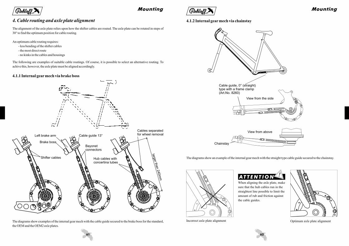
4. Cable routing and axle plate alignment
The alignment of the axle plate relies upon how the shifter cables are routed. The axle plate can be rotated in steps of
30° to find the optimum position for cable routing.
An optimum cable routing requires:
- less bending of the shifter cables
- the most direct route
- no kinks in the cables and housings
The following are examples of suitable cable routings. Of course, it is possible to select an alternative routing. To
achive this, however, the axle plate must be aligned accordingly.
4.1.1 Internal gear mech via brake boss
The diagrams show examples of the internal gear mech with the cable guide secured to the brake boss for the standard,
the OEM and the OEM2 axle plates.
Brake boss
Left brake arm
Bayonetconnectors
Cables separatedfor wheel removalCable guide 13°
Hub cables withconcertina tubes
Shifter cables
larg
er th
an 2
40m
m
Mounting
62
ATTE NT I ON
4.1.2 Internal gear mech via chainstay
The diagrams show an example of the internal gear mech with the straight type cable guide secured to the chainstay.
When aligning the axle plate, make
sure that the hub cables run in the
straightest line possible to limit the
amount of rub and friction against
the cable guides.
Incorrect axle plate alignment Optimum axle plate alignment
Chainstay
View from above
Cable guide, 0° (straight)type with a frame clamp(Art.No. 8260)
View from the side
Mounting

63
A
B
D
C
4.2.1 External gear mech OEM/OEM2
The diagrams above show the external gear mech with the cable routing via the chainstay for use with the OEM2
axle plate and the OEM axle plate .A B
4.2.2 External gear mech with long torque arm
The diagrams above show the external gear mech in combination with the standard axle plate and the long torque arm.
When the external transfer box needs to be in the position shown in diagram , then the axle plate must be secured to
the inside of the long torque arm.
D
Mounting
64
321
4.3Aligning of the axle plate
To align (rotate) the axle plate, all axle plate screws (M4 25, Torx TX20) must first be removed. Rotate the axle plate
into the desired position and then reinsert the axle plate screws through the axle plate into the hub axle. Secure them
tightly (tightening torque: 3Nm/25in.lbs.).
To hold the axle in position (when removing the axle plate screws), use a 10mm wrench on the OEM and OEM2
versions or simply hold the long torque arm tightly on the standard axle plate versions (see pictures below).
x
OEM axle plate: Hold the support
block with a 10mm wrench while
loosening/tightening the axle plate
screws.
Standard axle plate with long tor-
que arm: Hold the torque arm
tightly while loosening/tightening
the axle plate screws.
OEM2 axle plate: Hold the fork
leg with a 10mm wrench while loo-
sening/tightening the axle plate
screws.
Mounting
65
654
321
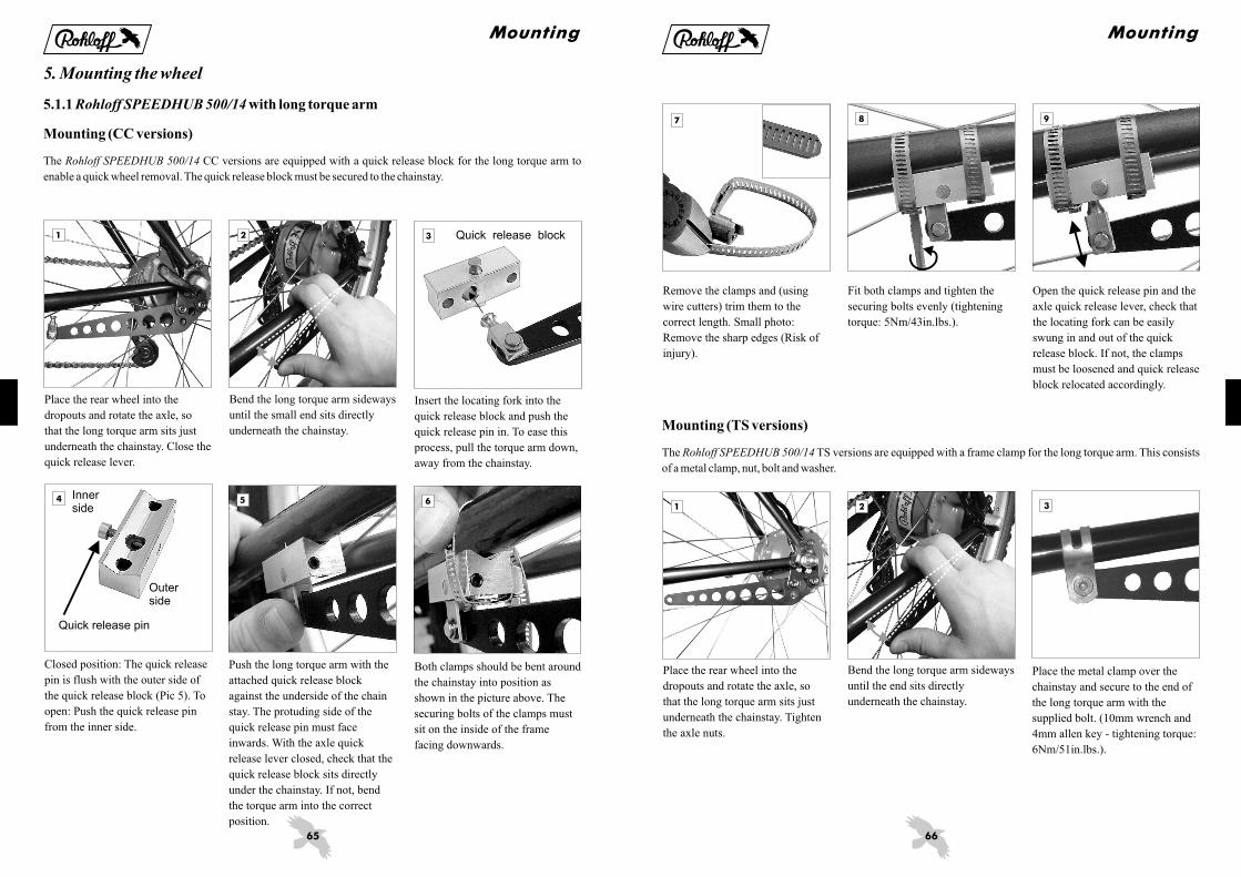
Bend the long torque arm sideways
until the small end sits directly
underneath the chainstay.
Place the rear wheel into the
dropouts and rotate the axle, so
that the long torque arm sits just
underneath the chainstay. Close the
quick release lever.
5. Mounting the wheel
5.1.1 with long torque arm
Mounting (CC versions)
Rohloff SPEEDHUB 500/14
The CC versions are equipped with a quick release block for the long torque arm to
enable a quick wheel removal. The quick release block must be secured to the chainstay.
Rohloff SPEEDHUB 500/14
Push the long torque arm with the
attached quick release block
against the underside of the chain
stay. The protuding side of the
quick release pin must face
inwards. With the axle quick
release lever closed, check that the
quick release block sits directly
under the chainstay. If not, bend
the torque arm into the correct
position.
Closed position: The quick release
pin is flush with the outer side of
the quick release block (Pic 5). To
open: Push the quick release pin
from the inner side.
Insert the locating fork into the
quick release block and push the
quick release pin in. To ease this
process, pull the torque arm down,
away from the chainstay.
Both clamps should be bent around
the chainstay into position as
shown in the picture above. The
securing bolts of the clamps must
sit on the inside of the frame
facing downwards.
Quick release block
Outerside
Quick release pin
Innerside
Mounting
66
321
987
Remove the clamps and (using
wire cutters) trim them to the
correct length. Small photo:
Remove the sharp edges (Risk of
injury).
Fit both clamps and tighten the
securing bolts evenly (tightening
torque: 5Nm/43in.lbs.).
Open the quick release pin and the
axle quick release lever, check that
the locating fork can be easily
swung in and out of the quick
release block. If not, the clamps
must be loosened and quick release
block relocated accordingly.
Mounting (TS versions)
The TS versions are equipped with a frame clamp for the long torque arm. This consists
of a metal clamp, nut, bolt and washer.
Rohloff SPEEDHUB 500/14
Place the metal clamp over the
chainstay and secure to the end of
the long torque arm with the
supplied bolt. (10mm wrench and
4mm allen key - tightening torque:
6Nm/51in.lbs.).
Bend the long torque arm sideways
until the end sits directly
underneath the chainstay.
Place the rear wheel into the
dropouts and rotate the axle, so
that the long torque arm sits just
underneath the chainstay. Tighten
the axle nuts.
Mounting

67
Rohloff SPEEDBONE
5.1.2 with OEM axle plateRohloff SPEEDHUB 500/14
When mounting the wheel, the axle peg must be inserted into the long dropout slot first, followed by the support
block. Before closing the quick release lever (CC versions) or tightening the axle nuts (TS versions), check that both
axle pegs are sitting correctly within the dropout slots.
5.1.3 with OEM2 axle plateRohloff SPEEDHUB 500/14
When mouting the wheel, the OEM2 axle plate seat must locate itself around the support bolt or the support peg of the
. Before closing the quick release lever (CC versions) or tightening the axle nuts (TS versions),
check that both axle pegs are sitting correctly within the dropout slots and that the axle plate seat sits correctly around
the support bolt/peg.
Rohloff SPEEDBONE
Axle plate seat
Support bolt
OEM dropout
Axle peg
Mounting
Support bolt
68
A
1 2 3
4 5
A
B
ATTE NT I ON
The chain tensioner comes
with a mounting bolt and four
distancing washers (3 1mm, 1
3mm). With the distancing
washers, it is possible to distance
the chain tensioner 1mm to
6mm away from the frame.
Rohloff
Rohloff
x x
Make sure that the upper jockey
wheel is correctly spaced with the
distancing washers, so that it sits di-
rectly underneath the sprocket (ar-
rowed).
The table shows the required dis-
tance to be filled by distancing
washers in relation to the dropout
thickness and the chainline used.
When mounting the chain
tensioner in this correct distance
from the dropout, it is guaranteed
that the jockey wheels sit directly
underneath the sprocket.
B
Rohloff
Secure the chain tensioner,
so that the end stop peg sits
against the back of the gear hanger.
(5mm allen key, tightening torque:
8Nm/70in.lbs., lightly grease the
mounting bolt).
Rohloff
A
On dropouts thinner than 7mm, the
use of the 13 tooth sprocket (chain-
line 58mm) will require the use of
the longer mounting bolt. This is
available separately (Art.No 8255).
5.2 Chain tensioner
5.2.1 chain tensionerRohloff (Art.No. 8250)
The chain tensioner has a tension capacity of 10 chain links. It is mounted to the derailleur hanger. The ap-
propriate chainline is adjusted by the use of the supplied washers.
Rohloff
Dropout
Mountingbolt
Distancingwashers
A [mm] B [mm] B [mm]
4 6 10
5 5 9
6 4 8
7 3 7
8 2 6
9 1 5
10 0 4
Chainline54mm
Chainline58mm
Dropoutthickness
Mounting
69
1m
m
543
21
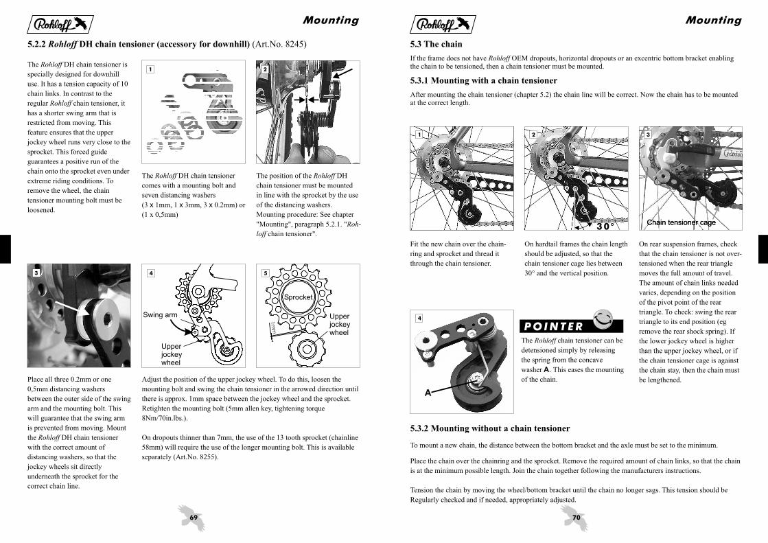
The DH chain tensioner
comes with a mounting bolt and
seven distancing washers
(3 1mm, 1 3mm, 3 0.2mm) or
(1 x 0,5mm)
Rohloff
x x x
The position of the DH
chain tensioner must be mounted
in line with the sprocket by the use
of the distancing washers.
Mounting procedure: See chapter
"Mounting", paragraph 5.2.1. "
chain tensioner".
Rohloff
Roh-
loff
Adjust the position of the upper jockey wheel. To do this, loosen the
mounting bolt and swing the chain tensioner in the arrowed direction until
there is approx. 1mm space between the jockey wheel and the sprocket.
Retighten the mounting bolt (5mm allen key, tightening torque
8Nm/70in.lbs.).
On dropouts thinner than 7mm, the use of the 13 tooth sprocket (chainline
58mm) will require the use of the longer mounting bolt. This is available
separately (Art.No. 8255).
Place all three 0.2mm or one
0,5mm distancing washers
between the outer side of the swing
arm and the mounting bolt. This
will guarantee that the swing arm
is prevented from moving. Mount
the DH chain tensioner
with the correct amount of
distancing washers, so that the
jockey wheels sit directly
underneath the sprocket for the
correct chain line.
Rohloff
5.2.2 DH chain tensioner (accessory for downhill)Rohloff (Art.No. 8245)
The DH chain tensioner is
specially designed for downhill
use. It has a tension capacity of 10
chain links. In contrast to the
regular chain tensioner, it
has a shorter swing arm that is
restricted from moving. This
feature ensures that the upper
jockey wheel runs very close to the
sprocket. This forced guide
guarantees a positive run of the
chain onto the sprocket even under
extreme riding conditions. To
remove the wheel, the chain
tensioner mounting bolt must be
loosened.
Rohloff
Rohloff
Swing arm
Upperjockeywheel
Upperjockeywheel
Sprocket
Mounting
70
3 0 °
A
11 3
4
2
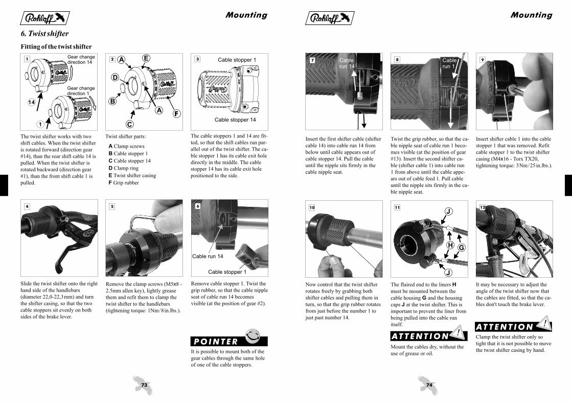
5.3.2 Mounting without a chain tensioner
To mount a new chain, the distance between the bottom bracket and the axle must be set to the minimum.
Place the chain over the chainring and the sprocket. Remove the required amount of chain links, so that the chain
is at the minimum possible length. Join the chain together following the manufacturers instructions.
Tension the chain by moving the wheel/bottom bracket until the chain no longer sags. This tension should be
Regularly checked and if needed, appropriately adjusted.
On hardtail frames the chain length
should be adjusted, so that the
chain tensioner cage lies between
30° and the vertical position.
On rear suspension frames, check
that the chain tensioner is not over-
tensioned when the rear triangle
moves the full amount of travel.
The amount of chain links needed
varies, depending on the position
of the pivot point of the rear
triangle. To check: swing the rear
triangle to its end position (eg
remove the rear shock spring). If
the lower jockey wheel is higher
than the upper jockey wheel, or if
the chain tensioner cage is against
the chain stay, then the chain must
be lengthened.
5.3 The chain
5.3.1 Mounting with a chain tensioner
If the frame does not have OEM dropouts, horizontal dropouts or an excentric bottom bracket enablingthe chain to be tensioned, then a chain tensioner must be mounted.
After mounting the chain tensioner (chapter 5.2) the chain line will be correct. Now the chain has to be mountedat the correct length.
Rohloff
Fit the new chain over the chain-
ring and sprocket and thread it
through the chain tensioner.
The chain tensioner can be
detensioned simply by releasing
the spring from the concave
washer This eases the mounting
of the chain.
Rohloff
A.
Chain tensioner cage
P OI NTE R
Mounting
Chain tensioner cage

71
A
A
A
A
1
3 42
5.4 chain guide CCRohloff (Art.No. 8290)
The chain guide CC prevents the chain from springing off the chainring. The chain guide CC is
adjustable for chainlines (distance between frame center and chain center) from 52mm to 62mm.
Rohloff Rohloff
To mount the chain guide
CC to a seat tube with a diameter
smaller than 36mm, one of the
three supplied shims will have to
be used. The table shows the cor-
rect shim for the different seat tube
diameters.
Rohloff Clip the shim over the seat tube at
the position level with the top of
the chainring.
For the extreme downhill use, a
special downhill chain guide for
the hub sprocket is recommended
(Art.No. 8291).
The diagram above shows the chain guide CC mounted with all
mounting parts shown. The number/type of distancing washers and shims
required varies depending on the frame. Therefore, a few measurements
must be taken in order to mount the chain guide CC correctly.
Rohloff
Rohloff
Firstly the seat tube diameter has
to be measured at the point level
with the top of the chainring.
Hexagonal nut
Clamp bracket
Rear distance bush
Right guide plate Left guide plate
Shim
Distancing washers
Threaded bush
M4x35(3mm allen key3Nm/25in.lbs.)
Front distance bush
Seattube
Tubediameter Shim
Seattube
Seat tube
Tube
diameter Shim
Ø28,7 Ø28,7
Ø32 Ø32
Ø35 Ø35
P OI NTE R
Mounting
72
10
20
30
40
X X
Ø28,7mm Ø32,0mm Ø35,0mm
5mm
5
8 97
ATTE NT I ON
The distance between the seat
tube with shim and the inner side
of the chainring determines how
many distancing washers will need
to be fitted. This is shown in the
table.
X Example: X=35mm
A 1mm distancing washer and a
2mm distancing washer are needed
between the front and the rear
threaded bushes and the left guide
plate.
The number and thickness of the
distancing washers must be the
same on both threaded bushes.
Mount the clamp brackets either
side of the seat tube by screwing
the bolts (M4 35 - Torx TX20)
through the clamp brackets into the
lightly greased threaded bushes of
the pre-assembled chain guide.
Locate the gap of the shim
between the two clamp brackets.
x
The chainguide is mounted with
the appropriate number and size of
distancing washers up to the point
shown in the diagram above.
(M4 20 and M4 35 - Torx TX20,
tightening torque: 3Nm/25in.lbs.).
x x
The rear distance bush (arrowed)
can now be mounted using a
lightly greased countersunk head
bolt (M4 20 - Torx TX20,
tightening torque 3Nm/25in.lbs.)
and secured into the hexagonal nut
below the upper chain run. Slide
the chain guide down the seat tube
until there is approx. 5mm between
the rear distance bush and the teeth
of the chainring. Make sure the
chain runs parallel and central
between the two guide plates
(distances , Pic 1).
x
A
X (mm)distancing
1mm
33 1 0
34 0 1
35 1 1
36 0 2
37 1 2
38 0 3
39 1 3
40 0 4
41 1 4
42 2 4Chainring
Left guide plate(3 holes)
Right guide plate(2 holes)
M4x35
Distancingwashers
Threaded bush
M4x20(TX20, 3Nm/25in.lbs.)
M4x35(Torx TX20,3Nm/25in.lbs.)
Mounting
washer
2mm
washerdistancing
73
654
32
1
14
1 E
F
A
A
D
C
B
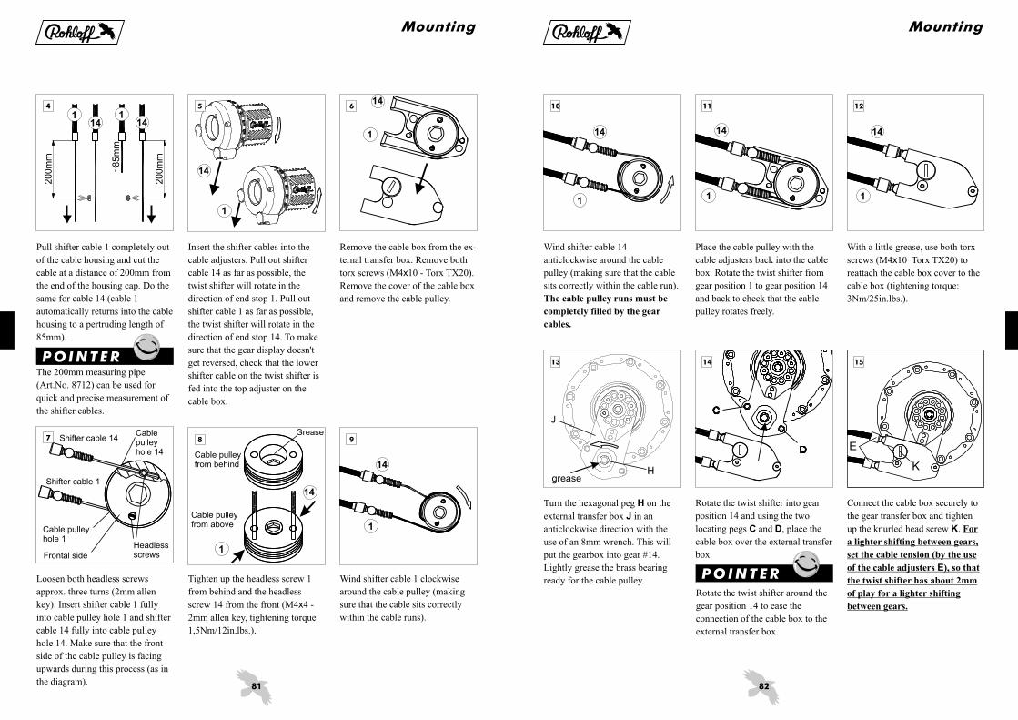
6. Twist shifter
Fitting of the twist shifter
A
B
C
Clamp screws
Cable stopper 1
14Cable stopper
Clamp ring
Twist shifter casing
Grip rubber
D
E
F
The twist shifter works with two
shift cables. When the twist shifter
is rotated forward (direction gear
#14), than the rear shift cable 14 is
pulled. When the twist shifter is
rotated backward (direction gear
#1), than the front shift cable 1 is
pulled.
The cable stoppers 1 and 14 are fit-
ted, so that the shift cables run par-
allel out of the twist shifter. The ca-
ble stopper 1 has its cable exit hole
directly in the middle. The cable
stopper 14 has its cable exit hole
positioned to the side.
Slide the twist shifter onto the right
hand side of the handlebars
(diameter 22,0-22,3mm) and turn
the shifter casing, so that the two
cable stoppers sit evenly on both
sides of the brake lever.
Remove the clamp screws (M5 8 -
2.5mm allen key), lightly grease
them and refit them to clamp the
twist shifter to the handlebars
(tightening torque: 1Nm/8in.lbs.).
x Remove cable stopper 1. Twist the
grip rubber, so that the cable nipple
seat of cable run 14 becomes
visible (at the position of gear #2).
Cable run 14
Cable stopper 1
Cable stopper 1Gear changedirection 14
Gear changedirection 1
Cable stopper 14
Twist shifter parts:
Mounting
It is possible to mount both of the
gear cables through the same hole
of one of the cable stoppers.
P OI NTE R
74
J
H G
J
8 9
10 11 12
7
Insert the first shifter cable (shifter
cable 14) into cable run 14 from
below until cable appears out of
cable stopper 14. Pull the cable
until the nipple sits firmly in the
cable nipple seat.
Insert shifter cable 1 into the cable
stopper 1 that was removed. Refit
cable stopper 1 to the twist shifter
casing (M4 16 - Torx TX20,
tightening torque: 3Nm/25in.lbs.).
x
Twist the grip rubber, so that the ca-
ble nipple seat of cable run 1 beco-
mes visible (at the position of gear
#13). Insert the second shifter ca-
ble (shifter cable 1) into cable run
1 from above until the cable appe-
ars out of cable feed 1. Pull cable
until the nipple sits firmly in the ca-
ble nipple seat.
Now control that the twist shifter
rotates freely by grabbing both
shifter cables and pulling them in
turn, so that the grip rubber rotates
from just before the number 1 to
just past number 14.
The flaired end to the liners
must be mounted between the
cable housing and the housing
caps at the twist shifter. This is
important to prevent the liner from
being pulled into the cable run
itself.
H
G
J
Mount the cables dry, without the
use of grease or oil.
It may be necessary to adjust the
angle of the twist shifter now that
the cables are fitted, so that the ca-
bles don't touch the brake lever.
Clamp the twist shifter only so
tight that it is not possible to move
the twist shifter casing by hand.
ATTE NT I ONATTE NT I ON
Mounting
Cablerun 1
Cablerun 14

75
1 2
4
3
ATTE NT I ON
When mounting, make sure that
the nylon liner flows from the twist
shifter all the way through the
housing and protudes out the other
end at the gear mech. This way, the
shifter cables are completely
protected from moisture and dirt.
7. Cable routing
7.1 Shifter cables ( Set 1,8mArt.No. 8268 / 2,5mArt.No. 8267)
Cable clip (Art.Nr. 5200)
For problem-free cable routing, a
special cable clip that holds both
shifter cables neatly in position is
available from . It is
suitable for frame tubes up to
35mm in diameter. It provides a
tidy method of holding the shifter
cables even on frames without
cable guides. The clip can be easily
opened and closed when replacing
cables.
Rohloff
The shifter cables each comprise
of a spiraled outer housing
(diameter 4.7mm), an inner nylon
liner (diameter 2.4/1.9mm), a
1.1mm stainless steel shifter cable
with a cylindrical nipple (diameter
4 5mm) and four cable housing
caps.
x
The nylon liner is fitted into the
cable housing, so that the flared
end of the nylon liner is mounted
at the twist shifter end. The cable
housing cap is mounted over the
flared end of the nylon liner to
prevent it from entering into the
twist shifter.
The spiral housing of the shifter
cables gives a positive feeling to
the gear change through the twist
shifter. Other shifter cable
housings (eg SIS cables) reduce
this positive feeling.
The shifter cables are to be
mounted dry (free from oil or
grease). The nylon-stainless steel
combination runs service free.
P OI NTE R
Mounting
76
D
C
B
A
D
1 2 3
When routing the shifter cables of
the internal gear mech along the
top tube, the cable guide is
mounted to the brake boss. Prior to
routing the cables, the cable guide
must be secured to the left side
brake boss. The original brake boss
securing bolt must be removed
(this will be replaced with the new
bolt supplied). All other parts of
the brake remain in place.
Cable guide 13°:
Cable guide
Mounting bolt (M6 25)
Cable adjuster (2 )
Spacer
Spacer must be used when:
Mounting bolt is too long for
securing to the brake boss
Cable guide interferes with
the smooth running of the brake
operation (eg parallel push
linkage certain types of V-brake
system).
A
B
C
D
D
A
x
x
-
-
Fit the mounting bolt through the
cable guide (and spacer, when
necessary) and screw into the
brake boss with a little grease
(4mm allen key, tightening torque:
6Nm/51in.lbs.). Hold the cable
guide in position with a 13mm
wrench.
Hub cable 1
Shifter cable 14Twist shifter
Cable guide
Hub cable 14
Shifter cable 1
7.2 Internal gear mech
7.2.1 Cable routing via the brake boss
With the internal gear mech, the shifter cables run from the twist shifter to the cable guide. This could be located on
the brake boss or by frame clamp on the chainstay. The minimum distance from the axle to the cable guide is 240mm.
When pulling the shifter cable 1,
lower gears are engaged. When
pulling the shifter cable 14, higher
gears are engaged.
Gear cable 1 lies to the front of the
twist shifter as well as to the front
of the cable guide. Gear cable 14
lies to the back of the twist shifter
as well as to the back of the cable
guide.
Mounting

77
14
1
1
14
87
1
14
654
9
14
1
14
1
Pull shifter cable 1 to the end stop.
The twist shifter will turn over
gear indicator #14 to its end stop
and shifter cable 14 gets pulled
back.
Pull both shifter cables to the end
stop in turn to make sure that the
cable housings sit correctly in the
cable stops. When pulling shifter
cable 14, the twist shifter should
turn in the direction of gear indica-
tor #1. When pulling shifter cable
1 the twist shifter should turn in
the direction of gear indicator #14.
Should this not be the case, switch
over the cables within the cable gui-
de.
Select gear #14. Do this by holding
the rear hub cable 14 by the bayo-
net connector and pulling this
through all the gears until the end
stop is reached (end position = gear
#14).
Thread shifter cable 1 from the
twist shifter into the cable adjuster
1 at the cable guide. Do the same
for shifter cable 14 into cable
adjuster 14.
With a little grease on the bolt,
screw the cable stop onto the brake
boss. The cable stop should be
held in position with a 13mm
wrench during this process. This
ensures that the cable adjusters fa-
ce in the correct position once the
cable stop is secure.
Mounting
The shifter cable measurement tool
(Art.No. 8506) can be used for
easy and precise measurement of
the shifter cable length.
The following steps show how to
correctly measure the shifter cable
length without the help of this
special tool.
P OI NTE R
78
14
14
15
1211
14
14
1
6-8 mm
10
13
Pull hub cable 14 out by the
bayonet connector until its end
stop and hold it up against shifter
cable 14. Cut the shifter cable at
the point level with the top of the
bayonet connector.
Unscrew both the headless screws
of the female connector by approx.
2mm. Place the female connector
over the male bayonet connector.
Thread the shortened shifter cable
14 fully into the hole of bayonet
connector 14 (approx. 10mm
deep).
Pull hub cable 1 out by the bayonet
connector until its end stop. The
connected shifter cable 14 will
automatically be pulled in the
other direction. Pull shifter cable 1
tight, so that the cable is tensioned
and hold it up against hub cable 1.
Cut the shifter cable at the point
level with the top of the bayonet
connector.
Tighten up one of the headless
screws until it is flush with the
outside of the female connector.
Now tighten up the other headless
screw. (M4 4 - 2mm allen key,
tightening torque 1.5Nm/12in.lbs.).
x
Maleconnector14
Femaleconnector14
Maleconnector 1
Mounting
Both cable adjusters must be
unscrewed approx. two turns from
the cable guide.
Pull shifter cable until the gear
indicator #14 on the twist shifter
meets up with the red dot of the
twist shifter body.
P OI NTE R

79
17
1
1
1816
14
1
Twist shifter
Hub cable 1
Hub cable 14
Cable guide 0°straight type(Art.No. 8260)
larger 240mm
Shifter cable 14
Shifter cable 1
Turn the twist shifter back and
forth several times to make sure
that the shifter cables are sitting
correctly within the cable guides.
Winding out the cable adjusters
increases the shifter tension,
winding the cable adjusters in
decreases the shifter tension.
For a lighter shifting, set the
cable tension (by the use of the
cable adjusters), so that the twist
shifter has about 2mm play.
By pulling hub cable 1, the gearbox shifts gears in direction of
gear #1 (smaller gears). By pulling hub cable 14, the gearbox
shifts gears in direction of gear #14 (larger gears). Hub cable 1
lies in the lower position at the gearbox and at the front position
on the twist shifter. Hub cable 14 lies in the higher position at
the gearbox and at the rear position on the twist shifter. The
connecting of the shifter cables to the hub cables is explained in
chapter 7.2.1
7.2.2 Cable routing via the chainstay
When routing the shifter cables via the chainstay, the straight type cable guide (Art.No. 8260) must be mounted at a
minimum distance of 240mm away from the hub's axle. This should be mounted in a position, so that the hub cables
run in the straightest line possible towards the shifter cables.
Check that all 14 gears are availa-
ble (14 gears = 13 clicks of the
twist shifter) by rotating the twist
shifter forwards to the end stop (ge-
ar #14) and backwards to the end
stop (gear #1).
Mounting
Open the male/female connectors
of cables 14, so that joining shifter
cable 1 with a female connector
becomes easier. Place the female
connector over the male bayonet
connector and thread the shortened
shifter cable 1 fully into the hole of
the bayonet connector 1 (10mm
deep), tighten up the headless
screws. Rejoin the disconnected
cables 14.
80
1 3
1
14
2
7.3 External gear mech
7.3.1 Cable routing via the chainstay
With the external gear mech, the shifter cables run uninterrupted from the twist shifter to the the cable box, for
this reason, there is no need for a separate cable guide. The gear mechanism is controlled by the cable box which
sits on the external transfer box, mounted directly on the hub.
Secure the cable box to the
external transfer box (which
should be in the correct, pre-
adjusted position) with the knurled
headed screw. Insert the two cable
adjusters into the cable box. The
diagram shows the gear transfer
box mounted in line with an OEM
axle plate but the type and position
of axle plate can vary from that
illustrated.
Remove the nylon liner from the
cable housing, route the shifter
cables from the twist shifter in the
direction of the cable box and cut
the housing to the appropriate
length. Replace the nylon liner into
the cable housing from the twist
shifter end and mount a cable
housing cap on each end.
Cut the nylon liner at approx. 2cm
past the end of the cable housing
(the cable adjuster will sit over this
later). Insert the shifter cable
completely into the cable housing
and check that the cable housing is
sitting correctly in all cable stops.
Do not mount the cable adjuster
yet.
By pulling hub cable 1, the gearbox shifts gears in direction of
gear #1 (smaller gears). By pulling hub cable 14, the gearbox
shifts gears in direction of gear #14 (larger gears).
Hub cable 1 lies in the lower position at the cable box and at the
front position on the twist shifter. Hub cable 14 lies in the higher
position at the cable box and at the rear position on the twist
shifter.
Twist shifter
Shifter cable 1
Shifter cable 14
Cable adjuster 14
Cable adjuster 1Cable box
Externaltransferbox
Cableadjuster
Cable box
Mounting
Cable adjuster
Cable housing cap
2cm
Mountedcable adjuster(later)
81
1
14
5
14
1
9
6
1
20
0m
m
20
0m
m
~8
5m
m14
114
14
7 8
14
14
1
Remove the cable box from the ex-
ternal transfer box. Remove both
torx screws (M4 10 - Torx TX20).
Remove the cover of the cable box
and remove the cable pulley.
x
Loosen both headless screws
approx. three turns (2mm allen
key). Insert shifter cable 1 fully
into cable pulley hole 1 and shifter
cable 14 fully into cable pulley
hole 14. Make sure that the front
side of the cable pulley is facing
upwards during this process (as in
the diagram).
Frontal side
Tighten up the headless screw 1
from behind and the headless
screw 14 from the front (M4 4 -
2mm allen key, tightening torque
1,5Nm/12in.lbs.).
x
Wind shifter cable 1 clockwise
around the cable pulley (making
sure that the cable sits correctly
within the cable runs).
Pull shifter cable 1 completely out
of the cable housing and cut the
cable at a distance of 200mm from
the end of the housing cap. Do the
same for cable 14 (cable 1
automatically returns into the cable
housing to a pertruding length of
85mm).
The 200mm measuring pipe
(Art.No. 8712) can be used for
quick and precise measurement of
the shifter cables.
P OI NTE R
Insert the shifter cables into the
cable adjusters. Pull out shifter
cable 14 as far as possible, the
twist shifter will rotate in the
direction of end stop 1. Pull out
shifter cable 1 as far as possible,
the twist shifter will rotate in the
direction of end stop 14. To make
sure that the gear display doesn't
get reversed, check that the lower
shifter cable on the twist shifter is
fed into the top adjuster on the
cable box.
Shifter cable 14
Shifter cable 1
Cablepulleyhole 14
Cable pulleyhole 1
Headlessscrews
Cable pulleyfrom behind
Cable pulleyfrom above
Grease
Mounting
82
E
K
15
C
D
14
H
J
13
14
1
1211
14
1
14
1
10
Place the cable pulley with the
cable adjusters back into the cable
box. Rotate the twist shifter from
gear position 1 to gear position 14
and back to check that the cable
pulley rotates freely.
With a little grease, use both torx
screws (M4 10 Torx TX20) to
reattach the cable box cover to the
cable box (tightening torque:
3Nm/25in.lbs.).
x
Turn the hexagonal peg on the
external transfer box in an
anticlockwise direction with the
use of an 8mm wrench. This will
put the gearbox into gear #14.
Lightly grease the brass bearing
ready for the cable pulley.
H
J
Rotate the twist shifter around the
gear position 14 to ease the
connection of the cable box to the
external transfer box.
Connect the cable box securely to
the gear transfer box and tighten
up the knurled head screw .K For
a lighter shifting between gears,
set the cable tension (by the use
of the cable adjusters ), so that
the twist shifter has about 2mm
of play for a lighter shifting
between gears.
EP OI NTE R
Rotate the twist shifter into gear
position 14 and using the two
locating pegs and , place the
cable box over the external transfer
box.
C D
Mounting
Wind shifter cable 14
anticlockwise around the cable
pulley (making sure that the cable
sits correctly within the cable run).
The cable pulley runs must be
completely filled by the gear
cables.
grease
83
21 ATTE NT I ON
7.3.2 Cable routing via the top tube
The cutting of the shifter cables, nylon liner and the cable housing as with the mounting of the cable pulley are to be
carried out the same as in chapter 7.2.1.
If all 14 gears are not reachable
after connecting the cable box to
the external transfer box, then the
gearbox or the twist shifter were
not in gear position 14 while
connecting. To correct this, see
chapter "Service", paragraph 2.
"Maintenance and care".
Twist shifter
Shifter cable 1
Shifter cable 14
Cableadjuster 14
Cableadjuster 1
Cable box
By pulling hub cable 1, the gearbox shifts
gears in direction of gear #1 (smaller
gears). By pulling hub cable 14, the
gearbox shifts gears in direction of gear
#14 (larger gears).
Hub cable 1 lies in the front position at
the cable box and on the twist shifter. Hub
cable 14 lies in the rear position at the
cable box and on the twist shifter.
7.4Adjusting the gear display
The gear display is to be found on the body of the twist shifter. The twist shifter rubber itself has the numbers 1 - 14.
The gear display can be correctly aligned with the help of the cable adjusters on the cable guide (internal gear mech)
or on the cable box (external gear mech).
Check that all 14 gears are
available (14 gears = 13 clicks of
the twist shifter) by rotating the
twist shifter forwards to the end
stop (gear #14) and backwards to
the end stop (gear #1).
After the cable tension has been
correctly adjusted, the gear display
can be adjusted by winding one
cable adjuster in and the other
outwards by equal amounts.
Mounting
84
543
21
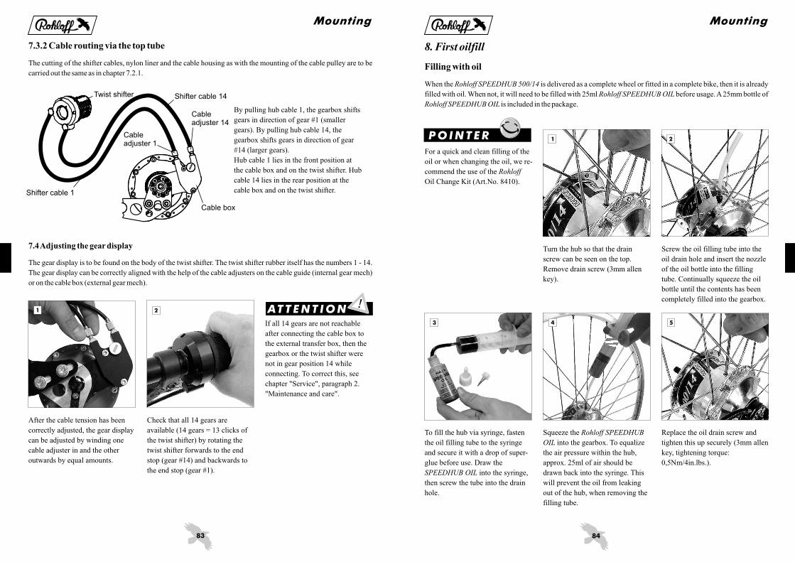
8. First oilfill
Filling with oil
When the is delivered as a complete wheel or fitted in a complete bike, then it is already
filled with oil. When not, it will need to be filled with 25ml before usage.A25mm bottle of
is included in the package.
Rohloff SPEEDHUB 500/14
Rohloff SPEEDHUB OIL
Rohloff SPEEDHUB OIL
Turn the hub so that the drain
screw can be seen on the top.
Remove drain screw (3mm allen
key).
Screw the oil filling tube into the
oil drain hole and insert the nozzle
of the oil bottle into the filling
tube. Continually squeeze the oil
bottle until the contents has been
completely filled into the gearbox.
Squeeze the
into the gearbox. To equalize
the air pressure within the hub,
approx. 25ml of air should be
drawn back into the syringe. This
will prevent the oil from leaking
out of the hub, when removing the
filling tube.
Rohloff SPEEDHUB
OIL
Replace the oil drain screw and
tighten this up securely (3mm allen
key, tightening torque:
0,5Nm/4in.lbs.).
P OI NTE R
To fill the hub via syringe, fasten
the oil filling tube to the syringe
and secure it with a drop of super-
glue before use. Draw the
into the syringe,
then screw the tube into the drain
hole.
SPEEDHUB OIL
For a quick and clean filling of the
oil or when changing the oil, we re-
commend the use of the
Oil Change Kit (Art.No. 8410).
Rohloff
Mounting
85
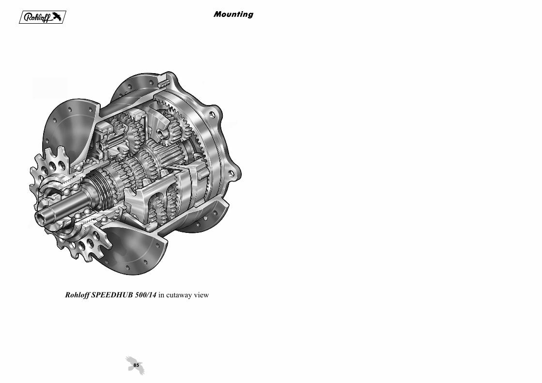
Rohloff SPEEDHUB 500/14 in cutaway view
MountingMounting