SpecBook EN CAN 2011 - Techo Depot · Cubing 13.80 ft2/pal. ( 1.28 m2)/pal. 1.73 ft2/unit ( 0.16...
8
walls Pallet Overview (base) (half) Imperial Metric Cubing 13.80 ft 2 /pal. (1.28 m 2 )/pal. 1.73 ft 2 /unit (0.16 m 2 )/unit Unit A - Weight 287 lb/unit (130 kg)/unit 2,350 lb/pal. (1,065 kg)/pal. Cubing 13.80 ft 2 /pal. (1.28 m 2 )/pal. 3.45 ft 2 /unit (0.32 m 2 )/unit Unit B - Weight 690 lb/unit (312 kg)/unit 2,760 lb/pal. (1,252 kg)/pal. Cubing 6.90 ft 2 /pal. (0.64 m 2 )/pal. 3.45 ft 2 /unit (0.32 m 2 )/unit Unit C - Weight 1,142.50 lb/unit (518 kg)/unit 2,335 lb/pal. (1,059 kg)/pal. Units / pallet in (mm) Unit dimensions A 15.75 (400) 20.50 (521) 15.75 (400) Height Depth Length 8 units B 15.75 (400) 20.50 (521) 31.50 (800) Height Depth Length 4 units C 15.75 (400) 34.50 (876) 31.50 (800) Height Depth Length 2 units HALF REGULAR BASE Compatible caps Only Monumental Blok caps are compatible. Notes Important note: when placing an order for monumental blok, it is important to specify if you are building a vertical or an inclined wall, in order to receive the correct inserts. A , B and C are sold separately. Minimum radius = 17' (5.20 m) For Monumental Blok installation, see p. 115. For more information: 1-800-463-0450 www.techo-bloc.com/monumental (regular) Pallet Overview (see below) Specifications per pallet 08 shale grey A 352108 08 shale grey B 352208 16 mojave beige A 352116 16 mojave beige B 352216 08 shale grey C 352308 16 mojave beige C 352316 TECHO-BLOC WARRANTY H L D Monumental Blok code 3521 (a) 3522 (b) 3523 (c) texture Chiseled 47
Transcript of SpecBook EN CAN 2011 - Techo Depot · Cubing 13.80 ft2/pal. ( 1.28 m2)/pal. 1.73 ft2/unit ( 0.16...

wal
ls
Pallet Overview (base) (half)
Imperial Metric
Cubing 13.80 ft2/pal. (1.28 m2)/pal. 1.73 ft2/unit (0.16 m2)/unit
Unit A - Weight 287 lb/unit (130 kg)/unit 2,350 lb/pal. (1,065 kg)/pal.
Cubing 13.80 ft2/pal. (1.28 m2)/pal. 3.45 ft2/unit (0.32 m2)/unit
Unit B - Weight 690 lb/unit (312 kg)/unit 2,760 lb/pal. (1,252 kg)/pal.
Cubing 6.90 ft2/pal. (0.64 m2)/pal. 3.45 ft2/unit (0.32 m2)/unit
Unit C - Weight 1,142.50 lb/unit (518 kg)/unit 2,335 lb/pal. (1,059 kg)/pal.
Units / pallet in (mm)Unit dimensionsA 15.75 (400)
20.50 (521) 15.75 (400)
Height Depth
Length8 units
B 15.75 (400) 20.50 (521) 31.50 (800)
Height Depth
Length4 units
C 15.75 (400) 34.50 (876) 31.50 (800)
Height Depth
Length2 units
HAL
FRE
GU
LAR
BASE
Compatible capsOnly Monumental Blok caps are compatible.
NotesImportant note: when placing an order for monumental blok, it is important to specify if you are building a vertical or an inclined wall, in order to receive the correct inserts.
A , B and C are sold separately.
Minimum radius = 17' (5.20 m)For Monumental Blok installation, see p. 115.
For more information: 1-800-463-0450www.techo-bloc.com/monumental
(regular)
Pallet Overview(see below)
Specifi cations per pallet
08 shale greyA 3 5 2 1 0 8
08 shale greyB 3 5 2 2 0 8
16 mojave beigeA 3 5 2 1 1 6
16 mojave beigeB 3 5 2 2 1 6
08 shale greyC 3 5 2 3 0 8
16 mojave beigeC 3 5 2 3 1 6
TECHO-BLOCWARRANTYTECHO-BLOCWARRANTY
H
L D
Monumental Blokcode 3521 (a) 3522 (b) 3523 (c)
texture Chiseled
4 7

wal
ls
“Z” insert Lifting Anchor“U” insert
“U” insert creates 10° (23⁄4") inclined wall.
“Z” insert creates straight wall. (vertical)
Imperial Metric
Cubing 20.67 ft2/pal. (1.92 m2)/pal. 5.17 ft2/unit (0.48 m2)/unit
Unit D - Weight 571.25 lb/unit (259 kg)/unit 2,335 lb/pal. (1,059 kg)/pal.
Cubing = 6 rows 29.82 lin. ft/pal. (9.09 lin. m)/pal. 4.97 lin. ft/row (1.51 lin. m)/row
Unit E - Weight 2,705 lb/unit (1,227 kg)/unit
Units / pallet in (mm)Unit dimensionsD 15.75 (400)
15.75 (400) 31.50 (800)
Height Depth
Length4 units
E 3.94 (100) 23 (584) 6.85 (174) 13 (330)
Height Depth
Length 1Length 2
36 units
CORN
ERCA
P
Compatible capsMonumental Blok caps.
Notes* Right or Left corners must be specified
when placing an order.
D and E are sold separately.
For Monumental Blok installation, see p. 115.
For more information: 1-800-463-0450www.techo-bloc.com/monumental
(corner)
Pallet OverviewMonumental Blok cap(see below)
Specifi cations per pallet
08 shale greyD-right 3 5 2 4 0 8D-left 3 5 2 7 0 8
08 shale greyE 3 5 2 5 0 8
16 mojave beigeD-right 3 5 2 4 1 6D-left 3 5 2 7 1 6
16 mojave beigeE 3 5 2 5 1 6
TECHO-BLOCWARRANTYTECHO-BLOCWARRANTY
H
L D
Monumental Blokcode 3524 (left corner) 3527 (right corner) 3525 (cap)texture Chiseled (corners) Split Face (cap)
48

1 1 5
Installation guide for Monumental Blok
tech
nica
lin
form
atio
n
MONUMENTAL BLOK
Segmental retaining wall blocks are enormously popular today, so much that a 24 foot (7 m) high wall supporting a 1000 PSF (48 kPa) load is no longer considered to be a reinforced concrete application. Techo-Bloc’s Monumental Blok is granite-like in appearance and suits high wall applications very well. The base block and regular unit allow versatile applications and offer superior structural strength. The units have tapered sidewalls, allowing interior and exterior curves. When incorporating the built-in 10-degree batter under the right soil conditions, walls as high as 10 feet (3.0 m) can be achieved without the use of geogrid. The appearance of the Monumental Blok will enhance any environment and soften the image of an industrial facility.Monumental Blok requires mechanical installation, greatly reducing installation time and avoiding manual labor. Lifting the Monumental Blok units with excavation equipment already on-site for earthwork reduces crew downtime. With its large profile when placed in a running bond stacking pattern, the Monumental Blok brings back the natural carved beauty of a quarried stone.
MONUMENTAL WALL INSTALLATION INSTRUCTIONS
01 INSPECTION AND PREPARATIONA Plan and execute the project according to the drawings and specifications prepared by the engineer.B Notify the engineer of site conditions which may affect wall performance, soil conditions observed other
than those assumed, or other conditions that may require a reevaluation of the wall design.C Verify the location of existing structures and utilities prior to excavation. D Ensure surrounding structures and buried utilities are protected from the effects of wall excavation. Embankment
support, if required, including stability of the excavation area, are the responsibility of the Contractor.
02 EXCAVATION AND FOUNDATION PREPARATIONA Excavate the native soil to the lines and grades specified on the site grading plans.
After the excavation, the native soil is inspected by an engineer in order to ensure that the soil’s bearing capacity is in keeping with specifications. Use care in excavating to prevent disturbance of the subgrade beyond the lines specified by the engineer.
B Beginning at the lowest elevation point of the Monumental wall, excavate a trench at least 40" (1 m) wide for the regular Monumental Blok unit or 54" (1.35 m) wide for the Monumental Base unit down the length of the wall that will accommodate at least all of the leveling pad and 8" min. (200 mm) of block embedment. Fill over excavated areas with suitable compacted backfill, as recommended by the engineer.
2 B

116
tech
nica
lin
form
atio
nInstallation guide for Monumental Blok
03 LEVELING PAD PREPARATIONA Before laying your leveling pad material, it is recommended that you install a geotextile
membrane along the bottom and banks of the trench to prevent the contamination of soil and leveling pad.
B Place leveling pad material to the depths and widths shown on specifications.C Extend the leveling pad laterally at least 7" (175 mm) in front and 12" (300 mm) behind
the lowermost Monumental retaining wall unit.D The leveling pad should have a minimum thickness of 8" (200 mm) and should be installed
in 6" (150 mm) thick layers and compacted to 95 percent Standard Proctor. The leveling pad should be composed of MG20-type (0-3/4" (0-20 mm)) granular materials.
E Compact granular leveling pad material to provide a level, hard surface on which to place the first course of Monumental Blok units.
F Prepare leveling pad material to ensure complete contact with bottom of all Monumental retaining wall base units installed. Gaps are not tolerated.
04 WALL CONSTRUCTIONA The Monumental Wall unit has a unique lifting system. Techo-Bloc has developed a
driving anchor for lifting and positioning Monumental Blok. Attach a chain or sling (minimal capacity of 2 tons) securely to the Monumental-lifting Anchor provided by Techo-Bloc and insert the Monumental-lifting Anchor into the opening on the top of the block. Turn the Monumental-lifting Anchor 90 degrees to lock the Monumental Blok into place. Lift the Monumental Blok up securely and place into the desired area. Stand clear of the Monumental Blok while it is suspended in the air for safety reasons. (Warning: when lifting the Monumental Blok, ensure that your hands are kept in the designated area of the Monumental-lifting Anchor device at all times to avoid any injury.)
B Select the “U” insert for building a 10˚ batter wall, or the “Z” insert to build a vertical wall. Make sure you notify your local dealer when building a vertical wall, since the “U” insert is standard.
C Place the first course of base block on the prepared leveling pad. Make sure all units are level and aligned correctly. Use a string line measured from the back of the block to set your alignment.
D Place your drainage aggregate in 8" lift and a minimum 12" (300 mm) directly behind, and in the Monumental wall units. Fill in the voids of the Monumental units with drainage aggregate. Cap the backfill and drainage aggregate zone with 8" (200 mm) of impervious material.
E Install a perforated PVC drainage pipe 4" (100 mm) in diameter. Slope the main collection drainage pipe, located just behind the Monumental Blok units (6 mm) per foot (300 mm), this will give you a 2% slope and provide gravity flow to the daylighted areas. You can also connect the drainage pipe to a storm sewer system at 50' (15 m) maximum interval.
Geotextile and compaction
Leveling pad after compaction
Leveling each unit
Installing the first course
1 1 7
tech
nica
lin
form
atio
n
F For inclined (10 degrees) walls, you will use the “U” connector and a “Z” connector for vertical walls. Place the connectors as recommended by the manufacturer. When geogrid is required, the insert must be installed above the geogrid (geosynthetic reinforcement) so that it gets wedged into the slots.
G Check each course for level and alignment. Prior to adding successive courses, the top of each Monumental Blok needs to be cleaned free of foreign material. Note: The Monumental Blok is designed to build a wall vertically or with a 10-degree setback.
H Repeat this process for each successive course. Large compaction or construction equipment should be kept more than 3" (1 meter) away from the back of the wall. This 3-foot area should be compacted with a vibrating plate compactor.
05 MULTI-LEVEL OR STEPPED BASE WALLWhen building a multi-level Monumental wall, each level must be constructed according to rigorous standards.A Separate the elevation into separate landings as per engineer’s specifications and consistent
with the height of Monumental Blok.B When calculating the landing, take into account the drop value of the height
of the Monumental Blok wall.C Step your units accordingly in order to maintain the required embedment.D Maintain running bond joint pattern so that vertical joints are staggered between courses.E Use the Monumental Blok regular to maximize bridging between steps.
06 INSTALLATION OF GEOGRID (IF REQUIRED) Geogrids should be installed according to manufacturers’ recommendations.A Orient the geogrid with the highest strength axis perpendicular to the wall face.B Prior to geogrid placement, place the backfill and compact to the elevation of the top
of the wall units and according to the degree of compacting specified by the engineer. For compacting immediately behind the wall face, see section 4-H.
C Place specified geogrid strength at the specified elevations and to the lengths specified on the wall design.
D Lay the geogrid horizontally on top of the Monumental wall units and the compacted backfill soils. Place the geogrid within two inches of the face of the Monumental wall units. Place the inserts and lay the next course of Monumental wall units on top of the geogrid.
E The geogrid must be pulled taut and free of wrinkles before backfilling your retaining wall. In order to do so, pull the geogrid hand-taut and secure the ends with the placement of staples, stakes, or by hand tensioning your geogrid until it is covered by 6 inches of loose fill.
F The geogrid must be continuous throughout its embedment lengths. Splices in the geogrid strength direction are not tolerated.
07 BACKFILL PLACEMENTA Place backfill at the back of the wall and compact to minimize any geogrid relaxation.B Place fill within the reinforced zone and compact in lifts not exceeding 6" (150 mm) (loose
thickness) where hand-operated compaction equipment is used, and not exceeding 10" (250 mm) (loose thickness) where heavy, self-propelled compaction equipment is used.
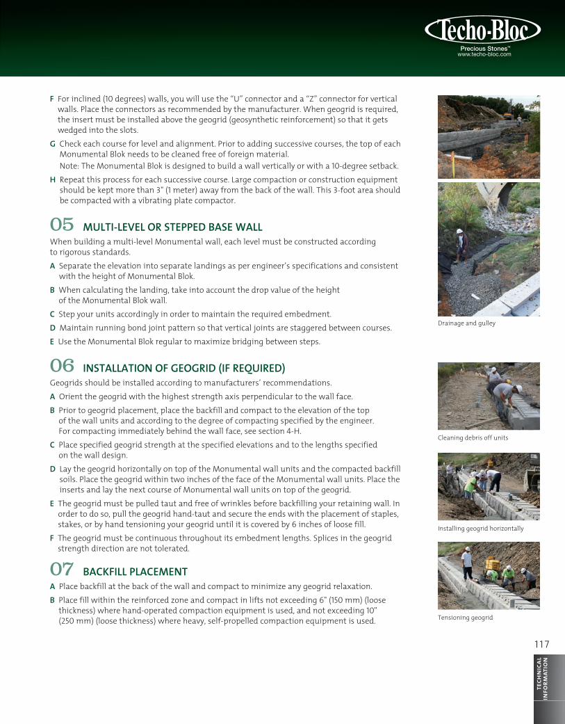
Drainage and gulley
Cleaning debris off units
Installing geogrid horizontally
Tensioning geogrid

118
tech
nica
lin
form
atio
nInstallation guide for Monumental Blok
Note: Only lightweight hand-operated compaction equipment is permitted to operate at less than within 3" (1 meter) of the back of the Monumental wall units. If the specified compaction level cannot be achieved within 3" (1 meter) of the back of the Monumental wall units, replace the reinforced soil in this zone with drainage aggregate material.
C Minimum Compaction Requirements for Fill Placed in the Reinforced ZoneWall Less Than 15’ (4.5 m) High: Compact to 95 percent of the soil’s Standard Proctor maximum dry density (ASTM D698) or amended Proctor (ASTM D1557) for the entire wall height.Walls 15’ (4.5 m) High BUT NOT MORE THAN 30’ (9 m) High: Change compaction requirements to 98 percent of the soil’s Standard Proctor or amended Proctor (ASTM D1557) maximum dry density (ASTM D698) for the entire height up to 30’ (9 m), as indicated by the engineer.Walls Over 30’ (9 m) High: Change compaction requirements to 100 percent of the soil’s Standard Proctor maximum dry density (ASTM D698) or amended Proctor (ASTM D1557) for the entire wall height, as indicated by the engineer.
D Utility Trench Backfill: Compact utility trench backfill in or below the reinforced soil zone to same requirements as the wall height, as indicated by the engineer.Note: Utilities must be properly designed (engineered) to withstand all forces from the Monumental wall units, reinforced soil mass, and surcharge load, if any.
E Moisture Content: Soil shall be moisture conditioned before placement to within 2 percentage points of the optimum moisture content for all wall heights.
F These specifications may be changed based on recommendations by the engineer.G At the end of each day’s operation, slope the last level of compacted backfill to direct surface
water runoff away from the wall face. The General/Earthwork Contractor is responsible for ensuring that the site drainage during construction is directed away from the Monumental wall until permanent site drainage features are operational.
08 CAP UNIT INSTALLATIONA Apply a concrete adhesive to the top of the cleaned surface of the unit below and place
the Monumental cap unit into the desired position.B Cut the Monumental cap units if necessary to obtain the proper fit.C Backfill and compact to top of the Monumental cap unit.
09 CURVE/CORNER INSTALLATIONA CONVEX AND CONCAVE CURVES
Place the Monumental Blok units on the leveling pad such that there are no gaps between the two faces of the Monumental Units used.
When building multiple courses on a curve, begin installation by placing a Monumental Blok in the middle of the curve, centering on two Monumental blocks directly below it. Place the Monumental units side by side from the center block outward along curve.
Place the Monumental caps and measure the distance of the gap between the caps. Using this measurement, cut the Monumental cap so it is parallel with the adjacent Monumental cap unit. Slide the Monumental cap in place so that it is flush with the adjacent Monumental cap unit. The minimal radius obtained with the Monumental Blok is 17' (5.2 m). For each course of block, you need to add 3" (75 mm) onto the final radius. (e.g.: 10 rows or 30" (750 mm) of Monumental Blok will result in a minimal radius at the base of the wall of 19.5' (5.95 m) and will end up with a 17' (5.2 m) radius at the top row of your wall.

1 1 9
tech
nica
lin
form
atio
n
B OUTSIDE 90 DEGREE CORNERWhen building a Monumental wall with an outside 90-degree corner, it is recommended that the construction of the Monumental wall start at the corner desired and work away from this point in both directions.
The placement of the Monumental corner blocks will allow a normal batter consistency in both wall directions.
One standard Monumental corner block will be used at the corner of each course of your wall. The Monumental corner blocks will overlap each other at the corner, coming together in a “zipper fashion”. The Monumental corner blocks should be glued at the corner where they overlap with a concrete adhesive.
C INSIDE 90 DEGREE CORNERWhen building a Monumental wall with an inside 90-degree corner, it is recommended that you start each subsequent course at the corner and lay out block from that corner. Repeat Step B on building an outside 90-degree corner.
D FENCING/GUARD RAILSGuard rails and handrails should be installed behind the Monumental Blok in the soil. It is possible to install a fencing at the top of the Monumental wall by core drilling into the top of the Monumental Blok. Follow the instructions of the railing manufacturer and wall design engineer. It is, however, recommended that if the fencing is to be installed at the top of the wall, glue the top two rows of Monumental Blok to the rows of Monumental Blok beneath it with a concrete adhesive.

tech
nica
lin
form
atio
nInstallation guidefor Monumental Blok
10 GEOGRID INSTALLATION IN A CURVE/CORNER APPLICATION
A CONVEX CURVE1. Place geogrid perpendicular to wall face at center of geogrid. Trim your geogrid
(geosynthetic reinforcement) to fit onto the curved face of the wall and place your geogrid with the curve to follow its contour.
2. Overlapping layers of geogrid on a convex curve requires a minimum of 3" (75 mm) of soil between them for proper anchoring. Repeat for successive specified geogrid layers.
3. Place the geogrid to the length specified by the wall designer.
B CONCAVE CURVE1. The strength direction of the geogrid (geosynthetic reinforcement) must be placed
perpendicular to the wall face; align the cut geogrid sections so that it follows the contour of the concave curve. Geogrid layers should not overlap. The desired length of geogrid should be specified by a wall designer.
2. The next successive geogrid layer must be placed to cover the area of reinforced soil below. This will maximize lapping. Repeat these steps for successive specified geogrid layers.
C OUTSIDE 90 DEGREE CORNEROn an outside 90-degree corner it is important that the geogrid (geosynthetic reinforcement) layers that overlap are covered by 3" (75 mm) of soil at the overlap for proper anchorage. Repeat for successive specified geogrid layers.
11 FINAL TOUCHWhen prelaying the last course of Monumental Blok and capstones, overlap the geotextile towards the wall totally covering the 3⁄4" (20 mm) clear crushed stone (drainage material). Use impervious soil to cover the drainage stone and remainder of the back fill. The soil cap must be manually compacted and it is recommended that a swale be created in order to channel water off the top of the wall. For all other applications such as concrete or asphalt situated behind the wall, it is a requirement that you compact the 2' (0.6 m) behind the Monumental wall with a lightweight compacting plate at 6" (15 cm) intervals.
12 NOTESThese installation guidelines provided by Techo-Bloc are consistent with industry standards in general and NCMA design methodology and guidelines. Global stability of the wall being built should be addressed by the site designer or project geotechnical engineer. The correct application of any design is the responsibility of the user and should be verified by an engineer. A local wall designer should engineer all retaining walls for site specific conditions.For safety during construction a safety rail or net must be installed securely onto your Monumental wall for the fall protection of the wall installers.When building a Monumental wall over five feet all persons working around the perimeter of the wall must be securely harnessed. It should be noted that all suggestions and recommendations by Techo-Bloc are based on general industry instructions, and should not be interpreted as constituting an engineer’s specifications.
120

![Unit 1 Where’s your pen pal from?. Where’s your pen pal from? [pæl ]](https://static.fdocuments.in/doc/165x107/56649dd95503460f94acec0b/unit-1-wheres-your-pen-pal-from-wheres-your-pen-pal-from-pael-.jpg)