soviet intensive economic development in perspective ( sov86-10006)
SIGMA Production Ducoment 10006 – FM KHUSAT-03 Vibration Testing
Page 1/41
SPD 10006 – FM KHUSAT-03
Vibration Testing
Document Author(s):
Jehyuck Shin [email protected]
Responsible Engineer(s):
Seongwhan Lee [email protected]
Jungho Lee [email protected]
SIGMA Production Ducoment 10006 – FM KHUSAT-03 Vibration Testing
Page 2/41
Revision History
Revision Description Author Date
00 Draft Document Jehyuck Shin 11/20/15
01 Revision Update Seongwhan Lee 11/20/15
02 Revision Update Jehyuck Shin 11/24/15
2.5 Revision Update Jehyuck Shin 11/26/15
3.0 Revision Update Seongwhan Lee 11/26/15
3.1 Revision Update Jehyuck Shin 11/26/15
3.2 TEPC Additional Test Seongwhan Lee 01/27/16
SIGMA Production Ducoment 10006 – FM KHUSAT-03 Vibration Testing
Page 3/41
List of Abbreviations and Acronyms
SIGMA – Scientific cubesat with Instruments for Global Magnetic field and rAdiation KHUSAT – Kyung Hee University SATellite KHU – Kyung Hee Univeristy SSR – School of Space Research YU – York University, Canada UNH – University of New Hampshire, USA VT – Virginia Tech, USA TestPOD - Test Picosatellite Orbital Deployer P-POD – Poly-Picosatellite Orbital Deployer UUT – Unit Under Test TEPC – Tissue Equivalent Proportional Counter MAG – miniaturized fluxgate MAGnetometer IIB – Instrument Interface Board OBC – On Board Computer RBF – Remove Before Flight P/N – Part Number QM – Qualifying Model FM – Flight Model BRF – Body Reference Frame LRF – Launcher Reference Frame PRS – PRe Sine sweep vibration test RV – Random Vibration test POS – POst Sine sweep vibration test CMD – CoMmanD N/A - Not Applicable P - Pass F - Fail NF – Natural Frequency FRF – Frequency Response Function
SIGMA Production Ducoment 10006 – FM KHUSAT-03 Vibration Testing
Page 4/41
Special Notes
CAUTION
Note: CAUTION notes identify situations where flight hardware may be damaged without proper attention.
DANGER
Note: DANGER notes identify situations where bodily harm may occur without proper attention.
SIGMA Production Ducoment 10006 – FM KHUSAT-03 Vibration Testing
Page 5/41
Table of Contents
1. Introduction ................................................................................................................................................................. 7
1.1 Characteristics of SIGMA .............................................................................................................................. 7
2. Equipment for the vibration test................................................................................................................................ 7
2.1. Shaker .................................................................................................................................................................. 7
2.2. Accelerometer .................................................................................................................................................... 9
3. Test procedure ........................................................................................................................................................... 10
3.1. Test requirement ............................................................................................................................................. 12
3.1.1 Sine sweep vibration test characteristics .................................................................................. 12
3.1.2 Random vibration test characteristics ....................................................................................... 12
3.2 Accelerometer points ...................................................................................................................................... 13
4. Vibration test ............................................................................................................................................................. 16
4.1 Issues of vibration test ................................................................................................................................... 16
4.2 X axis of SIGMA .............................................................................................................................................. 17
4.2.1 Response data ..................................................................................................................................... 17
4.2.2 Result ..................................................................................................................................................... 20
4.3 Y axis of SIGMA .............................................................................................................................................. 21
4.3.1 Response data ..................................................................................................................................... 21
4.3.2 Result ..................................................................................................................................................... 24
4.4 Z axis of SIGMA .............................................................................................................................................. 25
4.4.1 Response data ..................................................................................................................................... 25
4.4.2 Result ..................................................................................................................................................... 28
SIGMA Production Ducoment 10006 – FM KHUSAT-03 Vibration Testing
Page 6/41
5. Pass/Fail criteria ....................................................................................................................................................... 29
6. Appendix A ................................................................................................................................................................ 32
6.1 Mechanical problem of TEPC (Korean) .................................................................................................. 32
SIGMA Production Ducoment 10006 – FM KHUSAT-03 Vibration Testing
Page 7/41
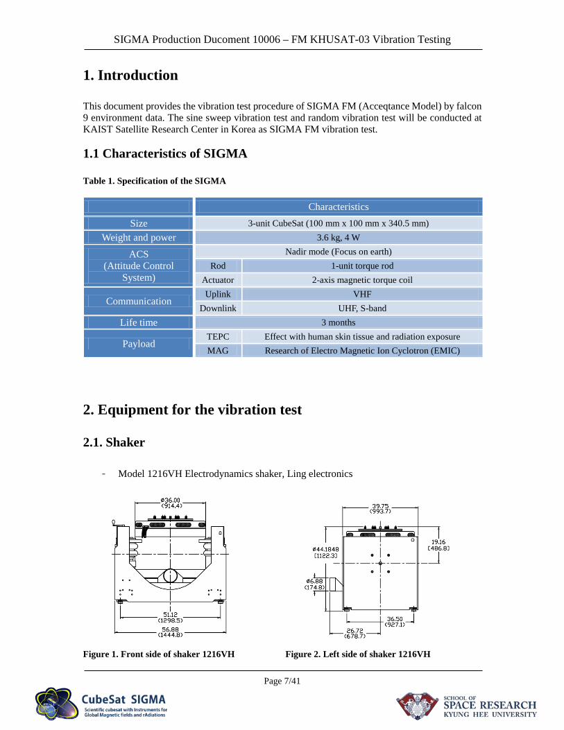
1. Introduction
This document provides the vibration test procedure of SIGMA FM (Acceqtance Model) by falcon 9 environment data. The sine sweep vibration test and random vibration test will be conducted at KAIST Satellite Research Center in Korea as SIGMA FM vibration test. 1.1 Characteristics of SIGMA
Table 1. Specification of the SIGMA
Characteristics
Size 3-unit CubeSat (100 mm x 100 mm x 340.5 mm) Weight and power 3.6 kg, 4 W
ACS (Attitude Control
System)
Nadir mode (Focus on earth) Rod 1-unit torque rod
Actuator 2-axis magnetic torque coil
Communication Uplink VHF
Downlink UHF, S-band Life time 3 months
Payload TEPC Effect with human skin tissue and radiation exposure MAG Research of Electro Magnetic Ion Cyclotron (EMIC)
2. Equipment for the vibration test
2.1. Shaker
- Model 1216VH Electrodynamics shaker, Ling electronics
Figure 1. Front side of shaker 1216VH Figure 2. Left side of shaker 1216VH
SIGMA Production Ducoment 10006 – FM KHUSAT-03 Vibration Testing
Page 8/41
Table 2. Specification of shaker 1216VH
Axial stiffness 77 kN/m
Armature diameter 438 mm
Armature mass 54.43 kg
Armature suspension Half-loop metallic flexures
Static load support 454 kg
Maximum velocity 1.78 m/s
Frequency range 4 to 3000 Hz Maximum
acceleration 100 g sine vector
Utility power 123 kVA
Force rating 53.4 peak sine
53.4 rms random 106.8 kN Shock
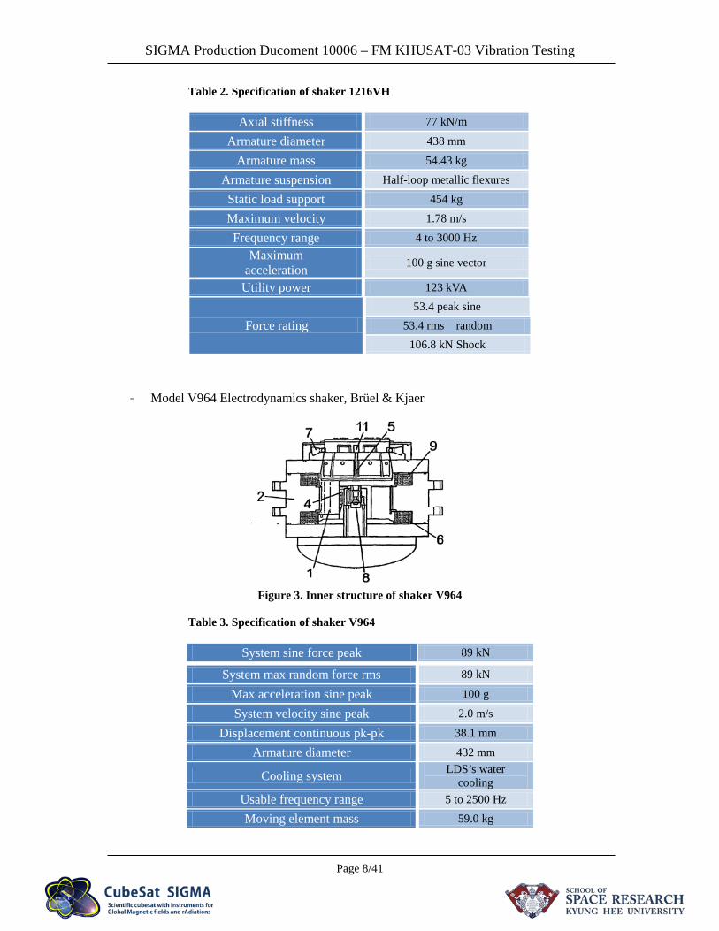
- Model V964 Electrodynamics shaker, Brüel & Kjaer
Figure 3. Inner structure of shaker V964
Table 3. Specification of shaker V964
System sine force peak 89 kN
System max random force rms 89 kN
Max acceleration sine peak 100 g
System velocity sine peak 2.0 m/s
Displacement continuous pk-pk 38.1 mm
Armature diameter 432 mm
Cooling system LDS’s water cooling
Usable frequency range 5 to 2500 Hz
Moving element mass 59.0 kg
SIGMA Production Ducoment 10006 – FM KHUSAT-03 Vibration Testing
Page 9/41
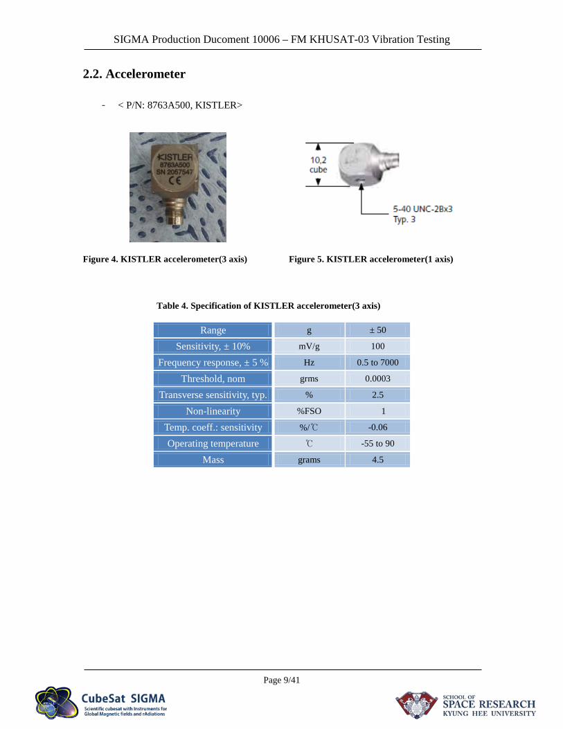
2.2. Accelerometer
- < P/N: 8763A500, KISTLER>
Figure 4. KISTLER accelerometer(3 axis) Figure 5. KISTLER accelerometer(1 axis)
Table 4. Specification of KISTLER accelerometer(3 axis)
Range g ± 50
Sensitivity, ± 10% mV/g 100
Frequency response, ± 5 % Hz 0.5 to 7000
Threshold, nom grms 0.0003
Transverse sensitivity, typ. % 2.5
Non-linearity %FSO ± 1
Temp. coeff.: sensitivity %/℃ -0.06
Operating temperature ℃ -55 to 90
Mass grams 4.5
SIGMA Production Ducoment 10006 – FM KHUSAT-03 Vibration Testing
Page 10/41
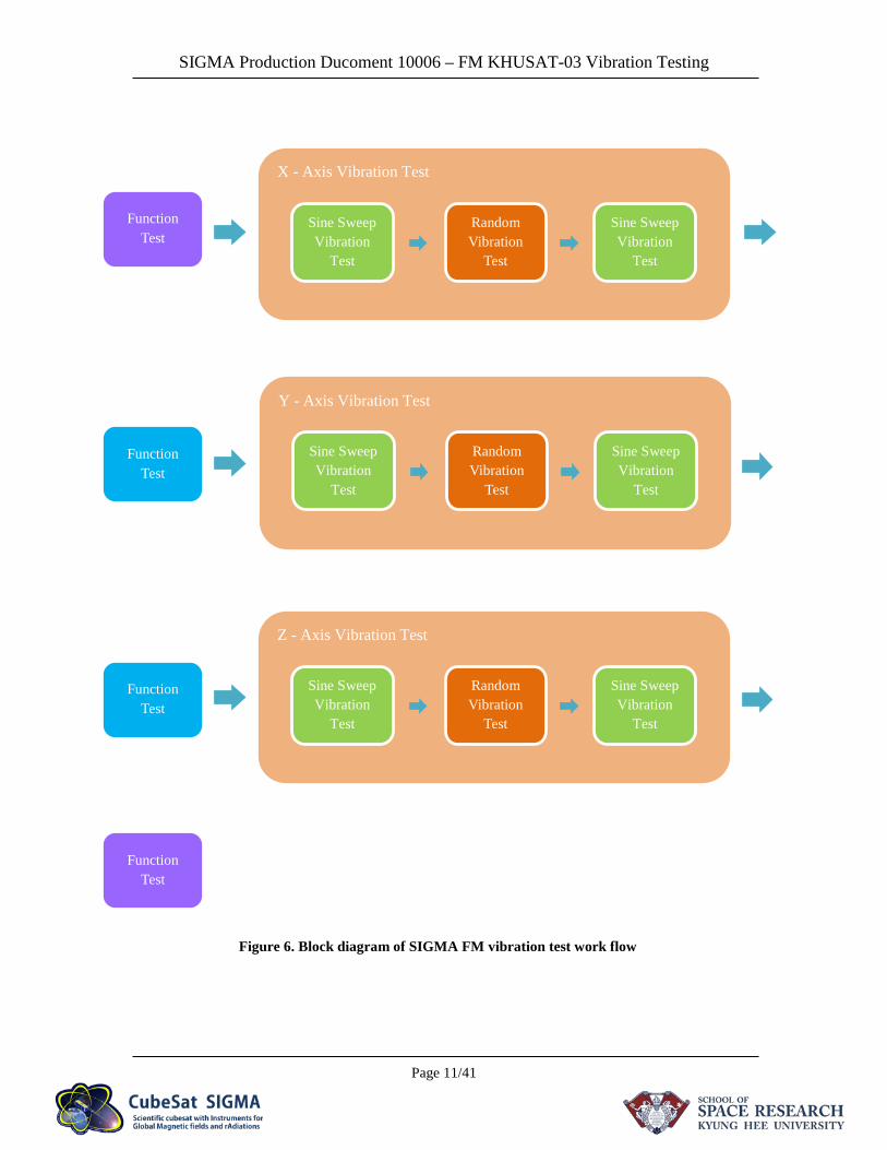
3. Test procedure
Prior to arrival at the test facility shakedown test will be conducted using mass dummy (1 to 2kg) in order to validate the acceptance level random noise. This shall be conducted in lateral directions.
The test sequence for each of the three orthogonal axes is normally as follows: I. Spacecraft functional checkout II. Qualification random noise III. Spacecraft functional checkout
Note: The test pod should not exhibit significant resonant frequencies below 2000Hz. The order in which the axis tests are carried out may vary due to the initial configuration of the shaker. Accelerometer readings will be inspected after each test in order to identify possible anomalies. Visual Inspection of the FM spacecraft shall be performed after the test sequence.
Table 5. Work flow of SIGMA FM vibration test
Run # Test Description Comments
Run 1 Function Test Spacecraft functional checkout
Run 2 X_axis vibration test Sine sweep vibration test → Random vibration test →
Sine sweep vibration test
Run 3 Function Test Check by Eye and check the CMD
Run 4 Y_ axis vibration test Sine sweep vibration test → Random vibration test →
Sine sweep vibration test
Run 5 Function Test Check by Eye and check the CMD
Run 6 Z_ axis vibration test Sine sweep vibration test → Random vibration test →
Sine sweep vibration test
Run 7 Function Test Spacecraft functional checkout
SIGMA Production Ducoment 10006 – FM KHUSAT-03 Vibration Testing
Page 11/41
X - Axis Vibration Test
Random Vibration
Test
Sine Sweep Vibration
Test
Sine Sweep Vibration
Test
Function Test
Function Test
Function Test
Function Test
Y - Axis Vibration Test
Random Vibration
Test
Sine Sweep Vibration
Test
Sine Sweep Vibration
Test
Z - Axis Vibration Test
Random Vibration
Test
Sine Sweep Vibration
Test
Sine Sweep Vibration
Test
Figure 6. Block diagram of SIGMA FM vibration test work flow
SIGMA Production Ducoment 10006 – FM KHUSAT-03 Vibration Testing
Page 12/41
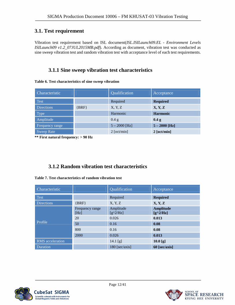
3.1. Test requirement
Vibration test requirement based on ISL document(ISL.ISILaunch09.EL - Environment Levels ISILaunch09 v1.2_07JUL2015MB.pdf). According as document, vibration test was conducted as sine sweep vibration test and random vibration test with acceptance level of each test requirements.
3.1.1 Sine sweep vibration test characteristics
Table 6. Test characteristics of sine sweep vibration
Characteristic Qualification Acceptance
Test Required Required Directions {BRF} X, Y, Z X, Y, Z Type Harmonic Harmonic Amplitude 0.4 g 0.4 g Frequency range 5 – 2000 [Hz] 5 – 2000 [Hz] Sweep Rate 2 [oct/min] 2 [oct/min]
** First natural frequency: > 90 Hz
3.1.2 Random vibration test characteristics
Table 7. Test characteristics of random vibration test
Characteristic Qualification Acceptance
Test Required Required Directions {BRF} X, Y, Z X, Y, Z
Profile
Frequency range [Hz]
Amplitude [g^2/Hz]
Amplitude [g^2/Hz]
20 0.026 0.013 50 0.16 0.08 800 0.16 0.08 2000 0.026 0.013
RMS acceleration 14.1 [g] 10.0 [g] Duration 180 [sec/axis] 60 [sec/axis]
SIGMA Production Ducoment 10006 – FM KHUSAT-03 Vibration Testing
Page 13/41
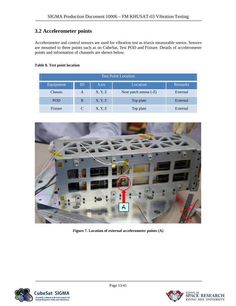
3.2 Accelerometer points
Accelerometer and control sensors are used for vibration test as triaxis measurable snesor. Sensors are mounted to three points such as on CubeSat, Test POD and Fixture. Details of accelerometer points and information of channels are shown below. Table 8. Test point location
Figure 7. Location of external accelerometer points (A)
Test Point Location
Equipment ID Axis Location Remarks
Chassis A X, Y, Z Near patch antena (-Z) External
POD B X, Y, Z Top plate External
Fixture C X, Y, Z Top plate External
SIGMA Production Ducoment 10006 – FM KHUSAT-03 Vibration Testing
Page 14/41
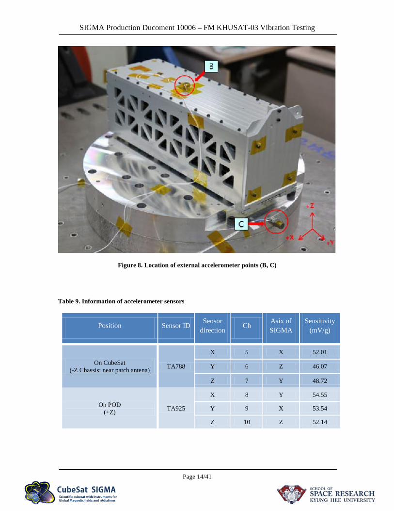
Figure 8. Location of external accelerometer points (B, C)
Table 9. Information of accelerometer sensors
Position Sensor ID Seosor direction
Ch Asix of SIGMA
Sensitivity (mV/g)
On CubeSat (-Z Chassis: near patch antena) TA788
X 5 X 52.01
Y 6 Z 46.07
Z 7 Y 48.72
On POD (+Z) TA925
X 8 Y 54.55
Y 9 X 53.54
Z 10 Z 52.14
SIGMA Production Ducoment 10006 – FM KHUSAT-03 Vibration Testing
Page 15/41
Table 10. Information of control sensors
Control Sensor ID Ch Asix of
SIGMA Sensitivity
(mV/g) Remark
Lateral control (fixture) S1004 1 Lateral
(X, Y) 101.5 Ch 1 of S1004 was replaced to Ch 11 at POS of Y axis.
Vertical Control (fixture) SA458 11 Vertical
(Z) 104.1
Table 11. Channel information of each axis
Body Reference Frame Measurement channel information
X axis Ch5, Ch9
Y axis Ch7, Ch8
Z axis Ch6, Ch10
SIGMA Production Ducoment 10006 – FM KHUSAT-03 Vibration Testing
Page 16/41
4. Vibration test
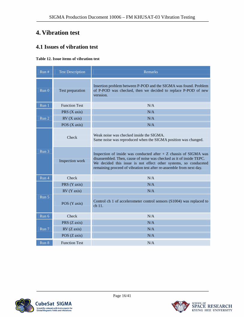
4.1 Issues of vibration test
Table 12. Issue items of vibration test
Run # Test Description Remarks
Run 0 Test preparation
Insertion problem between P-POD and the SIGMA was found. Problem of P-POD was checked, then we decided to replace P-POD of new verssion.
Run 1 Function Test N/A
Run 2 PRS (X axis) N/A RV (X axis) N/A
POS (X axis) N/A
Run 3
Check
Weak noise was checked inside the SIGMA. Same noise was reproduced when the SIGMA position was changed.
Inspection work
Inspection of inside was conducted after + Z chassis of SIGMA was disassembled. Then, cause of noise was checked as it of inside TEPC. We decided this issue is not effect other systems, so conduceted remaining proceed of vibration test after re-assemble from next day.
Run 4 Check N/A
Run 5
PRS (Y axis) N/A RV (Y axis) N/A
POS (Y axis)
Control ch 1 of accelerometer control sensors (S1004) was replaced to ch 11.
Run 6 Check N/A
Run 7 PRS (Z axis) N/A RV (Z axis) N/A
POS (Z axis) N/A
Run 8 Function Test N/A
SIGMA Production Ducoment 10006 – FM KHUSAT-03 Vibration Testing
Page 17/41
4.2 X axis of SIGMA
Table 13. Channel informations of accelerometer sensors (X axis)
Sensor Position Asix of SIGMA Ch
Accelerometer sensors Chassis (-Z) X 5
Top on POD X 9
Control sensor On fixture X, Y (Lateral) 1
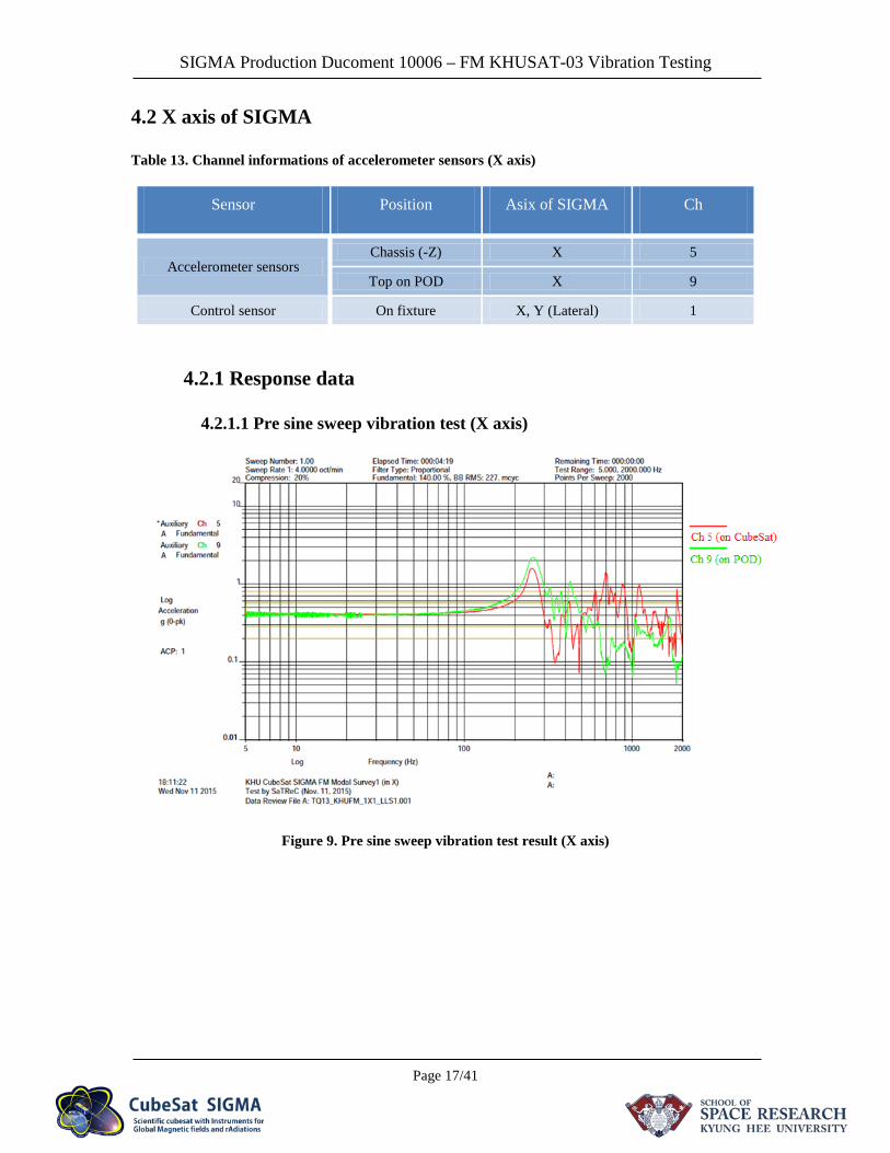
4.2.1 Response data
4.2.1.1 Pre sine sweep vibration test (X axis)
Figure 9. Pre sine sweep vibration test result (X axis)
SIGMA Production Ducoment 10006 – FM KHUSAT-03 Vibration Testing
Page 18/41
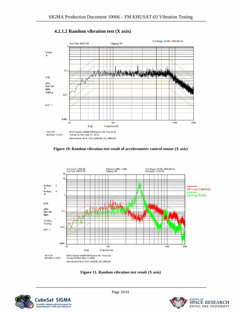
4.2.1.2 Random vibration test (X axis)
Figure 10. Random vibration test result of accelerometer control sensor (X axis)
Figure 11. Random vibration test result (X axis)
SIGMA Production Ducoment 10006 – FM KHUSAT-03 Vibration Testing
Page 19/41
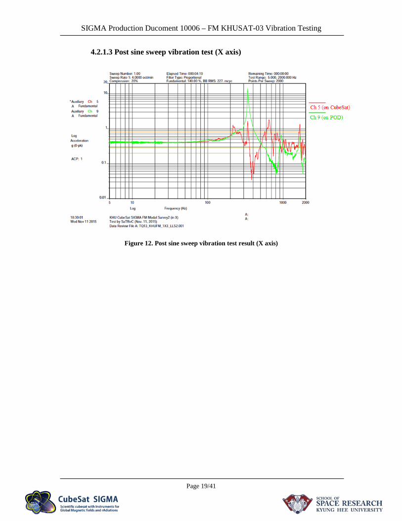
4.2.1.3 Post sine sweep vibration test (X axis)
Figure 12. Post sine sweep vibration test result (X axis)
SIGMA Production Ducoment 10006 – FM KHUSAT-03 Vibration Testing
Page 20/41
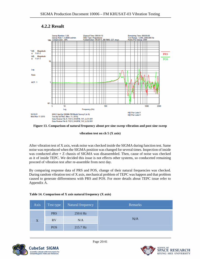
4.2.2 Result
Figure 13. Comparison of natural frequency about pre sine sweep vibration and post sine sweep
vibration test on ch 5 (X axis)
After vibration test of X axis, weak noise was checked inside the SIGMA during function test. Same noise was reproduced when the SIGMA position was changed for several times. Inspection of inside was conducted after + Z chassis of SIGMA was disassembled. Then, cause of noise was checked as it of inside TEPC. We decided this issue is not effects other systems, so conduceted remaining proceed of vibration test after re-assemble from next day. By comparing response data of PRS and POS, change of their natural frequencies was checked. During random vibration test of X axis, mechanical problem of TEPC was happen and that problem caused to generate differentness with PRS and POS. For more details about TEPC issue refer to Appendix A.
Table 14. Comparison of X axis natural frequency (X axis)
Axis Test type Natural frequency Remarks
X
PRS 250.6 Hz
N/A RV N/A
POS 215.7 Hz
SIGMA Production Ducoment 10006 – FM KHUSAT-03 Vibration Testing
Page 21/41
4.3 Y axis of SIGMA
Table 15. Channel informations of accelerometer sensors (Y axis)
Sensor Position Asix of SIGMA Ch
Accelerometer sensors Chassis (-Z) Y 7
Top on POD Y 8
Control sensor On fixture X, Y (Lateral) 1 → 11
* Ch 1 of lateral control sensor was replaced to Ch 11 at POS of Y axis due to data acquisition problem of ch 1.
4.3.1 Response data
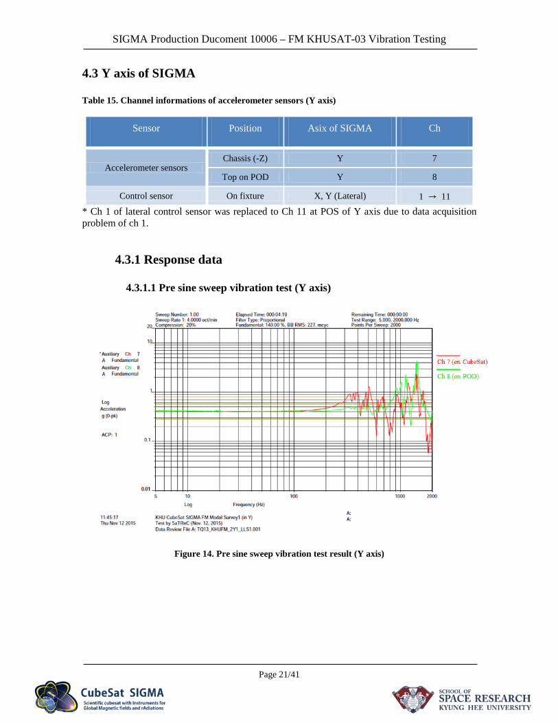
4.3.1.1 Pre sine sweep vibration test (Y axis)
Figure 14. Pre sine sweep vibration test result (Y axis)
SIGMA Production Ducoment 10006 – FM KHUSAT-03 Vibration Testing
Page 22/41
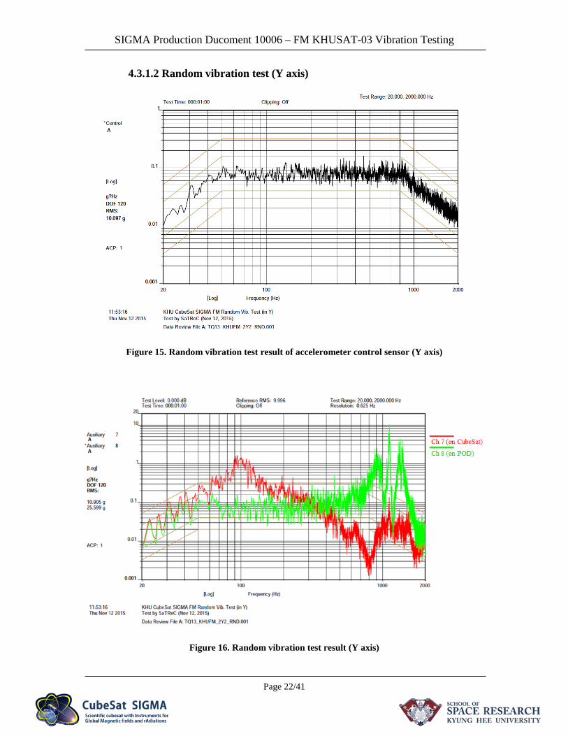
4.3.1.2 Random vibration test (Y axis)
Figure 15. Random vibration test result of accelerometer control sensor (Y axis)
Figure 16. Random vibration test result (Y axis)

SIGMA Production Ducoment 10006 – FM KHUSAT-03 Vibration Testing
Page 23/41
4.3.1.3 Post sine sweep vibration test_1 (Y axis)
Figure 17. Post sine sweep vibration test result (Y axis)
SIGMA Production Ducoment 10006 – FM KHUSAT-03 Vibration Testing
Page 24/41
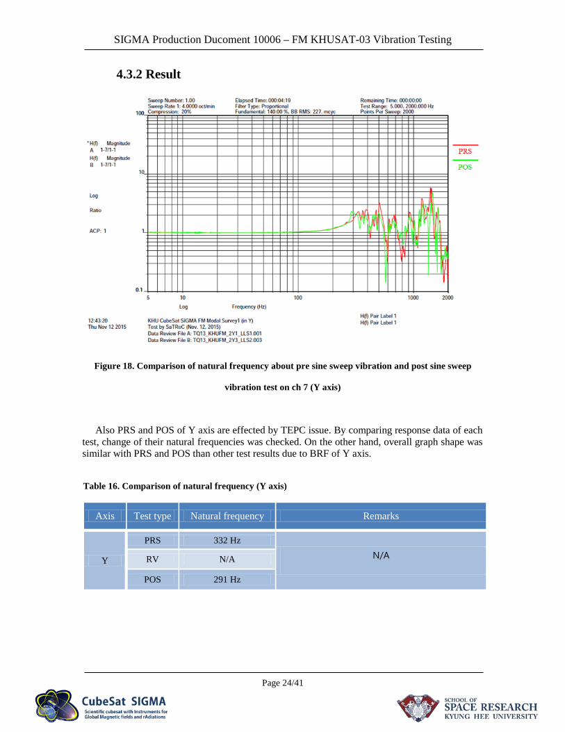
4.3.2 Result
Figure 18. Comparison of natural frequency about pre sine sweep vibration and post sine sweep
vibration test on ch 7 (Y axis)
Also PRS and POS of Y axis are effected by TEPC issue. By comparing response data of each test, change of their natural frequencies was checked. On the other hand, overall graph shape was similar with PRS and POS than other test results due to BRF of Y axis.
Table 16. Comparison of natural frequency (Y axis)
Axis Test type Natural frequency Remarks
Y
PRS 332 Hz
N/A RV N/A
POS 291 Hz
SIGMA Production Ducoment 10006 – FM KHUSAT-03 Vibration Testing
Page 25/41
4.4 Z axis of SIGMA
Table 17. Channel informations of accelerometer sensors (Z axis)
Sensor Position Asix of SIGMA Ch
Accelerometer sensors Chassis (-Z) Z 6
Top on POD Z 10
Control sensor On fixture Z (Vertical) 11
4.4.1 Response data
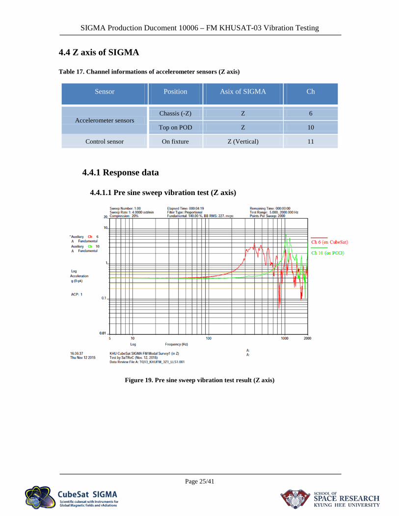
4.4.1.1 Pre sine sweep vibration test (Z axis)
Figure 19. Pre sine sweep vibration test result (Z axis)
SIGMA Production Ducoment 10006 – FM KHUSAT-03 Vibration Testing
Page 26/41
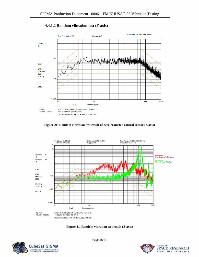
4.4.1.2 Random vibration test (Z axis)
Figure 20. Random vibration test result of accelerometer control sensor (Z axis)
Figure 21. Random vibration test result (Z axis)
SIGMA Production Ducoment 10006 – FM KHUSAT-03 Vibration Testing
Page 27/41
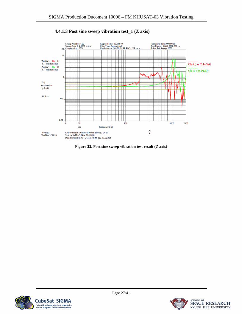
4.4.1.3 Post sine sweep vibration test_1 (Z axis)
Figure 22. Post sine sweep vibration test result (Z axis)
SIGMA Production Ducoment 10006 – FM KHUSAT-03 Vibration Testing
Page 28/41
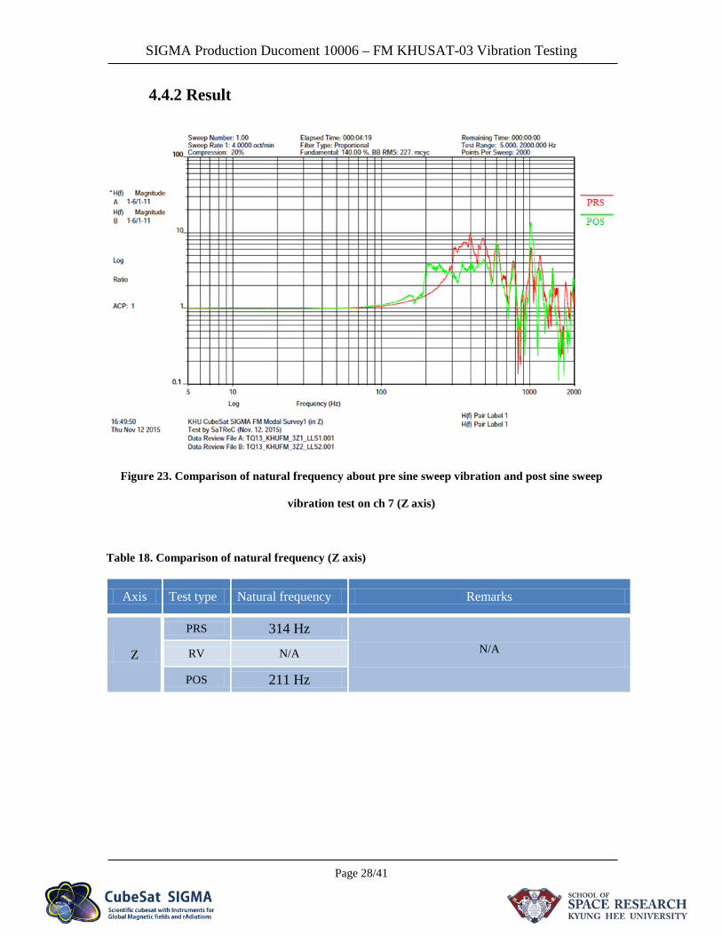
4.4.2 Result
Figure 23. Comparison of natural frequency about pre sine sweep vibration and post sine sweep
vibration test on ch 7 (Z axis)
Table 18. Comparison of natural frequency (Z axis)
Axis Test type Natural frequency Remarks
Z
PRS 314 Hz N/A RV N/A
POS 211 Hz
SIGMA Production Ducoment 10006 – FM KHUSAT-03 Vibration Testing
Page 29/41
5. Pass/Fail criteria
A successful test is defined by a component not being at all affected by the vibrations test. This is measured by visual inspection, as well as performing a physical and/or electrical inspection before and after the vibration test. This ensures that the component was working before testing began, and continued to work after testing was completed. Even if the component passes the physical/electrical test after the vibration test, any noticeable changes made to the component during the vibration test will be enough to fail the component. UUT has successfully passed vibration testing if the unit is not degraded mechanically, functionally, or structurally. Success criteria shall consist of: Verification will consist of visual inspections, inspection of accelerometer output data, and acceptable functional deployment. Note: It is not possible to codify a completely comprehensive PASS/FAIL Criteria for this type of Vibration Data. Test Conductor along with SSR/KHU Mechanical Engineer shall evaluate all test data.
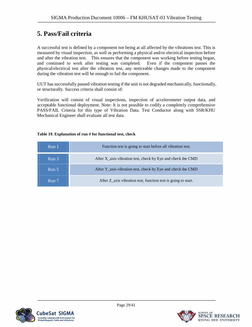
Table 19. Explanation of run # for functional test, check
Run 1 Function test is going to start before all vibration test.
Run 3 After X_axis vibration test, check by Eye and check the CMD
Run 5 After Y_axis vibration test, check by Eye and check the CMD
Run 7 After Z_axis vibration test, function test is going to start.
SIGMA Production Ducoment 10006 – FM KHUSAT-03 Vibration Testing
Page 30/41
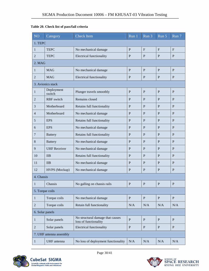
Table 20. Check list of pass/fail criteria
NO Category Check Item Run 1 Run 3 Run 5 Run 7
1. TEPC
1 TEPC No mechanical damage P F F F
2 TEPC Electrical functionality P P P P
2. MAG
1 MAG No mechanical damage P P P P
2 MAG Electrical functionality P P P P
3. Avionics stack
1 Deployment switch Plunger travels smoothly P P P P
2 RBF switch Remains closed P P P P
3 Motherboard Retains full functionality P P P P
4 Motherboard No mechanical damage P P P P
5 EPS Retains full functionality P P P P
6 EPS No mechanical damage P P P P
7 Battery Retains full functionality P P P P
8 Battery No mechanical damage P P P P
9 UHF Receiver No mechanical damage P P P P
10 IIB Retains full functionality P P P P
11 IIB No mechanical damage P P P P
12 HVPS (Mockup) No mechanical damage P P P P
4. Chassis
1 Chassis No galling on chassis rails P P P P
5. Torque coils
1 Torque coils No mechanical damage P P P P
2 Torque coils Retain full functionality N/A N/A N/A N/A
6. Solar panels
1 Solar panels No structural damage that causes loss of functionality P P P P
2 Solar panels Electrical functionality P P P P
7. UHF antenna assembly
1 UHF antenna No loss of deployment functionality N/A N/A N/A N/A
SIGMA Production Ducoment 10006 – FM KHUSAT-03 Vibration Testing
Page 31/41
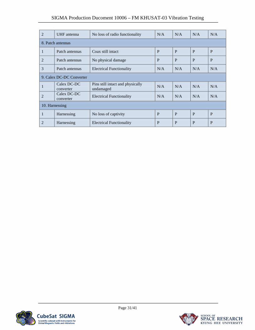
2 UHF antenna No loss of radio functionality N/A N/A N/A N/A
8. Patch antennas
1 Patch antennas Coax still intact P P P P
2 Patch antennas No physical damage P P P P
3 Patch antennas Electrical Functionality N/A N/A N/A N/A
9. Calex DC-DC Converter
1 Calex DC-DC converter
Pins still intact and physically undamaged N/A N/A N/A N/A
2 Calex DC-DC converter Electrical Functionality N/A N/A N/A N/A
10. Harnessing
1 Harnessing No loss of captivity P P P P
2 Harnessing Electrical Functionality P P P P
SIGMA Production Ducoment 10006 – FM KHUSAT-03 Vibration Testing
Page 32/41
6. Appendix A
6.1 Mechanical problem of TEPC (Korean)
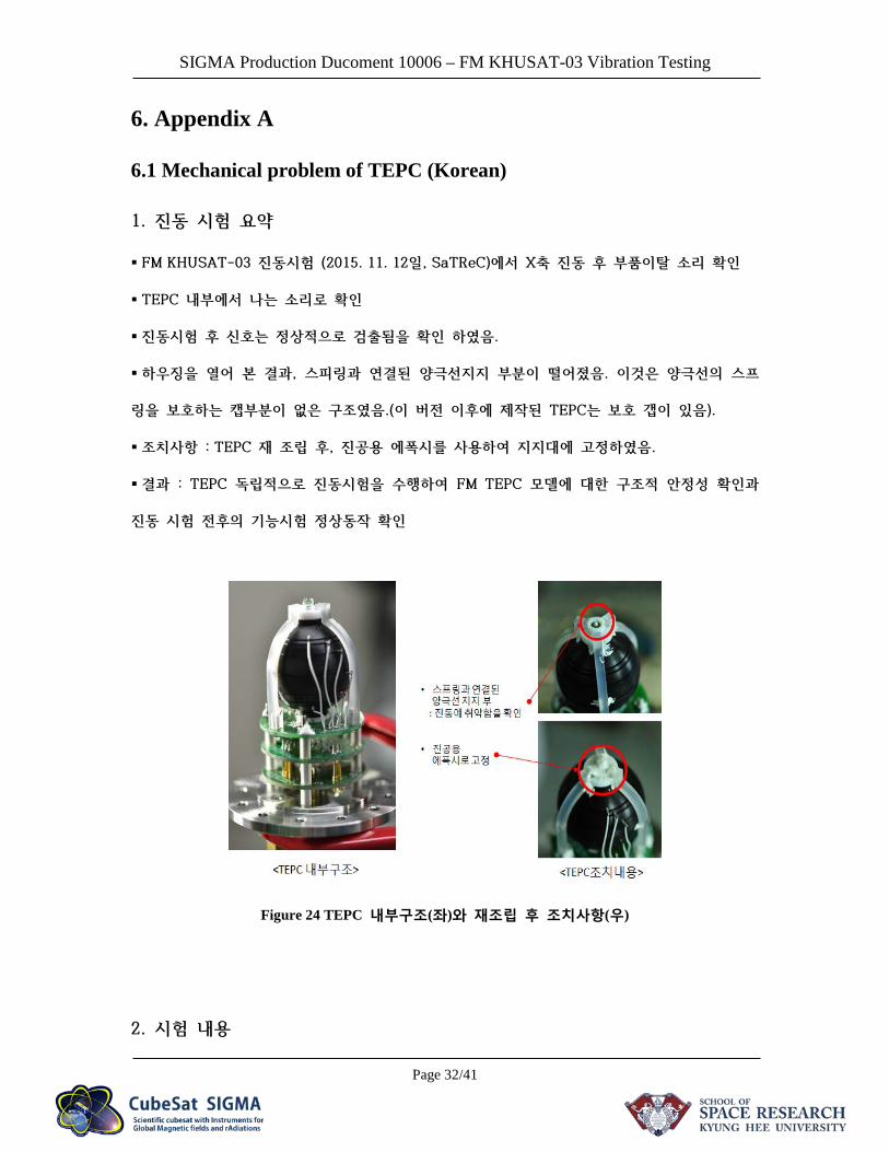
1. 진동 시험 요약
FM KHUSAT-03 진동시험 (2015. 11. 12일, SaTReC)에서 X축 진동 후 부품이탈 소리 확인
TEPC 내부에서 나는 소리로 확인
진동시험 후 신호는 정상적으로 검출됨을 확인 하였음.
하우징을 열어 본 결과, 스피링과 연결된 양극선지지 부분이 떨어졌음. 이것은 양극선의 스프
링을 보호하는 캡부분이 없은 구조였음.(이 버전 이후에 제작된 TEPC는 보호 갭이 있음).
조치사항 : TEPC 재 조립 후, 진공용 에폭시를 사용하여 지지대에 고정하였음.
결과 : TEPC 독립적으로 진동시험을 수행하여 FM TEPC 모델에 대한 구조적 안정성 확인과
진동 시험 전후의 기능시험 정상동작 확인
Figure 24 TEPC 내부구조(좌)와 재조립 후 조치사항(우)
2. 시험 내용
SIGMA Production Ducoment 10006 – FM KHUSAT-03 Vibration Testing
Page 33/41
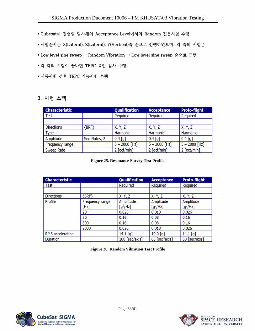
Cubesat이 경험할 발사체의 Acceptance Level에서의 Random 진동시험 수행
시험순서는 X(Lateral), Z(Lateral), Y(Vertical)축 순으로 진행하였으며, 각 축의 시험은
Low level sine sweep ⟶ Random Vibration ⟶ Low level sine sweep 순으로 진행
각 축의 시험이 끝나면 TEPC 육안 검사 수행
진동시험 전후 TEPC 기능시험 수행
3. 시험 스펙
Figure 25. Resonance Survey Test Profile
Figure 26. Random Vibration Test Profile
SIGMA Production Ducoment 10006 – FM KHUSAT-03 Vibration Testing
Page 34/41
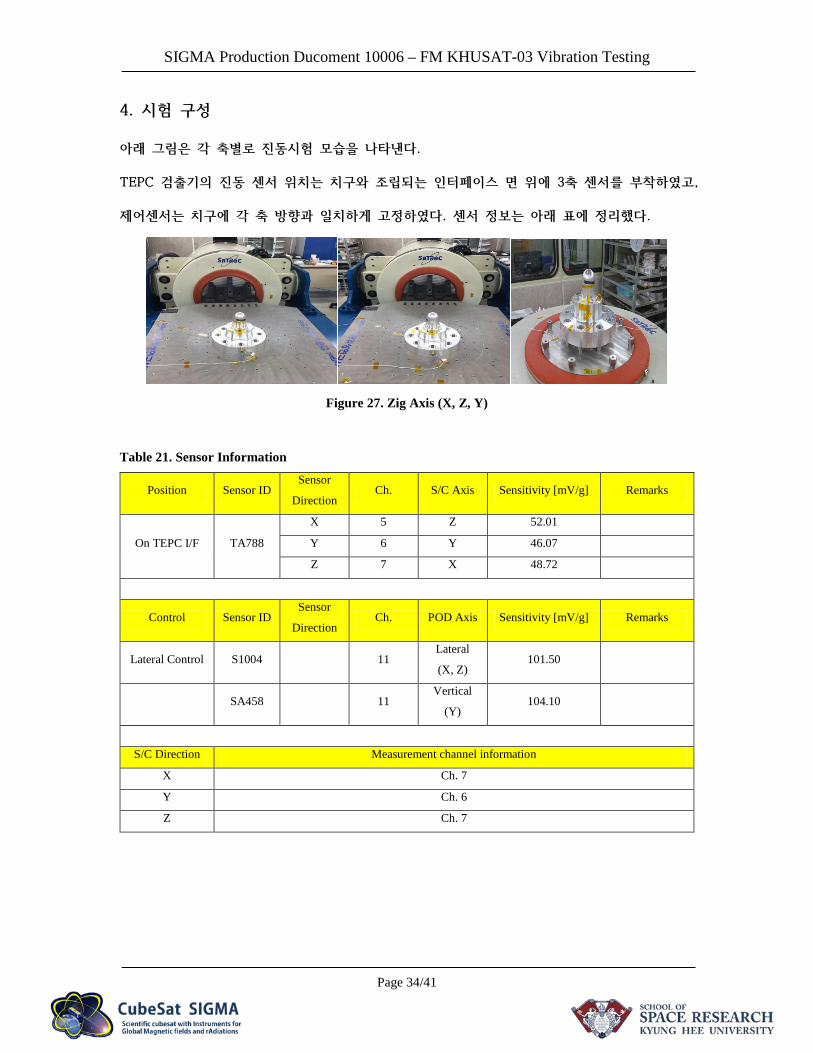
4. 시험 구성
아래 그림은 각 축별로 진동시험 모습을 나타낸다.
TEPC 검출기의 진동 센서 위치는 치구와 조립되는 인터페이스 면 위에 3축 센서를 부착하였고,
제어센서는 치구에 각 축 방향과 일치하게 고정하였다. 센서 정보는 아래 표에 정리했다.
Figure 27. Zig Axis (X, Z, Y)
Table 21. Sensor Information
Position Sensor ID Sensor
Direction Ch. S/C Axis Sensitivity [mV/g] Remarks
On TEPC I/F TA788
X 5 Z 52.01
Y 6 Y 46.07
Z 7 X 48.72
Control Sensor ID Sensor
Direction Ch. POD Axis Sensitivity [mV/g] Remarks
Lateral Control S1004 11 Lateral
(X, Z) 101.50
SA458 11 Vertical
(Y) 104.10
S/C Direction Measurement channel information
X Ch. 7
Y Ch. 6
Z Ch. 7
SIGMA Production Ducoment 10006 – FM KHUSAT-03 Vibration Testing
Page 35/41
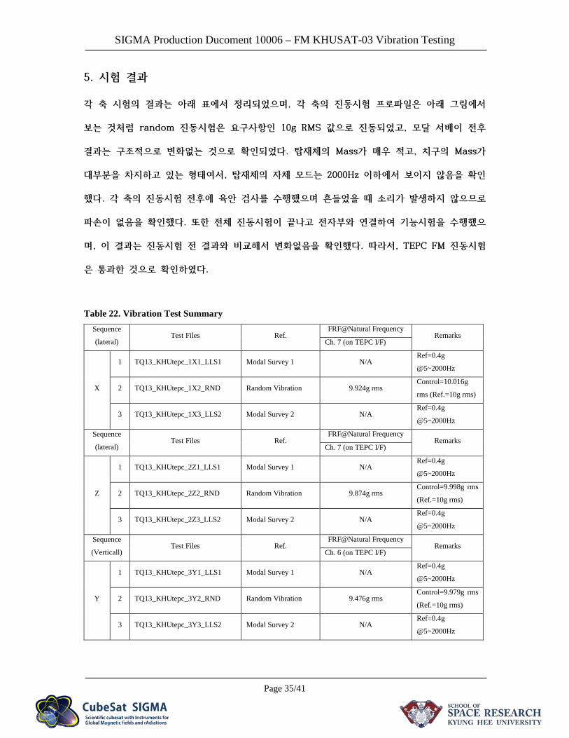
5. 시험 결과
각 축 시험의 결과는 아래 표에서 정리되었으며, 각 축의 진동시험 프로파일은 아래 그림에서
보는 것처럼 random 진동시험은 요구사항인 10g RMS 값으로 진동되었고, 모달 서베이 전후
결과는 구조적으로 변화없는 것으로 확인되었다. 탑재체의 Mass가 매우 적고, 치구의 Mass가
대부분을 차지하고 있는 형태여서, 탑재체의 자체 모드는 2000Hz 이하에서 보이지 않음을 확인
했다. 각 축의 진동시험 전후에 육안 검사를 수행했으며 흔들었을 때 소리가 발생하지 않으므로
파손이 없음을 확인했다. 또한 전체 진동시험이 끝나고 전자부와 연결하여 기능시험을 수행했으
며, 이 결과는 진동시험 전 결과와 비교해서 변화없음을 확인했다. 따라서, TEPC FM 진동시험
은 통과한 것으로 확인하였다.
Table 22. Vibration Test Summary Sequence
(lateral) Test Files Ref.
FRF@Natural Frequency Remarks
Ch. 7 (on TEPC I/F)
X
1 TQ13_KHUtepc_1X1_LLS1 Modal Survey 1 N/A Ref=0.4g
@5~2000Hz
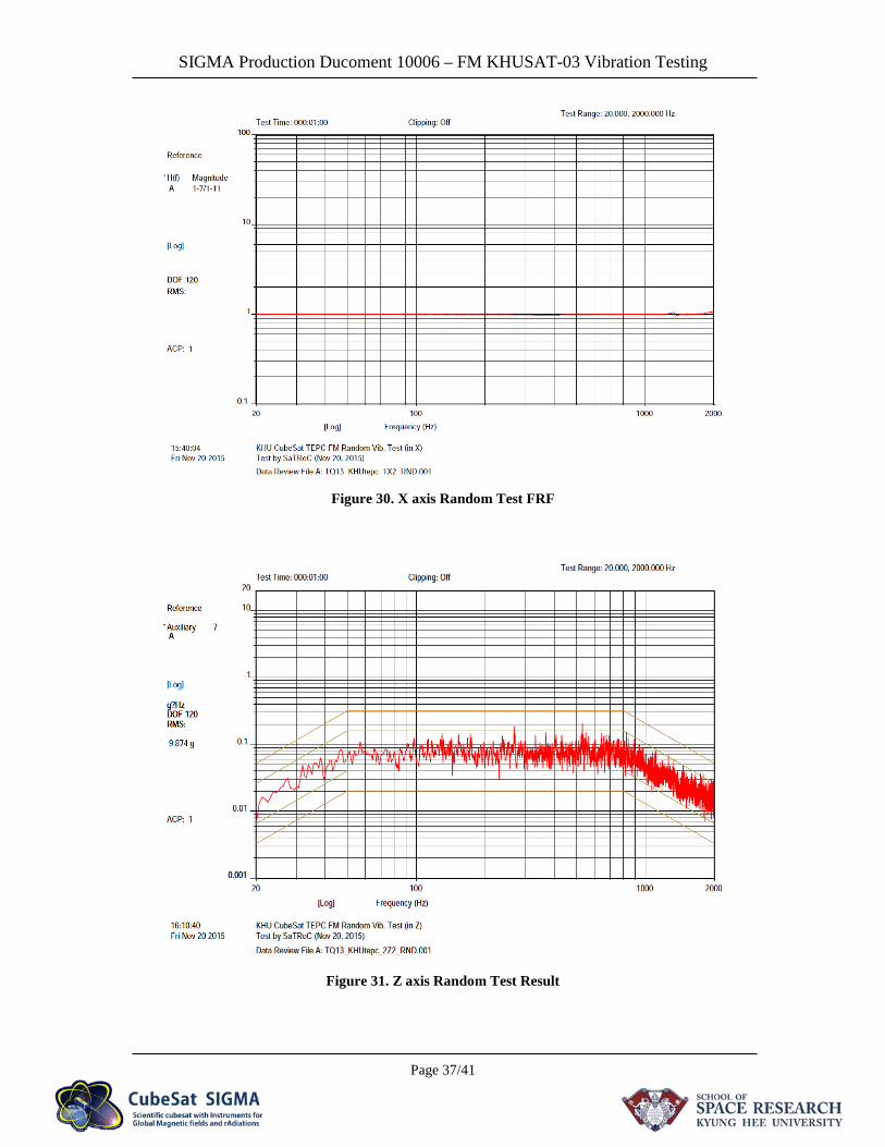
2 TQ13_KHUtepc_1X2_RND Random Vibration 9.924g rms Control=10.016g
rms (Ref.=10g rms)
3 TQ13_KHUtepc_1X3_LLS2 Modal Survey 2 N/A Ref=0.4g
@5~2000Hz
Sequence
(lateral) Test Files Ref.
FRF@Natural Frequency Remarks
Ch. 7 (on TEPC I/F)
Z
1 TQ13_KHUtepc_2Z1_LLS1 Modal Survey 1 N/A Ref=0.4g
@5~2000Hz
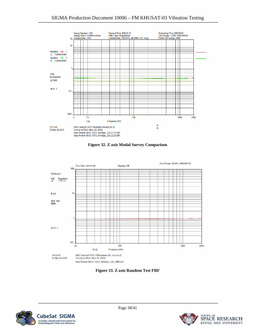
2 TQ13_KHUtepc_2Z2_RND Random Vibration 9.874g rms Control=9.998g rms
(Ref.=10g rms)
3 TQ13_KHUtepc_2Z3_LLS2 Modal Survey 2 N/A Ref=0.4g
@5~2000Hz
Sequence
(Verticall) Test Files Ref.
FRF@Natural Frequency Remarks
Ch. 6 (on TEPC I/F)
Y
1 TQ13_KHUtepc_3Y1_LLS1 Modal Survey 1 N/A Ref=0.4g
@5~2000Hz
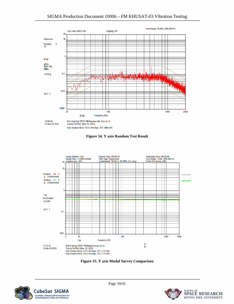
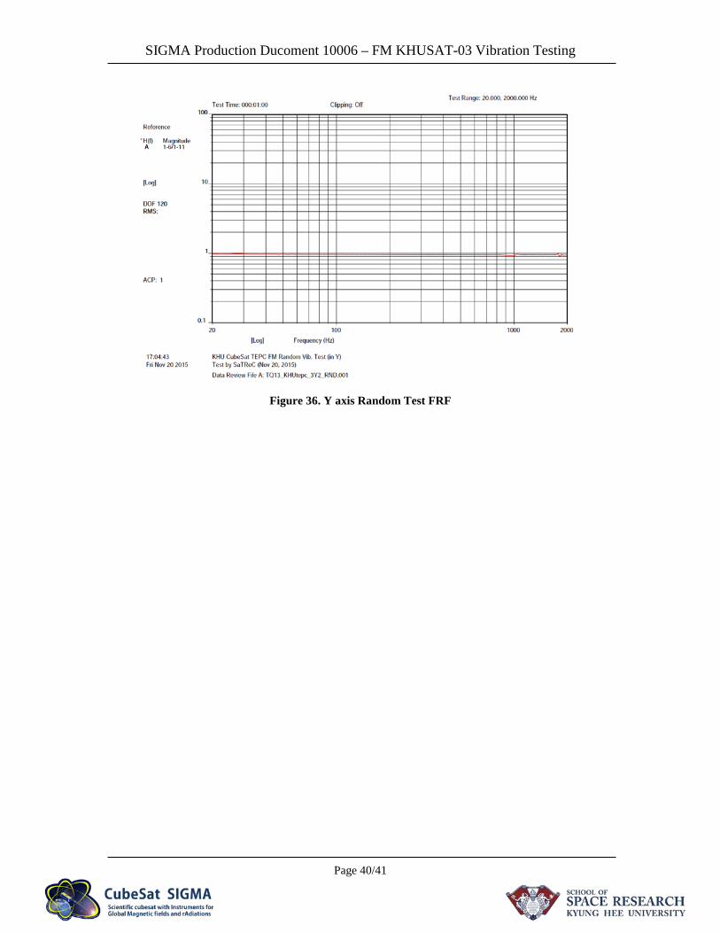
2 TQ13_KHUtepc_3Y2_RND Random Vibration 9.476g rms Control=9.979g rms
(Ref.=10g rms)
3 TQ13_KHUtepc_3Y3_LLS2 Modal Survey 2 N/A Ref=0.4g
@5~2000Hz
SIGMA Production Ducoment 10006 – FM KHUSAT-03 Vibration Testing
Page 36/41
Figure 28. X axis Random Test Result
Figure 29. X axis Modal Survey Comparison
SIGMA Production Ducoment 10006 – FM KHUSAT-03 Vibration Testing
Page 37/41
Figure 30. X axis Random Test FRF
Figure 31. Z axis Random Test Result
SIGMA Production Ducoment 10006 – FM KHUSAT-03 Vibration Testing
Page 38/41
Figure 32. Z axis Modal Survey Comparison
Figure 33. Z axis Random Test FRF
SIGMA Production Ducoment 10006 – FM KHUSAT-03 Vibration Testing
Page 39/41
Figure 34. Y axis Random Test Result
Figure 35. Y axis Modal Survey Comparison
SIGMA Production Ducoment 10006 – FM KHUSAT-03 Vibration Testing
Page 40/41
Figure 36. Y axis Random Test FRF
SIGMA Production Ducoment 10006 – FM KHUSAT-03 Vibration Testing
Page 41/41
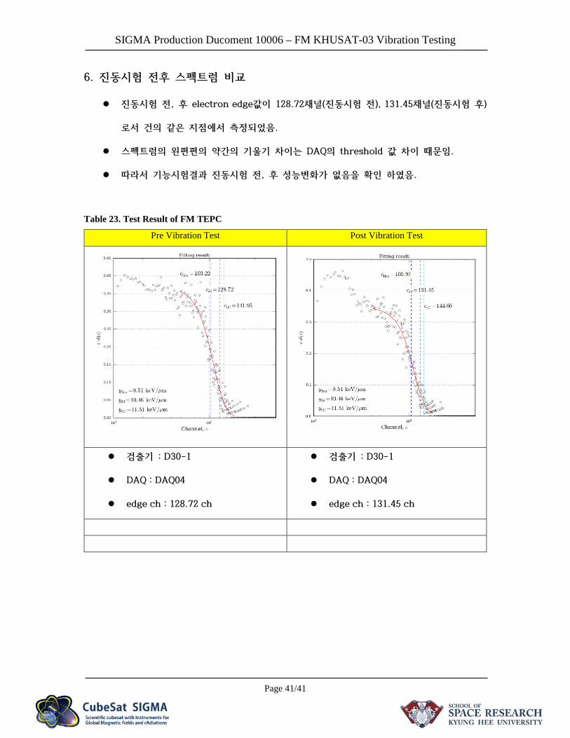
6. 진동시험 전후 스펙트럼 비교
진동시험 전, 후 electron edge값이 128.72채널(진동시험 전), 131.45채널(진동시험 후)
로서 건의 같은 지점에서 측정되었음.
스펙트럼의 왼편편의 약간의 기울기 차이는 DAQ의 threshold 값 차이 때문임.
따라서 기능시험결과 진동시험 전, 후 성능변화가 없음을 확인 하였음.
Table 23. Test Result of FM TEPC
Pre Vibration Test Post Vibration Test
검출기 : D30-1
DAQ : DAQ04
edge ch : 128.72 ch
검출기 : D30-1
DAQ : DAQ04
edge ch : 131.45 ch


![NORMA ISO This is a preview of ISO 10006:2003[S]. Click ...10006-2003[S].pdf · La Norma ISO 10006 fue preparada por el Comité de ISO/TC 176, Gestión y aseguramiento de la calidad,](https://static.fdocuments.in/doc/165x107/5aef6d827f8b9aa17b8dc85b/norma-iso-this-is-a-preview-of-iso-100062003s-click-10006-2003spdfla.jpg)