SPARC Enterprise M4000/M5000 Servers - fujitsu.com · vii Preface This site planning guide...
40
SPARC Enterprise M4000/M5000 Servers Site Planning Guide Part No.: E23586-01 Manual Code: C120-H015-08EN August 2011
Transcript of SPARC Enterprise M4000/M5000 Servers - fujitsu.com · vii Preface This site planning guide...
SPARC Enterprise M4000/M5000 Servers
Site Planning Guide
Part No.: E23586-01 Manual Code: C120-H015-08ENAugust 2011

Copyright © 2007, 2011, Oracle and/or its affiliates. All rights reserved. FUJITSU LIMITED provided technical input and review on portions of this material.Oracle and/or its affiliates and Fujitsu Limited each own or control intellectual property rights relating to products and technology described in this document, and such products, technology and this document are protected by copyright laws, patents, and other intellectual property laws and international treaties.This document and the product and technology to which it pertains are distributed under licenses restricting their use, copying, distribution, and decompilation. No part of such product or technology, or of this document, may be reproduced in any form by any means without prior written authorization of Oracle and/or its affiliates and Fujitsu Limited, and their applicable licensors, if any. The furnishings of this document to you does not give you any rights or licenses, express or implied, with respect to the product or technology to which it pertains, and this document does not contain or represent any commitment of any kind on the part of Oracle or Fujitsu Limited, or any affiliate of either of them.This document and the product and technology described in this document may incorporate third-party intellectual property copyrighted by and/or licensed from the suppliers to Oracle and/or its affiliates and Fujitsu Limited, including software and font technology.Per the terms of the GPL or LGPL, a copy of the source code governed by the GPL or LGPL, as applicable, is available upon request by the End User. Please contact Oracle and/or its affiliates or Fujitsu Limited. This distribution may include materials developed by third parties.Parts of the product may be derived from Berkeley BSD systems, licensed from the University of California. UNIX is a registered trademark in the U.S. and in other countries, exclusively licensed through X/Open Company, Ltd.Oracle and Java are registered trademarks of Oracle and/or its affiliates. Fujitsu and the Fujitsu logo are registered trademarks of Fujitsu Limited. All SPARC trademarks are used under license and are registered trademarks of SPARC International, Inc. in the U.S. and other countries. Products bearing SPARC trademarks are based upon architectures developed by Oracle and/or its affiliates. SPARC64 is a trademark of SPARC International, Inc., used under license by Fujitsu Microelectronics, Inc. and Fujitsu Limited. Other names may be trademarks of their respective owners.United States Government Rights - Commercial use. U.S. Government users are subject to the standard government user license agreements of Oracle and/or its affiliates and Fujitsu Limited and the applicable provisions of the FAR and its supplements.Disclaimer: The only warranties granted by Oracle and Fujitsu Limited, and/or any affiliate of either of them in connection with this document or any product or technology described herein are those expressly set forth in the license agreement pursuant to which the product or technology is provided. EXCEPT AS EXPRESSLY SET FORTH IN SUCH AGREEMENT, ORACLE OR FUJITSU LIMITED, AND/OR THEIR AFFILIATES MAKE NO REPRESENTATIONS OR WARRANTIES OF ANY KIND (EXPRESS OR IMPLIED) REGARDING SUCH PRODUCT OR TECHNOLOGY OR THIS DOCUMENT, WHICH ARE ALL PROVIDED AS IS, AND ALL EXPRESS OR IMPLIED CONDITIONS, REPRESENTATIONS AND WARRANTIES, INCLUDING WITHOUT LIMITATION ANY IMPLIED WARRANTY OF MERCHANTABILITY, FITNESS FOR A PARTICULAR PURPOSE OR NON-INFRINGEMENT, ARE DISCLAIMED, EXCEPT TO THE EXTENT THAT SUCH DISCLAIMERS ARE HELD TO BE LEGALLY INVALID. Unless otherwise expressly set forth in such agreement, to the extent allowed by applicable law, in no event shall Oracle or Fujitsu Limited, and/or any of their affiliates have any liability to any third party under any legal theory for any loss of revenues or profits, loss of use or data, or business interruptions, or for any indirect, special, incidental or consequential damages, even if advised of the possibility of such damages.DOCUMENTATION IS PROVIDED “AS IS” AND ALL EXPRESS OR IMPLIED CONDITIONS, REPRESENTATIONS AND WARRANTIES, INCLUDING ANY IMPLIED WARRANTY OF MERCHANTABILITY, FITNESS FOR A PARTICULAR PURPOSE OR NON-INFRINGEMENT, ARE DISCLAIMED, EXCEPT TO THE EXTENT THAT SUCH DISCLAIMERS ARE HELD TO BE LEGALLY INVALID.
PleaseRecycle

Copyright © 2007, 2011, Oracle et/ou ses sociétés affiliées. Tous droits réservés. FUJITSU LIMITED a fourni et vérifié des données techniques de certaines parties de ce composant.Oracle et/ou ses sociétés affiliées et Fujitsu Limited détiennent et contrôlent chacune des droits de propriété intellectuelle relatifs aux produits et technologies décrits dans ce document. De même, ces produits, technologies et ce document sont protégés par des lois sur le copyright, des brevets, d’autres lois sur la propriété intellectuelle et des traités internationaux.Ce document, le produit et les technologies afférents sont exclusivement distribués avec des licences qui en restreignent l’utilisation, la copie, la distribution et la décompilation. Aucune partie de ce produit, de ces technologies ou de ce document ne peut être reproduite sous quelque forme que ce soit, par quelque moyen que ce soit, sans l’autorisation écrite préalable d’Oracle et/ou ses sociétés affiliées et de Fujitsu Limited, et de leurs éventuels bailleurs de licence. Ce document, bien qu’il vous ait été fourni, ne vous confère aucun droit et aucune licence, expresses ou tacites, concernant le produit ou la technologie auxquels il se rapporte. Par ailleurs, il ne contient ni ne représente aucun engagement, de quelque type que ce soit, de la part d’Oracle ou de Fujitsu Limited, ou des sociétés affiliées de l’une ou l’autre entité.Ce document, ainsi que les produits et technologies qu’il décrit, peuvent inclure des droits de propriété intellectuelle de parties tierces protégés par copyright et/ou cédés sous licence par des fournisseurs à Oracle et/ou ses sociétés affiliées et Fujitsu Limited, y compris des logiciels et des technologies relatives aux polices de caractères.Conformément aux conditions de la licence GPL ou LGPL, une copie du code source régi par la licence GPL ou LGPL, selon le cas, est disponible sur demande par l’Utilisateur final. Veuillez contacter Oracle et/ou ses sociétés affiliées ou Fujitsu Limited. Cette distribution peut comprendre des composants développés par des parties tierces.Des parties de ce produit peuvent être dérivées des systèmes Berkeley BSD, distribués sous licence par l’Université de Californie. UNIX est une marque déposée aux États-Unis et dans d’autres pays, distribuée exclusivement sous licence par X/Open Company, Ltd.Oracle et Java sont des marques déposées d’Oracle Corporation et/ou de ses sociétés affiliées. Fujitsu et le logo Fujitsu sont des marques déposées de Fujitsu Limited. Toutes les marques SPARC sont utilisées sous licence et sont des marques déposées de SPARC International, Inc., aux États-Unis et dans d’autres pays. Les produits portant la marque SPARC reposent sur des architectures développées par Oracle et/ou ses sociétés affiliées. SPARC64 est une marque de SPARC International, Inc., utilisée sous licence par Fujitsu Microelectronics, Inc. et Fujitsu Limited. Tout autre nom mentionné peut correspondre à des marques appartenant à d’autres propriétaires.United States Government Rights - Commercial use. U.S. Government users are subject to the standard government user license agreements of Oracle and/or its affiliates and Fujitsu Limited and the applicable provisions of the FAR and its supplements.Avis de non-responsabilité : les seules garanties octroyées par Oracle et Fujitsu Limited et/ou toute société affiliée de l’une ou l’autre entité en rapport avec ce document ou tout produit ou toute technologie décrits dans les présentes correspondent aux garanties expressément stipulées dans le contrat de licence régissant le produit ou la technologie fournis. SAUF MENTION CONTRAIRE EXPRESSÉMENT STIPULÉE DANS CE CONTRAT, ORACLE OU FUJITSU LIMITED ET LES SOCIÉTÉS AFFILIÉES À L’UNE OU L’AUTRE ENTITÉ REJETTENT TOUTE REPRÉSENTATION OU TOUTE GARANTIE, QUELLE QU’EN SOIT LA NATURE (EXPRESSE OU IMPLICITE) CONCERNANT CE PRODUIT, CETTE TECHNOLOGIE OU CE DOCUMENT, LESQUELS SONT FOURNIS EN L’ÉTAT. EN OUTRE, TOUTES LES CONDITIONS, REPRÉSENTATIONS ET GARANTIES EXPRESSES OU TACITES, Y COMPRIS NOTAMMENT TOUTE GARANTIE IMPLICITE RELATIVE À LA QUALITÉ MARCHANDE, À L’APTITUDE À UNE UTILISATION PARTICULIÈRE OU À L’ABSENCE DE CONTREFAÇON, SONT EXCLUES, DANS LA MESURE AUTORISÉE PAR LA LOI APPLICABLE. Sauf mention contraire expressément stipulée dans ce contrat, dans la mesure autorisée par la loi applicable, en aucun cas Oracle ou Fujitsu Limited et/ou l’une ou l’autre de leurs sociétés affiliées ne sauraient être tenues responsables envers une quelconque partie tierce, sous quelque théorie juridique que ce soit, de tout manque à gagner ou de perte de profit, de problèmes d’utilisation ou de perte de données, ou d’interruptions d’activités, ou de tout dommage indirect, spécial, secondaire ou consécutif, même si ces entités ont été préalablement informées d’une telle éventualité.LA DOCUMENTATION EST FOURNIE « EN L’ÉTAT » ET TOUTE AUTRE CONDITION, DÉCLARATION ET GARANTIE, EXPRESSE OU TACITE, EST FORMELLEMENT EXCLUE, DANS LA MESURE AUTORISÉE PAR LA LOI EN VIGUEUR, Y COMPRIS NOTAMMENT TOUTE GARANTIE IMPLICITE RELATIVE À LA QUALITÉ MARCHANDE, À L’APTITUDE À UNE UTILISATION PARTICULIÈRE OU À L’ABSENCE DE CONTREFAÇON.

Contents
Preface vii
1. Physical Specifications 1–1
1.1 Before Setting Up the Server 1–1
1.2 Server Specifications 1–2
1.2.1 Server Components 1–2
1.2.2 Server Guidelines 1–6
1.2.2.1 Mounting Requirements 1–6
1.2.2.2 Size and Space Specifications 1–6
1.2.2.3 Space for Thermal Clearance 1–9
1.2.3 Access Route 1–9
2. Network Connection, Environmental, and Electrical Specifications 2–1
2.1 Network Connection 2–1
2.1.1 Setup and Network Connection 2–1
2.1.2 Platform and Domain Setup 2–2
2.1.3 Choosing the System Control Network Configuration 2–3
2.2 UPS Interface 2–7
2.2.1 Overview 2–7
2.2.2 Signal Cables 2–7
v

2.2.3 Signal Line Configuration 2–7
2.2.4 Power Supply Conditions 2–9
2.2.4.1 Input Circuit 2–9
2.2.4.2 Output Circuit 2–9
2.2.5 UPS Cable 2–9
2.3 Environmental Requirements 2–10
2.3.1 Ambient Temperature 2–12
2.3.2 Ambient Relative Humidity 2–12
2.3.3 Contamination Specifications 2–13
2.3.4 CPU Types and Server Maximum Power Consumption 2–14
2.4 Electrical and Cooling Specifications 2–15
2.5 Airflow and Heat Dissipation 2–17
2.5.1 Airflow Indicator 2–18
2.6 Facility Power Requirement 2–18
2.6.1 Circuit Breaker Capacity and Characteristics 2–19
2.6.2 Grounding 2–19
vi SPARC Enterprise M4000/M5000 Servers Site Planning Guide • August 2011

Preface
This site planning guide describes the physical, environmental, and electrical specification requirements of the SPARC Enterprise M4000/M5000 servers from Oracle and Fujitsu. This document is intended for authorized service providers. References herein to the M4000 server or M5000 server are references to the SPARC Enterprise M4000 or SPARC Enterprise M5000 server.
Due to the amount of time required to plan and properly prepare a site for installation of these midrange servers, you must fulfill all of the requirements outlined in this manual before your equipment arrives.
This section includes:
■ “SPARC Enterprise M4000/M5000 Servers Documentation” on page vii■ “Text Conventions” on page ix■ “Notes on Safety” on page ix■ “Documentation Feedback” on page x
SPARC Enterprise M4000/M5000 Servers DocumentationAll documents for your sever are available online at the following locations:
■ Sun Oracle software-related manuals (Oracle Solaris OS, and so on):
http://www.oracle.com/technetwork/documentation/index.html
■ Fujitsu documents:
http://www.fujitsu.com/sparcenterprise/manual/
vii

■ Oracle M3000/M4000/M5000/M8000/M9000 servers software documents:
http://www.oracle.com/technetwork/documentation/sparc-mseries-servers-252709.html
■ Oracle M4000 server hardware documents:
http://download.oracle.com/docs/cd/E19855-01/index.html
■ Oracle M5000 server hardware documents:
http://download.oracle.com/docs/cd/E19580-01/index.html
SPARC Enterprise M4000/M5000 Servers Documents
SPARC Enterprise M4000/M5000 Servers Site Planning Guide
SPARC Enterprise Equipment Rack Mounting Guide
SPARC Enterprise M4000/M5000 Servers Getting Started Guide*
* This is a printed document.
SPARC Enterprise M4000/M5000 Servers Overview Guide
SPARC Enterprise M3000/M4000/M5000/M8000/M9000 Servers Important Legal and Safety Information*
SPARC Enterprise M4000/M5000 Servers Safety and Compliance Manual
External I/O Expansion Unit Safety and Compliance Guide
SPARC Enterprise M4000 Server Unpacking Guide
SPARC Enterprise M5000 Server Unpacking Guide
SPARC Enterprise M4000/M5000 Servers Installation Guide
SPARC Enterprise M4000/M5000 Servers Service Manual
External I/O Expansion Unit Installation and Service Manual
SPARC Enterprise M/3000/4000/M5000/M8000/M9000 Servers Administration Guide
SPARC Enterprise M/3000/4000/M5000/M8000/M9000 Servers XSCF User’s Guide
SPARC Enterprise M3000/4000/M5000/M8000/M9000 Servers XSCF Reference Manual
SPARC Enterprise M4000/M5000/M8000/M9000 Servers Dynamic Reconfiguration (DR) User’s Guide
SPARC Enterprise M4000/M5000/M8000/M9000 Servers Capacity on Demand (COD) User’s Guide
SPARC Enterprise M3000/M4000/M5000/M8000/M9000 Servers Product Notes†
† Beginning with the XCP 1100 release.
SPARC Enterprise M4000/M5000 Servers Product Notes
External I/O Expansion Unit Product Notes
SPARC Enterprise M3000/M4000/M5000/M8000/M9000 Servers Glossary
viii SPARC Enterprise M4000/M5000 Servers Site Planning Guide • August 2011

Text ConventionsThis manual uses the following fonts and symbols to express specific types of information.
Notes on SafetyRead the following documents thoroughly before using or handling any SPARC Enterprise M4000/M5000 server.
■ SPARC Enterprise M3000/M4000/M5000/M8000/M9000 Servers Important Legal and Safety Information
■ SPARC Enterprise M4000/M5000 Servers Safety and Compliance Guide
Fonts/symbols Meaning Example
AaBbCc123 What you type, when contrasted with on-screen computer output.This font represents the example of command input in the frame.
XSCF> adduser jsmith
AaBbCc123 The names of commands, files, and directories; on-screen computer output.This font represents the example of command input in the frame.
XSCF> showuser -PUser Name: jsmithPrivileges: useradm
auditadm
Italic Indicates the name of a reference manual.
See the SPARC Enterprise M3000/M4000/M5000/M8000/M9000 Servers XSCF User’s Guide.
" " Indicates names of chapters, sections, items, buttons, or menus.
See Chapter 2, "Environmental and Electrical Specifications."
Preface ix
Documentation FeedbackIf you have any comments or requests regarding this document, go to the following web sites.
■ For Oracle users:
http://www.oraclesurveys.com/se.ashx?s=25113745587BE578
■ For Fujitsu users, refer to this SPARC Enterprise contact:
http://www.fujitsu.com/global/contact/computing/sparce_index.html
x SPARC Enterprise M4000/M5000 Servers Site Planning Guide • August 2011

CHAPTER 1
Physical Specifications
The chapter contains the following sections:
■ Section 1.1, “Before Setting Up the Server” on page 1-1
■ Section 1.2, “Server Specifications” on page 1-2
1.1 Before Setting Up the ServerPrior to server installation, confirm that the requirements in TABLE 1-1 have been met.
TABLE 1-1 Preinstallation Requirements
Checklist Check
Server Components
• Has the server configuration been determined?
• What is the total number of servers?
Training • Have system administrators and operators taken the necessary training courses?
Environmental • Does the computer room environment meet the temperature and humidity specifications (Section 2.5, “Airflow and Heat Dissipation” on page 2-17)?
• Can the computer room environment specifications be maintained satisfactorily?
• Is the computer room secured?
• Is additional fire suppression equipment required?
Facility Power • Have you determined voltage for server equipment rack and peripheral equipment racks?
• Have sufficient power receptacles been ordered for each server, monitor, and peripheral?
• Are the power receptacles within 3.5 meters (11.5 feet) of the equipment rack?
1-1
1.2 Server SpecificationsThis section provides information about the physical characteristics of both midrange servers, including dimensions, space needs, cable sizes, and limitations.
1.2.1 Server ComponentsFIGURE 1-1 illustrates the SPARC Enterprise M4000 server.
Physical Specifications
• Has the server location been established?
• Does the equipment floor layout meet the equipment maintenance access requirements (Section 1.2.2.2, “Size and Space Specifications” on page 1-6)?
• Will the equipment be positioned so that the exhaust air of one device does not enter the air inlet of another?
Access Route • Has the access route been checked for clearances of the packaged server (Section 1.2.3, “Access Route” on page 1-9)?
• Has a proper pallet jack been checked for weight limitation for moving the server (Section 1.2.3, “Access Route” on page 1-9)?
• Has the elevator been checked for clearances and weight restrictions of the packaged server (Section 1.2.3, “Access Route” on page 1-9)?
Network Specification
• Have you determined necessary information for your network connections (Section 2.1, “Network Connection” on page 2-1)?
TABLE 1-1 Preinstallation Requirements (Continued)
Checklist Check
1-2 SPARC Enterprise M4000/M5000 Servers Site Planning Guide • August 2011
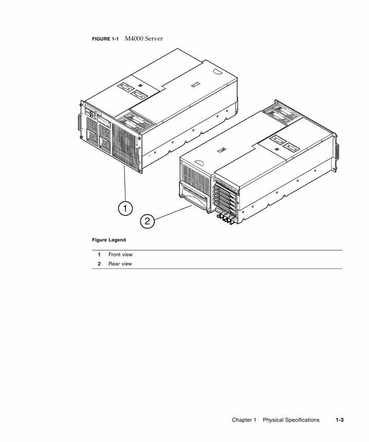
FIGURE 1-1 M4000 Server
Figure Legend
1 Front view
2 Rear view
Chapter 1 Physical Specifications 1-3
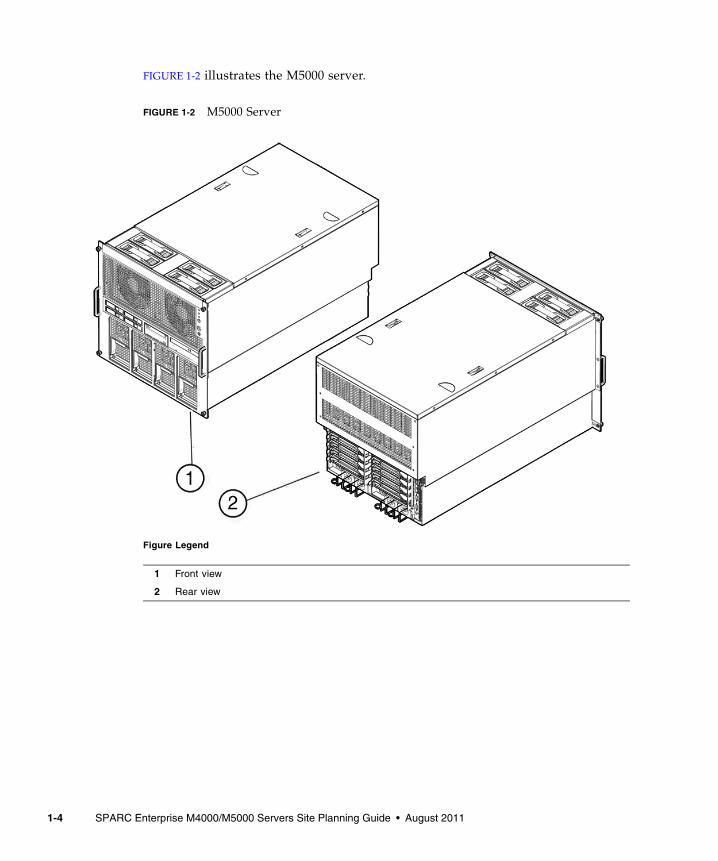
FIGURE 1-2 illustrates the M5000 server.
FIGURE 1-2 M5000 Server
Figure Legend
1 Front view
2 Rear view
1-4 SPARC Enterprise M4000/M5000 Servers Site Planning Guide • August 2011

TABLE 1-2 lists the maximum configurations for midrange servers.
TABLE 1-2 Components for Midrange Servers
Component M4000 Server M5000 Server
Power supply units 2 4
eXtended System Control Facility Unit (XSCFU)
1 1
Fans 4 4
Motherboard unit 1 1
CPU modules 2 4
• CPU chips (SPARC64 VI, SPARC64 VII, SPARC64 VII+)
4 8
Memory boards 4 8
• Memory module 32 64
I/O unit 1 2
• PCI-Express cassettes 4 8
• PCI-X cassette 1 2
CD-RW/DVD-RW drive unit 1 1
Hard disk drive 2 4
Tape drive unit (optional) 1 1
Chapter 1 Physical Specifications 1-5

1.2.2 Server GuidelinesAs you plan your space needs for these midrange servers in qualified equipment racks, keep these conditions in mind:
■ Each midrange server requires its own power cords, connected to separate power outlets. See Chapter 2, Network Connection, Environmental, and Electrical Specifications for details on electrical requirements.
■ Circuit breakers are supplied by the customer as required by local, state, or national electrical codes.
■ Both midrange servers require electrical circuits that are grounded to earth.
1.2.2.1 Mounting Requirements
Both midrange servers are designed to be mounted in qualified equipment racks. For more detail on mounting requirements, refer to the SPARC Enterprise M4000/M5000 Servers Installation Guide for complete installation details and the SPARC Enterprise Equipment Rack Mounting Guide for mounting requirements.
1.2.2.2 Size and Space Specifications
For maintenance access, refer to the SPARC Enterprise Equipment Rack Mounting Guide for exact measurements.
FIGURE 1-3 shows an example of the maintenance access area for midrange servers in a qualified equipment rack.
1-6 SPARC Enterprise M4000/M5000 Servers Site Planning Guide • August 2011
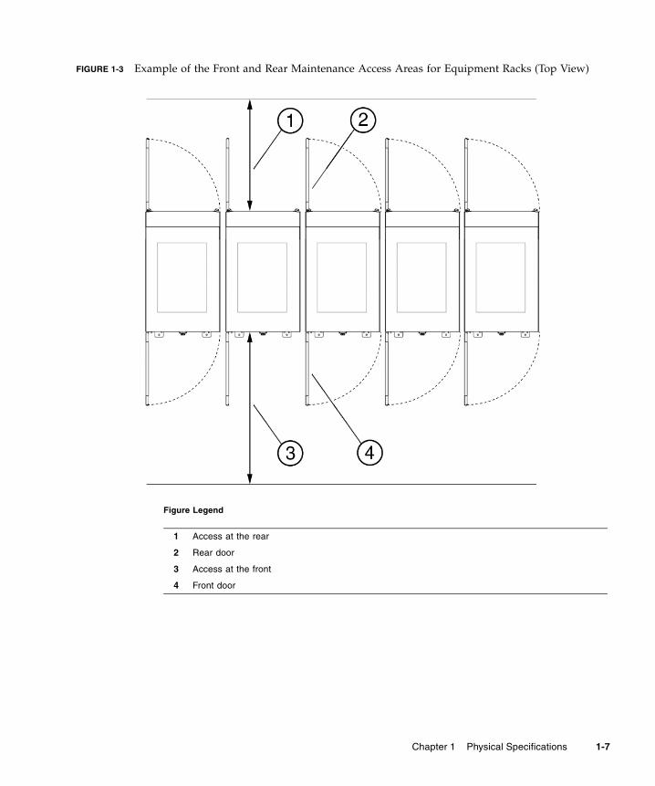
FIGURE 1-3 Example of the Front and Rear Maintenance Access Areas for Equipment Racks (Top View)
Figure Legend
1 Access at the rear
2 Rear door
3 Access at the front
4 Front door
Chapter 1 Physical Specifications 1-7
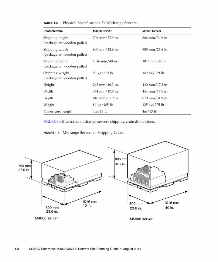
FIGURE 1-4 illustrates midrange servers shipping crate dimensions.
FIGURE 1-4 Midrange Servers in Shipping Crates
TABLE 1-3 Physical Specifications for Midrange Servers
Characteristic M4000 Server M5000 Server
Shipping height (package on wooden pallet)
709 mm/27.9 in. 886 mm/34.9 in.
Shipping width (package on wooden pallet)
600 mm/23.6 in. 600 mm/23.6 in.
Shipping depth (package on wooden pallet)
1016 mm/40 in. 1016 mm/40 in.
Shipping weight (package on wooden pallet)
99 kg/219 lb 149 kg/329 lb
Height 263 mm/10.3 in. 440 mm/17.3 in.
Width 444 mm/17.5 in. 444 mm/17.5 in.
Depth 810 mm/31.9 in. 810 mm/31.9 in.
Weight 84 kg/185 lb 125 kg/275 lb
Power cord length 4m/13 ft 4m/13 ft
1016 mm40 in.
886 mm
600 mm23.6 in.
1016 mm40 in.
34.9 in.709 mm
27.9 in.
M4000 server M5000 server
23.6 in.600 mm
1-8 SPARC Enterprise M4000/M5000 Servers Site Planning Guide • August 2011

1.2.2.3 Space for Thermal Clearance
Both midrange servers must maintain the minimum thermal distance between the rear of the server in an equipment rack, and any obstructions or walls. For thermal clearance requirements during operation, refer to the SPARC Enterprise Equipment Rack Mounting Guide.
1.2.3 Access RouteIf your existing loading dock meets height or ramp requirements for a standard freight carrier truck, you can use a pallet jack to unload the server. If not, you must provide a standard forklift or other means to unload the server, or request the server be shipped in a truck with a lift gate.
All servers not shipped in an equipment rack should be lifted only by proper computer-lifting equipment to prevent personal injury or damage to system equipment.
Each server that is not preinstalled in an equipment rack is shipped in a separate crate. A pallet jack is required to move each shipping crate to the server location.
Leave each server in its shipping crate until it reaches its final destination. If the crate does not fit through the planned access route, partially disassemble it.
The entire access route to your computer room should be free of raised patterns that can cause vibration. The route must meet the following requirements:
■ Minimum door height
■ Minimum elevator depth
■ Maximum incline of 10 degrees
■ Minimum elevator, pallet jack, and floor loading capacity
Refer to the SPARC Enterprise Equipment Rack Mounting Guide for specific requirements for your equipment rack.
Chapter 1 Physical Specifications 1-9

1-10 SPARC Enterprise M4000/M5000 Servers Site Planning Guide • August 2011
CHAPTER 2
Network Connection, Environmental, and Electrical Specifications
This chapter contains the network connection, environmental, and electrical specifications for the SPARC Enterprise M4000/M5000 servers from Oracle and Fujitsu.
■ Section 2.1, “Network Connection” on page 2-1
■ Section 2.2, “UPS Interface” on page 2-7
■ Section 2.3, “Environmental Requirements” on page 2-10
■ Section 2.4, “Electrical and Cooling Specifications” on page 2-15
■ Section 2.5, “Airflow and Heat Dissipation” on page 2-17
■ Section 2.6, “Facility Power Requirement” on page 2-18
2.1 Network ConnectionThis section provides an overview of the midrange servers network setup for server startup and network connections. For more information on network connection, refer to the SPARC Enterprise M4000/M5000 Servers Installation Guide.
2.1.1 Setup and Network Connection The serial port on the eXtended System Control Facility Unit (XSCFU) is used to monitor the boot process and to modify the XSCFU network settings so that the local area network (LAN) ports can be used to connect to a system control network.
2-1
A system control network is a secure LAN that connects the XSCFU to the system administrator’s management console. This connection can be done directly but is usually done through a hub or switch specific to the system control network. Administration directly over the serial port is used to initially configure the LAN ports.
The following network connections must be available:
■ One serial console connection:
■ Baud rate: 9600 bps
■ Data length: 8 bit
■ Parity: None
■ Stop: 1 bit
■ Flow control: None
■ Delay: Except for 0
■ Two 10/100BASE-T Ethernet ports
■ One 10/100BASE-T Ethernet connection per domain
Note – The XSCF Ethernet port is IEEE 802.3i and IEEE 802.3u compliant. This requires auto-negotiation for the port into which it terminates.
2.1.2 Platform and Domain Setup The following information is required when installing midrange servers:
■ For any platform:
■ Netmask
■ Gateway
■ DNS Domain
■ Loghost
■ For each service processor and each domain:
■ Host name
2-2 SPARC Enterprise M4000/M5000 Servers Site Planning Guide • August 2011
2.1.3 Choosing the System Control Network ConfigurationIn determining the system control network configuration, consider the following:
■ The IP address of each LAN port can be assigned in compliance with the existing environment and modified from the default Class-B private address.
■ The customer may use a dual- or single-power feed option.
■ The customer may segregate the LAN port or network for access by field engineers. Or the field engineer access may be through the serial port in the event that maintenance is required.
There are three common system control network configurations depending upon the site requirements:
■ Configuration A (Basic)
■ Configuration B (Limited)
■ Configuration C (Maximum)
Chapter 2 Network Connection, Environmental, and Electrical Specifications 2-3

Configuration A (Basic) – Only one of the two LAN ports is used, leaving the serial port and the other LAN port for use as maintenance ports. The same switch is used for system administration and remote services, so switch failure means system control network failure.
FIGURE 2-1 Configuration A (Basic)
Systemadministration
Remoteservices
LAN
Firewall
Serial
Switch
UPC #1
UPC #0
2-4 SPARC Enterprise M4000/M5000 Servers Site Planning Guide • August 2011

Configuration B (Limited Redundancy) – Both LAN ports are used, one for system administration and the second for remote messaging. If one switch goes down, errors can still be reported. The serial port and a port on the remote services switch are available as maintenance ports.
FIGURE 2-2 Configuration B (Limited Redundancy)
Switch
Switch
Firewall
Maintenanceport
Systemadministration
Remote services
Serial
LAN 1
LAN 0
UPC #1
UPC #0
Chapter 2 Network Connection, Environmental, and Electrical Specifications 2-5
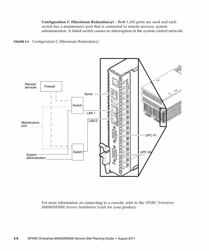
Configuration C (Maximum Redundancy) – Both LAN ports are used and each switch has a maintenance port that is connected to remote services, system administration. A failed switch causes no interruption in the system control network.
FIGURE 2-3 Configuration C (Maximum Redundancy)
For more information on connecting to a console, refer to the SPARC Enterprise M4000/M5000 Servers Installation Guide for your product.
LAN 1
Switch
Switch
Maintenanceport
Firewall
Systemadministration
Remoteservices
Serial
LAN 0
UPC #1
UPC #0
2-6 SPARC Enterprise M4000/M5000 Servers Site Planning Guide • August 2011
2.2 UPS InterfaceThis section describes the Uninterruptible Power Supply (UPS) interface which connects to and controls the UPS.
2.2.1 OverviewA UPS unit is used to provide a stable supply of power to the system in the event of a power failure or an extensive power interruption.
When a failure is detected in the supply of power, an error can be reported to the server through the signal cable connection between a UPC port on the server and a UPS that has the UPC interface. Then the server can execute emergency shutdown processing to safely shut down the system.
2.2.2 Signal CablesPrepare shielded and paired cables that have the following specifications:
■ DC resistance (roundtrip/1 pair): 400 Ω/km or less
■ Cable length: Up to 10 m (33 ft)
2.2.3 Signal Line ConfigurationThis section describes signal definitions and electrical specifications.
FIGURE 2-4 shows the signal line configuration when connected to a UPS.
TABLE 2-1 defines these signal lines.
Chapter 2 Network Connection, Environmental, and Electrical Specifications 2-7

FIGURE 2-4 Connection with UPS
TABLE 2-1 UPS Interface Signals
ON: Indicates contacts are closed
OFF: Indicates contacts are open
Note1: Use a UPS capable of normal battery power supply operation for at least 10 to 60 seconds after this signal is turned on.
Note2: Use a UPS capable of normal battery power supply output without turning on the *ACOFF in an instantaneous commercial AC power failure lasting two seconds or less.
Signal Name Definitions Pin Number Remarks
*BPS/*UALM Signal indicates faulty UPS conditions 6 Normal: OFFFailure: ON
*BTL Signal provides a warning of a low battery level and a pending UPS failure.
7 Normal: OFFWarning: ON(Note1)
*ACOFF Signal indicates power failure at the commercial AC supply connector to the UPS
9 Normal: OFFPower failure: ON(Note2)
SG Signal ground 5
ER Signal indicates the main unit is running (Equipment Ready)
1 Do not connect to ERsignal pin.
UPS cableUPS Server
*BTL
*ACOFF
SG
7
6
9
5
*BPS/*UALM
1
2-8 SPARC Enterprise M4000/M5000 Servers Site Planning Guide • August 2011

2.2.4 Power Supply ConditionsTABLE 2-2 and TABLE 2-3 list the electrical specifications for the UPS interface.
2.2.4.1 Input Circuit
Limit the signal-line chatter period to 1ms or less.
2.2.4.2 Output Circuit
2.2.5 UPS CableThe UPS cable specifications are as follows:
■ Connector type
■ D-SUB9 pin Male (install side: Female)
■ DEU-9PF-F0
■ Terminal array
FIGURE 2-5 identifies pin signals of the UPC connector and the UPS cable.
Do not use the unused pins (pin number 2, 3, 4 and 8 in the following diagram). Cable side shown in FIGURE 2-5.
TABLE 2-2 Electrical Specifications
Signal Name Input Conditions
*BPS/*UALM No voltage relay contactContact rating DC 12 V, 10 mA or more (maximum 0.5A)Use of metallic contact, or lead relay is recommended.
*BTL
*ACOFF
TABLE 2-3 Electrical Specifications
Signal Name Output Conditions
ER Output Voltage
VOH 3.1 VDC (min.)
VOL 0 to 0.4 VDC (max)
Output Current
IOH - 4 mA (max)
IOL 4 mA (max)
Chapter 2 Network Connection, Environmental, and Electrical Specifications 2-9

FIGURE 2-5 Corresponding Terminals in UPC Port and the UPS Cable
Note – If you need UPC cables, make arrangements separately. For details, contact your sales representatives.
2.3 Environmental RequirementsBoth midrange servers can be installed in an environment with the operating ranges shown in TABLE 2-4.
The design of your environmental control system—such as computer room air-conditioning units—must ensure that intake air to the servers complies with the limits specified in this section.
To avoid overheating:
■ Guard against directing any warm air toward the front of the equipment rack.
■ Guard against directing warm air toward the server air intake.
TABLE 2-4 lists the environmental requirements.
Note: Do not connect to ER signal pin.
(Note)
*BTL
*BPS/*UALM
*ACOFF
SG
ER
UPS cable side
*BTL
*BPS/*UALM*ACOFF
SG
1
2
3
4
5
6
7
8
9
Signal name
---
---
---
---
UPC port side
Pin #
2-10 SPARC Enterprise M4000/M5000 Servers Site Planning Guide • August 2011
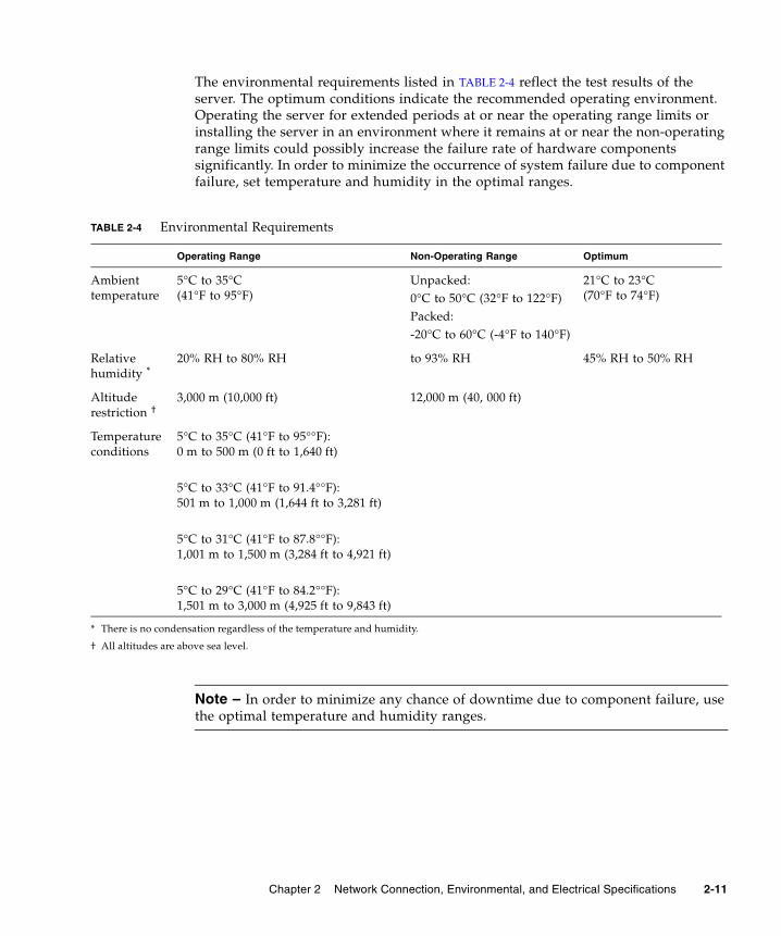
The environmental requirements listed in TABLE 2-4 reflect the test results of the server. The optimum conditions indicate the recommended operating environment. Operating the server for extended periods at or near the operating range limits or installing the server in an environment where it remains at or near the non-operating range limits could possibly increase the failure rate of hardware components significantly. In order to minimize the occurrence of system failure due to component failure, set temperature and humidity in the optimal ranges.
Note – In order to minimize any chance of downtime due to component failure, use the optimal temperature and humidity ranges.
TABLE 2-4 Environmental Requirements
Operating Range Non-Operating Range Optimum
Ambient temperature
5°C to 35°C(41°F to 95°F)
Unpacked:0°C to 50°C (32°F to 122°F)Packed:-20°C to 60°C (-4°F to 140°F)
21°C to 23°C(70°F to 74°F)
Relative humidity *
* There is no condensation regardless of the temperature and humidity.
20% RH to 80% RH to 93% RH 45% RH to 50% RH
Altitude restriction †
† All altitudes are above sea level.
3,000 m (10,000 ft) 12,000 m (40, 000 ft)
Temperature conditions
5°C to 35°C (41°F to 95°°F):0 m to 500 m (0 ft to 1,640 ft)
5°C to 33°C (41°F to 91.4°°F):501 m to 1,000 m (1,644 ft to 3,281 ft)
5°C to 31°C (41°F to 87.8°°F):1,001 m to 1,500 m (3,284 ft to 4,921 ft)
5°C to 29°C (41°F to 84.2°°F):1,501 m to 3,000 m (4,925 ft to 9,843 ft)
Chapter 2 Network Connection, Environmental, and Electrical Specifications 2-11

2.3.1 Ambient TemperatureThe ambient temperature range of 21°C to 23°C (70°F to 74°F) is optimal for server reliability and operator comfort levels. Most computer equipment can operate within a wide temperature range, but a level near 22°C (72°F) is desirable because it is easier to maintain safe associated relative humidity levels at this temperature. Operating in this temperature range provides a safety buffer in the event the air conditioning systems go down for a period of time.
2.3.2 Ambient Relative HumidityAmbient relative humidity levels between 45 percent and 50 percent are the most suitable for safe data processing operations. Most data processing equipment can operate within a fairly wide environmental range (20 percent to 80 percent), but the optimal goal should be between 45 percent to 50 percent for the following reasons:
■ Optimal range helps protect computer systems from corrosivity problems associated with high humidity levels.
■ Optimal range provides the greatest operating time buffer in the event of an air conditioner control failure.
■ This range helps avoid failures or temporary malfunctions caused by intermittent interference from static discharges that might occur when relative humidity is too low.
Electrostatic discharge (ESD) is easily generated and less easily dissipated in areas where the relative humidity is below 35 percent. ESD becomes critical when humidity levels drop below 30 percent. The 5 percent relative humidity range might seem unreasonably tight when compared to the guidelines used in typical office environments or other loosely controlled areas. However, it is not as difficult to maintain in a data center because of the high efficiency vapor barrier and low rate of air changes normally present.
2-12 SPARC Enterprise M4000/M5000 Servers Site Planning Guide • August 2011
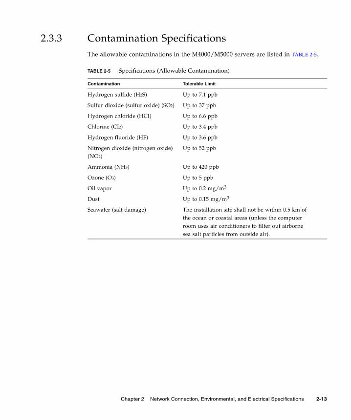
2.3.3 Contamination SpecificationsThe allowable contaminations in the M4000/M5000 servers are listed in TABLE 2-5.
TABLE 2-5 Specifications (Allowable Contamination)
Contamination Tolerable Limit
Hydrogen sulfide (H2S) Up to 7.1 ppb
Sulfur dioxide (sulfur oxide) (SO2) Up to 37 ppb
Hydrogen chloride (HCI) Up to 6.6 ppb
Chlorine (CI2) Up to 3.4 ppb
Hydrogen fluoride (HF) Up to 3.6 ppb
Nitrogen dioxide (nitrogen oxide)(NO2)
Up to 52 ppb
Ammonia (NH3) Up to 420 ppb
Ozone (O3) Up to 5 ppb
Oil vapor Up to 0.2 mg/m3
Dust Up to 0.15 mg/m3
Seawater (salt damage) The installation site shall not be within 0.5 km ofthe ocean or coastal areas (unless the computerroom uses air conditioners to filter out airbornesea salt particles from outside air).
Chapter 2 Network Connection, Environmental, and Electrical Specifications 2-13

2.3.4 CPU Types and Server Maximum Power ConsumptionThis section describes the CPU types and the maximum power consumption of the server.
There are four types of CPU. The power specifications of the M4000 and M5000 servers vary depending on the CPU type and the system configuration.
TABLE 2-6 and TABLE 2-7 list the specifications of maximum power consumption, apparent power, and heat dissipation by the type of CPU. The figures represent the system configuration described below the tables, in which every CPU Modules (CPUM) is mounted with the same CPU.
Note – Values in TABLE 2-6 and TABLE 2-7 are rounded to the nearest whole numbers.
TABLE 2-6 CPU Types and Maximum Power Consumption on the M4000 Server*
* M4000 system configuration: CPUM x 2, MEMB x 4, 8GB DIMM x 32, HDD x 2, PCIe x 4, PCI-X x 1, DAT x 1.
CPU Type Frequency (GHz) NumberPower Consumption (W)
Apparent Power (VA) Heat Dissipation (KJ/h)
SPARC 64 VI processor 2.15 4 1556 1621 5602
SPARC 64 VII processor 2.4/2.53 4 1656 1725 5962
SPARC 64 VII+ processor 2.66 4 1692 1763 6091
TABLE 2-7 CPU Types and Maximum Power Consumption on the M5000 Server*
* M5000 system configuration: CPUM x 4, MEMB x 8, 8GB DIMM x 64, HDD x 4, PCIe x 8, PCI-X x 1, DAT x 1.
CPU Type Frequency (GHz) NumberPower Consumption (W)
Apparent Power (VA) Heat Dissipation (KJ/h)
SPARC 64 VI processor 2.15 8 2998 3123 10793
SPARC 64 VII processor 2.4/2.53 8 3198 3331 11513
SPARC 64 VII+ processor 2.66 8 3270 3406 11772
2-14 SPARC Enterprise M4000/M5000 Servers Site Planning Guide • August 2011

2.4 Electrical and Cooling SpecificationsThis section provides guidelines and requirements for cooling the midrange servers. See TABLE 2-8 for the electrical and cooling specifications.
Be aware of the following server cooling rules and guidelines:
■ The room should have sufficient air-conditioning capacity to support the cooling needs of the entire server.
■ The air-conditioning system should have controls that prevent excessive temperature changes.
Note – The power numbers in TABLE 2-8 are maximums and are based on fully configured servers. Actual numbers might vary according to your server configuration.
TABLE 2-8 Midrange Servers Electrical Specifications
M4000 Server M5000 Server
Number of power cords 2 (1 power cord per power supply unit) 4 (1 power cord per power supply unit)
Redundancy 1 + 1 redundantSecond power supply is redundant at 200 VAC
2 + 2 redundantSecond and fourth power supplies are redundant at 200 VAC
Input voltage 100–127 VAC200–240 VAC
100–127 VAC200–240 VAC
Maximum current 24.0A at 100–127 VAC (12A/cord)12.0A at 200–240 VAC (12A/cord)
48A at 100–127 VAC (12A/cord)24A at 200–240 VAC (12A/cord)
Frequency 50–60 Hz 50–60 Hz
Power draw (maximum) 1,692W (2 power cords) 3,270W (4 power cords)
Rush current per PSU* 50A 50A
Leakage current per PSU† 1.5mA 1.5mA
Chapter 2 Network Connection, Environmental, and Electrical Specifications 2-15
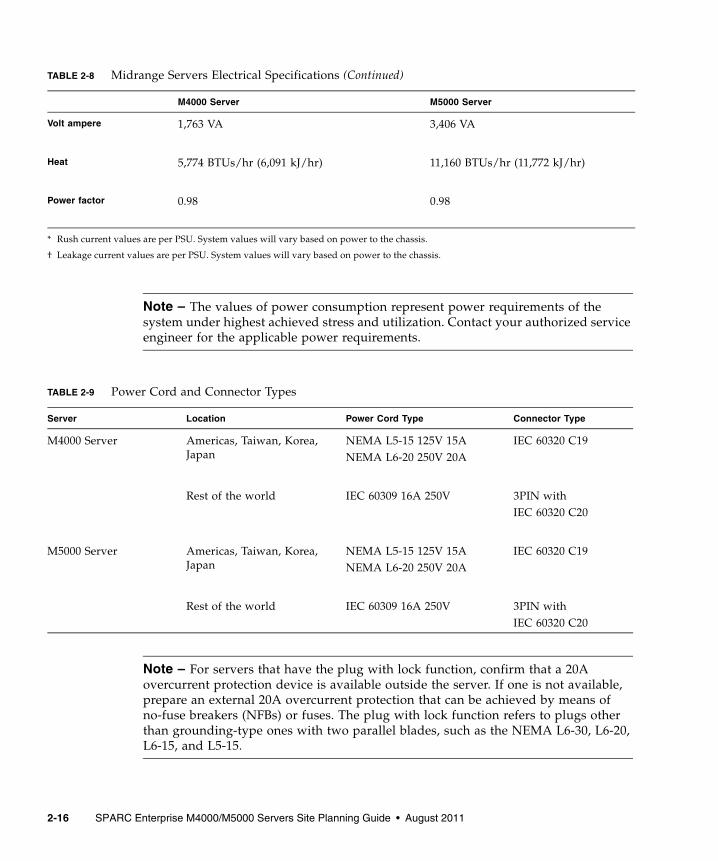
Note – For servers that have the plug with lock function, confirm that a 20A overcurrent protection device is available outside the server. If one is not available, prepare an external 20A overcurrent protection that can be achieved by means of no-fuse breakers (NFBs) or fuses. The plug with lock function refers to plugs other than grounding-type ones with two parallel blades, such as the NEMA L6-30, L6-20, L6-15, and L5-15.
Volt ampere 1,763 VA 3,406 VA
Heat 5,774 BTUs/hr (6,091 kJ/hr) 11,160 BTUs/hr (11,772 kJ/hr)
Power factor 0.98 0.98
* Rush current values are per PSU. System values will vary based on power to the chassis.
† Leakage current values are per PSU. System values will vary based on power to the chassis.
Note – The values of power consumption represent power requirements of the system under highest achieved stress and utilization. Contact your authorized service engineer for the applicable power requirements.
TABLE 2-9 Power Cord and Connector Types
Server Location Power Cord Type Connector Type
M4000 Server Americas, Taiwan, Korea, Japan
NEMA L5-15 125V 15ANEMA L6-20 250V 20A
IEC 60320 C19
Rest of the world IEC 60309 16A 250V 3PIN with IEC 60320 C20
M5000 Server Americas, Taiwan, Korea, Japan
NEMA L5-15 125V 15A NEMA L6-20 250V 20A
IEC 60320 C19
Rest of the world IEC 60309 16A 250V 3PIN with IEC 60320 C20
TABLE 2-8 Midrange Servers Electrical Specifications (Continued)
M4000 Server M5000 Server
2-16 SPARC Enterprise M4000/M5000 Servers Site Planning Guide • August 2011

2.5 Airflow and Heat DissipationThe maximum rate of heat release from fully configured midrange servers is listed in TABLE 2-10.
Both midrange servers have been designed to function while mounted in a natural convection airflow. The following rules must be followed to meet the environmental specification.
■ Ensure adequate airflow through the server.
■ The M4000 server uses internal fans that can achieve a total airflow of 300 cubic feet of air per minute (cfm)/8.5 cubic meter per minute in normal operating conditions.
■ The M5000 server uses internal fans that can achieve a total airflow of 600 cfm/ 16.99 cubic meter per minute in normal operating conditions.
■ The server has front-to-back cooling. The air inlet is at the front of the server. The exhaust exits from the rear of the server.
■ Allow a minimum clearance of 36 inches (914 mm) at the front and 914 mm (36 inches) at the rear of the server for adequate ventilation.
Ensure that additional equipment installed in the equipment rack does not exceed environmental limits at the air inlet. The environmental limits assume the server is operating in the equipment rack with ventilated doors closed.
TABLE 2-10 Heat Dissipation
Server Configuration Heat Dissipation
M4000 server 2 CPU modules, 256 Gbytes memory 5,774 BTUs/hr (6,091 kJ/hr)
M5000 server 4 CPU modules, 512 Gbytes memory 11,160 BTUs/hr (11,772 kJ/hr)
Chapter 2 Network Connection, Environmental, and Electrical Specifications 2-17

2.5.1 Airflow IndicatorThe airflow indicator indicates the amount of air exhausted from the server while the M4000/M5000 servers are up and running. The values do not include the peripheral devices. To display the amount of exhaust air, use the showenvironment air command.
Note – The showenvironment air command displays the calculated airflow based on the fan speed such as Low speed or High speed etc. The fan speed is displayed by the showenvironment Fan command.
For details of the showenvironment(8) command, refer to the man page. For installation details of the M4000/M5000 servers, see the SPARC Enterprise M4000/M5000 Servers Site Planning Guide and the SPARC Enterprise M4000/M5000 Servers Installation Guide.
You can also obtain the exhaust air data using the SNMP agent function. To obtain the data of exhaust air using the SNMP agent function, install the latest XSCF extension MIB definition file to the SNMP manager. For details on the XSCF extension MIB definition file, see the SPARC Enterprise M3000/M4000/M5000/M8000/M9000 Servers XSCF User’s Guide
2.6 Facility Power RequirementTo prevent catastrophic failures, the design of your power system must ensure that adequate power is provided to your midrange servers. Use dedicated AC breaker panels for all power circuits that supply power to your server. Electrical work and installations must comply with applicable local, state, or national electrical codes.
EXAMPLE 2-1
XSCF> showenvironment airAir Flow:294 CMH
2-18 SPARC Enterprise M4000/M5000 Servers Site Planning Guide • August 2011

2.6.1 Circuit Breaker Capacity and CharacteristicsQualified equipment racks housing these midrange servers require their own customer-supplied circuit breaker and AC receptacle for each power cord. Provide a stable power source, such as an uninterruptible power system (UPS), to reduce the possibility of component failures. If the computer equipment is subjected to repeated power interruptions and fluctuations, it is susceptible to a higher component failure rate than it would be with a stable power source.
Note – If the appropriate electrical receptacle is not available in your country, the connector may be removed from the cord. The cord can then be permanently connected to a dedicated branch circuit by a qualified electrician. Check local electrical codes for proper installation requirements.
2.6.2 GroundingBoth midrange servers are shipped with grounding-type (three-wire) power cords. Always connect the cords into grounded power outlets. Each power cord will also supply your server with proper earth ground.
Contact your facilities manager or a qualified electrician to determine what type of power is supplied to your building.
Chapter 2 Network Connection, Environmental, and Electrical Specifications 2-19

2-20 SPARC Enterprise M4000/M5000 Servers Site Planning Guide • August 2011


![Sun SPARC Enterprise™ …f.genais.free.fr/tutoSun/821-0338-10.pdfSubmit comments about this document by clicking the Feedback[+] link at: Sun SPARC Enterprise M3000/M4000/M5000/M8000/M9000](https://static.fdocuments.in/doc/165x107/5b31de797f8b9ae1108bf91b/sun-sparc-enterprise-f-comments-about-this-document-by-clicking-the-feedback.jpg)