Spang - Egger - Action of Fully Grouted Rock Bolts in Jointed Rock and Factors of Influence
29
Rock Mechanics and Rock Engineering 23,201--229 (1990) Rock Mechanics and Rock Engineering by Springer-Verlag 1990 Action of Fully-Grouted Bolts in Jointed Rock and Factors of Influence By K. Spang 1 and P. Egger ~ 1 BUNG, Consulting Engineers, Heidelberg, F. R. G. 2 Swiss Federal Institute of Technology, Lausanne, Switzerland Summary Bolting has been used in rock engineering for many years, but present knowledge and research experience supply only limited information concerning the action of rock bolts and the determination of the bearing capacity. To improve this unsatisfactory situation, a test-based research programm has been carried out at the Rock Mechanics Laboratory of the Swiss Federal Institute of Technology. Based on recent publications treating rock bolting in theory and practice, about 70 laboratory and field tests have been carried out in order to explain the mode of action of fully-bonded, untensioned rock bolts in stratified or jointed rock masses. A three-dimensional model of a laboratory test was implemented using the Finite Element Method, with the aim to check the test observations and to furnish complete information for all stages of the shear tests. Through a systematic variation of the principal bolting parameters, their influence on the increase of the shear resistance of joints has been quantified. Formulae have been developed for the evaluation of the bearing capacity of fully- grouted bolts and for the prediction of the required shear displacements. 1. Introduction Rock mass stabilization by bolting has now been used for more than a century all over the world. The increasing number of tunnel constructions in the last 25 years has also multiplied the application of fully cement-grouted, untensioned rock bolts. Because of the full bond over the entire length, these bolts, used in a systematic layout, furnish a quasi-homogeneous rein- forcement of the rock mass, creating a so called "reinforced rock". In spite of the current use of fully-bonded rock bolts in excavations and foundation engineering, present knowledge and research experience do not supply satisfactory information on their mode of action nor on the determination of their bearing capacity. Because of the lack of widely-
-
Upload
gianniorlati -
Category
Documents
-
view
160 -
download
8
description
Action of fully-grouted bolts on the enhancement of a given rock-mass mechanical properties.
Transcript of Spang - Egger - Action of Fully Grouted Rock Bolts in Jointed Rock and Factors of Influence
Rock Mechanics and Rock Engineering 23,201--229 (1990)
Rock Mechanics and Rock Engineering �9 by Springer-Verlag 1990
Action of Fully-Grouted Bolts in Jointed Rock and Factors of Influence
By
K. Spang 1 and P. Egger ~
1 BUNG, Consulting Engineers, Heidelberg, F. R. G. 2 Swiss Federal Institute of Technology, Lausanne, Switzerland
Summary
Bolting has been used in rock engineering for many years, but present knowledge and research experience supply only limited information concerning the action of rock bolts and the determination of the bearing capacity. To improve this unsatisfactory situation, a test-based research programm has been carried out at the Rock Mechanics Laboratory of the Swiss Federal Institute of Technology.
Based on recent publications treating rock bolting in theory and practice, about 70 laboratory and field tests have been carried out in order to explain the mode of action of fully-bonded, untensioned rock bolts in stratified or jointed rock masses. A three-dimensional model of a laboratory test was implemented using the Finite Element Method, with the aim to check the test observations and to furnish complete information for all stages of the shear tests.
Through a systematic variation of the principal bolting parameters, their influence on the increase of the shear resistance of joints has been quantified. Formulae have been developed for the evaluation of the bearing capacity of fully- grouted bolts and for the prediction of the required shear displacements.
1. Introduction
Rock mass stabil ization by bolt ing has now been used for more than a century all over the world. The increasing number o f tunnel construct ions in the last 25 years has also mult ipl ied the appl ica t ion of fully cement-grouted , un tens ioned rock bolts. Because of the full bond over the entire length, these bolts, used in a systematic layout, furnish a quas i -homogeneous rein- fo rcement of the rock mass, creat ing a so called " re in forced rock".
In spite of the current use o f fu l ly -bonded rock bolts in excavat ions and founda t ion engineering, present knowledge and research exper ience do not supply sat isfactory in format ion on their m o d e o f action nor on the de te rmina t ion o f their bear ing capacity. Because of the lack of widely-
202 K. Spang and P. Egger:
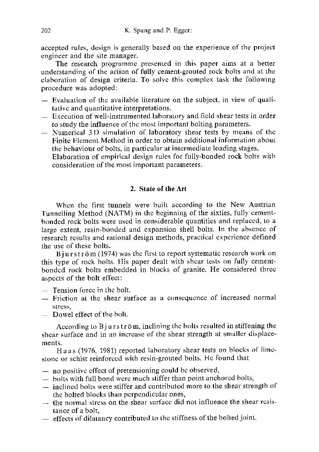
accepted rules, design is generally based on the experience of the project engineer and the site manager.
The research programme presented in this paper aims at a better understanding of the action of fully cement-grouted rock bolts and at the elaboration of design criteria. To solve this complex task the following procedure was adopted:
- - Evaluation of the available literature on the subject, in view of quali- tative and quantitative interpretations.
-- Execution of well-instrumented laboratory and field shear tests in order to study the influence of the most important bolting parameters.
- - Numerical 3 D simulation of laboratory shear tests by means of the Finite Element Method in order to obtain additional information about the behaviour of bolts, in particular at intermediate loading stages.
-- Elaboration of empirical design rules for fully-bonded rock bolts with consideration of the most important parameters.
2 . S t a t e o f t h e A r t
When the first tunnels were built according to the New Austrian Tunnelling Method (NATM) in the beginning of the sixties, fully cement- bonded rock bolts were used in considerable quantities and replaced, to a large extent, resin-bonded and expansion shell bolts. In the absence of research results and rational design methods, practical experience defined the use of these bolts.
Bj u r s t r ~ m (1974) was the first to report systematic research work on this type of rock bolts. His paper dealt with shear tests on fully cement- bonded rock bolts embedded in blocks of granite. He considered three aspects of the bolt effect:
-- Tension force in the bolt. - - Friction at the shear surface as a consequence of increased normal
stress, -- Dowel effect of the bolt.
According to Bj u r s t r 6 m, inclining the bolts resulted in stiffening the shear surface and in an increase of the shear strength at smaller displace- ments.
H a as (1976, 1981) reported laboratory shear tests on blocks of lime- stone or schist reinforced with resin-grouted bolts. He found that
-- no positive effect of pretensioning could be observed, -- bolts with full bond were much stiffer than point anchored bolts, - - inclined bolts were stiffer and contributed more to the shear strength of
the bolted blocks than perpendicular ones, - - the normal stress on the shear surface did not influence the shear resis-
tance of a bolt, -- effects of dilatancy contributed to the stiffness of the bolted joint.
Action of Fully-Grouted Bolts in Jointed Rock 203
A z u a r (1977) reported laboratory tests with resin-grouted bolts embedded in concrete. His main results are the following:
- - The maximum contribution of a rock bolt to the shear resistance of a joint is 60 to 80% of the ultimate tension load of the bolt in the case of perpendicular and about 90 % for inclined bolts.
- - The friction characteristics of the joint do not influence the contri- bution of the bolt.
- - Perpendicular bolts do not experience considerable tension stress. - - For a given shear displacement, dilatancy increases the resistance of the
bolted joint.
H i b i n o and M o t oj i m a (1981) described shear tests with ungrouted 2mm diameter bolts in concrete blocks. They considered bolts placed in 2 mm boreholes as fully-bonded and those in 40 mm holes as point anchored, and observed that:
- - For given displacements the shear resistance of fully-bonded bolts was considerably higher than that of point anchored ones.
- - The inclination of a bolt did not really increase its shear resistance. - - Pretensioning of the bolts reduced the shear displacements but did not
influence the shear resistance.
D i g h t (1982) examined the shear resistance of bolted joints using various materials such as gypsum, basalt and steel. He mainly found that:
- - The bolts were loaded by a combination of shear and tension stresses. - - The normal stress acting on the joint had no influence on the shear
resistance. - - Joints with inclined bolts were stiffer than those with perpendicular
o n e s .
- - The influence of dilatancy was similar to that of a bolt inclination. - - The deformed length of the bolt was related to the deformability of the
rock. - - The dowel effect was defined as the difference between the shear resis-
tance of a fully bounded and that of a point anchored bolt.
E g g e r and F e r n a n d e z (1983) tested bolted samples of concrete blocks in a high capacity press. They found that:
- - The optimum angle of bolt inclination with respect to the joint was 30 to 60 ~ .
- - Bolts perpendicular to the shear plane furnished the lowest shear resis- tance.
-- Shear displacements at failure were minimal for bolt inclinations between 40 and 50 ~ .
S c h u b e r t (1984) reported shear tests on bolted concrete and lime- stone blocks. The main results of his research work are:
-- The deformability of the surrounding rock is important for the bolt reaction.
204 K. Spang and P. Egger:
-- Bolts embedded in harder rock require smaller displacements for attaining a given resistance than those in softer rock.
-- Soft steels improve the deformability of the bolted system in soft rock.
In conclusion, the present state of knowledge about fully-grouted rock bolts enables us to explain, in a qualitative way, the bolting effect at failure and the influence of the main parameters. However, quantitative knowledge is still incomplete, as is the understanding of the progressive action of fully grouted bolts during shear displacements. Therefore the objective of the research work described in this paper was to obtain more information about these points.
3. Mode of Action of Fully-Bonded Rock Bolts
3.1 Preliminary Remarks
Bolted joints can be subjected to two categories of movements, either to opening of the joint in a direction perpendicular to the plane or to shear displacements occurring in the plane. Generally, deformations in jointed or stratified rock combine both types of movements because of the dilatancy effect of rough joints. In the research programme described hereafter, shear tests with rough joints were carried out, in addition to tests with smooth surfaces, to study the response of bolted blocks to combined tangential and normal displacements.
The first part of this chapter will relate the general observations concerning the mode of action of fully cement-bonded rock bolts made during the laboratory and field tests. The second part deals with the results of a 3 D finite element simulation of laboratory tests and emphasizes the progressive evolution of strains and stresses.
3.2 Principal Observations During the Shear Tests
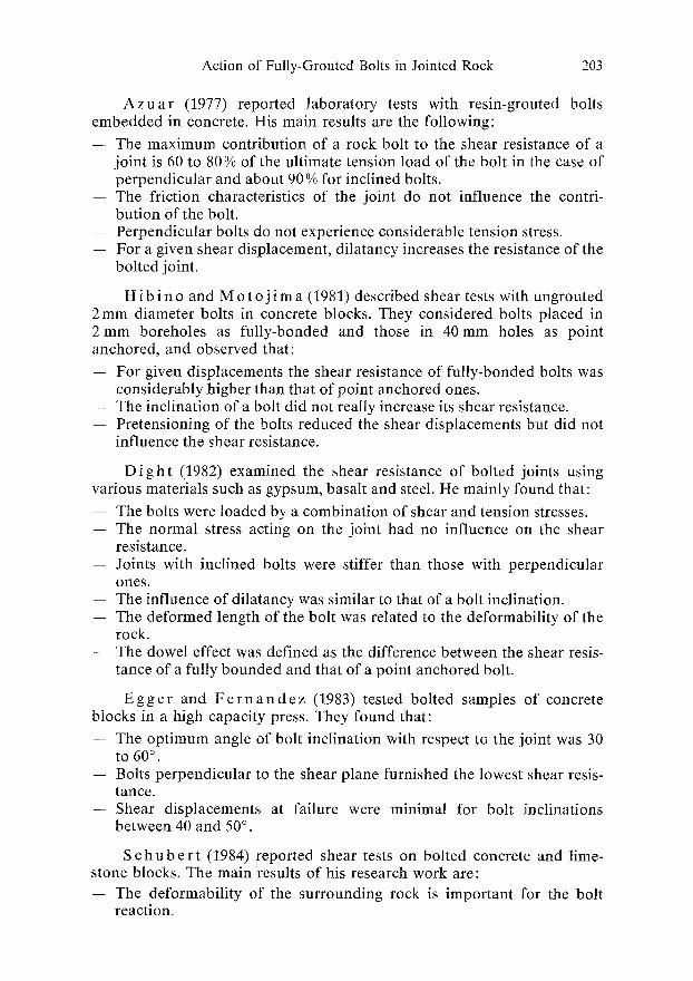
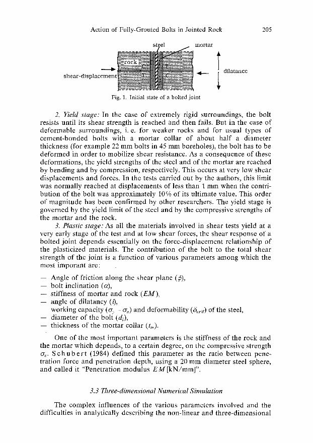
The initial state of the bolted joint is shown in Fig. 1, and, as shear displacements are imposed, three principal stages of behaviour can be distinguished:
I. Elastic stage: After overcoming the cohesion or adhesive strength of the joint, the blocks begin to slide with respect to each other. The shear resistance of the bolted joint consists of its proper shear strength r = o-n" tan ~ and of the contribution of the bolt. This latter is a result of the elastic responses of the bolt, the mortar and the rock and depends, therefore, on the Young's moduli of these materials as well as on the dimensions of the bolt and the mortar cylinder. The stresses in the three materials are compressive on the side behind the bolt (C in Fig. 1) and tensile on its front side (Tin Fig. 1). The tension stresses in the mortar and the rock will soon disappear because of the very low adhesive strength between steel and mortar giving rise to a gap on the tension side.
Action of Fully-Grouted Bolts in Jointed Rock 205
steel mortar
shear- d i s p l a e e m e n t ~ a i ~ i !]
Fig. 1. Initial state of a bolted joint
T dilatance
2. Yield stage: In the case of extremely rigid surroundings, the bolt resists until its shear strength is reached and then fails. But in the case of deformable surroundings, i.e. for weaker rocks and for usual types of cement-bonded bolts with a mortar collar of about half a diameter thickness (for example 22 mm bolts in 45 mm boreholes), the bolt has to be deformed in order to mobilize shear resistance. As a consequence of these deformations, the yield strengths of the steel and of the mortar are reached by bending and by compression, respectively. This occurs at very low shear displacements and forces. In the tests carried out by the authors, this limit was normally reached at displacements of less than 1 mm when the contri- bution of the bolt was approximately 10% of its ultimate value. This order of magnitude has been confirmed by other researchers. The yield stage is governed by the yield limit of the steel and by the compressive strengths of the mortar and the rock.
3. Plastic stage: As all the materials involved in shear tests yield at a very early stage of the test and at low shear forces, the shear response of a bolted joint depends essentially on the force-displacement relationship of the plasticized materials. The contribution of the bolt to the total shear strength of the joint is a function of various parameters among which the most imporant are:
-- Angle of friction along the shear plane (1b), - - bolt inclination (~), - - stiffness of mortar and rock (EM), - - angle of dilatancy (0, - - working capacity (o-y - o-,) and deformability (~nif) of the steel, -- diameter of the bolt (db), -- thickness of the mortar collar (tin).
One of the most important parameters is the stiffness of the rock and the mortar which depends, to a certain degree, on the compressive strength ~ . S c h u b e r t (1984) defined this parameter as the ratio between pene- tration force and penetration depth, using a 20 mm diameter steel sphere, and called it "Penetration modulus E M [kN/mm]".
3.3 Three-dimensional Numerical Simulation
The complex influences of the various parameters involved and the difficulties in analytically describing the non-linear and three-dimensional
206 K. Spang and P. Egger:
response of the plasticized materials are prohibitive for analytical solutions of the shear-bolt problem.
In the previous section, the observations made during the laboratory and field tests are described qualitatively and the principal remarks and classifications are given. For the quantitative description of the various phenomena occurring during a shear test on bolted rock blocks, a numerical 3 D simulation using the Finite Element Method was carried out.
Description of the Code
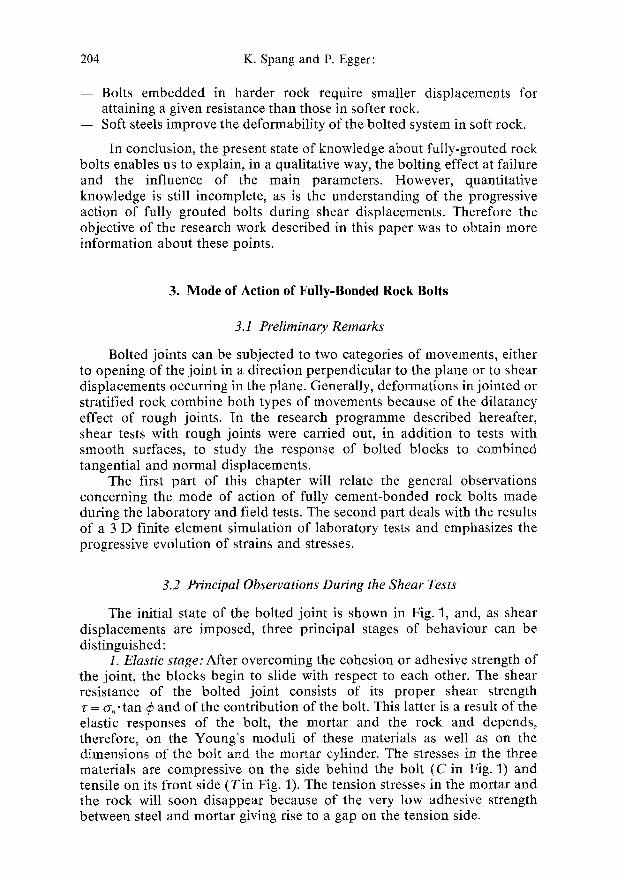
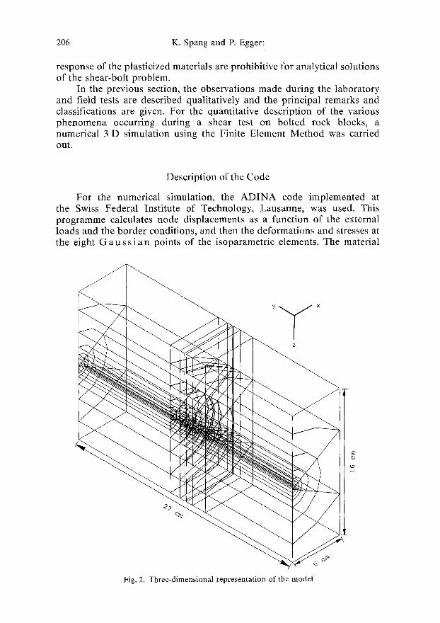
For the numerical simulation, the A D I N A code implemented at the Swiss Federal Institute of Technology, Lausanne, was used. This programme calculates node displacements as a function of the external loads and the border conditions, and then the deformations and stresses at the eight G au s s Jan points of the isoparametric elements. The material
Fig. 2. Three-dimensional representation of the model
~3
Action of Fully-Grouted Bolts in Jointed Rock 207
properties of the ideally elastic elements are defined by the modulus of elasticity and Poisson's ratio. To describe the behaviour of the elastic- plastic materials, the D r u c k e r- P r a g e r and v o n M i s e s failure criteria were used.
Description of the Model
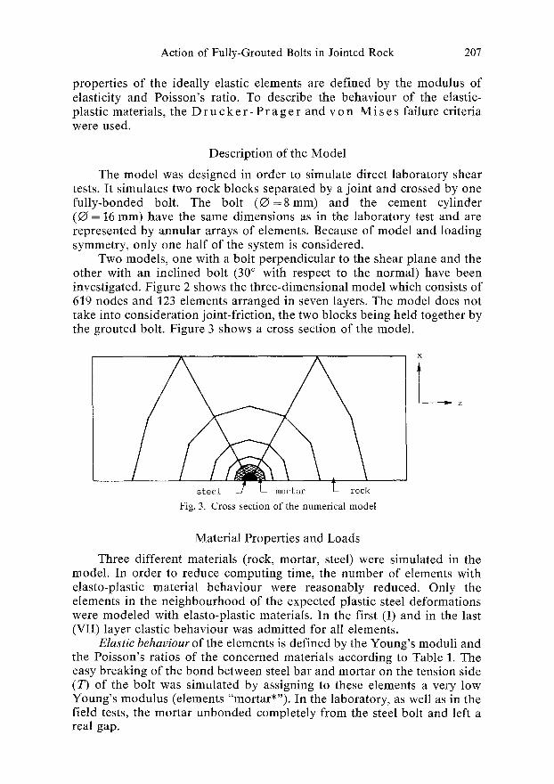
The model was designed in order to simulate direct laboratory shear tests. It simulates two rock blocks separated by a joint and crossed by one fully-bonded bolt. The bolt ( O = 8 m m ) and the cement cylinder (Q = 16 ram) have the same dimensions as in the laboratory test and are represented by annular arrays of elements. Because of model and loading symmetry, only one half of the system is considered.
Two models, one with a bolt perpendicular to the shear plane and the other with an inclined bolt (30 ~ with respect to the normal) have been investigated. Figure 2 shows the three-dimensional model which consists of 619 nodes and 123 elements arranged in seven layers. The model does not take into consideration joint-friction, the two blocks being held together by the grouted bolt. Figure 3 shows a cross section of the model.
steel ~ L mortar T_ rock
Fig. 3. Cross section of the numerical model
Z
Material Properties and Loads
Three different materials (rock, mortar, steel) were simulated in the model. In order to reduce computing time, the number of elements with elasto-ptastic material behaviour were reasonably reduced. Only the elements in the neighbourhood of the expected plastic steel deformations were modeled with elasto-plastic materials. In the first (I) and in the last (VII) layer elastic behaviour was admitted for all elements.
Elastic behauiour of the elements is defined by the Young's moduli and the Poisson's ratios o f the concerned materials according to Table 1. The easy breaking of the bond between steel bar and mortar on the tension side (7) of the bolt was simulated by assigning to these elements a very low Young's modulus (elements "mortar*"). In the laboratory, as well as in the field tests, the mortar unbonded completely from the steel bolt and left a real gap.
208 K. Spang and P. Egger:
Table 1. Elastic Material Properties
Material Young's modulus Poisson's ratio v [MPa]
Steel 210 000 0.3 M o l a r 8 000 0.2 Rock 20 000 0.2 Mogar* 20 0.2
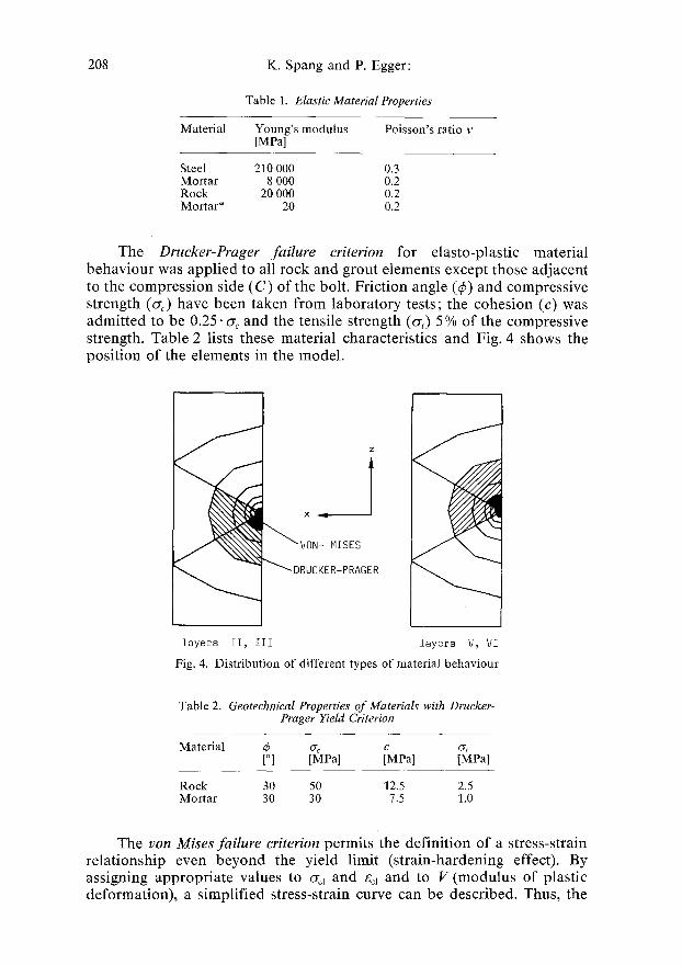
The Drucker-Prager failure criterion for elasto-plastic material behaviour was applied to all rock and grout elements except those adjacent to the compression side (C) of the bolt. Friction angle (~) and compressive strength (~c) have been taken from laboratory tests; the cohesion (c) was admitted to be 0.25. or<, and the tensile strength (0,) 5 % of the compressive strength. Table 2 lists these material characteristics and Fig. 4 shows the position of the elements in the model.
~ V~N; MISES
RUCKER-PRAGER
layers II, III iayers V, VI
Fig. 4. Distribution of different types of material behaviour
Table 2. Geotechnical Properties of Materials with Drucker- Prager YieM Criterion
Material ~ ~ c c5 [~ [MPa] [MPa] [MPa]
Rock 30 50 12.5 2.5 Mortar 30 30 7.5 1.0
The yon Mises failure criterion permits the definition of a stress-strain relationship even beyond the yield limit (strain-hardening effect). By assigning appropriate values to O-e~ and gd and to V (modulus of plastic deformation)~ a simplified stress-strain curve can be described. Thus, the
Action of Fully-Grouted Bolts in Jointed Rock 209
resistance of steel, rock and mortar to deformation in the plastic stage, which represents the main part of the bolt reaction, can be simulated by the programme. For the material characteristics see Table 3 and for the situ- ation of the elements in the model see Fig. 4.
Tabelle 3. Geotechnical Properties o f Materials with yon Mises Failure Criterion
Material ~Tej ~el ~pl V1 ~. V2 [MPal [ - 1 [MPa] [MPal [MPa] [MPa]
Steel 630 0.0030 675 650 710 130 M o l a r 30 0.0038 75 300 210 300 Rock 40 0.0020 90 375 230 375
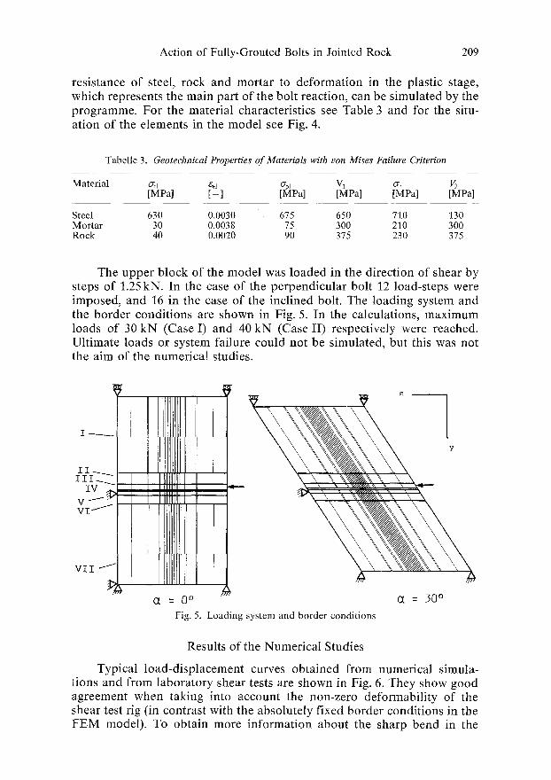
The upper block of the model was loaded in the direction of shear by steps of 1.25 kN. In the case of the perpendicular bolt 12 load-steps were imposed, and 16 in the case of the inclined bolt. The loading system and the border conditions are shown in Fig. 5. In the calculations, maximum loads of 30 kN (Case I) and 40 kN (Case II) respectively were reached. Ultimate loads or system failure could not be simulated, but this was not the aim of the numerical studies.
II Illfllil[li[i IV , ,t,,m~
v ----- iii iii)i]iiiiiili
V I I
i ~ = 0 ~
Fig. 5. Loading system and border conditions
= 30 ~
Results of the Numerical Studies
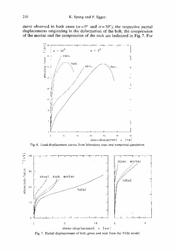
Typical load-displacement curves obtained from numerical simula- tions and from laboratory shear tests are shown in Fig. 6. They show good agreement when taking into account the non-zero deformability of the shear test rig (in contrast with the absolutely fixed border conditions in the FEM model). To obtain more information about the sharp bend in the
210 K. Spang and P. Egger:
curve observed in both cases ( ~ = 0 ~ and c~=30~ the respective partial displacements originating in the deformation of the bolt, the compression of the mortar and the compression of the rock are indicated in Fig. 7. For
i--
3S
2s
2O
IS
IQ
5
= 300 ~ = 0 ~
/ t a le . /
/ / .,"---',, test
,' ", calc. / ~ tes t < ' / / \ !11 t
/ /
1
5 lo is 20 25 30
slqear-displacement s [mm ]
Fig. 6. Load-displacement curves from laboratory tests and numerical simulation
Z
o
q_
& c-
c- co
qO
30
20
10
I I - - I I r I I I I I I
steel// ,',r~ mortar ~
t o t a l
i 1 1 1 1 1 i__ 1 ~ 1 1
5 10
shear-displacement s [ m m ]
I I I I
steel mortar
Fig. 7. Partial displacements of bolt, grout and rock from the FEM model
Act ion o f Fu l l y -Grouted Bolts in Jo inted R o c k 211
c~ = 0 ~ it is obvious that the mentioned bend is a result of the fracture of the mortar and of the rock, which enables the deformation of the bolt. In the case of the inclined bolt, the displacements due to compression/fracture of the mortar and to (small) deformations of the bolt can also be observed, but there are very few displacements and no bend in the load-deformation curve of the rock. The latter observation means that the inclined bolt mobi- lizes more load with less deformation; the compression of mortar and rock is lower than in the case of a perpendicular bolt. In the case shown, the rock seemed not even to have been broken.
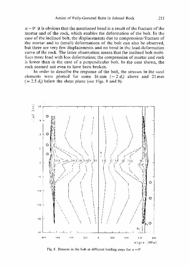
In order to describe the response of the bolt, the stresses in the steel elements were plotted for some 16ram ( = 2 db) above and 21ram ( ~ 2.5 db) below the shear plane (see Figs. 8 and 9).
E 20 E
(8
I S
tO
5
-S
- 1 0
- 1 5
- 2 0
- 2 5
~ l/i[ / /
Ili ,, < @ ', \ \
rll~ L J ~ . " / 5/Jz.~
. / / " / /
!" I I
'\ \ , \ ' \ \\ \
', \ \ \\ \ /
/ ~ - - I I I I I I
800 600 400 200 0
", \ \
j /" /
', ~
; "1 @ f
i / o / z
1 I1' /
/ i
i/ / [ s / , / ,G
T I I
200 gO0 800 800
sigma [IIPa]
Fig. 8. Stresses in the bolt at different loading steps for ~ = 0 ~
212 K. Spang and P. Egger:
E 2O
~o
I0
-5
-10
-,5 i
-20 L
800 BOO qO0 200 0 2 ]0 400 EO0
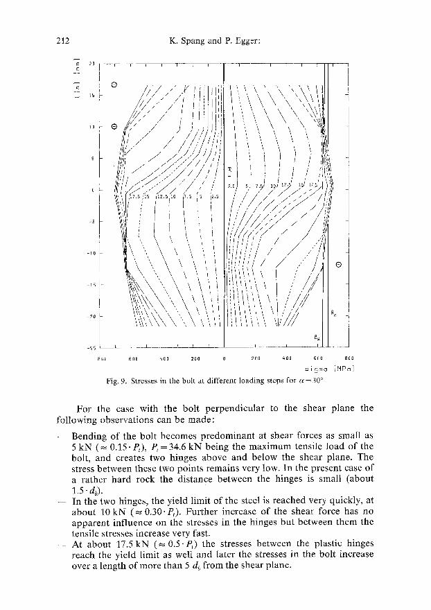
zisma Fig. 9. Stresses in the bolt at d i f ferent load ing s teps for G = 30 ~
800
[MPo]
For the case with the bolt perpendicular to the shear plane the following observations can be made:
-- Bending of the bolt becomes predominant at shear forces as small as 5 kN (~ 0.15. P~), P~ = 34.6 kN being the maximum tensile load of the bolt, and creates two hinges above and below the shear plane. The stress between these two points remains very low. In the present case of a rather hard rock the distance between the hinges is small (about 1.5" &).
- - In the two hinges, the yield limit of the steel is reached very quickly, at about 10 kN ( ~ 0.30- P~). Further increase of the shear force has no apparent influence on the stresses in the hinges but between them the tensile stresses increase very fast.
- - At about 17.5 kN (~ 0.5-P~) the stresses between the plastic hinges reach the yield limit as well and later the stresses in the bolt increase over a length of more than 5 db from the shear plane.
Action of Fully-Grouted Bolts in Jointed Rock 213
-- As the stress level is approximately constant in the zone between the two hinges, the exact location of failure cannot be predicted. Failure may occur by bending in one of the plastic hinges or by combined shear and tension near the shear surface. Test results showed the occurrence of both failure types for tests under apparently the same conditions, but ultimate loads and displacements at failure were nearly identical.
- - Considerable shear resistance of the bolt is not possible without bending and yielding of the steel.
In the case of the inclined bolt (30 ~ ) the response of the system is similar, with the exception of the following particular features:
-- Bending of the bolt at small shear forces is clearly less than that of the perpendicular bolt and the compressive stresses are lower.
-- The yield limit of the steel is not reached before a shear load of 17.5 kN (-~ 0.5 "P0 but simultaneously at the shear surface and below it.
-- An increasing shear load involves an increase of stresses, particularly near the shear surface.
-- The ultimate load of the bolt is reached first near the shear surface. In the laboratory tests the great majority of the inclined bolts failed in tension near the shear surface, no failure occurring at the bending points. It is concluded that the major stress in the inclined bolt is tensile.
- - In the case of inclined bolts, considerable shear resistance can be mobi- lized without any bending of the bolts.
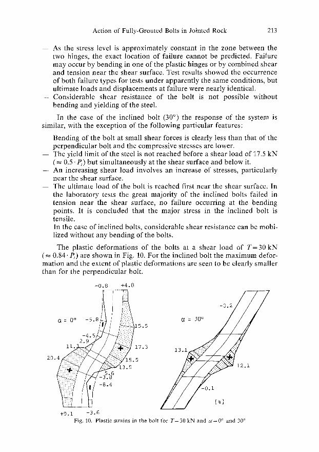
The plastic deformations of the bolts at a shear load of T = 3 0 kN ( ~ 0.84. P,) are shown in Fig. 10. For the inclined bolt the maximum defor- mation and the extent of plastic deformations are seen to be clearly smaller than for the perpendicular bolt.
-0.8 +4.8
- 0 . 2
C~ : 0 ~ -5.8 ~ / / i
~ 1 7 . 3 1 3 . ~ 20.4 y15.5 / 12.1
jjjii -: ~ -8.4 / ~ / / - 0 . 1 [ ~ ]
+ 9 . 1 - 3 . 6
F ig . 10. P l a s t i c s t r a i n s in t h e b o l t f o r T = 3 0 k N a n d c ~ = 0 ~ a n d 30 ~
214
E E
c0
0 T =
-I0
-20
-30
K. Spang and P. Egger:
I I l
25 20 15 i0
. \ -<"'-" '\\'! \., \
X~
=0 ~
12.S 25
. . . . \ /
i\ '~ '1
I
J
I
5 2 . 5 1
\ ' , , /~
i\",1-1 \'x ill
i
O~ =301
-200 -150 -100 -50 0 -50 0
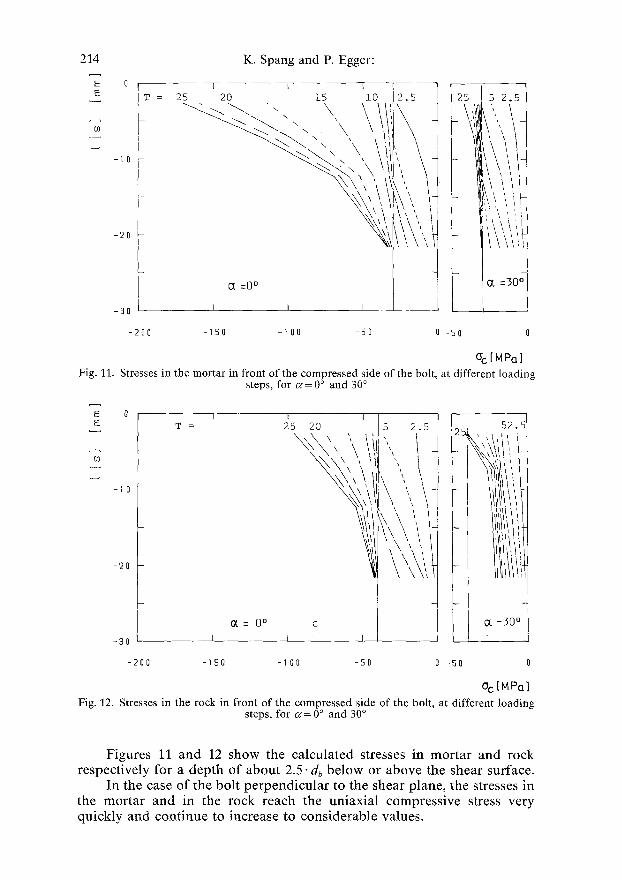
O'c [ MPa ] Fig. 11. Stresses in the mortar in front of the compressed side of the bolt, at different loading
steps, for er = 0 ~ and 30 ~
o [ i l J I I T = 2S 2O I~
L �89 \ii',, 5
-200 -150 -I00 -50 0 'fi0 0
Oc [MPa] Fig. 12. Stresses in the rock in front of the compressed side of the bolt, at different loading
steps, for ~ = 0 ~ and 30 ~
F igures 11 and 12 s h o w the c a l c u l a t e d s tresses in m o r t a r and r o c k r e s p e c t i v e l y for a d e p t h o f a b o u t 2 .5- db b e l o w or a b o v e the shear surface .
In the case o f the bo l t p e r p e n d i c u l a r to the shear p lane , the s tresses in the m o r t a r and in the r o c k reach the u n i a x i a l c o m p r e s s i v e stress very q u i c k l y and c o n t i n u e to i n c r e a s e to c o n s i d e r a b l e va lues .
Action of Fully-Grouted Bolts in Jointed Rock 215
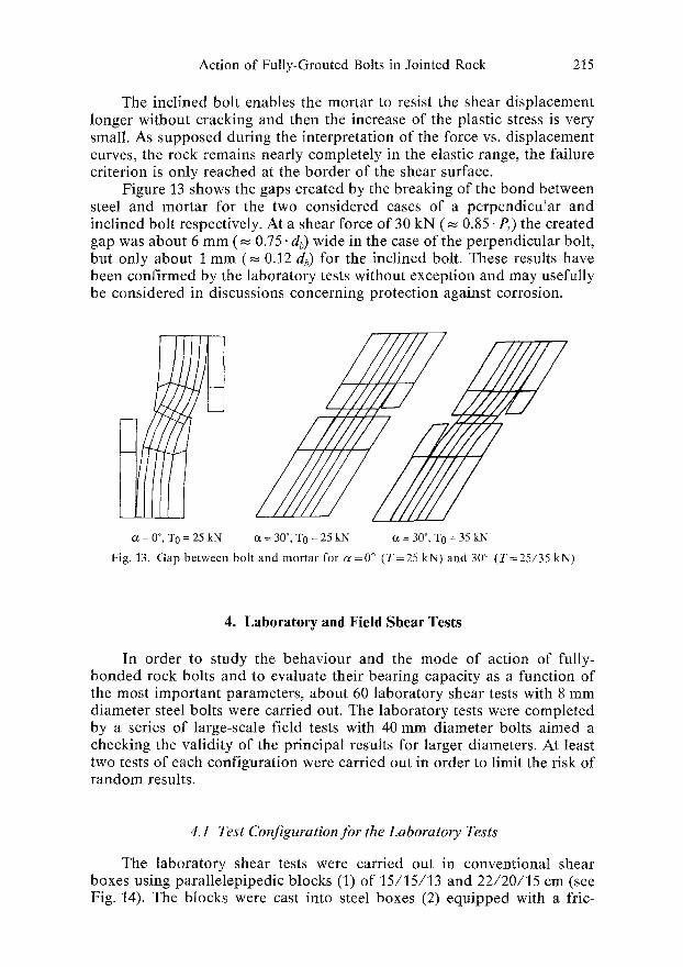
The inclined bolt enables the mortar to resist the shear displacement longer without cracking and then the increase of the plastic stress is very small. As supposed during the interpretation of the force vs. displacement curves, the rock remains nearly completely in the elastic range, the failure criterion is only reached at the border of the shear surface.
Figure 13 shows the gaps created by the breaking of the bond between steel and mortar for the two considered cases of a perpendicular and inclined bolt respectively. At a shear force of 30 kN ( ~ 0.85. P,) the created gap was about 6 mm ( ~ 0.75. db) wide in the case of the perpendicular bolt, but only about 1 mm ( ~ 0.12 db) for the inclined bolt. These results have been confirmed by the laboratory tests without exception and may usefully be considered in discussions concerning protection against corrosion.
c~ = 0 ~ TO = 25 kN
/////// 4???2
o~ = 30 ~ TO = 25 kN ~ = 30 ~ T0 = 35 kN
F ig . 13. G a p b e t w e e n b o l t a n d m o r t a r f o r c o = 0 ~ ( T = 2 5 k N ) a n d 30 ~ ( T = 2 5 / 3 5 k N )
4. Laboratory and Field Shear Tests
In order to study the behaviour and the mode of action of fully- bonded rock bolts and to evaluate their bearing capacity as a function of the most important parameters, about 60 laboratory shear tests with 8 mm diameter steel bolts were carried out. The laboratory tests were completed by a series of large-scale field tests with 40 mm diameter bolts aimed a checking the validity of the principal results for larger diameters. At least two tests of each configuration were carried out in order to limit the risk of random results.
4.1 Test Configuration for the Laboratory Tests
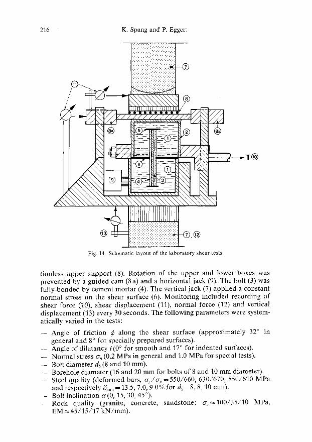
The laboratory shear tests were carried out in conventional shear boxes using parallelepipedic blocks (1) of 15/15/13 and 22/20/15 cm (see Fig. 14). The blocks were cast into steel boxes (2) equipped with a fric-
226 K. Spang and P. Egger:
@
Fig. 14. Schematic layout of the laboratory shear tests
tionless upper support (8). Rotation of the upper and lower boxes was prevented by a guided cam (8 a) and a horizontal jack (9). The bolt (3) was fully-bonded by cement mortar (4). The vertical jack (7) applied a constant normal stress on the shear surface (6). Monitoring included recording of shear force (10), shear displacement (11), normal force (12) and vertical displacement (13) every 30 seconds. The following parameters were system- atically varied in the tests:
-- Angle of friction ~b along the shear surface (approximately 32 ~ in general and 8 ~ for specially prepared surfaces).
-- Angle of dilatancy i(0 ~ for smooth and 17 ~ for indented surfaces). - - Normal stress o-~, (0.2 MPa in general and 1.0 MPa for special tests). - - Bolt diameter db (8 and 10 mm). - - Borehole diameter (16 and 20 mm for bolts of 8 and 10 mm diameter). -- Steel quality (deformed bars, C~y/~y, = 550/660, 630/670, 550/610 MPa
and respectively 6~nif = 13.5, 7.0, 9.0% for db= 8, 8, 10 mm). - - Bolt inclination ~(0, 15, 30, 45~ - - R o c k quality (granite, concrete, sandstone; o-c~100/35/10 MPa,
EM ~ 45/15/17 kN/mm).
Action of Fully-Grouted Bolts in Jointed Rock 217
For all tests the bolt was grouted over its total length with a pure cement grout (o% ~ 35 MPa, EM ~. 9.5 kN/mm).
4.2 Test Configuration for the Field Tests
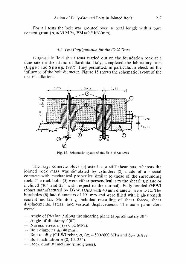
Large-scale field shear tests carried out on the foundation rock at a dam site on the island of Sardinia, Italy, completed the laboratory tests (E g g e r and S p a n g, 1987). They permitted, in particular, a check on the influence of the bolt diameter. Figure 15 shows the schematic layout of the test installations.
,_ 0.75 -I- 1.20 m �9 0.75
i iiiiiiiiiiiiiiiiiiiiiiii iiiiiiiiiiiiiiiiYiiii i' iYiiiiiiiiiiiii !iiii !iiii iii iiiili i ! .20
Fig. 15. Schematic layout of the field shear tests
The large concrete block (3) acted as a stiff shear box, whereas the jointed rock mass was simulated by cylinders (2) made of a special concrete with mechanical properties similar to those of the surrounding rock. The rock bolts (5) were either perpendicular to the shearing plane or inclined (10 ~ and 25 ~ with respect to the normal). Fully-bonded GEWI rebars manufactured by DYWIDAG with 40 mm diameter were used. The boreholes (6) had diameters of 101 mm and were filled with high-strength cement mortar. Monitoring included recording of shear forces, shear displacements, lateral and vertical displacements. The main parameters were:
- - Angle of friction ~ along the shearing plane (approximately 30~ -- Angle of dilatancy i (0~ -- Normal stress ~, ( ~ 0.02 MPa). - - Bolt diameter db (40 ram). -- Bolt quality (GEWI rebar, o-;./ou = 500/600 MPa and 6s = 16.8 %). - - Bolt inclination o~ (0, 10, 25~ -- Rock quality (metamorphic gneiss).
218 K. Spang and P. Egger:
4.3 Results of Laboratory and Field Tests
In order to enable comparisons among test results obtained with different bolt diameters or steel qualities, the following dimensionless values are defined:
f (T )=(T-TN) /P , and f(s)=s/db,
where T = shear force obtained in the test, TN = shear strength of the natural unbolted joint, P, = maximum tension load of the bolt and s = shear displacement obtained in the test.
In all tests, the bolts were grouted with cement mortar in boreholes of about twice the bolt diameter. For other conditions, as for example resin mortars or very small annular spaces around the bolt, the results may be different and cannot be used without being checked by additional tests.
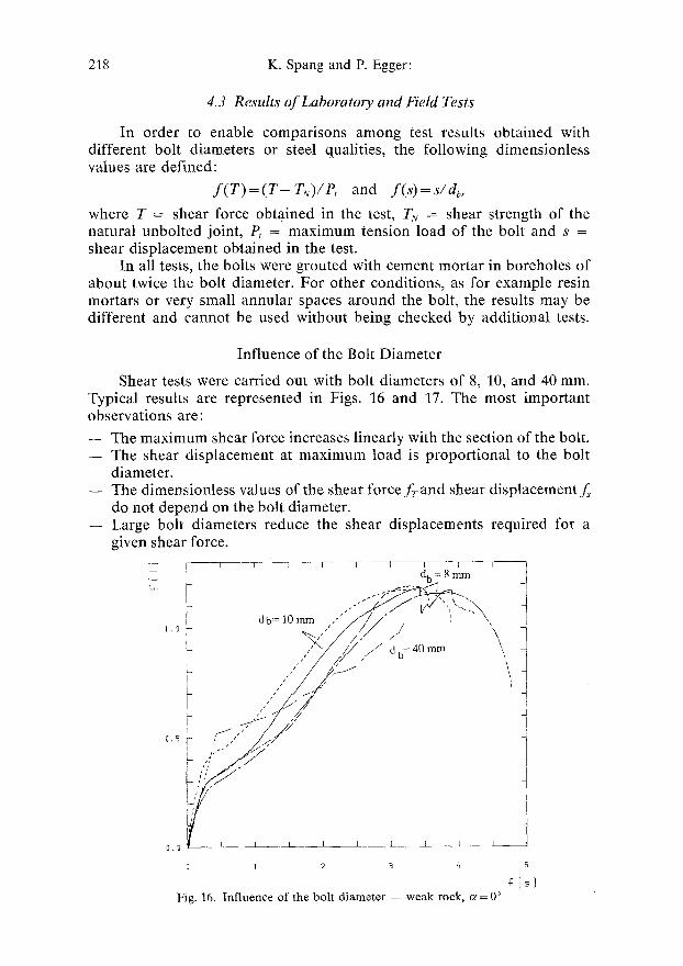
Influence of the Bolt Diameter
Shear tests were carried out with bolt diameters of 8, 10, and 40 mm. Typical results are represented in Figs. 16 and 17. The most important observations are:
-- The maximum shear force increases linearly with the section of the bolt. -- The shear displacement at maximum load is proportional to the bolt
diameter. -- The dimensionless values of the shear force f r and shear displacement s
do not depend on the bolt diameter. -- Large bolt diameters reduce the shear displacements required for a
given shear force.
I db= 10 mm , " " / ' ~ / / v ' ~ " ,
~- " U / ~ ~ db=40mm \
E " /
0 1 2 3 q 5
Fig. 16. Influence of the bolt diameter -- weak rock, o~ = 0 ~
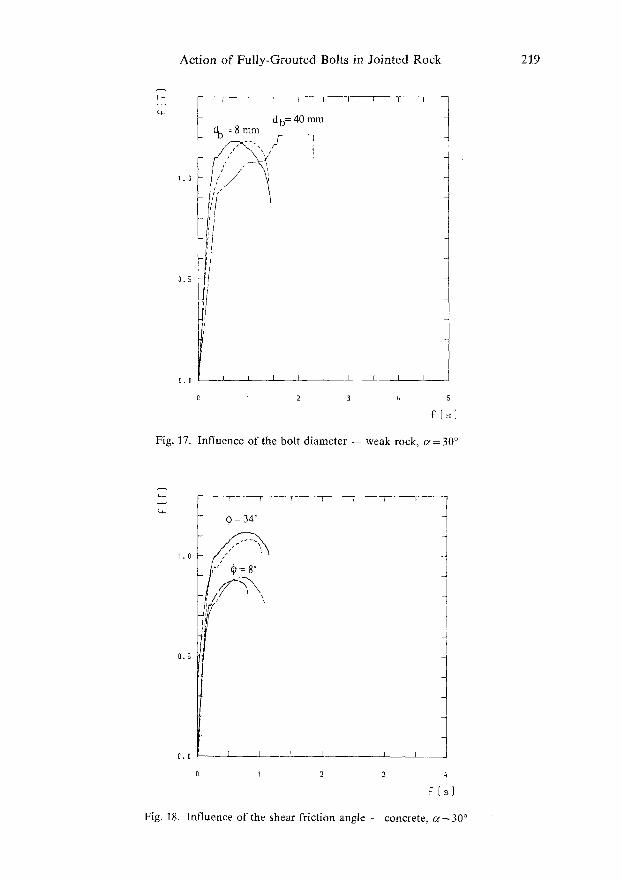
Action of Fully-Grouted Bolts in Jointed Rock 219
t db= 40 mm
=,:=7'.. =,
l I - - S ' - ~ I
0 . 5
0 , 0 I t l I _ _ ~ I I I - J
0 1 2 3 t, 5
~ ' ( s ]
Fig. 17. Influence of the bolt diameter - - weak rock, cc=30 ~
c,_
1 . 0
0 . 5
I - - T
0 = 3 4 ~
7"
O. 0 E ~ - J L _ _ I I I
2 3 t~
F ( s )
Fig. 18, Influence of the shear friction angle -- concrete, cr 30 ~
220 K. Spang and P. Egger:
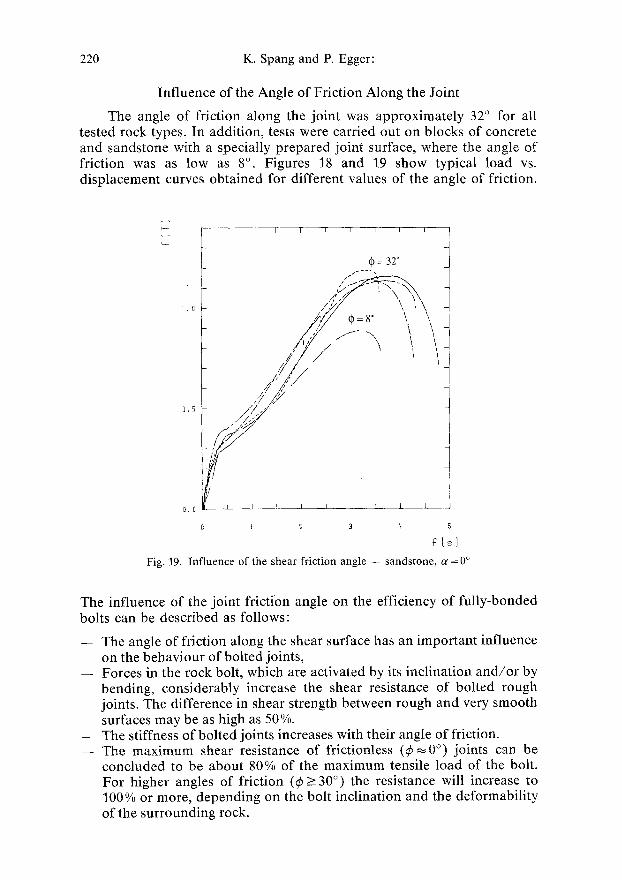
Influence of the Angle of Friction Along the Joint
The angle of friction along the joint was approximately 32 ~ for all tested rock types. In addition, tests were carried out on blocks of concrete and sandstone with a specially prepared joint surface, where the angle of friction was as low as 8 ~ . Figures 18 and 19 show typical load vs. displacement curves obtained for different values of the angle of friction.
T - - F I I I I - - - - T ~ I I
t / /
(\1 i. o f
/ / / / J / / / '
, , / / 7 ;/ 0 , f i ~ / /
I
O.O I__ I _I 1 i. k I ~ - - I
El I 2 3 q 5
~'[sl
Fig . 19. I n f l u e n c e o f t h e s h e a r f r i c t i o n a n g l e - - s a n d s t o n e , c~ = 0 ~
The influence of the joint friction angle on the efficiency of fully-bonded bolts can be described as follows:
- - The angle of friction along the shear surface has an important influence on the behaviour of bolted joints,
- - Forces in the rock bolt, which are activated by its inclination and/or by bending, considerably increase the shear resistance of bolted rough joints. The difference in shear strength between rough and very smooth surfaces may be as high as 50 %.
- - The stiffness of bolted joints increases with their angle of friction. - - The maximum shear resistance of frictionless (~b ~ 0 ~ joints can be
concluded to be about 80% of the maximum tensile load of the bolt. For higher angles of friction (~b >30 ~ the resistance will increase to 100 % or more, depending on the bolt inclination and the deformability of the surrounding rock.
Action of Fully-Grouted Bolts in Jointed Rock 221
-- The displacement at maximum shear load seems not to be influenced by the angle of friction, but the stiffness of the bolted system increases with the joint friction.
- - For approximative calculations, the influence of the joint friction on the shear resistance of the bolted joint may be related to the maximum tensile load of the bolt by the dimensionless value
mR = (0.85 + 0.45" tan ~).
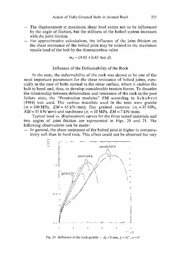
Influence of the Deformability of the Rock
In the tests, the deformability of the rock was shown to be one of the most important parameters for the shear resistance of bolted joints, espe- cially in the case of bolts normal to the shear surface, where it enables the bolt to bend and, thus, to develop considerable tension forces. To describe the relationship between deformation and resistance of the rock in the post failure state, the "Penetration modulus" EM according to S c h u b e r t (1984) was used. The various materials used in the tests were granite (o-c~-.]00MPa, EM~.45kN/mm), fine grained concrete ( G ~ . 3 5 M P a , E M ~ 15 k N / m m ) and sandstone (G ~ 10 MPa, EM~ 7 kN/mm).
Typical load vs. displacement curves for the three tested materials and two angles of joint friction are represented in Figs. 20 and 21. The following observations can be made: -- In general, the shear resistance of the bolted joint is higher in compara-
tively soft than in hard rock. This effect could not be observed for very
F--- I r I-- I - - T ~ t ~ - I - - ~ -
~- sandstone
concrete , / ~ & / / \
,.a / F \ \ , / / : ..J/ I X , " \
~ca~i te."',//~ 9 \.
; 2// , o.5 I / ~ ~1/ ."/" 1
o . o ~ r _ ~ ~ ~ , L
0 2 3 4 5
Fig, 20. I n f l u e n c e o f the r o c k q u a l i t y - - d8 = 8 m m , ~ = 32 ~ ~z = 0 ~
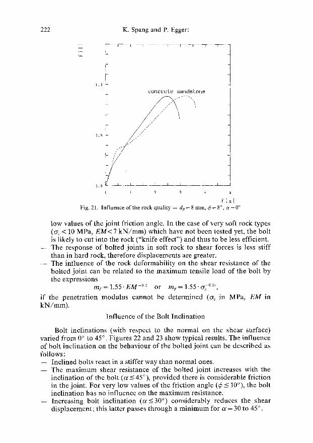
222 K. Spang and P. Egger:
1 . 0 i
i
I I ~ - - I I I I 1 I
c o n c r e t e sandsLone
1 ,
0"5 I , '"
0 1 2 3 q 5
Fig . 21. I n f l u e n c e o f t h e r o c k q u a l i t y - - d~ = 8 r a m , r = 8~ c~ = 0 ~
low values of the joint friction angle. In the case of very soft rock types ( ~ < 10 MPa, E M < 7 kN/mm) which have not been tested yet, the bolt is likely to cut into the rock ("knife effect") and thus to be less efficient.
-- The response of bolted joints in soft rock to shear forces is less stiff than in hard rock, therefore displacements are greater.
- - The influence of the rock deformability on the shear resistance of the bolted joint can be related to the maximum tensile load of the bolt by the expressions
m~ = 1.55. E M -~ or m F = 1 . 5 5 " ~c ~
if the penetration modulus cannot be determined (o-c in MPa, E M in kN/mm).
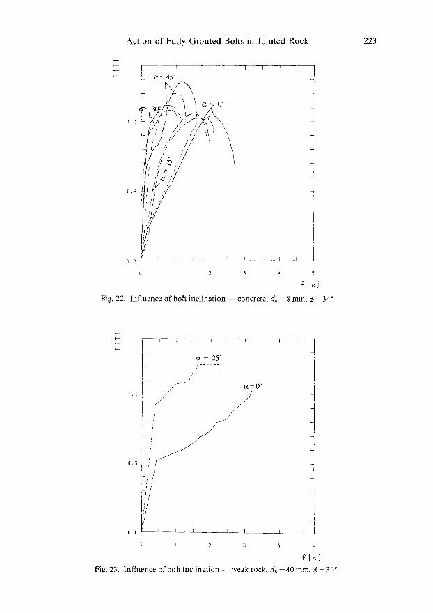
Influence of the Bolt Inclination
Bolt inclinations (with respect to the normal on the shear surface) varied from 0 ~ to 45 ~ Figures 22 and 23 show typical results. The influence of bolt inclination on the behaviour of the bolted joint can be described as follows:
- - Inclined bolts react in a stiffer way than normal ones. - - The maximum shear resistance of the bolted joint increases with the
inclination of the bolt (c~ <_ 45~ provided there is considerable friction in the joint. For very low values of the friction angle (~b _< 10~ the bolt inclination has no influence on the maximum resistance.
- - Increasing bolt inclination (~___30 ~ considerably reduces the shear displacement; this latter passes through a minimum for c~ = 30 to 45 ~ .
Action of Fully-Grouted Bolts in Jointed Rock 223
T i J I - - - Y
L
1 . 0
0 . 5
r 1 F i ~
o ~ = 4 5 ~
0 I 2 3 q 5
s
Fig. 22. I n f l u e n c e o f b o l t i n c l i n a t i o n - - c o n c r e t e , d8 = 8 ram, ~ = 3 4 ~
r
] I I ] T T I I T - -
o ~ = 2 5 ~ ; . . . . . ;
t
o ~ = 0 ~
1 . 0
0 . 5
0,0 L
0 1 2 3
I
4 5
Fig. 23. I n f l u e n c e o f b o l t i n c l i n a t i o n - - w e a k r o c k , de = 4 0 m m , q~ = 3 0 ~
224 K. Spang and P. Egger:
-- The effect of the inclination depends on the deformability of the surrounding rock.
-- The combined influence of bolt inclination and rock deformability on the maximum shear resistance can be related to the maximum tensile load of the bolt by the dimensionless expressions:
A TA • 0.007. E M l's. sin 2 c~ or A T A~- 0.007. ~.0v. sin 2 c~.
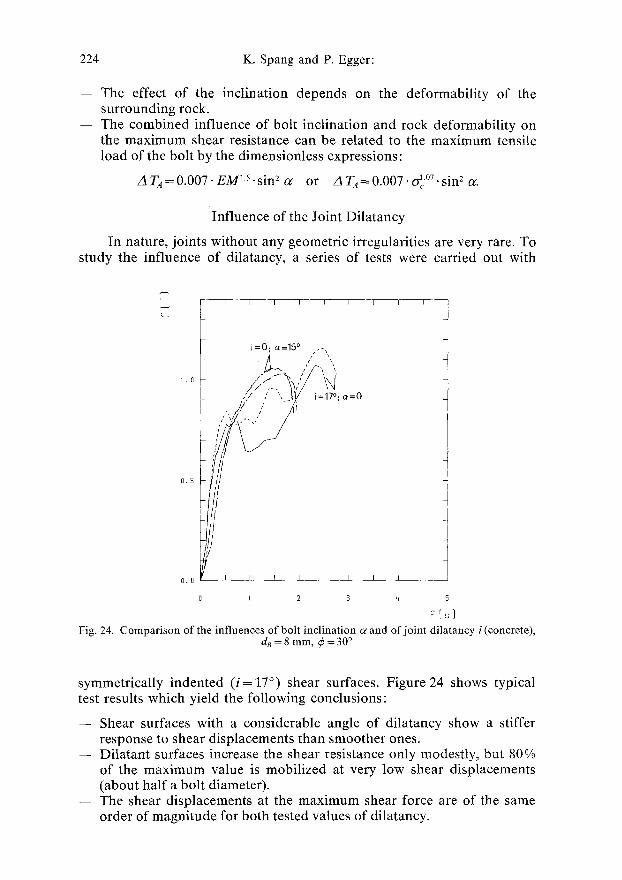
Influence of the Joint Dilatancy
In nature, joints without any geometric irregularities are very rare. To study the influence of dilatancy, a series of tests were carried out with
C*.
1 . O
0 . 5
0 . 0
I I I l - - I I - - I r I
= 0 . oz=15 ~ , ,- ,
.Y.."". _IV
I _ _ . ~ 1 L_ I _ I
O I 2 3
I I ~ _ _ ~
4 5
F[s] Fig. 24. C o m p a r i s o n o f the in f luences o f bolt inc l ina t ion c~ and of jo in t d i la tancy i (concrete),
d8 = 8 ram, ~ = 30 ~
symmetrically indented ( i=17 ~ shear surfaces. Figure 24 shows typical test results which yield the following conclusions:
- - Shear surfaces with a considerable angle of dilatancy show a stiffer response to shear displacements than smoother ones.
-- Ditatant surfaces increase the shear resistance only modestly, but 80% of the maximum value is mobilized at very low shear displacements (about half a bolt diameter).
- - The shear displacements at the maximum shear force are of the same order of magnitude for both tested values of dilatancy.
Action of Fully-Grouted Bolts in Jointed Rock 225
or
The influence of the angle of dilatancy on the maximum shear resis- tance of the bolt is comparable with that of the bolt inclination. Therefore the expression developed for the consideration of the bolt inclination can be extended to
A TA+~ = 0.007" EM T M sin 2 (or+ i)
A TA+G = 0.007" 4 .07 -sin z (c~ + i).
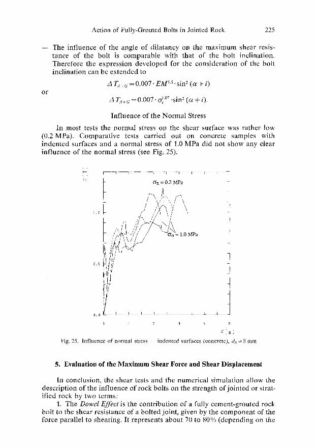
Influence of the Normal Stress
In most tests the normal stress on the shear surface was rather low (0.2 MPa). Comparative tests carried out on concrete samples with indented surfaces and a normal stress of 1.0 MPa did not show any clear influence of the normal stress (see Fig. 25).
t4~
1 . 0
0 . 5
{I.0
I r q - - , ;n=;.2M~ a q - - T ~ ~ !
p
t , / A ' ~ ' - ' 7 / ' / " (~n=l.0MPa
f
I I _ I ~ I. I t _ l .,J
; 2 3 q 5
?{s}
Fig. 25. Influence of normal stress -- indented surfaces (concrete), dB= 8 mm
5. Evaluation of the Maximum Shear Force and Shear Displacement
In conclusion, the shear tests and the numerical simulation allow the description of the influence of rock bolts on the strength of jointed or strat- ified rock by two terms:
1. The Dowel Effect is the contribution of a fully cement-grouted rock bolt to the shear resistance of a bolted joint, given by the component of the force parallel to shearing. It represents about 70 to 80% (depending on the
226 K. Spang and P. Egger:
deformability of the surrounding materials) of the maximum tensile load of the bolt (P~).
2. The Friction Effect is the contribution of a fully cement-grouted rock bolt to the shear resistance of a bolted joint, caused by friction and the component normal to shearing. Bending of the bolt in deformable media and/or its inclination with respect to the perpendicular give rise to this normal force component. Depending on the deformability of rock and grout on the bolt inclination and on the angle of friction along the shear plane, the friction effect may increase the shear resistance of the bolted joint up to 130% of the maximum tensile load of the bolt (P,).
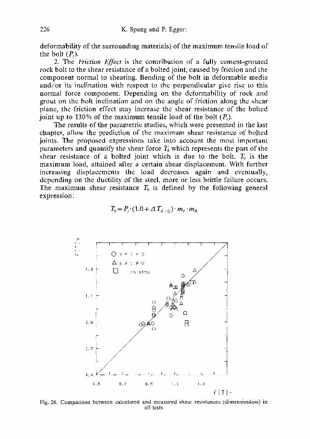
The results of the parametric studies, which were presented in the last chapter, allow the prediction of the maximum shear resistance of bolted joints. The proposed expressions take into account the most important parameters and quantify the shear force To which represents the part of the shear resistance of a bolted joint which is due to the bolt. To is the maximum load, attained after a certain shear displacement. With further increasing displacements the load decreases again and eventually, depending on the ductility of the steel, more or less brittle failure occurs. The maximum shear resistance To is defined by the following general expression:
TO= P/(1.0+ ZI TA+o)" mF'mR
>
1.3
1,1
I I I
0 ~=i= 0
f~i#o []
0,5
0.5 0.?
I I I I I I /
J- in situ O c ) ~ ~ /
B /
I I I I I
0.9 1.1 1 .3
F[TIr
Fig. 26. Comparison between calculated and measured shear resistances (dimensionless) in all tests
Action of Fully-Grouted Bolts in Jointed Rock 227
or, in an explicite way (with E M in kN/mm, oc in MPa and P~ in kN):
To = P~" [1.55 + 0.011. E M ~5. sin 2 (c~ + i)]. E M - o 2 . (0.85 + 0.45 .tan ~b)
o r
To = P,.[1.55 + 0.011. o-J~ (c~ + i)]. o-c-~ + 0.45.tan @).
In order to demonstrate the reliability of the proposed expressions, the maximum shear force To was calculated and plotted for all tests (see Fig. 26) in terms o f f ( T ) r (maximum values for f ( T ) of computed results) vs. f ( T ) u (maximum values for f ( T ) of test results). The points which show the worst agreement between the prediction and test results concern three field tests: in one case the test had to be disrupted before reaching the maximum load, in the two other cases the rebars had been damaged by welding during the installation.
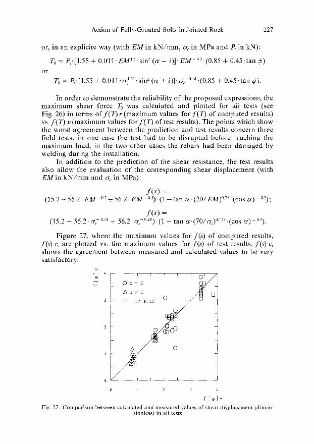
In addition to the prediction of the shear resistance, the test results also allow the evaluation of the corresponding shear displacement (with E M in k N / m m and oc in MPa):
f ( s ) = (15.2 - 55.2" E M - 02 + 56.2" E M - 0.4) "(1 - tan c~. ( 2 0 / E M ) ~ o 0 - 0.5);
f ( s ) = (15.2 - 55.2. o'~- o.14 + 56.2. o-~- ~ - tan c~. (70/o-c)~ (cos cr - o.5).
Figure 27, where the maximum values for f ( s ) of computed results, f ( s ) r, are plotted vs. the maximum values for f ( s ) of test results, f ( s ) u, shows the agreement between measured and calculated values to be very satisfactory.
>
~_ ~_ o ~ = o ~ / ~ I A c ~ # 0
3 i ] [] i~-~i~u o 0
2
1 Q I [ I F I .
0 I 2 3 4
Fig. 27. Comparison between calculated and measured values of shear displacement (dimen- sionless) in all tests
228 K. Spang and P. Egger:
Because of the empirical nature of the expressions given above, their validity is subjected (unless additional tests are carried out) to the following conditions:
-- Bolts consist of steel rebars or threaded bars and are fully grouted with cement mortar.
- - Borehole diameter is approximately twice that of the bolt. - - Strength of the rock is cr c > 10 MPa or its penetration modulus E M >
7 k N / m m ; limits for the calculation: 10 < Gc < 70 MPa or 7 < E M < 20 kN/mm.
- - B o l t inclination: 0~176 limits for the calculation of f : 0 o < G<30 ~
6 . C o n c l u s i o n s
The extensive experimental and numerical research work described above permits the following main conclusions:
The contribution of fully cement-grouted bolts to the shear resistance of rock joints depends strongly on a series of parameters:
- - High friction along the joint increases this contribution by as much as 50 % with respect to a frictionless joint.
- - Inclination of the bolt or dilatancy of the joint also increases this contri- bution up to approximately 20% with respect to bolts normal to the shear surface.
- - To a lesser degree, the shear resistance of bolted joints increases with the deformability of rock and grout.
The shear displacements required for obtaining the maximum shear load also depend on the above-mentioned parameters. In particular, incli- nation of the bolt and dilatancy of the joint act effectively as stiffening factors, which may decrease the shear displacements by as much as a Factor 3.
For both the maximum shear load and the corresponding displace- ments, empirical expressions are proposed which show a good agreement with the test results within the investigated limits.
R e f e r e n c e s
Only the references quoted in the present paper are indicated in the following. Further references are given in the main report concerning this research work (Spang, 1988).
ADINA: Automatic Dynamic Incremental Nonlinear Analysis. User Manual, ADINA Engineering 9/81.
Azuar , J. J. (1977): Stabilisation des massifs rocheux fissures par barres d'acier scell6es. Rap. de Rech. LPC No. 73, Lab. Central des Ponts et Chaussees. Nov. 1977.
Azuar etal. (1979): Le renforcement des massifs rocheux par armatures passives. Proc. IV. Int. Conf. ISRM, Montreux 1979, L 23--30.
Action of Fully-Grouted Bolts in Jointed Rock 229
B j u r s t r 6 m , S. (1974): Shear Strength of Hard Rock Joints Reinforced by Grouted Untensioned Bolts. Proc. III. Int. Conf. ISRM, Denver 1974, HB, 1194ff.
D i g h t, P. M. (1982) : Improvement to the Stability of Rock Walls in Open Pit Mines. Ph. D. Thesis, Monash University, Australia, 1982.
E g g e r , P., F e r n a n d e z , H. (1983): Nouvelle presse triaxiale -- Etude de mod61es discontinus boulonn6s. Proc. V. Int. Conf. ISRM, Melbourne 1983, 171--175.
Egge r , P., S p a n g , K. (1987): Stability Investigations for G r o u n d Improvement by Rock Bolts at a Large Dam. Proc. VI. Int. Conf. ISRM, Montreal 1987, 349--354.
H a a s , C. J. (1981): Analysis of Rockbolting to Prevent Shear Movement in Fractured Ground. Journ. of Mining Engineering 6, 698--704.
H a a s , C. J. (1976): Shear Resistance of Rock Bolts. Transactions, 260, 32--41.
H i b i n o , S., M o t o j i m a , M. (1981): Effects of Rock Bolting in Jointy Rock. Proc. Int. Syrup. Weak Rock, Tokyo 1981, 1052--1062.
S c h u b e rt, P. (1984): Das Tragverm6gen des m6rtelversetzten Ankers unter aufgezwungener Kluftverschiebung. Ph. D. Thesis, Montan-Universit~it Leoben, Austria, 1984.
S p an g, K. (1988): Beitrag zur rechnerischen Berficksichtigung vollvermOr- telter Anker bei der Sicherung von Felsbauwerken in geschichtetem oder gekltiftetem Gebirge. P h . D . Thesis, No. 740, Federal Institute of Technology, Lausanne, Switzerland, 1988.