
SPAF 340 C Frequency Relay - ABB Ltd · SPAF 340 C Frequency Relay ... the serial bus. 3...
64
SPCF 1D15 TRIP RESET STEP 0024A PROGRAM IRF f U f < > < > df dt SGR SGB SGF [ ] n f U / < Hz n U [ ] f Hz ∆ [ ] r t s > [ ] df dt / / Hz s [ ] 1 t s > [ ] 1 f Hz [ ] 4 t s > [ ] 4 f Hz [ ] 3 t s > [ ] 3 f Hz [ ] 2 t s > [ ] 2 f Hz Ser.No. SPAF 340 C3 0478A aux 18...80 V – 80...265 V ~ – U1 U2 U3 OPERATION INDICATORS U 2 5 n U = 100V/110V/115V/120V RS 454 004 - SPCF 1D15 0 Stage 1 Trip 2 Stage 2 Start 3 Stage 2 Trip 4 Stage 3 Start 5 Stage 3 Trip 6 Stage 4 Start 7 Stage 4 Trip 8 Rec. Due 9 Rec. Over A Stage 1 Start 1 Stage 1 Trip 2 Stage 2 Start 3 Stage 2 Trip 4 Stage 3 Start 5 Stage 3 Trip 6 Stage 4 Start 7 Stage 4 Trip 8 Rec. Due 9 Rec. Over A Stage 1 Start 1 0061A SPC 000 0061A SPC 000 SPAF 340 C Frequency Relay User´s manual and Technical description
Transcript of SPAF 340 C Frequency Relay - ABB Ltd · SPAF 340 C Frequency Relay ... the serial bus. 3...

SPCF 1D15
TRIP
RESETSTEP
0024
A
PROGRAM
IRFfU
f <>
<>dfdt
SGR
SGB
SGF
[ ]nf
U /<
Hz
nU
[ ]f Hz∆[ ]rt s>
[ ]df dt/ /Hz s
[ ]1t s>[ ]1f Hz
[ ]4t s>[ ]4f Hz
[ ]3t s>[ ]3f Hz
[ ]2t s>[ ]2f Hz
Ser.No.
SPAF 340 C3
0478
A
aux
18...80 V –
80...265 V ~–
U1 U2 U3OPERATION INDICATORS
U
2
5nU = 100V/110V/115V/120V
RS 454 004 -
SPCF 1D15
0
Stage 1 Trip2
Stage 2 Start3
Stage 2 Trip4
Stage 3 Start5
Stage 3 Trip6
Stage 4 Start7
Stage 4 Trip8
Rec. Due9
Rec. OverA
Stage 1 Start1
Stage 1 Trip2
Stage 2 Start3
Stage 2 Trip4
Stage 3 Start5
Stage 3 Trip6
Stage 4 Start7
Stage 4 Trip8
Rec. Due9
Rec. OverA
Stage 1 Start1
0061
A
SPC 000
0061
A
SPC 000
SPAF 340 CFrequency Relay
User´s manual and Technical description
2
1MRS 750582-MUM EN
Issued 1996-11-07Modified 2004-03-16Version DChecked PSApproved MÖ
Data subject to change without notice
SPAF 340 CFrequency Relay
Contents Features .......................................................................................................................... 2Application ..................................................................................................................... 3Description of operation ................................................................................................. 3Connections (modified 2003-09) .................................................................................... 4Specification of input and output terminals (modified 2004-03) ..................................... 6Operation indicators ....................................................................................................... 7I/O module .................................................................................................................... 8Power supply module ...................................................................................................... 8Technical data (modified 2002-04) .................................................................................. 8Applications (modified 2003-09) ................................................................................... 11Testing .......................................................................................................................... 20Maintenance and repair ................................................................................................ 21Spare parts .................................................................................................................... 21Order numbers ............................................................................................................. 21Dimension drawings and mounting.............................................................................. 22Ordering information ................................................................................................... 22
In addition to the general part, the complete manual of the frequency relay SPAF 340 Cincludes the following relay module descriptions:
Combined frequency and rate of change of frequency relay module 1MRS 750583-MUM ENGeneral characteristics of D-type SPC relay modules 1MRS 750066-MUM EN
Features Single-phase four-stage combined overfre-quency/underfrequency relay
Each protection stage includes a frequency rateof change function (df/dt), which can be usedalone or in combination with the overfrequency/underfrequency function.
Each protection stage includes two separateadjustable timers
Recovery function
Programmable undervoltage blocking
Four rated voltages, to be selected in the soft-ware
Adjustable rated frequency
Five external control inputs enabling separateblocking of each stage, etc.
Eight freely configurable output relays and self-supervision output relay
Four trip contacts
Recording of measured data, which can be usedfor analysing the network condition.
Transfer of data over serial communication bus
Continuous self-supervision with internal faultdiagnosis
Reading and writing of setting values via dis-play and front panel push-buttons, a PC withsetting software or from higher system levels overthe serial bus.

3
Application The frequency relay SPAF 340 C3 is speciallydesigned to be used for automatic disconnec-tion of loads in situations, where the loads con-nected to the network exceed the available powercapacity of the network. Such a power deficiencycauses the frequency of the network to drop ata rate of change that is directly proportional tothe power deficiency and inversely proportionalto the rotating mass of the generators connectedto the network.
The SPAF 340 C3 relay allows 4-step load-shed-ding and is capable of operating four circuitbreakers. A total of eight timers, freely selectablerelay outputs and the df/dt function of the re-lay enable a load-shedding logic, which can sensethe rate of change of the network frequency aswell.
In addition, the frequency relay SPAF 340 C3can be used for protecting generators, large syn-chronous motors and other electrical equipmentagainst overfrequency and underfrequency.
The frequency relay SPAF 340 C is a secondaryrelay, which is connected to the voltage trans-formers of the network section to be protected.The relay incorporates one relay module: thecombined frequency and rate of change of fre-quency module type SPCF 1D15.
Combined frequency and rate of change of fre-quency relay module
The relay module includes four protectionstages, each of which with its own frequencyfunction (f ), its own rate of change of frequencyfunction (df/dt) and two adjustable operatetimes (t and t’).
When the frequency limit of a stage is set belowthe rated frequency, the protection stage oper-ates as an underfrequency stage. Correspond-ingly, the stage has the function of an over-frequency stage, when the frequency level is set
above the rated frequency. The frequency set-ting cannot be the same as the rated frequency.
The operation of the df/dt function of a pro-tection stage is based on the same principle asthe frequency function, which means that if aprotection stage operates as an underfrequencystage, the sign of the df/dt function is negative.Then the df/dt function starts once the abso-lute value of the rate of frequency drop exceedsthe df/dt limit. When required, the frequencyfunction and the df/dt function can be com-bined so that the criteria for operation of bothfunctions have to be fulfilled at the same time.
Once a preset condition is fulfilled, the stagestarts and, at the same time, it activates a tim-ing circuit. No start signal can be programmedfor the output relays. When the stage times out,the relay produces a trip signal. The trip signalcan be linked to the desired output relay.
Description ofoperation

4
Connections(modified 2003-09)
Fig. 1. Connection diagram for frequency relay SPAF 340 C
IRF
SS
1T
S1
SS
2T
S2
SS
3T
S3
SS
4T
S4
I/OB
S1
BS
2B
S5
BS
4B
S3
U1
4f4df/dt
X1
109
87
65
43
21
BS
3B
S4
BS
5B
S2
BS
1
X0
6313
1416
1719
201
23
45
67
89
2829
2526
27
100V
100V
100V
5A
1A
5A
1A
5A
1A
100V
X0
6261
Uaux
+- =
~_
+ (~
)
- (~)
X2
1514
16X
212
13X
23
4X
29
1011
X2
12
X2
78
X2
56
X1
1516
X1
1112
1314
IRF
SS
1T
S1
SS
2T
S2
SS
3T
S3
SS
4T
S4
SE
RIA
LP
OR
T(S
PA
)
++
++
++
++
+
SPA-ZC_
Rx
Tx
U5
a n
d
N A
5A
1A

5
Uaux Auxiliary voltageTS1...TS4 Output relays (heavy-duty)SS1...SS4 Output relaysIRF Self-supervision output relayBS1...BS5 Control signalsU1 Combined frequency and rate of change of frequency relay
moduleSERIAL PORT Serial communication portSPA-ZC_ Bus connection moduleRx/Tx Fibre-optic cable connection
Fig. 2. Terminals of frequency relay SPAF 340 C
X0
U23
1
2
34
5
67
8
925
26
27
61
62
6313
14
28
29
16
17
19
20
IL1
IL2
IL3
I0 U0
U31
U12
Uau
xX2
SS1 SS3 SS4 TS1 TS2
16 15 14 13 12 11 10 9 8 7 6 5 4 3 2 1IRF SS2
X1
1 2 3 4 5 6 7 8 9 10 11 12 13 14 15 16BS1 BS2 BS5 BS4 BS3 TS4 TS3
Serial Port
SPA
Made in Finland
=63

6
Specification ofinput and outputterminals(modified 2004-03)
Terminal Terminal Functiongroup interval
X0 1-2 Phase current IL1 5 A *)1-3 Phase current IL1 1 A *)4-5 Phase current IL2 5 A *)4-6 Phase current IL2 1 A *)7-8 Phase current IL3 5 A *)7-9 Phase current IL3 1 A *)13-14 Phase-to-phase voltage U12 100 V16-17 Phase-to-phase voltage U23 100 V *)18-19 Phase-to-phase voltage U31 100 V *)25-26 Neutral current I0 1 A *)25-27 Neutral current I0 0.2 A *)28-29 Residual voltage U0 100 V *)
*) Inputs not used by the relay module SPCF 1D15. The inputs can be used for recording the signals via the disturbance recorder SPCR 8C27.
X0 61-62 Auxiliary voltage supply.The positive pole of the DC supply is connected to terminal 61.The auxiliary voltage range is marked on the front plate.
63 Protective earth
X1 1-2 External blocking signal BS13-4 External blocking signal BS25-6 External blocking signal BS57-8 External blocking signal BS49-10 External blocking signal BS3
X2 1-2 Output relay TS1 (heavy-duty)3-4 Output relay TS2 (heavy-duty)
X1 15-16 Output relay TS3 (heavy-duty)11-12-13-14 Output relay TS4 (heavy-duty; terminals 12 and 13 to be
connected together, unless two-pole control is used)
X2 5-6 Output relay SS47-8 Output relay SS39-10-11 Output relay SS212-13 Output relay SS114-15-16 Output relay IRF
The protection relay connects to the fibre-op-tic data bus via the bus connection module SPA-ZC 17 or SPA-ZC 21 to be fitted to the D con-nector on the rear panel of the relay. The opti-
cal fibres are connected to the counter contactsRx and Tx of the module. The selector switchesof the bus connection module should be in theposition "SPA".

7
Operationindicators
SPCF 1D15
TRIP
RESETSTEP
0024
A
PROGRAM
IRFfU
f <>
<>dfdt
SGR
SGB
SGF
[ ]nf
U /<
Hz
nU
[ ]f Hz∆[ ]rt s>
[ ]df dt/ /Hz s
[ ]1t s>[ ]1f Hz
[ ]4t s>[ ]4f Hz
[ ]3t s>[ ]3f Hz
[ ]2t s>[ ]2f Hz
Ser.No.
SPAF 340 C3
0478
A
aux
18...80 V –
80...265 V ~–
U1 U2 U3OPERATION INDICATORS
U
2
5nU = 100V/110V/115V/120V
RS 454 004 -
SPCF 1D15
0
Stage 1 Trip2
Stage 2 Start3
Stage 2 Trip4
Stage 3 Start5
Stage 3 Trip6
Stage 4 Start7
Stage 4 Trip8
Rec. Due9
Rec. OverA
Stage 1 Start1
Stage 1 Trip2
Stage 2 Start3
Stage 2 Trip4
Stage 3 Start5
Stage 3 Trip6
Stage 4 Start7
Stage 4 Trip8
Rec. Due9
Rec. OverA
Stage 1 Start1
0061
A
SPC 000
0061
A
SPC 000
Fig. 3. Front panel of frequency relay SPAF 340 C
1. The green LED indicator Uaux on the sys-tem panel is lit when the power supply isoperating.
2. Measured values, settings and start and tripdata are indicated on the display. Starting andtripping are indicated by a red operation codeto the left of the display. The operation codesare explained in the descriptions of the relaymodules and on the system panel of the fre-quency relay.
Start indications can be programmed to re-main lit, even though the stage resets. In gen-eral, the numbers indicating start are auto-matically reset, whereas trip codes have to bemanually reset by pressing the RESET push-button. The TRIP indicator at the bottompart of the front panel can be set to indicatetripping of any stage. The BS_ signals can beconfigured to automatically reset the tripindicators. A non-reset operation indicatordoes not affect the operation of the relaymodule.
3. A measured or set value presented on the dis-play is identified by yellow LEDs on the frontpanel.
4. A permanent fault detected by the self-supervision system is indicated by the IRFindicator of the concerned relay moduleand a fault code on the display of the relaymodule. The fault code should be recordedto facilitate maintenance and repair.
The operation indicators are described in moredetail in the descriptions of the relay modules.

8
I/O module The I/O module SPTR 9B25 of the frequencyrelay is located in the rear part of the relay, andplaced in the same direction as the mother PCboard. The module can be withdrawn after un-doing the fixing screws and disconnecting theprotective earth conductor and the flat cableconnected to the mother PC board.
The I/O module contains the output relays (8+ IRF), the control circuits of the relays, theelectronic circuits of the five control inputs andthe D connector required for the serial com-munication. The input and output signals ofthe I/O module are linked to the mother PCboard over the flat cable. The relay module lo-cations U1, U2 and U3 are identical.
The output signals SS1...SS4 and TS1...TS4 ofthe mother PC board control an output relaywith the same designation. The operation of astage is not fixed to a specific output relay, butcan be configured for the desired relay. How-ever, it should be noted that the output relaysTS1...TS4 can be used for circuit breaker con-trol. The configuration of the switchgroups isdescribed in the module-specific manuals.
The switchgroups of the relay modules are usedfor configuring the external control inputs,which can be used for blocking one or severalprotection stages, resetting operation indicatorsor selecting second settings, etc.
Power supplymodule
The power supply module forms the voltagesrequired by the relay modules and the auxiliaryrelay module. The power supply module is situ-ated behind the system panel of the relay and itcan be withdrawn after removal of the systempanel.
The power supply module is available in twoversions with the following input voltages:
SPGU 240 A1:- rated voltage Un = 110/120/230/240 V ac
Un = 110/125/220 V ac/dc- operative range U = 80...265 V ac/dc
SPGU 48B2- rated voltage Un = 24/48/60 V dc- operative range U = 18...80 V dc
The voltage range of the power supply moduleof the relay is marked on the system panel ofthe relay.
The power supply module is transformer-con-nected, i.e. the primary circuits and the second-ary circuits are galvanically isolated. The pri-mary side is protected by a fuse, F1, located onthe PC board of the module. The fuse used inSPGU 240A1 is 1 A (slow) and the one used inSPGU 48B2 is 4 A (slow).
The green LED indicator Uaux on the frontpanel is lit, when the power supply module isin operation. The supervision of the voltagessupplying the electronic circuits is integratedinto the relay modules. A self-supervision alarmis received as soon as a secondary voltage devi-ates from the rated value by more than 25%.An alarm signal is also generated if the powersupply module is removed or the auxiliary volt-age supply to the relay is interrupted.
Technical data(modified 2002-04)
Energizing inputsRated current In 1 A 5 A
Terminal numbers X0/1-3 X0/1-2X0/4-6 X0/4-5X0/7-9 X0/7-8X0/25-27 X0/25-28
Thermal current withstand- continuously 4 A 20 A- for 10 s 25 A 100 A- for 1 s 100 A 500 A
Dynamic current withstand- half-wave value 250 A 1250 A
Input impedance <100 mΩ <20 mΩ

9
Voltage inputsRated voltage Un (programmable) 100 V (110 V, 115 V, 120 V)
Terminal numbers X0/13-14, 16-17, 19-20, 28-29Continuous voltage withstand 2 x UnRated burden of voltage input at Un <0.5 VA
Output contactsTrip contactsTerminal numbers X2/3-4, 1-2
X1/15-16, 11-12-13-14Rated voltage 250 V ac/dcContinuous current carrying capacity 5 AMake and carry 0.5 s 30 AMake and carry 3 s 15 ABreaking capacity for dc when the control circuit timeconstant L/R ≤40 ms at the control voltage levels- 220 V dc 1 A- 110 V dc 3 A- 48 V dc 5 A
Signal contactsTerminal numbers X2/12-13, 9-10-11
X2/7-8, 5-6, 14-15-16Rated voltage 250 V ac/dcContinuous current carrying capacity 5 AMake and carry 0.5 s 10 AMake and carry 3 s 8 ABreaking capacity for dc when the control circuit timeconstant L/R ≤40 ms at the control voltage levels- 220 V dc 0.15 A- 110 V dc 0.25 A- 48 V dc 1 A
External control inputsBlocking/control (BS1...BS5)Terminal numbers X1/1-2, 3-4, 9-10, 7-8, 5-6External control voltage 18...250 V dc or 80...250 V acCurrent drain of activated control input 2...20 mA
Power supply moduleSPGU 240A1Rated voltage Un = 100/120/230 V ac
Un = 110/125/220 V acOperative range U = 80...265 V dc
SPGU 48B2Rated voltage Un = 24/48/60 V dcOperative range U = 18...80 V dcPower consumption under quiescent/operation conditions 15 W/20 W

10
Combined frequency and rate of change of frequency relay module SPCF 1D15- see "Technical data" in the description of the module.
Data communicationTransmission mode Fibre-optic serial busCoding ASCIIData transfer rate, selectable 4800 Bd or 9600 Bd
Bus connection modules for fibre-optic data transfer- for plastic core cables SPA-ZC 21 BB- for glass-fibre cables SPA-ZC 21 MM
Modules with internal power supply unit- for plastic core cables SPA-ZC 17 BB- for glass-fibre cables SPA-ZC 17 MM
Insulation Tests *)Dielectric test IEC 60255-5 2 kV, 50 Hz, 1 minImpulse voltage test IEC 60255-5 5 kV, 1.2/50 µs, 0.5 JInsulation resistance measurement IEC 60255-5 >100 MΩ, 500 Vdc
Electromagnetic Compatibility Tests *)High-frequency (1 MHz) burst disturbance testIEC 60255-22-1- common mode 2.5 kV- differential mode 1.0 kVElectrostatic discharge test IEC 60255-22-2 andIEC 61000-4-2- contact discharge 6 kV- air discharge 8 kVFast transient disturbance test IEC 60255-22-4and IEC 61000-4-4- power supply 4 kV- I/O ports 2 kV
Mechanical environmental testsVibration test, IEC 60255-21-1 class 2Chock/bump test, IEC 60255-21-2 class 2Seismic test, IEC 60255-21-3 class 2
Environmental conditionsService temperature range -10... +55°CTransport and storage temperature range -40...+70°CTemperature influence ±0.05‰/total temperature range,
frequency measurement<0.2%/°C, voltage measurement
Damp heat test 93...95%, +55°C, 6 cyclesDegree of protection by enclosure of flush-mounting relay case IP54Weight of fully equipped relay 6 kg
*) The tests do not apply to the serial port, which is used exclusively for the bus connection module.

11
Applications
Example 1.Four-step loadshedding accom-plished by usingfrequency relaySPAF 340 C3(modified 2003-09)
Fig. 4. Frequency relay SPAF 340 C3 used for load shedding
IRF
SS
1T
S1
SS
2T
S2
SS
3T
S3
SS
4T
S4
I/OB
S1
BS
2B
S5
BS
4B
S3
U1
4f4df/dt
X1
109
87
65
43
21
BS
3B
S4
BS
5B
S2
BS
1
X0
6313
1416
1719
201
23
45
67
89
2829
2526
27
100V
100V
100V
5A
1A
5A
1A
5A
1A
100V
X0
6261
Uaux
+- =
~_
+ (~
)
- (~)
X2
1514
16X
212
13X
23
4X
29
1011
X2
12
X2
78
X2
56
X1
1516
X1
1112
1314
IRF
SS
1T
S1
SS
2T
S2
SS
3T
S3
SS
4T
S4
SE
RIA
LP
OR
T(S
PA
)
++
++
++
++
+
SPA-ZC_
Rx
Tx
U5
5A
1A
Q2
Q3
Q4
Q5
Q6
Q1
a n
d
N A
d
Open Q
2O
pen Q3
Open Q
4O
pen Q5
Essential load
Alarm

12
The relay module SPCF 1D15 incorporates fourprotection stages. By using all of these stagesand giving each stage its own start values andoperate times such a load shedding system canbe achieved that senses rates of change in situ-ations of power deficiency.
In a situation of power deficiency, the feedersare disconnected in such a sequence that thefeeder of the lowest priority is the first one tobe disconnected and that of the highest prioritythe last one to be disconnected. When a load-shedding system is constructed, it should benoticed that the feeders to be disconnected areloaded. This means that the feeders have an in-fluence on the restoration of the power balance.
In the application of the example four protec-tion stages are used. Each stage has two outputsignals with different operate times. One of theoperate times is relatively long and intended tobe used in situations with rather small powerdeficiencies and slow frequency declines. This
delay allows the frequency to fall below the startlevel momentarily; no loads are disconnectedwhen the power regulators are able to restorethe power balance. In addition, a long operatetime gives the network and the power regula-tors time to respond to load disconnection car-ried out by a higher stage.
The short operate time of the stage allows loadsto be disconnected quickly in a situation of greatpower deficiency. The shorter operate time isconnected to control the circuit breaker whichshould operate earlier according the protectionscheme, so the load is always shed in the de-sired sequence. Thus, the shorter operate timeof a stage always "speeds up" the operation ofthe previous load-shedding stage.
The start values and operate times of the stagesand the timers controlling the individual cir-cuit breakers are shown in Fig. 5. The designa-tions used in Fig. 5 refer to Fig. 4.
Stage Operate value Delay Timer Relay output Function
1 48.7 0.15 t1 SS1 Alarm20 t1’ TS1 Q2 open
2 48.5 0.15 t2 TS1 Q2 open20 t2’ TS2 Q3 open
3 48.3 0.15 t3 TS2 Q3 open20 t3’ TS3 Q4 open
4 48.1 0.15 t4 TS3 Q4 open5 t4’ TS4 Q5 open
Fig. 5. The settings of the stages of the frequency relay SPAF 340 C3 used for load shedding.
The above mentioned arrangement for speeding up the operation of the stages is illustrated in Fig. 6.

13
Fig. 7. Opening delay of feeder Q2 at two ratesof frequency drop, example 1.
50
f/[Hz]
49
48,5
48
48,3
1.
2.
0,15s
20s
t/[s]
As shown in Fig. 7, a lower-set stage discon-nects the loads of the next, higher stage, whenthe power declines rapidly. The advantage of thisarrangement is that, when the frequency fallsslowly, the power regulators have enough timeto operate. When, on the other hand, the powerdeficiency is the result of a sudden, substantialchange, the loads can be disconnected rapidlyenough and in the required succession.
Figure 7 illustrates the disconnection of feederQ2 referred to in Fig. 4, in different situations.
Fig. 6. Use of the timer function of frequency relay SPAF 340 C3 in a load shedding.
f1
<48.7 Hz 0.15 s
t1
20 s
t1'
SS1
TS1
f2
<48.5 Hz 0.15 s
t2
20 s
t2'
TS2
f3
<48.3 Hz 0.15 s
t3
20 s
t3'
TS3
f4
<48.1 Hz 0.15 s
t4
TS45 s
t4'
fmeasured
Stage 2
Stage 1
Open Q5
Stage 4
open Q4
Stage 3
Alarm
Open Q2
open Q3

14
In the case described in example 1 the switchesof the frequency relay SPAF 340 C3 can beconfigured as follows:
Switch- Serial comm. Checksum Operationgroup parameter
SGF1 S84 1 Only frequency functionSGF2 S85 1 Only frequency functionSGF3 S86 1 Only frequency functionSGF4 S87 1 Only frequency functionSGF5 S88 255 Output continuously operatedSGF6 S89 254 SS2...SS4 and TS1...TS4 linked to TRIP LEDSGF7 S90 0 Un = 100 V
SGB1 S91 0 No external control signals usedSGB2 S92 0 No external control signals usedSGB3 S93 0 No external control signals usedSGB4 S94 0 No external control signals usedSGB5 S95 0 No external control signals usedSGB6 S96 15 Undervoltage blocking for all stages
SGR1 S97 1 Underfrequency signal to alarm contact SS1SGR2 S98 2 Stage 1 (timer t’) linked to trip contact TS1SGR3 S99 2 Stage 2 (timer t) linked to trip contact TS1SGR4 S100 8 Stage 2 (timer t’) linked to trip contact TS2SGR5 S101 8 Stage 3 (timer t)linked to trip contact TS2SGR6 S102 32 Stage 3 (timer t’) linked to trip contact TS3SGR7 S103 32 Stage 4(timer t) linked to trip contact TS3SGR8 S104 128 Stage 4 (timer t’) linked to trip contact TS4SGR9 S105 0 No recovery function

15
Example 2.Four-step loadshedding logicbased on the useof the frequencyrelay SPAF 340 C3(modified 2003-09)
The load shedding arrangement presented inexample 2 is, in principle, the same as that ofexample 1. The only difference is that the rate
of change of frequency is used to speed up theoperation of the protection.
Fig. 8. Frequency relay SPAF 340 C3 used for load shedding
IRF
SS
1T
S1
SS
2T
S2
SS
3T
S3
SS
4T
S4
I/OB
S1
BS
2B
S5
BS
4B
S3
U1
4f4df/dt
X1
109
87
65
43
21
BS
3B
S4
BS
5B
S2
BS
1
X0
6313
1416
1719
201
23
45
67
89
2829
2526
27
100V
100V
100V
5A
1A
5A
1A
5A
1A
100V
X0
6261
Uaux
+- =
~_
+ (~
)
- (~)
X2
1514
16X
212
13X
23
4X
29
1011
X2
12
X2
78
X2
56
X1
1516
X1
1112
1314
IRF
SS
1T
S1
SS
2T
S2
SS
3T
S3
SS
4T
S4
SE
RIA
LP
OR
T(S
PA
)
++
++
++
++
+
SPA-ZC_
Rx
Tx
U5
5A
1A
Q1
Q2
Q3
Q4
Q5
N A
ad
n
d
Open Q
1O
pen Q2
Open Q
3O
pen Q4
Essential load
Start signal
of restoration

16
In addition to the normal underfrequency func-tion, each protection stage incorporates a com-bined underfrequency and df/dt function. Theoperate time of the underfrequency function israther long and it is intended to be used in situ-ations where the power deficiency is small andthe frequency declines slowly. The use of theunderfrequency function and a long operatetime is described in example 1.
The operate time of the combined under-frequency and df/dt function is short. This com-bined protection is intended to be used in situ-ations where a power deficiency occurs suddenly,that is, the frequency falls rapidly. In cases, wherejust the frequency function and a long operatetime are used, the frequency may suddenly fallso much that it is dangerous for the generators.
When the df/dt function is combined with thefrequency function, the operation of the pro-tection can be speeded up, allowing the loadsto be disconnected early enough and furtherdevelopment of the power deficiency to behalted.
The rate of change of frequency function canbe used alone, but it is always safer to use it inconjunction with the underfrequency function.During normal network operation in the ratedfrequency range fast frequency swings may oc-cur. If the df/dt function in combination with ashort operate time is used, without the under-frequency function, these swings may result intripping. The designations used in Fig. 9 referto Fig. 8.
Stage Timer Function Setting f Setting df/dt Delay Relay Operation[Hz] [Hz/s] [s] output
1 t1 <f and <df/dt 48.8 -1 0.20 TS1 Q1 opent1' <f 48.8 5.00 TS1 Q1 open
2 t2 <f and <df/dt 48.3 -1 0.20 TS2 Q2 opent2' <f 48.3 5.00 TS2 Q2 open
3 t3 <f and <df/dt 47.8 -1 0.20 TS3 Q3 opent3' <f 47.8 5.00 TS3 Q3 open
4 t4 <f and <df/dt 47.5 -1 0.20 TS4 Q4 opent4' <f 47.5 5.00 TS4 Q4 open
Fig. 9. Settings of the protection stages of frequency relay SPAF 340 C3 used for load shedding
The start values and the operate times of theindividual protection stages and the timers con-
trolling the individual circuit breakers are shownin Fig. 9.

17
Fig. 10. Configuration of the relay module SPCF 1D15.
f1
<48.8 Hz 0.20 s
t1TS1
TS1
df1/dt
<-1 Hz/s
&
5 s
t1'
TS2
f2
<48.3 Hz
df2/dt
<-1 Hz/s
& 0.20 s
t2
5 s
t2'
TS2
TS3
f3
<47,8 Hz
df3/dt
<-1 Hz/s
& 0,20 s
t3
5 s
t3'
TS3
TS4
f4
<47.5 Hz
df4/dt
<-1 Hz/s
& 0.20 s
t4
5 s
t4'
TS4
&SS4
>(50-0.3)Hz
<(50+0.3)Hz
30 s
tr
fmeasured
Open Q1
Stage 1
Open Q1
Open Q2
Stage 2
Open Q2
Open Q3
Stage 3
Open Q3
Open Q4
Stage 4
Open Q4
Recovery function
Start ofrecoveryfunction

18
The recovery function is also used in example2. Once a protection stage has issued a trip sig-nal the recovery function is activated and, atthe same time, the normally operated output ofthe recovery function drops out. When the fre-quency has returned to a normal value withinthe selected range, the operate time of the re-covery stage starts. Should the frequency remainwithin the permitted range throughout the op-
erate time, the recovery function operates andthe corresponding output picks up. If the fre-quency deviates from the setting range duringthe operate time of the recovery function, thetimer stops and then continues when the fre-quency returns to normal. The operate time ofthe recovery function is reset to zero, if one ofthe protection stages delivers a trip signal dur-ing the operate time.
50
f/[Hz]
4948,8
48
t/[s]
trip
activating of recovery function
start of operate time counter
operate time counter suspended operate time counter continues
operate time counter timed out
recovery output drops outrecovery output picks up
connection of auxiliary voltage supply
length of output pulse
connection of auxiliary voltage supplyrecovery output drops out
recovery output picks up
operation of recovery output when pulse output is used (alternative function)
Fig. 11. Operation of recovery stage

19
In the case described in example 2 the switchesof the frequency relay SPAF 340 C3 can beconfigured as follows:
Switch- Serial comm. Checksum Operationgroup parameter
SGF1 S84 2 Combined frequency and df/dt functionSGF2 S85 2 Combined frequency and df/dt functionSGF3 S86 2 Combined frequency and df/dt functionSGF4 S87 2 Combined frequency and df/dt functionSGF5 S88 255 Outputs continuously operatedSGF6 S89 254 SS2...SS4 and TS1...TS4 linked to TRIP LEDSGF7 S90 0 Un = 100 V
SGB1 S91 0 No external control signalsSGB2 S92 0 No external control signalsSGB3 S93 0 No external control signalsSGB4 S94 0 No external control signalsSGB5 S95 0 No external control signalsSGB6 S96 15 Undervoltage blocking for all stages
SGR1 S97 2 Stage 1 linked to trip contact TS1SGR2 S98 2 Stage 1 linked to trip contact TS1SGR3 S99 8 Stage 2 linked to trip contact TS2SGR4 S100 8 Stage 2 linked to trip contact TS2SGR5 S101 32 Stage 3 linked to trip contact TS3SGR6 S102 32 Stage 3 linked to trip contact TS3SGR7 S103 128 Stage 4 linked to trip contact TS4SGR8 S104 128 Stage 4 linked to trip contact TS4SGR9 S105 64 Recovery output linked to contact SS4
20
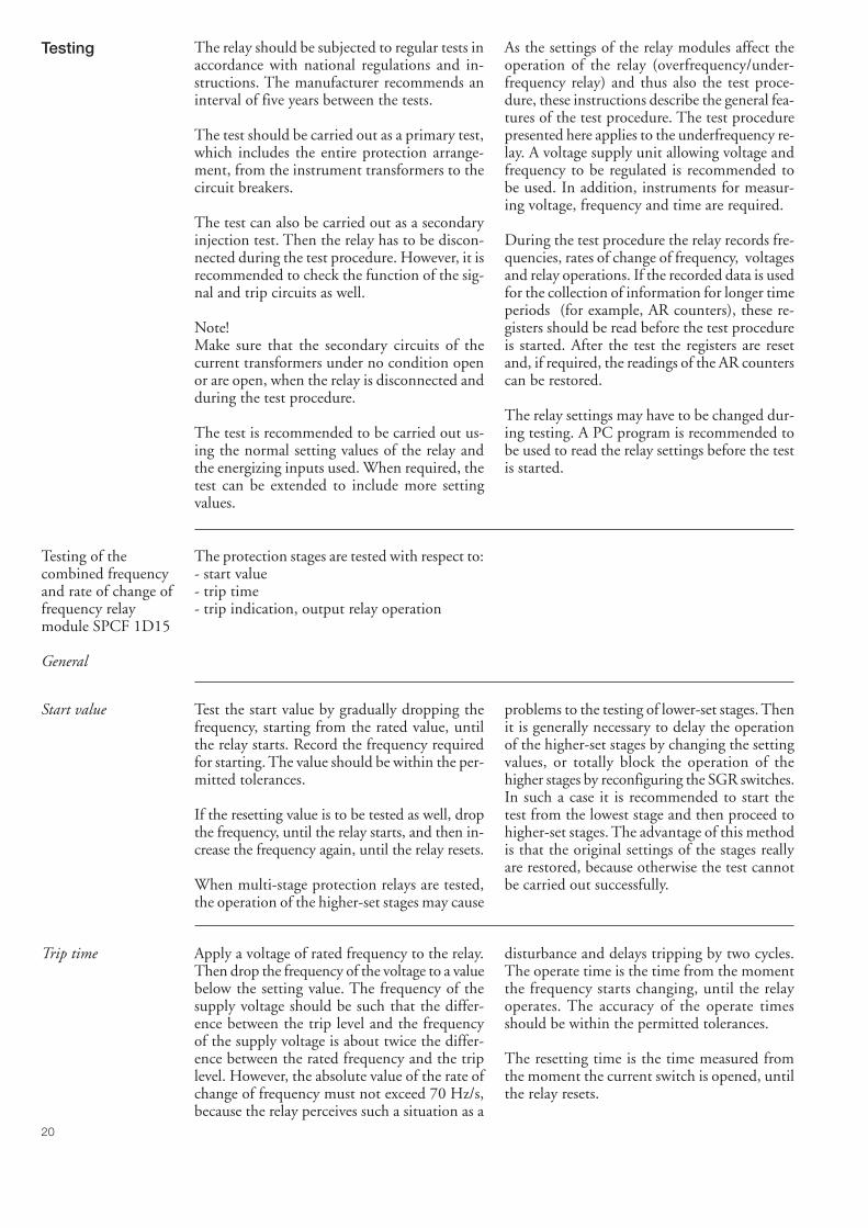
Testing The relay should be subjected to regular tests inaccordance with national regulations and in-structions. The manufacturer recommends aninterval of five years between the tests.
The test should be carried out as a primary test,which includes the entire protection arrange-ment, from the instrument transformers to thecircuit breakers.
The test can also be carried out as a secondaryinjection test. Then the relay has to be discon-nected during the test procedure. However, it isrecommended to check the function of the sig-nal and trip circuits as well.
Note!Make sure that the secondary circuits of thecurrent transformers under no condition openor are open, when the relay is disconnected andduring the test procedure.
The test is recommended to be carried out us-ing the normal setting values of the relay andthe energizing inputs used. When required, thetest can be extended to include more settingvalues.
As the settings of the relay modules affect theoperation of the relay (overfrequency/under-frequency relay) and thus also the test proce-dure, these instructions describe the general fea-tures of the test procedure. The test procedurepresented here applies to the underfrequency re-lay. A voltage supply unit allowing voltage andfrequency to be regulated is recommended tobe used. In addition, instruments for measur-ing voltage, frequency and time are required.
During the test procedure the relay records fre-quencies, rates of change of frequency, voltagesand relay operations. If the recorded data is usedfor the collection of information for longer timeperiods (for example, AR counters), these re-gisters should be read before the test procedureis started. After the test the registers are resetand, if required, the readings of the AR counterscan be restored.
The relay settings may have to be changed dur-ing testing. A PC program is recommended tobe used to read the relay settings before the testis started.
Testing of thecombined frequencyand rate of change offrequency relaymodule SPCF 1D15
General
The protection stages are tested with respect to:- start value- trip time- trip indication, output relay operation
Start value Test the start value by gradually dropping thefrequency, starting from the rated value, untilthe relay starts. Record the frequency requiredfor starting. The value should be within the per-mitted tolerances.
If the resetting value is to be tested as well, dropthe frequency, until the relay starts, and then in-crease the frequency again, until the relay resets.
When multi-stage protection relays are tested,the operation of the higher-set stages may cause
problems to the testing of lower-set stages. Thenit is generally necessary to delay the operationof the higher-set stages by changing the settingvalues, or totally block the operation of thehigher stages by reconfiguring the SGR switches.In such a case it is recommended to start thetest from the lowest stage and then proceed tohigher-set stages. The advantage of this methodis that the original settings of the stages reallyare restored, because otherwise the test cannotbe carried out successfully.
Trip time Apply a voltage of rated frequency to the relay.Then drop the frequency of the voltage to a valuebelow the setting value. The frequency of thesupply voltage should be such that the differ-ence between the trip level and the frequencyof the supply voltage is about twice the differ-ence between the rated frequency and the triplevel. However, the absolute value of the rate ofchange of frequency must not exceed 70 Hz/s,because the relay perceives such a situation as a
disturbance and delays tripping by two cycles.The operate time is the time from the momentthe frequency starts changing, until the relayoperates. The accuracy of the operate timesshould be within the permitted tolerances.
The resetting time is the time measured fromthe moment the current switch is opened, untilthe relay resets.

21
Maintenanceand repairs
When the protection relay is used under theconditions specified in "Technical data", it re-quires practically no maintenance. The relayincludes no parts or components that are sensi-tive to physical or electrical wear under normaloperating conditions.
Should the temperature and humidity at theoperating site differ from the values specified,or the atmosphere contain chemically activegases or dust, the relay should be visually in-spected in association with the secondary test-ing of the relay. This visual inspection shouldfocus on:
- Signs of mechanical damage to relay case andterminals
- Collection of dust inside the relay case; removewith compressed air
- Signs of corrosion on terminals, case or insidethe relay
If the relay malfunctions or the operating val-ues differ from those specified, the relay shouldbe overhauled. Minor measures can be takenby the customer but any major repair involvingthe electronics has to be carried out by themanufacturer. Please contact the manufactureror his nearest representative for further infor-mation about checking, overhaul and recalibra-tion of the relay.
The protection relay contains circuits sensitiveto electrostatic discharge. If you have to with-draw a relay module, ensure that you are at thesame potential as the module, for instance, bytouching the case.
Note!Protection relays are measuring instruments andshould be handled with care and protectedagainst moisture and mechanical stress, espe-cially during transport.
Spare parts Combined frequency and rate of change of frequency relay module SPCF 1D15Power supply modules- U = 80...265 V ac/dc (operative range) SPGU 240A1- U = 18...80 V dc (operative range) SPGU 48B2I/O module SPTR 9B25Case (including connection module) SPTK 8B17Bus connection module SPA-ZC 17_
SPA-ZC 21_
Order numbers Frequency relay SPAF 340 C3 without test adapter: RS 454 004-AA, CA
Frequency relay SPAF 340 C3 with test adapter RTXP 18: RS 454 204-AA, CA
The letter combinations of the order number indicate the rated frequency fnand the auxiliary voltage Uaux of the protection relay:
AA: fn = 50 Hz and Uaux = 80...265 V ac/dcCA: fn = 50 Hz and Uaux = 18...80 V dc

22
Dimensiondrawings andmounting
The basic model of the protection relay case isdesigned for flush-mounting. When required,the mounting depth of the case can be reduced
by using raising frames: type SPA-ZX 301 re-duces the depth by 40 mm, type SPA-ZX 302by 80 mm and type SPA-ZX 303 by 120 mm.
Example1. Number and type designation 10 SPAF 340 C units2. Order number RS 454 004 -AA3. Auxiliary voltage Uaux = 110 V dc4. Accessories 10 bus connection modules SPA-ZC 17 MM2A6. Special requirements –
Orderinginformation
The relay case is made of profile aluminium andpainted grey.
The rubber gasket fitted to the mounting collarprovides an IP 54 degree of protection by en-closure between the relay case and the mount-ing base.
The hinged cover of the case is made of trans-parent, UV-stabilized polycarbonate polymerand provided with two sealable locking screws.The rubber gasket of the cover provides an IP54 degree of protection between the case andthe cover.
The required input and output circuits are con-nected to the screw terminals on the rear panel.Terminal block X0 consists of screw terminalsfitted to the rear panel of the relay. The termi-nal blocks X1 and X2 are provided with discon-nectable multi-pole screw terminals. The male
parts of the disconnectable terminal blocks areattached to the I/O module. The female partsare included in the delivery. The female part canbe secured to the male part with fixing accesso-ries and screws.
Measured data, auxiliary voltage and protectiveearth are wired to the terminal block X0. Eachterminal screw is dimensioned for one wire ofmaximum 6 mm2 or two wires of maximum2.5 mm2.
Binary input and output signals are connectedto the multi-pole terminal blocks X1 and X2.Each screw terminal is dimensioned for one wireof maximum 1.5 mm2 or two wires of maxi-mum 0.75 mm2.
The 9-pole D-type connector is intended forserial communication.
Fig. 12. Dimension and mounting drawings for frequency relay SPAF 340 C.
Raising frame
SPA-ZX 301SPA-ZX 302SPA-ZX 303
219179139
74114154
a b
226
162
136
229
293259
3034
a b
Panel cut-out
214 ±1
139
±1

SPCF 1D15
TRIP
RESETSTEP
0024
C
PROGRAM
IRFfU
f <>
<>dfdt
SGR
SGB
SGF
[ ]nf
U /<
Hz
nU
[ ]f Hz∆[ ]rt s
[ ]df dt/ /Hz s
[ ]1f Hz
[ ]4f Hz
[ ]3f Hz
[ ]2f Hz
[ ]1t s, 1t ,
[ ]2t s, 2t ,
[ ]3t s, 3t ,
[ ]4t s, 4t ,
SPCF 1D15Combined Frequency and Rate ofChange of Frequency Relay Module
User´s manual and Technical description

2
SPCF 1D15Combined Frequency
and Rate of Change ofFrequency Relay Module
Contents Features .......................................................................................................................... 2Description of operation ................................................................................................. 3
Filtering of energizing inputs ..................................................................................... 3Frequency measurement ............................................................................................ 3Rate of change of frequency measurement ................................................................. 3Overfrequency ........................................................................................................... 3Underfrequency ......................................................................................................... 4Rate of change of frequency ....................................................................................... 4Recovery function...................................................................................................... 4Output signals ........................................................................................................... 5Second settings .......................................................................................................... 5Resetting.................................................................................................................... 5
Block diagram................................................................................................................. 6Front panel ..................................................................................................................... 7Operation indicators ....................................................................................................... 8Settings (modified 2004-03) ............................................................................................ 9Configuration switches (modified 1997-01) .................................................................. 10Measured data............................................................................................................... 14Recorded data (modified 2002-06) ................................................................................ 14Menu chart (modified 1997-01) .................................................................................... 16Technical data (modified 2004-03) ................................................................................ 18Serial communication parameters ................................................................................. 19
Event codes .............................................................................................................. 19Remote transfer data (modified 2004-03) ................................................................. 21
Fault codes .................................................................................................................... 26
Features Four protection stages, each of which can beused for either overfrequency or underfrequencyprotection. Any stage can be set out of opera-tion.
Each protection stage incorporates a rate ofchange of frequency function, which can be usedalone or together with the overfrequency/under-frequency function. When required, the rate ofchange of frequency function can be discon-nected.
Each protection stage is provided with twoadjustable timers
Programmable recovery function
Programmable undervoltage blocking
Programmable rated frequency
Output relay matrix allowing any trip signal tobe linked to the desired output signal
Digital display of measured and set values anddata recorded at the instant of a fault
Reading and writing of setting values via dis-play and front panel push-buttons, a PC withsetting software, or from higher system levelsover the serial bus
Continuous self-supervision of electronics andmicroprocessor operation. On detection of apermanent fault, the self-supervision systemdelivers a control signal to the signal relay andblocks the other outputs.
1MRS 750583-MUM EN
Issued 1996-11-05Modified 2004-03-16Version DChecked PSApproved MÖ
Data subject to change without notice

3
Description ofoperation
Filtering ofenergizing input
The relay module contains two filters: a lowpassfilter for voltage measurement and a bandpassfilter for frequency measurement. The purpose
of the filters is to suppress the harmonics of themeasured signal. Fig. 1 illustrates harmonicssuppression as a function of frequency.
Fig. 1. Harmonics suppression of the energizing input of relay module SPCF 1D15
Frequencymeasurement
Frequency measurement is based on measuringthe time between the zero crossings of a signal.The frequency is calculated as a moving aver-age so that the length of the averaging can beselected by the customer. The number of cyclesto be used for the calculation can be selected inthe range from 3 to 20 cycles.
When the calculation is based on three cycles,the measurement response time will be shortand, consequently, the trip time as well. On theother hand, when twenty cycles are used theresponse time will be long, but the effect of thenoise possibly occurring in the signal will besmall.
In addition to the filtering described above, thetrip time of the relay is affected by the ratedfrequency selected. The minimum trip time ofthe relay is obtained from the formula:
tmin = n + [ms],
where n is the number of cycles used and fn therated frequency. However, the minimum triptime is at least 100 ms. Should a trip time shorterthan the calculated time be set for the relay, thesetting will be ignored.
-3fn + 254 85 10 2
Rate of changeof frequencymeasurement
The calculation of the rate of change of fre-quency is based on two successive frequencyvalues, calculated as moving values over threecycles. Changing of the number of cycles to beused in the frequency measurement does not
affect the measurement of the rate of change offrequency.
When the rate of change of frequency functionis used, the minimum trip time is 150 ms.
Overfrequency When the setting value is above the rated fre-quency programmed, the protection stage op-erates as an overfrequency stage. The settingvalue cannot be the same as the rated frequency.
Once the frequency exceeds the setting value ofthe stage concerned, the stage starts and, at thesame time, a start indicating operation codeappears on the display. Should the stage still beoperated, when the operate time of the stage
expires, it trips, delivering the configured tripsignal.
The tripping of the stages can be prevented byapplying an external control signal BS1...BS5to the relay module. The switchgroups SGB1...SGB5 are used for configuring the externalblocking signals. In addition, the undervoltageblocking function (switchgroup SGR6) can beused for blocking the stage.
0
A [dB]
f [Hz]10 100 10001
-100
10
50 60 150 180 250 300
Voltage measurement
Frequency measurement

4
Underfrequency A protection stage has the function of an under-frequency stage, when the setting value is be-low the rated frequency. The setting value can-not be the same as the rated frequency.
The underfrequency stage operates in the sameway as the overfrequency stage, but starts, whenthe frequency falls below its setting value.
Rate of changeof frequency
Each protection stage incorporates a rate ofchange of frequency (df/dt) function, which canbe used alone or together with the frequencyfunction.
The operation principle of the rate of change offrequency function is the same as that of theoverfrequency/underfrequency stage. This meansthat if the frequency setting of this particularstage is above the rated frequency, the rate ofchange of the frequency has to be positive tomake the df/dt function become true. Corre-spondingly, the rate of change of frequency hasto be negative, if the stage has the function ofan underfrequency stage. The same principlealso applies, when the df/dt function is usedalone, without the frequency function.
When the df/dt function is used alone, the stagestarts once the absolute value of the rate ofchange of the frequency is greater than the set-ting value of the stage. At the same time as thestage starts, a start indicating code appears onthe display. Should the protection stage still be
operated, when the set operate time expires, ittrips, delivering the programmed trip signal.
When the df/dt function is used together withthe frequency function, the stage starts whenthe operation criteria for both functions, i.e. thedf/dt function and the frequency function, arefulfilled at the same time. Should the protec-tion stage still be operated (both conditions foroperation fulfilled), when the set operate timeexpires, the stage trips, delivering the configuredtrip signal.
The rate of change of frequency function is rec-ommended to be used together with the fre-quency function.
The minimum trip time is 150 ms, when therate of change of frequency function is used. Thismeans that if the rate of change of frequencyfunction is enabled with the SGF switches, theminimum operate time of the timer is 150 ms.When the frequency function is used alone, theminimum operate time is 100 ms.
Recovery function In addition to the four protections stages themodule incorporates a recovery stage. This re-covery stage can be used to control the desiredoutput relay when, after tripping of the protec-tion stage, the frequency returns to normal andremains within the setting range throughout theoperate time of the recovery function.
The permitted limits for recovery is defined asa frequency window, the centre of which is theprogrammed rated frequency of the module.The limit to be set is the maximum permittedfrequency deviation from the rated frequency(fn ± fr) of the module.
The timer of the recovery function resets andremains reset as long as one single protectionstage selected is in a tripped condition. At thesame time the normally activated recovery out-put resets. After resetting, the operate time iscalculated for the time when the frequency re-mains within the specified limits. When theoperate time elapses, the recovery function op-erates and the output is activated. At the sametime, an operation code indicating activationof the recovery function appears on the display.
An external control signal can be used to pre-vent both recovery functions in progress and thestart of new ones.

5
Output signals Switchgroups SGR1...SGR9 can be used to linkthe start or trip signal of any protection stage tothe desired outputs SS1...SS4 or TS1...TS4.
Two output operation modes, i.e. a continuouslyenergized or a pulse-mode output operation canbe selected for the output signals SS1...SS4 andTS1...TS4(switches SGF5/1...8). A continu-ously energized output remains active as longas the protection stage controlling it is active.When a pulse output is used, the output remainsactive only as long as the preprogrammed pulse
is present, even though the protection stage con-trolling the output stays active.
Resetting of the output relays appears from thetable in paragraph "Resetting".
The TRIP indicator on the front panel can beset to indicate activation of any output signal.The operation indicator remains lit, when theoutput signal resets. The switchgroup SGF6 isused for selecting these functions.
Second setting Either the main settings or the second settingscan be selected as the actual setting values used.Shifting between main setting and second set-ting values can be done in three ways as fol-lows:
1. Over the serial bus, using command V150.2. By using any external control signal.3. Via the push-buttons of the relay module, in
subregister 4 of register A. When the valueof subregister 4 is 0, the main settings areused and when the value is 1, the second set-ting values are used.
The main and second settings can be read andset over the serial bus, by using the S param-eters. The push-buttons on the front panel canbe used for reading and setting only the actualsetting values used. When the second settingsare in use, the indicator of the selected setting isflashing.
Note.If external control signals have been used forselecting the main setting or the second setting,shifting between the settings cannot be doneover the serial bus or with the push-buttons onthe front panel.
Resetting The push-buttons on the front panel, an exter-nal control signal or a serial communication pa-rameter can be used for resetting the operation
codes on the display and the registers of the re-lay module. See the table below.
Way of resetting Resetting of indicators Resetting of registers
RESET x
PROGRAM (display dark) x
RESET & PROGRAM x x
External control signal BS1...5,whenSGF_/7 = 1 xSGF_/8 = 1 x x
Parameter V102 x x

6
Block diagram
dfdt
><
f ><
& 1
SGF1/3
SGF1/2
SGF1/1
SGR1/x
SGR2/x
dfdt
><
f ><
& 1
SGF2/3
SGF2/2
SGF2/1
SGR3/x
SGR4/x
dfdt
><
f ><
& 1
SGF3/3
SGF3/2
SGF3/1
SGR5/x
SGR6/x
dfdt
><
f ><
1SGF4/2
SGF4/1
SGR7/x
SGR8/x
&
(fn-fr)>
(fn+fr)<
SGR9/x
1
2
3
4
5
6
7
8
1
SGF6/1
2
3
4
5
6
7
8
SS1
TS1
SS2
TS2
SS3
TS3
SS4
TS4
SR
TRIP
SGF5/1
SGF6/2
SGF5/2
SGF6/3
SGF5/3
SGF6/4
SGF5/4
SGF6/5
SGF5/5
SGF6/6
SGF5/6
SGF6/7
SGF5/7
SGF6/8
SGF5/8
t
t
t
t
t
t
t
t
SGF4/3
SGB1/xBS1
SGB2/xBS2
SGB3/xBS3
SGB4/xBS2
SGB5/xBS5
U<SGB6/x
T#f
∩#
U12
1
0
&
t1
t1'
t2
t2'
t3
t3'
t4
t4'
SetResetCountStartCount
t
Hardware
System restart
Recovery function
Reset trip indicators
Reset trip indicatorsand registers
Settings (main/2nd) SGF 1...4/4 = 1 Operation indicator latched
Un 100V 110V 115V 120VSwitch
SGF 7/1 0 1 0 1SGF 7/2 0 0 1 1
UnSGF 7/3 = 1 Un=
3
Resetbutton
Fig. 2. Block diagram for the combined frequency and rate of change of frequency relay moduleSPCF 1D15
U12 Phase-to-phase voltageBS1...BS5 External control signalsSGF1...SGF7 Switchgroups for relay configurationSGB1...SGB6 Switchgroup for external control signalsSGR1...SGR9 Switchgroup for output relay matrixTS1...TS4 Output signalsSS1...SS4TRIP Red operation indicator
Note!All input and output signals of the relay mod-ule are not necessarily wired to the terminals ofeach protection relay containing this module.
The signals wired to the terminals are shown inthe signal diagram of the concerned protectionrelay.

7
Fig.3. Front panel of the combined frequency and rate of change of frequency relay moduleSPCF 1D15
Indicators for measured values,voltage U and frequency f
Indicator for rated frequency setting
Indicator for undervoltage setting
Indicator for protection stage 1 settings
Indicator for protection stage 2 settings
Indicator for protection stage 3 settings
Indicator for protection stage 4 settings
Indicator for df/dt settings
Indicator for recovery function settings
Indicator for SGF settings
Indicator for SGB checksum
Indicator for SGR checksum
Simplified devicesymbol
Self-supervisionalarm indicator
Display
Reset and displaystep push-button
Pogrammingpush-button
Trip indicator
Type designationof relay module
Front panel
SPCF 1D15
TRIP
RESETSTEP
0024
C
PROGRAM
IRFfU
f <>
<>dfdt
SGR
SGB
SGF
[ ]nf
U /<
Hz
nU
[ ]f Hz∆[ ]rt s
[ ]df dt/ /Hz s
[ ]1f Hz
[ ]4f Hz
[ ]3f Hz
[ ]2f Hz
[ ]1t s, 1t ,
[ ]2t s, 2t ,
[ ]3t s, 3t ,
[ ]4t s, 4t ,
8
Operationindicators
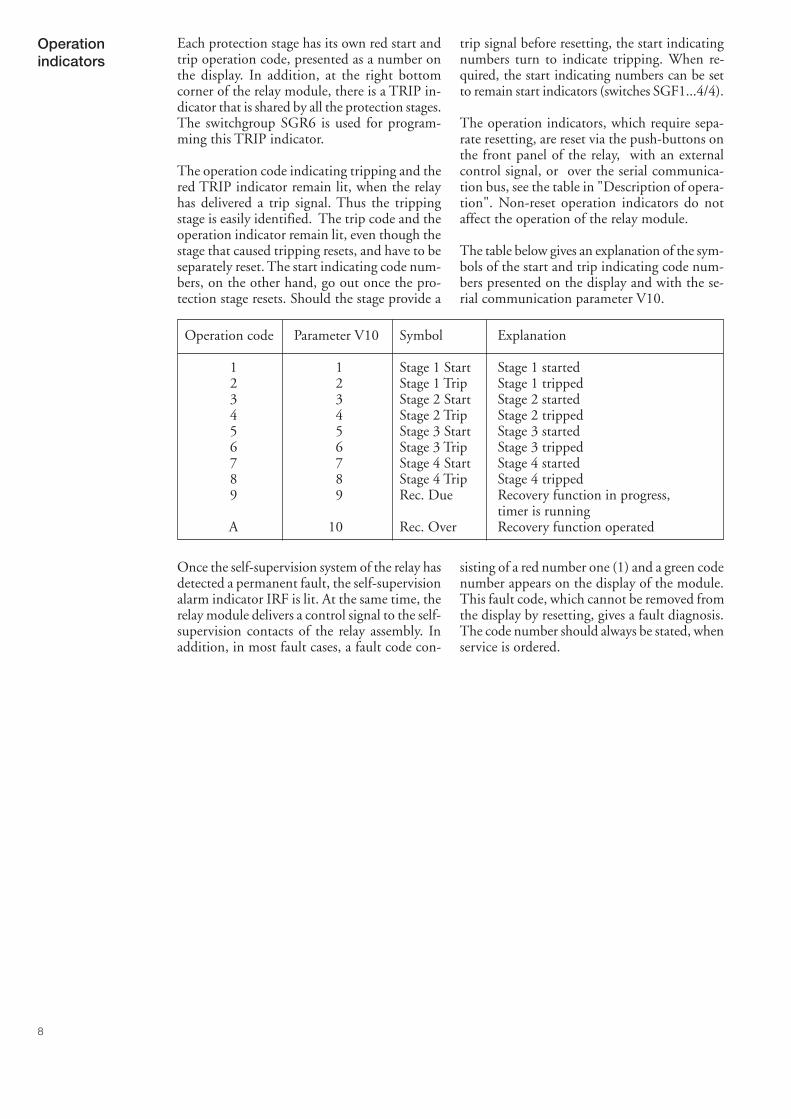
Each protection stage has its own red start andtrip operation code, presented as a number onthe display. In addition, at the right bottomcorner of the relay module, there is a TRIP in-dicator that is shared by all the protection stages.The switchgroup SGR6 is used for program-ming this TRIP indicator.
The operation code indicating tripping and thered TRIP indicator remain lit, when the relayhas delivered a trip signal. Thus the trippingstage is easily identified. The trip code and theoperation indicator remain lit, even though thestage that caused tripping resets, and have to beseparately reset. The start indicating code num-bers, on the other hand, go out once the pro-tection stage resets. Should the stage provide a
trip signal before resetting, the start indicatingnumbers turn to indicate tripping. When re-quired, the start indicating numbers can be setto remain start indicators (switches SGF1...4/4).
The operation indicators, which require sepa-rate resetting, are reset via the push-buttons onthe front panel of the relay, with an externalcontrol signal, or over the serial communica-tion bus, see the table in "Description of opera-tion". Non-reset operation indicators do notaffect the operation of the relay module.
The table below gives an explanation of the sym-bols of the start and trip indicating code num-bers presented on the display and with the se-rial communication parameter V10.
Operation code Parameter V10 Symbol Explanation
1 1 Stage 1 Start Stage 1 started2 2 Stage 1 Trip Stage 1 tripped3 3 Stage 2 Start Stage 2 started4 4 Stage 2 Trip Stage 2 tripped5 5 Stage 3 Start Stage 3 started6 6 Stage 3 Trip Stage 3 tripped7 7 Stage 4 Start Stage 4 started8 8 Stage 4 Trip Stage 4 tripped9 9 Rec. Due Recovery function in progress,
timer is runningA 10 Rec. Over Recovery function operated
Once the self-supervision system of the relay hasdetected a permanent fault, the self-supervisionalarm indicator IRF is lit. At the same time, therelay module delivers a control signal to the self-supervision contacts of the relay assembly. Inaddition, in most fault cases, a fault code con-
sisting of a red number one (1) and a green codenumber appears on the display of the module.This fault code, which cannot be removed fromthe display by resetting, gives a fault diagnosis.The code number should always be stated, whenservice is ordered.

9
Settings(modified 2004-03)
The setting values are indicated by the threedigits to the right on the display. A LED indi-cator in front of the setting value symbol on thefront panel indicates the setting value displayed
at the moment. The factory setting is given inbrackets. The symbol "//" indicates that the set-ting is found in a submenu.
Setting Description Setting range(Factory setting)
fn [Hz] Rated frequency 30.00...65.00 Hz(50 Hz)
//Number of cycles to be used in frequency measurement 3...20(6 cycles)
U</Un Setting value of undervoltage blocking as a multiple of 0.30...0.90 x Unthe rated voltage Un used. (0.60 x Un)
f1 [Hz] Setting value and operate times of stage 1 25.00...70.00 Hz(51.00 Hz)
t1 [s] 0.1...300 s (0.50 s) *)t'1 [s] 0.1...300 s (0.15 s) *)
f2 [Hz] Setting value and operate times of stage 2 25.00...70.00 Hz(49.00 Hz)
t2 [s] 0.1...300 s (1.00 s) *)t'2 [s] 0.1...300 s (0.15 s) *)
f3 [Hz] Setting value and operate times of stage 3 25.00...70.00 Hz(48.00 Hz)
t3 [s] 0.1...300 s (20.00 s) *)t'3 [s] 0.1...300 s (0.15 s) *)
f4 [Hz] Setting value and operate times of stage 4 25.00...70.00 Hz(47.00 Hz)
t4 [s] 0.1...300 s (1.00 s) *)t'4 [s] 0.1...300 s (0.15 s) *)
Idf/dt df/dt setting values for all of the four stages 0.2 ...±10.0 Hz/s[Hz/s] (1.0 Hz/s)
fr [Hz] Setting value and operate time of recovery function 0.10...10 Hz (0.20 Hz)tr [s] (10 min)
*) Note!The setting of operation time t1…t4 and t'1…t'4 = 0.10…300 s is available from program versionSW 131 F and later.

10
Configurationswitches
The switches SGF1...7, SGB1...6 and SGR1...9are used for selecting additional functions re-quired for a specific application. The numbersof the switches, 1…8, and the positions, 0 and1, are indicated on the display during the set-ting procedure. In normal service, only thechecksums of the switchgroups are indicated on
the display. The checksums are found in themain menu of the relay modules, see "Menuchart". The tables also show the factory settingsof the switches and the checksum ∑ of the fac-tory setting. The calculation of the checksum isdescribed in the end of this paragraph.
SwitchgroupsSGF1…4 Switch Function Factory
setting
SGF1...4/1 Frequency function alone is used 1
SGF1...4/2 Both frequency and df/dt function in use 0
SGF1...4/3 The df/dt function alone is used 0
SGF1...4/4 Operation mode for the start indicating codes of the separate 0protection stages.When the switch is in position 0, the start indicating operationcode is automatically reset when the fault disappears.When the switch is in position 1, the code remains lit, eventhough the fault disappears.
SGF1…4/5-8 Not in use 0
∑ SGF1 1
Switchgroup SGF5(modified 97-01)
The switches of switchgroup SGF5 are used forselecting the operation mode of the output sig-nals SS1...SS4 and TS1...TS4. When the switchis in the position 1, a control signal is continu-ously applied to the output. This means thatthe output is active as long as the stage that con-
trols it is active. When, on the other hand, theswitch is in position 0, the output is active onlyas long as the preset pulse is present. When thepulse disappears, the output resets, even thoughthe stage that controls it remains active.
Switch Function Factorysetting
SGF5/1 Continuously activated/pulse-mode output, signal SS1 1
SGF5/2 Continuously activated/pulse-mode output, signal TS1 1
SGF5/3 Continuously activated/pulse-mode output, signal SS2 1
SGF5/4 Continuously activated/pulse-mode output, signal TS2 1
SGF5/5 Continuously activated/pulse-mode output, signal SS3 1
SGF5/6 Continuously activated/pulse-mode output, signal TS3 1
SGF5/7 Continuously activated/pulse-mode output, signal SS4 1
SGF5/8 Continuously activated/pulse-mode output, signal TS4 1
∑SGF5 255

11
Switchgroup SGF6 Selection of the output signal controlling theTRIP indicator on the front panel. When theswitch linked to a certain signal is in position 1,the TRIP indicator is lit once the signal is acti-
vated. At the same time the concerned signalstarts the recovery function, provided the recov-ery output is in use (selected with SGR9/_ ).
Switch Function Factorysetting
SGF6/1 The SS1 signal activates the TRIP indicator and starts the recovery 0function.
SGF6/2 The TS1 signal activates the TRIP indicator and starts the recovery 1function.
SGF6/3 The SS2 signal activates the TRIP indicator and starts the recovery 0function.
SGF6/4 The TS2 signal activates the TRIP indicator and starts the recovery 1function.
SGF6/5 The SS3 signal activates the TRIP indicator and starts the recovery 0function.
SGF6/6 The TS3 signal activates the TRIP indicator and starts the recovery 0function.
SGF6/7 The SS4 signal activates the TRIP indicator and starts the recovery 0function.
SGF6/8 The TS4 signal activates the TRIP indicator and starts the recovery 0function.
∑ SGF6 10
Switchgroup SGF7 The switchgroup SGF7 is used for selecting therated voltage of the relay module.
Switch Rated voltage Factory100 V 110 V 115 V 120 V setting
SGF7/1 0 1 0 1 0SGF7/2 0 0 1 1 0
SGF7/3 When the switch is in position 1, 0the selected rated voltage is divided by √3.Then the following voltages are received:
57.7 V 63.5 V 66.4 V 69.3 V
SGF7/4...8 Not in use 0
∑ SGF7 0

12
SwitchgroupsSGB1...6
The switchgroups SGB1...6 are used for confi-guring the control signals BS1…BS5. The ma-trix below can be used for the programming.The control signals and the desired functionsare linked to each other, for instance, by circlingthe intersection of the lines. Each intersection
is marked with the number of the switch to beused and the weighting factor of the switch isgiven under the matrix. By adding the weight-ing factors of the switches selected in eachswitchgroup, the checksums shown to the rightof the matrix are received.
Fig. 4. Control signal matrix for relay module SPCF 1D15
Switch Function Factorysetting
SGB_/1...4 Blockings to be applied to the separate protection stages usingcontrol signals BS1...BS6.When a switch is in position 1, tripping by the concerned protectionstage will be blocked, when the control signal is activated.
SGB_/5 Blockings to be applied to the recovery stage using control signalsBS1...BS6
SGB_/6 Switching between main settings and second settings
If an external control input is used, the main setting values are activewhen no control voltage is applied to the input, whereas the secondsetting values are active, when the control input is energized.
SGB_/7 Resetting of front panel operation indicator
SGB_/8 Resetting of front panel operation indicator and registers
∑ SGB1 1∑ SGB2 2∑ SGB3 4∑ SGB4 8∑ SGB5 0∑ SGB6 15
BS1 1
t1 t1' t2 t2' t3 t3' t4 t4'
BS2 1
BS3 1
BS4 1
BS5 1
1
1
2 3 4 5
2
2
2
2
2
2
3
3
3
3
3
4
4
4
4
4
4
8
6
5
5
5
5
5
16
6
6
6
6
6
32
7
64 128
8
7 8
7 8
7 8
7 8
7 8
Σ SGB1=(Σ=1)
Σ SGB2=(Σ=2)
Σ SGB3=(Σ=4)
Σ SGB4=(Σ=8)
Σ SGB5=(Σ=0)
Σ SGB6=(Σ=15)
undervoltageblocking
weightingvalue
Checksum(Default setting)
main
secondindicators indicators
registersrecoveryfunction

13
SwitchgroupsSGR1...9
The switchgroups SGR1...9 serve for con-figuring the start and trip signals of the protec-tion stages as desired output signals SS1...SS4or TS1...TS4.
The matrix below can be used for the program-ming. The start and trip signals are linked tothe desired output signal SS1...SS4 or TS1...
TS4, for example, by circling the intersectionof the signal lines. Each intersection is markedwith the number of the switch to be used andthe weighting factor of the switch is given un-der the matrix. By adding the weighting factorsof the switches selected in each switchgroup, thechecksums shown to the right of the matrix arereceived.
SGR1 t1
t1'
t2
t2'
t3
t3'
t4
t4'
1
1
1
1
1
1
1
2 3 4 5
2
2
2
2
2
2
3
3
3
3
3
4
4
4
4
4
4
8
6
5
5
5
5
5
16
6
6
6
6
6
32
7
64 128
8
7 8
7 8
7 8
7 8
7 8
Σ SGR1=(Σ=2)
Σ SGR2=(Σ=0)
Σ SGR3=(Σ=1)
Σ SGR4=(Σ=0)
Σ SGR5=(Σ=8)
Σ SGR6=(Σ=0)
1 2 3 4 5 6 7 8Σ SGR7=(Σ=8)
1 2 3 4 5 6 7 8Σ SGR8=(Σ=0)
1 2 3 4 5 6 7 8Σ SGR9=(Σ=0)
SS1 TS1 SS2 TS2 SS3 TS3 SS4 TS4
SGR2
SGR3
SGR4
SGR5
SGR6
SGR7
SGR8
SGR9
output signal
operation stageswitch-group
recoveryfunction
Checksum(Default setting)
weighting factor
Fig. 5. Output relay matrix for relay module SPCF 1D15.
Example ofchecksumcalculation
Switch Weighting factor Position Value
SGF1/1 1 x 1 = 1SGF1/2 2 x 0 = 0SGF1/3 4 x 1 = 4SGF1/4 8 x 0 = 0SGF1/5 16 x 0 = 0SGF1/6 32 x 0 = 0SGF1/7 64 x 1 = 64SGF1/8 128 x 0 = 0
Checksum ∑ of switchgroup SGF1 69

14
Measured data The values measured are indicated by the threegreen digits to the right. An exception, how-ever, is the measured frequency, for the indica-tion of which all of the four digits of the display
can be used, see "Menu chart". The measuredvalue being presented on the display is indicatedby the yellow LEDs above the display.
LED indicator Measured data Measuring range
U Measured phase-to-phase voltage U12 as a multiple of 0.0...1.40 x Unthe rated voltage Un of the energizing input used.
f Frequency of the phase-to-phase voltage U12 20.00...75.00 Hz
Recorded data(modified 2002-06)
The left-most number of the display shows theregister address and the other three numbers the
value recorded. The structure of the registers ispresented in the section "Menu chart".
Register/ Recorded informationSTEP
1 The measured phase-to-phase voltage U12 as a multiple of the rated voltage Un.The register is updated once a protection stage trips. Then the previous values aremoved one step forward in the memory stack, the oldest value being lost. The fivelatest values are stored in the memory: the most recent value in the main registerand the other four values in the subregisters.
2 Register 2 records the frequency measured. The function of the register is the sameas that of register 1.
3 Register 3 records the rate of change of frequency measured. The function is thesame as that of register 1.
4 Register 4 records the maximum and minimum frequency and rate of change offrequency. The maximum rate of change of frequency is the maximum positivederivative of the frequency. Correspondingly, the minimum rate of change of fre-quency is the maximum negative derivative of the frequency.
The order of the register is: fmin, dfmin/dt, fmax and dfmax/dt.
5 Register 5 records the number of the stage that performed tripping and the timerfrom which tripping originated. The stages are numbered from 1 to 4 and thetimers from 1 to 2, so possible values will be 0, 11, 12, 21, 22, 31, 32, 41 and 42.The function of the register is the same as that of register 1.
6 Start counters for stages 1...4.
0 Display of external control inputs.The number to the right on the display indicates the status of the external controlsignals of the relay module. Each control signal has its own weighting factor. Thenumber indicated on the display is the added weighting values of the active signalsas follows:
Weighting Active signalvalue BS1 BS2 BS3 BS4 BS5
01 x2 x4 x8 x
16 x

15
Register/ Recorded informationSTEP
The switchgroups SGB1...5 are used for configuring the external control inputs.
From this register the TEST mode can be entered. In the TEST mode the tripsignals can be activated one by one. The table below shows the signal to be activatedplus the corresponding LED indicator.
LED indicator Signal to be activated
fn [Hz] Stage 1, output t1U</Un Stage 1, output t1'f1 [Hz] Stage 2, output t2t1 [s]f2 [Hz] Stage 2, output t2't2 [s]f3 [Hz] Stage 3, output t3t3 [s]f4 [Hz] Stage 3, output t3't4 [s]Idf/dtI [Hz/s] Stage 4, output t4fr [Hz] Stage 4, output t4'tr [s]SGF Output of recovery stage
The function is described in detail in "General characteristics of D type relay modules".
A Address code of the relay module, required for serial communication. Register Aincludes the following subregisters:1. Setting of the data transfer rate of the relay module: 4.8 or 9.6 kBd. Default
setting: 9.6 kBd.2. Bus traffic monitor. If the relay module is connected to a data communication
system and the data communication operates correctly, the value of the monitoris 0. Otherwise the numbers 0...255 are rolling.
3. Password required for remote setting. The password (parameter V160) shouldalways be entered before a setting value can be changed over the serial bus.
4. Selection of main or second settings (0 = main settings, 1 = second settings).Default setting: 0.
When the display is dark, access to the begin-ning of the main menu is admitted by pressingthe STEP button for 1 s, and to the end of themenu, by pressing the STEP button for less than0.5 s.
The values recorded in registers 1...6 can be re-set via the push-buttons on the front panel, anexternal control signal, or a serial communica-tion parameter, see "Resetting" in the section
"Description of operation". In addition, the re-gisters are cleared by an auxiliary power supplyfailure. The setting values, the address code, thedata transfer rate and the password of the relaymodule are stored in a non-volatile memory and,consequently, not affected by voltage supply fail-ures. Instructions for setting the address codeand data transfer rate are given in "General char-acteristics of D type relay modules".

16
Menu chart(modified 97-01)
Fig. 6. Menu chart for relay module SPCF 1D15
Recovery operationdelay tr [min]
Recovery operationdelay tr [s]
Main menu Submenu
STEP 0,5 s PROGRAM 1 s
Submenustep backwards STEP 0.5 s step forwards STEP 1 s
Main
menu
step
backwards
STEP
0.5s
step
forwards
STEP
1s
=value that can be set in the setting mode
Normal status, display off
Phase voltage U
Network frequency f
Protection stage 1coarse frequency setting f1
Undervoltage blocking U<
Rated frequency fn
Protection stage 2coarse frequency setting f2
Protection stage 2coarse frequency setting f2
Protection stage 4coarse frequency setting f4
Protection stage 1setting |df/dt|
Recovery window fr
Setting of relayswitchgroup SGF11
4-digit network frequency f
Setting of relayswitchgroup SGB11
Setting of relayswitchgroup SGR11
Latest memorized event (n)value of voltage U1
Latest memorized event (n)value of frequency f2
Latest memorized event (n)value of |df/dt|3
Minimum detected valueof frequency f4
Number of stage thatcaused the event (n)5
Stage 1 starting counter6
Status of externalcontrol signals0
Relay unit identificationaddress for communicationA
Number of cycles used infrequency calculation1
Protection stage 1fine frequency setting f11
Protection stage 1operation delay t12
Protection stage 2fine frequency setting f21
Protection stage 2operation delay t22
Protection stage 3fine frequency setting f31
Protection stage 3operation delay t32
Protection stage 4fine frequency setting f41
Protection stage 4operation delay t42
Protection stage 2setting |df/dt|1
Protection stage 3setting |df/dt|2
1
Setting of relayswitchgroup SGF33
Setting of relayswitchgroup SGF22
Setting of relayswitchgroup SGF66
Setting of relayswitchgroup SGF55
Setting of relayswitchgroup SGB33
Setting of relayswitchgroup SGB22
Setting of relayswitchgroup SGB66
Setting of relayswitchgroup SGB55
Setting of relayswitchgroup SGR33
Setting of relayswitchgroup SGR22
Setting of relayswitchgroup SGR77
Setting of relayswitchgroup SGR66
Event (n-1) value of voltage U1 Event (n-2) value of voltage U2
Event (n-1) value of frequency f1 Event (n-2) value of frequency f2
Event (n-1) value of |df/dt|1 Event (n-2) value of |df/dt|2
Minimum detected valueof |df/dt|1
Maximum detected valueof frequency f2
Number of stage thatcaused the event (n-1)1
Number of stage thatcaused the event (n-2)2
Stage 2 starting counter1 Stage 3 starting counter2
Loss of bus traffic timecounter 0 ... 255 s2Communication baud rate1
0 000 IRF t1 t2 t3 t4t1' t2' t3' t4' Recovery
2

17
The procedure for entering a submenu or a set-ting mode, the configuration of the module andthe use of the TEST mode are described in de-
tail in "General characteristics of D type relaymodules". Below a short guide:
Desired step or function Push-button Action
One step forward in main menu or submenu STEP Press for more than 0.5 sRapid browse forward in main menu STEP Keep depressedOne step backward in main menu or submenu STEP Press less than 0.5 sEntering a submenu from the main menu PROGRAM Press for 1 s (activated when
the button is released)Entering or quitting a setting mode PROGRAM Press for 5 sIncrementing a value in the setting mode STEPMoving the cursor in the setting mode PROGRAM Press for 1 sStoring a setting value in the setting mode STEP & PROGRAM Press simultaneouslyResetting of memorized values STEP & PROGRAM
Protection stage 1operation delay t1'3
Protection stage 2operation delay t2'3
Protection stage 3operation delay t3'3
Protection stage 4operation delay t4'3
Protection stage 4setting |df/dt|3
Setting of relayswitchgroup SGF44
Setting of relayswitchgroup SGF77
Setting of relayswitchgroup SGB44
Setting of relayswitchgroup SGR44
Setting of relayswitchgroup SGR88
Setting of relayswitchgroup SGR55
Setting of relayswitchgroup SGR99
Event (n-3) value of voltage U3 Event (n-4) value of voltage U4
Event (n-3) value of frequency f3 Event (n-4) value of frequency f4
Event (n-3) value of |df/dt|3 Event (n-4) value of |df/dt|4
Maximum detected valueof |df/dt|3
Number of stage thatcaused the event (n-3)3
Number of stage thatcaused the event (n-4)4
Stage 4 starting counter3
Password for altering settings3Selection of main vssecond setting4

18
Technical data(modified 2004-03)
Frequency functionRated frequency 30.00...65.00 HzMeasuring range 20.00...75.00 HzSetting range 25.00...70.00 HzNumber of cycles to be used for frequency measurement 3...20 cyclesOperation accuracy ±10 mHzMinimum voltage to be measured 0.25 x Un
Rate of change of frequency functionSetting range 0.2...10.0 Hz/sOperation accuracy ±150 mHz/s
Timer functionSetting range *) 0.1...300.0 sOperate time accuracy ±1% or ±30 ms
Undervoltage blockingMeasuring range 0...1.40 x UnSetting range 0,30...0.90 x UnOperation accuracy (in the range 25...70 Hz) ±3% of setting value
Recovery functionSetting range (max. deviation from rated frequency) 0.1...10.0 HzOperate time 1 s...120 min 59 sOperate time accuracy ±1% or ±30 ms
*) The minimum operate time depends on the rated frequency and the number of cycles to beused in the frequency measurement. See frequency measurement in "Description of operation".

19
Serialcommunicationparameters
Event codes
Event codes have been defined for starting andtripping of the separate protection stages andfor the output signal states. The event codes canbe transmitted to higher system levels over the
serial bus. An event to be communicated ismarked with the factor 1. An event mask isformed by adding the weighting factors of theevents communicated.
Event mask Codes Setting range Factory setting
V153 E1...E6 0...63 21V154 E7...E12 0...63 21V155 E13...E18 0...63 21V156 E19...E24 0...63 21V157 E25...E32 0...255 85V158 E33...E40 0...255 85V159 E41...E45 0...31 11
Event codes of protection relay module SPAF 1D15:
Code Event No. represent- Factorying the event setting
E1 Starting of stage 1 1 1E2 Resetting of stage 1 2 0E3 Tripping of stage 1, timer 1 4 1E4 Tripping of stage 1 (timer 1) reset 8 0E5 Tripping of stage 1, timer 2 16 1E6 Tripping of stage 1 (timer 2) reset 32 0
Event mask V153, factory setting 21
E7 Starting of stage 2 1 1E8 Resetting of stage 2 2 0E9 Tripping of stage 2, timer 1 4 1E10 Tripping of stage 2 (timer 1) reset 8 0E11 Tripping of stage 2, timer 2 16 1E12 Tripping of stage 2 (timer 2) reset 32 0
Event mask V154, factory setting 21
E13 Starting of stage 3 1 1E14 Resetting of stage 3 2 0E15 Tripping of stage 3, timer 1 4 1E16 Tripping of stage 3 (timer 1) reset 8 0E17 Tripping of stage 3, timer 2 16 1E18 Tripping of stage 3 (timer 2) reset 32 0
Event mask V155, factory setting 21
E19 Starting of stage 4 1 1E20 Resetting of stage 4 2 0E21 Tripping of stage 4, timer 1 4 1E22 Tripping of stage 4 (timer 1) reset 8 0E23 Tripping of stage 4, timer 2 16 1E24 Tripping of stage 4 (timer 2) reset 32 0
Event mask V156, factory setting 21

20
Code Event No. represent- Factorying the event setting
E25 Output signal SS1 activated 1 1E26 Output signal SS1 reset 2 0E27 Output signal SS2 activated 4 1E28 Output signal SS2 reset 8 0E29 Output signal SS3 activated 16 1E30 Output signal SS3 reset 32 0E31 Output signal SS4 activated 64 1E32 Output signal SS4 reset 128 0
Event mask V157, factory setting 85
E33 Output signal TS1 activated 1 1E34 Output signal TS1 reset 2 0E35 Output signal TS2 activated 4 1E36 Output signal TS2 reset 8 0E37 Output signal TS3 activated 16 1E38 Output signal TS3 reset 32 0E39 Output signal TS4 activated 64 1E40 Output signal TS4 reset 128 0
Event mask V158, factory setting 85
E41 Recovery function in progress 1 1E42 Recovery function stops 2 1E43 Recovery function interrupted 4 0E44 Recovery function output operates 8 1E45 Recovery function output resets 16 0
Event mask V159, factory setting 11
E50 Restart of microprocessor * -E51 Overflow of event register * -E52 Temporary disturbance in data communication * -E53 No response from the module over the data * -
communicationE54 Module responds again over the data communication * -
Explanation0 Not included in event reporting1 Included in event reporting* No code number, always communicated- cannot be programmed
The codes E50...E54 and the events representedby these cannot be excluded from event report-ing.
The event codes E52...E54 are generated by acontrol data communicator (for instance SRIO1000M)

21
Remote transfer data(modified 2004-03)
In addition to the event codes, input data (Idata), output data (O data), setting values (Sdata) memorized data (V data), and some otherdata can be read from the module over the se-rial bus. The values of parameters marked with"W" can be changed over the SPA bus.
When a setting value is to be changed, eithervia the push-buttons on the front panel or overthe serial bus, the relay module checks whetherthe given parameter value is legal. A value out-side the permitted setting range will be ignored,in which case the old setting will be retained.
To change a setting parameter over the serialbus a password in the range 1- 999 will gener-ally be needed. The factory setting is 1.
The password is opened by giving the serial com-munication parameter V160 a numerical value.The parameter V161 is used for closing the pass-word. The password is also closed by a power
supply failure.
The push-buttons of the relay module or a com-mand given over the serial bus can be used forchanging the password. To be able to changethe password over the serial bus, the passwordfirst has to be opened. The new password is en-tered using the parameter V161. When thepush-buttons are used for changing the pass-word, the new password is written over the oldone in subregister 3 of register A.
Should the wrong password be given seven timesin succession, the password turns into zero andcan no longer be opened over the serial bus.Then it can be given a new value only using thepush-buttons.
R = data to be read from the moduleW = data to be written to the module(P) = writing enabled through a password
The parameters I1...I4 can be used for readingmeasured values (R) and status data of externalcontrol signals.
Input data
Data Parameter Values
Phase-to-phase voltage U12 I1 0.00...1.4 x UnNetwork frequency I2 20.00...75.00 HzRate of change of frequency df/dt I3 -10.0...+10.0 Hz/sExternal control signals BS1...BS5 I4 0...31
Variable value explained in"Recorded information"

22
Outputs Status data of protection stages
Protection stage/operation Parameter (R) Weighting factor
Frequency function of stage 1 started O1 1Stage 1 tripped, operate time t1’ 2Stage 1 tripped, operate time t1 4df/dt function of stage 1 started 8
Frequency function of stage 2 started O2 1Stage 2 tripped, operate time t2’ 2Stage 2 tripped, operate time t2 4df/dt function of stage 2 started 8
Frequency function of stage 3 started O3 1Stage 3 tripped, operate time t3’ 2Stage 3 tripped, operate time t3 4df/dt function of stage 3 started 8
Frequency function of stage 4 started O4 1Stage 4 tripped, operate time t4’ 2Stage 4 tripped, operate time t4 4df/dt function of stage 4 started 8
Recovery function started, timer is running O5 1Recovery function operated 2Undervoltage blocking 4
Output signals
Output signal O6 (R,W,P) Weighting factor
Output signal SS1 1Output signal TS1 2Output signal SS2 4Output signal TS2 8Output signal SS3 16Output signal TS3 32Output signal SS4 64Output signal TS4 128
Setting valuesSetting Actual Main sett. Sec. sett. Setting range
values (R) values values(R,W,P) (R,W,P)
Rated frequency fn S1 S61 S121 30.0...65.0 HzNumber of counting cycles used S2 S62 S122 3...20 cyclesUndervoltage blocking settingvalue U< S3 S63 S123 0.30...0.90 x Un
Start value f1, stage 1 S6 S66 S126 25.00...70.00 HzStart value f2, stage 2 S7 S67 S127 25.00...70.00 HzStart value f3, stage 3 S8 S68 S128 25.00...70.00 HzStart value f4, stage 4 S9 S69 S129 25.00...70.00 Hz

23
Setting Actual Main sett. Sec. sett. Setting rangevalues (R) values values(R,W,P) (R,W,P)
Operate time t1, stage 1 S10 S70 S130 0.10...300.00 s **)Operate time t'1, stage 1 S11 S71 S131 0.10...300.00 s *)Operate time t2, stage 2 S12 S72 S132 0.10...300.00 s **)Operate time t'2, stage 2 S13 S73 S133 0.10...300.00 s *)Operate time t3, stage 3 S14 S74 S134 0.10...300.00 s **)Operate time t'3, stage 3 S15 S75 S135 0.10...300.00 s *)Operate time t4, stage 4 S16 S76 S136 0.10...300.00 s **)Operate time t'4, stage 4 S17 S77 S137 0.10...300.00 s *)Start value Idf/dtI, stage 1 S18 S78 S138 0.2...10.00 Hz/sStart value Idf/dtI, stage 2 S19 S79 S139 0.2...10.00 Hz/sStart value Idf/dtI, stage 3 S20 S80 S140 0.2...10.00 Hz/sStart value Idf/dtI, stage 4 S21 S81 S141 0.2...10.00 Hz/s
Start value fr of recovery function S22 S82 S142 0.1...10.0 HzOperate time tr of recovery function S23 S83 S143 1 s...120 min 59 s
Checksum, SGF1 S24 S84 S144 0...255Checksum, SGF2 S25 S85 S145 0...255Checksum, SGF3 S26 S86 S146 0...255Checksum, SGF4 S27 S87 S147 0...255Checksum, SGF5 S28 S88 S148 0...255Checksum, SGF6 S29 S89 S149 0...255Checksum, SGF7 S30 S90 S150 0...255
Checksum, SGB1 S31 S91 S151 0...255Checksum, SGB2 S32 S92 S152 0...255Checksum, SGB3 S33 S93 S153 0...255Checksum, SGB4 S34 S94 S154 0...255Checksum, SGB5 S35 S95 S155 0...255Checksum, SGB6 S36 S96 S156 0...255
Checksum, SGR1 S37 S97 S157 0...255Checksum, SGR2 S38 S98 S158 0...255Checksum, SGR3 S39 S99 S159 0...255Checksum, SGR4 S40 S100 S160 0...255Checksum, SGR5 S41 S101 S161 0...255Checksum, SGR6 S42 S102 S162 0...255Checksum, SGR7 S43 S103 S163 0...255Checksum, SGR8 S44 S104 S164 0...255Checksum, SGR9 S45 S105 S165 0...255
Length of control pulse SS1 S46 S106 S166 0.1...20.0 sLength of control pulse TS1 S47 S107 S167 0.1...20.0 sLength of control pulse SS2 S48 S108 S168 0.1...20.0 sLength of control pulse TS2 S49 S109 S169 0.1...20.0 sLength of control pulse SS3 S50 S110 S170 0.1...20.0 sLength of control pulse TS3 S51 S111 S171 0.1...20.0 sLength of control pulse SS4 S52 S112 S172 0.1...20.0 sLength of control pulse TS4 S53 S113 S173 0.1...20.0 s
*) The minimum operate time depends on the rated frequency and the number of cycles used forthe measurement. See "Frequency measurement" in the section "Description of operation".
**) If the df/dt function is in use the setting range is 0.15...300.00 s
The setting of operation time is available from program version SW 131 F and later.

24
Measured value Code Data direction Value
Number of starts, stage 1 V1 R 0...255Number of starts, stage 2 V2 R 0...255Number of starts, stage 3 V3 R 0...255Number of starts, stage 4 V4 R 0...255Number of trips, stage 1 V5 R 0...255Number of trips, stage 2 V6 R 0...255Number of trips, stage 3 V7 R 0...255Number of trips, stage 4 V8 R 0...255
Number of recovery operations V9 R 0...255
Red operation code of display V10 R 0...10
Minimum df/dt measured V60 R 0.0...-10.0 Hz/sMinimum frequency measured V61 R 20.00...75.00 HzMaximum df/dt measured V62 R 0.0...10.0 Hz/sMaximum frequency measured V63 R 20.00...75.00 Hz
The parameters V11...V54 can be used to read(R) the five latest values recorded. Event n is
the most recent value recorded, event n-1 theprevious value, and so on.
Recorded data Event Measuring range n n-1 n-2 n-3 n-4
Voltage U V11 V21 V31 V41 V51 0.0...1.4 x UnFrequency f V12 V22 V32 V42 V52 20.00...75.00 HzFrequency rate of change lIdf/dtIl V13 V23 V33 V43 V53 0.0...±10.0 Hz/sNo. of tripped stage and output V14 V24 V34 V44 V54 0, 11, 12, 21,22,
31, 32, 41, 42 *)
*) 11 to be understood as stage 1 timer t1, 32 as stage 3 timer t3', etc.
Measured andrecorded parametervalues
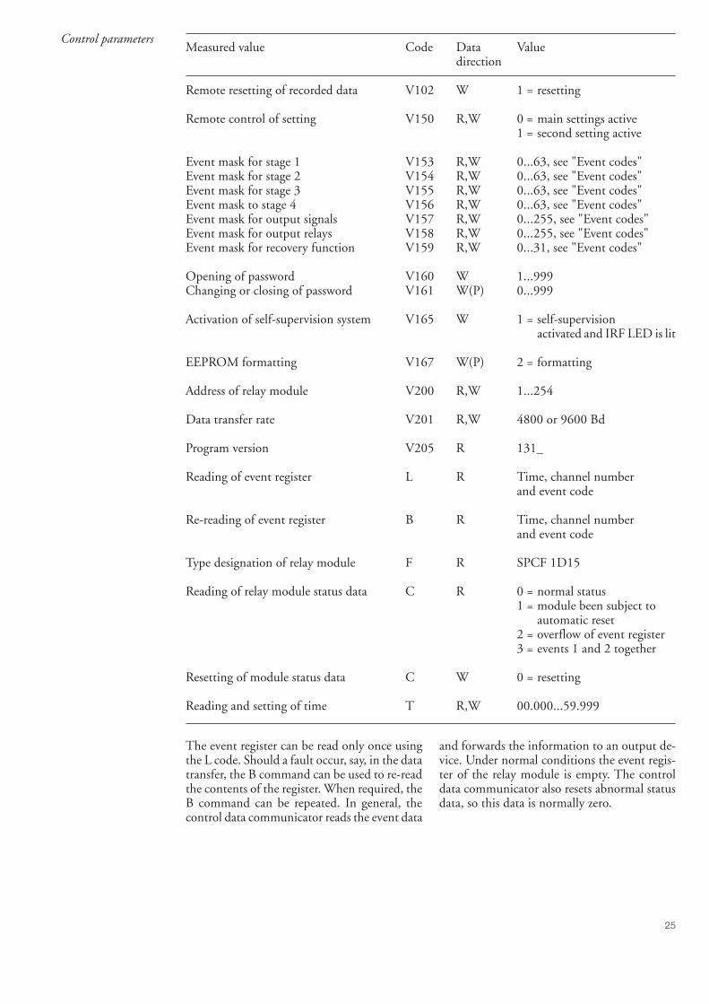
25
Measured value Code Data Valuedirection
Remote resetting of recorded data V102 W 1 = resetting
Remote control of setting V150 R,W 0 = main settings active1 = second setting active
Event mask for stage 1 V153 R,W 0...63, see "Event codes"Event mask for stage 2 V154 R,W 0...63, see "Event codes"Event mask for stage 3 V155 R,W 0...63, see "Event codes"Event mask to stage 4 V156 R,W 0...63, see "Event codes"Event mask for output signals V157 R,W 0...255, see "Event codes"Event mask for output relays V158 R,W 0...255, see "Event codes"Event mask for recovery function V159 R,W 0...31, see "Event codes"
Opening of password V160 W 1...999Changing or closing of password V161 W(P) 0...999
Activation of self-supervision system V165 W 1 = self-supervisionactivated and IRF LED is lit
EEPROM formatting V167 W(P) 2 = formatting
Address of relay module V200 R,W 1...254
Data transfer rate V201 R,W 4800 or 9600 Bd
Program version V205 R 131_
Reading of event register L R Time, channel numberand event code
Re-reading of event register B R Time, channel numberand event code
Type designation of relay module F R SPCF 1D15
Reading of relay module status data C R 0 = normal status1 = module been subject to
automatic reset2 = overflow of event register3 = events 1 and 2 together
Resetting of module status data C W 0 = resetting
Reading and setting of time T R,W 00.000...59.999
The event register can be read only once usingthe L code. Should a fault occur, say, in the datatransfer, the B command can be used to re-readthe contents of the register. When required, theB command can be repeated. In general, thecontrol data communicator reads the event data
and forwards the information to an output de-vice. Under normal conditions the event regis-ter of the relay module is empty. The controldata communicator also resets abnormal statusdata, so this data is normally zero.
Control parameters

26
Fault codes Once the self-supervision system has detected apermanent fault, the IRF indicator on the frontpanel of the module is lit and, at the same time,the normally operated signal relay of the self-supervision system drops out.
In most fault situations, a fault code consistingof a red digit one (1) to the left and a green code
number appears on the display of the relay mod-ule. The fault code indicates the fault type andcannot be reset. To facilitate maintenance andrepair it should be recorded and stated, when serv-ice is ordered.
The fault codes of the protection relay moduleSPCF 1D15 are explained in the following table:
Fault code Explanation
4 Faulty or missing control circuit30 Faulty program memory41 Half-cycle detector faulty50 Internal RAM memory faulty51 Parameter memory (EEPROM) block 1 faulty52 Parameter memory (EEPROM) block 2 faulty53 Parameter memory (EEPROM) block 1 and 2 faulty56 Parameter memory (EEPROM) key faulty. To be formatted by writing V167=2.
195 Measured value too low in reference channel203 Measured value too high in reference channel

SGR
SGB
SGF
SPCJ 4D29
TRIP
PROGRAM
RESETSTEP
L1 L2 L3 o IRF
3 >I
IIII
> nI I/
ks>t [ ]
n>>I I/
s>>[ ]t
so >ko
[ ]t
no>I I/
s>>ot [ ]
n>>o I/I
879B
IRelay symbol
Self-supervision alarm indicator(Internal Relay Fault)
Display, 1 + 3 digits
Reset / Step push-button
Programming push-button
Trip indicator
Module type designation
Fastening screw
Indicators for measuredquantities
Indicators for settingparameters
Indicators for switchgroupsSGF, SGB and SGR
Fastening screw
General characteristics ofD-type relay modules
User´s manual and Technical description

2
General characteristicsof D type relay modules
Contents Front panel lay-out ......................................................................................................... 1Control push buttons ..................................................................................................... 3Display ........................................................................................................................... 3
Display main menu ................................................................................................... 3Display submenus ..................................................................................................... 3
Selector switchgroups SGF, SGB, SGR .......................................................................... 4Settings ........................................................................................................................... 4
Setting mode ............................................................................................................. 4Example 1: Setting of relay operation values .............................................................. 7Example 2: Setting of relay switchgroups................................................................... 9
Recorded information ................................................................................................... 11Trip test function ......................................................................................................... 12
Example 3: Forced activation of outputs ................................................................. 13Operation indicators ..................................................................................................... 15Fault codes .................................................................................................................... 15
1MRS 750066-MUM EN
Issued 95-04-12Version A (replaces 34 SPC 3 EN1)Checked JHApproved TK
Data subject to change without notice

3
Controlpush-buttons
The front panel of the relay module containstwo push buttons. The RESET / STEP pushbutton is used for resetting operation indicatorsand for stepping forward or backward in thedisplay main menu or submenus. The PRO-GRAM push button is used for moving from a
certain position in the main menu to the corre-sponding submenu, for entering the settingmode of a certain parameter and together withthe STEP push button for storing the set values.The different operations are described in thesubsequent paragraphs in this manual.
Display The measured and set values and the recordeddata are shown on the display of the protectionrelay module. The display consists of four digits.The three green digits to the right show themeasured, set or recorded value and the leftmostred digit shows the code number of the register.The measured or set value displayed is indicatedby the adjacent yellow LED indicator on thefront panel. When a recorded fault value is beingdisplayed the red digit shows the number of thecorresponding register. When the display func-tions as an operation indicator the red digitalone is shown.
When the auxiliary voltage of a protection relaymodule is switched on the module initially teststhe display by stepping through all the segmentsof the display for about 15 seconds. At first thecorresponding segments of all digits are lit oneby one clockwise, including the decimal points.Then the center segment of each digit is lit oneby one. The complete sequence is carried outtwice. When the test is finished the display turnsdark. The testing can be interrupted by pressingthe STEP push button. The protection func-tions of the relay module are alerted throughoutthe testing.
Display main menu Any data required during normal operation areaccessible in the main menu i.e. present meas-ured values, present setting values and recordedparameter values.
The data to be shown in the main menu aresequentially called up for display by means ofthe STEP push button. When the STEP pushbutton is pressed for about one second, thedisplay moves forward in the display sequence.When the push button is pressed for about 0.5seconds, the display moves backward in thedisplay sequence.
From a dark display only forward movement ispossible. When the STEP push button is pushedconstantly, the display continuously moves for-ward stopping for a while in the dark position.
Unless the display is switched off by stepping tothe dark point, it remains lit for about 5 minutesfrom the moment the STEP push button waslast pushed. After the 5 minutes' time-out thedispaly is switched off.
Display submenus Less important values and values not very oftenset are displayed in the submenus. The numberof submenus varies with different relay moduletypes. The submenus are presented in the de-scription of the concerned protection relaymodule.
A submenu is entered from the main menu bypressing the PROGRAM push button for aboutone second. When the push button is released,the red digit of the display starts flashing, indi-cating that a submenu has been entered. Goingfrom one submenu to another or back to themain menu follows the same principle as whenmoving from the main menu display to another;
the display moves forward when the STEP pushbutton is pushed for one second and backwardwhen it is pushed for 0.5 seconds. The mainmenu has been re-entered when the red displayturns dark.
When a submenu is entered from a main menuof a measured or set value indicated by a LEDindicator, the indicator remains lit and the ad-dress window of the display starts flashing. Asubmenu position is indicated by a flashing redaddress number alone on the dispaly withoutany lit set value LED indicator on the frontpanel.

4
Selector switch-groups SGF, SGBand SGR
Part of the settings and the selections of theoperation characteristic of the relay modules invarious applications are made with the selectorswitchgroups SG_ . The switchgroups are soft-ware based and thus not physically to be foundin the hardware of the relay module. The indi-cator of the switchgroup is lit when the checksumof the switchgroup is shown on the display.Starting from the displayed checksum and byentering the setting mode, the switches can beset one by one as if they were real physicalswitches. At the end of the setting procedure, achecksum for the whole switchgroup is shown.The checksum can be used for verifying that theswitches have been properly set. Fig. 2 shows anexample of a manual checksum calculation.
When the checksum calculated according to theexample equals the checksum indicated on thedisplay of the relay module, the switches in theconcerned switchgroup are properly set.
Switch No Pos. Weigth Value
1 1 x 1 = 12 0 x 2 = 03 1 x 4 = 44 1 x 8 = 85 1 x 16 = 166 0 x 32 = 07 1 x 64 = 648 0 x 128 = 0
Checksum ∑ = 93
Fig. 2. Example of calculating the checksum ofa selector switchgroup SG_.
The functions of the selector switches of thedifferent protection relay modules are describedin detail in the manuals of the different relaymodules.
Settings Most of the start values and operate times are setby means of the display and the push buttons onthe front panel of the relay modules. Eachsetting has its related indicator which is lit whenthe concerned setting value is shown on thedisplay.
In addition to the main stack of setting valuesmost D type relay modules allow a second stackof settings. Switching between the main settings
and the second settings can be done in threedifferent ways:
1) By command V150 over the serial communi-cation bus
2) By an external control signal BS1, BS2 orRRES (BS3)
3) Via the push-buttons of the relay module, seesubmenu 4 of register A.
Setting mode Generally, when a large number of settings is tobe altered, e.g. during commissioning of relaysystems, it is recommended that the relay set-tings are entered with the keyboard of apersonal computer provided with the necessarysoftware. When no computer nor software isavailable or when only a few setting values needto be altered the procedure described below isused.
The registers of the main menu and the submenuscontain all parameters that can be set. Thesettings are made in the so called setting mode,which is accessible from the main menu or asubmenu by pressing the PROGRAM pushbutton, until the whole display starts flashing.This position indicates the value of the param-eter before it has been altered. By pressing thePROGRAM push button the programming se-quence moves forward one step. First therightmost digit starts flashing while the rest ofthe display is steady. The flashing digit is set bymeans of the STEP push button. The flashing
cursor is moved on from digit to digit by press-ing the PROGRAM push button and in eachstop the setting is performed with the STEPpush button. After the parameter values havebeen set, the decimal point is put in place. At theend the position with the whole display flashingis reached again and the data is ready to bestored.
A set value is recorded in the memory by press-ing the push buttons STEP and PROGRAMsimultaneously. Until the new value has beenrecorded a return from the setting mode willhave no effect on the setting and the formervalue will still be valid. Furthermore any attemptto make a setting outside the permitted limits for aparticular parameter will cause the new value to bedisqualified and the former value will be main-tained. Return from the setting mode to themain menu or a submenu is possible by pressingthe PROGRAM push button until the greendigits on the display stop flashing.

5
NOTE! During any local man-machine com-munication over the push buttons and the dis-play on the front panel a five minute time-outfunction is active. Thus, if no push button hasbeen pressed during the last five minutes, therelay returns to its normal state automatically.This means that the display turns dark, the relayescapes from a display mode, a programmingroutine or any routine going on, when the relayis left untouched. This is a convenient way outof any situation when the user does not knowwhat to do.
Before a relay module is inserted into the relaycase, one must assure that the module has beengiven the correct settings. If there however is
any doubt about the settings of the module to beinserted, the setting values should be read usinga spare relay unit or with the relay trip circuitsdisconnected. If this cannot be done the relaycan be sett into a non-tripping mode by pressingthe PROGRAM push button and powering upthe relay module simultaneously. The displaywill show three dashes "- - -" to indicate the non-tripping mode. The serial communication isoperative and all main and submenues are acces-sible. In the non-tripping mode unnecessarytrippings are avoided and the settings can bechecked. The normal protection relay mode isentered automatically after a timeout of fiveminutes or ten seconds after the dark displayposition of the main menu has been entered.
Normal status, display off
First measuring value
Last measuring value
Memorized values etc.
Actual setting value 1
SUBMENUMAIN MENU SETTING MODE
Second setting value for stage 12
1 Main setting value for stage 1
1 0 0 0
INCREASE VALUESTEP 0,5 s
MOVE FIGURE OR DECIMAL POINT CURSOR WITH BUTTON PROGRAM 1 s
STORE NEW SETTING BY PRESSING STEP AND PROGRAM SIMULTANEOUSLY WHEN THE VALUE IS READY AND THE WHOLE DISPLAY IS BLINKING
Actual setting value 2
FWD.STEP 1 s
REV. STEP 0,5 s
FWD.STEP 1 s
REV. STEP 0,5 s
NOTE! IN MOST MENU CHARTS THE SUBMENUS HAVE BEEN DRAWN IN A HORIZONTAL DIRECTION IN ORDER TO GET ALL MAIN AND SUBMENU POSITIONS SHOWN IN THE SAME CHART.
STEP 0,5 s PROGRAM 1 s PROGRAM 5 s PROGRAM 5 s
Fig.3. Basic principles of entering the main menus and submenus of a relay module.

6
Normal status, display off
Current on phase L1
Current on phase L2
Current on phase L3
Neutral current Io
Maximum demand currentvalue for 15 minutes4
Second settingvalue for t> or k
Actual operate time t> or multiplier k for stage I>
21
Second settingvalue for I>> Actual start value I>> 21
Second settingvalue for t>>
Actual operate time t>> of stage I>>
21
Second setting value for Io>
Actual start value Io> 21
Second settingvalue for to> or ko
Actual operate time to>or multiplier ko
21
Second setting value for Io>> Actual start value Io>> 21
Second setting value for to>>
Actual operate time to>> 21
Main setting of SGF1 checksum
Actual setting of functionalswitchgroup SGF1
21
Actual setting of blockingswitchgroup SGB
1 Main setting of SGB checksum
Actual setting of relayswitchgroup SGR1
1 Main setting of SGR1 checksum
2
Event (n-1) value of phase L1
Event (n-2) value of phase L1
Latest memorized, event (n)value of phase L11 1 2
Event (n-1) value of phase L2
Event (n-2) value of phase L2
Latest memorized, event (n) value of phase L22 1 2
Event (n-1) value of phase L3
Event (n-2) value of phase L3
Latest memorized, event (n)value of phase L33 1 2
Main settingvalue for t> or k
Main settingvalue for I>>
Main settingvalue for t>>
Main setting value for Io>
Main settingvalue for to> or ko
Main setting value for Io>>
Main setting value for to>>
Second setting of SGB checksum
2
Second setting value for I>
21 Main setting value for I> Actual start value I>
SUBMENUSFWD. STEP 1 sREV. STEP 0.5 s
MA IN
MENU
REV.
STEP
.5s
FWD.
STEP
1s
MAIN MENU SUBMENUS
STEP 0.5 s PROGRAM 1 s
Highest maximum demand value found
1
Main setting of SGF2 checksum
Main setting of SGR2 checksum
Fig. 4.Example of part of the main and submenus for the settings of the overcurrent and earth-faultrelay module SPCJ 4D29. The settings currently in use are in the main manu and they are displayedby pressing the STEP push button. The main menu also includes the measured current values, theregisters 1...9, 0 and A. The main and second setting values are located in the submenus and arecalled up on the display with the PROGRAM push button.

7
Example 1 Operation in the setting mode. Manual settingof the main setting of the start current value I>of an overcurrent relay module. The initial value
a)Press push button STEP repeatedly until theLED close to the I> symbol is lit and the currentstart value appears on the display.
b)Enter the submenu to get the main setting valueby pressing the PROGRAM push button morethan one second and then releasing it. The reddisplay digit now shows a flashing number 1,indicating the first submenu position and thegreen digits show the set value.
c)Enter the setting mode by pressing the PRO-GRAM push button for five seconds until thedisplay starts flashing.
d)Press the PROGRAM push button once againfor one second to get the rightmost digit flash-ing.
e)Now the flashing digit can be altered. Use theSTEP push button to set the digit to the desiredvalue.
f)Press the PROGRAM push button to make themiddle one of the green digits flash.
g)Set the middle digit with of the STEP pushbutton.
h)Press the PROGRAM push button to make theleftmost green digit flash.
for the main setting is 0.80 x In and for thesecond setting 1.00 x In. The desired main startvalue is 1.05 x In.
5 x 1 s
1 s
5 s
1 s
5 x
1 s
2 x
1 s
0. 8 0
1 0. 8 0
1 0. 8 0
1 0. 8 0
1 0. 8 5
1 0. 8 5
1 0. 0 5
1 0. 0 5
RESET STEP
PROGRAM
PROGRAM
PROGRAM
RESET STEP
RESET STEP
PROGRAM
PROGRAM

8
1 s
0 x
1 s
0 x
1 s
5 s
1 1. 0 5
1 1. 0 5
1 1. 0 5
1 1. 0 5
1 - - -
1 1. 0 5
2 1. 0 0
i)Set the digit with the STEP push button.
j)Press the PROGRAM push button to make thedecimal point flash.
k)If needed, move the decimal point with theSTEP push button.
l)Press the PROGRAM push button to make thewhole display flash. In this position, corre-sponding to position c) above, one can see thenew value before it is recorded. If the valueneeds changing, use the PROGRAM push but-ton to alter the value.
m)When the new value has been corrected, recordit in the memory of the relay module by pressingthe PROGRAM and STEP push buttons simul-taneously. At the moment the information en-ters the memory, the green dashes flash once inthe display, i.e. 1 - - -.
n)Recording of the new value automatically initi-ates a return from the setting mode to thenormal submenu. Without recording one canleave the setting mode any time by pressing thePROGRAM push button for about five sec-onds, until the green display digits stop flashing.
o)If the second setting is to be altered, entersubmenu position 2 of the setting I> by pressingthe STEP push button for approx. one second.The flashing position indicator 1 will then bereplaced by a flashing number 2 which indicatesthat the setting shown on the display is thesecond setting for I>.
Enter the setting mode as in step c) and proceedin the same way. After recording of the re-quested values return to the main menu isobtained by pressing the STEP push button
RESET STEP
PROGRAM
RESET STEP
PROGRAM
RESET STEP
PROGRAM
PROGRAM
RESET STEP
until the first digit is switched off. The LED stillshows that one is in the I> position and thedisplay shows the new setting value currently inuse by the relay module.

9
Example 2
5 s
1 x
1 s
1 x
1 s
Operation in the setting mode. Manual settingof the main setting of the checksum for theswitchgroup SGF1 of a relay module. The initialvalue for the checksum is 000 and the switches
SGF1/1and SGF1/3 are to be set in position 1.This means that a checksum of 005 should bethe final result.
n x 1 s
1 s
a)Press push button STEP until the LED close tothe SGF symbol is lit and the checksum appearson the display.
b)Enter the submenu to get the main checksum ofSGF1 by pressing the PROGRAM push buttonfor more than one second and then releasing it.The red display now shows a flashing number 1indicating the first submenu position and thegreen digits show the checksum.
c)Enter the setting mode by pressing the PRO-GRAM push button for five seconds until thedisplay starts flashing.
d)Press the PROGRAM push button once againto get the first switch position. The first digit ofthe display now shows the switch number. Theposition of the switch is shown by the rightmostdigit.
e)The switch position can now be toggled be-tween 1 and 0 by means of the STEP pushbutton and it is left in the requested position 1.
f)When switch number 1 is in the requestedposition, switch number 2 is called up by press-ing the PROGRAM push button for one sec-ond. As in step e), the switch position can bealtered by using the STEP push button. As thedesired setting for SGF1/2 is 0 the switch is leftin the 0 position.
g)Switch SGF1/3 is called up as in step f) bypressing the PROGRAM push button for aboutone second.
0 0 0
1 0 0 0
1 0 0 0
1 1 0
1 1 1
1 2 0
1 3 0
RESET STEP
PROGRAM
PROGRAM
PROGRAM
RESET STEP
PROGRAM
PROGRAM

10
1 x
n x 1 s
5 s
5 x 1 s
1 0 0 5
1 - - -
1 0 0 5
0 0 5
1 3 1h)The switch position is altered to the desiredposition 1 by pressing the STEP push buttononce.
i)Using the same procedure the switches SGF 1/4...8 are called up and, according to the exam-ple, left in position 0.
j)In the final setting mode position, correspond-ing to step c), the checksum based on the setswitch positions is shown.
k)If the correct checksum has been obtained, it isrecorded in the memory by pressing the pushbuttons PROGRAM and STEP simultaneously.At the moment the information enters thememory, the green dashes flash in the display,i.e.1 - - -. If the checksum is incorrect, thesetting of the separate switches is repeated usingthe PROGRAM and STEP push buttons start-ing from step d).
l)Recording the new value automatically initiatesa return from the setting mode to the normalmenu. Without recording one can leave thesetting mode any time by pressing the PRO-GRAM push button for about five seconds,until the green display digits stop flashing.
m)After recording the desired values return to themain menu is obtained by pressing the STEPpush button until the first digit is turned off.The LED indicator SGF still shows that one isin the SGF position and that the display showsthe new checksum for SGF1 currently in use bythe relay module.
RESET STEP
PROGRAM
RESET STEP
PROGRAM
PROGRAM
RESET STEP

11
Recordedinformation
The parameter values measured at the momentwhen a fault occurs or at the trip instant arerecorded in the registers. The recorded data,except for some parameters, are set to zero bypressing the push buttons STEP and PRO-GRAM simultaneously. The data in normalregisters are erased if the auxiliary voltage supplyto the relay is interrupted, only the set values andcertain other essential parameters are maintainedin non-volatile registers during a voltage failure.
The number of registers varies with differentrelay module types. The functions of the regis-ters are illustrated in the descriptions of thedifferent relay modules. Additionally, the sys-tem front panel of the relay contains a simplifiedlist of the data recorded by the various relaymodules of the protection relay.
All D type relay modules are provided with twogeneral registers: register 0 and register A.
Register 0 contains, in coded form, the informa-tion about e.g. external blocking signals, statusinformation and other signals. The codes areexplained in the manuals of the different relaymodules.
Register A contains the address code of the relaymodul which is reqiured by the serial communi-cation system.
Submenu 1 of register A contains the data trans-fer rate value, expressed in kilobaud, of the serialcommunication.
Submenu 2 of register A contains a bus commu-nication monitor for the SPAbus. If the protec-tion relay, which contains the relay module, islinked to a system including a contol datacommunicatoe, for instance SRIO 1000M andthe data communication system is operating,the counter reading of the monitor will be zero.Otherwise the digits 1...255 are continuouslyscrolling in the monitor.
Submenu 3 contains the password required forchanging the remote settings. The address code,the data transfer rate of the serial communica-tion and the password can be set manually or viathe serial communication bus. For manual set-ting see example 1.
The default value is 001 for the address code, 9.6kilobaud for the data transfer rate and 001 forthe password.
In order to secure the setting values, all settingsare recorded in two separate memory bankswithin the non-volatile memory. Each bank iscomplete with its own checksum test to verifythe condition of the memory contents. If, forsome reason, the contents of one bank isdisturbed, all settings are taken from the otherbank and the contents from here is transferred tothe faulty memory region, all while the relay isin full operation condition. If both memorybanks are simultaneously damaged the relay willbe be set out of operation, and an alarm signalwill be given over the serial port and the IRFoutput relay

12
Trip test function Register 0 also provides access to a trip testfunction, which allows the output signals of therelay module to be activated one by one. If theauxiliary relay module of the protection assem-bly is in place, the auxiliary relays then willoperate one by one during the testing.
When pressing the PROGRAM push buttonfor about five seconds, the green digits to theright start flashing indicating that the relaymodule is in the test position. The indicators ofthe settings indicate by flashing which outputsignal can be activated. The required outputfunction is selected by pressing the PROGRAMpush button for about one second.
The indicators of the setting quantities refer tothe following output signals:
Setting I> Starting of stage I>Setting t> Tripping of stage I>Setting I>> Starting of stage I>>Setting t>> Tripping of stage I>>etc.No indication Self-supervision IRF
The selected starting or tripping is activated bysimultaneous pressing of the push buttonsSTEP and PROGRAM. The signal remainsactivated as long as the two push butttons arepressed. The effect on the output relays dependson the configuration of the output relay matrixswitches.
The self-supervision output is activated by press-ing the STEP push button 1 second when nosetting indicator is flashing. The IRF output isactivated in about 1 second after pressing of theSTEP push button.
The signals are selected in the order illustrated inFig. 4.
REGISTER 0I> START I> TRIP I» START I» TRIP Io> START Io> TRIP Io»START Io» TRIP
PROGRAM 5 s
PROGRAM 1 s
PROGRAM 1 s
PROGRAM 1 s
PROGRAM 1 s
PROGRAM 1 s
PROGRAM 1 s
PROGRAM 1 s
PROGRAM 1 s
STEP &PROGRAM
STEP &PROGRAM
STEP &PROGRAM
STEP &PROGRAM
STEP &PROGRAM
STEP &PROGRAM
STEP &PROGRAM
STEP &PROGRAM
I»t»
I>t>
Io> to>Io»
to»
IRF
STEP
PROGRAM 1 s
Fig. 5.Sequence order for the selection of output signals in the Trip test mode
If, for instance, the indicator of the setting t> isflashing, and the push buttons STEP and PRO-GRAM are being pressed, the trip signal fromthe low-set overcurrent stage is activated. Re-turn to the main menu is possible at any stage ofthe trip test sequence scheme, by pressing thePROGRAM push button for about five sec-onds.
Note!The effect on the output relays then depends onthe configuration of the output relay matrixswitchgroups SGR 1...3.

13
SGR
SGB
SGF
SPCJ 4D29
TRIP
PROGRAM
RESETSTEP
L1 L2 L3 o IRF
3 >I
IIII
> nI I/
ks>t [ ]
n>>I I/
s>>[ ]t
so >ko
[ ]t
no>I I/
s>>ot [ ]
n>>o I/I
879B
I
Example 3
n x 1 s
0 0 0 0
5 s0 0 0 0
Trip test function. Forced activation of theoutputs.
a)Step forward on the display to register 0.
b)Press the PROGRAM push button for aboutfive seconds until the three green digits to theright.
c)Hold down the STEP push button. After onesecond the red IRF indicator is lit and the IRFoutput is activated. When the step push buttonis released the IRF indicator is switched off andthe IRF output resets.
d)Press the PROGRAM push button for onesecond and the indicator of the topmost settingstart flashing.
e)If a start of the first stage is required, now pressthe push-buttons PROGRAM and STEP simul-taneously. The stage output will be activated andthe output relays will operate according to theactual programming of the relay outputswitchgroups SGR.
0 0 0 0
RESET STEP
PROGRAM
RESET STEP
PROGRAM
SGR
SGB
SGF
SPCJ 4D29
TRIP
PROGRAM
RESETSTEP
L1 L2 L3 o IRF
3 >I
IIII
> nI I/
ks>t [ ]
n>>I I/
s>>[ ]t
so >ko
[ ]t
no>I I/
s>>ot [ ]
n>>o I/I
879B
I

14
SGR
SGB
SGF
SPCJ 4D29
TRIP
PROGRAM
RESETSTEP
L1 L2 L3 o IRF
3 >I
IIII
> nI I/
ks>t [ ]
n>>I I/
s>>[ ]t
so >ko
[ ]t
no>I I/
s>>ot [ ]
n>>o I/I
879B
I
SGR
SGB
SGF
SPCJ 4D29
TRIP
PROGRAM
RESETSTEP
L1 L2 L3 o IRF
3 >I
IIII
> nI I/
ks>t [ ]
n>>I I/
s>>[ ]t
so >ko
[ ]t
no>I I/
s>>ot [ ]
n>>o I/I
879B
I
0 0 0 0
0 0 0 0
f)To proceed to the next position press the PRO-GRAM push button for about 1 second untilthe indicator of the second setting starts flash-ing.
g)Press the push buttons PROGRAM and STEPsimultaneously to activate tripping of stage 1(e.g. the I> stage of the overcurrent moduleSPCJ 4D29). The output relays will operateaccording to the actual programming of therelay switchgroups SGR. If the main trip relayis operated the trip indicator of the measuringmodule is lit.
h)The starting and tripping of the remainingstages are activated in the same way as the firststage above. The indicator of the correspondingsetting starts flashing to indicate that the con-cerned stage can be activated by pressing theSTEP and PROGRAM buttons simultaneously.For any forced stage operation, the outputrelays will respond according to the setting ofthe relay output switchgroups SGR. Any timea certain stage is selected that is not wanted tooperate, pressing the PROGRAM button oncemore will pass by this position and move to thenext one without carrying out any operation ofthe selected stage.
It is possible to leave the trip test mode at anystep of the sequence scheme by pressing thePROGRAM push button for about five secondsuntil the three digits to the right stop flashing.
PROGRAM
1 s
RESET STEP
PROGRAM

15
Operationindication
Fault codes
A relay module is provided with a multiple ofseparate operation stages, each with its ownoperation indicator shown on the display and acommon trip indicator on the lower part of thefront plate of the relay module.
The starting of a relay stage is indicated with onenumber which changes to another number whenthe stage operates. The indicator remains glow-ing although the operation stage resets. The
In addition to the protection functions the relaymodule is provided with a self-supervision sys-tem which continuously supervises the functionof the microprocessor, its program executionand the electronics.
Shortly after the self-supervision system detectsa permanent fault in the relay module, the redIRF indicator on the front panel is lit . At thesame time the module puts forward a controlsignal to the output relay of the self-supervisionsystem of the protection relay.
In most fault situations a fault code, indicatingthe nature of the fault, appears on the display of
the module. The fault code, which consists of ared figure "1" and a three digit green codenumber, cannot be removed from the display byresetting. When a fault occurs, the fault codeshould be recorded and stated when service isordered. When in a fault mode, the normalrelay menus are operative, i.e. all setting valuesand measured values can be accessed althoughthe relay operation is inhibited. The serial com-munication is also operative making it possibleto access the relay information also from aremote site. The internal relay fault code shownon the display remains active until the internalfault possibly disappears and can also be re-motely read out as variable V 169.
indicator is reset by means of the RESET pushbutton of the relay module. An unreset opera-tion indicator does not affect the function of theprotection relay module.
In certain cases the function of the operationindicators may deviate from the above princi-ples. This is described in detail in the descrip-tions of the separate modules.

1MR
S 7
5058
2-M
UM
E
N
ABB OyDistribution AutomationP.O.Box 699FI-65101 VaasaFINLANDTel. +358 (0)10 22 11Fax.+358 (0)10 22 41094www.abb.com/substationautomation


![(Microsoft PowerPoint - Lesson IX [modalit\340 compatibilit\340])](https://static.fdocuments.in/doc/165x107/585adeed1a28ab6e32926726/microsoft-powerpoint-lesson-ix-modalit340-compatibilit340.jpg)


![[XLS] · Web viewSGR-12 RECLOSING RELAY TT-8 RELAY PERCENTAGE DIFFERENTIAL TRANSFORMER CVE SYNCRO VERIFIER RELAY HU-4 TRANSFORMER DIFFERENTIAL RELAY HCB RELAY TD-5 TIME DELAY RELAY](https://static.fdocuments.in/doc/165x107/5aebb2387f8b9a36698eaca3/xls-viewsgr-12-reclosing-relay-tt-8-relay-percentage-differential-transformer.jpg)
![Chapter 220-340 WAC COMMERCIAL SHELLFISHlawfilesext.leg.wa.gov › law › WACArchive › 2018a › WAC 220... · (4/16/18) [Ch. 220-340 WAC p. 1] Chapter 220-340 Chapter 220-340](https://static.fdocuments.in/doc/165x107/5f162dc175b1e02bb6699872/chapter-220-340-wac-commercial-a-law-a-wacarchive-a-2018a-a-wac-220.jpg)
