SpaceVector™ Variable Frequency Drives · Congratulations on the purchase of a SpaceVector™...
112
Transcript of SpaceVector™ Variable Frequency Drives · Congratulations on the purchase of a SpaceVector™...


2
SpaceVector™ Variable Frequency Drives
Congratulations on the purchase of a SpaceVector™ SV200 Series drive. This is the mostadvanced drive on the market today specifically designed and programmed for the overheadmaterial handling industry by the leader in the industry, Columbus McKinnon Corporation.
SpaceVector™ drives have many advantages and features to meet the very specific anddemanding needs of the crane and hoist industry. Features such as:
• An energy efficient drive, resulting in less heating of the motor.
• Cooler running motors last longer saving on downtime and maintenance costs.
• Efficient utilization produces more torque, resulting in better load control.
• Reduced motor harmonics, which improve motor performance and lengthen life.
• Easy macro quick set programming for faster start-up and servicing.
• Plain English programming and service manual saves time.
Before proceeding any further, please read the following important information regarding thedrive and its proper handling and use:
• Please read this manual completely before working with the drive.
••••• The drive operates on and contains high voltage that can cause electric shock resultingin personal injury or loss of life. Handle the drive with the same care and caution asall other high voltage electrical components.
••••• Be sure to disconnect all AC input power to the drive before servicing. Lock and tagthe main switch in the de-energized position per ANSI Z 244.1.
••••• Wait at least 3 minutes after disconnecting the AC input power to the drive. If the buscapacitor discharge circuit fails, high voltage can remain in the drive for a period oftime after the AC power is disconnected.
••••• Do not perform high voltage tests such as Megger testing.
••••• Only qualified personnel should perform service.
••••• Insure unit is properly grounded.
••••• Disconnect drive before performing any welding on the bridge crane structure. Donot weld the hook, to the hook or to a load suspended from the hook.
On the following pages are specification and selection tables for the drives and dynamic brakingresistors. Please check to insure you have the proper equipment for your application.
IMPORTANT! PLEASE READ!

3
SV200Table Of Contents
Introduction ........................................................................................................... 2
Chapter 1: InstallationSection 1.1: Inspection of Drive ..................................................................... 8-11
Section 1.2: Mounting the Drive...................................................................12-17
Section 1.3: Wiring the Drive .......................................................................18-25
Chapter 2: Start Up ProgrammingSection 2.1: Keypad Layout .........................................................................28-29
Section 2.2: Keypad Operation
2.2.1: Definitions .................................................................................. 30
2.2.2: Moving through the Program ..................................................... 30
2.2.3: View a Specific Function Using Jump Code Location ............... 32
2.2.4: Viewing all Functions within a Group Level ............................... 33
2.2.5: Change Control from Pendant to Keypad .................................. 34
Section 2.3: Initial Setup Programming
2.3.1: Programming the Drive for a Specific Application ................41-43
2.3.2: Programming the Speed Selection .......................................44-46
2.3.3: Drive Operation Checks............................................................. 46
Chapter 3: ProgrammingSection 3.1: Passwords and Group Access Levels
3.1.1: Passwords ................................................................................. 48
3.1.2: Entering a Password.................................................................. 48
3.1.3: Changing a Password................................................................ 48
Section 3.2: Programming Function Data
3.2.1: Customizing the Programming .................................................. 51
Section 3.3: Establishing Motor Parameters ...............................................52-53
Chapter 4: Trouble ShootingSection 4.1: Fault Trip Descriptions, Causes and Solutions
4.1.1: Monitoring Frequency ................................................................ 56
4.1.2: Monitoring Current ..................................................................... 56
4.1.3: Monitoring Speed....................................................................... 56
4.1.4: Monitoring Fault Trips ................................................................ 57
4.1.5: Fault Codes ..........................................................................58-59

4
Section 4.2: Problem Flow Charts ...............................................................60-63
Section 4.3: Testing Power Components .......................................................... 64
Section 4.4: Pushbutton Pendant Test .............................................................. 65
Section 4.5: Multi-Function Output Test ............................................................ 66
Chapter 5: Function Code Information
Section 5.1: User Level Functions
5.1.1: Frequency Output Monitor ......................................................... 70
5.1.2: Frequency Reference ................................................................ 70
5.1.3: Accel / Decel .............................................................................. 71
5.1.4: Drive Status Monitoring ............................................................. 72
Section 5.2: Service Level Functions
5.2.1: Command Reference (Run / Stop Selection) ............................ 73
5.2.2: Accel / Decel Patterns...........................................................73-74
5.2.3: Multi-Function Inputs ................................................................. 75
5.2.4: Multi-Function Outputs............................................................... 76
5.2.5: Drive Model Selection ................................................................ 77
5.2.6: Frequency Settings .................................................................... 78
5.2.7: Dwell Function ........................................................................... 79
5.2.8: V / F Pattern ..........................................................................80-81
5.2.9: Torque Boost .........................................................................81-82
5.2.10: Voltage Control ........................................................................ 82
5.2.11: Motor Poles .............................................................................. 82
5.2.12: Brake Release ......................................................................... 82
5.2.13: Upload / Download from Keypad and Set Factory Defaults .... 83
5.2.14: Braking ..................................................................................... 83
Section 5.3: Advanced Level Functions
5.3.1: Drive Mode ................................................................................ 84
5.3.2: Frequency Reference Source .................................................... 84
5.3.3: Energy Save .............................................................................. 84
5.3.4: User V / F Pattern ...................................................................... 84
5.3.5: Analog Frequency Control ....................................................84-86
5.3.6: Maximum / Minimum Operating Frequency ............................... 87
5.3.7: Frequency to Bypass ................................................................. 88
5.3.8: DC Injection Braking .................................................................. 89
5.3.9: Motor Data ................................................................................. 90
5.3.10: Drive and Motor Protections ...............................................90-93
5.3.11: Stall Prevention ...................................................................93-95
5.3.12: Instantaneous Power Failure and Speed Search .................... 96
5.3.13: Restart After Reset .............................................................97-98
5.3.14: Carrier Frequency .................................................................... 98
5
5.3.15: Two Motor Applications ............................................................ 99
5.3.16: Closed Loop Speed Control .................................................... 99
5.3.17: Rotation Direction Prevention ................................................ 100
5.3.18: Jog Frequency ....................................................................... 100
5.3.19: Output Current, Voltage and Frequency ................................ 100
5.3.20: Frequency Detection.............................................................. 101
5.3.21: Speed Display Scaling Factor ............................................... 101
5.3.22: LED Check............................................................................. 101
5.3.23: Option Card ........................................................................... 102
5.3.24: Reverse Plugging .................................................................. 103
Chapter 6: Maintenance
Section 6.1: Maintenance........................................................................................ 106
Section 6.2: Precautions ......................................................................................... 106
Section 6.3: Routine Inspection .............................................................................. 106
Section 6.4: Visual Inspection ................................................................................. 106
Appendix ....................................................................................................107-109

6
This page intentionally left blank.

7
Section 1: Installation
Section 1.1: Inspection of Drive
Section 1.2: Mounting the Drive
Section 1.3: Wiring the Drive

8
1. Inspect the drive for any physical damage that may have occurred during its shipment.If any parts of the drive are missing or damaged, contact your SpaceVector™ distributorimmediately.
2. Verify the nameplate of the SV200 drive. Verify that the drive part number matches yourorder and packing slip.
3. Verify that the Dynamic Braking Resistor part number matches your order and packingslip.
4. If there are questions, reference Tables 1.1.1, 1.1.2, 1.1.3, 1.1.4 for Drive and Resistorspecifications.
WORKING IN OR NEAR EXPOSED ENERGIZEDELECTRICAL EQUIPMENT PRESENTS THE DANGEROF ELECTRIC SHOCK.
TO AVOID INJURY:
• Disconnect and lockout power to the drive perANSI Z 244.1
• Wait 3 minutes after disconnecting power forcapacitor to discharge before entering drive.
WARNING
Section 1.1: Inspection of Drive
9
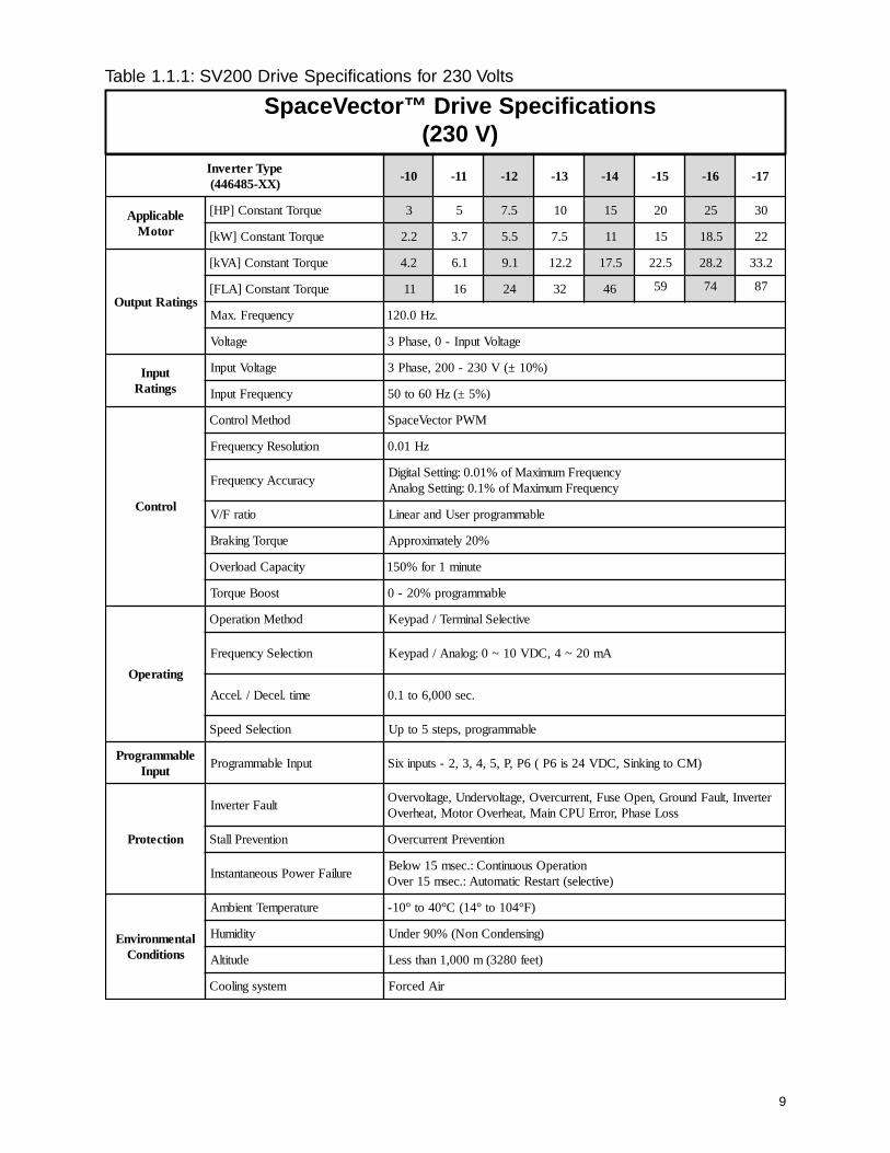
Table 1.1.1: SV200 Drive Specifications for 230 Volts
SpaceVector™ Drive Specifications(230 V)
epyTretrevnI)XX-584644(
01- 11- 21- 31- 41- 51- 61- 71-
elbacilppArotoM
euqroTtnatsnoC]PH[ 3 5 5.7 01 51 02 52 03
euqroTtnatsnoC]Wk[ 2.2 7.3 5.5 5.7 11 51 5.81 22
sgnitaRtuptuO
euqroTtnatsnoC]AVk[ 2.4 1.6 1.9 2.21 5.71 5.22 2.82 2.33
euqroTtnatsnoC]ALF[ 11 61 42 23 64 95 47 78
ycneuqerF.xaM .zH0.021
egatloV egatloVtupnI-0,esahP3
tupnIsgnitaR
egatloVtupnI )%01±(V032-002,esahP3
ycneuqerFtupnI )%5±(zH06ot05
lortnoC
dohteMlortnoC MWProtceVecapS
noituloseRycneuqerF zH10.0
ycaruccAycneuqerFycneuqerFmumixaMfo%10.0:gnitteSlatigiDycneuqerFmumixaMfo%1.0:gnitteSgolanA
oitarF/V elbammargorpresUdnaraeniL
euqroTgnikarB %02yletamixorppA
yticapaCdaolrevO etunim1rof%051
tsooBeuqroT elbammargorp%02-0
gnitarepO
dohteMnoitarepO evitceleSlanimreT/dapyeK
noitceleSycneuqerF Am02~4,CDV01~0:golanA/dapyeK
emit.leceD/.leccA .ces000,6ot1.0
noitceleSdeepS elbammargorp,spets5otpU
elbammargorPtupnI
tupnIelbammargorP )MCotgnikniS,CDV42si6P(6P,P,5,4,3,2-stupnixiS
noitcetorP
tluaFretrevnIretrevnI,tluaFdnuorG,nepOesuF,tnerrucrevO,egatlovrednU,egatlovrevO
ssoLesahP,rorrEUPCniaM,taehrevOrotoM,taehrevO
noitneverPllatS noitneverPtnerrucrevO
eruliaFrewoPsuoenatnatsnInoitarepOsuounitnoC:.cesm51woleB
)evitceles(tratseRcitamotuA:.cesm51revO
latnemnorivnEsnoitidnoC
erutarepmeTtneibmA )F°401ot°41(C°04ot°01-
ytidimuH )gnisnednoCnoN(%09rednU
edutitlA )teef0823(m000,1nahtsseL
metsysgnilooC riAdecroF

10
Table 1.1.2: SV200 Drive Specifications for 460 Volts
SpaceVector™ Drive Specifications(460 V)
epyTretrevnI)XX-584644(
02- 12- 22- 32- 42- 52- 62- 72-
elbacilppArotoM
euqroTtnatsnoC]PH[ 3 5 5.7 01 51 02 52 03
euqroTtnatsnoC]Wk[ 2.2 7.3 5.5 5.7 11 51 5.81 22
sgnitaRtuptuO
euqroTtnatsnoC]AVk[ 2.4 1.6 1.9 2.21 3.81 9.22 7.92 3.43
euqroTtnatsnoC]ALF[ 6 8 21 61 42 03 93 54
ycneuqerF.xaM .zH0.021
egatloVtuptuO egatloVtupnIot0,esahP3
tupnIsgnitaR
egatloVtupnI )%01±(V064-083,esahP3
ycneuqerFtupnI )%5±(.zH06ot05
lortnoC
dohteMlortnoC MWProtceVecapS
noituloseRycneuqerF .zH10.0
ycaruccAycneuqerFycneuqerFmumixaMfo%10.0:gnitteSlatigiDycneuqerFmumixaMfo%1.0:gnitteSgolanA
oitarF/V elbammargorpresUdnaraeniL
euqroTgnikarB %02yletamixorppA
yticapaCdaolrevO etunim1rof%051
tsooBeuqroT elbammargorp%02-0
noitarepO
dohteMnoitarepO evitceleSlanimreT/dapyeK
noitceleSycneuqerF Am02~4,CDV01~0:golanA/dapyeK
emit.leceD/.leccA .ces000,6ot1.0
noitceleSdeepS elbammargorp,spets5otpU
elbammargorPtupnI
tupnIelbammargorP )MCotgnikniS,CDV42si6P(6P,P,5,4,3,2-stupnixiS
noitcetorP
tluaFretrevnIretrevnI,tluaFdnuorG,nepOesuF,tnerrucrevO,egatlovrednU,egatlovrevO
ssoLesahP,rorrEUPCniaM,taehrevOrotoM,taehrevO
noitneverPllatS noitneverPtnerrucrevO
eruliaFrewoPsuoenatnatsnInoitarepOsuounitnoC:.cesm51woleB
)evitceles(tratseRcitamotuA:.cesm51revO
latnemnorivnEsnoitidnoC
erutarepmeTtneibmA )F°401ot°41(C°04ot°01-
ytidimuH )gnisnednoCnoN(%09rednU
edutitlA )teef0823(m000,1nahtsseL
metsysgnilooC riAdecroF
11
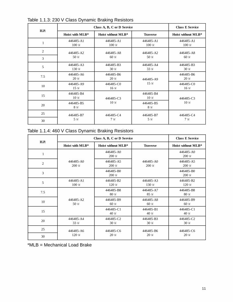
Table 1.1.3: 230 V Class Dynamic Braking Resistors
Table 1.1.4: 460 V Class Dynamic Braking Resistors
.P.HecivreSDroC,B,AssalC ecivreSEssalC
*BLMhtiwtsioH *BLMtuohtiwtsioH esrevarT *BLMtuohtiwtsioH
1
0A-584644002 W
0A-584644002 W
0A-584644002 W
0A-584644002 W
25A-584644
002 W5A-584644
002 W
30B-584644
002 W0B-584644
002 W
51A-584644
001 W2B-584644
021 W3A-584644
031 W2B-584644
021 W
5.7
2A-58464405 W
8B-58464408 W
7A-58464458 W
8B-58464408 W
019B-584644
06 W8A-584644
06 W9B-584644
06 W
511C-584644
04 W1B-584644
04 W1C-584644
04 W
024A-584644
33 W2C-584644
03 W3B-584644
03 W2C-584644
03 W
52 6A-584644021 W
6C-58464402 W
6B-58464402 W
6C-58464402 W03
*MLB = Mechanical Load Brake
.P.HecivreSDroC,B,AssalC ecivreSEssalC
*BLMhtiwtsioH *BLMtuohtiwtsioH esrevarT *BLMtuohtiwtsioH
11A-584644
001 W1A-584644
001 W1A-584644
001 W1A-584644
001 W
2 2A-58464405 W
8A-58464406 W
2A-58464405 W
8A-58464406 W3
53A-584644
031 W3B-584644
03 W4A-584644
33 W3B-584644
03 W
5.76A-584644
02 W6B-584644
02 W 9A-58464451 W
6B-58464402 W
019A-584644
51 W0C-584644
61 W0C-584644
61 W
514B-584644
01 W 3C-58464401 W
4B-58464401 W 3C-584644
01 W02
5B-5846448 W
5B-5846448 W
52 7B-5846445 W
4C-5846447 W
7B-5846445 W
4C-5846447 W03

12
Section 1.2: Mounting the Drive
1.2.1Environmental Conditions
1. Verify the ambient condition of the drive mounting location. The ambient temperaturerange should be 14° to 104°F (-10° to 40°C) for NEMA 1 and or NEMA 4/12 enclosures.
2. The relative humidity should be less than 90% (non-condensing), below the altitude of3280 ft. or 1000m.
3. Do not mount the drive in direct sunlight. The drive should also be isolated from excessivevibration.
4. The drive should be protected from moisture, dust, metallic particles, corrosive gasesand liquids.
5. Consult Factory for severe environments.
1.2.2 Electrical Conditions
1. Verify that Input voltage is within drive nameplate +/- 10%. If input line voltage variesdue to sags and or surges input line reactors are recommended.
2. Analog input requires individually shielded twisted pair cable for installations where thecable leaves the control cabinet.
3. If length of motor leads between drive and motor exceed 100 ft. (30 m) a load reactorbetween drive and motor is recommended.
Mounting
The SV200 must be mounted vertically with sufficient space (horizontally and vertically)between adjacent equipment to permit proper heat dissipation. See Figure 1.2.1. SeeFigures 1.2.2 - 1.2.5 for actual drive dimensions.
13
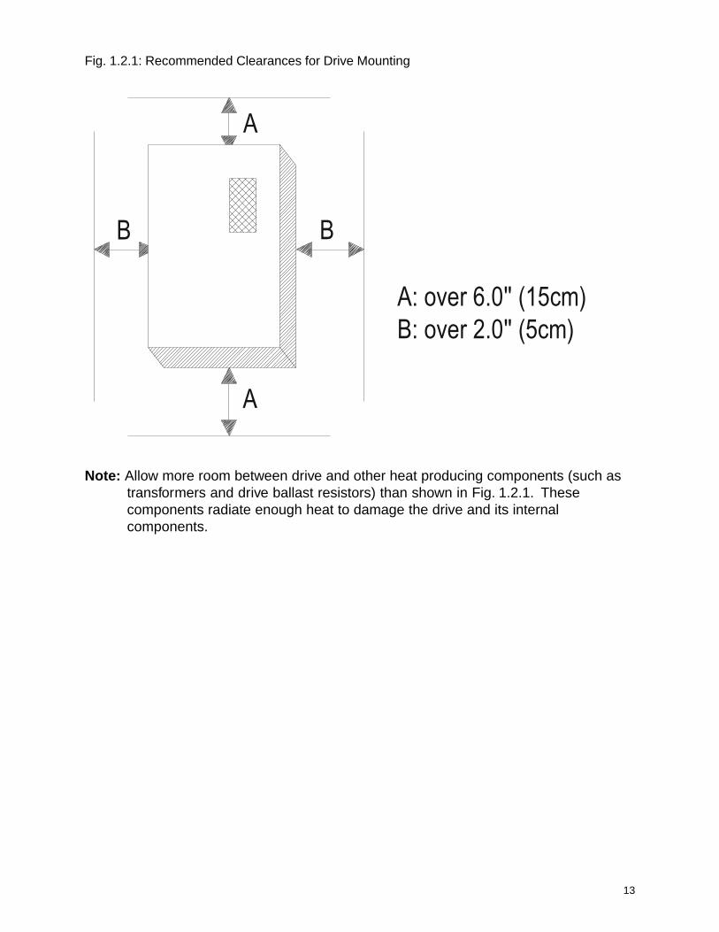
Fig. 1.2.1: Recommended Clearances for Drive Mounting
A: over 6.0'' (15cm)B: over 2.0'' (5cm)
A
A
BB
Note: Allow more room between drive and other heat producing components (such astransformers and drive ballast resistors) than shown in Fig. 1.2.1. Thesecomponents radiate enough heat to damage the drive and its internalcomponents.

14
Drive Dimensions and Weights
Fig. 1.2.2: SV200 Part No. - 446485-10 / 446485-11 418.74lbs (8.5kg)

15
Fig. 1.2.3: SV200 Part Nos. 446485-12 / 446485-13 22.1lbs / 23.2lbs446485-20 / 446485-21 / 446485-22 (10 / 10.5kg)446485-23
7.48’’ (190mm) 8.07’’ (205mm)
.87’’ (22mm)
.87’’ (22mm) 3-dia 1.1’’ (28mm)
.28’’ (7mm)
.28’
’ (7m
m)
13.3
9 (
340m
m)
13.7
8 (
350m
m)
13.9
8 (
355m
m)
8.23
(20
9mm
)
5.20
(13
2mm
)
16
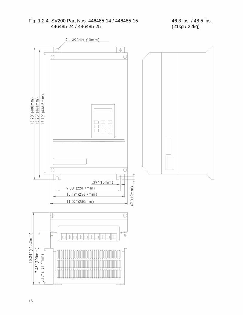
Fig. 1.2.4: SV200 Part Nos. 446485-14 / 446485-15 46.3 lbs. / 48.5 lbs.446485-24 / 446485-25 (21kg / 22kg)
2 - .3 9 ’’ (10 m m )dia.
9 .0 0 ’’ (22 8 .7 m m )
1 0 .19 ’’ (2 5 8 .7m m )
1 1 .02 ’’ (2 8 0m m )
18.9
0’’ (
480m
m)
18.2
3’’ (
463m
m)
17.1
9’’ (
436.
5mm
)
.3 9 ’’ (1 0m m )
.47’
’ (12
mm
)
10.2
4’’ (
260.
2mm
)
7.48
’’ (19
0mm
)
5.17
’’ (13
1.4m
m)

17
Fig. 1.2.5: SV200 Part Nos. 446485-16 / 446485-17 63.9 lbs. / 68.4 lbs.446485-26 / 446485-27 (29kg / 31kg)
1 0 .6 3 ’’ (2 7 0 m m )
4.72
’’ (12
0mm
)8.
17’’ (
210m
m)
11.0
2’’ (
280m
m)
.3 9 ’’ (1 0 m m )
9 .0 6 ’’ (2 3 0 m m )
1 1 .8 1 ’’ (3 0 0 m m )
21.8
9’’ (
556m
m)
21.0
6’’ (
535m
m)
22.8
3’’ (
580m
m)
.47’
’ (12
mm
)
2 - .3 9 ’’ (1 0 m m )d ia.
18
Section 1.3: Wiring the Drive
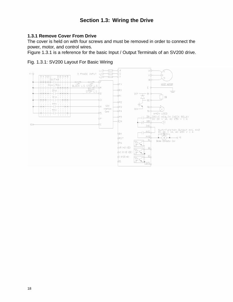
1.3.1 Remove Cover From DriveThe cover is held on with four screws and must be removed in order to connect thepower, motor, and control wires.Figure 1.3.1 is a reference for the basic Input / Output Terminals of an SV200 drive.
Fig. 1.3.1: SV200 Layout For Basic Wiring

19
SV200Drive Class
Drive RatedAmp.
InputAWG
OutputAWG
GroundAWG
DB ResistorAWG
ControlAWG
230VClass
11.012 12
1212
16
16.0
1024.010 10 10
32.0
46.06 6 6 6
59.0
74.04 4 4 4
87.0
460VClass
6.0
12 12 12 128.0
12.0
16.0
24.0
10 10 10 1030.0
39.0
45.0
1.3.2 Check For Correct Wire GaugesInsure the correct wire gauges for the input and output power leads are being used beforewiring the drive. Use Table 1.3.1 for reference.
Table 1.3.1: Wire Gauge Reference Table
1.3.3 Fuse and Circuit Breaker SelectionReference Table 1.3.2 to properly apply fuses and circuit breakers to the drive.
Table 1.3.2: Fuse and Circuit Breaker Selection
SV200Drive Voltage Ref. HP
SV200Part Number
Fuse RatingClass (J)
Molded CaseCircuit Breaker
230V
3 446485-10 20A 25A
5 446485-11 25A 30A
7.5 446485-12 35A 50A
10 446485-13 40A 60A
15 446485-14 50A 75A
20 446485-15 80A 100A
25 446485-16 80A 125A
30 446485-17 100A 150A
460V
3 446485-20 10A15A
5 446485-21 15A
7.5 446485-22 20A30A
10 446485-23 25A
15 446485-24 35A 40A
20 446485-25 40A 50A
25 446485-26 50A 60A
30 446485-27 65A 75A
20
R S T E U V W E B1 B2
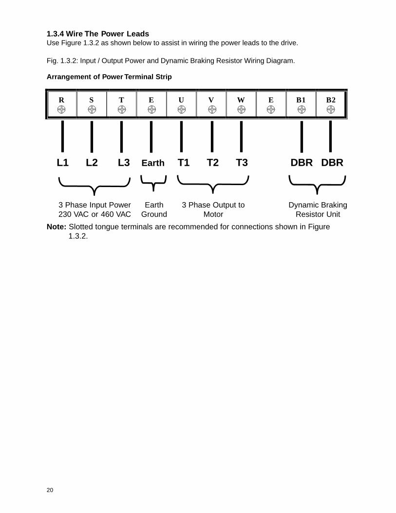
1.3.4 Wire The Power LeadsUse Figure 1.3.2 as shown below to assist in wiring the power leads to the drive.
Fig. 1.3.2: Input / Output Power and Dynamic Braking Resistor Wiring Diagram.
Arrangement of Power Terminal Strip
L1 L2 L3 Earth T1 T2 T3 DBR DBR
3 Phase Input Power230 VAC or 460 VAC
3 Phase Output toMotor
Dynamic BrakingResistor Unit
EarthGround
Note: Slotted tongue terminals are recommended for connections shown in Figure1.3.2.
21
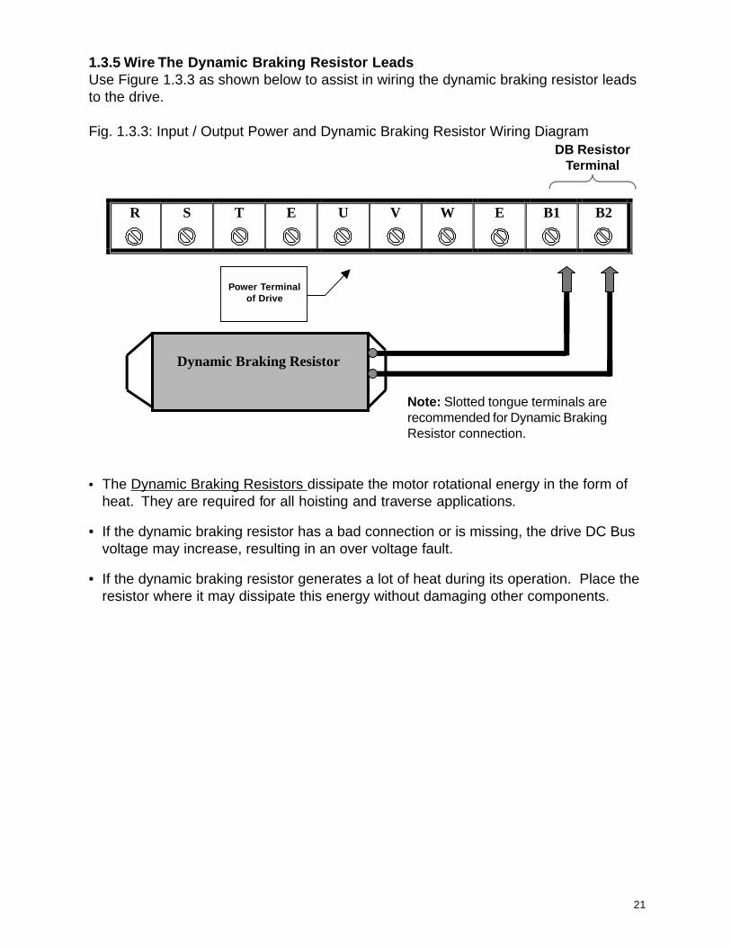
1.3.5 Wire The Dynamic Braking Resistor LeadsUse Figure 1.3.3 as shown below to assist in wiring the dynamic braking resistor leadsto the drive.
Fig. 1.3.3: Input / Output Power and Dynamic Braking Resistor Wiring Diagram
R
S
T
E
U
V
W
E
B1
B2
Dynamic Braking Resistor
DB ResistorTerminal
• The Dynamic Braking Resistors dissipate the motor rotational energy in the form ofheat. They are required for all hoisting and traverse applications.
• If the dynamic braking resistor has a bad connection or is missing, the drive DC Busvoltage may increase, resulting in an over voltage fault.
• If the dynamic braking resistor generates a lot of heat during its operation. Place theresistor where it may dissipate this energy without damaging other components.
Power Terminalof Drive
Note: Slotted tongue terminals arerecommended for Dynamic BrakingResistor connection.
22
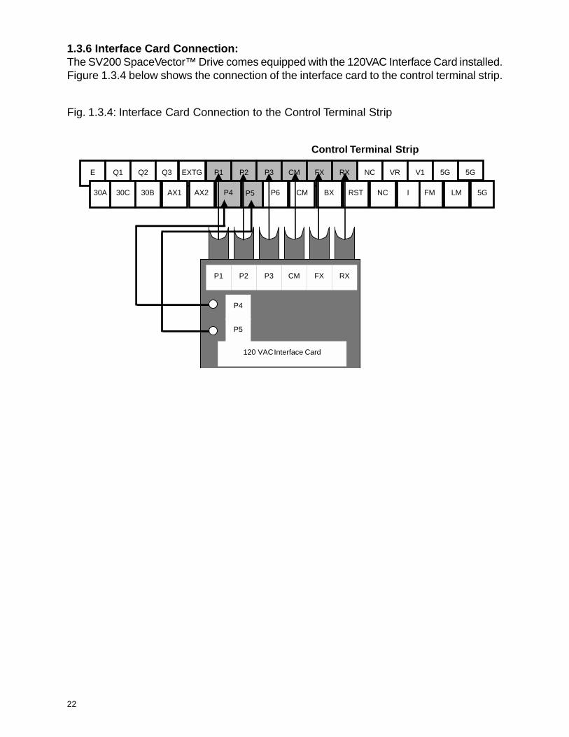
1.3.6 Interface Card Connection:The SV200 SpaceVector™ Drive comes equipped with the 120VAC Interface Card installed.Figure 1.3.4 below shows the connection of the interface card to the control terminal strip.
Fig. 1.3.4: Interface Card Connection to the Control Terminal Strip
Control Terminal Strip
E Q1 Q2 Q3 EXTG P1 P2 P3 CM FX RX NC VR V1 5G 5G
30A 30C 30B AX1 AX2 P4 P6 CM BX RST NC FM LM 5G
P1 P2 P3 CM FX RX
P4
P5
120 VAC Interface Card
I P5

23
1.3.7 Connect the Pushbutton Pendant Control WiresWire the pushbutton pendant control to the pendant input terminals. See Figure 1.3.5below for wiring diagram. Once the pendant is wired, check to determine that the motorturns in the correct direction with respect to the pendant button pressed. Consult Chapter4, Troubleshooting, for help if there is a problem.Note: The Interface card requires 120VAC input signal from your external push button.
Fig. 1.3.5: Push Button Wiring Diagram
Brake Release
120VAC Input from Pushbutton
Raise/forward traverse
Lower/reverse traverse
Speed 2
Speed 3
Speed 4
Speed 5
Programmable Input
120VAC Common
120VAC Interface Card Input Terminal for Pushbutton
SV200 Series Drive
F
R
2
3
30B
30C
AX1
AX2
4
5
P
C
24
Symbol Function
Q1
MULTI-FUNCTION OPEN COLLECTOR OUTPUTQ2
Q3
V1 Analog speed reference input terminal (0~+10 VDC) (Potentiometer connection terminal)
VR Voltage power supply for V1 terminal (+11 VDC)
I Current speed reference input terminal (4~20 mA)
FM Output Frequency Meter [+24 VDC Max. 50mA Max.]
LM Load Meter [+24 VDC Max. 50mA Max.]
5G Common terminal for [V1], [I], [FM]
Symbol Function
FX Forward / Up direction command terminal Speed 1 [120VAC Interface Card Input Terminal]
RX Reverse / Down direction command terminal Speed 1 [120VAC Interface Card Input Terminal]
BX Emergency stop command terminal
RST Fault reset command terminal
P1
MULTI-FUNCTION INPUT
P2
P3
P4
P5
P6
CMCommon terminal for [FX], [RX], [BX], [P1], [P2], [P3], [P4], [P5], [RST] [120VAC Interface Card InputTerminal]
AX1MULTI-FUNCTION RELAY OUTPUT
AX2
30A Relay output terminal (Normal open contact) [DC 30V, AC 250V, 1A]
30B Relay output terminal (normally closed contact) [DC 30V, AC 250V, 1A]
30C Relay output terminal (common terminal) [DC 30V, AC 250V, 1A]
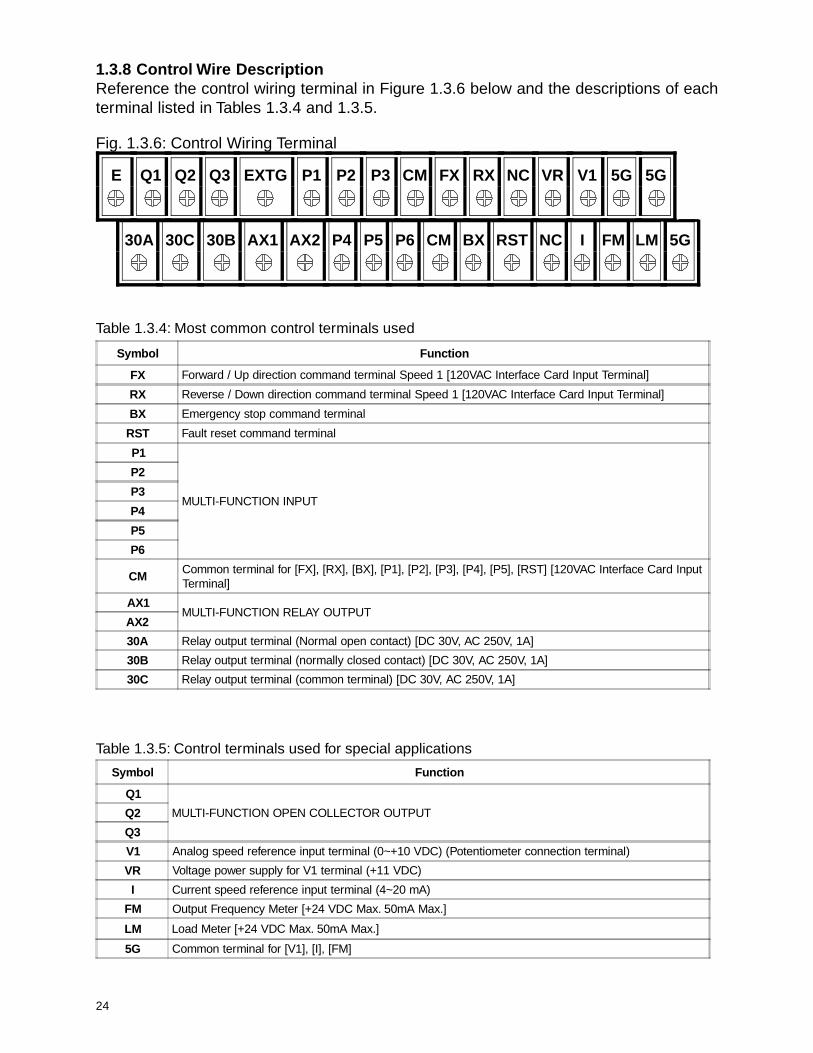
1.3.8 Control Wire DescriptionReference the control wiring terminal in Figure 1.3.6 below and the descriptions of eachterminal listed in Tables 1.3.4 and 1.3.5.
Fig. 1.3.6: Control Wiring Terminal
Table 1.3.4: Most common control terminals used
Table 1.3.5: Control terminals used for special applications
30A 30C 30B AX1 AX2 P4 P5 P6 CM BX RST NC I FM LM 5G
E Q1 Q2 Q3 EXTG P1 P2 P3 CM FX RX NC VR V1 5G 5G

25
1.3.9 Make Precautionary Checks Before Operation
1. Make sure the input voltage level to the drive is correct. Refer to the Drive SpecificationTables 1.1.1 and 1.1.2.
2. Check the power and control connections. All wires should be connected tightly to theterminal.
3. Check the 120VAC source for the control pushbutton.
4. The length of the output wires between the SV200 and the motor must not exceed 100feet.
5. Check the drive and motor ground and make sure there is no ground loop problem.Ensure that all motors and drives connected from a common panel are connected to asingle ground point. See Fig. 1.3.7 for an example.
Fig. 1.3.7: Ground Connection Comparison

26
This page intentionally left blank.

27
Chapter 2: Start Up Programming
Section 2.1: Keypad Layout
Section 2.2: Keypad Operation
2.2.1: Definitions
2.2.2: Moving through the Program
2.2.3: View a Specific Function using Jump Code Location
2.2.4: View all Functions within a Group Level
2.2.5: Change Control from Pendant to Keypad
Section 2.3: Initial Setup Programming
2.3.1: Programming the Drive for a Specific Application
2.3.2: Programming the Speed Selection
2.3.3: Drive Operation Checks
28
Section 2.1: Keypad Layout
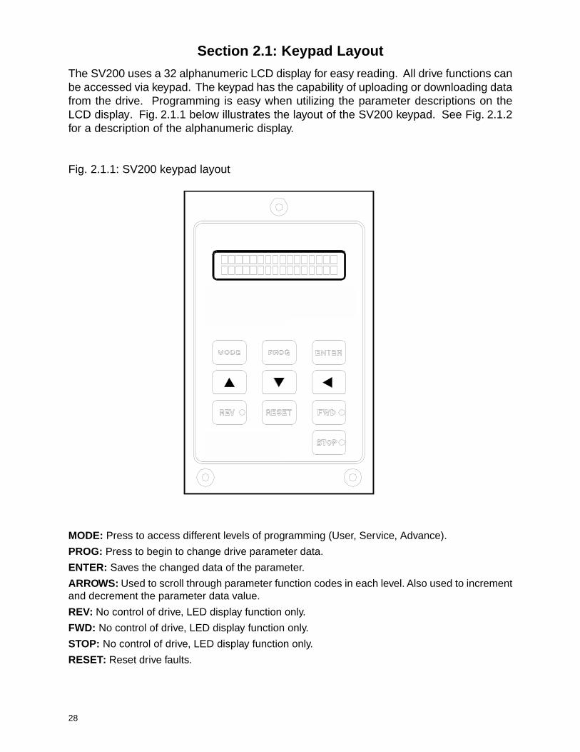
The SV200 uses a 32 alphanumeric LCD display for easy reading. All drive functions canbe accessed via keypad. The keypad has the capability of uploading or downloading datafrom the drive. Programming is easy when utilizing the parameter descriptions on theLCD display. Fig. 2.1.1 below illustrates the layout of the SV200 keypad. See Fig. 2.1.2for a description of the alphanumeric display.
Fig. 2.1.1: SV200 keypad layout
MODE: Press to access different levels of programming (User, Service, Advance).
PROG: Press to begin to change drive parameter data.
ENTER: Saves the changed data of the parameter.
ARROWS: Used to scroll through parameter function codes in each level. Also used to incrementand decrement the parameter data value.
REV: No control of drive, LED display function only.
FWD: No control of drive, LED display function only.
STOP: No control of drive, LED display function only.
RESET: Reset drive faults.

29
Fig. 2.1.2: Alphanumeric Display
USE Manual K/K 00 REV 30.00 Hz
Parameter Display - Manual mode is selected here.
Direction of rotation Drive output frequency during run, otherwise display s command freq.
Parameter level
Parameter code no.
Source control input command [terminal (T) or keypad (K)]
Reference frequency by [ terminal (T) or keypad (K) ]

30
Section 2.2: Keypad Operation
Keypad operation and moving through the parameters of each group access level is astraight forward process. First read the definitions below.
2.2.1 DefinitionsLevels - The SV200 program consists of three group levels. The levels are the User,Service, and Advanced. Each level consists of different function commands which controlhow the drive operates, senses, and performs.
User Level (Use on SV200 Display) - This level allows programming speed, passwords,and the motion application desired. You can also monitor motor current draw and systemfaults in this level. You are automatically in the User level upon power up of yourdrive.
Service Level (Ser on SV200 Display) - The functions within this group primarily set howthe drive will perform, sense problems, and set parameters catered to your motor for peakoperation.
Advanced Level (Adv on SV200 Display) - Functions within this level are reserved forspecial performance characteristics and consists of advanced performance parameters.
2.2.2 Moving Through the Program
When the drive is first powered up, the first Function Code of the User Level is displayed.Please follow the keypad button prompts illustrated in Figures 2.2.1, 2.2.2 and 2.2.3 anduse Table 2.2.1: Function Code List For All Levels to help follow program flow.

31
• To see how to view each Function Code number in a group level, see Figures 2.2.2 and 2.2.3.
Fig. 2.2.1: Programming flowchart showing how to move through each group level.
Mode USE Speed 1 05 60.00 Hz
USE 00 10.00 Hz
SER Jump Code 00 XX
ADV Jump Code 00 XX
USE00 10.00 Hz
Mode
Mode
Mode
The quickest way to move from group level to group level is by following this procedure.In this example, the user is currently in the User Level at Speed 1 [USE: Code No. 05].
• Press the Mode key. This will take you to the firstfunction of whatever level you are currently in.
• Press the Mode key a 2nd time. This will take youto the first function of the next group level.
• Press the Mode key again. This will take you tothe first function of the next group level.
• Press the Mode key again. This will take you backto the first function of the original group level youstarted in.
Note: This jump code location value will be differentdepending on which function code no. the user waspreviously in.
Note: The 1st speedfrequency depends onprogrammed value.
32
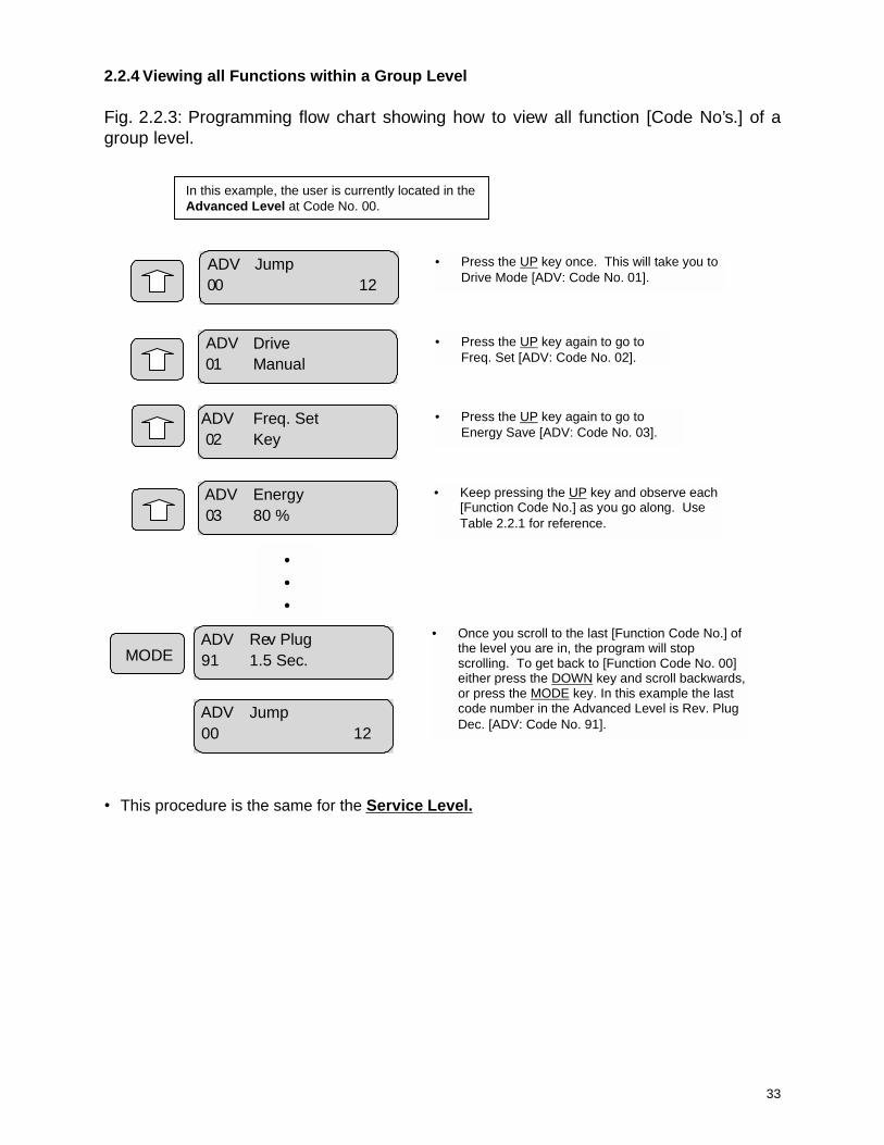
• This procedure is the same for the Advanced Level.
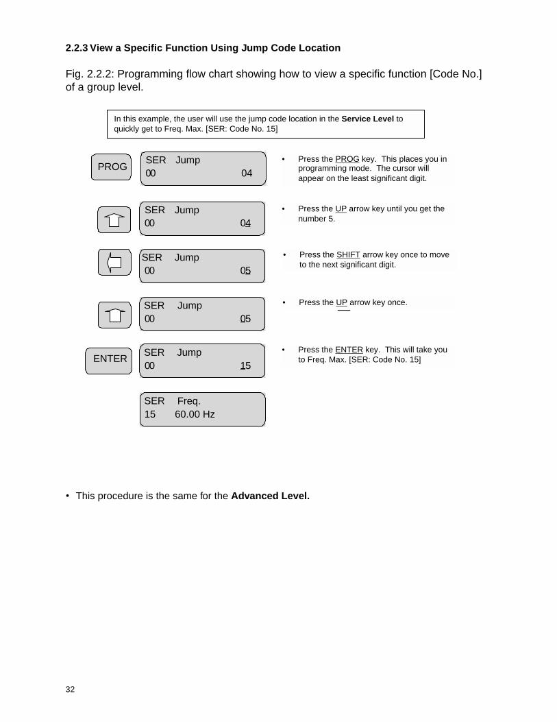
2.2.3 View a Specific Function Using Jump Code Location
Fig. 2.2.2: Programming flow chart showing how to view a specific function [Code No.]of a group level.
PROG
SER Jump 00 04
SER Jump 00 05
SER Jump 00 05
ENTERSER Jump 00 15
SER Jump 00 04
SER Freq.15 60.00 Hz
In this example, the user will use the jump code location in the Service Level toquickly get to Freq. Max. [SER: Code No. 15]
• Press the PROG key. This places you inprogramming mode. The cursor willappear on the least significant digit.
• Press the UP arrow key until you get thenumber 5.
• Press the SHIFT arrow key once to moveto the next significant digit.
• Press the UP arrow key once.
• Press the ENTER key. This will take youto Freq. Max. [SER: Code No. 15]
33
• This procedure is the same for the Service Level.
2.2.4 Viewing all Functions within a Group Level
Fig. 2.2.3: Programming flow chart showing how to view all function [Code No’s.] of agroup level.
ADV Drive 01 Manual
ADV Freq. Set 02 Key
ADV Energy 03 80 %
ADV Rev Plug91 1.5 Sec.
ADV Jump 00 12
ADV Jump00 12
•••
MODE
In this example, the user is currently located in theAdvanced Level at Code No. 00.
• Press the UP key once. This will take you toDrive Mode [ADV: Code No. 01].
• Press the UP key again to go toFreq. Set [ADV: Code No. 02].
• Press the UP key again to go toEnergy Save [ADV: Code No. 03].
• Keep pressing the UP key and observe each[Function Code No.] as you go along. UseTable 2.2.1 for reference.
• Once you scroll to the last [Function Code No.] ofthe level you are in, the program will stopscrolling. To get back to [Function Code No. 00]either press the DOWN key and scroll backwards,or press the MODE key. In this example the lastcode number in the Advanced Level is Rev. PlugDec. [ADV: Code No. 91].
34
JOG JOG MODE
00 STOP
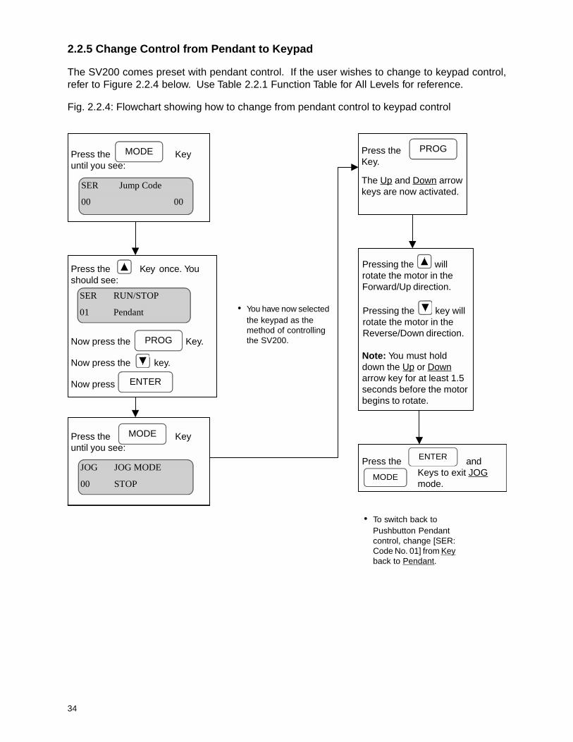
2.2.5 Change Control from Pendant to Keypad
The SV200 comes preset with pendant control. If the user wishes to change to keypad control,refer to Figure 2.2.4 below. Use Table 2.2.1 Function Table for All Levels for reference.
Fig. 2.2.4: Flowchart showing how to change from pendant control to keypad control
• You have now selectedthe keypad as themethod of controllingthe SV200.
Press the Key once. Youshould see:
MODEPress the Keyuntil you see:
Now press the Key.
Now press the key.
Now press
PROG
ENTER
MODEPress the Keyuntil you see:
• To switch back toPushbutton Pendantcontrol, change [SER:Code No. 01] from Keyback to Pendant.
Press the andKeys to exit JOGmode.
ENTER
Pressing the willrotate the motor in theForward/Up direction.
Pressing the key willrotate the motor in theReverse/Down direction.
Note: You must holddown the Up or Downarrow key for at least 1.5seconds before the motorbegins to rotate.
The Up and Down arrowkeys are now activated.
Press theKey.
PROG
MODE
SER RUN/STOP
01 Pendant
JOG JOG MODE
00 STOP
SER Jump Code
00 00

35
Table 2.2.1: Function Code List For All Levels
leveLedoC.oN yalpsiD noitpircseD egnaR tluafeD
resU
00 0.01ycneuqerf1deepssyalpsiD
lautcadnapotSgnirudnuRgnirudtuptuoycneuqerf
zH51RES-0 zH0.01
10 feDnoitoM noitacilppaevirdenifeDesrevarT•
BLwtsioH•BLowtsioH•
BLwtsioH
20 leSdeepSnoitacilppadeepsenifeD
petS2•raVfnIpetS2•
petS3•raVfnIpetS3•
petS5•
petS2
30 tnerruCtnerructuptuO:ylnoyalpsiD
]smr[
40 deepSsuonorhcnyS:ylnoyalpsiD
]mpr[deeps
50 2deepS
.deepSpetS-itluMehtnosdnepedataDlaitinI
20ESUnignimmargorporcaMzH51RES-0
zH00.06
60 3deepS
zH00.070 4deepS
80 5deepS
90 deepSWSL deepshctiwstimildeepSwoL zH51RES-0 zH00.5
01 emit.ccA emiTnoitareleccA .ces0006-0ces0.1
11 emit.ceD emiTnoitareleceD .ces0006-0
21 tupni.reT yalpsidlanimrettupnifosutatS00000000
4.4noitceSeeS
31 tuptuo.reTlanimrettuptuofosutatS
yalpsid1000
4.4noitceSeeS
41 tluaF )tluafrolamron(sutatstnerruC
51 1tluaftsaL ]1-tluaftnerruc[stluafsuoiverP
61 2tluaftsaL ]2-tluaftnerruc[stluafsuoiverP
71 veLsseccA levelsseccadettimreptnerruC decnavdA
81 drowssaP drowssapretnE ****
91 WPveLreSleveLecivreSegnahC
drowssap9999-0
02 WPveLvdAleveLdecnavdAegnahC
drowssap
12 noisrevW/S20enarC/tsioH
ph01-ph3=Mph03-ph51=L
ecivreS
00 edoCpmuJecivreSni.onedocynaotteG
leveL
10 tespotS/nuR ecruosdnammocnuRyeK•
tnadneP•CLP/584SR•
tnadneP
20 nrettap.ccA nrettaPnoitareleccA raeniL•evruC-S•evruC-U•
evruC-S
30 nrettap.ceD nrettaPnoitareleceD raeniL
36
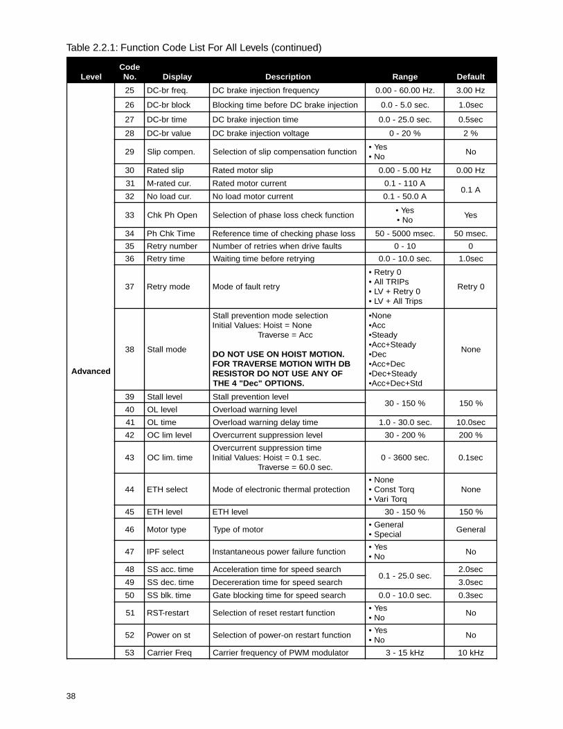
Table 2.2.1: Function Code List For All Levels (continued)
leveLedoC.oN yalpsiD noitpircseD egnaR tluafeD
ecivreS
40 tupnI1P 2tupninoitcnuf-itlumenifeD desUtoN•2leSdpS•3leSdpS•4leSdpS•5leSdpS•
potS.mmIWSL•potS.pmRWSL•
dpSwoLWSL•PIRT_TXE•
2leSdpS
50 tupnI2P 3tupninoitcnuf-itlumenifeD
desUtoN
60 tupnI3P 4tupninoitcnuf-itlumenifeD
70 tupnI4P 5tupninoitcnuf-itlumenifeD
80 tupnI5P Ptupninoitcnuf-itlumenifeD
90 tupnI6P 6Ptupninoitcnuf-itlumenifeD
01 tuptuOXUA tuptuonoitcnuf-itlumenifeDOL_TSF•IH_TSF•IH_TDF•
ESLUP_TDF•DNAB_TDF•
LO•LLATS•
VL•NUR•
IH_TSF
11 tuptuO1Q tuptuonoitcnuf-itlumenifeD OL_TSF
21 tuptuO2Q tuptuonoitcnuf-itlumenifeD IH_TDF
31 tuptuO3Q tuptuonoitcnuf-itlumenifeD LO
41 yticapaCvnI noitceleSledoMevirD
V032@ph3V032@[email protected]@ph01V032@ph51V032@ph02V032@ph52V032@ph03V064@ph3V064@[email protected]@ph01V064@ph51V064@ph02V064@ph52V064@ph03
51 xam.qerF ycneuqerftuptuomumixaM zH021-04zH00.06
61 esab.qerF ycneuqerFesaB zH51RES-04
71 trats.qerF ycneuqerFffotuCevirD zH5-5.0 zH05.0
81 .qerf-llewD
:noituaCycneuqerfllewDtratS3nahtretaergsipilsrotomfI
eesneht,zH esaeleRekarBgnimiT 98egapnonoitces
zH51RES-0 zH00.3
91 emitllewDemiTllewDtratS
.ces5.0=tsioH:seulaVlaitinI.ces1.0=esrevarT
.ces01-0 ces5.0
02 nrettapF/V noitcelesnrettapF/V
raeniL•-0.2• esutonoDresU•
tsooBotuA•
raeniL
12 tsoobdwF tsoobeuqrotnoitceriddrawroF%02-0
%5
22 tsoobveR tsoobeuqrotnoitceridesreveR %2
32 lortnoctloV egatlovtuptuoevirdmumixaM %011-0 %001
42 rebmuneloP seloprotomforebmuN
)mpr0063(2)mpr0081(4)mpr0021(6)mpr009(8)mpr027(01)mpr006(21
4
37
Table 2.2.1: Function Code List For All Levels (continued)
leveLedoC.oN yalpsiD noitpircseD egnaR tluafeD
ecivreS
52 .qerf-TSF ycneuqerFesaeleRekarB zH51RES-05.0 zH10.3
62 daer.araPotevirdmorfsretemaraplladaeR
dapyekseY•
oN•oN
72 etirw.araPotdapyekmorfsretemarapllaetirW
evirdseY•
oN•oN
82 tini.araPyrotcafhtiwsretemarapllaezilaitinI
sgnittestluafedseY•
oN•oN
92 kcol.araP sretemarapllagnimmargorpnokcoL 552-0 0
03 edompotS putesorcamnosdnepedatadlaitinI
leceD•RBCD•
potsetaidemmI•sbAceD/ccA•
etaidemmIpots
decnavdA
00 edoCpmuJ leveLdecnavdAni.onedocynaotteG
10 edomevirDrofelbaliavasiedomlaunamylnO
enarC/tsioH
launaM•-otuA• toNoD
esUlaunaM
20 tes.qerF ecruosycneuqerfdnammoCyeK•
lanimreT•CLP/584SR•
yeK
30 evasygrenE edomgnivasygrenerofeulaV %001-05 %08
40 f1-resU
stniopatadnrettapF/VresU
zH51RES-0 zH00.06
50 v1-resU %001-0 %001
60 f2-resU zH51RES-0 zH00.06
70 v2-resU %001-0 %001
80 f3-resU zH51RES-0 zH00.06
90 v3-resU %001-0 %001
01 f4-resU zH51RES-0 zH00.06
11 v4-resU %001-0 %001
21 edomI-V edomtupnigolanAegatloV•tnerruC•
rruC+tloV•egatloV
31 niagretliF niagretliftupnigolanA %001-0 %05
41 niaggolanA gnilacstupnigolanA %052-05 %001
51 saibgolanA saibtupnigolanA %001-0 %00.0
61 ridgolanA ytiraloptupnigolanAtceriD•trevnI•
tceriD
71 timil.qerF noitcnuftimilycneuqerffognitteSseY•
oN•oN
81 hgihtimil-F ycneuqerfgnitarepomumixaM51RES-91VDA
zHzH00.06
91 woltimil-F ycneuqerfgnitarepomuminiM zH81VDA-0.0 zH00.0
02 pmuj.qerF noitcnufpmujycneuqerffonoitceleSseY•
oN•oN
12 f1pmuj-qerF 1ycneuqerf)ssapyb(pmuJ
zH51RES-0
zH00.01
22 f2pmuj-qerF 2ycneuqerf)ssapyb(pmuJ zH00.02
32 f3pmuj-qerF 3ycneuqerf)ssapyb(pmuJ zH00.03
42 dnab.qerF htdiwdnabycneuqerf)ssapyb(pmuJ zH00.03-00.0 zH00.5
38
Table 2.2.1: Function Code List For All Levels (continued)
leveLedoC.oN yalpsiD noitpircseD egnaR tluafeD
decnavdA
52 .qerfrb-CD ycneuqerfnoitcejniekarbCD .zH00.06-00.0 zH00.3
62 kcolbrb-CD noitcejniekarbCDerofebemitgnikcolB .ces0.5-0.0 ces0.1
72 emitrb-CD emitnoitcejniekarbCD .ces0.52-0.0 ces5.0
82 eulavrb-CD egatlovnoitcejniekarbCD %02-0 %2
92 .nepmocpilS noitcnufnoitasnepmocpilsfonoitceleSseY•
oN•oN
03 pilsdetaR pilsrotomdetaR zH00.5-00.0 zH00.0
13 .rucdetar-M tnerrucrotomdetaR A011-1.0A1.0
23 .rucdaoloN tnerrucrotomdaoloN A0.05-1.0
33 nepOhPkhC noitcnufkcehcssolesahpfonoitceleSseY•oN•
seY
43 emiTkhChP ssolesahpgnikcehcfoemitecnerefeR .cesm0005-05 .cesm05
53 rebmunyrteR stluafevirdnehwseirterforebmuN 01-0 0
63 emityrteR gniyrtererofebemitgnitiaW .ces0.01-0.0 ces0.1
73 edomyrteR yrtertluaffoedoM
0yrteR•sPIRTllA•
0yrteR+VL•spirTllA+VL•
0yrteR
83 edomllatS
noitcelesedomnoitneverpllatSenoN=tsioH:seulaVlaitinIccA=esrevarT
.NOITOMTSIOHNOESUTONODBDHTIWNOITOMESREVARTROF
FOYNAESUTONODROTSISER.SNOITPO"ceD"4EHT
enoN•ccA•
ydaetS•ydaetS+ccA•
ceD•ceD+ccA•
ydaetS+ceD•dtS+ceD+ccA•
enoN
93 levelllatS levelnoitneverpllatS%051-03 %051
04 levelLO levelgninrawdaolrevO
14 emitLO emityaledgninrawdaolrevO .ces0.03-0.1 ces0.01
24 levelmilCO levelnoisserppustnerrucrevO %002-03 %002
34 emit.milCOemitnoisserppustnerrucrevO.ces1.0=tsioH:seulaVlaitinI
.ces0.06=esrevarT.ces0063-0 ces1.0
44 tcelesHTE noitcetorplamrehtcinortcelefoedoMenoN•
qroTtsnoC•qroTiraV•
enoN
54 levelHTE levelHTE %051-03 %051
64 epytrotoM rotomfoepyTlareneG•laicepS•
lareneG
74 tcelesFPI noitcnuferuliafrewopsuoenatnatsnIseY•
oN•oN
84 emit.ccaSS hcraesdeepsrofemitnoitareleccA.ces0.52-1.0
ces0.2
94 emit.cedSS hcraesdeepsrofemitnoitarereceD ces0.3
05 emit.klbSS hcraesdeepsrofemitgnikcolbetaG .ces0.01-0.0 ces3.0
15 tratser-TSR noitcnuftratserteserfonoitceleSseY•
oN•oN
25 tsnorewoP noitcnuftratserno-rewopfonoitceleSseY•
oN•oN
35 qerFreirraC rotaludomMWPfoycneuqerfreirraC zHk51-3 zHk01

39
Table 2.2.1: Function Code List For All Levels (continued)
leveLedoC.oN yalpsiD noitpircseD egnaR tluafeD
decnavdA
45 2qerFevirD
atadnoitacilpparotomowTAtoN( )elbaliav
.zH51RES-0 zH00.0
55 2emit.ccA.ces0.0006-0
ces0.5
65 2emit.ceD ces0.01
75 2esab.qerF .zH51RES-04 zH00.06
85 2nrettapF/V
raeniL•0.2•
resU•tsooBotuA•
raeniL
95 2tsoobdwF%02-0 %2
06 2tsoobveR
16 2levelllatS%051-03 %051
26 2levelHTE
36 lortnocIP noitcnufIPlanretninonoitceleSenoN•
N-ydaetS•R-ydaetS•
enoN
46 niag-P rellortnocIPlanretnifoniagP00003-0
01
56 niag-I rellortnocIPlanretnifoniagI 05
66 tesffOBF-IP langiskcabdeefIPfo)saib(tesffO 05-0 0
76 elacsBF-IP langiskcabdeefIPforotcafgnilacS 052-1 001
86 .verPnuR noitatorfonoitceridenofonoitneverPenoN•
verPesreveR•verPdrawroF•
enoN
96 .qerfgoJ ycneuqerfgniggoJ zH51RES-0 zH00.03
07 retemgolanA retemgolanafoedoMegatloV•tnerruC•
egatloV
17 .jdagolanA retemdaolfotnemtsujdA%021-0 %001
27 .jdaMF retemycneuqerffotnemtsujdA
37 .qerf-TDF levelnoitcetedycneuqerF zH51RES-05.0 zH00.06
47 dnab-TDF dnabnoitcetedycneuqerF zH00.03-00.0 zH00.1
57 rotcafluMyalpsid4-resUrofrotcafgnilacS
999-0001
67 rotcafviD 999-1
77 kcehcDEL dapyektnemges7kcehC A/N A/N
87 noitpO drac)ecafretnI(noitpO
enoN•584SR•
GP•AD/ID•
CLP•NAC•UMP•
enoN
97 rebmun.vnI sserddaretrevnI584SR 23-1 1
08 etar-duaB etarduab584SR
SPB0021•SPB0042•SPB0084•SPB0069•
SPB00291•
SPB0069

40
Table 2.2.1: Function Code List For All Levels (continued)
leveLedoC.oN yalpsiD noitpircseD egnaR tluafeD
decnavdA
18 qerFpilSGP rotomfopilsdetaR zH00.5-00.0 zH00.2
28 niaG-P.GP noitpoGPfoniagP552-1
001
38 niaG-I.GP noitpoGPfoniagI 01
48 langiscnE epytredocnEB+A•ylnoA•
B+A
58 eslupcnE noituloverrepsesluP
esluP063•esluP005•esluP215•
esluP0001•esluP4201•esluP0002•esluP8402•esluP0004•esluP6904•
4201esluP
68 edoMID dracnoitpotupnilatigidfoedoMenoN•.qerF•
.qerF
78 edoMAD dracnoitpotuptuolatigidfoedoM.qerF•
egatloV•tnerruC•
.qerF
88 tuO.TetomeR noitpoNAC/CLP/584SR .ces0.006-0.0 ces0.0
98 gulPveR-elbanegulPesreveR ESUTONOD
NOITOMTSIOHNOseY
oNoN
09 ccAgulPveR gniggulpesreverrofemitnoitareleccA .ces0006-0 ces5.1
19 ceDgulPveR gniggulpesreverrofemitnoitareleceD .ces0006-0 ces5.1
41
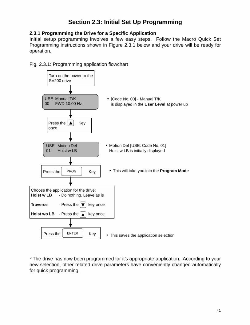
Section 2.3: Initial Set Up Programming
2.3.1 Programming the Drive for a Specific ApplicationInitial setup programming involves a few easy steps. Follow the Macro Quick SetProgramming instructions shown in Figure 2.3.1 below and your drive will be ready foroperation.
Fig. 2.3.1: Programming application flowchart
* The drive has now been programmed for it’s appropriate application. According to yournew selection, other related drive parameters have conveniently changed automaticallyfor quick programming.
• [Code No. 00] - Manual T/Kis displayed in the User Level at power up
• Motion Def [USE: Code No. 01]Hoist w LB is initially displayed
• This will take you into the Program Mode
• This saves the application selection
Press the Key
Turn on the power to theSV200 drive
PROG
USE Manual T/K00 FWD 10.00 Hz
Press the Keyonce
USE Motion Def01 Hoist w LB
Press the KeyENTER
Choose the application for the drive;Hoist w LB - Do nothing. Leave as is
Traverse - Press the key once
Hoist wo LB - Press the key once

42
Reference Table 2.3.1 below for function parameters affected by the Macro Quick SetProgramming procedure in Figure 16. Note: If so desired, these values can be changedindividually by entering the respective access level and changing the function data.
Table 2.3.1: Macro Quick Set Programming values for motion application selection
Macro Set-Up for Traverse
Macro Set-Up for Hoist with Load Brake
Access Level Code No. Description Initial Data
User 0002050607081011
Speed 1Speed Selection
Speed 2Speed 3Speed 4Speed 5
ACC TimeDEC Time
10.00 Hz.2 Step
60.00 Hz.0.00 Hz.0.00 Hz.0.00 Hz.3.0 sec.3.0 sec.
Service 0203040506070830
ACC PatternDEC Pattern
2 Input3 Input4 Input5 InputP Input
Stop Mode
S CurveS Curve
Spd Sel 2Not UsedNot UsedNot UsedNot Used
Decel
Advance 3843899091
Stall PreventionOvercurrent Limit Operation Time
Reverse Plugging EnableReverse Plugging Acceleration TimeReverse Plugging Deceleration Time
Acc60.0 sec
Yes1.5 sec1.5 sec
leveLsseccA .oNedoC noitpircseD ataDlaitinI
resU 0020506070800111
1deepSnoitceleSdeepS
2deepS3deepS4deepS5deepS
emiTnoitareleccAemiTnoitareleceD
.zH00.01petS2
zH00.06zH00.0zH00.0zH00.0ces0.1ces0.1
ecivreS 20304050607080122203
nrettaPnoitareleccAnrettaPnoitareleceD
tupnI1PtupnI2PtupnI3PtupnI4PtupnI5P
tsooBeuqroTdrawroFtsooBeuqroTesreveR
edoMpotS
evruCSraeniL
2leSdpSdesUtoNdesUtoNdesUtoNdesUtoN
%5%2
potSetaidemmI
ecnavdA 833498
noitneverPllatSemiTnoitarepOtnerrucrevO
elbanEgniggulPesreveR
enoNces1.0
oN
43
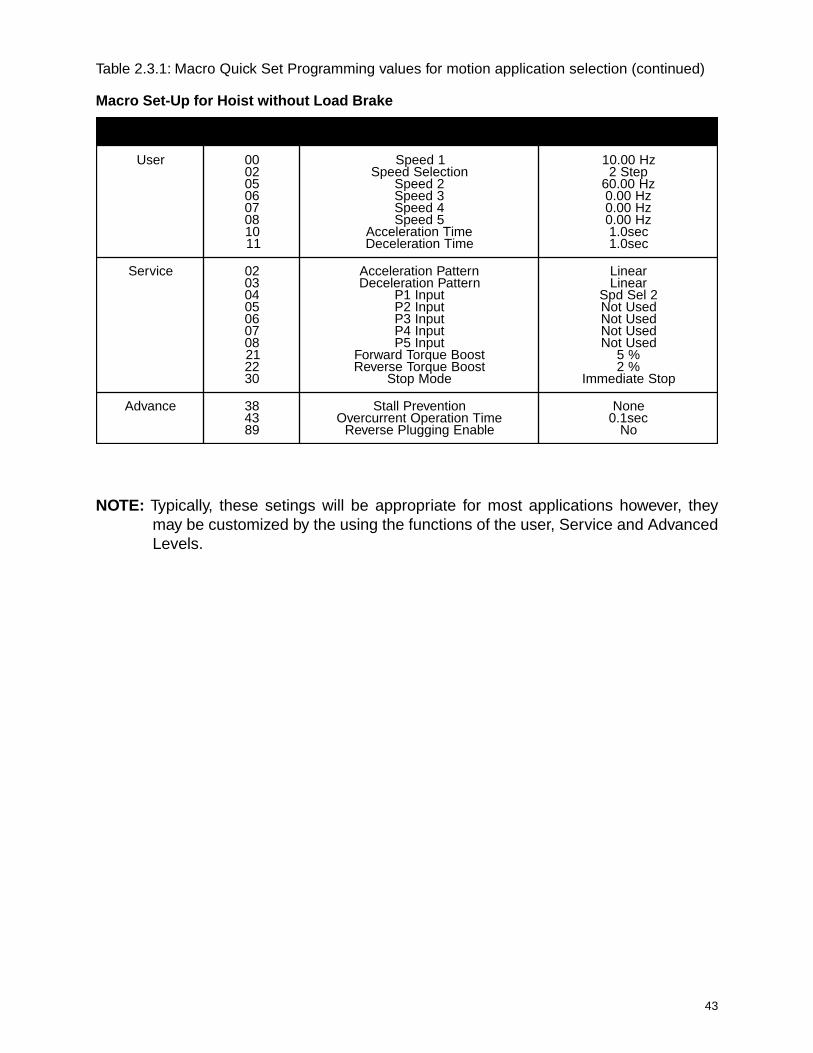
Table 2.3.1: Macro Quick Set Programming values for motion application selection (continued)
Macro Set-Up for Hoist without Load Brake
NOTE: Typically, these setings will be appropriate for most applications however, theymay be customized by the using the functions of the user, Service and AdvancedLevels.
leveLsseccA .oNedoC noitpircseD ataDlaitinI
resU 0020506070800111
1deepSnoitceleSdeepS
2deepS3deepS4deepS5deepS
emiTnoitareleccAemiTnoitareleceD
zH00.01petS2
zH00.06zH00.0zH00.0zH00.0ces0.1ces0.1
ecivreS 20304050607080122203
nrettaPnoitareleccAnrettaPnoitareleceD
tupnI1PtupnI2PtupnI3PtupnI4PtupnI5P
tsooBeuqroTdrawroFtsooBeuqroTesreveR
edoMpotS
raeniLraeniL
2leSdpSdesUtoNdesUtoNdesUtoNdesUtoN
%5%2
potSetaidemmI
ecnavdA 833498
noitneverPllatSemiTnoitarepOtnerrucrevO
elbanEgniggulPesreveR
enoNces1.0
oN

44
2.3.2 Programming the Speed Selection
The last step for initial setup programming is selecting the speed for the respective application.Diagrams showing how the drive operates in the different speed configurations are in theAppendix. Follow the flowchart shown in Figure 2.3.2 below.
Fig. 2.3.2: Speed selection flowchart.
* You have now programmed the drive for its push button speed command. According to your newselection, other related drive parameters have also changed automatically for quick programming.See Table 2.3.2 for changes.
• Speed Sel [USE: Code No. 02]2 Step is initially displayed.
• This will place you intothe Program Mode
• This saves the speed selectionfor your application
Currently you should be in the User Level. Press the
or key until Speed Sel [USE: Code No. 2] is displayed.
USE Speed Sel
02 2 Step
Press the key.PROG
Choose the speed selection for your application:
2 Step -Leave as is. Do nothing.
2 Step Inf Var -Press the key once.
3 Step -Press the key 2 times
3 Step Inf Var -Press the key 3 times
5 Step -Press the key 4 times
Press the key.ENTER

45
Table 2.3.2: Parameters Affected With Speed Selection Programming
• 2 Speed
• 2 Step Infinitely Variable
leveLsseccA .oNedoC noitpircseD ataDlaitinI
resU
05678
1deepS2deepS3deepS4deepS5deepS
zH01zH06
zH0zH0zH0
ecivreS
45678
tupnI1PtupnI2PtupnI3PtupnI4PtupnI5P
2leSdpSdesUtoNdesUtoNdesUtoNdesUtoN
leveLsseccA .oNedoC noitpircseD ataDlaitinI
resU
05678
1deepS2deepS3deepS4deepS5deepS
zH01zH06
zH0zH0zH0
ecivreS
45678
tupnI1PtupnI2PtupnI3PtupnI4PtupnI5P
2leSdpSdesUtoNdesUtoNdesUtoNdesUtoN
• 3 Step
• 3 Step Infinitely Variable
leveLsseccA .oNedoC noitpircseD ataDlaitinI
resU
05678
1deepS2deepS3deepS4deepS5deepS
zH01zH03zH06
zH0zH0
ecivreS
45678
tupnI1PtupnI2PtupnI3PtupnI4PtupnI5P
2leSdpS3leSdpSdesUtoNdesUtoNdesUtoN
leveLsseccA .oNedoC noitpircseD ataDlaitinI
resU
05678
1deepS2deepS3deepS4deepS5deepS
zH01zH03zH06
zH0zH0
ecivreS
45678
tupnI1PtupnI2PtupnI3PtupnI4PtupnI5P
2leSdpS3leSdpSdesUtoNdesUtoNdesUtoN

46
• All speeds can be changed individually in the User Level if so desired.
• In the Appendix are timing graphs representing the different speed control options.
* Your Drive is now ready to run.
Table 2.3.2: Parameters Affected With Speed Selection Programming (continued)
5 Step
leveLsseccA .oNedoC noitpircseD ataDlaitinI
resU
05678
1deepS2deepS3deepS4deepS5deepS
zH01zH02zH03zH54zH06
ecivreS
45678
tupnI1PtupnI2PtupnI3PtupnI4PtupnI5P
2leSdpS3leSdpS4leSdpS5leSdpSdesUtoN
2.3.3 Drive Operation Checks
1. Test with unloaded hoist.
2. Make sure the hoist electric motor brake is operating properly.
3. Run the hoist or traverse, and verify its correct operation in relation to direction ofmovement verses pendant button pressed.
4. Check all limit switches for correct operation.
If the drive operates incorrectly please follow the troubleshooting charts of this manual, orcontact your SpaceVector Dealer for further assistance.TM

47
Chapter 3: Programming
Section 3.1: Passwords and Group Access Levels
3.1.1: Passwords
3.1.2: Entering a Password
3.1.3: Changing Passwords
Section 3.2: Programming Function Data
3.2.1: Customizing the Programming
Section 3.3: Establishing Motor Parameters

48
Section 3.1: Passwords and Group Access Level
Section 3.1.1 Passwords
The SV200 allows you to program up to two passwords. The purpose of a password is toprevent people from inadvertently changing important parameters found in the Serviceand Advanced Levels. In order to change parameters in the Service or AdvancedLevels, you must first enter a password designated to the respective level. The UserLevel does not require a password to change parameters.
When you first receive your drive, the programming permission level is initially setup forthe Advanced Level. This means you can program any parameter in all levels. The initialpassword for all levels is (0). To help explain how passwords affect programming permissionlevels, see Figure 3.1.1.
Section 3.1.2 Entering a Password
When you first receive the SV200 drive, the initial password for all levels is (0). To helpexplain how specific passwords affect each permission level of programming, follow Figure3.1.1. It is assumed that the initial password of (0) has been changed to a (1) for ServiceLevel and a (2) for Advanced Level. If a password change is desired, see Changing aPassword, in Section 3.1.3 of this manual.
Section 3.1.3 Changing a Password
If a password change is desired in either the Service Level or the Advanced Level,reference Figure 3.1.2.
Caution: Once you change your password, make sure it is written down where it can bereferenced at a later time if necessary.

49
Yes
Yes
No
No
Fig. 3.1.1: Flowchart explanation for entering a password and its affect on programmingpermissions.
Get to Password [USE: Code No. 18].
Press thekey.
Press thekey.
Press the , , or key toenter the desired password value.
ENTER
PROG
Does password= (1)
Does password= (2)
Access Lev [USE: Code No. 17]displays the current access levelpermission.
Permission to program in theAdvanced, Service and User Levelis allowed.
Permission to program in the Serviceand User Level is allowed.
An incorrect password entry willautomatically place the user in the UserLevel permission.
Passwords1 = Service Level2 = Advanced Level

50
Fig. 3.1.2: Flowchart showing how to change a password in the Service and AdvancedLevels.
Press the key.ENTER
Press the key.ENTER
Get to Ser Lev PW [USE: Code No. 19]
Press thekey.
PROG
You have now programmeda new password for the
Service Level.
Press the key.ENTER
Press the key.ENTER
Press the , , or key toenter the old password value.
Get to Adv Lev PW [USE: Code No. 20]
Press thekey.
PROG
You have now programmeda new password for the
Advanced Level.
Press the , , or key toenter the new password value.
Press the , , or key toenter the new password value.
Press the , , or key toenter the old password value.
Note: When you firstreceive the SV200, the oldpassword is (0) for bothlevels. Otherwise, use thecurrent respective passwordas the old password.
Changing ServiceLevel Password
Changing AdvancedLevel Password

51
Section 3.2: Programming Function Data
3.2.1 Customizing the Programming
Changing function data requires a few short steps. A password is required for changingany function data in the Service or Advanced Levels. Changing data in the User Leveldoes not require a password. Figure 3.2.1 demonstrates how to change function data inall levels.
Fig. 3.2.1: Programming Speed 1 frequency from 30.00 Hz to 45.50 Hz
Note: In this example, lowering the drive frequency will lower the top speed of the motor.
• Press the PROG key. This places you inthe programming mode. The cursor willappear on the lowest digit.
• Press the SHIFT key once to move to thenext digit.
• Press the UP arrow key 5 times.
• Press the SHIFT key once to shift the cursorto the next digit.
• Press the UP arrow key 5 times.
• Press the SHIFT key once to shift the cursorto the next digit.
• Press the UP arrow key once to change thevalue of 3 to a 4.
• Press the ENTER key to store the newvalue.
USE Speed 2
05 30.00 Hz
USE Speed 2
05 30.00 Hz
USE Speed 2
05 30.50 Hz
USE Speed 2
05 30.50 Hz
PROG
USE Speed 2
05 35.50 Hz
USE Speed 2
05 35.50 Hz
USE Speed 2
05 45.50 Hz
USE Speed 2
05 45.50 HzENTER
Get to the desired parameter you wish to changelisted in the Table 2.1. In this example, Speed 2 [USE:Code No. 5] frequency located in the User Levelwill be changed.
52
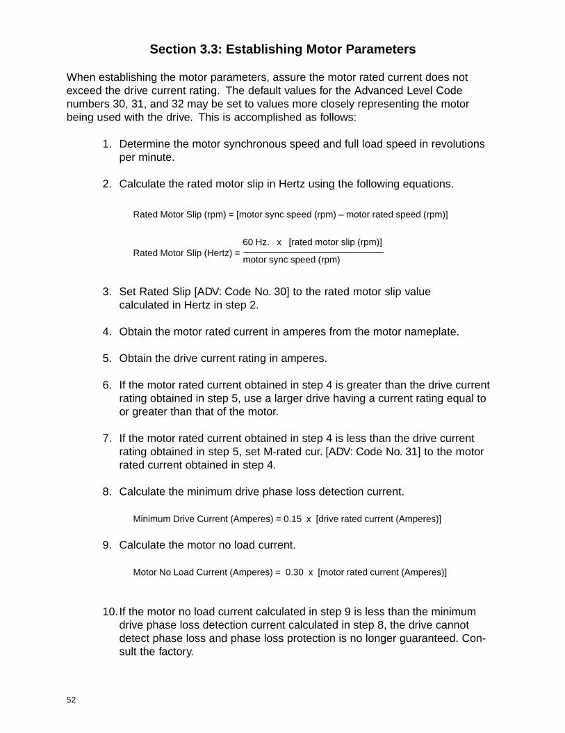
Section 3.3: Establishing Motor Parameters
When establishing the motor parameters, assure the motor rated current does notexceed the drive current rating. The default values for the Advanced Level Codenumbers 30, 31, and 32 may be set to values more closely representing the motorbeing used with the drive. This is accomplished as follows:
1. Determine the motor synchronous speed and full load speed in revolutionsper minute.
2. Calculate the rated motor slip in Hertz using the following equations.
Rated Motor Slip (rpm) = [motor sync speed (rpm) – motor rated speed (rpm)]
Rated Motor Slip (Hertz) =
3. Set Rated Slip [ADV: Code No. 30] to the rated motor slip valuecalculated in Hertz in step 2.
4. Obtain the motor rated current in amperes from the motor nameplate.
5. Obtain the drive current rating in amperes.
6. If the motor rated current obtained in step 4 is greater than the drive currentrating obtained in step 5, use a larger drive having a current rating equal toor greater than that of the motor.
7. If the motor rated current obtained in step 4 is less than the drive currentrating obtained in step 5, set M-rated cur. [ADV: Code No. 31] to the motorrated current obtained in step 4.
8. Calculate the minimum drive phase loss detection current.
Minimum Drive Current (Amperes) = 0.15 x [drive rated current (Amperes)]
9. Calculate the motor no load current.
Motor No Load Current (Amperes) = 0.30 x [motor rated current (Amperes)]
10. If the motor no load current calculated in step 9 is less than the minimumdrive phase loss detection current calculated in step 8, the drive cannotdetect phase loss and phase loss protection is no longer guaranteed. Con-sult the factory.
60 Hz. x [rated motor slip (rpm)]
motor sync speed (rpm)
53
11. If the motor no load current calculated in step 9 is greater than the minimumdrive current calculated in step 8, set No-load cur. [ADV: Code No. 32] to themotor no load current value calculated in step 9.
EXAMPLE:
5 HP drive having rated current of 8 ampere used with 1 HP motor having ratedcurrent of 1.3 amp
Minimum drive current = 0.15 x 8 amp = 1.2 amp
Motor no load current = 0.3 x 1.3 amp = 0.39 amp
The no load motor current is less than the minimum phase loss detection current.If the no load motor current is less than 15% of the drive rated current, the drivemay detect an erroneous phase loss and phase loss protection is no longerguaranteed.

54
This page intentionally left blank.
55
Chapter 4: Troubleshooting
Section 4.1: Monitoring Motor Current and Error Codes
4.1.1: Monitoring Frequency
4.1.2: Monitoring Current
4.1.3: Monitoring Speed
4.1.4: Monitoring Fault Trips
4.1.5: Fault Codes
Section 4.2: Problem Flowcharts
Section 4.3: Testing Power Components
Section 4.4: Pushbutton Pendant Test
Section 4.5: Multi-function Output Test

56
Section 4.1: Monitoring Motor Current and Error Codes
4.1.1 Monitoring Frequency
Actual frequency output is displayed at Speed 1 [USE: Code No. 00]. When the drive isnot in its running mode, the keypad will display Speed Step 1 Frequency as shown inFigure 4.1.1 below. Once the drive starts to run, the keypad will display actual frequencyoutput.
Fig. 4.1.1: Keypad display for drive at rest and in running mode.
4.1.2 Monitoring Current
Actual current output is displayed at Current [USE: Code No. 03]. Figure 4.1.2 belowshows what the current display will look like.
Fig. 4.1.2: SV200 actual current output display
4.1.3 Monitoring Speed
Actual motor speed is displayed at Speed [USE: Code No. 04]. Figure 4.1.3 below showswhat the motor speed display will look like.
Fig. 4.1.3: Motor speed display
• Speed 1 value when drive is at rest.
• Example of actual speed while drive is inrun mode.
• Example of actual speed of the motor.
• Example of actual current output whendrive is in run mode.
USE Manual K/K 00 30.00 Hz
USE Manual K/K 00 52.25 Hz
USE Current 03 6.8 A
USE Speed 04 1250 rpm

57
• Example of an over current fault that justoccurred.
4.1.4 Monitoring Fault TripsIf a fault trip should occur, you can view what the fault is, its frequency and current at timeof fault by going to Fault [USE: Code No. 14]. You can also view the previous faults at Lastfault 1 [USE: Code No. 15] and Last fault 2 [USE: Code No. 16]. See Figure 4.1.4 below forfault displays.
Fig. 4.1.4: Fault trip and fault trip history displays
• Pressing the PROG key will allow you toview the frequency and current at the timeof fault.
• Press the UP key once and the frequencyat time of fault will appear.
• Press the UP key once more and thecurrent at time of fault will appear.
Note: You may also view the frequency and currentat time of Last Fault 1 and Last Fault 2 by followingthe procedure from Fig. 4.1.4 on [Function Nos.15 and 16].
• Example of a previous fault.
• Example of the next previous fault.
Fig. 4.1.5: Last Fault Memory Locations
It is possible to clear the current fault [Function No. 14], by pressing the key orby turning power off and back on.
RESET
PROG
USE Fault 14 OC Trip
USE Fault 14 OC Trip
USE Fault 14 35.60 Hz
USE Fault 14 45.8 A
USE Last Fault 1 15 OV Trip
USE Last Fault 2 16 Over Heat
58
Risk of Electric Shock - More than one disconnect switchmay be required to de-energize the equipment beforeservicing.
CAUTION
4.1.5 Fault Codes
When a Fault Trip occurs, the inverter cuts off its output and displays the fault status inFault [USE: Code No. 14]. The last two faults are saved in Last fault 1 [USE: Code No. 15]and Last fault 2 [USE: Code No. 16].

59
Note: If the problem persists, please contact your local SpaceVector distributor forassistance.
USE Fault14 Over Heat
USE Fault14 ETH
USE Fault14 EXT Trip
USE Fault14 Fuse Open
USE Fault14 LV Trip
USE Fault14 BX
USE Fault14 GF Trip
USE Fault14 OV Trip
USE Fault14 OC Trip
USE Fault14 OC Trip
USE Fault14 Phase Loss
Table 4.1.1: Fault Code Description
TM
Fault Display Description Solutions The output current of the
inverter has reached the overcurrent protection level.
1. Extended Acc. Time [USE: Code No. 10]. 2. Reduce Fwd boost [SER: Code No. 21] or
Rev boost [SER: Code No. 22]. 3. Check wiring to motor for possible short
circuits. 4. If problem persists, the load inertia may be
too great for the size of inverter. A larger inverter may be required.
Inverter output terminals (U, V, W) shorted to ground.
1. Check the wiring from the inverter to the motor for ground faults.
2. Check motor windings for a ground fault.
The DC bus voltage of the inverter is over the voltage protection level.
1. Check whether the input voltage is within 10% of the inverter nameplate value.
2. Extend Dec. time [USE: Code No. 11] to accommodate a high load inertia. Additional Dynamic Braking resistors may be required to dissipate excessive voltage.
3. Eccentric loads and regenerative loads may cause over voltage trips. A larger inverter may be required to accommodate the larger load requirement.
The output current of the inverter has exceeded the value in OL level [ADV: Code No. 40] for longer than OL time [ADV: Code No. 41].
1. Check for mechanical failure which may have caused excessive motor current (bearing failure, jam, brake sticking, etc.)
The current draw from one or more motor outputs (U, V, W) is not high enough for No-load cur. [ADV: Code No. 32]
1. Check output terminals at the drive and motor splice box.
2. Test motor for open windings.
The internal fuse is open. This is cause when an IGBT on the output side of the inverter is damaged. The fuse opens to prevent further damage.
1. Check to see if IGBT s are damaged. See Section 4.3: Testing Power Components.
2. Replace the fuse.
The internal heat sensor sensed the heat sink temperature of the inverter is over 858 C.
1. Verify the Cooling Fan is rotating? 2. Check to see if the air inlet and outlet are
plugged. 3. Check the ambient temperature.
The motor temperature calculated by the ETH has exceeded the value set in ETH level [ADV: Code No. 45].
1. Check whether the ETH level is set correctly.
2. Check whether the inverter has been operating at a low frequency with a heavy load for along time.
The multi-function input terminal configured as EXT_TRIP is open.
1. Check the multi-function input terminal.
The DC bus voltage of the inverter is under the Low Voltage Protection level.
1. Check the input line voltage.
The BX terminal is closed. 1. Check the BX terminal

60
Section 4.2: Problem Flowcharts
Fig. 4.2.1: Motor Does not Run
No Yes
Yes No
No
Yes
Yes
No
No
Yes
No
Yes
No
No
Yes Yes
Yes
No
Is the display on?Inverter trouble. Check keypador power components See Section4.3 for Testing Power Components.Contact factory for assistance.
Is there input power?
• Check input fuses.
• Check circuit breakers.
• Is the mainline contactor energized?
Is RST or BXterminal disabled?
Is Run/stop set [SER: Code No. 01]set to Pendant?
Is Freq. set [ADV: Code No. 02]set to Key?
Is F-limit high [ADV: Code No. 18]greater than 1st speed
Voltage outputfrom U, V, W?
Check outputwiring and
motor.
Call Factory
Adjust max.frequency
Check F and R terminal inputs. See PushbuttonPendant Test in Section 4.4.
Check RST andBX terminal inputs.
Is there analog signal betweenV1-5G or I-5G inputs?
Is F-limit high [ADV: Code No. 18]greater than Freq. start [SER: Code
No. 17]?
Analog signalsource trouble.
Set F-limit highgreater thanFreq. start

61
Fig. 4.2.2: Motor Speed is not equal to the Maximum Operational Frequency
No
Yes
No
Yes
No
Yes
Yes
No
Yes
No
No
Yes
No
Yes
Adjust forcorrectfrequencies.
Change Freq-jump 1f, 2f, 3f [ADV: Code Nos. 21,22, 23] and/or Freq. band [ADV: Code No. 24].
Is Freq. set[ADV: Code No. 02]
set to Key?
Is Acc. time[USE: Code No. 10] or
Dec. time [USE: Code No. 11]extremely long?
Is Stall Modeselected in Stall mode[ADV: Code No. 38]?
Is there an analogsignal betweenV1-5G or I-5G?
Is Stall level[ADV: Code No. 39]
set correctly?
Analog signalsource trouble.
Change Accelerationor Deceleration timeaccording to load.
Change StallPrevention levelaccording to load
Call Factory
Are F-limit high[ADV: Code No. 18] & F-limit low
[ADV: Code No. 19]set correctly?
Is F-limit high[ADV: Code No. 18] within Freq-jump 1f, 2f, 3f
[ADV: Code Nos. 21, 22, 23]or Freq. band [ADV: Code No. 24]?

62
Yes
No
Yes
No
Yes
No
Yes
No
Fig. 4.2.3: Motor does not run smoothly
Increase Acc. time[USE: Code No. 10] orDec. time [USE: Code No. 11].
Is Acc. time[USE: Code No. 10] or
Dec. time [USE: Code No. 11]time short?
Is Freq. start[SER: Code No. 17]high?
Are control signals fluctuating?
Is there balanced outputvoltage at U, V, W, outputs?
Lower Freq. start[SER: Code No. 17].
Check for noisyelectrical supply.
Check the motor.
Call Factory
63
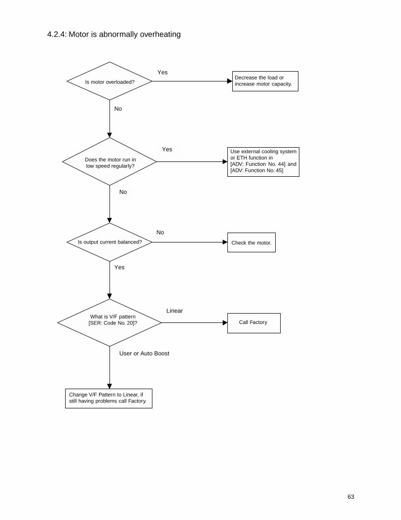
4.2.4: Motor is abnormally overheating
User or Auto Boost
No
Yes
No
Yes
Yes
No
Linear
Change V/F Pattern to Linear, ifstill having problems call Factory.
Use external cooling systemor ETH function in[ADV: Function No. 44] and[ADV: Function No. 45]
Decrease the load orincrease motor capacity.
Check the motor.
Call Factory
Is output current balanced?
Is motor overloaded?
Does the motor run inlow speed regularly?
What is V/F pattern[SER: Code No. 20]?
64
Section 4.3:Testing Power Components
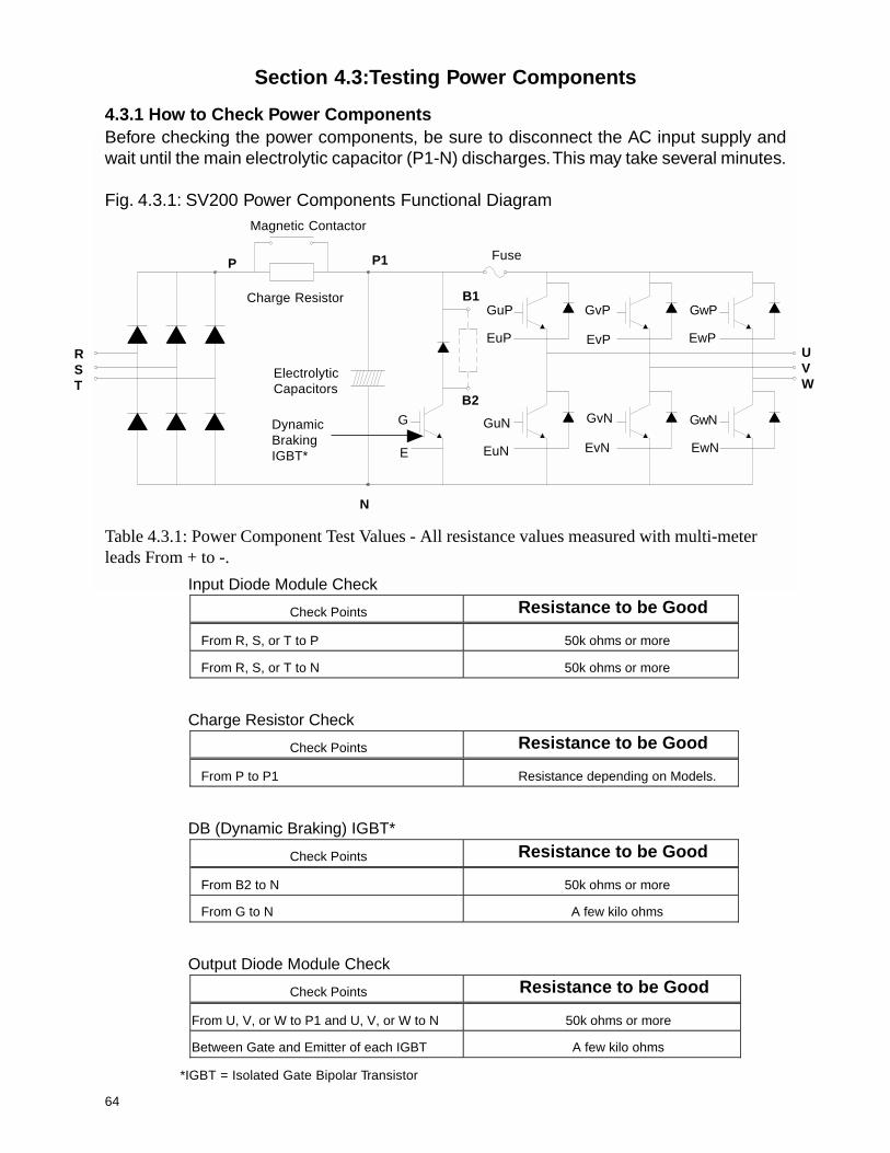
4.3.1 How to Check Power ComponentsBefore checking the power components, be sure to disconnect the AC input supply andwait until the main electrolytic capacitor (P1-N) discharges. This may take several minutes.
Fig. 4.3.1: SV200 Power Components Functional DiagramMagnetic Contactor
RST
UVW
P
N
B1
B2
FuseP1
G
E
GuP
EuP
GuN
EuN
GvP
GvN
GwP
GwN
EvP
EvN
EwP
EwN
ElectrolyticCapacitors
DynamicBrakingIGBT*
Charge Resistor
Input Diode Module Check
Check Points Resistance to be Good
From R, S, or T to P 50k ohms or more
From R, S, or T to N 50k ohms or more
Charge Resistor Check
Check Points Resistance to be Good
From P to P1 Resistance depending on Models.
DB (Dynamic Braking) IGBT*
Check Points Resistance to be Good
From B2 to N 50k ohms or more
From G to N A few kilo ohms
Output Diode Module Check
Check Points Resistance to be Good
From U, V, or W to P1 and U, V, or W to N 50k ohms or more
Between Gate and Emitter of each IGBT A few kilo ohms
Table 4.3.1: Power Component Test Values - All resistance values measured with multi-meterleads From + to -.
*IGBT = Isolated Gate Bipolar Transistor

65
Section 4.4: Pushbutton Pendant Test
The condition of the interface card can be monitored by using the display. This may beviewed at [Function No. 12] in the User Level. Press the PROG key to make the inputdisplay active. See Figure 4.4.1 below for reference.
Fig. 4.4.1: Key for interface card pushbutton pendant test
USE Ter. Input12 0 0 0 0 0 0 0 0
F R 5 4 3 21
st speed
fwd/up
120 VACmulti-function
input
5th speed 4
th speed 3
rd speed 2
nd speed1
st speed
rev/down
P12 VDC
multi-functioninput
P6
Ter. Input [USE: Code No. 12]
USE Ter. Input12 1 0 0 0 0 0 0 0
The status of the input display is dependant upon the status of the corresponding inputto the interface card. If the test of the interface card fails it is recommended that thestatus of the inputs to the control board be tested. The relationship between inputs onthe interface card and inputs on the control are illustrated in Table 4.4.1. Using ajumper wire between an input on the control board and the “CM” terminal will test the 24VDC sinking inputs to the control board.
Table 4.4.1: Interface Card versus Control Board inputs
F XFR XR
6PP 5P5 4P4 3P3 2P2 1P
InterfaceCard
ControlBoard
Example: Figure 4.4.2 shows the drive display if the “F” input on the interface card is on,and likewise the “FX” terminal on the control board.
Fig. 4.4.2: Input Status with “F” and “FX” inputs on
66
Section 4.5: Multifunction Output Test
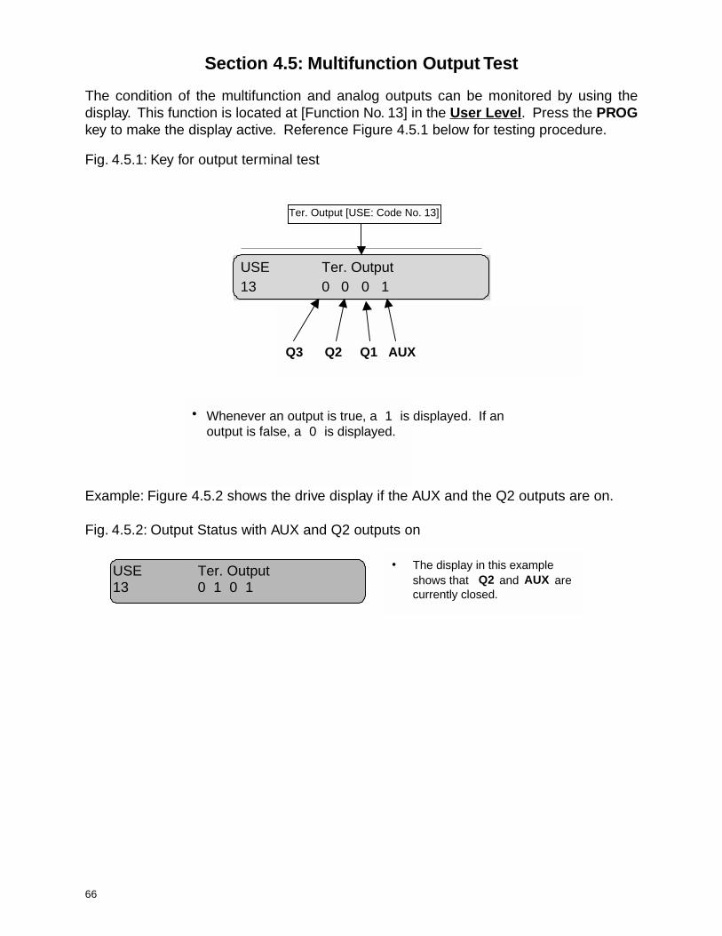
The condition of the multifunction and analog outputs can be monitored by using thedisplay. This function is located at [Function No. 13] in the User Level. Press the PROGkey to make the display active. Reference Figure 4.5.1 below for testing procedure.
Fig. 4.5.1: Key for output terminal test
USE Ter. Output13 0 0 0 1
Q3 Q2 Q1 AUX
• Whenever an output is true, a 1 is displayed. If anoutput is false, a 0 is displayed.
Ter. Output [USE: Code No. 13]
Example: Figure 4.5.2 shows the drive display if the AUX and the Q2 outputs are on.
Fig. 4.5.2: Output Status with AUX and Q2 outputs on
• The display in this example shows that Q2 and AUX are currently closed.
USE Ter. Output 13 0 1 0 1

67
This page intentionally left blank.

68
Chapter 5: Function Code Information
Section 5.1: User Level Functions
5.1.1: Frequency Output Monitor
5.1.2: Frequency Reference
5.1.3: Accel / Decel
5.1.4: Drive Status Monitoring
Section 5.2: Service Level Functions
5.2.1: Command Reference (Run / Stop Selection)
5.2.2: Accel / Decel Patterns
5.2.3: Multi-Function Inputs
5.2.4: Multi-Function Outputs
5.2.5: Drive Model Selection
5.2.6: Frequency Settings
5.2.7: Dwell Function
5.2.8: V / F Pattern
5.2.9: Torque Boost
5.2.10: Voltage Control
5.2.11: Motor Poles
5.2.12: Brake Release
5.2.13: Upload / Download from Keypad and Set Factory Defaults
5.2.14: Braking
Section 5.3: Advanced Level Functions
5.3.1: Drive Mode
5.3.2: Frequency Reference Source
5.3.3: Energy Save
5.3.4: User V / F Pattern
5.3.5: Analog Frequency Control
5.3.6: Maximum / Minimum Operating Frequency
5.3.7: Frequency to Bypass
5.3.8: DC Injection Braking
5.3.9: Motor Data
5.3.10: Drive and Motor Protections
69
5.3.11: Stall Prevention
5.3.12: Instantaneous Power Failure and Speed Search
5.3.13: Restart After Reset
5.3.14: Carrier Frequency
5.3.15: Two Motor Applications
5.3.16: Closed Loop Speed Control
5.3.17: Rotation Direction Prevention
5.3.18: Jog Frequency
5.3.19: Output Current, Voltage and Frequency
5.3.20: Frequency Detection
5.3.21: Speed Display Scaling Factor
5.3.22: LED Check
5.3.23: Option Card
5.3.24: Reverse Plugging
70
Section 5.1: User Level Functions
5.1.1 Frequency Output Monitor
The drive frequency can be monitored via Keypad and Multifunction outputterminals.
VIA KEYPADSpeed 1 [USE: Code No. 00]: 1st Speed (Factory Default: 10.00 Hz)Range: 0.00 - SER 15 Hz
The Keypad displays the drive frequency output to the motor once the RUNcommand is initiated. When the drive is not in RUN mode, the frequency displayindicates the programmed speed 1 frequency.
VIA FREQUENCY METER TERMINAL (See Section 5.3.14)
5.1.2 Frequency Reference
Speed Sel [USE: Code No. 02]: Speed Sel (Factory Default: 2 Step)Range: 2 Step
2Step Inf Var3 Step3Step Inf Var5 Step
Speed 2 [USE: Function No. 05]: 2nd Speed (Factory Default: 60.00 Hz)Range: 0.00 - SER 15 HzSpeed 3 [USE: Function No. 06]: 3rd Speed (Factory Default: 0.00 Hz)Range: 0.00 - SER 15 HzSpeed 4 [USE: Function No. 07]: 4th Speed (Factory Default: 0.00 Hz)Range: 0.00 - SER 15 HzSpeed 5 [USE: Function No. 08]: 5th Speed (Factory Default: 0.00 Hz)Range: 0.00 - SER 15 Hz
The hoist speed references are set in the User Level. Speed 1 and 2 will be appliedwhen Speed Sel is set to 2 Step or 2 Step Infinitely Variable. Speed 1, 2, and 3 willbe applied when Speed Sel is set to 3 Step or 3 Step Infinitely Variable and Speed1, 2, 3, 4 and 5 will be applied when Speed Sel is set to 5 Step. The value of thesespeed points will be limited to the value of Maximum Frequency set in Freq. max[SER: Code No. 15]. Generally, the maximum frequency is set to the maximummotor allowed output speed.
71
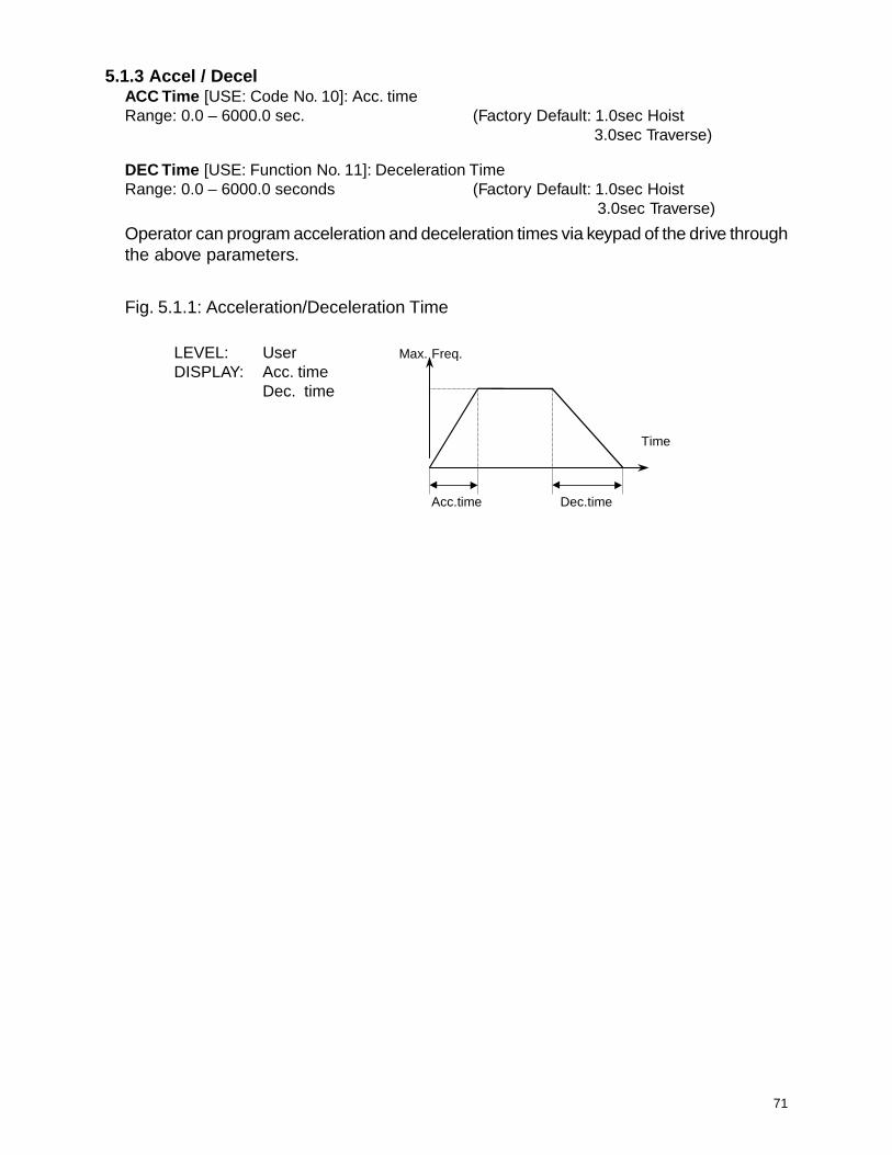
5.1.3 Accel / DecelACC Time [USE: Code No. 10]: Acc. timeRange: 0.0 – 6000.0 sec. (Factory Default: 1.0sec Hoist
3.0sec Traverse)
DEC Time [USE: Function No. 11]: Deceleration TimeRange: 0.0 – 6000.0 seconds (Factory Default: 1.0sec Hoist
3.0sec Traverse)
Operator can program acceleration and deceleration times via keypad of the drive throughthe above parameters.
Fig. 5.1.1: Acceleration/Deceleration Time
Time
Acc.time Dec.time
Max. Freq.LEVEL: UserDISPLAY: Acc. time
Dec. time

72
5.1.4 Drive Status MonitoringThe drive operational status can be monitored via the drive keypad and Multi-Meteroutput terminal.
FAULT HISTORYFaults [USE: Code No. 14] (Display only)Last Fault 1 [USE: Code No. 15] (Display only)Last Fault 2 [USE: Code No. 16] (Display only)
The drive keeps detailed fault information in three fault history parameters. Each faulthistory parameter contains the previous fault status such as fault type, drive outputcurrent and the frequency output at the time of the fault. These conditions can beviewed by the using up and down arrow keys of the keypad. See Section 4.1.2 fordetailed instructions on all fault code locations.
RESETTING A FAULT
The SV200 drive fault can be reset either from the keypad by pressing RESET orfrom the external fault reset terminal RST, or by turning power off and back on afterapproximately 3 min.For the keypad reset, please refer to Section 4.1.2.
STATUS OF INPUT TERMINAL
Drive input terminal status can be monitored in Ter. Input [USE: Code No. 12]. Thisfeature is a useful tool for drive troubleshooting. The status of each terminal is displayedin binary form. When an input terminal is activated, the display will show High (1),otherwise it will show Low (0). See Section 4.4 for a description of this feature.
SOFTWARE VERSION
S/W Ver. [USE: Code No. 21]: S/W Version (Display only)Hoist/Crane 02M = 3 hp - 10 hpL = 15 hp - 30 hp
This is the software version of the SV200 drive.
PASSWORDS
See Section 3.1 for an explanation of this feature.

73
Section 5.2: Service Level Functions
5.2.1 Command Reference (Run/Stop Selection)The drive can receive its command sequence (RUN, STOP, FWD, REV), via externalterminals.
Run/stop set [SER: Code No. 01]: Run command source (Factory Default: Pendant)Range: Key
PendantRS485/PLC
KEYPADThe JOG function works via the keypad only. See Section 2.2.3 for instructions on use.
EXTERNAL CONTROLEach of the sequence command can be initiated via external controls connected throughthe interface card, or direct to the control board. See Table 5.2.1.
Tabel 5.2.1: Drive Input terminals
5.2.2 Accel / Decel PatternsAcc. pattern [SER: Code No. 02]: Acceleration Pattern (Factory Default: S-Curve)Range: Linear
S-CurveU-Curve
Dec. pattern [SER: Code No. 03]: Deceleration Pattern (Factory Default: Linear)Range: Linear
S-CurveU-Curve
These values are set with Motion Def [ USE: Function No. 01], see Table 2.3.1. The usercan select different acceleration and deceleration patterns for smoother hoist or traverseramping.
slanimreTtupnIdraoBlortnoCevirD draCecafretnI
xF CDV42.lanimreTdnammoCnoitceriDdrawroF/pU.gnikniS F CAV021.lanimreTdnammoCnoitceriDdrawroF/pU
.gnicruoS
xR 42.lanimreTdnammoCnoitceriDesreveR/nwoD.gnikniSCDV R 021.lanimreTdnammoCnoitceriDesreveR/nwoD
.gnicruoSCAV
TSR .gnikniSCDV42.teseRteseRtluaF
1P .gnikniSCDV42tupnInoitcnuF-itluM 2 .gnicruoSCAV021tupnInoitcnuF-itluM
2P .gnikniSCDV42tupnInoitcnuF-itluM 3 .gnicruoSCAV021tupnInoitcnuF-itluM
3P .gnikniSCDV42tupnInoitcnuF-itluM 4 .gnicruoSCAV021tupnInoitcnuF-itluM
4P .gnikniSCDV42tupnInoitcnuF-itluM 5 .gnicruoSCAV021tupnInoitcnuF-itluM
5P .gnikniSCDV42tupnInoitcnuF-itluM P .gnicruoSCAV021tupnInoitcnuF-itluM
6P .gnikniSCDV42tupnInoitcnuF-itluM
MC .stupnIgnikniSCDV42roflanimreTnommoC C stupnIgnicruoSCAV021roflanimreTnommoC
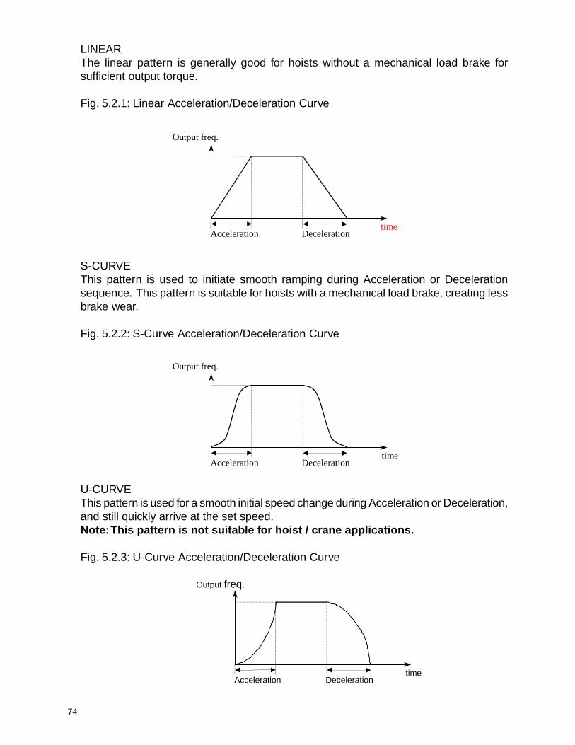
74
Output freq.
timeAcceleration Deceleration
LINEARThe linear pattern is generally good for hoists without a mechanical load brake forsufficient output torque.
Fig. 5.2.1: Linear Acceleration/Deceleration Curve
S-CURVEThis pattern is used to initiate smooth ramping during Acceleration or Decelerationsequence. This pattern is suitable for hoists with a mechanical load brake, creating lessbrake wear.
Fig. 5.2.2: S-Curve Acceleration/Deceleration Curve
Output freq.
timeAcceleration Deceleration
U-CURVEThis pattern is used for a smooth initial speed change during Acceleration or Deceleration,and still quickly arrive at the set speed.Note: This pattern is not suitable for hoist / crane applications.
Fig. 5.2.3: U-Curve Acceleration/Deceleration Curve
Output freq.
timeAcceleration Deceleration
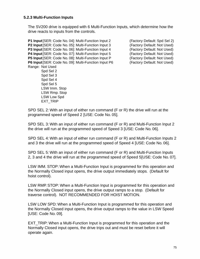
75
5.2.3 Multi-Function Inputs
The SV200 drive is equipped with 6 Multi-Function Inputs, which determine how thedrive reacts to inputs from the controls.
P1 Input [SER: Code No. 04]: Multi-Function Input 2 (Factory Default: Spd Sel 2)P2 Input [SER: Code No. 05]: Multi-Function Input 3 (Factory Default: Not Used)P3 Input [SER: Code No. 06]: Multi-Function Input 4 (Factory Default: Not Used)P4 Input [SER: Code No. 07]: Multi-Function Input 5 (Factory Default: Not Used)P5 Input [SER: Code No. 08]: Multi-Function Input P (Factory Default: Not Used)P6 Input [SER: Code No. 09]: Multi-Function Input P6 (Factory Default: Not Used)Range: Not Used
Spd Sel 2Spd Sel 3Spd Sel 4Spd Sel 5LSW Imm. StopLSW Rmp. StopLSW Low SpdEXT_TRIP
SPD SEL 2: With an input of either run command (F or R) the drive will run at theprogrammed speed of Speed 2 [USE: Code No. 05].
SPD SEL 3: With an input of either run command (F or R) and Multi-Function Input 2the drive will run at the programmed speed of Speed 3 [USE: Code No. 06].
SPD SEL 4: With an input of either run command (F or R) and Multi-Function Inputs 2and 3 the drive will run at the programmed speed of Speed 4 [USE: Code No. 06].
SPD SEL 5: With an input of either run command (F or R) and Multi-Function Inputs2, 3 and 4 the drive will run at the programmed speed of Speed 5[USE: Code No. 07].
LSW IMM. STOP: When a Multi-Function Input is programmed for this operation andthe Normally Closed input opens, the drive output immediately stops. (Default forhoist control).
LSW RMP. STOP: When a Multi-Function Input is programmed for this operation andthe Normally Closed input opens, the drive output ramps to a stop. (Default fortraverse control). NOT RECOMMENDED FOR HOIST MOTION.
LSW LOW SPD: When a Multi-Function Input is programmed for this operation andthe Normally Closed input opens, the drive output ramps to the value in LSW Speed[USE: Code No. 09].
EXT_TRIP: When a Multi-Function Input is programmed for this operation and theNormally Closed input opens, the drive trips out and must be reset before it willoperate again.

76
5.2.4 Multi-Function Outputs
The SV200 drive is equipped 4 Multi-Function Outputs. One is a Normally Opencontact between AX1 and AX2 on the control board. The other three are OpenCollector 24 VDC outputs at Q1, Q2, and Q3, see Fig. 5.2.4.
AUX Output [SER: Code No.10]: AUX Output (Factory Default: FST_HI)Q1 Output [SER: Code No. 11]: Q1 Output (Factory Default: FST_LO)Q2 Output [SER: Code No. 12]: Q2 Output (Factory Default: FDT_HI)Q3 Output [SER: Code No. 13]: Q3 Output (Factory Default: OL)Range: FST_LO (See Section 5.2.12)
FST_HI (See Section 5.2.12)FDT_HI (See Section 5.3.20)FDT_PULSE (See Section 5.3.20)FDT_BAND (See Section 5.3.20)OL (See Section 5.3.10)LVRUN
LOW VOLTAGE SIGNALMulti-Function Output terminals AX1 and AX2 programmed to LV will close when theDC Link voltage falls below the low voltage level of the drive (200VDC for 230 VAC,and 400VDC for 460 VAC drives).
Fig. 5.2.3: Under-voltage Fault Signal
RUN / STOP SIGNALThe Multi-Function Output terminals AX1 and AX2 programmed to RUN will closewhen the drive changes from a stop condition to a run condition.
B3, B4
DC link voltage
time
ON
230V200V
AX1, AX2
QI EXTG
Open Collector Output(24VDC, 50mA)
OL
24V DCSupply
Relay
+
Fig. 5.2.4: Open Collector Multi-function Output
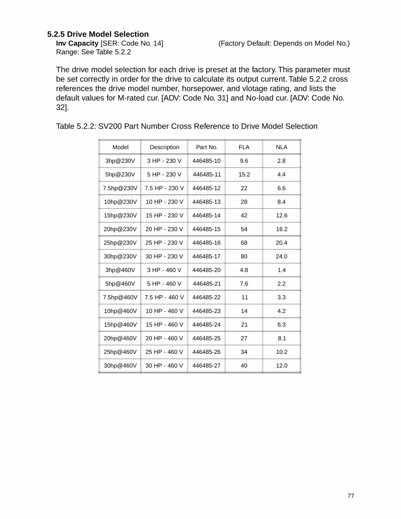
77
5.2.5 Drive Model SelectionInv Capacity [SER: Code No. 14] (Factory Default: Depends on Model No.)Range: See Table 5.2.2
The drive model selection for each drive is preset at the factory. This parameter mustbe set correctly in order for the drive to calculate its output current. Table 5.2.2 crossreferences the drive model number, horsepower, and vlotage rating, and lists thedefault values for M-rated cur. [ADV: Code No. 31] and No-load cur. [ADV: Code No.32].
Table 5.2.2: SV200 Part Number Cross Reference to Drive Model Selection
Model Description Part No. FLA NLA
3hp@230V 3 HP - 230 V 446485-10 9.6 2.8
5hp@230V 5 HP - 230 V 446485-11 15.2 4.4
7.5hp@230V 7.5 HP - 230 V 446485-12 22 6.6
10hp@230V 10 HP - 230 V 446485-13 28 8.4
15hp@230V 15 HP - 230 V 446485-14 42 12.6
20hp@230V 20 HP - 230 V 446485-15 54 16.2
25hp@230V 25 HP - 230 V 446485-16 68 20.4
30hp@230V 30 HP - 230 V 446485-17 80 24.0
3hp@460V 3 HP - 460 V 446485-20 4.8 1.4
5hp@460V 5 HP - 460 V 446485-21 7.6 2.2
7.5hp@460V 7.5 HP - 460 V 446485-22 11 3.3
10hp@460V 10 HP - 460 V 446485-23 14 4.2
15hp@460V 15 HP - 460 V 446485-24 21 6.3
20hp@460V 20 HP - 460 V 446485-25 27 8.1
25hp@460V 25 HP - 460 V 446485-26 34 10.2
30hp@460V 30 HP - 460 V 446485-27 40 12.0

78
5.2.6 Frequency Settings
Freq. max [SER: Code No. 15]: Maximum output frequency (Factory Default: 60.00 Hz)Range: 40.00 - 120.00 Hz
Freq. base [SER: Code No. 16]: Base frequency (Factory Default: 60.00 Hz)Range: 40.00 - Ser 15 Hz
Freq. start [SER: Code No. 17]: Drive Cutoff Frequency (Factory Default: 0.50 Hz)Range: 0.50 - 5.00 Hz
The Freq. base [SER: Code No. 16] is the motor rated speed in the constant torquerange. This base frequency value should not be set higher than that of Freq. max [SER:Code No. 15]. If the base frequency is set at 40 Hz and the maximum frequency is setat 60 Hz, the motor will accelerate up to 40Hz. in Constant Torque mode and up to 60Hz in Constant Horsepower mode. The Drive Cutoff Frequency set in Freq. start [SER:Code No. 17] is the frequency at which the drive shuts off when ramping to a stop.
Fig. 5.2.5: Motor Frequency Relationship Diagram
Output volt.
Constant Torque range Constant Horsepower range
Output freq.Freq. Base
[SER: Code No. 16]Freq. Max.
[SER: Code No. 15]
100%
Dwell time[SER: Code No. 19]
Dwell Freq.[SER: Code No.18]

79
5.2.7 Dwell FunctionDwell-freq. [SER: Code No. 18]: Start Dwell Frequency (Factory Default: 3.00 Hz)Range: 0 - SER 15 HzDwell-time [Ser: Code No. 19]: Start Dwell Time (Factory Default: 0.5 sec)Range: 0 - 10 sec.
The dwell function is used for torque proving before the brake is released. Thecurrent is applied to the motor during the Dwell-time [SER: Code No. 19] beforereleasing the brake.Caution: Dwell frequency should be set to the slip frequency of the motor if the slip isgreater than 3 Hz. To calculate slip frequency, see Section 3.3.
Fig. 5.2.6: Brake Release Timing (Hoist)
Fout
F o r R inpu t
B rake R e lease (A X 1 A X 2)
D w ell-F req . [S E R : C ode N o. 18 ]
D w ell T im e [S E R : C ode N o. 19 ]
FS T -frequency [ S E R : C ode N o.25 ]
time
F or R input
Brake Release (AX1 AX2)
Dwell-Freq. [SER: Code No. 18]
Dwell-T ime [SER: Code No. 19]
FST-frequency [SER: Code No. 25]
Cutoff Freq. [SER: Code No. 17]
time
time
Fout
Fig. 5.2.7: Brake release Timing (Traverse)
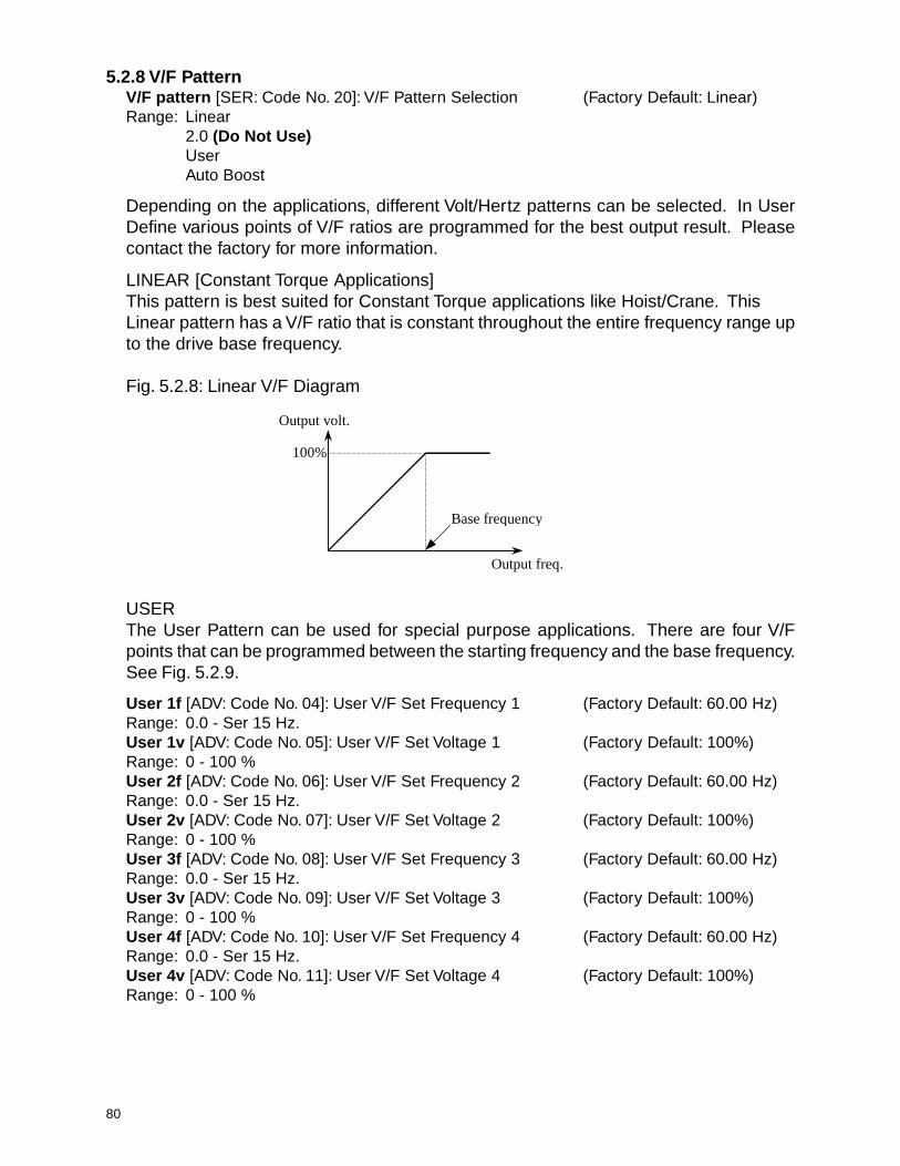
80
5.2.8 V/F PatternV/F pattern [SER: Code No. 20]: V/F Pattern Selection (Factory Default: Linear)Range: Linear
2.0 (Do Not Use)UserAuto Boost
Depending on the applications, different Volt/Hertz patterns can be selected. In UserDefine various points of V/F ratios are programmed for the best output result. Pleasecontact the factory for more information.
LINEAR [Constant Torque Applications]This pattern is best suited for Constant Torque applications like Hoist/Crane. ThisLinear pattern has a V/F ratio that is constant throughout the entire frequency range upto the drive base frequency.
Fig. 5.2.8: Linear V/F Diagram
USERThe User Pattern can be used for special purpose applications. There are four V/Fpoints that can be programmed between the starting frequency and the base frequency.See Fig. 5.2.9.
User 1f [ADV: Code No. 04]: User V/F Set Frequency 1 (Factory Default: 60.00 Hz)Range: 0.0 - Ser 15 Hz.User 1v [ADV: Code No. 05]: User V/F Set Voltage 1 (Factory Default: 100%)Range: 0 - 100 %User 2f [ADV: Code No. 06]: User V/F Set Frequency 2 (Factory Default: 60.00 Hz)Range: 0.0 - Ser 15 Hz.User 2v [ADV: Code No. 07]: User V/F Set Voltage 2 (Factory Default: 100%)Range: 0 - 100 %User 3f [ADV: Code No. 08]: User V/F Set Frequency 3 (Factory Default: 60.00 Hz)Range: 0.0 - Ser 15 Hz.User 3v [ADV: Code No. 09]: User V/F Set Voltage 3 (Factory Default: 100%)Range: 0 - 100 %User 4f [ADV: Code No. 10]: User V/F Set Frequency 4 (Factory Default: 60.00 Hz)Range: 0.0 - Ser 15 Hz.User 4v [ADV: Code No. 11]: User V/F Set Voltage 4 (Factory Default: 100%)Range: 0 - 100 %
Output volt.
100%
Output freq.
Base frequency
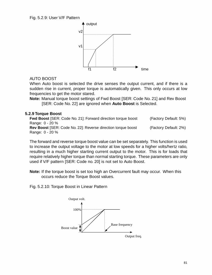
81
v2
v1
f1 f2 time
output
Fig. 5.2.9: User V/F Pattern
AUTO BOOSTWhen Auto boost is selected the drive senses the output current, and if there is asudden rise in current, proper torque is automatically given. This only occurs at lowfrequencies to get the motor stared.Note: Manual torque boost settings of Fwd Boost [SER: Code No. 21] and Rev Boost
[SER: Code No. 22] are ignored when Auto Boost is Selected.
5.2.9 Torque BoostFwd Boost [SER: Code No. 21]: Forward direction torque boost (Factory Default: 5%)Range: 0 - 20 %Rev Boost [SER: Code No. 22]: Reverse direction torque boost (Factory Default: 2%)Range: 0 - 20 %
The forward and reverse torque boost value can be set separately. This function is usedto increase the output voltage to the motor at low speeds for a higher volts/hertz ratio,resulting in a much higher starting current output to the motor. This is for loads thatrequire relatively higher torque than normal starting torque. These parameters are onlyused if V/F pattern [SER: Code no. 20] is not set to Auto Boost.
Note: If the torque boost is set too high an Overcurrent fault may occur. When thisoccurs reduce the Torque Boost values.
Fig. 5.2.10: Torque Boost in Linear Pattern
Output volt.
Output freq.
Boost value
100%
Base frequency

82
Fig. 5.2.11: Torque Boost in S-Curve Pattern
Output Voltage
Output Frequency
Base Frequency
Boost value
100%
5.2.10 Voltage ControlVolt Control [SER: Code No. 23]: Maximum drive output voltageRange: 0-110% (Factory Default: 100%)
Inverter output voltage can be adjusted to motor rated input voltage. This function isuseful when rated motor voltage is lower than the rated inverter output voltage. 110%means over-modulation in PWM causing a higher output voltage compared to 100% ofrated output voltage.
5.2.11 Motor Poles
Pole number [SER: Code No. 24]: Number of motor poles (Factory Default: 4)Range: 2 (3600 RPM)
4 (1800 RPM)6 (1200 RPM)8 (900 RPM)10 (720 RPM)12 (600 RPM)
Relate the syncronous speed of the motor to the number of poles and adjust the valueof Pole number [SER: Code No. 24] to match.
5.2.12 Brake Release
FST-freq. [SER: Code No. 25]: Brake Release Frequency (Factory Ddfault: 3.01 Hz)Range: 0.50 - SER 15 Hz.
This is the frequency at which the drive releases the brake. The drive allows time for themotor to build flux before ramping up the drive output and releasing the brake. SeeFigures 5.2.5 and 5.2.6 in Section 5.2.7 for a graphical representation.

83
5.2.13 Upload / Download from Keypad and Set Factory DefaultsPara read [SER: Code No. 26]: Read all parameters from drive to keypadRange: Yes (Factory Default: No)
No
Para write [SER: Code No. 27]: Write all parameters from keypad to driveRange: Yes (Factory Default: No)
No
By setting Para read [SER: Code No. 26] to Yes, all drive data, including fault history,will be uploaded to the Electronically Programmable Read Only Memory (EPROM) ofthe keypad. This can be a useful way to store drive status at the time of fault.By setting Part write [SER: Code No. 26] to Yes, all drive data stored in the keypad willbe downloaded to the drive. This can be a useful option when copying a set of parametersfrom one drive to another.
Para init [SER: Code No. 28]: Initialize all parameters with factory default settingsRange: Yes (Factory Default: No)
No
If set to Yes, the factory initial parameter settings will be downloaded to the drive.
5.2.14 Braking
Stop Mode [SER: Code No. 30]: Drive stop mode (Factory Default: Immediate stop)Range: Decel
DCBRImmediate stopAcc/Dec Abs
DECELRamp to Stop is the default value for traverse applications. The drive output rampsdown to a stop when the Run command is released. Not recommended for use withworm gear speed reducers. RAMP TO STOP IS NOT ADVISED FOR HOIST MOTION.
DCBRSee Section 5.3.8 for an explanation of this feature.
IMMEDIATE STOPImmediate Stop is the default value for hoist applications. The drive output turns offwhen the Run command is released.
ACC/DEC ABSWhen ACC/DEC ABS is selected the drive accelerates and decelerates for the amountof time set in Acc. Time [USE: Code No. 10] and Dec. Time [USE: Code No. 11] regardlessof the frequency the drive is at. If the drive is running at 60 Hz. it takes Dec. Time todecelerate to 0 Hz. If the drive is running at 30 Hz. it takes Dec. Time to decelerate to 0Hz.

84
Section 5.3: Advanced Level Functions
5.3.1 Drive ModeDrive mode [ADV: Code No. 01]: Only Manual mode is available for Hoist/CraneRange: Manual
AutoNOTE: Only Manual should be selected for Hoist / Crane applications.
5.3.2 Frequency Reference SourceFreq. set [ADV: Code No. 02]: Command frequency Source (Factory Default: Key)Range: Key
TerminalRS485/PLC
In order for the drive to receive its speed reference from an analog source or from aPLC instead of the keypad Freq. set [ADV: Code No. 02] must be adjusted. RS485input requires an optional input module.
5.3.3 Energy SaveEnergy save [ADV: Code No. 03]: Value for energy saving modeRange: 50 - 100 % (Factory Default: 80 %)
For fan and pump applications, not for hoist/crane.
5.3.4 User V/F Pattern (See Section 5.2.8 for ADV: Codes 04 - 11)
5.3.5 Analog Frequency ControlV-I mode [ADV: Code No. 12]: Analog input mode (Factory Default: Voltage)Range: Voltage
CurrentVolt+Curr
Filter gain [ADV: Code No. 13]: Analog input filter gain (Factory Default: 50 %)Range: 0 - 100 %
Analog gain [ADV: Code No. 14]: Analog input scaling (Factory Default: 100%)Range: 50 - 250 %
Analog bias [ADV: Code No. 15]: Analog input bias (Factory Default: 0.00%)Range: 0 - 100 %
Analog dir [ADV: Code No. 16]: Analog input polarity (Factory Default: Direct)Range: Direct
Invert
In order for the drive to receive its speed reference from an external source instead ofthe keypad Freq. Set [ADV: Code No. 02] must be set to Terminal. V-I Mode [ADV: CodeNo. 12] is used to select the analog frequency reference method. If a 0 ~ 10 VDC signalis the desired source of reference, then Voltage should be selected. If a 4 ~ 20 mAsignal is the source of reference, then Current should be selected. When both of thesignals are used, then Voltage+Current should be selected. See Fig. 5.3.1.
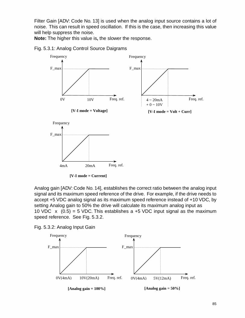
85
Filter Gain [ADV: Code No. 13] is used when the analog input source contains a lot ofnoise. This can result in speed oscillation. If this is the case, then increasing this valuewill help suppress the noise.Note: The higher this value is, the slower the response.
Fig. 5.3.1: Analog Control Source Daigrams
Frequency
Freq. ref.
F_max
0V(4mA) 10V(20mA)
[Analog gain = 100%]
Frequency
Freq. ref.
F_max
[Analog gain = 50%]
0V(4mA) 5V(12mA)
Frequency
Freq. ref.
F_max
0V 10V
[V-I mode = Voltage]
Frequency
Freq. ref.
F_max
[V-I mode = Volt + Curr]
Frequency
Freq. ref.
F_max
[V-I mode = Current]
4mA 20mA
4 ~ 20mA+ 0 ~ 10V
Analog gain [ADV: Code No. 14], establishes the correct ratio between the analog inputsignal and its maximum speed reference of the drive. For example, if the drive needs toaccept +5 VDC analog signal as its maximum speed reference instead of +10 VDC, bysetting Analog gain to 50% the drive will calculate its maximum analog input as10 VDC x (0.5) = 5 VDC. This establishes a +5 VDC input signal as the maximumspeed reference. See Fig. 5.3.2.
Fig. 5.3.2: Analog Input Gain
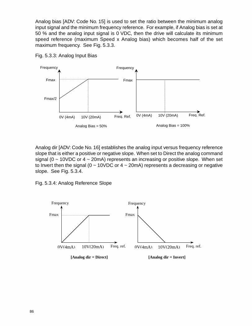
86
Analog bias [ADV: Code No. 15] is used to set the ratio between the minimum analoginput signal and the minimum frequency reference. For example, if Analog bias is set at50 % and the analog input signal is 0 VDC, then the drive will calculate its minimumspeed reference (maximum Speed x Analog bias) which becomes half of the setmaximum frequency. See Fig. 5.3.3.
Fig. 5.3.3: Analog Input Bias
Frequency Frequency
Fmax Fmax
Fmax/2
0V (4mA) 10V (20mA) 0V (4mA) 10V (20mA)Freq. Ref. Freq. Ref.
Analog Bias = 50% Analog Bias = 100%
Analog dir [ADV: Code No. 16] establishes the analog input versus frequency referenceslope that is either a positive or negative slope. When set to Direct the analog commandsignal (0 ~ 10VDC or 4 ~ 20mA) represents an increasing or positive slope. When setto Invert then the signal (0 ~ 10VDC or 4 ~ 20mA) represents a decreasing or negativeslope. See Fig. 5.3.4.
Fig. 5.3.4: Analog Reference Slope
Frequency
Freq. ref.
Fmax
0V(4mA) 10V(20mA)
[Analog dir = Direct]
Frequency
Freq. ref.
Fmax
[Analog dir = Invert]
0V(4mA) 10V(20mA)

87
5.3.6 Maximum / Minimum Operating Frequency
F-limit high [ADV: Code No. 18]: Maximum operating frequencyRange: ADV 19 Hz - SER 15 Hz. (Factory Default: 60.00 Hz)
F-limit low [ADV: Code No. 19]: Minimum operating frequencyRange: 0.00 - ADV 18 Hz. (Factory Default: 0.00 Hz)
The output frequency range of the drive is limited to the values set in Max Freq limit[ADV: Code No. 18] and Min Freq limit [ADV: Code No. 19]. See Fig. 5.3.5.
Fig. 5.3.5: Operational Maximum Frequency
Output Frequency
Command Frequency
50Hz
10Hz
Freq. ref.
Limited Frequency

88
5.3.7 Frequency to BypassFreq.-Jump [ADV: Code No. 20]: Selection of frequency jump functionRange: Yes (Factory Default: No)
NoFreq.-Jump 1f [ADV: Code No. 21]: Jump (bypass) frequency 1Range: 0 - SER 15 Hz. (Factory Default: 10.00 Hz.)
Freq.-Jump 2f [ADV: Code No. 22]: Jump (bypass) frequency 2
Range: 0 - SER 15 Hz. (Factory Default: 20.00 Hz.)
Freq.-Jump 3f [ADV: Code No. 23]: Jump (bypass) frequency 3Range: 0 - SER 15 Hz. (Factory Default: 30.00 Hz.)
Freq. band [ADV: Code No. 24]: Jump (bypass) frequency bandwidthRange: 0.00 - 30.00 Hz. (Factory Default: 5.00 Hz.)
Undesirable resonance and vibration on the motor shaft of the hoist or crane couldoccur within a certain frequency range due to the structure of the machine. This frequencybypass function is used to lock that frequency band out of the operation. Most of thetime, this phenomenon occurs only at a specific frequency. The jump frequency alsohas its own bandwidth. This is a span of the particular bypass frequency selected. SeeFig. 5.3.6.
Fig. 5.3.6: Frequency Bypass
timeFreq.-Jump 1 [ADV: Code No. 21]
Freq. Band[ADV: Code No. 24]
Output freq.
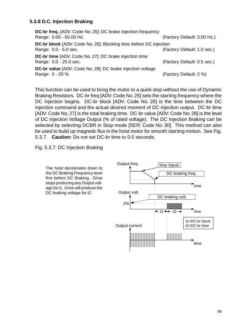
89
5.3.8 D.C. Injection Braking
DC-br freq. [ADV: Code No. 25]: DC brake injection frequencyRange: 0.00 - 60.00 Hz. (Factory Default: 3.00 Hz.)
DC-br block [ADV: Code No. 26]: Blocking time before DC injectionRange: 0.0 - 5.0 sec. (Factory Default: 1.0 sec.)
DC-br time [ADV: Code No. 27]: DC brake injection timeRange: 0.0 - 25.0 sec. (Factory Default: 0.5 sec.)
DC-br value [ADV: Code No. 28]: DC brake injection voltageRange: 0 - 20 % (Factory Default: 2 %)
This function can be used to bring the motor to a quick stop without the use of DynamicBraking Resistors. DC-br freq [ADV: Code No. 25] sets the starting frequency where theDC Injection begins. DC-br block [ADV: Code No. 26] is the time between the DCInjection command and the actual desired moment of DC injection output. DC-br time[ADV: Code No. 27] is the total braking time. DC-br value [ADV: Code No. 28] is the levelof DC Injection Voltage Output (% of rated voltage). The DC Injection Braking can beselected by selecting DCBR in Stop mode [SER: Code No. 30]. This method can alsobe used to build up magnetic flux in the hoist motor for smooth starting motion. See Fig.5.3.7. Caution: Do not set DC-br time to 0.0 seconds.
Fig. 5.3.7: DC Injection Braking
The hoist decelerates down tothe DC Braking Frequency levelfirst before DC Braking. Drivestops producing any Output volt-age for t1. Drive will produce theDC braking voltage for t2.
time
t1 t2
StopOutput freq.
Output volt.
Output current
2%
DC braking freq.
DC braking volt.
tim
tim
t1=DC-br blkt2=DC-br time
Stop Signal
time
timetime
t1=DC-br blockt2=DC-br time
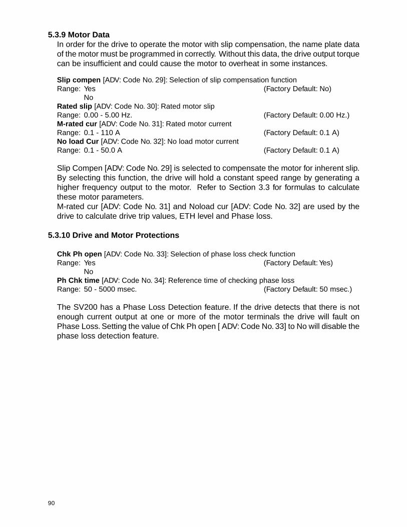
90
5.3.9 Motor DataIn order for the drive to operate the motor with slip compensation, the name plate dataof the motor must be programmed in correctly. Without this data, the drive output torquecan be insufficient and could cause the motor to overheat in some instances.
Slip compen [ADV: Code No. 29]: Selection of slip compensation functionRange: Yes (Factory Default: No)
NoRated slip [ADV: Code No. 30]: Rated motor slipRange: 0.00 - 5.00 Hz. (Factory Default: 0.00 Hz.)M-rated cur [ADV: Code No. 31]: Rated motor currentRange: 0.1 - 110 A (Factory Default: 0.1 A)No load Cur [ADV: Code No. 32]: No load motor currentRange: 0.1 - 50.0 A (Factory Default: 0.1 A)
Slip Compen [ADV: Code No. 29] is selected to compensate the motor for inherent slip.By selecting this function, the drive will hold a constant speed range by generating ahigher frequency output to the motor. Refer to Section 3.3 for formulas to calculatethese motor parameters.M-rated cur [ADV: Code No. 31] and Noload cur [ADV: Code No. 32] are used by thedrive to calculate drive trip values, ETH level and Phase loss.
5.3.10 Drive and Motor Protections
Chk Ph open [ADV: Code No. 33]: Selection of phase loss check functionRange: Yes (Factory Default: Yes)
NoPh Chk time [ADV: Code No. 34]: Reference time of checking phase lossRange: 50 - 5000 msec. (Factory Default: 50 msec.)
The SV200 has a Phase Loss Detection feature. If the drive detects that there is notenough current output at one or more of the motor terminals the drive will fault onPhase Loss. Setting the value of Chk Ph open [ ADV: Code No. 33] to No will disable thephase loss detection feature.

91
Retry number [ADV: Code No. 35]: Number of retries when drive faultsRange: 0 - 10 (Factory Default: 0)Retry time [ADV: Code No. 36]: Waiting time before retryingRange: 0.0 - 10.0 sec. (Factory Default: 1.0 sec.)Retry mode [ADV: Code No. 37]: Mode of fault retryRange: Retry 0 (Factory Default: Retry 0)
All TripsLV + Retry 0LV + All Trips
These functions are used so the drive can reset itself automatically from various drivefaults (Over Voltage, Over Current, Ground Fault, Torque Limit Fault, etc.) except UnderVoltage or BX fault. The operator can set the maximum number of auto-restart trialsthrough Retry number [ADV: Code No. 35], and Retry Time [ADV: Code No. 36], see Fig.5.3.8. The auto-restart works in conjunction with the Speed Search Mode, see Section5.3.14.
Fig. 5.3.8: Retry Mode
OL level [ADV: Code No. 40]:Overload warning levelRange: 30 - 150% (Factory Default: 150%)
OL Time [ADV: Code No. 41]: Overload warning delay timeRange: 1.0 - 30.0 sec. (Factory Default: 10.0 sec.)
This function is used to provide a motor overload warning. When the output current ofthe drive has reached the value of OL level [ADV: Code No. 40] for an amount of timeequal to OL Time [ADV: Code No. 41], a designated multi-function output terminal willbe turned on. For an Overload warning to occur, a multi-function output must be set toOL, this function does not cause the drive to fault. See Section 5.2.4.
Output freq. [Hz.]
t t t = Retry time[ADV: Code No. 36]
time
First Fault Second Fault
First Retry Second Retry
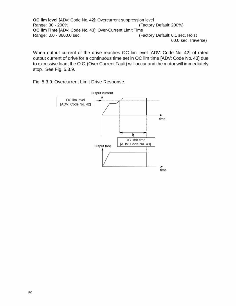
92
OC lim level [ADV: Code No. 42]: Overcurrent suppression levelRange: 30 - 200% (Factory Default: 200%)OC lim Time [ADV: Code No. 43]: Over-Current Limit TimeRange: 0.0 - 3600.0 sec. (Factory Default: 0.1 sec. Hoist
60.0 sec. Traverse)
When output current of the drive reaches OC lim level [ADV: Code No. 42] of ratedoutput current of drive for a continuous time set in OC lim time [ADV: Code No. 43] dueto excessive load, the O.C. (Over Current Fault) will occur and the motor will immediatelystop. See Fig. 5.3.9.
Fig. 5.3.9: Overcurrent Limit Drive Response.
Output current
time
OC lim level [ADV: Code No. 42]
Output freq.
time
OC limit time [ADV: Code No. 43]

93
ETH Select [ADV: Code No. 44]: Mode of electronic thermal protectionRange: None (Factory Default: None)
Const TorqVari Torq
ETH level [ADV: Code No. 45]: ETH LevelRange: 30 - 150% (Factory Default: 150%)
Motor Type [ADV: Code No. 46]: Type of motorRange: General (Factory Default: General)
Special
This function is used to compensate for excessive motor heat generated during longterm low frequency operation. This is especially true if the capacity of the hoist motor islower than that of the inverter. To prevent the motor from overheating, the ETH level[ADV: Code No. 45] must be set according to the provided formula.
ETH level(%) = K x (Motor rated current / Inverter rated current) x 100%( K = 1.0 for 50Hz Input Power, K = 1.1 for 60 Hz Input Power)
Once the ETH level is found, then the Motor Type [ADV: Code No. 46] of the hoist mustbe determined. There are two electronic thermal motor characteristics, one is Generalpertaining to a standard AC induction motor, the other is Special for a special motorcontaining a blower. Once the correct values are programmed, the drive will determinethe ETH time from a formula using M-rated cur [ADV: Code No. 31] and ETH level.
5.3.11 Stall Prevention
Stall mode [ADV: Code No. 38]: Stall prevention mode selectionRange: None (Factory Default: None Hoist
Acc Acc Traverse)SteadyAcc+SteadyDecAcc+DecDec+SteadyAcc+Dec+Steady
Stall level [ADV: Code No. 39]: Stall prevention levelRange: 30 - 150% (Factory Default: 150%)
NOTE: DO NOT USE STALL PREVENTION ON HOIST MOTION.GREAT CARE SHOULD BE EXERCISED WHEN SELECTING DECELERATION,“Dec”, AS A STALL PREVENTION MODE WHEN USING A DYNAMIC BRAKINGRESISTOR.
These functions are used to prevent the traverse faults that occur due to load fluctuationby reducing the inverter output frequency until the motor current level decreases belowStall level [ADV: Code No. 39]. Once the motor current level satisfies the value of Stalllevel, then the drive will increase its output frequency to its set point.

94
ACCELERATIONIf the output current of the drive has reached Stall level during drive acceleration, thedrive will stop accelerating until the current level is reduced below Stall level before itresumes acceleration to a set frequency command. See Fig. 5.3.10.
STEADY SPEEDIf the output current of the drive has reached the Stall level during a steady speedperiod, due to load fluctuation, the drive will then reduce its output frequency until theoutput current level is reduced below Stall level. The drive will then increase its outputfrequency to a set frequency command. See Fig. 5.3.11.
DECELERATIONIf the DC BUS voltage reaches the O.V. fault level (800 VDC for the 460 VAC class,400VDC for the 230 VAC class) during deceleration, the drive will stop furtherdeceleration until DC Bus voltage drops below the fault level. See Fig. 5.3.12.
Fig. 5.3.10: Stall Prevention during Acceleration
Fig. 5.3.11: Stall Prevention during Steady Speed
Output current
Output freq.
Stall prevention level [ADV: Code No. 39]
time
time
Output current
Output freq.
Stall prevention level [ADV: Code No. 39]
Dec. ramp Acc. ramp
time
time
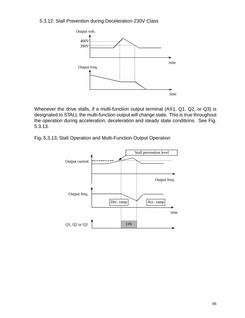
95
5.3.12: Stall Prevention during Deceleration-230V Class
Whenever the drive stalls, if a multi-function output terminal (AX1, Q1, Q2, or Q3) isdesignated to STALL the multi-function output will change state. This is true throughoutthe operation during acceleration, deceleration and steady state conditions. See Fig.5.3.13.
Fig. 5.3.13: Stall Operation and Multi-Function Output Operation
Output freq.
Output volt.
time
400V 390V
time
Q1, Q2 or Q3
Output freq.
ON
Stall prevention level
Output freq.
Acc. ramp
time
Output current
Dec. ramp
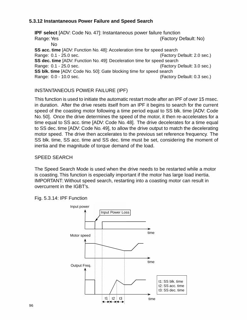
96
5.3.12 Instantaneous Power Failure and Speed Search
IPF select [ADV: Code No. 47]: Instantaneous power failure functionRange: Yes (Factory Default: No)
NoSS acc. time [ADV: Function No. 48]: Acceleration time for speed searchRange: 0.1 - 25.0 sec. (Factory Default: 2.0 sec.)SS dec. time [ADV: Function No. 49]: Deceleration time for speed searchRange: 0.1 - 25.0 sec. (Factory Default: 3.0 sec.)SS blk. time [ADV: Code No. 50]: Gate blocking time for speed searchRange: 0.0 - 10.0 sec. (Factory Default: 0.3 sec.)
INSTANTANEOUS POWER FAILURE (IPF)
This function is used to initiate the automatic restart mode after an IPF of over 15 msec.in duration. After the drive resets itself from an IPF it begins to search for the currentspeed of the coasting motor following a time period equal to SS blk. time [ADV: CodeNo. 50]. Once the drive determines the speed of the motor, it then re-accelerates for atime equal to SS acc. time [ADV: Code No. 48]. The drive decelerates for a time equalto SS dec. time [ADV: Code No. 49], to allow the drive output to match the deceleratingmotor speed. The drive then accelerates to the previous set reference frequency. TheSS blk. time, SS acc. time and SS dec. time must be set, considering the moment ofinertia and the magnitude of torque demand of the load.
SPEED SEARCH
The Speed Search Mode is used when the drive needs to be restarted while a motoris coasting. This function is especially important if the motor has large load inertia.IMPORTANT: Without speed search, restarting into a coasting motor can result inovercurrent in the IGBT’s.
Fig. 5.3.14: IPF Function
Input power
time
time
time
Motor speed
Output Freq.
t1 t2 t3
t1: H37t2: H35t3: H36
InputPower Loss
t1: SS blk. timet2: SS acc. timet3: SS dec. time
Input Power Loss

97
5.3.13 Restart After Reset
RST restart [ADV: Function No. 51]: Selection of reset restart functionRange: Yes (Factory Default: No)
No
When RST restart [ADV: Function No. 51] is set to Yes, the drive can be selected to haveitself initiate auto-restart mode after the manual reset. If this parameter is set to No,then the drive needs to receive the RUN command after the manual reset.
Fig. 5.3.15: Reset Restart Inactive
When RST restart function isNo, F (Forward) or R (Reverse)pendant buttons must be releasedthen pushed again after a manualreset in order to run the drive again.
INPUT POWER DETECTED AUTO-RESTART
Power on st [ADV: Function No. 52]: Selection of power-on restart functionRange: Yes (Factory Default: No)
No
When either F (UP/FORWARD) input terminal or R (DOWN/REVERSE) input terminalis energized and the input power is restored, the drive will initiate the auto-restartautomatically when Power on st is set to Yes. See Figs. 5.3.16 and 5.3.17.
Output Freq.[Hz]
FX-CM
Reset
ON ON
ON
Trip
No Effect Effect
time
When Power on st is setto No, the drive will not runat the time of the Power UpSequence. An external orkeypad Run Commandmust be given in order torestart the drive.
Trip
F (UP/FORWARD)
Input Power
Input Power ON
Output Freq.
F (UP/FORWARD)
ON ONtime
time
time
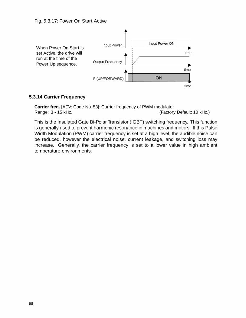
98
Input Power
Output Frequency
F (UP/FORWARD) ON
Input Power ON
time
time
time
Fig. 5.3.17: Power On Start Active
When Power On Start isset Active, the drive willrun at the time of thePower Up sequence.
5.3.14 Carrier Frequency
Carrier freq. [ADV: Code No. 53]: Carrier frequency of PWM modulatorRange: 3 - 15 kHz. (Factory Default: 10 kHz.)
This is the Insulated Gate Bi-Polar Transistor (IGBT) switching frequency. This functionis generally used to prevent harmonic resonance in machines and motors. If this PulseWidth Modulation (PWM) carrier frequency is set at a high level, the audible noise canbe reduced, however the electrical noise, current leakage, and switching loss mayincrease. Generally, the carrier frequency is set to a lower value in high ambienttemperature environments.

99
5.3.15 Two Motor Applications
Drive freq. 2 [ADV: Code No. 54]: Motor no. 2 frequency Range:0 - SER 15 Hz. (Factory Default: 0 Hz.)Acc. time 2 [ADV: Code No. 55]: Motor no. 2 acceleration timeRange: 0 - 6000.0 sec. (Factory Default: 5.0 sec.)Dec. time 2 [ADV: Code No. 56]: Motor no. 2 deceleration timeRange: 0 - 6000.0 sec. (Factory Default: 10.0 sec.)Freq. base 2 [ADV: Code No. 57]: Motor no. 2 base frequencyRange: 40 - SER 15 Hz. (Factory Default: 60.00 Hz.)V/F pattern 2 [ADV: Code No. 58]: Motor no. 2 V/F patternRange: Linear (Factory Default: Linear)
2.0UserAuto boost
Fwd boost [ADV: Code No. 59]: Motor no. 2 forward boostRange: 0 - 20% (Factory Default: 2%)Rev boost [ADV: Code No. 60]: Motor no. 2 reverse boostRange: 0 - 20% (Factory Default: 2%)Stall level 2 [ADV: Code No. 61]: Motor no. 2 stall levelRange: 30 - 150% (Factory Default: 150%)ETH level 2 [ ADV: Code No. 62]: Motor no. 2 ETH levelRange: 30 - 150% (Factory Default: 150%)
These functions are for controlling a second motor with the drive and are not available.
5.3.16 Closed Loop Speed Control
PI control [ADV: Code No. 63]: Selection of internal PI functionRange: None (Factory Default: None)
Steady - NSteady - R
P-gain [ADV: Code No. 64]: P gain of internal PI controllerRange: 0 - 30000 (Factory Default: 10)I-gain [ADV: Code No. 65]: I gain of internal PI controller Range:0 - 30000 (Factory Default: 50)PI-FB offset [ADV: Code No. 66]: Offset (bias) of PI feedback signalRange: 0 - 50% (Factory Default: 0%)PI-FB scale [ADV: Code No. 67]: Scaling factor of PI feedback signalRange: 1 - 250% (Factory Default: 100%)
The drive has a built in Proprtional - Integral closed loop controller. It requires an analogfeedback reference to control the motor speed. Consult the factory for more information.

100
5.3.17 Rotation Direction Prevention
Run Prev. [ADV: Code No. 68]: Prevention of one direction of rotationRange: None (Factory Default: None)
Reverse Prev.Forward Prev.
This function will prevent the drive from turning the motor in one or the other direction.
5.3.18 Jog Frequency
Jog frequency [ADV: Code No. 69]: Jogging frequencyRange: 0 - SER 15 Hz. (Factory Default: 30.00 Hz.)
The frequency the drive sends to the motor when using the jog command.
5.3.19 Output Current, Voltage and Frequency
Analog meter [ADV: Code No. 70]: Mode of analog meterRange: Voltage (Factory Default: Voltage)
CurrentAnalog adjust [ADV: Code No. 71]: Adjustment of analog meterRange: 0 - 120% (Factory Default: 100%)FM adjust [ADV: Code No. 72]: Adjustment of frequency meterRange: 0 - 120% (Factory Default: 100%)
Drive has an LM terminal and an FM terminal which can be programmed to generateeither drive voltage or current output (LM terminal) and drive output frequency (FMterminal) measurements in 0 ~ 10VDC pulse signal. See Fig. 5.3.18, which showsfrequency meter, but the LM terminal works the same. The measurement selection fordrive output voltage or current can be programmed in Analog meter [ADV: Code No. 70].When a different ratio between LM, or FM, output and actual drive voltage or currentmeasurement is required, the value of Analog adjust [ADV: Code No. 71] for LM and FMadjust [ADV: Code No. 72] for FM can be set at values which will meet the ratiorequirements.
See Fig. 5.3.18: Multi-meter OutputOutput freq.
10V(peak)
FM Average 0~10V
f time
Frequency meter frequency(f) = (Output frequency / Maximum frequency) * 1.8 kHzDuty (%) = (Output frequency / Maximum frequency) * 2/3Frequency meter voltage = (Output frequency / Maximum frequency) * 10V

101
5.3.20 Frequency Detection
FDT-freq. [ADV: Code No. 73] Frequency detection levelRange: 0.50 - SER 15 Hz. (Factory Default: 60.0 Hz)FDT-band [ADV: Code No. 74] Frequency detection bandRange: 0.00 - 30.0 Hz. (Factory Default: 1.00 Hz)
This function is used to operate one of the multi-function outputs. If a Multi-FunctionOutput is programmed for FDT_HI the output signal is set once the drive reaches FDTfrequency [ADV: Code No. 73], and resets when the drive frequency falls below FDTfrequency less FDT band [ADV: Code No. 74]. See Fig. 5.3.19. If a Multi-FunctionOutput is programmed for FDT_PULSE the output pulses as the increasing frequencypasses through FDT frequency and again as the decreasing frequency passes throughFDT frequency less FDT band. If a Multi-Function Output is programmed for FDT_BANDthe output sets when the drive output is at the requested frequency plus or minus theFDT band. See Section 5.2.4 for more information regarding the Multi-function output.
Fig. 5.3.19 FDT_HI Functions Diagram
Multi-function Output
Output freq. time
ON
FDT Frequency[ADV: Code No. 73]
FDT band[ADV: Code No. 74]
5.3.21 Speed Display Scaling Factor
Mul factor [ADV: Code No. 75] Scaling factor for USE 04 displayRange: 0 - 999 (Factory Default: 100)Div factor [ADV: Code No. 76] Scaling factor for USE 04 displayRange: 1 - 999 (Factory Default: 100)
This function is used to scale the display Speed [USE: Code No. 04]. The values in Mulfactor [ADV: Code No. 75] and Div factor [ADV: Code No. 76] can be adjusted to accountfor gear ratios.
5.3.22 LED Check
LED check [ADV: Code No. 77] This function is not used.
102
5.3.23 Option Card
Option [ADV: Code No. 78]: Option (Interface) cardRange: None (Factory Default: None)
RS485PGDI/DAPLCCAN
Inv. Number [ADV: Code No. 79]: RS 485 Inverter addressRange: 1 - 32 (Factory Default: 1)Baud Rate [ADV: Code No. 80]: RS 485 baud rateRange: 1200 bps (Factory Default: 9600 bps)
2400 bps4800 bps9600 bps19200 bps
PG slip freq. [ADV: Code No. 81]: rated slip of motorRange: 0.00 - 5.00 Hz. (Factory Default: 2.00 Hz.)PG P gain [ADV: Code No. 82]: P gain of PG optionRange: 1 - 255 (Factory Default: 100)PG I gain [ADV: Code No. 83]: I gain of PG optionRange: 1 - 255 (Factory Default: 10)Enc. signal [ADV: Code No. 84]: Encoder typeRange: A + B (Factory Default: A + B)
A onlyEnc pulse [ADV: Code No. 85]: Pulses per revolutionRange: 360 (Factory Default: 1024)
500512100010242000204840004096
DI mode [ADV: Code No. 86]: Mode of digital input option cardRange: None (Factory Default: Freq.)
Freq.DA mode [ADV: Code No. 87]: Mode of digital output option cardRange: Freq. (Factory Default: Freq.)
VoltageCurrent
Remote T. Out [ADV: Code No. 88]: RS 485/PLC/CAN optionRange: 0.0 - 600.0 sec. (Factory Default: 0.0 sec.)
These functions relate to a set of option cards for the drive. If more information isrequired about these functions please consult the factory.
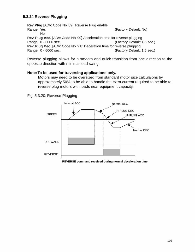
103
5.3.24 Reverse Plugging
Rev Plug [ADV: Code No. 89]: Reverse Plug enableRange: Yes (Factory Default: No)
NoRev. Plug Acc. [ADV: Code No. 90] Acceleration time for reverse pluggingRange: 0 - 6000 sec. (Factory Default: 1.5 sec.)Rev. Plug Dec. [ADV: Code No. 91]: Deceration time for reverse pluggingRange: 0 - 6000 sec. (Factory Default: 1.5 sec.)
Reverse plugging allows for a smooth and quick transition from one direction to theopposite direction with minimal load swing.
Note: To be used for traversing applications only.Motors may need to be oversized from standard motor size calculaions byapproximately 50% to be able to handle the extra current required to be able toreverse plug motors with loads near equipment capacity.
Fig. 5.3.20: Reverse Plugging
Normal ACC Normal DEC
Normal DEC
R-PLUG ACC SPEED
FORWARD
REVERSE
REVERSE command received during normal deceleration time
R-PLUG DEC

104
This page intentionally left blank.
105
Chapter 6: Maintenance
Section 6.1: Maintenance
Section 6.2: Precautions
Section 6.3: Routine Inspection
Section 6.4: Visual Inspection

106
6.1 Maintenance
SV200 Series can be influenced by temperature, humidity, and vibration. To avoid anypossible uncertainty, the drive must be installed and maintained properly by trainedpersonnel.
6.2 Precaution
Only certified personnel familiar with the equipment are permitted to install, operateand maintain the drive.
Observe the Charge LED on the drive to be sure of complete power dissipation.
The output voltage of your SV200 drive can only be measured by a rectifier voltagemeter(such as an RMS meter). Other instruments such as a digital meter will read anincorrect value due to the high switching PWM frequency.
6.3 Routine InspectionCheck Input-Line Voltage to the drive for any fluctuation.Check the Cooling Fan. If there is any abnormal noise, replace.Check for any physical vibration to the drive.Check the temperature for any overheating.
6.4 Visual InspectionAny loose screws, nuts, or wires?➝➝➝➝➝ Tighten or replace.
Any deposit of dust or foreign material in the AC Drive or Cooling Fan?➝➝➝➝➝ Clean off the dust or foreign material.
Are any connectors disconnected from printed circuit boards?➝➝➝➝➝ Re-insert the connector.
Inspect for corrosion.➝➝➝➝➝ Clean where possible or replace.

107
AppendixAppendix Fig. 1: Sample Traverse Wiring Diagram
Appendix Fig. 2: Sample Hoist Wiring Diagram with Analog Control
Traverse Wiring Diagram Example: P5 Input [SER: Code No. 08] set for LSW Low Spd.
Hoist Wiring Diagram Example: Freq. set [ADV: Code No. 02] set for Terminal.

108
Appendix Fig. 3: 2 Speed Control
Appendix Fig. 4: 2 Step Infinitely Variable Control
Appendix Fig. 5: 3 Speed Control
SPEED
Spd Sel 2
F UP / FORWARD
Spd Sel 3
SPEED
2 SPD SEL 2
F UP / FORWARD
SPEED
2 SPD SEL 2
F UP / FORWARD

109
Appendix Fig. 6: 3 Step Infinitely Variable Control
Appendix Fig. 7: 5 Speed Control
F - UP/FORWARD
SPD SEL 2
SPD SEL 3
SPEED
SPEED
Spd Sel 2
F UP / FORWARD
Spd Sel 3
Spd Sel 4
Spd Sel 5

110
NOTES

111
NOTES

112
May 2000 COPYRIGHT 2000 Columbus McKinnon Corporation 117463-2
WARRANTYWARRANTY AND LIMITATION OF REMEDY AND LIABILITY
A. Seller warrants that its products and parts, when shipped,and its work (including installation, construction and start-up),when performed, will meet applicable specifications, will be ofgood quality and will be free from defects in material andworkmanship. All claims for defective products or parts underthis warranty must be made in writing immediately upondiscovery and, in any event, within two (2) years (or asotherwise provided) from shipment of the applicable item unlessSeller specifically assumes installation, construction or start-up responsibility. All claims for defective products or partswhen Seller specifically assumes installation, construction orstart-up responsibility, and all claims for defective work mustbe made in writing immediately upon discovery and, in anyevent, within two (2) years (or as otherwise provided) fromcompletion of the applicable work by Seller, provided, however,all claims for defective products and parts must be made inwriting no later than thirty (30) months after shipment. Defectiveitems must be held for Seller’s inspection and returned to theoriginal f.o.b. point upon request. THE FOREGOING ISEXPRESSLY IN LIEU OF ALL OTHER WARRANTIESWHATSOEVER, EXPRESS, IMPLIED AND STATUTORY,INCLUDING, WITHOUT LIMITATION, THE IMPLIEDWARRANTIES OF MERCHANTABILITY AND FITNESS.
B. Upon Buyer’s submission of a claim as provided above andits substantiation, Seller shall, at its option, either (i) repair orreplace its product, part or work at either the original f.o.b.point of delivery or at Seller’s authorized service station nearestBuyer or (ii) refund an equitable portion of the purchase price.
C. This warranty is contingent upon Buyer’s proper maintenanceand care of Seller’s products, and does not extend to normalwear and tear. Seller reserves the right to void warranty inevent of Buyer’s use of inappropriate materials in the courseof repair or maintenance, or if Seller’s products have beendismantled prior to submission to Seller for warranty inspection.
D. The foregoing is Seller’s only obligation and Buyer’s exclusiveremedy for breach of warranty, and is Buyer’s exclusive remedyhereunder by way of breach of contract, tort, strict liability orotherwise. In no event shall Buyer be entitled to or Seller liablefor incidental or consequential damages. Any action for breachof this warranty must be commenced within two (2) years (oras otherwise provided) after the cause of action has accrued.
414 W. BROADWAY AVE.MUSKEGON, MI 49443-0769
Phone: 877 226-6278 (toll free)Fax: 231 733-3223
™
![Rainbow Heart - artecy.com · 7777777 777777777 7777777777777 ooooooo 77777 7777777 7777777777777 oooooo]]]]] ddd ddd ddd ddd ddd ™™™™™™™™™™™ ™™™™™™™™™™™™™™™™™](https://static.fdocuments.in/doc/165x107/5f4a4ec8ec2fea16bc048a6a/rainbow-heart-7777777-777777777-7777777777777-ooooooo-77777-7777777-7777777777777.jpg)