Spacecraft and Aircraft Dynamics - Lecture 9: 6DOF Equations of
24
Spacecraft and Aircraft Dynamics Matthew M. Peet Illinois Institute of Technology Lecture 9: 6DOF Equations of Motion
Transcript of Spacecraft and Aircraft Dynamics - Lecture 9: 6DOF Equations of
Spacecraft and Aircraft Dynamics
Matthew M. PeetIllinois Institute of Technology
Lecture 9: 6DOF Equations of Motion
Aircraft DynamicsLecture 9
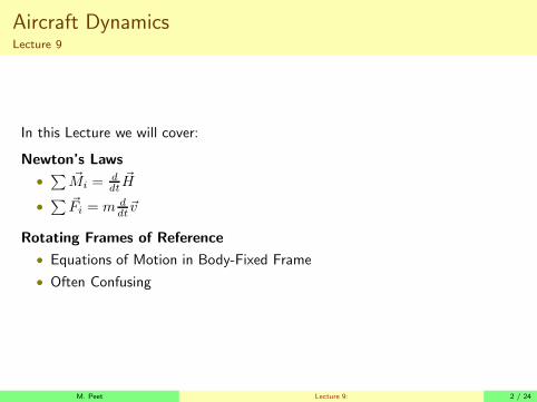
In this Lecture we will cover:
Newton’s Laws
•
∑ ~Mi =ddt~H
•
∑ ~Fi = m ddt~v
Rotating Frames of Reference
• Equations of Motion in Body-Fixed Frame
• Often Confusing
M. Peet Lecture 9: 2 / 24

Review: Coordinate RotationsPositive Directions
If in doubt, use the right-hand rules.
Figure: Positive Directions
Figure: Positive Rotations
M. Peet Lecture 9: 3 / 24
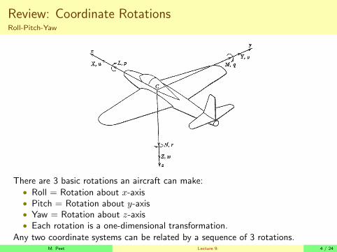
Review: Coordinate RotationsRoll-Pitch-Yaw
There are 3 basic rotations an aircraft can make:• Roll = Rotation about x-axis• Pitch = Rotation about y-axis• Yaw = Rotation about z-axis• Each rotation is a one-dimensional transformation.
Any two coordinate systems can be related by a sequence of 3 rotations.M. Peet Lecture 9: 4 / 24

Review: Forces and MomentsForces
These forces and moments have standard labels. The Forces are:
X Axial Force Net Force in the positive x-directionY Side Force Net Force in the positive y-directionZ Normal Force Net Force in the positive z-direction
M. Peet Lecture 9: 5 / 24

Review: Forces and MomentsMoments
The Moments are called, intuitively:
L Rolling Moment Net Moment in the positive p-directionM Pitching Moment Net Moment in the positive q-directionN Yawing Moment Net Moment in the positive r-direction
M. Peet Lecture 9: 6 / 24
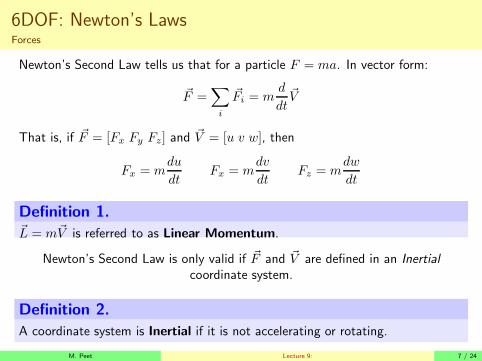
6DOF: Newton’s LawsForces
Newton’s Second Law tells us that for a particle F = ma. In vector form:
~F =∑
i
~Fi = md
dt~V
That is, if ~F = [Fx Fy Fz] and ~V = [u v w], then
Fx = mdu
dtFx = m
dv
dtFz = m
dw
dt
Definition 1.~L = m~V is referred to as Linear Momentum.
Newton’s Second Law is only valid if ~F and ~V are defined in an Inertial
coordinate system.
Definition 2.
A coordinate system is Inertial if it is not accelerating or rotating.
M. Peet Lecture 9: 7 / 24

Newton’s LawsMoments
Using Calculus, this concept can be extended to rigid bodies by integration overall particles.
~M =∑
i
~Mi =d
dt~H
Definition 3.
Where ~H =∫
(~rc × ~vc)dm is the angular momentum.
Angular momentum of a rigid body can be found as
~H = I~ωI
where ~ωI = [p, q, r]T is the angular rotation vector of the body about thecenter of mass.
• p is rotation about the x-axis.
• q is rotation about the y-axis.
• r is rotation about the z-axis.
• ωI is defined in an Inertial Frame.
The matrix I is the Moment of Inertia Matrix.M. Peet Lecture 9: 8 / 24

Newton’s LawsMoment of Inertia
The moment of inertia matrix is defined as
I =
Ixx −Ixy −Ixz−Iyx Iyy −Iyz−Izx −Izy Izz
Ixy = Iyx =
∫ ∫ ∫
xydm Ixx =
∫ ∫ ∫
(
y2 + z2)
dm
Ixz = Izx =
∫ ∫ ∫
xzdm Iyy =
∫ ∫ ∫
(
x2 + z2)
dm
Iyz = Izy =
∫ ∫ ∫
yzdm Izz =
∫ ∫ ∫
(
x2 + y2)
dm
So
Hx
Hy
Hz
=
Ixx −Ixy −Ixz−Iyx Iyy −Iyz−Izx −Izy Izz
pIqIrI
where pI , qI and rI are the rotation vectors as expressed in the inertial framecorresponding to x-y-z.
M. Peet Lecture 9: 9 / 24

Moment of InertiaExamples:
Homogeneous Sphere
Isphere =2
5mr2
1 0 00 1 00 0 1
Ring
Iring = mr2
1
20 0
0 1
20
0 0 1
M. Peet Lecture 9: 10 / 24

Moment of InertiaExamples:
Homogeneous Disk
Idisk =1
4mr2
1 + 1
3
hr2
0 00 1 + 1
3
hr2
00 0 1
2
F/A-18
I =
23 0 2.970 15.13 0
2.97 0 16.99
kslug − ft2
M. Peet Lecture 9: 11 / 24
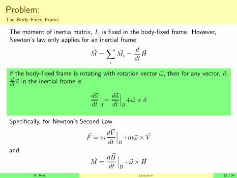
Problem:The Body-Fixed Frame
The moment of inertia matrix, I, is fixed in the body-fixed frame. However,Newton’s law only applies for an inertial frame:
~M =∑
i
~Mi =d
dt~H
If the body-fixed frame is rotating with rotation vector ~ω, then for any vector, ~a,ddt~a in the inertial frame is
d~a
dt
∣
∣
∣
I=d~a
dt
∣
∣
∣
B+~ω × ~a
Specifically, for Newton’s Second Law
~F = md~V
dt
∣
∣
∣
B+m~ω × ~V
and
~M =d ~H
dt
∣
∣
∣
B+~ω × ~H
M. Peet Lecture 9: 12 / 24
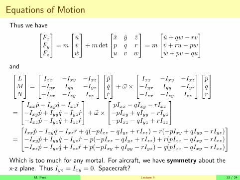
Equations of Motion
Thus we have
Fx
Fy
Fz
= m
uvw
+m det
x y zp q ru v w
= m
u+ qw − rvv + ru − pww + pv − qu
and
LMN
=
Ixx −Ixy −Ixz−Iyx Iyy −Iyz−Izx −Izy Izz
pqr
+ ~ω ×
Ixx −Ixy −Ixz−Iyx Iyy −Iyz−Izx −Izy Izz
pqr
=
Ixxp− Ixy q − Ixz r−Ixy p+ Iyy q − Iyz r−Ixz p− Iyz q + Izz r
+ ~ω ×
pIxx − qIxy − rIxz−pIxy + qIyy − rIyz−pIxz − qIyz + rIzz
=
Ixxp− Ixy q − Ixz r + q(−pIxz − qIyz + rIzz)− r(−pIxy + qIyy − rIyz)−Ixyp+ Iyy q − Iyz r − p(−pIxz − qIyz + rIzz) + r(pIxx − qIxy − rIxz)−Ixz p− Iyz q + Izz r + p(−pIxy + qIyy − rIyz)− q(pIxx − qIxy − rIxz)
Which is too much for any mortal. For aircraft, we have symmetry about thex-z plane. Thus Iyz = Ixy = 0. Spacecraft?
M. Peet Lecture 9: 13 / 24

Equations of MotionReduced Equations
With Ixy = Iyz = 0, we have, in summary:
Fx
Fy
Fz
= m
u+ qw − rvv + ru− pww + pv − qu
and
LMN
=
Ixxp− Ixz r − qpIxz + qrIzz − rqIyyIyy q + p2Ixz − prIzz + rpIxx − r2Ixz−Ixz p+ Izz r + pqIyy − qpIxx + qrIxz
Right now,
• Translational variables (u,v,w) depend on rotational variables (p,q,r).• Rotational variables (p,q,r) do not depend on translational variables(u,v,w).
I For aircraft, however, Moment forces (L,M,N) depend on rotational andtranslational variables.M. Peet Lecture 9: 14 / 24
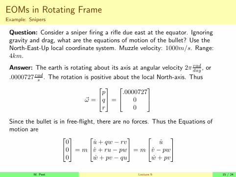
EOMs in Rotating FrameExample: Snipers
Question: Consider a sniper firing a rifle due east at the equator. Ignoringgravity and drag, what are the equations of motion of the bullet? Use theNorth-East-Up local coordinate system. Muzzle velocity: 1000m/s. Range:4km.
Answer: The earth is rotating about its axis at angular velocity 2π radday
, or
.0000727 rads. The rotation is positive about the local North-axis. Thus
~ω =
pqr
=
.000072700
Since the bullet is in free-flight, there are no forces. Thus the Equations ofmotion are
000
= m
u+ qw − rvv + ru− pww + pv − qu
= m
uv − pww + pv
M. Peet Lecture 9: 15 / 24

EOMs in Rotating FrameExample: Snipers
Simplified EOMs: Using q = r = 0, we simplify to
u = 0 v = pw w = −pv.
Solution: For initial condition u(0) = 0, v(0) = V and w(0) = 0 has solution
u(t) = 0 v(t) = v(0) cos(pt) w(t) = −v(0) sin(pt)
Since p is very small compared to flight time, we can approximate
u(t) = 0 v(t) = v(0) w(t) = −v(0)pt
Which yields displacement
N(t) = 0 E(t) = v(0)t U(t) = −1
2v(0)pt2
Conclusion: For a target at range E(ti) = 4km, we have ti = 4s and hence theerror at target is:
N(ti) = 0 U(ti) = −1
2∗ 2000 ∗ .0000727 ∗ 16 = −1.1635m
Of course, if we were firing west, the error would be +1.1635m.M. Peet Lecture 9: 16 / 24

Euler Angles
Issue: Equations of motion are expressed in the Body-Fixed frame.
Question: How do determine rotation and velocity in the inertial frame. Forintercept, obstacle avoidance, etc.
Approach: From Lecture 4, any two coordinate systems can be related througha sequence of three rotations. Recall these transformations are:
Roll Rotation (φ) :
R1(φ)
=
1 0 00 cosφ − sinφ0 sinφ cosφ
Pitch Rotation (θ):
R2(θ)
=
cos θ 0 sin θ0 1 0
− sin θ 0 cos θ
Yaw Rotation (ψ):
R3(ψ)
=
cosψ − sinψ 0sinψ cosψ 00 0 1
M. Peet Lecture 9: 17 / 24

Euler Angles
Definition 4.
The term Euler Angles refers to the angles of rotation (ψ, θ, φ) needed to gofrom one coordinate system to another using the specific sequence of rotationsYaw-Pitch-Roll:
~VBF = R1(φ)R2(θ)R3(ψ)~VI .
NOTE BENE: Euler angles are often defined differently (e.g. 3-1-3). We usethe book notation.The composite rotation matrix can be written
R1(φ)R2(θ)R3(ψ) =
1 0 00 cosφ − sinφ0 sinφ cosφ
cos θ 0 sin θ0 1 0
− sin θ 0 cos θ
cosψ − sinψ 0sinψ cosψ 00 0 1
This moves a vector
Inertial Frame ⇒ Body-Fixed Frame
M. Peet Lecture 9: 18 / 24
Euler Angles
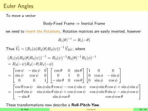
To move a vector
Body-Fixed Frame ⇒ Inertial Frame
we need to Invert the Rotations. Rotation matrices are easily inverted, however
Ri(θ)−1 = Ri(−θ)
Thus ~VI = (R1(φ)R2(θ)R3(ψ))−1 ~VBF , where
(R1(φ)R2(θ)R3(ψ))−1
= R3(ψ)−1R2(θ)
−1R1(φ)−1
= R3(−ψ)R2(−θ)R1(−φ)
=
cosψ − sinψ 0sinψ cosψ 00 0 1
cos θ 0 sin θ0 1 0
− sin θ 0 cos θ
1 0 00 cosφ − sinφ0 sinφ cosφ
=
cos θ cosψ sinφ sin θ cosψ − cosψ sinψ cosφ sin θ cosψ + sinφ sinψcos θ sinψ sinφ sin θ sinψ + cosφ cosψ cosφ sin θ sinψ − sinφ cosψ− sin θ sinφ cos θ cosφ cos θ
These transformations now describe a Roll-Pitch-Yaw.M. Peet Lecture 9: 19 / 24
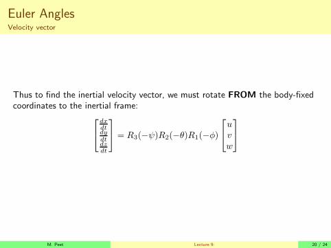
Euler AnglesVelocity vector
Thus to find the inertial velocity vector, we must rotate FROM the body-fixedcoordinates to the inertial frame:
dxdtdydtdzdt
= R3(−ψ)R2(−θ)R1(−φ)
uvw
M. Peet Lecture 9: 20 / 24
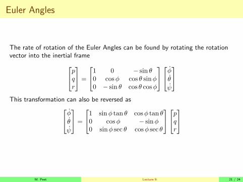
Euler Angles
The rate of rotation of the Euler Angles can be found by rotating the rotationvector into the inertial frame
pqr
=
1 0 − sin θ0 cosφ cos θ sinφ0 − sin θ cos θ cosφ
φ
θ
ψ
This transformation can also be reversed as
φ
θ
ψ
=
1 sinφ tan θ cosφ tan θ0 cosφ − sinφ0 sinφ sec θ cosφ sec θ
pqr
M. Peet Lecture 9: 21 / 24

Summary
M. Peet Lecture 9: 22 / 24

Conclusion
In this lecture we have covered
Equations of Motion
• How to differentiate Vectors in Rotating Frames
• Derivation of the Nonlinear 6DOF Equations of Motion
Euler Angles
• Definition of Euler Angles
• Using Rotation Matrices to transform vectors
• Derivatives of the Euler anglesI Relationship to p-q-r in Body-Fixed Frame
M. Peet Lecture 9: 23 / 24
Next Lecture
In the next lecture we will cover
Linearized Equations of Motion
• How to linearize the nonlinear 6DOF EOM
• How to linearize the force and moment contributions
Force and Moment Contributions
• The gravity and thrust contributions
• The full linearized equations of motion including forces and moments
• How to decouple into Longitudinal and Lateral DynamicsI Reminder on how to create a state-space representation.
M. Peet Lecture 9: 24 / 24