Spaceborne Doppler Wind Lidars - Scientific motivation and impact studies for ADM/Aeolus

Spaceborne Laser Technology for Lidar Remote Sensing
Weibiao Chen
Shanghai Institute of Optics and fine Mechanics, Chinese Academy of Sciences
1
Winter College on Optics Light: a bridge between Earth and Space

Outline
Laser requirement for Lidar remote sensing
History of spaceborne laser
Design of spaceborne solid-state laser
Examples of developing spaceborne laser
Laser components in space environment
Conclusion
2

Outline
Laser requirement for Lidar remote sensing
History of spaceborne laser
Design of spaceborne solid-state laser
Examples of developing spaceborne laser
Laser components in space environment
Conclusion
3

Application of Spaceborne laser
4
Space Science and
Metrology
Space measurement
and communication
•Gravitational waves
•Cold atomic clock
•Optical clock
•Atom interferometer
•Time metrology
•Deep space detection
•Laser communication
•Formation flying
•Rendezvous and docking
Earth observation
with Lidar
•Aerosol and dust
•Cloud
•Atmospheric composition
•Atmospheric dynamics
•Earth topography
Application of Space Laser

Application of Spaceborne laser
5
Space laser communication laser link for navigation
Space laser interferometer Formation flying
Space laser ranging

Application of Spaceborne laser
6
Space Science and
Metrology
Space measurement
and communication
•Gravitational waves
•Cold atomic clock
•Optical clock
•Atom interferometer
•Time metrology
•Deep space detection
•Laser communication
•Formation flying
•Rendezvous and docking
Earth observation
with Lidar
•Aerosol and dust
•Cloud
•Atmospheric composition
•Atmospheric dynamics
•Earth topography
Application of Space Laser

Light Detection And Ranging-- Lidar
7

Atmospheric Vertical profile

Classification of Lidar
Lidar Type Principle Values Target
Laser altimeter,
Laser bathymetry
Back reflecting Time Topography, Depth
Doppler Lidar Doppler Frequency
Shift
Wind speed
Different
Absorption Lidar
Atomic, molecular
absorption
Intensity Atmospheric composition
Fluorescence Lidar Fluorescence Wavelength,
Intensity
Atmospheric composition
Raman Lidar Raman scattering Wavelength,
Intensity
Atmospheric composition
, temperature
Mie Lidar Mie Scattering Intensity Aerosol, cloud
Rayleigh Lidar Rayleigh
Scattering
Intensity Temperature, molecule
density
9

10 2011年研究生讨论会
Cross-section of different principle

Spaceborne Lidar for Earth Observation
Spaceboren Lidar is the lidar operated at space platform, such as satellite, space station, space shuttle.
Spaceborne Lidar is used to remote sensing the properties of earth’ s atmosphere, surface, ocean, et.al.
11
Spaceborne Lidar
• Spacrborne lidar needs receive enough return power and enough ratio of signal to noise to retrieve information of earth.
• Cross-section, laser power and receiver’s area is closely relative to Lidar’s return.
12 1. L.Bonino, Lidar concepts for space applications, Thales Alenia Space Italy

Classification of Lidar
Lidar Type Principle Values Target
Laser altimeter,
Laser bathymetry
Back reflecting Time Topography, Depth (very
shallow)
Doppler Lidar Doppler Frequency
Shift
Wind speed
Different
Absorption Lidar
Atomic,
molecular
absorption
Intensity Atmospheric composition
Fluorescence
Lidar ?
Fluorescence Wavelength,
Intensity
Gas composition
Mesosphere
Raman Lidar Raman
scattering
Wavelength,
Intensity
Atmospheric composition,
temperature
Mie Lidar Mie Scattering Intensity Aerosol, cloud
Rayleigh Lidar Rayleigh
Scattering
Intensity Temperature, molecule
density
13

Spaceborne Lidar for Earth Observation
Backscattering Lidar
Different Absorption Lidar (DIAL)
Doppler Lidar Topography Lidar
Dire
ct D
etectio
n
High
Spe
ctrum
R
eso
lutio
n
Dete
ction
Dire
ct D
etectio
n
Hete
rod
yne
Dete
ction
Dire
ct D
etectio
n
Co
he
ren
t D
etectio
n
An
alog
Ph
oto
n
cou
ntin
g
Single Array
14
What’s requirement of space laser for different Lidar?

Backscattering Spaceborne Lidar (direct detection)
Cloud
Aerosol
15
Backscattering Lidar –Aerosol, molecule optical thickness, cloud
top height, and optical thickness
Laser requirement: high energy, 2~3 wavelengths
CALIPSO

Backscattering Spaceborne Lidar
• High spectrum resolution Lidar
16

Laser requirement of space HRSL Lidar
17
RdRRRR
R
RGAK
cPRP
r
rMaMa
0
)()(2 exp)()()(
2)(
20
Rich Ferrare, Chris Hostetler, Ed Browell, John Hair, Spaceborne Aerosol and Ozone Lidars for Air Quality ApplicationsNCAR Community Workshop on Air Quality Remote Sensing from Space, February, 2006
Laser requirement for HSRL: Single frequency with narrow linewidth Frequency stability: ~ 20 MHz High energy: ~ 100 mJ Two wavelengths

Spaceborne Doppler Lidar
18
Doppler Lidar: Wind Direct direction measurement : ALADIN Coherent measurement

Laser requirement of space Doppler Lidar
• Laser for Doppler wind Lidar – Single frequency, narrow linewidth – Frequency stability: ~ 1 MHz – High pulse energy with middle repetition rate – Usually in UV or 2 micrometer
19
Mie detection with Fizeau Filter
Molecule detection with double FP filter

Spaceborne DIAL Lidar
20

Laser requirement of space DIAL Lidar
• Laser for DIAL Lidar: – Exact single wavelength to match absorption
line of molecule – Usually two or multi-wavelengths – Long term wavelength stability – Narrow linewidth, such as CO2 – High spectrum purity – High Energy with middle repetition rate
21
CO2 H2O
O2
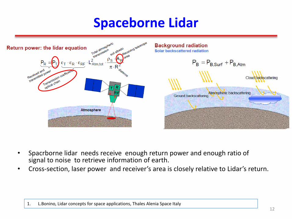
Spaceborne topography Lidar
22
From single beam to multi-beam From analog detection to photon counting

Laser requirement of space topography Lidar
23
Laser requirement for topography Lidar
– Analog detection : – Pulse energy: ~ 70 mJ
– Pulse width: ~7 ns
– Repetition rate: < 100 Hz
– Photon counting: – Narrow pulse width: < 1ns
– High repetition rate: ~10 kHz
– Low pulse energy: 0.1~ 1 mJ

Requirement of laser for Earth Observation Lidar
CO2、CH4 Wind Aerosol、cloud Topography Ocean Mix layer
2051nm 355 nm 1064 nm 532 nm 1645 nm 1572 nm
Frequency
Stability Pulsed High repetition
Rate
Narrow
LineWidth
Single
Frequency
High Repetition rate,
narrow pulse width solid-
state of fiber laser
Single frequency,
frequency stable pulsed
Nd: YAG laser
Frequency stable, narrow
linewidth, pulsed OPO、OPA
Or Frequency stable 2μ solid-
state laser
24
Doppler Lidar DIAL Lidar Laser altimeter HSRL Lidar

Typical Requirement of space laser for Earth Observation
Sensor Application Parameters of laser
Ima
gin
g L
ida
r
/laser a
ltimeter
Earth Wavelength: 1 μm, Pulse energy:> 150 mJ, PRF:1~40 Hz
Planetary Wavelength: 1 μm, Pulse energy:> 50 mJ, PRF: 1~20 Hz
Topography Wavelength: 1 μm,Pulse energy:> 100 μJ
PRF: 5~10 kHz,Beam number:1000
Atm
osp
heric L
idar
Win
d
Direct
Detection
Wavelength: 0.35 μm,Single frequency, narrow linewidth,
Pulse energy: >150 mJ,PRF: >100 Hz
Coherent
Detection
Wavelength: 2.05 μm, Single frequency, narrow linewidth,
Pulse energy: >1 J, PRF>50 Hz
Backscattering
(Cloud, aerosol)
Wavelength: 0.35 μm,0.5 μm,1.0 μm,Single frequency,
Pulse energy: >100 mJ, PRF: 20~50 Hz
DIAL CO2 Wavelength:1.57 μm /2.05 μm, Frequency stability:<0.3
MHz, Pulse energy: >50 mJ, PRF: > 50 Hz
CH4 Wavelength: 1.65 μm , Frequency stability: < 0.9 MHz
Pulse energy: >20 mJ, PRF: > 50 Hz
25
Outline
Laser requirement for Lidar remote sensing
History of spaceborne laser
Design of spaceborne solid-state laser
Examples of developing spaceborne laser
Laser components in space environment
Conclusion
26

History of spaceborne lidar
Spaceborne lidar has a history more than 40 years.
Up to now, almost all spaceborne lidar used solid-state laser.
27

History of spaceborne laser
Apollo 15 Laser altimeter (USA,1971) Moon explorer
Lamp Pumped Ruby laser • Wavelength : 694.3 nm • Pulse energy : 200 mJ • Pulse width: 10 ns • Pulse repetition rate: 3.75/min.
Clementine laser altimeter (USA, 1994) Moon explorer
Diode pumped Nd:YAG • Wavelength: 1064 nm • Q-switch : LiNbO3 • Pulse energy :171 mJ • Pulse width: 8 ns • PRF: 1-8 Hz
1. Roberson FL, Kaula WM. Apollo 15 laser altimeter [C]. Apollo 15: Preliminary Science Report. 1972:48. 2. Nozette Stewart, Rustan P, Pleasance LP, etc. The Clementine mission to the Moon: Scientific overview
[J]. Science, 1994, 266(5192): 1835-1839. 28

History of spaceborne laser
Diode Pumped Nd:YAG • Q-switch: LiNbO3 • Wavelength: 1064 nm • Pulse energy: 100 mJ • Pulse width: 15 ns • PRF: 1 Hz
CE-1 Laser altimeter (China, 2007) Moon explorer
SELENE Laser altimeter (Japan, 2007) Moon explorer
Diode Pumped Nd:YAG • Q-switch: KD*P • Wavelength: 1064 nm • Pulse energy: 150 mJ • Pulse width: 7ns • PRF: 1 Hz
1. KASE Teiji, ABE Kikuo, HOTTA Tomomi, etc. LALT: Laser Altimeter for luna exploring satellite SELENE: Active and passive sensors for
remote sensing [J]. NEC research & development, 2003, 44(2): 175-180.
2. J. Wang, S. Rong, W. Chen, CE-1 Laser altimeter, Science bulletin of China , 2010, (8): 1063-1070. 29

History of spaceborne laser
LLRI laser Altimeter (India, 2008) Moon explorer
Diode pumped Nd:YAG • Q-switch: Actively, LiNbO3 • Pulse Energy: 10 mJ • Pulse energy : 2 ns • PRF: 10 Hz
Diode pumped Nd:YAG • Q-switch: Passively, Cr:YAG • Pulse energy: 2.7 mJ • PRF: 28 Hz • Five beams
1. Kamalakar JA, Prasad AS Laxmi, Bhaskar KVS, etc. Lunar laser ranging instrument (LLRI): a tool for the study of topography and gravitational
field of the moon [J]. Curr. Sci, 2009, 96(4): 512-516.
2. Smith David E, Zuber Maria T, Jackson Glenn B, etc. The lunar orbiter laser altimeter investigation on the lunar reconnaissance orbiter mission
[J]. Space Science Reviews, 2010, 150(1-4): 209-241.
LOLA laser Altimeter (USA , 2008) Moon explorer
30

History of spaceborne laser
Diode Pumped Nd:YAG • Q-switch: Active, LiNbO3 • Pulse Energy:42mJ • Pulse energy : 8 ns • PRF: 10 Hz
MOLA Mars Laser altimeter (USA, 1996) Mars explorer
Mercury Laser altimeter (USA, 2004) Mercury Explorer
Diode pumped Nd:YAG • Q-switch: Passive, Cr:YAG • Pulse energy: 20 mJ • PRF: 8 Hz
1. Afzal Robert S. Mars observer laser altimeter: laser transmitter [J]. Applied Optics, 1994, 33(15): 3184-3188.
2. Zuber Maria T, Smith David E, Solomon Sean C, etc. Laser altimeter observations from MESSENGER's first Mercury flyby [J]. Science, 2008,
321(5885): 77-79.
31

Lidar for earth observation
LITE is first lidar to observe atmosphere of earth on space shuttle; Milestone It run only 21 days. It was a successful demonstration of lidar for earth remote
sensing. Lamp pumped Nd:YAG at 1064 nm, 532 nm, and 355 nm
32

Lidar for earth observation
Output 1064 nm, 532 nm, 355 nm
Folded cavity with porro prism , actively Q-switched
MOPA Lamp pumped SHG and THG
33

History of spaceborne laser
CALIPSO –backscattering Lidar Diode pumped, EO Q-switched Nd:YAG • Wavelength: 1064 nm & 532 nm • Pulse energy: 110 mJ @ 1064 nm 110 mJ @ 532 nm • PRF: 20 Hz
GLAS- Laser altimter Diode pumped, Passive Q-switch, MOPA Nd:YAG • Wavelength: 1064 nm & 532 nm • Pulse energy: 75 mJ @ 1064 nm 35 mJ @ 532 nm • Pulse width: < 10 ns • PRF: 40 Hz
1. Abshire James B, Ketchum EA, Afzal RS, etc. The geoscience laser altimeter system (GLAS) for the ICEsat mission [C]. Lasers and Electro-Optics,
2000.(CLEO 2000). Conference on. IEEE, 2000:602-603.
2. Winker David M, Hunt William H, Hostetler Chris A. Status and performance of the CALIOP lidar [C]. Remote Sensing. International Society for Optics
and Photonics, 2004:8-15. 34
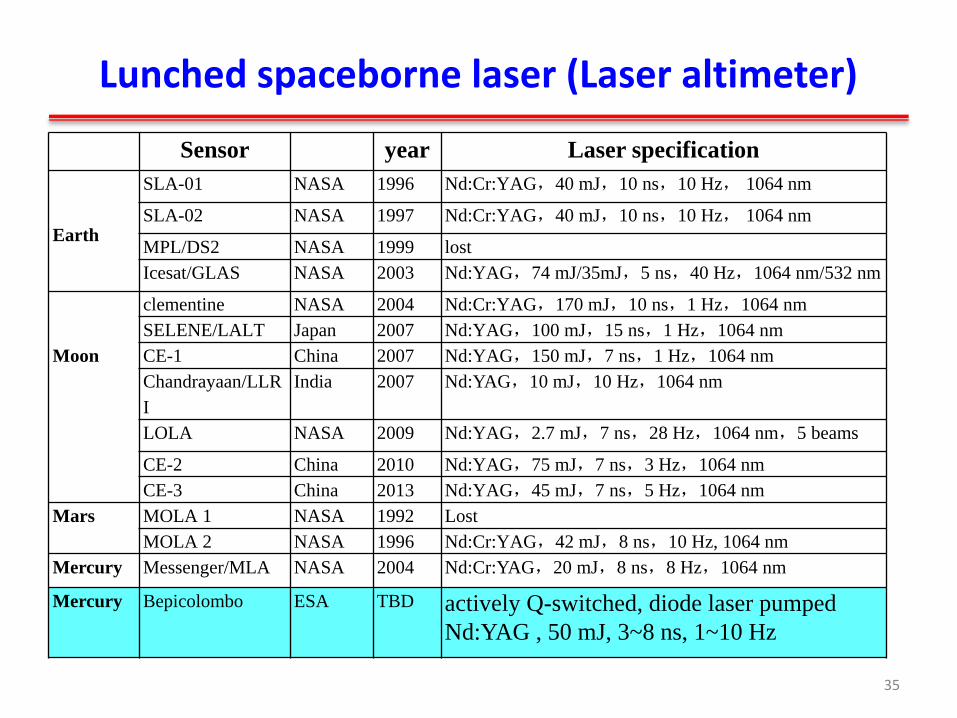
Lunched spaceborne laser (Laser altimeter)
Sensor year Laser specification
Earth
SLA-01 NASA 1996 Nd:Cr:YAG,40 mJ,10 ns,10 Hz, 1064 nm
SLA-02 NASA 1997 Nd:Cr:YAG,40 mJ,10 ns,10 Hz, 1064 nm
MPL/DS2 NASA 1999 lost
Icesat/GLAS NASA 2003 Nd:YAG,74 mJ/35mJ,5 ns,40 Hz,1064 nm/532 nm
Moon
clementine NASA 2004 Nd:Cr:YAG,170 mJ,10 ns,1 Hz,1064 nm
SELENE/LALT Japan 2007 Nd:YAG,100 mJ,15 ns,1 Hz,1064 nm
CE-1 China 2007 Nd:YAG,150 mJ,7 ns,1 Hz,1064 nm
Chandrayaan/LLR
I
India 2007 Nd:YAG,10 mJ,10 Hz,1064 nm
LOLA NASA 2009 Nd:YAG,2.7 mJ,7 ns,28 Hz,1064 nm,5 beams
CE-2 China 2010 Nd:YAG,75 mJ,7 ns,3 Hz,1064 nm
CE-3 China 2013 Nd:YAG,45 mJ,7 ns,5 Hz,1064 nm
Mars MOLA 1 NASA 1992 Lost
MOLA 2 NASA 1996 Nd:Cr:YAG,42 mJ,8 ns,10 Hz, 1064 nm
Mercury Messenger/MLA NASA 2004 Nd:Cr:YAG,20 mJ,8 ns,8 Hz,1064 nm
Mercury
Bepicolombo
ESA TBD actively Q-switched, diode laser pumped
Nd:YAG , 50 mJ, 3~8 ns, 1~10 Hz
35

Lunched spaceborne laser (Lidar)
Earth
LITE NASA 1994 Nd:Cr;YAG 1064 nm/532 nm/355 nm ,Lamp
pumped
BALKAN Russia 1995 Nd:Cr;YAG,1064 nm/532 nm,lamp pumped
GLAS NASA 2003 Nd:YAG,74 mJ/35mJ,5 ns,40 Hz,1064
nm/532 nm
CALIPSO NASA 2006 Nd:YAG,110 mJ@1064 nm & 532 nm,20Hz
ALADIN ESA TBD Single frequency Nd:YAG, 150 mJ @355 nm, 100 Hz
Mars Phoenix NASA 2007 Nd:YAG,30 mJ,15 ns,1 Hz, 1064 nm, 532
nm
36

Lunched spaceborne laser(Others)
Application Sensors year Parameters of laser
Laser
Communication
SILEX/ ESA AlGaAs Diode laser,847 nm/819 nm,100 mw
TerraSAR-X ESA 2007 Nd:YAG+fiber amplifier,1064 nm,1.2
W,SLM
ALphsat and
Sentine 1+2
ESA 2013 Nd:YAG + fiber amplifier,1064 nm,2.5 W,SLM
LLCD NASA 2013 Er:Fiber,0.5 W,1550 nm
RVD Lidar ETS-VII JAPAN 1998 Laser diode
XSS-11 NASA 2005 Cr,Nd:YAG,1064 nm,10 kHz,1 ns,
Gravitational-Wave
LISA、eLISA ESA TBD NPRO Nd:YAG
Cold atomic
clock
PHARAO ESA TBD Cs stabled 852 nm, diode laser
CCAC China 2016 Rb stabled 780 nm, diode laser
CAL NASA TBD Rb, K,780 nm,852 nm,767 nm,Diode laser or Frequency doubled Fiber
laser (1560 nm or 1534 nm) 37

Flash Lamp pumped lasers
More than 30 solid-state lasers were lunched into space for lidar measurement.
38 Robert S. Afzal, Review of Solid-State Lasers for Space Applications, Solid State Lasers XV: Technology and Devices, Proc. of SPIE Vol. 6100, 61001U, (2006)

Performance of CALIPSO’s laser
39
Folded Porro cavity Diode side pumped SLAB KD*P Q-switch KTP frequency doubled Operated in air sealed container
Beam expander
radiator

Performance of CALIPSO’s laser
Floyd Hovis, THE LASER TRANSMITTERS FOR THE NASA/CNES CALIPSO AND NASA ICESAT-2 MISSIONS, IGARSS 2012 40

Performance of MLA’s laser
Linear Porro cavity oscillator +power amplifier
Cr:YAG passively Q switched Side pumped SLAB for oscillator
and amplifier Operated in vacuum
41

Performance of MLA’s laser
Mercury laser altimeter form 2011
Anthony W. Yu1, Xiaoli Sun, Steven X. Li, John F. Cavanaugh, and Gregory A. Neumann, In-Flight Performance of the Mercury Laser Altimeter Laser Transmitter, Solid State Lasers XXIII: Technology and Devices,Proc. of SPIE Vol. 8959,
42

Performance of GLAS’s laser
43
Linear hemi-porro cavity Cr:YAG passively Q-switched Double pass Pre-amplifier +
power amplifier Side pumped SALB Frequency doubled Operated in vacuum
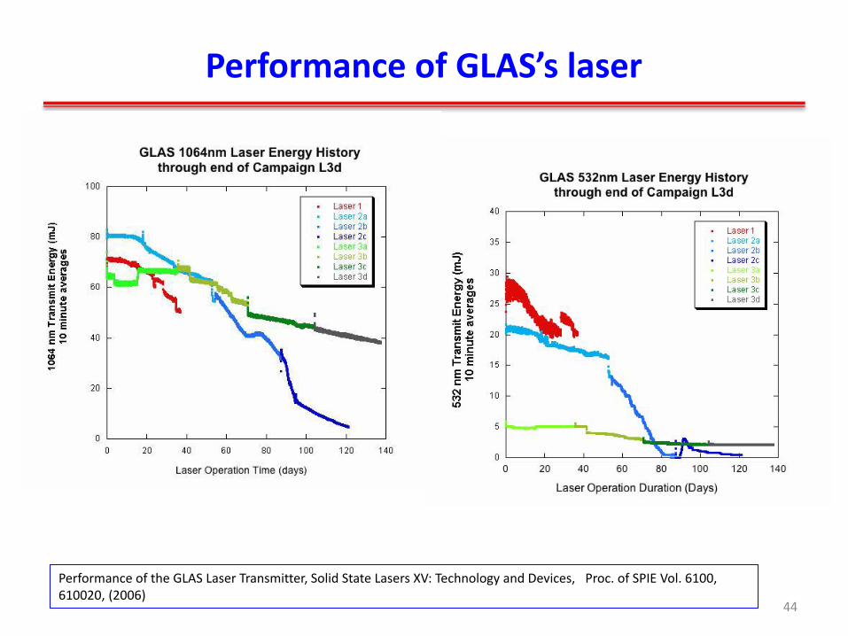
Performance of GLAS’s laser
Performance of the GLAS Laser Transmitter, Solid State Lasers XV: Technology and Devices, Proc. of SPIE Vol. 6100, 610020, (2006)
44

Near Future Mission
ALADIN in ADM (ESA) – It will be the first Doppler Lidar in the world
– An UV ,single frequency pulsed laser (Frequency trebled Nd:YAG)
ATLID in EarthCARE (ESA) – It will be the first high spectrum resolution Lidar
to measure atmospheric molecule and high altitude cloud
– An UV, single frequency pulsed laser (laser (Frequency trebled Nd:YAG)
45

ALADIN’s laser
Injection Seeding, MOPA Folded linear cavity Double pre-amplifier+ power amplifier Sided pumped SLAB Frequency trebled
Operated in vacuum? Or with O2 to avoid optics damage
46
1. UV CHARACTERIZATION OF ENGINEERING QUALIFICATION MODEL OF ALADIN LASER TRANSMITTERINTERNATIONAL CONFERENCE ON SPACE OPTICS 2006
2. Didier Morançais, Frédéric Fabre, Martin Endemann, Alain Culoma, ALADIN Doppler Wind Lidar: Recent advances, Lidar Technologies, Techniques, and Measurements for Atmospheric Remote Sensing III,, Proc. of SPIE Vol. 6750, 675014, (2007)

ATLID’s laser
47 Alberto Cosentino, Alessandro D’Ottavi, Adalberto Sapia, Enrico Suetta, Spaceborne Lasers Development for ALADIN and ATLID Instruments, IGARSS 2012
Similar design with ALADIN with modified cooling system and structure Operated in sealed air pressurized environment

Bright future of spaceborne laser
NASA, ESA and China are developing spaceborne lidar to sound atmospheric aerosol, cloud, composition, wind, etc.
In the next decades, there are several lidars to be launched into space.
Reliability and lifetime of spaceborne laser has been improved greatly during past 40 yrs.
Laser is still a great challenge for spaceborne lidar.
48

Outline
Application of Lidar remote sensing
History of spaceborne Laser
Design of spaceborne solid-state Laser
Examples of developing spaceborne laser
Laser Components in Space Environment
Conclusion
49

Special characteristics of spaceborne laser
Compact, robust;
high efficiency and conductively cooling;
Long lifetime under space environment (vacuum, radiation, Temperature);
High beam point stability after vibration, TVAC testing ,and it is most important for lidar, especially.
50

Typical Lasers for Space Application
Most lunched spaceborne lasers are solid-state lasers. Solid-state laser has merits of electronically droved,
compact. Solid-state laser is divided into:
Diode pumped buck solid-state laser (Rod, Slab) Fiber laser and fiber laser amplifier
thermal lens & thermal stress-induced birefringence
reduced thermo-optical distortions 51

Design items of spaceborne laser
plug Efficiency
Mechanics
&Cooling
Electronics
Weight, power,
volume Component
Risk evaluation
Lifetime
Requirement Input
Scheme Design
Manufacture &
Technics
Environment
Routine test
Up screening
Requirement analysis Scheme design and optics simulation Structure design and mechanical analysis Thermal design and simulation Driver electronics design Reliability design Test and validation
52

Concept of Solid-state laser
Single
Frequency
Seed laser
Seed Laser
Electronics
Power supplier and Diode Driver
System Timing Controller
Q-switcher
driver
Oscillator Power Amplifier Non-linear Crystal
Frequency converter • SHG • THG • OPO
optional
Different Lidar requires different options: ① Oscillator only (CW, QCW, pulsed) ② Oscillator + Amplifier ③ Single frequency ④ Other wavelengths by nonlinear converter.
53

Typical Solid-state Laser -1
Buck Oscillator
Fiber Oscillator
54

Typical Solid-state Laser-2
Fiber Amplifier
Master Oscillator Power Amplifier (MOPA) with single frequency and SHG
Narasimh S. Prasad, Upendr N. Singh, Floyd Hovis, Darrell J. Armstrong,High energy, single-mode, all-solid-state and tunable UV laser transmitter, Laser Radar Technology and Applications XI,Proc. of SPIE Vol. 6214, 62140T, (2006)
55

Design of solid-state laser (1)--Oscillator
1. System Efficiency
2. Output Energy
3. Beam Quality
4. Single Frequency
Optical Resonator
1. Cavity Length 2. Mode Size 3. Cavity Stability 4. Output Coupling
1.Gain Material 2.Pump Volume in Gain Medium 3.Pump Coupling Scheme Heat Removal 4.Intracavity Thermal Lensing 5.Thermal Lensing Compensation
Gain medium
56

Design of solid-state laser (1)--Oscillator
• Modeling & Simulation
Resonator Configuration
Modeling & Software (ie. LASCAD, GLAD)
Thermal
Effect
Ray Tracing
(ie. Zemax)
Thermal Analysis
(ie. ANSYS)
Thermo-Optic Effects
Data Process
(ie. MATLAB)
Laser
Output
Energy
Beam Quality
Single Frequency
Gain Medium Optical Resonator
57

Design of Oscillator--Cavity
Folded or linear cavity with cross Porro prism (LOLA, Clementine、Messenger—MLA )
1. Kushina Mark E, Grote Michael G, Wiswall Charles E, etc. Clementine: Diode-pumped laser qualification [C]. Photonics West'95. International Society for
Optics and Photonics, 1995:137-140.
2. Anthony W Yu, Novo-Gradaca Anne Marie, Shawa George B, etc. The lunar orbiter laser altimeter (LOLA) laser transmitter [C]. Lasers and Applications in Science and Engineering. International Society for Optics and Photonics, 2008:68710D-68710D-4.
58

Design of Oscillator-- Cavity
Compact linear cavity (CE-1, Selene, Bepicolombo)
Porro Prism Q-switcher Polarizer Pump head Output
coupler WP
CE-1 Laser
Bepicolombo
1. Qualification testing of the laser transmitter part for ESA’s BepiColombo Laser Altimeter (BELA), Lidar Remote Sensing for Environmental Monitoring XII, Proc. of SPIE Vol. 8159, 815906
59

Design of Oscillator- Cavity
Ring cavity with injection seeding.
It is designed for single frequency laser typically, such as Doppler lidar, high spectral resolution Lidar
Narasimh S. Prasad, Upendr N. Singh, Floyd Hovis, Darrell J. Armstrong,High energy, single-mode, all-solid-state and tunable UV laser transmitter, Laser Radar Technology and Applications XI,Proc. of SPIE Vol. 6214, 62140T, (2006) 60

Design of Oscillator-- Q-switch
a. During pumping duration, Q of cavity is low;
b. Just after pumping, the population of inversion is maximum, then Q-switcher is opened;
c. Q of cavity is increased immediately ;
d. The energy is released in a short time.
e. Huge laser pulse is generated with a pulse width around several ten ps to several hundred ns.
61
Space laser is usually operated in pulse mode, therefore it has a Q-switcher to get huge pulse.
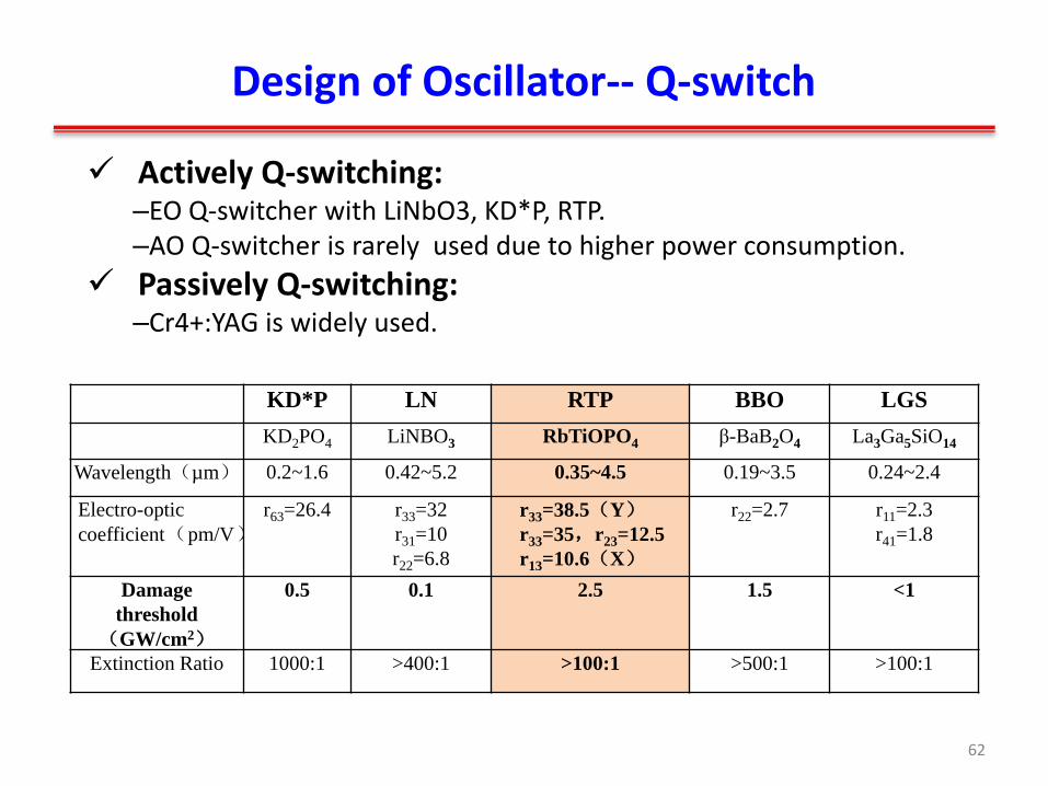
Design of Oscillator-- Q-switch
Actively Q-switching: –EO Q-switcher with LiNbO3, KD*P, RTP. –AO Q-switcher is rarely used due to higher power consumption.
Passively Q-switching: –Cr4+:YAG is widely used.
KD*P LN RTP BBO LGS
KD2PO4 LiNBO3 RbTiOPO4 β-BaB2O4 La3Ga5SiO14
Wavelength(µm) 0.2~1.6 0.42~5.2 0.35~4.5 0.19~3.5 0.24~2.4
Electro-optic
coefficient(pm/V)r63=26.4 r33=32
r31=10
r22=6.8
r33=38.5(Y)
r33=35,r23=12.5
r13=10.6(X)
r22=2.7 r11=2.3
r41=1.8
Damage
threshold
(GW/cm2)
0.5 0.1 2.5 1.5 <1
Extinction Ratio 1000:1 >400:1 >100:1 >500:1 >100:1
62

Design of Oscillator-- Q-switch
Actively Q-Switch rate equation ,
P : peak pump power Tp: Pump duration α: absorbed fraction, X: pump coupling efficiency Χ: quantum efficiency hυ: photon energy V : volume of laser crystal
Robert S. Afzal, Mars Observer Laser Altimeter: laser transmitter, APPLIED OPTICS / Vol. 33, No. 15 / 20 May 1994 63

Design of Oscillator-- Q-switch
Passively Q-Switch rate equation
)1(1
1
)1(1
1
,10
opt
opt
opt
e
e
GT
opt
opt
optOpt
1ln212,
0
0
opt
optoptG
LGR opt
2)ln(
2
)ln(0
0 optoptgain
sat
optopt
opt AGFGAh
E
Degnan John J. Optimization of passively Q-switched lasers [J]. Quantum Electronics, IEEE Journal of, 1995, 31(11): 1890-1901. 64

Design of Solid-state Amplifier
Efficiency, Energy Storage & Exaction Efficiency
• Thermo-optic Effects
• Optical-damage Threshold
• SE &ASE
Gain Medium
Pump Design
Cooling Systems
Compensation Systems
Consideration Design Contents
Optimum Design: High Efficiency & Beam Quality
65

Design Model of Amplifier
66

Characters of the amplifiers
Eout
A
Ein
efff
-the input signal energy, -the active cross sectional area of the zig-zag slab,
- the complementary angle,
- the effective overlap factor
The Predicated Output Energy
67
storedE - the stored energy
cos 2out satE E A f f
ln 1 exp 1 exp
cos 2 cos
in stored
sat sat
E E
AE f f AE
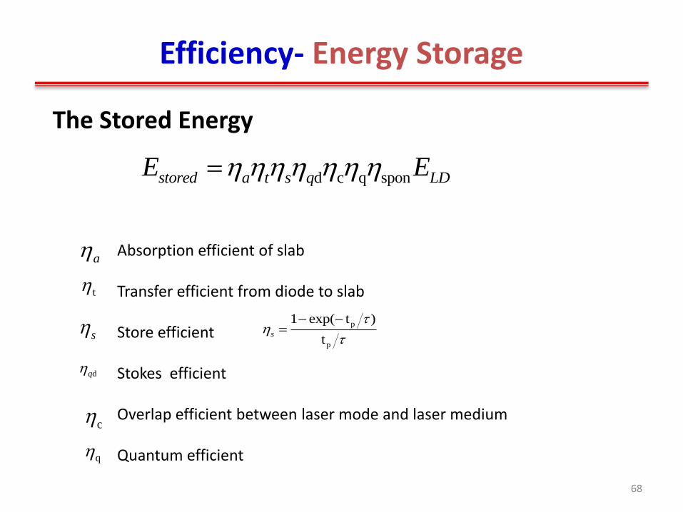
Efficiency- Energy Storage
68
d c q sponstored a t s q LDE E
The Stored Energy
Absorption efficient of slab Transfer efficient from diode to slab Store efficient Stokes efficient Overlap efficient between laser mode and laser medium Quantum efficient
t
a
sp
p
1 exp( t )
ts
dq
c
q

Efficiency- Energy Extraction
The extraction efficiency:
The output fluence of a solid-state power amplifier :
• - the spatial mode-overlap efficiency,
• - the output fluence,
• - the input signal fluence,
• - the signal optical path length.
/ln{1 [ 1] }o effin sat
g lF F
out overlap satF F e e
out in
sat o eff
F F
overlap F g l
effl
inF
overlap
outF
Limit of Energy Exaction: input signal fluence,
spatial mode-overlap efficiency, pump energy & configuration optical surface damage
69

Efficiency- Energy Extraction
• Diode pumped Nd:YAG ZigZag SLAB amplifier
absorbo o quantum store extractiontransfer stokes overlap
Optical Efficiency o o
o o LD
Optical Transfer Absorption
Upper State
Stokes
Storage
Extraction
Beam Overlap
14.5% 90% 90% 91% 76% 73% 50% 70%
70

Design of different wavelength output
71
ε0: the permittivity of free space χ: the linear susceptibility representing the linear response of the material.
Second order nonlinearity χ(2)
Second harmonic generation
Sum- and Difference-Frequency Generation
Parametric amplification
Third order nonlinearity χ(2)
Third harmonic generation
Kerr effect
Stimulated Raman Scattering

Design of Harmonic Generation
• Important factors: – Type I or Type II
selection – Crystal selection – Damage threshold – Beam divergence
72 deff is the effective nonlinear coefficient
Type I
Type II

Design of Harmonic Generation
73
Ciapponi Alessandra, Riede Wolfgang, Tzeremes Georgios, etc. Non-linear optical frequency conversion crystals for space applications ,Proc. SPIE 7912, Solid State Lasers XX: Technology and Devices, 791205

Design of Parametric Oscillators
74
0p s ik k k k
0p s i
p s i
n n n
1 1 1,
p s i
KTA
LN/PPLN
KTP/PPKTP
PPLT

Other design of space laser
Mechanics design: – Light weight and good stability;
– lower stress deformation;
– Pressured structure;
– Good thermal conductivity
Thermal controlling – Survive in a relative wide temperature range
– Operate with stable output in a certain temperature range
75

Examples of mechanics and thermal design
76

Summary
Type of cavity, Q-switcher, amplifier and new wavelength generation must be deigned in detail.
The performance of space laser must be estimated by numerical simulation;
Mechanics and thermal controlling is also very important to maunfacture space laser.
Walter Koechner, Solid-state laser engineering
77

Outline
Laser requirement for Lidar Remote Sensing
History and Example of Spaceborne Laser
Design of Spaceborne Solid-state Laser
Examples of developing spaceborne laser
Laser Components in Space Environment
Conclusion
78

EXAMPLES
1. Solid-state laser at 1 μm
a) Lasers for Chinese moon explorer, soft-landing: laser altimeter
b) Single frequency, pulsed oscillator and power amplifier for lidar to remote sensing atmosphere: Doppler, DIAL, HSRL Lidar
c) Nonlinear output: DIAL Lidar
2. Solid-state at 2 μm
79

Spaceborne lasers under developing in SIOM
High energy laser @ UV, Green, IR
Low power laser @ 1μm, 1.5μm
Low PRF Low , Mid-energy
High PRF Low energy
High PRF or CW
Laser range finder
Laser imaging lidar
Laser communication
EO or passive Q-switched
Pulsed MOPA Fiber laser
Single mode Fiber laser
Earth Observation Lidar
Multi -wavelength High Energy
Single frequency SLAB MOPA
Nonlinear frequency
80

Example 1: laser Sensors for Chinese moon explorer
Laser altimeter: to measure the real time altitude during landing Laser imaging lidar: to scanning landing spot to confirm flat surface Doppler Lidar: to measure landing velocity
81

Configurations Crystal: Cr, Nd:YAG
Cavity: Linear, porro & plano mirror
Pump head: Φ4 ×45 mm with diode
side pumping Q-switch: actively, LiNbO3
Solid-state Laser for CE-3 Altimeter
Laser oscillator
Power Supply &Diode
driver
Q-switch driver
Temperature Controler
Beam expander
Internal remote
measurement
Start detector
Energy Monitor
Satellite command bus
Porro Prism Q-
switcher Polarizer Pump head
Output
coupler WP
82
Specification Wavelength: 1064.36 nm Energy : 45mJ Energy stability: 0.2mJ Pulse width: 4.8ns@45mJ 5.5ns@15mJ Repetition rate: 2 Hz Beam divergence: 0.9mrad Point stability: X, y :3.1μrad Weight 1.3kg

Solid-state Laser for CE-3 Altimeter
83
Nd: YAG Diode laser

Principle of Imaging Lidar
• Two axis scanning with 16 beam simultaneously
84

Requirements of Laser for image lidar
Wavelength: 1064nm±2nm;
Rise time 10~90%): <4ns;
Repetition rate: 50 kHz;
Pulse energy: ≥80μJ@50 kHz;
Energy stability: ±5%;
Beam divergence: < 1mrad;
Point stability : < 50μrad;
Dimension : 228mm x 60mm x 215mm
Weight: < 2.6kg
Power : Average: <20W
Passive Q-switched solid-state laser
AO Q-switched solid-state laser
Pulsed fiber laser amplifier
What kind of laser
will be selected ?
Candidate
85

Selection of laser type
Fiber coupled LD Image optics Composited
Nd:YAG+Cr4+:YAG
OC
1064nmHR 808nmAR
Case 1: Passive Q-switched Nd:YAG Case 2: AO Q-switched Nd:YVO4
Case 3: Modulated Laser diode with fiber amplifier
86

Test Results of different lasers
Passive Q-switch laser Nd:YAG Laser High energy Low PRF less than 20 kHz,
Low efficiency
AO Q-switch Nd:YVO4 High PRF Middle efficiency ,Low peak
power and wider pulse width
Fiber laser amplifier High PRF, high efficiency Middle energy but enough Very robust and compact.
87
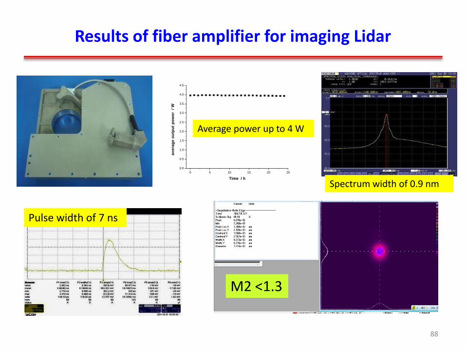
Results of fiber amplifier for imaging Lidar
0 5 10 15 20 25
0.0
0.5
1.0
1.5
2.0
2.5
3.0
3.5
4.0
4.5
av
era
ge
ou
tpu
t p
ow
er
/ W
Time / h
Average power up to 4 W
Spectrum width of 0.9 nm
M2 <1.3
Pulse width of 7 ns
88

Single frequency laser for Doppler Lidar
Seeder LD
SplliterDWDM
Polarized single mode Er fiber
Filter
Polarized double clad single mode Er,Yb Fiber
Local laser Energy monitor
Isolator
Isolated
spliiter
DWDM
MO switcher
Single mode 976 nm LD
(2+1)X1 combiner
Multi-mode 915 nm LD
Multi-mode 915 nm LD
79700000 79800000 79900000 80000000 80100000 80200000 80300000
10-16
10-15
10-14
10-13
10-12
10-11
10-10
10-9
Power
###
Data: FFT1_Power
Model: Lorentz
Equation: y = y0 + (2*A/PI)*(w/(4*(x-xc)^2 + w^2))
Weighting:
y No weighting
Chi^2/DoF = 2.5898E-23
R^2 = 0.72594
y0 -3.6272E-13 ±2.2686E-13
xc 79999182.90024 ±161.43279
w 8997.57441 ±469.03152
A 1.0413E-6 ±3.9418E-8
Frequency (Hz)
Po
we
r
-600000-500000-400000-300000-200000-100000
0
79700000 79800000 79900000 80000000 80100000 80200000 80300000
Frequency (Hz)
An
gle
(de
g)
Linewidth < 9 kHz
Wavelength 1550nm±1nm
Linewidth of seeder ≤30kHz
RIN of seeder (30K~1MHz)
≤2×10-13/Hz
Local laser power 100~120μW
Output power ≥2W
Output fiber 3 local lasers 3 transmitters
Weight ≤1.2kg
89
Example 2: Single frequency, pulsed high energy solid-state laser for Atmospheric Lidar
Laser for Lidar to remote sensing aerosol, wind or CO2.
High energy, single frequency, narrow linewidth, middle repetition rate
Configuration:
– Injection Seeding, EO Q-switched oscillator
– Multi-slab power amplifier
Design and results are demonstrated.
90

Example 2: Single frequency, pulsed high energy solid-state laser
91
Single frequency Oscillator +multi-stage amplifier

Example 2: Single frequency operation
• How to get pulsed single frequency output for solid-state laser? – Mode selection in cavity with FP etalon, prism, grating,
and other narrow line spectrum filter; – Enhance capability of mode competition, and Pre-
lasing; – Injection seeding to pusled cavity – CW single frequency +pused modulated+ amplifier
92

Example 2: Single frequency operation
93
Injection seeder
c/2L
vi vc v
Injection seeding method
v v
Frequency selection
Pre-lasing
Mode selection Pre-lasing

Example 2: Single frequency operation
• Requirement of seeder: – Single frequency, narrow linewidth (<10 kHz),low
intensity noise, stable, compact;
• Candidate: – A NPRO (non--planar ring cavity) Nd:YAG laser
– A short cavity DFB Fiber laser
– External cavity diode laser
• It is also applied in laser interferometer for gravitational-wave missions.
94

Example 2: Single frequency operation
95

Example 2: Single frequency operation
96
Small size NPRO Nd:YAG for large tunable frequency Frequency lock diode to pump NPRO to reduce intensity noise

Example 2: Single frequency operation
97
M2=1.1

Injection Seeding Design
Seeder
Slave laser
Electronics
V0
t t
Adjustable DC offset Fixed
ramp voltage
Ramp-fire & Feedback controlling of the DC voltage
M1 M2
PZT1 PZT2
t0
Un(t)
U0(t)
V0 t
Isolator
Modifized Ramp and Fire Technique
Example 2: Single frequency operation
98

PD
Seeder
Isolator
HW & QW
HR
QS
P
Output
PZT
Wedges
QW
Nd:YAG filter filter
Example 2: Injection seeding End pumped Oscillator
M1 and M2: mirrors
QW: quarter-wave plate
HW: half-wave plate
PZT: piezo actuator
P: polarizer.
Injection Seeding, EO Q-switch, folded cavity, end –pumping Nd:YAG laser
99

• Nd:YAG slab Dimension: 4x4x20-mm Dopant Concentration: 0.7at.% Pump Configuration: End-pumped by Fiber coupled LD array
LDA: Peak power of 300W, D.C. of 2%
Output
Nd:YAG filter filter
Example 2: End pumped Rod Oscillator
100

Results of Resonator calculation--LASCAD
L1
R1 R2
L2 L3
f2 f1 fc
L4
f1=-45mm,
f2=70mm,
fc =130mm,
L1=220mm,
L2=12.5mm
L3=50mm,
L4=50mm
Example 2: End pumped Rod Oscillator
101

Experiment’s Results of oscillator
Repetition 100 Hz
Pulse energy 10 mJ
Pulse duration 13 ns
Longitudinal mode Unique (SLM)
Beam quality (M2) 1.2
Example 2: End pumped Rod Oscillator
102
0 500 1000 1500 2000 2500 3000110
120
130
140
150
Cente
r fr
equ
ency (
MH
z)
Number of pulses
rms= 0.493 MHz

Example 2: Laser Amplifier Configuration
Preamplifier1
Preamplifier2
Power amplifier1
Power amplifier2
Isolator
Expansion scope
Laser output
Input
signal
103

Example 2: The Slabs Dimensions & Parameters
Brief discription Preamplifier1&2 Power-Amplifier1 Power-Amplifier2
Slab length, mm 119.35 119.43 120
Slab width, mm 5 8 10
Slab thickness, mm 5 6 8
Apex angle on both ends, deg 28.78 50 40
Nd+3 doping concentration,% 1.1 1 0.9
Signal input pulse energy, mJ 10 & 60 180 500
Gaussian beam waist size, mm 3 6 8
Stored energy, J 1 1.9 1.6
104

Example 2: Bounce Pump for High Efficiency
Preamplifier 1&2
Power-amplifier1
Power-amplifier2
105

Example 2: Thermal Effect Analysis
Temperature Distribution
Temperature Induced Bending
Temperature Induced Stress
To calculate thermal lens, wave front distortion, depolarization
106

Depolarization results
-1.5 -1 -0.5 0 0.5 1 1.52.96
2.98
3
3.02
3.04
3.06
3.08
3.1
3.12
3.14
Slab Width/mm
Th
erm
al In
du
ce
d D
ep
ola
riza
tio
n L
oss/%
Thermal Induced Depolarization Loss in zigzag plane when z=0
-2.5 -2 -1.5 -1 -0.5 0 0.5 1 1.5 2 2.52
4
6
8
10
12
14
16
Slab Height/mm
Th
erm
al In
du
ce
d D
ep
ola
riza
tio
n L
oss/% Thermal Induced Depolarization Loss in none zigzag plane
Depolarization in the Zigzag Direction Depolarization Perpendicular Zigzag Direction
Example 2: Thermal Effect Analysis
107

Example 2: Comparison of experiment and simulation of thermal lens
100Hz thermal lens
Experiment results
Modeling Results
Index Gradient
induced lens (m)
Bending
Induced lens (m)
Total lens
(m)
50A Zigzag direction
7.4
7
-
7
Perpendicular zigzag direction
3
7
5
2.9
100A
Zigzag direction
*
*
*
*
Perpendicular zigzag direction
1.5
2.2
3.1
1.3
108

Example 2: Compensation of thermal lens
Laser
Beam
(mm)
Preamplifier 1 Preamplifier 2
Power amplifier 1 Power amplifier 2
A B C A B C A B C A B C
3.3 3.4 2.8 3.02 3.87 3.87 6.47 6.73 5.2 7.51 7.54 6
Gauss beam
(mm)
3.2 3.2 2.56 2.7 3.2 3.16 5.1 5.3 4 5.8 5.78 4.6
Ideal beam
3mm 3 mm 6 mm 8 mm
109

Example 2: Predication of output energy
Preamplifier1 Preamplifier2
Power Amplifier1 Power Amplifier2
110

Example 2: Results of amplifier
111
200 400 600 800 1000 1200 1400500
550
600
650
700
750
800
850
pump energy,mJ
ou
tpu
t e
ne
rgy,m
J
Model with Es=0.66J/cm2Model with Es=0.21J/cm2Experiment
200 400 600 800 1000 1200 1400 1600200
250
300
350
400
450
500
550
600
pump energy,mJ
ou
tpu
t e
ne
rgy,m
J
Model with Es=0.66J/cm2Model with Es=0.21J/cm2Experiment
0 100 200 300 400 500 600 700 800 900 10000
20
40
60
80
100
120
pump energy,mJ
ou
tpu
t e
ne
rgy,m
J
Model with Es=0.66J/cm2Model with Es=0.21J/cm2Experiment
0 200 400 600 800 1000 1200 1400 16000
50
100
150
200
250
pump energy,mJ
ou
tpu
t e
ne
rgy,m
J
Laser output from pre-amp1 and pre-amp2
Model with Es=0.66J/cm2Model with Es=0.21J/cm2Experiment
Pre-amplifier1 Pre-amplifier2
Main -amplifier1 Main –amplifier2

Challenges of space laser technology
CO2 lidar needs long term frequency stability and high spectrum purity.
High energy UV laser in space is still a challenge due to optics damage.
New spaceborne Lidar pushes new space laser technology: – Such as multi beam high spectrum resolution Lidar: high
repetition rate, planar waveguide solid-state laser is proposed.
– Lidar or laser range finder with fs laser is a new technology, spaceborne fs laser is frontier .
– O2, H2O, Lidar: Special wavelength without mature laser crystal.
112

Outline
Laser requirement for Lidar remote sensing
History and example of spaceborne Laser
Design of spaceborne solid-state Laser
Examples of developing spaceborne laser
Laser components in space environment
Conclusion
113

Components of Solid-state Laser
Many photonics and optics are assembled in solid-state lasers Any components are related with the failure of laser, and must be
qualified for space environment.
Qualification of Fiber Lasers and Fiber Optic Components for Space Applications, S. Hendow, S. Falvey, B. Nelson, L. Thienel, Maj. T. Drape, SPIE LASE 2006, 6102-59.
114

Qualification of laser’s components
1. Sami Hendow, Suzzanne Falvey, and Burke Nelson, Overview of Qualification Protocol of Fiber Lasers for Space Applications, Solid State Lasers XV: Technology and Devices, Proc. of SPIE Vol. 6100, 61001Y, (2006) 115

Qualification of laser’s components
Howard, Jim, “Space Radiation Environments and Effects”, Presentation, Jackson & Tull, March 2005. 116
Radiation condition

Main laser medium
Nd:YAG Nd:YVO4 Nd:YAP Nd:YLF Nd:GdVO4 Nd:YGG Nd:GSGG Nd:LuAG Yb:YAG
Wavelength
/nm
1064 914.4
1064.3
1342
930
1079
1341
1053(σ)
1047(π)
912.2
1063.1
1340.6
1062 1062 1064 1030
Index
(λ=1.06μm)
1.82 no=1.96
ne=2.18
1.94 no=1.448
ne=1.470
no=1.97
ne=2.19
1.892 1.94 1.83 1.82
Cross
section/10-19cm2
σ946 = 0.37
σ1064 =2.8
σ914=0.48
σ1064=15.6
σ1342=2.8
σ930=0.41
σ1079=4.6
σ1341=2.2
1.2(σ)
1.8(π)
σ912=0.6.6
σ1063=7.6
σ1340=1.8
σ935=0.15
σ938=0.143
σ1062=1.14
1.0 2.89 0.21
Lifetime /μs 230 100 170 480 90 254 289 277 951
Pumping
wavelength /nm
807.5 808.5 803 792(//C)
796(⊥c)
808.5 806 809 809 942
CTC/[W/(m·K)] 14 5.23(//C)
5.1(⊥c)
11 6.3 11.7(沿<110>) 9 6 9.6 7
CTE
/10-6 K-1
7.7-8.2 a:2.2
c:8.4
a:4.2
b:11.7
c:5.1
a:13
c:8
a:1.5
c:7.3
- 7.4 6.13 7.7-8.2
dn/dT(10-6 K-1)
(λ=1. 06μm)
7.3 2.7 a:9.75±0.07
c:14.53±0.07
-2.0 (σ)
-4.3 (π)
4.7 17.6±0.8 10.5 8.3 7.3
117
CTC: coefficient of thermal conductivity CTE: coefficient of thermal expansion

Main laser medium
Laser Fiber: Yb Doped Fiber Er Doped Fiber Yb,Er: Doppler fiber Tm Doped Fiber Ho Doped Fiber
118

Radiation performance of laser crystals
119
1. Acharekar MA, Kaplan MM, McCarthy DP. Radiation hardness of nd: Yag and nd: Cr: Gsgg laser rods. in Laser induced damage in optical
materials. 1986. 1988.
2. Rose TS, Hopkins MS, Fields RA. Characterization and control of gamma and proton radiation effects on the performance of nd: Yag and nd: Ylf
lasers [J]. Quantum Electronics, IEEE Journal of, 1995, 31(9): 1593-1602.
3. Ogawa Takayo, Kawasaki Yoshiya, Takizawa Yoshiyuki, etc. Radiation resistance of nd-doped laser crystals for space application [J]. Japanese
Journal of Applied Physics, 2009, 48(8R): 088001

Radiation performance of laser crystals
Most laser crystals have good radiation performance;
Absorption spectrum in UV and visible is changed larger than that in near infrade after radiation
Some co-doped crystal can improve radiation hardness, such as Cr,Nd:YAG.
Diode pumping, and Q-switch operation is better to improve radiation performance than lamp pumping and CW operation.
120

Radiation performance of Doped fibers
0 2 4 6 8 10
0
50
100
150
200
250
300
350
400
450
Po
we
r(m
W)
kard(Si)
10 krads
0 2 4 6 8 10
135
140
145
150
155
160
165
Po
we
r (m
W)
Time (h)
20 krads
Yb fiber Er fiber
121
stop
stop
Girard Sylvain, Vivona Marilena, Laurent Arnaud, etc. Radiation hardening techniques for er/yb doped optical fibers and amplifiers for space application [J]. Optics Express, 2012, 20(8): 8457-8465.

Radiation performance of Doped fibers
122
Fiber Name NB Al LB NP Al NP Si NP Si+
Erbium absorption (dB/m@ 1530 nm) 4.7 12.3 23 2 3.2
Aluminum (wt%) <1 6-8 4-6 0 0
Pump power (dBm) 23 23 21 23 21
Optimal Length (m) 25 6 2.5 45 22
Output signal (dBm) 17 18 16 17 15
RIA at 1550 nm (dB/m/Gy) 5.5e-4 7e-3 5e-3 2.2e-4 2.8e-4
RIA at 980 nm (dB/m/Gy) 1.2e-3 2e-2 3e-2 3e-4 3e-4
Radiation induced absorption (RIA) of Er doped fiber with different Al
Ott Melanie. Radiation effects expected for fiber laser/amplifier rare earth doped optical fiber [J]. NASA GSFC, Parts, Packaging and Assembly Technologies Office Survey Report, 2004.

Radiation performance of Doped fibers
All doped fiber has relative larger RIA than laser crystal;
Yb Doped and Er: Doped has similar performance under radiation;
Fiber without Al has better performance than that with Al;
Ce co-doped fiber can harden radiation ;
H2 treatment can improve radiation’ performance
123

Radiation effect of nonlinear crystals
1. Roth Ulrich, Tröbs Michael, Graf Thomas, etc. Proton and gamma radiation tests on nonlinear crystals [J]. Applied Optics, 2002, 41(3): 464-469. 2. Ciapponi Alessandra, Riede Wolfgang, Tzeremes Georgios, etc. Non-linear optical frequency conversion crystals for space applications ,Proc.
SPIE 7912, Solid State Lasers XX: Technology and Devices, 791205. 124

Radiation effect of nonlinear crystals
100 krad 10.8 MeV
LiNbO3:Y (0.46 wt%) LiNbO3:Mg (0.27 wt %) LiNbO3:Gd (0.004 wt %)
125

Laser diode in space environment
Laser diode is the most important module for all solid-state laser.
• Lifetime in vacuum;
• Performance after ϒ and proton radiation
126

Example of laser diode used in vacuum
Satellite Sensor Number/wavelength/type Parameters status
MGS (1996-
2001)
MOLA 44/808 nm/array vacuum
150 μs ,10 Hz,60 A
Success
ICESat
(2003~2010)
GLAS 54/808 nm/array vacuum
200 μs,40 Hz,100 A
Lifetime
MESSAGER
(2006-present)
MLA 10/808 nm/array vacuum
160 μs ,8 Hz,100 A
Success
LRO (2008-
presnt)
LOLA 2/808 nm/array vacuum
200 μs ,28 Hz,90 A
Success
CALIPSO(2006-
present)
CALIOP 192/808 nm/array Pressure sealed
150 μs ,20 Hz,60 A
Success
127
No efficient proof to show that laser diode has low lifetime in vacuum While, laser diode occurs problem in vacuum incidentally.
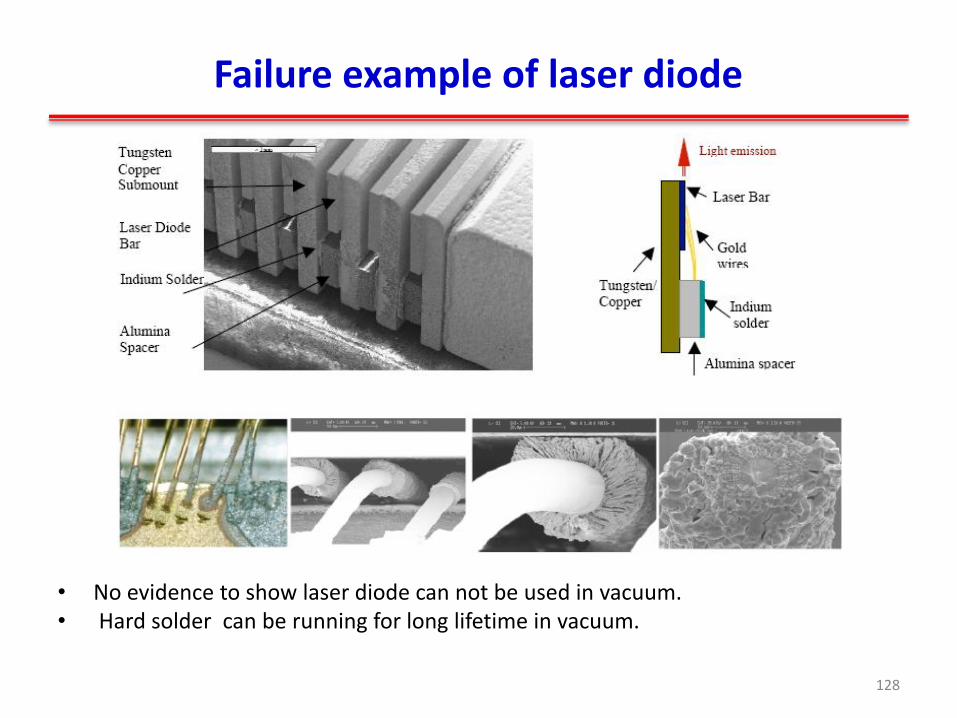
Failure example of laser diode
• No evidence to show laser diode can not be used in vacuum. • Hard solder can be running for long lifetime in vacuum.
128

Lifetime test in vacuum
Lifetime test in vacuum
Lifetime test in vacuum for Indium and gold solder
129
Air 1E-5 Torr

Radiation performance of laser diode
High power Laser diode aray has very good performance under radiation.
Lower power such as DFB, DRB has a little effect of wavelength stability
130
1. Krishnan Kamala S, Smith W David, Hatch Joel M. Laser diode response to gamma and proton radiation [C]. Optical Science, Engineering and Instrumentation'97. International Society for Optics and Photonics, 1997:22-33.
2. Wright Malcolm W, Franzen Don, Hemmati Hamid, etc. Qualification and reliability testing of a commercial high-power fiber-coupled semiconductor laser for space applications [J]. Optical Engineering, 2005, 44(5): 054204-054204-8.

Other components of laser
• Isolator, combiner, modulator, fiber grating are also key components in space laser, especially for space fiber laser.
131 Falvey Suzzanne, Buelow Marisol, Nelson Burke, etc. Fiber laser component testing for space qualification protocol development [C]. The Advanced Maui Optical and Space Surveillance Technologies Conference. 2006:30.

Reliability of optics for spaceborne laser
Self-focus of solid-state laser (large scale, small scale) is a big problem to affect reliability of space laser.
Optical design to avoid optics damage: – Small Scale Self Focusing – Large Scale Self Focusing – Longitudinal Mode Beating – Small Scale Thermal Lensing
Avoiding self-focus is very important for space laser with following methods: • Operated under single frequency • Non strong modulation on laser pulse • No diffraction in laser cavity • Reduce laser power density on optics
132

Reliability of optics for spaceborne laser
CID( Contamination Induced Damage) is another big problem of space laser.
Contamination controlling is very important for developing space laser in every steps.
133
Damage in vacuum with contamination
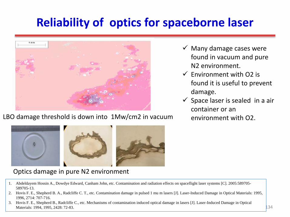
Reliability of optics for spaceborne laser
134
LBO damage threshold is down into 1Mw/cm2 in vacuum
Optics damage in pure N2 environment
1. Abdeldayem Hossin A., Dowdye Edward, Canham John, etc. Contamination and radiation effects on spaceflight laser systems [C]. 2005:589705-
589705-13.
2. Hovis F. E., Shepherd B. A., Radcliffe C. T., etc. Contamination damage in pulsed 1 mu m lasers [J]. Laser-Induced Damage in Optical Materials: 1995,
1996, 2714: 707-716.
3. Hovis F. E., Shepherd B., Radcliffe C., etc. Mechanisms of contamination induced optical damage in lasers [J]. Laser-Induced Damage in Optical
Materials: 1994, 1995, 2428: 72-83.
Many damage cases were found in vacuum and pure N2 environment.
Environment with O2 is found it is useful to prevent damage.
Space laser is sealed in a air container or an environment with O2.

Reliability of optics for spaceborne laser
Critical polishing and cleaning of optics glass or crystal’s surface before coating; And keeping cleaning during coating;
It is prefer to use ion beam deposition; Careful cleaning and check with high power
microscope (> 200 x) to avoid any defect on surface before assembling;
Assembling laser in 100 class cleaning room. Make sure that the power density on optics around
1/3 of it’s damage threshold; Enough pre-shot is necessary, around 1×10⁷ shots.
135

Outline
Laser requirement for Lidar remote sensing
History of spaceborne Laser
Design of spaceborne solid-state Laser
Examples of developing spaceborne laser
Laser components in space environment
Conclusion
136

Conclusion
Spaceborne Lidar is a powerful tools to remote sensing atmosphere of earth and other planets;
Laser is the most important device in a spaceborne Lidar;
Many lasers were lunched into space successfully;
While ,very high reliability is required for space laser. Special design and qualified components must be implemented to access high reliability.
It is still a challenge to develop a high reliability and long lifetime spaceborne laser.
137

138
Thanks for your attention!