Space Weather and Propagation · Dipole –the quintessential antenna The dipole is the perfect...
21
Practical Antennas MARTIN BUEHRING -KB4MG ELECTRICAL ENGINEER, AMATEUR EXTRA CLASS LICENSE HOLDER APRIL 8, 2017
Transcript of Space Weather and Propagation · Dipole –the quintessential antenna The dipole is the perfect...
Practical AntennasMARTIN BUEHRING -KB4MG
ELEC T R ICAL EN GI N EER, A M AT EUR EXT R A CLA SS L I CEN SE HOLDER
APRIL 8, 2017

What is an antenna?➢Electrical device that converts electric power into radio waves, and vice versa
➢Must be made of electrically conductive materials
➢When impedance matched to the transmitter, it delivers maximum power
➢Dimensions are dependent on the desire operating frequency based on the formulas found in various places.
➢Orientation will dictate the polarization. (that is horizontal or vertical)
➢Radio waves are electromagnetic, meaning it has an electric field and magnetic field at right angles to each other

Dipole – the quintessential antenna➢The dipole is the perfect antenna
➢All antennas are a “form” of dipole
➢Resonant at one frequency that matches the “electrical” length of the radiator ( antenna wire)
➢All frequencies different than resonant will produce standing waves ( think SWR – ratio of forward and reflected power)
➢In the real world, it’s position relative to earth ground can make profound differences in radiation patterns and impedance. 𝑊𝑎𝑣𝑒𝑙𝑒𝑛𝑔𝑡ℎ 𝜆= 2πf

Simple Dipole antenna
Feedline
Feedpoint
Center insulatorEnd insulator End insulator
¼ t
o ½
wav
e le
ngt
h h
igh
Z free space = 73 +j45ΩZ here = ?
Best case SWR ~= 73/50 = 1.46:1
L (ft) = 468/Freq (MHz)For 20 meters band 468/14.150 = 33 ft
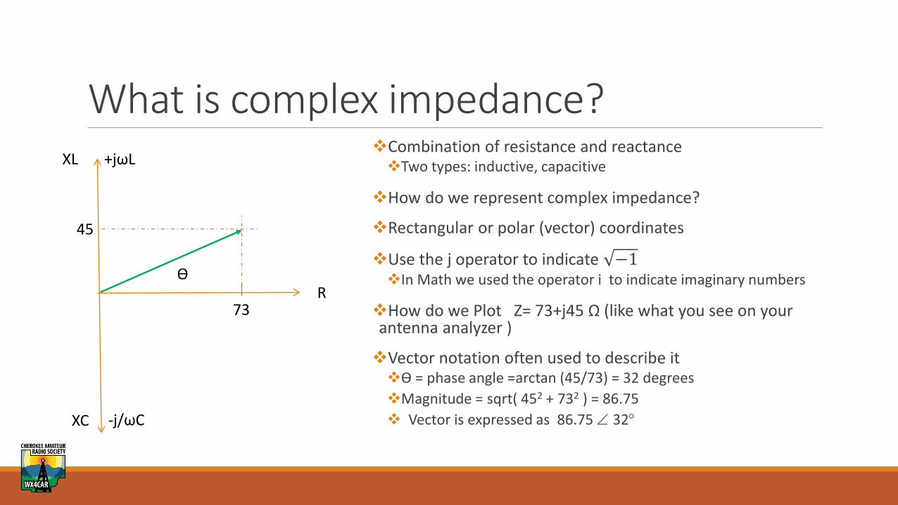
What is complex impedance?❖Combination of resistance and reactance❖Two types: inductive, capacitive
❖How do we represent complex impedance?
❖Rectangular or polar (vector) coordinates
❖Use the j operator to indicate −1❖In Math we used the operator i to indicate imaginary numbers
❖How do we Plot Z= 73+j45 Ω (like what you see on your antenna analyzer )
❖Vector notation often used to describe it❖ϴ = phase angle =arctan (45/73) = 32 degrees
❖Magnitude = sqrt( 452 + 732 ) = 86.75
❖ Vector is expressed as 86.75 32
R
-j/ωC
+jωLXL
XC
73
45
ϴ
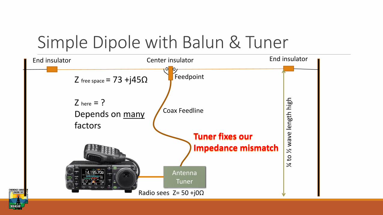
Simple Dipole with Balun & Tuner
AntennaTuner
Coax Feedline
Feedpoint
Center insulatorEnd insulator End insulator
¼ t
o ½
wav
e le
ngt
h h
igh
Z free space = 73 +j45Ω
Z here = ?Depends on manyfactors
Tuner fixes ourImpedance mismatch
Radio sees Z= 50 +j0Ω

Effects of Height on Antenna Impedance➢Black line = perfect earth (ground)
➢Green line = “average” earth➢Terrain affects impedance
➢Note the impedance at .25λ =~ 50Ω➢It is ~70Ω at the .5 wavelength height
➢Antennas at .25 wavelengths high have a characteristic impedance near 50Ω

Do I need a balun and why?➢In most cases YES, you should have a balun. ➢You can get lucky, but why chance it. ➢Best SWR you could get is 1.5:1
➢Balun = Balanced matching Unbalanced
➢Blocks RF from traveling on the coax shield
➢Is designed to match a balanced load (antenna) to an unbalanced load (coax and radio).
➢Optimum performance from your antenna
➢Some antenna tuners include one that typically connect to ladder line.
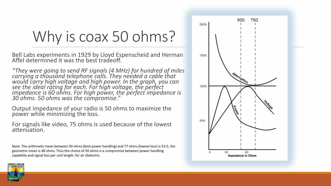
Why is coax 50 ohms? Bell Labs experiments in 1929 by Lloyd Espenscheid and Herman Affel determined it was the best tradeoff.
“They were going to send RF signals (4 MHz) for hundred of miles carrying a thousand telephone calls. They needed a cable that would carry high voltage and high power. In the graph, you can see the ideal rating for each. For high voltage, the perfect impedance is 60 ohms. For high power, the perfect impedance is 30 ohms. 50 ohms was the compromise.”
Output impedance of your radio is 50 ohms to maximize the power while minimizing the loss.
For signals like video, 75 ohms is used because of the lowest attenuation.
Note: The arithmetic mean between 30 ohms (best power handling) and 77 ohms (lowest loss) is 53.5, the geometric mean is 48 ohms. Thus the choice of 50 ohms is a compromise between power handling capability and signal loss per unit length, for air dielectric.

What about SWR*?➢Not the most important antenna measurement, but the easiest one to measure.
➢For our purposes it is best thought of as proportional to the impedance match between the radio and the antenna.
➢In reality it represents the ratio of the forward power to the reflected power on the transmission line.
➢It tell you nothing about how well an antenna is going to work. ➢ Even a dummy load has an SWR of 1:1!
➢Tells us the “health” of the feedline and antenna match. ➢A long lossy feedline can fool you with a low SWR.
➢SWR will generally go down with added height to the antenna
*Also called VSWR, or Voltage Standing Wave Ratio

SWR Effect on Power to the Antenna➢Usable SWR is really about 2:1
➢Most radios today can tune a 3:1 ratio with no problems
➢At > 2:1 SWR you lose significant power to the antenna
➢At 10:1 it’s 67% loss of power, ie you are just heating up the coax

What is an antenna tuner? Fundamentally it is an variable impedance matching circuit.
Circuits vary, but the diagram is a simple example
Makes the radio “see” the SWR is 1:1 at a particular frequency.
Do I need one?◦ Generally yes, unless you have an antenna and feed line
that are matched for the frequency you want to operate on.
◦ All multiband antennas need a tuner
◦ Some tuners also accept ladder line and have a 4:1 balun, which is needed for these types of feed systems.

Commercial Tuners➢Manual or automatic
➢In the shack versus remote tuning➢Why?
➢Power handling capability➢100 watts, 300 watts
➢600 watts, 1Kw and up

Antenna Radiation Pattern and DistanceHeight determines how far an antenna can “talk”
Dipoles are almost bidirectional
Directional antennas like Yagi, Hexbeam, etc help to be selective about what direction you talk/listen
Knowing something about this topic helps you understand why your antenna works the way that it does.
Distance ultimately depends on propagation and the ionosphere.
Takeoff angle is the angle with maximum radiation for a given antenna
Takeoff angle
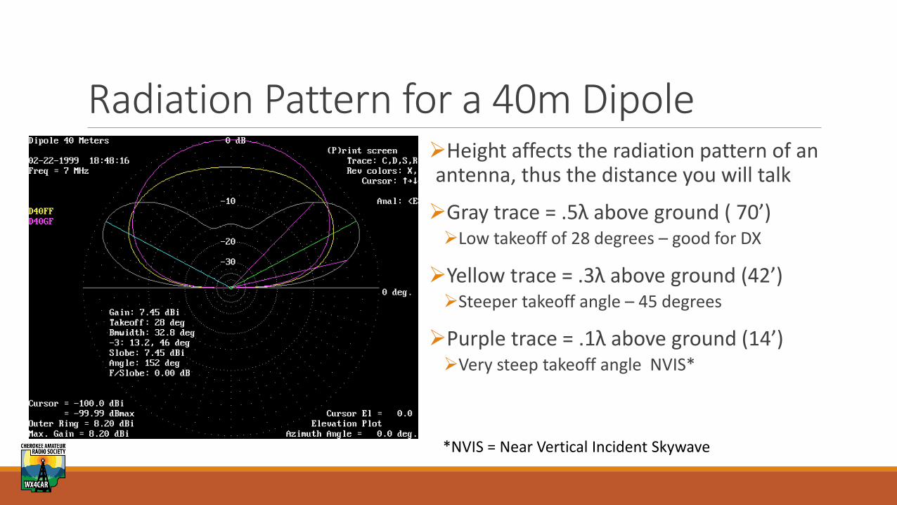
Radiation Pattern for a 40m Dipole➢Height affects the radiation pattern of an antenna, thus the distance you will talk
➢Gray trace = .5λ above ground ( 70’)➢Low takeoff of 28 degrees – good for DX
➢Yellow trace = .3λ above ground (42’)➢Steeper takeoff angle – 45 degrees
➢Purple trace = .1λ above ground (14’)➢Very steep takeoff angle NVIS*
*NVIS = Near Vertical Incident Skywave

Practical Antennas➢Good DIY project, but requires you have a way to “tune” the antenna.➢Access to an antenna analyzer helps a lot
➢Lot’s of inexpensive factory made antennas from sources like MFJ, Radiowavez, etc.
➢Most hams use simple antennas, like variations of a dipole
➢Elaborate antenna, like Yagi’s, Hex Beams, etc are expensive and not trivial to deploy➢Best performance requires a tall structures, like a tower➢Most often used by serious “contest stations”➢Can cost thousands of dollars➢Benefit is high gain focused in one direction
➢ALL antennas are a compromise when compared to the ideal case

ConclusionsAll antennas are a compromise in one way or another
Knowing what affects the performance helps you minimize the compromises
Test and experiment. That’s part of the hobby!
Learn more through ARRL publications, YouTube channels, and asking fellow hams
Most of all, be safe and have fun.

How well does my antenna work?➢Actual performance almost impossible to measure
➢Modeling the situation with software like EZNEC helps to understand what you have, in theory.
➢Understand the basic parameters governed by height, , antenna type, SWR, and propagation.
➢Test, test, test. Make contacts!➢Pay attention to where you are making contacts and plot them on
a map.
➢Refer to VOACAP and see if it correlates to known propagation
➢Use methods like WSPRNet to measure it.

Antenna Comparisons
➢Comparison of two G5RV antennas at two stations near each other
➢Propagation is virtually the same, so the comparison is very good
➢Antenna 1 is KB4MG at 35’ with falling away terrain
➢Antenna 2 is KK4NLK at about 33’ and flatter terrain
➢Both antennas perform well and average distance is > 5000 km at QRP power

Antennas in the real worldJim Millsap – to present some examples
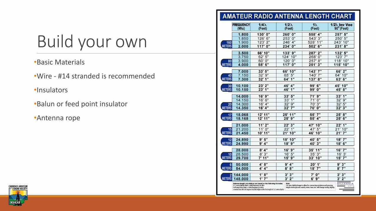
Build your own•Basic Materials
•Wire - #14 stranded is recommended
•Insulators
•Balun or feed point insulator
•Antenna rope