Space System Verification Program and Management...
38
AIAA S-117-2010 Standard Space System Verification Program and Management Process Warning This document is not an approved AIAA Standard. It is distributed for review and comment. It is subject to change without notice. Recipients of this draft are invited to submit, with their comments, notification of any relevant patent rights of which they are aware and to provide supporting documentation. Sponsored by American Institute of Aeronautics and Astronautics Approved XX Month 201X Abstract This document enforces a systematic approach to planning and executing verification programs for manned and unmanned space systems based on a distributed approach that corrects fundamental deficiencies associated with the traditional centralized verification approach. Thus, this document corrects generic problems in conducting verification that existed even during post-Total System Program Responsibility or “Faster, Better, Cheaper” policy that prospered late 1990 through early 2000 for developing complex space systems. This standard is intended to help those in the space community develop reliable systems that meet requirements while ensuring proper accommodations of heritage and/or commercial systems in their developing systems. It also helps to facilitate the closely coordinated
Transcript of Space System Verification Program and Management...

AIAA S-117-2010
Standard
Space System Verification Program and Management Process
Warning
This document is not an approved AIAA Standard. It is distributed for review and comment. It is subject to change without notice.
Recipients of this draft are invited to submit, with their comments, notification of any relevant patent rights of which they are aware and to provide supporting documentation.
Sponsored by
American Institute of Aeronautics and Astronautics
Approved XX Month 201X
Abstract
This document enforces a systematic approach to planning and executing verification programs for manned and unmanned space systems based on a distributed approach that corrects fundamental deficiencies associated with the traditional centralized verification approach. Thus, this document corrects generic problems in conducting verification that existed even during post-Total System Program Responsibility or “Faster, Better, Cheaper” policy that prospered late 1990 through early 2000 for developing complex space systems. This standard is intended to help those in the space community develop reliable systems that meet requirements while ensuring proper accommodations of heritage and/or commercial systems in their developing systems. It also helps to facilitate the closely coordinated

BSR/ AIAA S-117-201X
ii
validation activities with those of verification, as the distributed systems engineering processes utilized in the latter can be easily adopted by the former activities.

BSR/AIAA S-117-20XX
iii
LIBRARY OF CONGRESS CATALOGING DATA WILL BE ADDED HERE BY AIAA STAFF
Published by American Institute of Aeronautics and Astronautics 1801 Alexander Bell Drive, Reston, VA 20191
Copyright © 201X American Institute of Aeronautics and Astronautics All rights reserved No part of this publication may be reproduced in any form, in an electronic retrieval system or otherwise, without prior written permission of the publisher. Printed in the United States of America
BSR/ AIAA S-117-201X
iv
Contents Foreword ....................................................................................................................................................... vi
Introduction.................................................................................................................................................. viii
1 Scope ......................................................................................................................................... 1
2 Tailoring ..................................................................................................................................... 1
3 Applicable Documents and Reference Documents ................................................................... 1
3.1 Applicable Documents ............................................................................................................... 1
3.2 Reference Documents ............................................................................................................... 1
4 Vocabulary ................................................................................................................................. 2
4.1 Acronyms and Abbreviated Terms ............................................................................................ 2
4.2 Terms and Definitions ................................................................................................................ 3
5 Requirements for Space System (SS) Verification Program and Management Processes ..... 7
5.1 SS Verification Program ............................................................................................................ 7
5.2 SS Verification Plans ............................................................................................................... 10
5.3 Standardized Modular Distributed Verification Management Processes ................................ 11
5.4 Use of Distributed Verification Management Process for Late Changes and Heritage/Commercial Systems ................................................................................................ 17
Annex A A Typical Space System and an Example of WBS-WG-Based Verification Management Structure (Informative) ...................................................................................... 20
Annex B Review of Verification Plans for SS and Lower System Level, Including Those Developed by Subcontractor/Vendor (Informative) ................................................................. 21
B.1 Outline Requirements .............................................................................................................. 21
B.2 Document Delivery Requirements ........................................................................................... 21
B.3 Review of Requirement Flow-Down and Establishment of Specifications .............................. 21
B.4 Analysis, Test, Inspection, and Demonstration Plan for SS and Lower Level Systems (Based on VCRM Process) ..................................................................................................... 22
B.5 I&T Plans for the SS and Lower Level Systems...................................................................... 22
B.6 ISDVL Plans for the SS Element, Segment, Module, System, Unit, and Contractor/Subcontractor/Vendor ............................................................................................ 23
B.7 SS and Lower Level Systems Sell-Off and Consent-to-Ship Data Package .......................... 23
B.8 Verification Issue/Watch List Management Plan for SS, Segment, Higher Level External IF, and Module .......................................................................................................... 24
Annex C Deliverable/Review Documents Associated With Each Distributed Verification Management Process (Informative) ....................................................................................... 25
Annex D Required Minimum Contents of Individual Specification Dedicated Verification Ledger (ISDVL) (Informative) .................................................................................................. 26
Annex E Check List for Planning and Executing Late Changes, Heritage, or Commercial System Applications (Informative) ........................................................................................................ 28
E.1 Scope ....................................................................................................................................... 28

BSR/AIAA S-117-20XX
v
E.2 Checklist for Planning and Executing Late Changes, Heritage, or Commercial System Applications: Requirement/CONOPS Related ........................................................................ 28
E.3 Checklist for Planning and Executing Late Changes, Heritage, or Commercial System Applications: Design and Analysis Related ............................................................................ 28
E.4 Checklist for Planning and Executing Late Changes, Heritage, or Commercial System Applications: Manufacturing Related ...................................................................................... 29
E.5 Checklist for Planning and Executing Late Changes, Heritage, or Commercial System Applications: System Integration and Test Related ............................................................... 30
E.6 Checklist for Planning and Executing Late Changes, Heritage, or Commercial System Applications: Piece Parts and Materials Related .................................................................... 30
Figures
Figure A.1– Example of Verification Management Structure ...................................................................... 19
Tables
Table C.1 – Space Systems Verification Program and Plan Developments & Reviews Requirements for Prime Contractor, Subcontractors, and Vendors..................................................................... 25
Table D.1 – Required Minimum Contents of Individual Specification Dedicated Verification Ledger (ISDVL) ........................................................................................................................ 27

BSR/ AIAA S-117-201X
vi
Foreword This standard has been developed by the AIAA Systems Engineering Committee on Standards (SECoS) under the auspices of AIAA Standard Executive Council (SEC). The standard delineates a specific set of requirements for each space program to successfully plan and execute verification of a space system based on a “distributed” verification program and associated processes. In particular, this standard uniformly applies to the verification of space and launch vehicles, ground systems and associated devices, units, subsystems and internal/external interfaces regardless of builders that are engaged in the development of these components. Adhering to the requirements specified in this standard by each space program is important in order to prevent/minimize late changes and misuse of heritage/commercial systems that are typically very costly and in the worst case can cause post-launch mishaps. The required “distributed” verification program and its processes also facilitate implementation of “distributed” validation activities such as those conducted by third party participants in the work breakdown based integrated product team (WBS-IPT), Development Test and Evaluation (DT&E), Operational Test and Evaluation (OT&E), or Independent Readiness Review (IRR) teams. This AIAA standard was developed as the result of a series of reviews by the SECoS, and the general public. At the time of approval, the members of the AIAA SE Committee on Standards who developed this standard were:
Satoshi Nagano, Chair The Aerospace Corporation
John Hsu, Co-Chair The Boeing Company
John C. Muehibauer, Co-Chair Lockheed Martin Aeronautics Company
Michelle Bailey DAU South
Dexter Lee Blackstock NASA Langley
Shirley Brandt Jacobs Engineering
Edmund H. Conrow Management and Technology Associates
John W. Dahlgren MITRE
John Day Inspace Systems
Mahantesh Hiremath Space Systems Loral
Stephen Jensen NASA Dryden Flight Research Center
Eric E. Nichols Orbital Science Corporation
Brian Selvy Paragon Space Development Corporation
William W. Vaughan University of Alabama in Huntsville

BSR/AIAA S-117-20XX
vii
The above SECoS consensus body has submitted this document to the AIAA Standards Executive Council (SEC) for their review on (TBD date). The above consensus body approved this document in Month 201X.
The AIAA Standards Executive Council (Wilson Felder, Vice President) accepted the document for publication in Month 201X.
The AIAA Standards Procedures dictates that all approved Standards, Recommended Practices, and Guides are advisory only. Their use by anyone engaged in industry or trade is entirely voluntary. There is no agreement to adhere to any AIAA standards publication and no commitment to conform to or be guided by standards reports. In formulating, revising, and approving standards publications, the committees on standards will not consider patents that may apply to the subject matter. Prospective users of the publications are responsible for protecting themselves against liability for infringement of patents or copyright or both.
BSR/ AIAA S-117-201X
viii
Introduction
It is critical for each space system (SS) acquisition program to follow a standard set of management processes that enforce the “system is built right” verification approaches in order to develop reliable systems. This is based on survey evidence indicating that most costly “late changes” or post-launch mishaps could have helped to prevent by implementing a thorough verification program. The findings show such a program is needed throughout early development activities and through to delivery of the developed system to the launch site (see Reference 1). This document outlines a distributed verification program, as a space system community standard that implements a set of six verification management processes at every level and phase of a system’s development as follows: • VM-Process 1: Requirement flow-down and establishment of specification process • VM-Process 2: Verification cross-reference matrix (VCRM) process • VM-Process 3: Integration and test (I&T) process • VM-Process 4: Individual specification dedicated verification ledger (ISDVL) process • VM-Process 5: Sell-Off/Consent-to-Ship process • VM-Process 6: Verification-related risk management process When applied, these management processes enforce verification approaches that are consistent and uniform among all the space systems’ builders. These processes also enable and enforce each system developer to conduct proactive and continual risk management. This includes the use of issue and/or watch lists to help identify and resolve concerns at the earliest phase and lowest level of the system being developed. This distributed verification process, if applied at the start of a program, will also ensure thorough re-verification of any late changes that might occur. Furthermore, this standard will also help each space program to properly apply any heritage/commercial systems to a new program as it helps them to examine whether these systems have been thoroughly verified by comparing them against the distributed verification program and its processes. If not, appropriate modifications for new applications will be systematically accomplished by applying these six verification management processes. Although this standard focuses on system verification, it includes some requirements for system validation because of the close relationship between verification and validation. Frequently, material developed for verification is also applicable to validation efforts.

BSR/AIAA S-117-200X
1
1 Scope This standard establishes a set of requirements for planning and executing verification programs for both manned and unmanned space systems. This standard enforces the distributed verification program among general space system builders that engage in the development of any components of a space system, starting at the lowest level (i.e., unit level) and the earliest phase (i.e., requirement phase) through to the sell-off and the consent-to-ship of a system’s development. Although space systems generally include all or combinations of five segments—Space Segment, Launch Segment, Ground Segment (GS), User Segment, and Satellite Control Network Segment—this standard primarily addresses verification associated with space segment, launch segment, and ground segment acquisitions. The standard may, however, be adapted to the remaining two space systems: the user segment and the satellite control network segment. Other launch segments including range safety, ground support equipment, and launch operation facilities, which are not otherwise addressed in this document, may also benefit from the management processes. This standard is applicable for the procurement of space systems, including space vehicles, launch vehicles, ground systems and associated equipment/subsystems.
2 Tailoring In order to better support a specific program or project, the processes defined in this standard may be tailored to match the actual requirements or needs of the particular organization. Any tailoring of this document, if included as a compliance document, should be coordinated with/approved by the procuring authority or customer.
NOTE Tailoring is a process by which individual requirements or specifications, standards, and related documents are evaluated and made applicable to a specific program or project.
3 Applicable Documents and Reference Documents 3.1 Applicable Documents These documents should support a specification by including additional guidance on the verification method, approach, and success criteria, and by promoting compliance through design, analysis, manufacturing, test, and system acceptance at each level of the system’s development.
3.2 Reference Documents Reference documents are defined as documents that are not contractually binding but that may contain useful or supporting information. A list of references used for developing this standard is as follows:
Reference 1: AIAA 2007-6099 Solid Verification Program Enables Cost-Effective Acquisition of Complex yet Reliable Space Systems, September 2007
Reference 2: INCOSE Systems Engineering Handbook Version 3.1, August, 2007
Reference 3: NPR 7123.1 NASA Systems Engineering Processes and Requirements, March 26, 2007
Reference 4: ANSI/EIA-632 EIA Standard, Processes for Engineering a System, 1999

BSR/AIAA S-117-200X
2
Reference 5: MIL-STD-1540E, SMC-S-016 Test Requirements for Launch, Upper-Stage, and Space Vehicles
Reference 6: ISO 17666:2003, Space systems—Risk management
Reference 7: Edmund H. Conrow, “Risk Management for Space Systems.” Paper to the Aerospace Corporation/Air Force SMC/NASA Seventh National Symposium on Space Systems Engineering & Risk Management Conference, 27-29 February, 2008
Reference 8: MSFC-HDBK-2221 NASA Verification Handbook, Vols. 1 & 2, February, 1994
Reference 9: Test and Evaluation Management Guide, The Defense Acquisition, University Press, January, 2005
Reference 10: NASA-STD-7009 The NASA Standard for Models and Simulations, July 2008.
Reference 11: AIAA S-110-2005 AIAA Standard for Space Systems—Structures, Structural Components, and Structural Assemblies
Reference 12: Critical Clearances in Space Vehicles, Aerospace Report No. ATR-2009 (9369)-1, June 2008, developed by the U.S. Government–Industry National Security Space Mission Assurance Improvement Workshop
Reference 13: Guideline for Space System Late Changes Verification Management, Aerospace Report No. TOR-2008 (3901)-7822, June 30, 2008, developed under the auspice of the Sr. Executive U.S. Government–Industry National Security Space Mission Assurance Improvement Workshop
Reference 14: Air Force Space Command Manual 91-710 Range Safety User Requirements, July 2004
4 Vocabulary 4.1 Acronyms and Abbreviated Terms
AIAA American Institute of Aeronautics and Astronautics CDR Critical Design Review CDRL Contract Data Requirements List CONOPS Concept of Operations COTS Commercial, Off-the-Shelf (COTS) DID Data Item Description DT&E Development Test and Evaluation FCA Functional Configuration Audit FRB Failure Review Board GE Ground Element GIDEP Government Industry Data Exchange Program GS Ground Segment GTE Ground Terminal Equipment I&T Integration and Test IF Interface IPT Integrated Product Team IRR Independent Readiness Review IRRT Independent Readiness Review Team ISDVL Individual Specification Dedicated-Verification Ledger
BSR/AIAA S-117-200X
3
LCC Late Change Category LV Launch Vehicle MRR Manufacturing Readiness Review OT&E Operational Test and Evaluation PCA Physical Configuration Audit PDR Preliminary Design Review PMPCB Parts, Materials, and Processes Control Board QA Quality Assurance SATCOM Satellite Communications SCN Satellite Control Network SDR System Design Review SE Systems Engineering SEC Standards Executive Council SECoS Systems Engineering Committee on Standards SRR System Requirements Review SS Space System SV Space Vehicle TLYF Test Like You Fly TPRD Test Parameters Requirements Document TRR Test Readiness Review VCRM Verification Cross-Reference Matrix VM Verification Management WBS Work Breakdown Structure WG Working Group 4.2 Terms and Definitions For the purposes of this document, the following terms and definitions apply.
4.2.1 System-related definitions
Component generic term used in this specification to refer to any part of a space system including element, subelement, subsystem, unit, or interfaces
NOTE Component may be referred to as piece parts in some literature; however, it is generically used to refer to any part of a system in this standard (i.e., all systems, in general, have multiple components that require multiple level of integrations).
External interfaces (external IFs) physical and operational connections originating with the developed system and terminating with other systems at the same or higher levels of integration
NOTE External IFs normally relate to interfaces between systems that are developed or used by different agencies, customers, or contractors. These IFs are in general defined through interface requirement documents (IRDs) that capture both technical and programmatic requirements for the IFs. Subsequently, interface control documents (ICDs) that capture more detailed technical requirements will be developed in order to design development systems that satisfy these requirements.
Ground segment earth-bound portion of a Space System mission

BSR/AIAA S-117-200X
4
NOTE Satellite Control Networks (SCN), such as Air Force SCN as well as Satellite Communications (SATCOM) Terminals, are also considered as a part of Ground Segment. These Networks/Terminals perform transmission of commands, data uploads, vehicle control, telemetry receipt, and data processing. They perform these functions using operational control nodes, satellite operations centers, geographically dispersed remote tracking stations/terminals, antennas, and networks to connect the many elements.
Ground support equipment earthbound equipment, in addition to the launch pad facilities, that are required by a specific launch vehicle
NOTE Ground support equipment excludes the user segment equipment used for communications, control, and data processing of the space system vehicle and its payload.
Internal interfaces (Internal IFs) physical and operational connections between components within a system
NOTE Internal interfaces generally refer to component-to-component interfaces such as those within space launch vehicles or ground stations that are built for the same customer. However, space vehicle-to-ground or space vehicle-to-launch vehicle interfaces could be referred to as external interfaces for space vehicles, launch vehicles, or ground station builders, even though these components are built for the same customer.
Launch segment portion of the space system mission in which the space vehicle is transported from the ground to its operational orbit
Launch segment equipment used for transporting space vehicle(s) to their operational orbit(s)
NOTE The Launch segment equipment can include the launch vehicle, launch-related Ground Support Equipment, launch pad facilities, Range Safety systems, and any launch control operations.
Space segment refers to the ex-atmospheric portion of the Space System Mission
NOTE The Space Segment may employ equipment, such as the space vehicle, post-launch maneuvering system, and any other space-based systems needed to perform the identified tasks during the space segment.
Space systems (SS) consists of equipment and/or people that are employed during the ground, launch, space, and user segments to perform coordinated tasks to achieve the objective of a space systems mission
NOTE This standard’s focus is on the verification management associated with the space segment, launch vehicle, and ground segment including satellite control network terminals such as those belonging to the Air Force SATCOM system.
Space system (SS) mission consists of ground, launch, space, and user segments in which predetermined tasks are performed in a coordinated manner to achieve a specific objective or mission
Space vehicle generally consists of the spacecraft bus, payload (such as for observation or detection sensors, communication relay modules, etc.), associated subsystems, units, and the internal and external interfaces
User segment The portion of a Space System Mission in which the collective group of government agencies or commercial entities (organizations and individuals) uses and controls the space segment payload and its products

BSR/AIAA S-117-200X
5
NOTE The user segment consists of data receiving and processing equipment, the raw or processed data, and the distribution system used to get the data to the customer.
4.2.2 System verification and validation related definitions
Integration and test (I&T) used to verify that a manufactured component (or combinations of components) satisfies the functional/performance requirements specified in their specifications. I&T will also be used for engineering, acceptance, or qualification tests.
NOTE This standard will reference the following seven levels of integration and tests: (1) Space System, (2) Element (space vehicle, launch vehicle, ground station), (3) Subelement (payload, spacecraft bus), (4) subsystem, (5) unit or Line Replaceable Unit (LRU), (6) internal and external interface (IF), and (7) piece parts and materials.
System verification system verification addresses whether the overall system and its components, including interface, satisfies each specification, that is, the verification ensures the conformance to each requirement of their specifications; that the system has been built right (Reference 2)
System verification program and process verification program and its processes ensure that the design, as produced, has resulted in a physical product that satisfies every requirement of a specification with the proof and traceable documentations
NOTE 1 The verification program and its processes must be applied to ensure that each component specification and associated requirements are properly established, and designs and analyses, manufacturing, and tests are properly completed with the documented evidence to show the proof of satisfaction against every requirement at its sell-off.
NOTE 2 Writing the verification requirements is an integral part of establishing the performance, functional, and other requirements that are recorded in specifications.
Test Like You Fly (TLYF) verifies the planned flight sequences, timelines, command operations, data and telemetry downlinks, and deployments functions are tested under Flight Like operations and configurations. The phrase “Test As You Fly” is intentionally avoided in this document because it is almost impossible to conduct tests exactly “as you fly” but “like you fly.”
Validation confirm that each system level as built (or as it will be built) satisfies the stakeholders’ stated needs NOTE 1 Requirement validation confirms the "right system is being built" (Reference 2). NOTE 2 In addition to Reference 2, other systems engineering standards, handbooks or papers such as Reference 3 and 4 are recommended for the general definitions of verification and validation (V&V). NOTE 3 Stake holders differ depending on the level system being validated (i.e., the stake holders for the top level system include the system acquirers), and those for lower level systems may, for example, be just the contractor and customer program offices or prime contractor for subcontractors. NOTE 4 Validation activities, in general, involve third (independent) party, end users, or customer representatives. As such, any third party reviews and evaluations, and the work that was completed by the system builder, are considered as a part of validation activities. The types of work completed by the builder include those relating to specifications, design and analyses, tests, inspections, and demonstrations.
BSR/AIAA S-117-200X
6
Verification artifact documents satisfaction of a specific, or set of requirement(s)
NOTE The verification artifact used to demonstrate requirement compliance must align with the assigned verification method.
Verification by analysis use of modeling and analytical techniques to predict a design’s compliance to the requirements based on calculated data or data derived from lower level component or subsystem testing
NOTE Analyses performed in support of design requirements are normally available as early as Preliminary Design Review (PDR) and are in general finalized in the Critical Design Review (CDR), although some analyses require some integration and test results that may be performed post-CDR.
Verification by demonstration system operation to show requirement’s qualitative compliance or achievements such as safety, when the requirement lacks specific quantitative detail or measurable values
NOTE Some examples of “verification by demonstration” include qualitative evaluation of transportability, serviceability, accessibility, other human engineering, and maintainability items including such item as mean time to repair generally based on pass/failure criteria.
Verification by inspection the visual examination of the system, subsystem, unit, and IFs to verify design features or specific characteristics verifiable through other methods
EXAMPLE Some examples of “verification by inspection” are
– Evaluating physical characteristics such as dimensions, features, spacing/layout of wires, clearances/separations between hardware,
– Ensuring appropriate documentations such as relating to software configurations, engineering drawings,
– Checking pass/failure criteria of a tested parameter. Verification by test utilized for verifying the satisfaction of each applicable requirement by conducting tests such as – Proof of concept or preliminary performance/characteristics of a newly developing system/piece part
using prototype, brass board, or engineering modules prior to implementing into actual flight system applications (i.e., development tests)
– Life capabilities of equipment /piece parts such as batteries, new piece parts, or solar array coupons under simulated flight environments (i.e., life tests)
– The acceptability and qualification of the designed and manufactured flight systems under acceptance /qualification level test environments and sequences such as Acceptance Tests, Qualification Tests, and Protoqual Tests.
NOTE See Reference 5, MIL-STD-1540E, Test Requirements for Launch, Upper-Stage, and Space Vehicles, for definitions of Acceptance Tests, Qualification Tests, and Protoqual Tests.
BSR/AIAA S-117-200X
7
Verification methods categorize the verification artifacts used to assist in the product’s production, to schedule the appropriate resources, and to help identify when the documentation will be available for review
NOTE Four basic verification methods are defined that cover all method subcategories. Completion of each listed method is nominally associated with a specific phase of the program. 4.2.3 Issues and watch list related definitions Issues list items related to requirement verification, design and analysis, manufacturing, test and system acceptance processes, and activities that pose problems
NOTE 1 Issue list items generally require immediate resolution by integrated product teams or working groups. The time-frame for addressing issues is often short. A suitable assessment (identification, including root cause and analysis) must be performed and handling strategy selected and implemented to address each issue. Issue item that cannot be resolved within a lower level component development team will normally be raised to a higher system/program management team/Risk Management Board that address the unresolved issue using risk management process.
NOTE 2 See Reference 6, “ISO 17666:2003, Space systems—Risk management” for general principles and requirements for integrated risk management on a space project. It explains what is needed to implement a project-integrated risk management policy by any project actor, at any level (i.e. customer, first-level supplier, or lower-level suppliers).
NOTE 3 Using risk management terminology, Risk = Probability (p) times Consequence (C), where 0 < p < 1 and C > 0, and time-frame is in the future. Issue is p = 1, C > 0 and time-frame is in the future. A problem is p = 1, C > 0, and time-frame is now (current). (See Reference 7.)
Watch list programmatic and technical concerns that can be binned into categories that can be generally resolved within an individual WBS based Working Group (WBS-WG). Watch list items can be elevated to issues and for consideration as program-level risks should insufficient progress be made in resolving these concerns within a WBS-WG in a timely manner.
NOTE Classifying concerned items as either a “watch” or “Issue” item in general requires discussions between cognizant engineers and managers, or among appropriate integrated product team/working group members. 5 Requirements for Space System (SS) Verification Program and
Management Processes 5.1 SS Verification Program Each space program, manned or unmanned, shall establish a SS distributed-verification program in order to manage thorough verification activities by implementing a standard set of verification management (VM) processes at every level and phase of system development as specified in 5.2 and 5.3. NOTE 1 Verification activities in this context will apply to planning and executing activities starting at the requirements definition phase and extending through the sell-off phase. NOTE 2 NASA Verification Handbook, MSFC-HDBK-2221, Vol. 1 and 2 (Reference 8) are recommended for use in developing a SS verification program. The guidelines in the Handbook will assist in defining the “Distributed” verification program described in this standard.
BSR/AIAA S-117-200X
8
5.1.1 Verification management by integrated product team or working group
The distributed-verification program shall utilize Integrated Product Teams (IPT) or Working Groups (WG) that are formed in alignment with the program’s Work Breakdown Structure (WBS) to manage the verification of the component(s) that they are responsible for throughout the development phase.
NOTE 1 IPT and WG are used synonymously in this case although the latter, in essence, will be a smaller IPT. Reference 2 and 3 provide detailed explanations regarding the formation and processes associated with IPTs. This standard will refer to IPTs as WBS-WGs throughout this document.
NOTE 2 WBS Model describes a system that consists of end products and their subsystems (perform the operational functions of the system), the supporting or enabling products (for development; fabrication, assembly, integration, and test; operations; sustainment; and end-of-life product disposal or recycling), and any other work products (plans, baselines) required for the development of the system (see Reference 2). NOTE 3 See Annex A for an example of a required WBS-WG based Verification Management (VM) structure. NOTE 4 The development phase of a program in this context encompasses those phases starting from authority to proceed (ATP) after contract award to requirements flow-down/specification development, design/analysis, manufacturing, and test (including factory and launch site tests), and sell-off phases. On-orbit test is considered as a part of the validation activities (Right system is built) and not addressed in this document. NOTE 5 The formation of WBS-WGs enables well-coordinated and integrated verification activities for each individual component as well as the overall system that are being developed. Each WBS-WG will be populated by representatives from the other WBS-WGs as well as third parties such as the customer or contractor’s other organizations external to those developing the system. This WBS-WG will be active on a continual basis throughout the development and delivery phases of its responsible system.
5.1.2 Verification management board or equivalent review board
The SS verification management or equivalent review board shall be formed to officially ensure that (1) WBS-WG activities are properly planned and executed such that their activities are consistent with the overall verification program and (2) configuration management is properly applied for WBS-WG activities and the overall verification program. NOTE 1 SS Verification management board or equivalent review board may be formed under a subset of program management or other review boards as long as it accomplishes the aforementioned review activities and associated configuration management for their verification program.
5.1.3 SS verification program flow-down to subcontractors and vendors The requirement for establishing the verification program and verification management process described in 5.1 shall be flowed-down from the prime contractor to the subcontractors and vendors. NOTE This requirement is to ensure that every level of system development implements a standard set of verification management processes regardless of where the systems or lower-level systems are developed. 5.1.4 Verification activities coordinated with other review boards
Each of the WBS-WG based verification activities shall be conducted by closely working with such programmatic and technical review boards such as Requirement Change Board, Configuration Control
BSR/AIAA S-117-200X
9
Management Board, Program Risk Management Board, Power-Weight Management Board, Parts, Materials and Processes Control Board, Failure Review Board as well as Quality Assurance Management Board. NOTE SS-Verification Management Board or equivalent review board will facilitate well coordinated verification activities with other discipline groups. 5.1.5 Coordination with validation activities including Development Test and Evaluation (DT&E),
Operational Test and Evaluation (OT&E), and Independent Readiness Review (IRR) Teams The flight system acquiring office and the builders shall provide documented proof of verification activities and results that are developed based on “distributed” program and processes (see 5.2 and 5.3) to multiple validation teams upon their requests. These validation teams include third party participants in each of the verification WBS-WG as well as Development Test and Evaluation (DT&E), Operational Test and Evaluation (OT&E), and Independent Readiness Review (IRR) teams (IRRT). NOTE It should be noted that WBS-WG verification programs facilitate them to conduct effective validation activities along with the verification activities by virtue of third person participations in the WG, These third parties confirm the validity of the verification results based on their independent assessments for each WBS-WG areas at appropriate phase and level of the program being developed. These validation activities may be accomplished by means of independent analysis, test, inspection, or demonstration. 5.1.5.1 Development Test and Evaluation (DT&E) and Operational Test and Evaluation (OT&E)
Support If the Development Test and Evaluation (DT&E) process is contractually required, then the I&T plan shall include a plan for accomplishing the required DT&E. Most of the non-mass production type space programs require plans for accomplishing the flight system production phase DT&E. If the Operational Test and Evaluation (OT&E) process is contractually required, then a separate OT&E plan is required that addresses early and formal on-orbit test as a formal sell-off process to the system acquirer. NOTE The Test and Evaluation Management Guide from the Defense Acquisition University Press (Reference 9) is recommended for use in developing and executing the DT&E and OT&E Plans.
5.1.5.2 Independent Launch Readiness Review support The flight system acquiring office and the builders shall provide documented proof of verification such as the ISDVL (see 5.3.4), As-Tested Data (see 5.3.3.6), and any test discrepancies (see 5.3.3.5) upon request by the associated Independent Readiness Review/Independent Launch Readiness Review Teams. NOTE 1 IRR is normally held at the time of space vehicle or launch vehicle consent to ship to launch site, and/or as a launch readiness reviews. It is imperative for each WBS-WG team to adhere to the Standardized Modular-Distributed Verification Management Processes delineated in 5.3 in order to be able to fully satisfy these IRR activities. NOTE 2 It is also a common practice for customer/stakeholders to form a third party launch readiness review team that is independent of the system acquiring agency/program offices and the builders to ensure/certify that the flight system is ready to be launched.
BSR/AIAA S-117-200X
10
5.2 SS Verification Plans
A verification plan that implements the verification management approach and processes as described in 5.1.1 and 5.1.2 shall be developed for each of the SS, element (space vehicle, launch vehicle and ground element), subelement (or module such as spacecraft bus or payload), subsystem, and unit. A sample contract data requirements list (CDRL) is provided in Annex B that incorporates a set of detailed plans for the verification management processes explained in 5.3. NOTE 1 Each of the component’s verification plans may be combined and captured in a limited number of documents to achieve better efficiency. A system verification plan, for example, may capture those relating to the top system, whereas space/ground/launch element verification plans may encompasses element-to-unit end-to-end verification activities. NOTE 2 Verification plans for external and internal interfaces must also be developed. It should be noted that external interfaces control documents (ICDs), in general, will be developed based on bilateral agency-to-agency, or contractor-to-contractor agreements that are captured in interface requirement documents (IRD). Space-ground, Space vehicle-Launch vehicle, and Space vehicle-Payload ICDs may be typical examples of external ICDs. Internal ICDs normally refer to requirements relating to Space vehicle–payload and internal space vehicle subsystem-to-subsystem interfaces. NOTE 3 It is recommended that NASA Standard for Models and Simulations, NASA-STD-7009 (Reference 10) be used as a guideline for writing requirements and associated verification approaches for the technical disciplines described in the standard. This standard was specifically developed in response to an action identified in the Columbia Accident Investigation Board (CAIB) Report. Some of the key features of this standard are requirements and recommendations for verification, validation, uncertainty quantification, training, credibility assessment, and reporting to decision makers; also included are the cross-cutting areas of documentation and configuration management. NOTE 4 It is also recommended that NASA Verification Handbook, MSFC-HDBK-2221, Vols. 1 & 2 (Reference 8) be used as guidelines for developing detailed verification planning for different technical disciplines such as structure/mechanical, electrical, software, attitude determination and control, etc.
5.2.1 Verification Plan for Systems Developed by Subcontractor and Vendor A separate verification plan shall be developed for systems that are developed by subcontractors and vendors.
5.2.2 Review of Verification Plans
The content of the plans and the execution progress status of each SS Verification plan including those developed by subcontractors and vendors shall be reviewed at each of their corresponding review milestones that include System Requirements Review (SRR), System Design Review (SDR), Preliminary Design Review (PDR), Critical Design Review (CDR), Manufacturing Readiness Review (MRR), Test Readiness Review (TRR), and Sell-off Review. Note 1 Annex B.1 and B.2 provide a general outline of a verification plan that will be included in the Data Item Description (DID) referenced in a CDRL calling for the plan.
BSR/AIAA S-117-200X
11
Note 2 Annex C provides documents deliverable/review requirements associated with each distributed verification management process that will be included in the Data Item Description (DID) referenced in a CDRL calling for the plan. 5.3 Standardized Modular-Distributed Verification Management Processes Each SS and lower-level systems developer shall implement a standardized modular-distributed management processes detailed in 5.3.1 through 5.3.6 as follows: 5.3.1 VM Process 1: Requirement flow-down and establishment of specification process The developers of each level of the system, in coordination with their systems engineering (SE) organizations, shall be responsible for developing a specification with both performance and verification requirements for their system by (a) capturing the requirements that are flowed down from the top level SS, elements, and external interface specifications to their developing system; (b) capturing all the “derived” and specific requirements that are necessary to design and develop their system; and (c) capturing/modifying all the heritage system requirements that are compatible with the top-level requirements determined by the requirements flow-up process. The plan and results of the requirement flow-down/ flow-up from the top system level to the lowest unit level specifications and vice versa shall be delivered for review at each corresponding system level’s SRR, SDR, PDR, and CDR. NOTE 1 One of the most critical parts of the distributed verification program is to ensure that a thorough and solid specification is established for each level of a system being developed. This will be accomplished if the system developer for each level takes responsibility/ownership of developing their specifications in coordination with their systems engineering organization. This approach is to ensure that requirement establishment and associated verification activities are well integrated. NOTE 2 In particular, each specification needs to include sections relating to (a) the function, performance, constraints, and quality requirements for the product and (b) a detailed statement of the verification requirements for each separate requirement in the former section. It should be noted that the lack of a detailed descriptions in the latter section in specs caused several costly late changes and post-launch failures. NOTE 3 Each of the top SS level requirements flowed down shall have documented traceability to the lowest level preferably using requirement flow-down (i.e., derived requirements) tracking computer program. NOTE 4 Each level of system developer shall ensure that their specifications also captured all the non-derived requirements that are specific to each of the systems being developed NOTE 5 Each level of system developer, if they used “heritage” system, shall ensure that they perform requirement flow-up activities to ensure that each of the requirements in the heritage system specification is compatible with and support the top-level system requirements. If not, then they shall modify non-compliant requirements accordingly. NOTE 6 Each of the requirements shall be well defined and objectively verifiable. NOTE 7 Each of the compliance documents shall also be properly flowed down from the top level specification to any of the applicable lower level specifications.
BSR/AIAA S-117-200X
12
NOTE 8 The system level requirements need to be under CM control upon completion of SRR. Lower level requirements may be delayed in going under CM control until PDR. NOTE 9 These requirement flow-down and flow-up processes may preferably utilize computer data management software in order to effectively manage hundreds of top system level requirements flowed down to numerous lower level systems. NOTE 10 Validation of the developed specification may be considered as completed after independent subject matter experts from external organizations have reviewed the specification and their comments are incorporated into the specification. NOTE 11 Annex B.3 provides a general outline and delivery requirements for review relating to this activity of a verification plan that will be included in the Data Item Description (DID) referenced in a CDRL calling for the plan. 5.3.2 VM Process 2: Verification Cross-Reference Matrix (VCRM) process 5.3.2.1 Verification method assignments Verification method(s) and associated verification approaches shall be developed for each requirement of a specification and reviewed at each corresponding SRR, SDR, PDR, and CDR as follows: – The verification method shall be: analysis, test, inspection, demonstration, or any combination of these
methods. – The verification method selected for each requirement shall be the most effective and accurate method
to verify the satisfaction of the requirement as well as the associated upper level requirements. – A synopsis and rationale for the actual implementation approaches shall be documented for each
requirement. NOTE See 4.2 for definitions of “Verify by Analysis,” “Verify by Demonstration,” “Verify by Inspection,” and “Verify by Test.” 5.3.2.2 VCRM process plan for the SS and the lower level systems Verification plans (whether employing analysis, test, inspection, demonstration, or combinations of these methods) for the SS, and all the lower level systems, including external and internal IFs, shall be delivered for review at SRR, SDR, PDR, and CDR. The applicable plans shall also be delivered for review at MRR and TRR. NOTE Annex B.4 provides a general outline and delivery requirements for review relating to this activity of a verification plan that will be included in the Data Item Description (DID) referenced in a CDRL calling for the plan. 5.3.2.3 Verification by analysis—planning and execution Design and analysis documents shall be developed for each level of system being developed (be it for a system, element, subsystem, or unit, etc.) and ensure that all the “verify by analysis” requirements in the corresponding specification are properly documented and satisfied – A list of analyses along with the approaches and methods, and a set of Design Reference Cases and
other conditions for each analysis used for “verification by analysis” shall be identified and documented.
BSR/AIAA S-117-200X
13
– A list of “verify by test” that require development test to support the design analysis shall also be included in the design and analysis list. It should be noted that most of the requirements that are assigned “verify by test” using development test are also assigned with “verify by analysis.”
– Determination that the completed design and analysis satisfy all of the “verify by analysis” requirements in the corresponding specification will be one of the pass/failure criteria for the associated PDR and CDR.
5.3.2.4 Verification by test—planning and execution A list of tests along with the approaches/methods (such as with the use of flight units, engineering units, breadboard, coupons, software/hardware-in-the-loop test, etc.), and test conditions for “verification by test” shall be documented and reviewed at corresponding system’s PDR, CDR and TRR. – “Verify by test" requirements that will be verified based on development hardware/software or
breadboard testing are normally required to substantiate related analyses or vice versa as explained in 5.3.2.3. These development test lists, approaches, and results will normally be reviewed along with the associated analyses.
– “Verify by test" requirements that will be verified under the acceptance/qualification tests will be listed in the test parameters requirement document (TPRD) and incorporated into the corresponding test plan that will be developed based on VM-Process 3, explained in 5.3.3.
5.3.2.5 Review of verification by inspection and demonstration list, approaches, and results A list and detailed approaches for “verification by inspection” and “verify by demonstration” shall be developed for each of the applicable SS and lower level system specifications. These lists, approaches, and progress shall be reviewed at appropriate review milestones such as PDR, CDR, MRR, TRR, and sell-off for each applicable system. 5.3.2.6 Review of verification plan of critical clearances A verification plan for critical clearances shall be developed and executed to ensure that critical clearances related requirements and criteria for any deployable systems are properly established, designed, manufactured, and tested. NOTE 1 Reference 11, AIAA S-110-2005 (Structures), and Reference 12, Critical Clearances in Space Vehicles are recommended guidance document for developing a verification plan for critical clearances. NOTE 2 A verification plan for critical clearances is essential to avoid the post-launch mishaps experienced by prior space vehicles and launch vehicles that failed to provide thorough verification concerning critical clearances. 5.3.3 VM Process 3: Integration and Test (I&T) process A Flight System I&T plan shall be developed for the SS and each of the lower-level systems to ensure that the “as built” system will be properly tested for acceptance or qualification tests. The objective of an I&T plan is to verify the integrity of the designed/manufactured system under the appropriate environments and test sequences specified in such documents as MIL-STD-1540E. A list of test parameters that will be monitored at each of the I&T sequences shall be developed. These test parameters shall include all the I&T “Verify by test” items listed in the TPRD (see 5.3.2.2) for each associated specification and reviewed at each appropriate TRR.

BSR/AIAA S-117-200X
14
NOTE 1 As explained in 5.3.2.4, requirement verification based on “Verify by test” will be accomplished using such tests as development test, prototype test, life test, pre-flight brass board/engineering modules tests, and actual flight system integration and acceptance/qualification test depending on the nature of the requirements being verified. NOTE 2 NASA Verification Handbook, MSFC-HDBK-2221 (Reference 8) and MIL-STD-1540E, SMC-S-016, (Reference 5) are recommended for use in developing a Flight System I&T Plan and executing qualification, acceptance, or proto-flight integration and test for each unit, subsystem, subelement, and element. 5.3.3.1 Review of I&T plans for the SS and lower level systems I&T plan for each of the SS and all the lower level systems including those developed by subcontractors and vendors shall be delivered for review and approval at PDR, CDR, and TRR. NOTE Annex B.5 provides a general outline and delivery requirements for review relating to this activity of a verification plan that will be included in the Data Item Description (DID) referenced in a CDRL calling for the plan. 5.3.3.2 SS and lower-level I&T sequence and test environments A test sequence, environment types/levels, duration, and test monitoring approaches/methods, with documented rationales for selecting the acceptance, proto-qualification, or qualification test program shall be established and documented for each of the SS and lower level systems. 5.3.3.3 Test Like You Fly (TLYF) for the SS, segment, and subelement (or module) A TLYF test plan shall be incorporated to verify that the planned flight sequences and timelines, command operations, data/telemetry downlinks, and deployments functions are for Flight Like operations and configurations. 5.3.3.4 Test Readiness Review (TRR) TRR shall be conducted prior to each of the SS and lower level systems I&T, based on the entry and exit criteria that are reviewed and approved at PDR,CDR, and/or pre-TRR. 5.3.3.5 Test discrepancy resolution and retest Test discrepancies, resolution, and scope of retest at any level of flight hardware/software system integration and test shall be reported to the Failure Review Board (FRB); the Parts, Materials, and Processes Control Board (PMPCB); Quality Assurance (QA); the appropriate WBS lead; and to SS verification program management for their approval. 5.3.3.6 Test summary and “As Tested” data review Each test level shall include a list of discrepancies, their disposition, and retest history. This list shall be documented and reviewed and approved by QA, the FRB, the PMPCB, the appropriate WBS lead, and SS verification program management at the conclusion of the test and before the item is sold-off to the next level of integration and test phase. 5.3.3.7 I&T plans for launch site operations
BSR/AIAA S-117-200X
15
The launch site I&T plan and procedures shall be developed for each of the flight space vehicle (SV), launch vehicle (LV), ground elements (GE), and ground test equipment (GTE) to ensure that each element is properly functioning and ready to be launched throughout the pre-launch count and the launch count procedures. The launch site I&T plan and detailed test procedures shall be developed for the integration and testing of all combined SV, LV, GE, GTE, and Range Safety systems. NOTE These pre-launch I&T plans are generally developed with the use of documents such as MILSTD-1540E (Reference 5) and range safety requirements documents including AFSPCMAN-710 (Reference 13). 5.3.4 VM Process 4: Individual specification dedicated verification ledger (ISDVL) process The ISDVL process shall be implemented for the SS from the system through unit levels, including associated IFs, using a form that clearly summarizes a set of key information that demonstrates proof of verification and establishes traceability. 5.3.4.1 ISDVL content The content of an ISDVL for each of the SS and lower level systems shall include, but is not limited to, a brief requirement description/ID number in the specification, a synopsis of the verification method/approach, the department responsible for verification, and the verification product ID such as the analysis or test report. An example of a set of minimally required contents for ISDVL is defined in Annex D NOTE The entire set of ISDVLs for the SS and lower-level items shall be stored in the program’s data base, such as a computer system, to ensure that the proof of full requirements’ verification is complete for all the components and to ensure configuration management of the contents. 5.3.4.2 Subcontractor/vendor ISDVL plans for the SS element, module, subsystem, and unit An ISDVL plan and results for each unit through SS including those developed by subcontractors/vendors shall be delivered for review and approval at SRR, SDR, PDR, CDR, and Sell-Off/Consent-to-Ship. NOTE Annex B.6 provides a general outline and delivery requirements for review relating to this activity of a verification plan that will be included in the Data Item Description (DID) referenced in a CDRL calling for the plan. 5.3.5 VM Process 5: Sell-Off and Consent-to-Ship process A set of entry and exit criteria and a standardized set of review data packages shall be developed for each of the SS and lower level systems’ Sell-Off/Consent-to-Ship. NOTE Entry/exit criteria for the Sell-Off and Consent-to-Ship reviews are not necessarily the same because the completion of a SS Sell-Off/Consent-to-Ship sometimes requires the results of higher level I&T results. 5.3.5.1 SS and Lower Level Systems Sell-Off and Consent-to-Ship Data Package A data package for each of the SS and lower level systems’ Sell-Off and Consent-to-Ship shall include, at minimum, the following items with the approval signature of the appropriate WBS lead, verification program management, and the representatives from QA, PMPCB, and FRB:

BSR/AIAA S-117-200X
16
– ISDVL – As-tested test report approved by the WBS lead/QA/FRB/PMPCB – Test summary, including environment test history, test anomaly, and disposition summary – FRB/PMPCB summary, including approved/waived part lists – Deviations/waivers summary – Disposition status of action items generated at associated system’s PDR, CDR, TRR, and test data
review – Disposition status of all the issue/concern items associated with each of the SS and lower level
systems – Summary of FCA and PCA
NOTE Annex B.7 provides a general outline and delivery requirements for review relating to this activity of a verification plan that will be included in the Data Item Description (DID) referenced in a CDRL calling for the plan. 5.3.5.2 Sell-Off and Consent-to-Ship plans for the systems developed by subcontractor/vendor Sell-Off and Consent-to-Ship plans and the results for SS and lower level systems including those developed by subcontractor/vendor shall be delivered for review and approval at SRR, SDR, PDR, CDR, and Sell-Off/Consent-to-Ship milestones.
5.3.5.3 Functional Configuration Audit (FCA) and Physical Configuration Audit (PCA) summary as a part of Sell-Off Package
If Functional Configuration Audit (FCA) and Physical Configuration Audit (PCA) are required, the sell package shall include the summary of the results of these audits. NOTE 1 The FCA is a formal review by the system acquirer to verify that each of the developed systems’ performance complied with its system specification. During the FCA, all relevant test data are reviewed to verify that the item has performed as required by its functional and/or allocated configuration identification. The audit consists of a review of the contractor’s test procedures and results. The Physical Configuration Audit (PCA) is a formal review by the system acquirer that establishes the product baseline. It is the examination of the as-built version of hardware and software against its technical documentation. The PCA also determines that the acceptance testing requirements prescribed by the documentation are adequate for acceptance of production units by Quality Assurance (QA). NOTE 2 Test and Evaluation Management Guide, The Defense Acquisition University Press (Reference 9) explains FCA and PCA in detail.
5.3.6 VM Process 6: Verification-related issue/watch list management process Verification-related issue and concern items shall be proactively and continually identified, resolved, and documented for each verification activity throughout the requirements flow-down, design, manufacturing, test, and Sell-Off/Consent-to-Ship and launch site I&T phases of the program. 5.3.6.1 Status tracking of verification-related issue and concern items Each of the verification-related issue and concern items shall be documented in a list, including the problem description, responsible department/engineers, problem identification and required resolution date, and its resolution status. This list shall be tracked on a continuing periodic schedule by the responsible WBS-WG team.

BSR/AIAA S-117-200X
17
5.3.6.2 Reporting of verification-related issues to the Program Risk Management Board All verification-related concerns that may seriously impact the cost, performance, and/or schedule of the program shall be reported to the program-level risk management board in a timely manner so that the board can determine whether the concern needs to be elevated to a program risk. . 5.3.6.3 Verification-related Issue/Watch List Management Plans for the SS and Lower Level
Systems including those developed by subcontractor/vendor A verification-related Issue/Watch List Management plan and the status for each of the SS and the lower level systems including those developed by subcontractors/vendors shall be delivered for review at SRR, SDR, PDR, CDR, and Sell-Off/Consent-to-Ship. NOTE Annex B.8 provides a general outline and delivery requirements for review relating to this activity of a verification plan that will be included in the Data Item Description (DID) referenced in a CDRL calling for the plan. 5.4 Use of Distributed Verification Management Process for Late Changes and
Heritage/Commercial Systems “Late Changes” or “Heritage Systems” applications can occur at any level of a space system being developed, including those associated with piece-part, materials, unit, subsystem, element, interfaces, and so forth. As such, thorough “System is built right” verification can be achieved for both “Late Changes” and “Heritage Systems” applications as long as they also utilized (or utilizes) the distributed verification program and associated processes explained in 5.3. 5.4.1 Late change Verification Management
Verification of “late changes” shall utilize a set of VM processes delineated in paragraphs 5.3.1 through 5.3.6 in order to ensure that any changes are exposed to the rigorous verification processes explained in this document. In particular, late changes shall be assessed for both direct and collateral impacts to verify and validate the compliance of the SV to the program requirements and mission goals. The verification process shall:
– Encompass re-performance of, or additional analysis, inspection, test and demonstration, as
necessary – Assure applicability and validity of the verification criteria and methodology, as warranted by the change – Follow the minimum set of checklists for planning and executing late changes, as explained in Annex E. NOTE 1 Late changes are those changes to the SV, LV, GS, or their interfaces, procedures or processes, which compromise or potentially invalidate previously executed verification analysis, test, inspection, or demonstration. Late changes would typically be introduced to, but not limited to, the SV, LV, or GS during their I&T in the factory or at the launch site and may occur for following late change categories:
– Late changes caused by requirements issues
Improper, incomplete, or late allocation of requirements. System element-to-element (e.g., space-to-ground, SV-to-LV) interface requirements issues.
BSR/AIAA S-117-200X
18
Technical design changes due to CONOPS modifications such as in the redundancy management, command sequences, and other general telemetry and command managements requirements.
– Late changes caused by design synthesis issues
Both flight and non-flight design issues or changes, including hardware–software interface
compatibility. Late changes due to Commercial Off-the-Shelf (COTS) software or hardware changes.
– Late changes caused by pre-system integration manufacturing issues
Flight and non-flight hardware non-compliance or non-conformance occurring during
fabrication, manufacturing, and assembly, including repair, removal, and replacement issues.
– Late changes caused by system integration and test issues
A discrepancy or anomaly associated with a test or a process. Hardware assembly and integration issues (including flight or non-flight hardware build or
process issues). A “cause unknown” scenario.
– Late changes caused by alerts
Internal: Contractor- or supplier-initiated alert, notice, or communication; external: Customer- or
industry-initiated directive, notice, or communication. Example: Contractor internal alerts, GIDEP (Government Industry Data Exchange Program).
NOTE 2 The Guideline for Space System Late Changes Verification Management, AEROSPACE Report No. TOR-2008 (3901)-7822 (Reference 14) is recommended for use in developing and executing plans for late changes verification activities.
5.4.2 Heritage/commercial systems verification management Verification of heritage/commercial hardware and software shall utilize a set of VM processes delineated in 5.3.1 through 5.3.6 in order to ensure that heritage/commercial hardware/software, including Commercial-Off-the-Shelf (COTS) had been exposed to the rigorous verification processes explained in this document.
In particular, heritage/commercial hardware and software applications shall be assessed for both direct and collateral impacts to verify and validate the compliance of the SV to the program requirements and mission goals. The verification process shall:
– Encompass re-performance of, or additional analysis, inspection, test, and demonstration as
necessary – Assure applicability and validity of the verification criteria and methodology, as warranted by the
heritage applications – Follow the minimum set of checklists for planning and executing late changes as explained in Annex E. NOTE 1 As is the case for late changes, applications of heritage/commercial hardware and software can occur at any level and phase of systems development (i.e., verification of heritage hardware and software) and must examine the application with regard to the following categories:

BSR/AIAA S-117-200X
19
– Heritage/commercial systems requirements issues
Improper, incomplete, or late allocation of requirements System element-to-element (e.g., space-to-ground, SV-to-LV) interface requirements issues Technical design changes due to CONOPS modifications such as in the redundancy
management, command sequences, and other general telemetry and command managements requirements.
– Heritage/commercial systems design synthesis issues
Both flight and non-flight design issues, including hardware–software interface compatibility Commercial Off-the-Shelf (COTS) software or hardware compatibility.
– Heritage/commercial systems pre-system integration manufacturing issues
Hardware manufacturing and process issues (including flight or non-flight hardware build or process issues).
– Heritage/commercial systems system integration and test issues
Test plan, procedures, or a processes-related issues Test equipment issues.
– Heritage/commercial pieces parts and materials issues
Heritage/commercial piece parts and materials issues Replacement of heritage/commercial piece parts or materials due to alerts.
NOTE 2 Use of a distributed verification management process for heritage/commercial systems applications is important because a slight variation from the earlier applications such as in piece parts, requirements, design/analysis, test environments, or workmanship could cause very costly late changes or post-launch mishaps as has occurred on some prior space programs.

BSR/AIAA S-117-200X
20
Annex A Typical Space System and an Example of WBS-WG-Based Verification Management Structure (Informative)
Figure A.1 Example of Verification Management Structure NOTE User segment and other parts of launch segments such as range safety, ground support equipment, and launch operation facilities are not included due to space limitation in this figure although community associated these systems may utilize WBS structure as a part of their acquisition activities.
Each of these elements consists of several lower level elements and
units, and IFs
Each WBS-WG Implements Verification Management Processes 1 through 6
described in 5.1.2
Typical Space System*
(Consists of Space, LV, and Ground Elements)
Ground Element LV Element
SS Verification Program
System Engineering
SV – Internal IF
Subsystem/Unit
Bus Subelement or Module
SV – LV IF
SV – Ext. PL IF
Space – Ground IF
Program Ext-IF
CONOPS
Overall System
SV Element
Subsystem/Unit
Payload Sub-element or Module
BSR/AIAA S-117-200X
21
Annex B Review of Verification Plans for SS and Lower System Level, Including Those Developed by Subcontractor/ Vendor
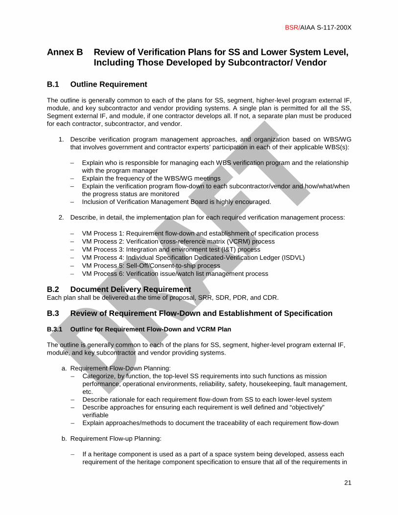
B.1 Outline Requirement The outline is generally common to each of the plans for SS, segment, higher-level program external IF, module, and key subcontractor and vendor providing systems. A single plan is permitted for all the SS, Segment external IF, and module, if one contractor develops all. If not, a separate plan must be produced for each contractor, subcontractor, and vendor.
1. Describe verification program management approaches, and organization based on WBS/WG that involves government and contractor experts’ participation in each of their applicable WBS(s):
– Explain who is responsible for managing each WBS verification program and the relationship
with the program manager – Explain the frequency of the WBS/WG meetings – Explain the verification program flow-down to each subcontractor/vendor and how/what/when
the progress status are monitored – Inclusion of Verification Management Board is highly encouraged.
2. Describe, in detail, the implementation plan for each required verification management process:
– VM Process 1: Requirement flow-down and establishment of specification process – VM Process 2: Verification cross-reference matrix (VCRM) process – VM Process 3: Integration and environment test (I&T) process – VM Process 4: Individual Specification Dedicated-Verification Ledger (ISDVL) – VM Process 5: Sell-Off/Consent-to-ship process – VM Process 6: Verification issue/watch list management process
B.2 Document Delivery Requirement Each plan shall be delivered at the time of proposal, SRR, SDR, PDR, and CDR.
B.3 Review of Requirement Flow-Down and Establishment of Specification B.3.1 Outline for Requirement Flow-Down and VCRM Plan The outline is generally common to each of the plans for SS, segment, higher-level program external IF, module, and key subcontractor and vendor providing systems.
a. Requirement Flow-Down Planning: – Categorize, by function, the top-level SS requirements into such functions as mission
performance, operational environments, reliability, safety, housekeeping, fault management, etc.
– Describe rationale for each requirement flow-down from SS to each lower-level system – Describe approaches for ensuring each requirement is well defined and “objectively”
verifiable – Explain approaches/methods to document the traceability of each requirement flow-down
b. Requirement Flow-up Planning:
– If a heritage component is used as a part of a space system being developed, assess each requirement of the heritage component specification to ensure that all of the requirements in

BSR/AIAA S-117-200X
22
the specification are compatible with upper level components/ top level system requirements by conducting requirement flow-up process and modify the heritage components if required.
– Describe rationale for the use of each requirement “as is” and “need for modification” c. VCRM:
– Explain the rationale for selecting the particular assigned verification method(s) for each requirement
B.3.2 Delivery Requirement Each plan shall be delivered at the time of SRR, SDR, PDR, and CDR. B.4 Analysis, Test, Inspection, and Demonstration Plan for SS and Lower Level
Systems (Based on VCRM Process) B.4.1 Outline for Verification by Analysis, Test, Inspection, and Demonstration Plan The outline is common to each of the plans for SS, segment, higher-level program external IF, element, subelement, subsystem, and unit including those developed by subcontractor and vendor providing systems.
a. List all the requirements (with requirement ID and brief description of the requirement) by each verification category, verify by analysis, test, inspection, and demonstration, for each specification
b. Explain scope and approaches to verify each category of the verification methods such that
they will ensure each requirement listed for each category will be properly verified c. Explain the Design Reference Case associated with each “Verify by Analysis” requirement d. Explain Test approaches/methods for each “Verify by Test” requirement e. Explain the rationale for “Verify by Similarity” for each applicable requirement such that none
of the constraints relating to its application to the system/program, software/hardware design, environments, safety, and life, etc. has changed from the earlier system
B.4.2 Delivery Requirement Each plan shall be delivered at the time of proposal, SRR, and SDR. The preliminary and final results of the Design & Analyses list must be presented at the corresponding PDR and CDR, respectively. It should be noted that these planning and the results become a critical part of PDR and CDR success criteria. B.5 I&T Plans for the SS and Lower Level Systems B.5.1 Outline for I&T Plan The outline is generally common to each of the plans for SS, and lower level systems including those built by subcontractor and vendor providing systems.
BSR/AIAA S-117-200X
23
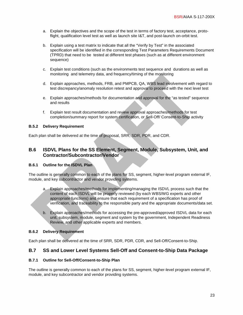
a. Explain the objectives and the scope of the test in terms of factory test, acceptance, proto-flight, qualification level test as well as launch site I&T, and post-launch on-orbit test.
b. Explain using a test matrix to indicate that all the “Verify by Test” in the associated
specification will be identified in the corresponding Test Parameters Requirements Document (TPRD) that need to be tested at different test phases (such as at different environment sequence)
c. Explain test conditions (such as the environments test sequence and durations as well as
monitoring and telemetry data, and frequency/timing of the monitoring d. Explain approaches, methods, FRB, and PMPCB, QA, WBS lead involvement with regard to
test discrepancy/anomaly resolution retest and approval to proceed with the next level test e. Explain approaches/methods for documentation and approval for the “as tested” sequence
and results f. Explain test result documentation and review approval approaches/methods for test
completion/summary report for system certification, or Sell-Off/ Consent-to-Ship activity B.5.2 Delivery Requirement Each plan shall be delivered at the time of proposal, SRR, SDR, PDR, and CDR.
B.6 ISDVL Plans for the SS Element, Segment, Module, Subsystem, Unit, and Contractor/Subcontractor/Vendor
B.6.1 Outline for the ISDVL Plan The outline is generally common to each of the plans for SS, segment, higher-level program external IF, module, and key subcontractor and vendor providing systems.
a. Explain approaches/methods for implementing/managing the ISDVL process such that the content of each ISDVL will be properly reviewed (by each WBS/WG experts and other appropriate functions) and ensure that each requirement of a specification has proof of verification, and traceability to the responsible party and the appropriate documents/data set.
b. Explain approaches/methods for accessing the pre-approved/approved ISDVL data for each
unit, subsystem, module, segment and system by the government, Independent Readiness Review, and other applicable experts and members.
B.6.2 Delivery Requirement Each plan shall be delivered at the time of SRR, SDR, PDR, CDR, and Sell-Off/Consent-to-Ship. B.7 SS and Lower Level Systems Sell-Off and Consent-to-Ship Data Package B.7.1 Outline for Sell-Off/Consent-to-Ship Plan The outline is generally common to each of the plans for SS, segment, higher-level program external IF, module, and key subcontractor and vendor providing systems.

BSR/AIAA S-117-200X
24
a. Describe approaches/methods for implementing/managing/approving the Sell-Off/Consent-to-Ship process
b. Explain entry/exit criteria for conducting successful Sell-Off/Consent-to-Ship for each system c. Describe Functional Configuration Audit (FCA) and Physical Configuration Audit (PCA) Plans d. Describe a standard sell-off/consent-to-ship data package that include ISDVL results, an “as-
tested” test report, test summary including environment test history, test anomaly and disposition summary, FRB/PMPCB summary (including approved/waived part lists), deviations/waivers summary, disposition status of action items generated at associated system’s CDR, TRR, and test data review, and disposition status of all the issue/concern items, FCA and PCA results associated with each SS
B.7.2 Delivery Requirement Each plan shall be delivered at the time of SRR, SDR, PDR, CDR, and Sell-Off/Consent-to-Ship. B.8 Verification Issue/Watch List Management Plan for SS, Segment, Higher
Level External IF, and Module B.8.1 Outline for Verification-Related Issue/Watch List Management Plan The outline is generally common to each of the plans for SS, segment, higher-level program external IF, module, and key subcontractor and vendor providing systems. It explains the WBS IPT/WG-based Issue/Watch List identification and resolution management approach, in which the WG experts identify and disposition verification related-risk items in a proactive and continuous manner to ensure that potential risks are identified and resolved in a timely manner to reduce the likelihood that late changes or post launch failures will occur. Issue/Watch List items may include those relating to verification of requirements, design/analysis, manufacturing, test, Sell-Off/Consent-to-Ship, and others as appropriate.
– Verification-related issues may include those that will impact cost, performance, and/or schedule, require consultation with an upper-level IPT/WG, and ultimately may become program-level risks if not resolved by the IPT/WG in a timely manner.
– Watch list (or concern) items are those that have either been judged to be low risk and do not
require a formal risk handling plan, or have not been included in a formal risk management process but could be included should their probability and/or consequence of occurrence increase sufficiently to exceed the minimum threshold established for evaluating candidate risks.
a. Explain the approaches/methods and Issue/Watch List documentation format for
capturing/tracking each item in terms of origination date, area/synopsis, responsibility/assignment, status, resolution approach, and approval authority/status.
b. Explain the approaches/methods for raising high risks and selected medium risks to the
upper-level WBS/WG and to the program-level risk management board as warranted. B.8.2 Delivery Requirement Each plan shall be delivered/reviewed at the time of SRR, SDR, PDR, CDR, and Sell-Off/Consent-to-Ship.
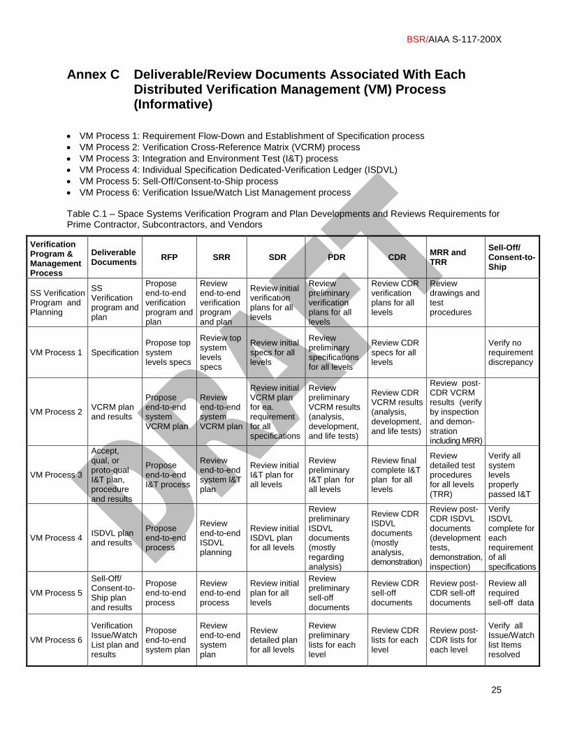
BSR/AIAA S-117-200X
25
Annex C Deliverable/Review Documents Associated With Each Distributed Verification Management (VM) Process (Informative)
• VM Process 1: Requirement Flow-Down and Establishment of Specification process • VM Process 2: Verification Cross-Reference Matrix (VCRM) process • VM Process 3: Integration and Environment Test (I&T) process • VM Process 4: Individual Specification Dedicated-Verification Ledger (ISDVL) • VM Process 5: Sell-Off/Consent-to-Ship process • VM Process 6: Verification Issue/Watch List Management process Table C.1 – Space Systems Verification Program and Plan Developments and Reviews Requirements for Prime Contractor, Subcontractors, and Vendors
Verification Program & Management Process
Deliverable Documents RFP SRR SDR PDR CDR MRR and
TRR
Sell-Off/ Consent-to-Ship
SS Verification Program and Planning
SS Verification program and plan
Propose end-to-end verification program and plan
Review end-to-end verification program and plan
Review initial verification plans for all levels
Review preliminary verification plans for all levels
Review CDR verification plans for all levels
Review drawings and test procedures
VM Process 1 Specification Propose top system levels specs
Review top system levels specs
Review initial specs for all levels
Review preliminary specifications for all levels
Review CDR specs for all levels
Verify no requirement discrepancy
VM Process 2 VCRM plan and results
Propose end-to-end system VCRM plan
Review end-to-end system VCRM plan
Review initial VCRM plan for ea. requirement for all specifications
Review preliminary VCRM results (analysis, development, and life tests)
Review CDR VCRM results (analysis, development, and life tests)
Review post-CDR VCRM results (verify by inspection and demon-stration including MRR)
VM Process 3
Accept, qual, or proto-qual I&T plan, procedure and results
Propose end-to-end I&T process
Review end-to-end system l&T plan
Review initial I&T plan for all levels
Review preliminary I&T plan for all levels
Review final complete I&T plan for all levels
Review detailed test procedures for all levels (TRR)
Verify all system levels properly passed I&T
VM Process 4 ISDVL plan and results
Propose end-to-end process
Review end-to-end ISDVL planning
Review initial ISDVL plan for all levels
Review preliminary ISDVL documents (mostly regarding analysis)
Review CDR ISDVL documents (mostly analysis, demonstration)
Review post-CDR ISDVL documents (development tests, demonstration, inspection)
Verify ISDVL complete for each requirement of all specifications
VM Process 5
Sell-Off/ Consent-to-Ship plan and results
Propose end-to-end process
Review end-to-end process
Review initial plan for all levels
Review preliminary sell-off documents
Review CDR sell-off documents
Review post-CDR sell-off documents
Review all required sell-off data
VM Process 6
Verification Issue/Watch List plan and results
Propose end-to-end system plan
Review end-to-end system plan
Review detailed plan for all levels
Review preliminary lists for each level
Review CDR lists for each level
Review post-CDR lists for each level
Verify all Issue/Watch list Items resolved
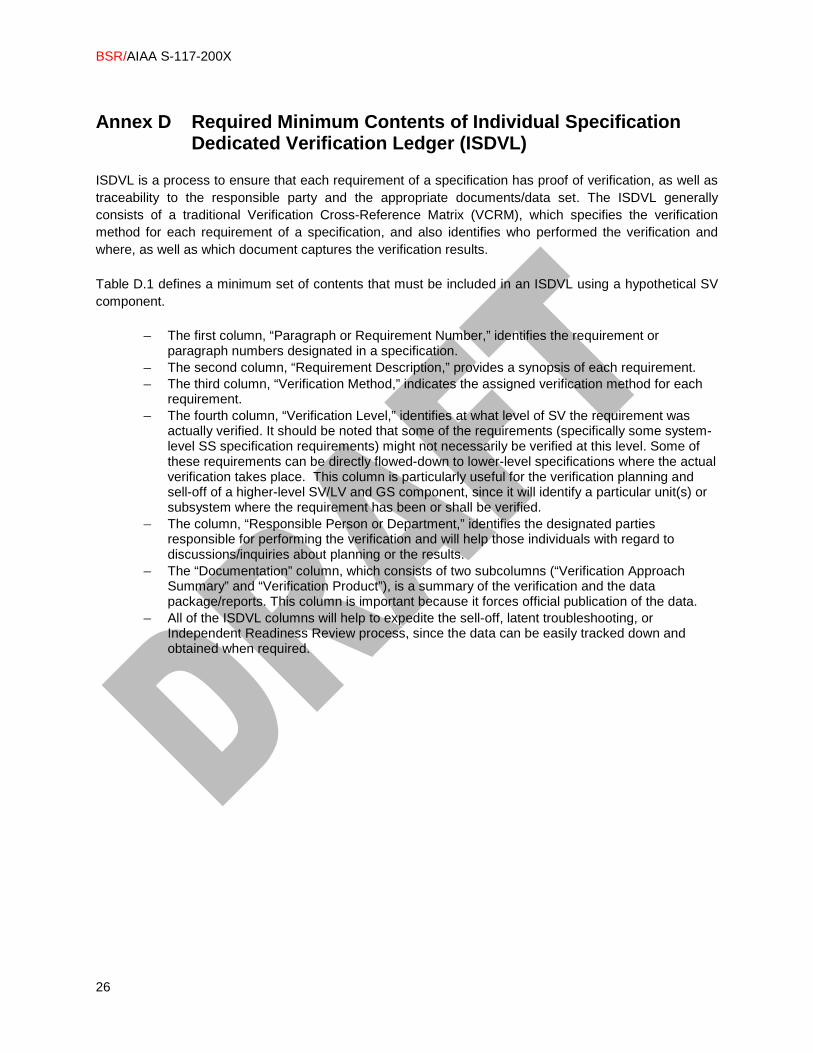
BSR/AIAA S-117-200X
26
Annex D Required Minimum Contents of Individual Specification
Dedicated Verification Ledger (ISDVL) ISDVL is a process to ensure that each requirement of a specification has proof of verification, as well as traceability to the responsible party and the appropriate documents/data set. The ISDVL generally consists of a traditional Verification Cross-Reference Matrix (VCRM), which specifies the verification method for each requirement of a specification, and also identifies who performed the verification and where, as well as which document captures the verification results. Table D.1 defines a minimum set of contents that must be included in an ISDVL using a hypothetical SV component.
– The first column, “Paragraph or Requirement Number,” identifies the requirement or paragraph numbers designated in a specification.
– The second column, “Requirement Description,” provides a synopsis of each requirement. – The third column, “Verification Method,” indicates the assigned verification method for each
requirement. – The fourth column, “Verification Level,” identifies at what level of SV the requirement was
actually verified. It should be noted that some of the requirements (specifically some system-level SS specification requirements) might not necessarily be verified at this level. Some of these requirements can be directly flowed-down to lower-level specifications where the actual verification takes place. This column is particularly useful for the verification planning and sell-off of a higher-level SV/LV and GS component, since it will identify a particular unit(s) or subsystem where the requirement has been or shall be verified.
– The column, “Responsible Person or Department,” identifies the designated parties responsible for performing the verification and will help those individuals with regard to discussions/inquiries about planning or the results.
– The “Documentation” column, which consists of two subcolumns (“Verification Approach Summary” and “Verification Product”), is a summary of the verification and the data package/reports. This column is important because it forces official publication of the data.
– All of the ISDVL columns will help to expedite the sell-off, latent troubleshooting, or Independent Readiness Review process, since the data can be easily tracked down and obtained when required.
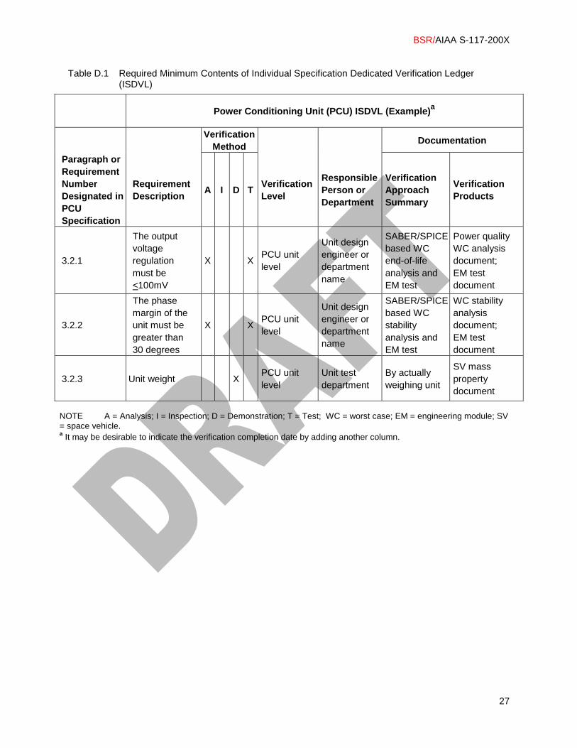
BSR/AIAA S-117-200X
27
Table D.1 Required Minimum Contents of Individual Specification Dedicated Verification Ledger (ISDVL)
NOTE A = Analysis; I = Inspection; D = Demonstration; T = Test; WC = worst case; EM = engineering module; SV = space vehicle. a It may be desirable to indicate the verification completion date by adding another column.
Power Conditioning Unit (PCU) ISDVL (Example)a
Verification Method Documentation
Paragraph or Requirement Number Designated in PCU Specification
Requirement Description A I D T Verification
Level
Responsible Person or Department
Verification Approach Summary
Verification Products
3.2.1
The output voltage regulation must be <100mV
X X PCU unit level
Unit design engineer or department name
SABER/SPICE based WC end-of-life analysis and EM test
Power quality WC analysis document; EM test document
3.2.2
The phase margin of the unit must be greater than 30 degrees
X X PCU unit level
Unit design engineer or department name
SABER/SPICE based WC stability analysis and EM test
WC stability analysis document; EM test document
3.2.3 Unit weight X PCU unit level
Unit test department
By actually weighing unit
SV mass property document
BSR/AIAA S-117-200X
28
Annex E Check List for Planning and Executing Late Changes, Heritage, or Commercial System Applications (Informative)
E.1 Scope It is important that one plans and executes thorough verification for any late changes, heritage, or commercial system applications for not only the affected part of the system being developed but also other collateral systems including the lower and upper level systems. A checklist for planning and execution process for each late change, heritage, or commercial system category is explained, mostly based on the actual past post-launch failure experiences, in the following sections. E.2 Checklist for Planning and Executing Late Changes, Heritage, or
Commercial System Applications: Requirement/CONOPS Related 1. Are the rationales for the requirement change, heritage, or commercial requirement clearly defined? 2. Is each of the requirement changes, heritage, or commercial requirements properly approved by a
requirement change board avoiding ad-hoc change? 3. Is the requirement change, heritage, or commercial requirements properly communicated to and
understood by all the internal and external parties, affected by the change? 4. Are the requirement changes, heritage, or commercial systems requirements clearly written,
specified, and verifiable? 5. Are the design reference cases (i.e., reasonable worst-case conditions) specified for late changes,
heritage, or commercial systems? 6. Is (measurement) unit tolerance specified? In particular, impacts of any requirement changes must
be closely examined for such areas as (a) critical clearances, (b) subsystem-to-subsystem interfaces (IFs), and (c) HW/SW IFs.
7. Is the requirement written with one requirement ID per requirement? 8. Are the requirement changes or heritage requirements properly specified for both primary and
redundant configuration? 9. Are all the requirement verification methods and/or approaches properly delineated? 10. Does the requirement change, heritage, or commercial system requirements impact other
requirements and associated verification methods in the same related specification? 11. Do the requirement changes or heritage systems requirements impact the flowed-up and flow-
downed requirements and the associated verification methods in other specifications such as those for assembly, unit, subsystem, etc) requirements and associated verification methods?
12. Do the requirement changes or heritage system requirements impact both HW and SW requirements? If so, compatibility of both HW and SW analyzed and tested after requirement changes?
E.3 Checklist for Planning and Executing Late Changes, Heritage, or
Commercial System Applications: Design and Analysis Related 1. Are the rationales for the design change clearly defined? 2. Do the design changes or heritage designs (HW/SW) analyzed/tested for the appropriate applications
and operating conditions? 3. Are the designs changes due to anomaly, or the use of heritage (or commercial) systems to correct
problems are done based on a clear understanding of the problem, such as test anomaly and root cause assessments?
4. Are the design changes, heritage, or commercial designs impact approved by design change board avoiding ad-hoc change?
5. Are the design changes, heritage, or commercial designs (HW/SW) under configuration control? 6. Do the design changes, heritage, or commercial designs impact the other designs within the same
HW/SW system? If so, compatibility of both HW and SW analyzed?

BSR/AIAA S-117-200X
29
7. Are the memory and throughput margins adequate after the SW changes and heritage designs implementations?
8. Are the design changes or heritage flight SW tested with high-fidelity hardware-in-the-loop using the flight test configuration?
9. Do the design changes or heritage designs impact other systems (module, unit, subsystem, etc.) and related interface designs?
10. Do the design changes, heritage, or commercial designs impact any requirements? If so, is a requirement change checklist listed in E.2 (1) through (12) used?
11. Are the design changes, heritage, or commercial designs clearly verified by the appropriate set of worst-case analyses including the thermal, mechanical, EMC/EMI and radiation environments, turn on, turn-off, and steady state mode?
12. Are the design changes, heritage, or commercial designs properly specified for both primary and redundant configuration?
13. Are the design changes, heritage, or commercial designs analyzed for FMEA, propagated failure analysis, and sneak circuit analysis instead of depending on previous analyses?
14. Do the design changes or heritage designs (HW/SW) impact the fault management architecture? If so, make sure that the change does not cause computer lock-up, endless-loop operation, or create a problem of a space vehicle unable to settle in safe mode in case of failure.
15. Are the design changes, heritage, or commercial designs’ with their piece parts and materials characteristics verified to satisfy performance and reliability requirements?
E.4 Checklist for Planning and Executing Late Changes, Heritage, or
Commercial System Applications: Manufacturing Related 1. Are the rationales for the manufacturing changes, the use of heritage, or manufacturing procedures
clearly defined? 2. Do the manufacturing changes, heritage, or commercial systems manufacturing procedures specify
tolerance such as for torque for bolts or nuts, spacing, wire separation, etc.? 3. Is the manufacturing change, heritage, or commercial systems manufacturing procedures properly
approved by configuration management, material review board? 4. Are the manufacturing changes, heritage, or commercial systems manufacturing procedures
properly communicated to and understood by all the internal and/or external parties impacted by the change? (This is to avoid latent problems such as those relating to critical clearances, electrical ground changes, sneak path, EMC/EMI, or single-point failures).
5. Do the manufacturing changes, heritage, or commercial systems manufacturing procedures disturb the EMC/EMI shield? If so, make sure that EMC/EMI leaks are tested after the change and repairs.
6. Do the manufacturing changes, heritage, or commercial systems manufacturing procedures relating to electrical wiring include rerouting and/or addition of wires or piece parts? If so, make sure that it did not create a sneak path or ground path change.
7. Are the manufacturing changes, heritage, or commercial systems manufacturing procedures properly specified for both primary and redundant configuration?
8. Are the manufacturing changes, heritage, or commercial systems manufacturing procedures clearly written and specified, and each step of the change procedure verifiable by an independent inspector, such as QA personnel? In particular, unambiguous inspection points and criteria should be developed.
9. Are the manufacturing changes, heritage, or commercial systems manufacturing procedures involving soft materials such as cable and multilayer insulation? If so, ensure that they cannot move unexpectedly in the launch or space environment and cause interference.
10. Do the manufacturing changes, heritage, or commercial systems manufacturing procedures involve structures that can snag soft items? If so, ensure to route wires to avoid pinching or snagging by a deployed structure.
11. Do the manufacturing changes, heritage, or commercial systems manufacturing procedures involve deployable mechanisms? If so, make sure that the deployable arms and shoulder are not obstructed by other structures such as thermal blankets or wires, etc.

BSR/AIAA S-117-200X
30
E.5 Checklist for Planning and Executing Late Changes, Heritage, or Commercial System Applications: System Integration and Test Related
1. Are the rationales for test changes, heritage, or commercial system tests clearly defined? 2. Are the late changes, heritage, or commercial systems tests properly communicated to and
understood by all the internal and external parties impacted by these changes or new applications? 3. Are the test/retest plan/procedures for late changes, heritage, or commercial systems properly
written such that all the “verify by test” requirements will be properly tested under the required test condition and/or configurations including those relating to critical clearances, subsystem-to-subsystem IFs, HW/SW IFs, etc.
4. Do the late change, heritage, or commercial systems need to be verified by other verification methods including tested under test like you fly (TLYF)?
5. Is the extent and type of retest (penalty test) after anomaly troubleshooting and resolution properly approved by internal and external experts? In particular, is the retest plan written based on clear understanding of the test anomaly and its root cause?
6. Are the late changes, heritage, or commercial systems properly tested for all applicable space-vehicle operating modes such as cold start, turn-on turn-off sequence, eclipse, deployment separation, etc.?
7. Is the test equipment properly calibrated and maintained? 8. Are the reuses of heritage, or commercial test equipment or test configuration properly validated
before testing, so that it will not damage or erroneously test flight articles? In particular, do the heritage or commercial test equipment and its configuration provide some electrical sneak paths such as for flight article’s grounding, signal, or power path?
9. Are the tests planned such that it will help review for trends, oddities, “out-of-family” values, and other indicators of anomalies?
10. Is the test procedure written such that flight article responses will be characterized in trial runs with limited force, current, or temperature before going into full tests?
11. Do the tests plans include the inspection of flight articles after testing particularly after vibration, acoustic tests, thermal cycling, or live pyrotechnic firing?
12. Is the heritage or commercial test equipment qualified such that it will not contaminate the flight article latter if it resides with flight article in T/V or T/C chamber?
E.6 Checklist for Planning and Executing Late Changes, Heritage, or
Commercial System Applications: Piece Parts and Materials Related 1. Are the rationales for the use of heritage or commercial piece parts and materials, or changes due to
alerts clearly defined? 2. Are the heritage or commercial piece parts and materials, or changes due to alerts approved by an
appropriate change board and internal and external experts? 3. Are the heritage or commercial piece parts and materials, or changes due to an alert properly
analyzed and/or tested for the actual flight applications? 4. Do the heritage or commercial piece parts and materials, or changes due to an alert impact
requirements, design, manufacturing, and test? If so, make sure to follow the checklist specified in E.2 through E.5.