Thermodynamic Vent System Test in a Low Earth Orbit Simulation

100 Engenharia Térmica (Thermal Engineering), Vol. 3 · No. 2 · December 2004 · p. 100-106
SPACE SIMULATION OF THE CHINA-BRAZIL EARTHRESOURCES SATELLITE – CBERS
E. C. Garciaa,M. B. dos Santosb*,J. S. de Almeidac*,and D. L. Panissid*
aEng. Mecânica-Aeronáutica – ITA
12228-900 - São José dos Campos - SP Brasil
[email protected]@lit.inpe.br
*Laboratório de Integração e Testes – INPE
Avenida dos Astronautas, 1758
12227-010 - São José dos Campos – SP
Brasil
Fax (55) 12 3941-1884
ABSTRACT
Space Simulation Tests are performed in spacecraft in order to verify equipment properoperation under thermal vacuum conditioning and to verify the correct workmanship inthe assembling of the flight spacecraft as a whole. This paper presents the space simulation(thermal vacuum test) developed in the China Brazil Earth Resources Satellite, FlightModel no. 2, that took place at the Integration and Tests Laboratory – LIT, INPE. Measuringapproximately 1.8 x 2.0 x 2.2m, weighting 1,500 kg and carrying three cameras as themain payload, this spacecraft is scheduled to be launched in China. The spacecraft wasinstalled in the 3x3m space simulation chamber and the tests run 24 hours a day completinga total of 350 hours. Using the technique of skin-heaters complemented by the thermalvacuum chamber thermally conditioned shrouds and cold plates, dedicated heat inputsand heat sink where applied at the spacecraft surfaces in order to obtain the required highand low acceptance values of temperature and, subsequently, simulating the operationalconditions for the necessary electronic subsystems functioning tests of the spacecraft.This test campaign included teams from both China and Brazil, summing a total of 67people directly involved.
Keywords: Space Simulation, Satellite, Thermal Control, CBERS, Thermal Vacuum
INTRODUCTION
This paper details the approach adopted andapplied in the Space Simulation (SS) campaign ofthe China Brazil Earth Resources Satellite, FlightModel #2, (CBERS-FM2), successfully performedat the Integration and Tests Laboratory – LIT,National Institute for Space Research – INPE, inSão José dos Campos, SP, from September 7th to28th, 2001. Measuring approximately 1.8 x 2.0 x2.2m, weighting 1,500 kg and carrying threecameras as the main payload, this spacecraft (S/C)is scheduled to be launched in China and it will beorbiting the Earth at 778km as part of its remotesensing mission profile as represented by Fig. 1.
Satellites are subjected to extensive groundthermal testing to verify its thermal design andensure successful operational use in flight. TheMIL-STD-1540B (1982) standardizes the testrequirements and establishes a uniform set ofdefinitions, environmental criteria, and testmethods for military space vehicles, subsystemsand components.
The test environment was built to simulatethe various environmental stresses to which thesatellite was designed. The thermal stresses adoptedin the design were related to equipment operation,internal heating, eclipse conditions, space-vehicle
orientation, environmental heating (including solar,earthshine infrared and albedo radiation), ascentheating, and degradation of thermal surfaces duringthe mission lifetime. These stress conditions areused in the analytical modeling in order to predict,over the operational lifetime of the spacecraft, theworst-case hot and cold temperatures for thecomponent, subsystem and for the satellite. Fromthese results, acceptance and qualificationtemperatures are derived (Gilmore, 1994).
Figure 1. CBERS-FM2 Satellite Mission.

101Engenharia Térmica (Thermal Engineering), Vol. 3 · No. 2 · December 2004 · p. 100-106
E. C. Garcia et al. Space Simulation of The...
The primary purpose of the spacesimulation (or thermal vacuum test) is to verifythe functional performance of the satellite.Without the convective heat transferenvironment, the temperature and stressesclosely simulate the on-flight conditions.Following the requirements from MIL-STD-1540B (1982), a minimum of four cycles arerequired at the acceptance level, where eachcycle is then composed by both the maximumand minimum predicted temperatures.
Exploring the capabilities of the 3m x 3mThermal Vacuum (T/V) Chamber from LIT–INPE in terms of appropriately selecting andadjusting its cold shroud temperatures (heat sink)and also some low cost heat input/sinktechniques, the CBERS-FM2 spacecraft wasadequately disjoined at its service and payloadmodel interface in such a way that each sectioncould physically fit inside the T/V Chamber oneat a time. Assuring all the necessary functionaland test cabling interconnection between the twomodels through the chamber walls for the properspacecraft electrical operations as an integratedsystem, specific thermal test techniques wereapplied in order to obtain the required hot andcold acceptance levels of temperature at thespacecraft subsystems and structural surfaces, asa consequence of the simulated thermalconditioning from the distinct orbitalconfigurations. These thermal simulationtechniques consisted of a combination of skin-heaters, the thermal vacuum chamber mainshrouds (operating as heat sinks) and dedicatedLiquid Nitrogen (LN2) cold plate, effectivelyleading to reliable and very satisfactory testingmethodology results.
Taking more than 350 hours and having67 people directly involved, including teamsfrom both INPE and CAST (Chinese Academyof Space Technology), this test can be consideredas a very important accomplishment in terms ofdistinct technique of spacecraft testing and alsoin terms of the satisfactory working relationshipbetween two quite different cultures as theBrazilian and the Chinese.
In this paper the satellite subsystems willbe referred by their codes as stated in theCBERS program. Weiqun and Carleial (1992)describe the correlation of each equipmentcode.
CBERS-FM2 SPACE SIMULATIONREQUIREMENTS
The execution of the CBERS-FM2 spacesimulation tests complied with the maximum andminimum temperatures defined for acceptancelevel, as described in the CBERS EnvironmentalSpecification (Zhixu et al., 1996). This documentalso presents the main operating temperatures forequipment in acceptance level. The T/V Chamberpressure was required to be less than 1.33x10⁻³ Pa.
SIMULATION OUTLINE
Basically, the CBERS FM2 Space Simulationconsisted in cycling the satellite equipment to two(hot and cold) temperature soaks in a vacuumenvironment, while functional tests were performedin each soak. According to Zhixu et al. (1996), thesatellite had to remain at each temperature soakfor 8 hours. The time duration at the temperaturesoak had to be sufficient to test orbital operationalconditions and all the equipment functional modes.Four cycles were performed. This procedure wouldallow the possibility of equipment failures due tofabrication or handling procedures to be identified.In Fig. 2, one cycle of the SS is illustrated.
Figure 2. Space Simulation Temperature Cycle.
In the SS of CBERS-FM2, the satellite wassubmitted to functional tests in each temperaturesoak, while in transition from one temperature soakto the next one, it was kept most of the time instandby mode.
Due to the limited size of LIT’s thermalvacuum chamber, the SS of CBERS-FM2 wasconducted in two phases. The Service Module (SM)had to be separated from the Payload Module (PM),
102
E. C. Garcia et al. Space Simulation of The...
so that each module could be put inside of the T/Vchamber and tested one at a time.
The following test philosophy was adopted:• Test hot soaks: impose +5 ~ +10oC above
the predicted hot case flight temperatures in eachsatellite module to obtain the simulation predictedtemperatures.
• Test cold soaks: impose -5 ~ -10oC belowof the predicted cold case flight temperatures ineach satellite module to obtain the simulationpredicted temperatures.
• Assure that the temperatures of the modulesremain between the simulation predictedtemperatures and the acceptance levels.
• First the Service Module was tested,followed by the Payload Module.
• The Solar Array Generator (solar panel) wasnot integrated in the spacecraft during the SS. TheBAPTA motor was checked for its correct operation.
• The majority of the antennas were removedfrom SM and PM. The SS was performed usingRF cables only.
The SS electrical cabling (high and lowfrequency) was designed and built by the LIT team.Garcia (2001) presents the cabling configurationsin the thermal vacuum procedures for SM and PMsimulations. Garcia (2001) also presents thePredicted Flight Temperatures for Flight and forSpace Simulation of CBERS-FM2, for the hot andcold cases. In the same way, Garcia (2001) alsoshows a correlation between nodes from themathematical model and equipment codes.
SERVICE MODULE OF CBERS-FM2SATELLITE
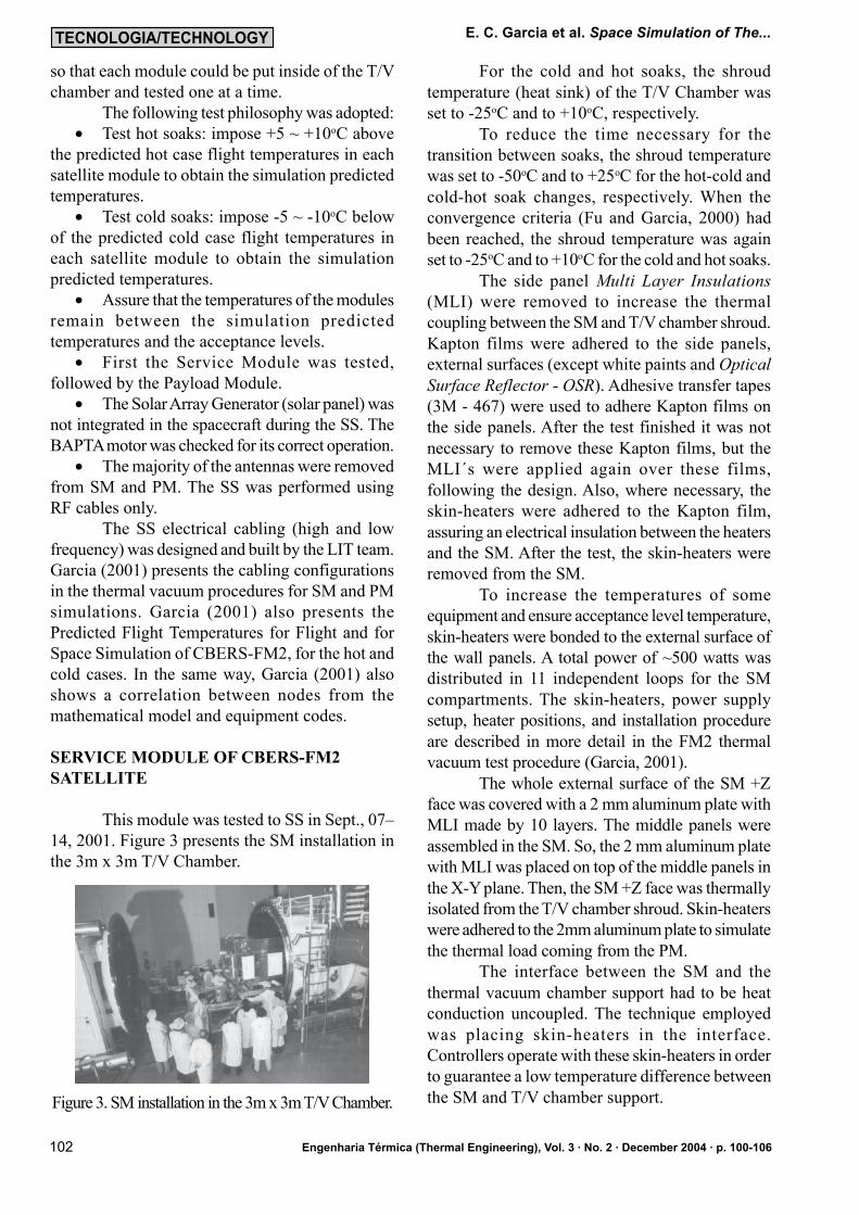
This module was tested to SS in Sept., 07–14, 2001. Figure 3 presents the SM installation inthe 3m x 3m T/V Chamber.
Figure 3. SM installation in the 3m x 3m T/V Chamber.
For the cold and hot soaks, the shroudtemperature (heat sink) of the T/V Chamber wasset to -25oC and to +10oC, respectively.
To reduce the time necessary for thetransition between soaks, the shroud temperaturewas set to -50oC and to +25oC for the hot-cold andcold-hot soak changes, respectively. When theconvergence criteria (Fu and Garcia, 2000) hadbeen reached, the shroud temperature was againset to -25oC and to +10oC for the cold and hot soaks.
The side panel Multi Layer Insulations(MLI) were removed to increase the thermalcoupling between the SM and T/V chamber shroud.Kapton films were adhered to the side panels,external surfaces (except white paints and OpticalSurface Reflector - OSR). Adhesive transfer tapes(3M - 467) were used to adhere Kapton films onthe side panels. After the test finished it was notnecessary to remove these Kapton films, but theMLI´s were applied again over these films,following the design. Also, where necessary, theskin-heaters were adhered to the Kapton film,assuring an electrical insulation between the heatersand the SM. After the test, the skin-heaters wereremoved from the SM.
To increase the temperatures of someequipment and ensure acceptance level temperature,skin-heaters were bonded to the external surface ofthe wall panels. A total power of ~500 watts wasdistributed in 11 independent loops for the SMcompartments. The skin-heaters, power supplysetup, heater positions, and installation procedureare described in more detail in the FM2 thermalvacuum test procedure (Garcia, 2001).
The whole external surface of the SM +Zface was covered with a 2 mm aluminum plate withMLI made by 10 layers. The middle panels wereassembled in the SM. So, the 2 mm aluminum platewith MLI was placed on top of the middle panels inthe Z-Y plane. Then, the SM +Z face was thermallyisolated from the T/V chamber shroud. Skin-heaterswere adhered to the 2mm aluminum plate to simulatethe thermal load coming from the PM.
The interface between the SM and thethermal vacuum chamber support had to be heatconduction uncoupled. The technique employedwas placing skin-heaters in the interface.Controllers operate with these skin-heaters in orderto guarantee a low temperature difference betweenthe SM and T/V chamber support.
Engenharia Térmica (Thermal Engineering), Vol. 3 · No. 2 · December 2004 · p. 100-106

103
A cold plate filled with liquid nitrogen waspositioned next to the Battery panel. So, the Batterypanel was thermally coupled only with a cryogenicsurface (temperature around -180oC). This LN2plate had a 15 layers MLI on its external face andpresented an emissivity higher than 0.8 on itsinternal surface. This setup is presented in Fig. 4.
Figure 4. This picture presents the support, theLiquid Nitrogen Plate positioned on Battery Panel(at the center of the SM, silver color) and ThermalVacuum Chamber.
The propulsion system was pressurizedwith nitrogen gas (GN2) (purity > 99.995 %) at1.7 MPa.
The CBERS-FM2 Batteries were used forthe SS (not an Engineering Model Product).
The equipment of SM was monitored by33 thermistors plus 21 thermocouples (a total of54). Also, 28 additional thermocouples were usedto verify the temperature of the SM panels, theinterface between SM and support, and the LN2cold plate.
The beginning of both hot and coldtemperature soaks for the SM was considered tohad been reached when all equipment matched thepredicted temperatures (Garcia, 2001) within amargin of ±2.5oC.
The time to perform one cycle for the SMT/V test was 40 hours. Thus, the SM T/V testduration was about 7 days.
Figures 5 and 6 present in sequence thetemperature profiles (cycles) developed in someSM compartments.
Figure 5. Temperature profile in the equipmentCBC4, CBCH, CBCE-B, CBC3 and CBCG, whichare located inside of the SM2 compartment.
Figure 6. Temperature Profiles in the propulsionsystem (equip. CBCO, CBBA, CBMB) which arelocated inside the SM9 compartment.
Test anomalies
Two main anomalies were identified, asfollowing:
• The white paint of the sidewall panel +Z(heat rejection area) was unbounded during the SS.It was verified just after opening the T/V chamberdoor. Figure 7 presents a picture of this panel withpart of the paint that was unbounded inside of theT/V Chamber.
• The RIGA equipment (Chinese) and SEMpresented mal-functioning during the SS. TheCAST team had the responsibility of identifyingthe problems and to present solutions.
PAYLOAD MODULE TEST OF THECBERS-FM2 SATELLITE
The Payload Module (PM) Test wasperformed from September 20 – 28, 2001.
For the PM cold and hot soaks, the shroudtemperature was set to -15oC and to +20oC,respectively. Also, to decrease the time necessaryfor the transition between soaks, the shroudtemperature was set to -20oC and to +35oC for thehot-cold and cold-hot soak changes, respectively.When the convergence criteria was obtained, theshroud temperature was again set to -15oC and to
E. C. Garcia et al. Space Simulation of The...
Engenharia Térmica (Thermal Engineering), Vol. 3 · No. 2 · December 2004 · p. 100-106

104
+20oC for the cold and hot soaks, respectively. Also,the time to perform one cycle for the PM spacesimulation was 40 hours. Thus, the SS duration forthe PM test was 7 days.
Figure 8 presents the PM installation insidethe 3m x 3m T/V Chamber.
Figure 7. Heat rejection area (white paint)unbounded off the +Z sidewall SM panel.
Figure 8. Top: PM installation in the 3m x 3m T/Vhamber. Bottom: view of the complete setup,including the SM positioned outside the T/V.
The PM roof panel was covered with MLI,as designed for flight. All side panel MLI´s were
removed to increase the thermal coupling betweenthe PM and T/V chamber shroud. Again, Kaptonfilms were adhered to the side panels, externalsurfaces (except for white paints and OSRsurfaces). Also, to increase the temperatures ofsome equipment and ensure acceptance leveltemperature, skin-heaters were bonded to theexternal surface of the wall panels. These can beseen in Figs. 8 and 9. A total power of 400 wattswas distributed in 10 independent loops for the PMcompartments. The power in each compartmentwas uniformly distributed on its wall panel. Theskin-heaters, power supply setup, heater positionsand installation procedure are described in moredetail in the FM2 Thermal Vacuum Test procedure(Garcia, 2001).
The interface between the PM and thethermal vacuum chamber support had to be heatconduction uncoupled as well. The techniqueemployed was placing skin-heaters at the interface.Controllers operated these skin-heaters to guaranteea minimum temperature difference between the PMand T/V chamber support.
The flight CBERS-FM2 Infrared MultiSpectral Scanner (IRMSS) was replaced by theengineering model (EM) camera in the followingconfiguration:
• The scanner mainframe was the EMproduct;
• The amplifier, encoder and radiative coolercontroller were CBERS-FM2 products;
• The CBERS-FM2 Flight CCD camera wasused for the T/V test.
A LN2 Cold Plate was positioned near the
PM bottom section to remove possiblecontamination from the satellite. This plateoperated as a trap and a significant quantity ofcontamination was removed from PM. Also, twelvewitness plates were installed on T/V Chamber wallsand PM surfaces to detect any contaminationproblems. As a result, high levels of esters andmethyl-silicone contamination were detected on asensor installed next to the T/V chamberdecontamination plate. After the test, thecontamination, which had been moved from thesatellite to LN2 cold plate, had dropped on T/Vchamber shroud. Also, wipe tests (collect ofmaterial after the test) were raised from T/Vchamber and PM surfaces. In these situations highlevels of esters and methyl-silicone were detectedat the center of the shroud and next to LN2 plate.
E. C. Garcia et al. Space Simulation of The...
Engenharia Térmica (Thermal Engineering), Vol. 3 · No. 2 · December 2004 · p. 100-106

105
In addition, high levels of methyl-phenyl-siliconewere detected on IR/DT Converter Equipmentsurface and on CCD Camera (internal surface).
The PM equipment was monitored by 30thermistors plus 31 thermocouples (a total of 61).Also, additional 36 thermocouples were used toverify the temperature of the PM panels, interfacebetween PM and support, and LN2 plate. The startpoint of both hot and cold temperature soaks forthe PM was considered to had been reached whenall equipment had matched the predictedtemperatures (Garcia, 2001) within a margin of±2.5oC. Figures 10 and 11 present the temperatureprofiles (cycles) developed in some of the PMcompartments.
Test anomalies
An anomaly was verified during PM spacesimulation: the equipment RTU-4 presented a mal-function behavior. INPE‘s team had theresponsibility of identifying the problem and topresent solutions.
PERSONNEL DIRECTLY INVOLVED
The teams and quantity of people involvedduring the SS of SM and PM is related as following:
• Thermal Vacuum (LIT): 12• S/C Integration & Electrical (LIT): 06• T/V Data Acquisition (LIT): 03• Lab. Maintenance (LIT): 04• INPE Thermal Design: 01• INPE Product Assurance: 01• CAST: 40
Figure 9. PM installed inside the T/V Chamber.View of the electrical interface cabling to SM,which was positioned outside the T/V Chamber.
Figure 10. Temperature profiles developed in theequipment CBJL-A, CBJI and CBJN. (PM2compartment).
Figure 11. Temperature profiles developed in theequipment CBIC, CBKA, CBKE and CBID. (PM5compartment).
CONCLUSIONS
The test results show that the mainobjectives of achieving high vacuum condition andequipment temperature between the minimum (forthe hot cases) and maximum (for the cold cases)of the predicted acceptance level temperatures weresuccessfully satisfied. Tables 1 and 2 present thequantity of equipment for SM and PM, respectively,that had their temperature values inside thetemperature convergence range (in terms ofpercentages).
In 1998, the first satellite from theBrazilian-Chinese cooperation (CBERS-FM1) wastested in Beijing. The FM1 test technique used inBeijing was to keep the T/V chamber shroud atLN2 temperature (-196°C). The thermal loads wereimposed by skin-heaters plus the installation ofelectrical strips (operating in the infrared radiationspectrum), near some areas of the satellite, as CCD,IRMSS and WFI cameras. Also, the satellite wasnot separated in two modules. The PM wasmechanically coupled with the SM and both wereput inside the 12m x 7m Chinese T/V Chamber.So, the Brazilian technique used for the FM2 testingwas pretty different from the Chinese. Tables 3 and
E. C. Garcia et al. Space Simulation of The...
Engenharia Térmica (Thermal Engineering), Vol. 3 · No. 2 · December 2004 · p. 100-106

106
Table 3. FM1 versus FM2 ConvergencePerformance Analysis during Hot Cases.
Table 4. FM1 versus FM2 ConvergencePerformance Analysis during Cold Cases.
REFERENCES
Fu, P. Z. and Garcia, E. C, 2000,Specification for CBERS FM2 Thermal VacuumTest, Private Communication, INPE, doc. c-hds-0022, São José dos Campos, Brazil, 39p.
Garcia, E. C., 2001, SM Thermo VacuumTest Thermal Control Procedure , PrivateCommunication, INPE, doc. lit01-cbers-tp-027,São José dos Campos, 34p.
Garcia, E. C., 2001, PM Thermo VacuumTest Thermal Control Procedure , PrivateCommunication, INPE, doc. lit01-cbers-tp-028,São José dos Campos, 31p.
Gilmore, D. G., 1994, Satellite ThermalControl Handbook, The Aerospace CorporationPress, chapter ix, El Segundo, California, pp. 9.3-9.35.
MIL-STD-1540B (USAF), 1982, TestRequirements for Space Vehicles , MilitaryStandard.
Weiqun, S. and Carleial, A. B., 1992,CBERS Satellite Product Matrix, PrivateCommunication, CAST-INPE, doc. cb-mng-010,São José dos Campos, 10p.
Zhixu, S., Wenming, Z., Bueno, L. A. R.and Stephany, S., 1996, EnvironmentalSpecification, Private Communication, INPE, doc.Cb-evs-001, São José dos Campos, 34p.
4 present an analysis of the results obtainedf rom the FM1 ( fu l f i l l ed by Chinesetechnique) and the FM2 ( fu l f i l l ed byBrazilian technique).
The main conclusions of the CBERS-FM2 Space Simulation are:
• Thermal vacuum chamber run 350hours with no problems (very smooth test);
• Data acquisition run fine, without datalost;
• Skin-heaters technique proved to bereliable;
• Temperature convergence criteria wellsatisfied
• 67 people directly involved with goodrelationship and cooperation between Chineseand Brazilian teams;
• SS of FM2 (accomplished in Brazil)had better performance than FM1 satellite(accomplished in China);
• CBERS FM2 Space S imula t ionper formed a t LIT/ INPE wi th comple tesuccess.
ACNOWLEDGEMENTS
The authors are thankfull to CNPq forthe financial support.
Table 1. Quantity of SM equipment inside of thetest convergence range.
Table 2. Quantity of PM equipment inside of thetest convergence range.
E. C. Garcia et al. Space Simulation of The...
Engenharia Térmica (Thermal Engineering), Vol. 3 · No. 2 · December 2004 · p. 100-106