Space Shuttle Data Processing System. Digital Processing System - General The Orbiter functions and...
49
Space Shuttle Data Processing System
-
Upload
amber-lynch -
Category
Documents
-
view
216 -
download
0
Transcript of Space Shuttle Data Processing System. Digital Processing System - General The Orbiter functions and...
Space Shuttle Data Processing
System
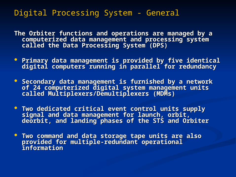
Digital Processing System - GeneralDigital Processing System - General
The Orbiter functions and operations are managed by a The Orbiter functions and operations are managed by a computerized data management and processing system computerized data management and processing system called the Data Processing System (DPS)called the Data Processing System (DPS)
Primary data management is provided by five identical Primary data management is provided by five identical digital computers running in parallel for redundancydigital computers running in parallel for redundancy
Secondary data management is furnished by a network of Secondary data management is furnished by a network of 24 computerized digital system management units called 24 computerized digital system management units called Multiplexers/Demultiplexers (MDMs)Multiplexers/Demultiplexers (MDMs)
Two dedicated critical event control units supply signal Two dedicated critical event control units supply signal and data management for launch, orbit, deorbit, and and data management for launch, orbit, deorbit, and landing phases of the STS and Orbiterlanding phases of the STS and Orbiter
Two command and data storage tape units are also Two command and data storage tape units are also provided for multiple-redundant operational informationprovided for multiple-redundant operational information
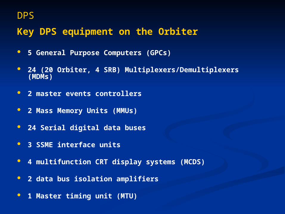
DPS
Key DPS equipment on the Orbiter
5 General Purpose Computers (GPCs)
24 (20 Orbiter, 4 SRB) Multiplexers/Demultiplexers (MDMs)
2 master events controllers
2 Mass Memory Units (MMUs)
24 Serial digital data buses
3 SSME interface units
4 multifunction CRT display systems (MCDS)
2 data bus isolation amplifiers
1 Master timing unit (MTU)
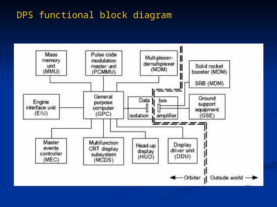
DPS functional block diagram

General Purpose Computers (GPCs)
DPS - General Purpose Computers
IBM was awarded the development contract for the STS data processing and integration and for the KSC launch processing system, and for the JSC mission control center data processing
IBM was chosen for its integrated software capability for data management on the STS Vehicle processing Prelaunch and launch Orbital flight Landing
Software modifications and changes required for each mission were simplified by developing the digital data systems through the same primary contractor
DPS - General Purpose Computers
Off-the-shelf components were emphasized for reliability and rapid integration into the STS
An existing model of IBM's AP-101 32-bit computer was adopted
GPC processor was a modified IBM System/4 Pi Initially used as central processor in earlier B-52
digital systems and later in the B-1 bomber
Included an assembly language-based software called High-order Assembly Language/Shuttle (HAL/S)
DPS - General Purpose Computers
GPC is divided into two major components
Central Processor Unit (CPU) CPU provides control logic and computational capabilities
Input/Output Processor (IOP) IOP provides control and interface links between the CPU
and the hardware that interfaces with the GPCs
Both the CPU and the IOP contain software and memory for data storage

GPC Schematic
DPS - General Purpose Computers
Basic functions
CPU Instruction execution Data storage Data manipulation
Input/Output Processor Formats and transmits commands to vehicle systems Receives and validates data from the vehicle systems Maintains interface status with the associated CPU and with
the other GPCs Interfaces the DPS 24 data buses with its 24 processors
DPS - General Purpose Computers
Weight 30.8 kg (68 lb)
Power consumption ~ 560 W
Power source Any Main Bus
Any Essential Bus
Software Four GPCs contain PASS software (GPC 1-4)
Output polling used to determine if any of the GPCs or their computations are in error
GPC #5 runs BFS software Does not participate in the polling/voting process Used for backup control of the vehicle if the PASS
software fails or malfunctions
DPS - General Purpose Computers
External mass memory is employed to overcome the inherently small main memory available to the CPU and IOP
128 k of main memory severely restricts the vehicle operations Requires a segmented approach to the GPC's control of the
mission operations
Mission sequences are loaded into the GPC's main memory from the redundant mass memory storage units
This technique allows the entire mission execution but only in sequential bundles

DPS - General Purpose Computers
GPC main memory
Originally a ferrite core construction like Apollo guidance computers Small, individual wire-wound
iron ring for each bit
Total of 128 k capacity (half) words was later increased to 256 K by bit manipulation
Original limitation was due to the memory's large mass, high power requirement, and GPC heat load
DPS - General Purpose Computers
Timer/oscillator
GPC's timer/oscillator is used to generate signal timing for pacing the data processing cycles
Also used to determine absolute time reference
Two time references are maintained for the GPC's operations. GMT - Greenwich Mean Time MET - Mission Elapsed Time A watchdog timer is also used in the GPCs to
check on the timing register for the BFS software operations

DPS - GPC
GPC panel switchesCrew operation of the GPCs is controlled with panel switches on the GPC panel
POWER (ON/OFF)
OUTPUT (BACKUP / NORMAL / TERMINATE)
INITIAL PROGRAM LOAD
MODE (RUN / STBY / HALT)

Mass Memory Units
DPS – Mass Memory Units
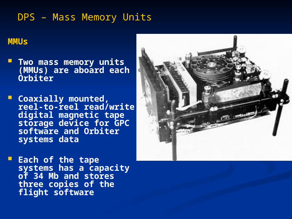
MMUs
Two mass memory units (MMUs) are aboard each Orbiter
Coaxially mounted, reel-to-reel read/write digital magnetic tape storage device for GPC software and Orbiter systems data
Each of the tape systems has a capacity of 34 Mb and stores three copies of the flight software
DPS – Mass Memory Units
The principal function of the MMU is to store the basic flight software
Secondary function is to store background formats and code for certain CRT displays and the checkpoints that are written periodically to save selected data in case the systems management GPC fails
Each mass memory data bus is connected to all five computers But each MMU is connected to only one mass memory
data bus
All MMU operations are on an on-demand basis only

Data Bus Network

DPS – Data Bus Network
Data flow in the Orbiter’s DPS systems is supported 24 data buses categorized in 7 groups
1. Flight-critical (FC) data buses (8)
2. Payload data buses (2)
3. Launch data buses (2)
4. Mass memory data buses (2)
5. Display/keyboard data buses (4)
6. Instrumentation/Pulse Code Modulation Master Unit (PCMMU) data buses (5)
7. Intercomputer communication data buses (5)
DPS – Data Bus Network
1. Flight-critical (FC) data buses (8)
FC buses tie the GPCs to: Flight-critical multiplexer/demultiplexers (MDMs) Display driver units Heads-up displays Engine interface units Master events controllers
Eight flight critical data buses combined into groups of two (FC strings) for redundancy
Each of the four FC strings can be commanded by a different GPC Group 1 FC1, FC2, FC3, FC4 Group 2 FC5, FC6, FC7, FC8

DPS – Data Bus Network
2. Payload data buses (2)
These buses tie the GPCs to the payload MDMs and the payload data interleaver (PDI)
In some configurations these are mission-dependent flex MDMs or sequence control assemblies
Two buses interface 5 GPCs and 2 payload MDMs

DPS – Data Bus Network
3. Launch data buses (2)
These buses tie the GPCs to ground support equipment, launch forward MDMs, launch aft MDMs, launch mid MDMs, SRB MDMs, and the manipulator controller interface unit (MCIU) used by the remote manipulator system
Two launch data buses are used to interconnect the following: 5 GPCs Ground support equipment Launch processing system 3 Launch MDMs 2 (left & right) SRB MDMs
DPS – Data Bus Network
4. Mass memory data buses (2)
The mass memory data buses are used for GPC - Mass Memory Unit transactions
Both mass memory data buses are interconnected with each GPC

DPS – Data Bus Network
5. Display/keyboard data buses (4)
Used for GPC/display electronics data transactions
Each of the four display electronics units are interconnected to each of the GPCs through the Display/keyboard data buses
DPS – Data Bus Network
6. Instrumentation/Pulse Code Modulation Master Unit (PCMMU) data buses (5)
Each of the GPCs is interconnected to two of the I/PCMMUs
DPS – Data Bus Network
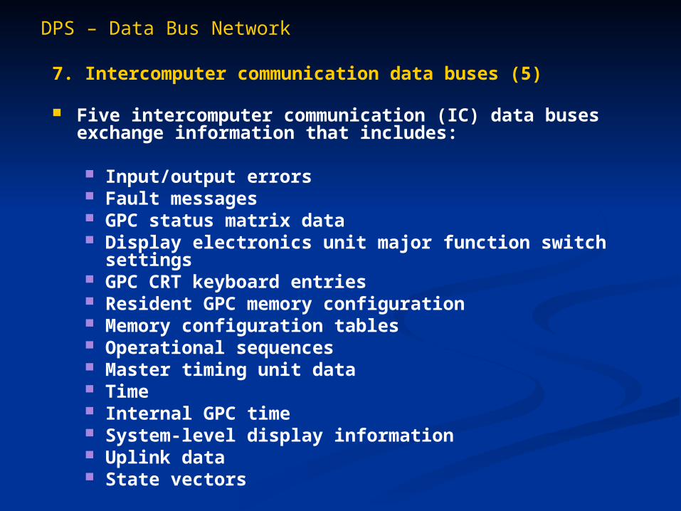
7. Intercomputer communication data buses (5)
Five intercomputer communication (IC) data buses exchange information that includes:
Input/output errors Fault messages GPC status matrix data Display electronics unit major function switch settings GPC CRT keyboard entries Resident GPC memory configuration Memory configuration tables Operational sequences Master timing unit data Time Internal GPC time System-level display information Uplink data State vectors
DPS – Data Bus Network
With the exception of the Instrumentation/PCMMU, each data bus is connected to each GPC, but only one GPC transmits over a bus at any one time
Multiplexers/Demultiplexers (MDMs)
DPS – MDMs
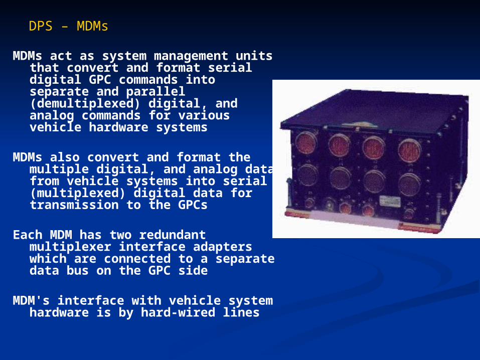
MDMs act as system management units that convert and format serial digital GPC commands into separate and parallel (demultiplexed) digital, and analog commands for various vehicle hardware systems
MDMs also convert and format the multiple digital, and analog data from vehicle systems into serial (multiplexed) digital data for transmission to the GPCs
Each MDM has two redundant multiplexer interface adapters which are connected to a separate data bus on the GPC side
MDM's interface with vehicle system hardware is by hard-wired lines

DPS – MDMs
Each Orbiter carries 23 multiplexers/demultiplexers onboard
Sixteen MDMs are an integral part of the DPS, connected directly to the GPCs and named according to their location in the vehicle and hardware interface
Remaining seven MDMs are part of the vehicle instrumentation system
Send vehicle instrumentation data to the pulse code modulation master unit
DPS – MDMs
The data processing system MDMs consist of: Flight-critical forward MDMs 1 through 4 Flight-critical aft MDMs 1 through 4 Payload MDMs 1 and 2 SRB launch left MDMs 1 and 2 SRB launch right MDMs 1 and 2 GSE/LPS launch forward 1 and launch aft 1

Software

DPS – Software
Data Processing System software is divided into two functional groups
1. System software
2. Applications software
Both are further subdivided into operations functions
Primary Orbiter flight software Called the Primary Avionics Software System (PASS) software Used to control the vehicle, vehicle systems, and
communications during its mission
Second flight software program runs on a separate GPC as a backup for critical operations Called the Backup Flight System (BFS)
DPS – Software
System software consists of three program sets
1. Flight Computer Operating System (FCOS) This is the executive software that controls the
processors, monitors key system parameters, allocates computer resources, manages program interrupts, and updates computer memory
2. User interface programs These provide instructions for processing flight crew
commands or requests
3. System control program These initialize each GPC and arrange for multi-GPC
operation during flight-critical phases

DPS – Software
Applications software performs the functions required to operate the vehicle and its systems
To conserve main memory, the applications soft-ware is divided into three major functions
1. Guidance, navigation, and control (GNC)
2. Systems management (SM)
3. Payload (PL)

DPS – Software
Applications software
1. Guidance, navigation, and control (GNC)
Specific software required for launch, ascent to orbit, maneuvering in orbit, entry, and landing
Only major function where redundant set synchronization occurs
Polling circuitry used to evaluate GPC output/calculations in synchronization
DPS – Software
Applications software
2. Systems management (SM)
This software executes tasks that monitor various orbiter systems, such as life support, thermal control, communications, and payload operations
SM is a simplex function The DPS simplex operations use a watchdog
timer to evaluate self-consistent results
DPS – Software
Applications software
3. Payload (PL)
The payload major function runs mass memory utility software
Because the PL major function is usually unsupported in flight, none of the GPCs are loaded with PL software
Only used in vehicle preprocessing at KSC, and is a simplex major function
DPS – Software
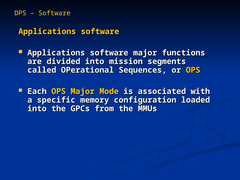
Applications softwareApplications software
Applications software major functions are Applications software major functions are divided into mission segments called divided into mission segments called OPerational Sequences, or OPerational Sequences, or OPSOPS
Each Each OPS Major ModeOPS Major Mode is associated with a is associated with a specific memory configuration loaded into the specific memory configuration loaded into the GPCs from the MMUs GPCs from the MMUs
DPS – Software
Applications software
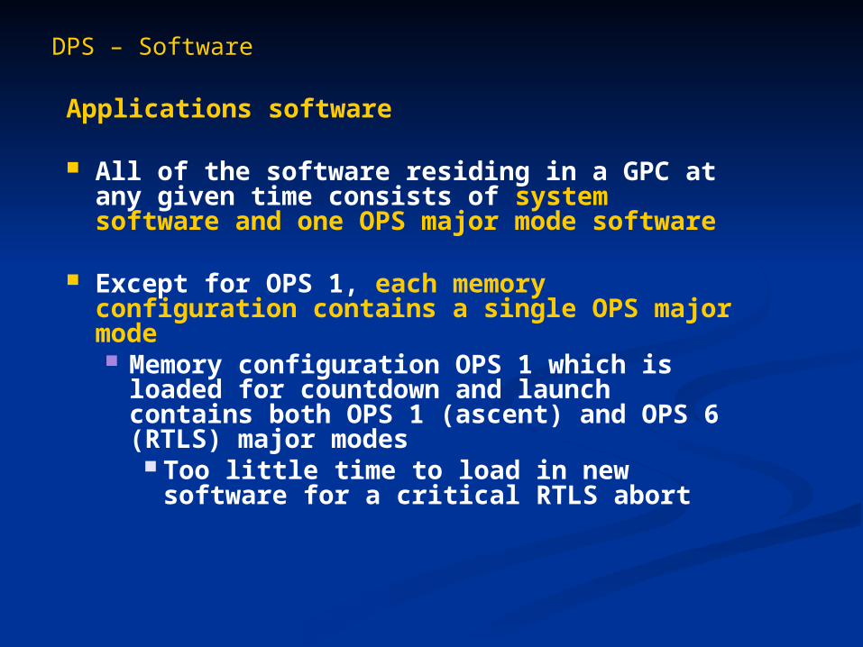
All of the software residing in a GPC at any given time consists of system software and one OPS major mode software
Except for OPS 1, each memory configuration contains a single OPS major mode Memory configuration OPS 1 which is
loaded for countdown and launch contains both OPS 1 (ascent) and OPS 6 (RTLS) major modes
Too little time to load in new software for a critical RTLS abort

DPS – Software
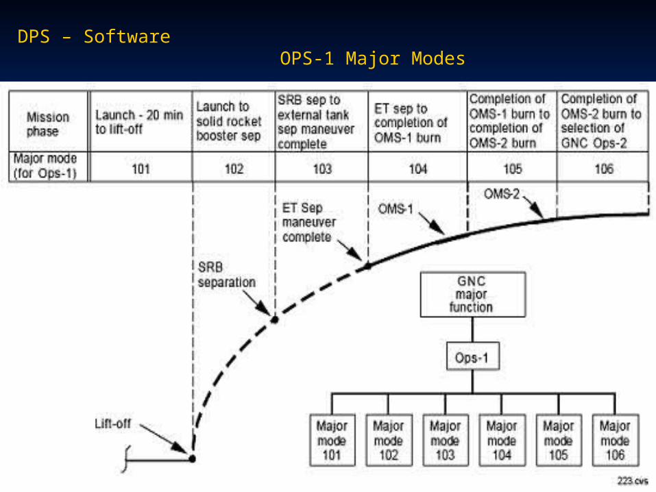
DPS – Software OPS-1 Major Modes
DPS – Software
Backup Flight System (BFS)Backup Flight System (BFS)
Backup Flight System software is an entirely Backup Flight System software is an entirely separate DPS software package maintained on separate DPS software package maintained on the Orbiter's fifth GPCthe Orbiter's fifth GPC GPC selection for BFS operation can be GPC selection for BFS operation can be
changed manually with panel switcheschanged manually with panel switches
BFS flight software mimics the PASS software BFS flight software mimics the PASS software for the mission-critical operations (OPS 1, OPS for the mission-critical operations (OPS 1, OPS 3 and OPS 6)3 and OPS 6) Contains notable differencesContains notable differences
DPS – Software
Backup Flight System (BFS)
BFS software is written by a different vendor Also in the HAL/S language
BFS software is simpler than the PASS software since it is used for contingencies in the mission; the critical phases of flight Smaller size of the BFS software allows it to be
loaded completely into one GPC for the entire mission and does not require sequential loading
Copies of the BFS are contained on both of the MMUs
DPS – Software
Backup Flight System (BFS)
BFS software is programmed to monitor the state of the GPC and PASS operations so that it would be possible to take control of the vehicle if the PASS software to malfunction
Like PASS, the BFS includes both applications software and system software
Unlike PASS software, BFS is small enough to run both applications and systems application simultaneously
DPS – Software
Backup Flight System (BFS)
System functions on the BFS include Time-keeping PASS/BFS interface Multifunction CRT display system operations GPC I/O Communications uplink and downlink

DPS – Software
Backup Flight System (BFS)
BFS software can be selected with the engage and disengage control switch on the hand conroller BFS can take over control of the vehicle by
pressing the engage button on the top of the flight crew's rotational hand controllers
BFS also executes system management software (SM) in simplex during ascent and entry since the other four GPCs running PASS software are operating in GNC in redundant set synchronization
BFS provides only limited support for on-orbit operations via MM 106 or MM 301

References
Shuttle Crew Operations Manual - Digital Processing System (DPS), NASA
National Space Transportation System Press Kit, NASA, 1998