Space Power Topology Selection and its System Level ...
18
J. Aerosp. Technol. Manag., São José dos Campos, v12, e2720, 2020 INTRODUCTION e power supply subsystem of a satellite (PSS) is responsible for the generation, storage, conditioning and distribution of energy to the various spacecraſt loads. Since the first satellite launched in 1957 (Sputnik), with a weight of about 83.6 kg and payload electric power of the order of 1 W (Hyder et al. 2000), it has been observed a gradual increase in the onboard electric power availability, which is accompanied by an increase of the subsystem mass. According to Patel (2004), the PSS represents about 25 to 40% of the total mass of a satellite, whose impact on launch cost cannot be leſt aside since the average cost of the launch in 2002 used to be US$ 10,000/kg for low orbit (LEO) and US$ 50,000/kg for geostationary orbit (GEO). A report published in 2018 by the Federal Aviation Administration cites, for example, that the cost for launching the Falcon 9 rocket starts from US$5,000/kg (LEO) while for the more reliable Atlas V launcher starts from US$13,000/kg in the same orbit (FAA 2018). erefore, the challenges related to choosing the most optimized topology are accompanied by more demanding requirements of mass and efficiency imposed on the system. Aimed at contributing to future developments of the Brazilian Space Program, this article wishes to answer what is the roadmap for power supply subsystems for Brazilian satellites, since the new launchers for the next generation of space missions (CBERS 5/6 and Amazônia satellites) shall be smaller and of lower cost, implying necessarily a reduction of the mass of the current systems developed at the National Institute of Space Research (INPE, Instituto Nacional de Pesquisas Espaciais). To answer this question, https://doi.org/10.5028/jatm.v12.1158 REVIEW ARTICLE 1.Instituto Nacional de Pesquisas Espaciais – Engenharia e Tecnologia Espaciais – Divisão de Eletrônica Aeroespacial – São José dos Campos/SP – Brazil *Correspondence author: [email protected] Received: Nov. 13, 2018 | Accepted: Feb. 13, 2020 Section Editor: Alison Moraes ABSTRACT: This article analyses the main candidate topologies for power supply for low earth orbit satellite applications, which are considered from the standpoint of energy continuity and power balance. The system components are dealt with as energy port elements through which energy is exchanged along the system. A comparative study and selection of the optimal topology were carried out, according to a criteria of mass/volume reduction and system efficiency improvement. The comparison was made between a three-domain controlled (fully regulated) and a two-domain controlled (also called hybrid) bus topology. After selection, a description of the design of the system control was given, considering the battery charge regulator (BCR) and battery discharge regulator (BDR) as a unified battery power conditioning equipment integrated into a single bidirectional converter. The system design was validated with a Simulink based model with the selected topology being controlled in closed loop to provide a regulated 28 V primary power bus. Finally, the article presents the current prototyping under development. KEYWORDS: Switching power supply; Energy bonds; Satellite power supply; Fully regulated topology; Bidirectional DC/DC converter. Space Power Topology Selection and its System Level Modeling and Control Renato Oliveira de Magalhães 1,* , Herbi Junior Pereira Moreira 1 Magalhães RO; Moreira HJP (2020) Space Power Topology Selection and its System Level Modeling and Control. J Aerosp Technol Manag, 12: e2720. https://doi.org/10.5028/ jatm.v12.1158 How to cite Magalhães RO https://orcid.org/0000-0003-2989-2156 Moreira HJP https://orcid.org/0000-0003-4313-2372
Transcript of Space Power Topology Selection and its System Level ...

1
J. Aerosp. Technol. Manag., São José dos Campos, v12, e2720, 2020
INTRODUCTION
The power supply subsystem of a satellite (PSS) is responsible for the generation, storage, conditioning and distribution of energy to the various spacecraft loads. Since the first satellite launched in 1957 (Sputnik), with a weight of about 83.6 kg and payload electric power of the order of 1 W (Hyder et al. 2000), it has been observed a gradual increase in the onboard electric power availability, which is accompanied by an increase of the subsystem mass. According to Patel (2004), the PSS represents about 25 to 40% of the total mass of a satellite, whose impact on launch cost cannot be left aside since the average cost of the launch in 2002 used to be US$ 10,000/kg for low orbit (LEO) and US$ 50,000/kg for geostationary orbit (GEO). A report published in 2018 by the Federal Aviation Administration cites, for example, that the cost for launching the Falcon 9 rocket starts from US$5,000/kg (LEO) while for the more reliable Atlas V launcher starts from US$13,000/kg in the same orbit (FAA 2018). Therefore, the challenges related to choosing the most optimized topology are accompanied by more demanding requirements of mass and efficiency imposed on the system.
Aimed at contributing to future developments of the Brazilian Space Program, this article wishes to answer what is the roadmap for power supply subsystems for Brazilian satellites, since the new launchers for the next generation of space missions (CBERS 5/6 and Amazônia satellites) shall be smaller and of lower cost, implying necessarily a reduction of the mass of the current systems developed at the National Institute of Space Research (INPE, Instituto Nacional de Pesquisas Espaciais). To answer this question,
https://doi.org/10.5028/jatm.v12.1158 REVIEW ARTICLE
1.Instituto Nacional de Pesquisas Espaciais – Engenharia e Tecnologia Espaciais – Divisão de Eletrônica Aeroespacial – São José dos Campos/SP – Brazil
*Correspondence author: [email protected]
Received: Nov. 13, 2018 | Accepted: Feb. 13, 2020
Section Editor: Alison Moraes
ABSTRACT: This article analyses the main candidate topologies for power supply for low earth orbit satellite applications, which are considered from the standpoint of energy continuity and power balance. The system components are dealt with as energy port elements through which energy is exchanged along the system. A comparative study and selection of the optimal topology were carried out, according to a criteria of mass/volume reduction and system efficiency improvement. The comparison was made between a three-domain controlled (fully regulated) and a two-domain controlled (also called hybrid) bus topology. After selection, a description of the design of the system control was given, considering the battery charge regulator (BCR) and battery discharge regulator (BDR) as a unified battery power conditioning equipment integrated into a single bidirectional converter. The system design was validated with a Simulink based model with the selected topology being controlled in closed loop to provide a regulated 28 V primary power bus. Finally, the article presents the current prototyping under development.
KEYWORDS: Switching power supply; Energy bonds; Satellite power supply; Fully regulated topology; Bidirectional DC/DC converter.
Space Power Topology Selection and its System Level Modeling and ControlRenato Oliveira de Magalhães1,*, Herbi Junior Pereira Moreira1
Magalhães RO; Moreira HJP (2020) Space Power Topology Selection and its System Level Modeling and Control. J Aerosp Technol Manag, 12: e2720. https://doi.org/10.5028/jatm.v12.1158
How to cite
Magalhães RO https://orcid.org/0000-0003-2989-2156
Moreira HJP https://orcid.org/0000-0003-4313-2372

J. Aerosp. Technol. Manag., São José dos Campos, v12, e2720, 2020
Magalhães RO, Moreira HJP2
this paper proposes a study of the impact of the choice of power conditioning and distribution unit (PCDU) topologies on the overall efficiency and mass of the power supply subsystem. This is an old task with first studies performed by the European Space Agency (ESA) in the 1980s (O’Sullivan 1989), where the author concludes that the optimal topology for low earth orbit is the hybrid one, being the fully regulated topology recommended for geostationary orbits.
However, with the technological advancement and the emergence of new integrated circuit controllers in the industry, with application to bidirectional converters, both control functions of charge and discharge of the battery can be condensed more easily into a single module, suggesting that the fully regulated topology might become more available for low earth orbit missions nowadays, with the advantage of being more efficient in terms of the use of the solar generator when compared to the hybrid topology.
The topology selection was analyzed by means of a general approach for the modeling of interacting energetic components, or energy ports, of the various subsystem components, known as bond graphs. After modeling, the article follows with the design of a closed loop system that regulates the voltage of a primary power bus, designed to feed the various spacecraft loads. Prototyping the system is an ongoing activity and the modules already manufactured are shown together with a description of what is still missing and will be left as future work.
SATELLITE POWER SYSTEM CONCEPTS
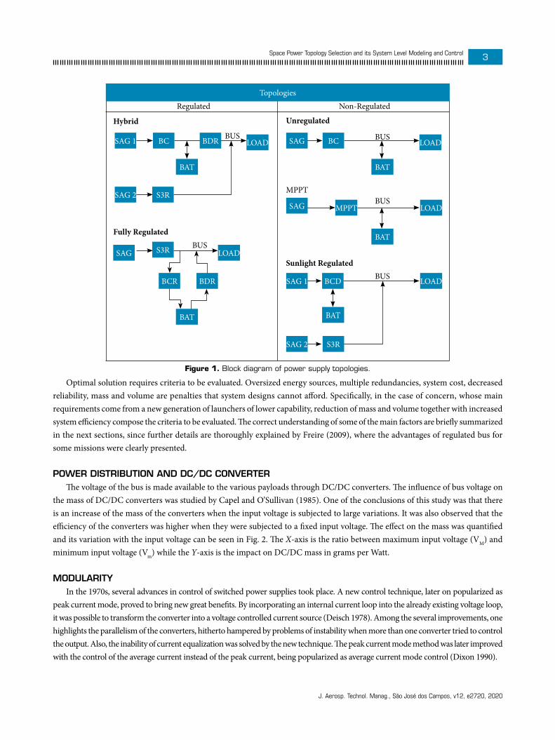
There are many topologies being used by satellite power supply systems, whose main requirements, basic rules and four general principles are established by standards, such as the European Space Agency standard for space engineering (ECSS-E-ST-20C 2008). Generally, these topologies can be classified into the main categories listed below:• Nonregulated bus
• Maximum peak power tracking (MPPT);• Unregulated power bus voltage;• Sunlight regulated power bus.
• Regulated Bus• Fully regulated power bus voltage;• Hybrid regulated power bus voltage.The block diagrams for each of these topologies can be viewed in Fig. 1.The dilemma of topology choice is always a problem whose answer is the optimal design, in terms of mass budget, electrical
performance, modularity and cost, that meet mission requirements. To give an overview of the many studies seeking an answer for such a problem, this article reviewed the main points of the subject summarized in a previous dissertation (Freire 2009). Generally, there is no unique optimal solution due to the variety of system component characteristics and mission requirements. Also, an optimal solution today might not be so in the future if technology advance plays a significant role in system upgrade.
So, how one can answer this problem? By reviewing the literature, the conclusion was that software tools have been the way to attack the problem. Nevertheless, they are not always looking for an optimal topology. In many cases, in the reviewed literature, software tools have been developed specifically for the design verification of some mission or topology. An article from Capel et al. (1982) describes an approach for the modeling of system components such as solar arrays, batteries and power conditioning units applied to the ERS-1 mission whose topology belongs to the unregulated bus category. In the same direction, Lee et al. (1988) described another system component approach for simulation and design verification for a specific mission by means of a software named EASY5.
Selection of optimal topology can be found in the use of the software POWERCAP, through which a trade-off study of three topologies (regulated, unregulated and hybrid bus) was developed for the Skybridge constellation’s power system (Capel and Defoug 1999). Also, with the same POWERCAP software, Zimmermann et al. (2008) analyzed nonregulated and regulated topologies for a synthetic aperture radar (SAR) mission.
J. Aerosp. Technol. Manag., São José dos Campos, v12, e2720, 2020
Space Power Topology Selection and its System Level Modeling and Control 3
Topologies
SAG 1
SAG 1
SAG 2
SAG 2
S3R
S3R
S3R
SAG
SAG
SAG
BAT
BAT
BATBAT
BAT
BUS
BUS
BUS
BUS
BUS
Regulated Non-Regulated
Hybrid
Fully Regulated
Unregulated
MPPT
Sunlight Regulated
LOAD
LOAD
LOAD
LOADMPPT
LOAD
BDRBC
BCR BDR BCD
BC
Figure 1. Block diagram of power supply topologies.
Optimal solution requires criteria to be evaluated. Oversized energy sources, multiple redundancies, system cost, decreased reliability, mass and volume are penalties that system designs cannot afford. Specifically, in the case of concern, whose main requirements come from a new generation of launchers of lower capability, reduction of mass and volume together with increased system efficiency compose the criteria to be evaluated. The correct understanding of some of the main factors are briefly summarized in the next sections, since further details are thoroughly explained by Freire (2009), where the advantages of regulated bus for some missions were clearly presented.
POWER DISTRIBUTION AND DC/DC CONVERTERThe voltage of the bus is made available to the various payloads through DC/DC converters. The influence of bus voltage on
the mass of DC/DC converters was studied by Capel and O’Sullivan (1985). One of the conclusions of this study was that there is an increase of the mass of the converters when the input voltage is subjected to large variations. It was also observed that the efficiency of the converters was higher when they were subjected to a fixed input voltage. The effect on the mass was quantified and its variation with the input voltage can be seen in Fig. 2. The X-axis is the ratio between maximum input voltage (VM) and minimum input voltage (Vm) while the Y-axis is the impact on DC/DC mass in grams per Watt.
MODULARITYIn the 1970s, several advances in control of switched power supplies took place. A new control technique, later on popularized as
peak current mode, proved to bring new great benefits. By incorporating an internal current loop into the already existing voltage loop, it was possible to transform the converter into a voltage controlled current source (Deisch 1978). Among the several improvements, one highlights the parallelism of the converters, hitherto hampered by problems of instability when more than one converter tried to control the output. Also, the inability of current equalization was solved by the new technique. The peak current mode method was later improved with the control of the average current instead of the peak current, being popularized as average current mode control (Dixon 1990).

J. Aerosp. Technol. Manag., São José dos Campos, v12, e2720, 2020
Magalhães RO, Moreira HJP4
@Fsw = 100kHz
B = VM/Vm
1 1.1 1.6 2.0
21.2
17
10.2
10
g/W
Figure 2. DC/DC mass impact due to input voltage variation. Adapted from Capel and O’Sullivan (1985).
Another very much popularized method of parallelism is the use of S3R design, which stands for sequential shunt switching regulators (O’Sullivan and Weinberg 1977). This modular approach has been adopted to divide the total solar array current into as many channels as needed by the design. These modularizing techniques are the central core for the system proposed in this article (Fig. 3).
Modularity is also a key point in the reuse of module designs, improving dramatically cost and manufacturing schedules.
II
+-
Ref
1
2SA1
SA2
SAn
Solar Srray Channels
iS3R
n
υOUT
Current SourceConverter
Current SourceConverter
Current SourceConverter
(a) (b)
Figure 3. S3R (a) and average current mode (b) modularizing techniques.
EFFICIENT USE OF SOLAR PANELSWhenever a solar array is directly connected to a voltage source, its operating point is defined by the voltage of this source.
This direct connection, shown in Fig. 4, is the type of connection of the blocks BC and S3R in Fig. 1.In the fully regulated topology, the solar array generator (SAG) is designed to have its maximum power point close to the regulated
bus voltage. Therefore, the SAG is optimized as a power source. This is not the case in the hybrid topology. While SAG2 works close to its maximum power point, the same does not happen to SAG1, since every time the satellite comes out from eclipse to sunlight, the discharged battery will impose a voltage lower than the voltage corresponding to the maximum operating point. This fact tends to be quite relevant since battery lifetime will decrease the end of discharge voltage, going further away from the maximum power point (Fig. 5).

J. Aerosp. Technol. Manag., São José dos Campos, v12, e2720, 2020
Space Power Topology Selection and its System Level Modeling and Control 5
+
-Voltage Source
SAG
Figure 4. Connection SAG/voltage source.
PPmax
Pavg
Pmin
EoD EoC Vbat
V
t
(a)
(b)
Figure 5. SAG power (a) vs battery (BAT) voltage (b). Pmax = maximum SAG power; Pavg = average between Pmax and Pmin; EoD = battery end of discharging voltage; EoC = end of charging voltage. Pmin = minimum SAG power
Adding all of this together, one of the main studies in the area (O’Sullivan 1989) reached the conclusion already stated where it claims that hybrid topology is best suited for LEO orbit whereas fully regulated being indicated for GEO orbits. This article proposes for the Brazilian missions developed at INPE the use of the fully regulated topology, with BCR and BDR amalgamated into an equipment (bidirectional DC/DC converter), for LEO orbit as an optimum topology.
BRIEF REVIEW OF BRAZILIAN SPACE PROGRAM POWER SYSTEMS
In the late 1970s, the first Brazilian space mission (MECB) was approved with the intention of developing four satellites. The MECB program represented a great challenge for the Brazilian Space Program, considering its complexity and, most of all, the premature technological domain for the development of the various subsystems that make up a satellite at the time.
The energy power system (EPS) used in these satellites was developed between 1985 and 1991 by the INPE and flew in data collection satellites (SCD-1, SCD-2A and SCD-2). The result was a power conditioning unit (PCU) made up of battery charge regulator (BCR), battery discharge regulator (BDR) and SHUNT. Also, during this period, between 1988 and 1992, the PCU of the first satellite of remote sensing (SSR-1) was developed. Table 1 shows some information related to the mentioned EPS.
Table 1. Main EPS information of first Brazilian missions.
Requirement SCD SSR
POWER 110 W 250 W
BUS TYPE Regulated Regulated

J. Aerosp. Technol. Manag., São José dos Campos, v12, e2720, 2020
Magalhães RO, Moreira HJP6
With a bilateral cooperation agreement signed between Brazil and China for the development of a remote sensing satellite: China–Brazil Earth Resource Satellite (CBERS), there was a major leap in the development of the energy subsystem, with a greater demand of power and much more complexity than the previous satellites. Several national industrial partners have established cooperation with INPE for the subsystem development.
In 2005, the project reached its second generation of CBERS satellites, culminating in the production of CBERS 3&4 (INPE 2017). The new power conditioning subsystem has doubled its power demand and new processes have been introduced, such as the use of surface-mount technology (SMT), allowing not only a significant gain in power density (mass and volume per Watt) compared to previous generation, but also a considerable reduction in size of equipment.
Table 2 compares the amount of power demand and mass of the S3R equipment and highlights the significant improvement in power compaction between the two CBERS generations.
Table 2. CBERS generations comparison for the SHUNT equipment.
Requirement CBERS 1&2 CBERS 3&4
POWER 722.4 W 1344 W
MASS 13.6 kg 6.81 kg
SPECIFIC POWER 53.1 W/kg 197.4 W/kg
Requirements to decrease mass and volume and a more efficient system is still in progress for the next generation of CBERS mission as well as for the Amazônia satellite. Therefore, it becomes crucial to review the current technical solution. Improvements aim at lighter, more compact and reliable equipment that substitute the old ones, as a result of redesign and rearrangement of configuration that utilizes previous similar modules but yields a more perfect integrated hole.
SYSTEM MODELING AND ANALYSIS
REVIEW OF LITERATUREPower supply system selection, optimized for mass and volume, was initially studied by O’Sullivan (1989) with the conclusion
already stated: Hybrid topology is optimal for LEO orbit and fully regulated is optimal for GEO. Sullivan pointed out that future technology could merge BCR and BDR functions, thus optimizing fully regulated topology, even for LEO orbit, but he didn’t go further on this.
It was only in the 1990s that this subject was brought back to European Space Power Conferences (Weinberg and Lopez 1998), with the analyses showing that for LEO orbit fully regulated topology, with bidirectional DC/DC converter for battery charging and discharging, is optimal in terms of mass and volume. The above cited authors implemented a software-based system analysis, computing the total mass necessary for each topology. Weinberg and Lopez (1998) claim that Mata and Rueda (1993) were the first to present the possibility of merging BCR and BDR in the same bidirectional converter. Weinberg and Lopez (1998) extended this previous study from a system point of view and concluded that fully regulated topology with BCDR was an optimal solution, in terms of mass and volume, especially for LEO orbit, where the lower sunlight time to recharge the battery demands higher power for the converter. This solution was again discussed by Pedersen et al. (2008), but the author focused only on the solution aspect of the bidirectional DC/DC converters without a system analysis.
Topology with bidirectional DC/DC converters appears again in Schirone and Macellari (2014) as a solution for a lunar rover with a topology that makes use of four switches. A fully regulated solution with a block diagram showing a BCDR equipment was presented by Bonnet et al. (2017). Nevertheless, the BCR and BDR functions are separated and not performed by bidirectional DC/DC converter,

J. Aerosp. Technol. Manag., São José dos Campos, v12, e2720, 2020
Space Power Topology Selection and its System Level Modeling and Control 7
with discussions focused on modular and decentralized architectures of the PCU. Reference to bidirectional DC/DC converter is shown in Ramachandran and Nymand (2017), where the authors claim that such converters display higher efficiency, but in a full bridge topology implemented with a high number of switches and out of the context of PCU.
The technology related to bidirectional DC/DC converters has gained considerable attention and improvements in automobile industry and in the context of renewable energy systems, with integrated circuits being manufactured for specific applications (Weinberg and Lopez 1998).
This section shows that a different approach leads to the same conclusion, but with the system analysis carried out through an energy approach, known as bondgraphs. The topology S4R discussed by Capel and Perol (2002) was not considered in this research. Although promising, it imposes battery voltages bellow bus voltages and the series regulator inserted in the control scheme represents an additional equipment when compared to the optimal solution derived in the following sections.
TOPOLOGY MODELING WITH ENERGY BONDSRegulated bus power conditioning can be implemented by three topologies: Hybrid and Fully Regulated already presented in
block diagram form in previous sections, where Fully Regulated will now be divided into two subcategories, that is, unidirectional and bidirectional, the difference between them being the existence of a bidirectional DC/DC converter for battery power processing. Power flow in this type of system can be easily visualized by the bond graph method (Takahashi et al. 1972; Paynter 1960). The corresponding energy bond diagrams for each topology are given in Fig. 6.
The first main conclusion that has been reached concerns the power processing capability for each topology, and can be summarized as: for each kW demanded by the load,• The hybrid topology has 3 kW of processing power equipment;• The fully regulated unidirectional has 4 kW of processing power equipment;• The fully regulated bidirectional has 3 kW of processing power equipment.
For the sake of simplicity, it is assumed there is no power dissipation in the flux between elements. For hybrid topology, during sunlight, there is 1 kW flowing through S3R to provide power to the load and 1 kW flowing through BCR to recharge the batteries, which were discharged by BDR that processed 1 kW to provide power to the load during eclipse. For fully regulated unidirectional topology, S3R must process 2 kW of power, with 1 kW delivered to the load and the other 1 kW delivered to BCR to recharge the batteries that were discharged by BDR, which processed 1 kW to provide power to the load during eclipse. When the BDR and BCR functions merge into a single piece of equipment, the power that was split between the two is now located into a single module, thus totalizing 3 kW of processing power for 1 kW demanded by load. The result is summarized in Table 3.
For the case of LEO orbit, where the short sunlight time implies a fast recharge of the battery, high battery-charging current is necessary and, thus, high-power equipment is demanded for this function. So, at this point one can say that the hybrid topology needs 1 kW DC/DC converter to charge the battery (BCR), 1 kW DC/DC converter to discharge the battery (BDR) and 1 kW S3R module to power the bus. The fully unidirectional topology also needs two separate DC/DC converters for battery charging and discharging and a 2kW S3R.
It is important to remember that designing separate DC/DC converters demands two different mechanical frames for component mounting and power dissipation. Therefore, what Table 3 shows is that the fully bidirectional topology would need two aluminum mechanical frames to perform PCU function, while the two others would need three different aluminum mechanical frames. The greater the number of aluminum frames, the greater the volume and mass of the PCDU.
By considering the power flow through the system, taking into account the equipment’s efficiency, the total efficiency of the system as a whole can be estimated. System efficiency here shall be understood as the ratio between the power bus demand and the total installed SAG power. It is important to emphasize that the system is supposed to operate in stationary regime, with no transient taking place.

J. Aerosp. Technol. Manag., São José dos Campos, v12, e2720, 2020
Magalhães RO, Moreira HJP8
Hybrid
Fully Regulated Unidirectional
Fully Regulated Bidirectional
SAG1
SAG1
SAG1
SAG2
S3R
S3R
S3R
CAP
CAP
CAP
e1
e1
e1
f1
f1
f1
e2
e2
e2
f2
f2
f2
e3
e3
e3
f3
f3
f3
0 0
0
0
e5
e5
e4
e4
e4
e7
e7
e8
e5
e6
e8
e9
f4
f4
f4
f7
f7
f8
f5
f6
f8
f9
f5
f5
e6
e6
f6
f6
BAT
BAT
BAT
BCDR
BCR BDR
BDRBDR
LOAD
LOAD
LOAD
Figure 6. Topologies energy bond diagrams.
Now, for the reason already explained above, every time there is a portion of the SAG connected to a battery, there is a penalty of oversizing the solar array due to the low-battery voltage at the end of eclipse and beginning of sunlight. The power P1 needed at bond junction SAG1-BCR in the hybrid topology is the average power (Pavg) shown in Fig. 5. Therefore the maximum installed power of SAG is the average power divided by a factor ξ, which will be named as SAG hybrid factor, equal to the ratio Pavg/Pmax. The system efficiency will be computed from SAG power needed to be installed for each kilowatt of payload.

J. Aerosp. Technol. Manag., São José dos Campos, v12, e2720, 2020
Space Power Topology Selection and its System Level Modeling and Control 9
Table 3. Topologies power processing comparison.
EquipamentHybrid Fully Unidirectional Fully Bidirectional
Sunlight Eclipse Sunlight Eclipse Sunlight Eclipse
S3R 1 kW - 2 kW - 2 kW -
BCR 1 kW - 1 kW - - -
BDR - 1 kW - 1 kW - -
BCDR - - - - 1 kW
Total Equipment Processing
Power
3 kW 4 kW 3 kW
Table 4 shows the result of the analysis. In order to be able to determine the size of the solar panel correctly, the efficiency of each equipment was taken into account as indicated in Fig. 7. It can be seen that there is a power flow between P6 up to P1 and P9 for the hybrid topology, defined as follows: P6 (which corresponds to each kilowatt of load) is equal to P8 minus P7 (junction type 0) during sunlight, supposing S3R has enough power to source the load, thus P5 equals to zero; P8 is reflected into P9 through the efficiency of S3R. Meanwhile, SAG1 is recharging the battery. Therefore, P4 is equal to P2 (junction type 0) which, in turn, is reflected into P1 by the BCR efficiency. During eclipse, there is a power flow from battery to bus via BDR. P5 is reflected into P3 by means of the BDR efficiency. In the fully bidirectional topology, during sunlight, there is the current supply through the S3R for the load and recharging of the battery, therefore P3 is equal to P2 minus (P4 + P5), considering that the power through S3R is sufficient to sustain both demands simultaneously. P2 is reflected into P1, considering the efficiency of S3R. During eclipse, the battery maintains P3 via BCDR. P5 is reflected into P6 by the efficiency of the BCDR. In summary, the total installed power of the SAG for the hybrid topology is the sum of the powers P9 plus P1/ξ, whereas it is P1 for fully bidirectional. Table 4 shows the result of fully bidirectional having efficiency higher than hybrid (η=0.61 compared to η=0.57). The greater the solar panel, the greater is the system mass and its cost. Therefore, one objective has been reached, demonstrating that fully regulated bidirectional topology is optimal for LEO orbit.
Table 4. System efficiency comparison between hybrid and fully regulated bidirectional.
Input dataCalculated Data
Hybrid Fully bidirectional
Pload 1000 W Sunlight Eclipse Sunlight Eclipse
ηBCRhib 0.98 P1 590.8 W 1642.3 W
ηBDR 0.95 P2 578.9 W 1609.4 W
ηS3R 0.98 P3 1052.6 W 1000.0 W 1000.0 W
ηBCDR 0.95 P4 578.9 W 1052.6 W
ɛ 0.81 P5 1000.0 W 609.4 W 1000.0 W
Recharge factor 1.1 P6 1000.0 W 578.9 W 1052.6 W
tECLIPSE 30 min P8 1000.0 W
tSUNLIGHT 60 min P9 1020.4 W
P_SAG_TOTAL 1749.7 W 1642.3 W
η 0.57 0.61
BAT_Drained Energy During Eclipse 526.3 Wh 526.3 Wh

J. Aerosp. Technol. Manag., São José dos Campos, v12, e2720, 2020
Magalhães RO, Moreira HJP10
Hybrid
Fully Regulated Unidirectional
Fully Regulated Bidirectional
SAG1
SAG1
SAG1
SAG2
S3R
S3R
S3R
CAP
CAP
CAP
P1
P1
P1
P2
P2
P2
P3
P3
P3
0 0
0
0
P5
P5
P4
P4
P4
P7
P7
P8
P5
P6
P9
P8
P6
P6
BAT
BAT
BAT
BCDR
BCRηBCR_hib ηBCR
ηBCR ηBDR
ηBCDR
ηS3R
ηS3R
ηS3R
BDR
BDRBDR
LOAD
LOAD
LOAD
Figure 7. System efficiency in bond diagram.
CLOSED LOOP SYSTEM MODELING AND SIMULATION
This section presents a Simulink based model to simulate the subsystem control problem. The main requirement is the regulation of the main bus voltage, which is accomplished by the main error amplifier (MEA) controller, the heart of the system. The control principles are based on the conductance control and three-domain control (O’Sullivan 1989). A schematic can be viewed in Fig. 8 and Fig. 9. The MEA senses the voltage of the bus in the capacitor bank, compares it to a reference voltage and controls the currents at capacitor bank node, equalizing current sources and sinks to keep the bus voltage stabilized. During sunlight, when the SAG has enough power to provide the bus demand and recharge the battery, the first control mode is to adjust the S3R current

J. Aerosp. Technol. Manag., São José dos Campos, v12, e2720, 2020
Space Power Topology Selection and its System Level Modeling and Control 11
(iS = iSAG - iS3R = iC + iLOAD). If SAG current (iSAG) falls or there is a peak power demand above S3R capability, it starts to control battery charging current iC, by decreasing it to equalize bus node current (BCR mode with iS = iC + iLOAD). If there is no SAG, it goes to the third mode (BDR mode) where energy is taken from battery to provide necessary current to the bus (iD = ILOAD).
BCDR
S3R
iS3R
iC iD
iS
iBCDR
iLOAD
MEA
LOA
DSAG
BAT
REF
BUS
Capacitor Bank
H
Figure 8. Fully regulated closed loop block diagram. Adapted from O’Sullivan (1989).
υBDR υBCR υMEAυS3Rmin
IBDRmáx
IS3Rmáx
ICHARGE
υS3Rmáx
BDRmode
BCRmode
S3R mode
iDiCiS
iD, iC, iS
Figure 9. Three-domain control.
The BCDR block during eclipse, discharges the battery operating as a Buck regulator since in the configuration used, it’s supposed vbat > vbus. During sunlight, the BCDR works as a boost, taking power from the bus to recharge the battery. The typical charging method for a lithium-ion battery to be used in this system includes a constant current (CC) charge to a voltage of 3.9 to 4.2 V and keep at constant voltage (CV), while the current falls down (McKissock et al. 2009). The averaged model of the BCDR, connecting battery and bus is shown in Fig. 10.

J. Aerosp. Technol. Manag., São José dos Campos, v12, e2720, 2020
Magalhães RO, Moreira HJP12
+
-
+
υbat
-
+
υbus
-
iL
dvbatdiL
Figure 10. Half-bridge average model.
Although three-domain control of such system were presented by Weinberg and Lopez (1998) and Mata and Rueda (1993), the authors did not give details of the control modelling. In this article, the three-domain control by means of conductance control is given in detail, as shown in the block diagram in Fig. 11.
+
+
+
-
-
-
MEA
BAT diL
iL
iL
d
dυBAT
Plant
SAG
LOAD
MOD
H3
H2
H1
MEACOND
1
MEACOND
2
MajorityVoter
C2(s)
C1(s)
υMEA
υbus
VEoC
Figure 11. Conductance control.
The modelling approach considered here shows that the plant or process to be controlled is a one-input/one-output system. The inner feedback current loop inside BCDR was considered as an intrinsic part of the plant, because in the end, it transforms the DC/DC converter in a voltage-controlled current source, the same occurring for S3R. This is an immense simplification as the whole plant is transformed into a first order system with only one integrator: the capacitor bank, with currents being sourced and sank from it. Nevertheless, it is important to emphasize that the objective of this simulation is to demonstrate the feasibility of the fully regulated control scheme with bidirectional DC/DC converter, showing the feasibility to insert it into the three-domain and conductance control technique. It is not the intention of this article to delve into the control performance of the bidirectional DC/DC converter, such as transients of the BCDR module, a task which is left as future work where a fine tuning for recovery time, overshoot and stability will be explored.
For the time being, it has proved sufficient to consider the MEA controller as a simple PI controller. As said, the BCDR is based on the average current mode control method, allowing paralleling DC/DC converters with equal shared currents. In this control scheme, MEA is the outer voltage loop generating the current reference for the inner current loop.
The simulation was based on a standby bus power consumption followed by a payload peak power demand during sunlight, a typical nominal operating mode of a remote sensing satellite equipped with optical cameras. The parameters of the simulations are shown in Table 5. The simulation results are presented in Fig. 12 and Fig. 13.

J. Aerosp. Technol. Manag., São José dos Campos, v12, e2720, 2020
Space Power Topology Selection and its System Level Modeling and Control 13
Table 5. Three-domain control parameters.
THREE-DOMAIN CONTROL PARAMETERS VALUE
S3R
VS3Rmax 20 V
VS3Rmin 12 V
IS3Rmax 48 A
BCDR
ChargeVBCR 10 V
ICHARGE 12 A
DischargeVBDR 28 V
IBDRmax 65 A
30
20
10
0
20
10
0
-10
525048464442
0 500 1000 1500 2000 2500 3000 3500 4000 4500 5000
0 500 1000 1500 2000 2500 3000 3500 4000 4500 5000
0 500 1000 1500 2000 2500 3000 3500 4000 4500 5000
Battery Current (A)
MEA Voltage (V)
Battery Voltage (V)
Time (s)
Figure 12. Simulation waveforms. Battery charging.
The simulation starts in sunlight. In this state, the SAG is providing power to the bus through the S3R, supplying the load current (400 W/28 V = 14.3 A) and the battery recharging current (500 W/28 V=-17 A from the bus side). Once the battery reaches the end-of-charge voltage point (50 V), the battery voltage loop takes control, regulating battery voltage by gradually decreasing its current. At some point in sunlight (t = 1500 s), there is a peak load current, representing an imaging operation, and the S3R injects current to keep bus voltage regulated. This is accomplished with MEA reducing its voltage. When the eclipse starts (t = 3600 s), the current of the SAG is not available. The MEA controls the system by decreasing its voltage until it reaches the BDR mode, feeding the capacitor bank with current, keeping the bus regulated, while battery is discharged, until the period of sunlight starts once again.

J. Aerosp. Technol. Manag., São José dos Campos, v12, e2720, 2020
Magalhães RO, Moreira HJP14
22
20
18
16
14
5040302010
0-10-20
0 500 1000 1500 2000 2500 3000 3500 4000 4500 5000
0 500 1000 1500 2000 2500 3000 3500 4000 4500 5000
Conditioning Current (A)
Time (s)
Load Current (A)
isibcdr
Figure 13. Simulation waveforms. MEA control.
SYSTEM ARCHITECTURE DESIGN
CASE STUDY SPECIFICATIONThe main advantages of the proposed optimal topology are the modularity and easy customization for any specific mission.
By adding or removing S3R and BCDR modules, the PCU power is configured to specification as desired. A case study is presented to exemplify the configuration process.
Suppose a mission has the following three main requirements for a PCU:1. Bus voltage
The PCU shall provide a regulated voltage of 28 V +/- 1% to the loads.2. Output power
The PCU shall have the capability to provide, simultaneously, at least the average power of 400 W to the loads and 500 W to recharge the battery.3. Peak power capability
The PCU shall have the capability to provide a repetitive instantaneous peak power of 1100 W during 10 min/orbit.These requirements can be translated into the power profile shown in Fig. 14. The module assembly configuration that satisfies
the above requirements is shown in Fig. 15. Its selection rationale is explained as follows in the next subsections.P(W)
10 min
Ts
1100
900
400
T t
Figure 14. PCU power profile.

J. Aerosp. Technol. Manag., São José dos Campos, v12, e2720, 2020
Space Power Topology Selection and its System Level Modeling and Control 15
Motherboard
S3R
S3R
S3R
MEA
BCD
R
BCD
R
Figure 15. PCU modules configuration.
S3R MODULESEach available S3R mechanical frame module (Fig. 16) is composed of two channels, designed for 8 A per channel. With an
output voltage of 28 V, the maximum power capability is 448 W per module. Since space design does not tolerate single point failure, it’s considered the possibility of losing one channel and the PCU shall still be capable to meet requirements, so it is necessary to add three modules for this design.
Fig 16. S3R module.
MEA MODULEThe MEA module is shown in Fig. 17. Since this is the main controller of the system, there is a redundancy of four MEAs
followed by a majority voter to select a good signal even in case of failure of any part.
Figure 17. MEA module.

J. Aerosp. Technol. Manag., São José dos Campos, v12, e2720, 2020
Magalhães RO, Moreira HJP16
BCDR MODULESFor BCDR function, it is feasible to customize a module composed of 2 SRM power supplies, each capable of providing 8 A,
thus also totalizing 448 W per module. To be single point failure tolerant, two modules are necessary. Therefore, the total power capability of 896 W is enough to provide necessary power both for BDR and BCR functions.
MOTHERBOARDA motherboard module is necessary to provide interface between all other modules as well as to provide the interface to the
SAG, LOAD and Battery.
RESULTS AND DISCUSSION
This research has carried out a comparative study of three types of satellite regulated power supply subsystem topologies. Unregulated topologies were excluded because of disadvantages for the proposed application. The comparative study was based on the modeling of three topologies by means of energy bonds. The comparison sought the optimal topology for missions of the Brazilian Space Program having as criteria the mass, efficiency and cost of the system. The hybrid and fully regulated bidirectional topologies have the same amount of energy processed per kilowatt of payload power (3/1 kW of payload), being better than the fully regulated unidirectional topology, whose processed energy capability is higher (4/1 kW of payload).
The lower the number of modules to process energy the lower the mass of the system. The choice between the hybrid and fully regulated bidirectional topologies is carried out by considering the efficiency of the system viewed as the installed solar panel power required for each kW of payload power. While there is a total of 1749.7 W in the hybrid topology for the total power of the SAG, there is a total of 1642.3 W in the fully bidirectional topology, which represents an efficiency of 57 and 61% respectively, and reflects a saving of mass and cost for the system. Therefore, this article recommends the fully regulated bidirectional topology as the optimal topology for the Brazilian LEO Space Missions.
CONCLUSIONS
The investigation carried out in this article results in the recommendation of a PCU manufacturing in the fully regulated bidirectional topology from the existing S3R and MEA modules. To complete the process, the authors define as future work the design and manufacture of a bidirectional converter in a nonisolated half-bridge topology to be used as a BCDR module.
AUTHOR’S CONTRIBUTION
Conceptualization, Magalhães RO; Methodology, Magalhães RO; Software, Magalhães RO; Original Draft, Magalhães RO; Writing - Review & Editing, Moreira HJP; Supervision, Magalhães RO.
ACKNOWLEDGMENTS:
Editors and authors are thankful to Fundação Conrado Wessel for providing the financial support for publishing this article

J. Aerosp. Technol. Manag., São José dos Campos, v12, e2720, 2020
Space Power Topology Selection and its System Level Modeling and Control 17
REFERENCES
[FAA] Federal Aviation Administration (2018) The Annual Compendium of Commercial Space Transportation: 2018. Washington: FAA. [accessed October 1 2019]. https://www.faa.gov/about/office_org/headquarters_offices/ast/media/2018_ast_compendium.pdf
[INPE] Instituto Nacional de Pesquisas Espaciais (2017) CBERS-3 e 4. CBERS/INPE. [accessed Sep 24 2018]. http://www.cbers.inpe.br/sobre/cbers3-4.php
Bonnet F, Rivière L, Elisabelar C, Chirat J, Brun S, Gras H, Domingo-Salvany J (2017) Modular and decentralized PCU. E3S Web of Conferences. 16:18002. https://doi.org/10.1051/e3sconf/20171618002
Capel A, Defoug S (1999) The power system trade off of the multimedia constellation satellite for the Skybridge Missions. Trade off study using the PowerCap software. Paper presented ISIE ‘99. Proceedings of the IEEE International Symposium on Industrial Electronics (Cat. No.99TH8465). IEEE; Bled, Slovenia. https://doi.org/10.1109/ISIE.1999.801788
Capel A, Ferrante J, Cornet J, Leblanc P (1982) Power system simulation of low orbit spacecraft: The eblos computer programme. Paper presented 1982 IEEE Power Electronics Specialists conference. IEEE; Cambridge, United States. https://doi.org/10.1109/PESC.1982.7072417
Capel A, Perol P (2002) Comparative performance evaluation between the S4R and the S3R regulated bus topologies. Paper presented Sixth European space power conference (ESPC) (Porto, 6-10 May 2002). ESA Publications Division; Noordwijk, Netherlands. [accessed September 11 2018]. http://pascal-francis.inist.fr/vibad/index.php?action=getRecordDetail&idt=14614120
Capel A, O’Sullivan D (1985) Influence of the bus regulation on telecommunication spacecraft power system and distribution. Paper presented 1985 IEEE Power Electronics Specialists Conference (ESA SP-230). IEEE; Toulouse, France. https://doi.org/10.1109/PESC-ESASP.1985.7069811
Deisch CW (1978) Simple switching control method changes power converter into a current source. Paper presented 1978 IEEE Power Electronics Specialists Conference. IEEE; Syracuse, United States. https://doi.org/10.1109/PESC.1978.7072368
Dixon L (1990) Average current mode control of switching power supplies: U-140. Unitrode application note. Dallas: Texas Instruments and its subsidiaries. [accessed September 6 2018]. https://www.ti.com.cn/cn/lit/an/slua079/slua079.pdf
ECSS-E-ST-20C (2008) Space Engineering Electrical and Eletronics. Noordwijk: ESA-ESTEC. [accessed September 5 2018]. https://ecss.nl/standard/ecss-e-st-20c-electrical-and-electronic/
Freire CFS (2009) Estudo de topologias de subsistemas de suprimento de energia de satélites e desenvolvimento de um procedimento de projeto da topologia híbrida (Dissertation). São José dos Campos: Instituto Nacional de Pesquisas Espaciais (INPE). In Portuguese.
Hyder AK, Wiley RL, Halpert G, Flood DJ, Sabripour S (2000) Spacecraft Power Technologies. London: Imperial College Press. https://doi.org/10.1142/p100
Lee JR, Cho BH, Kim SJ, Lee FC (1988) Modeling and simulation of spacecraft power systems. IEEE Trans Aerosp Electron Syst. 24(3):3232714. https://doi.org/10.1109/7.192097
Mata F, Rueda P (1993) A bidirectional BRU converter. Proceeding of the European Space Power Conference, 1993.
McKissock B, Loyselle P, Vogel E (2009) Guidelines on lithium-ion battery use in space applications. Langley: NASA. [accessed September 22 2018]. https://ntrs.nasa.gov/search.jsp?R=20090023862
O’Sullivan D, Weinberg G (1977) The sequential switching shunt regulator S3R. Paper presented ESA Spacecraft Power Conditioning. ESA; Noordwijk, Netherlands. [accessed August 20 2018]. https://ui.adsabs.harvard.edu/abs/1977scpc.rept..123O/abstract
O’Sullivan D (1989) Satellite power system topologies. ESA Journal. 13(2):77-88.
Patel MR (2004) Spacecraft power system. Boca Raton: CRC Press. https://doi.org/10.1201/9781420038217
Paynter HM (1960) Analysis and design of engineering systems: Class notes for M.I.T. Course 2,751. Cambridge: M.I.T. Press.
Pedersen F, Astrium E, Torres C, Cantos T, Madrid E (2008) Bidirectional DC/DC converter. Paper presented Proceedings of the 8th European Space Power Conference. European Space Agency; Constance, Germany.
Ramachandran R, Nymand M (2017) Loss modelling and experimental verification of A 98.8% efficiency bidirectional isolated DC-DC converter. E3S Web of Conferences. 16:18003. https://doi.org/10.1051/e3sconf/20171618003
Schirone L, Macellari M (2014) Design issues for the power system of a lunar rover. Paper presented 10th ESPC (European Space Power Conference). ESPC.; Noordwijkerhout, Netherlands.
Takahashi Y, Rabins MJ, Auslander DM (1972) Control and dynamic systems. Boston: Addison-Wesley Publishing Company.

J. Aerosp. Technol. Manag., São José dos Campos, v12, e2720, 2020
Magalhães RO, Moreira HJP18
Weinberg SH, Lopez A (1998) A bidirectional BDR/BCR for satellite applications. Paper presented Proceedings of the Fifth European Space Power Conference (ESPC). ESA Publications Division; Noordwijk, Netherlands. [accessed September 10 2018]. https://ui.adsabs.harvard.edu/abs/1998ESASP.416...27W/abstract
Zimmermann S, De Luca A, Defoug S, Blancquaert T (2008) A power system analysis and selection for a reference LEO satellite using the powercap tool. Paper presented Proceedings of the 8th European Space Power Conference. ESA-SP; Constance, Germany. [accessed August 12 2018]. https://ui.adsabs.harvard.edu/abs/2008ESASP.661E..59Z/abstract