
Space Fission Power and Propulsion...• Fission Surface Power –Safe, abundant, cost effective...
27
Space Fission Power and Propulsion presented by Michael G. Houts, PhD [email protected] 1 https://ntrs.nasa.gov/search.jsp?R=20140016883 2020-08-07T10:38:41+00:00Z
Transcript of Space Fission Power and Propulsion...• Fission Surface Power –Safe, abundant, cost effective...
Space Fission Power and Propulsion
presented by
Michael G. Houts, [email protected]
1
https://ntrs.nasa.gov/search.jsp?R=20140016883 2020-08-07T10:38:41+00:00Z

2
Basics of Nuclear Systems
Long history of use on Apollo and space science missions
44 RTGs and hundreds of RHUs launched by U.S. during past 4 decades
Heat produced from natural alpha (a) particle decay of Plutonium (Pu-238)
Used for both thermal management and electricity production
5.5 MeV
Pu-238
U-234
(He-4)
Fissile Nucleus (U-235)
Neutron
Product Nuclei (KE 168 MeV)
Neutrons ( 2.5)
190 MeV*
U-235
U-235
Radioisotope Decay (Pu-238) Fission (U-235)
Heat Energy = 0.023 MeV/nucleon (0.558 W/g Pu-238)Natural decay rate (87.7-year half-life)
Heat Energy = 0.851 MeV/nucleonControllable reaction rate (variable power levels)
Used terrestrially for over 70 yearsFissioning 1 kg of uranium yields as much energy as
burning 2,700,000 kg of coalOne US space reactor (SNAP-10A) flown (1965)
Former U.S.S.R. flew 33 space reactorsHeat produced from neutron-induced splitting of a
nucleus (e.g. U-235)At steady-state, 1 of the 2 to 3 neutrons released in the
reaction causes a subsequent fission in a “chain reaction” process
Heat converted to electricity, or used directly to heat a propellant
3
Fission Introduction
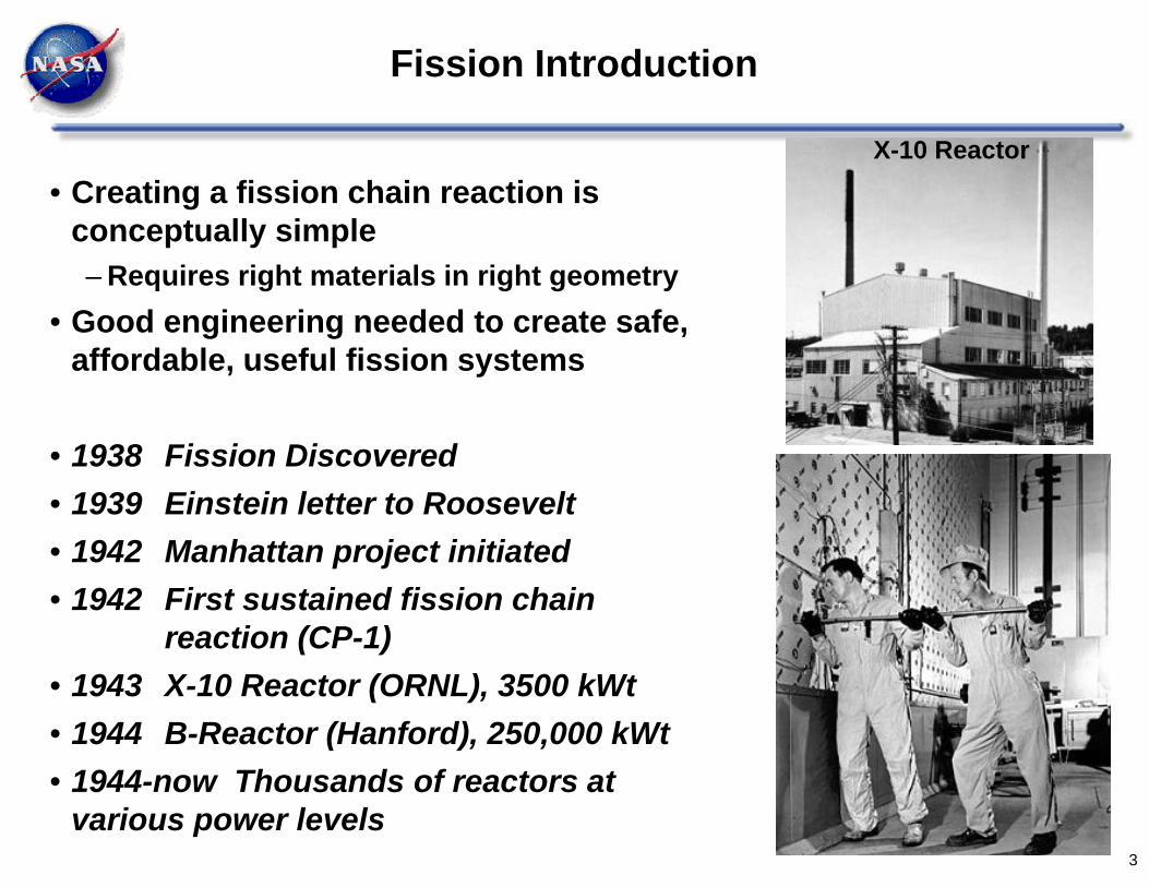
• Creating a fission chain reaction is conceptually simple– Requires right materials in right geometry
• Good engineering needed to create safe, affordable, useful fission systems
• 1938 Fission Discovered• 1939 Einstein letter to Roosevelt• 1942 Manhattan project initiated• 1942 First sustained fission chain
reaction (CP-1)• 1943 X-10 Reactor (ORNL), 3500 kWt• 1944 B-Reactor (Hanford), 250,000 kWt• 1944-now Thousands of reactors at
various power levels
X-10 Reactor
4
Fission is Highly Versatile with Many Applications
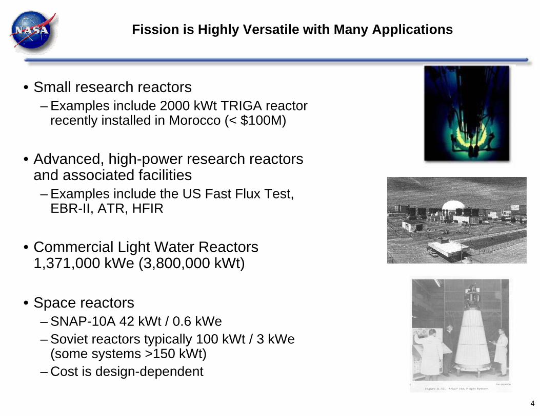
• Small research reactors– Examples include 2000 kWt TRIGA reactor
recently installed in Morocco (< $100M)
• Advanced, high-power research reactors and associated facilities– Examples include the US Fast Flux Test,
EBR-II, ATR, HFIR
• Commercial Light Water Reactors 1,371,000 kWe (3,800,000 kWt)
• Space reactors– SNAP-10A 42 kWt / 0.6 kWe– Soviet reactors typically 100 kWt / 3 kWe
(some systems >150 kWt)– Cost is design-dependent

5
Fission is Highly Versatile with Many Applications (continued)
• Naval Reactors– Hundreds of submarines and surface ships
worldwide
• Production of medical and other isotopes
• Fission Surface Power– Safe, abundant, cost effective power on the
moon or Mars
• Nuclear Thermal Propulsion– Potential for fast, efficient transportation
throughout inner solar system
• Nuclear Electric Propulsion– Potential for efficient transportation throughout
solar system
• Highly advanced fission systems for solar system exploration
6
Typical Space Fission System Operation
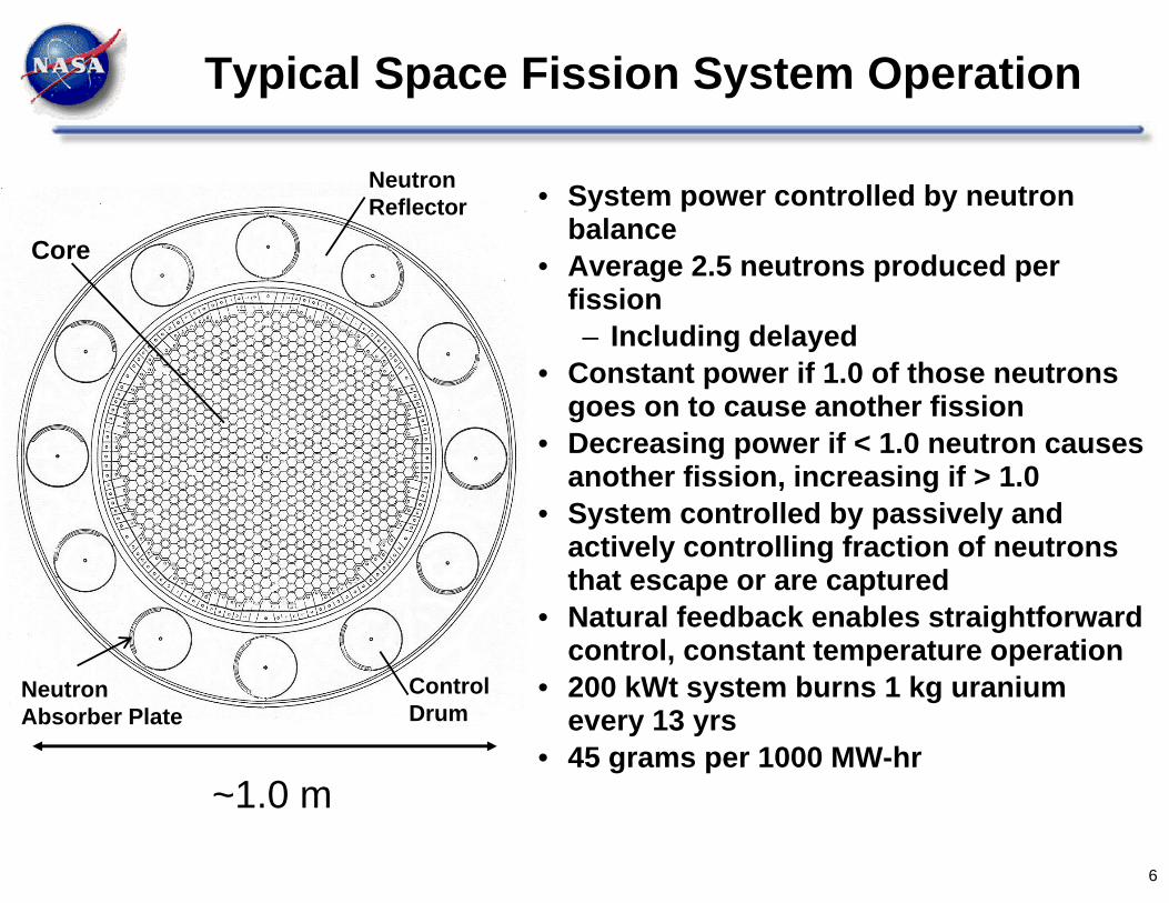
~1.0 m
• System power controlled by neutron balance
• Average 2.5 neutrons produced per fission– Including delayed
• Constant power if 1.0 of those neutrons goes on to cause another fission
• Decreasing power if < 1.0 neutron causes another fission, increasing if > 1.0
• System controlled by passively and actively controlling fraction of neutrons that escape or are captured
• Natural feedback enables straightforward control, constant temperature operation
• 200 kWt system burns 1 kg uranium every 13 yrs
• 45 grams per 1000 MW-hr
Core
Neutron Reflector
Control Drum
Neutron Absorber Plate

Time (not to scale)
STARTUP
k > 1
STEADY POWER PRODUCTION
INCREASE POWER LEVEL
SHUTDOWN
k = 1
STEADY POWER PRODUCTION
k > 1 k = 1
k < 1
Pow
er L
evel
(
Fis
sion
Rat
e
#N
eutr
ons)
Control of Reactor Conditions
k Multiplication Factor
Production RateLoss Rate N tln
N t
1 (subcritical, dN dt < 0)1 (critical, dN dt = 0)1 (supercritical, dN dt > 0)
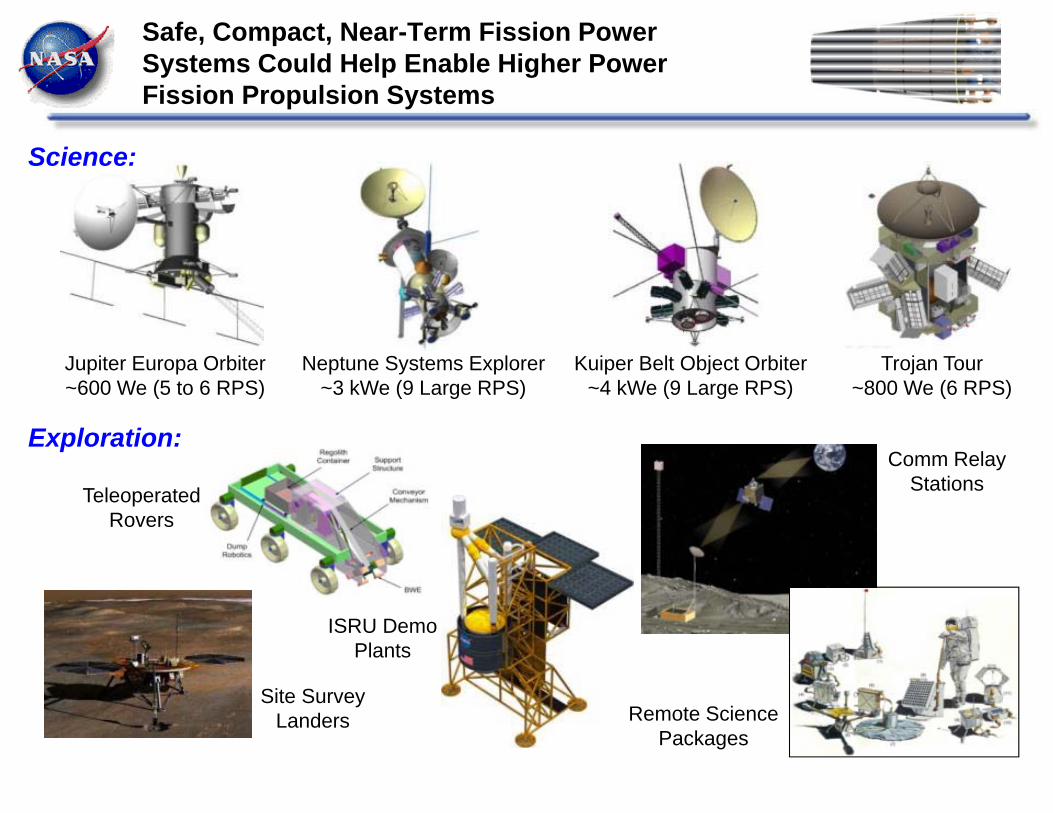
Safe, Compact, Near-Term Fission Power Systems Could Help Enable Higher Power Fission Propulsion Systems
Science:
Exploration:
Jupiter Europa Orbiter~600 We (5 to 6 RPS)
Neptune Systems Explorer~3 kWe (9 Large RPS)
Kuiper Belt Object Orbiter~4 kWe (9 Large RPS)
Trojan Tour~800 We (6 RPS)
Site SurveyLanders
TeleoperatedRovers
ISRU DemoPlants
Remote SciencePackages
Comm RelayStations
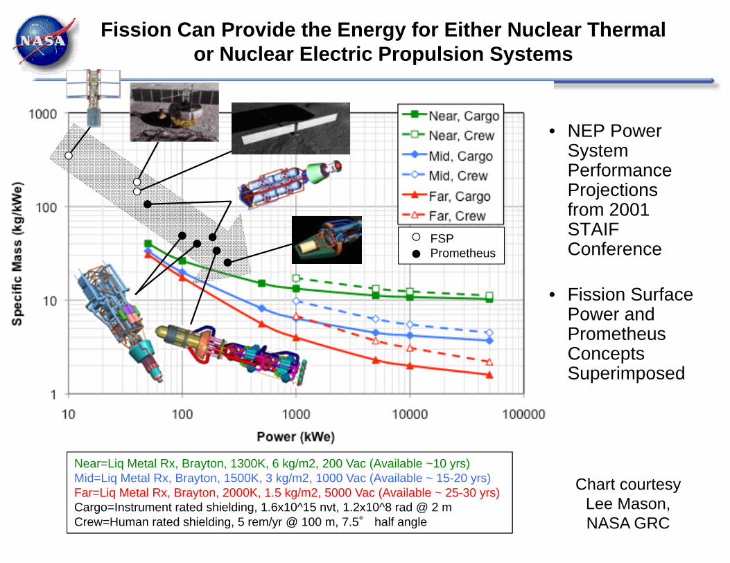
Fission Can Provide the Energy for Either Nuclear Thermal or Nuclear Electric Propulsion Systems
• NEP Power System Performance Projections from 2001 STAIF Conference
• Fission Surface Power and Prometheus Concepts Superimposed
Near=Liq Metal Rx, Brayton, 1300K, 6 kg/m2, 200 Vac (Available ~10 yrs)Mid=Liq Metal Rx, Brayton, 1500K, 3 kg/m2, 1000 Vac (Available ~ 15-20 yrs)Far=Liq Metal Rx, Brayton, 2000K, 1.5 kg/m2, 5000 Vac (Available ~ 25-30 yrs)Cargo=Instrument rated shielding, 1.6x10^15 nvt, 1.2x10^8 rad @ 2 mCrew=Human rated shielding, 5 rem/yr @ 100 m, 7.5° half angle
FSPPrometheus
Chart courtesy Lee Mason, NASA GRC
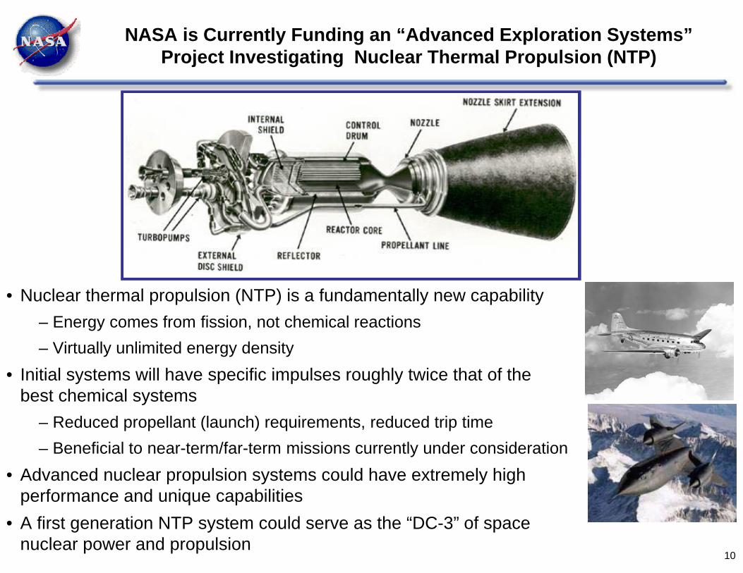
NASA is Currently Funding an “Advanced Exploration Systems” Project Investigating Nuclear Thermal Propulsion (NTP)
• Nuclear thermal propulsion (NTP) is a fundamentally new capability– Energy comes from fission, not chemical reactions– Virtually unlimited energy density
• Initial systems will have specific impulses roughly twice that of the best chemical systems
– Reduced propellant (launch) requirements, reduced trip time– Beneficial to near-term/far-term missions currently under consideration
• Advanced nuclear propulsion systems could have extremely high performance and unique capabilities
• A first generation NTP system could serve as the “DC-3” of space nuclear power and propulsion
10

11
Leverage the highly successful Rover/NERVA program (1955-1973) and more recent programs
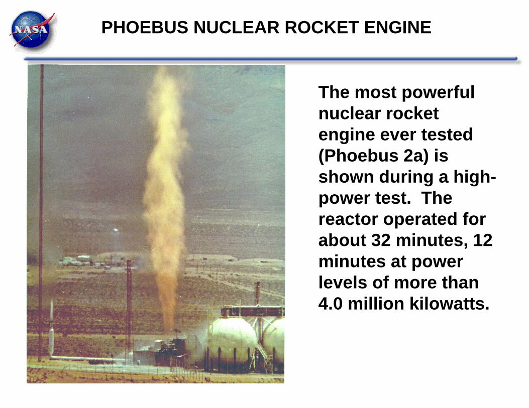
The most powerful nuclear rocket engine ever tested (Phoebus 2a) is shown during a high-power test. The reactor operated for about 32 minutes, 12 minutes at power levels of more than 4.0 million kilowatts.
PHOEBUS NUCLEAR ROCKET ENGINE
70 80 90 100 110 120 130 140 150 16010-4
10-3
10-2
10-1
1
10
Mass Number
Fiss
ion
Yiel
d (%
)
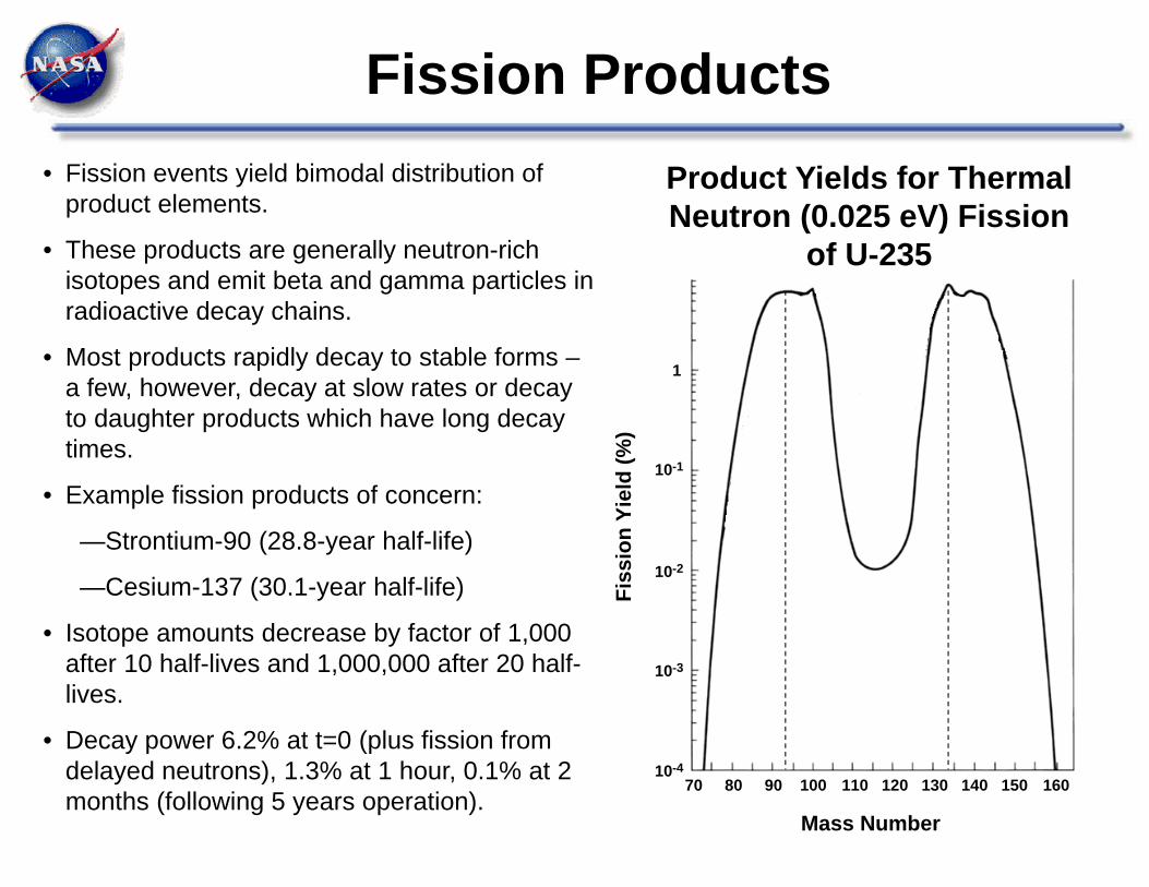
• Fission events yield bimodal distribution of product elements.
• These products are generally neutron-rich isotopes and emit beta and gamma particles in radioactive decay chains.
• Most products rapidly decay to stable forms –a few, however, decay at slow rates or decay to daughter products which have long decay times.
• Example fission products of concern:
—Strontium-90 (28.8-year half-life)
—Cesium-137 (30.1-year half-life)
• Isotope amounts decrease by factor of 1,000 after 10 half-lives and 1,000,000 after 20 half-lives.
• Decay power 6.2% at t=0 (plus fission from delayed neutrons), 1.3% at 1 hour, 0.1% at 2 months (following 5 years operation).
Product Yields for Thermal Neutron (0.025 eV) Fission
of U-235
Fission Products

Fission Products
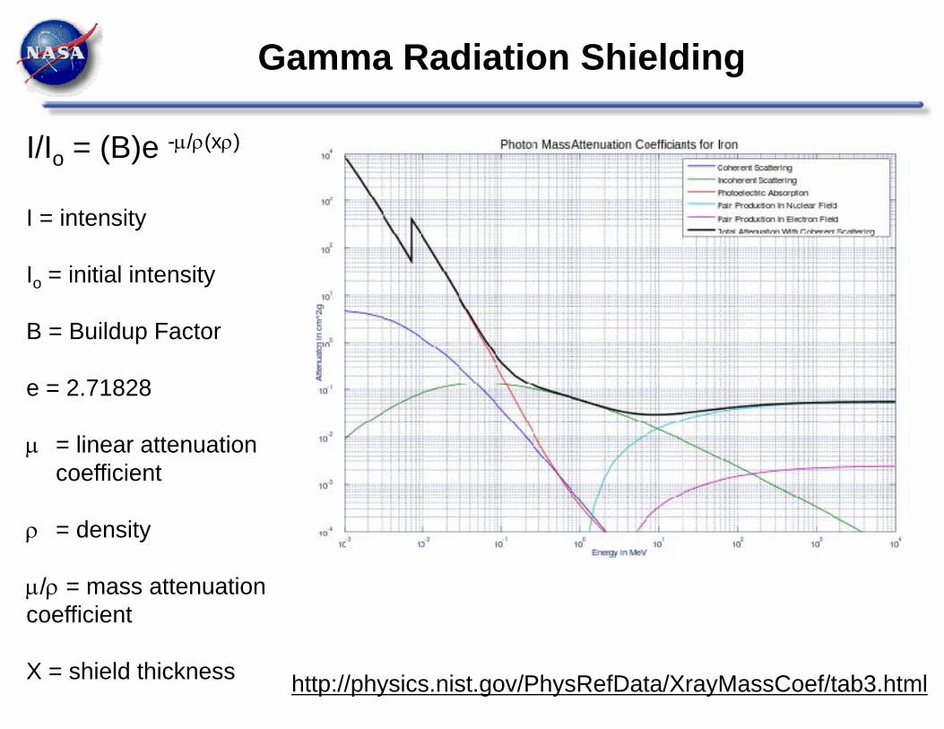
Gamma Radiation Shielding
I/Io = (B)e -/(x)
I = intensity
Io = initial intensity
B = Buildup Factor
e = 2.71828
= linear attenuation coefficient
= density
/ = mass attenuation coefficient
X = shield thickness http://physics.nist.gov/PhysRefData/XrayMassCoef/tab3.html
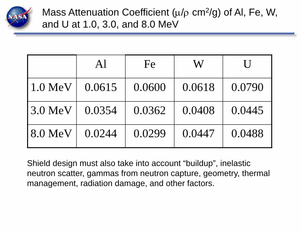
Mass Attenuation Coefficient (/ cm2/g) of Al, Fe, W, and U at 1.0, 3.0, and 8.0 MeV
Al Fe W U
1.0 MeV 0.0615 0.0600 0.0618 0.0790
3.0 MeV 0.0354 0.0362 0.0408 0.0445
8.0 MeV 0.0244 0.0299 0.0447 0.0488
Shield design must also take into account “buildup”, inelastic neutron scatter, gammas from neutron capture, geometry, thermal management, radiation damage, and other factors.
Neutron Radiation Shielding
Use hydrogenous material to slow neutrons.
Optimal Design – Avoid Capture Gammas, Gammas From Inelastic Scatter
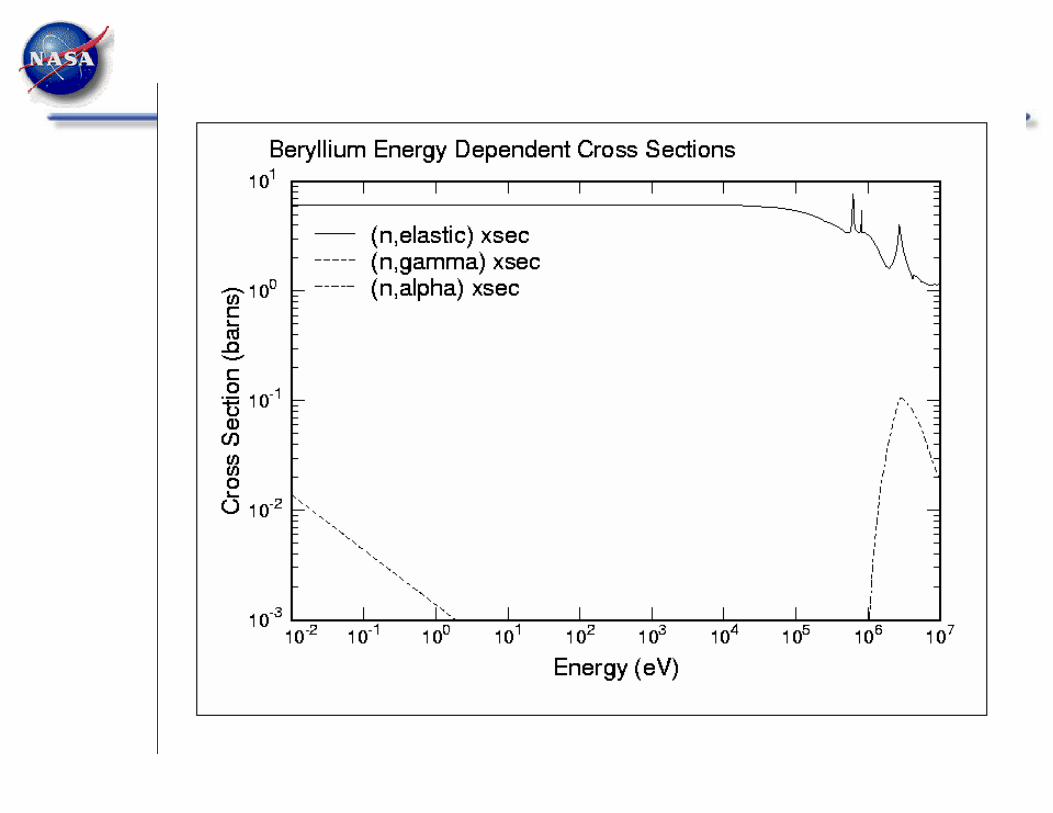
6Li and 10B capture neutrons with no significant gamma radiation released.
Water is a great neutron shield, borated water a little better still!
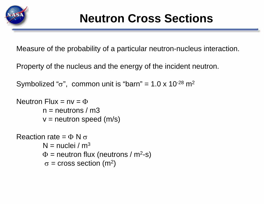
Neutron Cross Sections
Measure of the probability of a particular neutron-nucleus interaction.
Property of the nucleus and the energy of the incident neutron.
Symbolized “”, common unit is “barn” = 1.0 x 10⁻²⁸ m2
Neutron Flux = nv = n = neutrons / m3v = neutron speed (m/s)
Reaction rate = N N = nuclei / m3
= neutron flux (neutrons / m2-s) = cross section (m2)
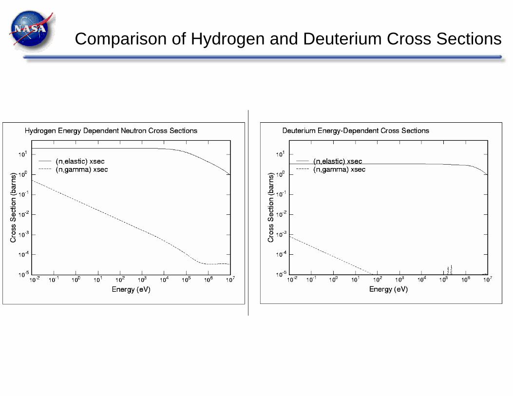
Comparison of Hydrogen and Deuterium Cross Sections


5.3 m
24.8 m 23.1 m 21.2 m
11.2 m
4 crewTransHab
Primary PVAs
Small PVA(1 of 4) Long Saddle Truss
7.6 m
Propulsion Stage
CommunicationsAntenna (1 of 2)
3 – 15klbfNTR Engines
LH2 Drop Tank
16.0 m
Lunar Habitat Lander
Orion MPCV
Short Saddle Truss,Transfer Tunnel
and MMSEV
Lunar Lander & Orion MPCV
26.1 m
25.3 m
25.6 m
25.6 m
ASV 2000 SG344:• 4 crew• 3 – 15 klbf NTRs• 7.6 m LH2 tanks• IMLEO ~178.7 t• Max Lift ~67 t
Lunar Cargo:• 57 t Habitat Lander• 3 – 15 klbf NTRs• 7.6 m LH2 tanks• IMLEO ~198 t• Max Lift ~69.3 t
Lunar Landing:• 4 crew• 34.5 t Lunar Lander• 3 – 15 klbf NTRs• 7.6 m LH2 tanks• IMLEO ~197.5 t• Max Lift ~72.8 t
NTR Transfer Vehicles for Reusable NEA, Lunar Cargo and Crewed Landing Missions using ~70 t-class SLS
(Courtesy Stan Borowski, NASA GRC)
23

Configuration 1 Applications:• Fast Conjunction Mars Landing Missions – Expendable• “1-yr” Round Trip to Large NEAs 1991 JW (2027) and
Apophis (2028) – Reusable• Propulsion Stage & Saddle Truss / Drop Tank Assembly can also be used as:
• Earth Return Vehicle (ERV) / propellant tanker in “Split Mars Mission” Mode – Expendable
• Cargo Transfer Vehicle supporting a Lunar Base – Reusable
Configuration 2 Applications:• Fast Conjunction Mars Landing Missions – Reusable
• 2033 Mars Orbital Mission545 Day Round Trip Time with60 Days at Mars – Expendable
• Cargo & Crew Delivery to Lunar Base – Reusable
MMSEV replaces consumables container
for NEA missions
Configuration 3 Applications:• Fast Conjunction Mars Landing Missions – Reusable or Expendable
• 2033 Mars Orbital Mission545 Day Round Trip Time with60 Days at Mars – Reusable
• Some LEO Assembly Required – Attachment of Drop Tanks
• Additional HLV Launches
Options for Increasing Thrust:• Add 4th Engine, or• Transition to LANTR Engines– NTRs with O2 “Afterburners”
3 – 25 klbfNTRs
Transition to “Star Truss”with 2 – 4 Drop Tanks to
Increase Propellant Capacity
“Saddle Truss” / LH2Drop Tank Assembly
“In-Line” LH2 Tank
Crewed Payload
Common NTR “Core” Propulsion Stages
Growth Paths Identified using Modular Components to Increase Vehicle LH2 Capacity & Mission Applications
(Courtesy Stan Borowski, NASA GRC)
24

Notional NCPS Mission -- 2033 600 day Mars Piloted StackCore Stage, In-line Tank, & Star Truss w/ (2) LH2 Drop Tanks
(Courtesy Stan Borowski, NASA GRC)
Three 25.1 klbfNTRs
NTP Transfer Vehicle Description:
• # Engines / Type: 3 / NERVA-derived• Engine Thrust: 25.1 klbf (Pewee-class)• Propellant: LH2• Specific Impulse, Isp: 900 sec • Cooldown LH2: 3%• Tank Material: Aluminum-Lithium• Tank Ullage: 3%• Tank Trap Residuals: 2%• Truss Material: Graphite Epoxy Composite• RCS Propellants: NTO / MMH• # RCS Thruster Isp: 335 sec (AMBR Isp)• Passive TPS: 1” SOFI + 60 layer MLI• Active CFM: ZBO Brayton Cryo-cooler• I/F Structure: Stage / Truss Docking
Adaptor w/ Fluid Transfer
Core Propulsion
Stage
Star Truss & (4) LH2 Drop Tank Option
NTP system consists of 3 elements: 1) core propulsion stage, 2) in-line tank, and 3) integrated star truss and dual drop tank assembly that connects the propulsion stack to the crewed payload element for Mars 2033 mission. Each 100t element is delivered on an SLS LV (178.35.01, 10m O.D.x 25.2 m cyl. §) to LEO -50 x 220 nmi, then onboard RCS provides circ burn to 407 km orbit. The core stage uses three NERVA-derived 25.1 klbf engines. It also includes RCS, avionics, power, long-duration CFM hardware (e.g., COLDEST design, ZBO cryo-coolers) and AR&D capability. The star truss uses Gr/Ep composite material & the LH2 drop tanks use a passive TPS. Interface structure includes fluid transfer, electrical, and communications lines.
Design Constraints / Parameters:
• 6 Crew• Outbound time: 183 days (nom.)• Stay time: 60 days (nom.)• Return time: 357 days (nom.)• 1% Performance Margin on all burns• TMI Gravity Losses: 265 m/s total, f(T/W0)• Pre-mission RCS Vs: 181 m/s (4 burns/stage)• RCS MidCrs. Cor. Vs: 65 m/s (in & outbnd)• Jettison Both Drop Tanks After TMI-1• Jettison Tunnel, Can & Waste Prior to TEI
Mission Constraints / Parameters:
In-line Tank Payload: DSH,CEV, Food, Tunnel, etc.
Inline (2) drop payload corePower Level (kW) 5.25 44.75 7.07
Tank Diameter (m) 8.90 8.90 8.90Tank Length (m) 19.30 13.58 17.10Truss length (m) 19 12
Liquid LH2 72.18 96.29 62.90Total Foodstores 8.01
6 Crew 0.79Dry weight 17.67 19.30 36.41TransHab+Crew Science 34.649Samples 0.25CEV 10.10
Total Launch Element Mass (mt) 100.50 121.48 67.93 101.94RCS Total Propellant 18.66Total Launched Mass 391.84 mt
V (m/s)
Burn Time (min)
1st perigee TMI + g‐loss 2380 39.42nd perigee TMI 1445 17.8
MOC 1470 15TEI 3080 23.5
8375 95.7
Notional Example of Human Mars Mission 25
26
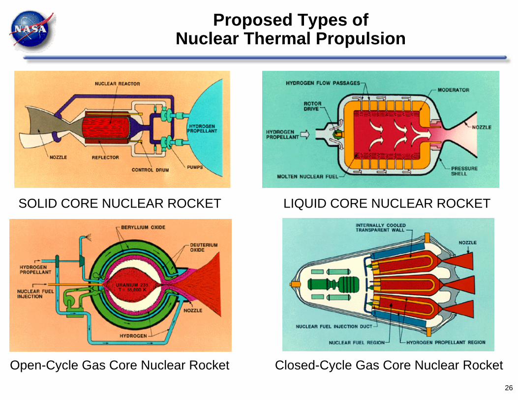
Proposed Types of Nuclear Thermal Propulsion
LIQUID CORE NUCLEAR ROCKETSOLID CORE NUCLEAR ROCKET
Open-Cycle Gas Core Nuclear Rocket Closed-Cycle Gas Core Nuclear Rocket
Future Plans / Path Forward
• Space fission power and propulsion are game changing technologies for space exploration
• The NASA Nuclear Thermal Propulsion (NTP) project has 1 to 3 years to demonstrate the viability and affordability of NTP
• Participation is encouraged. Please feel free to contact the NTP project with interest or ideas ([email protected])
27


![PART 2 POWER AND PROPULSION CYCLES - MIT ... PART 2 – POWER AND PROPULSION CYCLES 2A – Gas Power and Propulsion Cycles [SB&VW - 11.8, 11.9, 11.10, 11.11, 11.12, 11.13, 11.14] In](https://static.fdocuments.in/doc/165x107/5b0932437f8b9a51508cf3d1/part-2-power-and-propulsion-cycles-mit-part-2-power-and-propulsion-cycles.jpg)


