Space Air Diffusion I - ibse.hkibse.hk/MEBS6008/mebs6008_1617_05-space_air_diffusion_I.pdf ·...
72
Space Air Diffusion I Ir. Dr. Sam C. M. Hui Visiting Assistant Professor Department of Mechanical Engineering The University of Hong Kong E-mail: [email protected] MEBS6008 Environmental Services II http://me.hku.hk/bse/MEBS6008/ Aug 2016
Transcript of Space Air Diffusion I - ibse.hkibse.hk/MEBS6008/mebs6008_1617_05-space_air_diffusion_I.pdf ·...

Space Air Diffusion I
Ir. Dr. Sam C. M. HuiVisiting Assistant Professor
Department of Mechanical EngineeringThe University of Hong Kong
E-mail: [email protected]
MEBS6008 Environmental Services IIhttp://me.hku.hk/bse/MEBS6008/
Aug 2016

Contents
• Basic Principles
• Air Jets
• Outlets and Inlets
• Mixing Flow

Basic Principles
• Objective of space air diffusion
• Evenly distribute conditioned & outdoor air to provide healthy & comfortable indoor environment, or appropriate environment for process, at optimum cost
• Last process of air conditioning
• Take place entirely within conditioned space
• Directly affect the occupants, but it is difficult to trace & quantify

Basic Principles
• Important considerations:
• Thermal comfort (temp., humidity, air velocity)
• Comfort conditions, local variations
• Indoor air quality
• Airborne pollutants
• Ventilation effects
• Noise control
• Noise criteria, sound attentuation
• Occupied zone: 1.8 m from floor

Occupiedzone
(Source: Rock, B. A. and Zhu, D., 2002. Designer’s Guide to Ceiling-based Air Diffusion.)

Basic Principles
• Draft & effective draft temperature
• Draft: unwanted local cooling of human body caused by air movement & lower space air temp.
• Turbulence intensity, Itur = σv / vm
• σv = standard deviation of air velocity fluctuation (m/s)
• vm = mean air velocity (m/s)
• Effective draft temperature: combines effects of uneven space air temp. & air movement
• θ = Tx – Tr – a (vx – vrm)
Thermal Comfort

(Source: Wang, S. K., 2001. Handbook of Air Conditioning and Refrigeration)

Basic Principles
• Air diffusion performance index (ADPI)
• ADPI = (Nθ x 100) / N• θ: effective draft temperature
• Nθ: number of points measured in occupied zone in which -1.7 oC < θ <1.1 oC
• N : total number of points measured in occupied zone
• Higher the ADPI, higher % of occupants who feel comfortable
• ADPI is useful for cooling mode operation
• For heating mode, temperature gradient ٪ 2 points may be a better indicator of thermal comfort (< 2.8 oC typical)

Basic Principles
• Air exchange rate• = Volume flow rate / interior volume
• Unit: L/s or air change per hour (ACH)
• May consider outside air, or supply air
• Time constant (τ)• Inverse of air exchange rate
• Air diffusion effectiveness• Perfectly mixing, perfectly displacing
• Degree of effectiveness of air diffusion
Basic Principles
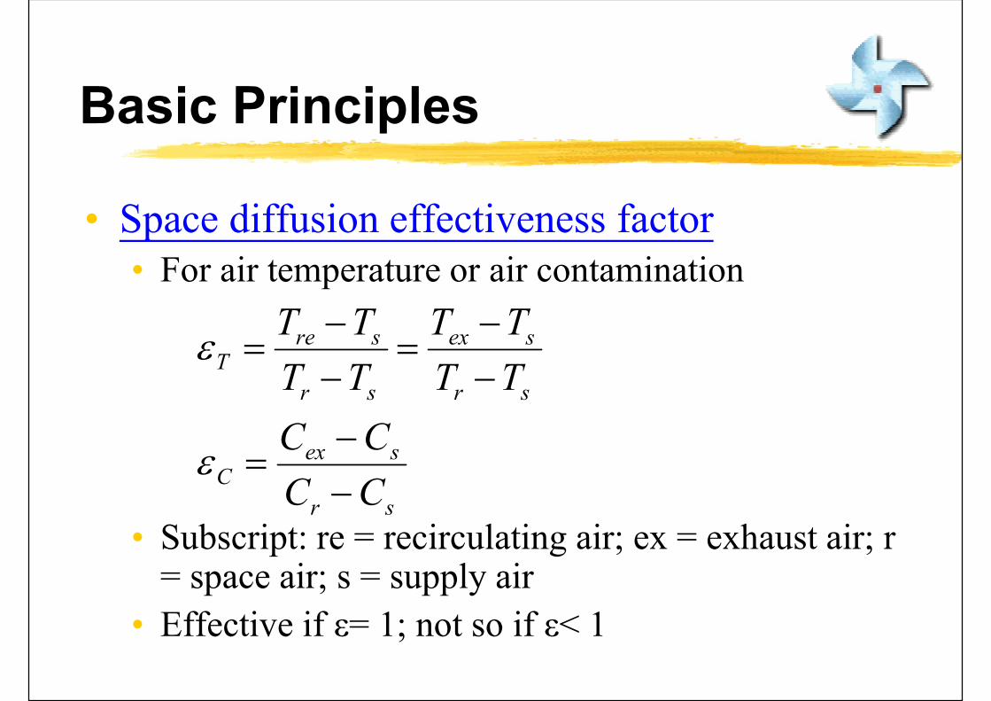
• Space diffusion effectiveness factor• For air temperature or air contamination
• Subscript: re = recirculating air; ex = exhaust air; r = space air; s = supply air
• Effective if ε= 1; not so if ε< 1
sr
sexC
sr
sex
sr
sreT
CC
CC
TT
TT
TT
TT

Basic Principles
• Ventilation effectiveness
• Air system’s ability to remove internally generated contaminants from a zone, space or building
• Age of air θage (in minutes or hours)
• Time period that outdoor ventilation air has been in a zone, space or building
• Evaluated using tracer gas method
• The “youngest” air = freshest air
Basic Principles
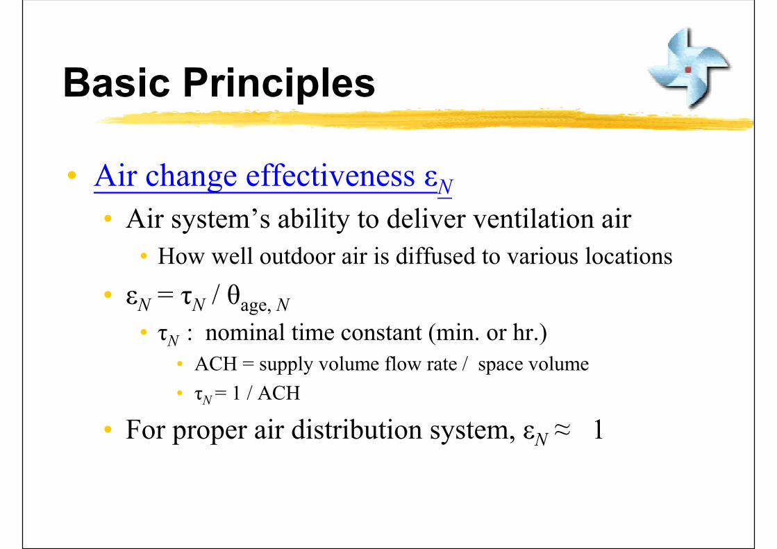
• Air change effectiveness εN
• Air system’s ability to deliver ventilation air
• How well outdoor air is diffused to various locations
• εN = τN / θage, N
• τN : nominal time constant (min. or hr.)• ACH = supply volume flow rate / space volume
• τN = 1 / ACH
• For proper air distribution system, εN ≈ 1
Air Jets
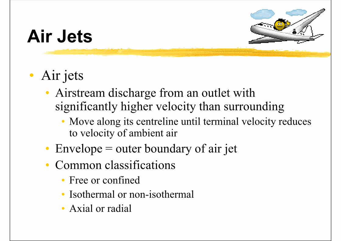
• Air jets• Airstream discharge from an outlet with
significantly higher velocity than surrounding• Move along its centreline until terminal velocity reduces
to velocity of ambient air
• Envelope = outer boundary of air jet
• Common classifications• Free or confined
• Isothermal or non-isothermal
• Axial or radial

Air Jets
• Air jets
• Free air jet: envelope not confined by enclosure
• Confined air jet: envelope confined by ceiling, floor, walls, windows, furniture, etc
• Air jet approaches a free air jet if √Ar / Do > 50• Ar = cross-sectional area of the enclosure perpendicular to the
air jet centreline
• Do = diameter or circular equivalent of supply outlet
• Isothermal jets: whose temperature is equal to the ambient air (c.f.: non-isothermal jets)

Four zones of a free, isothermal, axial air jet
(Source: Wang, S. K., 2001. Handbook of Air Conditioning and Refrigeration)

Air Jets
• Free isothermal jets• Core zone
• Centreline velocity remains unchanged• Extends about 4 Do from the outlet
• Transition zone• Centreline velocity decreases inversely w/ square root of distance
from outlet• Extends about 8 Do from the outlet
• Main zone• Turbulent flow is fully developed• Extends about 25-100 Do from the outlet
• Terminal zone• Max. air velocity decreases rapidly to less than 0.25 m/s
(Source: Rock, B. A. and Zhu, D., 2002. Designer’s Guide to Ceiling-based Air Diffusion.)

Air Jets
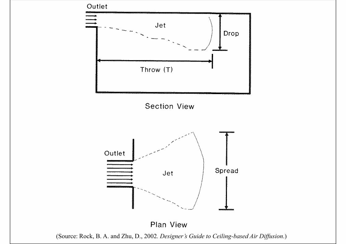
• Throw, Tv (m)
• Horizontal or vertical axial distance from outlet to a cross-sectional plane where max. velocity of airstream at the terminal zone has been reduced to 0.25, 0.5, or 0.75 m/s
fadct
sv
RCAv
VKT
max,
'
K’ = centreline velocity constantVs = supply volume flow ratevt,max = max. velocity at terminal zoneAc = core area of outletCd = discharge coefficientRfa = ratio of free area to gross area
Air Jets
• Entrainment ratio
• Ratio of volume flow rate to the total air at a specific cross-sectional plane of the air jet to volume flow rate of the supply air discharged from outlet (primary air)
• Total air = sum of supply air and induced air
• Proportional to the distance or square root of the distance from outlet

Air Jets
• Characteristic length, L
• Horizontal distance from outlet to the nearest vertical opposite wall, or to the midplane between 2 outlets in the direction, OR the distance to the closest intersection of air jets
• Ratio of Tv/L is related to ADPI of various supply outlets and has been used a parameter in space diffusion design
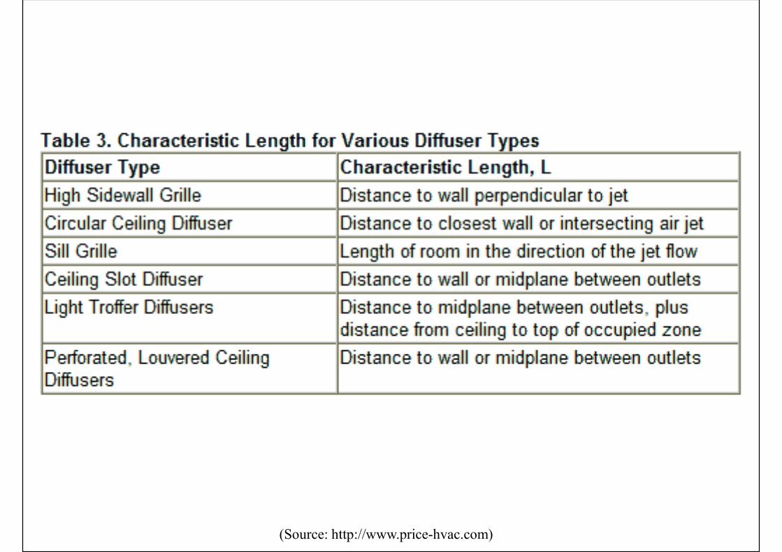
(Source: http://www.price-hvac.com)
Air Jets
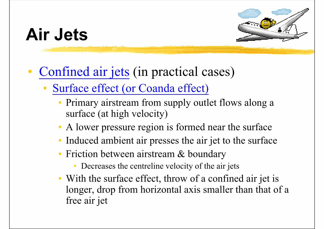
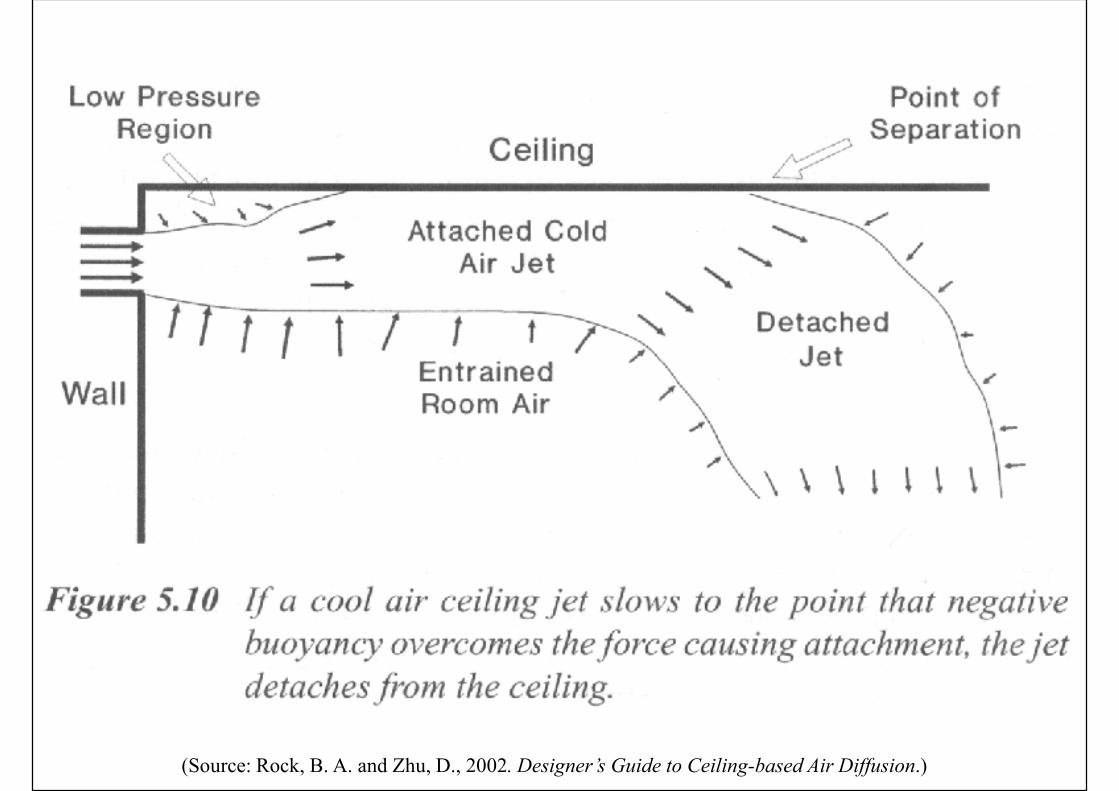
• Confined air jets (in practical cases)• Surface effect (or Coanda effect)
• Primary airstream from supply outlet flows along a surface (at high velocity)
• A lower pressure region is formed near the surface
• Induced ambient air presses the air jet to the surface
• Friction between airstream & boundary• Decreases the centreline velocity of the air jets
• With the surface effect, throw of a confined air jet is longer, drop from horizontal axis smaller than that of a free air jet

Surface effect (or Coanda effect)
(Source: Wang, S. K., 2001. Handbook of Air Conditioning and Refrigeration)

(Source: Rock, B. A. and Zhu, D., 2002. Designer’s Guide to Ceiling-based Air Diffusion.)
Air Jets
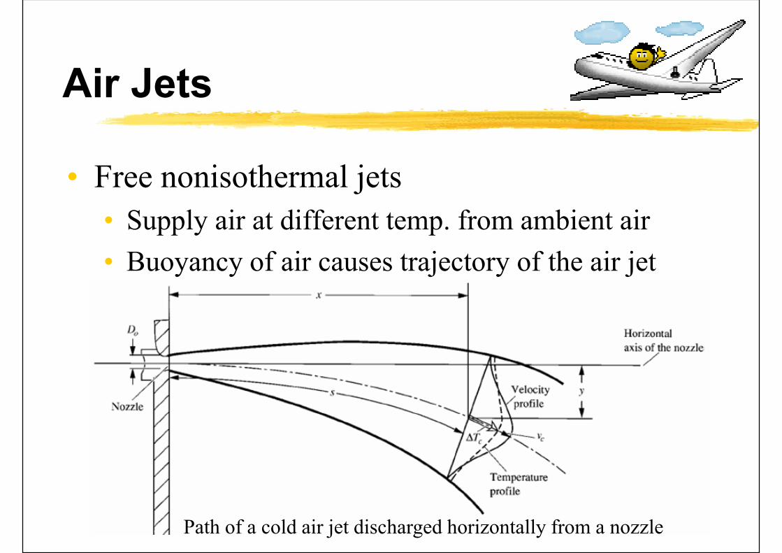
• Free nonisothermal jets
• Supply air at different temp. from ambient air
• Buoyancy of air causes trajectory of the air jet
Path of a cold air jet discharged horizontally from a nozzle

(Source: Rock, B. A. and Zhu, D., 2002. Designer’s Guide to Ceiling-based Air Diffusion.)
(Source: Rock, B. A. and Zhu, D., 2002. Designer’s Guide to Ceiling-based Air Diffusion.)

(Source: Rock, B. A. and Zhu, D., 2002. Designer’s Guide to Ceiling-based Air Diffusion.)
Primaryair
Secondaryair
Total air

(Source: Rock, B. A. and Zhu, D., 2002. Designer’s Guide to Ceiling-based Air Diffusion.)

(Source: Rock, B. A. and Zhu, D., 2002. Designer’s Guide to Ceiling-based Air Diffusion.)

(Source: Rock, B. A. and Zhu, D., 2002. Designer’s Guide to Ceiling-based Air Diffusion.)

(Source: Rock, B. A. and Zhu, D., 2002. Designer’s Guide to Ceiling-based Air Diffusion.)

Outlets and Inlets
• Supply outlets
• Grilles and registers
• Ceiling diffusers
• Slot diffusers
• Nozzles
• Return & exhaust inlets
• Light troffer diffuser & troffer-diffuser slot
• Design issues: architectural setup, airflow pattern needed, indoor requirements, load conditions

Supply grille and register
(Source: Wang, S. K., 2001. Handbook of Air Conditioning and Refrigeration)

Airflow patterns of high sidewall supply grilles
(Source: ASHRAE Handbook Fundamentals 2001)

Outlets and Inlets
• Performance data of grilles and registers
• Core size or core area
• Volume flow rate
• Air velocity
• Total pressure loss
• Throw at various terminal velocities
• Noise criteria curve

Ceiling diffusers
Square & rectangular
Removable inner-corePerforated ceiling diffuser
(Source: Wang, S. K., 2001. Handbook of Air Conditioning and Refrigeration)

Slot diffusers
(Source: Wang, S. K., 2001. Handbook of Air Conditioning and Refrigeration)

Round nozzle Nozzle diffuser
(Source: Wang, S. K., 2001. Handbook of Air Conditioning and Refrigeration)

Accessories for supply outlets
(Source: Wang, S. K., 2001. Handbook of Air Conditioning and Refrigeration)

Return grilles and registers(Source: Wang, S. K., 2001. Handbook of Air Conditioning and Refrigeration)
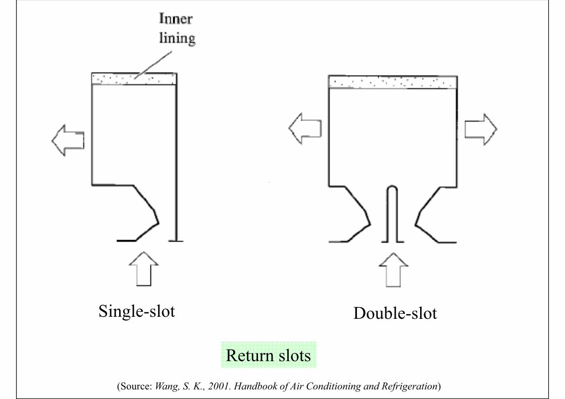
Return slots
Single-slot Double-slot
(Source: Wang, S. K., 2001. Handbook of Air Conditioning and Refrigeration)

Light troffer, slot diffuser and return slot combination(Source: Wang, S. K., 2001. Handbook of Air Conditioning and Refrigeration)
Mixing Flow
• Four typical airflow patterns
• Mixing flow (most common)
• Displacement flow
• Projecting flow
• Upward flow
• Also, task or personal air-conditioning systems

Mixing Flow
• Principles of mixing flow systems• Conditioned air discharged from outlets at high
velocity
• Conditioned air temperature may be above, below or equal to room air, depending on cooling/heating
• Supply air mixed with room air by entrainment
• Occupied zone is dominated by induced recirculating flow
• Creates relatively uniform air velocity, temperature, humidity, and air quality

Mixing Flow
• Characteristics of mixing flow
• Induction of space air into the air jet
• Reverse airstream (induced) in occupied zone
• Minimise the stagnant area in occupied zone
• Air velocity of stagnant area < 0.1 m/s
• Types & locations of return & exhaust inlets
• Does not significantly affect airflow pattern
• Does affect the thermal effectiveness factor εT

Mixing Flow
• Outlet classification (from ASHRAE)
• Group A. mounted in or near ceiling that discharge air horizontally
• Group B. mounted in or near floor that discharge air vertically in a non-spreading jet
• Group C. mounted in or near floor that discharge air vertically in a spreading jet
• Group D. mounted in or near floor that discharge air horizontally
• Group E. mounted in or near ceiling that project primary air vertically

(Source: ASHRAE Handbook Fundamentals 2001)
Group A Outlets

(Source: ASHRAE Handbook Fundamentals 2001)
Group B Outlets

(Source: ASHRAE Handbook Fundamentals 2001)
Group C Outlets

(Source: ASHRAE Handbook Fundamentals 2001)
Group D Outlets

(Source: ASHRAE Handbook Fundamentals 2001)
Group E Outlets

Mixing Flow
• Common types & locations of outlets• High side outlets
• Ceiling diffusers
• Slot diffusers
• Sill and floor outlets
• Outlets from stratified mixing flow
• Key questions• Will the air jet enter the occupied zone?
• Will stagnant zone be formed?
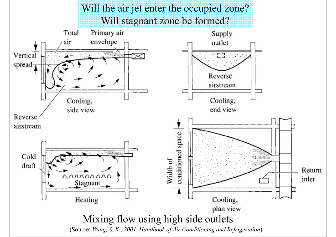
Mixing flow using high side outlets
Will the air jet enter the occupied zone?Will stagnant zone be formed?
(Source: Wang, S. K., 2001. Handbook of Air Conditioning and Refrigeration)

Mixing flow using ceiling diffusers(Source: Wang, S. K., 2001. Handbook of Air Conditioning and Refrigeration)

Mixing flow using slot diffusers
(heating)
(Source: Wang, S. K., 2001. Handbook of Air Conditioning and Refrigeration)

Mixing flow using sill outlet(Source: Wang, S. K., 2001. Handbook of Air Conditioning and Refrigeration)
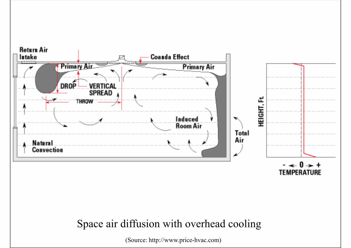
Space air diffusion with overhead cooling
(Source: http://www.price-hvac.com)

Space air diffusion with overhead heating
(Source: http://www.price-hvac.com)
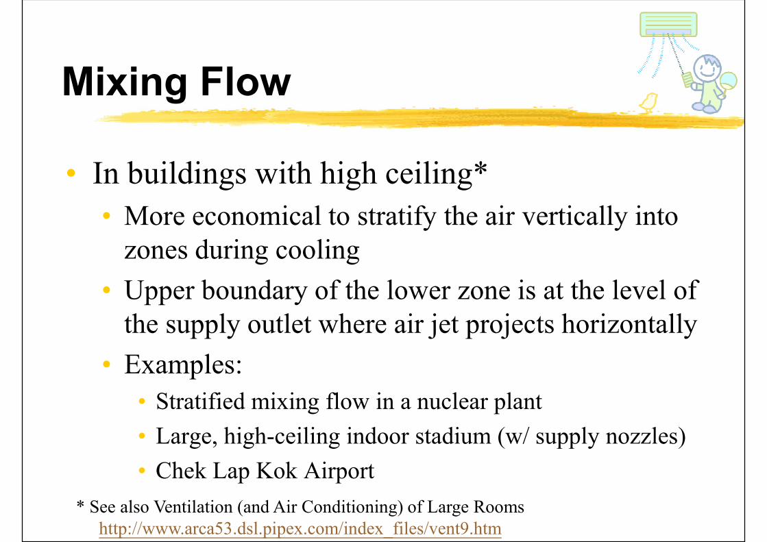
Mixing Flow
• In buildings with high ceiling*
• More economical to stratify the air vertically into zones during cooling
• Upper boundary of the lower zone is at the level of the supply outlet where air jet projects horizontally
• Examples:
• Stratified mixing flow in a nuclear plant
• Large, high-ceiling indoor stadium (w/ supply nozzles)
• Chek Lap Kok Airport
* See also Ventilation (and Air Conditioning) of Large Roomshttp://www.arca53.dsl.pipex.com/index_files/vent9.htm

Stratified mixing flow in a nuclear facility
During cooling During heating
(Source: Wang, S. K., 2001. Handbook of Air Conditioning and Refrigeration)

Stratified mixing flow in a large indoor stadium using supply nozzles
(Source: Wang, S. K., 2001. Handbook of Air Conditioning and Refrigeration)

Hong Kong International Airport

Mixing Flow
• Characteristics of stratified mixing flow• Convective heat transfer from hot roof is blocked
• Cooling loads in lower zone is offset by supply air
• Radiant heat from roof, wall & lights in upper zone enters the occupied zone and becomes cooling load
• Although supply airflow rate & temp. affect the throw & drop of the air jet, the induced recirculating airflow patterns in upper & lower zones remain the same
• Height of supply air jet determines upper boundary of the lower zone
• Location of return inlets influences cooling load only when they are located in the upper zone

Mixing Flow
• Design & selection method
• Review the form & use of the space, and determine if cooling or heating will be provided
• Determine the amounts of airflow rates
• Decide location for equipment
• Obtain & review equipment catalogues (find acceptable styles & models of air terminals)
• Lay out rough locations for air terminals
• Select specific models & sizes
Mixing Flow
• Design & selection method (cont’d)
• Check performance criteria (patterns, throws, sound levels, pressure drops)
• Relocate, reselect, recheck if needed
• Select any terminal boxes, size & lay out branch ductwork
• Prepare schedules, drawings & specifications
• Coordinate with other consultants (e.g. architect, interior designer)
Mixing Flow
• Select type of supply outlet
• Requirements of indoor environmental control
• Such as precise air movement & air temperature
• Shape, size, and ceiling height of the building
• Surface effect
• Volume flow per unit floor area
• Determine the number of outlets
• Appearance
• Cost
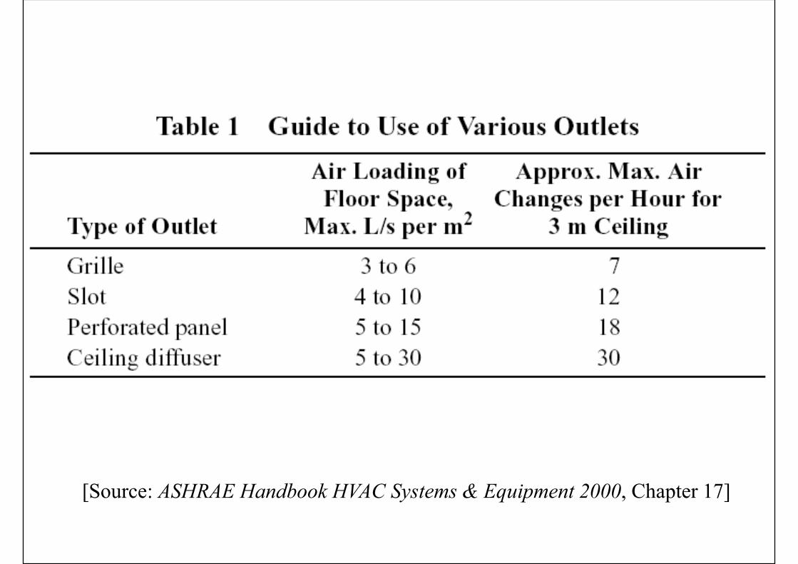
[Source: ASHRAE Handbook HVAC Systems & Equipment 2000, Chapter 17]

[Source: ASHRAE Handbook
Fundamentals 2001, Chapter 32]

Mixing Flow
• Select & check the specific supply outlet
• Major parameters
• Sound level• Combined sound level shall be at least 3 dB lower than the
recommended NC criteria
• Typical air veolcities: 2.5 to 6.25 m/s
• Drop of cold air jet• Will cold air jet enter the occupied zone?
• Total pressure loss• Typically, total pressure loss shall be lower than 50 Pa

Mixing Flow
• Determination of the final layout is often an iteration process
• Some good practices for return inlets:• If a ceiling plenum is used as return plenum, return
inlets shall be located outside supply air jet, above return airstream, or near a concentrated heat source
• Recommended face velocities for return inlets:• Above occupied zone: 4 to 5 m/s
• Within occupied zone: 2 to 3 m/s
• Door louvres: 1.5 to 2.5 m/s

Further Reading
• Price HVAC: Training Modules [http://www.priceindustries.com/resources/type/videos/training-modules]
• Basics of HVAC (10:57)
• Comfort Criteria (9:58)
• Space Air Diffusion (8:35)
• Air Outlet Selection (28:08)
• Displacement Ventilation (33:15)
• Underfloor Air Distribution (39:55)