
SP43
352
-
Upload
sourabhadike -
Category
Documents
-
view
96 -
download
3
Transcript of SP43

HANDBOOK ON STRUCTURES WITH i
REINFORCED CONCRETE PORTAL FRAMES (WITHOUT CRANES)
BUREAU OFINDIANSTANDARDS MANAKBHAVAN,gBAHADURSHAHZAFARMARG
NEWDELHI 110002
SP 43 (S & T) : 1987
FIRST PUBLISHED JANUARY 1990
0 BUREAU OF INDIAN STANDARDS
UDC 624.012-45 (021)
ISBN 81-7061-025-7
PRICE Rs 380.00
PRINTED IN INDIA
AT BENGAL OFFSET WORKS, 33 5 KHAJOOR ROAD, KAROL BAGH, NEW DELHI 110 005
AND PUBLISHED BY
BUREAU OF INDIAN STANDARDS, NEW DELHI 110 002

SPECIAL COMMITTEE FOR IMPLEMENTATION OF SCIENCE AND TECHNOLOGY PROJECTS (SCIP)
Chairman
DR H. C. VISVESVARAYA Cb&nan & Director General
National Council for Cement and Building Materials - New Delhi *
Members Representing
SHRI V. RAO AIYANGARI
SHRIA. K. BANERJEE
SHRI J. D. CHATURVEDI
DIRECTOR
SHRI GURNAM SINGH
SHRI U. R. KURLEKAR
DR M. RAMAIAH
SHRI G. S. RAO SHRI A. CHAKRABORTY
(A ltemate)
Department of Science & Technology, New Delhi
Metallurgical and Engineering Consultants (India) Ltd, Ran&i
Planning Commission, New Delhi
Central Building Research Institute (CSIR), Roorkee
Ministry of Food and Civil Supplies (Finance Division)
Ministry of Food and Civil Supplies
Structural Engineermg Research Centre (CSIR), Madras
Central Public Works Department, New Delhi
SHRI T. S. RATNAM SHRI P. K. KALRA (Alternate)
Bureau of Public Enterprises, New Delhi
SHRI G. RAMAN (Member Secretary)
Bureau of Indian Standards, New Delhi

WORKING GROUP FOR PROJECT B -8
Mem hers Representing
SHRI k K. BANERJEE
SHRI D. S. DESAI
SHRI J. C. GANGULY
SHRI P. V. NAIK
DR M. RAMAIAH SHRI V. S. PARAMESWARAN (A Zternfzte)
Metallurgical & Engineering Consultants (India) Ltd, Ran&i
M. N. Dastur & Co Pvt Ltd, Calcutta
Braithwaite Burn & Jessop Construction Co Ltd, Calcutta
Richardson & Cruddas Ltd, Bombay
Struc@rral Engineering Research Centre (CSIR), Madras
SHRI A. RAMAKRISHNA SHRI S. SUBRAMANIAM (A Zternate)
Engineering Construction Corporation Ltd, Madras
SHRI G. S. RAO SHRI A. CHAKRABORTY
(A Zternate)
Central Public Works Department,‘New Delhi
DR P. SRINIVASA RAO Indian Institute of Technology, Madras ~ROF (DR) L. N. RAMAMURTHY
(A kern&e) i
SHRI T. S. RATNAM Bureau of Public Enterprises, New Delhi SHRI P. k. KALRA (AZternute) *
SHRI D. AJITHA SIMHA Bureau of Indian Standards, New Delhi
SHRI C. N. SRINIVASAN C. R. Narayana Rao Architects & Engineers, Madras
SHRI ASHOK TREHAN SHRI A. C. GUPTA (AZternate)
National Thermal Power Corporation Limited, New Delhi
DR H. C. VISVESVARAYA National Council for Cement and Building Materials, New Delhi
iV

FOREWORD
The Department of Science and Technology set up an Expert Group on Housing and Construction Technology in 1972. This Group carried out in depth studies in various areas of civil engineering and construction practices :bllowed in the country. During the preparation of the Fifth Five-Year Plan in 1975, the Group was assigned the task of producing a Science and Technology Plan for research, development and extension work in the sector of housing and construction technology. As a result of this and on the recommendation of the Department of Science and Technology, the Planning Commission approved the following two projects which are assigned to the Bureau of Indian Standards (BIS):
a) Project B-7 - Development Programme on Code Implementation for Building and Civil Engineering Construction; and
b) Z+oject B-8 - Typification of Industrial Structures.
BIS has set up a special committee (SUP) consisting of experts to advise and monitor the execution of these projects. A Working Group under SCIP oversees the work of Project B-8.
In a developing country like India, the capital outlay under each Five-Year Plan towards setting up of industries and consequently construction of industrial buildings is very high. It is, therefore, necessary that the various parameters of industrial buildings be standardized on broad norms so that it will be feasible to easily adopt prefabricated members, particularly where repetitive structures could be used.
The standardization of parameters for industries by itself wilI be, no doubt, a difficult task as it will not be possible to specify the requirements of each industry. The layout including height, will vary from industry to industry, for it depends on the process of mantiacture and end products. However, a little more detailed analysis of the requirements indicated that the problems may not be as difficult as it appears. Although it would not be possible to specify any constraint on the parameters, a broad norm can be given within which most industries could be accommodated.
The object of the Project B-8 is to typify at national level the common forms of industrial structures used in light and medium engineering industries, warehouses, workshops and process industries, and to obtain economical designs under these conditions. Even if an industrial complex is classified as heavy industry, it need not necessarily mean that alI the industrial structures coming within the complex should be heavy industrial structures and that many structures could be from the typified design.
The main objective of typification of industrial structures is to reduce the variety to the minimum and provide standard prefabricated designs so that the structures could be easily mass produced and made available to the user almost off the shelf. In doing so, there will be tremendous saving in time in putting up an industry into production and hence increased production. This would indirectly increase the overall economy to the country. This would also help in the orderly use of scarce materials like steel and cement. This would be of immense use to structural engineers as well, since it would relieve them to a large extent from the routine and repetitive calculations. Thus the engineer’s time could be used to look at more innovative and economical alternatives.
The project on typification of industrial structures involved the following three main tasks prior to preparation of typified designs:
a) TuskZ - Survey and classification of industrial structures into different types;
b) TuskZZ - Identification of industrial structures repeated a large number of times in the country, which are amenable for typification from the classified list prepared during task I; and
V

c) Task ZZZ - Specifying the elements of the industrial structures to be typified taking into consideration a number of parameters, such as structures with cranes and without cranes, span length, height, support conditions, slope of roof, wind and earthquake forces, spacing, field and shop connections, material (steel, reinforced concrete), etc.
The data regarding physical parameters like span, spacing, roof slope, column height, crane loading, etc, of existing structures has been obtained from several public sector enterprises through Bureau of Public Enterprises (BPE). Some information from private industries has also been collected by BIS.
The typified design for the following types of industrial structures in steel and reinforced concrete is envisaged to be brought out based on appropriate Indian Standards:
a) Steel Structures
1) Structures with steel roof trusses (with and without cranes) 2) Structures with steel kneebraced trusses (without cranes) 3) Structures with steel portal frames (without cranes) 4) Structures with steel portal frames (with cranes) 5) Structures with steel latice frames (without cranes)
b) Reinforced Concrete Structures
1) Structures with RCC roof trusses (with and without cranes) 2) Structures with RCC portal frames (without cranes) 3) Structures with RCC portal frames (with cranes)
In each case of structures with cranes, the maximum capacity of crane considered is limited to 20 tonnes, normal range in light industries.
This Handbook deals with typification of structures with RCC portal frames (without cranes). Typification includes analysis and design of RCC portal frames. The portal frame has been analyzed and designed for vertical and lateral loads (wind and‘earthquake forces) using the moment resisting portal frame action, with pinned_ and fured support alternatives. Adequate wind bracing along the length of the building should be provided to withstand the wind on end gable and drag force on the roof and walls. Since the design for this depends upon the length of the building, locations of the expansion joint, etc, the typified design of these bracings is not given in the Handbook. However, an illustrative example of bracing design has been included.
Some of the points to be noted regarding analysis and design of these structures are as. follows:-
a) The typified designs have been given for the following parameters:
Span lengths (metres) = 9,12,18,24and 30 Spacing of frames (metres) = 6.0 and 12.0 Roof slopes = lin3,1in4andlin5
Span Column Height No. of Bays (ml (ml (1 I
2 3 4
9.0 5.0,6.5 * * * l
12.0 5.0,6.5,9.5 * 8 * * . 18.0 6.5,9.5, 12.5 * * * - 24.0 9.5,12.5 * L - - 30.0 9.5,12.5 * _ - -
*Combination is available -
vi

.
Wind zones = I, II and III Earthquake zones = I, II, III, IV and V Type of support = Fixed and hinged
The column height specified above includes 0.5 m length of column which is em- bedded below ground level.
b) The analysis of portal frames has been made using a computer programme based on the stiffness method of analysis.
c) The internal pressure/suction specified in 1338751964 for buildings with normal permeability (kO.2) has been considered in design.
d) The structural design of RCC sections is based on IS:4561978. Since the designs presented in the Handbook could be used either for a cast in-situ construction-or for a precast construction, therefore M 25 concrete has been used for the design of all portal frames, and 6.0 m span RCC purlins and cladding runners. The 12.0 m span prestressed concrete purlins and cladding runners are designed using M 40 concrete.
4
0
fd
For portal frames, of both fmed and hinged support, prismatic rafter sections are adopted. Prismatic column sections are adopted for portal frames with fured support and non-prismatic column sections are adopted for portal frames with hinged base.
To facilitate prefabricated construction, the position of joints and the joint details have been included to illustrate the method of detailing. This should not be consi- dered as the only available method for detailing.
The typified design results are given for purlins, cladding runners and frame members. Design of other elements, such as lugs to support the purlins, brackets to support cladding runners and eaves beams are also covered. Bracing and foundation designs have not been typified because of varying design parameters. However, a typical example of bracing design and footing design is included.
h) A detailed design example in the design of?ice format is given in the Handbook illustrating the use of analysis and design information presented.
j) On the basis of typified designs for different spans, spacings, roof slopes, etc, some conclusions regarding the more economical designs is covered in the Handbook.
k) The Handbook is intended to be used by qualified engineers only.
This Handbook is based on the work done by Structural Engineering Laboratory, Department of Civil Engineering, Indian Institute of Technology (IIT), Madras. The draft handbook was circulated for review to Shri J. Durai Raj, New Delhi; University of Roorkee, Roorkee; National Projects Construction Corporation Limited, New Delhi; Engineer-in-Chiefs Branch, Army Headquarters, New Delhi; Gammon India Limited, Bombay; Association of Consulting Engineers (India), New Delhi; Tata Consulting Engineers, Bombay; Metalhugical and Engineering Consultants (India) Limited, Ranchi; National Industrial Development Corporation Limited, New Delhi; Research Designs & Standards O;ganization, Lucknow; S. B. Joshi and Company Limited, Bombay; Food Corporation of India, New Delhi; Engineers India Limited, New Delhi; National Hydro- electric Power Corporation Limited, New. Delhi; National Thermal Power Corporation, New Delhi; Western Railways, Bombay; Braithwaite and Company Limited, Calcutta; Tata Iron and Steel Company Limited, Jamshedpur; B.C. Shirke and Company, Pune; City and Industrial Development Corporation of Maharashtra Limited, Bombay; Stup Consultants Limited, Bombay; Bharat Heavy Electrical Limited, Ranipet; Housing and Urban Development Corporation Limited, New Delhi; Hindustan Steel Works Construction Limited, Calcutta; Hindustan Prefab Limited, New Delhi; Planning Commission, New Delhi; C..R.Naraya_na Rao Architects and Engineers, Madras; Engineering Construction Corporation Limited, Madras; Central Building Research
vii

Institute (CSIR), Roorkee; Jessope & Company Limited, Calcutta; National Council for Cement and Building Materials, New Delhi; Structural Engineering Research Centre (CSIR), Madras; Bureau of Public Enterprises, New Delhi; Central Public Works Department (CDO), New Delhi; M. N. Dastur and Company Private Limited, Calcutta; Bokaro Steel Limited, Bokaro; Housing and Urban Development Corporation. Limited, New Delhi; and the views received have been taken into consideration while finalizing the Handbook.
. . . Vlll
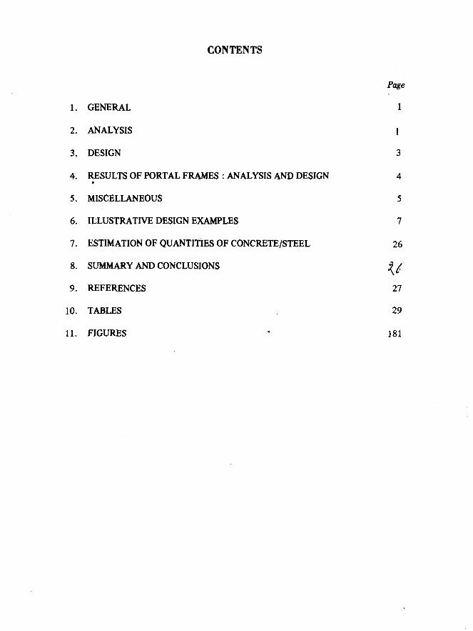
CONTENTS
1.
2.
3.
4.
5.
6.
7.
8.
9.
10.
11.
GENERAL
ANALYSIS
DESIGN
RESULTS OF PORTAL FRAMES : ANALYSIS AND DESIGN e
MISCELLANEOUS
ILLUSTRATIVE DESIGN EXAMPLES
ESTIMATION OF QUANTITiES OF CONCRETE/STEEL
SUMMARY AND CONCLUSIONS
REFERENCES
TABLES
FIGURES .
1
I
3
26
27
29
181
SP 43 (S & T): 1987
1. GENERAL
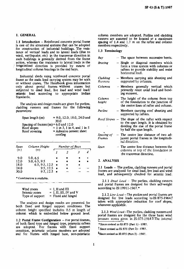
1.1 Introduction - Reinforced concrete portal frame is one of the structural systems that can be adopted for construction of industrial buildings. The resis- tance of vertical loads and to lateral loads (due to wind, earthquake, etc) in the transverse direction in such buildings is generally derived from the frame action, whereas the resistance to lateral loads in the longitudinal direction is provided by means of longitudinal column bracings in the end bays.
Industrial sheds using reinforced concrete portal frame as the main load carrying system may be with or without cranes. The Handbook gives information only about portal frames without cranes but subjected to dead load, live load and wind load/ seismic load according to appropriate Indian Standards.
The analysis and design results are given for purlins, cladding runners and frames for the following parametres:
Span length (m) = 9.0,12.0,18.0,24.0and 30.0
Spacing of frames (m) = 6.0 and 12.0 Roof slopes =1in3,1in4,and1in5 Roof covering = Asbestos cement sheet
roofmg
Span Column Height Number of Bays (m) W f I
1 2 3 4
9.0 5.0, 6.5 * * * * 12.0 5.0,6.5,9.5 * * * * 18.0 6.5,9.5,12.5 * * * 24.0 9.5,12.5 * * - - 30.0 9.5,12.5 * - - -
* Combination is available.
Wind zones = I, II and III Seismic zones = I, II, III, IV and V Type of support = Fixed and hinged
The analysis and design results are presented for both fared and hinged support conditions. The column height specified includes 0.5 m length of column which is embedded below ground level.
1.2 Portal Frame Confguration - For portal frames, of both fixed type and hinged type, prismatic rafters are adopted. For frames with fixed support condition, prismatic cohunn members axe adopted and for frames with hinged base, non-prismatic
column members are adopted. Purlins and cladding runners are assumed to be located at a maximum spacing of 1.4 and 1.7 m on the rafter and column members respectively.
1.3 Terminology
Bay -
Bracing -
Cladding - Runners
Columns -
Column - height
Purlins -
Roof Slopes -
Spa c*ng of - Frames
-Span -
2. ANALYSIS
The space between successive bents.
Single or diagonal members which form a truss system with columns or rafters to provide stability and resist horizontal load.
Members carrying side sheeting and supported by columns.
Members generally vertical which primarily resist axial load and bend- ing moment.
The height of the column from top of the foundation to the junction of the centre lines of rafter and column.
Members carrying roof sheeting and supported by rafters.
The slope of the rafter with respect to the span length. It is obtained by dividing the rise of the portal frame by half the span length.
The centre line distance of two ad- jacent portal frames in the longitudi- nal direction.
The centre line distance between the columns at top of the foundation in the transverse direction.
2.1 Loads - The purlins, cladding runners and portal frames are analyzed for dead load, live load and wind load, and subsequently checked for seismic load.
2.1.1 Dead Load - The purlins, cladding runners and portal frames are designed for their self-weight according to IS:19911-1967.*
2.1.2 Live Load -The purlinsand portal frames are designed for live loads according toIS:875-1964.f taken with appropriate reduction for roof slopes, whenever applicable.
2.1.3 Wind Load -The purlins, cladding runners and portal frames are designed for the three basic wind pressure zones given in ,13:875-1964s The internal
*Since revised as IS:875 (Part 1) - 1987.
t Since revised as IS:875 (Part 2) - 1987.
%ince revised as IS:875 (Part 3) - 1987.
1

SP43(S&T):1987
pressure/suction specified in IS:8751964,* for buildings with normal permeability (+ 0.2~) has been considered. Under each basic wind pressure, the following t.hree different wind load conditions (see Drg. 142) have been analyzed:
a) Wind perpendicular to the ridge with internal suction (WL 1)
b) Wind perpendicular to the ridge with internal pressure ( WL 2)
C) Wind parallel to the ridge with internal pressure (WL 3)
The basic wind pressure is reduced by 25 ‘percent for the design of all members if the height of the building is less than 10.0 m and for columns alone if the height of the building is more than 10.0 m but less than 30.0 m.
In the case of multi-bay portal frames, drag force due to wind on interior slopes has also been considered according to IS:8751964.*
Cladding and cladding fasteners shall be designed for increased wind pressure due to local effects according to IS:8751964.*
2.1.4 Seismic Load - Seismic load is generally not of significance for low rise buildings such as those considered in the Handbook. But a few cases of frames with the shortest spans and the shortest column height, and also of frames with the largest spans and the largest column height have been checked for seismic load effects. The seismic load characteristics and intensities in such cases are assumed as specified for different earthquake zones in 13:1893-1984.
Snow load has not been considered for the typification.
2.2 Analysis of Purlins - The maximum spacing of purlins is assumed to be 1.40 m centre-to-centre supporting asbestos cement sheets. Galvanized iron sheeting may be used in place oi 4C sheeting without any modifications. However, in case of GI sheeting, if a larger spacing than 1.40 m is to be adopted (as per recommendation of the manufacturers), the purlins will have to be suitably redesigned. The portal design will remain unaltered.
Purhns are analyzed as simply supported beams subjected to biaxial moment due to dead load, live load and wind load/seismic load as described in 2.1.
First the bending moments due to the dead load (DL), live load (LL) and the wind loads (WL 1, WL 2, WL 3) are computed. For checking the permissible stresses at various service load stages of 12 m prestressed concrete purlin, the load combinations as shown below are considered:
a) DLtLL b) DLtLLtWLl c) DLtLL+WL2 d) DLtLLtWL3
*Since revised as I$875 (Part 3) - 1987.
2
For the purposes of design of both the reinforced concrete (RC) and prestressed concrete (PSC) purlins according to the limit state of collapse, the design forces in the appropriate planes are arrived at in accordance with IS:456-1978 and IS:1343-1980 for load combinations shown below:
a) 1.5DL t1.5LL b) 1.5DL+1.5C,,WLl c) 1.5DL t1.5GWL2 d) l.SDLtl.Sc,WL3 e) 0.9DL t1.5C,,WL 1 f) 0.9DL t1.5c,WL2 g) 0.9DL t1.5c,WL3 h) 1.2DL t1.2LL + 1.2C, WL 1 j) 1.2DLt1.2LLt1.2C,,WL2 k) 1.2DL t1.2LL t 1.2C, WL 3
Where C, = 0.75 for members of building whose heights are less than or equal to 10.0 m and for columns of buildings whose height is less than 30.0 m and C,, = 1 .O for all other cases.
2.3 Analysis of Cladding Runners - Cladding runners of span 6.0 m and 12.0 m span are analyzed as simply supported beams for the loads described in 2.1. The load combinations considered for evaluating the design bending moments at the service load stage and .the limit state of collapse are as given in 2.2.
2.4 Analysis of Portal Frames - All the portal frames are analyzed according to the principles of elastic theory for dead load, live load and wind load as described in ‘2.1. For simplifying the analysis, the loads are assumed to act at four intermediate points on the rafter andat one intermediate point on the column.
It is assumed that the frames are supported on an isolated footing. In the case of isolated footing, the idealized support condition for the column can be fixed end condition or hinged end condition depending on the soil strata. If the isolated footing is resting on hard rock, it can be assumed as a fiied base because the rock will not deform much to allow the rotation of the foundation, and if it is resting on normal soil, it can be assumed as hinged because due to the compressibility of the soil, the foundation can undergo a rotation relieving off the moment. In the case of the columns supported by a pile foundation, the base of the column should be assumed as fixed. Analysis has been carried put for both cases of support conditions, that is, fured and hinged.
The portal frames have been analyzed using a plane frame computer programme which is based on stiffness method of analysis. Three degrees of freedom are assumed at each node. In this method, the structure coordinates are specified at all the nodal points including the supports. The number of forces at each node is equal to the possible degrees of freedom per node that are inputted. Then, the stiffness matrix of the structure is assembled and the boundary conditions are incorporated. The resulting simultaneous equations are solved for displacements, using which the member end actions are finally obtained.

3. DESIGN
3.1 Materials
3.1 .I Concrete - Since the designs presented in the Handbook could be used either for a cast in-situ construction or for a precast construction, M25 concrete is used for the design of all portal frames, and of 6.0 m span RC purlins and cladding runners. For the illustrative design of bracings in concrete, M2S concrete is used. The 12.0 m span PSC purlins and cladding runners are designed using M40 concrete which is the minimum grade prescribed for pretensioned prestressed concrete work. For the illustrative design of foundation, Ml5 concrete is used.
3.1.2 Steel - High yield strength deformed bars conforming to 13:1786-1985 are used as reinforce- ment in all RC members except in case of ties for purlins and cladding runners for which mild steel conforming to IS:432 (Part 1)1982 is used. The pretensioned prestressed concrete purlins and cladding runners of 12.0 m span are assumed to be prestressed using 3 ply, 3 mm diameter uncoated stress-relieved strands conforming to IS: 6006-l 983.
3.2 Basic Criteria for Design
3.2.1 Limit States of Collapse and Serviceability - Design of reinforced concrete or prestressed concrete structural members is carried out to satisfy the criteria laid down in 18:456-1978 and IS:1343-1980 for safety against limit state of collapse, and limit states of cracking and deflection at working load stage, whenever available. In addition to the specific guidelines available in the respective Indian Standards for ensuring the required safety against limit state of collapse, both for reinforced concrete members and prestressed concrete members, the safety against cracking is assured in prestressed concrete members through the provision of limiting stresses under working load stage. 133456-1978 has specific recommendations also for limiting deflections of simple flexural members like purlins and cladding runners.
No specific recommendations exist at present in IS:456-1978 for calculation of crack width or on lateral deflection of structural systems such as portal frames. Crack widths have been investigated based on the formulae of AC1 318-1983 and a value of height/325 has been adopted as the limihg deflection for the lateral deflection of the portal frames when the deflections are calculated using the values of Young’s modulus and effective moments of inertia as recommended in IS:456-1978.
3.2.2 Choice of Preliminary Cross-Sectional Shape and Dimensions - In reinforced and prestressed concrete structures, the self-weight of the structural members contributes quite significantly to the total vertical load coming on to the structural members. Furthermore, in the design of statically indeter- minate structures like portal frames, the relative
SP43(S&T):1987
dimensions of different structural components influence the analysis. Hence, considerable thought had to be given for the choice of cross-sectional shapes and dimensions.
The purlins and cladding runners are supported and analyzed as simply supported members of 6 or 12 m span. The cross-section shape chosen is either an angle section or a channel section because these are the most suitable ones for a member subjected to biaxial bending permitting at the same time easy fixing on to the lugs.
For the main portal frames, a solid rectangular section has been chosen mainly from the considera- tions of ease of construction and partly from the considerations of stiffness against lateral loads. Particularly in the case of long span and relatively high portal frames, it has been observed that the imposed limit of height/325 on the lateral deflection governs the design rather than the strength. In case a user decides to adopt a section which is governed by only strength and not deflection, then the sections can be redesigned making use of the analysis tables given in the Handbook.
3.2.3 Load Combination Governing ihe Design - From amongst the large number of load combinations listed in 2.2, the governing load is that which gives the bending moment or that combination of bending moment and axial force which requires the maximum percentage of steel at the section under consideration. Thus, it is possible that designs of different sections are governed by different combinations of the possible loads.
3.i Design of the Purliis Cladding Runners - The purlins and the cladding runners can be of reinforced concrete, prestressed concrete or steel sections. In the Handbook, details of 6.0 m span RC purlins and cladding runners, and 12.0 m span prestressed concrete purlins and cladding runners are given. However, hot rolled angle or channel sections or cold formed Z-sections can also be used as purlins.
3.3.1 Design of the 6.0 m Span RC Purlins and Cladding Runners - 6.0 m span RC purlins and clad- ding runners are designed by the limit state method according to 13:456-1978 for the governing bending moments and shear forces obtained from the analysis. It is found that the design is not very much influenced by the variation of the roof slope and wind load/seismic load. Hence, one common design is given for all the load cases described in 2.2. Effect of torsion is neglected as it is not significant.
3.3.2 Design of the 12.0 m Span. Prestcessed Concrete ,Furlins and Cladding Runners - The pre- stressed concrete purlins and cladding runners are designed for the bending moments and shear forces described in 2.2 according to IS:1343-1980. Since it is found that the design of the purlins and cladding runners is not very much influenced by the variation in roof slopes and the wind load/seismic load, only one common design is given. This is applicable for
1 -
3

SP 43 (S & T):1987
frames with all slopes considered and for all wind zones/seismic zones.
3.4 Design of the Portal Frames
3.4.1 Strength Design - The critical sections of the principal rafter and the column of the portal frames are designed for all the load combinations given in 2.2. The effective length for strong axis buckling under axial compression of the columns has been considered as 1.5 times the actual columns height for fixed type of support and 2.25 times the actual length for hinged type of support according to the provisionsof IS:456-1978. Theeffective length for weak axis buckling of columns under axial compression has been considered as 0.75 times the height for fwed and hinged type of supports follow- ing the provisions of IS:800-1962. The columns are designed for bending moment along minor axis also, wherever applicable.
It is found that the design of the critical cross- sections of a portal frame is not very much influenced by the variation hi slopes and wind/seismic loads. Hence, common designs are worked out which are applicable for all slopes and wind/seismic forces. With the critical cross-sectional details being common for all slopes, the influence of the slope has been incorporated while fming the lengths of the rafters, location at which bars could be curtailed and other points related to reinforcement detailing. Normal clear cover according to IS:456-1978 is assumed in the design. In a particular case, if additional cover has to be provided due to aggressive environment, etc, then the column dimensions have to be increased to the extent of increase in the cover. In the design of the rafter, the effect of axial force is neglected as it is not significant.
3.4.2 Deflection - As already mentioned, it is ensured that the lateral deflection at the top of the columns is less than l/325 of height of the columns under the worst combination of all the vertical and lateral loads. It is significant to note here that a considerable portion of the lateral deflection at the top of the column is due to the action of vertical loads themselves.
3.4.3 Crack Width - The maximum widths of the cracks in the portal frames are checked according to ACI-318-1983 and they are found to be within the permissible values.
3.4.4 Special Considerations for Frames in Seismic Zones - As mentioned in 2.1.4, some of the frames with largest span and largest column height, as well as shortest spanand shortest column height are analyzed for seismic forces. It is found that the seismic forces dq not govern the strength design. However, the joints in the frames to be constructed in areas where seismic coefficient is 0.05 or more are to be so detailed that enough ductility is ensured according to 18:4326-1976. These special joint details should be incorporated at the joints of the frames to be constructed in areas where seismic coefficient is 0.05
or more even though the seismic load does not govern the design.
4. RESULTS OF PORTAL FRAMES: ANALYSIS AND DESIGN
4.0 The results of the extensive analysis and design work carried out for the large number of portal frame configurations as described in the earlier clauses are presented in the form of detailed design drawings and tables. ,
Whereas the detailed design drawings prepared can be straight away adopted for fabrication and erection, they are naturally strictly valid only for the definite set of assumptions like the material properties, section dimensions and other relevant data chosen as the basis for design. On the other hand, information given in the analysis tables about bending moments, shear forces and axial forces at critical sections will at times be useful to such of those designers who may, for valid reasons, like to adopt different materials, say M20 grade of concrete, for example, or deviate marginally from the section dimensions chosen. The values obtained for design bending moments, shear forces and axial forces in the present analysis should be applicable quite closely for any frame of the same overall dimensions as long as the areas and moments of inertia of the alternative sections chosen do not deviate too much from those adopted in the designs presented in the Handbook. In a large number of cases, such values will be of immense use at least in working out preliminary designs. Hence, information is presented in the form of design tables ‘svhich give the design bending moment, shear force and axial forces not only at all critical sections of the portal frames but also at the foundation level of each frame.
4.1 De&n Tables
4.1.1 Portal Frames - Tables 1 to 140 give complete information about bending moments, shear forces and axial forces at all the critical sections for each of the 140 portal frames typified in the Handbook. All the values given for the critical sections of the portal frames are for the ultimate load stage. It may, however, be noted that the combi- nation of loadings governing the design of different critical sections may be different and hence the design bending moments, shear forces and axial forces given in each of the tables for each critical section may be from a different set of load combinations. This is appropriately accounted for whi?e considering the governing load combinations. It needs to be emphasized here that the bending moments, shear forces and axial forces given in Tables 1 to 140 give the values from the basic analysis of the portal frames. Slenderness effects are not included in the values given in these tables. Hence, any designer who wishes to make use of the values given in these tables should be careful to take into account the additional slenderness effects, wherever applicable.
SP43(S&T):1987
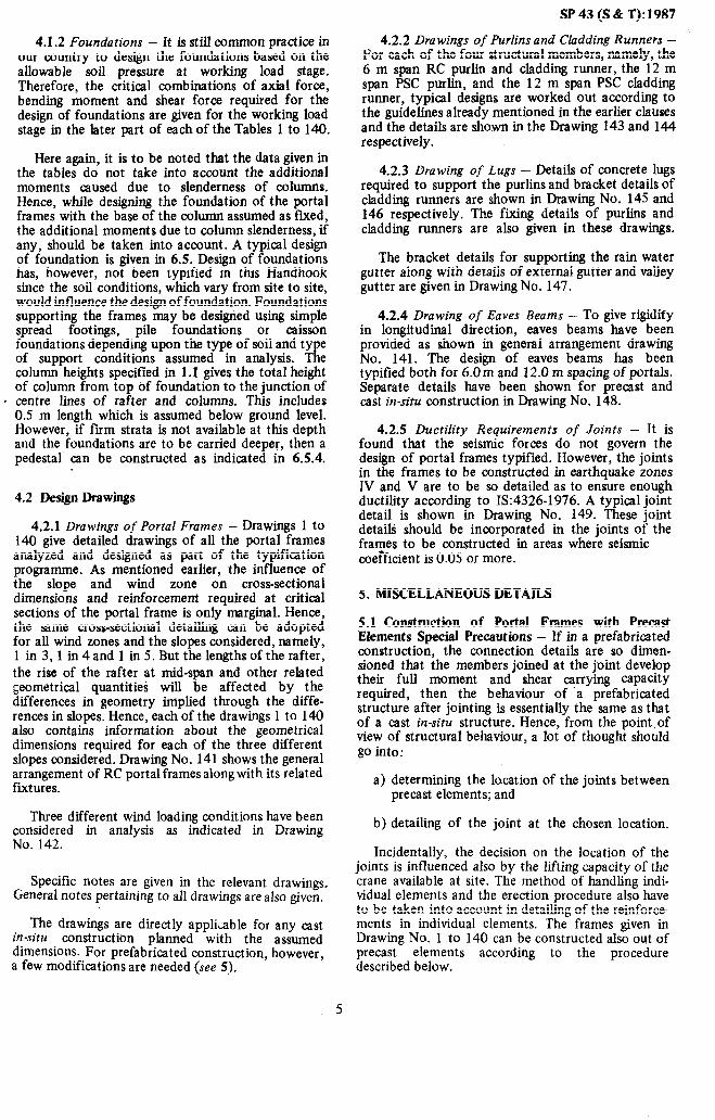
4.1.2 Foundations - It is still common practice in our country to design the foundations based on the allowable soil pressure at working load stage. Therefore, the critical combinations of axial force, bending moment and shear force required for the design of foundations are given for the working load stage in the later part of each of the Tables 1 to 140.
Here again, it is to be noted that the data given in the tables do not take into account the additional moments caused due to slenderness of columns. Hence, while designing the foundation of the portal frames with the base of the column assumed as fixed, the additional moments due to column slenderness, if any, should be taken into account. A typical design of foundation is given in 6.5. Design of foundations has, however, not been typified in this Handhook since the soil conditions, which vary from site to site, would influence the design of foundation. Foundations supporting the frames may be designed using simple spread footings, pile foundations or caisson foundations depending upon the type of soil and type of support conditions assumed in analysis. The column heights specified in 1.1 gives the total height of column from top of foundation to the junction of
. centre lines of rafter and columns. This includes 0.5 m length which is assumed below ground level. However, if firm strata is not available at this depth and the foundations are to be carried deeper, then a pedestal can be constructed as indicated in 6.5.4.
4.2 Design Drawings
4.2.1 Drawings of Portal Frames - Drawings 1 to 140 give detailed drawings of all the portal frames analyzed and designed as part of the typification programme. As mentioned earlier, the influence of the slope and wind zone on cross-sectional dimensions and reinforcement required at critical sections of the portal frame is only marginal. Hence, the same cross-sectional detailing can be adopted for all wind zones and the slopes considered, namely, 1 in 3,1 in 4 and 1 in 5. But the lengths of the rafter, the rise of the rafter at mid-span and other related geometrical quantities will be affected by the differences in geometry implied through the diffe- rences in slopes. Hence, each of the drawings 1 to 140 also contains information about the geometrical dimensions required for each of the three different slopes considered. Drawing No. 141 shows the general arrangement of RC portal frames along with its related fixtures.
Three different wind loading conditions have been considered in analysis as indicated in Drawing No. 142.
Specific notes are given in the relevant drawings. General notes pertaining to all drawings are also given.
The drawings are directly appliable for any cast in-situ construction planned with the assumed dimensions. For prefabricated construction, however, a few modifications are needed (see 5).
4.2.2 Drawings of Purlins and Cladding Runners - For each of the four structural members, namely, the 6 m span RC purlin and cladding runner, the 12 m span PSC purlin, and the 12 m span PSC cladding runner, typical designs are worked out according to the guidelines already mentioned in the earlier clauses and the details are shown in the Drawing 143 and 144 respectively.
4.2.3 Drawing of Lugs - Details of concrete lugs required to support the purlins and bracket details of cladding runners are shown in Drawing No. 145 and 146 respectively. The fixing details of purlins and cladding runners are also given in these drawings.
The bracket details for supporting the rain water gutter along with details of external gutter and valley gutter are given in Drawing No. 147.
4.2.4 Drawing of Eaves Beams - To give rigidity in longitudinal direction, eaves beams have been provided as shown in general arrangement drawing No. 141. The design of eaves beams has been typified both for 6.0 m and 12.0 m spacing of portals. Separate details have been shown for precast and cast in-situ construction in Drawing No. 148.
4.2.5 Ductility Requirements of Joints - It is found that the seismic forces do not govern the design of portal frames typified. However, the joints in the frames to be constructed in earthquake zones IV and V are to be so detailed as to ensure enough ductility according to 18:4326-1976. A typical joint detail is shown in Drawing No. 149. These joint details should be incorporated in the joints of the frames to be constructed in areas where seismic coefficient is 0.05 or more.
5. MISCELLANEOUS DETAILS
5.1 Construction of Portal Frames with Precast Elements Special Precautions - If in a prefabricated construction, the connection details are so dimen- sioned that the members joined at the joint develop their full moment and shear carrying capacity required, then the behaviour of ‘a prefabricated structure after jointing is essentially the same as that of a cast in-situ structure. Hence, from the point\of view of structural behaviour, a lot of thought should go into:
a) determining the location of the joints between precast elements; and
b) detailing of the joint at the chosen location.
Incidentally, the decision on the location of the joints is influenced also by the lifting capacity of the crane available at site. The method of handling indi- vidual elements and the erection procedure also have to be taken into account in detailing of the reinforce- ments in individual elements. The frames given in Drawing No. 1 to 140 can be constructed also out of precast elements according to the procedure described below.
5

SP43(S&T):1987
‘5.2 Suggested Sckme of Cast& and Erection - The frames are cast as segments as shown in Drawing No. 150. The segments are cast flat on the ground. They are lifted in horizontal position using the points for transportation shown in Drawing No. 150. Schematic details of different types of futures used for handling precast members are given in Drawing No. 15 1. Then the columns are tilted, erected, aligned and laterally braced. Temporary bracings and other such precautions should be taken, as found necessary during erection. The columns are erected using the holes provided for erection as shown in Drawing No. 150. The distances marked as a and b in Drawing No. 150 are given in Table 141. The typical details of the connection between precast columns and foundations in the case of fixed bases and hinged bases are shown in Drawing No. 152 for the typical design worked out in 6.5.2 and 6.5.3.2. Of course, any other suitable details can also be adopted depending on the site conditions. Next, the rafter is erected in the vertical position using the holes provided for erection. The tie member shall be -suitably tightened before lifting so that there are no erection stresses induced in the rafter. After aligning, the joints are made. It is always desirable to provide the joints in the rafter at the points of contra- flexure. But these points will get shifted depending on the loading condition. Hence, it is not possible to fix a permanent point of contraflexure. So there can be some bending moments in the joints. Hence, it is advisable to provide a moment resisting connection. Two typical joint details are shown in Drawing No. 153. The salient dimensions indicated in Drawing No. 153 are given in Table 142. As in the case of the connection between columns and foundations, any other suitable connection details can also be adopted depending on the field conditions.
The basic aim during erection should be to commence and complete the erection of an end bay or group of bays in which bracing has been incorporated before proceeding with the erection of the remainder of the structure. Components of the end bay or bays will require support until the bracing has been completed. Purlins and cladding runners should not be relied upon to provide stability.
When permanent bracings are included elsewhere in the building than in the end bay, erection should commence at the bay or group of bays where they have been incorporated, unless temporary bracing is used. Where nature of design precludes erection in the foregoing manner, proper steps should be taken to provide alternative support.
Precast reinforced concrete, and prestressed concrete purlins and cladding runners are handled at the support points during erection and these are shown in the respective drawings. They should be lifted in the same position in which they are to be finally placed at site.
5.3 Suggested Locations of Joints - Although one should try to have a joint with sufficient moment resisting capacity, it is always an advantage to have
the joints at the point of contraflexure or at least in a zone with very small bending moments. Table 141 gives the information about the recommended points at which joints and lifting hooks can be provided in the rafters and in the columns for all the 140 frames typified in this Handbook. The main reinforcement in the precast column and rafter members need not undergo any change from what has been given in Drawing No. 1 to 140 as they are found to be adequate to withstand possible handling stresses also.
5.4 Bracing - Even though bracing may appear to be a secondary matter, it is highly important and deserves careful attention. Probably more failures, or at least unsatisfactory performances, have resulted from inadequate bracing than from deficiencies in main framing. There can be several alternatives by which loads can be carried to the ground and in a number of bays redundant diagonals may be used. This makes the design of bracing in even simple structures highly indeterminate.
In order to ensure stability in the longitudinal direction, to take the wind forces acting on gable end and the forces due to wind drag on roof, bracings have to be provided at the rafter level and in the vertical plane between columns. Normally, these bracings are provided in the end bays - one at each end of building. If the length of the building is large, bracings are provided in some of the intermediate bays also. A typical arrangement of bracings is shown in Drawing No. 154.
The diagonal bracing members can be either in concrete or in steel. Section dimensions required for the bracing members either in concrete or in steel depend on the total horizontal force coming on the building in the longitudinal direction. This, in turn, depends on the area of the gable end of the building, surface area of the roof and the wind zone in which the building is situated. A design of such a bracing in concrete and in steel for one typical case is presented in 6.6. Details of the bracings designed in the illustrative example are shown in Drawing No. 155. The bracings needed in any given case can be designed on similar lines. Typification for bracing has not been attempted since lot of variations are possible due to different design parameters like length of building, span, spacing, height, wind zone, etc.
5.5 Expansion Joints - Expansion joints have to be provided after taking into consideration various factors, such as temperature, exposure to weather, the time and season of laying of concrete. For the purpose of general guidance, however, it is recommended that structures exceeding 45 m in length shall be divided by one or more expansion joints.
The structures adjacent to the joint should preferably be supported on separate columns but not necessary on separate foundations. The wind bracing is discontinuous across expansion joint and hence the bracing systems should be structurally independent in each segment of the structure separated by expansion joints.
6

Total dead load
SP 43 (S & T): 1987
=0.289 + 0.625 + 0.060 =0.974 kN/m
5.6 The use of the data represented in Tables 1 to 140 is illustrated by means of an example worked out in full detail in Section 6. The design example illustrates completely the procedure to be followed in the design of purlins, cladding runners, the portal frame proper and also in the design of a suitable foundation and bracing system.
For laying of asbestos cement sheets, recommen- dations of IS:3007(Part l&1964 shall be followed.
6. ILLUSTRATIVE DESIGN EXAMPLE
6.1 Basic Data
Plan area of the factory building = 18.0 m x 30.0 m
Span of the portal frame = 18.0 m Number of bay = 1 Height of the column r
above the foundation = 6.5 m Slope of the roof = 1 in 3 (18.435’) Type of support at the
base of the column = Fixed Spacing of the frames = 6.0 m Location of building = Madras Basic wind pressure = 2 kN/m’ Type of sheeting. = AC sheeting
Assume building of normal permeability.
6.2 Design of the Cladding Runner - It is assumed that AC sheet cladding is provided. The sheets are supported on RC cladding runners spaced at 1.70 m centre-to-centre. The width of the frame is 400 mm.
6.2.1 Span - Effective span of the cladding runner
= 6 000-10-10-95-95
= 5 790 mm.
6.2.2 Loads
6.2.2.1 Dead load
Weight of roof material = 17 kg/m2 (including extra weight due to overlaps and fasteners)
The dead load acts in the vertical plane.
Assume Lshaped cladding runner of size =250 mm x 300 mm
x50mm Weight of the sheet Self-weight of the
cladding runner
Miscellaneous load
=0.17 x 1.7 = 0.289 kN/m
=(0.2x 0.05 + 0.30 x 0.05) x 25
=0.625 kN/m =0.035 x 1.7 = 0.060 kN/m
6.2.2.2 Wind load - The wind load acts in the horizontal plane. When the wind blows perpendicular to the ridge, the wind load on the cladding runner
=0.75 x0.7 x2 xl.7 = 1.785kN/m
6.2.3 Design Forces -Effect of torsion is neglected as it is insignificant and only the effect of bending and shear is considered.
6.2.3.1 Design forces due to dead load - T&&n moment for limit state design or factored moment*
= 1.5 x 0.974 x 5.792
8
= 6.12 kN*m
Shear force due to 1.5 x 0.974 x 5.79 factored loads V, =
2
=4.23 kN
6.2.3.2 Design forces blowing normal to ridge),
Factored moment =
due to wind load (wind,
1.5 x 1.785 ~5.79~
8
= 11.22 kN*m
Factored shear force 1.5 x 1.785 x 5.79
= 2
=7.75 kN
6.2.4 Design -Let the area of steel for the cladding runner is as shown. Then the moment of resistance under various load combinations is checked.
1 300 1
1 1
*The term ‘factored moment’ means the moment due to characteristic loads multiplied by the appropriate value of partial safety factor.
7

SP 43 (S & T): 1987
6.2.4.1 Dead load
.
DEAD LOAD ro-0035 I -t+
r0.45 fck +t
J I I
at2
Factored moment = 6.12 kN.m
Assume depth of neutral axis, X, 125 mm
Therefore, strain, fst1 = 0
0.003 5 and f st2 = - x 200
25
=0.028
Nominal shear stress, 7v = 4.23 x IO3
... 50 x225 .
= 0.38 N/mm*
Percentage of steel neglecting the steel in the horizontal leg,
’ 201 x 100 Pt = = 1.78 percent
50 x 225
From stress-strain curve for F, 415 steel,
Stress, f,t 1 =o
f St2 ~360 N/mm*
Using M 25 concrete, characteristic compressive strength,
f ck ~2.5 N/mm2
Compressive force in concrete,
C =u.36 fckXu b =0.36 x 25 x 25 x300
=67 500 N
From Table 13 of 18:456-1978, design shear stress,
7~ = 0.78 N/mm* > 0.38 N/mm’. Hence safe,
Hence, minimu; web steel according to 25.5.1.6 of 18:456-1978 may be provided.
6.2.4.2 Dead and wind load - The section is designed for the simultaneous action of the dead and wind load. Two cases are considered.
Case 1 : Cladding runner on the leeward side when the wind blows perpendicular to the ridge with internal pressure :
Factored moment due to dead load, MUD = 6.12 kN.m
Tensile force in steel, T =201 x 360
=79360N>C
Limiting moment of resistance, M, , Lim =67 500 x
(225 - 0.42 x 25) x 1O-6
~14.48 > 6.12 kN.m
Factored moment due to wind load, M, w = 11.22 kN.m
Resultant factored moment, M,, = ~6.122t11.222
= 12.78 kN.m
Inclination of the neutral axis with the verticle.
The section is designed for factored shear due to dead load neglecting the horizontal leg.
0 = tan-l. (6.12) I ) 11.22
Factored shear force, Vu = 4.23 kN = 28.61’
8

SP 43 (S & T): 1987
Assume the depth of neutral axis, X, = 150 mm
Solving graphically,
d SC = 150-35 =115mm
d stl = 254-150 =104mm
d st2 = 349 - 150 =I99 mm
From strain diagram,
0.0035x115 Strain, esc =
150
0.003 5 x 104
= 0.002 7
tst1 = = 0.0024 150
0.003 5 x 199 est2 = - = 0.004 6
150
From stress-strain curve for steel:
Stress, fsc = 350 N/mm2
f ’ St1 = 342 N/mm2
fst2 = 360 N/mm2
Compressive force in concrete =0.45 x 25 (; x 58 x 24
+ 58 x 40.2) + 0.45 x 25
x ; x 58 x 85.8
=34060+37 323
=71 383 N
Resultant compressive force, C =350 x 113 f 71 383
=39 550 + 71 383
=110933N
Resultant tensile force, T =342 x 113 + 360 x 201
=38646+72360
=111006 = c
Hence, the assumed neutral axis is alright.
Taking the moment of all the compressive forces about the top fibre, distance of centre of compression from top fibre,
F = 34 060 x 64.2
-t 37 323 x (; x85.8 + 64.2) 2
39 550 x 35 t
* 110 933
= 54.76 mm
Moment of the tensile forces about the centre of compression,
MU, lim = 38 646 x‘(254 - 54.76) + 72 363
(349 - 54.76) x lo”
= 29.0 kh/rn > 12.78 kN/m
Hence, the assumed section is alright.
Case 2 : Cladding runner on the windward side, when the wind blows perpendicular to the ridge with internal suction:
Factored moment due to dead load, MU o = 6.12 kN/m
Factored moment due to wind load, M,,w = 11.22 kN/m
Resultant factored moment, Mu = d6.122+11.222
= 12.78 kN.m
9

SP43(S&T):1987
Inclination of the neutral axis with the vertical
= 28.61’
Assume the depth of the neutral axis to be 90 mm
Solving graphically, d,, = 90 - 33.9 = 56.1 mm
d stl =129.7 - 90 = 39.7 mm
d st2 =241 - 90 = 151
/
From the strain diagram,
Strain, e,, = - 0.003 5 x 90
56.1 = 0.002 2
es*r = 0.003 - 5 x 90
39.7 = 0.0015
estz = o.003 90 x 151 =O.O058
From the stress-strain curve for steel,
Stress, f,, = 335 N/mm2
f stl = 295 N/mm2
f st2 = 361 N/mm2
Force in the steel,
F SC = 113 x335 =37 855 N
Fstz= 113x361 =40793N
Compressive force in concrete,
~0.45 x25 x?4 x96 x38.6 + (0.45 t 0.28) x ‘A x 25 x ?4 x(162+96)x 28 t M x0.28 x 25 (23.4 x 56 + 102 x 23.4) = 20 844 + 32 960 + 12 940 =66744N
Resultant compressive force, C
=37855+66744=104599N
Resultant tensile force, 7’
= 59 295 + 40 793 = 100088N-c c.
Hence, the assumed neutral axis is ahight.
Taking moment of all the compressive forces about the top .fibre, distance of centre of compression from top fibre, ~
_‘f= 208~x38.6+32960 (11*25+2x 7, x28
2 11.25 + 7
12 940x 41 x23.4 + 37 855 x 33.9 t
104 599
= 29.8 mm
Moment of the tensile forces about the centre of compression,
M,, him = _[59 295 (129.7 - 29.8) + 40 793
(241 - 29.8)] x lo”
= 14.53 kN/m > 12.78 kN/m
Hence, the assumed section is alright for the combination of the dead load and wind load moments.
The section is designed for the maximum factored shear due to wind load neglecting the vertical leg.
Factored shear force, Vu = 7.75 kN
IO

Nominal shear stress, 7, = z-5_‘! ‘_9” 50 X275
= 0.56 N/mm2
Percentage of steel nelgecting the steel in the artical leg,
113X IO0 =082 Pt = 50X275 .
Design shear stress of the concrete, from Table 13 of IS:45&1978,
rc = 0.59 N/mm2 > 0.56N/mm2
Hence, nominal web reinforcement according to 25.5.1.6 of 18:456-1978 is adequate.
Assuming 6 mm diameter mild steel as single legged web reinforcement, spacing of the web steel,
s,, = Aw x’fy 28x250 - z,z- = 350 mm
0.4 b 0.4 x 50
Maximum permissible spacing according to 25.5.1.5 of IS:456-1978
= 0.75 x 225 = 169 mm
Therefore, provide 6 mm single legged web steel at 160 mm centre-to-centre in both the legs.
6.3 Design of the Purlins - It is assumed that the shed is covered with asbestos sheets supported by purlins placed at 1.40 m centre-to-centre.
6.3.1 span - Effective span of the purlin
= 6000-10-10-95-95 = 5 790 mm
6.3.2 Loads
6.3.2.1 Dead load
An L-shaped purlin of dimensions
= 200 x 250 x 50 mm is adopted.
Weight of the sheet = 0.17 x 1.4 = 0.238 kN/m
Self-weight of the purlin = (0.20 + 0.20) x 0.05 x 25 = 0.50 kN/m
Miscellaneous loads = 0.035 x 1.4 = 0.049 kN/m
Total dead load = 0.238 t 0.50 + 0.049 = 0.787 kN/m “- 0.80 kN/m
6.3.2.2 Live load - Live load according to 18:875-1964,
= 0.75 - 0.02 (18.4 - 10) = 0.581 kN/m’
SP 43 (S & T):1987
Live load on the purlin = 1.4 x0.581 = 0.8lkN/m.
6.3.2.3 Wind load - Since the height of the entire structure is less than 10 m, the basic wind pressure = 0.75 p
Wind blowing parallel to the ridge gives the maximum wind load on the purlin according to 18:875-1964.
Internal pressure =0.8X0.75x2 =
Wind load on the purlin
1.2 kN/m2
= 1.2 x 1.4 = 1.68 kN/m
6.3.3 Design Forces
6.3.3.1 Design for’.es due to the dead load
Bending moment due to the dead load in the vertical plane,
M,, = 0.8 x 5.79’
8
= 3.35 kN.m
.: Shear force in the vertical plane,
0.8 x 5.79 VI) =
2
s = 2.32 kN
Component of the moment in the normal plane,
M ,,” = 3.35 X cos 18.4
= 3.18 kN.m
Component of the bending moment in, the tangential plane,
MDt = 3.35 x sin 18.4
= 1.06 kN.m
Shear force in the normal leg, I/‘n” = 2.32 X Cos 18.4
= 2.20 kN
Shear force in the tangential leg,
V Dt = 2.32 x sin 18.4 = 0.73 kN
6.3.3.2 Design forces due to the live load
Bending moment due to the live load, M = 0.81 x 5.792
L - = 3.39 kN.m 8
11

SP 43 (S & T): 1987
Shear force in the vertical plane = 0.81 x 5.79
2 Case 2: 0.9 DL t 1.5 WL
= 2.35 kN
Component of the live load bending moment in the normal plane,
ML,, = 3.39 x cos 18.4 = 3.22 kN.m
Component of the live load bending moment in the tangential plane,
ML, = 3.39 x sin 18.4 = 1.07 kN.m
Shear force in the normal plane,
VLn = 2.35 x cos 18.4’ = 2.23 kN/m
Shear force in the tangential plane,
VLt = 2.35 x sin 18.4” = 0.74 kN
6.3.3.3 Design forces due to the wind load
Bending moment due to the wind load which is in the normal plane,
M = 1.68 x 5.792 W
8 = 7.04 kN.m
Shear force in the normal plane,
1.68 x 5.79 = -- = 4.86 kN 2
6.3.3.4 Resultant design forces
CaseI:1.5DL+l.SLL
Factored moment in the.normal plane,
M un, = 1.5 x 3.18 + 1.5 X3.22
= 9.60 kN.m
Factored moment in the tangential plane,
M utl = 1.5 x 1.06 + 1.5 x 1.07 = 3.2 kN.m
Factored shear force in the normal plane,
V unl = 1.5 x 2.20 •t 1.5 x 2.23 = 6.65 kN
Factored shear force in the tangential plane,
V utl = 1.5x 0.73+1.5x0.74 = 2.21 kN
Factored moment in the normal plane,
M ““2 = 0.9 x 3.18 - 1.5 x7.04 = 7.70 kN.m
Factored moment in the tangential plane,
M utz = 0.9 x 1.06 = 0.95 kN.m
Factored shear force in the normal plane,
V un2 = 0.9 x 2.20 - 1.5 x 4.86 = - 5.31 kN
Factored shear force in the tangential plane,
V ut2 = 0.9 x 0.73 = 0.66 kN
Case 3: 1.2 DL t 1.2 LL + 1.2 WL
Factored moment in the normal plane,
M un3 = 1.2x3.18+1.2x3.22-1.2x7.04 = - 0.77 kN.m
Facroted moment in the tangential plane,
M ut3 = 1.2x1.06 + 1.2 x 1.07 = 2.56 kN.m
Factored shear force in the normal plane,
V Ull3 = 1.2x2:2+1.2x2.23--1.2x4.86
= -OS+?kN
Factored shear force in the tangential plane,
V ut3 = 1.2 x 0.73 -I- 1.2 x 0.74 = 1.76 kN
6.3.4 Design - The purlin is reinforced with steel as shown in the figure below:
-P=t
l-#lO ET l-#12
$ 50 'l-#lO
6.3.4.1 Dead load and live load
Resultant factored moment,
Mu = JIM,.,2 +Mutlz = J+
= 10.12 kN.m
12

Inclination of the neutral axis with the horizontal,
-I 3.2 13 = tan 96 = 18.4’
0
Assume the depth of the neutral axis, X, = 57 mm
Solving graphically:
d SC = 57 - 32 = 25 mm
dstr = 79257 = 22mm
d stz = 269 - 57 = 212 mm
From the strain diagram,
0.003 5 Strain, esc = -x25 = 0.001 5
57
0.003 5 E st 1 = -x22 = 0.001 4
37
0.003 5 E
st2 = 57x212 = 0.013 0
From the stress-strain curve for steel,
Stress, f,, = 295 N/mm2
f st 1 = 285 N/mm2
f st2 = 361 N/mm2
Force in the steel,
F SC = 79 x 295 = 23 305 N
F stl =79x285 = 22515N
Fstz = 113 x 361 = 40 793 N
SP 43 (S & T): 1987 Compressive force in the concrete
= 40254N
Resultant compressive force,
C = 23 305+40254
= 63 559 N
Resultant tensile force,
T = 22515 t40793
= 63 308 N 2: c
Hence, the depth of the alright.
neutral axis assumed is
Taking the moment of all the compressive forces about the top fibre, distance of centre of compression from top fibre,
x= 0.45 x 25 80x24 2 x +x24+
(158 + 80)
63 559 2 3 2
2
x 33x 3 x41 7 +23305x32 J
= .14rnrn
Moment of the tensile forces about the centre of compression,
M,, Lim = [22 515 x (79-34) + 40 793 (269-34)
x IO61
= 10.6 kN.m > 10.12 kN.m
Hence, the assumed section is alright for the combination of dead load and live load moments.
6.3.4.2 Dead load and wind load
Resultant factored moment, MU = F--- 7.7 + o.952
= 7.76 kN.m
Inclination of the neutral axis with horizontal
0 = tan1 0.95 = 7.0” ( > 7.7
13

SP 43 (S & T): 1987
Assume the depth of the neutral axis, X, = 55 mm
Solving graphically:
d = SC 55 28 - = 27 mm
d St 1 = 205 - 55 = 150 mm
d st2 = 226 - 55 = 171 mm
From the strain diagram,
0.003 5 Strain, esc = - x 27 = 0.001 7
55
0.003 5 E stl = ~ x 150=0.0095
55
0,003 5 ‘f ~
st2 = x 171 = 0.010 8 55
From the stress-strain curve for steel,
Stress, f,, = 310N/mm’
f stl = 361 N/mm2
f st2 = 361 N/mm2
Force in the steel,
F = SC 113 x 310 = 35 030 N
F stl = 79x361 = 28519 N
F st2 = 79 x 361 = 28 519 N
Compressive force in the concrete
= 0.36~25~55~50 = 24750N
Therefore, resultant compressive force,
C = 35030+24750 = 59780N
Resultant tensile force,
T=2x 28519 = 57038N”-C
Hence, the depth of neutral axis assumed is alright.
Distance of centre of compression from the bottom fibre,
35 030x 28 + 24 750 x 0.42 x 55 X=
59 780
= 26mm
Moment of the tensile forces about the centre of compression,
MU, Lim = 28 519 (205 + 226 - 2 x26) x lo* = 10.8 kN.m > 7.76 kN.m
Hence, the assumed section is alright for the combination of the dead load and the wind load moment. The combination of the dead load, live load and the wind load does not govern the design.
Shear in the normal leg is maximum for the combination of the dead load and the live load,
Factored shear force, VU = 6.65 kN
6.65 x 10’ Nominal shear stress, 7, =
50 x 225
= 0.59 N/mm2
Percentage of steel in the normal leg,
113x100 n. = = 1 .OO nercent VI 50 x225 *
Design shear stress of the concrete from Table 13 of 18:456-1978,
Tc = 0.64N/mm2 > 0.59 N/mm2
Hence, nominal web reinforcement according to 25.5.1.6 of 18:456-1978 is adequate.
Shear in the tangential leg is maximum for the combination of the dead load and the live load,
Factored shear force, Vut = 2.21 kN
14

Nominal shear stress, r, = 2.21 x lo3
50 x 175
= 0.25 N/mm2
Percentage of steel neglecting the steel in the normal leg,
79 xl00 Pt = - = 0.90 percent
50 x 175
Design shear stress of the concrete from Table 13 of 183456-1978,
rc = 0.61 N/mm2 > 0.25 N/mm2
Hence, nominal web reinforcement according to ‘25.5.1.6 of IS:456-1978 is provided.
Assuming 6 mm diameter mild steel single legged web reinforcement, spacing of the web steel,
Asv x fy 28 x 250 S” =
0.4b = = 350 mm
0.4 x 50
Maximum permissible spacing according to 25.5.1.5 of IS: 456- 1978
=0.75x 175 = 131 mm
Therefore, provide 6 mm diameter single legged web steel at 130 mm centre-to-centre in both the legs.
6.4 Design of the Portal Frame - The design forces at various critical sections of the frame are taken from Table 11.
6.4.1 Design of the Principal Rafter - Assume the cross-sectional dimensions = 400 mm x 800 mm.
a) Design for flexure
At Section C:
Hogging, factored moment (M,) = 422 kN.m from Table 11.
Assuming 20 mm dia bars, Fe 415 and M 25 concrete,
Effective depth (d) = 800-25-l 0 = 765 mm
Referring to Table D of SP: 16, Limiting moment of resistance (MU, Lim)
= 3.45 bd2
Mu, Lim = 3.45 x 400 n 765’
= 8.076 x 10s N.mm
Since Mu, Lim > M,, the principal rafter has to be designed as a singly reinforced beam,
M, 422 x 10” -= = 1.8027 bd2 400 x 7652
SP 43 (S & T):1987
Mu Referring to Table 3 of SP:16, for ~
bd2 = 1.802 7
Percentage of steel(p) = 0.55
pbd 0.55 x 400 x 765 Ast= _ = = 1 683 mm2
100 100
Provide six 20mm diameter bars, providing an area of 1 885 mm2
Sagging, factored moment, M, = 38 kN.m
M _If = 38x lo6 = 0.162
bd2 400 x 7672
Area of steel needed for this is less than the minimum required.
Minimum area of steel needed according to 25.5.1.1 of 18:456-1978
0.85x bd 0.85 x 400 x 767 =
fy = = 628mm2
415
Provide three 16 mm diameter bars, providing an area of 603 mm2, which is nearly equal to the required.
At Section E:
Sagging, factored moment, M, = 236 kN.m
Mu 236 x 10’ -= = 1.008 bd2 400~767~
Referring to Table 3 of SP:l6, for $ = 1.008
Percentage of steel (p) = 0.292
pbd 0.292 x 400 x 767 A St = -
= = 895.86 mm2 100 100
Provide five 16 mm diameter bars giving an area of 1 005 mm’.
b) Design for shear
At Section C:
Factored shear force = 147 kN
vu 147 x lo3 Nominal shear stress, rv = -=
~-
bd 400x 765
= 0.48 N/mm2
15

SP43(S&T):1987 Percentage of r%forcement = 0.55
Design shear stress of the concrete from Table 13 of IS:456-1978,
rc = 0.51 N/mm2 > 0.48 N/mm2
Hence, it is O.K.
Hence, nominal web reinforcement according to 25.5.1.6 of 13:456-1978 is provided..
According to 25.5.1.5 and 25.5.1.6 of IS: 456- 1978, spacing of the stirrups should be least of the following :
As+ fv 100 x 415 l)S,= - = = 260.75 mm
0.4 b 0.4 x400
2) S, = 0.75 d = 0.75d=0.75 x765=573.75mm
3) S, = 450 mm
Hence, provide 8 mm diameter, two legged stirrups at 260 mm centre-to-centre for the entire length of the rafter.
6.4.2 Design of the Column
At Section B:
Factored moment, M, = 422 kN.m
Factored axial force = 191 kN
Column height (H) = 6.5 mabove the foundation 1.5 H
Slenderness ratio along major axis = ~
1.5 x6.5 D
= - = 0.8
12.19 2: 12
Slenderness ratio along minor axis
= 0.75 x 6.5 = 12.19 = 12
0.4
Hence, the column is designed as a short column.
Minimum eccentricity along the minor axis accord- 6 500 800
ing to 24.4 of 18:456-1978 =- t - 500 30
=13t27=40mm
Factored bending moment along the minor axis
= 191x 0.04 = 7.6 kN.m
This is negligible and the nominal reinforcement provided along the longer face can take care of this moment.
Provide equal reinforcement on two opposite sides and assuming 20 mm diameter bars,
d’=40t 10=50mm
d’ 50 -=‘- = 0.062 5 2 0.1 D 800
P” 191 x lo3 -= = 0.024 fckbD 25 x 400 x 800
M” 422 x lo6 -= fckbD* 25 x 400 x 8002
= 0.066
From Chart 32 of SP: 16,
P
z = 0.037
P = 0.925 percent
A, = 2 960 mm2
Therefore, A,, = A,, = 1 480 mm2
Provide ten 20 mm diameter bars giving an area of 3 141 mm’.
Provide 8 mm diameter lateral ties.
According to 25.5.3.2 of 13:456-1978, spacing of lateral ties is the minimum of:
1)4OOmm
2) 16 x20=32Omm
3) 48 x.8 = 384 mm
Hence, provide 8 mm diameter lateral ties at 300 mm centre-to-centre.
6.5 Design of the Foundation - The illustrative problem is the foundation for columns with fixed base and the forces for which the foundation is designed are taken from Table 11. These values are reproduced below:
Foundation forces at service load stage:
Load Axial Force (kN) Bending Shear A Moment
’ Compression Tension ’ (kN.m) Force W)
DL 156 167 58
LL 26 - 41 15
WL - 20 31 15
Typical design of the foundation is worked out considering the column to be cast in-situ and also to be precast.
16

6.5.1 Case 1: Cast in-situ Construction - Assume the depth of the foundation to be 750 mm.
Moment,M=(167 t41 t31)tO.75(58tlSt15) = 305 kN.m
Totalaxialload,P=156+26-20=162kN
Assuming the self-weight of footing to be 10 percent of the above load,
P= 162 x 1.1 = 178.2 kN 305
Eccentricity, e = F = ~ = 1.711 m 178.2
Since the eccentricity is very large and there is no possibility for reversal of moments, owing to small wind load moment compared to the dead load and live load moments, an eccentric footing is adopted.
The size of the column is 400 mm x 800 mm.
Safe bearing capacity of the soil = 400 kN/m2 (assumed)
Maximum permissible edge pressure = 1.25 x400 = 500 kN/m’
ELEVATION
PLAN
From force equilibrium, SP 43 (S & T):1987
P -!!!.% Bx=p 2
. . . . . . . . . . . . . . . . . . . (1)
From moment equilibrium about axis AA,
P $= BX(D- +-0.4)=M . . . . . . . . . . . . . . . . (2)
Assume Pmax = 500kN/m’;B= 1.2m
Solving the two equations
X = 0.594 m
D = 2.30 m
6.5.1.1 Structural design for bending moment From the forces given, it can be seen that the load combination governing the design is DL +LL. Under this loading condition, the net pressure distribution is as shown below. Ml 5 concrete and Fe415 steel are, used.
Let cover to centre of reinforcement be 50 mm
effective depth = 750 - 50 = 700 mm
Moment, M-167 t 41 t 0.70 (58 + 15) = 259 kN.m Total axial load, P = I 56 t 26 = 182 kN
Let maximum pressure be p, then
pxx 1.2=182ands 2
P.F_xl.2(2.3-0.4- $)=259
Solving the above equations, we, get P = 212 kN/m2 and x=1.43m
z ELEVATION
PLAN
17

SP 43 (S & T): 1987 Factored bending moment about section BB,
MU 1.43
=I82 x105x(2.3-0.8-- 3 )
= 279.4 kN.m
M U= 279.4 x lo6 = 1 43
bd2 400 x (700)2
From Table 1 of SP:16,
Pt k 0.454 percent
0.454 Tnerefore, A,, = -
100 x 400 x700
= 1 272 mm2
Provide twelve 12 mm diameter rods giving an area of 1 357 mm2.
Factored shear force about section
ss,VU=1.5x1.2(212~93*4)xo.*
= 219.9 kN
Factored bending moment about section SS,
MU = (93.4 x 0.8 x 1.2 x 0.4 118.6x0.8x1.2x0.8x2
+ 2x3
) 1.5
= 99.4 kN.m
Effective depth at this section,
d = 434 mm
Net factored shear force, Vu - 5 tan P
99.4 x 0.37 (39.1.1 of IS: 456-1978)= 219.9 - o 434
= 135 kN
Nominal shear stress,
135 x lo3 7” = = 0.26 N/mm2
1200 x 434
Design shear stress,
rc = 0.438 N/mm” > 0.26 N/mm2.
Hence, the section provided is adequate. Since the bending moment in the other direction being very small, only nominal reinforcement is provided.
0.12 Area of steel required =-x 2300x
100
( 200;750
1 = 1311 mm2
Provide 12 bars of 12 mm diameter (A,, = b 357 mm2)
Details of the foundation are shown in Drawing No. 155(a).
6.5.2 Case 2: Precast Column and Cast in situ Foundation - A socket type connection is adopted. Such a connection is generally accepted as a good detail for flexurally rigid footings and is also simple to achieve. Overall plan dimensions of the foundation are arrived at as illustrated in Case construction. Hence, only the design illustrated here.
1 : cast in-situ of the socket is
6.5.2.1 Depth of socket - The socket is de- signed for bearing stress due to the column on the inner and outer faces of the socket. Bearing stress on the faces due to moment is shown below:
k!!! 18
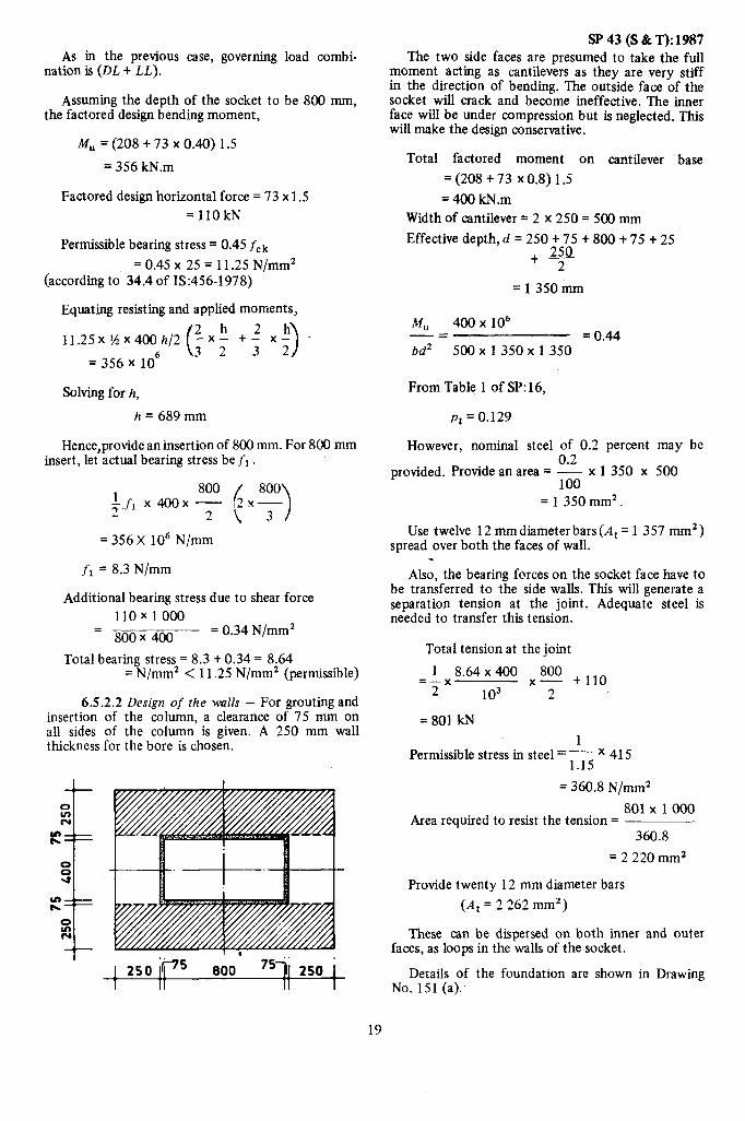
As in the previous case, governing load combi- nation is (DL + LL).
Assuming the depth of the socket to be 800 mm, the factored design bending moment,
M, = (208 + 73 x 0.40) 1.5
= 356 kN.m
Factored design horizontal force = 73 x 1.5 = 1lOkN
Permissible bearing stress = 0.45 fck
= 0.45 x 25 = 11.25 N/mm2 (according to 34.4 of IS:456-1978)
Equating resisting and applied moments,
11.25x%.~4OOh/2
= 356 x lo6
Solving for h,
h = 689 mm
Hence,provide an insertion of 800 mm. For 800 mm insert, let actual bearing stress be fr .
= 356 X lo6 N/mm
fr = 8.3 N/mm
Additional bearing stress due to shear force 110x1000
=----- 800 X 400 = 0.34 N/mm2
Total bearing stress = 8.3 + 0.34 = 8.64 = N/mm2 < 11.25 N/mm2 (permissible)
6.5.2.2 Design of the walls - For grouting and insertion of the column, a clearance of 75 mm on all sides of the column is given. A 250 mm wall thickness for the bore is chosen.
SP 43 (S & T): 1987 The two side faces are presumed to take the full
moment acting as cantilevers as they are very stiff in the direction of bending. The outside face of the socket will crack and become ineffective. The inner face will be under compression but is neglected. This will make the design conservative.
Total factored moment on cantilever base
= (208 + 73 x 0.8) 1.5
= 400 kN.m Width of cantilever = 2 x 250 = 500 mm
Effective depth, d = 250 t 75 t 800 t 75 t 25
+y
= 1350mm
M” 400 x lo6 -= = 0.44 bd2 500x1350x1350
From Table 1 of SP: 16,
pt = 0.129
However, nominal steel of 0.2 percent may be
provided. Provide an area = $ x 1 350 x 500
= 1350mm’.
Use twelve 12 mm diameter bars (A, = 1 357 mm2) spread over both the faces of wall.
. Also, the bearing forces on the socket face have to
be transferred to the side walls. This will generate a separation tension at the joint. Adequate steel is needed to transfer this tension.
Total tension at the joint
1 8.64~400 x_ +llo 800 =-_x 2 lo3 2
=801 kN 1
Permissible stress in steel = 11; x 415
= 360.8 N/mm2
801 x 1000 Area required to resist the tension =
360.8
= 2 220 mm2
Provide twenty 12 mm diameter bars
(A, = 2 262 mm’)
These can be dispersed on both inner and outer faces, as loops in the walls of the socket.
Details of the foundation are shown in Drawing No. 151 (a).
19

SP 43 (S & T): 1987 6.5.3 Design of Foundation for a Column with
Hinged Base - Even though the problem taken as illustration is one with fixed base column, the design of foundations for column with hinged base is also illustrated.
6.5.3.1 Case 1: Cast in-situ construction - Here, the foundation forces are taken from Table 81 for the frame with the same configuration but with a hinged base. Of course, in the case of column with hinged base, it is assumed that the footing as a whole will rotate relieving of the moments because of the compressibility of the soil. The case of structural hinge is not considered and it is not necessary to provide a structural hinge ai all.
The problem illustrated assumes a safe bearing capacity of soil of 100 kN/m2 .
Column size : 500 mmx 500 mm
Foundation forces at service load stage taken from Table 81 are reproduced below:
Load AxiaZ Force (kN) Shear Force
h fCompr&sion Tension’ (W
DL 191 - 41 LL 26 - 8 WL - 14 17
Totalaxialforce=191 t26=217kN
Assuming the self-weight of the foundation to be 10 percent of the above.
Area of bearing required = 217 x 1.1 -
100
= 2.4 m2 Ast = 9 x 79
Adopt a square footin of size,
16OOmmx1600mm
Upward bearing pressure on footing
217 =-
1.6x 1.6
= 85 kN/m2
a) Flexural design
Governing load case is (DL + LL)
Bending moment at the face of the column
o.552 =85x1.6 x -
2 = 20.6 kN.m
Ml 5 concrete and Fe 415 steel are used.
20
-ICAL SECTION FOR FLEXU?AL SHEAI?
Adopt an overall depth of 250 mm.
Therefore, effective depth, d = 250 - 40 - y - 12
=192mm
Therefore, %- = 20.6 x 1.5 x lo6
= 1.676 bd2 500 x 192’
From Table 1 of SP: 16,
Pt = 0.550 Beercent 0.550
A st= 100 - x500x 192 = 528 mm2
Provide nine 10 mm diameter bars in both direr tions.
= 706 mm’
Therefore, Pt 2 706
x 100 500 x 192
= 0.73 percent
b) Punching Shear
Dimensions of the critical section:
b = 500 t 192 = 692 mm 50
D = 200 t 550 x 454 = 241 mm
d=241-40- + -12=183mm
Punching shear
= 85 (1.6 x 1.6 - 0.692 x 0.692) = 176.9 kN

SP43(S&T):1987 Punching shear
= 176.9 x 1.5 x lo3 = 0.52 N/mm2
4x692 xl83
Permissible shear stress in punching = 0.25 Jfck
= 0.25 Ji?
= 0.97 N/mm’ > 0.52 N/mm’
Hence, it is O.K.
c) Flexural Shear
pt = 0.73 percent
From Table 13 of IS:456-1978
Design shear stress rC = 0.53 N/mm’
Dimensions at the critical section:
b=500+2 xl92=884mm
D = 232.5 mm
d = 232.5 - 58 = 174.5 mm
Flexural shear
= 85 x 1.6 x 0.358 = 48.7 kN
Nominal shear stress, 48.7 x 1.5 x lo3
v= 884 x 174.5
= 0.47 N/mm2 < 0.53 N/mm2
Hence, it is O.K.
The details of the reinforcement is shown in Drawing No. 156(b). A pedestal is provided since the development length in compression for 20 mm diameter bars is 905 mm.
6.5.3.2 Case 2: Precast column and cast m-situ foundation - Structural design of the foundation will be the same as that illustrated above. The walls of the socket is subjected to very small forces since there is no bending moment and hence only nominal rein- forcement is provided. The details of the reinforce- ment for the foundation are shown in Drawing No. 151 (b).
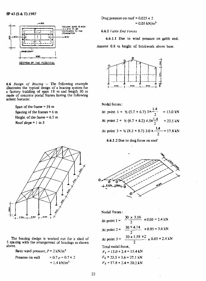
6.5.4 Design of a Pedestal - Where embedment below ground level of the columns has to be more than 500 mm because of firm soil available at greater depth, a pedestal can be provided. A typical design of the pedestal for 1200 mm height is illustrated below. The maximum height of pedestal should normally be limited to 1 200 mm.
21
Size of the column = 400 mm x 800 mm
Assume the size of the pedestal to be 600mmx 1 OOOmm
Since the DL + LL combination is governing the design.
Factored axial force, ~~=(l56tO.6xl.Oxl.2x25t26)1.5
=3OOkN
Factored bending moment,
M, = [167 t 41 t (58 t 15) 1.21 1.5 =443kN.m
4
PU 300 x103 = 0.02
fckbD 25 x600 x 1 000
MU 443 x lo6 a= = 0.03 f&D2 25 x 600 x(1 000)2
d’=40+11=51mm
d’ _ 51 -_ - = 0.5 D 100
From Chart 32 of SP:l6, P - =0.015 f ck
Therefore, P = 0.015 x 25 = 0.375 percent
Provide 0.5 percent of the cross-sectional area of the pedestal according to 33.4.3 of 13:456-1978.
Therefore, area of steel required
=0.005x600x 1 000=3000mm2
Provide eight 22 mm face. Provide 2 bars of longer face. Provide 8 centre-to-centre.
diameter bars, four on each 16 mm dia on each of the mm dia links at 300 mm
SP 43 (S & T): 1987
~m!_UMN EARS 10 4X20
SECTlON OF THE W.lESTAL
6.6 Design of Bracing - The following example illustrates the typical design of a bracing system for a factory building of span 18 m and length 30 m made of concrete portal frames having the following salient features :
Span of the frame = 18 m
Spacing of the frames = 6 m
Height of the frame = 6.5 m
Roof slope = 1 in 3
The bracing design is worked out for a shed of 5 spacing with the arrangement of bracings as shown above.
Basic wind pressure, P = 2 kN/m2
Pressure on wall = 0.7 p = 0.7 x 2
= 1.4 kN/m’
Drag pressure on roof = 0.025 x 2
= 0.05 kN/m2
66.1 Gable End Forces
6.6.1.1 Due to wind pressure on gable end.
Assume 0.8 m height of brickwork above base.
Nodal forces:
At point 1 = 1A (5.7 t 6.7) 3x: = 13.0 kN
At point 2 = ?4, (6.7 + 8.2) 4.5x+4 = 23.5 kN
1.4 At point 3 = ?4 (8.2 + 8.7) 3.0 x-= 17.8 kN
2
6.6.1.2 Due to drag force on roof
Nodal forces :
At point 1 = 30 2” 3*16 x0.05 = 2.4 kN
’ At point 2 3o 4.74 = x 0.85 = 3.6 kN 2
At point 3 30 x 1.58 x2 = x 0.05 = 2.4 kN 2
Total nodal force, or =13.0+2.4=15.4kN
F2 = 23.5 + 3.6 = 27.1 kN
F3 = 17.8 + 2.4 = 20.2 kN
22

SP43(S&T):1987
6.6.2 Force Diagram
2C-2 kN -
274 kN -
154 kN _-----
x X X T d A
1 6m i 1
In the ‘X bracing’, only one diagonal is normally considered as effective.
Diagonal force, P = F JGF-
a
Critical rafter bracing
F= 27.1 kN
27.1 kN
a=Bm’ I
P=27.1 dn
6
= 39.4 kN
Vertical bracing
a=6m
P= 15.4 &j.02+j.72
6
= 21.3 kN

SP43(S&T):1987 Since the rafter bracing and vertical bracing is not
in same plane, therefore, some additional stresses will come on portal rafters which can be rechecked, if required. Two alternatives have been worked out for design of bracing, one using steel and other using concrete.
6.63 Case 1: Steel bracing
a) Rafter bracing
Diagonal length = J6.322+ = 8.72 m
Axial force = 39.4kN
The tension diagonal member is designed and the same section is provided for the other diagonal. Consider two angles ISA: 50 x 50 x 6 mm placed back to back, with a 10 mm gusset.
Least slenderness ratio = L 872
=- = 354 r 2.46
which may be allowed.
Net area = 2 x 5.68 - 2 x 0.6 X 2.15 = 8.78 Cm2 *
Net axial capacity = 0.6 x 25 000 x 8.78 = 131.7 kN > 39.4 kN
/YA
50X50X6
‘t . 4-
b) Vertical bracing
Diagonal length = dG2 = 8.28 m Axial force = 21.3 kN
The tension diagonal member is designed and the same section is provided for the other diagonal. Consider two angles ISA:50 x 50 x 6 mm placed back to back with a 10 mm gusset.
Net axial capacity = 131.7 kN > 21.3 kN
Hence, it is O.K.
The details of the steel bracing designed above are shown in Drawing No. 154.
6.6.4 Case 2: Concrete Bracing- Use M 25 concrete and Fe 415 steel.
a) Rafter bracing
Axial force, P = 39.4 kN Factored axial force, Pu = 1.5 x 39.4 = 59.1 kN Consider cross-section of size 150 x 150 mm Self-weight acting vertically downwards
8.72 = 25 x 0.15 x 0.15 x -
6.00 = 0.82 kN/m
Bending moment at mid-height (span) due to self-weight
0.82 x 62 =-
8
= 3.7 kN.m .
Therefore, factored moment, M, = 1.5 x 3.7
= 5.6 kN.m
The compression member is designed and the same section is provided for the other diagonal also.
Pu (compression) = 59.1 kN
MU = 5.6 kN.m Effective length = 8.72 m
Additional facto;d moment due to slenderness,
where
PU = factoled axial road in compresslull, D = depth of cross-section at right angles to
major axis, and 1 ex = effective length in respect of the major
axis,
59.1 x 0.15 8.72 ’ Mu =
2000 ( 1 0.15
TotalM, = 5.6 + 15.0 = i5.0 kN.m = 20.6 kN.m
PU 59.1 x 10³ -=
f&hD 25 x150 x150 = 0.105
J+f” 20.6 x lo6 -= fckbD2 25x150~150~
= 0.244
24

SF 43 (S & T):1987 From Chart 34 of SP: 16,
P - = 0.20 fck '
p = 25 x 0.20
= 5 percent
5 Ati= - x150x 150
100
Therefore, adopt four 20 mm diameter bars as main reinforcement giving Ast = 1 256 mm2.
Adopt 6 $?r links at 150 centre-to-centre as trans- verse reinfcncement.
b) Vertical bracing
Axialforce,p= 21.3kN Factored axial force, I’” = 32.0 kN
Consider a cross-section of size 150 X 150 mm Self-weight acting vertically downwards
8.28 =25x0.15x0.15 x--;
6.00 = 0.78 kN/m
Bending moment at mid-height (span) due to self- weight
= 0.78 x ;
= 3.5 kN.m Factored moment, M, = 5.3 kN.m
The compression member is designed and the same section is provided for the other diagonal also.
Pu (compression) = 32.0 kN
WI i-5.3 kN.m
Effective length = 8.28 m Additional factored moment due to slenderness,
8.28 2 M ”
= 32.0x 0.15
2’.000 ( 1 0.15
= 7.3 kN.m
TotalM,, = 5.3 t 7.3 = 12.6 kN.m
From Chart 34 of SF: 16,
P
f,k = 0.12
PU 32.0 x10³ _-= = 0.057 f&bD 25 x 150 x 150
M” 12.6 x 10” _ =- = 0.149 fed@ 25 x 150 x 150s
P=25xO.12
= 3 percent
At = 3 x 150x 150 100
= 675mm2
Therefore, adopt four 16 mm diameter bars as main reinforcement giving Ast = 804 mm’.
Adopt 6 9 links at 150 centre-to-centre as trans- verse reinforcement.
The reinforcement and the connection details in the case of steel and concrete rafter bracing is shown in Drawing No. 154.
6.6.5 Gable End Columns
Height = 6.5 t’ f x 6 = 8.5 m
Factored moment in columns,
1.4~6~8.5~ =
8 ‘x 1.5 = 113.8 kN.m
Use 300 x 400 size columns,
Slenderness ratio = H = g - 28.33 D r.
Additional factored moment due to
slenderness = ’ 13*’ ’ o’3 8-5 ’ 0 23 = 4.6 kN.m 2000
Total I&, = 113.8 + 4.6 = 118.4 kN.m
Factored axial load, Pu (due to DL)
=‘0.3 x 0.4 x 8.5 x 25 x 1.5
= 38.25 kN
Mu 118.4 x 10” -= = 0.099 fck bD2 25 x300x 4002
P” 38.25 x 1 000 -= = 0.013 f&D 25x300~400
d’ = 4Otll =51
d’ 51 -= -=0.128 = 0.15 D 400
25

SP 43 (S & T): 1987 From chart 33, SP:16,
P
f,k = 0*07 P = 0.07 x 25 = 1.75 percent
1.75 A st =-x 300x400=2100mm2
100
Use six 22 mm diameter bars (At = 2 280 mm2) and 8 mm ‘stirrups at spacing
0.75 d = 0.75 x (400-51) = 260 mm centre-to-centre
I LOO I
I I
7. ESTIMATION OF QUANTITlES OF CONCRETE/ STEEL
7.1 Table 143 gives information about the material consumption according to the designs worked out for 140 portal frames, typified. For ease of comparison, the information is given in the form of volume of concrete per square metre of floor area and weight of steel per square metre of floor area.
In any given situation’ the column-free span required and height of the building are more or less fixed by the functional requirements of the shed. One important parameter that can be chosen by the designer is the spacing of the frame in the longi- tudinal direction. In almost all the crses worked out, it has been observed that the 12m spacing is more economical than the 6 m spacing. The difference in the cost is about 40 percent.
If one has to cover large areas, but at the same time if there is no restriction on the minimum column-free areas required, it is obvious that multi- bay portal frames will be cheaper than portal frames of single large span. From the data presented in the tables, it can be seen that the cost per square metre is less by about 15 percent when the large spins of 24 to 30 meters are sub-divided into 2 or 3 shorter spans.
8. SUMMARY AND CONCLUSIONS
8.1 Reinforced concrete portal frames without cranes have been analyzed for five different spans, four different’ column heights, two different spacings of
frames, three different roof slopes, two different support conditions for columns at the base (futed and hinged), three different wind zones with three possible wind actions and five different earthquake zones. Again the analysis has been worked out for single bay, two-bay, three-bay and four-bay portal frames. It has been found that because of the low rise of the buildings considered, forces in the members, even due to the lowest basic wind pressure of 1.0 kN/m’ were more than those due to the most severe earthquake zone forces. Furthermore, it was found that the governing design forces and moments in the members of the portal frames did not vary much with variation in wind zone or slope of the roof.
Total number of possible designs, considering all the above variables, could be as high as 17 280; too large number to be accommodated in any practicable typification scheme. Hence, typified designs have been worked out taking into account major para- meters like span, column height, spacing of frames, number of bays and type of support conditions as variables. Then the number of problems brought down to a reasonable limit of 140 cases. The other variables play only a minor role and their worst effects were taken into account.
The analysis results in the form of design forces and moments at various critical sections of the portal frames and foundation forces at service stage are given. The design results have been presented in the form of detailed drawings to enable ready execution. For the purpose of completeness, detailed draftings for 6 and 12 m span purlins, cladding runners, and their fixing details are also furnished.
For the benefit of those who prefer to adopt pre- fabrication technique to cast in-situ construction, possible location of joints and lifting points for all the cases have been given.
Typical illustrative designs have been worked out for purlins, cladding runners, frames, foundations and bracing. Also the quantity of concrete and steel per square metre of the plan area are worked out and presented.
The following conclusions can be drawn from analysis and design results, and also from quantities estimated :
a) It is found that in most of the frames the horizontal deflection at top of the column governs the design of members except for a few frames of large spans and smaller column heights.
b) Frames with fixed base give more economical designs compared to frames with hinged base by about 1 O-30 percent.
c) Multibay frames are more economical than single bay frames if there is no restriction regarding the unobstructed floor area.
d) Frames of spacing 12 m are generally found to be more economical than frames of 6.0 m spacing and the economy is about 40 percent.
26

SP43(S&T):1987 REFERENCES
1. IS:191 l-1967*Schedule of unit weights of build- concrete reinforcement: Part 1 Mild steel and ing materials @st revision) medium tensile steel bars. (third revision)
2. IS:875-1964t Code of practice for structural safety of building: Loading standards (revised)
8. IS:6006-1983 Uncoated stress relieved strand for prestressed concrete (first revision)
3.
4.
5.
6.
7.
IS:l893-1984 Criteria for earthquake resistant design of structures (fourth revision)
IS:456-1978 Code of practice for plain and reinforced concrete (third revision)
IS:1343-1980 Code of practice for prestressed concrete (first revision)
IS:1786-1985 High strength deformed steel bars and wires for concrete reinforcement (third revision)
IS:432 (Part 1) 1982 Mild steel and medium tensile steel bars and hard-drawn steel wire for
9.
10.
11.
12.
13.
AC1 Standard 318-1983 Building code require- ments for reinforced concrete. American Concrete Institute, Detroit, Michigan, USA
IS:800-1984 Code of practice for general cons- truction in steel (second revision)
1334326-1976 Code of practice for earthquake resistant construction of buildings (first revision)
IS:3007 (Part 1)1964 Code of practice for laying of asbestos cement sheetsPart 1 Corrugated sheets
SP:6(1)1964 IS1 Handbook for structural engineers : Structural steel sections (revised).
*Since revised as IS:875 (Part l)-1987
tSince revised as IS:875 (Parts 2 to 5)-1987
27

As in the Original Standard, this Page is Intentionally Left Blank

SP 43 (S &T):1987
TABLE 1 DESiGNFORCES
E Spar! : 9.0m
Frame spacing : 6.0m
Column height : 5.0m
Roof slopes : 1:3,1:4,1:5
Support condition : Fixed
Wind/seismic zones : All
Design Ultimate Forces :
Section Designation Bending Moment
(Hogging
Wm) (kM m)
Compressive Force Shear Force
WJ (WJ
A 70 - 37 -
B 61 - 56
C 61 50 - 45
D 20 33 - 23
E 16 46 - 12
.
Foundation Forces at Service Load Stage :
Section Designation Forces Due to
Bending Moment
(kN.mJ
Axial Force
%i&zrkz IkN) (WJ
Shear Force
lkN,
DL 10 47 - 9
A LL 9 13 - 5
WL 29 8 17
29

SP 43 (S & T):1987
bt%l : 9.0m I I E
Frame spacing : 6.0 m
Column height : 6.5 m
Roof slopes : 1:3,1:4,1:5
Support condition : Fixed
A Wind/seismic zones :All 1
1 m A I
Design Ultimate Forces : I 9.0 m
TABLE 2 DESIGNFORCES E
.- B
E u, 80
9 r- t
Section Designation Bending Moment
(
(kN.m) (kN:m)
Compressive Force Shear Force
f kN) (kN)
A 114 - 36 -
B 15 - 38
C 75 64 - 53
D 26 44 - 28
E 13 61 - 16
.
Foundation Forces at Service Load Stage :
Section Designation Forces Due to
Bending Moment
(kN.m)
Axial Force
w Compressive
(kN) (kN)
Shear Force
(kN)
DL 20 59 8
A LL 9 13 - 3
WL 29 - 21 31
30

SF’43(S&T):1987
TABLE 3 DESIGN FORCES
E
Span : 9.Om
Frame spacing : 12.0 m
Column height : 5.0m
Roof slopes : 1:3,1:4,1:5
Support condition : Fixed
Wind/seismic zones : All
Design Ultimate Forces :
Section Df3ignation Bending Moment Compressive Force Shear Force
’ Hogging Sagging (kkm)
A 153 95
B 143 - 131
c 143 88 106
D 34 19 - 55
E 22 109 - 23
. Foundation Forces at Service Load Stage :
Section Designation
A
Forces Due to
DL
LL
WL
Bending Moment
(kN. m)
4s
ia
51
Axial Force Shear Force
(kN1 (kN1 (k?J)
8.5 - 22
26 - 9
- 15 33
31
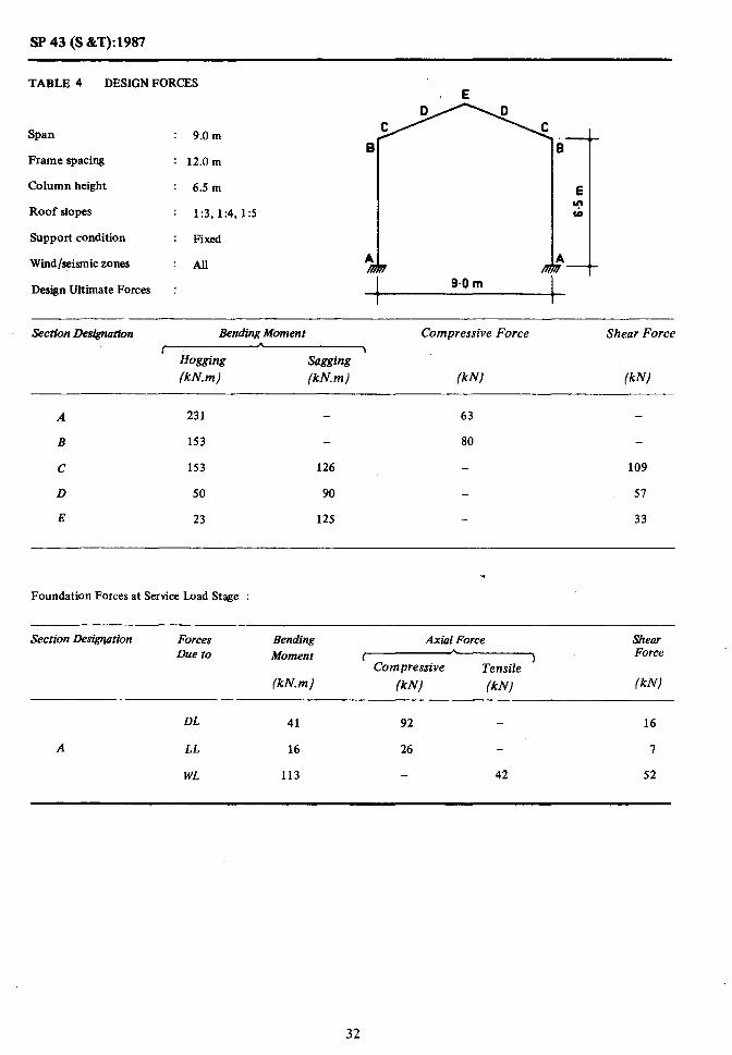
SP 43 (S &T):1987
TABLE 4 DESIGN FORCES
Span : 9.0 m I
Frame spacing
Column height
Roof slopes
Support condition
Wind/seismic zones
8 : 12.0m
: 6.5 m
: 1:3,1:4,1:5
: Fixed
: All
,- 3
E m W
4 ,-
t
Design Ultimate Forces : I 9.0 m c
Section Designation Bending Moment Compressive Force Shear Force
’ Hogging (kN.m)
Sagging ’ (kN.m) (k N) /kN)
A 231 - 63 -
B 153 - 80 -
c 153 126 - 109
D 50 90 - 51
E 23 125 - 33
Foundation Forces at Service Load Stage :
Section Desigrlation Forces Due to
Bending Moment
(kN.m)
Axial Force Shear I
b
Compressive 1 Force
Tensile
(kN1 (kN) (kN1
DL 41 92 - 16
A LL 16 26 - I
WL 113 - 42 52
32
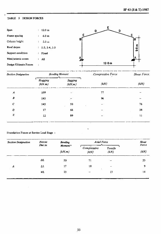
!sP43(S&T):1987
. TABLE 5 DESIGN FORCES
E Span : 12.0m
Frame spacing : 6.0m
Column height : 5.0m
Roof slopes : 1:3,1:4,1:5
Support condition : Fixed
Wind/seismic zones : All
Design Ultimate Forces :
Section Designation Bending Moment
(W
(kN. m) (kN.m)
Compressive Force Shear Force
(kN) (kNJ
A 109 - II
B 143 - 96 -
C 143 50 - 76
D 17 66 - 38
E 12 89 - 11
Foundation Forces at Service Load Stage :
Section Designation Forces Due to
Bending Moment 1
(kN.m)
Axial Force Shear .A
C 1 Force Compressive Tensile
(kN) (kNj (klv)
DL 50 71 - 23
A LL 17 18 _ 9
WL 23 - 13 14
33

SP 43 (S & T):1987
/ TABLE 6 DESIGN FORCES
Span
Frame spacing
Column height
Roof slopes
Support condition
Wind/seismic zones
Design Ultimate Forces
12.0 m a
6.0 m
6.5 m
1:3,1:4,1:5
Fixed
All
section Designation Bending Moment
7&y-7&$
(kN.m) (kMm)
Compressive Force Shear Force
(kN) (kN)
A 141 - 88 -
B 141 _ 96 -
c 141 68 18
D 2s 16 40
E 13 105 - 15
Foundation Forces at Service Load Stage :
Section Designation Forces Due to
Bending Moment
(kN.m)
Axtid Force Shear b
t ‘) Force
Compressive ‘Tensile
(kN) (kN1 (kN)
DL 46 78 18
A LL 16 18 - 6
WL 48 - 11 21
34
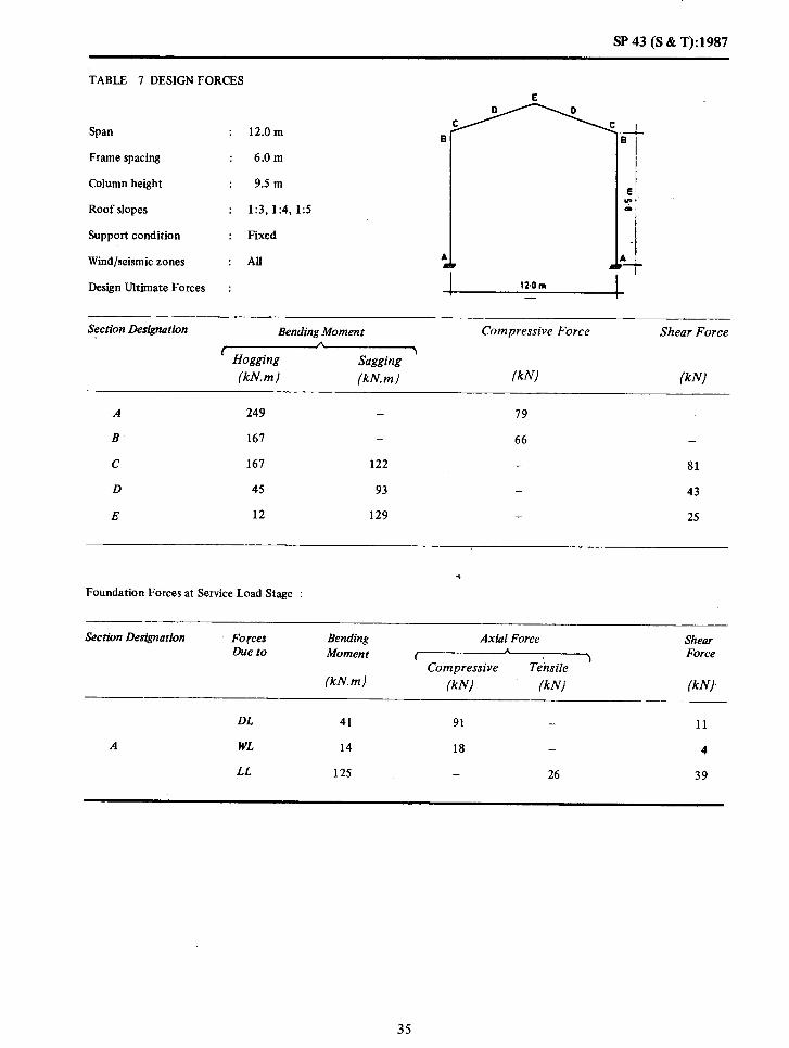
SP 43 (S & T): 1987
TABLE 7 DESIGN FORCES
Span : 12.0m 8
Frame spacing : 6.0m
Column height : 9.5 m
Roof slopes : 1:3,1:4, 1:5
Support condition : Fixed
Wind/seismic zones : All 1 1
Design Ultimate Forces : 12.om -
1
1. 3
El L”’ 01
%
Section Designation Bending Moment Compressive Force Shear Force
r I\
Hogging \
Sagging (kN.m) (kN.m) (kN) (kN1
A 249 - 79 -
B’ 167 - 66 -
C 167 122 - 81
D 45 93 - 43
E 12 129 - 25
,
Foundation Forces at Service Load Stage :
Section Designation Forces Due to
Bending Moment
(kN.m)
Axial Force Shear
I L Force
Compressive Teksile j
f kNl f k Nl (kNl,
DL 41 91 - 11
A WL 14 18 - 4
LL 125 - 26 39
35

W43(S&T):W37
TABLE 8 DESIGN FORCES
Span : 12.0m
Frame spacing : 12.0m E
Column height : 5.00m
Roof slopes : 1:3,1:4,1:5
Support condition : Fixed
Wind/seismic zones : All
Design Ultimate Forces :
Section Designation Bending Moment Compressive Force Shear Force ( j
Hogging Saggng (RN.?) (kN.m) (kN.I (kN)
A 198 - 112
B 258 - 174 -
C 258 117 137
D 41 118 68
E 35 161 23
Foundation Forces at Service Load Stage :
Section Designation
A
Forces Due to
DL
LL
WL
Bending Moment
(kN.m)
86
35
46
Ax&l Force shear A ( > Force
Compressive Tensile
(kN) (klv/ WI
106 40
35 17
25 27
36 .

SP43(S&T):1987
TABLE 9 DESIGN FORCES
Span : 12.0m
Frame spacing : 12.0m E
Column height
Roof slopes
Support condition
Wind/seismic zones
Design Ultimate Forces
: 6.5 m
: 1:3, 1:4, 1:5
: Fixed
: All
:
Section Designation Bending hiomen t Compressive Force Shear Force c 1
Homing &c@ng (kN.m) (kN. m) (kN) (kN)
A 264 - 125 _
B 255 174 -
c 255 152 - 141
D 58 137 - 73
E 42 190 - 30
Foundation Forces at Service Load Stage :
Section Designation Forces Due to
Bending Moment
(kN.m)
Axial Force Shear C
* 1 Force
Compressive Tensile
(kN) (kN) (kN)
DL 81 113 - 30
A LL 32 35 _ 13
WL 96 - 21 43
37

SP 43 (S 8c T): 1987
TABLE 10 DESIGN FORCES
Span : 12.0m E
Frame spacing : 12.0m
Column height : 9.5 m
Roof slopes : 1:3,1:4,1:5
Support condition Fixed
Wind/seismic zones : All
Design Ultimate Forces :
Section Designation Bending Moment Compressive Force Shear Force
(kN.m) (kN.m) f kNl IkAY
A 483 93 -
B 309 - 113 -
c 309 259 - 146
D 101 168 - 77
E 39 232 _ 50
Foundation Forces at Service Load Stage :
Section Designation
_
Forces Due to
Bending Moment
(kN.m)
Axial Force Shear
I 1 Forces Compressive Tensile
Ml WI WV
DL 71 121 - 20
A LL 28 35 - 8
WL 251 - 52 79
38
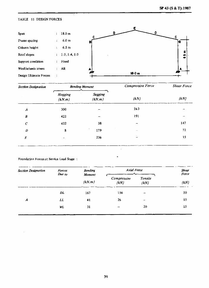
SP 43 (S & T): 1987
TABLE 11 DESIGN FORCES
Span : 18.0m
Frame spacing : 6.0m e
Column height : 6Sm
Roof slopes : 1:3,1:4,1X5
Support condition : Fixed
Wind/seismic zones : All A A
Design Ultimate Forces :
E
Cl C c
A 7 18-O m
Section Designation Bending Moment Compressive Force Shear Force h
I \ Hogging Sagging
(kN.m) (kN.m) (kN) (kN)
A 300 - 243 -
B 422 - 191 -
C 422 38 - 147
D 8 179 _ 72
E - 236 _ 15
-
. Foundation Forces at Service Load Stage :
Section Designation Fore es Due to
Bending Moment
(kN.m)
Axial Force Shear A
I .I Force Compressive Tensile
f kN) lkN) lkN)
DL 167 156 - 50
A LL 41 26 - 15
WL 31 - 20 15
39

SP43 (S&T):l!%Q
TABLE 12 DESIGN:~0RCES
Frame spacing
Column height
Roof slopes
Support condition
Wind/seismic zones
Design Ultimate Forces
: 18.0 m
6.0 m
9.5 m
1:3,1:4,1:5
Fixed
0
; 1
,,.,
1 18.0 m
I 7 E Y-1 Q
! 4
Section Designation Bending Moment
IHogging--- Sagging (kN.m) (kN.m)
Compressive Force Shear Force
(kNl (kN)
A 319 - 212 -
B 421 - 191
C 421 86 - 154
D 21 222 - 19
E _ 308 - 21
Foundation Forces at Service Load Stage :
Section Designation Forces Due to
Bending Moment
(kN.m)
Axial Force
V Compressive
(klvl (klvl
Shear Force
(kNl
DL 152 180 - 39
A LL 36 26 - 10
WL 101 - 16 31
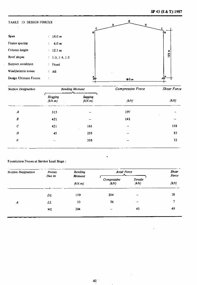
SP 43 (S & T): 1987
TABLE 13 DESIGN FORCES
C
Span
Frame spacing
Column height
Roof slopes
Support condition
Wind/seismic zones
Design Ultimate Forces
: 18.0 m
: 6.0m
: 12.5 m
: 1:3,1:4,1:5
: Fixed
: All
: la.0 Ill 1
+
E
x
j \
Section Designation Bending Moment
( (kN.m) (kN. m)
Compressive Force Shear Force
(kN) (kN)
A 515 - 191 .-
B 421 - 141 -
C 421 161 158
D 45 258 - 83
E - 358 - 32
.
Foundation Forces at Service Load Stage :
Section Designation
A
Forces Due to
DL
LL
WL
Bending Moment
(kN. m)
139
33
204
Axial Force
(T&zYYz (kN) (kN)
204
26 -
- 43
Shear Force
(kN)
28
I
49
41

W 43 (S & T): 1987
TABLE 14 DESIGN FORCES
Frame spacing
Column height
Roof slopes
Support condition
Wind/seismic zones
Design Ultimate Forces
: 18.0m
: 12.0 m
: 6.5m
: 1:3,1:4,1:5
: Fixed
: All
:
L
0 C C
-‘---r E o- i
A A + 18-O m
1
Section Designation Bending Moment
(Hoasinp W.4 (kN.m)
Compressive Force Shear Force 1
(kN) (kN)
A 419 - 362
B 681 - 301
C 681 174 - 236
D 52 288 116
E 36 381 - 30
,
Foundation Forces at Service Load Stage :
Section Designation Forces Due to
Bending Moment
(kn! m)
Axial Force Shear *
’ Compressive Tensile ’ Force
(kN) (kN (kN)
DL 252 210 - 81
A LL a2 52 30
WL 62 - 40 29
42

SP 43 (S & T): 1987
I 8 Span : 18.0 m
Frame spacing : 12.0 m
Column height : 9.5 m
Roof slopes : 1:3,1:4,1:5
Support condition : Fixed
Wind/seismic zones :All I
Design Ultimate Forces : I I
TABLE 15 DESIGNFORCES
18.0 m
Section Designation Bending Moment Compressive Force Shear Force L 1
Hogging sagging (kN. m) (kN. m) (kN) fkN)
A 646 - 268 -
B 618 - 307 -
c 678 271 - 248
D 94 358 - 128
E 42 496 - 43
. Foundation Forces at Service Load Stage :
Section Designation Forces Due to
Bending Moment
(kN. m)
A&l Force
V Compressive (kN) ikN)
Shear Force
lkN)
DL 229 234 - 59
A LL 73 52 - 20
WL 202 - 32 62
43

Sp 43 (S &T):1987
TABLJ? 16 DESIGNFORCES
Span : 18.0 m
Frame spacing : 12.0m
Column height : 12.5 m
Roof slopes : 1:3,1:4,1:5
Support condition : Fixed
Wind/seismic zones : All
Design Ultimate Forces :
.
, 18.0 In A
Section Designation Bending Moment Compressive Force Shear Force A
r Hogging sOgg.ng
J
&N-m) (kN. m) (kN) lkN)
A 928 _ 213 -
B 683 - 205 -
C 683 411 - 255
D 149 416 - 134
E 38 511 - 62 *
Foundation Forces at Service Load Stage :
Section Designation Forces Due to
Bending Moment
(kN. m)
Axial Force Shear
( A
) Force Compressive Tensile
lkN) /kN) lkN)
DL 210 258 - 43
A LL 66 52 - 14
WL 409 - 86 98
44

SP43(S&T):1987
TABLE 17 DESIGN FORCES
Span
Frame spacing
Column height
Roof slopes
Support condition
Wind/seismic zones
Design Ultimate Forces : I 244 m
24.0 m
6.0 m
9.5 m
1:3, 1:4, 1:s
Fixed
AII
Section Designation Bending Moment Compressive Force Shear Force 1
Ho&w (kN. m) (W WJ
A 724 - 377
B 989 - 334
C 989 - - 260
D - 440 - 129
E - 592 24
Foundation Forces at Service Load Stage : .
Section Designation Forces Due to
Bending Moment
(kN. m)
Axial Force
(Compressive @NJ &YJ
Shear Force
WJ
DL 405 313 - 90
A LL 71 35 18
WL 77 - 26 24
45
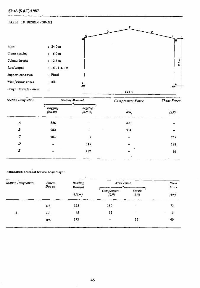
SP-43 (S &T):1987
TABLE 18 DESIGNFORCES E
Span
Frame spacing
Column height
Roof slopes
Support condition
Wind/seismic zones
: 24.0m
: 6.0 m
: 12.5 m
: 1:3,1:4,1:5
: Fixed
: AU 1 A A
Design Ultimate Forces : 2kOm
I
I I
Section Designation Bending Moment Shear Force
(Hogging
Compressive Force
Wm) --
(kN. m) -
(kN) (kN)
A 826 - 423 -
B 982 - 334 -
c 982 9 - 269
D - 515 - 138
E - 712 - 26 .
Foundation Forces at Service Load Stage :
Section Designation
A
Forces Due to
DL
LL
WL
Bending Moment
(kn! m)
378
65
173
Axial Force
(compressiveTensile (kN) (k N)
350
35 _
22
Shear Force
(kN)
73
13
40
46

SP 43 (S & T): 1987
TABLE 19 DESIGNFORCES
Span : 24.0m
Frame spacing : 12.Om
Column height : 9.5 m
Roof slopes : 1:3,1:4,1:5
Support condition : Fixed
Wind/seismic zones :AB
Design Ultimate Forces :
Sectiok Designation Bending Moment Compressive Force Shear Force A
1 ‘) Hogging kg& (kN. m) Wm) (klv! (kN)
A 1062 - 444 -
B 1450 - 489 -
C 1450 197 - 381
D 47 645 189
E 868 - 40
Foundation Forces at Service Load Stage :
Section Designation Forces Due to
Bending Moment
Wm)
Axial Force Shear
r h
1 Force Compressive Tensile
(klvl (kN) (kN
DL 553 384 - 134
A LL 141 70 - 37
WL 155 52 48
47

SP43(S&T):1987
TABLE 20 DESIGNFORCES
Span : 24.0 m
Frame spacing : 12.0 m
Column height : i2.5 m
Roof slopes : 1:3,1:4,1:5
Support condition : Fixed
Wind/seismic zones : All
Design Ultimate Forces :
Section Des&don Bending Moment Compressive Force Shear Force
r n
3 Hogging sagg’ng (kn! m) (kN.m) liklvl (klv)
A 1 293 491 -
B 1440 489 -
C 1440 333 - 395
D 90 154 - 283
E 1043 - 55
.
Foundation Forces at Service Load Stage :
Section Designation Forces Due to
Bending Moment ’
(kn! m)
Axial Force
( (kW lklvl
Shear Force
Ik f+!)
DL 516 421 100
A LL 130 70 - 21
WL 346 - 44 80
48

SP 43 (S & T): 1987
TABLE 21 DESIGNFORCES
Span : 30.0 m
Frame spacing : 6.0m
Column height : 9.5m El Hi Roof slopes
i! : 1:3,1:4,1:5
; Support condition : Fixed A I
.T Wind/seismic zones :All
30.0 m I Design Ultimate Forces : i .-
Section Designation Bending Moment Compressive Force Shear Fo%e A , >
Hogging sagging (kN. m) Wm) (klvl iklvl
A 1 141 - 542 -
B 1 523 - 417 -
C 1523 - - 313
D 600 - - 150
E - 765 - 43
Foundation Forces at Service Load Stage : .
Section Designation Forces Due to
Bending Moment
(kn! m)
Axial Force
(Complesslve
iklv) (kW
Shear Force
(k fV
DL 662 361 - 152
A LL 119 44 - 29
WL 45 - 35 16
49
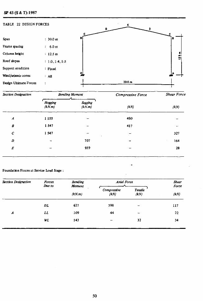
SP 43 (S & T): 1987
TABLE 22 DESIGNFORCES E
Span
Frame spacing
Column height
Roof slopes
Support condition
Wind/seismic zones
: 30.0 m a
: 6.0m
: 12.5 m
: 1:3,1:4,1:5
: Fixed
:All :
Design Ultimate Forces : I 30.0 m I
Sectdon Designation Bending Moment Compressive Force Shear Force
I A Hoggiig sagg+lg
1
(kN. m) (kN.m) (kN) (kN)
A 1 155 480 -
B 1541 417
c 1 541 - 321
D 101 164
E - 959 28
Foundation Forces at Service Load Stage :
Section Designation
A
Forces Due to
DL
LL
WL
Bending Moment
(kN. m)
621
109
143
Axial Force
7 (kN) /kN)
398 -
44
32
Shear Force
(kN)
117
22
34
50

SP 43 (S & T): 1987
TABLE 23 DESIGNFORCES
0 0
Span : 30.0m Ie
C 0
Frame spacing : 12. Om
Column height : 9.5 m :I E Ln 6,
Roof slopes : 1:3,1:4,1:5
Support condition : Fixed A -i
A
Wind/seismic’zones :All 3o.u m / I
Design Ultimate Forces :
Section Designation Bending Moment Compressive Forck Shear Force
(& (kN)
A 1664 732 -
B 2 233 - 611 -
C 2 233 214 - 459
D 48 880 219
E - 1 122 - 62
-.
.
Foundation Forces at Service Load Stage :
Section Designaiion Rvces Due to
Bending Moment
(kN.m)
Axial Force
I
(kN1 (kNl
Shear Force
(kN)
DL 905 450 - 215
A LL 237 87 - 59
WL 90 - 70 32
51

SP 43 (S &T): 1987 .
TABLE. 24 DESIGN FORCES E
I
: 30.0m
Frame spacing
Column height
Roof slopes
Support condition
: 12.0m
: 12.5 m
: 1:3,1:4,1:5
: Fixed J A A n
Wind/seismic zones .: All
Design’Ultimate F&es : I 30.0 m
i
Section Designation Bending Moment
(Hogging (klv m) (kN.m)
Compressive Force
(kN)
Shear Force
(k N)
A 1715 _ 566 -
B 2268 - 611 -
C 2268 338 - 480
D 83 1 036 - 240
E - 1405 - 52
Foundation Forces at Service Load Stage :
Section Designation
A
Forces Due to
DL
LL
WL
Bending Moment
(kN. m)
857
218
286
Axial Force
Tzjz?Yz
(kN) (k N)
487 -
87 -
- 64
Shear Force
(kN)
159
43
67
52
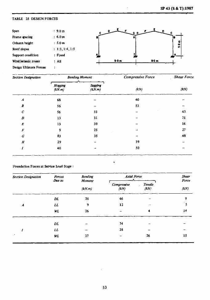
!P 43 (S & T):l987
TABLE 25 DESIGN FORCES
Span : 9.0m
Frame spacing : 6.0m
Column height : 5.0m
Roof slopes
Support condition
Wind/seismic zones
:All :;j
: 1:3,1:4,1:5
: Fixed
I s.0 m I 90m I I I I Design Ultimate Forces :
Section Designation Bending Moment Compressive Force Shear Force
v (kN. m) (kN.m) (kN) (kN)
A 68 40
B 56 53
c 56 33 43
D 13 31 - 21
E 13 39 - 16
F 9 25 27
G 83 35 48
H 29 39 I 40 50 -
Foundation Forces at Service Load Stage : .
Section Des&nation
A
Forces Due to
DL
LL
WL
Bending Moment
(kN.m)
20
9
26
Ax121 Force Shear Force
(kN) (kN) (kN)
46 9
12 5
- 4 14
DL 14 - -
I LL 28 -
WL 21 - 26 15
53

. SP43(S&T):1987
TABLE 26 DESIGNFORCES
Span : 9.0 m
Frame spacing : 6.0 m
Column height : 6.5 m
Roof slopes : 1:3,1:4,1:5
Support condition : Fixed
Wind/seismic zones :All
Design Ultimate Forces :
Section Designation Bending Moment Compressive Force Shear Force
r A
Hogging Sagging 1
(kN.m) (kn! m) (kN1 (kN)
99 - 36 -
70 - 39 -
70 40 48
13 40 - 23
10 49 - 19
8 39 - 33
101 29 - 58
50 - 56 -
64 - 78 -
Foundation Forces at Service Load Stage :
Section Designation Forces Due to
Bending Moment
(kN.m)
Axial Force
w Compressive /kNl /kNI
Shear Force
lkN)
DL 20 57 7
A LL 8 12 - 3
WL 46 - 19 21
DL - 93 - -
Z LL - 28 - -
WL 43 - 26 19
54
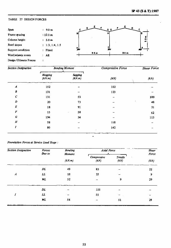
SP43 (S&T):1987
TABLE 27 DESIGNFORCES
Span : 9.0m
Frame spacing : 12.0 m
Column height : 5.0m
Roof slopes : 1:3,1:4,1:5
Support condition : Fixed
Wind/seismic zones s.om 9.0 m
: All I I I I 1 I
Design Ultimate Forces :
Section Designation Bending Moment
rHogging_ (kn! m) (kN.m)
Compressive Force Shear Force
(kN1 FNI
152
131
131
20
18
15
194
58
80
102
123
53 -
13 -
91
58 -
54 -
118
-
100
48
31
62
113
-
142 -
.
Foundation Forces at Service Load Stage :
Section Designation Forces Due to
Bending Moment
(kN. m)
Axial Force Shear
1 A 1 Force
Compressive Tensile (kN) /kN) (kNj
--
DL 49 83 22
A LL 18 25 - 9
WL 52 9 29
DL - 155
I LL - 55 - -
WL 54 - 51 29
55

SF’43(S&T):1987
TABLE 28 DESIGNFORCES
Span : 9.0m
Frame spacing
Column height
Roof slopes
Support condition
Wind/seismic zones :All I Mm I m.om I I I ,
Design Ultimate Forces :
Se&bon Designation Bending Moment Compressive Force Shear Force A
( I Hogging Sagging (kNm) (khJ.m) (kN) (kN
A 201 64
,B 143 - 82
C 143 78 100
D 25 83 48
E 18 102 38
68 F 15 69 -
G 209 54
H 99 112 -
119
I 129 153 -
.
Foundation Forces at Service Load Stage :
Section DesipMtion Forces Due to
Bending Moment
(kh? m)
Axial Force
[Comprersive (klvl (klvl
Shear Force
(klv:,
DL 42 88 - 16
A LL 16 24 - 6
WL 92 31 42
DL - 162 - -
I LL 56 - -
WL 86 - 52 31
56

SP 43 (S c&T):1987
TABLE 29 DESIGNFORCES
Span
Frame spacing
Column height
Roof slopes
S*ort condition
&nd/seismic zones
De&n Ultimate Forces :
: 12.0m
;;:;; ;;j
: 1:3,1:4,1:5
: Fixed L 1 120 m I 12.Q m I
: AU
Section Designation Bending Moment Compressive Force Shear Force
f A
‘) Hogging sagging (kN. m) (kN.m) (kN) (kN)
A 127 - a4 -
B 137 93
c 137 29 - 73
D 13 60 - 35
E 10 76 17
F 10 48 _- 41
G 174 35 79
H - 199
I - 223
Foundation Forces at Service Load Stage :
Section Designation Forces Due to
Bending Moment
(kn! m)
Axial Force Shear Force
(kN) (kN) (kN)
DL 58 70 25
A LL 19 17 9
WL 27 8 14
DL - 149 - -
z LL - 36 - -
WL 29 - 34 15
57

SP 43 (S & T):l!B7
TABLE 30 DESIGN FORCES
c E Span : 12.0m
Frame spacing : 6.0m
Column height : 6.5m
Roof slopes : 1:3,1:4,1:.5
Support condition : Fixed
Wind/seismic zones :All
Design Ultimate Forces : I
Section Designatioh Bending Moment
(Hogging (kN. m) (kn! m)
Compressive Force Shear Force
(kN) iklvl
A 143 92 -
B 130 - 91 -
C 130 39 - 13
D 14 IO - 36
E 11 80 20
F 10 54 - 46
G 190 37 - 83
H 49 - 99
Z 68 ,130 -
.
Foundation Forces at Service Load Stage :
Section Designation Forces Due to
Bending Moment
(kn! m)
Axial Force Shear A
( 1 Force Compressive Tensile
/kN) (klv! f klvl
DL 51 16 - 18
A LL 17 17 6
WL 44 - 6 18
DL - 129 -
Z LL - 31
WL 46 - 34 19

SP 43 (S & T): 1987
TABLE 31 DESIGNFORCES
Span : 12.0m
Frame spacing : 6.0m
Column height : 9.5 m
Roof slopes : 1:3,1:4,1:5
Support condition : Fixed
Wind/seismic zones :All
Design Ultimate Forces :
E E 0 F F D
c GG C
B il n e
E’. ‘2
I & i I 12.0 m I 1 1. 12’0n i
Section Designation Bending Moment
(Hogging (kN. m) (kN.m)
Compressive Force Shear Force
ikN) (kN)
A 211 _- 71 -
B 149 - 65 -
C 149 15 73
D 20 86 36
E 10 103 - 27
F 13 70 - 51
G 211 35 - 89
H 107 103
I 136 - 148 -
.
Foundation Forces at Service Load Stage :
Section Designation Forces Due to
Bending Moment
(kn! m)
Axial Force Shear
I 1 Force
Compressive Tensile ’ fkN) /kN) (kN)
DL 41 88 11
A LL 13 16 4
WL 100 24 31
DL - 146 -
Z LL - 38 -
WL 90 35 27

SP 43 (S&T):1987
TABLE 32 DESIGN FORCES
spa : 12.0m
Frame spacing : 12.0m
Column height : 5.0m
Roof slopes : 1:3,1:4,1:5
Support condition : Fixed
;;j
Wind/seismic zones : All I 1 12.0 m I 12.0 m I 8
Design Ultimate Forces :
Section Designation Bending Moment Compressive Force Shear Force A
I b ffoslping %giig fkN m) (kN. m) (klv) lkW
232
241
241
32
29
25
314
51
a1
125
168 -
13 - 131
108 63
131 _I 34
88 14
91 142
154
118
,
Foundation Forces at Service Load Stage :
Section Designation Forces Due to
Bending Moment
(klv. m)
Axial Force Shear 1
‘Corn presive Tensile’ Force
(klvl FW IkN
DL 100 104 - 43
A LL 38 34 18
WL 54 - 15 28
DL - 193
I LL 12
WL 58 61 30

SP 43 (S & T): 1987
TABLE 33 DESIGNFORCES
L L
Span : 12.0m
Frame spacing : 12.0m B
Column height : 6Sm
Roof slopes : 1:3,1:4,1:5
Support condition : Fixed * I
Wind/seismic zones : All
Design Ultimate Forces :
Section Designation Bending Moment
IHogging (kN. m) (kN. m)
I? ompressive Force Shear Force
(kN) (kN)
265
234
234
36
32
26
344
91
137
- 134 -
- 165 -
92 - 133
127 - 64
189 - 40
101 - 82
95 - 150
- 158 -
- 189
Foundation Forces at Service Load Stage :
Section Designation Forces Due to
Bending Moment
(kN. m)
Axinl Force
I Compressive (kN) (kN)
______
Shear Force
(kN)
DL 89 110 - 31
A LL 33 33 12
WL 88 - 12 31
DL - 203 - -
Z LL - 74 -
WL 91 - 68 38
61

SP43(S&T):1987
TABLE 34 DESIGNFORCES E E D F F 0
C GG C
a H Sean
B : 12.0m
Frame spacing : 12.0m 4t
Column height : 9.5 m E.
Roof slopes : 1:3,1:4,1:5
Support condition : Fixed
Wind/seismic zones : All * I
I 12.om 1 12.0m
Design Ultimate Forces :
Section Des&nation Bending Moment I
A ,
Compressive Force Shear Force
’ Hogging Sagging ’ (kN. m) (kN. m) iW
407
274
274
49
32
30
381
214
271
- 91
- 112 -
162 - 132
154 - 64
186 - 54
130 - 93
95 - 161
165 -
- 210 -
Foundation Forces at Service Load Stage :
Section Designation
A
Forces Due to
DL
LL
WL
Bending Moment
(kN. m)
71
26
201
Axial Force
v (kN) (kN)
121 -
32 -
47
Shear Force
(kN) -
18
7
63
DL - 222 - _
I LL - 76 -
WL 181 - 69 54
62

SP 43 (S & T): 1987
TABLE 35 DESIGN FORCES
Span
Frame spacing
Column height
Roof slopes
Support condition
Wind/seismic zones
Design Ultimate Forces
: 18.0m
: 6.0m
: 6.5m
: 1:3,1:4, I:5
: Fixed
: All
:
Section Des&nation Bending Moment Compressive Force Shear Force
’ Hogging Sagging ’ (kN. m) (kN.m) lkN) (kN)
A 351 242 -
B 412’ - 187 -
C 412 5 - 142
D 7 162 - 67
E - 201 - 23
F 3 135 - 75
G 487 6 - 150
H - - 390 -
I 77 - 295 -
Foundation Forces at Service Load Stage :
Section Designation Forces Due to
Bending Moment
(kN. m)
A.&l Force
m Compressive (kN) IkN)
Shear Force
fkfl)
DL 198 156 - 63
A LL 47 26 - 16
WL 47 - 12 18
DL - 262 - _
I LL - 54 - -
WL 51 50 20
63
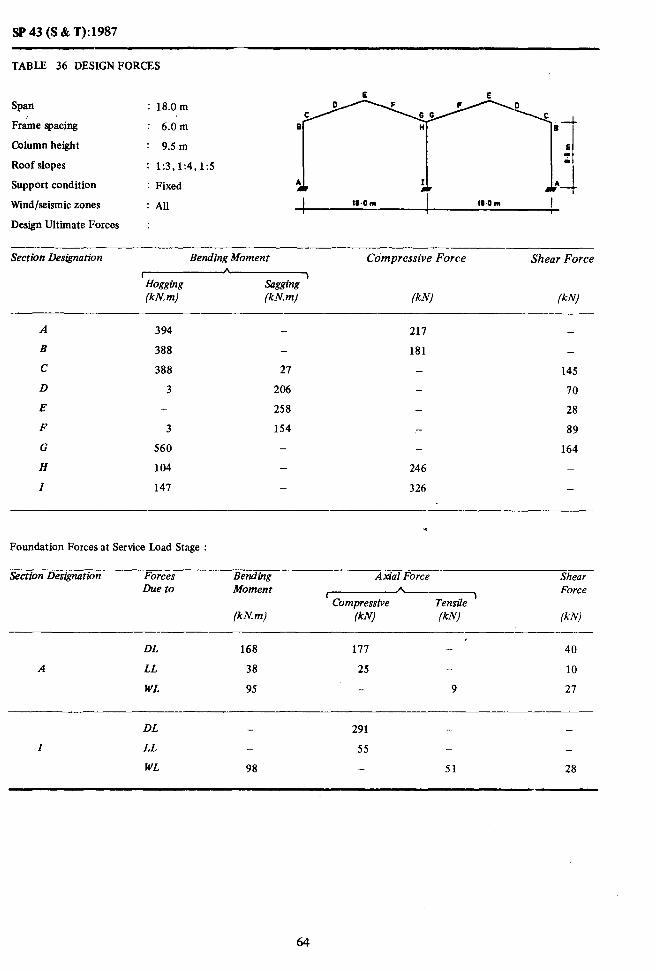
SP 43 (S & T):1987
TABLE 36 DESIGNFORCES
Span : 18.0m
Frame spacing : 6.0m
Column height : 9.5 m
Roof slopes
Support condition
r;i’r;“rl
: 1:3,1:4,1:5
: Fixed
Wind/seismic zones : All I 18.0 m 18.0 II)
Design Ultimate Forces :
Section Des&nation Bending Moment
lHogglng (kN. m) (kN.m)
Compressive Force
IkN)
Shear Force
(kN) -
A 394 - 217 -
B 388 - 181 -
c 388 27 - 145
D 3 206 IO
E - 258 - 28
F 3 154 - 89
G 560 - 164
H 104 - 246 -
I 147 - 326 -
.
Foundation Forces at Service Load Stage :
Section Designation
A
Forces Due to
DL
LL
WL
Bending Moment
(kN. m)
168
38
95
Azdal Force Shear
r h Force Compressive Tensile
)
(kN) lkN) (kN) --
I 111 - 40
25 - 10
- 9 21
DL - 291 -. -
I LL - 55 - -
WL 98 - 51 28
64

SP 43 (S & T):1987
TABLE 37 DESIGNFORCES
Span : 18.0m
Frame spacing : 6.0m
Column height : 12.5 m
Roof slopes : 1:3,1:4,1:5
Support condition : Fixed
Wind/seismic zones : All
Design Ultimate Forces :
Section Designation Bending Moment Compressive Force Shear Force A
c 7 Hogging sagging (kN.m) (kN.m) /kNj (kN)
467
396
396
5
-
3
, 606
184
240
- 196 139 -
18 - 145
239 - 71
292 - 35
176 - 98
- - 173
- 253 -
- 358
.
Foundation Forces at Service Load Stage :
Section Designation Forces Due to
Bending Moment
(kN. m)
Axial Force Shear
(Compressive ) Force
Tensile lkN) lk N! (kN),
DL 144 199 - 27
A LL 32 24 - 7
WL 168 - 38 40
DL _ 320 - -
I LL - 56 - -
WL 160 _ 52 36
65

SP 43 (S &T):1987
TABLE 38 DESIGN FORCES
span
Frame spacing
. .on_
Support condition
i fiy,lr5 r-T=-={
WOm
Wind/seismic zones I*OIll
: All 4 1 I I 1
Design Ultimate Forces :
Column height
Roof slopes
Section Designation Bending Moment Compressive Force Shear Force A
I Hogging &l (kN m) (kN.m) lkN) (k N)
--.
A 591 - 253 -
B 664 - 301
C 664 106 - 228
D 45 260 - 108
E 28 323 - 45
F 31 218 - 121
G 784 124 - 241 H 628 I 154 _ 380 -
.
Foundation Forces at Service Load Stage :
Section Designation Forces Due to
Bending Moment
(kN m)
Ax&l Force Shear
c A P~mnro.r;.,o T”..“,V,, J Force b”S’.Y, cY*,“c 1 cr‘w‘s
(kN) IkN (kW
DL 299 209 95
A LL 93 51 32
WL 95 - 25 35
DL 369 - _
I LL - 107 -
WL 103 - IN 39

SP 43 (S &T):1987
TABLE 39 DESIGNFORCES
Span : 18.0m
Frame spacing : 12.0m
Column height : 9Sm
Roof slopes
Support condition
Wind/seismic zones
: 1:3,1:4,1:5 A I A
: Fixed 1 1 l-i 18.0 m IO.0 m
:Au I
Design Ultimate Forces :
Section Designation Bending Moment
lHogging (kN. m) (kN.m)
Compressive Force
(kN)
Shear Force
(k Nl
A 665
B 625
c 625
D 49
E 33
F 38
G 903
H 208
Z 294
- 281 -
_ 292 -
144 - 234
332 - 113
416 - 58
256 _ 144
131 264
- 335 -
_ 415 -
. Foundation Forces at Service Load Stage :
Section Designation
A
Forces Due to
DL
LL
WL
Bending Moment
(kN. m)
254
15
189
Axial Force
(Compressive (kNl (kN)
229 -
50 -
- 19
Shear Force
(kN)
60
19
54
DL - 401 - -
Z LL - 110 - -
WL 196 - 102 55
67

SP 43 (S &T): 1987
TABLE 40 DESIGNFORCES
Span : 18.0m
Frame spacing : 12.0m
Column height : 12.5 m
Roof slopes : 1:3,1:4,1:5
Support condition : Fixed
Wind/seismic zones : AU
Design Ultimate Forces :
Section Designation Bending Moment
CHogging (kN. m) (kN. m)
Compressive Force Shear Force
(kN) (kN)
A 828 - 214 _
B 646 - 201 -
C 446 244 234
D 60 384 114
E 31 410 71
F 38 299 _- 158
G 971 128 - 278
H 367 - 342 _
I 480 - 449 -
.
Foundation Forces at Service Load Stage :
Section Designution Forces Due to
Bending Moment
(kN. m)
Axial Force Shear b
’ Compressive 1 Force
Tensile (kNJ (kN1 (kN)
DL 217 249 - 41
A LL 64 49 13
WL 335 - 76 79
DL - 433 - _
I LL - 112 -
WL 320 - 104 71
68

SP43(S&T):1987
TABLE 41 DESIGNFORCES
SPan : 24.0m
Frame spacing : 6.0m
Column height : 9.5m
Roof slopes : 1:3,1:4,1:5
Support condition : Fixed
Wind/seismic zones : All
Design Ultimate Forces :
Section Des&nation Bending Moment Compressive Force Shear Force A
c 3 Hogging sagging (kN. m) (kN.m) (kN) (kN)
A
B
C
D
E
F
G
H I
862 389 954 324 -
954 - - 250
- 400 - 119
- 503 - 32
- 319 137
1 179 - 268
- 686 - ail -
Foundation Forces at Service Load Stage :
Section Designation Forces Due t0
Bending Moment
(kN. m)
AxibI Force
z&z/-TX (kN) (kN)
Shear Force
(kN)
DL 476 310 _- 105
A LL 79 34 - 19
WL 99 - 16 26
I
DL
LL
WL
-
-
106
510
72
-
-
-
67
-
28
69
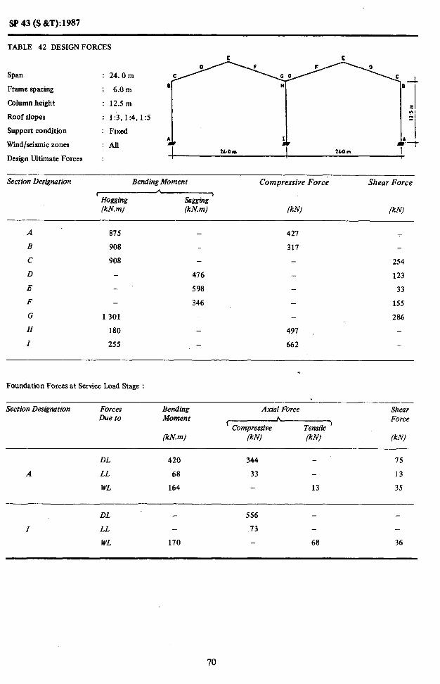
SP 43 (S i&T):1987
TABLE 42 DESIGNFORCES E E
SPan : 24.Om
Frame spacing : 6.0m a
Column height : 12.5 m E
Roof slopes : 1:3, I:!, 15 ;I
Support condition : Fixed I
Wind/seismic zones : All .:-t 21.0 m 2CQm
Design Ultimate Forces : I
Section Designation Bending Moment Compressive Force Shear Force
c c
j Hwging sagging (kN. m) (kn! m) (kW (klv)
A 815 - 421 I
B 908 - 317 -
c 908 - - 254
D 476 - 123
E - 598 - 33
F - 346 155
G 1 301 _ - 286
H 180 - 497 - \
I 255 662
.
Foundation Forces at Service Load Stage :
Section Designation Forces Due to
Bending Moment
(khr. m)
Atil Force Shear
’ Compressive h
Tensile I Force
(kN) (kW (kN)
DL 420 344 - 75
A LL 68 33 - 13
WL 164 - 13 35
DL - 556 -
I LL 73 - -
WL 170 - 68 36
70

SP 43 (S &CT): 1987
TABLE 43 DESIGNFORCES
E E
SPan : 24.0m .-
Frame spacing : 12.0 m q n B
Column height : 9.5 m E :
Roof slopes : 1:3,1:4,1:5 I
Support condition : Fixed .;-
Wind/seismic zones : All 2L.Om I 2b-Om
Design Ultimate Forces :
Section Designation Bending Moment Compressive Force Shear Force
(Hogging (kN. m) (kN.m) (kN) (kN)
A
B
C
D
E
F
G
H
I
1271
1 399
1399
32
-
22
1720
-
52
587
737
474
57
- -
319 -
471 -
475
- 366
174
- 59
- 201
- 393
1005
724
Foundation Forces at Service Load Stage :
Section Designation Forces Due to
Bending Moment
(kN.m)
Axial Force Shear
r * Force
Compressive Tensile 1
(kN) (kN) (kN)
A
DL
LL
WL
650
158
198
381
68
-
-
-
31
144
38
52
DL. - 654 -
I LL - 144
WL 213 134 57
71

-
SP43(S&T):1987 ~ _~ - ~~
TABLE 44 DESIGN FORCES L E 0 F F 0
GG Span
c : 24.0m
c B
It
H i Frame spacing : 12.0m
Column height : 12.5 m E (I) II
Roof slopes : 1:3,1:4,1:5
Support condition : Fixed ..-I
A
Wmd/seismic zones :All ! 24.0 m 2com
Design Ultimate Forces :
Section Designation Bending Moment Compressive Force Shear Force
’ Hogging sasging . (kn! m) (kN.m) (kN) (kN;
1352
1331
1331
26
-
22
1908
359
511
512 -
- 465 -
121 312
698 180
811 - 73
526 - 228
48 419
- 615 -
780 -
.
Foundation Forces at Service Load Stage :
Section Designation
A
Forces Due to
DL
LL
WL
Bending Moment
(kN. m)
574
135
328
Axial Force
rCompressive (kN) FN)
413
66
- 26
Shear Force
(kN)
103
26
71
DL 702 -
I LL - 147 -
WL 340 - 136 73
72
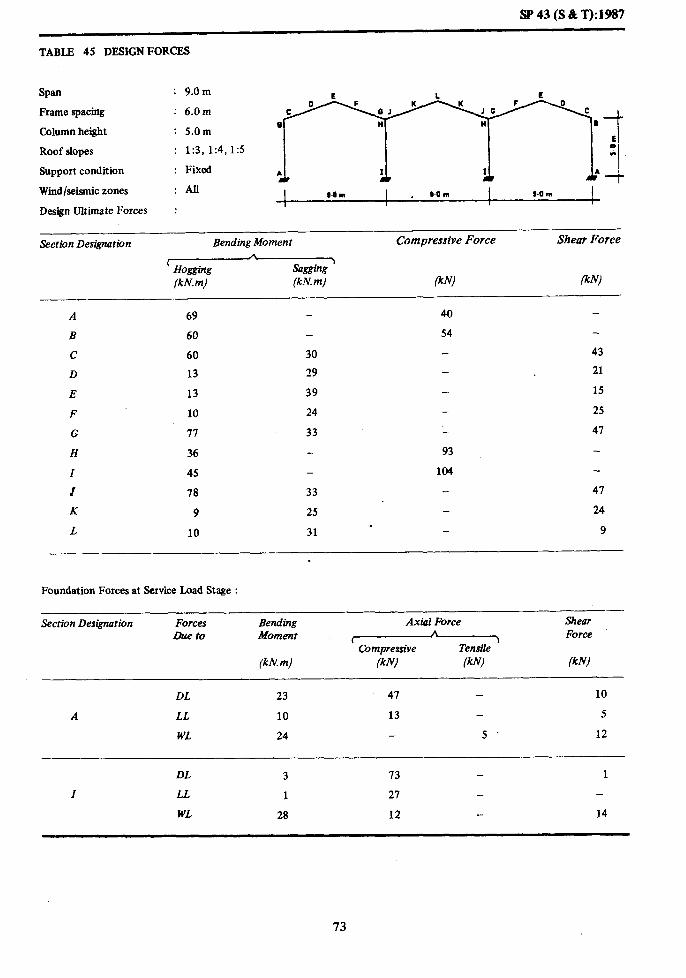
SP 43 (S 8t T):1987
TABLE 45 DESIGN FORCES
Span : 9.0m
Frame spacing
Column height
Roof slopes
Support condition
; ;;!:4,1:5 ;j
Wind/seismic zones :AIl I SOrn . s.0 m I 9.0 m I
Design Ultimate Forces I
:
Section Designation Bending Moment Compressive Force Shear Force A
r Sagging
> Hogging (kN.m) (kN.m) FN) (kN)
A 69 - 40
B 60 54
c 60 30 43
D 13 29 - 21
E 13 39 - IS
F 10 24 - 25
G 17 33 - 41
H 36 93
Z 45 - 104
I 18 33 47
K 9 25 24
L . 10 31 9
- -
Foundation Forces at Service Load Stage :
Section Designation
A
Forces Dueto
DL
LL
WL
Bending Moment
(kn! m)
23
10
24
Axial Force
(Compressive (kN) W)
41
13 -
- 5 .
Shear Force
/kN)
10
5
12
DL 3 13 1
Z LL 1 21
WL 28 12 14
73

SF’43(S&T):1987
TABLE 46 DESIGN FORCES E
Span : 9.0m
Frame spacing : 6.0m
Column height : 6.5 m
Roof slopes : 1:3,1:4,1:5
Support condition : Fixed
Wind/seismic zones : All
Design Ultimate Forces :
Section Des&nation
A
B
c
D
Bending Moment Compressive Force Shear Force t A
Hogging >
Sagging (kN. m) (kN.m) (kN) (kN)
.- ‘\
93 35
66 38 -
66 35 - 49
11 39 - 24
E 10 50 - 18
F 8 31 - 31
G 94 27 - 56
H 51 73 -
I 62 132 -
J 99 21 - 56 K I 32 - 30 . L a 38 12
Foundation Forces at Service Load Stage :
Section Designation
---
Forces Due to
Bending Moment
(kn! m)
Ax&l Force Shear - I A 1 Force
Compressive TensiIe (kN) (kN) fkN)
DL 23 58 a
A LL 9 12 - 3
WL 39 20 17
DL 2 90
I LL 1 27 -
WL 39 12 16
74

SP43(S&T):19t37
TABLE 47 DESIGNFORCES
Span : 9.0m
Frame spacing : 12.Q m
Column height : 5.0m
Roof slopes : 1:3,1:4,1:5
mm&1
*
Support condition : Fixed I I.0 m I PO m 9.0 m I
Wind/seismic zones ,
:All
Design Ultimate Forces :
Section Designation Bending Moment Compressive Force Shear Force
r 1
Hogging Sagging (kn! m) (kN.m)
A 155
B 139
C 139
D 20
E 18
F 16
G 180
H 73
Z 93
J 182
K 14
L 14
-
48
69
91
56
51
-
-
50
56
73
102
126
226
250
-
. -
-
Foundation Forces at Service Load Stage :
Section Designation
A
Forces Due to
DL
LL
WL
Bending Moment
(kN, m)
56
21
47
Axial Force
(Comprersive (kN) (kN)
85
25 -
- 10
Shear Force
(kN)
25
10
24
DL 6 149 2
Z LL 1 53 - . 1
WL 55 24 - 28
7s

SP43(S%T):1987
TABLE 48 DESIGN FORCES
E I. E
Span : 9.0m
Frame spacing : 12.0m
Column height : 6.5m
Roof slopes : 1:3,1:4,1:5
Support condition : Fixed
Wind/seismic zones : All I
Design Ultimate Forces :
-.. Section Des&nation Bending Moment Compressive Force Shear Force
(Hogging (kN. m) (kN. m) (kN! (kN)
A 191 - 62 -
B 137 - 80 -
c 137 68 - 102
D 21 81 - 50
E 19 103 - 37
F 16 64 65
G 193 51 116 H 101 151 -
I 123 .z 259 -
J 204 50 146
K 14 66 . - 61
L 14 79 24
Foundation Forces at Service Load Stage :
Section Designation Forces Due to
Bending Moment
(kN. m)
Aria1 Force Shear A
( ) Force Compressive Tensile
(kN) (kN) (k Nl
DL 48 90. 17
A LL 17 25 - 7
WL 79 - 40 35
DL 3 157 - 1
I LL 1 54 - _
WL 79 24 - 33
76
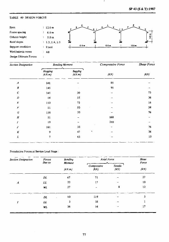
,
SP43 (S&T):1987
TABLE 49 DESIGN FORCES
Span : 12.0m
Frame spacing : 6.0m
Column height : 5.0m
Roof slopes : 1:3,1:4,1:5
BBi
*
Support condition : Fixed I 12-o m I 12-o m I 12.0m I
Wind/seismic zones : AU
Design Ultimate Forces :
Section Designation Bending Moment
x&----- Sagging (kN.m) (kN. m)
Compressive Force Shear Force
(kNl &NJ
A 141
B 145
c 145
D 14
E 110
F 11
G 158
H 51
I 19
J 161
K 9
L I
-
30
55
73
50
33
-
-
33
41
63
85 -
95 -
13
36
16
38
16
168
210 -
-. 76
. 36
10
Foundation Forces at Service Load Stage :
-_____- Section Designation Forces
Due to Bending Moment
(kN. m)
Axial Force Shear ,%
t Compressive Tensile
‘) Force
(kN) (kN1 (kN)
DL 61 71 - 21
A LL 22 17 10
WL 27 - 8 12
DL 10 119 - 3
I LL 3 35 - 1
WL 36 16 17
77

SP43(S&T):1987
TABLE 50 DESIGN FORCES
Span : 12.0m
Frame spacing : 6.0m
Column height : 6.5m
Roof slopes : 1:3,1:4,1:5
Support condition : Fixed
Wind/seismic zones I lZ.OWl : All I 124m I 12Qrn I
I 1 I
Design Ultimate Forces :
Section Designation Bending Moment
v (kN. m) (kN.m)
Compressive Force Shear Force
(kN) (kN)
A 149
B 138
c 138
D 13
E 11
F 11
G 175
H 63
I 82
J 177
K 10
L 8
-
_
34
67
88
54
34
-
-
34
53
71
92
93
-
-
170
201
_.
.- -
-
-
75
37
20
43
81
_
_
81
40
10
Foundation Forces at Service Load Stage :
Section Des&nation Forces Due to
Bending Moment
(kN. m)
Axial Force
z&Gz-Qz (kN) (kN)
Shear Force
(kN)
DL 59 77 - 20
A LL 19 17 - 7
WL 40 - 7 16
-
DL 7 126 - 1
Z LL 2 36 - -
WL 48 16 - 19
78

SP 43 (S & T): 1987
TABLE 51 DESIGN FORCES
Spa : 12.0m
Frame spacing : 6.0m
Column height : 9Sm
Roof slopes : 1:3,1:4,1:5
Support condition : Fixed
Wind/seismic zones :All
Design Ultimate Forces :
Section Designation Bending Moment
w (kN. m) (kN. m)
Compressive Force Shear Force
(kN) fklvl
A 198 - 15
B 141 - 63
C 141 62 15
D 14 84 - 37
E 10 105 25
F 12 65 - 49
G 195 34 .- a7
H 102 113
I 124 - 211
J 208 34 81
K 10 66 41 * L 8 19 - 19
Foundation Forces at Service Load Stage :
Section Designation Forces Due to
Bending Moment
(kN. m)
Axis I Force
r Compressive (kN) (kN)
Shear Force
/kN) -
DL 41 89 - 12
A LL 15 16 1 4
WL 85 26 26
DL 3 142 - -
I LL 1 36
WL 80 16 23
79

SP43(S&T):1987
TABLE 52 DESIGN FORCES
Span : 12.0 In
Frame spacing : 12.0 m
Column height : 5.0m
Roof slopes : 1:3,1:4,1:5
Support condition : Fixed
Wind/seismic zones : All
Design Ultimate Forces :
;f+y-yyj
I 12.0 m I 12.0 m I 12.om I
Section Designation Bending Moment
(Hoaging (kN. m) (kN.m)
Compressive Force Shear Force
(kN) lkN)
A 256
B 262
C 262
D 33
E 28
F 28
G 286
H 100
Z 135
J 291
K 23
L 21
-
17
100
132
90
84
-
85
86
114
127
172
-
-
298
322
- .
-
-
-
133
64
34
68
137
-
-
137
66
18
Foundation Forces at Service Load Stage :
Section Designation Forces Due to
Bending Moment
(kN.m)
Axial Force Shear
I A Force
Compressive Tensile )
fkN) (kN) lkN)
DL 116 107 - 47
A LL 44 35 - 19
WL 55 - 16 25
DL 17 189 - 5
Z LL 5 70 - 1
WL 73 32 - 34
80

St’43 (S&T):1987
T.4BLE 53 DESIGN FORCES
Span : 12.0m
Frame spacing : 12.0m
Column height : 6.5 m
Roof slopes : 1:3,1:4,1:5
Support condition : Fixed
SVind/seismic zones : All I 12.0m I 12,Om I 124m I I I I 1
Design Ultimate Forces :
-___ Section Designation BendingMoment Compressive Force Shear Force
rHogging (kh? m) (kN. m) (kN) ikN)
A 214 - 135 -
B 249 - 168 -
c 249 a4 - 135
D 34 121 _ 67
E 32 158 _ 39
I: 28 99 - 78
G 317 89 - 146
H 126 - 301 -
I 162 - 332 -
J 321 88 - I 146
K 24 98 .4 -. 14
L 24 129 _ 22
Foundation Forces at Service Load Stage :
Section Designation Forces Due to
Bending Moment
(kN.m)
Axial Force
(Compressive
(kN) lkN)
Shear Force
(kN)
DL 103 112 - 34
A LL 38 34 - 14
WL 80 _ 14 31
DL 12 198 _ 2
I LL 3 11 - _
WL 95 32 - 31
81

SP43(S&T):1987
TABLE 54 DESIGN FORCES
E L E
Span : 12.0m E H H
Frame spacing : 12.0m
Column height : 9.5 m .
Roof slopes : 1:3,1:4,1:5 Support condition : Fixed Wind/seismic zones : All Design Ultimate Forces :
Section Designation Bending Moment Compressive Force Shear Force
( A
fht?iw axff~ 1
(kN.m) [kN. m) (kN) ikN)
A 311 - 81 -
B 256 - 108
c 256 138 - 135
D 38 151 - 67
E 32 190 - 51
F 30 120 - 89
G 352 90 - 157
H 206 - 203
I 248 - 351 -
J 380 88 - 157
K 24 124 85
L 25 143 - 37
Foundation Forces at Service Load Stage :
Sect&n Designution Forces Due to
Bending Moment
(kN. m)
Axial Force
‘Compressive A
Tensile ’ (kN) (kN1
Shear Force
(kN)
DL 81 123 - 20
A LL * 29 33 8
WL 171 _ 52 52
DL 4 214 - -
I LL 1 72 - -
WL 161 32 - 47
82

SP 43 (S i&T): 1987
TABLE 55 DESIGN FORCES
Span : 18.0m
Frame spacing : 6.0m
Column height : 6.5m
Roof slopes : 1:3,1:4,1:5
‘Support condition : Fixed
Wind/seismic zones :All
Design Ultimate Forces :
Section Designation Bending Moment
LHogging (kN. m) (kN. m)
Compressive Force Shear Force
(kN1 /kN)
A
B
c
D
E
F
G
H
I
J
K
L
410
436
436
15
-
3
438
110
164
455
4
-
5
1146
191
145
6
-
-
6
126
163
246
191
346
401
- *
-
143
68
29
69
143
143
66
26
Foundation Forces at Service Load Stage :
Section Designation Forces Due to
Bending Moment
(kN.m)
Axial Force shear Force
(kN1 lklvl lkN)
DL 228 158 - 69
A LL 54 26 - 18
WL 51 - 12 17
DL 37 259 - 8
I LL 8 52 - 2
WL 73 24 - 25
83

.
SP 43 (S &T): i 987
TABLE 56 DESIGN FORCES \
Span : 18.0m
llrame spacing : 6.0m
Column height : 9.5m
Roof slopes : 1:3,1:4, 1:5
Support condition : Fixed I II.0 m I 18.0 m I 180 m I I 1 I
Wind/seismic zones : All _
Design Ultimate Forces :
Section Designation Bending Momerzt
FsogginR (kM. m) (kN.m)
Compressive Force Shear Force
(kN) (kN)
A
B
c
D
E
F
G
H
I
J
K
L
422
413
413
6
-
2
516
143
193
519
3
-
-
13
194
256
157
2
_
L
148
208
219 -
185
- 148
73
- 27
84
- 159
350 -
430 -
159 * - 79
- 15
Foundation Forces at Seticw Load Stage
Section Designation
A
Forces Due to
DL
LL
WL
Bending Moment
(kN. m)
195
43
87
Axial Force
(Compressive WV /W
179 -
25 -
- - 11
Shear Force
iklvl
44
11
23
DL 24 289 3
I LL 3 53 -
WL 104 24 28

SP43(S&T):1987
TABLE - 57 DESIGN FORCES
Span : 18.0m
Frame spacing : 6.0m
Column height : 12.5 m
Roof slopes : 1:3,1:4, I:5
Support condition : Fixed
Wind/seismic zones : All I 10.0 * I l&O m I 1.0 m I I I I
Design Ultimate Forces :
Section Designation Bending Moment Compressive Force Shear Force b
f -I Hogging sagging (kN. m) (kN.m) lkN) (kN)
A
B
c
D
E
F
G
H
I
J
K
L
2
561
190
243
571
3
- 195
- 139
57 -
231 -
295 _
174 -
- -
- 227
459
- -
168 *
228 -
-
148
74
34
93
168
-
_
168
87
23
Foundation Forces at Service Load Stage :
Section Designation Forces Due to
Bending Moment
(kNm)
Axial Force
1 Compressive lkN) /kN)
~__._. Shear Force
fkN)
DL 165 201 30
A LL 36 25 7
WL 143 41 33
DL 13 312 -_ 1 I LL 1 54 -
WL 149 24 - 32
85

, ._.
SF’43 (S &T):1987
TABLE 58 DESIGN FORCES
Span : 18.0m
Frame spacing : 12.0m
Column height : 6.5m
Roof slopes : 1:3,1:4,1:5
Support condition
Wmd/seianic zones
: Fixed
:AU
Design Ultimate Forces :
Section Designation Bending Moment
(Hogging (kN. m) (kN.m)
Compressive Force
(kN)
Shear Force
ikN)
A 669
B 103
C 703
D 51
E 26
F 40
G 706
H 209
I 301
J 733
K 34
L 18
-
111
235
3.08
234
115
-
117
201
261
258 -
307 -
- 231
- 110
- 48
- 110
- 231
540 -
595 -
- 231
109
- 41
Foundation Forces at Service Load Stage :
Section Designation Forces Due to
Bending Moment
(kN.m)
Axial Force Shear A
L I Force Compressive Tensile
(kN) (kN) fkN)
DL 344 212 - 104
A LL 108 52 - 35
WL 103 - 25 33
DL 56 365 - 12
I LL 15 105 - 3
WL 145 47 - 51
86
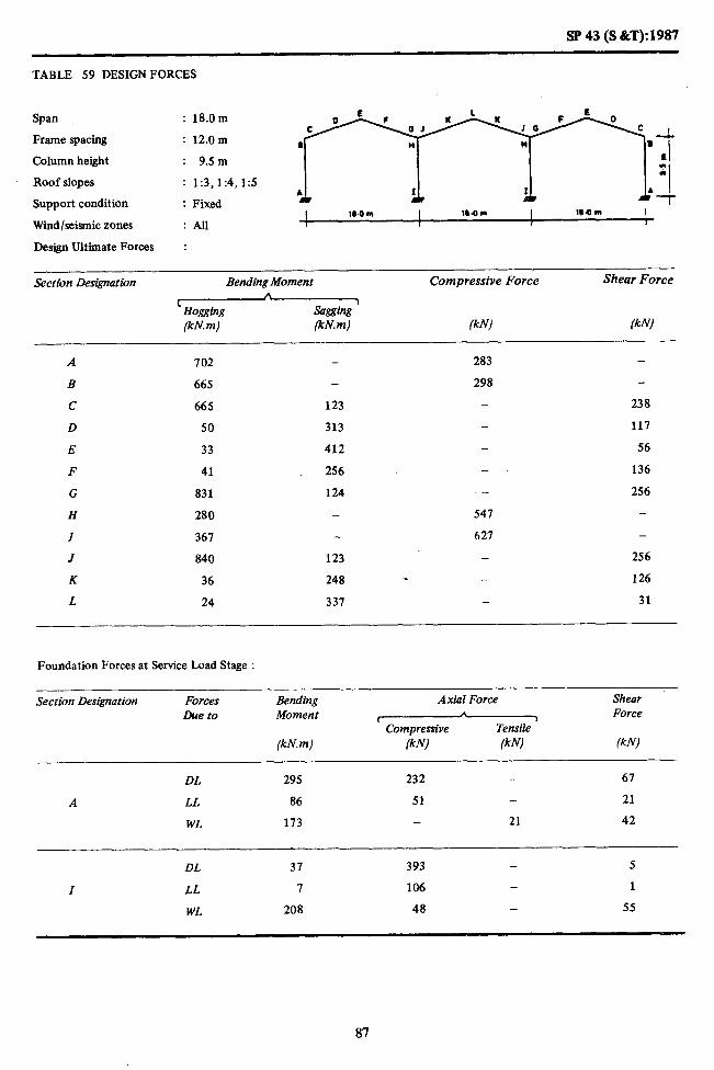
SP 43 (S &T):1987
TABLE 59 DESIGN FORCES
Span : 18.0m
Frame spacing : 12.0m
Column height : 9.5 m
Roof slopes : 1:3,1:4,1:5
Support condition : Fixed I l#.Orn I 18.Orn I IBQ m I
Wind/seismic zones : All / r 1
Design Ultimate Forces :
-- Section Designation Bending Moment Compressive Force Shear Force
A ‘Hogging
j sagging
(kN. m) FN.ml (kN) (kNl
A 102 283 - -
B 665 298
C 665 123 - 238
D 50 313 - 117
E 33 412 - 56
F 41 256 - 136
G 831 124 - 256 H 280 547 -
I 361 621 -
J 840 123 - 256
K 36 248 . .- 126
L 24 331 - 31
Foundation Forces at Service Load Stage :
Section Designation
A
I
Forces Due to
DL
LL
WL
DL
LL
WL
Bending Moment
(kN.m)
295
86
173
37
I
208
Axial Force
r Compressive FNJ (kN)
232 -
51 -
- 21
393 -
106 -
48 -
Shear Force
(kN)
61
21
42
5
1
55
87

SP43(S&T):1987 - .I
TABLE 60 DESIGNFORCES
Span : 18.0m
Frame spacing : 12.0m
Column height : 12.5 m
Roof slopes : 1:3,1:4,1:5
Support condition ’ Fixed
Wind/seismic zones :AlI I 104m I ll.Om 1 180" I
Design Ultimate Forces :
Section Designation Bending Moment Compressive Force Shear Force
(kN. m) Wm) IkW lkNj
A 803 - 212 _
B 633 - 204 -
c 633 203 - 239
D 46 312 - 119
E 31 476 - , 68
F 40 288 150
G 904 122 - 271
H 381 - 361 _
I 476 658 -
J 932 121 - 271
K 36 286 _ * 141
L 24 361 - 46
Foundation Forces at Service Load Stage :
Section Des&nation Forces Due to
Bending Moment
Wm)
Axial Force
I Compressive
(klv! (kN)
Shear Force
(kNj
DL 250 252 - 46
A LL 12 50 - 14
WL 286 - 81 66
DL 20 420 - ‘1
I LL 2 108 _
WL 298 48 - 64
88

SP 43 (S i&T): 1987
TABLE 61 DESIGN FORCES
Span : 9.0m
Frame spacing : 6.0m
Column height : 5.0m
Roof slopes : 1:3.1:4. I:5
Support condition : Fixed
Wind/seismic zones :All
Design Ultimate Forces :
- Section Designation Bending Moment Compressive Force Shear Force
(Hogging (kN. m) (kN. m) (kN) (kNJ
A 72 - 41 - B 62 - 54 - C 62 28 44 D 12 28 22 E 13 38 15 F 11 25 24 G 14 32 46 H 38 - 93 I 49 - 104 J II 33 46 K 8 23 23 L 10 30 8 M 10 23 23 N 75 30 43 0 22 98 P 30 61 -
Foundation Forces at Service Load Stage :
Section Designation Forces Due to
Bending Moment
(kN m)
Axial Force
I Compressive (kN1. (kN)
Shear Force
(kN)
DL 25 41 - 11 A LL 12 13 - 5
WL 23 - 5 11
DL 6 73 - 2 I LL 2 21 1
WL 26 12 - 13
DL - 71 - P LL - 26 - -
WL 20 - 16 10
89
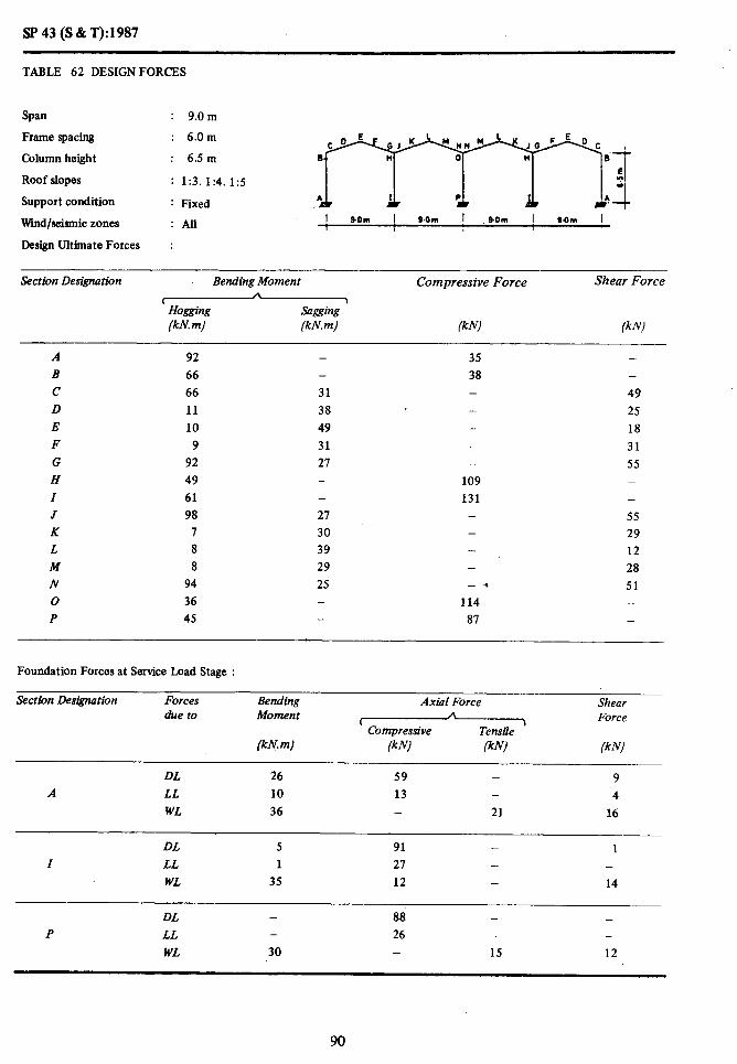
SP43(S&T):1987
TABLE 62 DESIGNFORCES
Spa : 9.0m
Frame pacing : .
Column height
Roof slopes
: x ;;I
: 1:3.1:4.1:5
Support condition : Fixed
Wmd/seismic zones :All I 0th I SOm I .0_0m I S.Om I I 1 I
Design Ultimate Forces :
Section Designation Bending Moment Compressive Force Shear Force
r Hogging (kN.m)
Sagging ’ (kN. m) PV
A 92 - 35 -
B 66 - 38 -
c 66 31 - 49
D 11 38 25
E 10 49 - 18 F 9 31 - 31
G 92 21 - 55 H 49 - 109 _
I 61 - 131 _
J 98 27 - 55
K I 30 - 29
L 8 39 12
M 8 29 28
N 94 25 -, 51 0 36 _ 114 -
P 45 87 -
Foundation Forces at Service Load Stage :
Section Designation
A
Forces due to
DL LL
WL
Bending Moment
(kN. m)
26 10
36
Axial Force Shear A
t \ Force Compressive Tensile
IkN) (kN) (kN)
59 - 9 13 - 4
21 16
DL 5 91 - 1 I LL 1 21 - _
WL 35 12 14 -
DL - 88 - -
P LL - 26 - -
WL 30 - 15 12
90

SP 43 (S &T): 1987
TABLE 63 DESIGNFORCES
Span : 9.0 m
Frame spacing
Column height
Roof slopes
Support condition
Wind/seismic zones
: 12.0m
: 5.0m
: 1:3.1:4.1:5
: Fixed
:All
;I$
1 9.h I 9.on I 9.0m I 00m I
Design Ultimate Forces :
Section Designation Bending Moment Compressive Force Shear Force
I
Hogging (kN.m)
sagging ’ (kN. m) (W ;kN)
A 162 103 -
B 144 - 127 c 144 43 102 D 19 66 - 51 E 18 89 30 F 16 58 - 51 G 173 49 - 108 H 18 225 - Z 101 249 -
J 181 51 - 108
K 13 52 - 55
L 14 71 - 16 M 15 52 - 52
46 u N 173 - 102 0 - 251 - -
P 59 - 162 -
Foundation Forces at Service Load Stage :
Section Designation Forces Due to
Bending Moment
(kh! m)
Axial Force Shear
t A Force Compressive Tensile ’
(kN) (kN) (kN)
DL 62 85 - 26 A LL 23 26 - 10
WL 46 - 10 22
DL 15 149 - 5 I LL 4 53 - 1
WL 53 23 - 26
DL - 146 - -
P LL - 52 - -
WL 39 - 31 20
91

SP 43 (S & T): 1987
TABLE 64 DESIGNFORCES
Span : 9.0m
Frame spacing : 12.0 m
Column height : 6Sm
Roof slopes : 1:3.1:4.1:5
Support condition : Fixed 1 cam I s.om I .+Om 1 COm I
Wind/seismic zones I 1 I
: All
Design Ultimate Forces :
Section Designation Bending Moment Compressive Force Shear Force b
( 1 Hogging sagging (kN. m) IkNm) FN) (kN)
A 189
B 137
c 187
D 20
E 18
F 16
G 189
H 98
I 122
J 197
K 13
L 14
M 15
N 194
0 71
P 91
-
59
78
101
64
50 -
-
51
61
80
60
47
62 80 - - - - -
227 258
- - .
236 170
-
102
51
35
63
115 -
-
115
60
24
58
106 -
Foundation Forces at Service Load Stage :
Section Designation Forces Due to
Bending Moment
(kN. m)
Axial Force Shear A b Force
t Compressive Tensile (kN) (kN) (kN)
DL 53 91 - 18
A LL 19 25 - 7 WL 73 _ 41 31
DL 10 158 - 2
I LL 2 54 1
WL 71 23 - 28
DL - 154 - _
P LL 51 - -
WL 60 _ 31 25
92

SP 43 (S &T): 1987
TABLE 65 DESIGN FORCES
Span : 12.0 m
Frame spacing : 6.0m
Column height : 5.0m
Roof slopes : 1:3.1:4.1:5
Support condition : Fixed
kind/seismic zones :All I 12 Om I 12 Om 12.Om I
Design Ultimate Forces :
Section Des&nation Bending Moment Compressive Force Shear Force
(Hogging (kN. m) (kN.m) (ki; (kN)
A B C D E F G H Z J K L M N 0 P
153
151 151
16
9
11
149
60
38
164
9
6
10
149 -
31
51
71
52
31 -
-
34
42
52
46
30 -
87 -
96 - 74 - 36 - 17
_ 36 - 74
167 211 -
_ 74 _ 36 - 14 - 34
* - 70 189 -
213 -
Foundation Forces at Service Load Stage :
Section Designation Forces Due to
Bending Moment
(kN, m)
Axial Force Shear
( A
1 Force Compressive Tensile
(kN) (kN) (kN)
DL 73 72 - 29 A LL 25 18 - 10
WL 29 8 12
DL 19 119 - 6 Z LL 6 35 - 2
WL 38 16 - 17
DL 117 - -
P LL 34 - -
WL 23 - 21 11
93

I
SP 43 (S & T): 1987
TABLE 66 DESIGNFORCES
Span : 12.0m
Frame spacing : 6.0m
Column height : 6.5m
Roof slopes : 1:3.1:4.1:5
Support condition : Fixed
Wind/seismic zones : All
Design Ultimate Forces :
lZ.Ofll I V&OR? I 1ZOm I 1ZOm I I I
Section Designation Bending Moment
IHogging (kN.m) (kN. m)
Compressive Force
(kN)
Shear Force
(kN)
A 157 93 - - B 144 - - 94
C 144 30 - 75 D 13 63 - 31 E 10 85 20 F 11 56 - 41 G 168 33 - 79 H 70 169 - - I 93 - _ 200
J 177 35 - 79 K 9 49 - 40 L 8 68 - 10 M 10 51 - 38 N 167 32
. . - 75
0 37 - 175 - p. 50 - 142 -
Foundation Forces at Service Load Stage :
Section Designation Forces Due to
Bending Moment
(kN. m)
Axial Force
(compressive (kN1 (kN)
Shear Force
(kNj
DL 66 78 - 21 A LL 21 17’ - I
WL 39 - 7 15 _.
DL 16 127 - 4 I LL 4 36 - 1
WL 46 15 - 17
DL - 124 - -
P LL - 34 - -
WL 34 - 21 13
94

SP 43 (S & T): 1987
TABLE 67 DESIGNFORCES
Span : 12.0 m Frame spacing
Column height
Roof slopes
Support condition
Wind/seismic zones
;_: : 1:3. 1:4.1:5
: Fixed
;;I]
I lZ.OWl I 12.Olll 1lOrn I 12.0m I 1 I Design Ultimate Forces :
Section Des&nation
A
B C D E F G H
Z
J K L M N
0 P
Bending Uomen t Compressive Force Shear Force
m (kN. m) (kN.mJ (kN1 (kN)
194 - 75 -
139 - 63 139 53 - 75
12 81 - 37 10 103 - 25
11 65 - 48
191 33 - 86 98 - 172 -
120 217 -
206 34 - 86 9 62 - 46 8 81 _ 19
10 62 - 44 196 32 * - 79
76 176 94 - 157 -
Foundation Forces at Service Load Stage :
Section Designation
A
Forces Duet0 I
DL LL WL
Bending Moment
(kN.m)
52 16 78
Axial Force Shear A
( Force Compressive Tensile ’
(kN) (kN) (kN)
89 - 12 17 - 4 - 27 23
DL 9 142 - 1 Z LL 2 36
WL 71 15 - 20
DL - 137 - P LL - 34 -
WL 63 - 20 18
95
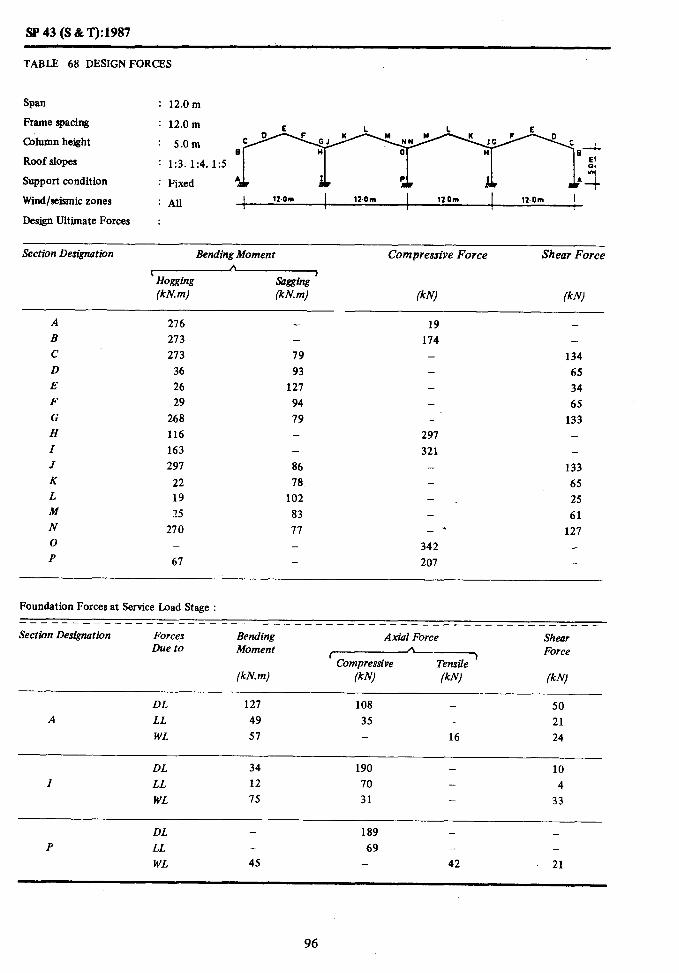
SP43(S&T):1987
TABLE 68 DESIGN FORCES
Span : 12.0m
Frame spacing : 12.0 m E I. L E Column height : 5.0m
B Roof slopes : 1:3.1:4.1:5 : Support condition : Fixed I P b *J 4
Wind/seismic zones : All I lZ.Orn I lI.Om 12.Om 1 12.Om I I I
Design Ultimate Forces :
Section Designation Bending Moment Compressive Force Shear Force
(kN. m) (kn! m)
A 216 B 273 -
c 273 79
D 36 93 E 26 127
F 29 94
G 268 19 H 116 -
Z 163 -
J 297 86 K 22 1%
L 19 102 M 25 83 N 270 77 0 - - P 61 -
- - - - -
291 321 - -
- - *
342 207
134 65 34 65
133
133 65 25 61
127
Foundation Forces at Service Load Stage : -------------------------_------------___ ---_---------- Section Des&nation Forces Axial Force
Due t0 Bending Shear Moment
e Tensile ’ Force
(kN. m) (kN1 (kN) (kN’l
DL 127 108 - 50 A LL 49 35 - 21
WL 51 - 16 24
DL 34 190 - 10 Z LL 12 70 - 4
WL 75 31 - 33
DL - 189 - -
P LL - 69 - -
WL 45 - 42 21
96

SP 43 (S &T): 1987
TABLE 69 DESIGNFORCES
Span : 12.0m
Frame spacing : 12.0m
Column height : 6.5m
Roof slopes : 1:3,1:4,1:5\
Support condition : Fixed
Wind/seismic zones :AII
Design Ultimate Forces :
Section Designation Bending Moment
lHogging (kN. m) (kN. m)
Compressive Force Shear Force
(kN) (kN)
A
B
c
.D E
F
G
H
Z
J
K
L
M
N
0
P
289
259
259
34
31
29
303
137
119
320
23
24
26
304
74 101
-
-
76
114
154
97
86
90
91
123
92
82
- -
136
170
-
-
300
331
-
-
* -
313
215
-
-
136
68
39
75
143
-
-
143
73
21
69
135
_
-
Foundation Foices at Service Load Stage :
Section Designation Forces Due to
Bending Moment
(kN. m)
Axial Force
(compressive (kN) (kN)
Shear Force
(k N)
DL 114 113 37
A LL 42 34 14
WL 79 - 14 29
DL 28 198 I
Z LL 8 71 - 2
WL 92 31 - 34
DL - 194 - _
P LL - 69 -
WL 67 - 41 26
97

SP 43 (S & T): 1987
TABLE 70 DESIGNFORCES
Span
Frame spacing
Column height
Roof slopes
Wind/seismic zones
;_t ;I;]
:AB ll.OUl I 120m 120m I 110m I / I I Design Ultimate Fdrces. :
Support condition
Sect&m Designation Bending Moment Compressive Force Shear Force
I Hogging s7ggihg ’ (kN. m) (kN. m) /kN) (kN)
A 368
B 252
c 252 D 34 E 32 F 28
G 346 H 194
Z 237
J 375
K 24
L 25
M 26
N 359
0 151
P 188
-
120
147
187
119
89 - -
90
115
146
114
83 -
86
106 - - - -
304
349
315
231
-
136
68
50
87
155 -
155
83
36
80
142
Foundation Forces at Service Load Stage :
Section Designation Forces Bending Due to Mbment
Axial Force
rCompreJaive_
Shear Force
(kN.m) /kN) IkN) (kN)
DL 89 124 - 21 A LL 32 33 - 8
WL 156 - 54 47
DL 16 215 - 2 Z LL 3 73 - 1
WL 142 31 40
DL 207 - - P LL - 69 - -
WL 126 - 41 36
98

SP43(S&T):1987
TABLE 71 DESIGN FORCES
Span : 9.0 m
Frame spacing : 6.0m
Column height : 5.0 m
Roof slopes : 1:3,1:4,1:5
Support condition : Hinged
Wind/seismic zones :All
Design Ultimate Forces :
Section Designation Bending Moment Compressive Force Shear Force
’ Hogging (kN. m)
s11&ping ’ (kN. m) (kN) (kN)
A 124 -
B 126 77 -
c 126 65 81
D 19 86 44
E - 114 - 22
Foundation Forces at Service Load Stage :
Section Designation Forces Due to
Bending Moment
(kN.m)
Axial Force
z&EzfTz (kN) (kN)
Shear Force
(kN)
DL - 82 - 9
A LL - 13 2
WL - - 1 17
99
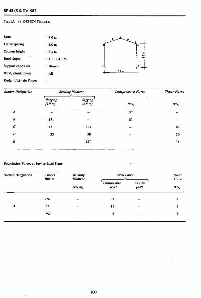
W43(S&T):1987
TABLE 72 DESIGNFORCES
Span : 9.0m
Frame spacing : 6.0m
Column height : 6.5 m
Roof slopes : 1:3,1:4,1:5
Support condition : Hinged
Wind/seismic zones I 90m I
:All I
Design Ultimate Forces :
Section Designation
A
B
C
D
E
Bending Moment
(Hogging (kN. m) (klv m)
-
171 -
171 113
33 99
- 127
Compressive Force
(kN
132
87
-
-
Shear Force
(kW
-
-
a2
50
34
Foundation Forces at Service Load Stage : .a
Section Desigwtion Forces Due to
Bending Moment
(kN. m)
Axial Force
[Comprrnive
/kN) lkN
Shear Force
(kN’l
DL - 91 - 7
A LL - 13 - 2
WL - 6 - 3
100
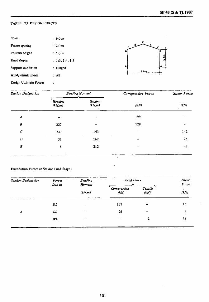
SP 43 (S &T):1987
TABLE 73 DESIGNFORCES
Span : 9.0 m E
Frame spacing : 12.0 m
Column height : 5.0m 8
Roof slopes : 1:3,1:4,1:5
Support condition : Hinged •.
Wind/seismic zones : AB
Design Ultimate Forces :
Section Designation Bending Moment Compressive Force Shear Force
C A 1
Ho&$% sagging (kN. m) W.m) (klvl (klv/
A - 199 -
B 227 - 128 -
C 227 143 - 142
D 51 162 76
E 5 212 - 44
. Foundation Forces at Service Load Stage :
Section Designation Forces Due to
Bending Moment
(kN m)
Axial Force Shear b
t Force Cbmpressive Tensile ’
(kY (kW iW
DL - 123 15
A LL _ 26 4
WL - - 2 34
101
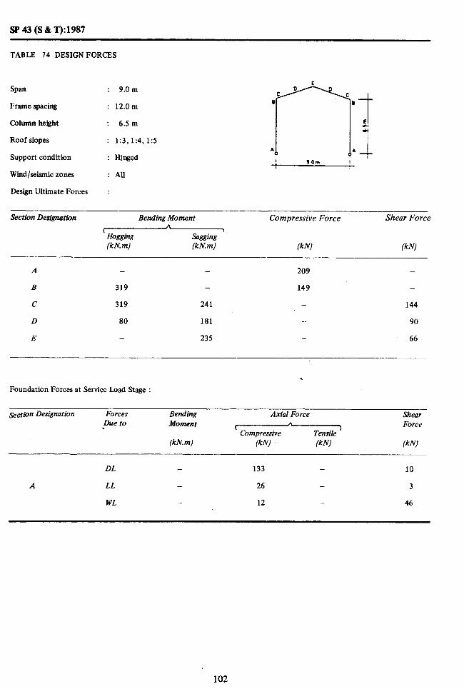
SP 43 (S & T): 1987
TABLE 74 DESIGNFORCES
E
Span : 9.0 m
Frame spacing : 12.0m
Column height : 6Sm
Roof slopes : 1:3,1:4,1x5
Support condition : Hinged
Wind/seismic zones : All
Design Ultimate Forces :
Section De&nation Bending Moment
lHogging (kh! m) (kN. m)
Compressive Force Shear Force
lkW fklvl
A - - 209 -
B 319 - 149 -
c 319 241 144
D 80 181 - 90
E - 235 _ 66
Foundation Forces at Service Load Stage :
Section Designarion Forces Due to
Bending Moment
(kN m)
Axial Force
%G&z?7a
IkW (W
Shear Force
W”)
DL - 133 - 10
A LL - 26 - 3
WL - 12 46
102
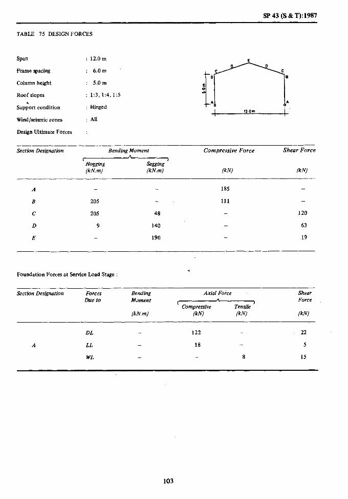
SP43(S&T):1987
TABLE 75 DESIGN FORCES
SDUl : 12.0 m c
Frame spacing : 6.0m
Column height
Roof slopes
Suppbrt condition
Wind/seismic zones
Design Ultimate Forces
: 5.0m
: 1:3, 1:4,1:5
: Hinged
: All
:
4.4 I 12.0m
Section Designation Bending Moment Compressive Force Shear Force
I
Hogging Sagging ’ (kN. m) (kN. m) (kN) FN)
A - 185 -
n 205 111 -
c 205 48 120
D 9 140 63
E 190 19
x Foundation Forces at Service Load Stage :
Section Designation Forces Due to
Bending Moment
(kN.m)
Axial Force Shear A
( ) Force Compressive Tensile
(kN) (kN) (kN)
DL - 122 - 22
A LL 18 - 5
WL - 8 15
103

SP 43 (S & T): 1987
TABLE 76 DESIGN FORCES
Span : 12.0m E
Frame spacing : 6.0m B
Column height : 6Sm
Roof slopes : 1:3,1:4,1:5
Support condition : Hinged A
Wind/seismic zones : All
Design Ultimate Forces :
Section Designation Bending Moment
IHoggil2g (kN. m) (kN. m)
Compressive Force Shear Force
(kN) (kN)
A _ - 19.7 -
B 247 - 119 -
C 247 95 - 122
D 22 160 - 66
E - 216 - 29
. Foundation Forces at Service Load Stage :
Section Des&nation Forces Due to
Bending Moment
(kN.m)
Axial Force
Tmrile Compressive (kN) (kN)
Shear Force
(kN)
DL 135 16
A LL 18 3
WL - 2 21
104

sP43(S&T):1987
TABLE 77 DESIGNFORCES
Span : 12.0m
Frame spacing : 6.0m
Column height : 9.5m
Roof slopes : 1:3,1:4,1:5
Suppoit condition : Hinged
Wind/seismic zones : AU
Design Ultimate Forces : 1 12.Om 1
Section Designation Bending Moment Compressive Force Shear Force
f * Hogging Sagging
7
(kN. RI) (kN. m) (k N) (kN) - --
A - - 252 -
B 388 - 164 -
C 388 218 144
D 38 248 - 91
E - 307 - 55
Foundation Forces at Service Load Stage :
Section Designation Forces Due to
Bending Moment
(kN.m)
Axial Force Shear n
t 1 Force Compressive Tensile
(kN) (kN) (kN)
DL - 186 11
A LL - 18 - 2
WL - 12 40
105

SP43(S&T):1987
TABLE 78 DESIGNFORCES
Span : 12.0 m E 0 0
Frame spacing : 12.0 m
t
C C
e e
Column height : 5.0m
Roof slopes !I
: 1:3,1:4,1:5 .* A
Support condition : Hinged c I___! 12.Om
Wind/seismic zones : All
Design Ultimate Forces :
Section Designation Bending Moment Compressive Force Shear Force
Hogging (kN. m)
Sagging ’ (kN. m) fkN) fkN)
A - - 290 -
B 340 - 176
c 340 133 203
D 41 254 - 108
E - 341 - 39
. Foundation Forces at Service Load Stage :
Section Designation Forces Due to
Bending Moment
(kN. m)
Axial Force
I Compressive
(kN) (kN)
Shea7 Force
(kN)
DL 179 - 34
A LL 35 9
WL - 15 30
106

!P43(S&T):1987
TABLE 79 DESIGN FORCES
Span : 12.0m
Frame spacing : 12.0m
Column height : 6.5m
Roof slopes : 1:3,1:4,1:5
Support condition : Hiqqd
Wind/seismic zones : All
Design Ultimate Forces :
Section Designation Bending Moment Compressive Force Shear Force h
c 7 Hogging &gging (kN. m) FN.m) WV WV
A - - 303
B 426 192 - -
c 426 226 207 j
D 71 291 - 111
E 386 57
Foundation Forces at Service Load Stage :
Section Designation Forces Due to
Bending Moment
(kN.m)
Axial Force Shur A
t 1 Force Compressive TefWile
(kN) (kN) (kN)
DL - 194 - 25
A LL - 35 6
WL - - 4 43
107
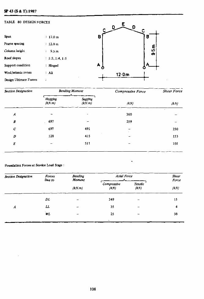
SP 43 (S & T):1987
TABLE 80 DESIGNFORCES
ban : 12.0m E
Frame spacing : 12.0 m
Column height : 9.5m
Roof slopes : 1:3,1:4,1:5
Support condition : Hinged A
Wiid/seismic zones : All
Design Ultimate Forces :
Section Designution
A
B
C
D
E
Bending Moment
(Hogging Wml (kn! m)
691
697 491
128 415
- 511
Compressive Force
(kN)
360
259
-
-
Shear Force
(kNJ
230
153
105
. Foundation Forces at Service Load Stage :
Section Designation Forces Due to
Bending Moment
(kN.m)
Axial Force
v (kNl (kN)
Shear Force
WJ --
DL 249 - 15
A LL 35 - 4
‘WL 25 - 38
108

SP43(S&T):1987
TABLE 81 DESIGN FORCES
Span : 18.0m
Frame spacing : 6.0m
Column height : 6.5 m
Roof slopes : 1:3,1:4,1:5
Support condition : Hinged
Wind/seismic zones : All
Design Ultimate Forces :
18.Om 1
Section Designation Bending Moment Compressive Force Shear Force
lHogging I (kN. m) (kN. m) (kN) (kN)
A - - 289
B 480 234
c 480 51 192
D - 324 100
E 439 23
Foundation Forces at Service Load Stage : ,
Section Designation Forces Due to
Bending Moment
(kN. m)
Axial Force Shear A
’ Compressive -I Force
Tensile (kN) (kN) (kNJ
DL - 191 - 41
A LL - 26 - 8
WL - - 14 17
109

SP 43 (S & T):1987
TABLE 82 DESIGNFORCES
: 18.0m
Frame spacing
Column height
Roof slopes
Support condition
Wind/seismic zones
: 6.0m
: 9.5 m
: 1:3, 1:4,1:5
: Hinged
: All
Design Ultimate Forces : 1 18-O m 1
Section Designation Bending Moment
(Hogging (kn! m) (kN. m)
Compressive Force Shear Force
(kW (kN
A - - 335 -
B 593 - 212 -
C 593 168 211
D 5 440 - 113
E 586 - 44
Foundation Forces at Service Load Stage :
Section Designation Forces Due to
Bending Moment
(kN. m)
Axial Force Shear
t I\ Force
Compressive Tensile )
(kNl (kW - (klv)
DL - 234 28
A LL _ 26 5
WL - 4 31
110

SP 43 (S & T): 1987
TABLE 83 DESIGN FORCES
Span : 18.0m
Frame spacing
Column height
Roof slopes
Support condition
: 6.Om
: 12.5m
: 1:3,1:4,1:5
: Hinged A
wind/seismic zones
Design Ultimate Forces
: All
: 1 18-O m 1
Section Designation Bending Moment
(Hogging (kN.m) (kN. m)
Compressive Force
(k N)
Shear Force
(kJJ)
A - 401
B 193 - 226
c 793 334 - 243
D 2 594 - 138
E - 171 - 69 *
Foundation Forces at Service Load Stage :
Section Des.@ation Forces Due to
Bending Moment
(kN m)
Axial Force Shear h
( Tensile
j Force
Compressive
(kN) (kN) (kN)
DL - 301 - 21
A LL - 26 - 3
WL - 9 _ 44
111
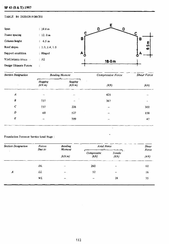
SP 43 (S & T): 1987
TABLE 84 DESIGN FORCES
Span : 18.0m
Frame spacing : 12.Om
Column height : 6.5 m
Roof slopes : 1:3,1:4,1:5
Support condition : Hinged
Wind/seismic zones
Design Ultimate Forces
: All
: 1 18-O m 1
Section Designation Bending Moment Compressive Force Shear Force
r n 1 Hw@g sagging (kN.m) (kN.m) (kN) (kW
A - 425 _
B 131 - 367 -
c 131 226 - 302
D 68 521 - 158
E - 709 _ 47
. Foundation Forces at Service Load Stage :
Section Designation Forces Due to
Bending Moment
(kN m)
Axin Force Shear 1. , 1 Force
Compressive Tensile
(kN) /kN) (kNJ
DL _ 260 - 60
A LL - 52 - 16
WL - - 28 35
112

SP43(S&T):1987
TABLE 85 DE~IGNGORCES
: 18.0m
Frame spacing : 12.0m
Column height : 9.5 m
Roof slopes : 1:3,1:4,1:5
Support condition
Wind/seismic zones
: Hinged
: All.
i
I
Design Ultimate Forces : 1 18-O m 1
Section Designation Bending Moment Compressive Force Shear Force
( Hoi&w (kN.mj
A I
Sagging (kh! m) (kN) fkN)
A - 493 -
B 918 - 319 -
c 978 451 - 339
D 111 745 - 182
E 981 - 84
Foundation Forces at Service Load Stage :
Section Designation Forces Due to
Bending Moment
(kN.m)
Axial Force
lCompressive
(kN) (k N)
Shear Force
(kN)
DL _ 322 _ 40
A LL _ 52 _ 10
WL - _ 9 63
113

SP43(S&T):1987
TABLE 86 DESIGN FORCES
Span : 18.0m
Frame spacing : 12.0 m
Column height : 12.5 m
Roof slopes : 1:3,1:4,1:5
Support condition : Hinged
Wind/seismic zones : All
Design Ultimate Forces : 1 18.0 m 1 1 -7
Section Designation Bending Moment
w (kN.m) (kN. m)
Compressive Force
(k Nl
Shear Force
(kN)
A - - 589 -
B 1370 - 411 -
c 1370 797 - 387
D 135 1009 - 224
E - 1296 7 132
Foundation Forces at Service Load Stage :
Section Designation Forces Due to
Bending Moment
(kN m)
Axial Force
I Compressive
(kN) (k Nl
Shear Force
(kNJ
DL _ 312 _ 30
A LL _ 52 - 6
WL __ 18 - 89
114

SP43(S&T):1987
TABLE 87 DESIGN FORCES
Span : 24.0 m
Frame spacing
Column height
Roof slopes
Support condition
Wind/seismic zones
: 6.0m
: 9.5 m
: 1:3,1’4, 1:s
: Hinged A
: All
Design Ultimate Forces : 24.Om I *
Section Designation Bending Moment Compressive Force Shear Force
I I
Hogging Sagging (kN m) (kN.m) (kN) ikN)
A - - 522 _
B 1 095 - 339 _
C 1095 _ - 334
D - 791 - 176
E - 1069 _ 37
Foundation Forces at Service Load Stage :
Section Designation Forces Due to
Bending Moment
(kN. m)
Axial Force
V Compressive
fkN) lk N)
Shear Force
(kN)
DL _ 365 _ 67
A LL - 35 _ 10
WL _ - 17 27
115

SP43 (S&T):1987
TABLE 88 DESIGN FORCES
Span
Frame spacing
Column height
Roof slopes
Support condition
Wind/seismic zones
Design Ultimate Forces
: 24.0 m
: 6.0m
: 12.5 m
: 1:3,1:4,1:5
: Hinged
: All
! 21.Om ! Section Des&nation Bending Moment
rHogging (kN. m) (kN.m)
Compressive Force Shear Force
(klvl (kN)
A - - 593 -
B 1288 - 381 -
c 1288 146 - 363
D - 1002 195
E - 1335 - 60 *
Foundation Forces at Service Load Stage :
Section Designation Forces Due to
Bending Moment
(kN. m)
Axial Force
I Compressive
(kN1 (kN)
Shear Force
(klvl
DL - 429 - 51
A LL - 35 - I
WL - - 6 42
116

SP 43 (S & T): 1987
Span : 24.Om B
Frame spacing : 12.0m
Column height : 9.5 m
Roof slopes : 1:3,1:4,1:5
Support condition : Hinged A
Wind/seismic zones : All
TABLE 89 DESIGN FORCES E
Design Ultimate Forces : 24.Om
Section Designation Bending Moment Compressive Force Shear Force
I
Hogging (kN. m)
)
Sagging (kN. m) (klvl
A - _ 708 -
B 1571 - 448 -
C 1571 329 _ 485
D 32 1181 - 256
E _ 1588 _ 73
Foundation Forces at Service Load Stage :
Section Designation Forces Due to
Bending Moment
(kN m)
Axial Force
(Compressive
(klvl @NJ
Shear Force
WI
DL - 460 _ 90
A LL _ 70 - 19 <.
WL - - 33 54
117

SP 43 (S & T): 1987
TABLE 90 DESIGN FORCES
Span
Frame spacing
Column height
Roof slopes
Support condition
Wind/seismic zones
e : 24.0m
: 12.0m
: 12.5 m
: 1:3,1:4,1:5
: Hinged P
: All I
Design Ultimate Forces : t 24-om I l-
Section Designation Bending Moment Compressive Force Shear Force
, Hogging Sagging ’ (kN.m) (kN.m) (kW (kN)
A _ - 846 _
B 2024 - 560 -
c 2024 600 - 563
D _ 1662 - 302
E - 2185 - . 115
Foundation Forces at Service Load Stage :
Section Designation Forces Due to
Bending Moment
(kN.m)
Axial Force
I Compressive
(k N) (kN)
Shear Force
(kN)
DL - 583 _ 71
A LL - 70 - 13
WL - - 13 82
118

SP 43 (S & T): 1987
TABLE 91 DESIGN FORCES
Span : 30.0m
Frame spacing : 6.0m
Column height : 9.5 m
Roof slopes
Support condition
Wind/seismic zones
Design Ultimate Forces
: 1:3,1:4,1:5
: Hinged
: All
:
30.0 m 1
Section Designation Bending Moment Compressive Forct Shear Force
t n )
Hogging &x&7 (kn! m) (kN.m) (kN) (kN)
A - - 165 -
B 2153 - 5% -
c 2153 - - 482
D - 1194 - 248
E - 1637 - 30
-
Foundation Forces at Service Load Stage :
Section Designation Forces Due to
Bending Moment
(kN m)
Axial Force Shear A
( I Force Compressive Tensile
(kN) (kN) (kN)
DL - 530 130
A LL - 44 17
WL - - 21 22
119
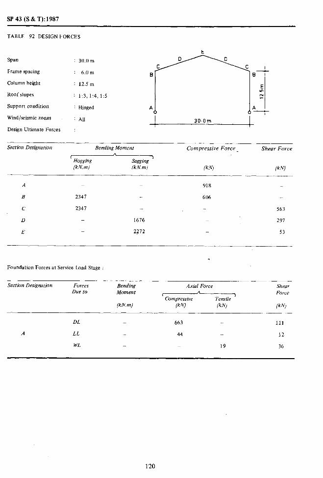
SP 43 (S & T): 1987
TABLE 92 DESIGN FORCES
t
Span : 30.0 m
Frame spacing : 6.0m B--
Column height : 12.5 m E m
Roof slopes : 1:3,1:4,1:5 z
Support condition : Hinged A 0 J A
Wind/seismic zones : All 1 30.0m
Design Ultimate Forces I
:
Section Designation Bending Moment Compressive Force _ Shear Force
r A.
Hogging Sagging >
(kN.m) (kN. m) (kN) (kN)
A _ - 918 _
B 2341 - 606 -
C 2347 - - 563
D _ 1676 _ 297
E _ 2212 _ 53
Foundation Forces at Service Load Stage :
Section Designation Forces Due to
Bending Moment
(kN. m)
Axial Force Shear
C A ) Force Compressive Tensile
(kW (kN) (kN)
DL _ 663 - 111
A LL - 44 - 12
WL - _ 19 36
120

SP 43 (S & T): 1987
TABLE 93 DESIGN FORCES
Span : 30.0 m
Frame spacing : 12.0 m
Column height : 9.5 m’
Roof slopes : 1:3,1:4,1:5
Support condition : Hinged
Wind/seismic zones : All I 30.0 m I I I
Design Ultimate Forces :
Section Designation
____
Bending Moment Compressive Force Shear Force n
’ Hogging Sagging j
(kN.m) (kN.m) (k N) lkN)
A _ - 1050
B 3070 - 873 _
C 3070 - _ 707
D _ 1847 - 365
E _ 2506 _ 64
_
Foundation Isorces at Service Load Stage :
Sectiotl Des&ration Forces Due to
Bending Moment
(kN.m)
Axial Force
-----xz Compressive
(kN) (kN)
___--- Shear Force
(kN)
DL _ 694 - 182
A I.[. _.. 87 - 32
WI, _ _~ 54 44
1’1

SP 43 (S & T):1987
TABLE 94 DESIGN FORCES
Span : 30.0 m
Frame spacing : 12.0m
Column height : 12.5,m
Roof slopes : 1:3,1:4,1:5
Support condition : Hinged
Wind/seismic zones : All I 3tSOm
Design Ultimate Forces :
Section Designation Bending Moment Compressive Force .-
Shear Force
c
Hogging Sagging ’ (kN. m) (kN. m) (kN) (kN)
A _ _ 1207 -
B 3264 _ 796 _.
C 3264 163 _ 795
D - 2475 - 420
E - 3324 - 101
. . Foundation Forces at Service Load Stage :
Section Designation Forces Due to
Bending Moment
fkN m)
Axibl Force
I Compressive
(kN) (kN)
---- Shear Force
ikN)
DL _ 832 - 146
A LL - 87 _ ‘23
WL _ - _ 74
122

SP 43 (S & T): 1987
TABLE 95 DESIGN FORCES
Span : 9.0m
Frame spacing : 6.0m
Column height : 5.0m
Roof slopes : 1:3,1:4,1:5
Support condition : Hinged
Wind/seismic zones : All
Design Ultimate Forces I :
Section Designation Bending Moment Compressive Force Shear Force
’ Hogging (kN. m)
Sagging (kN.m) /kN/ lkN)
- - 113 -
105 _ 70 -
105 40 - 71
5 75 - 35
_ - 85 20
3 49 - 55
168 _ _ 92
- _ 213 _
_ _ 242 -
Foundation Forces at Service Load Stage : .
Section Designation
_
A
Forces Due to
DL
LL
WL
Rending Moment
(kN. m)
-
-
Axial Force
r CompresSive
lkN1 (kN)
71 . -
li2 -
- -
-. Shear Force
lkNl
8
2
14
- -._
DL 145 - -
I LL 29 - _ -
WI, - 6 _ 13
123

SP43(S&T):1987
TABLI: 96 DLSIGN FORCES
E E
Span : 9.0m D F F D C GG C
I,rame spacing : 6.0m B H B
Column height : 6.5 m I-t E
Roof slopes : 1:3.1:4. 15 $1
Support condition : Hinged
Wind/seismic zones A I A
: AU
Design Ultimate Forces I 9.0m 9.0m
;--I
: I I /
Section Designation Bendirrg Moment Compressive Force Shear Force
Hoggitlg (kN. m) (kN) (kN)
- 119 -
130 _ 15 _
130 12 _ 70
12 82 _ 41
_ 90 _ 26
11 59 _ 58
194 8 _ 95
121 136 _
_ _ 254 _
.
f:oundation Forces at Service Load Stage :
Section Designation Forces Due to
Bending Moment
Axial Force
lCompressive
Shear Force
(kN.rn) (kN) (kN) (kNJ
DL _ 85 _ 5
A LL _ 11 - 1
WL _ 5 - 11
DL _ 157 - _
I LL _ 30 _ -
WL - 5 - 17
124
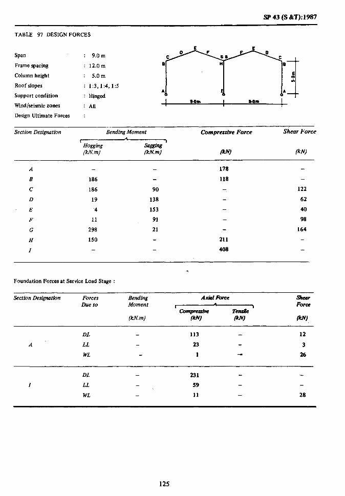
SP 43 (S &T): 1987
TABLE 97 DESIGN FORCES
Span : 9.0m
Frame spacing : 12.0m
Column height : 5.0m
Roof slopes : 1:3,1:4, I:5
Support condition : Hinged
Wmd/seismic zones I Mm I SOm I
: All r 8
Design Ultimate Forces :
Section Designation Bending Moment Compressive Force Siear Force
\ Hogging sasging ’ (kn! m) (kh?m) W) lkW
178
186 118 -
186 90 122
19 138 62
.4 153 40
11 91 98
298 21 164
150 211
408
.
Foundation Forces at Service Load Stage :
Section Designation
A
Forces Due to
DL
LL
WL
Bending Moment
(kN. m)
A&l Fc~ce shear
r Force
w (AN) 0
113 12
23 3
1 26
DL 231
I LL 59
WL 11 28
125

SP 43 (S &+):1987
TABLE 98 DESIGN FORCES
Span : 9.0m
Frame spacing : 12.0m
Column height : 6.0m
Roof slopes : 1:3,1:4,1:5
Support condition : Hinged
Wind/seismic zones : All
Design Ultimate Forces :
Section Designation Bending Moment
(Hogging (kh? m) (kn! m)
Compressive Force Shear Force
lkW (klv/
A - 185 -
B 240 129 _
c 240 154 - 121
D 34 150 - 14
E - 162 - 51
F 28 111 _ 103
G 345 43 - 168
H 243 - 218 -
I _ - 424 -
Foundation Forces at Service Load Stage :
Section Designation Forces- Due to
Bending Moment
(kN. m)
Axial Force
( Compressive
(kW lkW
Shear Force
lkW
DL - 122 - 8
A LL - 22 - 2
WL - 10 - 35
DL - 245 - -
I LL - 60 - -
WL - 8 - 35
126

SP43(S&T):1987
TABLE 99 DESIGN FORCES
Span
Frame spacing
Column height
Roof slopes
Support condition
Wind/seismic zones
: 12.0m
y;: ;;I
: 1:3,1:4,1:5
: Hinged
I 12.0m I 12.Om I Design Ultimate Forces : I
Section Designation Bending Moment Compressive Force Shear Force
sa@ing ’ (kN. m) (kN) (kN)
A - - - 174
B 192 - _ 109
c 192 20 109
D - - 127 53
E - 152 - 21
F - 84 - 76
G 313 - - 133 H 80 208 -
I _ - 353
Foundation Forces at Service Load Stage :
Section Designation
-____
Forces Due to
Bending Moment
(kN. m)
Axial Force
(Tensile Compressive (kN) (kN)
Sheqr Force
(kN)
DL _ 117 - 20
A LL - 16 - 4
WL - - 4 13
DL - 215 _ -
I LL 38 38 - -
WI, - 9 _ 15
127

SP43(S&T):W87
TABLE 100 DESIGNFORCES
span : 12.0m
Frame spacing : 6.0m
Column height : 6Sm
Roof slopes : 1:3,1:4,1:5
Support condition : Hinged
Wmd/seianiczones : All
Design Ultimate Forces :
Section D&gnation BendingMoment
m W.m) (kN.m)
Compressive Force Shear Force
(kN1 (kN)
210 -
210 54
1 143
165
94
332
127
183
111 -
108
53
25
81
138
213 -
372
.
Foundation Forces at Service Load Stage :
Section Designation Forces be to
Bending Moment
(kN. m)
Axial Force Shear
r A
1 Force Compressive Tensile
(kNl (knrl (kNl
DL 127 14
A LL 16 - 3
WL 1 17
DL - 231 - -
I LL - 39 - -
WL - 8 - 18
128

SP43(S&T):1987
TABLE 101 DESIGN FORCES
Span : 12.0m
Frame spacing : 6.0m
Column height : 9.5m
Roof slopes : 1:3,1:4,1:5
Support condition : Hinged
Wind/seismic zones : All
Design Ultimate Forces :
Section Designation Bending Moment Compressive Force Shear Force.
i f&W saaping
>
(kn! m) (kN.m) lkN) fkN)
281
281
-
-
16
465
255
- 229
- 139 -
138 121
199 71
214 - 47
132 103
- 168
- 277 -
467
Foundation Forces at Service Load Stage :
Section Designation Forces Due to
Bending Moment
(kN. m)
Axial Force Shear A
t > Force Compressive Tensile
/kN) (kN) /kN)
DL 174 8
A LL - 15 - 2
WL 9 - 16
DL - 308 -
I LL 40 -
WL - 5 25
129

SP43(S&T):1987
TABLE 102 DESIGN FORCES
Span : 12.0m
Frame spacing : 12.0m
Column height : 5.0m
Roof slopes : 1:3,1:4,1:5
Support condition
Wind/seismic zones
Design Ultimate Forces
: Hinged
: AU
:
A I I A
I 12.0m 12.Om !-I
I I I
-_ Section Designation Bending Moment
(Hogging-x (kN.m) (kN. m)
Compressive Force
(kN)
Shear Force
(kN)
A _ - 261 -
B 315 _ 172 -
C 315 73 - 183
D 13 229 _ 81
E 265 - 38
F 6 141 - 132
G 541 14 228
H 160 - 320 -
I - - 580. -
Foundation Forces at Service Load Stage :
Section Designation Forces Due to
Bending Moment
(kN. m)
Axial Force Shear
’ Compressive *
Tensile ‘, Force
(kN) (kN) (kN)
DL - 169 - 30
A LL - 32 - 8
WL - - 8 26
DL 332 - -
I LL - 76 -
WL - 18 29
130

SP 43 (S & T):1987
TABLE 103 DESIGN FORCES
E E
Span : 12.0 m
Frame spacing : 12.0m e
Column height : 6Sm
Roof slopes : 1:3,1:4,1:5
Support condition : Hinged *
Wind/seismic zones : AII
Design Ultimate Forces :
Section Designation Bending Moment Compressive Force Shear Force
r /X
Hogging Sagging 1
(kN. m) (kN.m) (kN) /kN)
- - 214 -
356 _ 177
356 139 - 181
24 255 - 89
- 288 - 52
10 168 - 141
572 ~ 9 ._ 236
255 - 329 -
- _ 603 -
.
Foundation Forces at Service Load Stage :
Section Designation Forces Due to
Bending Moment
(kN. m)
Axial Force
w Compressive
(kW lkN)
Shear Force
lkN)
DL - 180 - 25
A LL - 31 - 5
WL - - 1 35
DL _ 352 - -
I LL - 78 - -
WL - 16 36
131

!%‘43(S&T):1987
TABLE 104 DESIGN FORCES E r
I Span : 12.0m
Frame spacing : 12.0m
Column height : 9.5 m
Roof slopes : 1:3,1:4,1zs
Support condition : Hinged
Wind/seismic zones fi I
: All worn
Design Ultimate Forces :
section Designation Bending Moment Compressive Force Shear Force
t A
Hoggihg sasgins 7
(kN. m) Wm) (kN) W)
320
511 218
511 311 192
42 326 120
- 349 83
52 234 166
765 43 271
512 399
706
Foundation Forces at service Load Stage :
Section Designation Forces Due to
Bending Moment
Wm)
Ax&l Force Shear
’ Compressive n
Tensile I Force
i’kh!) (kN) P’)
DL 228 12
A LL 30 - 3
WL 19 51
DL 438
I LL 80
WL 9 40
132
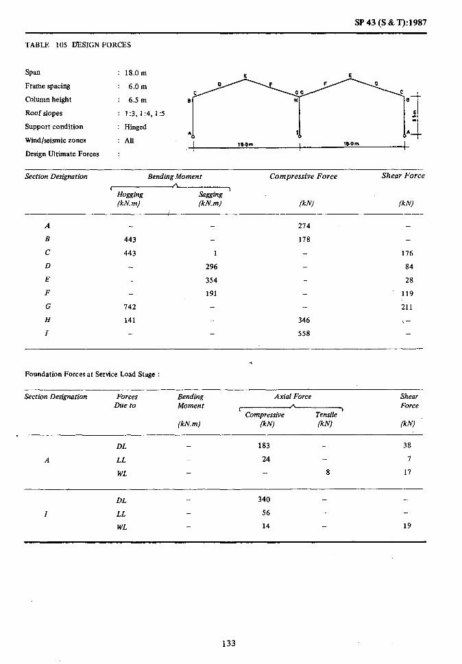
SP43(S&T):1987
TABLE 105 DESIGN FORCES
Span
Frame spacing
Column height
: 18.0m E E
: 6.0m
: 6.5 m a
Roof slopes
Support condition
Wind/seismic zones
: 1:3,1:4,1:5
: Hinged
: All
El “! -
i A7
1bOm 18.0 m
Design Ultimate Forces :
Section Designation Bending Moment
rHogging (kN. m) (kN.m)
Compressive Force Shear Force
(kN) (kN)
A - 214 -
B 443 - 178 -
c 443 1 - 176
D 296 - 84
E 354 - 28
F 191 - 119
G 142 - - 211
H 141 - 346 \-
I - 558 -
Foundation Forces at Service Load Stage :
Section DesigMtion Forces Due to
Bending Moment
(kN.m)
Axial Force
z&zP-xz (kN) (kN)
Shear Force
(kN)
DL _ 183 - 38
A LL _ 24 - I
WL - - 8 17
DL - 340 - -
I LL - 56 - -
WL - 14 - 19
133

SP 43 (S & T): 1987
TABLE 106 DESIGN FORCES
Span : 18.0m
Frame spacing : 6.0m
Column height : 9Sm
Roof slopes : 1:3,1:4,1:5
Support condition : Hinged
Wind/seismic zones : All I 18Om 18.Om
Design Ultimate Forces : I I
Section Designation Bending Moment
( (kN. m) (kNm)
Compressive Force Shear Force
(kN) (kN)
A - - 309 -
498 _
498 90
- 388
- 431
- 233
819 -
294 -
- _
194 -
_ 185
- 88
- 45
- 143
- 242
398 _
643 _
_ .
Foundation Forces at Service Load Stage :
Section Designation Forces Due to
Bending Moment
(kN.m)
Axial Force
I
(kN) (kN)
Shear Force
(k Nl
DL - 225 - 23
A LL - 23 - 4
WL - - 1 25
DL _ 409 _ -
I LL _ 58 - _
WL - 12 - 16
134

SP 43 (S &T): 1987
TABLE 107 DESIGN FORCES
Span : 18.0m
Frame spacing : 6.0m
Column height : 12.5 m
Roof slopes : 1:3,1:4, I:5
Support condition : Hinged
Wind/seismic zones : All
Design Ultimate Forces :
Section Designation Bending Moment Compressive Force Shear Force A
i 1
Hogging sagging (kN. m) (kN.m) (kNl (kN)
A - - 369 -
B
c
D
E
F
G
H
I
600 -
600 208
- 502
- 539
1 295
1117
452
-
230 -
205
109
- 69
- 174
285 491 -
772
Foundation Forces at Service Load Stage :
Section Designation Forces Due to
Bending Moment
(kN.m)
Axial Force Shear
’ Compressive h
Tensile ’ Force
(kN/ (kN) (k Nl
DL _ 278 - 16
A LL - 22 - 2
WL - 8 _ 34
DL _ 514 _ _
I LL - 60 - -
WL - 9 - 34
135
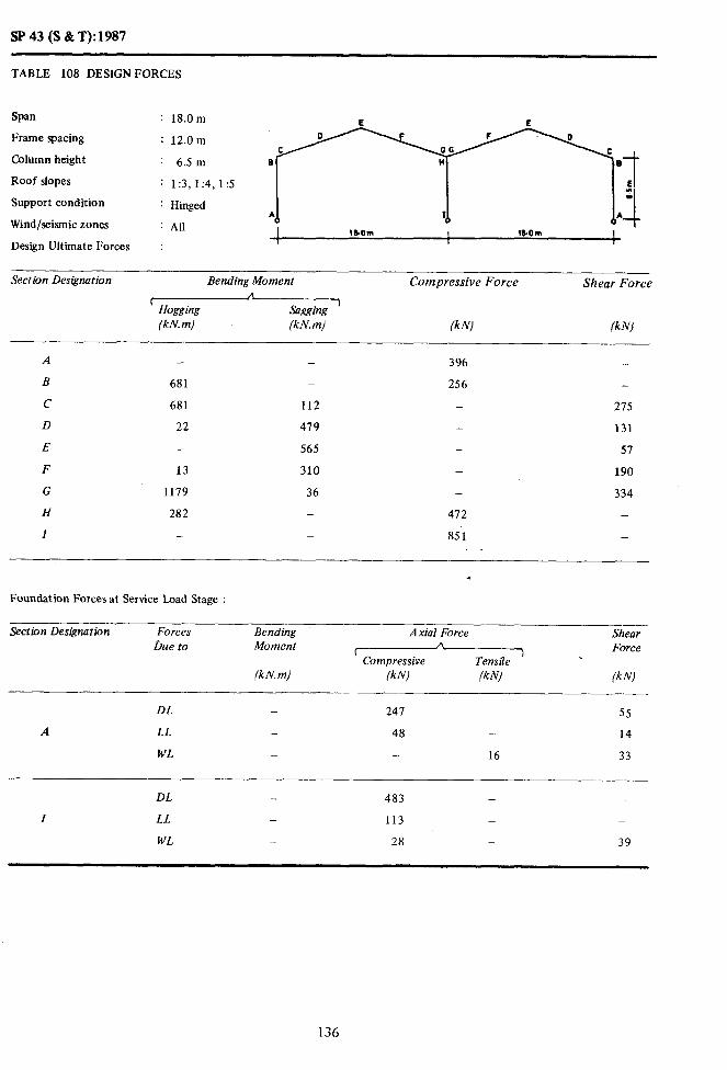
943 (S&T):1987
TABLE 108 DESIGN FORCES
Span
Frame spacing
Column height
: 18.0m
: 12.0m
Wind/seismic zones
; Alr
: Hinged
;ji
I 1bOm I 1bOm I
Design Ultimate Forces I : I
Roof slopes
Support condition
: 1:3,1:4,1:5
Section Des@ation Bending Moment Compressive Force Shear Force
I A Hogging Sagging ’ (kN. m) (kN. m) (kN) f kNl
-___
A - - 396 -
B 681 _ 256 -
C 681 112 _ 275
D 22 419 - 131
E - 565 - 57
F 13 310 190
G 1179 36 - 334
H 282 - 472 _
I - - 851 _
Foundation Forces at Service Load Stage :
Section Des&bon Forces Oue to
Bending Moment
(kN. m)
Axial Force Shear
f A
) Force Compressive Tensile
\
lkNl /k/v/ (kNl
DL - 241 _ 55
A LL _ 48 _ 14
WL _ _ 16 33
DL - 483 _ _
I LL - 113 _ _
WL - 28 _ 39
136

SP 43 (S & T): 1987
TABLE 109 DESIGN FORCES
Span
Frame spacing
Column height
Roof slopes
Support condition
Wind/seismic zones All I 1lQm I lO.Om I
Design Ultimate Forces I
--- Section Designation Bending Moment Compressive Force Shear Force
A ( Hogging Sagging ’
(kN. m) (kN. m) (kNJ fkNl - _
A
B
c
D
E
F
G
H
I
- -
812 -
812 216
9 641
_ 651
7 395
1399 _
548 -
- _
445 _
293 _
- 293
- 141
_ II
- 234
- 390
513 -
992 -
Foundation Forces at Service Load Stage :
Section Designation
_ _.-_ -
Forces Due to
Bending Moment
(kN. m)
Axial Force Shear
( Compressive P% 1 Force
Tensile
(kNJ (kN) lkNl
DL - 298 - 33
A LL - 46 - I
WL - - 2 51
______. ~_______.___
DL _ 592 _ -
I LL - 118 - -
WL _ 23 - 53
137

SP .43 (S & T): 1985
TABLE 110 DESIGN FORCES E E
Span
Frame spacing
Column height
Roof slopes
Support condition
: 18.0m
: 12.0m
: 12.5 m
: 1:3,1:4,1:5
: Hinged
Wind/seismic zones : AII I 18 om IlOm ! ’ 1 1
Design Ultimate Forces :
_____ -_ ZZGZZ5e~nation Bending Moment Compressive Force Shear Force
~g.sogging (kN. m) (kN. m) (kN) (kN)
A 522 - - -
B 1026 - 3.53 -
C 1026 511 _ 322
D - 829 _ 178
E _ 877 _ 118
F 56 512 - 281
G 1810 _ _ 457
H 909 _ 715 _
I - _ 1177 -
Foundation Forces at Service Load Stage :
Section Designation Forces Bending Axial Force __
Shear Due to Moment
(kN. m)
A Force I 1 Compressive Tensile
(kN) (kN) IkN)
DL . 375 - 22 _
A LL - 44 - 4
WL - 17 - 68
DL - 741 - -
I LL - 121 _ -
WL - 15 _ 67
138

Sf’ 43 (S &T): 1987
TABLE 111 DESIGN FORCES
E E Span : 24.0m 0 F F 0
Frame spacing : 6.0m C GG C
B a Column height : 9.5 m
Roof slopes :1 E
: 1:3,1:4,1:5 : Support condition : Hinged PI I Wind/seismic zones : AU .I
I IL.Om IL.Orn !*
Design Ultimate Forces : I , 1
Section Designation Bending Moment Compressive Force Shear Force
’ Hogging /kN. m)
\
Sagging ’ (kN. m) /kN) (kNJ
A - _ 494 -
B 1021 - 326 -
C 1021 - - 304
D - _ 720 145
E - 848 - 54
F _ 439 - 213
G 1157 _ - 371
H 294 - 669
I - - 993 -
Foundation Forces at Service Load Stage :
Section Designation Forces Due to
Bending Moment
(kN.m)
-- Axial Force Shear
n t
Tensile .I Force
Compressive
IkN) (kN) lkN)
DL _ 341 - 61
A LL - 32 - 8
WI. - - 9 25
DL - 638 - -
I LL - 76 _ -
WL _ 18 - 28
139

SP43(S&T):1987
TABLE 112 DESIGN FORCES
Span : 24.0 m
Frame spacing : 6.0m
Column height : 12.5 m
Roof slopes : 1:3, 1:4, 1:5
Support condition : Hinged
Wind/seismic zones : All
Design Ultimate Forces :
Section Designation ~-
Bending Moment Compressive Force Shear Force
C A
Hogging %aiw >
(kN. m) (kN.m) (kNl (kN)
- _
1085 -
1085 40
_ 886
_ 999
- 506
2014 _
475 -
- -
550 _
349 -
- 319
- 150
- 77
_ 246
_ 415
781 -
1119 _
Foundation Forces at Service Load Stage :
Section Designation Forces Due to
Bending Moment
(kN. m)
__- Axial Force Shear
( n
Compressive Tensile > Force
(kN) (kN) (kN)
DL - 403 - 43 .
A LL - 31 - 5
WL - - 2 33
DL - 742 _ -
I LL - 78 - -
WL - 16 - 35
140

SP43(S&T):1987
TABLE - 113 DESIGN FORCES
Span
1:rame spacing
Column height
Roof slopes
E E : 24.0 m 0 F F 0
: 12.0m C GG C
B a : 9.5 m
: 1:3.1:4,1:5 5T E
Support condition : Hinged * I Wind/seismic zones : All
2L.Orn 2LJJm
Design Ultimate Forces : I I
Section Designation Bendirlg Momerlt Shear Force
c Hogging Saggblg ’ (k&V. m) (k.1’. m) fk.\‘, (kNl
_ _ 662 -
1470 _ 435 _
1470 130 _ 438
- 1069 - 209
1246 _ - 82
- 664 _ 312
2574 - - 541 .
587 _ 852 _
- _ 1399 -
Foundation Forces at Service Load Stage :
--__ Section Designation Forces
Due to Bending Moment
(kN. m)
Axial Force
(Compressive
(kN) (kNJ
Sheor Force
(W
DL - 435 - 81
A LL - 64 _ 16
WL - _ 18 49
DL _ 839 - -
I LL _ 152 - _
WL _ 36 - 56
141

SP 43 (S &T): 1987
TABLE 114 DESIGN FORCES E E
Span : 24.0m G
Frame spacing : 12.0m
Column height : 12.5 m
Roof slopes : 1:3,1:4,1:5
Support condition : Hinged A I
Wind/seismic zones : All
Design Ultimate Forces :
Section Designation Bending Moment Compressive Force Shear Force A r ,
Hogging Sagging (kN. m) (kN. m) (kN) (kN)
-
A _ - 111
B 1676 - 510 -
c 1676 339 - 487
D 1441 - - 231
E _ - 1587 129
F 825 - _ 389
G 3171 - _ 650
H 954 - 1068 -
I - _ 1678 -
Foundation Forces at Service Load Stage :
Section Designation Forces Due to
Bending Moment
(kN. m)
Axial Force
(compressive
IkN) (kN)
Shear Force
(kN)
DL - 540 - 58
A LL - 61 _ 10
WL - - 3 67
DL _ 1054 _ -
I LL - 157 - -
WL - 30 - 70

SP 43 (S & T): 1987
TABLE 115 DESIGN FORCES
Span : 9.0m
Frame spacing : 6.0m
Column height : 5.0m’
Roof slopes : 1:3, 1:4,1:5
Support condition : Hinged
Wind/seismic zones : All I 9.0m I SOm I 9.0m I ,
Design Ultimate Forces I
:
Section Designation Bending Moment Compressive Force Shear Force A I
Hogging Sagging >
(kN. m) (kNm) (kN) (kN)
A
B
C
D
E
F
G
H
I
J
K
L
-
100
100 32
2 76
- 89
3 50
154 -
9 -
-
161
- 46
- 61
116 -
69 -
13
- 35
I- 18
53
- 90
200 -
229 _
- 90
c 48
16
Foundation Forces at Service Load Stage :
Section Designation Forces Bending Due to Moment
Axial Force
ccompressivehensi;a
Shear Force
_ (kN m) (kN) (kW (knl!
DL _ 78 - 9
A LL - 12 - 8
WL - - 2 11
--_--
DL - 138 - 1
I LL 27 - _ -
WL - 11 __ 12
143

SP43(S&T):1987
TABLE 116 DESIGN FORCES
Span : 9.0 m E L E
Frame spacing : 6.0m B
Column height : 6.5m
Roof slopes : 1:3,1:4, I:5
Support condition : Hinged *
Wind/seismic zones : All
Design Ultimate Forces :
Section Designation Bending Moment Compressive Force Shear Force *
C Hogging Sagging
)
(kN. m} (kN. m} (kN) (kN)
A
B
c
D
E
F
G
H
I
J
K
L
-
116
116
5
_
10
175
101
-
182
4
_
- 112
- 73
56 _
84 -
96 -
58 _
_ 115
- 238
_ - *
54 _
62 -
_
72
39
23
55
93
-
_
93
52
22
Foundation Forces at Service Load Stage :
Section Designation Forces Due to
Bending Moment
(kN.m)
Axial Force Shear A
’ Compressive Tensile 7
Force
(kN) (k N) (kN)
DL - 86 - 6
A LL - 12 - 1
WL - 1 - 14
DL - 148 1
I LL - 28 - -
WL - 11 14
144

SP 43 (S & T): 1987
TABLE 117 DESIGN FORCES
Span : 9.0m
Frame spacing : 12.0m
Column height : 5.0m
Roof slopes : 1:3,1:4,1:5
Support condition : Hinged
Wind/seismic zones : All 1 9.0m I 9.0m 9.0 m I 1 1
Design Ultimate Forces :
Section Designation Bending Moment Com’pressive Force Shear Force A
c ) Hogging Sagging (kN.m) (kN.m) (k N) (kN)
A - - . 182 -
B 174 115 _ _
c 174 75 126
D 13 140 - 61
E 4 161 - 37
F 12 89 - 94
G 272 21 - 159
H 134 - 199 _
I - - 383 -
J 288 21 - 159
K 7 86 1( - 85
L - 109 - 32
Foundation Forces at Service Load Stage :
Section Designation Forces Due to
.
Bending Moment
(kN. m)
Axial Force Shear Ir
[ 1 Force Compressive Tensile
(k NJ (kN) (kNl -
DL 115 - 13
A LL 24 - 4
WL 4 22
DL 216 - 1
I LL 55 - 1
WL 23 - 24
145

SP 43 (S & T): 1987
TABLE 118 DESIGN FORCES
Span
Frame spacing
Column height
Roof slopes
Support condition
Wind/seismic zones
E L E
: 9.0m B
: 12.0 m
: 6.5 m
: 1:3,1:4, 1:s
: Hinged * I
:All
Design Ultimate Forces :
Section Designation Bending Moment Compressive Force Shear Force
t * 1
Hogging Sagging (kN. m) (kN.m) (kN) (kNJ
A
B
c
D
E
F
G
H
I
J
K
L
-
210
210
19
-
26
310
204
328
12
3
-
123
154
173
106
17
-
18
102
110
189
122
-
-
125
69
46
98
163
-
163
93
43
Foundation Forces at Service Load Stage :
Section Designation Forces Due to
Bending Moment
Wm)
Axial Force Shear
c A Force
Compressive Tensile ’
(kN1 (kN) (kW
DL 124 - 9
A LL - 23 - 2
WL - 3 - 29
DL - 131 - 1
I LL 55 - -
WL - 22 - 29
146

SP 43 (S &I?& 1987
TABLE 119 DESIGN FORCES
Span : 12.0 m
Frame spacing : 6.0m
Column height : 5.0m
Roof slopes : 1:3,1:4, 1:s
Support condition : Hinged
Wind/seismic zones : All I 120m ! lI.OWl I lZ.Orn I
Design Ultimate Forces :
Section Designation Bending Moment
rHogging&X (kN. m) (kN.m)
Compressive Force Shear Force
(kN) (kN)
A - 178 -
B 197 - _ 110
c 197 12 - 112
D - 124 - 55
E - 155 - 20
F - 87 - 73
G 288 _ 129
H 12 - 298 _
-
287
-
- 338 -
- - 129
ai - % 66
199 15
Foundation Forces at Service Load Stage :
Section Designation Forces Due to
Bending Moment
(kN. m)
Axial Force
’ Compressive- (kN) (kN)
Shear Force
(kN)
DL 119 22
A LL 16 - 4
WL - - 5 11
DL - 207
I LL - 36 -
WL - 16 14
147

SP 43 (S &T):1987
TABLE 120 DESIGN I:ORCES
Span : 12.0 “I
brame spacing
Column height
Roof slopes
Support condition
Wind/seismic zones
L!$4,1:5 y;.i
I 1?.0m I lI.Om I 11om 1 Design Ultimate Forces : 1 /
Section Designation Bending Moment Compressive Force Shear Force
( A
Hogging Sagging I
(kN.m) (kN.m) (kN! (kNj
A
B
c
D
E
F
G
H
I
J
K
L
_ _
206 -
206 40
_ 142
- 171
_ 96
304 -
115 -
- _
316 -
- 89
_ 123
186 -
110 _
- 111
- 54
- 24
- 18
_ 135
175 -
353 -
_ 135
_* 71
- 21
Foundation Forces at Service Load Stage :
Section Designation Forces Due to
Bending Moment
(kN.mJ
Axial Force
’ Compressive A
Tensile ) ik N) (k NJ
Shear Force
(kN)
DL _ 129 - 15
A LL - 16 - 3
WL _ _ 3 14
DL - 222 - 1
I LL _ 36 - _
WL - 15 16
148

SP 43 (S &T): 1987
TABLE 121 DESIGN FORCES
Span : li.0 m E L E
Frame spacing : 6.0m e
Column height : 9.5 m
Roof slopes : 1:3,1:4,1:5
Support condition : Hinged
Wind/seismic zones : All *
I 12 om I 12.0m I 12 Om 1 Design Ultimate Forces :
Section Designation Bending Moment
c n
Hogging Sagging ’ (kN. m) (kN.m)
Compressive Force Shear Force
(k N) (k N)
A
B
c
D
E
F
G
H
I
J
K
L
_ _
259 -
259 102
- 202
_. 228
I 135
415 -
206 _
- -
423 _
- 118
- 143
234 -
136 -
- 125
- 69
- 38
- 99
- 163
205 _
438 _
- 163
* _ 991
_ 35
Foundation Forces at Service Load Stage :
Section Designation Forces Due to
Bending Moment
(kN.m)
Axial t;orce
’ Compressive A
Tensile ’ (kN) (k N)
Shear Force
(k N)
DL _ 176 _ 9
A LL - 15 - 2
WL - 4 - 21
DL - 293 _ 1
I LL - 31 - _
WL - 14 _ 21
149
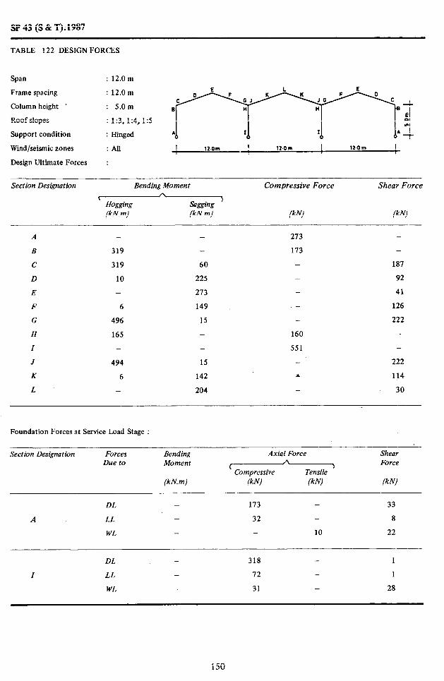
SP43 (S&T):1987
TABLE 122 DESIGN FORCES
Span : 12.0m
Frame spacing : 12.0m
Column height ’ : 5.0m
Roof slopes : 1:3,1:4, I:5
Support condition : Hinged
Wind/seismic zones :All I 12om I 12.0m I 12.0m I
Design Ultimate Forces :
Section Designation Bending Moment Compressive Force Shear Force
sagging ’ (kN.m) (kN) (kNJ
A
B
c
D
E
F
G
H
I
J
K
L
-
319
319
10
_
6
496
165
-
494
6
-
60
225
273
149
15
-
15
142
204
213 -
173 -
187
- 92
- 41
- 126
- 222
160 -
551 -
- 222
* 114
- 30
Foundation Forces at Service Load Stage :
Section Designation Forces Due to
Bending Moment
(kN. m)
Axial Force Shear A
( 1 Force Compressive Tensile
(kNJ (kN) (k I’4
DL _ 173 - 33
A LL _ 32 _ 8
WL - - 10 22
DL - 318 - 1
I LL - 72 - 1
WL - 31 - 28
150

SP 43 (S & T): 1987
TABLE 123 DESIGN FORCES
Span : 12.0m
Frame spacing : 12.0 m
Column height : 6.5 m
Roof slopes : 1:3,1:4,1:5
Support condition : Hinged
Wind/seismic zones :All I lI.OlM I II.OIlU I 1IOrn ! I I
Design Ultimate Forces :
Section Designation Bending Moment Compressive Force Shear Force 5
Hogging Sagging ’ (kN.m) (kN.m) (kNJ (kN)
A
B
C
D
E
F
G
H
I
J
K
L
-
342
342
12
11
520
130
-
541
6
-
113
255
300
168
11
-
12
159
210
281 -
175 -
- 186
- 90
- 49
- 134
- 230
293 -
569 -
- 230
z 122
- 42
Foundation Forces at Service Load Stage :
sectlon Designation Forces Due to
Bending Moment
(kN. m)
Axial Force Y-
Compressive Tensile (kN) (kN/
Shear Force
(kNJ
DL _ 183 - 22
A LL _ 32 - .6
WL _ - 6 29
DL - 336 - 2
I LL _ 73 - 1
WL _ 30 _ 32

SP 43 (S & T): 1987
TABLE 124 DESIGN FORCES
Span
Frame spacing
Column height
Roof slopes
Support condition
Wind/seismic zones
Design Ultimate Forces
12.0 m
12.0 m
12.5 m
1:3, 1:4, 1:5
Hinged
All
Section Designation Bending Moment Co,mpressive Force Shear Force
( * HOggw Sagging ’ (kN.m) (kN.m) IkN) (k N)
A
B
C
D
E
F
G
H
I
J
K
L
_
445
445
8
-
41
680
420
109
25 -
- 319
- 209
240 -
335 -
314 -
230 -
- -
- 323
- 651
_
212 ‘4 -
232 -
-
199
114
66
158
263
_
_
263
150
61
Foundation Forces at Service Load Stage :
Section Designation Forces Bending Axial Force Shear D&e to Moment
(kN. m)
A ( 1 Force Compressive Tensile
/klvl (kNl (kN)
DL _ 232 _ 13
A LL _ 31 - 3
WL _ 8 - 42
DL - 413 - 2
I LL - 74 - 1
WL - 29 - 41
152
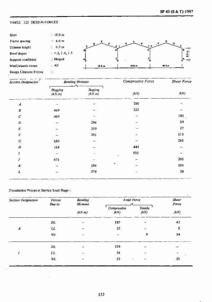
SP 43 (S % T): 1987
TABLE 125 DESIGN FORCES
Span : 18.0m
Frame spacing : 6.0m L E
Column height : 6.5 m
Roof slopes : 1:3,1:4,1:5
Support condition : Hinged
Wind/seismic zones : All 10.0 m I Il.0 m I la .o m I I
Design Ultimate Forces :
Section Designation’i Bending Moment Compressive Force Shear Force
’ Hogging (kN.m)
Sagging ’ (kN.m) f k N) lk N)
A
B
c
D
E
F
G
H
I
J
K
L
- -
469
469 -
- 286
- 359
- 201
680 -
164 -
- -
671 -
184
- 279
280
225
- 180
- 89
- 27
- 113
- 205
443
535
- 205 *
- 104
- 20
Foundation Forces at Service Load Stage :
Section Designation Forces Due to
Bending Moment
(kN.m)
Axial Force, Shear A f Force
Compressive Tensile ’ (kN) (kN) /kN)
DL - 187 - 42
A LL 25 - 8
WL - - 9 14
DL - 329 - -
Z LL - 54 - -
WL - 23 - 20
153

SF’ 43 (S & T): 1987
TABLE 126 DESIGN FORCES
Span : 18.0 m
Frame spacing : 6.0m
Column height : 9.5m
Roof slopes : 1:3,1:4,1:5
Support condition : Hinged
Wind/seismic zones :AU I 180m ! l&Om I l&O m I I
Design Ultimate Forces :
Section Designation Bending Moment
lHoaging (kN. m) (kN.m)
Compressive Force Shear Force
(k& WJ
A
B
c
D
E
F
G
H
I
J
K
L
-
495
495
-
-
198
244
-
809
-
-
58
387
451
245
-
-
218
311
316
195 -
- 191
- 92
- 39
- 137
- 235
306 -
608 -
- 255 *
- 122
- 33
Foundation Forces at Service Load Stage :
Section Designation Forces Due to
Bending Moment
(kN. m)
Axial Force Shear A
r b Force Compressive Tensile
(kN) (kN) (kW
DL - 224 - 26
A LL - 24 - 4
WL - - 5 21
DL - 390 - 2
I LL - 55 - 1
WL 23 25
154

SP43(S&T):1987
TABLE 127 DESIGN FORCES
Sean : 18.0m
Frame spacing : 6.0m
Column height : 12.5 m
Roof slopes : 1:3,1:4,1:5
Support condition : Hinged
Wind/seismic zones :AU
Design Ultimate Forces :
Section Designation Bending Moment Compressive Force Shear Force
t I\ Hokping Sagging
‘,
(kN. m) (kN.m) (klvl (kN)
-
564 -
564 144
- 512
- 577
316
999 - ,
380 -
- -
1010 _
264
- 360
.
377
228
- 212
- 108
56
- 166
- 277
469
722 -
- 277
- 147
- 49
Foundation Forces at Service Load Stage :
Section Designation Forces he to
Bending Moment
(kNm)
Axial Force
(Compressive (kN) (kN)
Shear Force
(kN)
DL 283 18
A LL - 23 3
WL - 2 27
DL - 487 2
I LL - 55 1
WL - 22 28
155

SP43(S&T):1987
TABLE 128 DESIGN FORCES
Span : 18.0m
Frame spacing : 12.0 m E L E
Column height : 6.5m
Roof slopes : 1:3,1:4,1:5
Support condition : Hinged .h
Wind/seismic zones : All 10.0 m I 18.0 m I lB.Om
Design Ultimate Forces :
Section Designation Bending Moment
%@_ (kN. m) (kN.m)
Compressive Force Shear Force
(kN) (kN)
A
B
c
D
E
F
G
H
Z
J
K
L
_
708
708
24
-
14
1079
320
-
1063
13
-
90
465
575
319
36
_
35
303
444
406
348 -
- 282
- 138
- 56
_ 180
- 324
434 _
813 -
- 324
+ 164
- 36
Foundation Forces at Service Load Stage :
Section Designation Forces Due to
Bending Moment
(kN.m)
Axial Force Shear
( A > Force
Compressive Tensile
/kN) /kN) /kN)
DL - 252 - 60
A LL _ 49 - 15
WL - _ 18 29
DL - 466 - 3
Z LL - 108 - 1
WL _ 47 - 40
156

SP 43 (S & T): 1987
TABLE 129 DESIGN FORCES
Span : 18.0 m
Frame spacing : 12.0 m
Column height : 9.5 m
Roof slopes : 1:3,1:4,1:5
Support condition : Hinged I I8OtIQ I lI.Orn II.Om I
Wind/seismic zones : All I I ,
Design Ultimate Forces :
Section Designation Bending Moment Compressive Force Shear Force
* ’ Hogging Sasging
>
(kN. m) (kN.m) (kN) (kNJ
A’ - _ ’ 456 _
B 786 _ 291 -
c 786 217 303
D - 649 146
E _ 752 70
F 4 404 222
G 1288 _ - 379
H 492 - 484 -
I - - 932 _
J 1329 _ 379 ,
K _ 372 - 198
I. _ 511 - 64
Foundation Forces at Service Load Stage :
Section Designation Forces Due to
Bending Momeit
(kN. m)
Axial Force Shear
’ Compressive A 7 Force
Tensile
(kN) (kN) (kN) -
DL - 304 -_ 36
A LL - 47 _ 8
WL - - 9 42
DL - 562 - 3
I LL _ 110 - 1
WL _ 46 _ 47
157
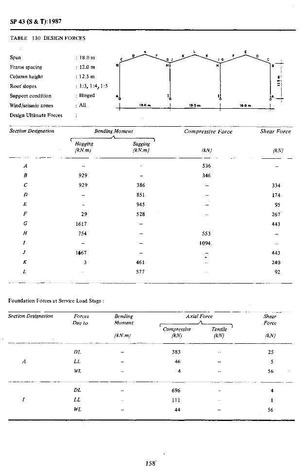
SP43(S&T):1987
TABLE 130 DESIGN FORCES
Span : 18.0m
Frame spacing : 12.0 m
Column height : 12.5 m
Roof slopes : 1:3, 1:4,1:5
Support condition : Hinged
Wind/seismic zones : All I 18.0 m I 18.0m I 18.0 m I 4 Design Ultimate Forces :
Section Designation Bending Moment
xging (kN. m) (kN.m)
Compressive Force Shear Force
lkNl (kN)
A _ - 536 -
B 929 - 346 _
c 929 386 - 334
D - 851 _ 114
E - 945 _ 95
F 29 528 _ 261
G 1611 - _ 443
H 754 - 553 -
I _ - 1094. -
J 1661 - _ 443 *
K 3 461 - 240
L - 577 - 92
Foundation Forces at Service Load Stage :
Section Designation Forces Due to
Bending Moment
(kN. m)
Axial Force Shear
t A Force Compressive Tensile
‘)
lkNl /kN) Ik N)
DL _ 383 - 25
A LL _ 46 - 5
WL _ 4 - 56
DL - 696 - 4
I LL _ 111 _ 1
WL - 44 _ 56
158
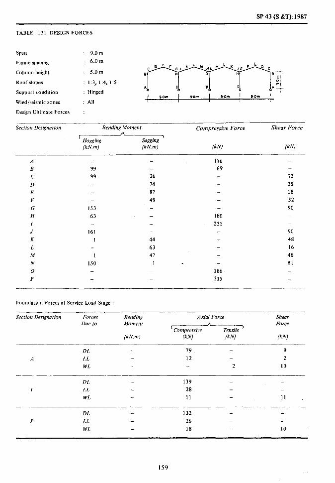
SP 43 (S &T):1987
TABLE 131 DESIGN FORCES
Span
Frame spacing
Column height
Roof slopes
Support condition
Wind/seismic zones
Design Ultimate Forces
9.0 m
6.0 m
5.0m
1:3, 1:4, 15
Hinged
All
Section Designation Bending Moment
’ (kN. m) (kN.m)
Compressive Force Shear Force
(kN) (k-w)
A
B
c
D
E
F
G
H
I
J
K
L
M
N
0
P
_
99
99 _
__ _
153
63 -
161
1 -
1
150 -
-
26
14
87
49 - _ -
44
63
47
I
116
69 - - - _ -
180
231
-
- s _
186
215
_
13
35
18
52
90 -
_
90
48
16
46
81 -
b’oundation Forces at Service Load Stage :
Section Designation Forces Due to
Bending Moment
(kN.m)
Axial Force A
’ Compressive Tensile )
(kN) (k N)
Shear Force
(k N)
DL - 79 - 9
A LL - 12 - 2
WL - 2 10
__-__ ____ DL - 139 _ -
I LL 28 - -
WL 11 - 11
DL - 132 - -
P LL - 26 _ -
WI. 18 - 10
159

SP43(S&T):1987
TABLE 132 DESIGN FORCES
Span : 9.0 m
Frame spacing : 6.0m
Column height : 6.5m
Roof slopes : 1:3. I :4, I:5
Support condition : Hinged
Wind/seismic zones : All 1 9,Om ] 9.Om 1 9.Om ’ 9.Om ’ , .
Design Ultimate Forces :
Section Designation Bending Moment
‘Hogging A
Sagging ) (kN.m) (kN.tn)
Compressive Force Shear Force
(kN) (kNl
A
B
c
D
E
F
G
H
I
J
K
L
M
N
0
P
-
109 109
1 -
I 163 90 -
180 2
-
2
168
84 -
-
41
83
94
56 -
-
-
51 65
54 _
- _
122
71 -
115 241
179 222
-
12
38
22
55
93 _
-
93
51 22
50
84 -
- -
Foundation Forces at Service Load Stage :
Section Designation -
Forces Bending Axial Force Shear Due to Moment Force
Compressive (kN. m) (kN) (kN) (kNl
DL _ 86 _ 6
A LL - 12 - 1 WI, _ - - 13
DL - 150 - -
I LL - 26 - -
WL - 10 - 12
DL _ 141 - -
P LL 26 - -
WL - 18 - 12
160

SP43(S&T):1987
TABLE 133 DESIGN FORCES
Span : 9.0m
Frame spacing : 12.0 m
Column height : 5.0m
Roof slopes : 1:3, 1:4, 1:5
Support condition : Hinged
Wind/seismic zones : All
Design Ultimate-Forces :
yJ;-$
I Born I s.om I s.om ! s.om 1 I I I I
Section Designation * Bending Moment Compressive Force Shear Force
‘Hogging (kN. m)
A
Sagging ’ (kN.m) WV WV
A
B
c
D
E
F
G
H
I
J
K
L
M
N
0
P
_
169 169
9 4
8
270
7 -
287
7
3
7
270
104 -
-
64
i3i
159 88
21 _ -
21 83
111 85
, 21 -
182 114
_ - - - -
355
387 _
- - - -
207
357
-
126 61 36 94
159 - -
159 84 32 82
142 -
.
Foundation Forces at Service Load Stage :
Section Designation Forces Due to
Bending Moment
(kN.m)
Axial Force
(Compressive Tensile ) (kN) (kNl
Shear Force
(kNl *
DL - 116 14
A LL - 24 - 4
WL - _ 5 20
DL - 220 - _
I LL - 56 - _
WL - 21 21
DL - 207 -
P LL - 51 -
WI. _ 36 - 19

SP 43 (S & T): 1987
TABLE 134 DESIGN FORCES
Span : 9.0m
Frame spacing : 12.Om
Column height : 6.5m
Roof slopes : 1:3, 1:4, 1x5
Support condition : Hinged
Wind/seismic zones : All 1. 9,Om 1 9.0 m ] 9.Om I. 9.Om ’ I I *
Design Ultimate Forces :
Section Designatiorl Bending Moment Compressiw Force Shear Force
e-soaninn (kN.mJ (kN.mJ IkNJ WJ
A
B
c
D
E
F
G
H
I
J
K
I.
M
N
0
P
-
194
194
10 _
21
288
180 -
322
8
2
01
305
170 _
-
103
152
170
102
117 _
_
18
97
113
99
20
189 -
119 _
- 125
- 67
- 44
- 98
164 199 -
400 _
_ 164
- 91
- 43
-, 89
_ 149 311 -
366 -
Foundation Forces at Service Load Stage :
Section Designation Forces Due to
Bending Moment
(kN.mJ
Axial Force Shear
(Compressive Force
Tensile 1
WJ SW WJ
DL - 124 _ 9
A LL _ 23 _ 3
WL _- 1 _ 26
DL - 233 -
I LL - 56 _ -
WI‘ - 20 _ 25
DL - 216 _ _
P LL - 51 - _
WI, - 37 _ 23
162

SP 43 (S & T): 1987
TABLE 135 DESIGN FORCES
Span
I;ramc spacing
Column height
Root’ slopes
: 12.0m
: 6.0m
: S.Om -k-
: 1:3,1:4,.1:5 E n 0 H a El
01
Support condition : Hinged * I P I 6A y
Wind/seismic zones : All I 12 Om I 12.0 m I 12 Om I 12.0 m ! 1
Iksign Uttimatc I:orces :
A 180
R 204 III -
L 204 5 _ 113
D 120 _ 56
I: 153 20
Is’ 89 _ 71
(; 2HB - 128
II 95 273 -
I -.. 340
J 290 _ 128
K 77 66
I‘ - 119 - 15
M _ 82 * - 64 IV 273 _ 118 0 - _ - P
-
284
324
Section Designation Bending Moment Compressive Force Shear Force
t A Ilogging &xing
1
(kN.m) (kN.m) (k N) (kN)
I%undation I:orccs at Service Load Stage :
Section Designation
A
Forces Due to
DL
LL
WL
Bending Moment
(kN. m)
-
-
-
Axial Force Shear
I A Force Compressive Tensile
1
(W W) (W
120 - 23
17 _ 5 - 6 10
DL - 208 - 2 I LL _ 36 - -
WL _ 115 _ 3
DL _ 201 - -
P LL - 34 _ -
WL - 23 - 10
163

SP 43 (S & T):1987
TABLE 136 DESIGN FORCES
Span : 12.0m
Frame spacing
Column height
Roof slopes
: 6.0m E L L E 0 F II Y M K F D
C C J NN J G C
: 6.5 m B 8t
0 N B
E : 1:3, 1:4,1:5 In ti
Support condition : Hinged A I P I 0-c
i
Wind/seismic zones : All 12.0 m I 12.0 m I
12.Om 12.0m
I I
Design Ultimate Forces :
Section Designation Bending Moment Compressive Force Shear Force A ’ 1
Hosing sagg~g (kN.m) (kN.m) /kN) Ik N)
A - - 187 - B 206 - 110 -
C 206 30 - 112 D - 139 - 5.5 E - 169 - 24 F - 96 - 77 G 302 - - 134 H 114 - 277 - I - - 356 -
J 317 . 134 K - 85 - 71 L - 126 - 22 M - 92 --* 68 N 294 - 121 0 92 - 274 - P 335 - - _
Foundation Forces at Service Load Stage :
Section Designation Forces Due to
Bending Moment
(kN. m)
Axi Force A
Tensile ’ ’ Compressive (kN) (k N)
Shear Force
(kN) ._.
DL - 130 16
A LL 16 3 WL - - 4 13
DL 223 1
I LL - 37 -
WL 14 - 14
DL 213 - -
P LL 34 - -
WL 23, - 12
164
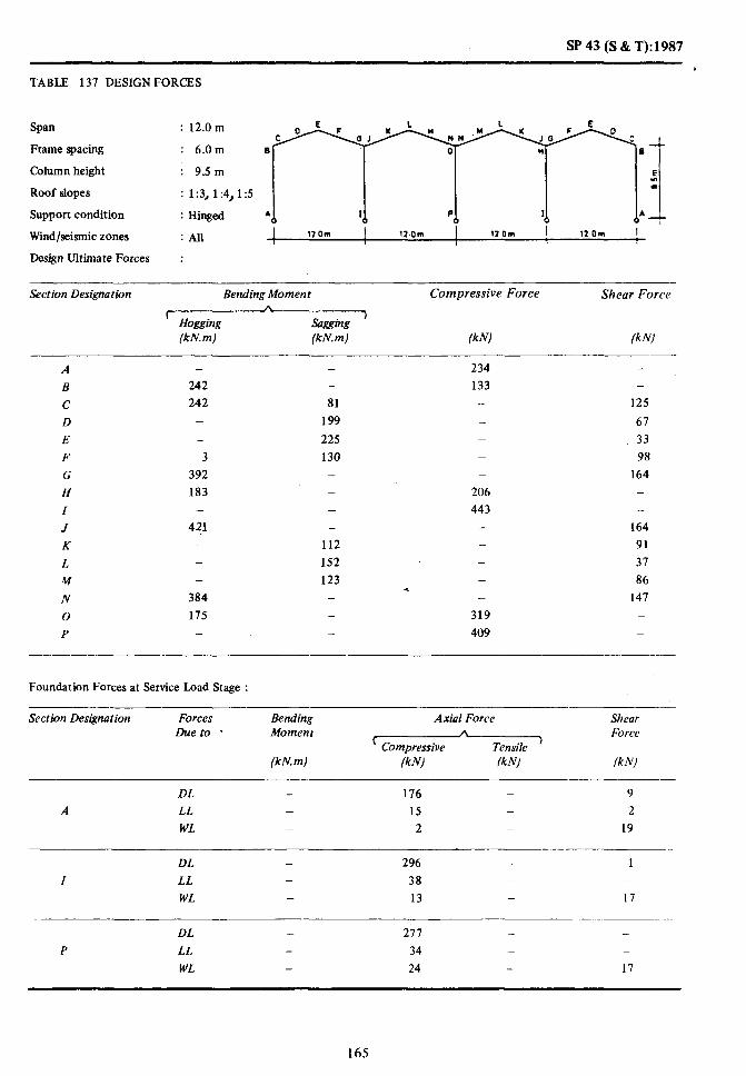
TABLE 137 DESIGN FORCES
Span : 12.0m
Frame spacing : 6.0m
Column height : 9Sm
Roof slopes : 1:3, 1:4,1:5
Support condition : Hinged
;;:;
Wind/seismic zones :All I 12Om I 12.Om 12 Om 12.0m ! I 8 /
Design Ultimate Forces :
Section Designation Bending Moment Compressive Force Shear Force
I- /r
Hogging &zing 1
(kN. m) (kN.m) (kN) lkN)
A _ - 234 B 242 - 133 C 242 81 -
D - 199 - E - 225 - F 3 130 _ G 392 - _
H 183 _ 206 I - _ 443 J 4?1 - - K - 112 - L - 152 _ w - 123 -
* N 384 - -
0 175 - 319 P - - 409
Foundation Forces at Service Load Stage :
- _
125
67 33 98
164 _ -
164 91 37 86
147 _ _
Section Designation Forces Bending Duet0 - Moment
Axial Force *
’ Compressive Tensile ’
Shear Force
(kN.m) (kN) /kN) (kN)
DL - 176 _ 9
A LL - 15 _ 2
WL _ 2 _ 19
DL _ 296 .- 1 I LL - 38 - _
WL - 13 - 17
DL - 277 - -
P LL - 34 _ _
WL - 24 - 17
165

SP 43 (S & T): 1987
TABLE 138 DESIGN t:ORCES
SpaIl : 12.0 m
t:ramc spacing
Column height
Roof slopes
Support condition
: 12.0 m
: 5.0m e
: t :3. 1:4, t :5
: Hinged * I PA 2
Wind/seismic zones : At1 I 12.0 Ul I 12.0 m I 12.0 m I 12.0 m ! 1 I l-
Design Ultimate t:orces
Bending Moment
C,H , (kN.m) (kN. m)
C’ompressive bi)rce Shear Force
(kb, (kN)
A
B
c D
E
F
G
H
I
J
K
L
M
N
0
P
-
321
321
11 -
6
489
22 -
491
6 -
6
471
-
48
218
269
152
15 -
-
15
136
203
143
15 -
216
174
- - -
496
555
-
*- -
479
524
-
189
93
41
124
220 -
-
220
113
30
110
199 -
Foundation Forces at Service Load Stage :
Section Designation Forces Due to
Bending Moment
(kN. m)
Axial Force Shear A
( Compressive Force
Tensile >
(kNJ (kNJ (kN)
DL - 174 - 34 A LL - 33 - 9
WL - _ 11 21
DL - 320 - 2
I LL _ 13 - -
WL _ 29 _ 26
DL _ 306 - -
P LL - 68 -
WL - 46 - 21
166

SP 43 (S & T): 1987
TABLE 139 DESIGN FORCES
Span : 12.0m
Frame spacing : 12.0 m E I. 1 E 0 F Y Y F
C t 1 K
NW K
J G D c
Column height : 6.5 m B n 0 H e
E
Roof slopes : 1:3, 1:4,1:5 s
Support conditibn : Hinged A
Wind/seismic zones : All I;1
I P I i
Il.0 m 12.0 m lY.Om 1EOm
1 i I I Design Ultimate Forces :
Section Designation Bending Moment Compressive Force Shear Force
( A 1
Hogging Sagging (kN. m) (kN. m) (kN) (kN)
A B c D E F G H Z J K L M N 0 P
338
338
6
5 520 194
-_
541 6
5 510 185
-
-
94
250
296 166
11 - -
11 152 216 160
14
282 - 175 -
- 187 - 91 - 48 - 133 - 229
287 -
574 - 229 - 121 - 42 - 117
* 206
458 535 -
Foundation Forces at Service Load Stage :
Section Designation Forces Bending Due to Moment
Axial Force n
’ Compressive Tensile ’
Shear Force
(kN.m) (kN) (kN) (kN)
DL - 184 - 23 A LL - 32 - 6
WL - - I 26
DL - 338 _ 1 Z LL - 74 - -
WL - 29 - 28
DL - 300 - -
P LL - 68 - -
WL - 47 - 25
167

SP 43 (S& T):1987
TABLE 140 DESIGN FORCES
Span : 12.0m
Frame spacing : 12.0m
Column height : 9.5 m
Roof slopes : 1:3, 1:4, 15
Support condition : Hinged
Wind/seismic zones : All
Design Ultimate Forces :
y%T:]
I 12 On, I 11.0m I Worn I lZ.Om I
Section Des&nation Bending Moment Compressive Force Shear Force
c A
Hogging Wxing >
(kN.m) (kN.m) /kN) (kN)
A - - 327 B 409 - 203 -
c 409 197 - 199
D - 330 109 E - 368 - 62
F 31 221 - 146
G 636 - - 263
H 369 - 324 -
I - - 667 -
J 699 - __ 263
K 14 200 148 L - 242 68 M 13 210 T 142
N 649 240 0 354 - 503 -
P - - 610 -
Foundation Forces at Service Load Stage :
Section Designation Forces Due to
Bending Moment
(kn! m)
Axial Force
C
(klvl /kN)
Shear Force
/kN)
DL - 232 - 13
A LL - 31 _ 3
WL _ 4 - 37
DL - 417 - 1
I LL - 75 - -
WL 26 - 35
DL - 387 - -
P LL - 68 -
WL - 49 - 33
168

SP43(S&T):1987
TABLE 141 LOCATION OF JOINTS AND LIFTING POINTS DURING TRANSPORTATION
AND ERECTION (REFER FIG. 150)
(a) For Gable FZames with Rxed Bases
Spcln
(ml
Sprrdng
(m)
Column Height
(m)
Slope a
I IN (mm)
b
(mm)
9 6 5.0
9 6 5.0
9 6 5.0
9 6 6.5
9 6 6.5
9 6 6.5
9 12 5.0
9 12 5.0
9 12 5.0
9 12 6.5
9 12 6.5
9 12 6.5
12 6 5.0
12 6 5.0
12 6 5.0
12 6 6.5
12 6 6.5
12 6 6.5
12 6 9.5 *
12 6 9.5
12 6 9.5
12 12 5.0
12 12 5.0
12 12 5.D
12 12 6.5
12 12 6.5
12 12 6.5
12 12 9.5
12 12 9.5
12 12 9.5
18 6 6.5
18 6 6.5
18 6 6.5
18 6 9.5
18 6 9.5
18 6 9.5
Note - Distances a and b are same in single bay and multi-bay frames.
3 1436 1760
4 1403 1720
5 1388 1700
3 1452 1950
4 1419 1950
5 1403 1980
3 1468 2140
4 1434 2180
5 1419 2250
3 1468 2140
4 1434 2180
5 1419 2250
3 1942 2690
4 1898 2720
5 1817 2190
3 1942 2690
4 1898 2720
5 1877 2790
3 1942 2690
4 1898 2720
5 1877 2790
3 1942 2690
4 1898 2720
5 1877 2790
3 1942 2690
4 1898 2720
5 1877 2790
3 1942 2690
4 1898 2120
5 1877 2790
3 2923 4170
4 2857 4270
5 2826 4420
3 2923 4170
4 2857 4270
5 2826 4420
(Contfnued)
169

SP 43 (S & T): 1987
TABLE 141 LOCATION OF JOINTS AND LIFTING POINTS DURING TRANSPORTATION AND ERECTION (REFER FIG. 150) - Contd
Span Spacing
hJ (mJ
Column Height
(ml
Slope
I IN
a
(mm)
b
(mm)
18 6 12.5 3
18 6 12.5 4
18 6 12.5 5
18 12 6.5 3
18 12 6.5 4
18 12 6.5 5
18 12 9.5 3
18 12 9.5 4
18 12 9.5 5
18 12 12.5 3
18 12 12.5 4
18 12 12.5 5
24 6 9.5 3
24 6 9.5 4
24 6 9.5 5
24 6 12.5 3
24 6 12.5 4
24 6 12.5 5
24 12 9.5 3
24 12 9.5 4
24 12 9.5 5
24 12 12.5 3
24 12 12.5 4
24 12 12.5 5
30 6 9.5 3
30 6 9.5 4
30 6 9.5 5
30 6 12.5 3
30 6 12.5 4
30 6 12.5 5
30 12 9.5 3
30 12 9.5 4
30 12 9.5 5
30 12 12.5 3
30 12 12.5 4
30 12 12.5 5
Note - Distances a and b are same in single bay and multi-bay frames.
2923
2857
2826
2923
2857
2826
2923
2857
2826
2923
2857
2826
3903
3815
3774
3903
3815
3774
3903
3815
3774
+ 3903
3815
3774
4852
4743
4692
4852
4743
4692
4852
4743
4692
4852
4743
4692
4170
4270
4420
4170
4270
4420
4170
4270
4420
4170
4270
4420
5650
5810
6040
5650
5810
6040
5650
5810
6040
5650
5810
6040
6750
6890
7110
6750
6890
7110
6750
6890
7110
6750
6890
7110
(Continued)
170

SP 43 (S & T):1987
TABLE 141 LOCATION OF JOINTS AND LIFTING POINTS DURING TRANSPORTATION AND ERECTION (REFER FIG. 150) - Contd
fb) For Amble Frames with Hinged Bases
Span
fW
Spacing
(ml
Column Height
W
Slope a b
1 IN (mm) @ml
9 6 5.0 3 1436
9 6 5.0 4 1403
9 6 5.0 5 1388
9 6 6.5 3 1436
9 6 6.5 4 1403
9 6 6.5 5 1388
9 12 5.0 3 1436
9 12 5.0 4 1403
9 12 5.0 5 1388
9 12 6.5 3 1436
9 12 6.5 4 1403
9 12 6.5 5 1388
12 6 5.0 3 1926
12 6 5.0 4 1883
12 6 5.0 5 1862
13 6 6.5 3 1926
12 6 6.5 4 1883
12 6 6.5 5 1862
12 6 9.5 3 1926
12 6 9.5 4 1883
12 6 9.5 *
5 1862
12 12 5.0 3 1926
12 12 5.0 4 1883
12 12 5.0 5 1862
12 12 6.5 3 1926
12 12 6.5 4 1883
12 12 6.5 5 1862
12 12 9.5 3 1926
12 12 9.5 4 1883
12 12 9.5 5 1862
18 6 6.5 3 2815
18 6 6.5 4 2810
18 6 6.5 5 2180
18 6 9.5 3 2875
18 6 9.5 4 2810
18 6 9.5 5 2780
2430
2510
2740
2430
2570
2740
2430
2570
2740
2430
2570
2740
3010
3130
3290
3010
3130
3290
3340
3560
3810
3340
3560
3810
3340
3560
3810
3340
3560
3810
4280
4430
4620
4450
4640
4880
Note - Distances a and b are same in single bay and multi-bay frames. (Continued)
171

!P 43 (S & T):1987
Span
(ml
TABLE 141 LOCATION OF JOINTS AND LIFTING POINTS DURING TRANSPORTATION
AND ERECTION (REFER FIG. 150) - Co&.
Spacing Column Slope a Height
@, (ml 1 IN @ml
b
(mm)
c
18
18
18
18
18
18
18
18
18
18
18
18
24
24
24
24
24
24
24
24
24
24
24
24
30
30
30
30
30
30
30
30
30
30
30
30
6 12.5 3
6 12.5 4
6 12.5 5
12 6.5 3
12 6.5 4
12 6.5 5
12 9.5 3
12 9.5 4
12 9.5 5
12 12.5 3
12 12.5 4
12 12.5 5
6 9.5 3
6 9.5 4
6 9.5 5
6 12.5 3
6 12.5’ 4
6 12.5 5
12 9.5 3
12 9.5 4
12 9.5 5
12 12.5 3
12 12.5 4
12 12.5 5
6 9.5 3
6 9.5 4
6 9.5 5
6 12.5 3
6 12.5 4
6 12.5 5
12 9.5 3
12 9.5 4
12 9.5 5
12 12.5 3
12 12.5 4
12 12.5 5
2815
2810
2780
2815
2810
2780
2815
2810
2780
2815
2810
2780
3040
3754
3713
3840
3754
3713
3840
3154
3713
. 3840
3754
3713
4812
4704
4654
4812
4704
4654
4812
4754
4704
4812
4754
4704
4780
5060
5400
4450
4640
4880
4780
5060
5040
5280
5700
6180
5740
5950
6230
5910
6160
6490
5910
6160
6490
6410
6800
7270
6870
7060
7330
7210
7480
7850
7210
7480
7850
7210
7480
7850
Note - Distances u and b are same in single bay and multi-bay frames.
172

TABLE 142 DETAILS OF TYPE (1) JOINT IN THE RAFTER (REFER FIG. 152)
Sl. Rafter Section
Iv0 (Width mm mm
MS Plate Size
mm
Diameter of Number of MS Number of MS Number of Rows a b C d e
MS Rods Rods in Each Rods in One Half Row
mm mm mm mm mm mm mm mm mm
1 200 400 200 x 380 x 6 16 4 2 2 30 40 70 50 100
2 250 500 250 x 420 x 8 18 6 3 2 35 45 80 60 100
3 300 600 300 x 520 x 10 18 9 3 3 40 45 80 60 100
4 400 800 400 x 620 x 12 22 12 4 3 50 60 80 60 120
5 400 1000 400 x 640 x 16 2s 12 4 3 50 65 80 60 120
6 500 800 500 x 640 x 12 25 12 4 3 50 65 80 60 120
I 500 900 500 x 560 x 14 28 10 5 2 60 70 90 70 120
8 500 1000 500 x 780 x 16 32 9 3 3 70 80 100 80 120
9 500 1200 500 x 810 x 18 32 12 4 3 IO 80 100 80 150
10 500 1500 500 x 870 x 25 36 42 4 3 15 90 105 85 150
11 600 1100 600 x 810 x 18 32 12 4 3 70 80 100 80 150
12 600 1200 600 x 870 x 18 36 12 4 3 15 90 105 85 150
13 600 1500 600 x 750 x 25 42 10 5 2 80 110 110 90 150
14 750 1100 750 x 970 x 18 42 9 3 3 80 110 110 90 150
15 750 1300 150 x 970 x 20 42 12 4 3 80 110 110 90 150
16 750 1500 750 X 970 X 25 42 12 4 3 80 110 110 90 150

Bays Span Spacing
e TABLE 143 ESTIMATION OF QUANTITIES
G
Frames with Hinged Bases *
3
Column Height Quantity of Concrete (m3/m2) Quantity ofSteel (kg/m’) ;;
t 6 A 3 In Frames In Fkines, etc
‘) c Frames Purl&, etc.
I
HY~ (m) (m) (m)
3 12 6 9.5 0.1538 0.0327 13.810 4.444
12 12 5.0 0.0613 0.0688 5.039 5.396
12 12 6.5 0.0665 0.0717 5.669 5.625
12 12 9.5 0.0769 0.07748 7.882 6.079
2.153
2.273
2.514
18 6 6.5 0.1071 0.0250 8.883 3.472
18 6 9.5 0.1318 0.0268 11.571 3.694
18 6 12.5 0.0710 0.0240 15.605 3.917
18 12 6.5 0.0590 0.0652 5.556 5.108
18 12 9.5 0.0776 0.0690 8.776 5.412
18 12 12.5 0.1045 0.0729 10.546 5.716
-
2.022
2.182
2.343
4 9 6 5.0 0.0480 0.0285 7.958 3.953
9 6 6.5 0.0923 0.0300 9.199 4.120
9 12 5.0 0.0513 0.0741 4.604 5.810
9 12 6.5 0.0562 0.0770 5.313 6.039
-
2.306
2.426
12 6 5.0 0.0985 0.0270 7.823 3.781
12 6 6.5 0.1069 0.0281 ‘8.837 3.906
12 6 9.5 0.1497 0.0301 13.132 4.156
12 12 5.0 0.0602 0.0659 4.679 5.168
12 12 6.5 0.065 1 0,0681 5.797 5.339
12 12 9.5 0.0878 0.0724 8.319 5.681
2.033
2.123
2.304
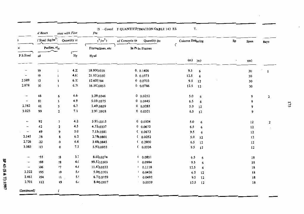
. . - _
:c
P.S.Steel ’
--
-- me- :S - Contd F QUANTITIWIMATION OABLE 143 ES T.
d Bases 1n1.5 wirh Fixe Fro __- --- ~ f SAeel (kg/m’: Quantity 01 n3/m2) of Concrete (n Quantity ;ht Column Hei&& SP Span
Purlins, e\s c
In n In Frames &
r sd HY Hysd
(m) (m) I Cm) __c-
-
-
2.589
2.818
J9 i 4.2: 18.90$0316 0. 0.1406 9.5 fj
59 I 4.6: 21.93:,0350 0. 0.1573 12.5 6
$3 1 6.1! 12.6Ot.784 0 0.0703 9.5 12
JO 3 6.7( 16.5Oz.0853 0 0.0786 12.5 12
- 18 6 4.61 3291.0346 0 0.0252 5.0 6
- 81 5 4.9’ 5.05t.0375 0 0.0445 6.5 6
2.782 41 5 6.7, 2.49i.0859 0 0.0283 5.0 12
3.023 99 2 7.1 2.911.0918 0 0.0321 6.5 12
-
-
2.545
2.126
3.083
92 7 4.2 3.911.0315 0 0.0504 5.0 6 12
42 2 4.5 4.72~0331 0 0.0672 6.5 6 12
49 9 5.0 7.13~0381 c 0.0672 9.5 6 12
.78 8 6.2 2.7%0801 ( 0.0252 5.0. 12 12
I22 0 6.6 3.661.0845 ( 0.2800 6.5 12 12
i13 0 1.3 5Jw.0933 ( 0.0336 9.5 12 12
-
-
-
2.222
2.461
2.701
‘55 !8 3.7 8.03.0274 t 0.0851 6.5 6 18
I88 !8 4.c 99.5:x0303 ( 0.0984 9.5 6 18
iO6 ‘7 4.t 11.43.0332 ( 0.1118 12.5 6 18
195 19 5.‘ 5.w.0701 ’ 0.0426 6.5 12 18
354 11 5.! 6.7b.0759 ’ 0.0492 9.5 12 18
112 19 6.4 8.%.0817 0.0559 12.5 12 18
30
30
30
30
‘Continued) -
-
bYS
1
2
2

Bays Span
(m)
Spacing
W
%
8 TABLE 143 ESTIMATION OF QUANTITIES - Confd 8
r@ Frames with Fixed Bases ti-
Quantity of Concrete (m3/m2) .L
Column Height Quantity of Steel (kg/m?)
IIn ( A 3
) , Frames Purlins, etc
c A
Hysd Hysd P.S.Steel ) (ml
2 24 6 9.5 0.1373 0.0273 12.385 3.743
24 6 12.5 0.1529 0.0295 16.351 3.993
24 12 9.5 0.0687 0.0698 17.880 5.577 2.226
24 12 12.5 0.0765 0.0742 9.578 5.818 2.406
2
3 9 6 5.0 0.0239 0.0306 3.265 4.198
9 6 6.5 0.0420 0.0326 4.574 4.414
9 12 5.0 0.0269 0.0781 2.290 6.123 2.466
9 12 6.5 0.0303 0.0820 3.176 6.429 2.623
3 12 6 5.0 0.0483 0.0286 3.676 3.954 -
12 6 6.5 0.0533 0.0301 4.481 4.125
12 6 9.5 0.0633 0.0330 6.292 4.458
12 12 5.0 0.0241 0.0742 2.789 5.815 2.306
12 12 6.5 0.0266 0.0772 2.847 6.046 2.421
12 12 9.5 0.0316 0.0830 5.148 6.507 2.664
18 6 5.6 0.0819 0.0250 7.599 3.475
18 6 6.5 0.0937 0.0269 9.145 3.698
18 6 9.5 0.1056 0.0289 11.528 3.920
18 12 5.0 0.0409 0.0652 4.823 5.113
18 12 6.5 0.0469 0.069 1 6.116 5.418
18 12 9.5 0.0528 0.0730 8.163 5.724
-
2.022
2.182
2.341
(Continued)

TABLE 143 ESTIMATION OF QUANTITIES - Co&d
? Frames with Fixed/Hinged Bases
Bays Span Spacing Column Height Quantity of Concrete (m’/m’) Quantity of Steel (kg/m’)
Mv ( A > In Frames In Purlines, etc Frames purlins, etc
Hysd
(ml (ml (ml
4 9 6 5.0 0.0233 0.0287 3.153 3.968
9 6 6.5 0.0408 0.0301 4.296 4.134
9 12 5.0 0.0262 0.0742 2.431 5.815
9 12 6.5 0.0294 0.0772 2.870 6.046
-
-
2.306
2.424
12 6 5.0 0.0472 0.0271 3.490 3.788
12 6 6.5 0.0519 0.0282 4.410 3.913
12 6 9.5 0.0613 0.0304 6.003 4.163
12 12 5.0 0.0236 0.0713 2.701 5.583
12 12 6.5 0.0260 0.0735 3.184 5.757
12 12 9.5 0.0307 0.0779 3.906 6.102
-
-
-
2.184
2.274
2.455
1 6 5.0 0.1007 0.0483 19.611 6.315
6 6.5 0.1096 0.0541 12.519 6.981
12 5.0 0.0611 0.1160 6.546 9.102
12 65 0.0688 0.1276 7.056 10.019
-
-
3.954
4.426
12 6 5.0 0.1154 0.0398 9.514 5.278
12 6 6.5 0.1290 0.0440 11.792 5.778
12 6 9.5 0.1868 0.0525 21.375 6.674
12 12 5.0 0.0700 0.097 1 6.104 7.625
12 12 6.5 0.0778 0.0105 7.257 8.313
12 12 9.5 0.1088 0.123.1 11.236 9.681
-
-
3.264
3.625
4.347
(Continued)

-
steel ’
-
:.392
1.573
!.934
-
-
-
..222
!.463
!.701
5.028 15.285 $1 0.03Il621 0. 9.5 6 12 2
5.851 5.3194 16 0.07‘0635 0. 5.0 12 12
6.194 6.309 39 0.0710693 0. 6.5 12 12
6.878 8.674 16 0.08’0965 0. 9.5 12 12
3.750 9.255 13 0.02:1107 0. 6.5 6 18
4.079 12.861 Dl 0.03(1373 0. 9.5 6 18
4.412 15.912 30 0.03,1792 0. 12.5 6 18
5.488 5.877 DO 0.07!0608 0 6.5 12 18
5.944 7.972 57 0.07.0807 0 9.5 12 18
6.398 10.264 15 0.08.1093 0 12.5 12 18
- 3.740 15.865 72 0.02.1664 0 9.5 6 24 2 - 3.986 18.025 93 0.02.1968 0 12.5 6 24
2.227 5.469 9.646 97 0.06.0900 0 9.5 12 24
2.406 5.809 11.734 4 0.07.1201 0 12.5 12 24
- 4.173 8.265 804 0.03.0858 a 5.0
- 4.395 9.086 123 0.03.0947 a 6.5
2.466 6.114 4.781 ‘80 0.01.0524 u 5.0
2.627 6.420 5.565 119 0.08.0576 C 6.5
-
-
nrinued)
3.949 7.769 !84 0.0a.1004 C 5.0
4.111 9.120 !98 0.03.1094 ( 6.5
, 6 9
, 6 9
! li 9
, li 9
i t 12
5 t 12
(Co
d ITIES 7 Conti OF QUANT ESTIMATIOI TABLE 143
/Fixed Bases 1s with Hinged, l+amc
--
:el (kg/m* 1 &antity of Stc @) :oncrete (m’/n Quantity of C hmn Height g cc Spa& Span Bays
c j h- - Purlins, etc Frames es, etc . In PUrlin:rames In I
+ c P.S Hysd HY~
(ml (m) (m)
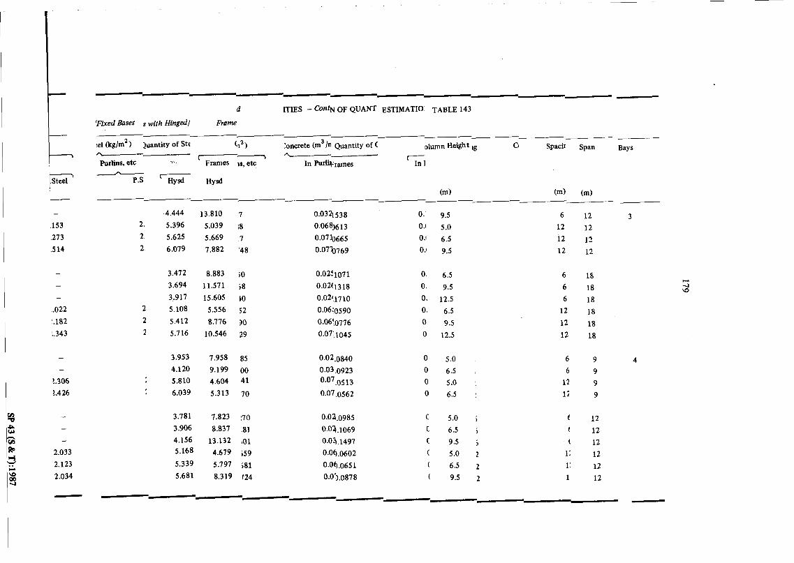
1
1 .Steel
-
153
,273
.5 14
-
-
.022
~182
!.343
-
t.306
1.426
2.033
2.123
2.034
Y_ Ye- -y -- --_
d ITIES - ContN OF QUANT ESTIMATIO: TABLE 143
‘Fixed Bases s with Hinged/ Frame
:el Org/mZ)
--- juantity of Ste Cn2) Ioncrete (m3 /n Quantity of C olumn HeW Ig G Spacir Span Bays
/\ Purlins, etc
(7 /L-------d 11. Frames IS, etc In hWmmes
c- In 1
A P.S ’ HY~ HY~
(m) (m) (m)
2.
2.
2
2
2
2
, 4
4.444
5.396
5.625
6.079
13.810 ,7
5.039 ;8
5.669 7
7.882 ‘48
0.0321538
0.06%613
0.07b665
0.0770769
0. 9.5
0.1 5.0
0.1 6.5
0.1 9.5
6 12 3
12 12
12 12
12 12
3.472 8.883 i0 0.02f1071 0. 6.5 6 lb
3.694 11.571 j8 0.02tl318 0. 9.5 6 18
3.917 15.605 to 0.02‘1710 0. 12.5 6 18
5.108 5.556 52 0.06t0590 0. 6.5 12 18
5.412 8.776 30 0.06!0776 0. 9.5 12 18
5.716 10.546 29 0.07:1045 0 12.5 12 18
3.953 7.958 85 0.02.0840 0 5.0
4.120 9.199 00 0.03.0923 0 6.5
5.810 4.604 41 0.07.0513 0 5.0
6.039 5.313 70 0.07.0562 0 6.5
3.781 7.823 :70 O.Oq.0985 a 5.0
3.906 8.831 !81 0.0’4.1069 C 6.5
4.156 13.132 101 0.01.1497 C 9.5 5.168 4.679 ;59 O.OkO602 C 5.0
5.339 5.797 ;81 O.OkO651 ( 6.5
5.681 8.319 124 0.0:).0878 ( 9.5
6 9
6 9
12 9
, 12 9
i c 12
5 t 12
5 f 12
2 1: 12
2 1: 12
2 1 12
-- --- -- --
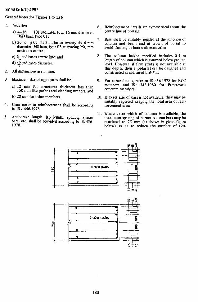
sP43(S&T):1987
General Notes for Figures 1 to 15.6
1.
2.
3
4.
5.
Notation 6.
a) 4-16 101 indicates four 16 mm diameter. HSD bars, type 01;
b) 26-6 $03-250 indicates twenty six 6 mm 7.
diameter, MS bars, type 03 at spacing 250 mm centre-to-centre;
c) $_ indicates centre line; and
d) Cp indicates diameter.
All dimensions are in mm.
8.
Maximum size of aggregates shall be : 9.
a) 12 mm for structures thickness less than 150 mm like purlins and cladding runners, and
b) 20 mm for other members. 10.
Clear cover to reinforcement shall be according to IS : 456-1978
11. Anchorage length, lap length, splicing, spacer bars, etc, shall be provided according to IS:456 1978.
Reinforcement details are symmetrical about the centre line of portals.
Bars shall be suitably joggled at the junction of column and beam and at crown of portal to avoid clashing of bars with each other.
The column height specified includes 0.5 m length of column which is assumed below ground level. However, if firm strata is not available at this depth, then a pedastal can be designed and constructed as indicated in 6.5.4.
For other details, refer to IS:4561978 for RCC members and IS : 1343-1980 for F’restressed concrete members.
If exact size of bars is not available, they may be suitably replaced keeping the total area of rein- forcement same.
Where extra width of column is available, the maximum spacing of corner column bars may be restricted to 75 mm (as shown in given figure below) so as to reduce the number of ties.
7-32 # BARS
b . .
180

-----Z-16103 --~ 1.16102
--17- 8107.
$ECTlON-BB
I’ - 16w1
i
Z-16*03
l-169021 )3-164FOl
t 3-16*01 12%8*06-200
SECTION-AA
A P TOP OF FWNDATION 6600
I DRAWING No.1 (REFER TABLE I )
1inS 1 51641 1636 1 660 I 5 1 1099 1
No. OF BAYS : ONE SPAN SPACING
; :*,“z
COLUMN HEIGHT : i.Gm SUPPORT coNolTlo(I : FIXED FOR AU WIN0 AND
SEISMIC ZONES I MATERIALS:
CONCRETE :un STEEL : Fo MI
- . . .

tFk
Z- 16+04 1-16M3
SECTIDN-AA
1 DRAWING No. 2 (REFER TABLE 2)
i
- No. AN0 SPACING NOTE:
OF PURLINS SLOPE tit Ii2 R
1. ALL DIMENSIONS IN mm PRINCIPAL RAFTER
;;Rf;s SPACING 2. FOR FOUNDATION FORCES REFER TO
ANALYSIS TABLE :2
1 in 3 6680 6320 1417 5 llS1 . 3. DISTANCE OF THE NEAREST PURLIN LUG (K)
lin 4 6695 6305 1063 S 1124 FROM THE a. EXTERNAL COLUMN FACE: 100
6705 6295 850 S 1111 b. RIDGE : 1 in 5 300
No. OF- BAYS : ONE SPAN : 9.0m SPACING : 6.0m COLUMN HEIGHT : 6.5m SUPPORT CONDITION : FIXED
~ FOR ALL WIND AND SEISMIC ZONES 1
MATERIALS: CONCRETE : M 25 STEEL : Fe 415
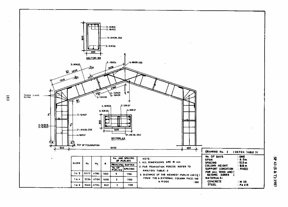
-350
0
,246fOL ~,W6-360
I” c 21-6806-250
44-16~01
2-16@03 2-12*07
2-168021 IL-m01
-----h-6: D6- 250
4 SECTION-AA
A TOP W FOUNDATION -
6bOO
(REFER IABLE 3)
No. AN0 SPACING 0: PURLINS
NOTE : SLOPE Ii1 ii2 R 1. ALL DIMENSIONS ARE H mm
PRINCIPAL RAFTER
p2$:Ns SPACING 2. FOR FOUNDATION FORCES REFER TO
ANALYSIS TABLE :3 lin 3 5217 b734 1400 5 1lSD 3. DISTANCE OF THE NEAREST PURLIN LUG(Q)
lin C 5234 4766 1050 5 1lQt FROM THE a.EXTERNAL COLUMN FACE:100
\ b. RI DCE :36a 1 tin5 I5246I4754I 6401 5 1 1105 I
No. OF BAYS :ONi! SPAN : S.Om SPAC INO : 12.0 m COLUMN HEIOHT :LEm SUPPORT CONDITION : FIXED FOR ALL WIND AND
SEISMIC ZONES I MATERIALS:
CONCRETE : N 2S STEEL : Fa LIS

SECTION- BQ i
2-2vM 2-12,07
2-201021
2-12107
TOP OF FOUNDATION
SECTION-AA
8600
_II
600 1 1 DRAWING No. 4 (REFER TABLE I)
MO. OF BAYS No. AN0 SPACING
: ONE NOTE :
OF PURLINS SPAN : 9.Om
1. ALL DIMENSIONS ARE IN mm SPACING : 12.Om “2 R PRINCIPAL RAFTER COLUMN HEIGHT : 6.5m
No. OF PURLINS SPAC’NG
2. FOR FOUNDATION FORCES REFER TO SUPPORT CON(JlTlON : FIXED ANALYSIS TABLE : 4
6284 1400 5 FOR ALL WIND AN0
1150 _ 3. DISTANCE OF THE NEAREST PURLIN LUG($) SEISMIC ZONES 1
6266 1050 5 1122 FROM THE (1. EXTERNAL COLUMN FACE:100 MATERIALS:
b. RIDGE : 360 CONCRETE : M 25
6254 640 5 1109 STEEL ; Fe 415

t L-1690(
t 2-16403( 12-12607
TOP DF FOUNDATION - 11100
UO SPACING No. AI
OF PURL11
SLOPE II, H2 R PRINCI
~~ P%iiLq
1. ALL DIMENSIONS ARE IN mm IPAL RAFTER
F 2. FOR FOUNDATION F&ES REFER TO
Ns SPACING ANALYSIS TABLE : 5
5217 4764 1900 ! 6 1246 3, DISTANCE OF THE NEAREST PURLIN LUG(P)
, 11.m _, ! _.._ x.__ ,,,_._ i j 6 1219 FROM lHEo.EXTERNAL COLUMN FACE : IGO-
b.RIDCE : 300
1 tin 5 1 S2lSl i75L } 1140 1 6 1 1205 I
DRAWING No. 5 (REFER TA ELE 5)
No. OF BAYS : ONE
SPAN I12.0m SPACING : 6.0m COLUMN HEIGHT : 5.0m SUPPORT CONDITION : FIXED FOR ALL WIND AN0
SEISMIC ZONES I MATERIALS:
CONCRETE : M 25 STEEL : Fe 115 J

L
-350
SECTION-U I
SECTION-AA
TOF OF FOUNOATION 11400 . -__ ~
1 I
I DRAWlNO No. 6 (REFER TABLEBI \
No. AND SPACING No. OF BAYS : ONE
OF PURLlNb NOTE : SPAN I lZ.Om
R 1. ALL DIMENSIONS ARE IN mm
PRINCIPAL RAFTER SPACINO : 6.0m
zRf;6 SPACING 2. FOR FOUNDATION FORCES REFER TO
COLUMN HEIOHT : 6.5m
. ANALYSIS TABLE: 6 SUPPORT CONDITION : FIXED
1900 6 1246 FOR ALL WIND AND
3.DISTANCE OF THE NEAREST PURLINS LUG (Q 1 ~ElSMlC ZONES I
1425 6 12 19
FROM THE a. EXTERNAL COLUMN FACE: 100 M-ATERIALS:
b. RIDGE :300 CONCRETE :M 25
1140 6 1205 STEEL : Fe 415 ._
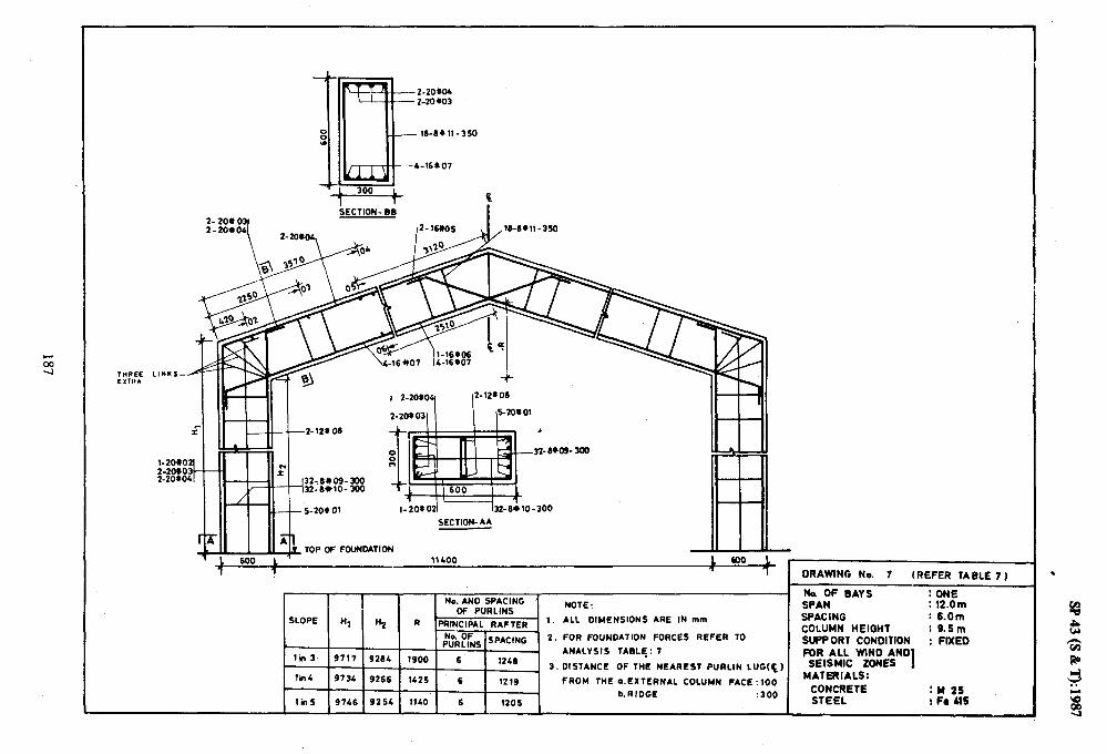
L
SECTION- BB I
l-201021 In-eilo-300
SECTION- AA
TOP OF FOLINDATION -
11400
No. AN0 SPACING ’ OF PURLINS
NOTE :
SLOPE Hl H2 R PRINCIPAL RAFTER 1. ALL DIMENSIONS ARE IN mm
pNuokfks SPACING 2. FUR FOUNDATION FORCES REFER TO
tin 3 9717 ANALYSIS : 7 9264 1900 6 1246
TABLE.
3. DISTANCE OF THE NEAREST PURLIN LUG(Q1
lh4 9734 9266 1425 6 12 19 FROM THE a.EXTERNAL COLUMN FACE ~100
b.RIDGE :300 1hS 9746 9254 1140’ 6 1205
DRAWING No. 7 (REFER TABLE 7 )
Na OF GAYS : ONE SPAN : 12.Om SPACING : S.Om COLUMN HEIGHT : S.Sm SUPP OR1 CONDltlON : FIXED FOR ALL WIND AND
SEISMIC ZONES 1 MATERIALS:
CONCRETE : w 25 STEEL I Fe MI

SECTION-AA
TOP OF FOUNDATION -
----+- IDR*WIHO 8 (REFER TABLE 8 )
. No. OF BAYS : ONE No. AND SPACING SPAN : 12.0m OF PURLINS
NOTE:
SLOPE Ii, . 1. ALL DIMENSIONS ARE IN mm SPACINO : 12.0m HZ R PRINCIPAL RAFTER
2. FOR FOUNDATION FORCES REFER TO COLUMN HEIGHT : 5.0m
i,$Rp&s SPACING SUPPORT CONDITION : FIXED ANALYSIS TABLE: 6 AND
lin 3 5217 4764 1900 FOR ALL WIND
6 1236 3. DISTANCE OF THE NEAREST PURLIN LUG (Q)
SEISMIC 2DNES 1
lin 4 5234 4766 1425 6 MATERIALS:
1207 FROM THE ,,.EXTERNAL COLUMN FACE : 100
360 CONCRETE :
b. RIDGE M 25 :
1 in 5 5246 4754 1140 6 1¶93 STEEL : Fe 415

SECTION- 88
l
21.8+09-300’ I : :1’ 21-8~09-300
2l_OClO-300
S-201 01 121_ 6; 10-300
SECTION-AA
A' TG TOP OF FOUNDATION 11400
- L
DRAWING No. 9 (REFER TABLE 9 1
k OF BAYS : ONE No. AND SPACING NOTE : SPAN : 12.0 m
OF PURLINS . 1, ALL OIMENSIONS ARE IN mm SPACING : 12.0m SLOPE H, H2 R PRINCIPAL RAFTER
- 2. FOR FOUNDATION FORCES REFER TO COLUMN HEIGHT : 6.5m
$;Ry;Ns SPACING SUPPORT CONDITION ANALYSIS TABLE : 9
: FIXED FOft ALL WIND AND
1 in 3 6717 6284 1900 6 1236 3. DISTANCE OF THE NEAREST PIJRLIN LUG (0 SEISMIC ZONES I
lin 4 6734 6266 1425 6 1207 FROM THE aEXTERNAL COLUMN FACE:100 MATERIALS:
b.RIDGE : 360 CONCRETE :w 25
lin 5 6746 6254 lli0 6 1193 STEEL : Fe LtS

2-32*01
I I
2-1z*m
,L-32*01
T OP OF FOUNDATION II I
lWO0 1 600
1
DRAWING No. 10 ( REFER TABLE 10)
No. OF BAYS : ONE No. AND SPACING NOTE: SPAN : 12.0m
OF PURLINS
SLOPE Hl n2 R SPACING : 12.0m
PRINCIPAL RAFTER 1. ALL DIMENSIONS ARE IN mm
COLUMN HEl&T : O.Sm No. OF * PURLINS SPACING
2.FOR FOUNOATION FORCES REFER TO SUPPORT CONDITION : FIXED FOR ALL WIND AND
1 in 3 9717 926L 1900 6 . ANALYSIS TABLE: 10
1236 SEISMIC ZONES . 3.OISTANCE OF THE NEAREST PURLIN LUG(C)
I
lin 4 9774 9266 lL25 6 MATERIALS:
1207 FROM THE a. EXTERNAL COLUMN FACE: 100 CONCRETE :360
:u 25
1 in S 97A6 9254 1140 6 1193 b.RIOGE STEEL : Fe 415
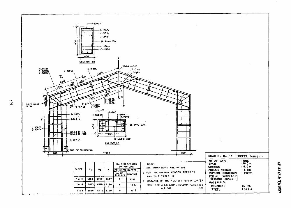
-36-.3tll-i
SECTION- 6;
!60
c
I ,36- IVlL- 260
I-l‘V1”
I
J!! ,)--#j- 2l-ev12-320
2l-)b 12 - 320 2140 13 - 320
s-20*0, i21_rJbT3-320
SECTION-AA
j_
.'
TOP OF FOUNDATION
800 L _____ 112"" L 0"" i
1 1 1 1 DRAWING No. 11 I REFER TABLE 11)
No. AND SPACING NOTE: OF PURLINS
SLOPE Ml 1. ALL DIMENSIONS ARE IN mm
“2 R PRINCIP*L RAFTER
pNuok& SPACING ’ 2. FOR FOUNDATION FORCES REFER TO
ANALYSIS TABLE :ll lin 3 6789 6212 2867 8 1358
3. DISTANCE OF THE NEAREST PURLIN LUG(c)
lin 4 6813 6180 2150 8 1327 FROM THE aEXTERNAL COLUMN FACE : 100
b. RIDGE : 300 lin 5 6828 6172 1720 e 1312
ND. OF BAYS : ONE SPAN : 18.Om SPACING : 6.0m COLUMN HEIGHT : 6.6m SUPPORT CONDITION : FIXED FOR ALL WIND AN
SEISMIC ZONES “I MATERIALS:
CONCRETE :M 25 STEEL :FeblS

I VI I
._ . . ,I: ._ _. . . . . .- _
I *- 0
w 0

iEClION- Be
260
io-6w-2-320 a :wl
LO-9*12-320
l-2bod
$
SE :c1iON-AA
‘Leo0 L’ 17200
1 DRAWING No. 13 (REFER TABLE 13)
No. OF BAYS : ONE No. AND SPACING NOTE, SPAN :l&Om
OF PURLINS
SLOPE Hl R2 R PRINCIPAL RAFTER a 1. ALL DIMENSIONS ARE IN mm SPACING :6.Om
COLUMN HEIGHT : 12.5 m No. OF PURLINS SPAc’NG
2. FOR FOUNDATION FORCES REFER TO SUPPORT CONOlTlON : FIXED ANALYSIS TABLE : 13 FDR ALL WIND AND
1 in 3 12709 12212 2667 6 1356 SEISMIC ZONES 3. DISTANCE OF THE NEAREST PURLIN LUG(P)
1 MATERIALS :
1 in 4 12913 12166 2150 6 1327 FROM THE aEXTERNAL COLUMN FACE:100 CONCRETE :M 26 ;300 : Fa 415 1 in 5 12828 12172 1720 e 1312
b. RI OGE STEEL

i.EC~lOlu. 3-16M
2-:5*03, / !=“r-,,_,,,,,
s-25*01 -l&ee13-
SECTION-AA
TOP OF FOUNOATlON
6
,360
NaAND SPACING NOTE : OF PURLINS
SLOPE Ii, “2 R PRINCIPAL RAFTER . 1. ALL DIMENSIONS ARE IN mm
No. OF P”RLINS]SPACING
2. FOR FOUNDAlION FORCES REFER TO
ANALYSIS TABLE : 10 1 in 3 6769 6212 2667 6 1350
3 .DISTANCE OF THE NEAREST PyRLlN LUG (cl
FROM THE a. EXTERNAL COLUMN FACE : 100
b.RIOGE : 360
DRAWING No. 14 (REFER IABLE IS)
No. OF BAYS : ONE SPAN :lB.Om SPACING : 12.0 m COLUMN HEIGHT :6.5m SliPPORT CONDITION : FIXED FOR ALL WIND AN0
SEISMIC ZONES I MATERIALS:
CONCRETE :M 25
STEEL : Fe 415
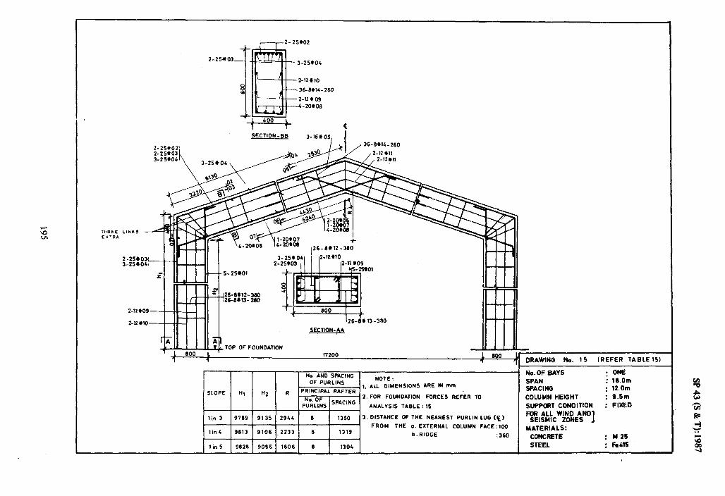
SllY : stn :
am4 : IJag. : ~0’21 : ~0’91 :
3NO :
13316 313mNO3
:slvlY31v
I SW02 31ns13s
ONV aNlM 1lV M NOlllaN03 1llOddf
llml3H Nwnlc 9Nl3Vc
NVd SAW do ‘C
(S1318V1 M333Y) Sl ‘ON BNIMVC
TOE1 a 9061 9906 87.96 s U! 1
39t: 3oaIu ‘9 blbl a EfZZ’ 9016 EL96 ?U!l 001:32Vd NWtll03 lVNL131X3 ‘0 3Hl WOYd
(3, 3fll NIlMIld lS3UV3N 3Hl K) 35NVlSIO ‘E osti 0 ‘176Z , SE16 6916 c U!L I
Sl : 31611 SISAlVNV 9NlJVdS SN’lUnd
01 Y3d3Y S3JYOd NOIlVONllOd UOd ‘Z JO ‘ON
Y311VY lVdl3NIYd LI ZH LH 3dO7S
u)W N, 3MV SNOISN3WIa nV ‘1 : 310N
SNIlYnd 40 3Nl3VdS ONV ‘ON
NOIlVONflOllr)O d01
I 'SUCSL-E sB’Nal133s

l-32*02
k:m I-
r-,--2- 32903
2-32+04
2-na10
36-69X-
2-12 909
s-209 00
260
&ClION- B@ 3-16905, kI ,36-6?14-260
SECTION-A&
TOP OF FOUNDATION
i7200 , 1 DRAWING No. 16 (REFER TABLE 161
Na AN0 SPACING No.OF BAYS : ONE
OF PURLINS NOTE : SPAN : 18.Om
1. ALL DIMENSIONS ARE IN mm SPACING SLOPE tl, H2 R PRINCIPAL RAFTER
: 12.0m
pFi;;s SPACING - 2.FOR FOUNDATION FORCES REFER TO COLUMN HEIGHT : 12.5m
ANALYSIS TABLE : 16 SUPPORT CONDITION : FIXED
lin 3 12799 12212 2667 6 1350 FOR ALL WIND AND
3 .OISTANCE OF THE NEAREST PURLIN LUG (c, SEISMIC ZONES I
lin L 12613 12166 2lS0 6 1319 FROM THE a.EXTERNAL COLUMN FACE :100 MATERIALS:
b.RIOGE : 360 CONCRETE : M25
1 in S 12626 12172 1720 3 idi STEEL :_. Fe415

3-25’cO3-
2-16X10
59-Lwl3-
2-16+09 a-25+08
SECTION-BP
2-‘6*oSI \. I ,59-8*13~210
II SECTION-AA
TOP OF FOUNDATION 23000
2%6#12-36d
t 2sw12- 360
SLOPE “I
1 in 3
- 9861
1 in L 9691 __
9910 tin 5
-
“2
f
, 1000 1 7 7
I DRAWING No. 17 [REFER TABLE 17)
No.OF GAYS : ONE
3633 1 11 1 1276 I 3.DISTANCE OF THE NEAREST PURLIN LUG(c)
FROM THE’a. EXTERNAL COLUMN FACE : 100 :::‘,/I - b.RIDGE : 300
SPAN : 2L.Om
SPACING : 6.0m
COLUMN HEIGHT : 6.5m
SUPPORT CONDITION : FIXED FOR ALL WIND AND
SEISMIC ZONES 1 MATERIALS:
CONCRETE : M25
STEEL : Fe416

.3-25#03 ---L-25*02
Z-16* 09
59-6X12-210
2-KY08 3-20X07
SECTION.iB 2-16+07
,59-6*12-210
34-Wll- 360 34-6+11- 360 34- se11 - 3Bo
i
SECTION-AA
TOP OF FOUNDATION I I 1000 L -’ 23000
? 1 1 1000
1
No. AN0 SPACING OF PURLINS
SLOPE Ml “2 R PRINCIPAL RAFTER
pN;I;(fks SPACING
1 in 3 12661 12140 3633 11 1276
I in 4 12891 12110 2075 10 1307
lin 5 12910. 12090 2300 10 1372
-
1.
2.
3.
NOTE : ALL DIMENSIONS ARE IN mm
FOR FOUNDATION FORCES REFER TO
ANALYSIS TABLE: 13
DISTANCE OF THE NEAREST PURLIN LUG (PI
FROM THE a. EXTERNAL COLUMN FACE :lOO
b. RIDGE : 300
DRAWING No. 18 (REFER TABLE 18)
No.OF GAYS : ONE
SPAN : 24.Om
SPACING ’ : 8.0m
COLUMN HEIGHT : 12.Sm
SUPPORT CONMTION : FIXED FOR ALL WIND AND
SEISMIC ZONES I MATEMALS:
CONCRETE : M25 STEEL : Fe415

3-32X04
Z-16*09 4-20#00
SECTION-BB 2-25Y 0
7 I I ,5.3-6*14-210
25-8*13- 360
SECTION-AA
DRAWING No. 19 (REFER TABLE 19)
No. AND SPACING No.OF BAYS : ONE
OF PURLINS NOTE : SPAN : 24.0m
SLOPE H, Hz R PRINCIPAL R*FTER 1. ALL DIMENSIONS ARE IN mm SPACING : 12.0m
p;$;s SPACING Z.FOR FOUNDATION FORCES REFER TO COLUMN HEIGHT : 9.5m
. ANALYSIS TABLE: 19 SUPPORT CONDITION : FIXED
lin 3 9661 9063 3910 11 12 72 FOR ALL WIND AND
3.DISTANCE OF THE NEAREST PURLIN LUG (Q, SEISMIC ZONES 1 lh 4 9691 9026 2958 10 1360
FROM THE o. EXTERNAL COLUMN FACE : 100 MATERIALS: b.RIDGE : 360 CONCRETE : M25
1 in 5 ‘9910 9004 2’366 10 1365 STEEL : Fe b15

SECTION-BB
,S6-6113- 210
I-- ;6--%tOl rt-t
-33-6112-360
l
SECTION-AA
TOP OF FOUNOATION
1000 L 1 23000 I 1000 1 7
-
I DRAWING No. 20 (REFER TABLE 20)
No. AN0 SPACING . No.OF BAYS : ONE
NOTE : OF PURLINS SPAN : 24.Om
1. ALL DIMENSIONS ARE IN mm SLOPE Hl Hz I4 PRINCIPAL RAFTER
SPACING : 12.0m
pzi& SPACING 2. FOR FOUNDATION FORCES REFER TO COLUMN HEIGHT : 12.5m
ANALYSIS TABLE : 20 SUPPORT CONDITION : FIXED FOR ALL WlND AND
lin 3 12661 12lLO 3633 11 1272 3. DISTANCE OF THE NEAREST PURLIN LUG(E) SEISMIC ZONES I MATERIALS:
1 in 4 12691 12 110 2675 10 1360 FROM THE a. EXTERNAL COLUMN FACE: 100
b.RIOGE : 360 CONCRETE : M25
lin 5 12910 12090 2300 10 1365 STEEL : Fe415

N 0
L
__ --__
I 1 B
SECTION-BB - .CL~C 1
74-W13-210
/, 2-l6,11
i ,2-161)ll
- 2S-8W12-380
-2%8W2- 380
~‘--“- +! Lo! I@ TOP 0FFO"NOATlON
SECTION-AA
I
2gooo , too0 1 1 7 7 1 .
SLOPE
lin 3
1 in 1.
1 I” 5
DRAWING No. 21 (REFER lAGLE.ZI)
No.OF GAYS : ONE No AND SPACING NOTE. SPAN : 30.0m
OF PURLINS 1. ALL DIMENSIONS ARE IN mm SPACING : 6.0m
Hl “2 R . PRINCIPAL RAFTER 2. FOR FOUNDATION FORCES REFER TO COLUMN HEIGHT : 9.5-m
::,,“:,, ISPACING SUPPORT CONDITION : FIXED ANALYSIS TABLE: 21
FOR ALL WIND AND 3. DISTANCE OF THE NEAREST PURLIN LUG(c) SEISMIC ZONES I
FROM THE a.EXTERNAL COLUMN FACE : 100 MATERIALS:
CONCRETE : M26 STEEL : Fe415 .-
I I I I I I
,

3-32XOL
Z-161(09 3-2W08
SECTION -88
33-8ei2-380
SECTION-AA
I 1 I I 1 No. AND SPACING 1
/sLopEI H, / H2 1 R wj:, 1 in 3 12861 12063 1910 13 1328 3.
lin L 12891 12028 3707 13 1298
1 in 5 12910 1200* 2906 12 1100
NOTE :
ALL DIMENSIONS ARE IN mm
FOR FOUNDATION FORCES REFER TO
ANALYSIS TABLE : 22 DISTANCE OF THE NEAREST PURLIN LUG(Q)
FROM THEaEXTERNAL COLUMN FACE : 100
b. RIDGE : 300
1 DRAWING No 22 (REFER TABLE 22)
No.OF GAY S : ONE
SPAN : 3QGm
SPAClNG : 6.0 In COLUMN HEIGHT : 12.5m
SUPPORT CONDITK)N : FIXED FOR ALL WIND AND
SEISMIC ZONES
MATERIALS: CONCRETE : M25 STEEL : Fe b15

417=zd : 1331s szw : 313XJN03
:slvlY3lvw S3NOZ 3lWSl3S
aNV aNlM lit’ tlOd (13x14 : NOlllaN03 1YOddllS IuS. : lH013H NWfll03 ~0~21 : ONl3VdS
WO’OE : NVdS
3NO : SAVB 40-N
09c: 3z)ait( q
001:33V’d NWnl03 lVNt131X3 0 3Hl WOtld
S6El 21 9862 7006 0166 s U!L
ELZL EL LOLE 8206 1686 7 U!I
In1 NIlkInd lS3UV3N 3Hl 40 33NVlSIa’E EZEL EL 0167 E906 1986 E u!i
EZ : 31811 SISAlVNb
01 t(333tl S3JtlOd NOIlVONIIOd tlad ‘Z . 3NIJVdS ‘“:;“o”,”
M31jVM 1VdlSNltJd tl IH ‘H 3dOlS
“JU N, 3tlV SNOISN3Wla 1lV ‘1 SNIlHJnd JO
:310N ‘DNlJVdS ONV “‘N
L c l_ 0001 1 00062 L 1 0001 1 L
II
NOllVONflOj 30 dO’F[174
UI

S-32W33-
t-4-32*04
-l-32+02
-2-16#10
- 90-8113 -170
- 2-16SO9 -4-32: 06
II I I
33-6012-380
----
SECTION-AA
TOP OF FOUNDATION
29000
-T-r SLOPE Ii1 H2 R
4633
3625
2900
. 1000 . 7 I -
No. AND SPACING OF PURLINS
NCTE:
1 ALL DIMENSIONS ARE IN mm PRINCIPAL RAFTER
2. FOR FOUNDATION FORCES REFER TO
ANALYSIS TABLE: 24
3. DISTANCE OF THE NEAREST PURLIN LUG(Q)
FRO” THE a. EXTERNAL COLUMN FACE: 100
b. RIDGE : 360
1 DRAWING No. 24 (REFER TABLE 20
No.OF GAYS : -ONE
SPAN : 30.0m
SPACING : 12.0m
COLUMN HEIGHT : 12.5m
SUPPORT CONDITION : FIXED FOR AU WIND AND
SEISMIC ZONES 1 MATERIALS:
CONCRETE : M25 STEEL : Fe415

-17-64C&270
SECTION-BB SECTION-CC
2-16tO3 2-16403
I-lCe0 2-1610
I I--ttt3-“01
11-16802
SECTKIN-AA
-- I-
2-w 03
jl!y -‘r 400 1
25-6607-200
fi -z;l
SECTION-DD
TdP OF FCUNOATI0N 6600 LOO
DRAWING No. 25 (REFER TABLE 25)
Ic
- No. OF BAYS : TWO
LCING OF PURLINS NOTE : SPAN : 9.0m
1 Ai 1, DIMENSIONS ARE IN mm SPACING : 6.0m
-“*---‘-*’ FORCES REFER 10 COLUMN HEIGHT : 5.0m
“C SUPPORT CONDITION : FIXED
I I I I I NaANo SPA
SLOPE II, li2 R EXTERIOR RAFTER INTERIOR RAF
,,,,F$S SPACING p;;;.;;s SPACING ___
2.FDR rwmmr~u~~
ANALYSIS TABLE : I, lh 3 5144 4656 1433 5 1139 4 1361 3.DISTANCE DF THE NEAREST PURLIN LVC (c)
FOR AU WIND AND
I FRC,” T”E a. EX1FDLI.I Pfil ,,“.I PIPF tnn I SEISMIC ZONES I . _ . . . . I_ “____... . ___ .“”
I. ndGE : 300 MATERIALS:
c.VALLEY : 300 CONCRETE : M25
1 1 in 5 I5164 14636 1 660 1 5 1 IO& 1 4 1 1330 1 STEEL : Fe 415
1 lk4 jSlS6 I4644 11075 1 5 1 1111 1 4 1 1346 ! * Ll”
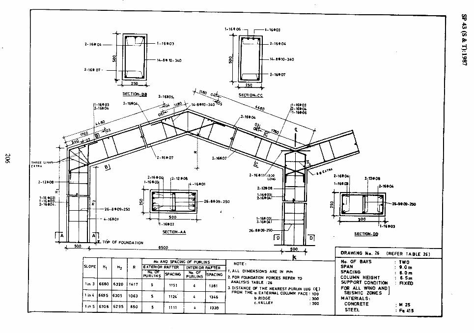
902
!?2
w
N-
i
1
L86
I $1
‘B
S)
Et
dS
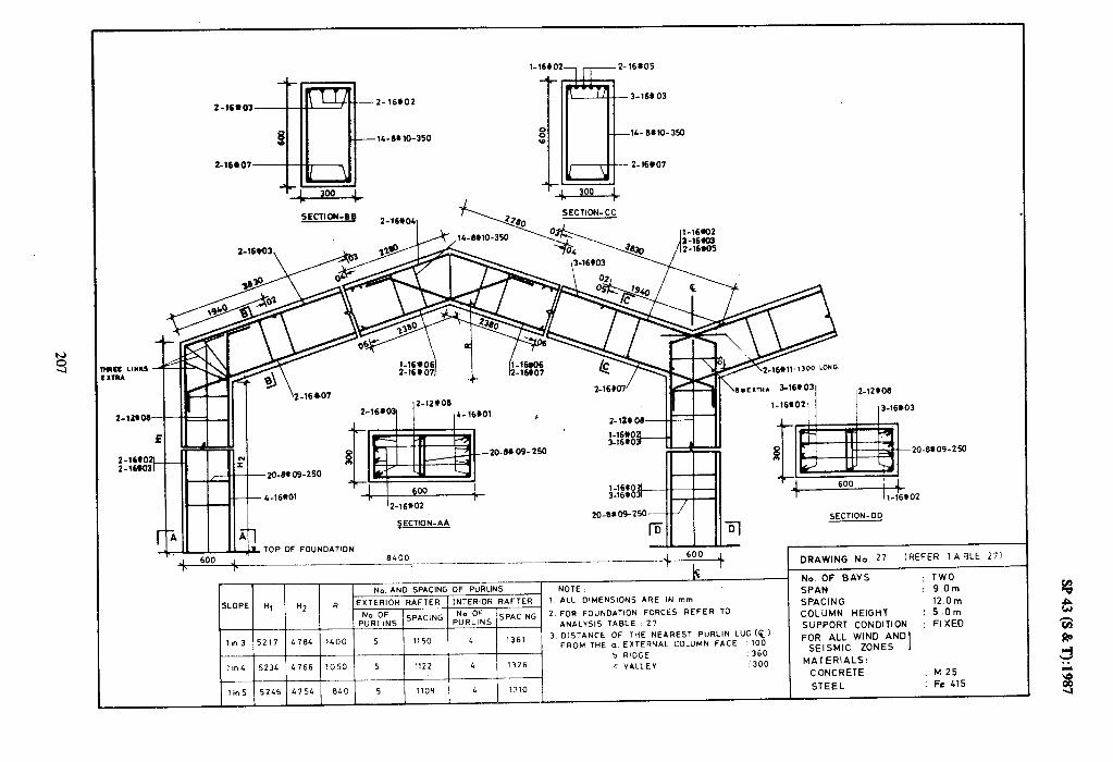
l-16*02, r-Z-16*05
2-xeo3 Z- 16602
14-6*10-350
SECTION-B8 --v?.¶o , SECTIDN-CC 2;16.041
t
3-16s 03
SECTION-AA
\ ~.~CITRA %16*D31 2-12*06
l-16*02\ ( ,3-16L03
SECTION-DO
Til
-m 09 -250
No AND SPACING OF PURUNS NOTE
SLOPE Hl H2 R EXTERIOR RAFTER INTERIOR RAFTER 1 ALL DIMENSIONS ARE IN mm
2 FOR FOUNDATION FORCES REFER TO ,“,“,&S SPAC’NG &::NS SPAC’NG. ANALYSIS TABLE. 27
4704 lLO0 S 1150 L ?361 3 DISTANCE OF THE NEAREST PURLIN LUG ($1
111-13 5217 FROM THE o EXTERNAL COLUMN FACE 100 b RIDGE : 360
IIll 5234 4766 1050 5 1?22 4 1326 c VALLEY : 300
-.
1 in 5 5246 415L 640 5 1109 4 1310
DRAWING No. 27 (REFER 1 ABLE 27)
No. OF BAYS : TWO
SPAN : 9.0m
SPACING lZ.Om
COLUMN HEIGHT : 5.0m
SUPPORT CONDITION : FIXED
FOR ALL WIND AND SEISMIC ZONES I
MATERIALS:
CONCRETE ; hi25
STEEL : F,? 415

2-16603
2- 16.07
-2-16602
-11-6#10_3!jO
3- 16+03
2-16*07
:E LIw RA -16# 1, - ,300 LONG
ZlbO6
!-lZ’O6 _ .____
2-16% 2- 16‘
SECTION- AA SECTION-00
TOP OF FOUNDATION
DRAWING No. 28 (REFER TABLE 28)
No. AN0 SPACING OF PURLINS NOTE : No. OF BAYS : TWO
SLOPE H, H2 R EXTERIOR RAFTER ‘NTER’oR RAFTER_ 1. ALL DIMENSIONS ARE IN mm SPAN : 9.0m
pv”;;& SPACING $& S!‘ACING SPACING : M.Om
2.FOR FOUNDATION FORCES REFER TO COLUMN HEIGHT : 6.5m ANALYSIS TABLE : 28
!,n3 6717 626L 1400 5 1150 SUPPORT CONDITION
I 1361 : FIXED
3.DISTANCE OF THE NEAREST PURLIN LUC (g) FOR ALL WIND AND . FROM THE o.EXTERNAL COLUMN FACE: 100 SEISMIC ZONES 1 I,“5 6734 6266 1050 5 1122 L 1326 b. RIDGE : 360 MATERIALS:
J
1 / I I 1 I I c. VALLEY :300 CONCRETE
lin5 6746 6251 B&O 5 1169 L 1310 : M25
STEEL : Fe US

c--l-l6XO5
2;16*03 Z-16#02
B ,
H 1&8*10-350
Z-16*07
300
2-16902-
SECTION-BB 2-16@cy
2- 166 03
2-16(;07
r I- 12-16?02
I II I Ii I SECTION-DO
J 600 r . DRAWING No. 29 (REFER TABLE 29)
k No. AND sp*tlNG OF PURLINS
No. OF BAYS ; TWO _ NOTE: SPAN : 12.0m
SLOPE II, Ii2 R EXTERIOR RAFTER INTERIOR RAFTER ,.ALL DIMENSIONS ARE IN mm SPACI NO : 6.0m
Pk~:NS SPAC’NG P%LtlFNS SPAC’NG 2.FOR FOUNDATION FORCES REFER TO COLUMN HEIGHT : 5.0m ANALV5,S ,ABLE : 2S
SUPPORT CONDITION : FIXED
linl 5217 4764 1900 6 1248 6 1146 3 .OISTANCE OF THE NEAREST PURLIN LUG (‘$1 FOR ALL WIND AND
FROM THE 0. EXTERNAL COLUMN FACE ! 100 SEISMIC ZONES I
I’m4 5234 C766 IL25 6 1219 5 1396 b. RIDGE : 300 MATERIALS i CONCRETE : M25
6 1205 5 1360 c.VALLEV : 300
tin5 5246 4754 1140 STEEL : Fe 415

2-16603
Z-16*07
---Z-16,02
- 18-8#10-350
Z-16lIO5
,l-16WO2
--3-16*03
- lb8#10-350
- 2-16W7
16911 -lx)0 LOW
(r No. AND SPACING OF PURLINS
NOTE : SLOPE Ii1 H2 R EXTERIOR RAFTER INTERIOR RAFTER
1. ALL DI MEWIONS ARE IN mm
$;;;5 SPACING ,,“,“,f,‘, SPACING 2. FOR FOUNDATION FORCES REFER TO
lin3 6717 6284 1900 6 !248 6 1145 ANALYSIS TABLE : 30
P.DISTANCE OF THE NEAREST PURLIN LUG (Q) lin4 6734 6266 14 25 6 1219 S 1396 FROM THE a. EXTERNAL COLUMN FACE : 100
b. RIDGE : 300
1 in5 6746 6254 1140 6 1205 5 1380 c.VALLEV : 300
SECTION-AA aO-RLm-‘l)
SECTION- 00
J 600 r I- I DRAWING No. 30 (REFER TABLE 30)
No. OF BAYS : TWO SPAN : 12.Om SPACING : 6.Om COLUMN HEIGHT : 6.5m SUPPORT CONDITION ; FIXED FOR ALL WIND AND
SEISMIC ZONES MATERIALS:
CONCRETE ; M25 STEEL : Fe (15

L
,----l-16*03
3-16#03 2- lC+OC
16-8~13-350
2-16809
2- 16tO6
t
8 w
t
3-16804
Y)-m13-350
2-16eO9
SECTION- AA
TO’P OF FOUNDATION
J 600 .I 11400 r r
-_.-
No.AND S%NG OF PURLINS NOTE :
SLOPE H, H2 R EXTERIOR RAFTER INTERIOR RAFTER 1 ALL DIMENSIONS ARE IN mm
ppRL$ SPACING prRL$ SPACING 2 FOR FOUNDATION FORCES REFER TO
lin3 9717 9264 1900 6 ANALYSIS TABLE 124.9 6 1145 3,
3 DlSTANCE OF THE NEAREST PURL!N LUG (‘%I
1lnL 9734 9266 6 12 19 5 1396 FROM :HE a EXTERNAL COLUMN FACE :I00
1425 b RIDGE .300
c VALLEY : 300
lin5 97L6 9154 1140 6 ?205 T !380
, h-16-3
SECTION-DO
-6+12-350
DRAWING No. 31 (REFER TABLE 31)
No. OF BAYS : TWO SPAN : 12.0m SPACING : 6.0m COLUMN HEIGHT : 9.5m SUPPORT CONDITION : FIXED FOR ALL WIND AND
SEISMIC ZONES I MATERIALS:
CONCRETE : I.425 STEEL : Fe 415

2-16906 -
SECTION-BE 2-16905,
-4 a SECTION-AA
TOP OF FOUNDATION 1 J l1400
P _I 600 +
. No. AND SPACING OF PURLIN
SLOPE H, H2 R EXTERIOR RAFTER INTERIOR RAFTER
p$L$ /SPACING ,,“;;i$ /SPACING
I I
SECTION-DO
q
- I
NOTE :
1. ALL DIMENSIONS ARE IN mm
Z.FOR FOUNDATION FORCES REFER TO
ANALYSIS TABLE : 32
3. DISTANCE OF THE NEAREST PURLIN LUG (Q,
FRO,., THE a.EXTERNAL COLUMN FACE: 100
b. RIDGE : 360
C VALLEY : 300
DRAWING No. 32 [REFER TABLE 32)
No. OF BAYS : TWO SPAN : 12.0m SPACING : 12. Om COLUMN HEIGHT : S.Om SUPPORT CONDITION : FIXED FOR ALL WIND AND
SEISMIC ZONES 1 MATERIALS:
CONCRETE : M 25 STEEL : h 615

4 f
-- 2-20103
3-20402
iz --lo-Pal&350
3-166 10
SECTIct4-BB
2-20606 3-20905
2-2otO6
16OtlL-350
JE3-3-16’10 *A SECTION-CC
I lrni I _ ._-._
3_2M02,
SECTION-DO SECTION-AA
I DRAWING No. 33 (REFER TABLE 33)
1. ALL DIMENSIONS ARE IN mm
2.FOR FOUNDATION FORCES REFER TO
ANAVSIS TABLE : 33
3,DISTANCE OF THE NEAREST PURLIN LUG (cl
FROM THE a. EXTERNAL COLUMN FACE : 100
COLUMN HEIGHT SUPPORT CONDITION FOR AU WIND AND
SE1 SMIC ZONES
c.VALLEV
TWO lt.Om 12.Om 6.Sm FIXED
M 25 Fe 415

SECTION-BB
TdP OF FOUNOAlIOh
+I 600 J 11400 600
rkr No. AND SPACING OF PURLINS - NCTE :
SLOPE Ii, H2 R EXTERIOR RAFTER 1 INTERIOR RAFTER N OF
l.ALL DIMENSIONS ARE IN mm
PUtLlNS SP*CING p:i:;S SPACING 2.FOR FOUNDATION FORCES REFER TO 4
lin3 9’117 9284 1900 6 1236 6 ANAVSIS TABLE : 34
1133 3. DISTANCE OF THE NEAREST PURLIN LUG &,
1 in4 9736 9266 1425 6 1207 5 1361 FROM THE a. EXTERNAL COLUMN FACE : 100
b.RIDGE :360 c .VALLEV : 300
lin5 19766 13254 1 1140 1 6 I 1193 I 5 I 1365 I
I DRAWING No. 34 (REFER TABLE 34 1
No. OF BAYS : TWO SPAN : 12.0m
SPACING : 12.0m
COLUMN HEIGHT : 9.5m
SUPPORT CONDITION : FIXED
FOR ALL WIND AND
SEISMIC ZONES I
MATERIALS:
CONCRETE : M25
STEEL : Fe 415
_-

2-2oto2 3-2otO4
368t15-260
2-11 #ll
3-1006
L-ll!_l I II I
I ” . ..M
_ _ _. . _. . _ . 17200 , 800
r Ir
-(#13-320
DRAWING No 35 (REFER TABLE 35)
,E
No. AND SPACING OF PURLINS NOTE :
SLOP; H1 H2 R EXTERIOR RAFTER INTERIOR RAFTER 1. ALL DIMENSIONS ARE IN mm
pNuifiLs ISPACING pNu+LqLs 1 SPACING 2. FOR FOUNDATION FORCES REFER TO
I I ANALYSIS TABLE: 35
No. OF BAYS : TWO
SPAN : 18.Om SPACING : 6.0m
COLUMN WEIGHT : 6.5m SUPPORT CONDITlDh : FIXED
3. DISTANCE OF THE NEAREST PURLIN LUG cc)
FROM THE o.EXTERNAL COLUMN FACE : 100 b. RIDGE

SECTION-BB
.oms-390
DRAWING No 36 (RiFER TABLE 36)
1. ALL DIMENSIONS ARE IN mm
i’.FOR FOUNDATION FORCES REFER TO
ANALYSIS TABLE : 36
3.DISTANCE BF THE NEAREST PURLIN LUG cc,
FRBH THE o.EXTERNAL COLUMN FACE : 100
b. RIDGE :3OO
E. VALLEY :3OO
No. OF BAYS SPAN
: TWO : 19.Om
~ >PAClNG * 6.0m COLUMN HEIGHT I 9.Sm SUPPORT CONDITION : FIXED FOR AU WIND AND
SEISMIC ZONES I MATERIALS:
CONCRETE : w25 STEEL :Fa41s

L
Z-25603 Z-25003
2 25#02
2-n t 11
2-u t10
J-16609 36-B(t16-260
SECTION-B8
Z-25.903, \._
4-25801 I 800 1 lz-2S.02
r
SECTION-AA
J-- - -- 17200 J 600 I= r
Ic a-
No. AND SPACING OF PURLINS NOTE :
SLOPE Hl n2 R EXTERIOR RAFTER INTERIOR RAFTER 1. ALL DIMENSIONS ARE IN mm
&& ISPACING &;;s SPAC,NG 2.FOR FOUNDATION FORCES REFER TD
1 r I ANALYSIS TABLE: 37
1 h3 72799 12212 2667 9 1356 8 1270 3, DISTANCE OF THE NEAREST PURLIN LUG (c)
. FROM THE aEXTERNAL COLUMN FACE : 100
lb,4 12613 1206 2lSO 6 1327 6 1240 b.RIDGE : 300
c.VALLEY : 300
(in5 12629 12172 1720 6 1312 8 122s
.6614-360
SECTION-DO
DRAWING No 37 (RiFER TABLE 37)
Na OF GAYS : TWO SPAN : 18.Om SPACING : 6.Om COLUMN HEIGHT : 12.5m SUPPORT CONDITION : FIXED FOR AU WIND AND
SEISMIC ZONES I
MATERIALS: CONCRETE : M25 STEEL : Fe L15

L
SECTION-BB
SECTION-AA
10-p OF FOLINOATION
I llB-erlr:3Bo
SECTION- DO
No. AND SPACING OF PURLINS NOTE: SLOPE Ii, H2 R EXTERIOR RAFTER INTERIOR RAFTER
puck,;; SPACING
1. ALL DIMEN!WNS ARE IN mm
p;;LT;S SPACING Z.FOR FOUNDATION FORCES REFER TO
ANALYSIS TABLE : 30 1 in3 6709 6212 2667 8 1350 8 1206 3. DISTANCE OF THE NEAREST PURLIN LUG. (6)
’ lid 6813 6lBB 2150 a 1319 8 FROM TKE 1254
a. EXTERNAL COLUMN FACE : 100
b. RIDGE : 360
lin5 6828 6172 1720 8 1304 B 1239 c. VALLEY : sso I I I I I I I I
DRAWING No 38 (AEFER TAGIf 38)
No. OF BAYS : TWO SPAN : thorn SPACING COLUMN HEIGHT
; y-g SUPPORT CONDITION : FiXED FOR AU WIND AND
SEISMIC ZONES I MATERIALS:
CONCRETE : M2S STEEL : h us

z-u*12 3-2Dwo
I’-.lzm Y
‘%:;‘::;‘:yffi ,2_~,c_r___,
3-25803-- . i I t*“’ .
SECTION-AA
OP OF FOUNDATION
c-25102 3-251rD6
2-25103
2-d * 12
2-124811 2-28.10
36-WI&k260
SECTION-BB
-Ylb- MO
No. AND SPACING OF PURLINS NOTE : SLOPE H, H2 R EXTERIOR RAFTER INTERiOR RAFTER
p$LqLs ]SPACING
1. ALL DIMENSIONS ARE IN mm
p;;;;s SPACING 2 FOR FOUNDATION FORCES REFER TO
I I I ANAYSIS TABLE 39
3.DISTANCE OF THE NEAREST PURLlN LUG (‘&)
FROM THE (1 EXTERhAL COLUMN FACE: 100
b RIDGE : 360
DRAWING No 39 (REFER TABLE 39)
No. OF BAYS : TWO SPAN : 19.Om SPACING : 12.Om COLUMN HEIGHT : 9.5m SUPPORT CONDITION : FIXED FOR ALL WIND AND
SEISMIC ZONES I MATERIALS:
CONCRETE : M25 STEEL : Fe Cl5

s1t %I : 1332s CEZL 8 20EL 8 OZ‘L ZLLZL 8Z8ZL S”!L SLW : 313kl3N03 oss : A3llVA 3
:slvlu31vw 09t : 33ak4 ‘9 7SZl 8 6lEl 8 OSLZ 88lZL ELBZL 7 UlL
S3NOf 3lWSl3S 001: 33vd NWnlOJ lVN~31X3 ‘0 3HI WOtiJ
QNV ONIM -II* 8Od (3, %-I-I NIlMfld 1S3ClV3N 3HL JO 33NVlSla E
99Zi 8 OSCL 9 L98Z ZIZZL 68LZL C’J!L 03x13 : NOUICJN03 1tiOddnS 07 31911 : SISAlVNV I I
~S’Zl : LH913H NWi-1103 01 M333Y S3JtlOd NOIlVONflOd kfod Z ,N,aVdSI ‘,“o”;r 3N13VdSI ‘“:d”a,”
UJO’Zl : 9NllVdS UW NI 3tlV SNOISN3WIO 1lV.L M3ldVM t10lL431NI tl31AVM t1OlU31X3 u zH ‘I4 3dOlS
UJO’Bb? NVdS : 310N SNllti,-,d 40 9Nl3VdS ONV ON J OMI : SAVB do “‘N
(09 3leVl b1333bl) 07 ON 9NIMVMO .I
OOZLL ^A..
r 008 r NOIIVONnOd 40
00 - Nau33S
““z-y .I
‘#V-N011935
33’NO11235 ’ / ‘90991 -E
aa-No11335 09z-Ow9-9E
11*oZ-f, 09z-OL*9c u*oz-E ‘111, tt-2 LL*x1-L
09c-81*8¶JE VL@ 11-z EL *Lb-z
LOIS2 -2 so*sz-c mez-i Sobsz-2 co*sz-E
LOYSL-E 701sz-1

Z- 16613
3-lb*10
-6616-380
l-25
15-6916 SECTION-AA 25--17
T SECTION- 00
TOP DF FOUNOAllON 23ow DRAWING No. 41
r (REFER TABLE 41)
’ No. AN0 SPACING OF PURLINS . No. OF BAYS : TWO NOTE: SPAN : 24.Om
SLOPE H, H2 R EXTERIOR RAFTER INTERIOR RAFTER 1. ALL DIMENSIONS ARE IN mm
p;;Lp;s SPACING pG”RR,9’,s SPACING 2. FOR FOtiNDATlON FORCES REFER TO SPACING : 6.0m COLUMN HEIGHT : 9.5m
ANALYSIS TABLE:41 SUPPORT CONDITION : FIXED 7in3 9661 9140 3833 11 1276 10 1311 J.DISTANCE OF THE NEAREST PURLIN LUG (PI FOR ALL WIND AND
FROM THE aEXTERNAL COLUMN FACE : 100 SEISMIC ZONES I lin4 9691 9110 2675 10 1387 10 1280 b.RIDGE : 300 MATERIALS :
c.VALLEY : 550 CONCRETE : M25 lid 9910 9090 2300 10 1372 10 1265 STEEL : Fe415

l-32606\
3-32#0
Z-16812
4-16X11 59-Ml&210
2-32aos 59-Ml6- 210
2-16Cl4
-Z-16,14
i=
O-161)11
500
+-. rrL_I,... _c 12-32*05 SECTION-BB
2-16CO ’ ,&_ DCL Iwn-LL
11-32#06
Z-16*12
2 _--.-
-16#19
B+EXTR* 2_32*05, 14-16111 I-16410
4-16’11 2-16#15 .--#=ff-- 1
%=+34-6.16-3&l
1-32*06il (
SECTION-A&
TOP OF FOUNOATION
14-6116-360
r 1000 1 I- h-32fOS
4
SECTION - 00
-
~__ J 1000 J rp
DRAWING No. 42
IG (REFER TABLE421
No AND SPACING OF PURLINS No. OF BAYS NOTE: : TWO
INTERIOR RAFTER SPAN
EXTERIOR RAFTER 1 ALL DIMENSIONS ARE IN mm SPACING : 2L.Ot-n
SLOPE H, H2 R
p;;l& SPACING p;;;LT;S SPAC,KG 2. FOR FOUNOATION FORCES REFER TO 1 6.0m
COLUMN HEIGHT : 12.5m
ANALYSIS TABLE 42 SUPPORT CONDITION : FIXED
lin3 12661 12140 3633 11 12 70 10 1311 3 DISTANCE OF IHE NEAREST PURLIN L”G (E, FOR ALL WIND AND
-- 10
f ROM THE o EXTERNAL’ COLUMN FACE 100 SEISMIC ZONES I
1inL 12891 12110 2875 10 1387 1280 b i RIDGE : 300 MATERIALS:
c VALLEY 550 CONCRETE ; hi25
lin5 12910 12090 2300 10 1572 10 1265../~ STEEL : Fed15

I 5-32*01
-1 2-32b03 ~25-&5-uy)
SECTION-AA
P
q-_ ,I ,
1000 , 1 29000 _ Jo0 I 1c r II:
TdP OF FOUNDATION
I- ,. I%
No. AND SPACING OF PURLINS NOTE:
SLOPE k, “2 R I EXTERIOR RAFTER INTERIOR RAFTER l.ALL DIMENSIONS ARE m mm
pNuod$,s SPACING pNu”d$ SPACING 2,FOR FOUNDATION FORCES REFER TO
. ANALYSIS TABLE: 13
lin3 9861 9140 3.933 11 1272 10 1304 3,DISTANCE OF THE NEAREST PURLIN LUG (8,
FRO,., THE aEXTERNAL COLUMN FACE :I00 1inL 9831 9110 2675 10 1360 10 1273 b. RIDGE : 360
: 550 lin5 9910 9090 2300 10 1365 10 1250 c VALLEY
.Ml4-3BD
SECTION - DD
DRAWING No. 43 (REFER TABLE 13 1
No. OF BAYS : TWO SPAN : 2b.Qm
SPAC!NG : 12.0m COLUMN HEIGHT : 9.Sm
SUPPORT CONDITION : FIXED
FOR ALL WIND AND SEISMIC Z0NE.S 1
MATERIALS : CONCRETE : M29
STEEL : Fe415

-2-32*03 1-32*077-J-32#02
Z-16+12
2-16X13 4-204 11
59-6618- 210
59-6$18-210
Z-16W4
SECTION-BB 3 -20*06,
SECTION-CC
-6W6-360
3-32005 -33-6:16-360
Z-16*15 33-.9tl6-360 33-8117- 360
S-32*01 3-32805
SECTION-AA
29000
2-16W5
TdP OF FOUNOATION
33-6*16-360 33.a:17- 360 SECTION-00
IL r
J 1000 r
I_ DRAWING No. 44 (REFER TABLE
I No. AND SPACING OF PURLINS
<LOPE H, “2 R EXTERIOR RAFTER ( INTERIOR RAFTER
p~RL~f;S 1 SPAC!FIG 1 ~~~~~~~~~~~~ I. .- 1
1-t
NOTE : l.ALL DIMENSIONS ARE IN mm
2.FOR FOUNDATION FORCES REFER TO
11n3 12861 12140 3833
11
’
1272 !
10 , ,3GL , .ANALVSIS TABLE: 44
3 DISTANCE ($1 OF THE NEAREST PURLIN LUG
llnL 12891 12110 2675 FROM THE a EXTERNAL COLUMN FACE : 100
b RIDGE :360
lin4 12910 12090 2300 c. VALLEY :550
No. OF BAYS : TWO SPAN : 24.0m SPACING : 12.0m COLUMN HEIGHT : 12.h SUPPORT CONDITION : FIXED FOR ALL WIND AND
SEISMIC ZONES I MATERIALS :
CONCRETE : M2S STEEL : Fe415
441

2-16*03
2-16r06
SECTION-88 SECTION-CC
l-16*02
.17-6406-270
2-16+03 2-16*05
17-6*06-270
2-16*06
ISECTION- EE
17-6*00-270 0
2%6407- 200 256b 07- 200
SECTION-AA SECTION- 00
TOP OF FOLPKJATION
SLOPE II, H2 H--l-- lin3 5144 4656
DRAWING No. 55 (REFER TABLE 05)
No. AND SP*CING OF PLIRLINS _ NOTE:
R EXTERIOR RAFTER INTERIOR RAFTER 1. ALL DIMENSIONS ARE IN mm
P%KS SF*c’NG pFifi;s SPACING 2.FOR FOUNDATION FORCES REFER TO
ANALYSIS TABLE:45 1633 S 1139 L 1361 3,OISTANCE OF THE NEAREST PURLIN LUG (6)
’ FROM THE o. EXTERNAL COLUMN FACE : loo 1075 5 1111 * 1346 b. RIDGE : 300
c. VALLEY : 300 660 S 1096 4 1uO
No. OF BAYS : THREE SPAN : 9.Om SPACING : 6.Om COLUMN HEIGHT : 5.0m SUPPORT CONDITION : FIXED FOR ALL WIND AND
SEISMIC ZONES 1 MATERIALS:
CONCRETE : M 25 STEEL : Fe 415

l-164lOZ l-16*03 Z-16*04 t-
f
Z-16*04
Z-16*08
,l-16’)03 l-16*06 7 -l-16+03
2- 16k4
l-16#03 --, 7 l-16*06
D 8 -F-t
SECTION-B B SECTION-CC SECTION-EE
\2- 164 04 2-16*o7 ,14_oW1_JLo~~
-_14-8#11-360
-2- 16#06
SECTION-DO
1. ALL DIMENSIOPJS ARE IN mm
2.FOR FOUNDATION FORCES REFER TO
ANALYSIS TABLE : 46
3,OISTANCE OF THE NEAREST PURLIN LUG
FROM THE a. AL COLUMN FACE:
r I-
DRAWING N,,. 46 (REFER TABLE 46 1
No. OF BAYS : THREE SPAN : 9.0 m SPACI NO : 6.0 m COLUMN HEIGHT :6.5m SUPPORT CONDITION : FIXED FOR ALL WIND AND
SEISMIC ZONES 1 MATERIALS:
CONCRETE :M 25‘ STEEL :Fe LIS
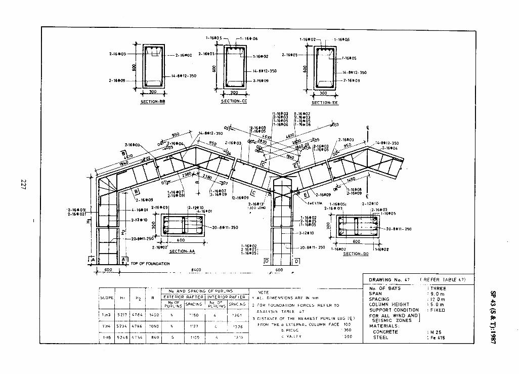
Z-16M9-
Z-16*02
l-16*0+ r-l- 16CO6
SECTION-BB SECTION-CC
--l-16*02
- IL-6@12-3S0
-2-16109
2-16*03
l-16*02, --l-16*06
l-16*05
14-6912-350
2-16*09
SECTION-EE
,
250
2-16KI21 5ECTlON-AA
. .F_^..
-20.Wll- 250 1-16~05 SECTION-CID
lx !w TOP 0F FOUNDATION iv I II”’
1 600 1 6400 600 ? 1
__---- ___~~ ~_f-- -_c
DRAWING No. 47 I REFER TABLE 471
No AN0 SPACING OF PURLINS No. OF BAYS : THREE
EXTERIOR RAFTER] ,NTERlOR RAFTER _ NOTE SPAN : 9.0m
SLOPE ti, H2 R . 1 ALL CIMENSIONS ARE IN mm
p;,$& SPACING j ;;R;LS 1 SPAC!NG SPACING : !2.0m
2 FOR FOUNDATION FORCES REFER TO COLUMN HEIGHT :S.Om
ANALYSIS TABLE 47 SUPPORT CONDITION : FIXED 1 in3 5217 47.94 1400 5
3 DISTANCE OF THE NEAREST PURLIN LUG (c! FOR ALL WIKD AND
SEISMIC ZONES I 1in4 5234 1766 1050 5 FROM THE o EXTERNAL COLUMN FACE 100
MATERIALS: b R!DGE 360
CONCRETE : M 25 1 in5 5246 475L BLO 5 c VALLEY 300 STEEL : Fe 415

2 - 20*)4
2-16111. B 8 w
-
l-20803 2.
I SECTION 88 SECTION CC SECTION EE
I
TOP OF FOUNOATION SECTION DO
____E!__.__ -__ -+--+ DRAWING No. 48 (REFER TABLE 48)
R
-__+ ! 2. FOR FOUNDATION FORCES REFER TO
_ I ANALYCJIS TABLE : LB
3 DlSTANCE OF THE NEAREST PURLIN LUG (cl
FROM THE (1 EXTERNAL COLUMN FACE loo
No. OF BAYS : THREE SPAN : 9.Om SPACING : 12.Om COLUMN HEIGHT : 6.5m SUPPORT CONDITION : FIXED FOR ALL WIND AND
SEISMIC ZONES I MATERIALS:
CONCRETE : M25 STEEL : Fe415

L
tlOhO3 Z-16602 2-l-03
16-6*09-350 16-O* 09-350
2-16’806
SECTION-86 SECTION-CC SECTION-EE
2-16606’
2-16#02 2-16*03
20-MO6 - 250
SECTION-DO
TOP OF FOUNDATION
1 600 I?100 1 600 L , 1 1 1
No. AND SPACING OF PURLINS
SLOPE ll, li2 R EXTERIOR RAFTER 1 INTERIOR RAFTER NOTE :
1. ALL DIMENSIONS ARE IN mm
2.FOR FOUNDATION FORCES REFER TO
ANALYSIS TABLE: L9
3.DISTANCE OF THE NEAREST PURLIN LUG cc,
FROM THE a.EXTERNAL COLUMN FACE: 100
b.RIDGE : 300
c.VALLEY : 300
.250
DRA’iING No. 49 (REFER TABLE 49)
No. OF BAYS : THREE SPAN : 12.Om SPACING : 6.0m COLUMN HEIGHT :S.Om SUPPORT CONDITION : FIXED FOR ALL WIND AND
SEISMIC ZONES 1 MATERIALS:
CONCRETE :M 25 STEEL : Fe Ll5

1 1 SECTION-EF
TOP OF FOUNDATION
DRAWING No. 50 (REFER 1ABLE 51))
No. AND SPACING OF PURLINS No. OF BAYS I THREE
. NOTE: SPAN :12.0m SLOPE H, H2 R EXTERIOR RAFTER INTERIOR RAFTER
pNuod;;s SPACING p$;$s SPACING 1.ALL DIMENSIONS ARE IN ,-,,,,, SPACING :6.0m
2.FOR FOUNDATION FORCES REFER TO COLUMN HEIGHT :6.5 m
SUPPORT CONDITION : FIXED 1 in 3 6717 6284 1900 6 1248 6 1145
ANALYSIS TABLE : 50
3.DISTANCE OF THE NEAREST PURLIN LUG (f) FOR ALL WIND AND
SEISMIC ZONES I
1in4 6734 6266 1425 6 1219 5 1396 FROM THE o.EXTERNAL COLUMN FACE:100 MATERIALS:
b.RIDGE : 300 CONCRETE IinS
:M 6746 6254
25 1140 6 1205 5 1380 c. VALLEY : 300 STEEL : Fe 115

s[7~4:
Szw:1331s
313tKIN03
:S7VIM31VK’4
[.;3%;/$%’%,
a3x14:NOlllaN03lNCZddfISlUs6:1H913HNWf1703UJl).g:‘3N13VdSUJo”zl:NVdS
338H1:SAVE30‘ON
(Is3m3vlM3+3H)IS‘ON9NIMV80
OocA371VA3OwtsSOLL907119S2697(.6Ooc!
sVI,;
3CKIIHqIII[11
I00133V.4NWn1021VNK!1X3D3H1WC)H4
L
96CLs61zl9SZ71
IIIIIM----l
99z6117U67U!L
(t)~fllNiltKd1S38V3N3H1403>NVlSi0C,-.
S71i997ZL9 1S319V1SISAIVNV006198Z6L1L6/CU!I
01M343LIS33M04NOllVONn04MO+t~N,3vd~SNllHnd~N12vdsSNllkJnd30‘N40“ON
[U(AJN,31JvsNo,sN3w,o‘,]v.~H31,3VUMOIL+31NId?J14VMt101t13LX3iiz~1“3dOlS
:31ONSNllLllld409N13VdSONV‘N
aa-Nou33s120s91-ZI
asz-t14wat-
1L-1
I1m
IJ2QJ
Osz-Lluz-8r90491-2ob91-z
ao9
LT
L009
LL.1aavtt1009
L7!lElr
NallvaNnod40KMv:
VV-N01133S120491-2
,...ojz-zlq-~ ..—..
70#91-zI1s04);1-2[~.11..,-.....11*21-Z704)91-2VM1,,..
i
:Zvo491-to*9t-ZO*91-Z
VU1X3-SMNI133MIU
Osf
,,.,..-

SECTION 88 SECTION CC ___- SECTION EE
17-81111- 300
17-8X12- 300
TOP OF FOUNDATION
i REFER TABLE 52 1
1
-- NOTE -!
Ati DIMENSIONS ARE IN mm
FOh FOUNDAT:ON FORCES REFER TO
ANALYSIS 7ABLE 52
DISTANCE OF THE NEAREST PURLIN LUG (q,
FROM THE G EXTERNAI. COLilMN FACE 100
b RIDGE 360
c VALLEY 300
No. OF BAYS SPAN SPACING COLUMN HEIGHT SUPPORT CONDITION FOR ALL WIND AND
SEISM!C ZONES 1 MATERIALS.
CONCRETE STEEL
: THREE : 12.0m : 12.Om : 5.0m . FIXED
M25 : Fell5

‘4 w w
SECTION 88 SECTION cc SECTION EE
_~___ ll-3oa L 1
j lttql j ‘- /2_$~;--“‘3-2”Ol 21.wfo- 300
l-25*03
iizll I II~~POFFo”NDA,K)N~ECT’~AA dlzlt
w Q SECTION 00
r 7 1 1 600 1 11400 1600 L
1 1 1 1 DRAWING No. 53 (REFER TABLE 53)
r No. AND SPACING OF PURLINS
’ No. OFBAYS NOTE : SPAN
SLOPE Ii1 H2 R . EXTERIOR RAFTER INTERIOR RAFTER 1. ALL DIMENSlONS ARE IN mm.
poplin SPACING c
,zjKN SPACING
SPACING 2. FOR FOUNDATK)H fDRCES REFER To COLUMN HEIGHT
ANALYSIS TAME :57 SUPPORT CONDITION
lin3 6717 6177 2007 6 1236 6 1133 3. DISTANCE OF TNE NEAREST PURLIN LUG (c, FOR ALL WIND AND
FROM THE a. EXTERNAL COLUMN FACE : 100 SEISMIC ZONE s I
lh4 6734 .615L 1536 6 1207 5 1361 b. RIOGE : 360
MATERIALS: CONCRETE
lin5 67f.6 6130 ’ 1256 6 1193 5 1365 c.VALLEV : 300 STEEL
: THREE : lZ.OflJ : lZ.Om : 6.5m : FIXED
: M25 : Fe416

.
b
Slf Y : 1332S
SEW ; 313113103 : SlVIY31V w
saNO2 3lWSl3S
ONV CINIM nV llO3
a3xld : NowaN lmddns Wtj.6 : lW313H NWil103
‘UO’LL : 9N13VdS
UJoIx : NVdS
3WWl : SAW JO ‘ON (7S318Vl ki3331) 7s ‘ON CJNIMVYO
OOE : h3llVA ‘3 5961 S E6LI 9 OTU 7SSE6 91L6 SU!l
099 : 32)a ItJ ‘4 lOE1 S LOLL 9 SZCl 9926 XL6 vu!!
001 : 33V4 NWlnOJ lVNY31X3’D 3l.U WOLld
(3) 9Il-l NIlMIld lS3YV3N 3Hl JO 33NVlSta’t EC11 9 9621 9 0061 7626 LlL6 tU!L
75 :318Vl SISAlVNV . I L i I I
01 8393~ S3X4Od NOIlVONflOd UOJ’Z 3Nl3VdS ‘$?$ E)NJJVdS S’$“J”d
ulul NI 3LIV SNalSNlWla 1lV ‘1 U31dVU UOlki31NI 1 M31dVY klOIY31X3 u zn ‘H 3dOlS
:310N . SNIlMnd JO 9NIJVdS aNV ‘ON
L L 1 009
1 L Is 00711 1 009 1
NOIlVaNfKU d0 dQL
b-NOllJ3S
33’NOl133S 3YNOllmS
+--T-4 OIY 91 -z
05t-7119-v1 5
iiiz 7onsz
90+sz -z LOru-I
L L
-e1
IIII
01.91-L
8 06c-cute-et
20*9z-z EO#SZ -,
-ol*91-9
mnsz -z

l-20*02, r1.20U04 ‘-2?*021 -I-20*04
2-12 (ill M-8116-260
- 2-20903
-36-8#16. 2-12112
,260 260
SECTION-W SECTION-CC SECTION-EE I
- J-1Dl”P
I I 2.11 r13
21-8wL-320 21-8.15- 320
No AN0 SPACING OF PURLINS NOTE: No. OF BAYS : THREE SPAN
SLOPE H, H2 R EXTERIOR RAFTER INTERIOR RAFTER 1. ALL DIMENSIONS ARE IN mm. : 1LOm
pNuqj& SPACING pi& SPACING
SPACING : 6.Om 2. FOR FOUNDATION FORCES REFER TO COLUMN HEIGHT : 6.5m
ANALYSIS TABLE : 55 SUPPORT CONDITION : FIXED lin3 6789 6212 2867 8 1358 8 1270
3. DISTANCE OF THE NEAREST PURLIN LUG CC, FOR AU WIND AND
SEISMIC ZONES I : lin4 6813 6188 2150
FROM THE a.EXTERNAL COLUMN FACE : 100 8 1327 8 12LO
b.RIDGE : 300 MATERIALS:
lin5 6828 6172 1720 8 1312 8 1225 c. VALLEY ; 300 CONCRETE : M25 STEEL : Fe415

SECTION-FIR SECTION-CC PECTION-EE
?I1 1 1 II$Topw_ToN SECnON-U. !z ,EL* 17200 i 000 ,
SECTION-DO
DRAWING No. 56 (REFER TABLE 56 )
No. AND SPACING OF PURLINS - No. OF BAYS : THREE
NOTE: EXTERIOR RAFTER INTERIOR RAFTER
SPAN : 19.Om SLOPE H, H2 R 1. ALL DIMENSIONS ARE IN mm
&$;;S SPACING p$Ly;s SPACING 2. FOR FOUNDATION FORCES REFER TO
SPACING : 6.0m COLUMN HEtGHT : 9.5m
ANALYSIS TABLE : 56 SUPPORT CONOtTtON : FIXED lin3 9769 9212 2667 6 1356 6 1270
3. DISTANCE OF THE NEAREST PURLIN LUG (cl F~~,&pg$NO] : lillb 9613 9108 2150 6 1327 6 1240 FROM THE a.EXTERNAL COLUMN FACE :lOO
b. RIDGE : 300 MATERIALS:
CONCRETE : M25 lin5 9626 9172 1720 6 1312
a 1226 c.VALLEV : 300
STEEL : Fe 415
.6#14-320

36-8*18-260
SECTION.BB SECTION.CC --
,36-BWO-260 AWJ ,36-S*lO;zco
‘3-Za’o,,0.8#17.j20 _ ̂ ^....^
4 ml I 17200 SECTION-DO __.___~__ .__ ~-~- DRAWING No. 57 (REFER TABLE 57)
No AN0 SPACING OF PURLINS NOTE,
RAFTER INTERIOR RAFTER , ALL DIMENSIONS ARE IN mm.
p”;kp,Ls SPACING &Rp;Fs SPACING i’ rA,:;UsN”:,“E” : gF:CES REFER lo
1358 I 6
1270 3 DISTANCE OF THE NEAREST PURLIN LUG&
FROM THE a. EXTERNAL COLUMN FACE:100
b Rl”GE : 300 I I I I I I I
- __-
1 in5 12828 12172 1720 e 1312 a 1225 c. VALLEY : 300
No. OF BAYS : THREE SPAN : lb.Om
SPACING : 6.0m COLUMN HEIGHT : 12.5m SUPPORT CONDITION : FIXED FOR ALL WIND AND
SEISMIC ZONES 1 : MATERIALS : CONCRETE : w2s STEEL . hblS

SECTION-BB SECTION-CC SECTION-EE
I II’ I I
TOP OF FOlNOATlON SECTION-AA
17200 L9oo 1 1 KcT’oN-op GDR*WIWO N o. 58 (REFER TABLE58)
No. AND SPACING OF PURLINS NOTE:
SLOPE H, H* R EXTERIOR RAFTER INTERIOR RAFTER 1. ALL DIMENSIONS ARE N mm
$i& SPACING P$i& SPACING 2. FOR FOUNDATION FORCES REFER TO
1 in 3 6789 6135 2916 9 1350 9 ANALYSIS TABLE : 50
l2l46 3. DISTANCE OF THE NEAREST PURLIN LUG ($1
lhL 6813 6109 2232 8 1319 6 1254 FROM THE 0. EXTERNAL COLUMN FACE: loo
b. RIDGE : 360
lin 5 6826 6086 1006 0 1301 8 1239 c. VALLEV :550
No. OF BAYS SPAN SPACING COLUMN HEIGHT SUPPORT CONDITION FOR AU WIN0 AN0
SEISMIC ZONES 1 MATERIALS: CONCRETE
STEEL
: THREE : lG.Om : It.Om : 6.5m : flXED
: w25 : Fe 415
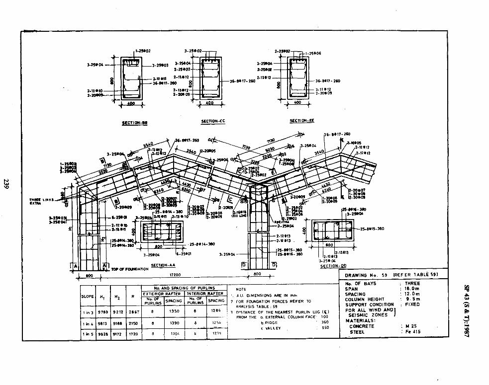
2-n 811 36Wl7.
SECTION-CC SECTION-EE
SECTJON-AA Top ff FOUNOATION
“-,..,.I
1%25+ 04
SECTION-LID
1 1 wo 1 17200 1 800 i (REFER TABLb 59) ? 1 1
DRAWING No. 59
No. AND SP*ClNG OF WRLINS NOTE EXTERIOR RAFTER
SLOPE H, n2 R - INTERIOR RAFTER 1 ALL DIMENSIONS ARE IN mm
$i;Gs SPACING PFRL$ SPACING 7 FOR FOUNOATION FORCES REFER TO
ANALYSIS TABLE : 59
I in3 9709 9212 2867 8 1350 8 1286 , 7 DISTANCE OF THE NEAREST PURLIN LUG (E)
- FROM THE (1 EXTERNAL COLUMN FACE 100
b RIDGE 360
c VALLEY : 550
No. OF BAYS : THREE SPAN : lG.Om SPACING : 12.Om COLUMN HEIGHT : 9.Sm SUPPORT CONDITION : FIXED FOR ALL WIND AND
SEISMIC ZONES I MATERIALS:
CONCRETE : M2S STEEL : Fe Llf

2-321)3
2-32W6
2-12 u12 -36-6W7-260
2-32803
>ECTION.BB SECTION-CC SECTIONJIE I
I 3-2OW9
2-12W3 2-Q l l:
2-j2103 J , ..a.,..
m2* - I
17200 1 600 i, 1 1 SECTION-DQ 1 DRAWING No. SO (REFER TABLE 60 I I
No. OF BAYS : THREE SPAN : lS.Om SPACING : lZ.Om COLUMN HEIGHT ’ 12.5m SUPPORT CONDITION 1 FIXED FOR ALL WIN0 AND
SEISMIC ZONES 1 : MATERIALS:
CONCRETE : n25 STEEL : Fe415
No. AND SPACING OF PURLINS NOTE :
SLOPE H, H2 R EXTERIOR RAFTER INTERIOR RAFTER 1, ALL DIMENSIONS ARE IN mm.
pNuodf:NS SPACING pN;rRffNs SPYCING ’ 2. FOR FOUNDATION FORCES REFER TO
lin3 12769 12212 2667 ANALYSIS
1350 TABLE : 60
6 9 1266 3 DISTANCE OF THE NEAREST PURLIN LUG(c:
1 in4 12613 12168 2lSO e 1319 6 1254 FROM THE a. EXTARNAL COLUMN FACE: 100
b. RIDGE .360 1 5 12826 12172 1720 a 1304 6 1239 E. VALLEV : 550

l - 16*03
Z-Km6
1%#06-270
2-16*07
m2-16*06 1
SECTION- CC
270
2-16606
17-6WJ9-270
2-16*07
SECTION- EE
-516+06
2-16#0L
17- 8,09- 270
- 2-16*07
SECTION-FF
-
2
3
NOTE :
ALL DIMENSIONS ARE lN mm
FOR FCUNDATION FORCES REFER TO
ANALYSIS TABLE : 61
DISTANCE OF THE NEAREST PIJRLIN LUG cc) FROM THE a. EXTERNAL COLUMN FACE: 100
b. RIDGE : 300
c.VALLEV 300
No. OF BAYS SPAN SPACING COLUMN HEIGHT SUPPORT CONDITION FOR ALL WIND AND
SEISMIC ZONES 1 MATERIALS :
CONCRETE STEEL
: r”“Ii
: 9.0m ! 6.0m : S.Om : FIXED
: M25 : Fe Cl5
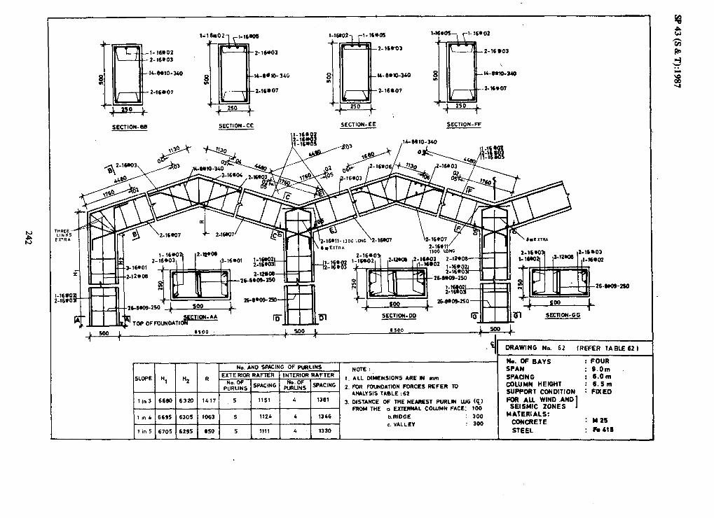
1-16902~ r!- 16W9
l- 16802
Z-16.03
ICMlO-34O
2-16407 iB 2- 16*03
0 l4-8dlO-3CQ
2-16*07
fa l-16*05 -, yl-16@02 e I
Jw 2-16*03
\
5t IL-8WO-340
tl6*07
SECTION-W SECTION- CC SECTION-EE SECTION-FF
1 SECTION-DO
I
-
1.
2.
3.
NOTE :
ALL DIMENSIONS ARE M mm
FOR FWNDATION FORCES REFER TO
ANALYSIS TABLE : 62
DISTANCE OF THE NEAREST PURLIN LUG (cl FROM THE a EXTERNAL COLUMN FACE: 100
I in L 6695 6305 1063 5 112L 4 13b6 b.RIDGE : 300 E. VALLEY : 300
1 in 5 6705 6295 650 5 1111 L 1330
No. OF BAYS : FOUR SPAN : S.Om SPACING : 6.Om COLUMN HEIGHT : 6.6m SUPPORT CONDITION : FIXED FOR ALL WIND .AND
SEISMIC ZONES I MATERIALS:
CONCRETE : Y26
STEEL : Fe416

Z-16903 2-16904
lCIUl3-350
246tO9
SECTION-BB SECTlON-CC SECTION- EE SECTION- FF
$U.IL_LU$TOP OF FoUNDPIT~O~~~~~~~-** ’
-6912-250 600 t
I-K w SECTION-DO SECTION-GG
26-6w. ,250
1
-4 6oo : 6400
DRAWING Nc. 63 (REFER TABLE 63)
NSIONS ARE IN mm
OATION FORCES REFER TO
OF THE NEAREST PURLIN LUG (6) a EXTERNAL COLUMN FACE: 100
b.RIOGE
c.VALLEY
No. OF BAYS : FOUR SPAN : 9.0m SPACING ; 12.0m COLUMN HEIGHT : S.Om SUPPORT CONDITION : FIXED FOR ALL WIND AND
SEISMIC ZONES 1 MATERIALS:
CONCRETE : M25
STEEL : Fe415

I Z- 16R03
Z-169 04
8 14-8,17-350
m
Z-16&13
SECTION-88
Q .-14-Ml7-350
2_l6*13
,*I?? - -2-16tm
.5ECTION- CC SECTION-E< &ECTI’JN-FF
L 600 L 9400
1
,/ 2- 16.09, n_rF..nG II-16(103
11 DRAWING Na 64 (REFER, 1ARLE 64 1
. . No.OFGAYS ; FOUR
ho.ANO SPACING OF PURLINS NOTE : SPAN : S.Qm
SLOPE H, bi2 R - EXTERIOR RAFTER INTERIOR RAFTER
1. ALL DIMENSIONS ARE IN mm SPACING : 120m
,“sd;Ls SPACING p;;L:;S SPACING 2. FOR FOUNDATION FORCES REFER TO COLUMN HEIGHT : 6.Sm
ANALYSIS TABLE : 64 SUPPORT CONDITION : FIXED ’
1 in3 6717 6264 1400 5 1150 4 1361 3. DISTANCE OF THE NEAREST PURLIN WG (%I FOR AU WIND AND
SEISMIC ZONES I FROM THE a. EXTERNAL COLUMN fACE: 100
i in 4 6734 6266 1050 5 1122 4 1326 b RIDGE : 360 . MATERIALS:
: M25 I c. VALL EV : 300
CONCRETE
1 in5 6746 6254 940 5 1109 4 1310 STEEL : Fe415

SECTION-CC SECTION-EE SECTION-FF
, II DRAWING No. 65 (REFER TABLE 65 1
E’ NO. AND SMCINC OF PURLINS . NOTE:
SLOPE H, W2 R EXTERIOR RAFTER INTERIOR RAFTER
$$ lSPAClNG pzz& ISPACING
1. ALL DIMENSIONS ARE IN mm
2. FOR FOUNDATION FORCES REFER TO
# I I ANALYSIS TABLE : 65
lin 3 5217 4764 1900 9 1248 9 11.45 3. DISTANCE OF THE lEAREST PURLIN LUG @,
1 FRW THE a.EXTERNAL COLUMN FACE: 100
1 in 4 5234 4766 1425 6 1219 5 1396 h RIDGE : 300
1 in S 52;6 4754
c. VALL EV : 300
1140 6 1205 5 1390
No. OF GAYS : FOUR WAN : 12.0m
SPACING : 6.0m
COLUMN HEIGHT : 5.0m SUPPORT CONOlTlON : FIXED
poR AU WIND AND
SEISMIC ZONES I
MATERIALS ! CONCRETE : M25
STEBI. : Fe415

Z-16*03 Z-16*04
IC6ml3-350
Z-16009
2-16,OC
1
2-16004
SECTION-B8 SECTION- CC SECTION-EC SECTION- Fe
16-8*13-250 /
’ ii!dq=-=
600 1
SECTION-GG
L 600 L 11400 11400 600
1 1 ? - DRAWING No. ~66 (REFERTABLE 661
No AND SFCING OF PURLINS NOTE :
SLOPE H, H2 R EXTERIOR RAFTER INTERIOR RAFTER
PziLZS sPabui
1 1. ALL DIMENSIONS ARE IN mm
$Lf& SPAC'NG 2. FOR FOUNMllON FORCES REFER TO
ANALYSIS TABLE : 66 lin3 6717 6264 1900 6 1248 6 1145
3. DISTANCE OF THE NEAREST PURLIN LUG &I T FROH THE a. EXTERML COUIMN FACE: 100
li,,4 6734 6266 1425 6 1219 5 1396 hRlDGE : 300 I I
c.VALLEV : 300 lin 5 6746 62S4 1140 6 1205 5 1390
No. OF BAYS : FOUR SPAN : 12.0m SPACING I 6.Om COLUMN HEIGHT : 6.6m SUPPORT CONDITION : FIXED FOR ALL WIND AND
SEISMIC ZONES 1 MATERIALS:
CONCRETE : M25
STEEL : Fe&l5

I
2- 16UO3
El 2-169 04
l6-6+15-350
216+ 11
SECTION-E.9
416W6
E16UO3 2-166 01
1C6*15-350
2-16#11
l-16603- ,l-rsror l-l”““‘, rl-16003
socTloN-cc SECTION-EE SECTION- FF
_ I.-- - ----I 2-16604 1 / - ‘w .
,$$h@ 2_16)05 ,l6-6615-350
__d
w 2-16916-1300 LONG
03 l 04
6tO7
No. AND SPACING OF PURLINS NOTE :
SLOPE II, Ii, R EXTERIOR RAFTLR INTERIOR RAFTER 1. ALL DIMENSIONS ARE IN mm
&LgS SRW@ &L$ *ING 2. FOR FWNDATION FORCES REFER TO
I I ANALYSIS TABLE : 67
1 in3 9717 9264 1900 6 1266 6 1145 3. DISTANCE OF THE NEARIST WRLIN LUG CC,
FRDM THE a. EXTERIAL COLUMN FACE : 100
I in‘ 9734 9266 I625 6 1219 5 1396 h RIDGE : 300
c. VALLEY : 300
1 in 5 9766 9254 UC0 6 l2OS 5 t360
DRAWING No. 67 (REFER 7ABLE 67 1
No. OF BAYS : FOUR SPAN : 12.0m
SPACING : 5.0m
COLUMN HEIGHT : 0.Sm SUPPORT CONDITION : FIXED
FM AU WIND AND SEISMIC ZONES I
MATERIALS: CONCRETE : M 25
STEEL : FeL15

SECTION-BB SECTION -Cc SECTION-EE aCTION-FE
2-16905 ( ,194*13-35Ll /‘“By”
I 600 1’ 11400 1600 1 11bOo 1600 1 T . 1 k
+
DRAWING No. 68 (REFER lABLE68)
I No. AND SFACING OF PURLINS I NOTE :
/SLOPE Ii1 H2 R. I EXTERIOR RAFTER INTERIOR RAFTER
.$&$ SWING
1. ALL DIMENSIONS ARE IN mm
pN;L$S SP*CING 2. FOR FOUNDATION FORCES REFER TO
ANALYSIS TABLE : 66
1 in3 5217 1764 1900 6 1236 6 1133 3. DISTANCE OF TtiE NEAREST PURLIN LUG (Q) FROM THE a. EXTERNAL COLUMN FACE : 100 1 in L 5234 1766 1125 6 1207 5 1361 b. RIDGE : 360
c.VALLEV : 300
No. OF GAYS : FOUR
SPAN : 12.Om SPACING : 12.0m COLUMN HEIGHT : 5.0m SUPPORT CONDITION : FIXED FOR ALL WIND AND
SEISMIC ZONES 1 MATERIALS:
CONCRETE : M 25
1 in 5 5206 67% 1160 6 1193 S 1365 STEEL : Fe 415
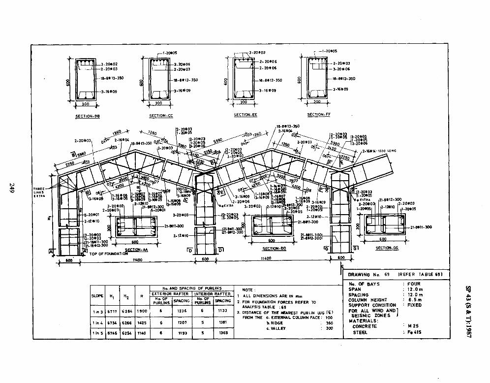
3.20006
2-20~03
ltl-6#13-350
3-16t)O3
SECTION-BE SECTION-CC SECTION-EE SECTION-FF
TOP OF FOUNDAT,- SECTION-DD SECTION-GG
11*00 1 600 L
I ’ I,‘.
-
c. VALLEY -----:3w
NOTE :
1 ALL DIMENSIONS ARE IN mm
2. FOR FOWMTION FORCES REFER TO ANALYSIS TABLE : 69
3. DISTANCE OF THE NEAREST PURLIN LUG cc)
FROM THE a. EXTERNAL COLUMN FACE : 100
h RIDGE : 360
‘1 DRAWING No. 69 (REFER TABLE 691
No. OF BAYS : FOUR SPAN : 12.Om SPACING : 12.Om COLUMN HEIGHT : 6.5m SUPPORT CONDITION : FIXED FOR ALL WIND AND
SEISMIC ZONE s I
MATERIALS: CONCRETE : M25
STEEL : Fe115

2-25*04
l&6*16-350
3-164t12
+,pq, _c:uw+
SEClION-BB SECTION-CC SECTION-EE SECTION- FF
11100 1600 1 11400 1 6 1 1 , 1
P
No. AND SPACING OF WRLINS NOTE :
SLOPE H, Hz R . EXTERIOR RAFTER IN7ERlDR RAFTER
No. OF 1. ALL DIMENSIONS ARE IN mm
PURUNS sRcmG P%L& WW’RG 2. FOR FCU?~MTION FQ)CES REFER 70
lin3 9717 9264 1900 6 12 36 6 1133 ANALYSIS TABLE : m
~3. DISTANCE DF THE NEAREST PURLIN LUG ((1
, in4 9734 9266 1425 6 1207 FROM THE a. EXTERNAL COLUMN FACE: 100
5 136l * P,RtT:C . IL,? I 1 I 1 I I I -...a”“_
1 in5 9746 925b II-40 c. VALLEY 6 1193 5 1365
aw
: 300
DRAWlNO N.. 70 (REFER TABLE703
No. OF OAYS : FOUR SPAN . 12.Om SMCINO I 12.Om COLUM HEIGHT : S.Sm
SUPPORT CONDITION : FIXED FOR AU WlND AND
SEISMIC 2ONES 1 MATERIALS :
CONCRETE : M25 STEEL : Fe 415

Z-?Zti6 3-16#05
2o#amto26-250
20.@09@26- 250 20-6+m9)026 -250
f OFtAWING No. 71 (REFER TABLI 71)
7 No. AND SPACING No. OF BAYS
OF PURLINS NOTE ONE
SPAN 1 ALL DIMENSIONS ARE IN mm
: 9.0m SLOF3! Hl tQ R ’ PRINCIPAL RAFTER SPACING : 6.0m
No.OF S~A,-NG .2 FOR R)lJNOATDN FORCES REFER COLUMN MEIGHT : 5.Om
PURLINS TO ANALVSIS TABLE: 71
3 DISTANCE OF 1% NEARL?LT PURLIN WG (6, StJPPWT CONOITION : HINGED
llnf 5260 4112 1367 5 1196 FOR AU WIN0 AN0
FROM TME a. EXTERNAL COLUMR FACE : 100 SEISMIC ZONES b. RIDGE
1n4 5306 4666 1025 5 .iim .300 MATERIALS :
: M25
1 I” 5 5322 4672 620 5 llS6 STEEL : Fe415

l DRAWING No. 72 (REFER 1ABLE 72)
3 -161102 l-1660) 3-166% I-
26-e4ito103S-250
26-6#tOto35-250
2-lwO7
16-6W9-260
* ._
i -16163
I---#-2-11ucJ
!iis!L J-WI06
I ,3- I 3-lW5 __.__. -_
3-t&2Tp~ ’ 2-l-11 A06 ’ 7-16M
SECTION AA L
26-6*lotJS-250
NOTE
ALL DIMENSIONS ARE IN mill
1 No.AND SPACING OF FURLINS
- 1 R
1 PRINCIPAL RAFTER
No. 04 2
PURLINS, SPACING
, m 3 ! 6762 / 6212 , 1367 5 1 1197 ,3
FOR FOUNOATION FORCES REFER TO ANALYSIS TABLE -71
DISTANCE OF WE NEAREST PWRLIN UlG(c)
FROM TttE .a EXTERNAL COLUMN FACE :x)0
b. RIDGE :300
No.OF BAYS
SPAN SPACING
COLUMN WEKaT 5WPCUT CONDITION FOR AU WIN0 AN0
SflSMIC ZONES
MATERIALS
STEEL
:DNE : 19.0 m :‘6.0m : ,6.5m : HINGED
: I425 : Fe415

Z-lZ#S
2-W.07
~RAWNO r40. 73 (REFER TABLE 73)
)(o.AYO 9mcIls lvOn
Of WRUMS
SLOPC nr nr I) - PRlRclPAL m 1 ALL omm9lous ARE IN mm
l&or !v*c*o I2 rnR noulKurm rOCLS RE?ER /, I PURLINS! to ANALYSIS TAu6-73
3 Dls1*acs of1mm&aesl rwl)cuG (6) 1nJ 53~5 ;46LO ) 1333 5 i nls Frnm we e.l!n cuuJwer*cr 100
-~ ~_ No. OF BATS SPAN !wMxNc COLUMN t+EyiHT
iG~u~tf60*bk0 xlsMlc ZONES
: ONE
: 9.0m
: 12.0 m : 5.0m : HINGED
b. RIOCE :360 MATERIALS tm4 5376 4610 1 1000 1 5 j 1166
I ax4caETE : M25
r I I I *CC* l--,.e tm5 5399 6590 I 900 1 5 i 1173 ZISLL l-I?*,3
9 e a R
J . . r
3

___---
1400 1 n&o0 +
DRAWING la.74 (REFER TAELE ?I)
SLOPE tit n2
No.ANO SP*uNC )(oIL
OF PWLIWS A . 1 ALL OIYCNShONS ARE IN 1)11)
PRINCIPAL WRY?%
p:::;* SPY% .2 FOR ~UNOATIDN FORCES REFER
TO ANALISIS TAOLE-74
I 3 OISTANCC OF lift! NLUEST WRLIN LUG cc) 1 m 3 I6849 6140 1333 5 1212 FROM lliE a. EXTERNAL COUIMN FACE : 100
No.ofBAvs SerN SPACING COLUMN NEGNT SuPmaT coNolnoN FOR AU WIN0 AN0
SEISMIC ZONES
ONE 9.0m
12.0m 6.5 m ljlNGEC

L
.
. ._- Cltllro3 C’ : ‘i
4-16902--1 N2W e-l@01 2od4co9to2 9LC7K)N * * 20-4Q9(029-250 20+$09102
3. DISTANCE Of THE NEAREST WRLIN LUG (ci )
FROM THE 0. EXTERNAL QKLJun fACE : ~~
DRAWING No. 75 (REFER TABLE 75)
No.OF BAVS : ONE SPAN : 12.0 m SPACING : 6.0m COLUMN HEGHT : 5.0m
SUPPOM CONOITION : HINGED FOR ALL WIN0 AN0
KISMIC ZONES MATERIALS
: M25
STEEL : Fe415

- l-l@03
- Z-l&m
26-81+(~-2~2E4J
l-wo3,
v b. RIDGE 300 MATERIALS 1 WlL 6809 6166 I400 6 1243
CDNCRETE : M25
1 tn s 6625 6172 1120 6 12 29 STEEL : Fe415
d
OUNOATION
i5WL 11 SoOc+
i-i&ING No. 76 (REFER TABLE 76)
1 I I I ND. OF BAYS
No. AN0 SPACING :ONE
nC DIIDI#UC NOlE SPAN :lZ.Om
I SPACING : 6.0m COLUMN HEIGHT : 6.5m
p;;;;s SPACING TO ANALVSIS TABLE-% m CONDITION : HINGED 3 DISTANCE OF THE NEAREST WRLIN LUG t%, FOR ALL WIND AND
1m3 6764 6212 1667 6 1272 FROM THE a. EXTERNAL COLUMN FACE :lm I SEISMIC ZONES

2-l-7
ii
- S-l-06
No. AND SPACING OF PURLINS NOTE
SLOPE n, & R pR,NC,p*‘ R*m* ’ ALL o’Y~NsNJ~ *RE IN mm N0.o~ SP*CWG
2 FOR rOllNOATDN FORCES RI?r+R
PURLIre m *II*LV~I~ ueu -77
’ 3 DISTANCE Of THE NLARfSl P!,bRLIN LUG (‘t)
lam 3 98% 9l40 1633 6 1295 FROM TWL o.EdlERNAL WuJMa FACE :1w
b. RIOGE :3Ca 1lnC 9885 9110 I 1375 6 126L
1 m 5 9906 9090 1100 6 1250
ORAWING No. 77 (REFER TA0lE 77)
ND. OF BAYS : ONE SPAN : 120m SPACING : 6.0m COLUMN HEIGHT : 9.5m SWf=ORT CONOITION : HINGED FOR AU WIN0 AN0
SEISMIC ZONES MATERIALS
: M25
STEEL : Fe415

--_I___.-___-. ..- .____ ___-___
,298426-210
SECTION 69 3-Qo5
k,‘ _n’ , ! <.I ~2sstt26-210
Z-1%407 _ I
2- IBOB_
z-18*
SECTION AA ~8*(01025-320
. . . 11 MO L soot
‘I .
~~i~5380 i 1375 i 6 / 1257 1
NOTE ALL DIMENSIONS AkE IN mm
FOR R)UNOAl(ON FORCES REFER TO ANALYSIS TABLE .I8
DISTANCE OF TME NEAROT PURLIN LUG ($ )
FROM THE a. EXTERNAL COLUMN FACE :100
b. RIDGE :36O
1 ,n 5 5402 I
A590 , 1100 6 124p
ORAWWG hb. 78 t REFER TABLE 78)
w.oFBAvs :ONE SPAN : 12.0 m SPACING :lZ.Om COLUMN nElGHl -: 5.0m
SWWRT CONOlTtON : HINGED FOR AU WIND AND SEISMIC ZONES
MATERIALS
:M25 STEEL : Fe 415
_--

.2-2am
2-l&09
1 500 t 11 500 1 500 7 1
DRAWING No. 79 (REFER TABLE 791
! No. AN0 SPACING I OF PURLINS
NOTE
SLOPE I Ill n2 R PFiNClPAL RAFTER 1 ALL DIMENSIONS ARE IN mm
-.2 FOR A)UNOATION FORCES REFER Iii. OFTpACING
1 i PURLINS I TO ANALYSIS TABLE -79
I / j 6651 / 6140 ; 1.933 ’ 1265
3 DISTANCE OF THE NEAREST WRLIN LLIG (t) 1 I” 3 6 fROM THE a. EXTERNAL COLUMN FACE : 100
No OF BAYS : ONE SPAN : 12.0m SPACING 12.Om COLUMN HEIGHT ! 6.5m SUPPOf?T CONOITION : HINGED FOR ALL WIN0 AN0
SEISMIC ZONES MATERIALS
CONCRETE : M25
STEEL : Fe.416
b RIDGE : 960
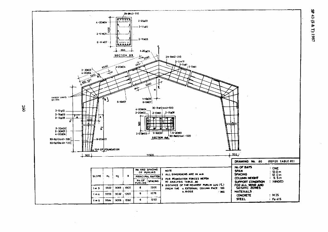
6-lta07 --
SECTION BB 29-w-210
CRAWIN M. 80 REFER 1ABLE 80)
I NChOFBAVS No. AN0 SPACING : ONE
OF PURLINS NOR SPAN
R --;--Ars 1 ALL DIMLWSIONS ARE IN mn SPACING : l2.Om : l2.Om
I - 2 WA rr)WOATION FOOCES REFE#
i I No.G~cw COLUMN MEKW : 9.5m
to ANALYSIS TABLE_60 SuPwmm :tllNGm i PURLINS! 1 3 DISTANCE of TNL NEAREST MLIN LUG t Q) F0R ALL WIN0 AN0
1 m 3 FROM ME a. E#lERNAL M)LlJYN FACE : KK) SEISMIC ZONES b. RIDGE :3W MATERIALS
lur4 o[)NcRElE : M25
tm6 STEEL : Fe415

SECTION 81
3-2Q?tO2
3- 2OR.D3
Zl-Mlkt31- 320 2H.Wlto31-320
No. AND SPACING OF PURLINS
NOTE
SLOPE Hl N2 R PRINCIPAL RAFTER . 1 ALL DIMENSIONS ARE IN mm
p,“;;;LS 1 SPACING 2 FOR FOUNDATION FORCES REFER
TO ANALYSIS TABLE-61
I 3 DISTANCE OF THE NEAREST PURLIN LUG llnl 6617 6176 28x) 6 1369 FROM THE (1. EXTERNAL COLUMN FACE
ImA 6646 6149 2136 6 j 1338 b. RIDGE
1 8” S 6664 6131 1710 6 j 1323
(Q) 100
300
DRAWING No. 81
No. OF BAYS
SPAN SPACING COLUMN HEIGHT SUPPORT CONDITION FOR ALL WIND AND
SEISMIC ZONES MATERIALS
CONCRETE STEEL
(REFER TABLE 81)
ONE
: l8.0m : 6.0m : 6.Sm : HINGED
: M25
: Fe415

SECTION BEAti 4celw-210
! ORAWING # 82 (REFER IAeLE82)
I No AND SPACING
OF PURL!NS _ --__--
PRINCIPAL RAFTEI
NOTE
1 ALL DlMENSlbNS ARE IN 11111)
2 FOR fOUNOATION F(YICES REFER 70 ANALYSIS TABLE - 82
3 DISTANCE OF THE NEAREST PURLIN LUG (%I FROM TME a EXTERNAL COLUMN FACE :lOO
b. RIDGE :300
No.oF eAv!i SPAN
: ONE
5aclNG : 1tkOm : 60m _._ . . .
coLuMNNf3Gm : 9.5m -oo(lomQl ~HINGED FORALL %tfiE? SEISMIC MATERIALS 1
:M25
REEL : Fe415

(REFER TABLE 83)
lb. AND SPACING r ~~ : ONE
OF PURLiNS Non SPAN : 18.0m
SLoPe n1 IQ R - 1
PRINCIPAL RAFlER ALL 0IMENSloNS ARE IN mm SPACING : 6.0m
No.OF -w 2 foR rcIuMo*TfL3H FORCES REFER C0LuhtNHEKiCn :12.5m
PURLINS TO ANALISIS TABLE _ 83
DISTANCE OF THE NEAREST WRLIR LUG (a)
~CONDlltGN : HINGED ‘3 FoRALLwlNOAm
lIlt3 t2924 12066 2800 6 1392 FROM THC o. EXTERNAL COLUMN FACE : 100 SEtSMlC ZONES L
In4 12961 12032 2100 6 1361 b. RIDGE :300 MAfERlALS :
: M25
llnl 12966 12OO6 1660. 6 1346 STEEL : Fe415
I

l-2om2 I.-,-‘(
2i-.3tm032-~20-J SECT,DN &A \\ I I II
17 500
OCIAWING No. 84 IREFER TA8LE8i)
No.AND SPACING OF PURLINS
NOTE ___.__.-__
SLOPE HI Ii2 R - 1 ALL DIMENSIONS ARE IN mm
PRINCIPAL RAFTER --m--r------ 2 FOR FOUNDATION FORCES REFER
No OF 1 SPACING PURLINS / TO ANALYSIS TABLE. 84
I 1369 3 DISTANCE OF THE NEAREST PURLIN LUG(c)
lm 3 6851 1 6140 2033 8 FROM THE a. EXTERNAL COLUMN FACE : 100 - -- b. RIOGE 360
11nZ 6883
---I 6110 ! 212s ,f 133;
-6o* 1700 e 1 0” 5 6903 ’ 1323
No. OF BAYS : ONE SPAN : 10.0 m SPACING : 12. Om
: 6.5 m COLUMN HEIGHT
SuPFORT CONDITION : HINGED FOR ALL WIN0 AND
SEISMIC ZONES MATERIALS :
ONCRETE :M25
STEEL :fe 415

,“REE LINK5 EXTRA
Pm06 2-12909 2-12 a0
4-iQaO2 C-2OW3
Z-1210
2-llm9
4-2WO7 Z-lZKJ8
4-7.0#2
4-2ono3 I-
L ‘OF OUNDATION i 4
DRAWING No. 65 (REFER TABLE 05)
I No. OF BAYS
I ! i .ONE
No AND SPACING NOTE SPAN :l80m
STEEL : Fe 415

j;i
ai3
2-12itll
z-ml0 -
6-2w -_ ._ 2-12Ar.09
J-=--J- 3~25m5 I
SECT’oN BB>+\ ,,& pW7-210
r-2104 I I II I I I I I/
3)_Btll41046-3
336+tl4to46-3 7-25 bO1
--_. . 33-6W4t.a 46-360 “SECnoN
_. A A
k
I
P OF GUNDATION
1 500-l 17500 --
1A BLE 86 )
r I I I i Nc.ANO SPACING 1
ISLOPE i “I 1 H2 1 R f-&&f~%&i/
/ 1m3 113026 ill960 2750 , 6 : 1409
NOTE ALL DIMENSIONS ARE IN mm
No OF BAYS SPAN SPACING
: ONE : lB.Om : 12.Om _ _..
FOR FOUNDATKIN FORCES REFER COLUMN HEtGHT : 12.5 m TO ANALVSIS TABLE _ 66
DISTANCE OF THE NEAREST PURLIN LUG (c) SUPF’CRT CONOITION : HINGED FOR ALL WIND AND
FROM THE a EXTERNAL COLUMN FACE :l@l SEISMIC ZONES b RIDGE :360 MATERIALS :
CONCRETE : M25 I In5 ‘13105 ’ 11605 ; 1650 e i 1362 STEEL : Fe415
I
i ,n 4 j 13074 / 11915 2063 i 8 1377

- --_.--_ --.-- . . --.-_-__ll_~ I_
l-2-2
3-25.#03
3-25dO8
SECTION BB 2-lam5 1
\ Li \72-8938170
3-251103 3- 2Suo4 I-
25-%x1310 37.
2H.sl3to 37.
2S+tl31e37-M0
25-8?kl3to37-390
1600 1 ’ 23400 1 500 1
DRAWING No. 87 (REFER TABLE 87 1
- No.AND SPACING OF PURLINS
SLOPE HI Ii2 R 1 PRINCIPAL RAFTER
11 1 1285 ‘3
10 ’ 1396
10 1380
NOTE
ALL DIMENSlONS ARE IN mm
FOR FOUNDATION FORCES REFER TO ANALYSIS TABLE _ 87
DISTANCE OF TM NEAREST PURLIN LUG (c) FROM THE a. EXTERNAL COLUMN FACE : loo
b. RlOGE 300
No. OF BAYS SPAN SPACING COLUMN WEIGHT SUPPCRT CONDITION FOR ALL WIND AND
SEISMIC ZONES MATERIALS
ONCRETE STEEL
: ONE : 24.0 m
: 6.0m : 9.Sm
: HINGED
: M25 : Fe415

\ --_a...-+-_ ._-.-._. ., -
li-Mbb-l/O
SECTION BB
1600 t 23400 1600 1
I NO AN0 SPACING OF PUALINS
1 In 5 I12987 I12006 2260 10 1366
DRAWING No. 88 (REFER 1AWE 88)
NOYE
ALL DIMENSIONS ARE IN mm
FOR fOlJNOATK)N FOFfCES REFER
TO ANALYSIS TABLE -88
DISTANCE Of 1tIE NEAREST PlJRLIN LUG tt)
FROM THE Q EXTERNAL COLUMN fACE :lKl
b RIDGE ‘300
ND. OF BAYS SPAN SPACING COLUMN HEIGHT
SlPPtXT CONOITION FOR ALL WIN0 AN0
SEISMK ZONES MATERIALS
CONCRETE STEEL
: ONE : 2L.Om : 6.0m : 12. 5 m : HINGED
‘M25
: Fe 416

1-32UO2 1 -, .,-.
EXTRA
z-32&3 Y_j I r2-‘6*1’ ^ __.-_
I
u-u--II
Z-32603
3-32w4
ZS-81cok87 -360
25mW7-3110
3-3 -32aol
SECTION AA
1600 t 23400
DRAWING No. 89 (REFER TABLE 89)
No. AND SPACING ’ NaOF BAYS
OF PURLINS NOTE : ONE
SPAN SLOPE Ii1 n2
: 24.0m --.- R - 1 ALL DIMENSIONS ARE IN mm
PRINCIPAL RAFTER SPACING . 12.Om
p;.j$;s 1 SPACING . 2 FOR FOUNDATION FORCES REFER COLUMN HEIGHT I 9.5 m
TO ANALYSIS TABLE -69 SUPPORT CONOlTlON : 1m3 I9923 9068 i3600 1 1302
__c_- 11 ’
3 DISTANCE OF THE NEAREST PURLIN LUG(c) FOR ALL WIN0 AN0 FROM THE a. EXTERNAL COLUMN FACE : 100 SEISMIC ZONES
1 In4 9961 9032 i 2850 10 / 13% b. RIDGE :360 MATERIALS :
--. cm 9985 9000 i 2280 10 j ,399
CONCRETE : M25
1 8” 5 STEEL : Fe415

Z-321103 3-3&04
3-6~14lob6_ 360
DIMENSIONS ARE IN mm
FOUNDATiON FORCES REFER
NALVSIS TABLE- 90 CONOlTlot4 :
STANCE OF THE NEAREST PURLIN LUG(t)
FRO,,, WE a EXTERNAL COLUMN FACE : 100 SEISMlC ZONES
b RIOGE
: M25
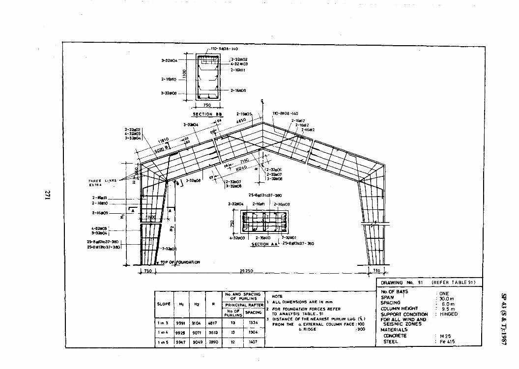
3-32&M 2-33so2 4-32003
2-1w11
SECTION BB
-l 750 ! 29 250
DRAWING NO. 91 .&FE!4 TABLE 91 1
Wo. AN0 SPACING OF FURLINS
NOTE
SLOPE Ml N2 R - 1 ALL DIMENSION5 ARE IN mm
PRINCIPAL RAFTER - 2 FOR fOUNOATK)N FORCES REFER
N~F~~~ACING PURLINS, TO ANALYSIS TABLE _ 91
’ /
3 DISTANCE OF THE NEAREST PURLIN LUG CF.) 1 WI 3 9991 9104 4817 13 1334 FROM THE a. EXTERNAL COLUMN FACE :lm
I b. RIOGE 1 mc 9925 9071 ( 3613 13 / 1304
:300
I
I Ill 5 I9947 i go4g ! 28got~l
~ I-O& BATS 1 ONE : 3G.Om
SPACING : 6.0m COLUMN HEKjnT : 9.5m SIJPf@4T CONOITION : HINGED FOR ALL WIND AND
SEISMIC ZONES MATERIALS
CCNCRETE : M25 STEEL : Fe415

4-=4---i OCIAWING No. 92 (REFER TABLE 92)
, I No. AND SPACING No.OF BAYS NOTE : ONE
OF PLIRLINS SPAN SLOPE Ii1 H2 --~-p-- 1 ALL DIMENSIONS ARE IN mm
: 3O.Om
I R ---- -- .-~~---~- PRINC!PAL RAFTER SPACING : 6.0 m
2 FOR KJUNDATION FORCES REFER p;;fL$=$PACING
COLUMN HElGHl : 12 5 m TO ANALYSIS TABLE_92 , SUPPCRT CONDITION
/ . 3 PISTANCE OF THE NEAREST PURLlN LUG (q) : HINGED
1 in 3 FOR ALL WIND AND -----‘~~~.~~~~-~~..~~~_~~~____ FROM THE a EXTERNAL COLUMN FACE x)0 SEISMIC ZONES
1 8” 6 b RIDGE ‘300 MATERIALS :
I CONCRETE 1 I” 5
: M25 lx)28 11967 2870 12 1416 STEEL 1 Fe415

uz
_- .-.
I---
L86
T :(
.L T
S)
EP
dS

4-32qo4
2-16~tl3
_ 2-32aO2
- 4-32-1(o)
- 2 -16M2
1 DRAWING NO. 94 (REFER TABLE 94)
I I I I 1 NO AN0 SPACING t NOTE
ALL OIMENSIONS ARE IN mm
FOR FUUNOATIGN FORCES REFER TO ANALYSIS TABLE-94
DISTANCE OF THE NEAREST WRLIN uIG( a)
FROM THE a EXTERNAL COLUMN FACE x)0
No. OF BAVS : ONE SPAN : 30.0m SPACING :lZ.Om COLUMN HEIGHT : 12.5 m
SUPPORT CONDITION : HINGE0 FOR ALL WIND AND
SEISMIC ZONES b RIDGE 360 MATERIALS
CONCRETE
STEEL : M2S
: Fe415

3-16M6 Z-123107
SECTION BB SECTION CC
L4oa 1 6600
7 DRAWlNG No. 95 (REFER TABLE 95)
. No. Of BAYS : TWO No. AND SPACING OF FURLINS NOTE
ExTEAlOR RAflER W=“I Hz R-
INTERIOR FUFTER ‘SPAN : 9.0 m
,. Al_LOlMENSlONS ARE IN mm SPACING ,6.0m MoF SlaCING pt$“p:
FumIN5 L S SPACING 2 R)R FOUNOAT’KW FORCES REFER lU COLUbw HElWl ’ ANALYSIS TABLE -95
1” 3 5260 4712 l367 5 1196 4 1361 3 GI5TANCE OF ME NEAREST PURLIN LUG(q)
FRO&, THE o. EXTERNAL COLUMN FACE ‘100 SEISMC ZONES Ifn4 I 906 4666 1025 5 1170 4 1346 b RIDGE :3m MATERIALS :
c VALLEY :300 : M 25
rn5 5322 4672 620 5 1156 4 1330 :Fe415

/ l&81137-260
,18-t3@7-260
3-16406
26-6#tlto36-250
L-IGUV 2-12IO8 I 7-16tm
26-Bpllto#-250 26-Bdlto36-250
__ __..~___ ___
-4
Na.ANO SPACIW OF FVALINS
SLOR n, Hz R EXTERtOA RAFTER 1 IMERLYl RAFm NmE
ALLOtMENY0((5 ARE IN I)LI1
IOR FCUNMYDN FORCES REFER 10 MALI sts TheLt - 96
ln3 6782 6212 l36f 5 1197 4 1381 3. OISTAMCE OF lnE mEAmEs PmLlN LUG (0
” FROC THE a. EXTERNAL ODLlJWt M: 100 tm4 61307 6188 1025 5 1168 4 13b6 b. RIOGC : 300
c *ALLET :x)0 1-S 66% 6172 820 S 1155 4 1330
ORAWNG No. 96 (REFER TABLE 966)
No.OFBAYS !fW SPAN : 9.0m SPACING : 6.Om axuM MElerr
MAlEmMs: - : M25
STEEL : :ee415

, , lSat3l- 260 ,lb#31-260
2-12+07
2-?24#3.
b-1&02 L-l6#03 !
Pfmlto3~
x)-6tHltoxJ~
x 4 -250 -250
-I
ZO-lwttc
MON
--A !30-250 SECTION AA 20
2@
2-12490
3-mao2 4-leuO3 l-l&@5
+mlb 30
-6aFllto30
Z-1692- ,IGG LONG 8, EXTRA 2o-wlto30-550
3. DISTANCE OF lWC NEAREST MLIN LUG t%)
1000 5 ’ 1166 1 1326 b.‘WCGC : 360 - MMaaAls:
c VALLEV : 300 : M25
800 5 1173 4 1310 : Fell15
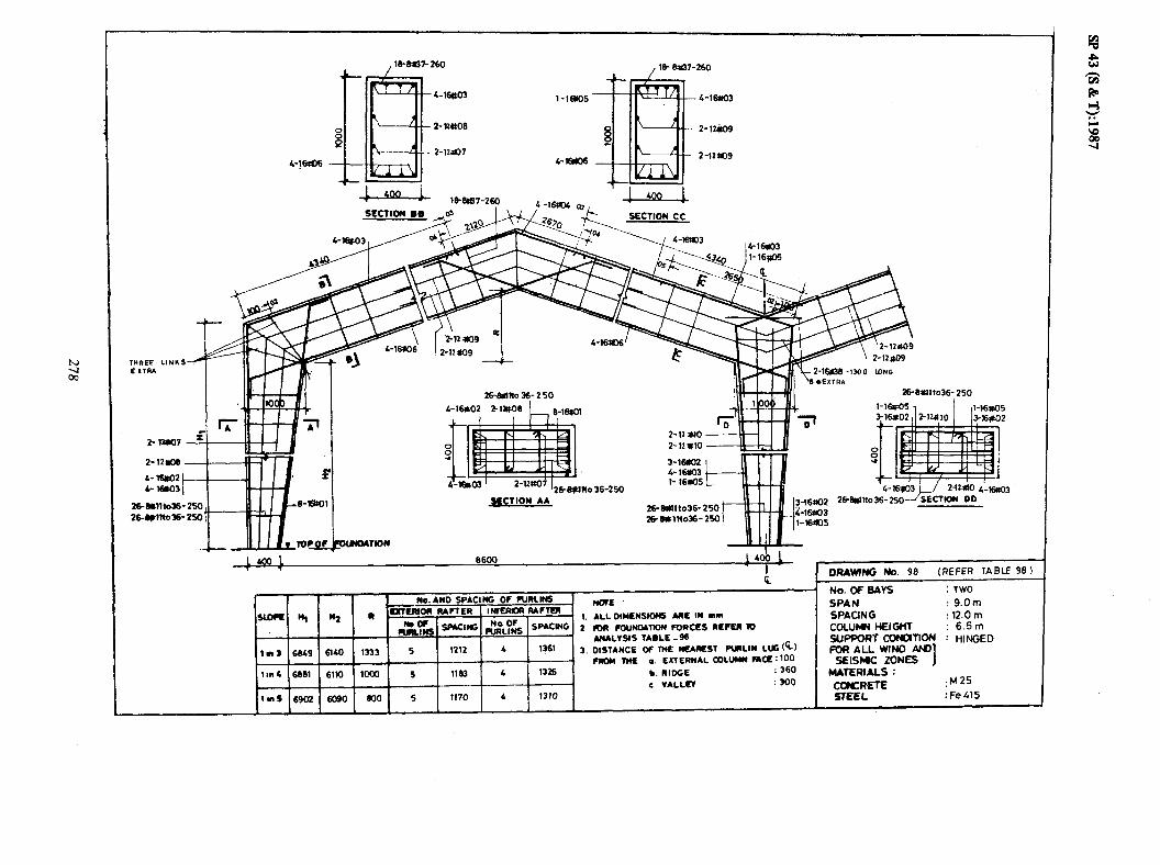
51!7%i: 7335
stw: WYW3 . s-ivlM3lvw
I S3Niz WSIK
u4v aNlMll*w a3FXJIH : NolAm IMaddns
w5.g : lH9IW twIlla w 0’21 : 9NT)VdS WO.6 : NMS
OMl : SAV0 30 ‘ON
(96 3lBtfl %k43to 96 ‘ON 9Nu1)310
009 : UllVA 2
09c : 3301u ‘P
001: 33VY NNITIQ) lVNU3113 ‘0 M m (,,Slll Ni-lMfld lS~T3N 3bU d0 3~NVlSlO ‘t
86- 319~1 snrtwu a m3d3Y S3~Uod NouvaNnoJl YQI 2
SNOISNPPllOllV ‘1
3
Iii I II SC@t-1 COW-~
w osL-9cwlLsu¶z OSz-9E~llD10-9z
VV NOll3k

I’ c
2-12NOl
El%@
4-l6?m2 L-l&403
+
2~&mY3O-EO 2(t6mn03e2x~
+- &OO 1 11600
ORAWNG No. 99 [REFER TABLE991
-250
=JkB T 77 812*10
2-m
l-la832 4-m 316w3
2ck5*nto30-2sl 20-wlto30-250
No.*no SPACING OP WRLINS
SLDFl! n, I43 R ’ EXTERIOR RAFTER IMERKm rUFlm
&ye SmCIwG &gLFti SPACNG
,r3 6202 4712 1867 6 1273 6 1145
1m4 5307 4688 1400 6 1243 5 13.96
,,ns 5324 4612 1120 6 1230 s l360
-
1.
2
3.
WTE ALLDIMENYOt6 *RE IN 1)(11 IOA fOIJNMTIoII FORCES REFU m ANALYSIS TABLE _ 99 DISTANCE OF M WUREST RLRLIN L&u fRCM lHE o. EXTERNAL aDLW AQ: 100
b. RISE : 300
c VALLO :3M)
No. Of GAYS : TWO
SPAN :lZ.Om SPACING : 6.0m CoLum HEioR : S.Om SWFORT cavomoN : HINGED
zkk”&- I i
MATERIALS :
EF :M25 :Fe415
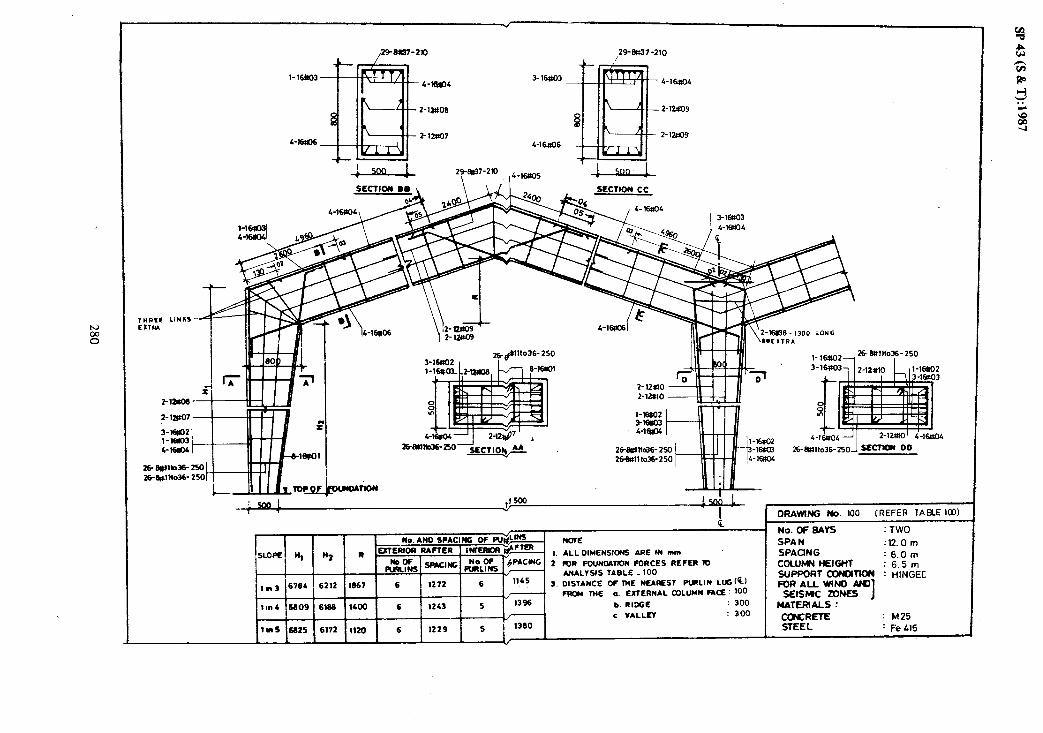
4-16806
-16lbn
SECTION DO SECTION cc
EXTRI THREE LINKI
.29-8057-210
4-16?!04
Z-12UOY
z-12QY
3-1602 l-l%33 6-m 26+lll~656- 250
26wll to36- 250
II l_lbtloz_2661tlllo36-250
i l-l6802 3-lmcn ,4-16sO4
4-l&04 2-1m’ i-s@4
26-&Fllto36-250 sLtZTIW DO
5ool ,f 500 1500 1 1 7 1 ’ DRAWING No. 100 (REFER TABLE IKJ)
1 No.OF BAYS : TWO
SPAN :lZOm
SLOPE n, n2 1. ALLDIMENSIONS ARE IN mm SPACING : 6.0m 1 IOR FOUNMRON FORCES REFER IO COLUMN HEIGHT : 6.5m
ANALYSIS TABLE _ 100 1145
SUPPORT coN)ITION : HlNGEC ,,,a 6704 6212 1867 6 1272 6 3. DISTANCE OF THE NE*REST PulLIN Lffi(G)
J FRCU WE a. EXTERNAL COLUMN RQ : 100 FORAlJ_WlNO AM
SEISMIC ZONES lnnb 6609 61% 1400 6 1243 5 13% b. RIOCE : 300
I MATERIALS :
r/ c VALLEV : a00 : M25 1-S 6825 6172 ltZ0 6 1229 5 1360 : Fe 415

32cw3
Z-121109
6-16107
SECTION 88
I!+ milo7
30-.9*IZto+32U
3-20#03. r 2-QeO9 I- -
30- 6#82k41-320
I I
2-2Oxt2
2-2GQOs
2-i
3-i
3M!U12to 41-320 2-:
c2ow2 3Pm3
T4
41-320 *6a2to4l-320
3oai2Io41-3’”
~OLJNMllON
1 1 11500 1 5cb 1 9nlY
1 ----r-r DRAWING NO. 101 (REFER TABLElOl) L
- No. OF BAvf : TWO
-3 -201103
2-124uo
2-123LIo
No. AN0 SPACING OF RIRLINS NOTE SPAN :12.0m
SLOPE N, Nz EXTERIOR RAFYER
R - IMERIOR RAFm
1. ALLOIMENSIM ARE IN mm SPACING : 6.0m &$ sbwclffi ,,$F& SPACING 2 R)R FOUNO*TION FORCES REFER 10 COLUMN HEIGHT : 9.Sm
ANALYSIS TABLE_101
3. DISTANCE OF THE NEAREST PIRLIN LlJGh)
SUF’PORT CZf’4DlTION : HINGED
1*3 9854 9140 1633 6 1295 6 1145 FOR ALL WIND nK) FROM THE a. EXTERNAL COLUMN F*= ! 100 SEISMC ZONES I
lll~ 9865 91x) 1375 6 12 64 5 l?% b RIDGE : 300 MATERIALS :
c VALLEY .300 : M2S I 1ins 9906 9090 1100 6 izso 5 \w : FeLlS

l-2oRO3 3-2CWO3 3-20004
16ulNO27~320
I 3-2WO2 16-WI2 to2?-320
IIP l-200) 2-law9 I 7-2oaa
15001 11 so0 I so0 1 1
DRAWN6 b. 102 (RERA TABLEIOZ) a
1. *LLIMEW~~~ *AE m IU
2 mOR FowM7lw FORCES REFEn 1D ANALVS(S TABLE -102
3. DISTANCE OF M )ILuLSl PWLIM LUG ((J
FAQY fnE a. EXTERNAL COLu*( KiWE:~ b. RIffiE
c VALLEI
No.oFmA*s : TWO SPAM :Q.Om -QNG :i2.Om colamNElGm : 5.Om %l-T - : HINGED
wwsm I MATEmAls :
: M25
f fi415

29-303-210 29-w33-210
l-20+03 3-mu04 fioPO3
z-ma9 z-l2mo
Z-law36
6-16~37 s-16aO7
2t--%lt12162-320
- --..-- i 2W44z(032-3M SECTION AA
OLWOATtON
1 l-2Om2 3-?om3
3-M)04
No. AND SPACING OF FURLINS NOTE
SLOPE n, nf R a EXTERIOR RAFTER INTERIOR RAFTER
1. ALLDIHENSION5 ARE IN mm
GLy* SPACING ,$L$$S SPACING 2 R)R FOUNMTION FORCES REFER 10 ANALYSIS TABLE. 103
,n3 6851 6140 1833 6 1285 5 1416 3. DISTANCE OF ME NEIRST PLMLIN LUG(E)
. FRW THE a. EXTERNAL COLUMN FA= : tw
ItnL 6663 6110 1375 6 1254 5 138 b. RIOCL : 360
- c VALLEV : 300
1-S 6903 6090 1100 6 1241 5 ’ 1365
1
l-zoM2 3-2CUO3&2~1
l-2wQ
3-MO3
DRAWING No. 103 (REFER TABLE1031
SPAN : 12.0m SPACING couJMh( H!EIGHl ; n8.g SUPPORT ConQ- : HlNCXlJ
FoxRLkw&- I MATERIALS :
: M25
: Fe415

L=d- 2981w-2x), 4_2oxos
II I .t~ewt14to29-320
2-12*3 %lPcIY
B-2owl
__ __ L.-.-._.__.
16-E#l4(029-320 16-Wl4to29-320 t
-1300 LONG A 16-66tCb29320
ME IN mm FORCES REFER 10
IELALVstS TA8LC -lob J. DISTANCO OF w NEARST CULIN US(~)
FRDbt ME o. EXTERNAL oMuyI( AQ: 100 b. RtD8E s vAuEv

C- 44-6#36-210
3-2WO2 3-2wo3
2-12+t.l2
21-WlSk66-320 1 2l-6tk15to35-321
I y)[) 1 17 500 I T 001
I - DRAWMG No. 105 RXFER TABLE1051
No. AND SPACING OF RlRLlN!
!vDR nt n2 R L Ex7ERlOR RAFTER I MERK
&yH SmCINt J!.?i
,nf 6617 6176 2650 6 1369
tan4 664s 6149 2136 B 1336 I I c VALLEV : 300 ln5 6664 6131 1710 8 1323. 6 1225
No. W GAYS : TWO SPAN : 18.Om SPACING : 6.Om cDuJw HElwl : 6.5m SUPf’oRT - ! HINGED FOR ALL WIND A)9
SEISMC ZoNa I MATERIALS :
rrmcI= . M25 Fe415
c&..nrlr STEEL

,44+lK6-210 ,+4- 6#66-210
S-16fMl -
3-2W4
l-25*02 I
256;(16bLO-360 1-gBt.O3;12-l2tn, rHZ*2
25.8 161040-3 25-3-411065-3
25-6d4lto65-360~~~,~ AA
2-25aO2 3-25W6 t-
25-%F16tc40-360 25-6#41b65390 t
N2-25n02 ’ 3-1yO6 2- 2W7
Ncm
1. ALLDIMENS10(6 ARE IN mm 2 R)R FOUNMllON FORCES REFER 10
ANALYSIS TABLE-106 3. DISTANCE OF lWE NEAREST FXRLIN LUG ($1
’ FROM THE a. LATERNAL COLUMN FACE :lOO b. RIDGE :300
I c VALLEV : 300
SPAN : 18.0 m SPACING : 6.0m COLUMN HEIGHT : 9.5m SUPPORT CDNOlTIm : HINGED t=oRAUwlNo 4\19
KlSr4c zws 1 MATERIALS : CONCRETE : MZ5
8 1225 1 STEEL : Fe415

N
3
3~25zfx
2-12#15
I ’ 336¶dmoM-380
IO0 12
3fkr D 7
2-lt117
33-tWW3-360 SECTION AA l-25lm3 l-2%04
33-wn6bso-360 33-6ss1i063-38
1. ALLDIMENSIONS ARE IN mm 2 mfl FOUNMM)N FORCES REFER 10
ANALYSIS TABLE. 107 3. DISTANCE OF THE lmAfiES1 PIRLII( Lu; (%)
FWbl IWE a. EXTERNAL COLUMN FAQ: loo
c VALLEV

THREE LlNRf EXTRA
,44-Ml-210 4L-tUtSl-210 /
i ,~ c_ ___
x; /i. TO~~OUNOATION
-.+-- i 17 500 *
k
. DRAWING No. 08 (REFER ‘TABLElOB)
No.ANO SPACING OF FWRLINS No.OfBAVS : TWO
NOTE
SLOPE n, H2 R EXTERIOR RAFTER I HIERIOR R4 F TER SPAN : 18.Om
pu%LT;S SPACIM; 1. ALLDIMENSIONS ARE IN mm SPACING ‘12. Om
- ;,&F):S SPACING 2 FCR FOUNDATION FORCES REFER RI COLUMV HEIGHT I
6. 5m
! ,fi 3 jS8Sl 6140 2833 ANALYSIS TABLE -100
8 1369
t,, :--KS
3 DISTANCE OF THE NEAREST PURLIN LUG tt, SUPPORT CONf3TlON : HINGE-J
/
FOR ALL WIND AKI FROM THE a. EXTERNAL COLUMN FACE’ 100
ton4 6883 6110 212s
%_+ _-7
SEISMIC ZONES I
_? .____ b. RIDGE : 360 MATEf?iALS : c VALLEY 550
6903 6090 1700 , 1323 ; 1378 CONCRETE : M25
I STEEL ! Fe 415
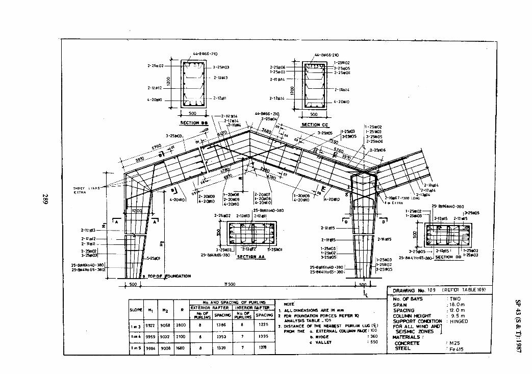
L
l-25%02 3-25so3 2-2%c6 3-25~05
l-2%!zo3 2-25x06 2-12*13 2-12#14
2-25to2, 2-12Sl3 1:2:010-3*0
2-12M3-
2-12912- WI 2-lwl ' .-
r
5-240,
I Z~BR16MO-380
,3-25%iO5 I 2-12zd5 2-1zms
-DRAV#lf’JG No. 109 (REFER TABLElOg)
-No. OF BAYS TWO SPAN : 18.Om SPACING : 12. 0 m COLUMY HElGw : 9.5m SUPPORT CONDlTION : HINGED FOR AU WIN0 ANJ
SEISMIC ZONES I MATERIALS :
: M25
: Fe415
1-25Itof' III I Ill LF?!Y ’
1-2%X ~~ 1 3-25UO5
25-8~6161~40-380 2WN4lto65-380
1. ALLDIMENSIONS ARE tW nn,
2 R)R FCUNMltON FORCES REFER 19 ANALYSIS TABLE - 109
2. DISTANCE OF WE Nl!A&W PLRLIN LUG(k)
fWM THE e. EXTERNAL DDCIJMN F*Q: 100
b. RIDGE : 360
c VALLEV : 550

2-11e- 2-nws-
l- 2Sno3
3-25002 3-29BOL t
33-e.w9to4~3m 33-fJH9104t d
._
l-2wO3
2-ma6 -
, 43-8042-210 . , 43 -&42- 210
- 3-2%04
-2-121s
- Z-12303
2-2sto4 3-2pO6 2-lZ#t’
2-12tr17
-8042 -;
il I I I I II 33-6m9to41-380 IcttoN DO
I 17 500
f)RAwNG No. 11G (REFER TABLE 110
- No. OFBAVS : TWO No. AND SPACt NG OF FURLtNS NOTE SPAN : 18.Om
SLOPE n1 n2 R EXTEMOR RAFTER I MERM RAFTER 1. ALLDtHENStONS ARE IN mm SPACING : 12. 0 m
&yw SPKING &$& SPACING 2 mR FO”NMllON FORCES REFER TO COLUMN HEIGHT : 12.5 m ANALVStS_TABLE - 110 SLIPPORT CONMTION : HINGED
I,,,) 13028 11960 2790 8 1409 6 122s 3. DISTANCE OF lHE NEAREST PURLIN LLG (%I FOR ALL WIND AN) FROM THE 0. EXTERNAL COLUMN FACE: 100 SEISMIC ZONES I
IIn a074 1191s 2063 6 1377 7 1395 b. RtDCE : 360 MATERIALS : 1 4
I c VALLEY : 550 CCNCRETE : M25
IInS l3109 11605 1650 8 1362 7 1376 1 STEEL : Fe415 1

---
72-8343-170
2% 6ul9toL2- 380 25-BDIBio 62-3 2~8Jmd.2 - 390 2w#.iw2- 360
DRAW,,& No.111 (REFFR TABLEIll)
G No. OFBAYS : TWO 7 No. AN0 SPACING OF FURLINS NOTE SPAN : 24.Om
SLOPE Ii, H2 R . EXTERIOR RAFTER ,NlERlDR RAFTER
1. ALLDIMENSIDNS ARE IN mm SPACING : 60m
GLSS SPACING ;;Ly;s SPACING 2 R)R FOUNDATION FORCES REFER TD COLUMV HEIGHT : 9.5m ANALVSIS TABLE -111 SUPPORT cwomm : HINGED
,mJ 9889 9104 3617 11 12.35 10 1311 3. DISTANCE DF l?iE NEAREST PURLIN Lffi&) FOR ALL WIN0 Ml
., FRoL( THE a. EXTERNAL CX)LUMN FACE: tf3, r,EISMC i0NES ]
lo”4 9924 9071 2963 10 1396 10 1250 b. RIDGE : 300 MATERIAL% :
c VALLEY : 550 CONCRETE : M25
1 tins 9946 9OA9 2290 10 1380 10 1265 STEEL : Fe415

33-&#l7bk9-380 3-25#.O2, 2-16lU4 12-l6d2
33-6wto4~360 SECTION AA
i6Ob t I -
1 DRAWlNG No. 112 LREFER TABLElIZ)
I Q_ No.OfBAYS : TWO
No. AND SPACING OF PURLINS NOTE IMERlOR RAFTU_
SPAN : 24.0m SLOPE q n2
EXTERIOR RAFTER R L - 1. ALLOIMENSIONS ARE IN mm SPACING $g& SFwlNG ,$T& SPA’.(NG 2 RIR FOUNOATION FORCES REFER 10
: 6.0m COLUMY kw3GMT : 12. 5 In
ANALYSIS TABLE -112 SUPPORT cotanow : HINGED *m 3 12925 12066 3600 11 1290 ‘0
1311 3. DISTANCE OF THE I(EAREST PtMLIN LUi cc) FOR ALL WIND L\H)
FRo*( THE a. EXTERNAL QDLUMN FA!!: 100 SEISMC ZONES I lm4 12963 lM32 2850 10 1401 10 1260 b. RICCE : 300 MATERIALS :
c VALLEV : 550 CCBICRETE : M25 1 I”5 12967 12008 2200 10 1366 10 1265 STEEL : Fe 415

t
2-lM13
ii 32+X
,3- 1
*&6k40-360 25-bL~tiO-BO
O-360 360 SECl!oN DO
-- 25-8+16t040-360
25-8t161046360
II I I I II I
DRAWING No 113 (REFER TABLE 1131
SLOPE n, Ii2 IMENSld ARE mm
, ##) 3 19923 9066 3600 ” _p j 3. DISTANCE OF WE NEAREST PULIN LUG t’i., FRCU THE Q. EXTEWAL COLUMN RQ : fiQ
141~4 9961 9032 2850 10 ; / 13%
‘O 1 ;;3cJ
10 b. RIDGE :36O
1 7 c VA,LLEV : 550
1 m9 9985 9008 2280 IO : 1360 10 lZS9
/
No. OF Bc\YS : TWO SPAN : 24.0m SPACING 12.0m COLIJMY MIGHT 9.5m _. _. SUPPORT I~MTION FOR ALL WIND AMI1
HINGED
KISMC ZONES j MATERIALS :
%F= : M25 : Fe415

2-32#02 3-32=#03
+t-
71-6Ftso-li; 71-8450-170 /
SECTION BB \ \,,
2-,~1-l3GGLONG G-2*10 33e.+u7w+9-360 __ _ .__ _ _^^
2-?.it$d6
1-321103, 1 2-lq6 J-32&33
L .I-37atO
b&9-3dO 33-0*7to49-360 SECTION AA 33-wl7lG49- 360
33-e#71&9-360
33-Bn17!049-380 -k600i 23 400 1
sGQJ_ ;, , No. AND SPACING OF PURLINS NOTE
SLOPE n, n2 EXTERIOR RAFTER R- I MERIOR MFTER
1. ALLDIMENSIW ARE IN mm
l$L%S Sp*cwks ,$j,$ SPACING 2 R)R FOUNMTKIN FORCES REFER 70 ANALYSIS TABLE_114
tm3 13027 11960 3750 11 1302 10 1304 3. DISTANCE OF lME NUREST PLRLIN LLG t%) FROM THE 0. EXTERNAL COLUMN FACE: 100
1,” 4 13075 11915 2613 10 1414 10 1273 b. RIDGE : 360 c VALLEY : 550
1mS 13106 11665 2250 10 1399 10 1259 m .
-32#)3 i-32& 2-i6Ul6
-32RO5 SECTION DO
DRAWING NO. 114 (REFER TABLE 114)
NO. OF BAYS : TWO SPAN : 24.0m SPACING 12.0m COLuMfu HEIGHT : 12.5m SUPPORT CONl3TlON : HINGED FOR ALL WIND ANY
SEIS)UPC ZONES 1 MATERIALS : CONCRETE : M25 STEEL : Fe415

SECTION 00
01 8600 I
DRAWING No 115 (REFER TABLE 115)
No. AN0 SP*CING OF PURLINS NOTE
-r, r, I)’ LJltlERlOR RAFTER INTERIOR RARER
c > 1. ALL OIMENSIONS ARE IN mm
zk SRLCING &p,, SPACLK. 2 FUR FWNDATIo( FORCES REFER TO I ’ ANALYSIS TABLE _ 115 ,*; 5280 4n2 1367 5 1198 4 1381 1 DISTANCE Of TM NEAREST PlJRLlN w cc)
FROM WE Q. UmRNAL CtXJMN FACE :lOO
1-4 5306 ~ “25 5 1170 4 1346 b. RIDGE : 300
ll# c.VALLEV :300
1ms 5322 4672 020 5 4 1330
: THREE : 9.0m : 6.0m SPACING
COLUMN HEIGHT : 5.0m SUPPORlCONUTKW’J : HINGED
FOR ALL WIND AK) SEISMIC ZONES I
MATERIALS : CUKRETE : Mzs
STEEL : fed15 ,
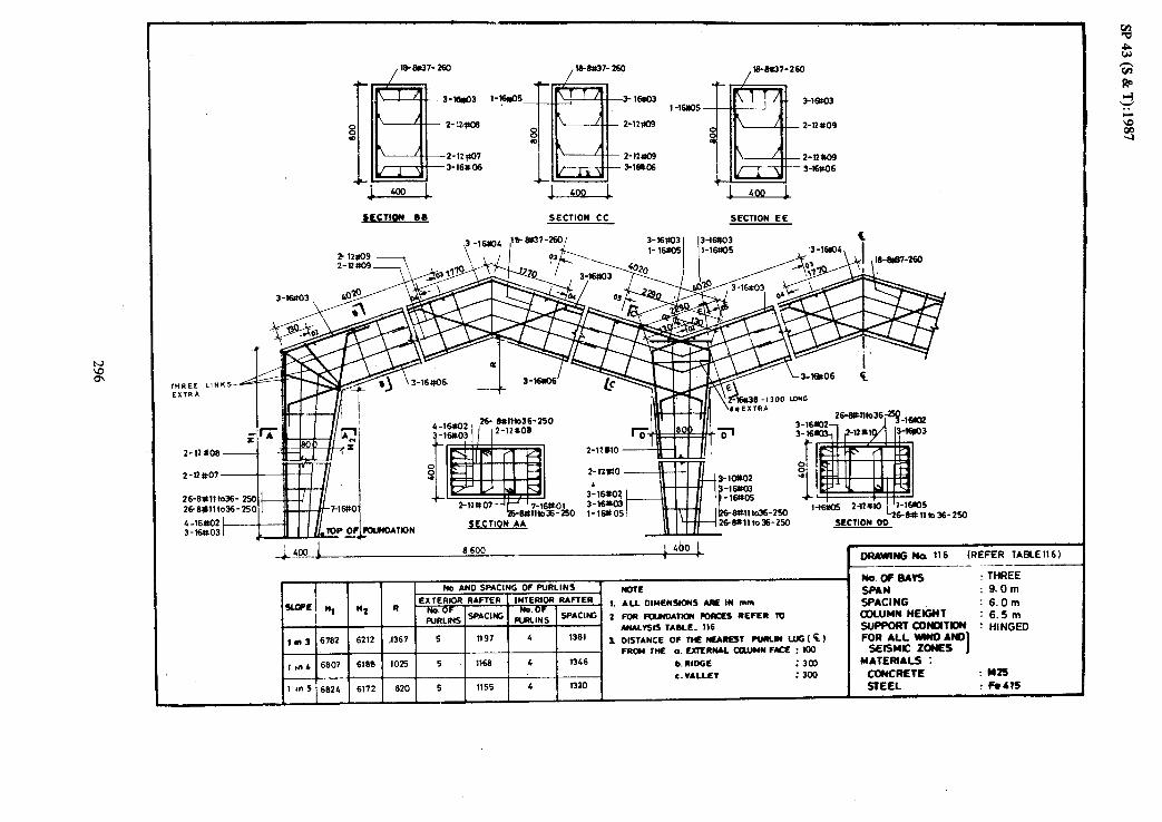
~Eclla4 Be SECTION CC SECTION EE
26-6#111036- 26_6dllto36-
C -16S.02 3-16403 t
1 _.C..n, S%e#37-2601 3-mm3 I IJ-lwO3
.3-lm4,1 /k
(Dlll(o36-250 3 -1ws 3-164
8 600 ~4bo L 1
b. RIDGE
c.VALLET :3w :300
250
OFumnC Na ‘16 (REFER TABLE 116 1 --
No.oF8*K --- : THREE
SPAN : 9.Om
SPACI NC : 6.Om COLUMN HEIGNT : 6.5m StJ- mNo(Tm : HINGED FogRA;: wc&~
1 u*TEm*Ls :
CONCRETE : L(z5
STEEL ! Felts
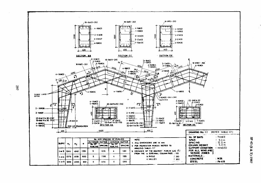
. SltY ; 73315
szw : 3A3Ymo3 : s7*w31*w
s3NOt JlWSl3S QIJV ONlUI 77V UOci
1333NiH : NollloNo3 ModdlK UJO’S : lH9lNI NWITlO3 ~0’21 : 9Nl3VdS WO.6 : NMS 33tlHl : sA*Bdow
OOE : 1317VA'~ 09E : 33aIu xi 001 : 334 NWTW -lvNa3ln ‘0 ml now
(-$I 0ll-l NIlMId 153N*3w 3wl 30 33NVlSIO f LL,-3-levl sIY1vNv
ol Y313Y 53JNQ1 Nol1*0Nllw Nod 2
w”, MI BV SNOISN3WIO l-IV ‘I
_.. ._ ..~ _.--- --- 4
ZODSI-E 00 ~011332 &Z
SceSL-L
3 33 NO11335 33 NO11335 ah40 s
s got191
10# 21
eoXLI-
EOU91-
1 / 09z-we-et

fr. ,ialt 33 NOIL33b iE=d-t
33 NOIl33S
33t!Hl : sAw4o’w -___. -..-
, _ --. ._; .-__. ___ __. ___.__-.a
uJo‘+g: 3N13Vds wl)*g : NVdS
Oili?NlH : \-- -. . .- ___ y1uo)(13modd~
rug’9 : A+?! PKL..
UwDt JWSIK
J

29_8)31-210 I
29-w31-210 /
4-lea03 Z-l6W5 4-16to3 2-16#05 4-16=X
-2-124)e 2-lZscl9 2-null9
Z-12*07
4-16ltO6.
z-12eo9
4 -16806 2-12no9
4-16806
I 1 500 L ‘l-=--L ~tCllON BQ SECTIOW cc SEcnOM EL I
I L5co 1 11500 1 ! 500 DRAWING _~-- No 119 (REFER --- lABLE119)
I
/
Nv.a=eAK THREE : 12.0 m
;. *a. D:YE??S!e4S ‘oc !Y ?II.e
2 FOR mJNMlK*I RJIKES REFER lo AMLIStS TABLE -119
1 DISTANCE OF TN IE*RLSt PuRLIN l.l.6 tE) FRCU WE a. EXTERWL CmJYll f&E : 100
c. VALLEY

I SECTION 18 SECTION CC SECTION EE I
z-12*08 2+ 6#tllto36 - 250
2-12tt.07
26-6dlto36- 250
2~Wfllto36-250 26-(Is11to36-250 SECTION AA 26-Wllto36- 250
D(umNG (lo 120 (REFER TABLE 120) ______-
Iyo. AND SPACING OF WRLINS ’ -.ofMrs : THREE RITE CRLU I
WE n, ’ n2 II CXTLRKW RAFTER INTERIOR RARER
_. -.- : n.nm
- 1. ALL DIYENSIOWS ARE IN mm
klNs SPACING : 6.0m
-*Cl= 2 Foil FWNMltQI RmC?ZS REFER 10 COLUMN liEGrIT ’ AJULVSIS TAME _ 120
lm9 6784 6212 1667 6 1272 6 1145
J. DISTANCE OF TIE NEAmT PlJRIN UG &) FRoLl ME 0. EXllIRML QWUN FYL Kx) : FOR ALL WNO Am 1 SEISMIC ZONES 1 ml 6.909 6166 1400 6 1243 5 1396 b. RIDGE :3M) MAfER(AL!i : 1 Ins C.VALLlV : 300
6825 COncRETE :
6172 1120 wzs
6 1229 5 13 80 !SlELL ! has

ECTION BB SECTION CC SECTION EE
lxx,! I! 500 L 500 1 1 DRAWING No. 121 {REFER TABLE 121)
, No. AN0 SPACLNG OF PURLINS _ NOTE
EXTERIOR RAFTER INTERIOR RAFTER Saw’ NI “2 R thOF I,,,,, No.OF 1
1. ALL DIMENSIONS ARE IN mm .zn.r,..-
1Wl3’9654 9140 1633 6 1295 6 114G 3 DISTANCE OF THE NEAREST PURLIN LUG ($.I
. FROM THE a. EXTERNAL tQuhlfi FACE : KIO
IIn4 9q5 9110 1!75 6 1264 5 1396 b. RIDGE : 300
c.VALLEY : 300 3 ‘RS 9906 9090 1100 6 1250 5 1380
No. OF BAYS : THREE
SPAN : 12.Om
SPACING : 6.Om -1 ,,“U YC,IIYT as WLY”,. ,1&I_ I 1 : .,.-II! UlPPORT CONMTIDN : HINGED FOR ALL WIND AND
SEISMIC ZONES I MATERIALS :
i CONCRETE : H25 ~ STEEL : Fe415 I

w 0 h)
29-W27-210 29-8*27-210 I I p-6W7-210
-l-2am3 ‘3-2004
2-12W7
S-16UO6
2WO4 -2-2OW3
- 2-12809
_ z-12rrg9 -5-l6$06
3-2Olko4 2-2OSO3
2 'ho9
2-12009
5-16rO6
?-2OaO5_ i
320
1 J‘”
11 500 L500 1 1 ORAWING Na (REFER
NaoFBAvs : THREE
c.vALLET Ins 5402 4590 1100 6 1243 5 1365 STEEL : kbl

29-6#2-210
2-12k07
S-16#06
-rr+Tit , \ 8 -_i Q
1B -3-2WO3 3-2OEO4
2-12r(o9
-5-16#06
~CllON l Q SECTION cc SECTION EL I
I// I ,3-2OW3
12_zi+&::: 3-20M3 '
#OI 3-20$Lo4 r A02 _owE? -2oax
____.__. __
/ii I& !l
-- ~ No.*ND SfNCINC Of WRINS
Ho.WeAK : THREE nolL
WC H, N2 I) FLXTERIOR RAflLR 1 INTERIOR RARER
SPA?4 112.0 Ill
no Of m Of s 1. ALL DIYENSK*(S ARE IN mm SPACING : 12.0m
“,i‘m -‘I- ‘W&N5 **Cl* 2 fen fowm411ou mREf twfcR m Wl.UMNtfElGHt : 6.5m
. *WL*SlS TAME- 123 SUPPORlCONUTO(S : HINGED lnt 6651 6140 1633 6 I?465 5 1416 1 OISTANCL Of THE NEAUE)t fURLIN UK; (‘k) FOR ALL WNO AN)
from rtax ~.cxrwt~~auwd fLtl:mo sElsYc ZONES I
(~4 6683 6110 !375 6 1254 5 1361 b. RIDGE : 360 MATERIALS : c. VALLIFT : 300 CONCRETE : M25
llns 69‘3 6090 1100 6 1241 5 1365 REEL : Fe415

SECTION 88 SECllrn cc -- SECTION EE
29-wu-210
1 500 11 500 I so0 1 DRAWING No 124 (REFER TABLE 121)
-.___
No. AND SPACING OF PURLINS NOTE
SLm;, H) ’ w2 R EXTERIOR RAFTER [ INTERIOR RAFTER _ I. ALL OIM~NSIONS ARE IN mm
L $$,Fm SP*ClWG Ido OF ,c,.YILINs .SPAClK. 2 FOR FWNOATICH WRCES REFER TO
I I I I I 4 *WLnIs TABLE -124 1 n 3 9922 9068
-i&l! , en, 9959 9032
rrns 9984 9cm +y/ 1262 i 5 1 1365 1 C.VALLLV : 300
NaoFR4vs : THREE
SPAN : 12.Om
5PACI NC : 12.0m COLUMN HEIGHT : 9.5m SUPPORT CONOITION : HINGED FOR ALL WIN0 AN0
SEISYIC ZONES I MATEFWALS
CaKREtt ,m2s REEL : Fe411

I 3-mu03 3-2CwO2
2-12111
H 2- 12wo
S-IWO9
3-2oa.03 l- zwos 2-ZOnO6 z-11*12
l-&9141034-320
1. ALL OWENSlOWS ARE IN mm 2m -kamoAmm foRcEI REFER To 8 AWLISIS TABLE -125 3. DISTANCE OF THE NEAREST PURLIN L”Gt%)
FRCU THE a. EXTERNAL CClllMN FACE : 100 b. RIDGE : 300 c.VALLEV : 300
DRAWING No 125 (REFER TABLE 125) ___ ___._._~_ _~~
No. OF BAVS . THREE
SPAN : lE.Om SPACI NC : 6.0m COLUMN HElGtiT : 6.5m SUPPORT CONCMTION : HINGED FOR ALL WlND ANQ
SEISMtC ZONES 1 MATERIALS :
CONCRETE : I425 STEEL : Fe415

2-2OaO3 -3-2OttO4
SECTION LE
2-2aw2 2-2WO3 _ 32wO4
2-2WtO3 3-20*)6
2-12rtl6
2-1216
3-2OM3
3-2&%i 7_1cu, 30-81116th7-320
SECTION AA
6
30011
17 500 1 600 1 1 ORAWIMG Ma 126 (REFER TABLE i26)
No.oFGAK : THREE
SPAN : 18.0m
SPACING : 6.nm COLUMN HElGHf : 9.5m S&PF’ORlC0NoIT~ : HINGED FOR ALL WIN0 AN0
SEISMIC ZONES I hwEm*Ls : CoNCAElc : Yzs STEEL ! ro4n
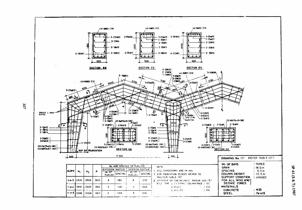
I 41 m3- 210 44-BOB3 210 44-W3-210
I 3 25W3 - 3-251105
2- 12m4 -l-2%07
ml p---q- 2-lt+15
i l--=-L L w.3 i
SECTION Bk’ SECTION CC 3-2511051
SECTION EE
Z-2*6-, 2-12sl6, 1
,2&5/Z-12,tl6 33 BnsOa82- 80 --
SECTION 00
DRAWING No. ‘27 (REFER TABLE 127)
No AND SPACING OF FURLiNS . NO. Of BAYS : THREE
NOTE SPAN : 18Om
SLOPE1 n, Ii:, R i. ALL D$%E%S!ONS ARE IN mm SPACING : 6.0m 2 WR KMdXTI~ON FCQCES REFER TO COLUMN HEIGHT : 12.5m
-------I? J&ii\:515 l&t)LE -127 SUPPORT CONMTION : HINGED
In3 12924 12068 2800 8 1 1270 j ! 3 3!:>Ta%CE OF IHC NEAR&T P”RL,N LUG {‘ii) FOR ALL WIND AND
/ 1240 i
i=;..;,,, !HE 0 e.0 Q:i4L CUUMY FACE : 130 SEISMIC ZONES I 1 ,nL 12961 12032 2K)o 8 b RIJr>:- : 300 MATERIALS :
9 1225 i
c i’Lii..F\ : 3% CONCRETE : M25
1 In 5 12986 12008 1680 .3 1 1346 / STEEL : Fe415 ~- . *_ ____ _: __... .:. _.._ _-_-_-___

z- 2-03
3- 2lmo9
3-25402
z-l2ull
Z-12UlD
3-251103 q oaus
- 2-1*12
__2-12rt12
- 3-2y1)3 + 3-25tro6
- 2-12:lz
- 2-12&J
>ECllon 08 SECTION cc ,L2-2 I,--2 3
&-e850-?10 2-2Fsra _*E3 lzi
No. AND SPACING OF PL’RL;S
l ALL GlMENSI@iS AHE IN mm
DRAWING No. 128 (REFER lABLE128)
No. OF BAYS : THREE
SPAN :lB.Om SPACING : 12. 0 m COLUMN HEIGMT : 5.5m SUPPORT CONDITION : HINGED FOR ALL WIND AND
SEISMK ZONES I MATERIALS :
CONCRETE : M25
STEEL

__ 2-11*12 I
2-12*13
2%6#l61040 -36 -25 c 25-604lto65- I
-259 -25s
SLcTIom EC 2-12#14 \ 1,2-12#14
--- I
,25-9W6b40 -380
1 I25-08A1le65-360
i 25-~b40-3iO 2b384lla65- 360
1500 1 (REFER TABLE 129)
rb. Am0 SPACING OF NRLlNS
WE n, n2 II EXTERIOR RAFTER i INTERIOR RAmER .
,mS 9922 9066 2800 6 1366 8 1225
1.
2
1
mTE
ALL OIYERYOIS H IY mm
fmmmoAnaCDllQIRtNR1ID AWL1515 TULE -129 08STANCE Of TN RIBREST PUUW LUG(k) fRoMwE 0.u7ERMLmiJwMHft:nx,
c. RIDGE :360 1 1 I 1 I I I
c.VALLEV : 1mS -
5SO 9964 9008 1660 8 1339 7 1376
MmoFM*5 : THREE
Sp*M : iaom SPACI NC : l2.0 m oDun*r Iwail : 9.5m
: HIWED
UATEHALS : : Mb
SmEL ! k4A

/ .K+BC52- 210 438#52- 210 / /
43-8052-210
A---L---- 3- a03 3-25 ia06
3-25004 I- 2%04 1-25M4
2-12#16 1-25~07 2-12 t117 l-25*07
2-tZul5 2-12 a7
2- 12eJ.4 2-12 ‘917
SECTION cc SECTION EE
L,an52- 210
i
‘ACING OF PURLINS , NOTE a RAFTER 1. ALL OIMENSIOWS ARE IN mm
_.._& SPAC’* 2 FOR FwNDATIcN FORCES REFER TO I
’ I 1225 ANALYSIS TABLE _ 130
3 DISTANCE OF TN NEAR=1 PURLIN IJJG tq, !e 1 FROM THE CUIMN FACE : lfi
1m4 13074 11915 2063 8 1377 7 1395 a. EXTERWL
b. RIDGE : 360
1 InS c.VALLEY : 550 13~)s 116&5 1650
6 1362 7 a70
DRAWING No 130 (REFER lABLEl30)
No. DF BAYS : THREE
SPAN : 18.0 m
SPACI NC : 12.0 m COLUMN HEIGHT : 12.5 m SUPPORT CDNMTIDN : HINGED
FOR ALL WIND AND SEISMIC ZONES I
MATERIALS : CONCRETE : H2s STEEL : Fe415

SECTION- CC SECTION -‘EE SECTION - FF
60
2 -12so9
3-l-6
2-l61u2 -130 LONG
1 _” -..-.,
LOO! 250. zo-silliao-290
1 I
4a@ 66w 6600 400
lo
I DRAWING NO. 131 (REFER raeLEl3i)
r I I I No. AND SPACING OF PURLINS 1 ll”TC t No. OF BAYS : FOUR SPAN : 9.0m SPACING : 6.Om COLUMN HEIGHT : 5.Om
SUPPORT CONDITION : HINGED FOR AU WIND AND
SEISMIC ZONES I MATERIALS :
CONCRETE : M25 STEEL : Fe415

60
I-Hyo5
z-lZW9
2-llqlO9
3-16W.O 6
,lkW137-260
2-12@09
,18-W7-2’3l
- l-W&05
2-12909
2-lwO9
SECTION - BB SECTION- CC SECTION -‘EE SECTION - FF
No. AN0 SPACING OF PURLINS
SLOPE n, Ii2 R EXTERIOR RAFTER 1 INTERIOR RAFTER
$iLES SPACING
11” 3 6782 6212 1367 5 1197 4 1381
1 en 4 6907 6169 I 1025 5 1 1166 4 1346
NOTE
1. ALL OlMENSlONS ARE IN mm
2. FOR RXINOATION FORCES REFER TO ANALYSIS TABLE-132
c.VALLEY
-’ No. OF BAYS :FOUR SPAN : @.Om SPACING : 6.0m COLUMN HEIGHT : 6.5m
SUPPORT CONMTION : HINGED FOR AU WIND AND
SEISMIC ZONES
1 I
MATERIALS :
3. DISTANCE OF THE NEAREST PURLH LlG(E)
FROM THE a.EXTERiJAL COLUMN FACE I 100
b. RiOtE : 300
A
DRAWING No. 132 (REFfiR lABLE132)

w c w
_ZFCTlON - B &
1-I 6NJ5
WWl-260
L-SW3
2-nm9
2-KM9 cmm6
SECTfc?ti- cc ,
l-16&5
SECTION -‘EE
2-12 a09
t-lZm9 - 4-WI06
SECTION - FF
YI 111
SECTION-AA
6600 boo 8600
SECTION-OD 1 460 1
.I_, “I‘WW .--
20-wno30 -250
SECflON-GG
OffAWING NO. 133 (‘REFER TABLET:
’ No.OFBAVS :Rx# -__ _.
1. AU OlMEMSlW ARE IN mm
2. i01 IWwD*nac rORCf% nffts 70 AWALISIS TABLE - 133
1 061Awx of TnE Nti4mfST RJRLH LUG CC) FROM= a.EAiEiWALGLUWn ?*Q I 100
b. RIDGE : 360 r.vAutv : 3co
5FAN : S.Cm SPAUNG : 12.Om cOwuN HEIGHT : 5.0m
!zt%Joa~;~~ : HliGEe
SEISMC ZONES J MATERIALS :
CorcREtE : M25
St= : Fe 415

l-16605- c-16#JJ
2-12*9
2-12009 1-16+06
SECTION -‘EE
19-897-260
l-16*5 6m.03
2-12*09
242nl9 Cl6UO6
SECTION - FF
ORAWING No. 13& (REFER TABLE1341
NO. AN0 SPACING OF PLJRLINS NOTE A No. OF BAYS : FCUR
-r* nz R EnERIoa RAFIER INTERIOR RAfTER SPAN : 9.0m
g$& SPACNG 1. ALL DIMENSIONS ARE’IN mm
p$& spAC’NC 2. f0R FWNDAllffl FORWS REFLR TO SPACING : 12.0 m COLUMN HEIGHT : 6.Sm
ln3 6M9 i61LO ANALVSIS TABLE _ 134
1333 S 1212 4 1361 SUPPORT CONDlflON : HINGED 3. DISTANCE OF THE MUREST PURLN LUG (‘$1 FOR ALL WIND AND
lm4 wm 6110 IO00 5 1163 ‘4 t326 FROM THE o.EXTERNAL CCUJMN FACE I 100 SELSMIC ZONES I
b. RIDGE : 360 MATERIALS : c.VAULV
tmS 69op 6090 MO S 1170 4 . 13x) : 300 CONCRETE : M25
STEEL : Fe415
--

2-16~~05 4-16#03 ~2-16005 z-16*05 c-16#03
2-12 I+09 z-12tto9
2-12w306 2-l/p09 4-1406 4-lW6 4-lEfto6 4-16~06
_j__sm-&
SECTICN - BB SECTION- CC SECTION --EE SECTION - FF
20-Wllto30 -250 1
(I!!+ I 8
2O+MlhdO-250
-4-u- - .----7 2O-Wm30-250 SECTION-DD 2~*1,,030_250
2O+l11o30-250
DRAWING No. 135 (REFER TABLE1351
No. AND SPACIW OF PURLINS
SLOPE / H, H2 EXTERIOR RAFTER INTERIOR RAFTER
/ I /
R
&j;S SPACNG zRLzS SPACING
11’3 is282 i 4712 1867 6 1273 6 1145
1 I” 4 I5307 4688 1400 6 1243 5 1396 I
1 m 5 5324 4672 1120 6 1230 5 1380
NOTE
1. ALL DlMENSlONS AR ‘IN mm
2. R)R IDJNDATIGN FCRCES REFER TO ANALYSIS TABLE -135
3. DISTANCE OF THE NEAREST PURLIN LUG (‘$)
FROM THE a. EXTERNAL COLUMN FACE ! 100
b. RIDGE :300 c.VALLEV
: 300
No. OF BAYS : FOUR SPAN : 12.Om SPACING : 6.0m COLUMN HEIGHT : 5.Om SUPPORT CONDITION HINGED FOR ALL WIND AND
SEISMIC ZONES 1 i MATERIALS :
CONCRETE : M25 STEEL : Fe 415

t 4-16tlO3
8
1
t 12406
m
2-12+07 ClW6
29-M7-2D
/ 29-8#37-210 ,2+6@7-210
2-let05 .&_16Roj .1m5 If7 4-16803 z-16QO5 4-16X33
.2-12tcl9 2-12809 8 0
z-12109 h-w06 c16ilO6
SECTION - 0 0 SECTION- CC SECTION -‘EE SECTION -FF
26-6&36-250
SECTION-GG I
500 : 11500_ I son 1 ll500 I’.-- --w 5&l SECTION- AA
- No AND SPACIffi OF PURLINS NOTE EXTERIOR RAFTER SLOPE ‘4 M2 R _ INTERIOR RAFTER - 1. ALL OIHENSIONS ARE’IN mm
ERRLoINF5 SPACM 2. mR FOUNDATION FORCES REFER 70
ANALYSIS TABLE-136 tan 3 , 6764 6212 1867 6 1272
I 3. OISTANCt OF THE NEAREST PURLIN LUG cc)
FROM WE n. EXTERNAL COLUMN FACE I 100 1 rn L 6803 6186 1400 6 1243
b RIDGE : 300 r.VALLEI : 300
tnS 6625 6172 1120 6 12 29
r-NG p(o. 136 (REFER TABLE136)
No. OF BAYS : FWR SPAN : 12.Om SPACING : 6.0m COLUMN HEIGHT : 6.5m
SUPPORT CONOlTlON : HINGED FOR AU WIND AND
SEISMIC ZONES I MATERIALS :
CONCRETE : M25 STEEL : Fe415

‘)-2CW6 I-2ollOs
2-12all 2-l2m1
2-121111
SECTION - b 0 SECTION- CC SECTION -‘EE SECTION - FF
I I xl-&Lj3tc42 -320 II I 3&W3tc42-3X
DRAWING No. 137 (REFER TABLE 137)
No. AND SPACII’G OF PURLINS
SLOPE nl Ii2 R EXTERIOR RAFTER 1 INTERIOR RAFTER
;iLcs 1 SPACNC 1 EL$ 1 SPACING
lm3 ! 96~4 j 9140 / 1633 1 6 1 1295 1 6 1 “4s 1 I I I I I I I
10” 4 9865 9110 137s 6 1264 .S 1396
I I I I I I I 1ns 9906 9090 1100 6 12SO 5 1360
NOTE
1. ALL OlHENSlONS ARE IN mm
2. F[)R FWNDATION FORCES REFER TO
ANALYSIS TABLE-137
1. DISTANCE OF THE NEAREST PURLN LUG (Q
FROM THE a. EXTERNAL COLUMN FACE ,100
b. RIDGE : 3al c.VALLEV : : 3ljO
No. OF BAYS : FOUR SPAN : 12.0 m SPACING : 6.0m
COLUMN HEIGHT : 9.5m
SUPPORT CONMTION : HINGED FOR AU WIND AND
SEISMIC ZONES I MATERIALS :
CONCRETE : M25 STEEL : Fe415

2-12*07
SECTION - 8 0 SECTION- CC
3-2fXI4
f
S-16ttO6 I
SECTION -‘EE
3-20#4
SECTION - FF
16-&11C26-3x) kMo26-320
f
l-24102 3-203 f2QtO4
t6-ewb2c32o 16-8ttllto26- 320
166*11$26’-320
J_soo
,20*2 .2oaO3 2oRO4 t Es!' zMo& r
500 11 500 15-&ttlto26-320 320
I MAWING N~J. 138 IRE6ER lABLEl36B)
I No. AND SPACING OF PURLINS
SL’)PE Y( tt2 R EXTERlOR RAFTER INTERIOR RAFTER
&L~s SPACNG GLES SPACING
11n 3 5348 4640 1833 6 1287 5 1416
1 I” L 5360 4690 1375 6 1257 5 1361
1ms 5402 4590 1100 6 1243 5 1365
NOTE
1. ALL OWENSIONS ARE IN mm
2. R)R FWNOATION FORCES REFER 10 ANALYSIS TABLE.. 138
3. DISTANCE OF WE NEAREST PURLVt LUG (El FROM TNE a. EXTERtiAL COLUMN FACE , 100
b. RIDGE :361) c.VAUEV : 300
No. OF BAYS :fUJR SPAN : 12.0m SPACING : lZ.Om COLUMN HEIGHT : 5.Om
SUPPORT CONMTION : HINGE0 FOR AU WIND AND
SEi!%lC ZONES I MATERIALS : -
CONCRETE : M25 STEEL : Fe415

- --
-i--Q--l 1 500 1
SECTION- CC SECTION -‘EE SECTION - FF
I IL fY 1- w?vJ- I .-.
2l*llto 31-320
3 w E
rJ_r_yL r-‘-T I
SECTION-AA
21-f~WtcJl-320 SECTION- GG
t 11600 lSOO1 11 SO0 1 s&l 1 21-64Hlfo31-320
i_ 21-Wlto31-320
mAWING No. 139 (REFER TABLE 139)
1.
2.
I
NOTE
ALL DIMENSIONS ARE IN mm
m IouNDAnow fW?CES REFER TO ANALYSIS TABLE -139
DLSTANCE OF THE NEAREST RlRN LUC (c: FROM WE a. EXTERi4AL COLUMN FACE I 100
b. RIDGE :360 c.VAUEV :300
No. OF BAYS
SPAN SPACING COLUMN HEIGHT SUPPORT CONDITION FDR ALL WIND AND
SEISMIC ZONES I MATERIALS :
CONCRETE STEEL
: FOUR : 12.Om : 12.0 m : 6.5m : HINGED
: M25
: Fe415

2-lWJ7 6-16ttO6
‘L ‘l-.=--A SFCTION - b & SECTION- CC
2-2cntOs
2-l?UlO
2-2CUO5
2-12 WI-
1 500 1 ‘-l---d SECTION -XE SECTION - FF
Z-2005 L-2m3
2-l?WO
2-12n10
.6-16#06
MO. AJm SPACING OF PURLINS
R ExlERloaR*FlER
i%%S sPACw;
INlERIoa RAFTER (.
ZL:, %xw'~ z.
1600 6 1306 5 1416 a
1350 6 1276 5 1301
1oao 6 1262 5 1365
DRAWING No. I40 (REFER TABLElLOl
No.OFBAVS :RxlR SPAN : 12.0 m SPACING : 12.0 m COLUMN MEtGnl : 9.5m S$Wd$Nys : HWGEO
SEISMIC toNcls J MATERIALS !
aMmETE : M25, : Fe41$

kP 43 (S &
T): 1987
_--
321

SP 43 (S & T): 1987
WINDWARD SIDE
EXTERNAL
PRESSURE’
(VARIES WtTH ROOF SLOPE I
WLy-WIND PERPENDICULAR TO RIDGE WITH INTERNAL SUCTION
WINDWARD StDE
EXTERNAL
PRESSURE
(VARIEti WITH ROOF SLOPE )
-
o*sp. -
4
c -c
C +o.zp + *
f --c
--c
- o*sp
+
WL2-WIND PERPENDICULAR TO R@GE WITH INTERNAL PRESSURE
+0*2p
p-BASIC WIND
PRESSURE
WL3-WIND PARALLEL TO RtDGE WITH INTERNAL PRESSURE
DRG. 142 WIND LOAD ON PORTAL FRqMES
322
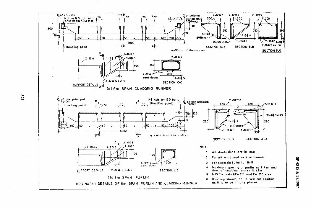
Handling point SECTION A-A SECTION 8.8 Z-16*6 extra
a=Width of the column SECTION D-0
I 2-12%2
\2 -120 6 extra
SUPPORT DETAIL! 5-l
Bn (a) 6m SPAN CLADDING RUNNER
SECTION C-C
140 hole for 12 $ bolt,
a =Width of the rafter
SECTION B-B SECTION A_A
SUPPORT DETAILS 2 -lZ++ 6 extra SECTION C-C
(b) 6m SPAN PURLIN
DRG.No.lL3 DETAILS OF 6171 SPAN PURLIN AND CLADDlNG RUNNER
4 Maximum spacing of purlin IS 1.4m and that of cladding runner is 1.7m
5 M25 Concrete&Fe 415 ‘and Fe 250 steel
6 Handling should be in vertical position as it 1s to be finally placed
__._. -
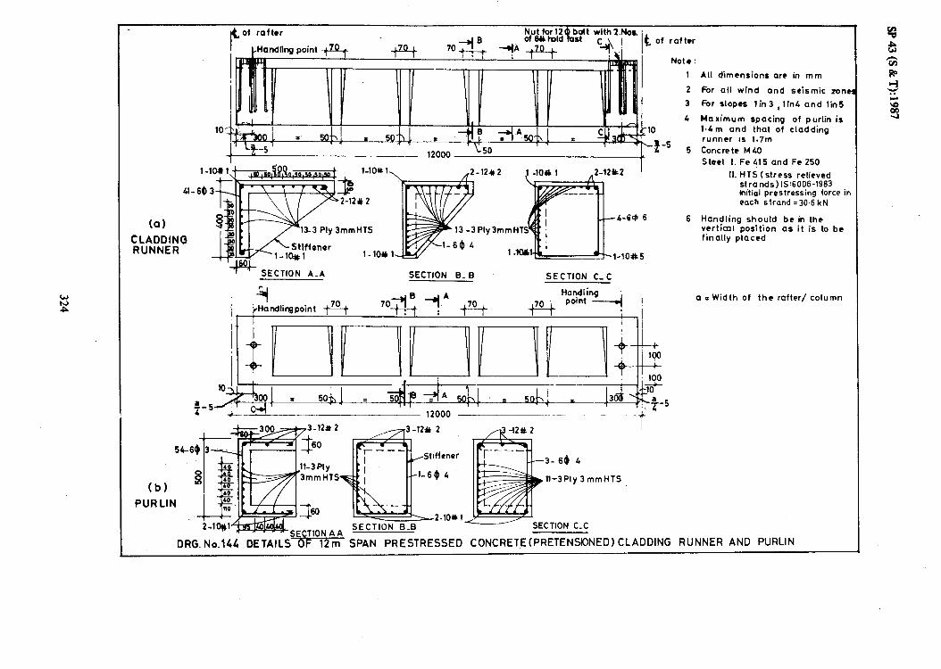
4. of rafter
CHandflng point I k of rafter
Note:
1 All dimensions are in mm
1 ILUUU _.
f
2 For all wind and seismic lonet
3 For slopes lin3 ,lin4 and lin5
4 Maximum spacing of purlin is 1.4m and that of cladding runner Is 1.7m
5 Concrete MC0
Steel I. Fe 415 and Fe 250
II. HTS (stress relieved strands) lS:6006-1983 lnitiol prestressing force in each strand =30.6 kN
!iffenor 1
++- SECTION A_A SECTION B_ B SECTION C_ C
;I +tandliqpoint * 1
(b)
PUR LIN
y 3mmHTS
c_c
DRG. No.144 DETAILS OF 12m SPAN PRESTRESSED CONCRETE(PRETENSlDNED) CLP -
!
I, t
loo I+ 100
, k iii+-
= 5 ; i-
rDDl ING RUNNER AND PURLIN
6 Handling should be in the vertical position as it is to be finally placed
a = Width of the rafter/ column

ti20 ,140 hole for 124 bolt ,
SECTION A-A
(a) For 6m Span Purlin
20
\\,A4 DRG No.145 FIXING DETAILS FOR PURLIN
LUG DETAILS
LUG DETAILS

8 8 holdtart welded
I SIDE VIEW
I SECTION A- A
(Showing holdfast detail&j (a) FOR 6-DM SPAN
uco- SIDE VIEW
n I” 1
ZNoc ottO# holdfort welded N!& /fto M.S.Plot@
Y .s. Plot. 12040.12
,-ISA 60~6096
+loddii bnner
et ldfost nut
SECTION B- B
(b) FOR 12-O M SPAN
G.I. Flat washe-, Bitumen woshef __
I BRACKET DETAIL
n
I:’ 2-O# Links
/ 3-M+
SHEET CONNECTON
6.1. Nut-----------_,
BRA&ET DETAIL
G.1. Flat worher, Bitumen washer
I
A.C.ShWw
L- 3-8s L nllr !
__X_t
SHEET CONNECTION
DRG. ~0.146 FIXING DETAILS OF CLADDING RUNNERS
I

f
I ;;I
P
.
__.-
.-.-
.
L86
I :(1
0 S)
Et
dS

po*1*1-20#2 r2- 20# 1
++
f I ff--j.. !
w G-+.1-2oil2 I - ~32ameo bA 2-20#1
) 13w 1
d!BA
Column
2-25*1 SECTION A A
SECTION A A
(a) CAST - IN - SITU
SECTION B B
DETAIL P
(b) PRECAST (i) FOR 6.0 M SPAN
ORG. No. iP8
(a) CAST - IN- SITU _A--_ 12000 t
I
I I
:;b’,“., _~‘Iu u 1 i M.S.,Plate 3LOm5~Om12 ?I
DETAIL P
(b) PRECAST (ii) FOR 12.0 M SPAN
DETAILS OF EAVES BEAMS

sP 43 (S & T):1987
/--6*ST Cm + d/L
D, WHICHEVER GREATER (i3 * 100mm
H/G OR D,WHIf?HEVER GREATER $1 B#ST tab P 100mm
.-TOP OF FOUNDATION
ST =STIRRUPS
d =EFFECTIVE DEPTH OF SECTION
Ldt=DEVELOPMENT LENGTH IN TENSION
DRG. No.149 TYPICAL DETAILING FOR DUCTILITY REQUIREMENT
329

0 1 INDICATES HOLE FOR TRANSPORTATION
0 2 INDICATES HOLE FOR ERECTION
FOR DISTANCES ‘a’ AND ‘b’ REFER TABLE NO. 141
TOP OF FOUNDATION OP OF FOUNDATION
ORG. No.150 LOCATION OF JOINTS AND LIFTING POINTS DURING TRANSPORTATION AND ERECTION

0 M LIFTING EYE *
P 0
,
4’ ..
.,’
(’ v
LIFTING EYES AND CAST IN STUDS
DRG. No. 151
PIN
STUD
LIFTING EYE
SP 43 (S & T): 1987
/ P
SINGLE OR _
I 4 .’ -; I 6 :_
‘. _‘. ,-
-+-
--
:/ crl .-- . ‘6 I / .‘i . ‘.,
I :“I ‘. I l
‘:: i .
‘.
*., i .;, ‘;. 1 ; ;. . .
. ,
. .
‘. I I : .I, :. . 1 I ;:j I.‘d .: 1 I
1 : 1 1 .,, . ’ I
.:‘I 1 ,;;.; f 1
‘. I I - ( ‘Q.___
A MECHANICAL
CONNECTION GIVES
AN ADDED SAFETY
IN SLENDER UNITS
SCHEMATIC DETAILS OF FIXTURES FOR HANDLING PRECAST MEMBERS
331

SP 43 (S &T):1987
1 800 1
PRECAST COLUMN
-lo-12#6
-lo-t2# 5
M-12 #4
-CEMENT MORTAR 1~3
L--12-12*2 42-12 #l ! i
3125 1
LEAN CONCRETE 1 T
ELEVATION . .
PLAN
a) FIXED BASE
DRG.152 DETAILS FOR PRECAST COLUMN AND CAST-IN-SITU
FOUNDATION (CONTO.)
332

SP 43 (S & T): 1987
LEAN
CEMENT MORTAR GROUT
12-8#5-----__
CONCRETE
4-1 cl#4-
: Q w
ORG. 152
9-lO#l J L9-10#1 1600 I
-.
-
-,
ELEVATION
4-10#3
I
L
-l6-10#2
/
9-lO#F/ .
I 1600 I I
PLAN I
b) HINGED BASE
DETAILS FOR PRECAST COLUMN AN0 CAST-IN-SITU FOUNUATION
-9-lO#l
333

M.S.rod woldod to
Bats Lap welded In-situ concrrb M 25
Cohn
BEFORE ASSEMBLY
dta
mnmI mortar 1:3
VIEW FROM TOP AFTER ASSEMBLY
TYPE 1 (Refer Table No.%2 )
Bars Lop welded
of mftor
SECTION A- A
TYPE 2
DRG. No. 153 TYPICAL CONNECTION &TAILS IN A RAFTER

CLADDING - RUNNERS
RAF.TER BRACING IN THE END BAY-
RAFTER BRACING IN THE
INTERMEDIATE BAY
i
OLUMNS
I
I I I VERTICAL BRACING IN END BAY
ABLE END COLUMNS
DRG. No.154 SCHEMATIC ARRANGEMENT OF BRACING

!8’43(S&T):1987
COLUMN
ISA 50X513X6 SA 50X50X6
DETAIL P
SECTION A A
7
-/ \
f -,
400
AAr
COLUMN
.-- 6000 1
(a) STEEL BRACING
DRG. No.155 DETAILS OF BRACING (CONTII
336

SP43(S&T):1987
F@- t
COLUMN
/ jvy-
0 I u?
-
Q (@ 150
-2O#
i 150 c
LOO I 1
6000
COLUMN
I
(b) RCC BRACING
FIG. 155 DETAILS OF BRACING (CON’ID.1
337

SP43(S&T):1987
S. PLATE 150X70X10
R.C.CI COLUMN
GUSSET
ELEVATION
ISA 50X50X6
PLAN
DETAIL P
TO BACK 6
DRG. 155 DETAILS OF BRACING (CONiD.,
338

SP 43 (S 8K T): 1987
-
-M.S. PLATE 150X50X10
.S. PLATE 150X150X10
ELEVATION.
PLAN
DETAIL R
DRG.155 DETAILS OF BRACING (CONlO.)
339
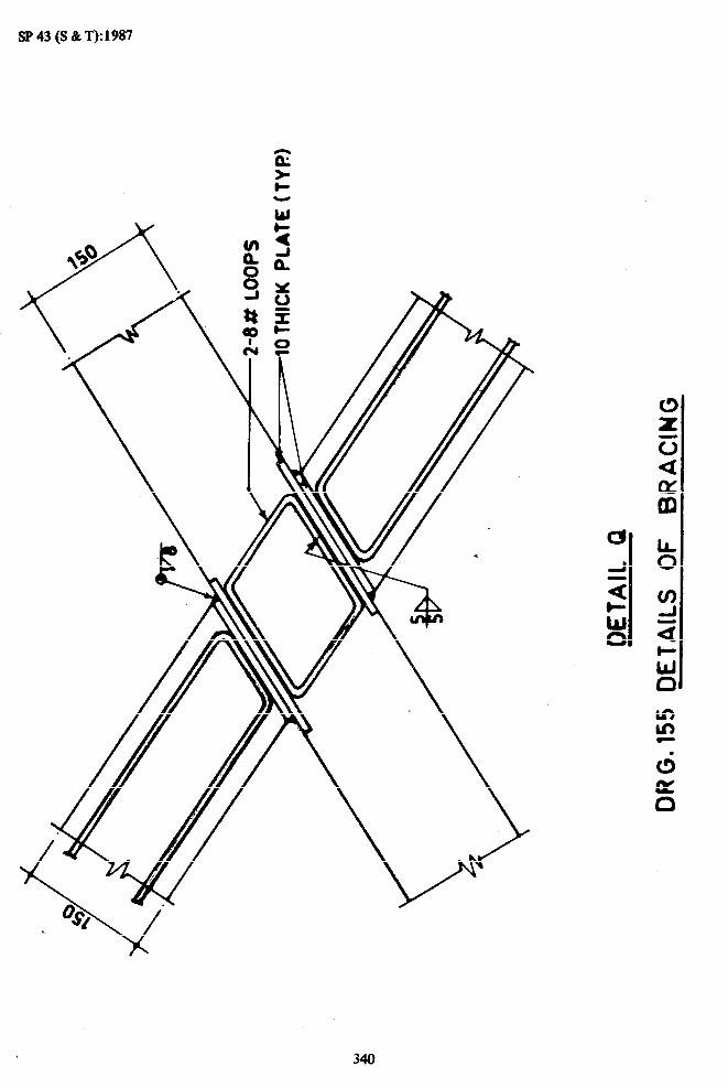
SP43(S&T):1987
340

SP 43 (S & T):1987
ELEVATION
12-12s 27
LLEAN CONCRETE
2300
PLAN CO) FOR FIXED BASE (FOR omm4 REFER CLAUS 6.5.1 1
f3RG. 156 FOUNDATION DETAILS FOR CAST- IN-SITU COLUMN
341

SP 43 (S & T): 1987
1 1600 9-10 a 1’
1 CLEAN
ELEVATION I
P4-lO#l plO#l
/-6%~@3 (,,a#2
I 1 500 1
I 600 i _ 1
PLAN
CONCRE
(b)sFOR HINGE0 BASE
(FOR DESIGN REFER CLAUSE
6.5.3.1) I
DRG. No. 156 FOUNDATION DETAILS FOR CAST-IN-SITU COLUMN
342


