SOYAL Protocol... · 2020-01-01 · Description of Data Bit : 20 . AR721E Status : Neither card nor...
37
SOYAL TECHNOLOGY CO., LTD. http://www.soyal.com 2018/10/5 Page 1 / Total 37 pages SOYAL Communication Protocol Item No. AR-721E Version 1.X Author Andrew Shih Date October 5, 2018
Transcript of SOYAL Protocol... · 2020-01-01 · Description of Data Bit : 20 . AR721E Status : Neither card nor...

SOYAL TECHNOLOGY CO., LTD. http://www.soyal.com 2018/10/5
Page 1 / Total 37 pages
SOYAL
Communication Protocol
Item No. AR-721E Version 1.X
Author Andrew Shih
Date October 5, 2018

SOYAL TECHNOLOGY CO., LTD. http://www.soyal.com 2018/10/5
Page 2 / Total 37 pages
Index Page 1 Communication Protocol …………………………………………………… 4
1.1 Preparing Connect ……………………………………………………………………………. 4 1.2 Data Format …………………………………………………………………………………… 4 1.3 Data Packet …………………………………………………………………………………… 4 1.4 Echo Code ……………………………………………………………………………….…… 5
2 Command List ………………………………………………………………… 6 2.1 Operation Mode ……………………………………………………………………………… 6
2.1.1 18H: Get Device Status (Event Polling) …………………………………………………… 7 2.1.2 Device Status Define ………………………………………………………………… 8
2.2 04H: Prompt Accepted Message ………………………………………………………………… 11 2.3 05H: Prompt Error Message ………………………………………………………………… 12 2.4 09H: Prompt Keying-in Password ………………………………………………………………… 13 2.5 20H: Write EEPROM ……………………………………………………………………………… 14 2.6 12H: Read EEPROM ……………………………………………………………………………… 15 2.7 21H: Relay Control ………………………………………………………………………… 16
2.7.1 Relay Control parameters …………………………………………………….…………… 16 2.8 23H: Write Real Time Clock (RTC) ……………………………………………………………..…… 18 2.9 24H: Read Real Time Clock ………………………………………………………………………… 19 2.10 27H: Set Text of LCD Display ………………………………………………………………………… 20 2.11 25H: Get the lasted event log of Device …………………………………………………… 21
2.11.1 Message Events ………………………………………………………………… 21 2.11.2 Message Sources ………………………………………………………………… 21 2.11.3 Duty key value ………………………………………………………………… 21
2.12 37H: Delete the last Transaction ………………………………………………………………… 22 2.13 2DH: Empty Device Transaction queue ………………………………………………………… 22 2.14 30H: Displaying bitmap Patten onto LCD ………………………….……………………………… 23 2.15 31H: Mifare Complex Command …………………………………..……………………………….. 24 2.16 80H: Set Node ID ………………………………………………….…………………………… 25 2.17 81H: Reset Device ……... …………………………………………….………………………… 25 2.18 82H: Set Duty Code (Time & Attendance) …………………………………………………………… 26 2.19 83H: Set User Data ………………………………………………………………………… 26 2.20 87H: Get User Data ……………………………………………………………… ………… 26 2.21 84H: Stopping Waiting for Response ………………………………………………………… 27 2.22 85H: Empty all Users ……………………………………………………………… … 28 2.23 86H: Reset Anti-pass-back ……………………………………………………………………… 29 2.24 2AH: Set Time Zone …………………………………………………………..…………… 30
2.24.1 Auto-shift Setup …………………………………………………………….………… 30

SOYAL TECHNOLOGY CO., LTD. http://www.soyal.com 2018/10/5
Page 3 / Total 37 pages
2.25 2CH: Set Holidays ………………………………………………………………..………….… 31 2.26 88H Set Extend Parameter ………………………………………………………………………. 32
3 Data Structure …………………………………………………....................... 33
3.1 Data Structure of Users ………………………………………………………………………….. 33 3.2 Data Structure of Time Zone ……………………………………………………………………… 34 3.3 Data Structure of Holidays ………………………………………………………………………… 35 3.4 Data Structure of Anti-pass-back ………………………………………………………………..… 36 3.5 Memory Layout of AR-721E ……………..………………………………………………………… 37

SOYAL TECHNOLOGY CO., LTD. http://www.soyal.com 2018/10/5
Page 4 / Total 37 pages
1 Communication Protocol All SOYAL® devices use the same protocol, only the commands given vary depending on different devices
1.1 Preparing Connect: Prior to connection to AR-721H, the node number of the device has to be known. The node number could be checked from the keypad as shown on the table below:
Steps AR-721H AR-727H Step 1:(Enter into EDIT MODE) * 1 2 3 4 5 6 # * 1 2 3 4 5 6 # Step 2:(Setting Node ID) 0 0 * 0 0 1 # 3 → 1 → 1 # Step 3:(Exit) * # * * * #
1.2 Data Format : Baud Rate 9600,N,8,1
Data Format Binary HEX Data Data Packet
Head Length Destination ID Command Code Data … XOR SUM
8bits 8bits 8bits 8bits 8bits 8bits
1.3 Data packed : Size
(Byte) Description XOR
0xFF SUM 0x00
Head 1 0x7E No No Length 1 Data Length Indicator which denotes the length
from Destination to the end including XOR and SUM
No No
Destination ID
1 Destination Node ID 00: Reserved for the bus master FF: Broadcast to each reader
Yes Yes
Command Code
1 Instruction Command Yes Yes
Data 00
~ D0
Length of Data Block which varies depending on instructions
Yes Yes
XOR 1 To XOR each byte from Destination ID to Data with 0xFF
Yes
SUM 1 TO sum each byte from Destination to XOR with 0x00. If the summary is greater than 0xFF, it should keep the low byte.
Example:Polling Status from Node. 1 Head Length Destination Command Data … XOR SUM 0x7E 0x04 0x01 0x18 0xE6 0xFF
XOR = 0xFF ^ 0x01 ^ 0x18 = 0xE6 SUM = 0x01 + 0x18 + 0xE6 = 0xFF Node ID needs to set from the keypad。Please refer to the command list for- 00*

SOYAL TECHNOLOGY CO., LTD. http://www.soyal.com 2018/10/5
Page 5 / Total 37 pages
1.4 Echo Code :
Command Description Note
03h Echo requested data 7E xx 00 03 [Data... ] XOR SUM
04h Echo command acknowledged (ACK) Note:1 7E 04 00 04 SID RDR ... FB FF
05h Echo command unacknowledged (NACK) Note:1 7E 04 00 05 FA FF
06h Echo authentication failed (AUTHERR) 7E 04 00 06 F9 FF
07h Echo no tags presented (NOTAG) 7E 04 00 07 F8 FF
08h Echo not login (NOT LOGIN LEVEL2) 7E 04 00 08 F7 FF
09h Echo CRC8 check error for ReadBlockCRC8 7E 04 00 09 XX XX
0Ah Echo not authenticated
0Bh Echo authentication layer rejected
Note 1: For ACK and NACK echo, the IO status will be appended.
7E LEN DID [ACK] [SID] [Reader Type] [Dat0] [Dat1] [Dat2] [Dat3] [Dat4] [Dat5] XOR SUM
The data format of Dat0 to Dat5 are same with command 18H status echo( 2.1.2 Standby Status of the Device).

SOYAL TECHNOLOGY CO., LTD. http://www.soyal.com 2018/10/5
Page 6 / Total 37 pages
2 Command List 2.1 Operation Mode
There are two operation modes one this device.
Networking Mode:
The device will detect whether received Command 18H from Host before time out. If host sent 18H and
device received the message, the device will pass tag ID to host and wait for response from host echo ACK ,
NACK or release commands. If host did not response code to device within 25 seconds, the device will
display “network communication error!” with 7 beeps. If the device did not receive command 18H within 10
seconds, the device will automatically switch to stand-alone mode.
Release command: 04H, 05H, 84H.
Stand-alone Mode:
All access events on the device will be identified itself. The host can get transaction log via command 25H
In stand-alone mode, user can select operation mode between M4,M8 and M6. But in networking mode the
user only can select M4 or M8.

SOYAL TECHNOLOGY CO., LTD. http://www.soyal.com 2018/10/5
Page 7 / Total 37 pages
2.1.1 18H Get Device Status (Event Polling) Send Value Description
Head 7E Leading Code
Length 04 Data Length Indicator which denotes the length from Destination ID to the
end including XOR and SUM
Destination
ID
01 Destination Node ID, it refers node 1 here
Command 18 Get the current device status (Event Polling)
XOR E6 XOR= FF^01^18 =E6
SUM FF SUM= 01+18+E6=FF
Echo Value The device respond depending on different status as follows
(1) Standby status w/o event log
(2) Key pressed status
(3) Card flashing Status
(4) Standby status with event log
Head 7E Leading Code
Length ?? Data Length Indicator which denotes the length from Node to the end
including XOR and SUM
Destination 00 Destination Node ID. 00H mean send to host ( PC or AR716E)
Function
Code
09 09H is echo reader status code.
Source 01 Source Node ID. (Who send);
Event × Type of message echo from device (please refer to 2.1.2)
Data Field Data 0 Data 0
Data 1 Data 1
Data 2 Data 2
Data 3 Data 3
Data 4
Data 5
XOR Check byte
SUM Check byte

SOYAL TECHNOLOGY CO., LTD. http://www.soyal.com 2018/10/5
Page 8 / Total 37 pages
2.1.2 Device Status Define Event Meaning Description of Data Bit
20 AR721E Status Neither card nor key event, just echo device I/O status. If event log buffer is not empty. The oldest event will be appended and followed the Data3. *) If event log appended, the package length will more then 36(24h) bytes. Check the package length to identify if event log appended or not.
01 4/5 Keys pressed
Note :
Mode4:
5 keys pressed,
Mode8:
4 keys pressed
Data 0:Device mode. Set Bit7 while working on Mode 8.
Data 1:Input value’s MSB
Data 2:Input value’s LSB
Data 3:Undefined default value=0
Data 4:Device parameters. (Setting by command: 20*XXX#)
Data 5:401RO16’s parameter (24*xxx#)
Data 6:Undefined default value=0
Controllers are allow to identify the value
02 New Card Present
UID4: Tag ID
Bits(39~32) UID3: Tag ID Bits(31~24) UID2: Tag ID Bits(23~16) UID1: Tag ID Bits(15~08) UID0: Tag ID Bits(07~00)
The inner code of the card is 40bits in length which can be
tabled
7E xx 00 09 01 02 Dat0 UID3 UID2 Dat3 Dat4 UID1 UID0
UID4….… XOR SUM
below:
MSB Inner Code LSB
ID Site Code Card Code
High Low High Low
ID Site Hi Site Lo Card Hi Card Lo
8 Bits
39~32
8 Bits
31~24
8 Bits
23~16
8 Bits
15~08
8 Bits
07~00
Data 0:Time & Attendance,Bit7~Bit5 : Time &
Attendance Selection
Other LSBs refer to “Exit Input”
Data 1:High byte of site code (bit 15~08)
Data 2:Low byte of card code (bit 07~00)
Data 3/4:The High / LSBs of the value input
before card flashing, it would show the previous
value if there is not value input before flashing
Data 5:High byte of card code (bit 15~08)
Data 6:Low byte of card code (bit 07~00)
Data 7:ID Code(Bits(39~32) of EM4001 Chi
Data 8:Bit Selection (20*xxx#)
Data 9:Bit7:1/0 From Port1/Port0
Bit6: 1/0 Setting Forced Open Alarm

SOYAL TECHNOLOGY CO., LTD. http://www.soyal.com 2018/10/5
Page 9 / Total 37 pages
(1)Standby Status of the Device
Echo Status Field for AR721E Code : 20H
Data 0 Bit7 : Door Relay 1 On/Off(1/0) Bit6 : Door Relay 0 On/Off (1/0) Bit5 : Alarm Relay On/Off (1/0) Bit4 : Port 0 Arming Active/Inactive (1/0) Bit3 : Alarm Active/Inactive (1/0) Bit2 : Port 1 Arming Active/Inactive (1/0) Bit1 : Door Sensor 0 Close/Open status (0/1) Bit0 : Door Sensor 1 Close/Open status (0/1)
Data 1 Bit7 : Forced Open Alarm 0 Bit6 : Forced Open Alarm 1 Bit5 : Exit button 1 Close/Open status (1/0) Bit4 : Exit button 1 Close/Open status (1/0) Bit3 : Temper Switch 0 Close/Open status (0/1) Bit2 : Temper Switch 1 Close/Open status (0/1) Bit1: Bit0:
Data 2 Device parameters (Command 20*xxx#)
Data 3 Firmware Version
Data 4 (*1) DI/DO state or event log buffer
Data 5(*1) DI/DO state or event log buffer
Data 4 ~ 31 If there has any transaction in the queue buffer, the device will append
the last event follow the Data 3, and then the host can use command
37 to remove this log.
*1) If there have no event log appended, Data 4 and 5 will be DO and DI status bit mapping.
SOYAL TECHNOLOGY CO., LTD. http://www.soyal.com 2018/10/5
Page 10 / Total 37 pages
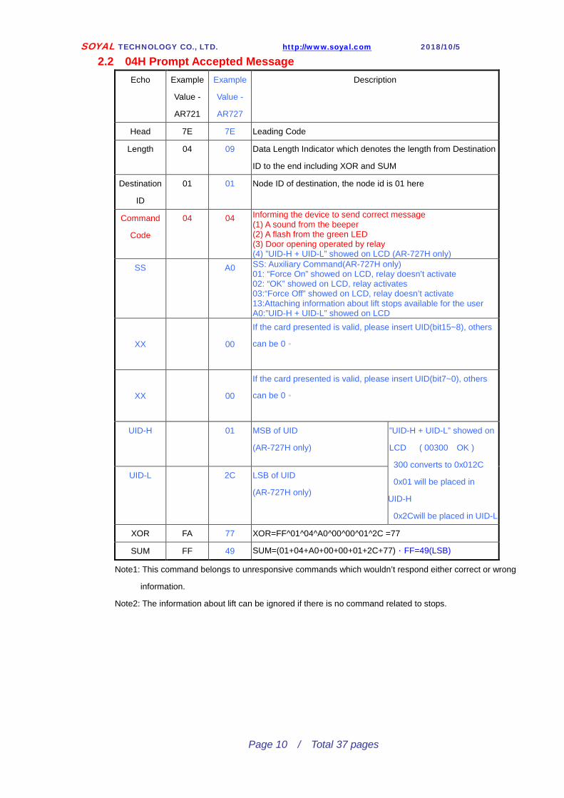
2.2 04H Prompt Accepted Message Echo Example
Value -
AR721
Example
Value -
AR727
Description
Head 7E 7E Leading Code
Length 04 09 Data Length Indicator which denotes the length from Destination
ID to the end including XOR and SUM
Destination
ID
01 01 Node ID of destination, the node id is 01 here
Command
Code
04 04 Informing the device to send correct message (1) A sound from the beeper (2) A flash from the green LED (3) Door opening operated by relay (4) ”UID-H + UID-L” showed on LCD (AR-727H only)
SS A0 SS: Auxiliary Command(AR-727H only) 01: “Force On” showed on LCD, relay doesn’t activate 02: “OK” showed on LCD, relay activates 03:“Force Off” showed on LCD, relay doesn’t activate 13:Attaching information about lift stops available for the user A0:”UID-H + UID-L” showed on LCD
XX 00
If the card presented is valid, please insert UID(bit15~8), others
can be 0。
XX 00
If the card presented is valid, please insert UID(bit7~0), others
can be 0。
UID-H 01 MSB of UID
(AR-727H only)
”UID-H + UID-L” showed on
LCD ( 00300 OK )
300 converts to 0x012C
0x01 will be placed in
UID-H
0x2Cwill be placed in UID-L
UID-L 2C LSB of UID
(AR-727H only)
XOR FA 77 XOR=FF^01^04^A0^00^00^01^2C =77
SUM FF 49 SUM=(01+04+A0+00+00+01+2C+77).FF=49(LSB)
Note1: This command belongs to unresponsive commands which wouldn’t respond either correct or wrong
information.
Note2: The information about lift can be ignored if there is no command related to stops.

SOYAL TECHNOLOGY CO., LTD. http://www.soyal.com 2018/10/5
Page 11 / Total 37 pages
2.3 05H Prompt Invalid Message
Echo Example
Value
Description
Head 7E Leading Code
Length 04 Data Length Indicator which denotes the length from Destination ID to the
end including XOR and SUM
Destination
ID
01 Node ID of destination, the node id is 01 here
Command
Code
05 Informing the device to send wrong message (1) Two sounds from the beeper (2) Two flashes from the red LED
XOR FB XOR=FF^01^05 =FB
SUM 01 SUM=(01+05+FB).FF=01(LSB)
Note: This command belongs to unresponsive commands which wouldn’t respond either correct or wrong
information.

SOYAL TECHNOLOGY CO., LTD. http://www.soyal.com 2018/10/5
Page 12 / Total 37 pages
2.4 09H Prompt Keying-in Password
Echo Example
Value
Description
Head 7E Leading Code
Length 09 Data Length Indicator which denotes the length from Destination ID to the
end including XOR and SUM
Destination
ID
01 Node ID of destination, the node id is 01 here
Command
Code
09 Informing the device to send message about keying in password (1) Four sounds from the beeper Behind the command code, Data 0 should be 0x40, Data 1&2 are
undefined and Data 3&4 are the number sent from the device. The number
will be converted to a value with 5 digits (decimal) and showed on LCD
(AR-727H only).
Data 0 40 0x40(fixed)
Data 1 00 Undefined, value=00 is fixed
Data 2 00 Undefined, value=00 is fixed
Data 3 00 Num H MSB ”Num H Num L” showed on LCD (00088 OK )
Data 4 58 Num L LSB
XOR EF XOR=FF^01^09^40^00^00^00^58 =EF
SUM 91 SUM=(01+09+40+00+00+00+58+EF).FF=91(LSB)
Note: This command belongs to unresponsive commands which wouldn’t respond either correct or wrong
information.

SOYAL TECHNOLOGY CO., LTD. http://www.soyal.com 2018/10/5
Page 13 / Total 37 pages
2.5 20H Write EEPROM
Echo Example
Value
Description
Head 7E Leading Code
Length 0F Data Length Indicator which denotes the length from Destination ID to the
end including XOR and SUM
Destination
ID
01 Node ID of destination, the node id is 01 here
Command
Code
20 Write EEPROM can up to 8bytes at a time (721HV3/727HV3 can be up to 32 bytes at a time)
Please refer to section 3.5 for more details
AddrH 00 Writing address in EEPROM
AddrL 80
Bytes 08 8 bytes
Data 0 11 Byte 1
Data 1 22 Byte 2
Data 2 33 Byte 3
Data 3 44 Byte 4
Data 4 55 Byte 5
Data 5 66 Byte 6
Data 6 77 Byte 7
Data 7 88 Byte 8
XOR DE XOR= FF^01^20^00^80^08^11^22^33^44^55^66^77^88 =DE
SUM EB SUM=(01+20+00+80+08+11+22+33+44+55+66+77+88+DE).
FF=EB(LSB)
Echo Value Description
Head 7E Leading Code
Length 05 Data Length Indicator which denotes the length from Node to the end
including XOR and SUM
Node 00 The value 00 is fixed, the message would be sent to PC from the device
Function
Cod
04 Command Acknowledged ( ACK )
Reader ID 01 Reader ID
XOR FA XOR=FF^00^04^01 =FA
SUM FF SUM=00+04+01+FA=FF

SOYAL TECHNOLOGY CO., LTD. http://www.soyal.com 2018/10/5
Page 14 / Total 37 pages
2.6 12H Read EEPROM
Echo Example
Value
Description
Head 7E Leading Code
Length 07 Data Length Indicator which denotes the length from Destination ID to the
end including XOR and SUM
Destination
ID
01 Node ID of destination, the node id is 01 here
Command
Code
12 Read EEPROM up to 8bytes at a time (721HV3/727HV3 can be up to 32 bytes at a time)
Please refer to section 3.5 for more details
AddrH 00 Reading address out from EEPROM
AddrL 80
Bytes 08 8bytes
XOR 64 XOR=FF^01^12^00^80^08 =64
SUM FF SUM=01+12+00+80+08+64=FF
Echo Value Description
Head 7E Leading Code
Length 0D Data Length Indicator which denotes the length from Node to the end
including XOR and SUM
Node 00 The value 00 is fixed, the message would be sent to PC from the device
Function 02 Message sent from the device
Reader ID 01 Reader ID
Data Field 11 Data 0
22 Data 1
33 Data 2
44 Data 3
55 Data 4
66 Data 5
77 Data 6
88 Data 7
XOR 74 XOR=FF^00^02^01^11^22^33^44^55^66^77^88 =74
SUM DB SUM=(00+02+01+11+22+33+44+55+66+77+88+74).FF=DB(LSB)
SOYAL TECHNOLOGY CO., LTD. http://www.soyal.com 2018/10/5
Page 15 / Total 37 pages
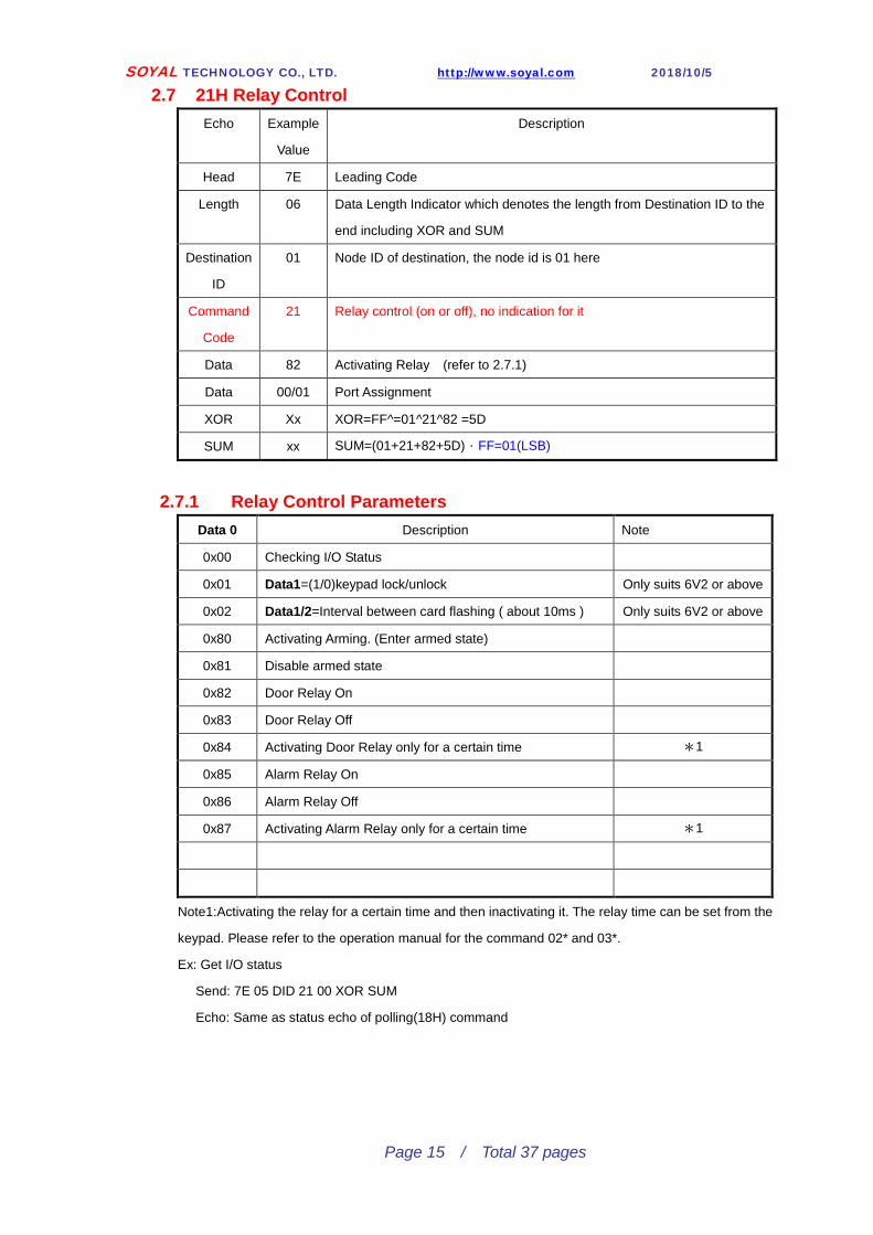
2.7 21H Relay Control Echo Example
Value
Description
Head 7E Leading Code
Length 06 Data Length Indicator which denotes the length from Destination ID to the
end including XOR and SUM
Destination
ID
01 Node ID of destination, the node id is 01 here
Command
Code
21 Relay control (on or off), no indication for it
Data 82 Activating Relay (refer to 2.7.1)
Data 00/01 Port Assignment
XOR Xx XOR=FF^=01^21^82 =5D
SUM xx SUM=(01+21+82+5D).FF=01(LSB)
2.7.1 Relay Control Parameters Data 0 Description Note
0x00 Checking I/O Status
0x01 Data1=(1/0)keypad lock/unlock Only suits 6V2 or above
0x02 Data1/2=Interval between card flashing ( about 10ms ) Only suits 6V2 or above
0x80 Activating Arming. (Enter armed state)
0x81 Disable armed state
0x82 Door Relay On
0x83 Door Relay Off
0x84 Activating Door Relay only for a certain time *1
0x85 Alarm Relay On
0x86 Alarm Relay Off
0x87 Activating Alarm Relay only for a certain time *1
Note1:Activating the relay for a certain time and then inactivating it. The relay time can be set from the
keypad. Please refer to the operation manual for the command 02* and 03*.
Ex: Get I/O status
Send: 7E 05 DID 21 00 XOR SUM
Echo: Same as status echo of polling(18H) command

SOYAL TECHNOLOGY CO., LTD. http://www.soyal.com 2018/10/5
Page 16 / Total 37 pages
2.8 23H Write Device Real Time Clock Echo Example
Value
Description
Head 7E Leading Code
Length 0B Data Length Indicator which denotes the length from Destination ID to the
end including XOR and SUM
Destination
ID
01 Node ID of destination, the node id is 01 here
Command
Code
23 Writing in the device time
SEC 00 Second
MIN 01 Minute
HR 02 Hour
WEEK 03 Day of a week
DAY 04 Date
MON 05 Month
YEAR 06 Year
XOR DA XOR=FF^01^23^00^01^02^03^04^05^06 =DA
SUM 13 SUM=(01+23+00+01+02+03+04+05+06+DA).FF=13(LSB)
Echo Value Description
Head 7E Leading Code
Length 05 Data Length Indicator which denotes the length from Node to the end
including XOR and SUM
Node 00 The value 00 is fixed, the message would be sent to PC from the device
Function 04 Command Acknowledged ( ACK )
Reader ID 01 Reader ID
XOR FA XOR=FF^00^04^01 =FA
SUM FF SUM=00+04+01+FA=FF

SOYAL TECHNOLOGY CO., LTD. http://www.soyal.com 2018/10/5
Page 17 / Total 37 pages
2.9 24H Read Device Real Time Clock Echo Example
Value Description
Head 7E Leading Code
Length 04 Data Length Indicator which denotes the length from Destination ID to the
end including XOR and SUM
Destination
ID
01 Node ID of destination, the node id is 01 here
Command
Code
24 Reading out the device time
XOR DA XOR=FF^01^24 =DA
SUM FF SUM=01+24+DA=FF
Echo Value Description
Head 7E Leading Code
Length 11 Data Length Indicator which denotes the length from Node to the end
including XOR and SUM
Node 00 The value 00 is fixed, the message would be sent to PC from the device
Function 03 Response to the request
Reader ID 01 Reader ID
Data Field 0A Data 0 Second
16 Data 1 Minute
0D Data 2 Hour
06 Data 3 Day of a week
09 Data 4 Date
0C Data 5 Month
05 Data 6 Year
63 Data 7 Firmware Version 6V3
27 Data 8 Door Number High byte (Used for 701Client huge door mode)
01 Data 9 Door Number Low Byte
01 Data 10 Firmware Identify Code (Ver6.6 and later)
00: Is standard firmware
26 Data 11 Reader Type
XOR AE XOR=FF^00^03^01^0A^16^0D^06^09^0C^05^63^27 =AE
SUM 89 SUM=(00+03+01+0A+16+0D+06+09+0C+05+63+27+AE).FF=89(LSB)

SOYAL TECHNOLOGY CO., LTD. http://www.soyal.com 2018/10/5
Page 18 / Total 37 pages
2.11 25H Get the lasted event Log of Device
Echo Example
Value
Description
Head 7E Leading Code
Length 04 Data Length Indicates which denotes the length from Destination ID to the
end including XOR and SUM
Destination
ID
01 Node ID of destination, the node id is 01 here
Command
Code
25 Reading events from the device
XOR DB XOR=FF^01^25 =DB
SUM 01 SUM=(01+25+DB).FF=01(LSB)
If there have no any events will echo command 0x04 and the package length will less then 0x0B, otherwise will
echo message package in message format.
SOYAL TECHNOLOGY CO., LTD. http://www.soyal.com 2018/10/5
Page 19 / Total 37 pages
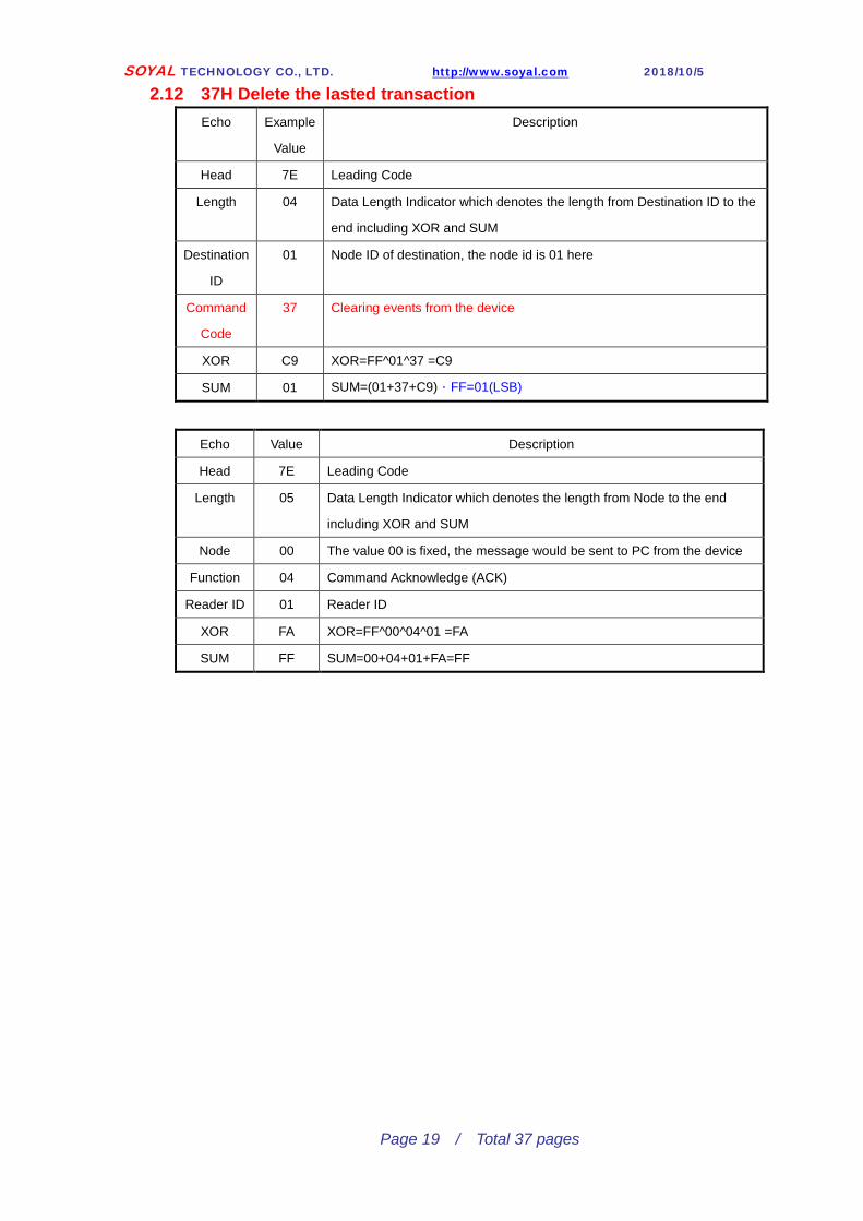
2.12 37H Delete the lasted transaction
Echo Example
Value
Description
Head 7E Leading Code
Length 04 Data Length Indicator which denotes the length from Destination ID to the
end including XOR and SUM
Destination
ID
01 Node ID of destination, the node id is 01 here
Command
Code
37 Clearing events from the device
XOR C9 XOR=FF^01^37 =C9
SUM 01 SUM=(01+37+C9).FF=01(LSB)
Echo Value Description
Head 7E Leading Code
Length 05 Data Length Indicator which denotes the length from Node to the end
including XOR and SUM
Node 00 The value 00 is fixed, the message would be sent to PC from the device
Function 04 Command Acknowledge (ACK)
Reader ID 01 Reader ID
XOR FA XOR=FF^00^04^01 =FA
SUM FF SUM=00+04+01+FA=FF
SOYAL TECHNOLOGY CO., LTD. http://www.soyal.com 2018/10/5
Page 20 / Total 37 pages
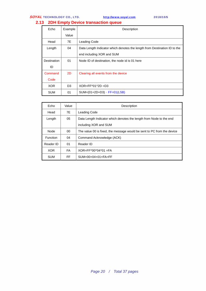
2.13 2DH Empty Device transaction queue
Echo Example
Value
Description
Head 7E Leading Code
Length 04 Data Length Indicator which denotes the length from Destination ID to the
end including XOR and SUM
Destination
ID
01 Node ID of destination, the node id is 01 here
Command
Code
2D Clearing all events from the device
XOR D3 XOR=FF^01^2D =D3
SUM 01 SUM=(01+2D+D3).FF=01(LSB)
Echo Value Description
Head 7E Leading Code
Length 05 Data Length Indicator which denotes the length from Node to the end
including XOR and SUM
Node 00 The value 00 is fixed, the message would be sent to PC from the device
Function 04 Command Acknowledge (ACK)
Reader ID 01 Reader ID
XOR FA XOR=FF^00^04^01 =FA
SUM FF SUM=00+04+01+FA=FF

SOYAL TECHNOLOGY CO., LTD. http://www.soyal.com 2018/10/5
Page 21 / Total 37 pages
2.17 81H Resetting Device
Echo Example
Value
Description
Head 7E Leading Code
Length 07 Data Length Indicator which denotes the length from Destination ID to the
end including XOR and SUM
Destination
ID
01 Node ID of destination, the node id is 01 here
Command
Code
81 Resetting the device (AR-727H only)
Dat0 46 ASCII ‘F’
Dat1 41 ASCII ‘A’
Dat2 43 ASCII ‘C’
XOR
SUM
*) This command will reset the controller and without any return data

SOYAL TECHNOLOGY CO., LTD. http://www.soyal.com 2018/10/5
Page 22 / Total 37 pages
2.19 83H Setting Card Content
Echo Value Description
Head 7E Leading Code
Length 0E Data Length Indicator which denotes the length from Destination ID to the
end including XOR and SUM
Destination
ID
01 Node ID of destination, the node id is 01 here
Command
Code
83 Setting card content (AR-721H / AR-727HV3 only)
Addr H 00 User Address – High Addr H Addr L=0x01(00001)
User Address : 00001 Addr L 01 User Address - Low
Site H 04 Site Code – High Site Hi Site Lo = 0x441 (01089)
Site Code 01089 Site L 41 Site Code – Low
Card H EA Card Code – High Card Hi Card Lo = 0xEA4B (59979)
Card Code 59979 Card L 4B Card Code – Low
PIN H 04 PIN – High PIN H PIN L=0x4D2(1234)
PIN 1234 PIN L D2 PIN – Low
Mode 02 Card or PIN Access Mode( Bit 1~0)
0 Invalid
1 Read Only
2 Card or PIN
3 Card + PIN
Bit7: Set to enable Anti passback
Zone 01 Selecting the 1st Time Zone (63 Time Zones for selection)
Group Bit mapping of Door Group. (B0:WG1, B1:WG2, B3:WG3, B4:WG4)
※ for AR721E only.
XOR xx XOR=FF^01^83^00^01^04^41^EA^4B^04^D2^02^01 =4D
SUM xx SUM=(01+83+00+01+04+41+EA+4B+04+D2+02+01+4D).FF=25(LSB)
Echo Value Description
Head 7E Leading Code
Length 05 Data Length Indicator which denotes the length from Node to the end
including XOR and SUM
Node 00 The value 00 is fixed, the message would be sent to PC from the device
Function 04 Command Acknowledge (ACK)
Reader ID 01 Reader ID
XOR FA XOR=FF^00^04^01 =FA
SUM FF SUM=00+04+01+FA=FF

SOYAL TECHNOLOGY CO., LTD. http://www.soyal.com 2018/10/5
Page 23 / Total 37 pages
2.20 87H Reading Card Content Echo Example
Value
Description
Head 7E Leading Code
Length 07 Data Length Indicator which denotes the length from Destination ID to the
end including XOR and SUM
Destination
ID
01 Node ID of destination, the node id is 01 here
Command
Code
87 Reading the card content
Addr H 00 User Address – High Addr H Addr L=0x02(00002)
User Address : 00002 Addr L 02 User Address - Low
Nums 01 Number of cards
XOR 7A XOR=FF^01^87^00^02^01 =7A
SUM 05 SUM=(01+87+00+02+01+7A).FF=05(LSB)
Echo Value Description
Head 7E Leading Code
Length 0D Data Length Indicator which denotes the length from Node to the end
including XOR and SUM
Node 00 The value 00 is fixed, the message would be sent to PC from the device
Function 03 Response to the request
Reader ID 01 Reader ID
Data Field 04 Data 0 Site Code – High Site Hi Site Lo = 0x441 (01089)
Site Code : 01089 41 Data 1 Site Code – Low
EA Data 2 Card Code – High Card Hi Card Lo = 0xEA4B (59979)
Card Code : 59979 4B Data 3 Card Code – Low
04 Data 4 PIN – High PIN H PIN L=0x4D2(1234)
PIN : 1234 D2 Data 5 PIN - Low
02 Data 6 Access Mode Card or PIN
0B Data 7 Time Zone 11st Time Zone Selected
03 Data8 Door Group
Data8 High Tag ID (bit41~38) For Sony Tag Only
Data9 High Tag ID (bit37~32) For Sony Tag Only
XOR C6 XOR=FF^00^03^01^04^41^EA^4B^04^D2^02^0B =C6
SUM 27 SUM=(00+03+01+04+41+EA+4B+04+D2+02+0B+C6).FF=27(LSB)

SOYAL TECHNOLOGY CO., LTD. http://www.soyal.com 2018/10/5
Page 24 / Total 37 pages
2.21 84H Stopping Waiting for Response
Echo Example
Value
Description
Head 7E Leading Code
Length 04 Data Length Indicator which denotes the length from Destination ID to the
end including XOR and SUM
Destination
ID
01 Node ID of destination, the node id is 01 here
Command
Code
84 Stopping waiting for response. When the controller receives events from
the device (reader), the device will wait for the response- ACK or NACK
from the controller, otherwise the device will show error message in 2.5
sec.
Note: This command is unresponsive command which wouldn’t respond
either correct or wrong information.
XOR 7A XOR=FF^01^84 =7A
SUM FF SUM=01+84+7A=FF
Echo Value Description
Head 7E Leading Code
Length 05 Data Length Indicator which denotes the length from Node to the end
including XOR and SUM
Node 00 The value 00 is fixed, the message would be sent to PC from the device
Function 04 Command Acknowledged ( ACK )
Reader ID 01 Reader ID
XOR FA XOR=FF^00^04^01 =FA
SUM FF SUM=00+04+01+FA=FF

SOYAL TECHNOLOGY CO., LTD. http://www.soyal.com 2018/10/5
Page 25 / Total 37 pages
2.22 85H Clearing All Card Content Echo Example
Value
Description
Head 7E Leading Code
Length 04 Data Length Indicator which denotes the length from Destination ID to the
end including XOR and SUM
Destination
ID
01 Node ID of destination, the node id is 01 here
Command
Code
85 Clearing all card content, this requests 10 sec. to process (AR-721H /
727HV1 / 721QFM Only)
XOR 7B XOR=FF^01^85 =7B
Option 0x01 Set Bit0 to clear all normal tag ID
Set Bit1 to clear all black tag ID
*) Only 721Q(Ver6.6 and later)/323D(Ver6.8 and later) supported
SUM 01 SUM=(01+85+7B).FF=01(LSB)
Echo Value Description
Head 7E Leading Code
Length 05 Data Length Indicator which denotes the length from Node to the end
including XOR and SUM
Node 00 The value 00 is fixed, the message would be sent to PC from the device
Function 04 Command Acknowledged ( ACK )
Reader ID 01 Reader ID
XOR FA XOR=FF^00^04^01 =FA
SUM FF SUM=00+04+01+FA=FF

SOYAL TECHNOLOGY CO., LTD. http://www.soyal.com 2018/10/5
Page 26 / Total 37 pages
2.23 86H Resetting Anti-pass-back Echo Example
Value
Description
Head 7E Leading Code
Length 04 Data Length Indicator which denotes the length from Destination ID to the
end including XOR and SUM
Destination
ID
01 Node ID of destination, the node id is 01 here
Command
Code
86 Restoring the initial setup of anti-pass-back (AR-721H / 727HV3 only)
XOR 78 XOR=FF^01^86 =78
SUM FF SUM=01+86+78=FF
Echo Value Description
Head 7E Leading Code
Length 05 Data Length Indicator which denotes the length from Node to the end
including XOR and SUM
Node 00 The value 00 is fixed, the message would be sent to PC from the device
Function 04 Command Acknowledged ( ACK )
Reader ID 01 Reader ID
XOR FA XOR=FF^00^04^01 =FA
SUM FF SUM=00+04+01+FA=FF

SOYAL TECHNOLOGY CO., LTD. http://www.soyal.com 2018/10/5
Page 27 / Total 37 pages
2.24 2AH Setting Time Zone Echo Exampl
e Value
Description
Head 7E Leading Code
Length 24 Data Length Indicator which denotes the length from Destination ID to the
end including XOR and SUM
Destinatio
n ID
01 Node ID of destination, the node id is 01 here
Command
Code
2A Setting Time Zone
IDX 01 Initial time zone, the
initial time zone is the
1st here
There are 63 time zones for selection
(01h~3Fh)
Value=00h : Auto-shift setup (please refer to
2.24.1)
Sets 01 Number of time zone to setup
Data 0 40 Ends data here The time zone to connect next set of time zone
Bit7 : Allows exiting on holidays
Bit6 ~Bit0 : The time zone to connect next set
of time zone
Data 1 00 Priority of time zone, users are only allowed to pass when their card level >
time zone level
Data 2 01 Sun. Beginning
Time ( 08:00 )
0x1E0
32bytes within the data, the first two bytes are
Link and Level
Data 0 : Link
Data 1 : Level
Data 2 Data 3 : Beginning time on Sunday
08:00 refers to 8 a.m.,
Namely 480 minutes (0x1E0)
Data 4 Data 5 : End time on Sunday
Data 6 Data 9 : Monday
Data 10 Data 13 : Tuesday
Data 14 Data 17 : Wednesday
Data 18 Data 21 : Thursdays
Data 22 Data 25 : Friday
Data 26 Data 29 : Saturday
Data 30 : Reserved
Data 31 : Reserved
Data 3 E0
Data 4 03 End Time
( 18:00 )
0x384
Data 5 84
Data 6 01 Mon. Beginning
Time ( 08:00 )
0x1E0
Data 7 E0
Data 8 03 End Time
( 18:00 )
0x384
Data 9 84
Data 10 01 Tue. Beginning
Time ( 08:00 )
0x1E0
Data 11 E0
Data 12 03 End Time
( 18:00 )
0x384
Data 13 84

SOYAL TECHNOLOGY CO., LTD. http://www.soyal.com 2018/10/5
Page 28 / Total 37 pages
Data 14 01 Wed. Beginning
Time ( 08:00 )
0x1E0
Data 15 E0
Data 16 03 End Time
( 18:00 )
0x384
Data 17 84
Data 18 01 Thu. Beginning
Time ( 08:00 )
0x1E0
Data 19 E0
Data 20 03 End Time
( 18:00 )
0x384
Data 21 84
Data 22 01 Fri. Beginning
Time ( 08:00 )
0x1E0
Data 23 E0
Data 24 03 End Time
( 18:00 )
0x384
Data 25 84
Data 26 01 Sat. Beginning
Time ( 08:00 )
0x1E0
Data 27 E0
Data 28 03 End Time
( 18:00 )
0x384
Data 29 84
XOR BE XOR=FF^01^2A^01^01^0C^00^01^E0^03^84^01^E0^03^84^01^E0^03
^84^01^E0^03^84^01^E0^03^84^01^E0^03^84^01^E0^03^84^00
^00 =BE
SUM CF SUM=(01+2A+01+01+0C+00+01+E0+03+84+01+E0+03+84+01+E0+03+
84+01+E0+03+84+01+E0+03+84+01+E0+03+84+01+E0+03+84
+00+00+BE).FF=CF(LSB)

SOYAL TECHNOLOGY CO., LTD. http://www.soyal.com 2018/10/5
Page 29 / Total 37 pages
2.24.1 Auto-shift Setup When the value of time zone is 00, it refers to auto-shift
Beginning
Time
End Time Description
00:00 00:00 Always On Duty
23:59 23:59 Always Off Duty
00:01 00:01 Duty status depends on the last setting and will be fixed on it
Example
08:00 18:00 ( Overtime Setup )
Before 08:00 On Duty,Before 18:00 Off Duty,After 18:00 Off OVT
08:00 23:59 ( Non-overtime Setup )
Before 08:00 On duty,Before 23:59 Off Duty
Echo Value Description
Head 7E Leading Code
Length 05 Data Length Indicator which denotes the length from Node to the end
including XOR and SUM
Node 00 The value 00 is fixed, the message would be sent to PC from the device
Function 04 Command Acknowledged ( ACK )
Reader ID 01 Reader ID
XOR FA XOR=FF^00^04^01 =FA
SUM FF SUM=00+04+01+FA=FF

SOYAL TECHNOLOGY CO., LTD. http://www.soyal.com 2018/10/5
Page 30 / Total 37 pages
2.25 2CH Setting Holidays
Echo Example
Value
Description
Head 7E Leading Code
Length 12 Data Length Indicator which denotes the length from Destination ID to the
end including XOR and SUM
Destination 01 Node ID of destination, the node id is 01 here
Code 2C Setting Holidays (AR-721H / 727HV3 only)
IDX 00 First set of holidays 120 days available to setup for holiday, sorting
before download and put the small date first
then follow zero to fill all filed.
Sets 06 Number of holidays, 06
refers to 6-day holiday
Data 0 0C December Set 00
Dec. 1 Data 1 01 1
Data 2 0C December Set 01
Dec. 2 Data 3 02 2
Data 4 0C December Set 02
Dec. 3 Data 5 03 3
Data 6 0C December Set 03
Dec. 4 Data 7 04 4
Data 8 0C December Set 04
Dec. 5 Data 9 05 5
Data 10 0C December Set 05
Dec. 6 Data 11 06 6
XOR D3 XOR=FF^01^2C^00^06^0C^01^0C^02^0C^03^0C^04^0C^05^0C^06 =D3
SUM 63 SUM=(01+2C+00+06+0C+01+0C+02+0C+03+0C+04+0C+05+0C+06
+D3).FF=63(LSB)
Echo Value Description
Head 7E Leading Code
Length 05 Data Length Indicator which denotes the length from Node to the end
including XOR and SUM
Node 00 The value 00 is fixed, the message would be sent to PC from the device
Function 04 Command Acknowledged ( ACK )
Reader ID 01 Reader ID
XOR FA XOR=FF^00^04^01 =FA
SUM FF SUM=00+04+01+FA=FF

SOYAL TECHNOLOGY CO., LTD. http://www.soyal.com 2018/10/5
Page 31 / Total 37 pages
2.26 88H Set Extend Parameter 2.26.1 Read
Echo Example
Value
Description
Head 7E Leading Code
Length 12 Data Length Indicator which denotes the length from Destination ID to the
end including XOR and SUM
Destination 01 Node ID of destination, the node id is 01 here
Code 88 Set extend parameters of user access date
Sub Code 00 00 : Read, 01: Write
Data 00 User Index High (bit 15~08)
01 User Index Low (bit 07~00)
00 How many records high byte (bit 15~08)
01 How many records low byte (bit 07~00)
XOR
SUM
Echo Value Description
Head 7E Leading Code
Length 05 Data Length Indicator which denotes the length from Node to the end
including XOR and SUM
Node 00 The value 00 is fixed, the message would be sent to PC from the device
Data First record of begin year. (Each record take 8 bytes)
Month of begin
Day of begin
Year of end
Month od end
Day of end
0xFF
0xFF
Second record of begin year
…
XOR FA XOR=FF^00^04^01 =FA
SUM FF SUM=00+04+01+FA=FF

SOYAL TECHNOLOGY CO., LTD. http://www.soyal.com 2018/10/5
Page 32 / Total 37 pages
2.26.2 Write Echo Example
Value
Description
Head 7E Leading Code
Length 12 Data Length Indicator which denotes the length from Destination ID to the
end including XOR and SUM
Destination 01 Node ID of destination, the node id is 01 here
Code 88 Set extend parameters of user access date
Sub Code 01 00 : Read, 01: Write
Data User Index High (bit 15~08)
User Index Low (bit 07~00)
How many records high byte (bit 15~08)
How many records low byte (bit 07~00)
First record begin year
Begin month
Begin day
End year
End month
End day
0xFF (Must be 0xFF)
0xFF (Must be 0xFF)
Second record begin year
…
XOR
SUM
Echo Value Description
Head 7E Leading Code
Length 05 Data Length Indicator which denotes the length from Node to the end
including XOR and SUM
Node 00 The value 00 is fixed, the message would be sent to PC from the device
Function 04 Command Acknowledged ( ACK )
Reader ID 01 Reader ID
XOR FA XOR=FF^00^04^01 =FA
SUM FF SUM=00+04+01+FA=FF

SOYAL TECHNOLOGY CO., LTD. http://www.soyal.com 2018/10/5
Page 33 / Total 37 pages
3 Data Structure 3.2Structure of Time Zone : Struct DS_ZONE {
Unsigned char link; //Bit 7 refers to free pass on holidays
Unsigned char level; //While card level<ZONE level→ Pass Denied
Unsigned int16 Time[7][2] //Minute as a unit to set
Unsigned char rev[2]
};
Data 0 : Link
Data 1 : Level
Beginning Time End Time
High Low High Low
Sunday Data 2 Data 3 Data 4 Data 5
Monday Data 6 Data 7 Data 8 Data 9
Tuesday Data 10 Data 11 Data 12 Data 13
Wednesday Data 14 Data 15 Data 16 Data 17
Thursday Data 18 Data 19 Data 20 Data 21
Friday Data 22 Data 23 Data 24 Data 25
Saturday Data 26 Data 27 Data 28 Data 29
Data 30 : Reserved
Data 31 : Reserved
63 time zones available to setup, Time Zone 0 refers to Auto-shift
3.3 Data Structure of Holidays : Struct DS_HOLI {
Unsigned char month;
Unsigned char data;
};
Set 00 Set 01
・・・・・・・
Set xx
Month Date Month Date Month Date
Data 0 Data
1
Data 2 Data 3 Data xx Data xx
120 days available to setup for holiday

SOYAL TECHNOLOGY CO., LTD. http://www.soyal.com 2018/10/5
Page 34 / Total 37 pages
3.4 Data Structure of Anti-pass-back: //Bit mapping to each user. Bit0 of byte0 is user 0 , bit7 of byte1 is user 15,etc.
//If set Enable[0] to 0xFF , the user from 0~7 need anti-pass-back check.
//If set Initial[0] to 0xFF , the user from 0~7 can access reader in free anti-pass-back
// state one times.
Struct DS_ANTIPASS {
Unsigned char Enable[1024 /8]; //Start from EEPROM address 8448(Dec)
Unsigned char Initial[1024 /8]; // Start from EEPROM address 8576(Dec)
};
Enable
1024 bits (1024 users)
Byte1 (8 users) Byte2 Byte3
………….. Byte128 User Address 7~0 User Address 15~
8
User Address 31~
16
0 0 0 0 0 0 0 1 0 0 0 0 0 0 1 1 0 1 0 1 1 1 0 0
1:Enable Anti-pass-back
0:Disable Anti-pass-back
Initial
1024 bits (1024 users)
Byte1 (8 users) Byte1 (8 users) Byte1 (8 users)
………….. Byte128 User Address 7~0 User Address 7~0 User Address 7~0
0 0 0 0 0 0 0 1 0 0 0 0 0 0 1 1 0 1 0 1 1 1 0 0
1:Initial Enabling
0:Non-initial Eabling
Current state
1024 bits (1024 users)
Byte1 (8 users) Byte1 (8 users) Byte1 (8 users)
………….. Byte128 User Address 7~0 User Address 7~0 User Address 7~0
0 0 0 0 0 0 0 1 0 0 0 0 0 0 1 1 0 1 0 1 1 1 0 0
1:Entry Door
0:Exit Door

SOYAL TECHNOLOGY CO., LTD. http://www.soyal.com 2018/10/5
Page 35 / Total 37 pages
3.5 Memory Layout of AR-721E: The capacity of EEPROM of AR-721E can be up to 256Kbits. The first 30 bytes are system
parameters as tabled below
Address Description Function Bytes
00h System Flag Reserved 6
06h Port 0 Option 0 1
07h Port 0 Option 1 1
08h Door Number of Port 0 1
09h Reader Type Don’t change 1
0Ah Port 0 Option 3 1
0Bh Controller Operation Mode Must be 4, 6, or 8 1
0C~0Dh Mode 6 Access Password 2
0E~11h Master Password 4
12~13h Port 0 Door Relay Time Base on 10ms 2
14~15h Alarm Relay Time Base on 10ms 2
16h Port 0 Option 2 1
17h Port 0 Option 4 1
18~19h Port 1 Door Close Delay Time Base on 10ms 2
1A~1Bh Alarm Delay Time Base on 10ms 2
1C~1Dh Port 0 Door Close Delay Time Base on 10ms 2
1E~1Fh Arming Password 2
26 ~ 27h Start time of Open Zone Set 1 Base on Minute: 01:20 = 0050h
28 ~ 29h Stop time of Open Zone Set 1 “
2A ~ 2Bh Start time of Open Zone Set 2 “
2C ~ 2Dh Stop time of Open Zone Set 2 “
2Eh Weekly table bit of Open Zone1 Available on weekday table
Bit1 for Sun, bit7 for Sat
2Fh Weekly table bit of Open Zone2
…
36H Door Number of Port 1
37H Port 1 Option 0
38H Port 1 Option 1
39H Port 1 Option 2
3AH Port 1 Option 3
3BH Port 1 Option 4
3C~3DH Port 1 Door Relay Time

SOYAL TECHNOLOGY CO., LTD. http://www.soyal.com 2018/10/5
Page 36 / Total 37 pages
Address Function bytes
0000h~00FFh System Parameters 256
0100h~30FFh UID of User 0 to 3071 Each UID has 32bits 12288
3100h~48FFh PIN of User 0 to 5119 Each PIN has 16bits 6144
4900h~60FFh Access Mode and Zone 6144
6100h~627Fh Enable flag of Anti-pass-back 384
6280h~63FFh Initial flag of Anti-pass-back 384
6400h~657Fh Current State flag of Anti-pass-back 384
6580h~65FFh Reserved
6600h~6DFFh Time ZONE DB from 0 to 63 384
6E00h~6EF0h Holiday table 240
reserved 16
6F00h ~ 9EFFh Lift stop information
6F00h bit0: Floor0, bit7: Floor7
6F01h bit0: Floor8, bit7:Floor15
…
* For 3072 users mode only 12288
9F00h ~ F9FFh Message information (1568) 25088
FA00h ~ FBFFh Reserved
SOYAL TECHNOLOGY CO., LTD. http://www.soyal.com 2018/10/5
Page 37 / Total 37 pages
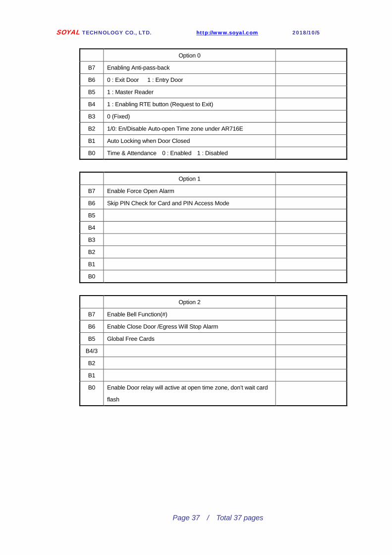
Option 0
B7 Enabling Anti-pass-back
B6 0 : Exit Door 1 : Entry Door
B5 1 : Master Reader
B4 1 : Enabling RTE button (Request to Exit)
B3 0 (Fixed)
B2 1/0: En/Disable Auto-open Time zone under AR716E
B1 Auto Locking when Door Closed
B0 Time & Attendance 0 : Enabled 1 : Disabled
Option 1
B7 Enable Force Open Alarm
B6 Skip PIN Check for Card and PIN Access Mode
B5
B4
B3
B2
B1
B0
Option 2
B7 Enable Bell Function(#)
B6 Enable Close Door /Egress Will Stop Alarm
B5 Global Free Cards
B4/3
B2
B1
B0 Enable Door relay will active at open time zone, don’t wait card
flash


![SOYAL AR-725-E · SOYAL ACCE C E ® AR-725-E V200114 a. d. e. ... [e.g.] User Address NO.101 to NO.120 have 20 pcs of sequential tags:(62312~62332): Access programming mode →](https://static.fdocuments.in/doc/165x107/5eaded9280337a69683871a6/soyal-ar-725-e-soyal-acce-c-e-ar-725-e-v200114-a-d-e-eg-user-address.jpg)