SOUTHEASTERN HIGH SPEED
73
SOUTHEASTERN HIGH SPEED EN
Transcript of SOUTHEASTERN HIGH SPEED

SOU
THEA
STER
N H
IGH
SPE
ED
EN

©2021 Dovetail Games, a trading name of RailSimulator.com Limited (“DTG”). "Dovetail Games", “Train Sim World” and “SimuGraph” are trademarks or registered trademarks of DTG. Unreal® Engine, ©1998-2021, Epic Games, Inc. All rights reserved. Unreal® is a registered trademark of Epic Games. Portions of this software utilise SpeedTree® technology (©2014 Interactive Data Visualization, Inc.). SpeedTree® is a registered trademark of Interactive Data Visualization, Inc. All rights reserved. Southeastern is the registered trade mark of The Go-Ahead Group PLC. Permission to use the Double Arrow Trade Mark is granted by the Secretary of State for Transport. All other copyrights or trademarks are the property of their respective owners and are used here with permission. Unauthorised copying, adaptation, rental, re-sale, arcade use, charging for use, broadcast, cable transmission, public performance, distribution or extraction of the product or any trademark or copyright work that forms part of this product is prohibited. Developed and published by DTG.

1 SOUTHEASTERN HIGH SPEED OVERVIEW
6 ROUTE MAP & POINTS OF INTEREST
2 THE BR CLASS 395 'JAVELIN'
THE BR CLASS 375 'ELECTROSTAR'3
4 USING THE INCLUDED TRAINS
7 GAME MODES
9 BR CLASS 395 DRIVING CAB: FRONT
11 BR CLASS 395 DRIVING CAB PANELS
5 INTRODUCING SOUTHEASTERN HIGH SPEED
8 INTRODUCING THE BR CLASS 395 'JAVELIN'
10 BR CLASS 395 DRIVING CAB: REAR
23 BR CLASS 395 DRIVING CAB: DRIVER'S SIDE
25 BR CLASS 395 DRIVING CAB PANELS
22 INTRODUCING THE BR CLASS 375 'ELECTROSTAR'
24 BR CLASS 395 DRIVING CAB: SECONDMAN'S SIDE
37 BR CLASS 395 ON-BOARD SYSTEMS: BRAKES
35 BR CLASS 395: GETTING STARTED
38 BR CLASS 395 ON-BOARD SYSTEMS: POWER SUPPLY
39 BR CLASS 375: GETTING STARTED
40 APPROACHING STATIONS & DOOR CONTROLS
41 EMERGENCY BRAKE RECOVERY
5 TRAIN SAFETY & IN-CAB SIGNALLING SYSTEMS
44 TRAIN PROTECTION & WARNING SYSTEM (TPWS)
45 KVB
43 AUTOMATIC WARNING SYSTEM (AWS)
47 TVM-430
6 BRITISH RAILWAY SIGNALLING
56 SEMAPHORE
57 REACTING TO MAIN ASPECT SIGNALS
50 COLOUR LIGHT
58 DISTANT OR RELATED SIGNALS
59 SIGNAL TYPES
62 BANNER REPEATERS & POSITION LIGHTS
7 RAILWAY SIGNS65 PERMITTED SPEED, WHISTLE & COASTING BOARDS
8 GENERAL INFORMATION69 DOVETAIL LIVE
70 TROUBLESHOOTING
71 CREDITS & ACKNOWLEDGEMENTS
66 CTRL/HS1 TRACKSIDE SIGNS
CONTENTS

SOUTHEASTERN HIGH SPEED OVERVIEW1

Experience the unique and exciting blend of classic main line running and thrilling high-speed commuting, aboard state-of-the-art motive power, in London and the Garden of England with Train Sim World 2: Southeastern High Speed. The Chatham Main Line dates back to the 1860s, and has since its inception provided a link between the Medway towns and London. Despite revolutionary upgrades throughout the decades such as quadrupling of certain sections, and the bold Kent Coast Electrification scheme, journey times to the capital were still in excess of one hour. However, the call for improvement was answered in 2009, when Southeastern commenced operating domestic high-speed services on the newly built High Speed 1 route. For the past decade, services have been racing from the nation’s capital to Ebbsfleet, from where they join the classic lines and serve Gravesend, Medway and beyond. It’s your job to take charge of these vital services; whisk commuters across the route, master the TVM430 signalling system on HS1, and keep an eye on more traditional signals on the classic lines. Awe at contrasting modern and historical infrastructure, and take-in the sights of a renewed Medway with rebuilt Strood and Rochester stations. Take control of the striking BR Class 395 ‘Javelin’ EMU, adorning 10th anniversary branding commemorating the first decade of operation, as well as the colourful #trainbow variant which celebrates Pride, on services between London and Faversham. Alternatively, get a taste of classic commuting from the cab of the popular BR Class 375/9 Electrostar EMU.
4INTRODUCING SOUTHEASTERN HIGH SPEED

Passenger StationsSidings / YardsNotable LandmarksRepresented RailwayRepresented Railway (Not Player Accessible)
N
Faversham
Faversham Carriage Sidings
TeynhamSittingbourne
NewingtonRainham
Gillingham
Gillingham Depot
Chatham
Rochester
Rochester Bridges/Castle & Cathedral
Strood
HighamHoo Junction
GravesendQE2 Bridge
Cement Works
Ebbsfleet International
Rainham (Essex)Dagenham Dock
Dagenham Sidings
Stratford International
St Pancras International
BT Tower
5 ROUTE MAP & POINTS OF INTEREST

THE BR CLASS 395'JAVELIN'2

JOURNEYS
Blends together more than 24 hours of sequential gameplay. Start a Journey and enjoy hundreds of scenarios, timetabled services, and jobs to complete around the railway.
TRAINING
Training modules give you the knowledge you need to get the most from your locomotives and trains via interactive lessons that teach you key concepts. If you’re new to Train Sim World, we recommend you start here to learn the fundamentals.
SCENARIOS
Scenarios are objective-based activities which provide unique experiences. Move coaches around, drive passenger and freight services and experience some of the operations that occur on the route.
TIMETABLES
These provide a host of activities throughout an entire 24-hour time period; Timetable Mode is a new way to play. There’s always something to do with a large variety of services to take control of or ride along with. Sit back and enjoy the action and capture amazing screenshots, hop on or off and ride along with the various services as they go about their duties or take control and carry out the duties yourself. Featuring many individual services, you’ll always find something going on.
7 GAME MODES

The British Rail Class 395 was introduced in 2009 with the opening of High Speed 1 (HS1), a new line that brought European trains to London for the first time by way of the Channel Tunnel. The domestic services operated by the Class 395 gave commuters from Kent a faster trip to London, cutting some trips in half by sharing lines with European services. Rapid service to Stratford International in support of the 2012 Olympic Games quickly earned the Class 395 its Javelin nickname.
The Javelin was built by Hitachi in Kasado, Japan. Southeastern ordered 29 six-car sets that have a top speed on HS1 tracks of 225 km/h (140 mph). The train was designed by Alexander Neumeister, the designer of the ICE 3 and high-speed trains in several other countries. The dual-mode train can take power from HS1's overhead 25 kV AC wires with a pantograph or from standard 750 V DC with its third-rail shoe. It is also compatible with British safety and signalling systems as well as HS1's Continental systems.
Built as a dedicated commuter train, the Class 395 carries 352 passengers as a single six-car set, but often operates as 12-car trains. The dark-blue livery was developed specifically for Javelin service leading up to the Olympics but has been applied to other Southeastern trains in the years since.
8INTRODUCING THE BR CLASS 395 'JAVELIN'

A
B
C
D
E
F
9 BR CLASS 395 DRIVING CAB: FRONT
Panels artificially brightened for clarity

G
H
10BR CLASS 395 DRIVING CAB: REAR 10

1
3
4
2
5
67
815
14
13
12
10
11
9
16 1718
20
21
22
23
24
19
A B
11 BR CLASS 395 DRIVING CAB: PANELS A & B
Panels artificially brightened for clarity

25
26
27
C
12BR CLASS 395 DRIVING CAB: PANEL C

28
29
30
33
31
32
34 35 36 37 38 40 41
39 42
43 44 45 46 47 48 49
51 52 53
54
55
56
57
58
50
D
13 BR CLASS 395 DRIVING CAB: PANEL D

59 61
6362
E
64F 65
60
14BR CLASS 395 DRIVING CAB: PANELS E & F

66
67
G
15 BR CLASS 395 DRIVING CAB: PANEL G

68 69 70
71
72
73
H
16BR CLASS 395 DRIVING CAB: PANEL H

1 Sets the state of the cab climate control circulation fan.
2 Overrides the state of the cab climate control system.
3 Sets the climate control mode.
4 Sets the target temperature of the climate control system.
5 Overrides the temperature setpoint (non-functional).
6 Sets the state of the desk illumination (brightness of indicator lamps).
7 Sets the state of the reading light.
8 Sets the state of the cab light.
9 Displays the status of the exterior lighting.
10 Sets the state of the exterior lighting.
11 Sets the state of the exterior hazard lighting.
12 Signals to the guard via a pulse code system.
13 Sets the state of the left-side passenger entry doors.
14 Unlocks the left-side passenger entry doors throughout the train. Typically both buttons are pressed together.
15 Displays the status of the left-side passenger entry door interlock. When the indicator is unlit, the doors are unlocked and throttle input is disabled. Conversely, when the indicator is lit, the doors are locked and throttle input is enabled.
17 Sets the state of the Auxilliary electrical systems to off.
18 Sets the state of the current collection system to DC Mode.
19 Raises the pantograph and lowers the third-rail shoes depending which current collection mode has been set.
20 Activates the Channel Tunnel Rail Link (CTRL) power system.
21 Lowers the pantograph and raises the third-rail shoes.
16 Sets the state of the Auxilliary electrical systems to on.
17 BR CLASS 395 DRIVING CAB: PANELS A & B

22 Indicates that train fault alerts have been acknowledged.
23 Indicates the status of the On-Train Monitoring Recording (OTMR) system.
24 Train Management System (TMS) interactive touch screen.
25 Reverser enables the cab desk and sets the direction of travel.
26 Master Key unlocks the reverser.
27 The Power Handle or Combination Throttle & Brake Lever applies appropriate throttle input and also brakes the train. Pushing the lever forward applies brake input and gradually increases the force applied to the wheels. Pulling the lever backward, applies throttle input and gradually increases the force applied to the wheels which propels the train in the direction set.
28 Indicates the status of the eletrical current supply to the train. The indicator is lit when either the pantograph or shoes are in contact with the live current supply.
29 Indicates the status of the Main Circuit Breaker (MCB) and Vacuum Circuit Breaker (VCB). When lit, the MCB and/or VCB has been tripped and will need to be reset.
30 Indicates the status of the safety systems. If any system is isolated, the indicator is lit.
31 Couples the train at this end to another train. Coupling is entirely automatic.
32 Couples the train at the rear of the train to another train. Coupling is entirely automatic.
33 KVB System Control Panel is covered in greater detail later in this guide. See Page 28 for more details.
34 Prepares the train for coupling by opening the coupling hatch and extending the Scharfenberg coupler.
35 Wiper Interval sets the sweep interval to the number of sweeps per minute denoted by the value set.
36 Demists the forward windscreen (non-functional).
37 Sets the wiper mode.
18BR CLASS 395 DRIVING CAB: PANELS B, C & D

38 Indicates Train Protection & Warning System (TPWS) Brake Demand. The indicator will flash when TPWS or AWS has initiated a brake demand that has yet to be acknowledge by the driver. The indicator will be lit (steady) if a brake demand has been acknowledged by the driver. The indicator will be unlit in its normal operating state.
39 Performs a self-test of the TPWS system. All TPWS indicators will flash during the test.
40 The AWS Sunflower provides a visual indication that an AWS warning has been acknowledged by the driver.
41 Indicates that a fault has been detected in TPWS or it has been isolated.
42 Overrides the TPWS for 20 seconds to enable passing a Train Stop System (TSS) loop on the track.
43 Driver Reminder Appliance (DRA) disables throttle input and is used to remind the driver that the train is unsafe.
44 Reduces the brightness of the speedometer display.
45 The speedometer provides a visual indication of the train's current speed in either km/h or mph.
46 TVM-430 Panel. TVM-430 is covered in greater detail later in this guide. See Page XX for more details.
47 Increases the brightness of the speedometer display.
48 Brake gauge displays the current pressure of the brake system. The white needle displays the current pressure in the brake cylinders and the yellow needle displays the current pressure in the main reservoir.
49 Displays the total brake force being applied to the train as a percentage.
50 Sander enables the automatic sanding equipment.
51 Increases the arming status of the TVM-430 system.
52 Decreases the arming status of the TVM-430 system.
53 Disarms the TVM-430 system.
54 Dims the brightness of the TVM-430 'egg box' display.
55 Emergency brake slam switch activates the emergency brake.
56 Uncouples the train at this end from another train.
19 BR CLASS 395 DRIVING CAB: PANEL D

57 Sounds the depot whistle.
58 AWS/TPWS Reset or Acknowledge button.
59 DSD Holdover temporarily disables the driver vigilance device whilst shunting or coupling.
60 Unlocks the right-side passenger entry doors throughout the train. Typically both buttons are pressed together..
61 Sets the state of the right-side passenger entry doors.
62 Displays the status of the right-side passenger entry door interlock. When the indicator is unlit, the doors are unlocked and throttle input is disabled. Conversely, when the indicator is lit, the doors are locked and throttle input is enabled.
63 Sounds the main horn. Push forward to sound the high tone and pull backward for the low tone.
64 GSMR Device (non-functional).
65 Emergency brake slam switch activates the emergency brake.
66 TVM-430 Isolation Switch. TVM-430 is covered in greater detail later in this guide. See Page XX for more details.
67 KVB Isolation Switch. KVB is covered in greater detail later in this guide. See Page XX for more details.
68 AWS Isolation Switch enables/disables the Automatic Warning System.
69 DSD Isolation Switch enables/disables the Driver Safety Device.
70 Vigilance Isolation Switch enables/disables the Driver Vigilance Device.
71 DRA Isolation Switch enables/disables the Driver Reminder Appliance.
72 TPWS Temporary Isolation Switch temporarily disables the Train Protection & Warning System.
73 Sets the state of the Pantograph Selection to normal or emergency.
20BR CLASS 395 DRIVING CAB: PANELS D, E, F, G & H

THE BR CLASS 375'ELECTROSTAR'3

The British Rail Class 375 is an electric multiple unit (EMU) train that is part of the Electrostar family, forming a large part of Southeastern’s fleet of commuter trains. The Class 375 was introduced in 2001 by Adtranz (now Bombardier) and there are currently 112 units still operating out of the 140 originally produced.
All 27 four-car units of the Class 375/9 variant have been refurbished with Southeastern’s dark blue livery and are among the trains that now service the portion of the Chatham Main Line depicted in Train Sim World 2.
The Class 375/9 seats 273 passengers and can be coupled into sets of twelve cars. It takes power from the 750 V DC third rail and can reach a maximum speed of 100 mph (160 km/h) thanks to the 2,012 horsepower (1,500 kW) produced by the motors distributed throughout the four cars.
22INTRODUCING THE BR CLASS 375 'ELECTROSTAR'

A
B
C
23 BR CLASS 375 DRIVING CAB: DRIVER'S SIDE

D
E
24BR CLASS 375 DRIVING CAB: SECONDMAN'S SIDE

1
5
4
2 3
6
107 8 9
11
A
25 BR CLASS 375 DRIVING CAB: PANEL A
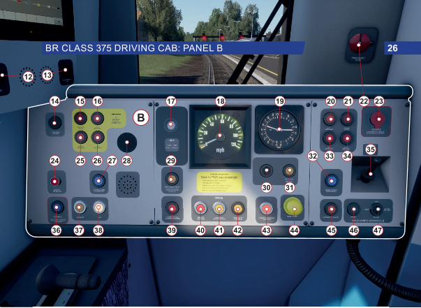
12 13
14 15 16 17 18 19 20 21 22 23
3525 26 28 292724
36 37 38 39 40 41 42 43
30 31
3332 34
44 45 46 47
B
26BR CLASS 375 DRIVING CAB: PANEL B

4849
50
5251C
27 BR CLASS 375 DRIVING CAB: PANEL C

53 54 55
56 57
58
D
28BR CLASS 375 DRIVING CAB: PANEL D
E
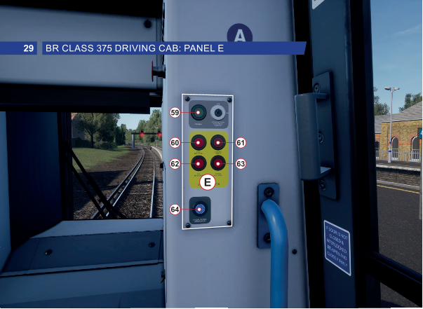
59
60
62
64
61
63
29 BR CLASS 375 DRIVING CAB: PANEL E

1 Displays the status of the exterior lighting.
2 Sets the state of the Auxilliary electrical systems to on.
3 Sets the state of the Auxilliary electrical systems to off.
4 Sets the state of the headlights.
5 Sets the state of the tail lights.
6 Sets the target temperature of the climate control system.
7 Sets the state of the DC Current Collection system.
8 Closes the Master Circuit Breaker and lowers the current collection shoes.
9 Opens the Master Circuit Breaker and raises the current collection shoes.
10 Sets the climate control mode.
11 Train Management System (TMS) interactive touch screen.
12 Signals to the guard via a pulse code system.
13 Sets the state of the notice board light.
14 Sets the state of the cab light on the right-hand side.
15 Indicates the status of the left-side passenger entry doors. When the indicator is lit, the left-side doors are open.
17 Driver Reminder Appliance (DRA) disables throttle input and is used to remind the driver that the train is unsafe.
18 Displays the current speed in mph.
19 Duplex brake gauge displays the air pressures of the master reservoir and brake cylinders.
20 Releases the right-side doors which have been pre-set for the station currently stopped at for Selective Door Opening (non-functional).
16 Releases the left-side doors which have been pre-set for the station currently stopped at for Selective Door Opening (non-functional).
21 Indicates the status of the right-side passenger entry doors. When the indicator is lit, the right-side doors are open.
30BR CLASS 375 DRIVING CAB: PANELS A & B

22 Emergency brake slam switch activates the emergency brake.
23 Uncouples the train at this end from another train.
24 Sounds the depot whistle.
25 Unlocks the left-side passenger entry doors throughout the train. Typically both 25 and 26 are pressed together.
26 Unlocks the left-side passenger entry doors throughout the train. Typically both 25 and 26 are pressed together.
27 Displays the status of the left-side passenger entry door interlock. When the indicator is unlit, the doors are unlocked and throttle input is disabled. Conversely, when the indicator is lit, the doors are locked and throttle input is enabled.
28 The AWS Sunflower provides a visual indication that an AWS warning has been acknowledged by the driver.
29 Traction Sand enables the automatic sanding equipment.
30 A remnant of the pre-refurbished cab speed set control (non-functional).
31 Sets the state of the anti-icing system (non-functional). Previously, this button would set the speed set system.
32 Indicates the status of the right-side passenger entry door interlock. When the indicator is unlit, the doors are unlocked and throttle input is disabled. Conversely, when the indicator is lit, the doors are locked and throttle input is enabled.
33 Unlocks the right-side passenger entry doors throughout the train. Typically both 33 and 34 are pressed together.
34 Unlocks the right-side passenger entry doors throughout the train. Typically both 33 and 34 are pressed together.
35 Sounds the main horn. Push forward to sound the high tone and pull backward for the low tone.
36 Couples the train at this end to another train.
37 Indicates the status of the Main Circuit Breaker (MCB) and Vacuum Circuit Breaker (VCB). When lit, the MCB and/or VCB has been tripped and will need to be reset.
38 Indicates the status of the eletrical current supply to the train. The indicator is lit when the shoes are in contact with the live current supply.
39 Indicates that train fault alerts have been acknowledged.
31 BR CLASS 375 DRIVING CAB: PANEL B

41 Indicates that a fault has been detected in TPWS or it has been isolated.
42 Overrides the TPWS for 20 seconds to enable passing a Train Stop System (TSS) loop on the track.
43 Indicates the status of the safety systems. If any system is isolated, the indicator is lit.
44 AWS/TPWS Reset or Acknowledge button.
45 Sets the state of the exterior hazard lighting.
46 Sets the state of the windscreen washer (non-functional).
47 Sets the state of the windscreen wipers.
48 The Power Handle or Combination Throttle & Brake Lever applies appropriate throttle input and also brakes the train. Pushing the lever forward applies brake input and gradually increases the force applied to the wheels. Pulling the lever backward, applies throttle input and gradually increases the force applied to the wheels which propels the train in the direction set.
49 Reverser enables the cab desk and sets the direction of travel.
50 Master Key unlocks the reverser.
51 Vigilance Device foot pedal is raised periodically to reset the Driver Vigilance Device alert system. The pedal forms part of the overall train safety system that applies emergency brakes should the driver become incapacitated at any point and is therefore unable to react to the alert that checks the driver is vigilant.
52 DSD Holdover temporarily disables the driver vigilance device whilst shunting or coupling (non-functional).
53 AWS Isolation Switch enables/disables the Automatic Warning System.
54 DSD Isolation Switch enables/disables the Driver Safety Device.
40 Indicates Train Protection & Warning System (TPWS) Brake Demand. The indicator will flash when TPWS or AWS has initiated a brake demand that has yet to be acknowledge by the driver. The indicator will be lit (steady) if a brake demand has been acknowledged by the driver. The indicator will be unlit in its normal operating state.
32BR CLASS 375 DRIVING CAB: PANELS B, C & D

55 Vigilance Isolation Switch enables/disables the Driver Vigilance Device.
56 DRA Isolation Switch enables/disables the Driver Reminder Appliance.
57 Emergency brake slam switch activates the emergency brake.
58 TPWS Temporary Isolation Switch temporarily disables the Train Protection & Warning System.
59 Signals to the guard via a pulse code system.
60 Releases the right-side doors which have been pre-set for the station currently stopped at for Selective Door Opening (non-functional).
61 Indicates the status of the right-side passenger entry doors. When the indicator is lit, the right-side doors are open.
62 Unlocks the right-side passenger entry doors throughout the train. Typically both 33 and 34 are pressed together.
63 Unlocks the right-side passenger entry doors throughout the train. Typically both 33 and 34 are pressed together.
64 Indicates the status of the right-side passenger entry door interlock. When the indicator is unlit, the doors are unlocked and throttle input is disabled. Conversely, when the indicator is lit, the doors are locked and throttle input is enabled.
33 BR CLASS 375 DRIVING CAB: PANELS D & E

USING THE INCLUDED TRAINS4

Starting a BR Class 395 from a cold and dark state (fully switched off) is an easy process as explained below:
Note: We've highlighted switches/controls to interact with using a simple reference code. The leading letter refers to the panel, as shown on pages 7 & 8, and the number refers to the switch/control on that panel, as shown on pages 9 to 19. For example A5 means refer to Panel A, and it's the control labelled 5 in our image.
1. Enter the Forward Driving Cab (the cab you will be driving from).
If you wish to drive with the train safety systems enabled, please continue with the steps below, otherwise, skip to step 6.
2. On the rear wall of the cab are two sets of isolation switches. The first set (Panel H) is to the right of the driver’s seat (when facing the passenger compartment). Set the AWS switch (H68) to NORMAL to activate the Automatic Warning System.
3. Set the DSD switch (H69) to NORMAL to activate the Driver’s Safety Device.
4. Set the Vigilance switch (H70) to NORMAL to activate the Vigilance Pedal.
5. Set the DRA switch (H71) to NORMAL to activate the Driver’s Reminder Appliance.
6. To use the BR Class 395 on the CTRL (high-speed) section of the route, you will need to enable TVM-430 so it
can provide you with appropriate speed control. To enable this system, refer to the second set of isolation switches (Panel G) which are located on the left-hand side behind a glass door (when facing the passenger compartment). You may need to crouch to access them. Open the door.
8. Set the Z-CAB switch (G67) to NORMAL to activate the TVM-430 in-cab signalling system.
9. Set the Z-KVB switch (G66) to NORMAL to activate the KVB in-cab speed control system.
10. Close the door and sit in the Driver’s Seat.11. Insert the Master Key (C26) and set it to ON. 12. Set the Reverser (C25) to NEUTRAL. 13. Press the AWS Reset (D58) button (if you enabled the
system in step 2).14. Activate the power system for the current line:
CTRL: Press this button (B20) and hold it for two seconds to activate the Channel Tunnel Rail Link (CTRL) power system that is used with the 25 kV AC Over Head Line Equipment (OHLE) on high-speed lines.
DC: Press this button (B18) and hold it for two seconds to activate the third-rail shoes. DC mode is used when operating the train on third-rail 750 V DC lines.
15. Press the Pan Up/Shoes Down button (B19) to raise the pantograph (CTRL mode) or lower the third-rail shoes (DC mode).
16. Press the Pan Up/Shoes Down button (B19) again to close the Main Circuit Breaker.
35 BR CLASS 395: GETTING STARTED

17. Move the Reverser (C25) into the FORWARD position.18. Set the Headlight controls (A10) to DAY RUNNING or
NIGHT RUNNING, as appropriate for the current time of day.
19. If necessary, pull the DRA (D43) to reset the Driver’s Reminder Appliance.
20. Move the combined power handle (C27) into the 1 position to release the brakes and apply power.
21. As you drive, if you are on the CTRL section of the route, the TVM-430 system will activate automatically and show a series of numbers which is your current speed limit in the 'eggbox' (D46). Refer to the section on TVM-430 later in this guide for more information on how to react to changes in speed.
36BR CLASS 395: GETTING STARTED

The BR Class 395 uses a combined power handle (C27) to control acceleration and braking. The electrically controlled air brakes are gradually applied from MIN BRAKE to MAX BRAKE without steps. Push the handle forward to apply more braking power. Past the MAX BRAKE setting is the Emergency Brake.
When the Emergency Brake is applied – either with the combined handle or by the safety system – you must release it by pressing the Emergency Brake plunger (D55) on the right side of the control desk to release the brakes.
37 BR CLASS 395 ON-BOARD SYSTEMS: BRAKES

The BR Class 395 uses 750 V DC third-rail power between Faversham and Ebbsfleet International. This line uses traditional British signals and speeds are expressed in miles per hour (mph).
Between Ebbsfleet and St. Pancras International, the Class 395 uses 25 kV AC overhead lines. This line uses TVM-430 in-cab signalling for the high-speed portion and speeds are expressed in kilometres per hour (km/h).
When stopped at Ebbsfleet International, the driver must change power types. This procedure can be completed whilst passengers are boarding.
1. Set the Reverser (C25) to the NEUTRAL position.2. Press the button for the power system the train is changing
to: CTRL: Press this button (B20) and hold it for two
seconds to activate the Channel Tunnel Rail Link (CTRL) power system that is used on the 25 kV AC OHLE on high-speed lines.
DC: Press this button (B18) and hold it for two seconds to activate the third-rail shoes. DC mode is used when operating the train on third-rail 750 V DC lines.
3. Press the Pan Up/Shoes Down button (B19) to raise the pantograph (CTRL mode) or lower the third-rail shoes (DC mode).
4. Press the Pan Up/Shoes Down button (B19) again to close
the Main Circuit Breaker.5. Move the Reverser (C25) into the FORWARD position.
You are now ready to continue.
38BR CLASS 395 ON-BOARD SYSTEMS: POWER SUPPLY
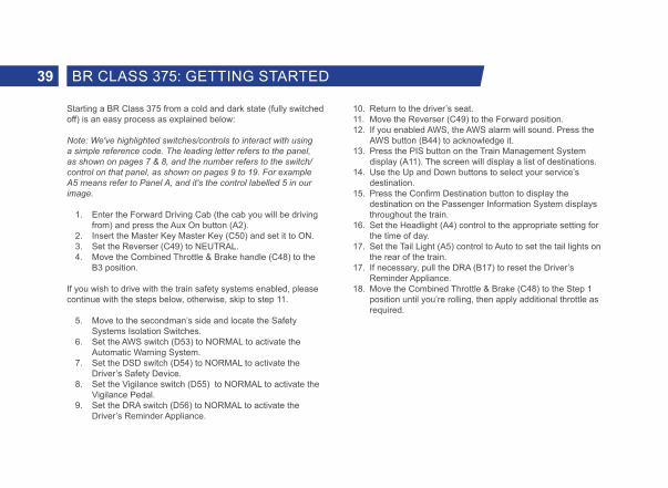
Starting a BR Class 375 from a cold and dark state (fully switched off) is an easy process as explained below:
Note: We've highlighted switches/controls to interact with using a simple reference code. The leading letter refers to the panel, as shown on pages 7 & 8, and the number refers to the switch/control on that panel, as shown on pages 9 to 19. For example A5 means refer to Panel A, and it's the control labelled 5 in our image.
1. Enter the Forward Driving Cab (the cab you will be driving from) and press the Aux On button (A2).
2. Insert the Master Key Master Key (C50) and set it to ON. 3. Set the Reverser (C49) to NEUTRAL. 4. Move the Combined Throttle & Brake handle (C48) to the
B3 position.
If you wish to drive with the train safety systems enabled, please continue with the steps below, otherwise, skip to step 11.
5. Move to the secondman’s side and locate the Safety Systems Isolation Switches.
6. Set the AWS switch (D53) to NORMAL to activate the Automatic Warning System.
7. Set the DSD switch (D54) to NORMAL to activate the Driver’s Safety Device.
8. Set the Vigilance switch (D55) to NORMAL to activate the Vigilance Pedal.
9. Set the DRA switch (D56) to NORMAL to activate the Driver’s Reminder Appliance.
10. Return to the driver’s seat.11. Move the Reverser (C49) to the Forward position.12. If you enabled AWS, the AWS alarm will sound. Press the
AWS button (B44) to acknowledge it. 13. Press the PIS button on the Train Management System
display (A11). The screen will display a list of destinations.14. Use the Up and Down buttons to select your service’s
destination.15. Press the Confirm Destination button to display the
destination on the Passenger Information System displays throughout the train.
16. Set the Headlight (A4) control to the appropriate setting for the time of day.
17. Set the Tail Light (A5) control to Auto to set the tail lights on the rear of the train.
17. If necessary, pull the DRA (B17) to reset the Driver’s Reminder Appliance.
18. Move the Combined Throttle & Brake (C48) to the Step 1 position until you’re rolling, then apply additional throttle as required.
39 BR CLASS 375: GETTING STARTED

1. On approach to the station, you should always manage your speed appropriately. The timing of the brake applications will need to be timed properly to ensure a smooth and stable stop. As such, you will need to think and act well ahead. Begin approximately 1 to 1.5 miles from the station by applying a 1 Bar reduction with the Combined Throttle & Brake Lever. Note this ‘braking point’ distance is influenced by numerous factors, such as the current speed of the train, the weight of the consist, the current grade and the conditions of the rails – it will be necessary for you to adjust your braking point accordingly.
2. The aim is to apply sufficient brake pressure once and only adjust it when you reach the start of the platform. As a general rule, you should always aim to be at no more than 25 mph depending on the platform length. For short platforms, you should aim to be at no more than 15 mph when you reach the start of the platform.
3. Move the Combined Throttle & Brake Lever to increase the brake pressure to around 2 Bar.
4. As your speed reduces below 10 mph, move the Combined Throttle & Brake Lever to 1 Bar to ensure the stop is smooth and does not introduce a sudden stop as the brake pads bind. Friction increases the slower your speed and easing off on the brake application will limit this.
5. Once the train has reached a full stop, move the Combined Throttle & Brake Lever to 3 Bar to secure the train.
USING A 3-STEP BRAKE CONTROL LEVER
The process for stopping at stations with a 3-step brake control, like that fitted to the BR Class 375) is largely identical as for a non-stepped control. However, depending on the railhead condi-tions, it is not necessary to begin slowing with a 1 Bar reduction. Trains with stepped brake control are typically fitted with Wheel Slip Protection (WSP) and can automatically manage the brake if wheel slip or slide is introduced during braking. The steps are as follows:
1. Begin by moving the Combined Throttle & Brake handle into the Step B2 position at your braking point. Should WSP be activated, do not move the handle and instead allow the system to command the brakes as necessary.
2. If braking does not appear to be sufficient, move the handle into Step B3.
3. As your speed reduces below 10 mph, move the handle into Step B1 to ensure the stop is smooth.
PASSENGER DOOR CONTROLS
Passenger entry and exit doors on each side can be operated independently i.e. either left side or right side. Simply press the Open Passenger Doors Left (CL375:B25 / CL395:A13) or Open Passenger Doors Right (CL375:B34 / CL395:E61) button.
To close the doors, press the Close Passenger Doors (CL375:B27/B32 / CL395:A15/E62) button.
40APPROACHING STATIONS & DOOR CONTROLS
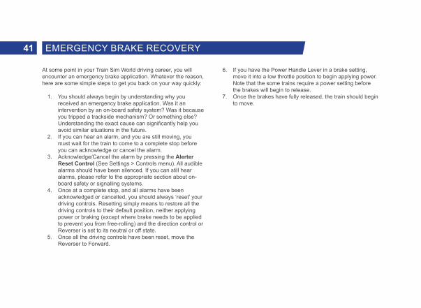
At some point in your Train Sim World driving career, you will encounter an emergency brake application. Whatever the reason, here are some simple steps to get you back on your way quickly:
1. You should always begin by understanding why you received an emergency brake application. Was it an intervention by an on-board safety system? Was it because you tripped a trackside mechanism? Or something else? Understanding the exact cause can significantly help you avoid similar situations in the future.
2. If you can hear an alarm, and you are still moving, you must wait for the train to come to a complete stop before you can acknowledge or cancel the alarm.
3. Acknowledge/Cancel the alarm by pressing the Alerter Reset Control (See Settings > Controls menu). All audible alarms should have been silenced. If you can still hear alarms, please refer to the appropriate section about on-board safety or signalling systems.
4. Once at a complete stop, and all alarms have been acknowledged or cancelled, you should always ‘reset’ your driving controls. Resetting simply means to restore all the driving controls to their default position, neither applying power or braking (except where brake needs to be applied to prevent you from free-rolling) and the direction control or Reverser is set to its neutral or off state.
5. Once all the driving controls have been reset, move the Reverser to Forward.
6. If you have the Power Handle Lever in a brake setting, move it into a low throttle position to begin applying power. Note that the some trains require a power setting before the brakes will begin to release.
7. Once the brakes have fully released, the train should begin to move.
41 EMERGENCY BRAKE RECOVERY

TRAIN SAFETY & IN-CAB SIGNALLING SYSTEMS5

43 AUTOMATIC WARNING SYSTEM (AWS)
The original concept of AWS was to provide the driver with anaudible and visual indication of whether a distant signal was atclear or caution. Should the driver fail to respond to a warning indication, an emergency brake application would be initiated.
Since the introduction of multi-aspect signalling, the majority ofsignals are fitted with AWS and provide a failsafe method to alert the driver to potentially dangerous conditions ahead such as a signal at caution or danger, some types of level crossing or a dramatic change in permissable speed.
ENABLING OR DISABLING AWS
The default state of the AWS system is disabled. To enable the system you must be seated in the driving seat and the train must be stationary. Use the Signalling Systems Enabled control (See Settings > Controls menu). Repeat to disable the system again.
OTHER CONTROLS
AWS can also be enabled/disabled via in-cab switches. See Pages 14, 18, 24 and 29 for the location of the in-cab switches.
COMPONENTS OF AWS
AWS has its own indicator known as a sunflower (shown opposite) which displays either an on or off indication. The on indication simply advises that the driver has acknowledged an alert.
GENERAL NOTES
Unlike some European systems, AWS cannot differentiate between different types of cautionary or dangerous signal aspects nor can it monitor speed. The responsibility remains in the driver's hands how to respond to such alerts and obey appropriate signalling and signage at the line side.
AWS typically consists of a magnet placed in the four-foot and preceeds a signal by a distance of typically 200 yards (180 metres), which is then energised when the signal is at clear. A train-mounted device then reads the state of the magnet and reports the state accordingly in the cab.
AWS is a fail-safe system in that the system remains operational and provides a warning even when the system fails or is unpowered.
In modern trains, AWS is typically interconnected with the Train Protection & Warning System (TPWS) as it provides additional protection in the form of overspeed (going too fast) and overrun (passing a signal at danger) protection alongside the basic operation of AWS.

44TRAIN PROTECTION & WARNING SYSTEM (TPWS)
The Train Protection & Warning System is used to stop the train by automatically initiating an emergency brake application if the train has:
- passed a signal at danger without permission to do so.- approached a signal at danger too fast.- approached a reduction in permissable speed too fast.- approached buffer stops too fast.
ENABLING OR DISABLING TPWS
TPWS is tied to the basic operation of AWS and when AWS is disabled, so is TPWS. See Enabling or Disabling AWS on the previous page for further instructions.
GENERAL NOTES
TPWS typically consists of one or more types of loop placed in the four-foot at the following locations:
- on passenger lines, at all main running signals capable of showing a stop aspect, including some stop boards which protect crossing or converging train movements.
- at any signal capable of showing a stop aspect on a non-passenger line, where that signal that protects a crossing of, or convergence with, a passenger line.
- at stop signals where conflicting movements could take place in the overlap of the next stop signal ahead.
- on the approach to a buffer stop at the end of passenger platforms.
- on the approach to permissable speed restrictions, where the permissible speed on the approach is 60 mph or more and the reduction in permissible speed is at least one third.
The loops are typically of two types, TSS (Train Stop System) and OSS (Overspeed Sensor System), and generally are placed to factor a number of variables such as the braking performance of trains and gradient of the line, among others.
Alongside the track equipment, on-train equipment reads the status of the track equipment and takes action to stop the train if it deems appropriate to do so such as in the case of overspeed (going too fast) or if it is about to overrun (go past) a signal at danger.
The TSS is a single loop placed ahead of the signal it is protecting and is energised when a signal is at danger. Should a train pass the loop, the emergency brakes are triggered.
The OSS consists of two loops, an arming loop and a trigger loop. The arming loop starts a timer and if a train passes a trigger loop within a designated time period (which indicates a train is overspeeding) the emergency brakes are triggered.

In and around London, the track is embedded with beacons that transmit information about signals and speed limits. The on-board receiver interprets the signals and displays information about the current expected speed along with lights and sounds that alert the driver if the train travels more than 5 km/h over the expected speed. If the driver doesn’t take action to reduce speed quickly enough, the system applies emergency braking.
ENABLING OR DISABLING KVB
The default state of the KVB system is disabled. To enable the system you must be seated in the driving seat and the train must be stationary. Use the Signalling Systems Enabled control (See Settings > Controls menu). Repeat to disable the system again.
OTHER CONTROLS
KVB can also be enabled/disabled via the in-cab switch. See Pages 8, 15 and 19 for the location of the in-cab switch.
COMPONENTS OF KVB
KVB has its own unit (shown opposite) which displays various indications and includes several controls that can be interacted with. The unit itself can be found on Panel D.
The functional elements as represented in Train Sim World are explained as follows:
1. Orange display warns of upcoming speed restrictions.2. KVB Shunt button.3. KVB Pass Danger button.4. Green display confirms when speed restrictions are
enforced.5. KVB Test button performs a self-test of the KVB Unit.6. V indicator advises when you are exceeding the current
speed restriction by 5 km/h or more.7. Enforced Braking Indicator advises when the system has
activated the emergency brake.8. Alert Indicator advises when an alert has been triggered by
KVB.9. Clear Light button clears the Alert Indicator.
The chart on the next page explains the various indications and how you should react.
45 KVB

The KVB system displays this signal when the maximum authorized speed is greater than 160 km/h.
The yellow P is displayed to warn of a reduction to 160 km/h. It’s followed by the green P when the reduction is enforced.
The yellow L is displayed to warn of a temporary speed reduction. It’s followed by the green L when the reduction is enforced.
The yellow double-zero is displayed to warn of an upcoming stop signal with an approach speed of 30 km/h. It’s followed by the green double-zero when the reduction is enforced.
Active speed control when authorized speed is below 160 km/h. When this is displayed, the driver must follow posted line speeds.
The yellow triple-zero is displayed to warn of an upcoming stop signal with an approach speed of 10 km/h. It’s followed by the green triple-zero when the reduction is enforced.
When the KVB system intervenes with an emergency brake application, the display shows this message.
46USING KVB

When the train is travelling on a high-speed line, signals and speed control are displayed in the cab in a specially designed display (Panel D). The current maximum speed and any upcoming speed reductions are displayed on this panel.
ENABLING OR DISABLING TVM-430
The default state of the TVM-430 system is disabled, to enable the system you must be seated in the appropriate driving seat and the train must be stationary. Use the Signalling Systems Enabled control (See Settings > Controls menu). Repeat to disable the system again.
OTHER CONTROLS
TVM-430 can also be enabled/disabled via the in-cab switch. See Pages 13 and 18 for the location of the in-cab switch.
USING TVM-430
With the arrival of high speed lines in the UK, the TVM (Transmission Voie-Machine, or track-to-train transmission) signalling system was introduced due to its proven success in France. Like the blocks in lower-speed areas, TVM-430 blocks are about 1,500 meters apart, but the track is embedded with a series of sensors that report the status of blocks well ahead of the distance visible to the driver. This allows the on-board computer systems to determine a safe speed for the train’s current location based on its stopping ability. TVM-430 works well on high speed lines where all of the equipment has similar characteristics because the spacing and timing of signals corresponds to the typical stopping distance of high speed trains.
TARGET SPEED INDICATORS
The on-board TVM-430 equipment makes the driver aware of the current maximum safe speed with an in-cab display system. As the train approaches a speed reduction, a stop, or a block occupied by another train, the TVM-430 display warns the driver to slow by displaying not only the upcoming required speed, but also a target speed that the driver needs to match to decelerate safely. If the driver stays above the pre-programmed deceleration curve by not reducing speed rapidly enough, the system applies the brakes.
The TVM-430 display provides a series of indications as described on the following page:
47 TVM-430

Authorisation to increase speed is indicated with white numbers on a green background. You must not exceed the speed displayed.
Warning for an upcoming reduced speed is indicated with black numbers on a white diamond background. If the speed of the block after the next one is lower, these numbers will flash.
A slower execution speed is indicated with white numbers on a black background. This is used when the current maximum speed for this train is lower than the line's maximum speed.
An upcoming stop is indicated with black zeros on a white diamond with a red background.
A full stop is indicated with three red squares.
TVM-430 essentially replaces the role of the lineside speed boards and signals. When travelling at speeds of in excess of 200 km/h, it is impossible, even for the most alert drivers, to reliably read the signs and signals at the side of the track. Instead, those indications are shown to you in the cab.
As you drive, upcoming changes in speed are displayed in the 'egg box', the aptly nicknamed TVM-430 display. If you are authorised to accelerate the train, you may do so if the indication is displayed as white numbers on a green background. If you are expected to decelerate the train, the indication will change to black numbers on a white diamond. If you are to continue deceleration to an even lower speed than is shown, the black numbers in the white diamond will flash on and off.
Each time the system updates, you'll hear a simple tone to draw your attention to it. Simply regard the values shown as the speed you need to reach, whether that's higher than your current speed or lower.
If you need to come to an immediate stop, three black zeroes on a white diamond on a red background will advise you to immediately brake your train to a stop. When you're within the range for a complete and full stop, three red squares will be shown.
48USING TVM-430

BRITISH RAILWAYSIGNALLING6

AB123
British colour light railway signals consist of one or more physical components or modules that form the basis of advising the driver on the state of the route ahead. The components are, from top to bottom:
Junction Indicator or Route Indicator typically mounted above the main aspect head.
Main Aspect Head (the example shown is a four-aspect type) which provides a visual representation of the state of the route ahead.
Signal Type Identifying plate advises what type of signal this is (the example shown is an automatic signal).
Signal Identification Plate advises the area this signal is situated in and its corresponding identification number.
The examples above show the appropriate aspects for four-aspect block signalling. The Advanced Caution aspect is used to enable greater braking distance for trains travelling at high speeds or that have heavy loads, and even in situations such as on steep downhill grades that is likely to require greater distances to stop.
Stop You must not proceed beyond this signal; the next block is occupied.
CautionProceed into the next block. Expect the next signal to be at Stop.
Advanced Caution Proceed into the next block. Expect the next signal to be at Caution.
Clear Proceed into the next block.
50BRITISH SIGNALLING: COLOUR LIGHT

For three-aspect signalling, these signals cannot display the Advanced Caution aspect. The meaning of each aspect is identical to those of four aspect signals.
For two-aspect signalling, these can only display the Clear and Stop aspect. However, care should be taken with two aspect signals as there can also be limited aspect and distant variants as shown above.
Stop You must not proceed beyond this signal; the next block is occupied.
CautionProceed into the next block. Expect the next signal to be at Stop.
Clear Proceed into the next block.
Stop You must not proceed beyond this signal; the next block is occupied.
CautionProceed into the next block. Expect the next signal to be at Stop.
Stop You must not proceed beyond this signal; the next block is occupied.
Clear Proceed into the next block.
Clear Proceed into the next block.
CautionProceed into the next block. Expect the next signal to be at Stop.
51 COLOUR LIGHT OVERVIEW
DISTANT SIGNALS
LIMITED ASPECT

Distant signals are explained further along in this guide. However, Limited Aspect signals are those that are incapable of displaying a Clear aspect and are therefore limited to ‘degraded’ aspects. Degraded essentially means - if Clear is the best possible aspect you can receive, then the aspect below that is Caution, which is worse than Clear and Stop is worse than Caution. These are called degraded aspects because each one degrades or slows the movements of trains.
52COLOUR LIGHT OVERVIEW
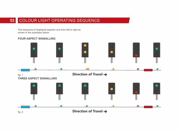
The sequence of displayed aspects runs from left to right as shown in the examples below:
FOUR ASPECT SIGNALLING
THREE ASPECT SIGNALLINGfig. 1
fig. 2
53 COLOUR LIGHT OPERATING SEQUENCE

TWO ASPECT SIGNALLING
In these diagrams, if you are the blue train, the five signals spaced between you and the red train would follow the sequence as shown in these examples. They also form a protection barrier between you and the red train. The empty space between each signal is called a block. Essentially, there are four empty blocks between you and the train in front. The distance between you and the train you are following is important as it should provide you with enough distance to bring your train to a complete stop when travelling at the maximum permitted speed of the line.
For a three-aspect signalling system, the number of blocks for braking would be reduced to three blocks. This means there is less braking distance between you and the train in front since three-aspect signals are incapable of displaying the Advanced Caution aspect. So, you can form the conclusion that the greater the number of main aspects a signal can display, the greater the distance between you and the train ahead and the greater the
overall braking distance and the safer it is.
For two aspect signalling, you can see that there is very little braking distance. In fact, you would be unaware you were following another train until you were in the block immediately behind it. Two aspect signalling is not commonly used on main lines and is usually used on slower branch lines with less traffic.
Typically, four-aspect signals are used where line speeds would be in excess of 100 mph. However, there may be instances where the line speed is lower but additional protection is required. For example, due to a junction with a preceding steep downhill section and therefore greater distance required for braking of heavier trains. It is also used to increase overall capacity as the more protection that is provided, the more trains can run on the same line.
fig. 3
54COLOUR LIGHT OPERATING SEQUENCE

Additionally, each buffer stop (the end of the track as found at the end of sidings or at a terminus station) is regarded itself as a Stop signal and therefore signals further back up the line would display the appropriate aspects.
Finally, for limited aspect signals, you would normally find these when on approach to terminus stations where the aspect is limited to Caution or stop to add additional protection for trains within the platforms.
Co-Acting Signals
Co-acting signals are smaller versions of the main aspect signals and give both short and long-distance sighting of a signal. A co-acting signal repeats the exact same aspect of the main aspect and are always the same type (colour light or semaphore) as the main signal. You will typically find them at stations where visibility of the main signal is obstructed or impossible to read when stopped in a platform.
55 COLOUR LIGHT OPERATING SEQUENCE

The examples above show the appropriate aspects for Upper-Quadrant signals (UQ), i.e. the signal arm raises into the upper quadrant of an arc in order to display its Clear aspect. Lower Quadrant signals are those that drop downwards but the meaning between each type is identical. For a Clear aspect (fig. 5), you should regard any indication that is at a 45-degree position and, for a Stop aspect (fig. 4), those indications that are at a horizontal position. Note that these signals are essentially only capable of displaying two aspects and you should regard them as such when considering speed and braking effort.
fig. 4 fig. 5
56BRITISH SIGNALLING: SEMAPHORE

Clear
Continue at the maximum permitted speed for your train or for the route that has been set. If the train is fitted with AWS, a clear bell or tone will sound as you pass over the magnet that is situated on approach to the signal.
Advanced Caution
For lighter trains that have good braking, you should continue at the maximum permitted speed and look out for the next signal which is likely to be at Caution. If you are in a heavy train, are travelling at or just below 125 mph or are descending a steep grade, you should begin braking as soon as you see the aspect with a 14.5 PSI (1 Bar) reduction with the Driver’s or Train Brake. If the train is fitted with AWS, a warning horn or tone will sound, as you pass over the magnet, that you must acknowledge.
Caution
All trains should be braking once this signal is in sight. If your speed is such that you are unlikely to stop before the next signal, increase your braking effort to 29 PSI (2 Bar) to further reduce your speed. The aim is to reduce your speed to around 25 mph well in advance of the Stop signal ahead. If the train is fitted with AWS, a warning horn or tone will sound, as you pass over the magnet, that you must acknowledge.
Stop
All trains must stop in advance of the signal. If the train is fitted with AWS, a warning horn or tone will sound, as you pass over the magnet, that you must acknowledge.
It is important that you bring your train to a stop as close to the signal as possible but ensure that you can safely read the displayed aspect from your seated position. Do not stop so close to the signal that you need to adjust your driving position in order to read the signal aspect. Also, do not stop so far away from the signal that there is an extended distance to cover before passing the signal, this may result in the rear of the train occupying the rear-most signal block and impacting the safe movement of trains behind you.
Once you have come to a complete stop, it is considered good practice to move the Driver’s or Train Brake into the full-service position to secure the train.
57 REACTING TO MAIN ASPECT SIGNALS

Distant signals, sometimes referred to as Related Signals, essentially provide advanced warning of the aspect being displayed on the next block signal (the signal it is related to). You are not required to take any action at distant signals, but they can be useful for providing extra braking distance when you have a heavy or fast train.
In the examples above, the top row of signals are displaying a Caution aspect. The bottom row are displaying a Clear aspect. These type of signals will show either a triangle or ‘R’ suffix on the identification plate as explained in the Identifying Signal Types section.
fig. 6
fig. 7
58DISTANT OR RELATED ASPECTS

When main aspect and distant signals are combined, they are effectively capable of displaying three aspects, as shown in the examples below. Combined semaphore signals are read from the top-most arm first and then the next lower arm, as explained below:
The signal on the left (fig. 8) both arms display a Clear aspect, so it is safe to proceed past this signal into the next block. This signal also advises that the next main signal is also displaying a Clear aspect, so it is also safe to proceed into that block too.
The centre signal’s (fig. 9) top-most arm displays a Clear aspect but the lower arm advises that the following main aspect signal is
displaying a stop aspect. You therefore need to regard this signal as Caution, you may pass this signal but be prepared to stop at the next signal.
The right signal’s (fig. 10) top-most arm displays a Stop aspect. In this situation, the distant arm drops to caution because that is the lowest degraded aspect it can display. You should therefore not pass this signal.
fig. 8 fig. 9 fig. 10
59 COMBINED MAIN ASPECT & DISTANT SIGNALS

Most colour light signals carry identification plates that aid the driver in understanding how they should regard the indication the signal is displaying. Understanding how to read the identification plate can be useful in determining what type of signal is providing you with instructions or guidance.
The identification plate is typically mounted to the post that carries the main signal aspect head. However, due to placement or clearance issues such as when signals need to be placed on the ground in stations, the identification plate may be mounted on top of the signal head. The identification plate can be broken up into three dedicated sections:
The upper part of the identification plate employs a form of code that advises the driver on what type of signal is deployed. In this instance, a three aspect banner repeater.
The alphanumeric characters AB 123 are the signal’s area code and signal identification number in that area.
The suffix characters further advises what type of signal is deployed. In this instance, the letters BR mean Banner Repeater.
Here are some other types of identification plates that are commonly used:
Signals that carry no type identification are called Controlled Signals (fig. 11). This means the signal is directly controlled by a signaller or controller.
The horizontal black band on a white background signifies that this is an automatic signal that sets its aspect based on the passage of trains and not by a signaller.
With the word “SEMI” added, this advises that this signal is semi-automatic and can be controlled by a signaller or set to automatic operation if required.
AB123BR
AB123
AB123
AB123
60IDENTIFYING SIGNAL TYPES

Slightly different to the three-aspect Banner Repeater shown in the previous example, the solid circle and “BR” suffix signifies this is a two-aspect Banner Repeater.
The white triangle signifies that this is a distant signal and can sometimes be displayed with or without the triangle or the “R” (Repeater) suffix, but never both.
The “CA” suffix indicates that this signal is a co-acting signal.
AB123BR
AB123
R
AB123CA
61 IDENTIFYING SIGNAL TYPES

Banner Repeater signals should be treated in exactly the same way as Distant/Repeater Signals. These signals are often used where visibility of the main signal is reduced or obstructed.
The horizontal band denotes the next main signal is displaying a stop aspect. You should be prepared to stop at the next signal.
The diagonal band denotes the next main signal is displaying a proceed aspect. Note that a proceed aspect can either be Clear, Advanced Caution or Caution. Most banner repeater signals can only display two aspects.
The diagonal band on a green background denotes the next main signal is displaying a Clear aspect. Note the distinction between Proceed and Clear. You will only find this on three aspect banner repeaters.
Position lights are subsidiary signals that grant on-sight movement authority to trains when a main aspect can’t be provided, such as in sidings or a yard.
This signal means stop. There may be an obstruction ahead and you should not proceed beyond this signal without permission to do so.
This signal also means stop. If you are shunting, you should not proceed beyond this signal as this is the outermost shunt limit.
Proceed on sight at caution toward the next train, signal or buffer stop, and be prepared to stop short of any obstruction.
This signal also means proceed on sight at caution.
This signal means stop.
62BANNER REPEATERS & POSITION LIGHTS

If the position-light is affixed below a main aspect signal, there may not be any indication provided as these indicators are incapable of displaying a red Stop aspect in the same way that Position-Lights do (previous page). If this indicator is unlit, you should always obey the main aspect. Typically, the position light below the main signal would be lit if movement authority is granted where the main aspect cannot provide an indication other than Stop (for example if the line ahead is occupied when coupling to vehicles in a station or siding). For these signals, you need to regard the signal as one indication even though there may be multiple aspects displayed:
Proceed at Caution toward the next train, signal or buffer stop, and be prepared to stop short of any obstruction.
Stop. You must not proceed beyond this signal; the next block is occupied.
CALLING ON / PROCEED ON SIGHT

RAILWAYSIGNS7

Alongside signals, there are some important signs to be aware of. Here are some of the examples you will find on Isle of Wight:
Maximum Permitted Speed
Speed signs on the CTRL or HS1 route are different than those you will find on the rest of the British railway network. Predominantly, speed is measured in km/h on the high speed lines. Speed signs are therefore presented differently. Those with a black background are in km/h and those with a white background are in mph.
The modern style of maximum permitted speed sign. You must not exceed the posted limit under any circumstances.
The “Morpeth Board” advises the driver that the maximum permitted speed will decrease ahead to the value shown on the sign. You should begin to slow to match this new speed before you reach the restriction ahead.
Whistle & Coasting Boards
The modern variant of the whistle board at which the driver must make a clear single loud tone on the horn if between the hours of 7:30 am and 11:30 pm. At some sites, particularly at crossings it will be necessary to use a loud two-tone horn. Between the hours of 11:30 pm and 7:30 am, drivers must use discretion in use of the horn and should use a low tone except when required to warn other users of the railway of your approach, loud tones can therefore be used for this purpose.
The coasting board advises that the driver may coast (travelling along without power applied) to a stopping point or significant speed reduction beyond the board.
65 RAILWAY SIGNS

Example Meaning
Provides advanced warning of an approaching power change over point.
Provides advanced warning of an approaching neutral section. For Javelin operation, there is no need to manage neutral sections as it is handled entirely automatically.
This sign marks the point where the neutral section ends.
Certain signs and signals are preceded by warning marker boards which count down as you approach. The signs are positioned at 100 metre intervals starting at 300 metres from the sign or signal.
66CTRL/HS1 TRACKSIDE SIGNS

Example MeaningThese signs mark the start of in-cab signalling (TVM-430) with the appropriate advanced warning as well as end of operation sign.
This sign marks the point where the rear of the train has passed beyond the current change section. Once this sign is reached, it is safe to raise the pantograph as the rear of the train has cleared the relevant overhead equipment.
On high speed lines, signals cannot be read reliably but the line still needs to be broken into blocks to increase overall capacity on the lines. Instead of signals, a series of marker boards are placed which mark the boundaries of these blocks. The yellow arrow points to the track or line it relates to. On high speed routes, this board is also accompanied with a 'N' or 'P' board to denote whether it is a non-passable or passable board.
Signs may also be accompanied with a position indicator lamp which enables on-sight movement authority. See pages 62 & 63 for more information.
67 CTRL/HS1 TRACKSIDE SIGNS

GENERALINFORMATION8

The Dovetail Forums are your one-stop destination for everything Train Simulator and Train Sim World related. We have an ever growing and vibrant community of train enthusiasts from all over the world, ranging from experienced railroad veterans to new players getting into the world of train simulation. So, if you haven’t already, why not sign up for an account today and join our community – we’d love to have you on board!
See more at: https://forums.dovetailgames.com
Dovetail Live is an online destination which enables players to interact with Dovetail’s products and each other in an environment tailored specifically to fans of simulation entertainment. Dovetail Live will evolve to become central to Train Sim World®, enriching the player experience in every way from offering rewards, building a community of likeminded players and helping every player find the right content to create their own perfect personal experience.
Signing up for Dovetail Live is completely voluntary. However, users that do sign up for it will receive exclusive benefits in the future.
See more at: https://live.dovetailgames.com
69 DOVETAIL LIVE

I have a problem downloading the Steam client, how do I contact them?
You can contact Steam Support by opening a customer service ticket at https://support.steampowered.com. You will need to create a unique support account to submit a ticket (your Steam account will not work on this page) and this will enable you to track and respond to any tickets you open with Steam.
How do I change the language of Train Sim World?
This is an easy process and will allow you to play Train Sim World in English, French, German, Spanish, Russian and Simplified Chinese. To change the language of Train Sim World, double-click on the Steam icon on your PC desktop, left click on ‘Library’, right click on ‘Train Sim World’, left click on ‘Proper-ties’, and finally left click on the Language tab and select your preferred language.
How do I reset my display screen size settings?
It is possible to change the display screen size settings for Train Sim World from within the game. Changing display screen size settings is done from the Settings menu in the Display tab.
For any questions not covered here, visit our knowledgebase at https://dovetailgames.kayako.com
70TROUBLESHOOTING GUIDE & HOW TO GET HELP

We would like to take a moment to express our gratitude to the following organisations and individuals who helped us to deliver this product:
Southeastern for their kind permission to represent their iconic brand and trains in Train Sim World.
71 CREDITS & ACKNOWLEDGEMENTS