South Tunnels and Sheppard West Station Environmental ... · Toronto-York Spadina Subway Extension...
43
Toronto-York Spadina Subway Extension Project Subway Station Design Services Contract No. A85-75F Sheppard West Station South Tunnels and Sheppard West Station Environmental Management Plan May 28, 2010 Toronto Transit Commission
Transcript of South Tunnels and Sheppard West Station Environmental ... · Toronto-York Spadina Subway Extension...

Toronto-York Spadina Subway Extension Project
Subway Station Design Services
Contract No. A85-75F Sheppard West Station
South Tunnels and Sheppard West Station
Environmental Management PlanMay 28, 2010
Toronto Transit Commission

Toronto-York Spadina Subway Extension Project
South Tunnels and Sheppard West Station Environmental Management Plan
Page 1
Table of Contents 1. INTRODUCTION ................................................................................................................................................. 3
1.1 Objectives .................................................................................................................................................... 3 1.2 Project Overview – Sheppard West Station ................................................................................................ 3 1.3 Project Overview – South Tunnels Contract ............................................................................................... 4 1.4 Existing Environmental Conditions .............................................................................................................. 4 1.5 Applicable Legislation and Guiding Principles ............................................................................................ 5
1.5.1 Federal .................................................................................................................................................... 5 1.5.2 Provincial ................................................................................................................................................. 5 1.5.3 Municipal Governments and Local Authorities ........................................................................................ 5
1.6 Roles and Responsibilities .......................................................................................................................... 6 1.6.1 Documentation and Internal Communication .......................................................................................... 6 1.6.2 Environmental Management Training ..................................................................................................... 8 1.6.3 Monitoring Responsibilities...................................................................................................................... 8 1.6.4 Notification of Adaptive Measures Implementation ................................................................................. 8
1.7 Reference Documents................................................................................................................................. 9 2. CONSTRUCTION OVERVIEW .......................................................................................................................... 10
2.1 Station Box Construction ........................................................................................................................... 10 2.2 Tunnel and Station Mobilization Construction Areas ................................................................................ 10 2.3 Launch Shafts ........................................................................................................................................... 10 2.4 Extraction Shafts ....................................................................................................................................... 10 2.5 Emergency Exit Buildings (EEB) ............................................................................................................... 10 2.6 Tunnelling .................................................................................................................................................. 11 2.7 Cross Passages ........................................................................................................................................ 12
3. PROACTIVE MITIGATION MEASURES .......................................................................................................... 13 3.1 Groundwater Management ....................................................................................................................... 14
3.1.1 Dewatering ............................................................................................................................................ 14 3.1.2 Monitoring Well Protection and Decommissioning ................................................................................ 16
3.2 Erosion and Sediment Control .................................................................................................................. 17 3.3 Surface Water Runoff Management .......................................................................................................... 17
3.3.1 Sheppard West Station Box .................................................................................................................. 18 3.3.2 South Tunnels ....................................................................................................................................... 18
3.4 Aquatic Habitat Management .................................................................................................................... 18 3.4.1 Water Quality ......................................................................................................................................... 20 3.4.2 Thermal Changes .................................................................................................................................. 20 3.4.3 Stream Erosion (sedimentation) ............................................................................................................ 20
3.5 Vegetation Protection ................................................................................................................................ 20 3.5.1 Tree Protection Zones ........................................................................................................................... 20 3.5.2 Tree Removal ........................................................................................................................................ 21 3.5.3 Trimming/Pruning/Root Cutting ............................................................................................................. 21
3.6 Wildlife Protection ...................................................................................................................................... 21 3.6.1 Breeding Birds ....................................................................................................................................... 22
4. MONITORING AND ADAPTIVE MANAGEMENT PLANS ............................................................................... 23 4.1 Groundwater Monitoring ............................................................................................................................ 25
4.1.1 Water Table Drawdown ......................................................................................................................... 25 4.2 Erosion and Sediment Control .................................................................................................................. 27 4.3 Surface Water Runoff Management .......................................................................................................... 28
4.4 Aquatic Habitat Management .................................................................................................................... 29 4.4.1 Surface Water Temperature .................................................................................................................. 29 4.4.2 Aquatic Habitat & Fish Response ......................................................................................................... 29
4.5 Vegetation Protection ................................................................................................................................ 31 4.6 Wildlife Protection ..................................................................................................................................... 31
4.6.1 Breeding Birds ....................................................................................................................................... 31 5. CONSTRUCTION CONTINGENCY PLANS ..................................................................................................... 32
5.1 Spill Response Plan .................................................................................................................................. 32 5.1.1 Minor Spills ............................................................................................................................................ 32 5.1.2 Major Spills ............................................................................................................................................ 32 5.1.3 General Spill Response Protocols ........................................................................................................ 33
5.2 Severe Weather ........................................................................................................................................ 34 5.3 Dewatering Malfunction ............................................................................................................................. 34 5.4 Contaminated Groundwater into Excavation ............................................................................................ 35 5.5 Handling, Treatment and Disposal of Surface Water Issues .................................................................... 35
List of Tables Table 1-1 – Summary of Sensitive Ecological Receptors ............................................................................................4 Table 1-2 - Monitoring Responsibilities during Construction ......................................................................................8 Table 3-1 – Construction Activities, Associated Construction Areas and their Required Proactive Mitigation ........ 13 Table 3-2 – Dewatering ZOI and Estimated Dewatering Rates ................................................................................ 16 Table 3-3 – Storm Sewer Outfall Locations .............................................................................................................. 16 Table 3-4 – Summary of Thermal and Erosion Assessment .................................................................................... 19 Table 3-4 – Tree Protection Zones for City-owned and Private Trees ..................................................................... 20 Table 4-1 – Monitoring Plan and Associated Baseline, Trigger and Alarm Values .................................................. 24 Table 4-2 – Dewatering Monitoring Details ............................................................................................................... 26 Table 4-3 – Monitoring for Erosion and Sediment Control Measures ....................................................................... 27 Table 5-1 – Minor Non-Reportable Spills under Classification and Exemption of Spills Regulation ........................ 32 Table 5-2 – Reportable Spill Exemption Limits ......................................................................................................... 33 Table 5-3 – Major Spill Contingency Contacts .......................................................................................................... 33
List of Figures Figure 1-1 – Environmental Monitoring Documentation and Reporting Protocol Summary ........................................7 Figure 2-1 – Diagram of Earth Pressure Balance Tunnel Boring Machine ............................................................... 11 Figure 3-1 – Zone of Influence Map .......................................................................................................................... 15 Figure 4-1 – Discharge Water Action Plan – Municipal Sanitary and Storm Sewer ................................................. 25 Figure 4-2 – Area of Influence Dewatering Action Plan ............................................................................................ 26 Figure 4-3 – Erosion and Sediment Control Action Plan .......................................................................................... 28 Figure 4-4 – Surface Water Management Action Plan ............................................................................................. 29 Figure 4-5 – South Tunnels Storm Sewer Outfalls Map ........................................................................................... 30
List of Appendices Appendix A – Environmental Inspection Log
Appendix B – Weekly Summary Report template
Appendix C – Incident Follow-up Report

Toronto-York Spadina Subway Extension Project
South Tunnels and Sheppard West Station Environmental Management Plan
Page 2
List of Abbreviations AST – Aboveground Storage Tank
CALA – Canadian Association for Laboratory Accreditation
CAA – Conservation Authorities Act
CEAA – Canadian Environmental Assessment Act
CEPA – Canadian Environmental Protection Act
CESR – Classification and Exemption of Spills Regulation (O.Reg. 675/98)
CSA – Canadian Standards Association
DEPTHS – Double Ended Pocket Track Housing Structure
DFO – Fisheries and Oceans Canada
EAA – Environmental Assessment Act (Provincial)
EATP – Environmental Awareness Training Program
EEB – Emergency Exit Building
EMP – Environmental Management Plan
EPA – Environmental Protection Act (Ontario)
EPBM – Earth pressure balance tunnel boring machine
ESA – Environmental Site Assessment
ESC – Erosion and Sediment Control
ETR – Express Toll Route
FRP – Fibre-reinforced polymer
GGHACA – Greater Golden Horseshoe Area Conservation Authorities
GTA – Greater Toronto Area
HASP – Health and Safety Plan
HDPE – High Density Polyethylene
MOE – Ministry of the Environment
MSDS – Material Safety Data Sheet(s)
OHSA – Ontario Health and Safety Act
O. Reg. – Ontario Regulation
OWRA – Ontario Water Resources Act
PID – Photoionization Detector
PPE – Personal Protective Equipment
PPUDO – Passenger Pick Up and Drop Off
PTTW – Permit to Take Water
PWQO – Provincial Water Quality Objectives
SAC – Spills Action Centre
SEM – Sequential Excavation Method
SOE – Support of Excavation
SPGP – Sleeve Port Grout Pipe
SRK – Spill Response Kit
SWM – Surface water management
TBM – Tunnel Boring Machine
TCLP – Toxicity Characteristic Leaching Procedure
TDGA – Transportation of Dangerous Goods Act
TKN – Kjeldahl Nitrogen
TMP – Traffic Management Plan
TPZ – Tree Protection Zone
TRCA – Toronto and Region Conservation Authority
TSSA – Technical Standards and Safety Act
TTC – Toronto Transit Commission
TYSSE – Toronto-York Spadina Subway Extension
VCC – Vaughan Corporate Centre
VL – Volume Loss
WHMIS – Workplace Hazardous Materials Information System
WRWP – Waste Reduction Work Plan
YRT – York Region Transit
ZOI – Zone of Influence
DBH – diameter at breast height
mbgs – metres below ground surface
m2 – metres squared

Toronto-York Spadina Subway Extension Project
South Tunnels and Sheppard West Station Environmental Management Plan
Page 3
1. INTRODUCTION
The Toronto Transit Commission (TTC) has elected to undertake the completion of the Toronto-York Spadina Subway Extension (TYSSE) Project, which involves the extension of the Spadina Subway line from its existing terminus at Downsview Station in Toronto, Ontario to the Vaughan Corporate Centre in the City of Vaughan, Ontario. A total of six new stations will be constructed and associated tunnelling will be completed as part of the Subway Extension Project, including: Sheppard West Station, Finch West Station, York University Station, Steeles West Station, Highway 407 Station, and the Vaughan Corporate Centre Station (VCC). The goal of this effort is to improve the efficiency of public transportation in the Greater Toronto Area (GTA) and improve intermodal connections for passengers who use public transportation.
This Environmental Management Plan (EMP) has been developed to protect the environment during activities associated with the construction of the Sheppard West Station and the South Tunnels contract, which includes: the station box construction at the Sheppard West Station, tunnelling works from Downsview Station to Finch West Station, and development and implementation of landscaping design plans. The Sheppard West Station is located west of Dufferin Street and east of Keele Street in the City of Toronto, Ontario. Three additional EMPs for other elements of the TYSSE Project will be provided under separate cover:
1. North Tunnels and Highway 407 Station EMP 2. York University Woodlot EMP (Finch West Station, York University Station and Steeles West
Station) 3. Vaughan Corporate Centre Station EMP
The goal of the EMP is to communicate the environmental efforts that will be required from all Project participants and stakeholders during the South Tunnels and Sheppard West Station Contract to manage and minimize potential environmental impacts. As the proponent, the TTC is required to complete an EMP, as indicated in the Environmental Assessment Compliance Monitoring Program report, dated December 2008.
1.1 OBJECTIVES
The overall objective of the EMP is to provide a comprehensive strategy for ensuring compliance with the relevant environmental legislation, policies and permitting requirements, to provide project-wide environmental guidelines, and to ensure that the environment is protected throughout the life of the Project.
The specific objectives of the EMP are to:
Clearly state the environmental philosophy to be followed on the Project and provide direction to action to avoid delay in identifying and addressing ecological impacts.
Set the appropriate environmental objectives and framework and identify the relevant legislative, regulatory and approval requirements.
Identify applicable mitigation measures and follow-up requirements during the Project.
Establish contingency and response procedures related to the discovery of unexpected site conditions.
Establish clear roles and responsibilities for the Commission‟s Representative (TTC) and Contractor(s), including work accountability and institution of reporting protocols with respect to environmental issues.
Require the implementation of environmental awareness training to ensure that all on-site personnel understand the importance of environmental protection, the causes of environmental damage, proper environmental protection practices and their obligations to ensure that the environment is protected.
Establish an adaptive monitoring and management program to verify that the environmental protection measures outlined in the EMP and associated documents are being properly implemented and maintained and are effective.
Ensure that proper records are maintained to monitor the effectiveness of the EMP.
Establish a process for analyzing the results of inspection and monitoring and reviewing the results with management in a timely manner to ensure rapid response to issues.
Ensure safe, rapid and effective response to unexpected emergency situations.
This EMP applies to active construction activities (i.e. mobilization, construction and demobilization) and the post-construction recovery period. The post-construction recovery period is the time immediately following the completion of construction activities in which site conditions will be monitored until conditions have stabilized (i.e. returned to pre-construction levels or anticipated post-construction conditions).
This EMP does not provide long term monitoring requirements for the period following the post-construction recovery period. Long term monitoring plans shall be developed under separate cover and are not the current responsibility of the South Tunnel and Sheppard West Station Contractor.
If permits issued to the Contractor to complete construction works entail long-term monitoring commitments, the Contractor may be required to complete long-term monitoring in accordance with said permit(s). This would involve a revision in the Contractor‟s scope and would require amendments to this EMP or the development of an EMP under separate cover. If the permit is transferable, the TTC may enter into an agreement with the Contractor to transfer the permit for long-term monitoring once active construction activities are complete.
1.2 PROJECT OVERVIEW – SHEPPARD WEST STATION
The scope of work for the Sheppard West Station is outlined in detail in the design specifications. The following overview is provided:
1. Design and construction of excavation shoring for the station box structure, including the construction of temporary structures at the north and south end of the excavation to enable the insertion of and operation of Tunnel Boring Machines (TBM);
2. Selection, design and maintenance of a dewatering system to reduce groundwater pressure and lower groundwater levels for a stable, undisturbed and substantially dry sub-grade;
3. Management of soil stockpile areas and disposal; 4. Construction of the TTC subway station and YRT/GO Terminals; and, 5. Acquisition of all necessary permits and documentation and the provision of all required services
and instrumentation.

Toronto-York Spadina Subway Extension Project
South Tunnels and Sheppard West Station Environmental Management Plan
Page 4
1.3 PROJECT OVERVIEW – SOUTH TUNNELS CONTRACT
The scope of work for the South Tunnels contract is outlined in detail in the design specifications. The following overview is provided:
1. The advancement tunnelling by TBM between Sheppard West Station and Downsview Station to the south and to Finch West Station to the north with associated construction of precast tunnel liner, launch shafts, extraction shafts, emergency exit buildings and cross-passages;
2. TBM maintenance, settlement monitoring, and selection of conditioning agents and tunnel grouting as per contract documents and design specifications;
3. Selection, design and maintenance of a dewatering system to reduce groundwater pressure and lower groundwater levels for a stable, undisturbed and substantially dry sub-grade (in emergency exit buildings and cross-passages, as required);
4. Management of spoil materials including drying and/or mixing areas; and, 5. Acquisition of all necessary permits and documentation and the provision of all required services
and instrumentation.
1.4 EXISTING ENVIRONMENTAL CONDITIONS
Existing conditions of the natural environment within and adjacent to TYSSE construction areas and areas located within dewatering ZOI‟s were assessed to document baseline conditions as well as to identify the presence/absence of significant or sensitive environmental receptors The results of these assessments would identify key ecological receptors that would require monitoring during project activities. The following table summarizes the key ecological receptors associated with this project.
Table 1-1 – Summary of Sensitive Ecological Receptors
Adjacent to Construction
Footprint
Within ZOI
Receiver of Groundwater
Discharge Details
Wetlands NI NI NA -
Woodlands NI NI NA -
Aquatic Habitat NI NI
*Dufferin Creek, Black Creek
Wildlife Habitat NI NI NA -
Endangered and Threatened
Species Habitat NI NI NA
-
ANSI’s or ESA’s NI NI NA -
*If groundwater is discharged to the municipal storm sewer
Station Box NA – Not Applicable
Tunnel Alignment NI – None Identified
The Sheppard West Station site, which includes Launch Shafts LS-4 and LS-5, as well as Cross Passage 2 (CP-2), is described as on old field meadow mixed with small amounts of woody growth.
More specifically, the site consists of four vegetation communities, including dry-fresh mixed meadow, cattail graminoid mineral meadow marsh, dry-fresh deciduous shrub thicket and dry-fresh deciduous woodland.
The Cross Passage 3 (CP-3) site is within an old field meadow with pockets of meadow marsh and scattered woody shrubs and trees. The majority of the area is a dry-moist Old Field Meadow (CUM1-1) with small areas of Reed Canary Grass Mineral Meadow Marsh and scattered, immature, naturally regenerating trees.
No provincially or locally significant wetlands, areas of natural or scientific interest (ANSI‟s), environmentally sensitive areas (ESA‟s) or aquatic habitat were located within or adjacent to the Station site, the CP-3 site as well as within the ZOI‟s of these sites. In addition, no rare or sensitive species habitat or significant wildlife habitat were identified. The value of habitat connectivity is limited as there are no associated habitat features connected to these sites. Adjacent lands to the sites and lands within the sites‟ ZOI‟s are comprised of similar habitat described above as well as urban development. In summary, no ecological receptors were identified adjacent to the Station or CP-3 sites, nor within the ZOI‟s.
All of the remaining TYSSE construction areas, (extraction shafts ES-4 and ES-5, emergency exit buildings EEB-1, EEB-2 and EEB-3 and cross-passages CP-1 and CP-4) and areas located within dewatering ZOI‟s have been assessed for any significant or sensitive ecological receptors. The areas are all built-up residential or commercial areas with maintained lawn with planted and maintained street trees.
If the municipal storm sewer system is selected as the location for groundwater discharge, the water will ultimately flow into nearby watercourses, including Black Creek and Dufferin Creek, further identifying these features as ecological receptors. These watercourses are both highly urbanized systems that experience flash short term high flows from storm water runoff. As storm water is the main source of flow in these systems, the Creeks are considered to have degraded water quality. They are also classified as warm water fish habitat where only tolerant species are present.
Dufferin Creek‟s stream flow originates from a stormwater sewer outfall located approximately 1km upstream of the West Don River. A fish barrier is present at the Dufferin Street crossing (approx. 0.5km upstream of West Don River) with the presence of a large double box culvert that is perched approximately 2m on the downstream side. Downstream of this barrier is the G. Ross Lord dam. Periodically, during high flow periods as such experienced after a large rain event, the dam will create back flow and pooling, resulting in the formation of the G. Ross Lord reservoir. It is also likely that back flow also raises water levels in Dufferin Creek as stream gradient is very low in this area. The presence of the 2m barrier at Dufferin Street is also likely present to prevent the back flow from moving beyond this point. It is expected that fish are not present within the reach from this fish barrier at Dufferin Street upstream to the stormwater outfall. Downstream of the fish barrier, fish are able to migrate from the West Don River and the G. Ross Lord reservoir. TCRA fish collection records for the area immediately downstream of Dufferin Street confirm the presence of a single species, Blacknose Dace (Rhinichthys atratulus). Fish community data present for the West Don in a reach located upstream of the Dufferin Creek confluence include Brown Bullhead (Ameiurus nebulosus), Common Carp (Cyprinus carpio), Pumpkin Seed (Lepomis gibbous), Rock Bass (Ambloplites rupestris) and White Sucker (Catostomus commersonii). All are generally tolerant species and are expected to migrate into Dufferin Creek during periods of sufficient flow.
Black Creek is part of the larger Humber River watershed and is managed for darter species under the Humber River Fisheries Management Plan (HRFMP, 2004). The fish community of Black Creek is typical of a warm water system. Dominant species include White Sucker (Catostomus commersonii),

Toronto-York Spadina Subway Extension Project
South Tunnels and Sheppard West Station Environmental Management Plan
Page 5
and Creek Chub (Semotilus atromaculatus). Less abundant species include Blacknose Dace (Rhinichthys atratulus), Pumpkinseed (Lepomis gibbous), and Bluegill (Lepomis macrochirus).
The following table summarizes the ecological receptors associated with this project.
1.5 APPLICABLE LEGISLATION AND GUIDING PRINCIPLES
In order to undertake environmental protection measures effectively and competently, Contractor(s) must be knowledgeable of the environmental legislation and legal requirements that are applicable to the Project scope. The following Federal, Provincial and municipal regulations, by-laws and guidelines direct the policies in this EMP and must be adhered to throughout the implementation of the Project undertaking. Best management principles must also be considered, although they are not legally binding.
1.5.1 Federal
The federal legislation that applies to this work includes, but not limited to, the following:
Legislation Regulations/Standards/Guidelines
Canadian Environmental Assessment Act
(CEAA), S.C. 1992, c. 37, Consolidated
Statutes of Canada
And associated regulations.
Dangerous Goods Transportation Act (TDG) And associated regulations.
Canadian Environmental Protection Act
(CEPA)
And associated regulations.
Federal Fisheries Act, Fisheries and Oceans
Canada (DFO)
Section 36, Subsection 3
Section 37, Subsection 1
And associated regulations.
Migratory Birds Convention Act* Migratory Birds Regulations
* Bird migration plans will be completed under separate cover, as required
Pursuant to Section 35 of the Fisheries Act, the Toronto and Region Conservation Authority (TRCA) has a Level 3 agreement with the Department of Fisheries and Oceans (DFO) which grants them the authority to review proposed work plans on behalf of DFO, to determine the potential for harmful alterations, disruptions or destructions of fish habitat (HADD) within their jurisdiction. Through a review of this EMP, the TRCA shall determine whether the proposed mitigation and monitoring measures related to the protection of fish and fish habitats are appropriate given the project works and issue a Letter of Advice with respect to their findings. The Letter of Advice shall confirm that the EMP protocols are appropriate and if employed as described, the project will not result in negative impacts to fish and fish habitat. Any additional mitigative measures will also be identified as required.
1.5.2 Provincial
The Provincial legislation that applies to this work includes, but not limited to, the following:
Legislation/Department Regulations/Standards/Guidelines
Environmental Assessment Act (EAA),
R.S.O. 1990, c. E.18, Consolidated Statutes
of Ontario
Transit Projects and Greater Toronto Transportation Authority
Undertakings, O. Reg. 231/08
Environmental Protection Act (EPA) Soil, Ground Water and Sediment Standards for Use Under
Part XV.1 of the Environmental Protection Act, March 2004
and amendments (O. Reg. 511/09)
General - Waste Management, R.R.O. 1990, Reg. 347
Waste Audits and Waste Reduction Work Plans, O. Reg.
102/94
Industrial, Commercial and Institutional Source Separation
Programs, O. Reg. 103/94
Classification and Exemption of Spills and Reporting of
Discharges, O. Reg. 675/98
Records of Site Condition - Part XV.1 of the Act, O. Reg.
153/04 and amendments.
Technical Standards and Safety Act (TSSA) And associated regulations.
Ontario Water Resources Act (OWRA) Wells, R.R.O. 1990, O. Reg. 903
And associated regulations.
Occupational Health and Safety Act (OHSA) Construction Projects, O. Reg. 213/91
And associated regulations.
Water Management Policies, Guidelines ,
Provincial Water Quality Objectives of the
Ministry of Environment and Energy (MOEE)
Water Management Policies, Guidelines, Provincial Water
Quality Objectives of the Ministry of Environment and Energy,
Table 2 – Table of PWQOs and Interim PWQOs, July, 1994
Ontario Ministry of Transportation Ministry of Transportation Ontario Drainage Management
Manual, 1997
1.5.3 Municipal Governments and Local Authorities
During the construction works, water discharges to the municipal sewer system must meet the requirements of the City of Toronto Municipal Code regarding Sewers (Chapter 681), as appropriate. The Contractor must obtain all necessary permits prior to construction works. Permits related to surface water discharges to storm sewer or a watercourse must also encompass contingency flows (i.e. storm flows etc.).
Project works must comply with the Conservation Authorities Act (CAA) Section 28-Toronto Region Conservation Authority Ontario Regulation 166/06: Development, Interference with Wetlands and Alterations to Shorelines and Watercourses Regulation. If a permit is issued by TRCA under this policy,

Toronto-York Spadina Subway Extension Project
South Tunnels and Sheppard West Station Environmental Management Plan
Page 6
all requirements of the permit must be complied with. As indicated in Section 1.5.1, the TRCA has authority to review project plans on behalf of DFO to determine the potential for a HADD of fish and fish habitat under the federal Fisheries Act. Through this review, the TRCA may issue a Letter of Advice, which must be complied throughout construction activities.
In addition, erosion and Sediment Control (ESC) measures on all construction sites will be designed as per the Erosion and Sediment Control Guideline for Urban Construction, December 2006 (ESC Guideline), prepared by the Greater Golden Horseshoe Area Conservation Authorities (GGHACA). All necessary permits must be obtained from Local Authorities.
1.6 ROLES AND RESPONSIBILITIES
While the overall management of the Project is the responsibility of the TTC, all retained representatives of the TTC, Contractor(s) and Sub-Contractors share responsibility for maintaining proper communication, reporting and documentation protocols during the Project undertaking.
TTC
The TTC is the overall Project Coordinator. The progress of the completion of the Project is overseen by the TTC, which will manage the overall Project schedule through appointed site representatives.
Commission‟s Representative
The TTC will appoint a supervisory representative for the Project to ensure that the Project is operating in conjunction with the Design Plans and Drawings, this EMP and other Project requirements and environmental protection plans (i.e. Traffic Management Plan, Erosion and Sediment Control Plan, Soil and Groundwater Management Strategy). The Commission‟s Representative must be notified of any potentially contaminated materials or substances that pose a hazard to site personnel or the environment or that may cause job delays or otherwise impact the completion of the work. The Commission‟s Representative will be consulted on all on-site decisions regarding the Project.
Contractor(s) and Sub-Contractor(s)
The Contractor(s) and Sub-Contractors are required to complete the works as outlined in the Design Specifications and associated contract documents, including the implementation of appropriate environmental controls. The Contractor shall retain a full time Environmental Manager to inspect the work site to ensure that the Contractor(s) and subcontractor(s) are in compliance with environmental control measures and procedures. The Contractor‟s Environmental Manager will be responsible for monitoring the condition of construction work areas. The Contractor‟s Environmental Manager is also required to complete the appropriate monitoring and reporting documentation, as provided in this EMP.
Environmental Manager(s)
The Environmental Manager(s) is retained by the Contractor to conduct confirmatory environmental monitoring and testing in accordance with this EMP and associated environmental regulations to ensure that the Project is not negatively impacting the natural environment. The Environmental Manager has a responsibility to advise the Contractor of any suspected or confirmed environmental issues or unsafe working environments. The Environmental Manager or their designate must be on-site during all intrusive activities and when any activities are being completed that may potentially cause an adverse affect to the natural environment. To the extent reasonable, the Environmental Manager must be reachable at all times. The Environmental Manager may take on additional responsibilities to those
mandated in this EMP at the discretion of the Contractor (i.e. health and safety); however, additional duties assigned to the Environmental Manager shall not impede the Environmental Manager‟s ability to competently oversee the procedures and requirements of this EMP.
The Environmental Manager shall:
a) Conduct inspections of mitigative measures throughout the day during periods of active construction activity.
b) Prepare for inactive or shutdown periods, including weekends or holidays, by inspecting the site‟s environmental protection measures.
c) Inspect the construction site daily during inactive periods when inclement weather or other potential issues may impact the environmental protection measures implemented on the site.
d) Inspect the work site after large precipitation events (>20mm in 24 hrs). e) Report any required environmental control changes or repairs to damaged mitigation measures
to the Contractor without delay and suggest measures to improve the effectiveness of existing devices, measures and systems.
The qualified Environmental Manager retained by the Contractor must meet the following criteria:
Licensed as, or supervised by, a Professional Engineer(s) in Ontario with the appropriate discipline for environmental controls or similar environmental professional (i.e. Professional Geoscientist) registered as a Qualified Person in the Province of Ontario;
Minimum two years environmental inspection experience; Familiar with the Greater Golden Horseshoe Area Conservation Authorities Erosion and
Sediment Control for Urban Construction Guidelines; Familiar with various sediment and erosion control techniques; and, Familiar with groundwater and surface water monitoring techniques.
Fisheries Biologist(s)
A Fisheries Biologist(s) must be retained by the Contractor on an as-needed basis (under a Standing Agreement established for the life of the contract) to carry out fisheries and aquatic biology related monitoring and assessments in partnership with the Environmental Manager and in accordance with this EMP and environmental regulations to ensure protection of the aquatic environment. The Fisheries Biologist has a responsibility to advise the Environmental Manager and the Contractor of any suspected or confirmed biological or environmental issues immediately.
The qualified Fisheries Biologist retained by the Contractor must meet the following criteria:
Minimum two years experience as a fisheries biologist; Technical diploma and/or bachelor‟s degree in biology or related discipline; and, Familiar with monitoring fish habitat quality.
1.6.1 Documentation and Internal Communication
All organizations working on the Project share responsibility in reporting findings with respect to on-site environmental conditions. A summary figure with respect to reporting and documentation protocols of the Contractor‟s Environmental Manager is provided at the end of this section (Figure 1-1), and responsibilities are described in detail below:

Toronto-York Spadina Subway Extension Project
South Tunnels and Sheppard West Station Environmental Management Plan
Page 7
TTC
The TTC is ultimately responsible for ensuring that environmental protection procedures are being implemented during the course of construction activities. If the TTC is notified by the Commission‟s Representative that environmental mitigation measures have not been implemented according to the EMP and legislative requirements, the TTC shall investigate the issue.
Commission‟s Representative
The Commission‟s Representative is responsible for collecting and reviewing all of the Contractor(s) Environmental Inspection Logs (EILs) and weekly summary reports (provided in Appendix B). In the event that repairs or improvements are required to environmental controls, devices, procedures or systems, as identified in the EIL, the Commission‟s Representative shall follow-up on the implementation of mitigative measures and request an Incident Follow-up Summary (provided in Appendix C) from the Contractor if one is not provided within a week of the incident.
If the review of documentation received by the Contractor(s) reveals that procedures as outlined in this EMP have not been followed, the Commission‟s Representative shall investigate and determine the cause of non-compliance, shall convey to the Contractor that new mitigation measures are required.
If confirmatory environmental audit monitoring or observations by the Commission‟s Representative indicate potential concerns with respect to environmental controls implemented by the Contractor, the Commission‟s Representative will distribute the monitoring results to the Contractor immediately and ensure that the Contractor has employed the appropriate mitigative measures.
Contractor(s), Contractor(s) and Sub-Contractor(s)
Through their Environmental Monitor, the Contractor(s) is responsible for completing the appropriate on-site documentation to ensure compliance with environmental protection procedures. The Contractor must ensure that the Environmental Manager is completing their required duties as set out in this EMP. The Contractor(s) Environmental Manager shall:
a) Record all observations and findings daily in an EIL (Appendix A) and report any immediate environmental concerns to the Contractor and Commission‟s Representative to ensure they are resolved.
b) Clearly identify any required repairs or improvements on the EIL and provide an estimation of the urgency of the repair or improvement with respect to protecting the environmental condition of the receptor.
c) Keep a copy of the EILs on site. d) Submit a copy of the daily EILs with a weekly summary report (Appendix B) to the Commission‟s
Representative within 72 hours of the last working day of the week (i.e. if work week ended on a Friday, EILs and summary report must be submitted on Monday).
If immediate environmental concerns with respect to construction activities or associated with site activities are identified, the Contractor‟s Environmental Manager shall:
a) Report the incident to the Contractor and work with the Contractor to resolve the issue. b) Verify whether proper procedures had been followed prior to the incident. If it is discovered that
the issue has occurred despite proper implementation, review the relevant procedures with the Contractor, in consultation with the Commission‟s Representative, and amended mitigation or reporting measures to address the concern.
c) Record the incident on an EIL and attach a description of the mitigation measures program that will be implemented in response to the incident. Submit the EIL and mitigative measures plan to the Commission‟s Representative.
d) Submit an Incident Follow-up Summary (Appendix C) report to the Commission‟s Representative, verifying that the proposed mitigation measures program was implemented successfully and noting the condition of the indentified area of environmental concern. If the issue is not resolved in a reasonable period of time, as per the mitigation measures program developed, the Commission‟s Representative shall contact take further action to ensure mitigation measures are implemented as required.
The Contractor must ensure that brief daily discussions are to be held to address any shortfalls identified during the implemented monitoring programs.
Figure 1-1 – Environmental Monitoring Documentation and Reporting Protocol Summary

Toronto-York Spadina Subway Extension Project
South Tunnels and Sheppard West Station Environmental Management Plan
Page 8
1.6.2 Environmental Management Training
All personnel who are scheduled to perform work on-site must complete training sessions pertinent to environmental awareness (i.e. environmental orientation, hazard assessment and management, and PPE) that address the activities and hazards to which employees may be potentially exposed during construction activities. The Contractor is responsible for administering an Environmental Awareness Training Program (EATP) to all on-site personnel and must ensure that sub-Contractors, hired consultants, and all other individuals on-site in Project work areas are trained and aware of the procedures outlined in this EMP. The Contractor‟s EATP must fulfill the following three main requirements:
1. Educate workers and visitors about the importance of environmental protection; 2. Inform staff and visitors of their responsibilities regarding the environment and provide the
necessary educational tools to fulfil these responsibilities; and, 3. Provide workers with a firm understanding of the environmental sensitivities associated with the
undertaking and the role they play in protecting the environment.
The EATP must include the following training components:
Decontamination Procedures Spill and Fire Response/Emergency and Response Protocols Discovery of Unexpected Site Conditions (i.e. dewatering, soil contamination, etc.) Erosion and Sediment Control Measures Awareness Personal Protective Equipment (PPE) Fall Hazards (as appropriate)
The Commission‟s Representative will review the Contractor‟s training program prior to commencement of construction activities. The Contractor(s) shall provide the Commission‟s Representative with all training records for all workers employed or sub-contracted by the Contractor.
Any employees failing to follow or blatantly disregarding environmental procedures shall be removed from the construction site or be required to complete additional environmental awareness training, provided at the expense of the Contractor and reviewed by the Commission‟s Representative.
1.6.3 Monitoring Responsibilities
This section identifies the monitoring responsibilities of the parties outlined in Section 1.5 during the Project construction period. As information regarding terrestrial and groundwater systems has already been collected and discharge criteria will be such that no impacts to aquatic life are anticipated (see Section 3), no additional pre-construction baseline monitoring to that which has already been completed is required for the purposes of evaluating construction impacts. Apart from items under warranty from the Contractor(s) as per contractual agreements with the TTC (i.e. plantings at station site), post-construction recovery monitoring, as defined in Section 1.1, will be the responsibility of the Commission‟s Representative for appropriate parameters and locations.
The Commission‟s Representative may conduct periodic audits of the Contractor‟s environmental collection methods, data, and reporting to ensure that the Contractor‟s reporting accurately reflects the actual environmental condition of the Project. The frequency of environmental audits completed by the Commission‟s Representative is to be determined by the Commission‟s Representative.
The Contractor shall develop, implement and maintain a quality control protocol throughout the project to address the type, quantity and frequency of duplicate and confirmatory samples or inspections that will be completed.
Table 1-2 - Monitoring Responsibilities during Construction
Parameter Location
Responsibility
Regular
Construction
Monitoring1
Environmental
Audits2
Regulatory
Compliance
Monitoring2
Groundwater
Quality and
Quantity
Discharge point from
water treatment or
groundwater sump
to municipal sewer
(storm or sanitary)
Contractor(s) EM NA Regulator
Surface water
runoff Management
At location of
discharge to
municipal storm
sewer
Contractor(s) EM NA Regulator
Groundwater Level Shafts and Station
Box Contractor(s) EM NA NA
Groundwater Level Woodlots and
Vernal Pools
Commission‟s
Representative NA NA
Terrestrial Health Woodlots and
Vernal Pools
Contractor‟s arborist and
terretrial ecologist
Commission‟s
Representative Regulator
Terrestrial Health Station Site Contractor(s) EM Commission‟s
Representative NA
Sediment and
Erosion Controls
Throughout Project
site Contractor(s) EM
Commission‟s
Representative NA
1 Minimum required monitoring frequencies provided in Section 4.
2 Monitoring frequencies determined by responsible authority and are not mandated in this EMP.
1.6.4 Notification of Adaptive Measures Implementation
The implementation of standard adaptive management protocols outlined in this EMP will not need to be reported, as they will not impact regulatory agencies. However, in the event that adaptive measures not outlined in this EMP are employed, and if the adaptive measure will impact the relevant authority‟s incident response, confirmatory sampling, or permit approvals, the Commission‟s Representative shall notify the appropriate authority forthwith. Relevant regulatory agencies may include:
Toronto Regional Conservation Authority (TRCA) Ministry of the Environment (MOE) Regional Municipality of York City of Toronto

Toronto-York Spadina Subway Extension Project
South Tunnels and Sheppard West Station Environmental Management Plan
Page 9
1.7 REFERENCE DOCUMENTS
The following documents are either referenced in this following EMP and/or are noted here to indicate that they
have been or will be completed as part of the design of the Toronto-York Spadina Subway Extension in
accordance with the compliance mitigation measures specified by the Environmental Assessment Compliance
Monitoring Program.
Terrestrial and Ecology
Memorandum: Toronto York Spadina Subway Extension – Vegetation Communities Report
(Beacon Environmental, October 2009)
Arborist Reports:
o Extraction Shaft 5 (ES-5), berm between Dufferin Street and Allen Road, just north of Sheppard
Avenue;
o Cross Passage 1 (CP-1), east side of Kodiak Cres, north of Sheppard Avenue;
o Emergency Exit Building 1 (EEB-1), northwest corner of Kodiak Crescent and Whitehorse Road;
o Emergency Exit Building 2 (EEB-2), north side of St. Regis Crescent, east of Keele Street; and
o Emergency Exit Building 3 (EEB-3), intersection of Keele Street and Toro Road.
Memorandum: Breeding Bird Surveys for TYSSE (Beacon Environmental, September 2009)
Transportation Plan Supplemental Hydrological Report
Natural Heritage Impact Study - TTC Sheppard West Station (AECOM, February 2010)
Ecological Existing Conditions Report - Sheppard West Station, Toronto-York-Spadina Subway
Extension (AECOM, September 2009)
Memorandum: Geomorphic Erosion Thresholds of Hoover Creek, Dufferin Creek and Black Creek
(AECOM, May 2010)
Memorandum: TYSSE South Tunnels and Sheppard West Station EMP Thermal Assessment
(AECOM, May 2010)
Archaeology Stage 2 Property Assessment: Toronto-York Spadina Subway Extension – Parc Downsview Park
(Archaeological Services Inc., October 2009)
Stage 2 Archaeological Assessment of: Proposed Sheppard West Station (Archeoworks Inc,
September 2009)
Soil and Groundwater Handling
Disposal of Excavated Tunnel Soil (Hatch Mott MacDonald, November 2009, HMM253141-3002-
01-119-0004 Rev B)
Erosion and Sediment Control Plan
Soil and Groundwater Strategy; Sheppard West Station, Toronto-York-Spadina Subway Extension
(Golder, February 2010, 08-1111-0039 (2433) Ver. A)
Geo-Engineering Design Draft Report (Golder, February 2010, 08-1111-0039 (4210) Ver. A)
Calculated Dewatering Rates and Zones of Influence for Excavation Locations, Technical
Memorandum, Toronto-York Spadina Subway Extension.(Golder Associates, Inc., June 8, 2010,
08-1111-0039 (2440))
Air Quality Toronto-York-Spadina Subway Extension - Air Quality Assessment Report (AECOM, May 2010)
Comprehensive Environmental Controls and Methods Plan for Dust
TYSSE – Sheppard West Station Baseline Noise and Vibration Report (AECOM, September
2009)
Settlement Prediction
Settlement Prediction and Affected Structures Study – Bored Tunnels and Cut-and-Cover
Excavation (Hatch Mott MacDonald, September 2009, HMM253141-3002-01-119-0005 Rev B))
Settlement Prediction and Affected Utilities Study – Bored Tunnels and Cut-and-Cover Excavation
(Hatch Mott MacDonald, October 2009, HMM253141-3002-01-119-0006 Rev A)

Toronto-York Spadina Subway Extension Project
South Tunnels and Sheppard West Station Environmental Management Plan
Page 10
2. CONSTRUCTION OVERVIEW
The construction of the South Tunnels and the Sheppard West Station is a multi-faceted Project, requiring the efforts of numerous Contractors, Sub-Contractors and other stakeholders for successful completion. The construction elements discussed herein present potential challenges to maintaining the integrity of the natural environment during and following construction works, therefore all potential environmental impacts posed by the intrusive works must be mitigated. If alternative construction methods to those in the specifications are presented by the Contractor and reviewed by TTC (i.e. alternative pile driving method), the Contractor‟s Environmental Manager must ensure that appropriate mitigative measures are implemented to address any potential environmental impacts associated with the change in work in accordance with the requirements set out in this EMP.
For the construction of the Toronto-York Spadina Subway Extension, there are seven primary construction elements. These elements are:
1. Station Box Construction 2. Tunnel and Station Mobilization Construction Areas; 3. Launch Shafts; 4. Extraction Shafts; 5. Emergency Exit Buildings; 6. Tunnel Drives; and, 7. Cross-Passages.
2.1 STATION BOX CONSTRUCTION
Construction of the Sheppard West Station will be completed in the following stages, each presenting unique requirements for natural features protection:
Stage 1: Prepare the construction site by clearing and grading, reconfiguring utilities, and building construction facilities (i.e. storage areas, access roads, track diversion, etc.) in preparation for tunnelling activities. (Tunnelling operations will commence from within the Station Box).
Stage 2: Construct temporary shoring and first portion of the Station Box. Stage 3: Complete the construction of station box and above grade sections of the station, including
site servicing, architectural finishes, and re-grading.
2.2 TUNNEL AND STATION MOBILIZATION CONSTRUCTION AREAS
Tunnel and Station Mobilization Construction Areas provide space to support construction activities, including office space, storage of materials, and use and maintenance of machinery. These areas are primarily created by installing erosion and sediment control measures, clearing vegetation, grading existing ground, preparing granular working surfaces, and preparing surface water runoff control features. Once the construction areas are erected, the remainder of the work for support of excavation for launch shafts, extraction shafts, station boxes, and TBM operations can commence.
2.3 LAUNCH SHAFTS
Launch shafts are located within the Tunnel Mobilization Construction Areas and are typically 45 m to 55 m long excavations. They are necessary to support TBM mining operations allowing for delivery of materials and segmental lining to the TBMs as well as facilitating the removal of excavated spoil from
the tunnels. The launch shafts are expected to be constructed using traditional soldier pile and lagging shoring systems. Dewatering rates and ground conditions at the sites are typical for this support of excavation type. Headwalls will be contiguous caisson detailed with a soft eye for mine-through by the TBM. The piling will be installed in drilled in holes to minimize noise and vibration. Since the shoring system is permeable, and since all excavations are expected to intercept a water-bearing granular soil layer, groundwater control will be necessary. The surrounding ground will be dewatered such that the groundwater level is kept a minimum of 1.0 m below the base of excavation during all stages of construction to allow for lagging installation and for stable, undisturbed and substantially dry sub-grade. In addition to groundwater lowering, pumping capacity will be sized to remove any process water, surface water runoff and precipitation from sumps in the graded excavation bottom. Erosion and sediment control measures are to be installed prior to any onsite construction activities.
2.4 EXTRACTION SHAFTS
Construction of extraction shafts is very similar to launch shaft construction except the sole purpose is to receive the TBMs at the end of the drives and they are not required to support the mining operation in any other way. Consequently, extraction shafts need only be 15m to 18m long. Excavation, shoring and dewatering requirements are as described in Section 2.3.
2.5 EMERGENCY EXIT BUILDINGS (EEB)
Emergency exit building (EEB) shafts are also constructed using similar methods as the launch shafts. Construction of the emergency exit buildings are expected to be completed in fourteen (14) stages. Each stage of the construction process presents unique requirements for the location and function of construction laydown and staging areas, soil stockpiling, grading, excavation volumes, erosion and sediment controls, groundwater control, natural features protection, and other environmental elements discussed herein. The construction staging is as follows:
Stage 1: Install erosion and sediment controls. Stage 2: Strip and grade the construction area. Stage 3: Install vertical members of the excavation support system (piles and lagging) in augured
holes. Stage 4: Install ground water controls, and lower the water table such that it remains at least 1.0 m
below the excavation bottom during all stages of construction. Stage 5: Begin excavating in lifts and install lagging and excavation support horizontal restraint
system. Stage 6: Install mud slab at the excavation bottom. Stage 7: Backfill EEB shaft with pea gravel to provide support for stage 8. Stage 8: Complete TBM pass and segmental lining erection. Stage 9: Excavate pea gravel. Stage 10: Construct cast-in-place reinforced box structure using cut and cover technique. Stage 11: Hand mine connection between EEB shaft and tunnels. Stage 12: Backfill excavation. Stage 13: Construct permanent EEB structure at ground level. Stage 14: Restore site.
The above staging is applicable to conventional EEBs. In certain cases, TTC Systems require that EEBs temporarily function as drop shafts for track work installation and in those instances construction sequence is similar to the mine-through station at York University whereby the shoring vertical support

Toronto-York Spadina Subway Extension Project
South Tunnels and Sheppard West Station Environmental Management Plan
Page 11
members (contiguous caisson headwalls) are installed first prior to TBM mine-through. After TBM passage, excavation proceeds in the conventional manner and the segmental lining between the headwalls is demolished and replaced with a permanent box structure.
2.6 TUNNELLING
Tunnel drives are to be completed in a single pass by two staggered drives using an earth pressure balance method (EPBM) TBM. The ground cover above the tunnel crown varies from approximately 7m to 20m. The TBM will be operated in closed mode which will provide pressure within the excavation chamber against the soil. This will exert pressure thereby reducing the volume of ground loss and settlement at the surface. During the drive, appropriate soil conditioning will be utilized to facilitate and control spoil removal.
The TBM will be equipped with a vacuum erection system to install the 5.4m internal diameter precast segmental rings. Tail void grouting will be performed using a two (2) component grout through the tail shield. The grout injection pressure will be maintained slightly above hydrostatic pressure to counteract against the hydrostatic pressure acting on the tunnel annulus. The pressure is to be constantly monitored. By grouting through the tail shield, the risk of soil infiltration around the tail brushes is reduced when compared to grouting through segmental voids. Grouting is to be completed through the tail shield as opposed to through the segments reducing the risk of failure by grouting from a moving point maintaining a consistent pressure as opposed to grouting from a stationary point which would feed the grouting towards the moving TBM. The TBM will be equipped with an inflatable emergency seal to cover the tail shield area if there is a failure due to soil infiltration. Before the TBM begins the tunnel drive, the Contractor will be expected to build at least six (6) rings within the launch shafts off of the launching frame. At this point the correct function of the building procedure will be confirmed and any necessary changes to these procedures will be completed before commencing underground construction. As the TBM advances, it is required that the biodegradable tail seal grease is continuously injected under pressure to minimize risk of groundwater or backfill grout intrusion.
The TBM will be equipped with electronic data logging to monitor all critical TBM operations. These logs will be monitored continuously and adjustments and maintenance will be performed as required. Surface settlement will be continuously monitored using ground movement monitoring points, building movement monitoring points, and utility movement monitoring points.
In specific locations along the alignment ground treatments such as jet grouting and compensation grouting will be utilized to reduce settlement risks to buildings, structures and utilities.
The TBM shall be inspected regularly and regular maintenance is to be performed, as a minimum, before each drive. Maintenance and monitoring protocols must address critical elements within the TBM (i.e. main bearings and tail shield brushes).
Figure 2-1 depicts an EPBM TBM. Construction of the tunnels will be completed in seven (7) stages for each tunnel drive. Each stage of the construction process presents unique requirements for the location and function of construction. The TBMs will be launched and extracted via shafts at specified locations. At these locations, specific requirements for construction laydown and staging areas, spoil management, erosion and sediment controls, groundwater control, and select natural feature protection will be necessary. Unique requirements related to excavation volumes and natural and manmade feature protection will be discussed (relative to the tunnel drives) herein. The construction staging is as follows:
Stage 1: Mobilize tunnel boring machine within designated launch shaft. Stage 2: Ensure that components for segmental tunnel liner assembly are in proper working order
by constructing at least six (6) rings within the excavated shafts off of the launching frame. If rings are not constructed properly, make any required changes to ring-build procedure before commencing drive.
Stage 3: Perform tunnel drive. During tunnel drive, ensure that all components are working properly and monitor equipment logs and perform necessary maintenance when required.
Stage 4: During drive install precast segmental liners and perform grouting from tail shield to fill the annular space. Additional grouting measures may be required for specific locations.
Stage 5: During drive continuously monitor settlement using movement monitoring points established prior to construction. Adjust tunnel construction accordingly.
Stage 6: Demobilize TBM from extraction shaft and perform required maintenance prior to next tunnel drive.
Stage 7: Construct concrete invert and walk way.
Figure 2-1 – Diagram of Earth Pressure Balance Tunnel Boring Machine

Toronto-York Spadina Subway Extension Project
South Tunnels and Sheppard West Station Environmental Management Plan
Page 12
2.7 CROSS PASSAGES
Cross passages function as passage-ways and provide a connection between the twin tunnels to meet fire code requirements and box trackways provide space for TTC personnel as well as an emergency egress path from a contaminated tunnel/box trackway (i.e., containing a smoke generating incident) to a non-contaminated.
Cross passages will be constructed using hand excavation. Excavation will be carried out by a team of miners equipped with compressed air hand tools. If required, small tracked mechanical excavators may be used; however, the equipment will require additional safety considerations for on-site workers.
Dewatering/depressurization will be required for construction of the cross-passages, which will be completed using either gravity wellpoints or vacuum wellpoints from the surface, or dewatering from the tunnels underground. The dewatering/depressurization will allow for improved soil stability, increased shear strength and cohesion of the soil. Breakout from the precast segmental lining of the running tunnels is required prior to excavation of the cross passages. Temporary propping support will be installed in the running tunnel prior to breakout. The initial cross passage pilot excavation will be 6 feet in diameter using steel liner plate as initial support. The excavation will be expanded and sequentially excavated and supported with steel liner plate to create the full cross passage cross section. The annular space will be contact grouted. Upon completion of the cross-passage initial lining, a waterproofing system will be installed. The cross passage final lining will consist of cast-in-place reinforced concrete.
Construction of the cross passages is expected to be completed in fourteen (14) stages. The construction staging is designed as follows:
Stage 1: If required, install erosion and sediment control measures. Stage 2: Probe drill, sample and test ground. Stage 3: Install temporary propping support frames in both running tunnels. Stage 4: Perform ground treatment (as required) including dewatering from surface. Stage 5: Mobilize equipment and materials. Stage 6: Sawcut opening in tunnel segmental lining in starting tunnel. Stage 7: Sequentially mine and support pilot tunnel using steel liner plate. Stage 8: Sequentially mine and support enlarged tunnel using steel liner plate. Stage 9: Sawcut opening in segments in adjacent tunnel. Stage 10: Install steel opening frame within sawcut openings in both tunnels. Stage 11: Install waterproofing. Stage 12: Install final lining. Stage 13: Remove temporary propping support frame in the running tunnels. Stage 14: Install mechanical, electrical and architectural elements.

Toronto-York Spadina Subway Extension Project
South Tunnels and Sheppard West Station Environmental Management Plan
Page 13
3. PROACTIVE MITIGATION MEASURES
Table 3-1 shows the breakdown of construction activities and the proactive mitigation measures required for the construction elements.
Table 3-1 – Construction Activities, Associated Construction Areas and their Required Proactive Mitigation
Station Box Launch Shafts Tunnel Mobilization &
Construction Areas
Emergency Exit
Buildings Tunnel Drive Cross Passage Extraction Shafts
Construction Activities
Demolition ■ ■ ■ ■ ■
Excavation
Shoring/Support
■ ■ ■ ■
Pile Driving ■ ■ ■ ■
Excavation ■ ■ ■ ■ ■ ■
Groundwater Dewatering ■ ■ ■ ■ ■
Relocation of Utilities ■ ■ ■ ■ ■ ■
Site Grading ■ ■ ■ ■
Mitigative Measures
Groundwater Management ■ ■ ■ ■ ■
Spill Management ■ ■ ■ ■ ■ ■ ■
Erosion Control ■ ■ ■ ■ ■
Storm Water Management ■ ■ ■ ■
Aquatic Habitat
Management
■ ■ ■ ■ ■
Process Water
Management
■ ■ ■ ■ ■

Toronto-York Spadina Subway Extension Project
South Tunnels and Sheppard West Station Environmental Management Plan
Page 14
3.1 GROUNDWATER MANAGEMENT
Groundwater control measures must be implemented during excavation activities to ensure that a dry and safe working environment is maintained during the station box construction and tunnelling activities. It is the Contractor‟s responsibility to ensure that excavations and trenches are free of water throughout the construction period. Specifically, the Contractor will be required to:
Lower groundwater levels and maintain levels at a minimum depth of 600 mm below the lowest point of station excavation;
Lower groundwater levels and maintain levels at a minimum depth of 1.2 m below the invert of the shafts;
Dewater in a manner that will prevent loss of soil and maintain stability of sites and the bottom of the excavation; and,
Dispose of water in conformance with applicable by-laws and legislation in a manner not detrimental to public or private property or the natural environment.
A groundwater collection system will be built independently of the surface water drainage collection system(s) at each site. Groundwater removed from the shafts (launch, extraction or EEB), station box, or cross passage excavations, will be transferred to the local storm or sanitary sewer system, at a discharge point located near to the excavation area. Prior to discharge, the following environmental controls shall be implemented:
Groundwater pump inlets or wells must be source filtered to remove particulate matter and additional surface filtering shall be completed where required;
Flow meter(s) must be installed and the Contractor is responsible for metering and recording total daily discharge of groundwater to each sewer;
Discharges from the water treatment system must be tested against the parameters defined in the City of Toronto Municipal Code-Sewers (Chapter 681). As discharge to the municipal storm sewer will ultimately flow into either Black Creek or Dufferin Creek, the PWQO Table 2 Standards must also be met;
Water quality testing will be conducted as outlined in Section 4.1, prior to discharge;
Test results shall be forwarded to the Commission‟s Representative within seven business days following the sample being taken;
All chemical analysis must be completed by a laboratory certified by the Canadian Association for Laboratory Accreditation (CALA);
The Contractor must comply with all applicable regulations related to the disposal/discharge of groundwater; and,
The Contractor must demonstrate the ability to discharge to storm and sanitary (i.e. obtain appropriate permitting and approvals for both options) such that in the event that discharges cannot be directed to either storm or sanitary, the alternate discharge location may be selected.
Preliminary Geo-Engineering reports indicate that some heavy metals were identified in groundwater at the Sheppard West Station above the City of Toronto Municipal Code – Sewers (Chapter 681) standards for storm, namely manganese, total suspended solids and zinc. No exceedances of the sanitary limits were identified.
Similarly, preliminary groundwater sampling was also completed along the South Tunnels alignment, with seven (7) groundwater samples submitted for chemical analysis. Groundwater results fell within the City of Toronto Municipal Code – Sewers (Chapter 681) with the exception of TSS, total metals (arsenic,
cadmium, chromium, copper, lead, manganese, mercury, nickel, zinc), total phosphorus, chloroform and bis (2-ethylhexyl) phthalate.
Given the preliminary results, pre-treatment of the groundwater prior to release will be required, and the Contractor(s) will be responsible for operating an on-site water treatment system to filter and treat any parameters exceeding the respective City of Toronto Municipal Code for Sewers (sewer use by-law) and/or PWQO prior to release to the sanitary or storm sewer system, respectively. It should be noted that elevated TSS concentrations were a function of how the test wells were developed and sampled and further testing will be required to assess the consistency of results obtained to enable formulation of a more definitive strategy to manage groundwater.
The selected treatment method is to be developed by the Contractor and will be submitted for approval to the MOE and for review by the TTC before implementation. Included in the selected treatment method, the Contractor must identify the last time the treatment systems were used and provide performance information on the flow rates, as well the influent and effluent levels that were observed.
3.1.1 Dewatering
Dewatering will be implemented during the construction of the station box, all shafts and cross passages. For dewatering works, a Permit to Take Water (PTTW) may be required.
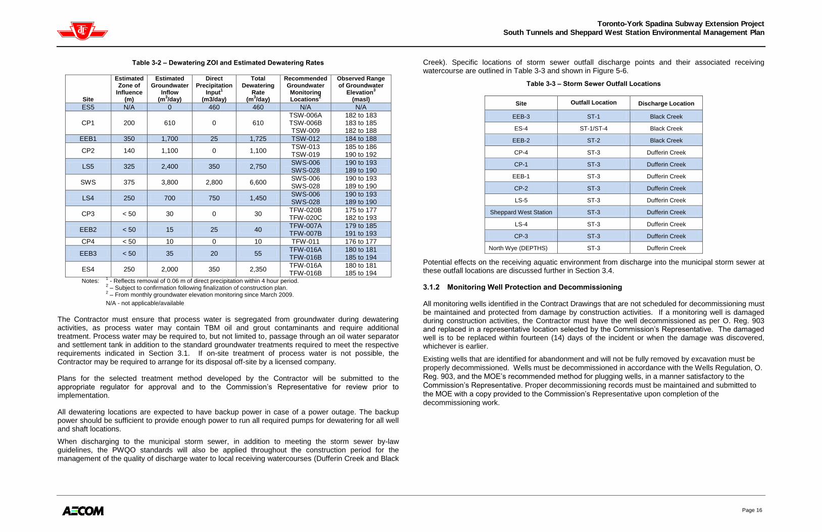
The groundwater dewatering Zones of Influence (ZOI) will be monitored throughout the construction period and during the post-construction recovery period. Temporary (and localized) water table drawdown will be monitored in available monitoring wells in the vicinity of proposed excavations (i.e. where construction dewatering is to occur). Figure 3-2 indicates the ZOI for the full alignment of the TYSSE including the South Tunnels and Sheppard West Station. Table 3-2 summarizes the estimated ZOI, estimated groundwater inflow, direct precipitation inflow, and total dewatering rate for the South Tunnels and Sheppard West Station Sites prepared by Golder (Predicted Dewatering Rates and Zone of Influence for Excavation Locations – Toronto-York Spadina Subway Extension – Draft Technical Memorandum, March 3, 2010). The direct precipitation input is based upon a five (5) year return period storm event for a 24-hour rain event duration.

Toronto-York Spadina Subway Extension Project
South Tunnels and Sheppard West Station Environmental Management Plan
Page 15
Figure 3-1 – Zone of Influence Map
Toronto-York Spadina Subway Extension Project
South Tunnels and Sheppard West Station Environmental Management Plan
Page 16
Table 3-2 – Dewatering ZOI and Estimated Dewatering Rates
Site
Estimated Zone of
Influence
(m)
Estimated Groundwater
Inflow (m
3/day)
Direct Precipitation
Input1
(m3/day)
Total Dewatering
Rate (m
3/day)
Recommended Groundwater Monitoring Locations
2
Observed Range of Groundwater
Elevation3
(masl)
ES5 N/A 0 460 460 N/A N/A
CP1 200 610 0 610 TSW-006A TSW-006B TSW-009
182 to 183 183 to 185 182 to 188
EEB1 350 1,700 25 1,725 TSW-012 184 to 188
CP2 140 1,100 0 1,100 TSW-013 TSW-019
185 to 186 190 to 192
LS5 325 2,400 350 2,750 SWS-006 SWS-028
190 to 193 189 to 190
SWS 375 3,800 2,800 6,600 SWS-006 SWS-028
190 to 193 189 to 190
LS4 250 700 750 1,450 SWS-006 SWS-028
190 to 193 189 to 190
CP3 < 50 30 0 30 TFW-020B TFW-020C
175 to 177 182 to 193
EEB2 < 50 15 25 40 TFW-007A TFW-007B
179 to 185 191 to 193
CP4 < 50 10 0 10 TFW-011 176 to 177
EEB3 < 50 35 20 55 TFW-016A TFW-016B
180 to 181 185 to 194
ES4 250 2,000 350 2,350 TFW-016A TFW-016B
180 to 181 185 to 194
Notes: 1 - Reflects removal of 0.06 m of direct precipitation within 4 hour period.
2 – Subject to confirmation following finalization of construction plan.
2 – From monthly groundwater elevation monitoring since March 2009.
N/A - not applicable/available
The Contractor must ensure that process water is segregated from groundwater during dewatering activities, as process water may contain TBM oil and grout contaminants and require additional treatment. Process water may be required to, but not limited to, passage through an oil water separator and settlement tank in addition to the standard groundwater treatments required to meet the respective requirements indicated in Section 3.1. If on-site treatment of process water is not possible, the Contractor may be required to arrange for its disposal off-site by a licensed company.
Plans for the selected treatment method developed by the Contractor will be submitted to the appropriate regulator for approval and to the Commission‟s Representative for review prior to implementation.
All dewatering locations are expected to have backup power in case of a power outage. The backup power should be sufficient to provide enough power to run all required pumps for dewatering for all well and shaft locations.
When discharging to the municipal storm sewer, in addition to meeting the storm sewer by-law guidelines, the PWQO standards will also be applied throughout the construction period for the management of the quality of discharge water to local receiving watercourses (Dufferin Creek and Black
Creek). Specific locations of storm sewer outfall discharge points and their associated receiving watercourse are outlined in Table 3-3 and shown in Figure 5-6.
Table 3-3 – Storm Sewer Outfall Locations
Site Outfall Location Discharge Location
EEB-3 ST-1 Black Creek
ES-4 ST-1/ST-4 Black Creek
EEB-2 ST-2 Black Creek
CP-4 ST-3 Dufferin Creek
CP-1 ST-3 Dufferin Creek
EEB-1 ST-3 Dufferin Creek
CP-2 ST-3 Dufferin Creek
LS-5 ST-3 Dufferin Creek
Sheppard West Station ST-3 Dufferin Creek
LS-4 ST-3 Dufferin Creek
CP-3 ST-3 Dufferin Creek
North Wye (DEPTHS) ST-3 Dufferin Creek
Potential effects on the receiving aquatic environment from discharge into the municipal storm sewer at these outfall locations are discussed further in Section 3.4.
3.1.2 Monitoring Well Protection and Decommissioning
All monitoring wells identified in the Contract Drawings that are not scheduled for decommissioning must be maintained and protected from damage by construction activities. If a monitoring well is damaged during construction activities, the Contractor must have the well decommissioned as per O. Reg. 903 and replaced in a representative location selected by the Commission‟s Representative. The damaged well is to be replaced within fourteen (14) days of the incident or when the damage was discovered, whichever is earlier.
Existing wells that are identified for abandonment and will not be fully removed by excavation must be
properly decommissioned. Wells must be decommissioned in accordance with the Wells Regulation, O.
Reg. 903, and the MOE‟s recommended method for plugging wells, in a manner satisfactory to the
Commission‟s Representative. Proper decommissioning records must be maintained and submitted to
the MOE with a copy provided to the Commission‟s Representative upon completion of the
decommissioning work.

Toronto-York Spadina Subway Extension Project
South Tunnels and Sheppard West Station Environmental Management Plan
Page 17
3.2 EROSION AND SEDIMENT CONTROL
In order to minimize the off-site transport of construction sediments and prevent erosion within the
receiving surface drainage system, comprehensive siltation and erosion control plans will be established
for each construction site. Erosion and Sediment Control (ESC) measures on all construction sites will
be designed as per the Erosion and Sediment Control Guideline for Urban Construction, December
2006 (ESC Guideline), prepared by the Greater Golden Horseshoe Area Conservation Authorities
(GGHACA). Specific regulations and recommendations will be considered based on site location (City
of Toronto) and site-specific natural features and ecologically sensitive receptors.
The guiding principles of the GGHACA‟s ESC Guideline focus on mitigating the large scale impacts urban development can have on the natural environment using a multi-barrier approach with a dynamic ESC plans, including improved inspection.
ESC Planning entails the following principles:
Multi-barrier approach;
Retain existing vegetation and stabilize ground with vegetation where possible;
Limit duration of soil exposure and/or phase construction;
Limit size of disturbed area;
Maintain overland sheet flow and avoid concentrating flow;
Store and stockpile soil away from watercourses, drainage structures, and the top of slopes;
ESC training for Contractors and construction management;
Prepare an adaptive ESC plan; and,
Assess ESC measure before and after rain and significant snowmelt events.
Preparation of the construction sites will entail the hardening of the ground surface to provide a stable base for construction activities. This change will affect both the quantity and quality of runoff. The added construction sediment from each site‟s runoff has the potential to have negative effects on the local aquatic resources. The goal of the ESC measures is to preserve and protect the aquatic resources and other natural features of identified environmentally-sensitive sites affected by the construction for the TYSSE Project. On all sites, multiple layers of protection are to be employed along with a regulated process for monitoring and maintenance to ensure that the measures are functioning within approved limits. ESC condition reports will be prepared as part of the monitoring and maintenance plan. Where ESC measures are found to be in an unacceptable condition they are to be repaired or replaced immediately.
Erosion and sediment control measures include:
Erosion prevention measures (seeding, mulch, vegetative cover).
Sediment controls: perimeter (silt fence), settling (excavated sediment traps), and filtration (catch basin inserts).
ESC measures for the TYSSE construction sites may include, but are not limited to:
Heavy Duty Silt Fence: Woven Geotextile, installed as per OPSD 219.130.
Jersey Barrier with Silt Fence: Non-woven Geotextile placed against the site perimeter jersey barriers and weighted with sandbags to provide perimeter control on paved surfaces.
Staked Sediment Control Logs: Continuous knitted mesh netting filled with compost filter media. Control log to be staked to ground and used in place of heavy duty silt fence for perimeter control or rock flow check dam in ditches.
Truck Wash: Automated truck wheel washing system to spray construction vehicles prior to exiting site to reduce mud and debris tracking onto adjacent streets. Systems should including water recycle, sediment management, and a winter heating package. Installed as per manufacturer‟s recommendations.
Mud Mat: Pad constructed of clear stone underlain with geotextile at the site access points to remove mud and debris from vehicles prior to exiting the site. Installed as per GGHACA‟s ESC Guideline (Appendix C – Vehicle Tracking Control/Mud Mats).
Concrete Wash-out Station: Single, stackable or multiple rings of continuous knitted mesh netting filled with compost filter media, for containing concrete washout water.
Storm Drain Inlet Protection: Sediment control barrier consisting of either a filter fabric around a catch basin inlet with crushed stone over the grate or manufactured geotextile sack inserted inside the catch basin.
Sediment Traps: Depression area which allows runoff to pond, which permits coarser particles to settle out. Installed as per OPSD 219.220.
Temporary Rock Check Flow Dams: Installed as per OPSD 219.210 and OPSD 219.211.
Sediment Control Ponds: Designed and installed as per the MOE Surface Water Management (SWM) Planning and Design Manual, 2003.
Erosion Control Blankets: Installed as per GGHACA‟s ESC Guideline (Appendix C – Erosion Control Blankets, Mats, Nets) to exposed slopes greater than 2H:1V.
Mulch: Partially composted chipped woody material placed on exposed soils.
Hydroseed: Applied as per manufacturer‟s recommendations and GGHACA‟s ESC Guideline (Appendix C - Hydroseeding).
As part of the ESC design process, ESC Reports, including ESC, construction storm water management, and grading plans, will be produced for each construction site on the alignment detailing the surrounding area, adjacent sensitive features and critical areas, soil conditions, condition of existing receiving water, and the proposed ESC measures such as material used, ESC pond, and stockpile details. Ultimately, the Contractor in charge of each construction site is responsible for ensuring the layout of the site, with approval from responsible parties. Where changes in construction staging and arrangement of Construction Sites occurs that are not anticipated by the ESC plans a revised ESC plan must be prepared by the Contractor. The revised plan must show the modification to the ESC plans to account the changes in construction staging and Construction Site arrangement. These revised ESC plans must be submitted for review by the Commission‟s Representation prior to implementation of the construction staging and/or arrangement of the Construction Sites.
3.3 SURFACE WATER RUNOFF MANAGEMENT
Surface water runoff management requires the implementation of mitigation measures by the Contractor(s) during construction to ensure the following:
Protection of local vegetation from flooding and/or soil saturation (frequent or prolonged inundation of soil);
Proper site drainage is maintained in order to provide a dry and safe work environment; and,
Protection of excavations and trenches against flooding and damage.
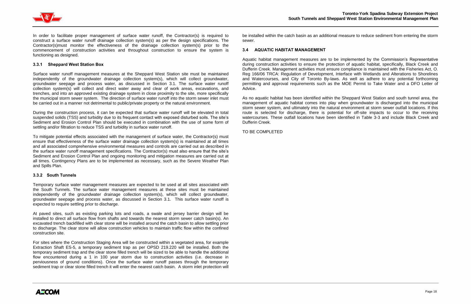
Toronto-York Spadina Subway Extension Project
South Tunnels and Sheppard West Station Environmental Management Plan
Page 18
In order to facilitate proper management of surface water runoff, the Contractor(s) is required to construct a surface water runoff drainage collection system(s) as per the design specifications. The Contractor(s)must monitor the effectiveness of the drainage collection system(s) prior to the commencement of construction activities and throughout construction to ensure the system is functioning as designed.
3.3.1 Sheppard West Station Box
Surface water runoff management measures at the Sheppard West Station site must be maintained independently of the groundwater drainage collection system(s), which will collect groundwater, groundwater seepage and process water, as discussed in Section 3.1. The surface water runoff collection system(s) will collect and direct water away and clear of work areas, excavations, and trenches, and into an approved existing drainage system in close proximity to the site, more specifically the municipal storm sewer system. The direction of surface water runoff into the storm sewer inlet must be carried out in a manner not detrimental to public/private property or the natural environment.
During the construction process, it can be expected that surface water runoff will be elevated in total suspended solids (TSS) and turbidity due to its frequent contact with exposed disturbed soils. The site‟s Sediment and Erosion Control Plan should be executed in combination with the use of some form of settling and/or filtration to reduce TSS and turbidity in surface water runoff.
To mitigate potential effects associated with the management of surface water, the Contractor(s) must ensure that effectiveness of the surface water drainage collection system(s) is maintained at all times and all associated comprehensive environmental measures and controls are carried out as described in the surface water runoff management specifications. The Contractor(s) must also ensure that the site‟s Sediment and Erosion Control Plan and ongoing monitoring and mitigation measures are carried out at all times. Contingency Plans are to be implemented as necessary, such as the Severe Weather Plan and Spills Plan.
3.3.2 South Tunnels
Temporary surface water management measures are expected to be used at all sites associated with the South Tunnels. The surface water management measures at these sites must be maintained independently of the groundwater drainage collection system(s), which will collect groundwater, groundwater seepage and process water, as discussed in Section 3.1. This surface water runoff is expected to require settling prior to discharge.
At paved sites, such as existing parking lots and roads, a swale and jersey barrier design will be installed to direct all surface flow from shafts and towards the nearest storm sewer catch basin(s). An excavated trench backfilled with clear stone will be installed around the catch basin to allow settling prior to discharge. The clear stone will allow construction vehicles to maintain traffic flow within the confined construction site.
For sites where the Construction Staging Area will be constructed within a vegetated area, for example Extraction Shaft ES-5, a temporary sediment trap as per OPSD 219.220 will be installed. Both the temporary sediment trap and the clear stone filled trench will be sized to be able to handle the additional flow encountered during a 1 in 100 year storm due to construction activities (i.e. decrease in perviousness of ground conditions). Once the surface water runoff passes through the temporary sediment trap or clear stone filled trench it will enter the nearest catch basin. A storm inlet protection will
be installed within the catch basin as an additional measure to reduce sediment from entering the storm sewer.
3.4 AQUATIC HABITAT MANAGEMENT
Aquatic habitat management measures are to be implemented by the Commission‟s Representative during construction activities to ensure the protection of aquatic habitat, specifically, Black Creek and Dufferin Creek. Management activities must ensure compliance is maintained with the Fisheries Act, O. Reg 166/06 TRCA: Regulation of Development, Interface with Wetlands and Alterations to Shorelines and Watercourses, and City of Toronto By-laws. As well as adhere to any potential forthcoming permitting and approval requirements such as the MOE Permit to Take Water and a DFO Letter of Advice.
As no aquatic habitat has been identified within the Sheppard West Station and south tunnel area, the management of aquatic habitat comes into play when groundwater is discharged into the municipal storm sewer system, and ultimately into the natural environment at storm sewer outfall locations. If this route is selected for discharge, there is potential for off-site impacts to occur to the receiving watercourses. These outfall locations have been identified in Table 3-3 and include Black Creek and Dufferin Creek.
TO BE COMPLETED

Toronto-York Spadina Subway Extension Project
South Tunnels and Sheppard West Station Environmental Management Plan
Page 19
Table 3-4 – Summary of Thermal and Erosion Assessment
TO BE COMPLETED
Discharge Point (Outfall Location)
Receiving Watercourse
Proposed Discharge Rate
(L/sec) DRY
Proposed Discharge Rate
(L/sec) WET
Estimated Existing Baseflow
(L/sec)
Erosion Threshold
(L/s)
Estimated Max. Temp. of Receiving
Watercourse (°C)
Estimated Temperature of Groundwater
Discharge (°C)
Estimated Max. Thermal Influence
on Receiving Watercourse (°C)
ST-1 (Option 1)
Black Creek
ST-1 (Option 2)
Black Creek
ST-1 (Option 3)
Black Creek
ST-2 Black Creek
ST-3 Dufferin Creek
ST-4 (Option 1)
Black Creek
ST-4 (Option 3)
Black Creek

Toronto-York Spadina Subway Extension Project
South Tunnels and Sheppard West Station Environmental Management Plan
Page 20
3.4.1 Water Quality
Impacted surface water from a spill or water not meeting the target objectives that is released or discharged into the storm sewer system, and ultimately the natural environment, may cause immediate to long term impacts on water quality of the receiving watercourses (Black Creek & Dufferin Creek). These impacts on water quality have potential to result in an alteration in the aquatic community from physiological stress to death. To mitigate potential effects associated with the release or discharge, the Contractor(s) must first immediately stop the release or discharge of the impacted water into the storm sewer and refrain from discharging until water quality is proven acceptable to municipal storm sewer guidelines and PWQO criteria. Ongoing compliance with the established groundwater and storm water collection drainage plan(s), groundwater monitoring plan as outlined in section 4.1, sediment and erosion control plans, as well as Contingency Plans (i.e. Spills) is required to mitigate potential impacts related to water quality.
3.4.2 Thermal Changes
TO BE COMPLETED
3.4.3 Stream Erosion (sedimentation)
TO BE COMPLETED
3.5 VEGETATION PROTECTION
Detailed plant and tree inventories were conducted at the Sheppard West Station area and along the South Tunnel alignment at the construction sites. The vegetation communities were documented according to the Ecological Land Classification (ELC) System for Southern Ontario1.
The following are the locations where the vegetation surveys were conducted for the South Tunnel:
Downsview Station Connection to Wilson Yard, Parc Downsview Park, west side of Allen Road, south of Sheppard Avenue;
Extraction Shaft #5 (ES-5), berm between Dufferin Street and Allen Road, just north of Sheppard Avenue and west of Allen Road;
EEB-1, north side of Kodiac Crescent and Whitehorse Road;
Cross Passage #2 (CP-2), Sheppard West Station, and Track Laydown Area, Parc Downsview Park, south side of Sheppard Avenue West, east of the GO tracks;
Sheppard West Station, Parc Downsview Park, south side of Sheppard Avenue at the GO tracks
CP-3 area, west side of Tuscan Gate, north of Sheppard Avenue;
EEB-2, north side of St. Regis Crescent, east of Keele Street; and,
EEB-3, intersection of Keele Street and Toro Road.
1 Lee, H. T., W.D. Bakowsky, J. Riley, J. Bowles, M. Puddister, P. Uhlig and S. McMurray. 1998.
Ecological Land Classification for Southern Ontario: First Approximation and Its Application.
Ontario Ministry of Natural Resources, Southcentral Science Section, Science Development
and Transfer Branch. SCSS Field Guide FG-02.
Trees were mapped and inventoried by species, size (DBH) and health. Tree Protection & Preservation Plans were prepared for each construction area. The plans also include recommendations for measures that will protect the long-term tree health.
Tree protection is in accordance with City of Toronto Municipal Code 813 – Trees, which includes Article II (City Owned Trees) and Article III (Private Trees). Tree protection zones, as per the City of Toronto Tree Protection Policy and Specification for Construction Near Trees (March 2009), will be identified as required on the corresponding construction site plans.
3.5.1 Tree Protection Zones
All trees that are to be retained within or adjacent to the South Tunnel construction zones and Sheppard West Station will require tree protection zones (TPZs).

Toronto-York Spadina Subway Extension Project
South Tunnels and Sheppard West Station Environmental Management Plan
Page 21
Table 3-5 provides the minimum tree protection distances required for TPZs as per the City of Toronto Tree Protection Policy. It may be necessary to implement other protective measures in addition to establishing TPZs to properly ensure tree health. These additional measures may include: adding mulch to the root zone, aeration of the soil, pruning for deadwood, and removing limbs that may be impacted by construction activities. Additional measures will be implemented at the direction of a certified arborist.
Within areas designated as TPZs, the following guidelines specified by the Tree Protection Policy, need to be adhered to:
No construction activities;
No altering of grade by adding fill, excavating, trenching, scraping, dumping, or disturbance of any kind;
No storage of construction materials, equipment, soil, construction waste, or debris;
No disposal of any liquids (e.g. concrete wash-out, gas, oil, etc.);
No movement of vehicles or machinery;
Directional micro tunnelling and boring may be permitted within the limits of a TPZ subject to proper approval; and,
An exploratory dig, either by hand or using low water pressure hydro vac method, must be completed prior to commencing with open face cuts outside the TPZ that require root pruning performed by a certified arborist or approved tree professional.
Table 3-5 – Tree Protection Zones for City-owned and Private Trees
Trunk Diameter (DBH) Minimum Protection Distances Required1
< 10 cm 1.2 m
10-29 cm 1.8 m
302-40 cm 2.4 m
41-50 cm 3.0 m
51-60 cm 3.6 m
61-70 cm 4.2 m
71-80 cm 4.8 m
81-90 cm 5.4 m
91-100 cm 6.0 m
> 100 cm 6 cm protection for each 1 cm diameter
1 Tree Protection Zone distances are to be measured from the outside edge of the tree base.
2 Diameter (30 cm) at which trees qualify for protection under the City of Toronto private tree by-law.
TPZs will be delineated using tree protection barriers that are to be constructed of plywood or plastic web hoarding or equivalent as approved by a certified arborist. Support and bracing are to be outside the TPZ and should minimize root damage outside the TPZ. Where the roots of a protected tree need to be protected outside of a TPZ, root protection consisting of a combination of filter fabric, clear crushed stone placed in a 15 cm deep layer, and steel plating or equivalent, shall be installed as instructed by a certified arborist.
In addition to the establishment of Tree Protection Zones (TPZ), the following specifications are recommended:
1. Before beginning work, the Contractor and the certified arborist should meet on-site to review work procedures, access routes, storage areas and the TPZ or other tree protection measures.
2. Any underground utilities shall be routed outside the TPZ, or use tunnelling or boring methods for installation.
3. Any root damage occurring during construction should be cut cleanly to the sound tissue. 4. Any injury to a tree during construction should be evaluated by a certified arborist. 5. Any pruning of trees for construction clearance shall be performed by a certified arborist.
3.5.2 Tree Removal
Where trees are to be removed, proper approval must first be obtained from the appropriate authority. Removal, cost, and replacement arrangements will be made with the governing authority. A permit is required from the City of Toronto‟s General Manager Parks, Forestry and Recreation for all city-owned trees prior to injuring, destroying or removal. For trees on private property, a permit is required prior to injuring, destroying or removing any tree that is 30 cm DBH or greater.

Toronto-York Spadina Subway Extension Project
South Tunnels and Sheppard West Station Environmental Management Plan
Page 22
All trees in the South Tunnel Contract area are within the Canadian Food Inspection Agency (CFIA) Regulated Area for Asian Long Horned Beetle (ALHB) and Emerald Ash Borer (EAB). Do not move wood debris from trees of the following species out of the Regulated Area for ALHB (Dufferin west to Hwy 27 and Rutherford Road south to Hwy 401 & 409).
Acer sp. (Maple)
Aesculus sp. (Horse Chestnut)
Salix sp. (Willow)
Ulmus sp. (Elm)
Betula sp . (Birch)
Platanus sp. (Sycamore - London Plane Tree)
Celtis sp. (Hackberry)
Populus sp. (Poplar)
Sorbus sp. (Mountain Ash)
Albizia sp. (Silk Tree)
All Ash sp. (Fraxinus) are host trees for EAB.
The Contractor shall take all woody debris from the above species to the regulated disposal yard this includes wood, logs, wood chips, branches, brush and leaves.
Regulated Disposal Yard:
Dufferin Transfer Station: 35 Vanley Crescent (south of Finch off Chesswood Drive), North York 416-392-3161 Monday - Friday 6am-6pm Saturday and Sunday – Closed
3.5.3 Trimming/Pruning/Root Cutting
Following the City of Toronto‟s Tree Protection Policy:
Any roots or branches which extend beyond the TPZ indicated on this plan which require pruning, must be pruned by a certified arborist or other tree professional as approved by Urban Forestry. All pruning of tree roots and branches must be in accordance with good arboricultural standards. Roots located outside the TPZ that have received approval from Urban Forestry to be pruned must first be exposed by hand digging or by using a low pressure hydro vac method. This will allow a proper pruning cut and minimize tearing of the roots. The certified arborist/tree professional retained to carry out crown or root pruning must contact Urban Forestry no less than 48 hours prior to conducting any specified work.
3.6 WILDLIFE PROTECTION
3.6.1 Breeding Birds
Clearing and construction activities for the TYSSE must be done in compliance with the federal Migratory Birds Convention Act. The Act is applied through The Regulations Respecting the Protection of Migratory Birds that states that “[…] no person shall disturb, destroy or take a nest, egg […] of a migratory bird.” This law protects all birds aside from the introduced species European Starling, House Sparrow, and Rock Pigeon. Bird nests that are destroyed during the course of construction and other related activities is referred to as “incidental take” and is illegal except under the authority of a permit obtained through the CWS (Canadian Wildlife Service).
During construction staging planning, vegetation clearing or tree cutting should be scheduled outside of the breeding bird period, spring and early summer. It is preferential for construction activities to begin prior to the breeding bird period so that birds arriving to nest in the area will naturally avoid the construction area and establish alternative breeding territories.
If clearing and other construction activities can be planned outside of the breeding bird period, the risk of disturbing nests and eggs is greatly reduced. If disruptive activities must occur during the breeding bird period, a detailed nest survey must be undertaken by a qualified biologist. Areas with active nests cannot be disturbed until the young have fledged. Where no active nests are found, disruptive activities may occur only within three (3) days of the survey. The survey must be repeated if the work is to take longer than three (3) days.
All cleared vegetation must be removed immediately from site as birds may nest in the piles and prevent their removal until after the young have fledged.
If nests are discovered they must be protected by providing an area of no disturbance around the nest until the young have fledged. As the zone of no disturbance is species dependent, contact the avian biologist to identify the species and assess the no disturbance zone required.

Toronto-York Spadina Subway Extension Project
South Tunnels and Sheppard West Station Environmental Management Plan
Page 23
4. MONITORING AND ADAPTIVE MANAGEMENT PLANS
Monitoring of the construction activities allows for assessment of predicted effects on the surrounding environment and key receptors with the collection of data and documentation of observations. While the proactive measures detailed in Section 3 provide the first line of defence, by monitoring, it can be assumed that the ultimate protection levels are maintained. All parameters summarized in Table 4-1 shall be monitored.
Monitoring plans will be carried out with reference to baseline, trigger, and alarm values (levels) these reference points are described below and are applied to monitoring activities outlined in Table 1-1; monitoring periods are defined in Section 1.6.3, Monitoring Responsibilities.
Baseline levels represent the monitoring levels that must be consistently met to ensure that no environmental impacts are sustained during the Project undertaking. Baseline levels were developed based on the legislative monitoring requirements dictated in Project-specific agreements, municipal by-laws, and supportive guidelines established by applicable organizations.
Trigger levels are above the baseline level and are typically, but not always set by governing bodies or accepted standards (i.e. the level required by agreements, legislation and guidelines); however, if promptly addressed, short-term conditions at the trigger level should not cause environmental impact. If trigger levels are reached, the Contractor must investigate the cause of the exceedance above the baseline values and implement appropriate action plan and appropriate adaptive management measures. During the investigation, increased monitoring shall be implemented so that exceedance values can be closely tracked. If the Contractor‟s EIL submissions indicate ongoing monitoring results at the trigger level (i.e. above the baseline), the Commission‟s Representative shall investigate and require the Contractor(s) to implement an adaptive management program.
If the alarm level is reached, the Contractor(s) must notify the Commission‟s Representative immediately. The appropriate action plan, adaptive management program, and contingency plan must be implemented immediately, and a long-term solution developed. If the cause of the alarm level is continuous or if it has potential to reoccur, the Commission‟s Representative may require the suspension of activities contributing to the exceedance until appropriate safeguards have been put in place by the Contractor.
Monitoring action pathways have been developed for implementation when a baseline, trigger or alarm value is met are provided for each appropriate monitoring component

Toronto-York Spadina Subway Extension Project
South Tunnels and Sheppard West Station Environmental Management Plan
Page 24
Table 4-1 – Monitoring Plan and Associated Baseline, Trigger and Alarm Values
Parameter Location Standard Responsibility Frequency Baseline Trigger Alarm
Groundwater
Dewatering
Discharge Quality
Discharge point from water
treatment or groundwater
sump to municipal sewer
(storm or sanitary)
City of Toronto Municipal
Code (all parameters)
and PWQO
Contractor(s)- EM
1x day for the first week of pumping prior to discharge
2x week (every three (3) or four (4) days) for the next three (3) weeks
1x month thereafter
As required by relevant authorities, if greater than specified above.
Meets applicable standards for
all parameters
At applicable City of Toronto
Sewer Use By-law and PWQO
standards or one sampling event
with parameters above the
applicable standard
Above applicable City of Toronto
Sewer Use By-law and PWQO
standards when re-sampled after
initial exceedance
Groundwater
Dewatering
Discharge Filter(s)
(if required)
Discharge of groundwater
sump, before entering storm
sewer
Filter manufacturing
guidance manual Contractor(s)- EM
2x day visual check
Replace as necessary
Filtration systems are functioning
and filters are below 80% of their
maximum capacity according to
the accompanying guidance
manual
Filtration systems are functioning
and filters are between 80% and
95% of their maximum capacity
according to the accompanying
guidance manual
Filtration are not functioning and
filters have reached their
maximum capacity according to
the accompanying guidance
manual
Surface Water
Runoff
Management
Surface water drainage
collection system(s),Sheppard
West Station Site and tunnel
construction locations
Proper site drainage is
maintained and the
surface water drainage
collection system(s) is in
good function
Contractor(s)- EM
Frequent daily observations
Prior to, during and post forecasted
20mm/24hour rain event or thaw event
No evidence of spills, no on-site
flooding
Observed areas of pooled
surface water or saturated soils
Spill or deleterious substance is
present within surface water
runoff, observed on-site flooding
Surface Water
Temperature
Discharge point to municipal
sewer (storm or sanitary) TBC TBC
TBC TBC TBC TBC
Stream Erosion Black Creek and Dufferin
Creek, at storm sewer outfalls
Baseline conditions prior
to groundwater discharge
to storm sewer
Commission‟s
Representative-
Fluvial
Geomorphologist
TBC
TBC TBC TBC
Groundwater
Level Shafts and Station Box Dewatering Specification
Commission‟s
Representative
1x weekly
1x monthly (recovery period) for 1 year
period or 85% recovery
0.7-1.2 m below the invert of the
shafts
600 mm below excavation floor
0.6 m -0.7 m below the invert of
the shafts
500 mm below excavation floor
<0. 6 m below the invert of the
shafts
<500 mm below excavation floor
Terrestrial Health Station Site, tunnel
construction locations Visual Survey
Contractor(s) –
Arborist and/or
Terrestrial Ecologist
2x annually during the growing season
to inspect TPZ and tree conditions
Periodically outside the growing
season for the duration of dewatering
and recovery to inspect TPZ and tree
conditions
EM does not identify any
concerns with respect to tree or
vegetation health
EM identifies first signs of drought
stress (wilting of foliage) in trees
and vegetation
EM identifies drought stress
(drying of foliage, premature leaf
fall and desiccation in herbaceous
plants) in trees and vegetation
Erosion and
Sediment Controls Throughout Project site EMP Protocols Contractor(s)- EM
1x weekly
After large rainfall events (>20mm in
24 hours)
After significant snowmelt events
1x daily during extended rain or
snowmelt periods
1x monthly during inactive construction
periods, where the site is left alone for
thirty (30) days or longer
Erosion and sediment controls
are functioning properly and are
within the trigger levels outlined
in Table 4-3.
Erosion and sediment controls at
the trigger levels outlined in Table
4-3.
Erosion and sediment controls are
at the action levels outlined in
Table 4-3.

Toronto-York Spadina Subway Extension Project
South Tunnels and Sheppard West Station Environmental Management Plan
Page 25
4.1 GROUNDWATER MONITORING
Given the cost considerations for discharging to sanitary, groundwater discharges will be principally directed to the storm sewer. However, the Contractor must have the appropriate permits to discharge to both the storm and sanitary sewer system, as required. Diversion of pumped groundwater to municipal sewers must be recorded daily, either on an EIL or another agreed-upon form. The Contractor is responsible for ensuring that discharges from the water treatment system are tested against the water quality parameters defined in the City of Toronto Municipal Code – Sewers (Chapter 681), and PWQO guidelines (if discharging to storm sewer) as follows:
Once a day for the first week of pumping prior to discharge (water is collected and contained until results from first two (2) days are received) at the commencement of dewatering;
Twice a week (every three (3) or four (4) days) for the next three (3) weeks (water may be discharged prior to receipt analytical results);
Once a month thereafter (water may be discharged prior to receipt analytical results); and,
As required by relevant authorities, if greater than specified above.
The above testing cycle must be initiated by the Contractor as soon as groundwater discharge is diverted to the storm sewer and must be completed separately at each construction site where different source water is discharged, including: station box (launch shafts), EEBs, extraction shafts and cross-passages, as required. All new source waters shall be analyzed at the discharge point as per the schedule outlined above.
For sanitary discharge, the Contractor may monitor groundwater quality prior to treatment to confirm whether groundwater meets sanitary sewer requirements without treatment. If the Contractor has completed monthly sampling that demonstrates that the groundwater consistently meets sanitary sewer discharge limits2, then the Contractor may discharge untreated groundwater directly to sanitary between monthly monitoring events, if the situation should arise that water cannot be discharged to storm sewer (i.e. permit may include storm discharge limitations during rain events or if temporary dewatering requirements exceed permitted discharge quantities to storm). If groundwater does not consistently meet sanitary sewer discharge limits, the Contractor will be required to treat the groundwater prior to discharge according to the protocols outlined for storm sewer discharges.
The Contractor shall submit laboratory results to the Commission‟s Representative within 24-hours of receipt. Laboratory results may be appended to the EILs and Weekly Summary Report.
The action plan presented in Figure 4-1 shall be followed regarding any discharge of groundwater to the municipal sanitary sewer system. Please note that all required permits must be obtained from the respective municipality prior to discharge to the municipal sanitary sewer system.
2 Groundwater meets the sanitary sewer by-law requirements for all parameters in four out of every five sampling
events (80%). The exemption shall only be allowed if there were no order of magnitude exceedances of any
parameters in any of the five sampling events.
Figure 4-1 – Discharge Water Action Plan – Municipal Sanitary and Storm Sewer
4.1.1 Water Table Drawdown
Temporary water table drawdown will be monitored at designated monitoring wells throughout the construction period and post-construction. These results will be incorporated into the broader environmental monitoring (i.e. monitoring of terrestrial resources locally). Table 4-2 provides a summary of the groundwater level monitoring frequencies, potential monitoring locations for each site, and the observed range of groundwater elevations for each monitoring location. More frequent monitoring may be required during start up of dewatering systems to assess predicted dewatering rates and effects.

Toronto-York Spadina Subway Extension Project
South Tunnels and Sheppard West Station Environmental Management Plan
Page 26
Table 4-2 – Dewatering Monitoring Details
Site
Estimated Zone of
Influence
(m)
Groundwater Level Monitoring Frequency
Recommended
Groundwater
Monitoring
Locations1
Observed Range of
Groundwater Elevation
2
(masl)
During Construction
Post Construction
ES5
Weekly
Monthly for 1 year
period or 85%
recovery to observed range of
groundwater elevation
N/A
CP1 200 TSW-006A TSW-006B TSW-009
182 to 183 183 to 185 182 to 188
EEB1 350 TSW-012 184 to 188
CP2 140 TSW-013 TSW-019
185 to 186 190 to 192
LS5 325 SWS-006 SWS-028
190 to 193 189 to 190
SWS 375 SWS-006 SWS-028
190 to 193 189 to 190
LS4 250 SWS-006 SWS-028
190 to 193 189 to 190
CP3 < 50 TFW-020B TFW-020C
175 to 177 182 to 193
EEB2 < 50 TFW-007A TFW-007B
179 to 185 191 to 193
CP4 < 50 TFW-011 176 to 177
EEB3 < 50 TFW-016A TFW-016B
180 to 181 185 to 194
ES4 250 TFW-016A TFW-016B
180 to 181 185 to 194
North Wye (DEPTHS)
80 TYU-003 190 to 194
1 – Subject to confirmation following finalization of construction plan.
2 – From monthly groundwater elevation monitoring since March 2009.
The dewatering action plan presented in Figure 3-3 shall be followed to ensure proper groundwater levels are maintained within excavations for dewatering operations.
Figure 4-2 – Area of Influence Dewatering Action Plan

Toronto-York Spadina Subway Extension Project
South Tunnels and Sheppard West Station Environmental Management Plan
Page 27
4.2 EROSION AND SEDIMENT CONTROL
The monitoring protocols for erosion and sediment control measures will follow the GGHACA‟s ESC Guideline for Inspections and Performance Monitoring (Section 7.0).
A monitoring and inspection program shall be developed by the Contractor for each construction site prior to the commencement of construction activities. As stated in the GGHACA‟s ESC Guideline, this program should include:
1. Identification of Personnel: Names and contact information of Project members assigned to each task as well as agency/enforcement contacts. A communication protocol should also be developed to ensure effective reporting and compliance.
2. Details and locations of the environmental constraints for an undertaking (the project area or site) including maps, reports, approvals and permits. Specific attention should be directed to timing restrictions and reporting requirements.
3. Construction drawings detailing the erosion and sediment controls installed which are updated through the construction period.
4. High risk areas should be identified on these drawings and routinely evaluated. Greater frequency of monitoring requirements may be required for areas and protection measures immediately adjacent to soil stockpiles, excavations, dewatering locations, protected features/areas, and locations where site runoff discharges into a receiving watercourse, water body, or municipal sewer system.
5. Inspection schedule: This should include inspection times, areas, and person(s) responsible for the inspections. A „walk-through‟ inspection of the construction site should be undertaken in anticipation of large storm events (or a series of rainfall and/or snowmelt days) that could potentially yield significant runoff volumes. The regular inspections should occur during all construction stages and should be based on at a minimum the requirement identified in the permits and approvals. Commonly this frequency is:
On a weekly basis;
After large rainfall events (>20 mm in 24 hours);
After significant snowmelt events; and
Daily during extended rain or snowmelt periods.
During inactive construction periods, where the site is left alone for thirty (30) days or longer, a monthly inspection should be conducted.
6. All damaged erosion and sediment control measures should be repaired and/or replaced within 48 hours of the inspection.
Post-construction monitoring may be required to certify that proper restoration, stabilization, and overall quality of runoff is returned to pre-construction conditions.
The construction monitoring plan should also include provisions for monitoring and maintenance to ensure the ESC measures at each site are functioning within their established discharge quality and quantity limits.
As noted in Section 4, Table 4-1 shows the components of the monitoring program and the actions to be taken for each Erosion and Sediment Control (ESC) measure should the trigger or alarm level be reached. Ideally, with adequate monitoring, the ESC measures should be maintained daily or in a timely fashion such that trigger levels are not reached.
Figure 4-3 presents the action plan that shall be followed to ensure that the ESC measures are maintained and functioning as intended.
Table 4-3 – Monitoring for Erosion and Sediment Control Measures
Measure Monitoring / Trigger Level Action Level
Heavy Duty Silt Fence 30% full 50% full
Jersey Barrier with Silt Fence 30% full 50% full
Staked Sediment Control Log 30% of height 50% of height
Truck Wash As specified by Manufacturer O&M Manual
As specified by Manufacturer O&M Manual
Mud Mat 50% coverage 75% coverage
Concrete Wash-out Station 30% full 50% full
Inlet Sediment Control Device 15% full 30% full
Sediment Trap 15% full 30% full
Temporary Rock Check Dam 15% full 30% full
Sediment Control Pond 30% full 50% full
Erosion Control Blanket 85% coverage <70% coverage
Mulch 85% coverage <70% coverage
Hydroseed 85% coverage <70% coverage

Toronto-York Spadina Subway Extension Project
South Tunnels and Sheppard West Station Environmental Management Plan
Page 28
Figure 4-3 – Erosion and Sediment Control Action Plan
4.3 SURFACE WATER RUNOFF MANAGEMENT
Surface water runoff management monitoring plan is to be executed by the on-site Environmental Manager(s) and documented daily in an EIL. The Contractor(s) shall provide a copy of the daily EIL to the Commission‟s Representative, and further discuss all environmental issues as appropriate.
Monitoring requirements include:
Frequent daily visual and odour observations of areas of collected surface water for spills and high turbidity levels;
Frequent daily visual observations for flooding or areas of surface surface water runoff collection;
Frequent daily inspections of the surface water drainage collection system(s) to ensure proper maintenance and function as provided in the design specifications;
Weekly downloading of on-site meteorological station;
Review meteorological data weekly and analyse and interpret air temperature and precipitation; and,
Daily monitoring of Environment Canada weather forecast to anticipate and plan for rain and thaw events.
If a 20 mm in 24 hour rain event is forecasted or a thaw event is predicted, the Contractor(s) must ensure all components of the surface water management system are functioning in good condition and all sediment and erosion control measures are inspected and functioning as designed. If a 20 mm in 24 hour rain event or thaw event has occurred, the Contractor(s) must advise the on-site Environmental Manager to conduct sediment and erosion control monitoring as described in section 4.2.
The action plan presented in Figure 4-4 shall be followed regarding surface water management.
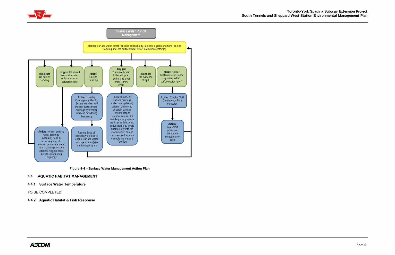
Toronto-York Spadina Subway Extension Project
South Tunnels and Sheppard West Station Environmental Management Plan
Page 29
Figure 4-4 – Surface Water Management Action Plan
4.4 AQUATIC HABITAT MANAGEMENT
4.4.1 Surface Water Temperature
TO BE COMPLETED
4.4.2 Aquatic Habitat & Fish Response

Toronto-York Spadina Subway Extension Project
South Tunnels and Sheppard West Station Environmental Management Plan
Page 30
Figure 4-5 – South Tunnels Storm Sewer Outfalls Map

Toronto-York Spadina Subway Extension Project
South Tunnels and Sheppard West Station Environmental Management Plan
Page 31
4.5 VEGETATION PROTECTION
During construction, the condition of the TPZs established around trees shall be monitored by a certified arborist twice annually during the growing season and periodically year-round for the duration of dewatering and recovery to ensure that they are functioning as designed. Plants found dead during dewatering and recovery will be replaced at an appropriate time of year, i.e., spring or fall.
Deficiencies should be reported and repaired in a timely fashion. Monitoring of the TPZs should include a provision to ensure the following activities are prohibited within TPZs:
Construction activities;
Altering of grade by adding fill, excavating, trenching, scraping, dumping, or disturbance of any kind;
Storage of construction materials, equipment, soil, construction waste, or debris;
Disposal of any liquids (e.g. concrete wash-out, gas, oil, etc.); and,
Movement of vehicles or machinery.
If temporary stockpiling is to be located near a TPZ, appropriate measures as determined by a certified arborist shall be installed to ensure no material enters the TPZ.
Overall tree health will also be monitored during construction by a certified arborist. This monitoring plan will be similar to the one used to monitor vegetation health in the woodlots and natural features.
Specific details regarding care and maintenance of plant materials, i.e., mulching and watering requirements, will be included in the Landscape Contracts.
4.6 WILDLIFE PROTECTION
4.6.1 Breeding Birds
If clearing and other construction activities can be planned outside of the breeding bird period, the risk of encountering nests and eggs is greatly reduced. If disruptive activities must occur during the breeding bird period, a detailed nest survey must be undertaken by a qualified biologist. Areas with active nests cannot be disturbed until the young have fledged. Where no active nests are found, disruptive activities may occur only within three (3) days of the survey. The survey must be repeated if the work is to take longer than three (3) days.
All cleared vegetation must be removed immediately from site as birds may nest in the piles and prevent
their removal until after the young have fledged.

Toronto-York Spadina Subway Extension Project
South Tunnels and Sheppard West Station Environmental Management Plan
Page 32
5. CONSTRUCTION CONTINGENCY PLANS
The following construction contingency plans were developed based on the TYSSE Risk Registrar developed by the TTC, TRCA and their consultants. These contingencies have been developed to address unanticipated events that may occur or be encountered during the Project undertaking. Mitigation measures have been developed for many of the contingency items in order to lower the possibility of situations that may cause delays in the Project schedule.
5.1 SPILL RESPONSE PLAN
A spill is defined in the Ontario EPA as a discharge “into the natural environment, from or out of a
structure, vehicle or other container, that is abnormal in quality or quantity in light of all the
circumstances of the discharge”. For the purpose of this EMP, such spills will be identified as major
spills, which must be reported to the MOE immediately. Minor spills can be expected on any
construction site, but do not need to be reported to the MOE and are to be mitigated and prevented.
This Spill Response Plan presents a detailed response system to deal with events such as the release
of petroleum, oils and lubricants or other hazardous liquids and chemicals, classified either as major or
minor spills. The objectives of the Plan are to minimize:
Danger to persons and adverse health effects;
Safety risk;
Impairment to the quality of the natural environment (air, water or land);
Extent of affected area;
Degree of temporary disturbance to the natural environment during work activities; and,
Injury or damage to property or animal life.
To reduce the likelihood of an event involving a spill or leak, the following procedures shall be followed:
All water control devices and hoses shall be inspected every five (5) hours and monitored to ensure proper working order;
All hoses and connections on equipment will be inspected routinely by truck operators for leaks and drips;
All equipment and vehicle leaks must be reported immediately to the Contractor and repaired prior to continued use;
All material storage areas shall be inspected every five(5) hours for signs of spills, general housekeeping, state of spill containment units and features, and availability of appropriate spill control supplies;
Automatic closures shall be used on all jerry cans;
Vehicles and equipment will be stored at designated areas a minimum of 30m from a watercourse;
Vehicle maintenance will be enhanced and good housekeeping practices will be implemented; and,
Water tight trucks or lined truck beds will be used to transport wet excavated material and debris that may otherwise leak.
Spill response kits (SRK) shall be maintained in areas that are accessible to all site personnel and shall
contain materials capable of containing and disposing of any spilled material that could occur during the
course of the Project undertaking. The SRK must contain the following spill response resources in order
to respond to accidental releases of fuels and/or hazardous materials.
EIL form and waterproof Emergency Contact Information sheet;
Absorbent materials (e.g., sorbent pads, Sorb-All, vermiculite);
Small hand equipment (e.g. shovels, tool kit, sledgehammer, buckets, tarpaulins, one empty drum;
Appropriate PPE;
Containment boom; and,
Fire extinguishers.
5.1.1 Minor Spills
Minor spills are spills of materials within the limits set out in the Transportation of Dangerous Goods Act
and the Classification and Exemption of Spills Regulation (O. Reg. 675/98) (CESR), as provided in
Table 5-1, which do not need to be reported to regulatory agencies. Note that spill reporting
exemption limits do not apply if the spilled material has entered or is adjacent to a watercourse
or water body, if the spill has crossed over to an adjacent property, or if a spill has occurred near
a structure that connects to a watercourse or water body. Any such spills must be treated as a
major spill.
In addition to the release of small quantities of materials (i.e. release less than the quantity identified in
Table 5-2, Section 5.1.2), the following are considered minor spills, according the rules set out in the
CESR:
Table 5-1 – Minor Non-Reportable Spills under Classification and Exemption of Spills Regulation
Item No. Class Description of Contaminant Quantity Spilled
1. i Discharges under a Certificate of Approval, order, license or other approval,
provided the discharge is in compliance with all legislation, including
municipal by-laws
NA
2. Ii Discharges of water from a reservoir caused by a natural event, and
discharges of potable water from water mains
NA
3. Iii Combustion products from household fires NA
4. Iv Planned spills and pre-authorized discharges (adverse effects must be
monitored and report filed within five days)
NA
5. v Spills of refrigerants governed by the Refrigerants Regulation (O. Reg.
189/94) – there must be no adverse effects and records must be kept
NA
5.1.2 Major Spills
Major spills must be reported to the MOE immediately and other stakeholders that may be impacted by
the spill (as noted in the following paragraphs). Any spills to or adjacent to a watercourse or near a
structure that connects to a watercourse must also be reported to the TRCA and DFO as per the
Federal Fisheries Act. In addition to the limits outlined below, a spill of the substances listed in Table 5-2
must be reported if the spill could pose a danger to public safety or the spilled substance enters a
watercourse or water body, or onto an adjacent property. The spills in excess of the following quantities
qualify as a major spill according to the CESR and the TDGA:

Toronto-York Spadina Subway Extension Project
South Tunnels and Sheppard West Station Environmental Management Plan
Page 33
Table 5-2 – Reportable Spill Exemption Limits
Item No.
Class Description of Contaminant Quantity Spilled
Transportation of Dangerous Goods Act
1. 1 Explosives >50kg
2. 2 Gases >10minutes
3. 3 Flammable Liquids >200L
4. 4 Flammable solids and substances liable to spontaneous combustion, water
reactive substances
>25kg
5. 5.1 Oxidising Substances >50kg or 50L
6. 5.2 Organic peroxides >1kg or 1L
7. 6.1 Toxic Substances >5kg or 5L
8. 6.2 Infections Substances >1kg or 1L
9. 7 Radioactive Materials NOTE (1)
10. 8 Corrosives >5kg or 5L
11. 9 Miscellaneous Products, Substances or Organisms >25kg or 25L
Classification and Exemption of Spills Regulation (O. Regulation 675/98)
12. vi Fluid, other than from cargo, from fuel or other operating systems or motor
vehicles
>100L
13. vii Mineral oil, other than PCB liquid, from transformers owned by municipal or
provincial utilities
>100L
14. viii Petroleum product from bulk plant, marina or private or retail outlet (if area is
restricted from public access)
>100L
15. viii Petroleum product from bulk plant, marina or private or retail outlet (if area is
publicly accessible)
>25L
16. x Materials itemized in site-specific spill contingency plan > volume
specified in
contingency plan
(1) Any quantity that could pose a danger to public safety and an emission level greater than the emission level established in Section
20 of the “Packaging and Transport of Nuclear Substances Regulation”
According to the contract documents, the Contractor is responsible and liable for all testing,
documentation, clean-up, reporting, repairs, removal, damages and associated costs and all other
actions arising from a major spill that resulted from Contractor(s) operations. To help mitigate potential
impacts, the Contractor(s) must maintain a SRK that is capable of disposing of any spill that could occur
during the course of the Project.
In the event of a major spill, the Contractor(s) shall immediately communicate the details of the spill,
including the type of spill, the quantity of the material spilled, the exact location of the spill and whether
the contaminant has entered any sewer line or floor drain or if the spill has occurred on unpaved ground,
to:
The Commission‟s representative
MOE Spills Action Centre;
The TRCA and DFO (if spill is a threat to or has entered a watercourse);
The municipality within the boundaries of which the spill has occurred, including municipal and regional governments; and,
The local fire department and police department (if the spill has entered a waterway, neighbouring property or public space (i.e. roadway).
Table 5-3 provides the contact information for the parties that may need to be contacted in the event of
a major spill.
Table 5-3 – Major Spill Contingency Contacts
Contact Contact Number
MOE Spills Action Centre 1-800-268-6060
TRCA 416-338-8888
DFO 613-993-0999
City of Vaughan, Public Works Dept. 905-832-8562
City of Toronto, Toronto Water 311
City of Toronto Fire Department 416-338-9050 (911)
Toronto Police Department 416-808-2222 (911)
In the event of a spill to a water course or water body, the Contractor shall work with the authorities in
coordinating a clean-up, which will include the following actions, where appropriate:
Deploy appropriately trained on-site personnel to contain the spilled material using absorbent material or booms, as appropriate;
Assess site conditions and environmental impact of various clean-up procedures;
Choose and implement an appropriate clean-up procedure;
Deploy on-site personnel to mobilize pumps and empty drums, or other appropriate storage, to the spill site;
Apply absorbents as necessary;
Remove any contaminated sediment/soil as required;
Dispose of all contaminated debris, water, soil, cleaning materials and absorbents generated by the clean-up operation to approved disposal site; and,
Take all necessary precautions to ensure that the incident does not reoccur.
5.1.3 General Spill Response Protocols
Spill response measures must be implemented quickly to limit the level of impact on the environment
and the work site; however, health and safety must be considered as the top priority when dealing with
spills. As such, in the event that a spilled material presents immediate danger to health and safety, all
workers shall be evacuated from the area until a full spill cleanup plan is developed. Similarly, if the
worker who discovers the spill is unaware of the properties of the substance that has leaked or spilled,
the worker shall immediately vacate the immediate area of the spill and notify their direct supervisor,
who shall investigate the incident.

Toronto-York Spadina Subway Extension Project
South Tunnels and Sheppard West Station Environmental Management Plan
Page 34
In standard spill situations, where there is no immediate threat to worker health and safety, upon the
discovery of the spill, the Contractor shall implement the following measures to mitigate the potential
impacts of the spill:
Obtain proper PPE and appropriate spill cleanup equipment (maintained at the material staging area and in any other area where hazardous liquids are handled or stored) to handle the spilled material;
Immediately cease that activity causing the spill, if possible;
Take appropriate action without unnecessary delay;
Cordon off or delineate the spill from the surrounding area (i.e. caution tape, signs or pylons);
Repair punctures or broken pipelines immediately (either temporarily or permanently) and/or implement other spill control measures;
Block any potential passageways to the excavation, creeks, drainage ditches, or catch basins;
Proceed to clean up the spill in accordance with the applicable legislation or retain an outside spill company to contain and clean the spill, if necessary;
Contact the Commission‟s Representative immediately and indicate whether the spill will impact Project construction activities, if the spill cannot be cleaned using on-site resources, or if the spill occurred in an unpaved area where potential impacts to underlying soil may have occurred;
Document all spills in an EIL including details with respect to the material spilled, volume, location, underlying material, clean-up required, materials used and any potential environmental impacts of the spill; and,
Submit the EIL to the Commission‟s Representative forthwith, along with a mitigative measures program. If the issue is not resolved in a reasonable period of time, as per the mitigative measures program developed by the Contractor, the Commission‟s Representative will take appropriate action.
If spill has occurred on a roadway, the Contractor(s) shall wait for police or fire department and do not
try to redirect the flow of traffic around the spill or attempt to contain or clean the spill unless:
The spill poses an immediate safety concern to the public or may cause immediate or acute environmental impact if not promptly contained or cleaned;
All necessary equipment for safely directing traffic is available (i.e. pylons, safety vests, hand-held “stop”/”slow” signs);
Someone is present who is trained in traffic control; and,
A minimum of two people are available to direct traffic.
5.2 SEVERE WEATHER
The Project work site must be maintained at all times such that materials are contained during regularly foreseeable weather conditions. Additional protocols must be implemented if greater than one-in-ten or one-in one-hundred year storms are forecasted. The potential impacts, preparation requirements, and response procedures for floods and severe weather are described below.
Flooding of work site could result from a failure of the dewatering program or a heavy rainfall event. Flooding has the potential to seriously disrupt work activities, endanger the safely of on-site workers, and could cause delays for clean-up activities to take place. Extreme water flows from heavy rainfall may also result in localized erosion of excavation embankments, carrying sediment-laden water into the work area.
All appropriate precautions shall be taken by Contractors to ensure that in the event of severe weather, the integrity of the Project and the safety of the workers will be maintained. These precautions include:
Ensuring that sufficient pump capacity is available to direct water flows away from the excavation and tunnels, both in the excavation and storm water management ponds;
Monitoring the weather forecast for the area to identify signs of severe weather from which flooding could result;
Maintaining emergency stand-by pumps that will be able to mitigate, to the greatest extent possible, any interference with construction works in the excavation as a result of flooding; and,
Storing all equipment and products away from active work areas and the excavation to prevent shifting and associated environmental consequences in the event of flooding.
In flood conditions, the subsequent procedures shall be followed:
On-site activities shall be temporarily ceased and active work areas shall be covered or protected from potential flow pathways using temporary berms. Emergency stand-by pumps shall be placed within the excavation and activated in advance of a potential flooding event where possible to prevent accumulation of water within the excavation;
If flooding occurs in the excavation, water remaining in the excavation after the event that caused the flooding shall be pumped and collected in ASTs or other suitable containment device for treatment, as directed by the Commission‟s Representative;
If flooding occurs or is imminent, all workers shall vacate potentially hazardous site areas, meeting in a safe area established by the Contractor(s);
Any harmful environmental effects resulting from flooding shall be assessed and if required, a restoration plan will be developed by the Contractor and reviewed by the Commission‟s Representative. A thorough investigation of structural integrity of the work area(s) shall also be conducted by the Commission‟s Representative in the event of a flood. Any spill of contaminated material shall be reported according to Section 4.1.2; and,
All incidents are to be reported to the Commission‟s Representative.
5.3 DEWATERING MALFUNCTION
It is possible that during construction pump failure may occur, resulting in dewatering malfunction. Pump failure could be a result of groundwater flows in excess of pump capacity, a mechanical failure within the pumping system or loss of power. The following outlines the procedures to be taken should this occur:
Cease and desist all construction activities that are affected by dewatering;
Check that power is being supplied to pumps;
Check that pumps are in working order;
Check water levels in nearby monitoring wells to determine if water entering the area is coming from an unexpected source;
If water is being obtained from unexpected source, contact hydrogeologist to conduct study to determine where the ground water is migrating from;
If malfunction is due by failure of emergency generator set or mechanical failure of pump, install replacement equipment;
If malfunction is due to increased water, install additional pumps for dewatering; and,
Construction is to resume when required water level has been met.

Toronto-York Spadina Subway Extension Project
South Tunnels and Sheppard West Station Environmental Management Plan
Page 35
5.4 CONTAMINATED GROUNDWATER INTO EXCAVATION
During construction, it is possible that contaminated water may enter the excavation. This water may come from a number of places, such as: construction site/surface runoff, groundwater infiltration, tunnelling spoils, and construction operations. The main sources of contamination are typically fuel and lubricants spills, contaminated soils, or contaminated groundwater drawn into the dewatering system. All water pumped from the excavations should pass through the on-site water treatment facility before being discharged; however, the system may not be designed to treat the unknown contaminants.
In the event that the contamination level causes the water discharging the treatment system to exceed the applicable criteria, the following steps should be taken:
Cease and desist discharge of water. Contain water within storage tanks or remove from the site for treatment;
Inspect the treatment system to ensure that the decrease in water quality is not due to equipment malfunction. If malfunction is the cause, repair the system and test to verify proper working order before continuing discharge. Resume sampling as per Section 4.1;
If decrease in quality is not due to malfunction, analyze inlet water for contaminants of concern. If concentrations are elevated or exceed discharge criteria, adjust the efficiency of the treatment system to meet the acceptable discharge limits. This may include installation of an additional system in series or the provision of sending the water to be treated off-site; and,
Discharge can resume only once discharge quality meets accepted discharge criteria.
In the event that the quantity of water from the excavation exceeds the capacity of the treatment system, the following steps should be taken:
Contain excess untreated water within storage tanks;
Increase treatment capacity including the installation of a secondary treatment system or additional primary units and to accommodate excess water; and,
Ensure that the discharge quantity is not exceeded. Quantities above the discharge limits may need to be treated off site.
In the event that the quantity of water accumulating in the excavation exceeds the capacity of the pumps and back-up pumps, the following steps should be taken:
Ensure that adequate power is being provided to the pumps;
Check that all pumps are in working order;
If the pumps are malfunctioning due to failure of emergency generator set or mechanical failure of pump, install replacement equipment; and,
If the existing pumps are in working order, install additional pumps to accommodate the excess water.
5.5 HANDLING, TREATMENT AND DISPOSAL OF SURFACE WATER ISSUES
Proactive mitigation and monitoring has been outlined for the handling of surface water. If storm water discharges exceed the applicable criteria (including temperature) at the respective discharge point (i.e. at storm sewer or storm outlet):
If possible, prevent further discharge of water from surface water control measures to the storm sewer or outlet and contain surface water;
Inspect surface water and sedimentation control measures to ensure functionality and repair any deficiencies;
Implement additional sedimentation and surface water control measures as approved by the Commission‟s Representative;
If the water does will not meet the desired temperature while flowing through the collection system either an aeration system will need to be installed within the receiving body of water, or water is to be discharged across an open field area at least 30m away from a watercourse. By utilizing one of these two methods, the temperature should adjust to the appropriate temperature. The aeration system will distribute the water across a greater area decreasing the effect of the warmer temperature; and,
Resume regular or modified operation of storm water management only after an appropriate solution has been implemented.

Toronto-York Spadina Subway Extension Project
South Tunnels and Sheppard West Station Environmental Management Plan
Page 36
APPENDIX A ENVIRONMENTAL INSPECTION LOG

Toronto-York Spadina Subway Extension Project
South Tunnels and Sheppard West Station Environmental Management Plan
Page 37
Appendix A
Environmental Inspection Log
Date (D/M/Y):_______________________________________ Time (24hrs):_________________________ Weather Conditions: _____________________________________________________________________________ Construction Status: _____________________________________________________________________________ Inspection Log Completed by (printed name and signature): _____________________________________________________________________________________________
CHECKLIST ITEM: ACCEPTABLE1 NOT ACCEPTABLE
1* NOT APPLICABLE
1. Sediment Control Structures
Heavy Duty Silt Fences
Jersey Barriers with Silt Fence
Staked Sediment Control Logs
Truck Wash
Mud Mat
Concrete Wash-Out Station
Storm Drain Inlet Protection
Sediment Traps
Temporary Rock Flow Check Dams
Other
8. Dewatering
Discharge Quality
Discharge Filters/Treatment System
Groundwater Level (excavations)
Groundwater Level (ecological)
9. Environmental Monitoring Activities
Surface Water
Aquatic Environment
Terrestrial Health
12. Other
13. Other 1
Criteria for Acceptable and Not Acceptable for each checklist item are given on Pages 3 to 7.
* Where a checklist item is not acceptable, comments must be provided below detailing: the nature of the concern; the extent of any environmental impacts; the remediation measures undertaken; the requirement for any further remediation measures; if notification of a regulatory body was required, and if so, the response; any recommendations for improvements/follow-up; and any other relevant information.
COMMENTS:
(Append additional pages if necessary)

Toronto-York Spadina Subway Extension Project
South Tunnels and Sheppard West Station Environmental Management Plan
Page 38
Criteria to Determine if Mitigation Effectiveness is Acceptable or Not Acceptable
1. Sediment Control Structures:
a. Acceptable:
i. During visual inspection, the sediment control structures are intact, with no gaps, tears, slumping or weathering of the materials and no noticeable impact in the receiving water “downstream” of the sediment control structures.
ii. During visual inspection, the reading/measurement is less than the specified Trigger Level as indicated in the table below.
b. Not Acceptable:
i. During visual inspection, the sediment control structures are not intact, with gaps, tears, slumping or weathering of the materials and noticeable impact in the receiving water “downstream” of the sediment control structures
ii. During visual inspection, the reading/measurement is greater than or equal to the Trigger Level as indicated in the table below. Remediation must be preformed within 24 hours of this inspection.
iii. If the reading/measurement is greater than or equal to the Action Level as indicated in the table below, work must halted and repairs to the sediment control structures must be preformed immediately.
Measure Trigger Level Action Level
Heavy Duty Silt Fence 30% full 50% full
Jersey Barrier with Silt Fence 30% full 50% full
Staked Sediment Control Log 30% of height 50% of height
Truck Wash As specified by Manufacturer O&M Manual
As specified by Manufacturer O&M Manual
Mud Mat 50% coverage 75% coverage
Concrete Wash-out Station 30% full 50% full
Inlet Sediment Control Device 15% full 30% full
Sediment Trap 15% full 30% full
Temporary Rock Check Dam 15% full 30% full
Sediment Control Pond 15% full 30% full
Erosion Control Blanket 30% full 50% full
Mulch 85% coverage <70% coverage
Hydroseed 85% coverage <70% coverage
2. Dewatering:
a. Acceptable: i. Groundwater quality at discharge meets or is less than applicable discharge criteria (i.e. municipal
sewer use by-law for storm or sanitary, PWQO requirements (storm sewer). ii. Treatment system is functioning effectively and is able to handle dewatering rates. Filters are below
80% of their maximum functioning capacity according to accompanying guidance manuals. iii. ZOI for temporary water table drawdown at site is equal to or less than predicted ZOI and/or
groundwater quantity at discharge meets or is less than predicted dewatering rate. Groundwater
levels are maintained at 0.5 - 1.0m below the invert of the shafts and 600mm below the excavation floor.
b. Not Acceptable:
i. Groundwater quality at discharge is at or greater than applicable discharge criteria (i.e. municipal sewer use by-law for storm or sanitary, PWQO requirements (storm sewer).
ii. Treatment system is unable to treat parameters of concern to below the applicable discharge criteria or is unable to process the volumes of water produced during dewatering. Filters are at or above 80% maximum functioning capacity according to accompanying guidance manuals.
iii. ZOI for temporary water table drawdown at site is greater than predicted ZOI and/or groundwater quantity at discharge is greater than predicted dewatering rate. Groundwater levels are less than 0.5 below the invert of the shafts (0.5m-0.70m = trigger; <0.0.5m = alarm) and less than 600m below the excavation floor (500mm = trigger; <500mm = alarm). At trigger level, pumping rates must be adjusted or increased while work is ongoing, at alarm level, work must cease until water levels reach 0.70m below the invert of the shafts and 550mm below the excavation floor.
iv. Soil moisture levels are temporarily (trigger) or consistently (alarm) below control area levels and/or tree or vegetative health are drought stressed (visual).
3. Environmental Monitoring Activities:
Surface Water
a. Acceptable: Surface water drainage collection system(s) is in good condition and function. No evidence of spills or on-site flooding. On site rain gauge is in good condition and function.
b. Not Acceptable: Surface water runoff drainage collection system(s) is not in good condition and not functioning as it should resulting in on-site-flooding and/or the release of sediment laden water into the natural environment. Evidence of spills. Rain gauge is in poor condition or not functioning
Aquatic Environment (only if groundwater is discharged to storm sewer system)
c. Acceptable: downstream water temperature (at outfall) is consistent with baseline or upstream, stream cross-sectional changes downstream of outfall reflect background trends and rates of change based on pre-construction data collection and upstream monitoring stations. Fish habitat and behaviour response consistent with baseline.
d. Not Acceptable: Water temperature downstream of outfall is +/- 5˚C of upstream (trigger) or a thermal barrier is present or the PWQO of +/- 10˚C of upstream is exceeded (alarm). Cross-sectional area changes downstream of outfall by more than 15% from previous measurement or bank erosion exceeds background rates and is a result of dewatering discharge (trigger). Cross-sectional areas downstream of discharge changes or increases in bank erosion rates are attributable to dewatering discharge as a result of dewatering discharge (alarm). Fish habitat is negatively altered and fish are displaying stress or avoidance behaviour.
Terrestrial Health
a. Acceptable: Visual survey by arborist does not reveal any concerns with respect to tree or vegetation health.
b. Not Acceptable: Visual survey by arborist reveals concerns with respect to tree of vegetation health (i.e. drought stress).

Toronto-York Spadina Subway Extension Project
South Tunnels and Sheppard West Station Environmental Management Plan
Page 39
APPENDIX B WEEKLY SUMMARY REPORT

Toronto-York Spadina Subway Extension Project
South Tunnels and Sheppard West Station Environmental Management Plan
Page 40
Weekly Summary Report
Week Ending (D/M/Y):_______________________________ Construction Status:_____________________________________________________________________________ Completed by (printed name and signature):__________________________________________________________ Were any elements found to be “Not Acceptable” according to the criteria of the Environmental Inspection Log (EIL) for the week ending indicated above?
Yes No If yes, list below:
ITEM1: Issue Identified Mitigative Measure Implemented
Follow-up Report
Received? (Y/N)
1 List of items identified for inspection on EIL is provided on following page
2 Commission’s Representative shall indicate whether the Contractor has completed a follow-up report regarding the incident. Follow-up
reports shall be appended to the weekly summary if possible or forwarded to the TTC when received.
COMMENTS:
(Append additional pages if necessary)

Toronto-York Spadina Subway Extension Project
South Tunnels and Sheppard West Station Environmental Management Plan
Page 41
APPENDIX C INCIDENT FOLLOW-UP REPORT

Toronto-York Spadina Subway Extension Project
South Tunnels and Sheppard West Station Environmental Management Plan
Follow-up report reviewed by ________________________ (company name) on _________________ (D/M/Y)
Incident Follow-up Report
Date of Report (D/M/Y):________________________ Date of Incident (D/M/Y):_______________________ Incident initially reported by:
Name Company
Follow-up Report Completed by:
Name Company Signature
Indicate the type of incident below (note that a separate follow-up report must be completed for each incident identified – check one only):
Incident Type Location
1. Sediment Control Structures
2. Stabilization Areas
3. General Noise Control Measures
4. General Air Quality Control Measures
5. Dewatering
6. Environmental Monitoring Activities
7. Access Roads
8. Other
Cause/Nature of Incident:
Mitigative Measures Implemented:
Current Status and Ongoing Monitoring:
(Append additional pages if necessary)