SOUTH BEND LATHE - VintageMachinery.orgvintagemachinery.org/pubs/1617/16497.pdf · 2016-10-31 ·...
84
SOUTH BEND LATHE
Transcript of SOUTH BEND LATHE - VintageMachinery.orgvintagemachinery.org/pubs/1617/16497.pdf · 2016-10-31 ·...

SOUTH BEND LATHE

f
l'A!taiog 5600, Copyright 1955 by the South Bend L"the Works. All rights reserved.

I 9 0 6 1956
50th Anniversary
It was in the fall of 1906 that twin brothers John J. and Miles W. O'Brien set up shop in a small building at South Bend, Indiana and began to design and build precision machine tools. Although bringing with them a rich heritage of Yankee ingenuity, their products were a success only after years of hard, painstaking effort and financial hardship. Both brothers had served toolmaker apprenticeships in some of the finest of the old New England shops. Later they supplemented their practical training with engineering courses at Purdue University and gained wide business experience with several well established machine tool manufacturers and distributors.
Recognizing the advantage of specialization, one of the first and most important decisions of the O'Brien brothers was to restrict their products to precision machine tools. It was this policy that enabled them to produce a b~tter machine at a better price. Through half a century there has been no deviation from this policy. Today, as in 1906, the entire resources and facilities of South Bend Lathe are devoted exclusively to the production of precision machine tools.
Operated first as a partnership and incorporated in 1914, the South Bend Lathe Works remained a closely held corporation until 1936 when its stock was first listed on the Chicago Stock Exchange, now the Midw:est Stock Exchange of Chicago. The stock is now owned by a diversified group of shareholders residing in all parts of the United States and several outside this country.
PLANT NO. 1
PLANT NO. 2
SOUTH BEND LATHE WORKS &Juildint/ &JeIki f!TooI4 9'uu;e ~90G --------
Cable address "TWINS" South Bend, South Bend 22, Indiana, .U.S.A.
Careful design and conscientious workmanship are combined in South Bend Lathes to give you a machine tool that you can depend on for years of satisfactory service. Continual research ~" has resulted in many improvements and ,-~,---
refinements which contribute to their ac-curacy, durability, and ease of operation. We know of no other lathe selling at anywhere near the price that can match the performance of South Bend.
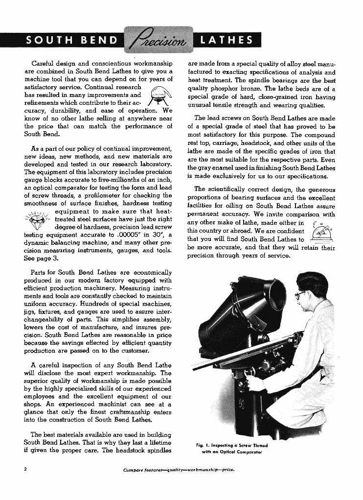
As a part of our policy of continual improvement, new ideas, new methods, and new materials are developed and tested in our research laboratory. The equipment of this laboratory includes precision gauge blocks accurate to five-millionths of an inch, an optical comparator for testing the form and lead of screw threads, a profilometer ~or checking the smoothness of surface finishes, hardness testing
,\.\1,// equipment to make sure that heat-:~- treated steel surfaces have just the right
deqree of hardness, precision lead screw testing equipment accurate to .()(X)()5" in 30", a dynamic balancing machine, and many other precision measuring instruments, gauges, and tools. See page 3.
Parts for South Bend Lathes are economically produced in our modem factory -equipped with efficient production machinery. Measuring instruments and tools are constantly checked to maintain uniform accuracy. Hundreds of special machines, jigs" fixtures, and gauges are used to assure interchangeability of parts. This simplifies assembly, lowers the cost of manufacture, and insures precision. South Bend Lathes are reasonable in price because the savings effected by efficient quantity production are passed on to the customer.
A careful inspeCtion of any South Bend Lathe will disclose the most expert workmanship. The superior quality of workmanship is made possible by the highly specialized skills of our experienced employees and the excellent equipment of our shops. An experienced machinist can see at a glance that only the finest craftsmanship enters into the construction of South Bend Lathes.
The best materials available are used in building South Bend Lathes. That is why they last a lifetime if given the proper care. The headstock spindles
LATHES
are made from a special quality of alloy steel manufactured to exacting specifications of analysis and heat treatment. The spindle bearings are the best quality phosphor bronze. The lathe beds are of a special grade of hard, close-grained iron having unusual tensile strength and wearing qualities.
The lead screws on South Bend Lathes are made of a special grade of steel that has proved to be most satisfactory for this purpose. The compound rest top, carriage, headstock, and oth~r units of the lathe are made of the specific grades of iron that are the most suitable for the respective parts. Even the gray enamel used in finishing South Bend Lathes is made exclusively for us to our specifications.
The Scientifically correct design, the generous proportions of bearing surfaces and the excellent facilities for oiling on South Bend Lathes assure permanent accuracy. We invite comparison with any other make of lathe, made either in I{ ~ this country or abroad. We are confident ~IJ that you will find South Bend Lathes to ~ _ _ be more accurate, and that they will retain their precision through years of service.
Fig. 1. Inspecting a Screw Thread
with an Optical Comparator
2 Compare /eoturel-qlUJlitv-workmonship-price.

Fig. 2. Testing Bed Ways with
Precision Straight Edge
Fig. 4 . Testing Heat-treatment
........ ...-..
....... T., .... __
fill '1.11 0;' IIlk· at. JlJl . 01\ -"--0( Lll Ok. '.
;=:)If--==----~ oK. nw.MDW.-_____ _
...... T_ ....... __ _
...,,.....~-"L-__
---t- --- ----- --~ --- ~ - -- ------ --
C-,_o-fiiIe. _~ __ """"~o-_ __ _ ____ _
IOUTH ... D LATH, ~KI '-Yo ...... -.. u.s. A..
Fig. 3. Testing Bed Ways with
Microscope and Tension Wire
Fig. 5. Factory Test Card. A
permanent record of the final
inspection tests for each lathe
is kept on a factory test card
similar to the one shown.
Fig. 6 . Checking Ac
curacy of Lead Screw
3
Underneath Motor Drive PROVIDES SMOOTH POWER
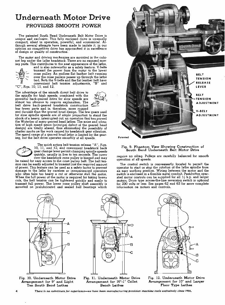
The patented South Bend Underneath Belt· Motor Drive is unique and exclusive. This fully enclosed drive is unusually compact, silent in operation, powerful, and economical. Although several attempts have been made to imitate it, in our opinion no competitive drive has approached it in excellence of design or quality of construction.
The motor and driving mechanism are mounted in the cabinet leg under the lathe headstock .. There are no exposed moving parts. This contributes to the neat appearance of the lathe,
.... t· /' - , -- -/ -"
and is also noteworthy as a safety feature. V-belts transmit the power from the motor to the lower cone pulley. An endless flat leather belt running over the cone pulleys passes up through the lathe bed. Both the V-belts and the flat leather belt have convenient belt tension adjustments, "B" and
"C", Figs. 10, 11, and 12.
The advantage of the smooth direct belt drive to the spindle for high speeds, combined with the powerful back-geared drive for slow speeds are almost too obvious to require explanation. The belt drive back-geared headstock construction has fewer parts and is, therefore, more rugged
~ -=----:' •
~ ---and durable than the geared head design. The few gears used for slow spindle speeds are of ample proportion to stand the shock of a heavy, interrupted cut; an operation that has proved the Waterloo of many geared head lathes. The noise and vibration 'of high speed gears (principal defect of the geared head design) are totally absent, thus eliminating the possibility of chatter marks on the work caused by headstock gear vibration. The speed range of a geared head lathe is limited by the gearing, but the belt drive operates smoothly at all speeds.
The quick acting belt tension release "A", Figs.
(!) 10, 11, and 12, and convenient headstock back o gear change lever permit changing spindle speeds
quickly, usually in five to ten seconds. The cover over the headstock cone pulley is hinged and may
be raised for easy access to the cone pulley belt. The belt tension can be easily adjusted to transmit just the required amount of power. This feature can be used as a safety factor to prevent damage to the lathe by careless or inexperienced operators who often take too heavy a cut or otherwise stall the motor. When the full power of the motor is required for taking heavy cuts, the belt tension can be tightened quickly and easily to transmit full power. The lower cone pulley shaft assembly is mounted on prelubricated and sealed ball bearings which
IIH-+----tlt--c
B
TENSION
ADJUSTMENT
ADJUSTMENT
Patented
Fig. 9. Phantom View Showing Construction of South Bend Underneath Belt Motor Drive
require no oiling. Pulleys are carefully balanced for smooth operation at all speeds.
The control switch is conveniently located to permit the operator to start or stop the rotation of the lathe spindle from an easy working position. Wiring between the motor and the switch is enclosed in a flexible metal conduit. Pushbutton oper-. ated motor controls can be supplied for all 72 h .p . and larger motors. Drum type across-the-line reversing switch is optional for 230 volts or less. See pages 62 and 63 for more complete information on motors and controls.
A
B
C
Fig. 10. Underneath Motor Drive Arrangement for 9" and Light
Ten South Bend Lathes
Fig. 11. Underneath Motor Drive Arrangement for 10"-1 " Collet
Bench Lathes
Fig. 12. Underneath Motor Drive Arrangement for 10" and Larger
noor Type Lathes
4 ·There is no substitute for experience-we have been manufacturing precision machine tool. exclusively since 1906.

The Much Imitated' Quick Change Box
No sooner had this improved quick change mechanism been placed on the market than imitations began to appear. A number of manufacturers have attempted to duplicate it- and have succeeded as far as appearance is concerned. But only genuine South Bend equipment has the quality of design, workmanship, and materials to give you the convenience, ease of operation, and the long, dependable service you have a right to expect. It took years of research and testing- actual use on tough jobs in our own shop- to develop a rugged foql-proof mechanism entirely satisfactory from the operators' standpoint.
A direct reading index chart shows positions in which the two conveniently located tumbler levers are placed for each of 48 screw thread pitches, 48 power longitudinal feeds, and 48 power cross-feeds. • There are no sliding clutches or sliding primary end gears to change. Shifting a single lever changes feed instantly from coarse to fine, for roughin9 or finishing cuts.
Standard screw threads from 8 to 224 per inch are obtained by shifting the two tumbler levers on the gear box. The stud gear is changed for an additional series of coarse pitches rang-
Fig. 13. Improved Quick Change . Box for South Bend Lath811
Fig. 14. Interior of Improved Quick
Change Box
ing from 4 to 7 threads per inch. Provision is made for the use of special stud and intermediate gearing needed to cut metric screw threads, diametral pitch worm threads, or other special screw threads. Metric transposing gears are listed on page 61. Prices of extra stud gears for special threads will be quoted on request. State pitches of threads to be cut.
The main frame of the gear box consists of a heavy one-piece casting which is attached to the lathe bed near the headstock. Special quality alloy steel is used for all gears and shafts. Gears are precision-cut for maximum accuracy and quiet operation. Shafts are carefully ground and fitted . The lead screw shaft revolves in an annurar ball bearing and has a precision thrust bearing to eliminate end play and cam action. Tumbler gears are fitted with needle bearings.
° 10"- 1" Collet Lathes have 70 changes, cut 70 screw thread. 4 to 480 'per inch. See page 19.
MANurACT URED BY SOUTH BEND LATHE WORKS SOUTH BEN D IND lJ S A
SluG un THREAD S PER !NC H
14, & 16 . /\I ett SOUTH BEND I'=""'":::j 0 GUll HaN D fEEDS IN· THOUSANDTHS ... TUIIIBWI
I~ ::: 4 4 '. 5 5 5 ' 6 6 -PRECISION lATHE B" 48 A
BfNO I oJ 0641 0748 0('73 Ot:.> ·I.~ OS65 05(,1 OS '8
MODEL A '-'-,;..:..:.,J ... q 8 ... Z
A 9 10 11 1" 12 13 ~c 24 0421 0314 OJ -j7 OlOb 0293 0260 025<)
C ATALOG NO - ", :0
"'~ 24 B 16 18 20 22 23 24 26 BED LENGTH - ~:; 0210 016 1 01 '~B 0' ~) 0146 0140 O' £9
u Z C HAR T NO , 0 24 C 32 36 40 44 46 48 52
o: J 0105 00'1] OOA4 0010 0073 D070 on':i5 "'if> ;: ... 24 0 6 4 72 30 88 92 96 104 0:1' 0053 0047 0')4;.' 0').18 00'17 OOJ~:' OQ'I2 Q.~
: 24 E 128 144 160 ~6?,. 1I' 184 '92 208 QO~6 00,'.1 00.'1 o:~· !j 00 1 7 0')''-,
II i i C 0 E:=
Fig. IS. Direct Reading Index Chart Showing Threads and Feeds Provided by Quick Change Mechanism on 16-inch Swing Lathe
7 QolO!
14 O~'40
28 0' .?'J
56 (JD'.'J
112 '·'1_1
224 ,
II ir.
ME TRIC TH READS-Metric lead screw and gear bo" or metric transposing gears (page 61) can be supplied with any South Bend lAthe. 5
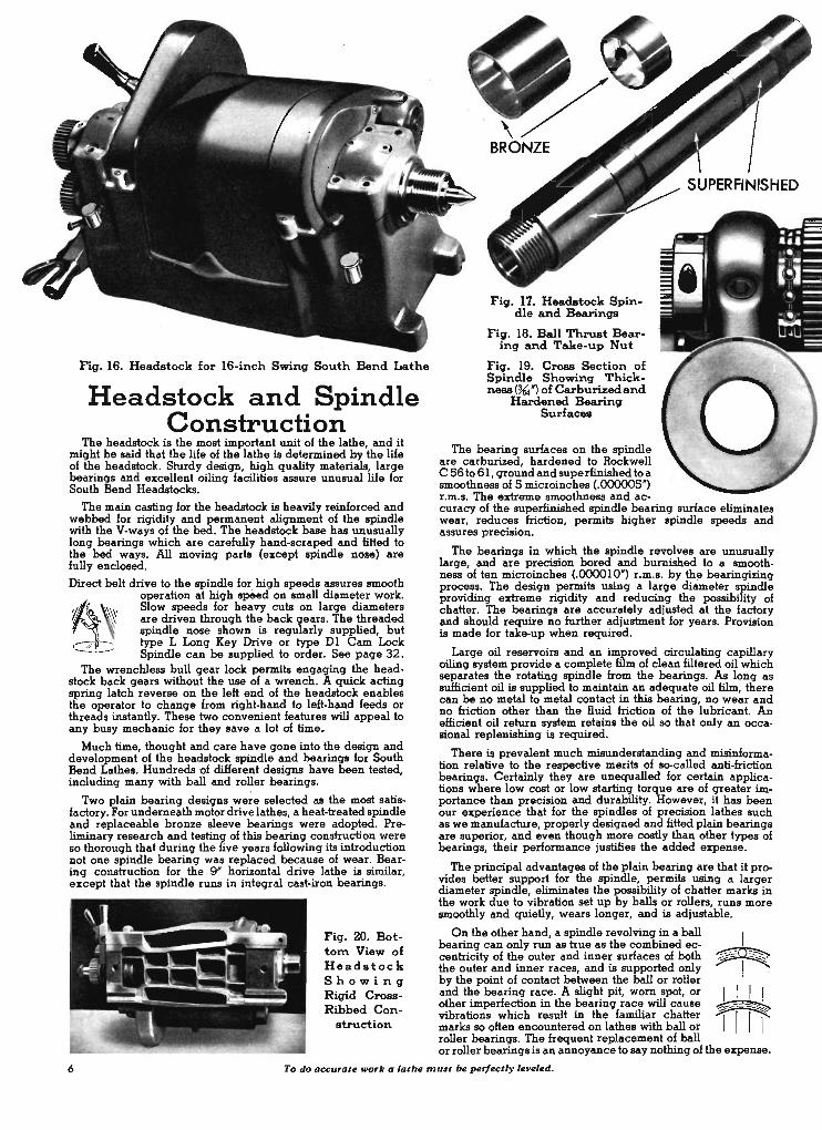
Fig. 16. Headstock for l6-inch Swing South Bend Lathe
Headstock and Spindle Construction
The headstock is the most important unit of the lathe, and it might be said that the life of the lathe is determined by the life of the headstock. Sturdy design, high quality materials, large bearings and excellent oiling facilities assure unusual life for South Bend Headstocks.
, The main casting for the headstock is, heavily reinforced and webbed for rigidity and permanent alignment of the spindle with the V-ways of the bed. The headstock base has unusually long bearings which are carefully hand-scraped and fitted to the bed ways. All moving parts (except spindle nose) are fully enclosed.
Direct belt drive to the spindle for high speeds assures smooth operation at high sp8ed on small diameter work.
'~/,~ __ ~\\: Slow speeds for heavy cuts on large diameters I~ ~ are driven through the back gears. The threaded
spindle nose shown is regularly supplied, but type L Long Key Drive or type D 1 Cam Lock
- .- Spindle can be supplied to order. See page 32 . The wrenchless bull gear lock permits engaging the head
stock back gears without the use of a wrench. A quick acting spring latch reverse on the left end of the headstock ,enables the operator to change hom right. hand to left·hand feeds or threads instantly. These two convenient features will appeal to any busy mechanic for they save a lot of time.
Much time, thought and care have gone into the design and development of the headstock spindle and bearings for South Bend Lathes. Hundreds -of different designs have been tested, including many with ball and roller bearings.
Two plain bearing designs were selected as the most satisfactory. For underneath motor drive lathes, a heat-treated spindle and replaceable bronze sleeve bearings were adopted. Preliminary research and testing of this bearing construction were so thorough that during the five years following its introduction not one spindle bearing was replaced because of wear. Bear· ing construction for the 9" horizontal drive lathe is similar, except that the spindle runs in integral cast·iron bearings.
Fig. ZO. Bottom View of Headstock S h 0 wi n 'g Rigid CroBBRibbed Con-
struction
Fig. 17. Headstock Spindle and Bearings
Fig. 18. Ball Thrust Bear-ing and Take-up Nut
Fig. 19. CroBB Section of Spindle Showing ThickneBS (~') of Carburizedand
Hardened Bearing Surfaces
The hearing surfaces on the spindle are carburized, hardened to Rockwell C 56 to 61, ground and superfinished to a smoothness of 5 microinches (.000005") r.m.s. The extreme smoothness and ac· curacy of the superfinished spindle bearing surface eliminates wear, reduces mction, permits higher spindle speeds and assures precision.
The bearings in which the spindle revolves are unusually large, and are precision bored and burnished to a smoothness of ten microinches (.000010") r.m.S. by th~ bearingizing process. The design permits using a large diameter spindle providing extreme rigidity and reducing the possibility of chatter. The bearings are accurately adjusted at the factory and should require no further adjustment for years. Provision is made for take-up when required.
Large oil reservoirs and an improved circulating capillary oiling system provide a complete film of clean filtered oil which separates the rotating spindle hom the bearings. As long as sufficient oil is supplied to maintain an adequate oil film, there can be no metal to metal contact in this bearing, no wear and no mction other than the fluid mction of the lubricant. An efficient oil return system retains the oil so that only an occasional replenishing is required.
There is prevalent much misunderstanding and misinformation relative to the respective merits of so-called anti-mction bearings. Certainly they are unequalled for certain applications where low cost or low starting torque are of greater importance than precision and durability. However, it has been our experience that for the spindles of precision lathes such as we manufacture, properly designed and fitted plain bearings are superior, and even though more costly than other types of bearings, their performance justifies the added expense.
The principal advantages of the plain bearing are that it provides better support for the spindle, permits using a larger diameter spindle, eliminates the possibility of chatter marks'in the work due to vibration set up by balls or rollers, runs more smoothly and quietly, wears longer, and is adjustable.
On the other hand, a spindle revolving in a ball hearing can only run as true as the combined eccentricity of the outer and inner surfaces of both the outer and inner races, and is supported only by the point of contact between the ball or roller and the bearing race. A slight pit, worn spot, or other imperfection in the bearing race will cause vibrations which result in the familiar chatter marks so often encountered on lathes with ball or roller bearings. The hequent replacement of ball
I ~D~
I I I I ~~ I 111
or roller bearings is an annoyance to say nothing of the expense.
6 To do accurate work a lathe must be perfectly leveled.
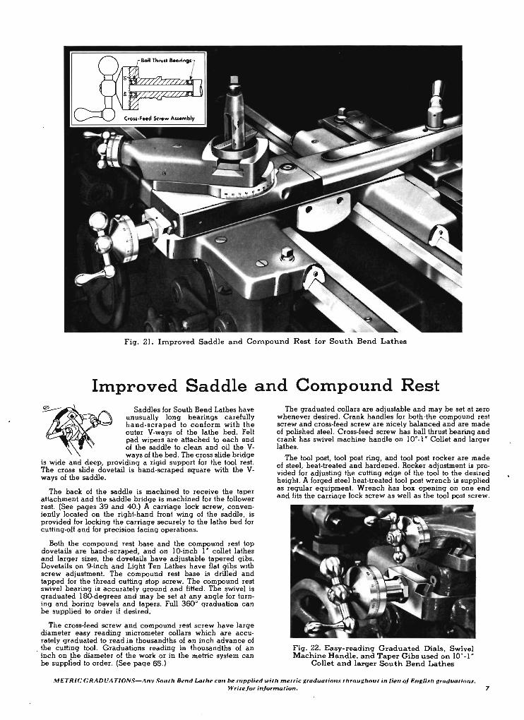
Fig. 21. hnproved Saddle and Compound Rest for South Bend Lathes
Improved Saddle and Compound Rest Saddles for South Bend Lathes have
unusually long bearings carefully hand· scraped to conform with the outer V-ways of the lathe bed. Felt pad wipers are attached to each end of the saddle to clean and oil the Vways of the bed. The cross slide bridge
is wide and deep, providing a rigid support for the tool rest. The cross slide dovetail is hand-scraped square with the Vways of the saddle.
The back of the saddle is machined to receive the taper attachment and the saddle. bridge is machined for the follower rest. (See pages 39 and 40.) A carriage lock screw, conveniently located on the right-hand front wing of the saddle, is provided for locking the carriage securely to the lathe bed for cutting-off and for precision facing operations.
Both the compound rest base and the compound rest top dovetails are hand-scraped, and on 10-inch I " collet lathes and larger sizes, the dovetails have adjustable tapered gibs. Dovetails on 9-inch and Light Ten Lathes have flat gihs with screw adjustment. The compound rest base is drilled and tapped for the thread cutting stop screw. The compound rest swivel bearing is accurately ground and fitted. The swivel is graduated ISO-degrees and may be set at any angle for turning and boring bevels and tapers. Full 360° graduation can be supplied to order if desired.
The cross-feed screw and compound rest screw have large diameter easy reading micrometer collars which are accurately graduated to read in thousandths of an inch advance of
. the culling tool. Graduations reading in thousandths of an inch on !he diameter of the work or in the metric system can be supplied to order. (See page 65.)
The graduated collars are adjustable and may be set at zero whenever desired. Crank handles for both ·the compound rest screw and cross-feed screw are nicely balanced and are made of polished steel. Cross-feed screw has ball thrust bearing and crank has swivel machine handle on 10"-1 " Collet and larger lathes.
The tool post, tool post ring, and tool post rocker are made of steel, heat-treated and hardened. Rocker adjustment is provided for adjusting the cutting edge of the tool to the desired height. A forged steel heat-treated tool post wrench is supplied as regular equipment. Wrench has box opening on one end and fits the carriage lock screw as well as the tool post screw.
Fig. 22. Easy-reading Graduated Dials, Swivel Machine Handle, and Taper Gibs used on 10' -1 "
Collet and larqer South Bend Lathes
METRJC GRADUATIONS-Any South Bend Lathe ca" be .wpplied with metric graduotioru throughout in lieu 0/ Engli .• h graduations. Write/orin/ormation_ 7
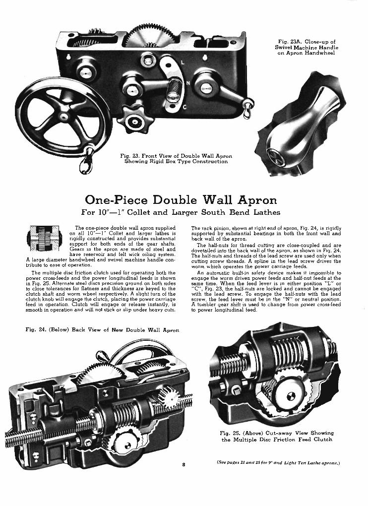
Fig. 23A. Close-up of Swivel Machine Handle on Apron Handwheel
Fig. 23. Front View of Double Wall Apron Showing Rigid Box Type Construction
One-Piece Double Wall Apron For 10"-1" Collet and Larger South Bend Lathes
The one-piece double wall apron supplied on all 10"- 1" Collet and larger lathes is rigidly constructed and provides substantial support for both ends of the gear shafts. Gears in the apron are made of steel and have reservoir and felt wick oiling system.
A large diameter hand,wheel and swivel machine handle contribute to ease of operation.
The multiple disc friction clutch used for operating both the power cross-feeds and the power longitudinal feeds is shown in Fig. 25. Alternate steel discs precision ground on both sides to close tolerances for flatness and thickness are keyed to the clutch shaft and worm wheel respectively. A slight turn of the clutch knob will engage the clutch, placing the power carriage feed in operation. Clutch will engage or release instantly, is smooth in operation and will not stick or slip under heavy cuts.
Fig. 24_ (Below) Back View of New Double Wall Apron
The rack pinion, shown at right end of apron, Fig. 24, is rigidly supported by substantial beat~ngs in both the front wall and back wall of the apron.
The half-nuts for thread cutting are close-coupled and are dovetailed into the back wall of the apron, as shown in Fig. 24. The half-nuts and threads of the lead screw are used only when cutting screw threads. A spline in the lead screw drives the worm which operates the power carriage feeds .
An automatic built-in safety device makes it impossible to engage the worm driven power feeds and half-nut feeds at the same time. When the feed lever is in either position "L" or "C", Fig. 23, the half-nuts are locked and cannot be engaged with the lead screw. To engage the half-nuts with the lead screw, the feed lever must be in the "N" or neutral position. A tumbler gear shift is used to change from power cross-feed to power longitudinal feed.
Fig. 25. (Above) Cut-away View Showing the Multiple Disc Friction Feed Clutch
(Seepages 21 and 2SIor 9" and Light Ten Lathe aprons. )
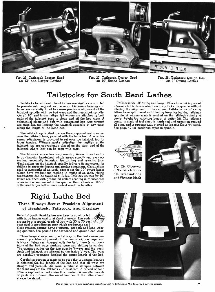
Fig. 26. Tailstock Design Used on 13" and Larger Lathes
Fig. 27. Tailstock Design Used on 10' Swing Lathes
Fig. 28. Tailstock Design Used on 9" Swing Lathes
Tailstocks for South Bend Lathes Tailstocks for all South Bend Lathes are rigidly constructed
to provide solid support for the work. Generous bearing surfaces are carefully fitted to assure precision alignment of the tailstOck spindle with the bed ways and the headstock spindle. On all 10' and larger lathes, felt wipers are attached to both ends of the tailstock base to clean and oil the bed ways. A substantial clamp and bolt with convenient box type wrench are provided for locking the tailstock securely at any point along the length of the lathe bed.
The tailstock top is offset to allow the compound rest to swivel over the tailstock base, parallel with the lathe bed. A sensitive screw adjustment is provided to set over the tailstock top for taper turning. Witness marks indicating the position of the tailstock top are conveniently placed on the right end of the tailstock where they can be seen with ease.
The tailstock screw has long wearing Acme thread and a large diameter handwheel which assure smooth and easy operation, especially important for drilling and reaming jobs. Graduations on the tailstock spindle indicate its movement for drilling to accurate depths and similar operations. Graduations read in sixteenths of an inch, except for the 10' swing lathes which have graduations reading in tenths of an inch. Metric graduations can be supplied to order. Tailstock screws for 10' lathes are fitted with graduated collars reading in thousandths of an inch advancement of the spindle. Handwheels on 10'-1" collet and larger lathes have swivel machine handles.
Rigid Lathe Bed Three V -ways Assure Precision Alignrnen t
of Headstock, Tailstock, and Carriage
Beds fot South Bend Lathes are heavily constructed I!;with large braces cast in at short intervals. The beds .--~'; _ " /{I
are made of a special grade of iron with 30 to 70 per .'; I . ,<
cent steel (depending on size) which produces a hard • close-grained ca.sting having unusual strength and long wearing qualities. See page 34 for hardened and ground bed ways.
Three large V-ways and one fiat way on the bed assure permanent precision alignment of the headstock, carriage, and tailstock. Being cast integral with the bed, there is no possibility of the bed ways working loose and shifting in service. The carriage slides on the two outside V-ways and the headstock and tailstock are aligned by the inside V-way. The ways are carefully precision finished the entire length of the bed.
Careful inspection is made to be sure that a uniform bearing is obtained the full length of the bed and that all ways are straight and parallel. The serial number is stamped between the front ways at the tailstock end as shown. A record of each lathe is kept and is filed under this number. When attachments or parts are ordered, the serial number of the lathe should always be stated.
Tailslocks for 10' swing and larger lathes have an improved inlernal clutch device which securely locks the spindle wilhoul allering Ihe alignment of Ihe centers. Tailslocks for 9 ' swing lathes have split barrel and binding lever for locking tailslock spindle. A witness mark is scribed on the tailslock spindle at center height for adjusting height of cutter bi!. The lailslock center is made of 1001 sleel, is hardened and precision ground allover, and is automatically ejected as Ihe spindle is retracted. See page 47 for hardened laper in spindle.
Fig. 29. Close-up of Tailstock Spindle Graduations and Witness Mark
Use a mixture oj red lead and machine oil to lubricate the tail. tack center point. 9

'7/DO ~ rr- {5 H P .
2--- /0
16" So'::;;;:~'I'C: ties~p4 TOOLROOM and ENGINE LATHE MODELS
Five Bed Lengths-33" to 105" Between Centers
We sincerely believe that this is the finest lathe of this size and type that you can buy at anywhere near the price. Capable of the most exacting operations, it has ample power and capacity for most toolroom and production jobs. Special accuracy tests are made on each lathe during the assembling and testing to assure utmost precision. Husky castings and large, carefully fitted bearings provide the rigidity so essential to smooth operation and a durability that assures long We.
16' Swing South Bend Precision Engine Lathe with Center Leg
Chip 'an I. extra . s •• palle 45 .
Made in both toolroom and engine lathe models, you have a choice of five bed lengths providing 33 H to IOSH between centers. Hardened and ground bed ways, cam lock spindle nose, or long taper key drive spindle nose can be supplied in lieu of regular equipment at small extra cost. See pages 32 and 34.
TWO TYPES OF HEADSTOCKS Six to Sixteen Spindle Speeds
Headstocks for 16H swing South Bend Lathes are made in two types: 4-step cone pulley and wide belt 3-step cone pulley. The 4-step cone pulley headstock provides either eight or sixteen spindle speeds depending on whether a single-speed or a two-speed motor is used. With the wide belt 3-step cOne pulley you have either six or twelve spindle speeds.
The 4-step cone pulley design is well adapted to toolroom work and finishing operations as it provides a greater selection of spindle speeds.
10 You can't go wrong-when you select a South Bend.

The wide belt 3-step cone pulley headstock assures maximum power transmission for heavy roughing cuts and rapid production. It is especially recommended for use with a two-speed motor.
Quick Changefroll\ High to Low-Speeds
When a two-speed motor is used it doubles the number of spindle speeds, providing sixteen speeds with the 4-step cone pulley or twelve speeds with the 3-step cone pulley headstock. This not only increases the speed range but with . push button control it provides instantaneous changes between corresponding high speeds and low speeds. This feature saves time on ~ultiple operations requiring frequent speed changes such as drilling and tapping, boring and reaming, or turning and facing. The low spindle speeds are approximately one-half the corresponding high speeds. See page 62 for information on motors and controls.
A. Th-. • ..,. co ... pvlley h ........ ek, _eh • ..,. 3' wid. I . Four-• ..,. co ... pvlley head.tock, _ch • ..,. 2'A ' wide C. Com lock spindle. See _ 32 D. Lo", to_ key drive spI ..... See _ 32
ENGINE LATHES Regular equipment included in price of each 16' Engine
Lathe consists of: 4 V-belts; flat leather belt; thread indicator dial; small face plate; heat-treated steel tool post; adjustable thread cutting stop; tool steel centers for headstock and tailstock spindles; headstock spindle sleeve; wrenches; quick change box; installation plan; and book "How to Run a Lathe". Electrical equipment is not included in price of lathe. See page 62 for information on motors and controls.
NCautamlb~ I L!.':th I ~:= I Ct~ I :::~t I ~~t I Factory - Feet Inch.. Boxed Pound. Pounda Price
18' Engine Lath .. with THREE·STEP Pulley Headatock
CL155C 6 33 89 2775 2315 $2259 CL156D 1 45 96 3025 2455 2314 CLl56E 8 51 IDS 3225 2535 2369 CL156G ID" 81 123 3625 2815 - 2527 CLl56H 12* IDS 141 3915 3050 2685
18' Engine Lathe. with FOUR·STEP Pulley Heedllock
CLl17C 6 33 89 2100 2300 $2259 CL117D 1 45 96 2950 2380 2314 CL117E 8 51 IDS 3150 2460 2369 CLl17G ID" 81 123 3550 2800 2527 CL117H 12* 105 141 3900 2915 2685
*Center leg is supplied with 10' and 12' beds.
TOOLROOM LATHES Regular equipment included in price of each 16' Toolroom
Lathe is the same as listed above for the Engine Lathe. In addition, the following toolroom attachments are supplied: precision lead screw; handwheel type draw·in collet attach· ment (without collets); collet rack; telescopic taper attachment; large face plate; chip pan; and micrometer carriage stop. Electrical equipment is not included in price of lathe. See page 62.
Catalog I L!~th I ~:= I CF~tC I :'::~t I ~= I Factory Numb.. Feet Inch.. Boxed Poundl Pound. Price
CL8155C CL81560 CL8156E
CL8117C CL8117D CL8117E
18' Toolroom Lath .. with THREE-STEP Pulley Heedatock
33 I 100 45 106' 51 . 111
3000 3250 3450
2600 2680 2160
$2806 2869 2932
18' Toolroom Lath .. with FOUR-STEP Pulley H .. datock
6 1 8
33 45 51
100 106 111
;~~~ I ~~~ l $~: 3315 2685 -r 2932
SPECIFICATIONS CAPACITY OF LATHE
Swing over bed and saddle wings ..........•..... . . . ....... .. ..... · . ...... 16~' Swing ov.r saddle cross slide ..... . .......... . . ... ........... .. .. ...... . . 9%' Swine over cross slid. without chip guard, engine lath. mod.1 only .... .. .. . . 1l~'
SPINDLE SPEEDS (approximate, not .xact) Direct Drlv. Back-Geared
With 4-Step Cone Pulley Headstock High speeds, r.p.m .......... . ........... 980,610,390,240 125, 80, 50, 30 low speeds. available only with
2·speed motor, r.p.m ..... ... . ......... 490, 305, 195, 120 62, 40, 25, IS With 3-step con. pulley headstock
High speeds, r.p.m...................... 945, 550, 300 118, 10, 32 low speeds, available only with
2-speed motor, r.p.m.... . . . .......... . 415, 278, 150 50, 33, 20
HEADSTOCK Hole through spindle ...• . ....... . ...................................... . I~' Maximum collet capacity .. . . .. ... . ..... ... ....... ......... .... . .......... ".1' Spindle nos. diameter and threads ...•........ .. ...... .. ...... .. ..... .. . 2~'-6 SIZe of center. Morse taper. ........... . ........ . ............ . .. . ... . .. .. No. 3 Width, each step of 4' step cone pull.y ... . .. ....• . . . ....... . ... . . . .... .. ... 2~' Width, each step.of 3-step con. pulley ..... . .. . ........ . . . .......... . ........ j' large fac. plate diameter. ...... . ..... . . . ..........•.... .. .......••..... 13~' Small face plate diameter .•. .•.. ..... ... .............. . . ....... ... ....... 8\{,' Front spindle bearing diameter . . .. .. ...........••. . .. ...... . .. . .. ... ..... 2~'
TAILSTOCK Size of center, Morse taper .............. ............ ................. , .. No.3 Spindle traveL ..... . ........... ..... . . . .......... ...... . .......... . . . .. 5~' Each graduation on tailstock spindle . . ....... . . ............... .. . .. .... . ... \{,' Tailstock top set-over for taper turning ........ . .......... . ......... . ... . ... . 1'
COMPOUND REST Cross slide travel. engine lathe modeL ... . ... . . . •............. ..••. ..... . IO~' Cross slide travel , tool room mod.I.. .. . .. . ......... .... ..... . . . . .. . . .... . IO\{,' Angular hand feed of compound rest top slid • . : ...... ..... . .... . .•.... . .... 3~'
THREADS and FEEDS Thread cutting rang&-48 pitches R.H. or LH... . . . . . . . . . . . . . . .. 4 to 224 per ;-nch longitudinal feeds through friction clutch- •
48 feeds R.H. or l.H ....... .. .. . .............. . . . .. .......... 0015' to .0841' Cross-feeds through friction clutch--48 feeds ... . ......... : ....... 0006' to .0315' lead screw, 29" Acme thr.ad . . .. . .. .. ........... . .. ... , ..... I~' dia .~ thrds.
TOOL POST Size of tool holder shank opening will tak • ...... . . .... . ............... %' x I~' Size of cutter bit tool hold.r will take .. . ' .......... . .... . . . . .. .......... ~' sq.
MOTOR (recommended liz.) Four-st.p con. pull.y. on.-speed motor . ...•. . .. . .. . . ..... ............. I~ h.p. Three-step con. pulley. on.·speed motor ................... . .•...•..... . . 2 h.p. Three- or four-step con. pulley. two-speed motor .. . ...• . ....... .. .... . .. 2-1 h.p.
SOllth Bend-tM mo.t copied lothe in the world. 11
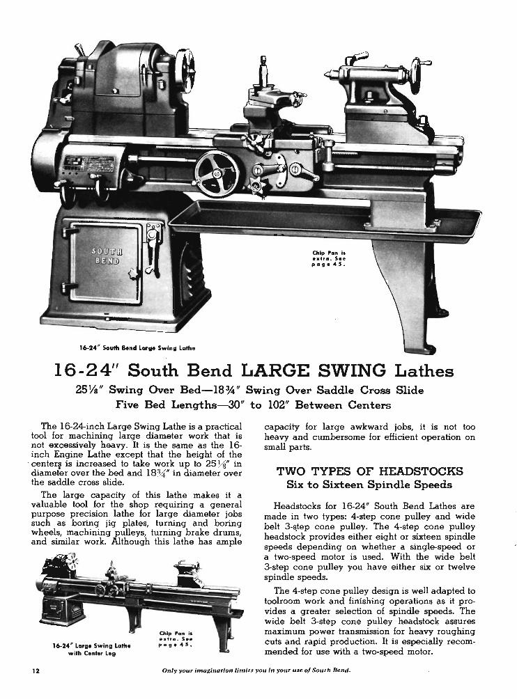
16-24' South Bend Large Swing Lathe
Chip ran is extra. See palle 45.
16-24" South Bend LARGE SWING Lathes 25 Ys" Swing Over Bed-18 *" Swing Over Saddle Cross Slide
Five Bed Lengths-30" to 102" Between Centers
The 16-24-inch Large Swing Lathe is a practical tool for machining large diameter work that is not excessively heavy. It is the same as the 16-inch Engine Lathe except that the height of the
. center!j is increased to take work up to 25 Ys" in diameter over the bed and 18%:," in diameter over the saddle cross slide.
The large capacity of this lathe makes it a valuable tool for the shop requiring a general purpose precision lathe for large diameter jobs such as boring jig plates, turning and boring wheels, machining pulleys, turning brake drums, and similar work. Although this lathe has ample
16-24 ' Large Swing Lathe with Center Leg
Chip Pan is extra , See page 45.
capacity for large awkward jobs, it is not too heavy and cumbersome for efficient operation on small parts. .
TWO TYPES OF HEADSTOCKS Six to Sixteen Spindle Speeds
Headstocks for 16-24" South Bend Lathes are made in two types: 4-step cone pulley and wide belt 3-~tep cone pulley. The 4-step cone pulley headstock provides either eight or sixteen spindle speeds depending on whether a single-speed or a two-speed motor is used. With the wide belt 3-step cone pulley you have either six or twelve spindle speeds.
The 4-step cone pulley design is well adapted to toolroom work and finishing operations as it provides a greater selection of spindle speeds. The wide belt 3-step cone pulley headstock assures maximum power transmission for heavy roughing cuts and rapid production. It is especially recommended for use with a two-speed motor.
12 Only your inwginotion limits you in your use of South 8end.
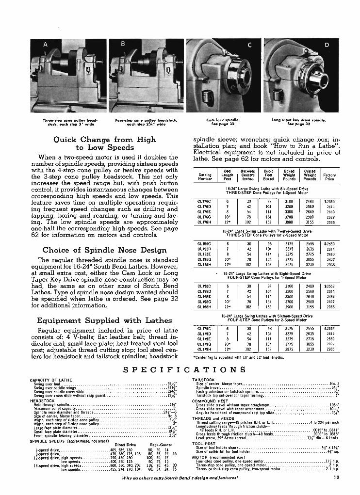
Th .... tep co'ne pulley headstock, each ltep 3' wkl.
four-step cone pulley headstock, each .tep 2!4' wide
Quick Change froIn High to Low Speeds
When a two-speed motor is used it doubles the number of spindle speeds, providing sixteen speeds with the 4-step cone pulley or twelve speeds with the 3-step cone pulley headstock. This not only increases the speed range but, with push button control, it provides instantaneous changes between corresponding high speeds and low speeds_ This feature saves time on multiple operations requiring frequent speed changes such as drilling and tapping, boring and reaming, or turning and facing. The low spindle speeds are approximately one-half the corresponding high speeds. See page 62 for information on motors and .controls.
Choice of Spindle Nose Design The regular threaded spindle nose is standard
equipment for 16-24" South Bend Lathes. However, at small extra cost, either the Cam Lock or Long Taper Key Drive spindle nose construction may be had, the same as on other sizes of South Bend Lathes. Type of spindle nose design wanted should be specified when lathe is ordered. See page 32 for additional information.
EquipInent Supplied with Lathes Regular equipment included in price of lathe
consists of: 4 V-belts; flat leather belt; thread indicator dial; small face plate; heat-treated steel tool post; adjustable thread cutting stop; tool steel centers for headstock and tailstock spindles; headstock
Cam lock .plndle. s.. poge 32
Long lapel key drive .pindle. s.. poge 32 '
spindle sleeve; wrenches; quick change box; installation plan; and book "How to Run a Lathe". Electrical equipment is not included in price of lathe. See page 62 for motors and controls.
Catalog Length Centers Feet Weight Weight Factory
'
Bed ' Between , Cubic , Boxed , Crated ,
Number Feet Inches Boxed Pounds Pounds Price
CL176C Cl176D CL176E Cl176G Cl176H
CL195C Cl195D Cl195E CL195G Cl195H
CLI9BC Cl19BD Cl19BE CL198G Cl19BH
Cl179C CL179D Cl179E CL179G Cl179H
16-24' Large Swing lathe with Six-Speed Dr;ve TH REE-STEP Cone Pulleys fOl 1-Speed Motor
6 30 98 3100 2480 ] 42 104 3200 2560' 8 54 114 3300 2640
10* 78 134 3700' 2980' 12* 102 153 3900 3155
16-24' Large Swing lathe with Tw.lve-Speed Drive ' TH REE-STEP Cone Pulleys fOl 2-Speed Motor
6 30 98 3175 2555 7 42 10'4 3275 2635 8 54 114 3375 Z715
10* 78 134 3775 30'55 12* 10'2 153 3975 3230'
16-24' large Swing lathes with Eight-Speed Drive FOUR-STEP Cono Pulleys fOl 1-Speed Motor
6 3D 98 3100 2480' 7 42 104 . 3200 2560' 8 54 114 3300 2640'
10* 78 134 3700 2980' 12* 10'2 153 3900 3155
16-24' large Swing lathe. with Sixteen-Speed Drive FOUR-STEP Cone Pulleys for 2-Speed MotOl
6 3D 98 3175 2555 7 42 10'4 3275 2635 8 54 114 3375 2715
10* 78 134 3775 30'55 12* 102 153 3975 3230'
*Center leg is supplied with, 10' and 12' bed lengths.
$2559 2614 2669 2827 2985
$ 2559-2614 2669 2827 2985
$2559 2614 2669 2827 2985
$2559 2614 2669 2827 2985
SPECIFICATIONS CAPACITY OF LATHE
Swing ov.r b.d .... .. .... . .... . . . ... ......... . . ... . ..... ..... ....... .. . 25y,J' Swing ov.r saddle wings .. ........................... . ....... . . . .. . . . . .. 24~' Swi ng over saddle cross slide ..... ...... . . ... .. . ......... . ....... . . .. . . .. 18~' Swing over cross slide without chip guard ......................... . ..... .. 19~'
HEADSTOCK Hole through spindle ...... .... .... . .. . ... . ..... . . . ..... . . . . . ....... ..... I~' Maximum collet capacily .... .. , .. . ... . . . ................... .. .... .. ....... -. [ ' Spindle nose diamet.r and thr.ads ........ . .... ... ..... . . . .. ... ........ 2~'-6 SIZe of cent.r, Morse taper ........................ ..... . . ....... . . ...... No. 3 Width, each step of 4-step cone pulley ............ . ..... .... ........ . . . .... 2~' Width, each step of 3-step cone pull.y ...... . .. . . . . . . . ...... .. . . . . ........... 3' large face plate diameter .... . .. .. ..... . .... . ..... ..... . . ......... . .. . .. 13Y.\" Small face plate diam.ter. .. .. .............. . .......... . ................. 8\1'-Front spindle bearing diameter. ...... .. .. . . .... . . . .... .. .... . .. .. ... . ... 2~"
SPINDLE SPEEDS (approximate. not exact) Direct Drive
6-sp.ed driv . ..... ... . . ...... ... .. .. . . .. 40'5, 235, 130 8-sp.ed driv . ... : .. . . . ...... .. .......... 470,280, 175, 105 '
12-speed driv., high speeds ..... ... ... . . . . 790, 460, 250 low speeds .. ...... . . . .. ... 400, 230, 125
16-speed drive, high speeds . . ... .... .. ... . 900, 550, 340, 203 , low spee.ds .•.. . . . . . .•..... 455, 274, 170, 104
Back-Geared 50, 30, 14 50, 35, 22, 15
100, 60, 27 50, 29, 15
116, 70, 45, 30 50, 34, 24, 15
TAILSTOCK Size of center, Mors. taper .... .. ... ............ .... .. ....... .. . ......... No. 3 Spindle travel .. .. .. ... . ..................... . ..... . ... . . . . . ............ 5~' Each graduation on tailstock spindle .. ... ........ . . . ... . . . . .... ....... ...... \{a" Tailstock top set-over for taper turning ........... . .............. . ......... .. 1'
COMPOUND REST Cross slide travel without taper attachment .......... , .......... . . ... .. ... . 10l<.!" Cross slide travel with taper attachment ....... , ......... ........ ...... .. . 10\{," Angular hand feed of compound rest top slide ..................... .. ....... 3~'
THREADS and FEEDS Thread cutting range-48 pitches R.H. or l.H. .... . ... . .......... 4 to 224 per inch longitudinal feeds through friction clutch-
48 feeds RH. or l.H .......... ... .............. . . . ......... . . 0015' to .0'841 ' Cross-feeds through friction clutch--48 feeds . ... ... .... ........ .. 0006' to .0315' lead screw, 29° Acme thr.ad .. ... ........ ....... , ... ........ 1~' dia.-6 thrds.
TOOL POST Size of tool holder shank ... .. ........................... ............ %" x 1%' Size of cutter bit for tool holder. .... ..... . .................... . ...... . . % ' sq.
MOTOR (recommended size) Four-step cone pulley, one-speed motor .. . ..................... . .... _ .. 1l<.! h.p. Three-step cone pulley, one-speed motor ................................. 2 h.p. Three- or fout-step cone pulley, two-speed motor ............ .. ... ...... . 2-1 h.p.
Why tW otMrs copy South Bend's tksi,n andleoturesr 13
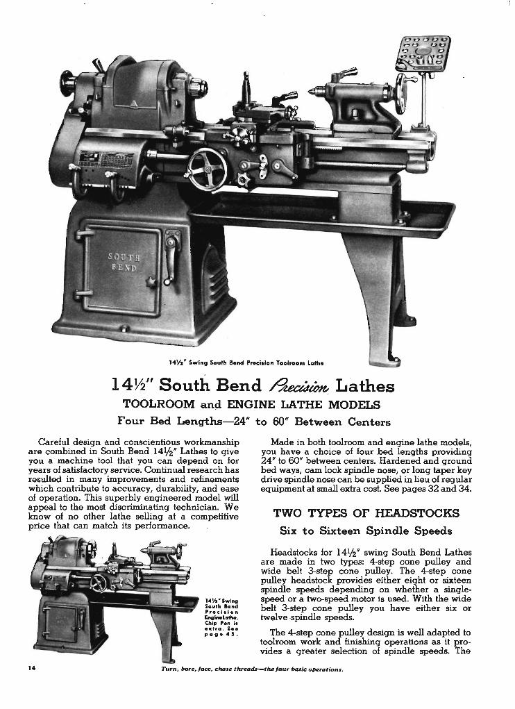
14¥z ' Swing South Bend Precision Toolroom lathe
14~" South Bend ~ Lathes \
TOOLROOM and ENGINE LATHE MODELS
Four Bed Lengths-24" to 60" Between Centers
Careful design and conscientious workmanship are combined in South Bend 141/2" Lathes to give you a machine tool that you can depend on for years of satisfactory service. Continual research has resulted in many improvements and refinements which contribute to accuracy, durability, and ease of operation. This superbly engineered model will appeal to the most discriminating technician. We know of no other lathe selling at a competitive price that can match its performance.
14Yo'Swing South Bend Precision Enginel.athe. Chip Pan i. extra . S •• page -45.
Made in both toolroom and engine lathe models, you have a choice of four bed lengths providing 24" to 60" between centers. Hardened and ground bed ways, cam lock spindle nose, or long taper key drive spindle nose can be supplied in lieu of regular equipment at small extra cost. See pages 32 and 34.
TWO TYPES OF HEADSTOCKS
Six to Sixteen Spindle Speeds
Headstocks for 141/2" swing South Bend Lathes are made in two types: 4-step cone pulley and wide belt 3-step cone pulley. The 4-step cone pulley headstock provides either eight or sixteen spindle speeds depending on whether a singlespeed or a two-speed motor is used. With the wide belt 3-step cone pulley you have either six or twelve .spindle speeds.
The 4-step cone pulley design is well adapted to toolroom work and finishing operations as it provides a greater selection of spindle speeds. The
14 Turn. bore. face. chille thrtWdl-thefour basic operations,
0'
wide belt 3-step cone pulley headstock assures maximum power transmission for heavy roughing cuts and rapid production. It is especially recommended for use with a two-speed motor.
Ouick Change from High to Low Speeds
When a two-speed motor is used it doubles the n umber of spindle speeds, providing sixteen speeds with the 4-step cone pulley or twelve speeds with the 3-step cone pulley headstock. This not only increases the speed range but, with push button control, it provides instantaneous changes between corresponding high speeds and low speeds. This feature saves time on multiple operations requiring frequent speed changes such as drilling and tapping, boring and reaming, or turning and facing. The low spindle speeds are approximately one-half the corresponding high speeds. See page 62 for information on motors and controls.
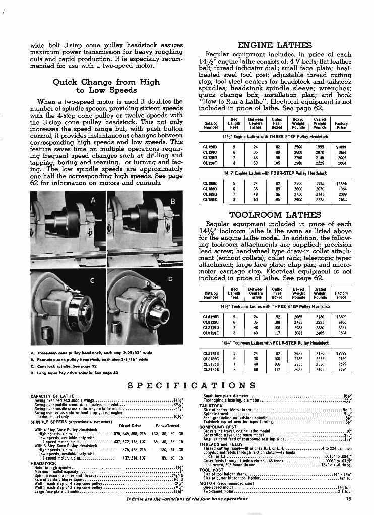
A. Th ..... Mp co ... pul .. y head.lock, eaeh.Mp 2.25/32' w ....
t. Four •• Mp eono pulloy head.locJr, eaeh.Mp 2.1/16' w ....
C. Cam lock .plnd ... $eo page 32
D. Lo"1llo_ koy drlvo .... nd ... $eo page 32
ENGINE LATHES Regular equipment included in price of each
141/2" engine lathe consists of: 4 V-belts; flat leather belt; thread indicator dial; small face plate; heattreated steel tool post; adjustable thread cutting stop; tool steel centers for headstock and tailstock spindles; headstock spindle sleeve; wrenches; quick change box; installation plan; and book "How to Run a Lathe". Electrical equipment is not included in price of lathe. See page 62.
CamJog Number
CLl298 CLl29C CL1280 CLl28E
CLl858 CLl85C CL185D CLl85E
Bed Between Cubic Boxed Crated Length Centera Feet Weight Weight Feet Inch.. Boxed Pounds Pounds
14~' Engine Lath .. with THREE·STEP Pulley H .. d8Iodc
5 24 82 2500 1995 6 36 89 2600 2070 7 48 96 2750 2145 8 60 105 2900 2225
14~' Engine Lath .. with FOUR-STEP Pulley Headetock
5 24 82 2500 1995 6 36 89 2600 2070 7 48 96 2750 2145 8 60 105 2900 2225
TOOLROOM LATHES
Factory Price
$1899 1954 2009 2064 ------
$1899 1954 2009 2064
Regular equipment included in price of each 141/2" toolroom lathe is the same as listed above for the engine lathe model. In addition, the following toolroom attachments are supplied: precision lead screw; handwheel type draw-in collet attachment {without collets}; collet rack; telescopic taper attachment; large face plate; chip pan; and micrometer carriage stop. Electrical equipment is not included in price of lathe. See page 62.
CamJog Number
CL8128B CL8129C CL8128D CL8128E
CL81858 CL8185C CL8185D CL8185E
Bed Between Cubic Boxed c.ated Length Centera Feet Weight Weight
Feet Inch.. Boxed Pound. Pounds
14~' Toolroom Lath .. with THREE-STEP Pulley Headstock
5 24 92 2685 2180 6 36 100 2785 2255 7 48 ' 106 2935 2330 8 60 117 3085 · 2405
14~' Toolroom Lath .. with FOUR-STEP Pulley Headetock
5 24 92 2685 2180 6 36 100 2785 2255 7 48 106 2935 2330 8 60 117 3085 2405
Factory Price
$2399 2460 2522 2584
$2399 2460 2522 2584
SPECIFICATIONS CAPACITY OF LATHE
Swing over bed and saddle wines . . .... . . ... .. . ..•......... . .. .. . . ... . . . . 14%' Swing over saddle cross slide, toolroom modeL .... . ... ... ........... . . . .. 81\16' Swing over saddle cross slide, enJine lathe model. .. . .. . . . . ... ............. 8~· Swing over cross slide without chIp guard, engine
lathe model only ................. . ......... . .. ... . . ............. . . . . 10~·
SPINDLE SPEEDS (approximate, not exact)
Small face f,1.te di.amet~r .. . ........ ... .. ....... .............. ... ..... .. 8~· Front spond e beanng, dl.meter .. ..... .... . ............. . ................ 2%'
TAILSTOCK Sil.e of center, Morse taper .. .. .. . . ... : ... . ...... .. ........ .. . . . .. ....... No.3 SpIndle traveL .. . ... : . ...... : ......... . . ........ ......... .... ..... ..... 5~· Each. gradu.toon on ta"stock spondle: .... . . . ... . . . . . ......... .. ....... . . . .. ~.
Direct Drive Back-Geared Tallstock top set·over for taper turning .. ............................... ... 1\16' With 4.Step Cone Pulley Headstock COMPOUND REST .
High speeds, r.p.m .... . ................. 875, 545, 350, 215 130 80 50 30 gross shde tr.vel, en~one lathe modeL ... . ................................. 10' low speeds, available only with ' , , ross shde travel, too room modeL .. ..................................... , 9~'
2.speed motor, r.p.m ... .. . . . .. ... ..... 437, 272, 175, 107 65, 40 25, 15 Angular hand feed of compound rest top slode ........... ............ . . . . . . . 3~· With 3.Step Cone Pulley Headstock ' TH READS and FEEDS
High speeds, r.p.m..... .. .... . . . ........ 875, 428, 215 130 61 30 Thread cutting range--48 pitches R.H. or L.H ............ . .... ... 4 to 224 per inch low speeds, available only with ' , lon~tudinal feeds through friction clutch-48 feeds
2.speed motor, r.p.m...... .. .......... 437, 214.107 65 30 15 R .. or L.H ... : ..................................... ; .. ... .0015' to 0841' HEADSTOCK ' , Cross·feeds through friction clutch-48 feeds .............. .... . . . 0006' to :0315'
Hole through spindle .................................................... 1~' lead screw, 29° Acme thread . ... .................... .. . . . . . . . 1 ~· di'.·6 thrds. Maximum collet cap.city .. ... ... .......................................... ·.1· T~OL POST Spindle nose diameter and threads ...................................... 2~·.6 Sile of tool holder shank ... ............ .. ... ... . ......... ; ... .. . ... %' • 1~' SI~e of center, Morse taper .............................................. No. 3 Ile of cutter bIt for tool holder ..... . . . ........... . .................... ~. sq. W!dth, each step of 4·step cone. pulley ............. .. ........ . ........... . 2~· MOTOR (recommended .ze) WIdth, each step of 3·step cone pulley .............. . ..... .. .... . ......... 2",f' One-speed motor .. ...... ... ..... .. ... ... . . ... . . . ... . ... . .. . . . ... . . . . 1~ h.p Large face plate dl.meter .... . ........ .. . . . ........ .. ..... . . ............ 13~· Two·speed motor ................... . ...... ... ...... . ..... .. .. . ...... 2.f h.p:
Inj/nite are the _riDtioru 0/ the/our basic operatioru. 15
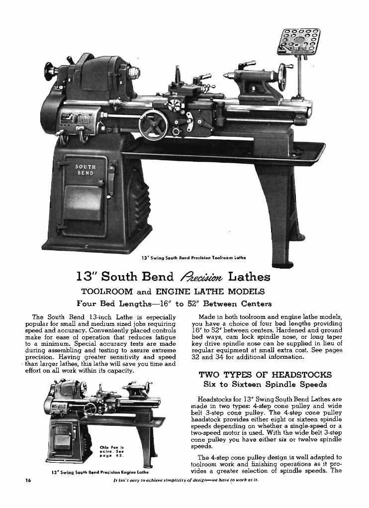
13 " Swing South Bend Precision Toolroom lathe
13" South Bend ~ Lathes TOOLROOM and ENGINE LATHE MODELS
Four Bed Lengths-16" to 52" Between Centers
The South Bend 13-inch Lathe is especially popular for small and medium sized jobs requiring speed and accuracy. Conveniently placed controls make for ease of operation that reduces fatigue to a minimum. Special accuracy tests are made during assembling and testing. to assure extreme precision. Having greater sensitivity and speed
. than larger lathes, this lathe will save you time and effort on all work within its capacity.
Chip Pan I, extra . Se. page 45 .
13" Swing South Bend Precision Engine Lathe
Made in both toolroom and engine lathe models, you have a choice of four bed lengths providing 16" to 52" between centers. Hardened and ground bed ways, cam lock spindle nose, or long taper key drive spindle nose can be supplied in lieu of regular equipment at small extra cost. See pages 32 and 34 for additional information .
TWO TYPES OF HEADSTOCKS Six to Sixteen Spindle Speeds
Headstocks for 13" Swing South Bend Lathes are made in two types: 4-st-ep cone pulley and wide belt 3-step cone pulley. The 4-step cone pulley headstock provides either eight or sixteen spindle speeds depending on whether a single-speed or a two-speed motor is used. With the wide belt 3-step cone pulley you have either six or twelve spindle speeds. .
The 4-step cone pulley design is well adapted to toolroom work and finishing operations as it provides a greater selection of spindle speeds. The
16 It isn'teo,y to achieve ,implicityof design-we have !o work at it ,
wide belt 3-step cone pulley headstock assures maximum power transmission for heavy roughing cuts and rapid production. It is especially recommended for use with a two-speed motor.
Quick Change froIT\ High to Low Speeds
When a two-speed motor is used it doubles the number of spindle speeds, providing sixteen speeds with the 4-step cone pulley or twelve speeds with the 3-step cone pulley headstock. This not only increases the speed range but, with push button control, it provides instantaneous changes between corresponding high speeds and low speeds. This feature saves time on multiple operations requiring frequent speed changes such as drilling and tapping, boring and reaming, or, turning and facing. The low spindle speeds are approximately one-half the corresponding high speeds. See page 62 for information on motors and controls.
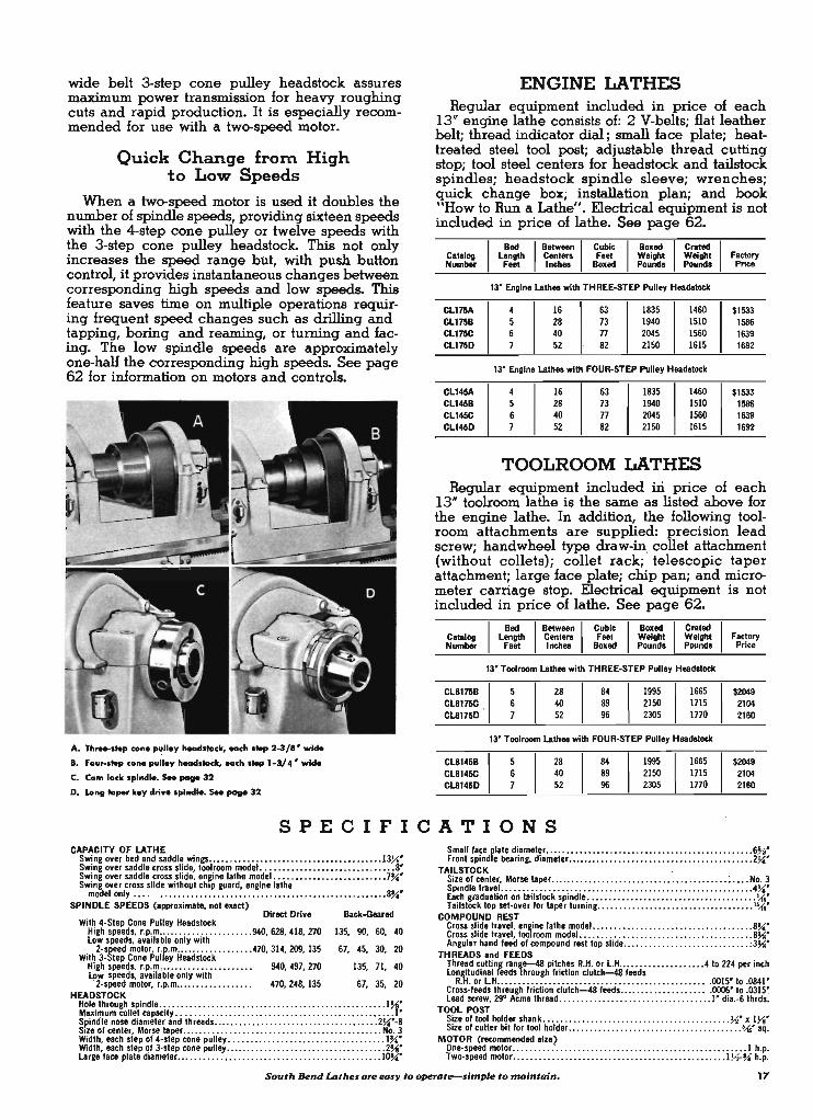
A. Th .... ltep co ... pulley 1Macl11ock, each ltep 2-3/" wide
I . Four-I .... co ... pulley 1Macl11ock, each I .... 1-3/ 4' wide C. Cam lock splnelle. See _ 32
D. Long 10 .... key drive splnelle. See _ 32
ENGINE LATHES Regular equipment included in price of each
13" engine lathe consists of: 2 V-belts; flat leather belt; thread indicator dial; small face plate; heattreated steel tool post; adjustable thread cutting stop; tool steel centers for headstock and tailstock spindles; headstock spindle sleeve; wrenches; quick change box; installation plan; and book "How to Run a Lathe". Electrical equipment is not included in price of lathe. See page 62.
Catalog I L:"~ I ~:;.= I c;'~tC I ~:~ I ~':i= Factory Number Feet Inches Boxed Pounds Pounds Price
13' Engine Lath .. with THREE-STEP Pulley Headstock
CL175A 4 16 63 1835 1460 $1533 CLl758 5 28 73 1940 1510 1586 CLl75C 6 40 77 2045 1560 1639 CL175D 7 52 82 2150 1615 1692
13' Engine Lathes with FOUR-STEP Pulley Headstock
CL145A 4 16 63 1835 1460 $1533 CL1458 5 28 73 1940 1510 1586 CLl45C 6 40 77 2045 1560 1639 CL145D 7 52 82 2150 1615 1692
TOOLROOM LATHES Regular equipment included iri price of each
13" toolroom lathe is the same as listed above for the engine lathe. In addition, the following toolroom attachments are supplied: precision lead screw; handwheel type draw-in, collet attachment (without collets); collet rack; telescopic taper attachment; large face plate; chip pan; and micrometer carriage stop. Electrical equipment is not included in price of lathe. See page 62.
Catalog I L:,e;,. I ~e:= I ~~~ I ~:~ Weight Factory Crated I Number Feet Inches Boxed Pounds Pounds Price
13' Toolroom Lathes with THREE-STEP Pulley Headstock
CL81758 I 5 Cl8175C , 6 Cl8175D 7
28 40 52
= I ir~ I !~~ 96 2305 1770
13' Toolroom Lathes with FOUR-STEP Pulley Headstock
Cl81458 Cl8145C Cl8145D
5 6 7
28 40 52
84 89 96
1995 2150 2305
1665 I 1715 1770
$2049 2104 2160
$2049 2104 2160
SPECIFICATIONS CAPACITY OF LATHE
Swing oyer bed and saddle wings ••. . ..• . . . • . . • .•• . •.• . . .•• .• ••... •. . ...• 13J.i' Swing over saddle cross slide, tool room model ............... .... .. ... ..... .. 8' Swing over saddle cross slide. enBine lathe model .... .... .... .. .. .... .... .. 7~' Swing over cross slide without chIp guard, engine lathe
model only .... .. ... .. .. ..... .. .. .. .. . . . ...... .. .. .. .... .... . ... .. ... 8~·
SPINDLE SPEEDS (approximate, not exact) Direct Drive
With 4-Step Cone Pulley Headstock High speeds, r.p.m ........ : .. ........ ... 940, 628, 418, 270 Low speeds, available only with
2-speed motor, r.p.m ..... .... ......... 470, 314, 209, 135 With 3-Step Cone Pulley Headstock
I!igh speeds, r.P.m,.. .... ...... ........ . 940, 497, 270 Low speeds, available only with . 2-speed motor, r.p.m...... .. .. .. .. .. .. 470, 248, 135
HEADSTOCK
Back-Geared
135, 90, 50, 40
67, 45, 30, 20
135, 71, 40
67, 35, 20
Hole through spindle .................................... .. ...... .. .. .. .. 1~· Maximum collet capacity .......... . ......... . .................... . ....... '.f · Spindle nose diameter and threads .. .. ....... .. ...... .. ...... .. .... .. ... 2~·-8 S,ze of center, Morse taper ..... .. ........................... .... .. . ..... No. 3 Width, each step of 4-step cone pulley . .. ................................ . 1 ~' Width, each step of 3-step cone pulley ....... . . . . . . . . ............ . .. . . . .... 2~· Large face plate diameter .. .. .. . ...... .. .. .... .. .... .... ............. .... 10~·
Small face plate diameter ................ . .................. .. ........... 6%' Front spindle bearing. diameter .... .... .... ...... .. ............ .. ..... .... 2~·
TAILSTOCK ' Size of center, Morse taper .. .......... . .. .... .... .. ...... .. ........ ; .... No. 3 Spindle travel. •.• . .. . ..... . . •. .. •...... .. ..•. . .. . . . . . ..•.. . . . ..•.•.• . . . 4~· Each graduation on tailstock spindle ...................................... .'1iO· Tailstock top set-over for taper turning .......... ...... ...... .. ..... .. ..... I~·
COMPOUND REST Cross slide travel, engine lathe model ..................................... 8~· Cross slide travel, toolroom modeL . .. .... . ............ . .................. 8J.i· Angular hand feed of compound rest top slide .... . ......... .. .... .. ....... :3J.i·
THREADS and FEEDS Thread culling range--48 pitches R.H. or LH ...... . ..... . ..... . . 4 to 224 per incn
Lo~~~u:;n~~~~~~ .t~~~~~~. ~r~~i~~. ~1.U.t~~. f~.S. . . . . . . . . . . . • . ,OOl5' to .0841' Cross-feeds thr.ugh friction clutch-48 feeds .............. . ...... 0006' to .0315~ Lead screw, 29" Acme thread ...................... .. ........... 1' dia.-6 thrds.
TOOL POST Size of tool holder shank ..... .... .. .. ...... .... ............ .... .... )4' x 1J.i· Size of cutter bit for tool holder ........ . ........................... . ... ~' sq.
MOTOR (recommended si •• ) One-speed motor ... .... ............. . ................................. 1 h.p. Two-speed motor .. . .......... .. .... . . . ..... .. ........... .. ..... .. lYr~ h.p.
South Bend LDtlles are easy to operot_s/mple to mointain. 17
10' Swing South Bend Precision Toolroom Floor Lathe
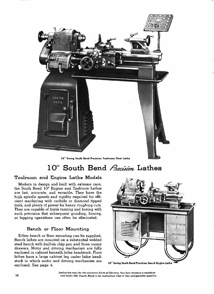
10" South Bend ~ Lathes Toolroom and Engine Lathe Models
Modern in design and built with extreme care, the South Bend 10" Engine and Toolroom Lathes are fast, accurate, and versatile. They have the high spindle speeds and rigidity required for effi-
. cient machining with carbide or diamond tipped tools, and plenty of power for heavy roughing cuts. They are capable of finish turning' and boring with such precision that subsequent grinding, honing, or lapping operations can often be eliminated.
Bench or Floor Mounting
Either bench or floor mounting can be supplied. Bench lathes are mounted on a substantial welded steel bench with built-in chip pan and three roomy drawers. Motor and · driving mechanism are fully enclosed in cabinet beneath lathe headstock. Floor lathes have a large cabinet leg under lathe headstock in which motor and driving mechanism are enclosed. See page 4.
10 ' Swing South Bend Precisian Bench Engine Lathe
18 Imitation may Ix! the sincerest form of flattery. but JUlt Ix!caule a machine
tool looks like South Bend il no indication that it hal comparable quality.
+
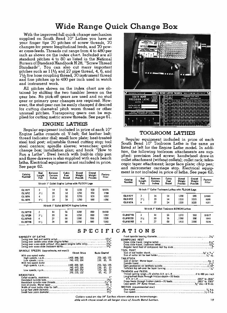
Wide Range Quick Change Box With the improved full quick change mechanism
supplied on South Bend 10" Lathes you have at your finger tips 70 pitches of screw threads, 70 changes for power longitudinal feeds; and 70 power cross-feeds. Threads cut range from 4 to 480 per inch as shown on the index chart. Included are all standard pitches 4 to 80 as listed in the National Bureau of Standard Handbook H 28, "Screw Thread Standards". You can also cut many important pitches such as 11112 and 27 pipe thread, 4, 6, and 7112 fire hose coupling thieaci,. 30 instrument thread and fine pitches up to 480 per inch used in watch and instrument work.
All pitches shown on the index chart are obtained by shifting the two tumbler levers on the gear box. No pick-off gears are used and no stud gear or primary gear changes are required. However, the stud gear can be easily changed if desired for cutting diametral pitch worm thread or other . unusual pitches. Transposing gears can be supplied for cutting metric screw threads. See page 61.
ENGINE LATHES Regular equipment included in price of each 10"
Engine Lathe consists of: V-belt; flat leather belt; thread indicator dial; small face plate; heat-treated steel tool post; adjustable thread cutting stop; tool steel centers; spindle sleeve; wrenches; quick change box; installation plan; and book "How to Run a Lathe". Steel bench with built-in chip pan and three drawers is also supplied with each bench lathe. Electrical equipment is not included in price. See page 62.
ala og Length Centers Feet Weight Weight Factory C I Bed-1 Between-l-cubIC Bo.ed Crated
Number Foot Inchea Bo.ed Pounds Pounds Price
lD-inch I ' Collet Engine Lathe. with FLOOR Legs
CL187Y 3 14 50 1230 930 $1174 C1187Z 3J~ 20 50 1250 950 1198 CL187A 4 27 50 1270 970 1222 C1187R 41'2 34 54 1290 990 1256
----_. - ------- -_ .-
lD-inch I ' Collet BENCH Engine Lathes
CL187YB 14 56 1200 850 $1268 CL187ZB 3'2 20 56 1250 880 1292 C1187AB 4 27 68 1300 .950 1329 CL187RB 4V. 34 68 1350 . 980 1363
SOUTH BENO (E PRECI:~~.~ ;ATHE g)
C A TA LOG N O __ B ED LE N GT H __
C .. .. "'T .. ::>
STOP "o'I ACH N ( 8(rOI'lE S H IrTING TU llA BLER lE .... ERS
• C [ B 0 f G
m'"
TOOLROOM LATHES Regular equipment included in price of each
South Bend 10" Toolroom Lathe is the same as listed at left for the Engine Lathe model. In addition, the following toolroom attachments are sup.plied: precision lead screw; handwheel draw-in collet attachment (without collets); collet rack; telescopic taper attachment; large face plate; chip pan; and micrometer carriage stop. Electrical equipment is not included in price of lathe. See page 62.
Catalog Number
CL81B7Y C18187Z C18187A
C18187YB CL8187ZB C18187AB
Bed Between 1- Cubit 1 Bo.ed -I c;:';t~ 1 Factory Lentth Centers Foet Weight Weight Price
Feet Inches Bo.ed Pounds Pounds
lD-inch I ' Collet Toolroom Lathes with FLOOR Leg.
14 54 1290 990 $1560 3'4 20 54 1310 1010 1586 4 27 54 1330 1030 1611
lD-inch I' Collet Toolroom BENCH Lathes
3 14 56 1310 960 S1617 3)1 20 56 1360 990 1641 4 27 68 1410 1060 1678
S P 'E elF I CA T I O N S CAPACITY OF LATHE
Swing over bed .nd saddle wings ...... . .......... . ...................... 10~' Swing over s.ddle cross slide (.n~ine I.the) ............. .. ............... .. 5}i' Swing over cross slide without chIp gu.rd (engine I.the only) ......... . ...... 6~· Swing over cross slide (toolroom I.the) .. ... ....... . ............... . ....... 5~'
Front spindle be. ring diameter. .......... . ....... . ........ . ............ . . . 2)4' COMPOUND REST
Cross slide travel, (engine lathe) ... .. ........ .. ..... . ................ . .... 6)4' Cross slide travel , (toolroom lathe) ...................................... .. 531' Angular hand feed of compound rest top slide .. .................... . .... ..... 2'
SPINDLE SPEEDS (approximate, not exact) Direct Drive Back·Geared
With one-speed motor High speeds, r.p.m .... .. ........ , ...... 1400. 898. 585 250, 160, 105 Low speeds. r.p.m ........ ...... .. ..... 740. 470, 304 130, 85, 55
With two· speed motor High speeds, r.p.m ..................... 1400, 898, 585 250, 160, 105
740, 470, 304 130, 85, 55 Low speeds, r.p.m ..................... 700, 449, 292 125, 80, 52
370, 235, 152 65, 42, 27 HEADSTOCK
Collet cap.city, ma.imum ...... . ................ . ........... . ........ ... ... 1' He.dstock spIndle hole .. ... . ......... . ........ . ......................... 1~' Headstock spindle nose thre.ds .................... . ...... ... ... .... .... 2)4'·8 Size of center, Morse t.per. .... .................. .. .................. . .. No. 2 Width of cone pulley step for belt ............ ............................ .. 1'",' L.rge f.ce pl.te diameter. .. .. ........................... . ......... . .. ... 8~' Sm. II f.ce pl.te di.meter. .... . ........... . ................ .... ..... ... . . 5~'
TOOL POST Size of tool holder shank ....... ........... ............... . ......... ~' x '''16' Size of cutter bit for tool holder .. ..... ................. .... ............ )4' sq .
TAILSTOCK Size of center, Morse taper ....... . ............ . ......... . ............... No. 2 Spindle tr.vel. ......................................... . ............... 2~' E.ch gradu.tion on t.ilstock spindle .. . ............. . .... . . . .. ... . . . ..... 1/ 10' Tailstock top set·over for taper turning .... ...... . .. ..... . . .. ........ ... . . . '\1;0'
THREADS and FEEDS Thre.d cutt ing r.nge-70 pitches R.H. or L.H ..... . . . .. ....... ... 4 to 480 per inch Longitudinal feeds through friction clutch-70 feeds '
R.H. or L.H. .. ..................................... ......... 0007' to .0836' Cross-feeds through friction clutch-70 feeds .. ... .. ............. 0003' to .0303' Le.d screw, 29" Acme thre.d .................. .. .... ......... ~' di • . -8 thrds
MOTOR (recommended size)
~~~~~~::~:::::: :::::: :'.:: ::'.:: :'.:::::::::::::::::::::: :'.:: :: ::::::df ~t Collets used on the 10' Lathes shown obove are interchange
able with those used on all larger sizes of South Bend Lat1u!s. 19
20
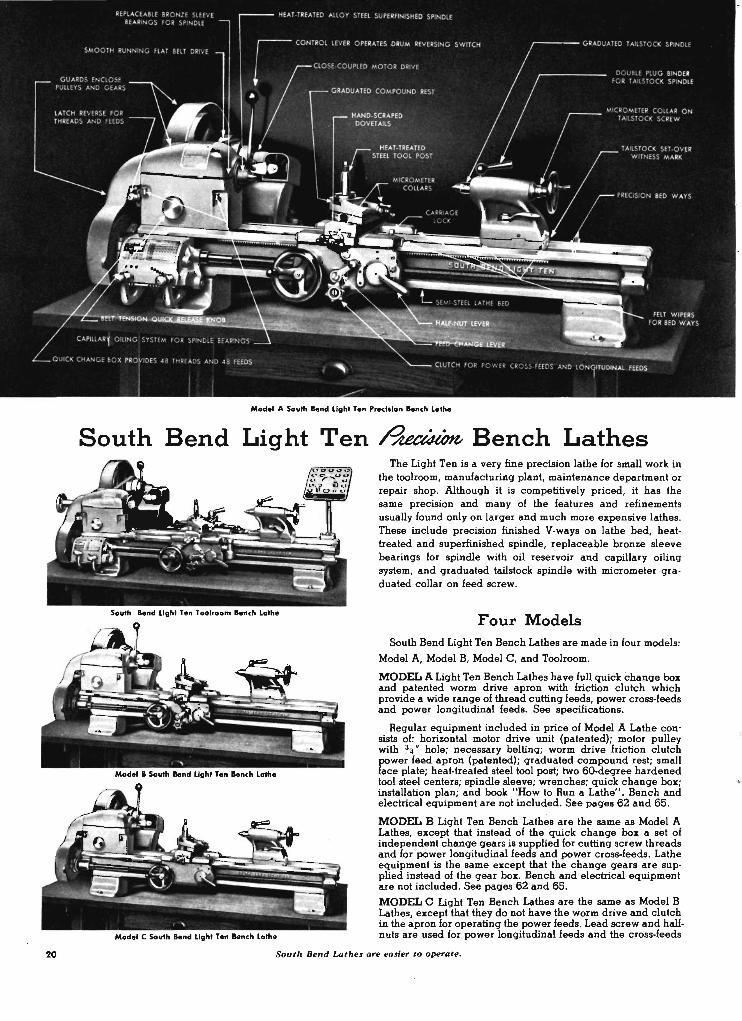
Model A South lend Light Ten ,.,.cliion lench lothe
South Bend Light Ten ~ Bench Lathes
Model C South lend light Te n Bench lathe
The Light Ten is a very fine precision lathe for small work in the toolroom, manufacturing plant, maintenance department or repair shop. Although 'it is competitively priced, it has the same precision and many of the features and refinements usually found only on larger and much more expensive lathes. These include precision finished V-ways on lathe bed, heattreated and superfinished spindle, replaceable bronze sleeve bearings for spindle with oil reservoir and capillary oiling system, and graduated tailstock spindle with micrometer graduated collar on feed screw.
Four Models South Bend Light Ten Bench Lathes are made in four models:
Model A, Model B, Model C, and Toolroom.
MODEL A Light Ten Bench Lathes have full quick change box and patented worm drive apron with friction clutch which provide a wide range of thread cutting feeds, power cross·feeds and power longitudinal feeds. See specifications.
Regular equipment included in price of Model A Lathe consists of: horizontal motor drive unit (patented); motor pulley with %'" hole; necessary belting; worm drive friction clutch power feed apron (patented); graduated compound rest; small face plate; heat-treated steel tool post; two 50-degree hardened tool steel centers; spindle sleeve; wrenches; quick change box; installation plan; and book "How to Run a Lathe". Bench and electrical equipment are not included. See pages 62 and 65.
MODEL B Light Ten Bench Lath~s are the same as Model A Lathes, except that instead of the quick change box a set of independent change gears is supplied for cutting screw threads and for power longitudinal feeds and power cross-feeds. Lathe equipment is the same except that the change gears are supplied instead of the gear box. Bench and electrical equipment are not included. See pages 62 and 65.
MODEL C Light Ten Bench Lathes are the same as Model B Lathes, except that they do not have the worm drive and clutch in the apron for operating the power feeds. Lead screw and halfnuts are used for power longitudinal feeds and the cross-feeds
Sout1. Bend Lat hes are easier to operate.

A. Interior of Quick Cha nge 10" far M ...... A and Toolroom Lath" D. Chang. Gean Suppl .... far M ....... 1 a nd C
I. P .... n .... Apron u .... an Toolroom, Mod.1 A a nd M ...... 1 Lathe. E. Apron . uppl .... on Model C Lath.
C. Palen .... Twelv .... PHd Flal IeII HorlEonlal Molar Drive F. Palen .... SI_n·.PHd V· .... , Horlzonlal Molar Drive
are hand-operated. Otherwise. the equipment is the same. Bench and electrical equipment are not included. See paqes 62 and 65.
TWO TYPES OF DRIVES Twelve or S ixteen Spindle Speeds
TOOLROOM Liqht Ten Bench Lathes are the same as Model A Lathes, and have the same reqular equipment. In addition, the followinq toolroom attachments are supplied: precision lead screw; handwheel type draw·in collet attachment (with· out collets); collet rack; plain taper attachment; thread indica· tor; thread cuttinq stop; larqe face plate; and micrometer carriaqe stop. Bench and electrical equipment are not included. See paqes 62 and 65.
All models of Liqht Ten Horizontal Motor Drive Bench Lathes can be supplied with either flat belt or V·belt cone pulleys for the headstock. The flat belt drive provides twelve spindle speeds. Power is transmitted with extreme smoothness at all speeds makinq this drive popular with those who require hiqh precision and a fine finish. The sixteen·speed V·belt drive is well adapted to production work, especially for heavy rouqhinq cuts at slow speeds. To replace the endless V·belt, it is neces· sary to disassemble both the lathe headstock and the drive unit.
Light T en South Bend Bench Lathes
Bed Between Model Length Centora
foet lnell ..
3 16 Toolroom 3Y.; 22
4 28
3 16
Model A 31-j/ 22 4 28 4Y.; 34
3 16 3Y.; 22
Model B 4 28 41 -2 34
3 16
Model C 3Y.; 22 4 28 41 <5 34
CAPACITY Of LATHE Swing over bed, maximum ... . . . . ...... .... ..... 10' Swing over saddle wings .. ...•................ 91~' Swing over cross .Iide, (model. A, B, C) .•• . ..... 6)4' Swing over cross .Iide, (toolroom lathe) . •..•.. . .. 5}i'
TAILSTOCK Size of center,. Morse taper •••••. . ......... ... . No. 2 Spindle travel.. .... • . ............... . .•. •. ... 2}i' Each graduation on tail.tock .pindle . .. •...••...•• '10' Tailstock top set-over for taper turning .. . .• •.•. . . %'
COMPOUND REST Cross .Iide t ravel (model. A, B, C) .............. 5}i' Cross slide travel (tool room lathe) ....... ...... . . 5% ' Angular hand feed of compound re.t top .Iide .... 2)4'
TOOL POST Size of tool holder shan k . . ....•. ...... •.. %' x 'l{.' Size of cutter bit for tool holder ... ... ...•.. . . )4' sq.
Cubic Boxed Crated With l&-Speed V-Belt With 12-Speed Flat Bell feet Weight Weight Horizontal Motor Drive Horizontal Motor DrlVI Boxed Pouncia Pounds Cat. No.
26 6SO 520 CU770Y
26 665 535 CU770Z
29 690 5SO CU770A
22 600 490 CL770Y 22 615 S05 CL770Z 25 640 520 CL770A 29 670 535 CL770 R
22 585 475 CL767Y
22 600 490 CL781Z 25 625 505 CL787A 29 655 520 CL767R
22 575 465 CL753Y 22 590 480 CL753Z 25 615 495 CL753A 29 645 510 CL753R
S PEC I FICATIONS SP INDLE SPEEDS (approximale, not exact)
Direct Drive Back·Gear", With Flat Belt
High, r.p.m. 1435, 844, 502 276, 165, 96 Low, r.p.m. 706, 415, 244 137, 80, 48
With V-belt High, r.p.m. 1365, 1010, 760, 570 265, 195, ISO, 112 Low, r.p.m. 670, 495, 370, 285 130, 95, 75, 52
HEADSTOCK Hole through .pindle . .. . ... .. . ............. . . . "'~' Maximum collet cap.city ••........... . . . . . ...... % ' Spindle nose diameter and thread. per inch . . . 1y';'-8 SIZe of center, Morse taper. •. .. ...... , .. . ..... No.2 Width of cone pulley step for flat belt. .••. . •. ..... 1' Small face plate diameter. ... ••• .. . ..• . . . . . . ... 5~' Front .pindle bearing diameter. •. . .. ....... ... 1 lI",'
South Bend Lathe. a re simpler to maintain.
Price Cat. No.
$746.00 CU670Y 768.00 CL8670Z 789.00 CU670A
515.00 CU70Y 537.00 CU70Z 558.00 CU70A 589.00 C1670R
439.00 CL861Y 461.00 CL867Z 481.00 CL867A 512.00 CL867R
369.00 CL653Y 390.00 CL653Z 411 .00 CL653A 441 .00 CL653R
THREAD CUTTING RANGE Toolroom and Model A--48 pitch e.,
Price
$731.00 753.00 774.00
500.00 522.00 543.00 574.00
424.00 446.00 466.00 497.00
354.00 375.00 396.00 . 426.00
R.H. or L.H .•. .. . . ............... 4 to 224 per inch Model. B .nd C--45 pitches, .
R.H. or L.H .......... ... .... . ... . 4 to 160 per inch Lead screw, 29° Acme thre.d ...... • ~' d ia .~ thrd • .
POWER LONGITUDI NAL fEEDS Toolroom and Model A--48 feed • ••... 0015' to .0853' . Model B-26 feed • ... .. ... . . ........ 0021' to .0155' Model C-14 feed •. .... . . . . . ... . • . •. 0021' to .0156'
POWER CROSS· f EEDS Toolroom and Model A--48 feed • . . ... 0004' to .0255' Model 8-23 feeds . . . . . . . . . . . . • . . .. .0009' to .0046'
MOTOR Standard .ize of motor recommended • . •. . . . .. H h.p.
21
South Bend Light Ten
.~ Floor Lathes
with Metal Column Base
Underneath Motor Drive
Sovth ...... light T ... PNdsion Tool ..... lathe with MeN! Column Ia ..
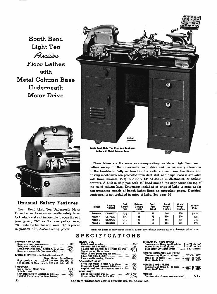
These lathes are the same as correspondinq models of Liqht Ten Bench Lathes, except for the underneath motor drive and the necessary alterations in the headstock. Fully enclosed in the metal column base, the motor and drivinq mechanism are protected from dust, dirt, and chips. Base is available with three drawers, lO~" x 571" x 14" as shown in illustration, or without drawers. A built-in chip pan with %" head around the edqe forms the top of the metal column base. Equipment included in price of lathe is same as for correspondinq models of bench lathes listed on precedinq paqes. Electrical equipment is not included in price of lathe. See paqe 62.
Unusual Safety Features South Bend Liqht Ten Underneath Motor
Drive Lathes have an automatic safety interlock which makes it impossible to open the end qear quard, "A", or the cone pulley cover, "B", until the belt tension lever, "L" is placed in position "R", disconnectinq power.
Calalog Bed BMween CubIc Bo .... Cral'" Faclory Modil NUMber Length Canl ... Feet Weighl Weighl Price Feet Inch .. ·Bo .... Peundo Pound.
Toolroom Cl..8370ZD 3)1 22 52 940 750 $1052 Model A CU70ZD 3)1 22 52 910 720 821 Model 8 Cl387ZD 3)1 22 52 895 705 744 ModeiC Cl353ZD 3).2 22 52 885 695 675
NOlo: For prices of above lathes on metal column base wilhout drawers deduct $35.00 from prices shown.
SP Eel F I CAT ION S CAPACITY OF LATHE HEADSTOCK
Swine ovor bed, maximum ... . . . ... . . .. . . . .. .... 10' Hole tbrouch spindle .. ... ..•...••.•.•........ . n~· Swine over saddle wines ... ........ ........... 91~· Maximum collet capacity ........................ ",. Swine over cross slide, (models A. B, C) .. : .... .. 6}i· Spindle nose dilmeter Ind thr .. ds per inch .. .. 1)1··g Swine over cross slid. (toolroom .. the) ........ .. 5~· Size of center, Morse t.per .. .. ................ No. 2
SPINDLE SPEEDS (appro.lmale, nolOllel) Width of con. pull.y st.p for bell .. .. ............. 1' Small 1_ Dllt. di.meter ...................... 5~·
Direcl Drive Back-Geer... Front Spindle belrinc. di.meter ...... . ........... ~. Hich speeds, r.p.m .. .... 1365, 780, 460 265, ISS, 90 COMPOUND REST Low ~s, r.p.m . ..• .. 715, 410, 240 135, 78, 50 Cross slide tr.weI (models A, B, C) ....... . . .•..• 5~·
TAILSTOCK Cross slid. travel (toolroom I.the) .......... . . .. . 5~· Siz. of cenler, Morse I. per ••• . ... •.... •. ... ... No. 2 An,""r h.nd feed of compound rest lop slide •• . . 2}i·
THREAD CUTTING RANGE Toolroom .nd Model A-48 pitebes .. 410 224 per inch Models B .nd C-45 pitches •... .... 4 to 160 per inch L .. d screw, 29" Acm.thr .. d ....... ~' dil.-8thrds.
POWER LONGITUDINAL FEEDS . Toolroom .nd Model A-48 feeds ...•. 0015' to .0853' Mod.1 8-26 leeds .. .. .. ............ 0021' to .0155' Model C-14feeds................ . .0021' 10 .0156'
POWER CROSS-FEEDS Toolroom .nd Model A-48 feeds . • ... 0004" to .0255' Model 8-23 feeds.... .. .. .. .. .. ... .0009' to .0046'
Spindle Iravel ............... ...... ........... 2~· TOOL POST Eech cradultion on lIilsiock spindl ............ .. t,(,' Size of tool holder shank .......... . ...... ~. x "Ai' MOTOR T.ilslock top sel-over for t.per lurnine ........... ~. Size of cutt.r bil for 1001 hold.r ............ .. }i' sq. Standard size of motor recommended ....... ... )1 h.p.
22 TM molt faithful COP)! connot perf«tl)! motch the ori,lnal.
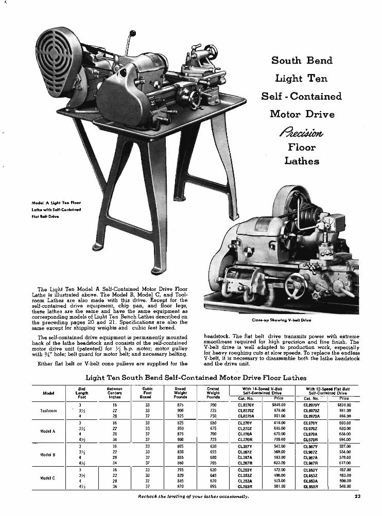
Model A Light Ten Floor
Lathe with Self-Contained
Ficol Belt Drive
The Light Ten Model A Self-Contained Motor Drive Floor Lathe is illustrated above. The Model B, Model C, and Toolroom Lathes are also made with this drive. Except for the self-contained drive equipment, chip pan, and floor legs, these lathes are the same and have the same equipment as corresponding models of Light Ten Bench Lathes described on the preceding pages 20 and 21. Specifications are also the same except for shipping weights and cubic feet boxed.
The self-contained drive equipment is permanently mounted back of the lathe headstock and consists of the self-contained motor drive unit (patented) for ~ h.p. motor; motor pulley with %" hole; belt guard for motor belt; and necessary belting.
Either flat belt or V-belt cone pulleys are supplied for the
South Bend
Light Ten
Self - Contained
Motor Drive
~ Floor
Lathes
Clooe-up Showing V-belt Drive
headstock. The flat belt drive transmits power with extreme smoothness required for high precision and fine finish. The V-belt drive is well adapted to production work, especially for heavy roughing cuts at slow speeds. To replace the endless V-belt, it is necessary to disassemble both the lathe headstock and the drive Unit.
Light Ten South Bend Self-Contained Motor Drive Floor Lathes
Bed Between Cubic Boxed Crated With IS-Speed V-IIelt With 12-Speed Flat Belt Model Length Centen Feet Weight Weight Self-Contained Drive Self-Contained Drive
Feet Inches Boxed Pounds Pounds Cat. No. 15"c8 Cat. No. P,ice
3 16 33 875 700 Cl8270Y $849.00 CL8970Y $834.00 Toolroom 3~ 22 33 900 725 CL8270Z 876.00 CL8970Z 881.00
4 28 37 ·925 750 CL8270A 901.00 CL8970A 886.00
3 16 33 825 650 CL270Y 618.00 CL970Y 603.00
Model A 3~ 22 33 850 675 Cl270Z 845.00 CL970Z 630.00 4 28 37 875 700 Cl270A 670.00 C1970A 655.00 4~ 34 37 900 725 CL270R 709.00 CL970R 694.00
3 16 33 805 630 C1267Y 542.00 CL987Y 527.00
Model B 3~ 22 33 830 655 Cl267Z 569.00 CL987Z 554.00 4 28 37 855 680 1:1267A 593.00 CL987A 578.00 4~ 34 37 890 705 C1267R 632.00 CL987R 617.00
3 16 33 795 620 CL253Y 472.00 CL953Y 457.00
Model C 3~ 22 33 820 645 Cl253Z 498.00 CL953Z 463.00 4 28 37 845 670 Cl253A 523.00 CL953A 508.00 4~ 34 37 870 695 Cl253R 561.00 CL953R 546.00
Recheck the le"eling oj you, lothes occosionolly_ 23

24
9 " South ...... Toolroom .... ch Lcrthe
9 " Mod.1 A South lend
9" South Bend ~ Bench Lathes
We sincerely believe that South Bend g" Lathes are superior in quahty to any other lathe of similar size available at anywhere near the same price. They are precision tools capable of machining worle to the exacting tolerances demanded in modern industry. Features include precision finished V-ways on lathe bed, heat-treated and superfinished spindle, precision bored integral bearings for spindle with oil reservoir and capillary oiling system, and graduated tail stock spindle.
Four Models South Bend g" Bench Lathes are made in four models: Model A,
Model B, Model C, and Toolroom.
MODEL A g" Bench Lathes have quicle change box and patented worm drive apron with friction clutch which provide a wide range of thread cutting feeds, power cross-feeds and power longitudinal feeds. See specifications for threads and feeds.
Regular equipment included in price of Model A Lathe consists of: horizontal motor ' drive unit (patented); motor pulley with %" hole; necessary belting; worm drive friction clutch power feed apron (patented); graduated compound rest; small face· plate; heat-treated steel tool post; two 6O-degree hardened tool steel centers; spindle sleeve; wrenches; quicle change box; installation plan; and boole "'How to Run a Lathe". Bench and electrical equipment are not included. See pages 62 and 65.
MODEL B g" Bench Lathes are the same as Model A Lathes, except that instead of the quick change box a set of independent change gears is supplied for cutting screw threads and for power longitudinal feeds and power cross-feeds. Lathe equipment is the same except that the change gears are supplied instead of the quicle change box. Bench and electrical equipment are not included. See pages 62 and 65.
SOYlloo<i- bye to heavy mointerwnce costs.
"
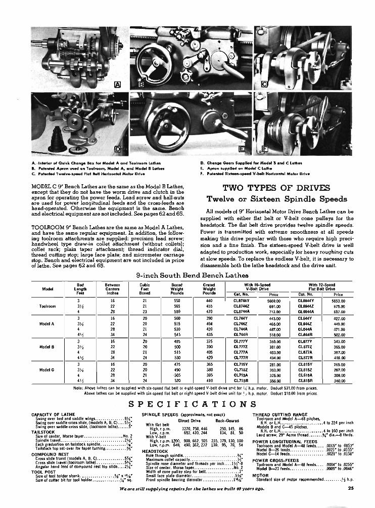
A •. lnhrior of Quick Chonll. Box for Model A ond Toolroom Lath .. •. ratented Apron u.ed on Toolroom, Model A, and Model. Lath •• C. Patented TweI ...... peed Flat Belt Horizontal Molar DrIv.
MODEL C 9' Bench Lathes are the same as the Model B Lathes, except that they do not have the worm drive and clutch in the apron for operating the power feeds. Lead screw and half-nuts are used for power longitudinal feeds and the cross-feeds are hand-operated. Otherwise the equipment is the same. Bench and electrical equipment are not included. See pages 62 and 65.
TOOLROOM 9' Bench Lathes are the same as Model A Lathes, and have the same regular equipment. In addition, the following toolroom attachments are supplied: precision lead screw; handwheel type draw-in collet attachment (without collets); collet rack; plain taper attachment; thread indicator dial, thread cutting stop; large face plate; and micrometer carriage stop. Bench and electrical equipment are not included in price of lathe. See pages 62 and 65.
D. Chanll. Gears Supplied for Model • and C Lath •• E. Apron 1Up.p11ed on Model C Lath. F. ratented SI..-.peed V-1oeIt HorIzontal Motar Drlv.
TWO TYPES OF DRIvEs Twelve or Sixteen Spindle Speeds
All models of 9' Horizontal Motor Drive Bench Lathes can be supplied with either flat belt or V-belt cone pulleys for the headstock. The flat belt drive provides twelve spindle speeds. Power is transmitted with extreme smoothness at all speeds making this drive popular with those who require high precision and a fine finish. The sixteen-speed V-belt drive is well adapted to production work, especially for heavy roughing cuts at slow speeds. To replace the endless V-belt, it is necessary to disassemble both the lathe headstock and the drive unit.
9-inch South Bend Bench Lathes Bed Between Cubic Boxed Crated With IS-Speed With 12-Speed
Model Length Cent ... Feet Weight Weight V-Bolt DrIve Flat Bolt Drive Feet Inch .. Boxed Pound. Pounds Cat. No. Pric. Cat. No. Price
3 16 21 550 440 Cl8744Y $669.00 CL8644Y $653.00 Toolroom 3% 22 21 565 455 Cl8744Z 691 .00 CL8644Z 675.00
4 28 23 580 470 Cl8744A 713.00 CL8644A 697.00
3 16 20 500 390 CL744Y 443.00 CL644Y 427.00 Model A 3)1 22 20 515 404 CL744Z 465.00 CL644Z 449.00
4 28 21 530 420 CL744A 487.00 CL644A 471.00 4)1 34 24 545 435 CL744R , 518.00 Cl844R 502.00
3 16 20 485 375 CLmY 359.00 CU77Y 343.00 Model B 3Yo 22 20 500 390 CL777Z 381.00 Cl877Z 365.00
4 28 21 515 405 CLmA 403.00 Cl877A 387.00 4)1 34 24 530 420 CLmR 434.00 CU77R 418.00
3 16 20 475 365 CLn5Y 281.00 Cl815Y 265.00 Model C 3)1 22 20 490 380 CLn5Z 303.00 Cl815Z 287.00
4 28 21 ·505 395 CLnSA 325.00 CUI SA 309.00 4% 34 24 520 410 CLn5R 356.00 Cl815R 340.00
Note : Above lathes can be supplied with six-speed nat belt or eight-speed V-belt drive unit for J.i h.p. motor. Deduct $31 .00 from prices. Above lathes can be supplied with six-speed nat belt or eight·speed V-belt drive unit for Yo h.p. motor. Deduct $10.00 from prices.
SPECIFICATIONS CAPACITY OF LATHE
Swing over bed and saddle wings .... .......... . 9J.i' Swing over saddle cross slide, (models A. B, C) .... 5)1' Swine oyer saddle cross slide, (toolroom lathe} .... . S
TAILSTOCK Size of center, Morse taper .................... No. 2 Spindle travel. ........................... . .. . 2~' Each graduation on tailstock spindle ............. \10' Tailstock top set-over for taper turnine ........... % '
COMPOUND REST Cross slide travel (models A, B, C) .......... . .. . 5~' C ross slide travel (tool room lathe) ... . .......... 5%' Angular hand feed of compound rest top slide .. .. 2J.i'
TOOL POST Size of tool holder shank ........... .•.... ",' I ".-<,' Size of cuHer bit for tool holder .............. J.i' sq.
SPINDLE SPEEDS (approximate, not exact)
Direct Drive Back-Geared With nat belt
High, r.p.m. 1270, 750, 446 250, 145, 86 low, r.p.m. 692, 410, 244 134, 81, 50
With V-belt High, r.p.m. 1200, 900, 662, 505 235, 179, 130, 100 low, r.p.m. 640, 490, 352, 272 130, 95, 70, 54
HEADSTOCK Hole through spindle ........... ................ ",' Maximum collet capacity .. ....... ... .... .. ... . .. )1' Spindle nose diameter and threads per inch ... . 1)1'-8 SIze of center. Morse taper. ........ . .......... No. 2 Width of cone pulley step for belt.. ............... 1' Small face plate diameter ................... . .. 5J.i' Front spindle bearing diameter .. ...... : ...... Jl~'
THREAD CUTTING RANGE Toolroom and Model A--48 pitches,
R.H. or l.H ........ .. .......... .. 4 to 224 per inch Models Band 1:--45 pitches,
R.H. or l.H .... .................. 4 to 160 per inch lead screw, 29" Acme thread ... .... "" dia.-8 thrds.
POWER LONGITUDINAl FEEDS Toolroom and Model A-48 feeds .... . 0015' to .0853' Model 8-26 feeds ................•. 0021' to .0155' Model C-14 feeds ........ . ... . ..... 0021'to .0156'
POWER CROSS-FEEDS Toolroom and Model A--48 feeds •.... 0004' to .0255' Model 8-23 feeds ... . . . . . . . . . . . . .. .0009' to .0046'
MOTOR Standard size of motor recommended .... . •... )1 h.p.
We are Ilia IUpplyin, repairlJor tlue lathu we built 4fJ year. "go_ 25
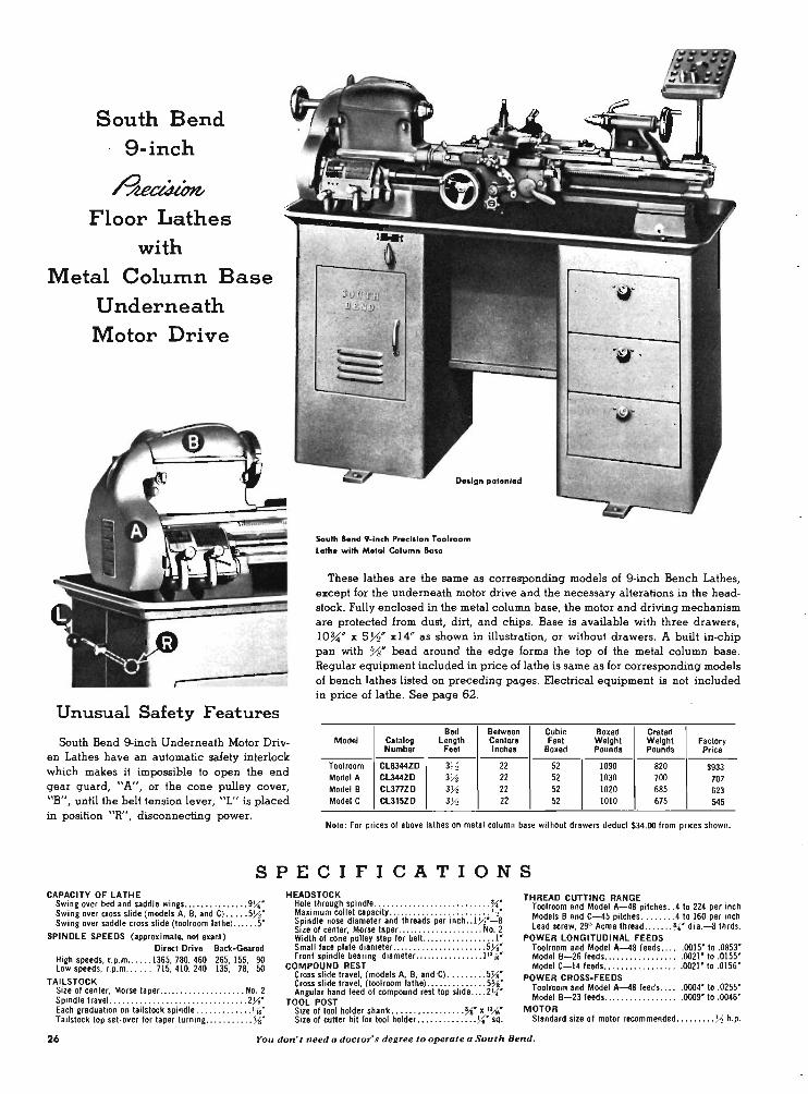
South Bend 9-inch
~ Floor Lathes
with Metal Column Base
Underneath Motor Drive
Unusual Safety Features
South Bend 9-inch Underneath Motor Driven Lathes have an automatic safety interlock which makes it impossible to open the end gear guard, "A", or the cone pulley cover, "B", until the belt tension lever, "L" is placed in position "R", disconnecting power.
Oeoign patented
South Bend 9-inch Precision Toolroom Lathe with Metal Column Bao.
These lathes are the same as corresponding models of 9-inch Bench Lathes, except for the underneath motor drive and the necessary alterations in the headstock. Fully enclosed in the metal column base, the motor and driving mechanism are protected from dust, dirt, and chips. Base is available with three drawers, IOU " x 5Y2" xl4" as shown in illustration, or without drawers. A built in-chip pan with %* bead around the edge forms the top of the metal column base. Regular equipment included in price of lathe is same as for corresponding models of bench lathes listed on preceding pages. Electrical equipment is not included in price of lathe. See page 62.
Bed Between Cubic Boxed Crated Model Catalog Length Center. Feet Weight Weight Factory
Number Feet Inche. Boxed Pound. Pounds Price
Toolroom CL8344ZD 3H 22 52 1090 820 $933 Model A CL344ZD 3)1 22 52 1030 700 707 Model B CL3nZD 3)1 22 52 1020 685 623 Model C CL315ZD 3)1 22 52 1010 675 545
Note : For prices of above lathes on metal column base without drawers deduct $34.00 from prices shown.
SPECIFICATIONS CAPACITY OF LATHE
Swing over bed and saddle wings . .. . ........... 9~" Swing over cross slide (models A, B, and C) .. . .. 5)1" Swing over saddle cross slide (tool room lathe) . . .... 5"
SPINDLE SPEEDS (approximate, not exact) Direct Drive Back-Geared
High speeds, r.p.m . . . . . • 1365, 780, 460 265, ISS, 90 low speeds, r.p.m . . . .. , 715, 410, 240 135, 78, 50
TAILSTOCK Size of center. Morse taper .. . .• •..... . ...... .. No. 2 Spindle travel. ....... . ..•........• . •........ . 2}i" Each graduation on tailstock spindle ... . . . ......• !1' Tailstock top set-over for taper turning . . ...... ... Yo"
HEADSTOCK Hole through spindle ... . . . ...... .. .. •••.. . ..•.• ".." Maximum collet capacity ...•.. . ..• . •• . .......... ' " Spindle nose diameter and threads per inch .. 1)1"-8 SIZe of center, Morse t.per . . ...... . . .. ... . •.•. No.2 Width of cone pulley step for belt . . . . . . .. . ... ... . . 1" Small face plate di.meter ..•... . .. ... •. . . ...• .. 5}i" Front spindle bearing diameter. •.•.. . •.... . . . . l'~"
COMPOUND REST Cross slide travel, (models A, B, and "C) •• • • ••• •• 5Ys" Cross slide travel, (tool room lathe) . .. .•. . . ..... . 5Yo" Angular hand feed of compound rest top slide .... 2)4"
TOOL POST Size of tool holder shank . .•••• . .•.. . . . • .. Yo" x 'l16" Size of cutter bit for tool holder ••...•... ..... ~" sq.
THREAD CUTTING RANGE Toolroom and Model A-48 pitches . . 4 to 224 per inch Models Band C-45 pitches. · . . . .... 4 to 160 per inch lead screw, 290 Acme thread .... . .. ".." dia.-8 thrds.
POWER LONGITUDINAL FEEDS Toolroom and Model A-48 feeds .•• .. 0015" to .0853" Model B-26 feeds . . .. . ... . .. .. . . .• . 0021" to .0155" Model C-14 feeds .... . .. . .. . .. . . ... 0021" to .0156"
POWER CROSS-FEEDS Toolroom and Model A-48 teeds .... . 0004" to .0255" Model B-23 feeds . •.... . . . . . .. . .. . . 0009" to .0046"
MOTOR Standard size of motor recommended •• •• .... . )1 h.p.
26 You don' t need a doctor's degree to operate a South Bend.

Model A '-Inch Floor
Lothe with Self-ConJoined
Flat hit DrIve
The 9-inch Model A Self-Contained Motor Drive Floor Lathe is illustrated above. The Model B, Model C, and Toolroom Lathes are also made with this drive. Except for the self-contained drive equipment, chip pan, and floor legs, these lathes are the same and have the same equipment as corresponding models of 9-inch Bench Lathes described on the preceding pages. Specifications are also the same, except for shipping weights. See pages 24 and 25.
South Bend
9-inch
Self - Contained
Motor Drive
~ Floor.
Lathes
Either flat belt or V-belt cone pulleys are supplied for the headstock. The flat belt drive transmits power with the extreme smoothness required for high precision and fine finish. The
The self-contained drive equipment is permanently mounted V-belt drive is well adapted to production work, especially for back of the lathe headstock and consists of the· self-contained heavy roughing cuts at slow speeds. To replace the endless motor drive unit (patented) for Y2 h.p. motor; motor pulley V-belt, it is necessary to disassemble both the lathe headstock with ~. hole; belt guard for motor belt; and necessary belting. and the drive unit.
Self-Contained Motor Drive 9-inch South Bend Floor Lathes Bed Between Cubic Boxed Crated With IS-Speed V-belt With 12-Speed Flat Belt
Model Length Centero Feet Weight Weight Self-Contained Drive Self-Contained Drive Feet Inches Boxed Pounds Pounds CaL No. Price Cat. No. Price
3 16 30 835 660 CL8244Y $759.00 CL8944Y $743.00 Toolroom 3~ 22 30 860 685 CL8244Z 782.00 CL8944Z 766.00
4 28 34 885 710 CL8244A 805.00 CL8944A 789.00
3 16 30 775 600 CL244Y 533.00 CL944Y 517.00
Model A 3)-2 22 30 800 625 CL244Z 556.00 CL944Z 540.00 4 28 34 825 650 CL244A 579.00 CL944A 563.00 4~ 34 34 850 615 CL244R 611.00 CL944R 595.00 3 16 30 160 585 CL277Y 450.00 CU77Y 433.00
Model B 3)-2 22 30 185 615 CL277Z 473.00 CL977Z 456.00 4 28 34 815 635 CL277A 496.00 CL977A 479.00 4)-2 34 34 835 660 CL277R 528.00 CU77R 511.00 3 16 30 140 515 CL215Y 312.00 CL815Y 355.00
Model C 3~ 22 30 115 605 CL215Z 395.00 CUl5Z 378.00 4 28 34 805 625 CL215A 418.00 CL815A 401.00 4~ 34 34 825 659 CL215R 450.00 CL815R 433.00
Many bUrul con and do own and operate South Benth-Know why' 27

Collet attachment, electrical equl~ent, Iplolh pan, coolant reservoir, and pump Ihown in iIIultration are not included in price of lathe.
No. 2-H ~ Turret Lathe Designed for the efficient production of duplicate parts, the
South Bend No. 2-H Turret Lathe has the precision for exacting close-tolerance operations, smooth power for producing a fine finish, and versatility that reduces set-up time to a minimum.
The universal carriage has 48 power cross-feeds, 48 power longitudinal feeds, and 48 thread cutting feeds ranging from 4 to 224 per inch. All changes are made through the quick change box at the headstock end of the lathe. Front and back tool blocks are supplied on the screw feed cross slide and a 4-way turret tool block is available to order. The large diameter micrometer graduated collar on the cross slide handwheel permits adjusting the cutting tools with extreme accuracy.
The ram-type turret has both power feed and hand feed, with an adjustable feed trip and stop for each of the six turret faces. The turret head indexes automatically on the return stroke of the turret slide. The quick change box provides 48 changes for power turret feeds. Change gears in the turret apron provide an additional change for turret power feed, independent of the universal carriage feeds in both rate of feed and direction of feed. Turret ram lock is provided.
Full advantage may be taken of the higher cutting speeds of tungsten carbide tools as the result of the wide range of
speeds and feeds available. The use of a two-speed motor permits quick change from high speeds to low speeds for reaming and tapping operations.
Equipment included in the price of lathe consists of: universal carriage with screw feed double tool slide having front and rear square tool blocks; power feed ram-type turret; quick change box; oil pan; coolant return assembly; wrenches; and installation plan. Electrical equipment, handlever collet attachment, collet splash guard, coolant reservoir, coolant pump, splash pan, and piping are not included in price of lathe. See page 62 for motors and controls.
No. 2-H Turret Lathes with Power Feed Carriage and Turret
Catalog Bed Cubic Boxed Crated Factory Length Feet Weight Weight Number Feet Boxed Pounds Pounds Price
CL2CT 6 115 3175 2810 $3350 CL2DT . 7 130 3300 2900 3413
Not_Thel. lathe. can be supplied with hand feed only for the turret if desired. Write for information.
Specifications of No. 2-H Turret Lathes CAPACITY OF LATHE
Hole through epindle ..................•....... 1 ~" Swing over double 1001 troIS slide .............. 8}f' Swing over bed and saddle wing • ..... .. . . ..... 18~* Width of lathe bed .. . ........................ 11 ~' Spindle nose diameter and thread. per inch . ... 2~·-6 Maximum collet capacity through handlever
collet chuck . ... . ................... . .... . .... 1"
SPINDLE SPEEDS (Standard spindle epeed. with . two-speed motor, approximate, not exact) High spindle speeds
r.p.on. of epindle, direct belt drive ..... 945, 550, 300 r.p.on. of spindle, backllear drive ....... 118, 70, 32
Low spindle speeds (Not available with l-epeed motor) r .p.m. 01 spindle, direct belt drive ..... 475, 278, 150 r .p.on. at spindle, backllear drive ........ 60,33,20
TURRET Diameter of holes in turret lacea ..... . ........ . 1).<i" Center of turret hole to top 01 turret slide . . .. . .. . 2).<i" Effective leed 01 turret slide ....... . .. .. ... . .. . 5]1" Distance between opposite flats ...... . .. . ...... 9~" Maximum distance belween spIndle nose
and turrellace at beginning of indexing movement .. . ....... 6 IL bed 28~", 71L bed 40~"
UNIVERSAL CARRIAGE Thread cutting range ............... 4 to 224 per inch Power longitudinal leeds ......... . . • 0015* to .0841" Maximum longitudinal travel .... ... ... 61L bed 22 ).<i"
7ft bed 34 1 ~" Power ero .... leeds, 48 .. ....... .... . . . 0006' to .0315" CroSl travel 01 erOlS slide ......... ..... .. ... . .. 9~' Tool block openings lor cutter bits .......... ~' x ~*
MOTOR For operating on
3-phase ,,"C •.. 2-speed. 1800-900 r.p:on., 2 h.p.-l h.p. For operating on
l-phase ,,"C. or D.C ... 1-speed, 1800 r.p.m., 1}<l h.p.
28 More precision for )lour money thDn you can buy elsewhere.
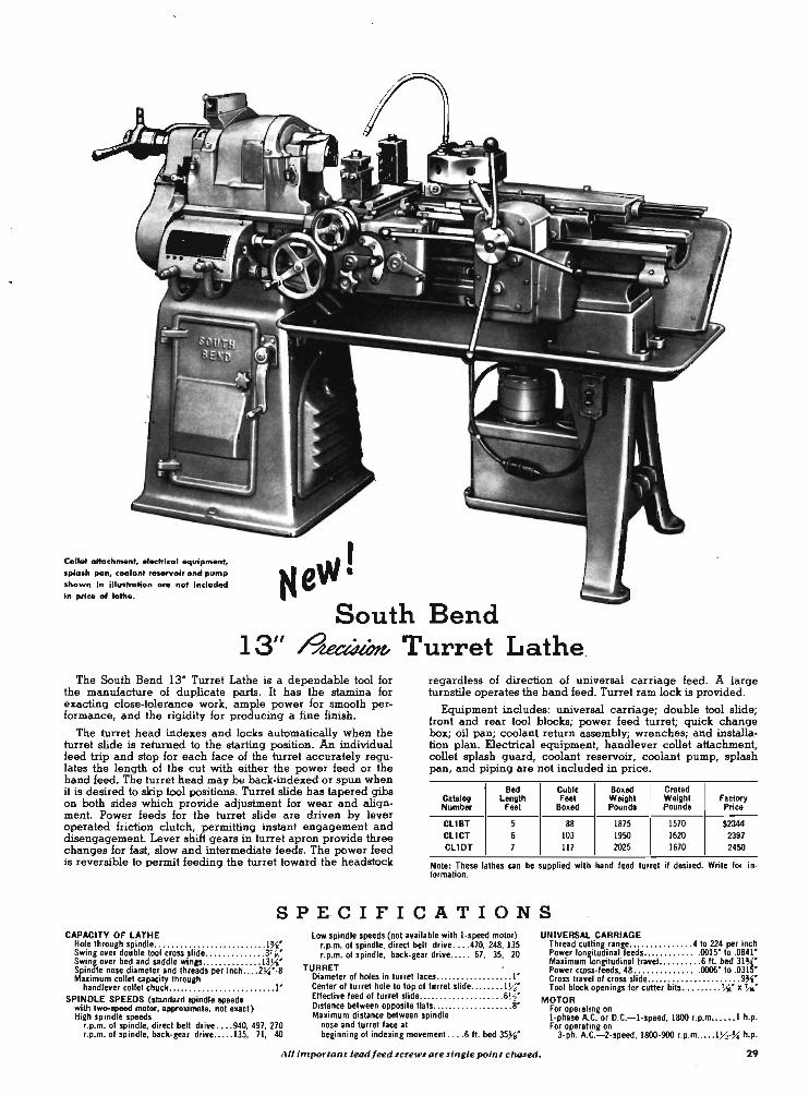
Collet attachment, eledrical equipment, splash pan, coolant reHf'Voir and pump shown in iIIultration are no. included In price of lathe.
I Ne\'la South Bend
13" ~ Turret Lathe The South Bend 13" Turret Lathe is a dependable tool for
the manufacture of duplicate parts. It has the stamina for exacting close-tolerance work, ample power for smooth performance, and the rigidity for producing a fine finish.
The turret head indexes and locks automatically when the turret slide is returned to the starting position. An individual feed trip and stop for each face of the turret accurately regulates the length of the cut with either the power feed or the hand feed. The turret head may be back-indexed or spun when it is desired to skip tool positions. Turret slide has tapered gibs on both sides which provide adjustment for wear and alignment. Power feeds for the turret slide are driven by lever operated friction clutch, permitting instant engagement and disengagement. Lever shift gears in turret apron provide three changes for fast, slow and intermediate feeds. The pOwer feed is reversible to permit feeding the turret toward the headstock
regardless of direction of universal carriage feed. A large turnstile operates the hand feed. Turret ram lock is provided.
Equipment includes: universal carriage; double tool slide; front and rear tool blocks; power feed turret; quick change box; oil pan; coolant return assembly; wrenches; and installation plan. Electrical equipment, handlever collet attachment, collet splash guard, coolant reservoir, coolant pump, splash pan, and piping are not included in price.
Bed Cubic Boxed Craled Calalog Lenglh Feel Weighl Weight Factory Number Feet Boxed Pounds Pounds Price
CL1BT 5 88 1875 1570 $2344 CL1CT 6 103 1950 1620 2397 CLIDT 7 117 2025 1670 2450
Note: These lalhes can be supplied WIth hand leed turret II desired. Write lor Inlormation.
S P E· elF I CAT ION S CAPACITY OF LATHE
Hole through spindle ....... .... ............ ... I~· Swing over double tool cross slide .. .. ...... . ... 3' ... • Swing over bed and saddle wings .. ........... . 13~·
. Spindle nose diameter and threads per inch .... 2~·-8 Maximum collet capacity through
handlever collet chuck .. ....................... 1' SPINDLE SPEEDS (slanda.d spindle &peeds
with two-speed motor, approximate, not exad) High spindle speeds
•. p.m. 01 spindle, direct belt drive . ... 940,497,270 •. p.m. 01 spindle, back-gear drive ..... 135, 71, 40
low spindle speeds (not available with I -speed motor) •. p.m. 01 spindle. direct belt drive .... 470, 248. 135 ' .p.m. 01 spindle; back-gear drive ..... 67, 35, 20
TURRET Diameter 01 holes in turret laces .. .. ........ . ..... 1' Center 01 turret hole to top 01 turret slide . .. . . ... I~· Eflective leed 01 turret slide ... .. ........ . .. . ... 6~· Distance between opposite lIats .......... .. . . . . . . . 8' Maximum distance between spindle
nose and turret lace at beginning 01 indexing movement. ... 6 fl bed 35~'
UNIVERSAL CARRIAGE Thread cutting range ....... ..... . .. 4 to 224 per inch Power longitudinal leeds ..... ...... . . 0015' to .0841' Maximum longitudinal travel.. . . . ... . . 6 ft. bed 31~' Power cg)S$-leeds, 48 ... . ......... . . 0006' to .03IS· Cross travel 01 cross slide ...... ...... .... . . .... 9~· Tool block openings lor cutter bits . _ . .. . ... '" x '"~
MOTOR for operating on I -phase A.C. or D.C.-I -speed, 1800 r.p.m ...... 1 h.p. for operating on
3-ph. A.C.-2-speed, 1800-900 I.p.m .. ... 1J4-~ h.p_
All important lead/eed screws are lingle point clwled. 29

Th. bed turret, do ubI. tool croll llid. and other accelloriel lupplied with thil lathe are olio lold separatefy and are U.ted in attachment sadfon of catalog.
SPECIFICATIONS CAPACITY OF LATHE
Hole through spindle . ... " ........ . ... .. .... . . 1 ~" Swing oyer bed and saddle wings . .. .......... . 10Ys" Width of lathe bed ........... ... . ......... . .. . 7}{r Spindle nose diameter and threads per inch . . .. 27.("-8 Maximum collet capacity through handleyer
coItet chuck ... . ... . ...... . . ... . . ... ..... . .. . . 1" Maximum capacity through uniyersal
tathe chuck ............ .. .... ' ... . .. ... .. , . 1 ~"
TURRET Diameter of holes in turret faces " ............ . .. Vo' Center of turret hole to top of turret slide .. ...... 1)4" Effective feed of (urret slide . . . ............... .. . 4" Distance between opposite flats .. . .... .. . ..... . 4Ys" Maximum distance between spindle nose and tur-
ret face at beginning of indexing moyement . . . 19~"
SPtNDLE SPEEDS (approximate, not exact) Direct Drive Back-Geared
With one-speed motor High speeds. r.p.m •. .. . 1400, 898, 585 250, 160, 105 Low speeds. r.p.m. ... .. 740, 470, 304 130, 85, 55
With two-speed motor High speeds, r.p.m. ... . 1400, 898. 585 250, 160, 105
740, 470, 304 130, 85, 55 Low speeds. r.p.m. ... . . 700, 449. 292 125, 80, 52
370, 235, 152 65, 42 27
UNIVERSAL CARRIAGE
Thread cutting range .... .. .. .. .. .. . 4 to 480 per inch Power longitudinal feeds . . . . . . . . . .. ,0007" to .0836" Maximum longitudinal travel of universal
carriage. hand or pOwer feed .................. 16"
DOUBLE TOOL CROSS SLIDE Swing over double tool cross slide . . ... . ....... ,3liA" Cross trayeJ of cross slide . . . .. . ... .... .. ..... . 3Vo· Maximum size cutter bit toot bldck opening
will take .. ..... .. ............. .... . .... liA· x Ke" Power cro .... feeds ........... . ..... . 0003' to .0303"
MOTOR (recommended size) One-speed .... .. . . . . . . . .......... ... . . . . ... ~ h.p. Two-speed ............ .. ...... .. .. ... . . . . Y.I"l h.p.
*Can be supplied to order with ~' holes in turret head. No extra charge. ,
,
South Bend 1 0" ~ Turret Lathes South Bend 10' Turret Lathes are made with 3 Y2' bed
length and with either bench or floor mounting, as illustrated. They are precision tools capable of fast, efficient production and are easily adaptable to a wide variety of work. There is no excessive weight in moving parts to slow down operation and cause fatigue. These lathes can be equipped with a one-speed motor or a two-speed motor to provide twelve or twenty-four spindle speeds as listed 'in the specifications.
The turret is mounted on the inside bed ways and can be locked in position at any point along the length of the bed. The turret base can be placed close to the headstock 'to eliminate excessive overhang of the work or the turret tools. Turret head indexes automatically when the lever is moved to the extreme right, and has individual stops for each of the six turret faces. The turret head will index within plus or minus.OOO5~ measured 4" from turret face and it may be back indexed or spun to skip tool positions. Turret ram slide can be locked for mounting work between centers if desired.
Equipped with front and rear tool blocks the hand· lever cross slide has adjustable stops which limit the movement of the cross-feed in either direction, in or out. The handlever can be removed and the cross-feed screw attached, permitting use of all power cross-feeds and longitudinal feeds with the double tool cross slide. See small illustration at right.
feed double tool slide having front and rear square tool blocks; handlever bed turret; quick change box; oil pan; coolant return assembly; splash guards; wrenches; and installation plan. Bench turret lathes also include rigid tubular steel bench with three roomy drawers.
Type Cubic Boxed Crated Catalog of Feet Weight Weight Factory Number Mounting Boxed Pounds Pounds Price
CL1006Z Floor 59 1350 1050 $1601 CL1005Z Bench 56 1250 950 1641
NOTE: Splash pan, tailstock, compound rest, centers,spindle sleeye, face plates, draw· in collet chuck attachment, lathe chuck. thread cutting stop, coolant equipment, and electrical equipment are not included in price of lathe. See attachment sec· tion of catalog for these a~ssories.
Equipment included in the price of turret lathe consists of: underneath motor drive unit (patented); universal carriage with combination handlever and screw Doubl. Toot SUd. with Screw Feed South Bend IO ' Bench Turret Lathe
30 You'llfind your fini$hes are better when you ule South Bend.

Turret Lathe Conversion Units for .All 9" and Light Ten South Bend Lathes
Any South Bend g" or Light Ten La,the, either bench or floor type, can be supplied as a turret lathe with handlever bed turret and combination handlever or screw feed doUble tool cross slide in lieu of the regular tailstock and compound rest assemblies. When this equipment is wanted, Turret Lathe Conversion Units as listed below
, must be specified when the lathe is ordered.
Handlev.er Bed Turret The handlever Bed Turret mounts on the inside bed ways and
can be locked in position at any point along the length of the bed. The turret head indexes automatically when the feed lever is pushed to the extreme right. Each face of the turret has an independently adjustable feed stop screw which accurately regulates the length of the cut.
Accurate indexing of the turret head (within plus or minus .0005" measured 4" from turret face) is assured by the use of hardened, ground and superfinished index pin which operates in heat·treated steel bushings.
The effective feed of the turret slide is 4'. Turret ram slide lock is provided. Center 'of turret hole to top of turret .slide 1 >-2". Turret holes take standard turret tools with %" diameter shank. If specified when lathe is ordered, turret head can be bored to order to take tools with 3-4" diameter shank, no extra charge. Distance between opposite flats on turret head is 4 Ys".
Combination Double Tool Slide The combination Handlever and Screw Feed Double Tool
Cross Slide is mounted on the saddle cross slide dovetail in place of the compound rest assembly. The handlever can be used on either side of the cross slide. Adjustable stops limit the movement of the cross slide in either direction, in or out. Power longitudinal carriage feeds can be used with either the handlever cross-feed or screw cross-feed. The handlever feed is easily removed and replaced with the screw operated cross-
feed. Power cross-feeds are a~ailable with the screw cross·feed. Cross·feed screw and nut can be supplied with either English or metric thread and graduations.
This cross 'slide has front and hack square tool blocks in which )16" square cutter bits can be mounted for multiple tum· ing, forming, facing and cutting-off operations. The front tool block takes two cutter bits and the hack tool block takes one cutter bit. Tapered wedges and thumb screws provide adjustment for the height of cutter bits. Maximum swing over Double Tool Cross Slide is 3?16", 'maximum travel of cross slide 3 %'. T-slots in the cross slide base permit adjusting the positions of the tool blocks.
Turret Lathe Conversion Units Prices for Turret Lathe Conversion Units listed below ate for
handlever bed turret and combination handlever and screwfeed double tool cross slide in lieu of compound rest, tailstock, centers, spindle sleeve, tool post and small face plate. These prices apply only when Turret Lathe Conversion Units are specified when lathe is ordered. See attachment section of catalog if turret equipment is wanted for lathes now in service.
Turret Lathe Conversion Units for 9" and Light Ten Lathes
Catalog Si •• Factory Nuznbel' Lath. Type of Drin Price
CL381SN 9" Ho.uontal Motor Drive, V·belt or flat belt $377
CL3816N 9" SeU·Contained Drive, V·belt or flat belt 377
CL3817N 9" Underneath Motor Drive 367
CL3815K Lt. Ten Horizontal Motor Drive, V·belt or flat belt 382
CL3816K Lt. Ten SeU-Contained Drive, V·belt or flat belt 382 - - -
CL3817K Lt. Ten Underneath Motor Drive 371
When you IUlIIe II Iathe-You lui .... the king of toob. 31

4" Type DI CaIn Lock Spindle Size 00 Long Taper Key Drive Spindle
South Bend Lathes Equipped With Cam Lock and Long Taper Key Drive Spindles
All South Bend Lathes, 10' -1 ' Collet and larger, can be supplied with 4" Type Dl Cam Lock Spindles or Size 00 Type L Long Taper Key Drive Spindles, in lieu of the regular threaded spindles at extra cost. Price includes small face plate which is supplied with the lathe, but does not include large face plate, chucks, draw-in collet attachments, or other accessories. Spin. dle nose dimensions conform with ASA standards, but spindle bore and inside taper are larger to accommodate South Bend collet equipment, spindle sleeves, and centers. See attachment section of catalog for descriptions of chucks, collet equipment, and other accessories for these lathes.
Sia. of
Lathe
10" 13" 14 ~" IS", 16-24", & 2-H
Size 00 Long Taper Key Dri.e Spindle Nose in Lieu of Reg-
War Threaded Spindle No ..
Cat. No. P ric e
CA80SOL $25.00 CA80SOT 38.00 CA80SOF 4S.00 CA80SOH 52.00
Distances Between Centers for Lathes with 4" Type DI CaIn Lock Spindles
Size Diatance Between Centers of
Lathes 3' bed 3 y.' bed
. ' bed .~' bed 5' bed 6' bed 7' bed 8' bed
10" 13" 19" 26" 33"
13" IS" 27" 39" 51"
14 ~" 23" 35" 47" 59"
16" 32" .. " 56"
16-24" 29" 41" 53"
. " Can> Lock Spin-dl. Nose in Lieu o[ Regular Threaded
Spindle Nose
Cat. No. Price
CB80SOL $33.00 CBBOSOT 38.00 CBB050F 4S.00 CB8050H 52.00
10' bed 12' bed
80' 104"
77" 101"
Distances Between Centers for Lathes with Type L Long Taper Key Drive Spindles
32
Size of
Lothes
10"
13"
14 ~"
16"
16·24"
3'bed
13"
3 ~' bed . ' bed IS' 25"
IS"
Diatance B.tween Centers
. ~' bed 5' bed 6' bed 7' bed 8' bed 10' bed 12' bed
33"
27" 39" 51 "
23" 35" 47" 59"
32" .. " 56" 80" 104"
29' 41" 53" 77" 101"
South Ben4 is leDding--<)thers follow.

Accessories for Lathes With 4" Type Dl Cam Lock Spindles
For 10" Lath. For 13" Lathe For 14~" Lath. For 16", 16-24",2-H Description
Cat-log Fae. Cat-log Fac. CaWoq Fac. CaWoq Fac. Nu:rnber Price Number Price Nu:rnber Price Number Price
A Handwheel Collet Allachment ...... ............... CB4306L $ 61.00 CB4306T $ 66.00 CB4306F $ 70.00 CB4306H $ 73.00 B Handlever Collet Allachment .... . ...... .. ............... CB5206L 129.SO CB5206T 143.00 CB5206F 156.00 CB5206H 169.00
Closer for Step Chuck. 3' and 4' maximum capacity .. .. ... CB6309LH 13.25 CB6309LH 13.25 CB6309LH 13.25 CB6309LH 13.25 c: Closer for Step Chucks 5" and 6' maximum. capacity ....... CB6311LH 17.SO CB6311LH 17.SO CB6311LH 17.SO CB6311LH 17.SO D Small Face Plate ... .. .. . . . . . . . ...... . ............ _ ... .. CB217SLT 18.SO CB2175LT 18.SO CB2175FH 27 .SO CB2175FH 27.SO E Large Face P1ate ...... .. .. .. ............... ...... . .... - CB2180L 25.25 CB21SOT 27.SO CB2180FH 37.25 CB2180FH 37'.25 F Fixture Plate . ... . ...... . . ... .. . ........... , ..•...... . .. CB46L 17.SO CB46T 19.00 CB46FH 20.SO CB46FH 20.SO
6 " 4-Jaw Independent Chuck ... .. . . .. • ... . . _ . . _ . .. . .•... CB4006 SO.OO CB4206 " . i14.00 ... .... .. .. . . . . . . . . . . .
6" 4-Jaw Independent Chuck ... . ..... . .. _ . . .. . ... _ . . . . . . CB4206 84.00 CB4207' . CB4207 " . 98'.00 G 7 ~" 4-Jaw Independent Chuck .. . . .. ... . .... .... .. .. .. .. CB4207 98.00 CB4207 98.00 98 .00 g" 4-Jaw Independent Chuck . . .. . .. . . ... . .. . ... .. ....... . . . . . . . . . . . CB4209 112.00 CB4209 112.00 CB4209 112.00 10" 4-Jaw Independent Chuck ............ . .......... .. .. ........... . .......... CB4210 122.00 CB4210 . 122.00 12" 4-Jaw Independent Chuck ............ ... ... ... ...... ...........
69.00 CB3OOS " . . . . . . . . . . . . CB4212 158.00 5' 3-Jaw Universal Chuclc With two lela of jawI-l pinion ... CB3OO5 69.00 CB35OS " . .. .... ..... .
i ·13·.00 5' 3-Jaw Universal Chuck with tw,o sets of iawa-3 pinions .. CB3505 113.00 CB3S05 113.00 113.00 CB3505 H 6' 3-Jaw Universal Chuck with two sets of jaws . . .......... CB3506 121.00 CB3506 121.00 CB3506 121.00 CB3506 121.00
7 ~' 3·Jaw Universal Chuck with two seta: of jaw • ... . ...... ..... ..... . CB3507 137.00 CB3507 137.00 CB3507 137.00 9' 3·Jaw Univer.al Chuck with two seta of jaws .... . .. . .... CB2935 ' .. 2i50 CB2935 " . CB3509 184.00 CB3509 184.00 Chuck Plate filled to chuck ......... : ....... . .... . .. • .... 27.SO CB2935 27 .SO CB2935 27.SO Semi-Machined Chuck Plate-5" . ... .. .. . .... . ... . . . .. ... CB2704RH 17.SO CB2704RH 17.SO CB2704RH 17.SO CB2704RH 17.SO Semi-Machined Chuck Plat~ U" . .... . ... . ... . . . ....... CB2707RH 18.SO CB2707RH 18.SO CB2707RH 18.SO CB2707RH 18.SO Semi-Machined Chuck Plate-g" .... . . CB2709RH 19.5O CB2709RH 19.5O CB2709RH 19.5O CB2709RH 19.5O
J Collet Splash Guard .. .. .......... . ... : : : : : : : : : : : : : : : : : : CB5223L 4.SO CB5223T 4.75 CB5223F 5.SO CB5223H 7.00
Accessories for Lathes With Type L Long Taper Key Drive Spindles
For 10" Lath. For 13" Lathe For 14~" Lathe For 16", 16-24", 2-H Description
CaWoq Fac. CaWoq Fac. CaWoq Fac. CaWoq Fac. Number Price Number Price Number Price Number Price
A Handwheel Collet Allachment .. . . .. .. . ......... . ........ CA4306L $ 61.00 CA4306T $ 66.00 CA4306F $ 70.00 CA4306H $ 73.00 B Handlever Collet Allachment ........... .. . .. . ... ....... . CA5206L 129.SO CA5206T 143.00 CAS206F 156.00 CA5206H 169.00
Cloler for Step Chucu 3' and 4' maDmUlD capacity ....... CA6309LH 13.25 CA6309LH 13.25 CA6309LH 13.25 CA6309LH 13.25 c: Closer for Step Chuclta S" and 6" muimum capacity . . .. . _ . CA6311LH 17.SO CA6311LH 17.SO CA6311LH IT.SO CA6311LH 17.SO D Small Face Plate .. . ... . . . .. . .... . ........... . ..... . ... . CAZ175L 18.SO CA2175T 18.SO CA2175FH 27.SO CA2175FH 27 .SO E Large Fac. Plat • .. ... . .... ... .. .. . . .... . ......... . ..... CAZl80L 25.25 CAZ1SOT 27.SO CAZl80FH ' 37.25 CA2180FH 37.25 F Fixture Plate .. .. .... .. .. . .. ... .......... . . . . .. . .. .... .. CA46L 17.SO CA46T 19.00 CA46FH 2O.SO CA46FH 20. SO
6" 4-Jaw Independent Chuck .................. . .... •. ... CA4006 SO.OO .. ......... . . 8'4.00 . ...... .... . ..... .. . . . 6" 4-Jaw Independent Chuck .. . . ... ..... . ....... , . . ..... CA4206 84.00 CA4206 CA42Oi " . " 98'.00
. . . . . . . . . . . . ' 98'.00 G 7 ~" 4-Jaw Ind\lpendent Chuck .. . . . ..................... CA4207 98.00 CA4207 98.00 CA4207
g" 4-Jaw Independent Chuck .. . .. . .................. .. .. . ..... .. . . . CA4209 112.00 CA4209 112.00 CA4209 112.00 10" 4-Jaw Independent Chuck .................. . ... . .... . . . . . . . . . . . . . . . . . . . . . . CA4210 122.00 CA4210 122.00 12" 4 .Jaw Independent Chuck ... . . . ........... .. .. .. . . .. ... ..... . ..
69:00 CA3OOS '" ........... CA4212 158.00
5" 3-Jaw Universal Chuck with two sela of iaws-1 pinion .. . CA3OO5 69.00 CA35OS '"
...... ... .. . i '13:00 5 " 3·Jaw Universal Chuck with two sela of jaws-3 pinions .. CA350S 113.00 CA3505 113.00 113.00 CA3505
H 6" 3·Jaw Universal Chuck with two seta of jaw • . . .......... CA3506 121.00 CA3506 121.00 CA3506 121.00 CA3506 121.00 7!-i" 3·Jaw Universal Chuck with two seta of jaws . . ........ ... ... .. ... CA35O'1 137.00 CA3507 137.00 CA3507 137.00 9" 3·Jaw Universal Chuck with two set. of jaw • . ...... . .... CA2935" . CA2935 " . CA3509 184.00 CA3509 184.00 Chuck Plate filled to chuck .. ................ . ............ 27 .SO 27.SO CA2935 27.SO CA293S '27 . SO
I Semi-Machined Chuck Plate-5" ................. . . . .. .. . CA2704RH 17.SO CAZ704RH 17.SO CA2704RH 17.SO CA2704RH 17. SO Semi-Machined Chuck Plat~U" ... . ..... . . .. . . ... .. ... CA2707RH 18.SO CA2707RH 18.SO CAZ707RH 18.SO CAZ707RH 18.SO Semi-Machined Chuck Plate-g" ...... .. . .......... .. . . .. CAZ709RH 19.5O CAZ709RH 19.5O CA2709RH 1~ . SO CAZ709RH 19.5O
J Collet Splash Guard .......... . .. ... ........... ..... . . .. CA5223L 4.SO CA5223T 4.75 CA5223F .SO CA5223H 7.00
Why can't copier. and imitators duplicate quality' 33

Special Paint Colors and Styles Color Code
Highlighting
Single or Multicolor South Bend Lathes and other
Machine Tools can be finished to order in any special color of paint, or in any combination of two or more colors to conform with your own color code or specifications. When special colors are wanted, color samples for matching must be supplied. If certain portions of the machinery are to be finished in diHerent colors, clear and specific instructions indicating the exact portions for each color must be supplied. Finish enamel may be supplied by purchaser if desired, but no allowance or deduction for it can be made.
Size and [) 2·H. 16-24', 16', 14~' Type of & 13' Lathe. Machine Milling Machine
Color. Cat. No. Fae. Price
One Special Solid Color CE2660 $37.50
Mul1icolor lst Color CE2663 37.50
Multicolor, each extra color CE2666 26.75
10' Bench & Floor, 9' & Light Ten 9' & Light Ten HMO Bench Lathea , UMD and Self· ConI. Drive Floor Lathes, Shaper, Pedeatal Grinder,
3 & 4 Spindle Drill Preaaea 1 & 2 Spindle Drill Presses
Cal. No. Fac. Price Cat. No. Fac. Price
CE2661 $25.50 CE2662 $13.00
CE2664 25.50 CE2665 13.00
CE2667 21.50 CE2668 8.50
Hardened and Ground Bed Ways South Bend Lathes 10" and larger can be sup
plied with hardened and ground bed ways in lieu of regular bed ways at extra cost as listed in the tabulation below. Heat-treating produces a hardness of 50-55 Rockwell C on the surface of all bed ways throughout the wearing area of the bed. After a period of seasoning, the bed ways are finished by precision grinding on equipment especially de-signed and built for the purpose. .
Hardened bed ways resist wear and scoring. They are especially recommended for lathes that ar~ to be used for machining rubber, plastics or other abrasive materials, also for machining tool steel or other materials which may produce sharp work hardened chips.
Catalog Size Bed Length Factory Number Feet Price
CL4955Y 10' 3 $145 CL4955Z 10' 3Y. 150 CL4955A 10" 4 155 CL4955R 10' 4~ 160
CL4956A 13' 4 175 CL4956B 13' 5 186 CL4956C 13' 6 197 CL4956D 13' 7 208
Catalog Size Number
CL4957B 14~'
CL4957C 14~'
CL4957D 14~'
CL4957E 14W
CL4956C 16', 16·24' & 2·H CL4956D 16', 16·24' & 2· H CL4956E 16', 16·24' CL4956G 16', 16·24' CL4956H 16', 16-24'
34 You, choice of accessories iI the greatest In the world.
Bed Length Factory Feet Price
5 $200
6 212 7 224 8 236
6 225 7 239 8 253
10 281 12 309

Attachments and Accessories for South Bend Lathes A complete assortment of attachments and accessories greatly increases the adapta
bility of any lathe. Often a careful selection of equipment will save much loss of time and the expense of making special tools or fixtures. It is recommended that attachments and accessories be ordered with the lathe so that any fitting that may be required can be done at the factory.
!AI Handwheel Collet Attachment This aHachment is a great time-saver in mounting small work in the lathe for production,
toolroom, and maintenance operations, especially when extremely accurate centering is required. Bar and tube stock can be fed through the hollow draw·bar which operates the collet. When the hand· wheel is tightened, the collet automatically grips and centers the work. Equipment includes steel draw·bar with handwheel, spindle nose cap, spanner wrench, and heat·treated steel closing sleeve if required. Collets are not in· cluded. See page 36.
Catal09 Nuftlbar
Siae of Lathe Collet U..d
Max. Ship- Fac-Collet ping tory Cap. Weight Price
-------�-----------------�----------�----~ CL4306N CL4308K CL4306L CL4306Q CL4306M CL4306H
IJqhl Ten 10" 13'
• 1 .. %" IS'. 16-2 .. •• 05< 2-H
No. 3 No. SK No. 5 No.5 No. 5 No. 5
%' %' l' l' l' l'
Sib •. 51ba.
10 lb •. 1 .. 1ba. 1 .. 1ba. 151ba.
$19.75 22.SO SS.OO 60.00 64.00 67.00
[§) Handlever Collet Attachment Speed and accuracy are combined in the Handlever Collet AHachment. Without stop
ping the lathe spindle, the collet can be released, bar stock fed through the spindle, and the collet tightened again. Equipment includes adjustable chuck closing mechanism and hollow
Cataloq Nuftlb ...
Siae of Lathe Collet U..d
Max. Ship- Fac-Collet pinq tory .Cap. Weight Price
draw-bar, spindle nose cap, spanner wrench CUld heat-treated steel closing sleeve if required. Collets are not included. See page 36.
-----~I-----------------I----- -----------
This aHachment should be ordered with the lathe so that it can be p;r:operly fiHed at the factory.
CL5206N CL5206K CL5206L CL5206Q CL5206M CL5206H
IJqhl Ten 10" 13'
14 %' IS', 16-2 .. • . ... 2-H
IQJ Collet Splash Guard
No. 3 No. SK No. 5 No. 5 No.5 No.5
l' I" l' I'
10 Iba. 10 lb •. 20 Iba. 2S Iba. 31 Iba. 321ba.
$ 78.SO 92.SO
123.SO 137.00 lSO.00 163.00
IDI Collet Rack To prevent chips or coolant from flying off of lathe spin
dle, the collet splash guard is aHached to the lathe headstock as shown above. Guard hoob into socket head cap screws and fits snu9ly around ~indle nose and collet, but does not interfere with use of collet aHachment. All lathes fiHed with both collet aHachment and coolant equipment should also be equipped with one of these guards.
This collet rack provides a convenient place for keeping collets, centers, spindle sleeve, and draw-bar. Tray along lower edge of collet rack is provided for holding spanner wrench. Clamp for aHaching to back V-way of lathe bed is supplied. Price does not include collets or collet aHachment.
Cataloq Sia. of Lathe Nuftlbv Cat. No. Siae and Type of Lathe Ship. Wt. Price
CEI770N 9' ................ .. CL5223NK 9' Underneath M.D .. . ........ . . 2 Iba. $2.95 CL5200N 9' Horizontal M.D .. .... . .•.... .. 21ba. 3.00 CL5200K IJqhl Ten H.M.D ...... .... ..... . 2 Iba. 3.25 CL5223R 10" Underneath M.D . ........ . . . 21ba. 3.SO
CEI770K IJqhl Ten ........... . . . . . ... CEI770L 10"·1' Colle! . .............. . CEI7700 13"·1' Collel .. . .............
CL5223T 13' Underneath M.D ............ 21ba. 3.80 CL5223F 1 .. %' Underneath M.D . .. .. . . . .. 31ba. 4.65 CL5223H 16' . 16-2 .. • .... 2-H U.M.D ... . .... 31ba. 5.75
CEI770M I .. %'.1' Collel .. .. .. . ....... CEI770H 16'. 16-24'. and No. 2-H . .. ..
For masimum value-inn., on South Bend.
Rack Holda
19 Coll.to 17 Colleto 17 Colleto 17 Colleto 17 Collela 17 Colleto ·
Ship. Wt.
91ba. 10 Iba. 10 lba. 12 lb •. 1 .. Iba. IS Iba.
Factory Pric.
$17.25 18.SO 23.SO 23.SO 23.SO 23.SO
35

!AI Three Collets to Choose From South Bend Collets are manufActured with exacting care to deliver long, de
pendable service on precision work. Each collet is carefully inspected and tested, and packed in a sUBstantial plastic box with transparent lid through which the size can be read for quick and easy selection .
•• -S-I-< (South Bend Red Arrow) STEEL C.OLLETS. Threads are ground from solid steel after hardening to give you the utmost in -precision, durability and smooth, easy operation.
STEEL COLLETS are carefully heat-treated inside and outside, including thread for maximum service and are precision ground to exceedingly close tolerances for size and concentricity.
BRASS COLLETS are indispensable for many applications and have no superior in their accuracy. Can be readily machined for holding-tapered or irregular shapes. When worn, they can be rebored to larger diameters.
SPECIFICATIONS OF COLLETS FOR SOUTH BEND LATHES
Collet No.
Sizes of Lathes U.ad on
A, Thread Diameter, in. .. B, Thread Len¢h, in. . . . C, Threads per in. . ..... D, Body Diameter, in. . . . E, Collet Lenqlh, in. . . . . F, Head Diameter, in. . . . G, kill/Ie of Head, dell . ..
3
9 '
.650 ~ 26
.6495 2 1'A6
.852 12
6K
Lil/ht Ten
.775 '\f 26
.8425 3
1.160 15
2
lO'. I 'A6" Col. 13"-11",' Col.
.865 I I,{.
20 .8595 3'~
1.095 15
4
14 ~' ~. Col.
.950 I I,{.
20 .9495 3
1.150 10
5
10' , 13", 14 ~', 16' 16-24" &:
2.H.IH CoL
1.250 ~ 20
1.2495 3 ',{,
1.452 10
Colletti Collet No.
Collet Capacity Ship. Fac. Fac-
! !
Braaa COlletti! Steel COlletti! +1-5-1-<
in 64th. Wt. Cat. tory Cat. tory Cat. for Round Work No . I Price No. I Price No. I
Fac-
3 6K 2 4 5
3 6K 2 4 5
3 6K 2 4 5
Collets With Standard' Hole Sizes for Round Work
'A6' to ~. 6 0". CE2825 $1.75 CE2830 $4. 15 CE3050 ~' to %' 80&:8. CE2826 2.10 CE2831 4.30 CE3051 ",II' to IUs'" 8 018. CE2827 2 .35 CE2832 4.40 CE3052 ~" to ~" Bou. CE2829 2 .50 CE2834 4.70 CE3053 'A6' to I" 1 lb. CE2828 2.90 CE2833 5.25 CE3054
Collets WIth Decimal Hole Sizes for Round Work
.0625' to .500' 60u. CE2835 $1.90 CE2841 $4.40 CE3055
.0625' to .625" Sou. CE2836 2 .40 CE2842 4.55 CE3056
.0625" to .6875' 8 au. CE2837 2 .50 CE2843 4.70 CE3057
.0625" 10 .7SO" 8 au. CE2839 2 .70 CE2845 4.95 CE3OS8
.0625' 10 1.()()()" 1 lb. CE2838 3.10 CE2844 5.SO CE3059
Collets .Wlth MetrIC Hole Sizes for Round Work
1.5 mm 10 12.5 mm 6ou. CE2850 $1.90 CE2855 $4.40 CE3060 1.5 mm to 15.5 mm 80 ... CE2851 2 .40 CE28S6 4.55 CE3061 1.5 mm to 17.0 mm 80 ... CE2852 2.50 CE2857 4.70 CE3062 1.5 mm to 19.0 mm 8ou. CE2854 2.70 CE2859 4.95 CE3063 1.5 mm 10 25.0 mm 1 lb. CE2853 3.10 CE28S8 5.50 CE3064
tory Price
$4.40 4.55 4.60 4.95 5 .50
$4.65 4.80 4.90 5.25 5.75
$4.65 4.80 4.90 5.25 5.75
1m Collets for Square and Hexagon Work
Collets for holding square and hexagon stock can be supplied in either •• -S-I-< Steel or Brass . Standard sizes of collets are made in sixteenths from Ys' across flats up tq maximum capacity shown in table. Write for information on other sizes.
Colletti for Square Work Colletti for H""agon Work
~ Collets in Sets Collets for South Bend Lathes
can be supplied in sets as listed in the tabulation. A complete set of collets is especially helpful for toolroom and maintenance work. Often the time saved in getting out a single rush job without having to wait for a collet to come from the factory will more than compensate for the cost of a full set of collets. Each collet is indi~dually packed in a plastic box with transparent lid.
36
Col-Ship. Braaa +1-5-H Ste.1 Br ....
let Max. Max. No . Wt. Cat. Fac. Cat. Fac . Cat. F a c .
Cap. No. Price No. Price Cap. No . Price --- ------3 6ou. 'M' CE2691 $4.00 CE3080 $7 .25 7'" . M CE2971 $4 .00 6K 8 ou. 1M" CE2892 4.25 CE3081 7.40 ~. CE2972 4.25 2 8 au. J ~II' CE2893 4.45 CE3082 7 .50 ' 1 9~" CE2973 4.45 4 80 ... 1~1I' CE2894 4.70 CE3083 8 .00 U",II' CE2974 4.70 5 1 lb. 11..1011' CE2895 5.00 CE3084 8 .50 Yo" CE2975 5.00
COl-I Col-
I Ship. I Bras. Collets I Steel Collets
I lettl Sizes of Colletti let in Wt. Catalog I Fac. Catalog I Fac. No. Set Lbs. No. Price No. Price
8 3 ~. 10 ~. in 16ths ......... CE2235 $13.25 CE2047 $29.70 3 7 3 ~. 10 I~H in odd 32nda •.. CEZ534 11.50 CE2476 26.40
14 6 ~. 10 ,!it' in odd 84th • .. .. . CE2S35 22.00 CEZ477 50.60 ---w- 7 1",,11' to Ys" in 16ths .. . CE2485 lii:SO CE2441 38.45
6K 9 7 ~. to I ~' in odd 32nd~ .... CE2486 16.75 CE2442 34.95 18 12 ..... to ,~" in odd 64th • . . . .. CE2487 33.00 CEZ443 68.70 -- -I-I- 6 I ~' 10 I '.i6" in 16th • ........ CE2238 24 .25 CEZ432 42.90
2 10 6 ~'Io ' \f' in odd 32nds .... CE2536 22.00 CE2478 39.60 20 12 ~. 10 '~H in odd 64th • ..... CE2537 42.00 CE2479 78.10
1'2 7 1.,..6" to ~* in 16th • ......... CE2244 28 .00 CE2438 50.60 4 11 7 'AI" 10 ' 'AI' in odd 32nd • .... CE2S38 26.00 CE2480 46.20
22 12 ~" to t~tt in odd 64th • ..... CE2539 48 .75 CE2481 89 .10 16 11 J li" to 1* in 16th • ......... . CE2241 42:75 CEZ435 74.80
5 15 11 'AI" to .~" in odd 32nds .. _ . CE2540 40.50 CE2482 70.40 30 20 ..... to .~. in odd 64th • ..... CE2S41 75.00 CE2483 139.70
As beauty is only skin deep-imitations are only similar on the surfac~.
"1-5-1-< Steel Cat. Fac. No. Price
CE3085 $7.25 CE3086 7.40 CE3087 7.50 CE3088 8.00 CE3089 8.SO
+1-5-1-< Collets
Catalog I Fac. No . Pric e
CE3065 $33.95 CE3066 29.75 CE3067 59.25 CE3068 43.75 CE3069 39.50 CE3070 78.50 CE3071 48.75 CE3072 44 .50 CE3073 88 .50 CE3074 57.25 CE3075 52.50 CE3076 104 .SO CE3077 85.00 CE3078 80.00 CE3079 159.00
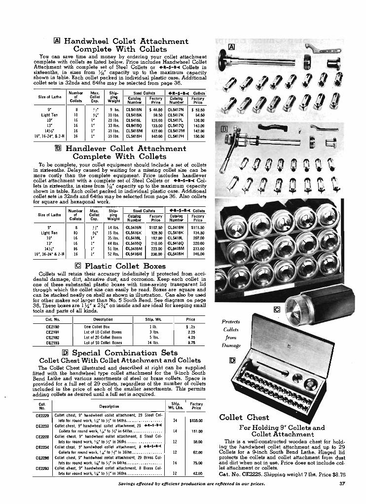
IAl Handwheel Colle.t Attach:ment Co:mplete With Colle·ts
You can save time and money by ordering your collet attachment complete with collets as listed below. Price includes Handwheel Collet Attaclunent with complete set of Steel Collets or ".-$-I-C Collets in sixteenths, in sizes from !.{6" capacity up to the maximum capacity shown in table. Each collet packed in individual plastic case. Additional collet sets in 32nds and 64ths may be selected from page 36.
Number Max. Ship- Steel Collets ".-$-I-c conets ' Size of Lathe of Collet ping Catalog Factory Catalog Factory Collets Cap. Weight Number Price Number Price ------
9' 8 J2" 9 b •. CL5415N $ 48.50 CL5417N $ 52.50 light Ten 10 %' 101bs. CL5415K 59.50 CL5417K 64.50
10' 16 I' 281bs. CL5415L 128.00 CL54171 138.00 13' 16 I' 33 lb •. CL5415Q 133.00 CL5417Q 143.00
14Yz' 16 I' 35 lb •. CL5415M 137.00 CL5417M 147.00 16', 16·24', & 2·H 16 I' 35 lb •. CL5415H 140.00 CL5417H 150.00
~ Handlever Collet Attach:ment Co:mplete With Collets
To be complete, your collet equipment should include a set of collets in sixteenths. Delay caused by waiting for a missing collet size can be more costly than the complete equipment. Price includes handlever collet attachment with a complete set of Steel Collets or ".-$-I-c Collets in sixteenths, in sizes from !.{6" capacity up to the maximum capacity shown in table. Each collet packed in individual plastic case. Additional collet sets in 32nds and 64ths may be selected from page 36. Also collets for square and hexagonal work.
Number Max. Ship- Steel Collets ".-$-I-c Collets Size of Lathe of Collet ping Catalog factory Catalog Factory
Collets Cap. Weight Number Price Number Price ---9' 8 Yo' 14lbs. CL5416N $107.50 CL5418N $111.50
light Ten 10 %' 15 lb •. CL5416K 129.50 CL5418K 134.50 10' 16 I' 35Jb •. CL5416L 197.00 CL5418L 207.00 13' 16 I' 441bs. CL5416Q 210.00 CL5418Q 220.00
14Yz' 16 I' 51 lb •• CL5416M 223.00 CL541BM 233.00 16', 16·24' & 2-H 16 I' 52 lb •. CL5416H 236.00 CL5418H 246.00
IQI Plastic Collet Boxes Collets will retain their accuracy indefinitely if protected from acci
dental damage, dirt, abrasive dust, and corrosion. Keep each collet in one of these substantial plastic boxes with time-saving transparent lid through which the collet size can easily be read. Boxes are square and can be stacked neatly on shelf as shown in illustration. Can also be used for other makes not larger than No. 5 South Bend. See diagram on page 36. These boxes are 17;(" x 2 %;" on inside and are ideal for keeping small tools and parts of all kinds.
Cal No. Description Ship. Wl Price
CE2190 One Collet Box lib. $ .25 CE2191 lot of 10 Collet Boxe. 3 lb •. 2.25 CE2192 lot of 20 Collet Boxe. 5 lb •. 4.25 CE2193 lot of 50 Collet Boxes 141bs. 8.75
IQI Special Co:mbination Sets Collet Chest With Collet Attachment and Collets The Collet Chest illustrated and described at right can be supplied
fitted with the handwheel type collet attachment for the 9-inch South Bend Lathe and various assortments of steel or brass collets. Space is provided for a full set of 29 collets, regardless of the number of collets included in the price of each of the smaller assortments. This permits adding collets as desired until a full set is acquired.
Cal Description Ship. Factory
No. WlLbL Price ---CE2220 Collet chest, 9' handwheel collet attachment, 29 Steel Col·
let. for round work, U,' to Yo' in 64th .. .................. 14 $135.00 CE2233 Collet chest, 9' handwheel collet attachment, 29 +R-S-I-<
Collets for round work, ~' to Yo' in 64ths . ..... .... ...... 14 151.00 CE2229 Collet chest, 9' hand wheel collet attachment, 8 Steel Col·
lets for round work, ~' to y.' in 16ths .... . .............. 12 58.00 CE2234 Collet che.t, 9' handwheel collet attachment, 8 +I-S-I-<
Collets for round work, ~'to y.' in 16ths .... ..... .. ..... 12 62.00 CE22tO Collet chest, 9' handwheel collet attachment, 29 Brass Col-
leis for round work, ~'to Yo' in 64ths ................ ... 14 75.00 CE2293 Collet chest, 9' handwheel collet attachment, 8 Brass Col·
lets for round work, ~'to y.' in 16th ..... ............... 12 42.00
~'(J"~ Q ~l ~
Protects
Collets
from
Damage
Collet Chest For Holding 9" Collets and
Collet Attachment This is a well-constructed wooden chest for hold·
ing the handwheel collet attachment and up to 29 Collets for a 9-inch South Bend Lathe. Hinged lid protects the collets and collet attachment from dust and dirt when not in use. Price does not include collet attachment or collets. Cat. No. CE2225. Shipping weight 7lbs. Price $8.75
Saving. effected by efficient production are rejtec;ted in our prices. 37

Step Chuck Equipment for South Bend Lathes Step Chucks are used with either the handwheel type or the
handlever draw-in chuck attachment for holdinq discs, qear blanks, and similiar round work. The construction of the step chuck is similiar to that of the reqular collets, except that it is desiqned for holdinq larqer diameters. A closer screws onto the threaded end of the lathe spindle nose and the step chuck screws into the threaded hole in the draw bar of the draw-in collet chuck attachment. As the step chuck is drawn back into
the closer by the draw-bar of the collet attachment, the three jaws of the step chuck are tiqhtened on the work by the taper inside the step chuck closer.
The work is riqidly supported and can be chucked quickly and accurately. The larqe qrippinq surface prevents distortion of thin walled parts such as tubinq, and also prevents marrinq the work.
38
!AI Closers for Step Chucks A closer is required for each size of step chuck, with exception of the 2" size which
fits directly into the collet sleeve included in the equipment of the collet attachment. Step chuck closers are made of cast iron or steel, and are threaded to fit the spindle nose of the lathe.
Catalog Size Lathe
Takes Step Shipping F actory Number Chuck Sizes Weight Price
CL6309NK 9 H & 3" and 4" 3lbs. $ 5.75 CL6311NK Liqhl Ten 5 '" and 6 " 5 lb • . 9.00
CLS309LQ 10" and 13'
3 " and 4" 4 lb •. 8.50 CL6311LQ 5 11' and 6# 6 lb • . 11.50
CL6309MH 14 ~H, 16", 3 .... and 4" Sib • . 9.50 CL6311MH 16-24' & 2-H 5" and 6 " 7 lb •. 13.25
I§) Finished Step Chucks Finished step chucks have 4 to 6 steps which are finished to the diameters indica·
ted in table below. Steps are l1'ij" deep, and may be remachined as required to any larqer diameter up to the maximum capacity of the step chuck.
Size Nominal Diameters Ship . Cat . F actory Lathe Size of Stepa Wt. No . Price
2" 2", 1 "'11', 1 ~"', 1" 2 lb • . CE5900· $11.00 3 ' 3 ", 2 ~", 2 Yz"', 2 }(", 2*, l ~" 3 lb • . CE5961 15.75
9' 4 ' 4 ", 3 ~"", 3 U", 3 11", 2U"', 2 3-1" Sib •. CE5962 17.25 S' 5"", 4 J.i:.II', 411', 3 Yz", 3 7(''', 3" Bib • . CE5963 19.00 6 " 6 ' ,. S ~', S', 4 ~', 4 ~", 4H 12 lb •. CE5964 21.50
2" 2", 1 ~", 1 ~', I " 3 lb • . CE59SS· I1.S0 3" 3", 2 ~', 2 ~H, 2 ~', 2H, 1 ~' 4 lb • . CE5966 15.75
Liqhl fen 4" 4", 3 ~', 3 ~', 3", 2 ~', 2 ~" 6 lb •. CE59S7 17.50 S" S", 4 ),i", 4', 3 ~", 3 ~', 3 " Bib • . CES968 19.50 6 ' 6", S ~", S', 4 ~H, 4 ~', 4" 12 lb • . CE5969 22.25
2 ' 2 "', 1 ~4.H, 1 ~", 1· 4 lb •. CE5975· 12.25 10", 13' , 14 ),iH, 3 " 3H, 2 ~", 2 ),i', 2 J~H, 2 ', 1 ),i" 4lbs. CE5976 17.00
16", 16-24", 4H 4", 3 Yz", 3 ~1t, 3 ", 2 ~", 2 ~'" Sib •. CE5977 19.00 & 2-H S" 5 .11', 4 }ill', 4", 3 }i", 3 ~"', 3" 9 lb • . CE5978 21.25
6 " 6H, S ),i', S", 4 ~H, 4 ~', 4H 13 lb •. CE5979 22.75
~his step chuck: fita directly into collet sleeve and does not require a closer.
[g Step Chuck Blanks Extreme preCision can be attained by mountinq a step chuck blank in the closer of
the lathe on which it is to be used and machining either multiple steps or a sinqle cavity to receive the work. The cavity obviously will run dead true and should chuck the work to be machined with perfect concentricity.
Step chuck blanks are made in various sizes havinq a maximum capacity of 2", 3", 4", 5 ' ,and 6H respectively. The 2" size fits directly into the collet sleeve and does not require a closer, but all other sizes must be used with a closer of required size.
Nominal Max. Shipping Catalo'1 F a ctory Size Lathe Size Cap. Weight Number P ric e
2" 2H 21bs. CE591S· $ 8 .25 3 " 3" 31bs. CES917 11.25
9' 4 ' 4" Sib • . CE5918 12.75 S" S" Bib • . CE5919 14.50 6" 6" 12 lb • . CE5920 17.25
2" 2H 31bs. CE593S· 8 .75 3H 3' 4 lb • . CE5937 11.50
Liqhl Ten 4 ' 4H 61bs. CE5938 13.25 SH S" Bib • . CE5939 15.25 6H 6H 12 lb •. CE5940 17.75
2 ' 2H 4 lb • . CE592S· 9 .50 10", 13H, 14 ),i', a" 3 " 4 lb • . CE5927 12 .50
16", 16-24H, 4 ' 4 " Sib • . CE5928 14.50 & 2-H SH S' 91bs. CE5929 IS.75
S" 6" 13 lb • . CE5930 18.50
*This step chuck fita directly into collet sleeve and does not require a closer.
You wouldn't drive f plou/Zh hor6e on a race track-why put a heavy duty machine on a precision jobT
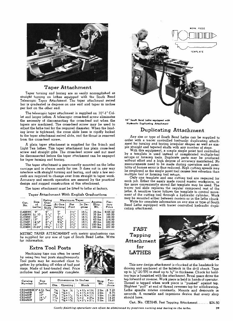
Taper Attach:ment Taper turning and boring are as easily accomplished as
straight turning on lathes equipped with the South Bend Telescopic Taper Attachment. The taper attachment swivel bar is graduated in degrees on one end and taper in inches per foot on the other end.
The telescopic taper attachment is supplied on 10' -1' Collet and larger lathes. A telescopic cross-feed screw eliminates the necessity of disconnecting the cross-feed nut when the tapers are machined. The cross-feed screw may be used to adjust the lathe tool for the required diameter. When the binding lever is tightened, the cross slide base is rigidly locked to the taper attachment swivel slide, and the thrust is removed from the cross-feed screw.
A plain taper attachment is supplied for the 9-inch and Light Ten lathes. This taper attachment has plain cross-feed screw and straight gibs. The cross-feed screw and nut must be disconnected before the taper attachment can be engaged for taper turning and boring.
The taper attachment is permanently mounted on the lathe carriage and is always ready for use. It does not in any way interfere with straight turning and boring, and only a few seconds are required to change over from straight to taper work. Accuracy and smooth operation are assured by the practical design and rugged construction of this attachment.
The taper attachment must be fitted to lathe at factory.
Taper Attachment With English Graduations
Size Swing Maxitnu:rn Taper
A~prox. Fae-Cat. Over No. of Cross At One Per In De- hip . tory
Lathe Slide Setting Foot greu Wt. Price --- --- --------- ------ ---Cl428NK 9" 5 ' 7 ' 3 ~" lS Yo 35lbs. $105.50 Cl428NK Lt. 10 5 Ys' 7' 3 ~" lS ~ 35 lb • . 105.50 C1l545R 10' 5~' 8 ~'" 3 yz" lS Yo 40 lb • . 188.00 C1l545T 13' S' 9 ~' 3 Yo' lS Y. S5Ib •. 214.00 C1l545F 14 Yo' 81 ~,jJI 9~' 3 ~' lS ~ SOlbs. 230.00 C1l545H IS' 9 5 "" 11 Yo' 3 Yo' lS ~ 100 lb • . 257.00 .. C1l545H 16-24" 18~' 11 Yo' 3 Yo" lS Y. 100 lb •. 257.00
METRIC TAPER ATTACHMENT with metric graduations can be supplied for any size of type of South Bend Lathe. Write for information.
Extra Tool Posts Machining time can often be saved
by using two tool posts simultaneously. Tool posts may be mounted close together by grinding off sides of tool post rings. Made of heat-treated steel. Price includes tool post assembly complete.
Catalog Size Ditnensions In Inches Number Lathe
Dia. Opening Block
CE24S0NK 9' & Lt. ren .~ I~ % Yo I. % 1 ~ % 1% CE2450R 10' I!.{, I~ % 1 J.. % 1% :a:l Y2 CE2450T 13' 1~ It...6 x I J
" % xl ~ %l Ys CE2450F 14 Yo' 1 I !-{a ' !-{a % 1 ~ Y. %2 %2~ CE2450H IS" l Y. '~ %1 ~ V. %2 J4' %2 ~
Ship. Wt.
2lbs. 2lbs. 3 lb •. 4 lb • . 5 lb •.
Fae-tory
.Price --$ 7.25
8.7 5 00 1l.
14.25 IS. 25
10' So"th Bend Lathe eq"ipped with Hydraulic Duplicating AHachment
WORK PIECE
[Ooum> ~
TEMPLATE
Duplicating Attach:ment Any .size or type of South Bend Lathe can be supplied to
order Wlth a tracer controlled hydraulic duplicating attachment for turning and boring irregular shapes as well as simple straight and tapered shafts with any number of steps.
With this equipment, a simple single point tool controlled by a template is used instead of complicated multiple-tool set-ups or forming tools. Duplicate parts may be produced without effort and a high degree of accuracy maintained. No measurements need to be made during operation and possibility of human error is thus reduced. High cutting speeds may be employed as the single point tool causes less vibration than multiple tool or forming tool setups.
Only one template and one cutting tool are required for each job. Either the easily made round master workpiece or the more conveniently stored flat template may be used. The tracer tool slide replaces the regular compound rest of the lathe. A sensitive tracer follows the template to control movement of the cutting tool through a hydraulic cylinder. Work may be mounted either between centers or in the lathe chuck.
Write for complete information on any size or type of South Bend Lathe equipped with tracer controlled hydraulic duplicating attachment.
FAST Tapping
Attach:ment for
LATHES
This new design attachment is chucked at the headstock for driving and anchored at the tailstock in the drill chuck. Taps up to ~'-20 TPI in steel up to ~' in thickness. Chuck for holding taps is furnished with the attachment. Bevel gears drive the tap forward or reverse. Work piece is held in hands of operator. Thread is tap,ped .when work piece is "pushed" against tap. Slightest "pull" at end of thread reverses tap for withdrawing. Lathe spindle rotates constantly. Mounts and demounts in seconds. A versatile and ingenious device that every shop should have.
Cat. No. CE3145. Fast Tapping Attachment. .. . . . . $24.50
Costly finishing operatio .... can often be eliminated by precision turning and boring in the lat"". 39
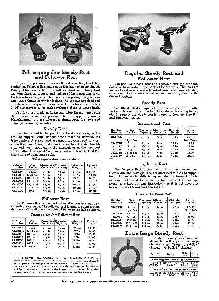
Telescoping Jaw Steady Rest and Follower Rest
To provide quicker and more efficient operation, the Telescoping Jaw Follower Rest and Steady Rest have been developed. Principal features of both the Follower Rest and Steady Rest are wrenchless adjustment and locking of the telescoping jaws. Each jaw has a large knurled knob for adjusting the jaw position, and a thumb screw for locking. An ingeniously designed double acting compound screw thread provides appro:rimately 3 /16" jaw movement for each revolution oLthe adjusting knob.
The jaws are made of brass and slide through precision steel sleeves which are pressed into the supporting frame. Manufactured to close tolerances throughout, the jaws and other parts are replaceable.
Steady Rest The Steady Rest is clamped to the inside bed ways, and is
used to support long, slender shafts mounted between the lathe centers. It is also used to support the outer end of a bar or shaft in such a way that it may be drilled, bored, reamed, etc., with tools mounted in the tailstock or in the tool post of the lathe. The top of the steady rest is hinged to facilitate inserting and removing shafts.
Telescoping Jaw Steady Rest
Catalog Size Mazirnun'\ Minil1\um. Shipping Factory ~umber Lathe Capac:ity Capacity Weight Price
-CL2400N 9 inc:h 3 in. ~in . 11lbs. $ 14.SO CL2400K Light Ten 3 in. ~in. 11 lb •. 15.75 CL2400R 10 inch 3 in. ~in. 13 lb •. 18.00 CL2400T 13 inch 3~ in. ~in. 21 lb •. 22.00 -CL2400F 14 ~inch 4~in. \.it in. 28 lb • . 25.75 CL2400H 16" &: 2·H 4~ in. ~in. 30 lb •. 28.SO CL2400V 16-24" 4~ in. ~in. 47 lb • . 37.SO
Follower Rest The Follower Rest is attached to the lathe carriage and trav
els with the carriage. The follower rest is used to support long, slender shafts while being machined between the lathe centers.
Telescoping Jaw Follower Rest
Catalog Size Maximum. Minimum Shipping Fac:tory Number Lathe Capacity Capacity Weight Price
CL2395N 9 inch 2 in. ~ in . 7 lb •. $ 9 .25 CL2395K Light Ten 2 in. 1M in. 7 lb •. 10.50 CL2395R 10 inch 2~in. \.it in . 9 lb •. 11.S0 CL2395T 13 inch 3X( in. ~in. 11 lb •. 13.00 CL2395F 14 ~inch 4X( in. ~ in. 15 lb •. IS.SO CL239SH IS" &: 2.H 4X( in. ~in. 17 lb •. 17.00 CL2395V 16-24" 4X( in. 'M in. 21 lb.'. 23.25
PRICES IN THIS CATALOG are net f .o .b. South Bend. Indiana unless otherwise stated. In accordance with our established policy prices are subject to change without notice and accord. inqly prices herein are not necessarily those at which deliveries will be made at any future date because we reserve the right to invoice future deliveries at prices in effect at that til't\e.
Regular Steady Rest and Follower Rest
The Regular Steady Rest and Follower Rest are ruggedly designed to provide a rigid support for the work. The jaws are made of cast iron, are machined all over and have adjusting screws and lock screws for setting and securing them in the desired position.
Steady Rest The Steady Rest Clamps onto the inside ways of the lathe
bed and is used for supporting long shafts, boring spindles, etc. The top of the steady rest is hinged to facilitate inserting and removing shafts.
Requ1ar Steady Rest
Catalog Size Mazimum Minimum Shipping Factory Num.ber Lath. Capac:ity Capacity Weight Price
CLll77N 9 in. 3 in. X( in. 10 lb •. $ 9.75 .... .. .. . . . Light Ten . ..... ... ... ..... . Not Mad. CLll77R 10 in. 3 in. X( in. 11 lb • . 14.25 CLll77T 13 in. 3~' in. % in. 19 lb • . 18.00 CLll77F 14~in. 4~ in. % in. 27 lb • . 22.00 CL1l77H 16' &: 2-H 4~ in. :Y8 in. 29 lb •. 24.75 CLll77V 1S-24 in. 4~ in. ~, jn. 47 lb • . 33.75
Follower Rest The Follower Rest is attached to the lathe carriage and
travels with the carriage. The Follower Rest is used to support iong, slender shafts while being machined between the lathe centers. Slots used for attaching follower rest to carriage permit attaching or removing quickly as it is not necessary to remove the screws from the saddle.
Catalog Number
CL13S3N .... ... .. CL13S3R CL13S3T CL1353F CL1353H CL13S3V
Reqular Follower Rest
Size Maxirnum Minimum. Shippinll F actory Lathe Capaci.ty Capacity Weight Price
9 in. 2 in. ~ in . 4 lb •. $ 6.S0 Light Ten ... . .. . ..... ... ... Not Made 10 in. 2 ~in. ~in. Slb •• 9.75 13 in. 3 X( in. ~in. 9 lb •• 11.00 14 ~in. 4 X( in, ~ in. 12 lb •. 13.00
16" &: 2-H 4 X( in. ~in. 13 lb •. 14.25 lS·24 in. 4 X( in. ~iD . 18 lb •. 2O.SO
Extra Large Steady Rest Similar to steady rests described
above, but with capacity for large diameter work. Takes from 4-3/ 4" diameter to 10-3/ 4" diameter.
Cat. No.1 Lathe I Ship. I P . Wt. rice
40 It is easy to imitate appearance-dlfficult to equal performance.

Combination Double Tool Slide This combination Handlever and Screw Feed Double Tool
Cross Slide is mounted on the saddle cross slide dovetail in place of the compound rest asSembly. It does not interfere with the power longitudinal carriage feeds. The power cross-feed can be used by removing the handlever and replacing it with the cross-feed screw. Cross-feed nut is supplied for either English or metric pitch thread. Adjustable stops limit the movement of the cross slide in either direction, in or out. Handlever can be used on either side.
This cross slide has front and back square tool blocks in which V.6" square cutter bits can be mounted. T-slots in the cross slide base permit adjusting the positions of the tool blocks. The front tool block takes two cutter bits, and the back tool block takes one cutter bit. Tapered wedges and thumb screws provide adjustment for the height of cutter bits.
Cat. No. Size Lathe Cro .. -Feed Ship. Wt. Price*
CL2030N 9" 3SIb •. $104.00 CL2030K Lillht ren ENGUSH 37 lb •. 110.00 CL2030R 10" 4SIb •. 123.00
CL2030NME 9" 3S lb • . 104.00 CL2030KME Lillht ren METRIC 37 lb • . 110.00 CL2030RME 10" 45 lb •. 123.00
*Can be .upplled I ... handley., at 10_ prie ... Write for Information.
Patented
Square Turret Tool Block for Double Tool Cross Slide
The Square Turret Tool Block shown above is designed for use on the screw feed double tool cross slide. It cannot be used on the compound rest cross slide.
Four cutting tools can be mounted in the turret tool block. The turret indexes accurately, permitting each . tool to be use~ in seq.uence for rough turning, finish turning, facing, bonng, cutting'off, or other operations as required. A quick acting lever locks the turret securely in each of the four positions. Rocker adjustment is provided for adjusting the height of the cutting edge of each tool.
Square Turret Tool Block .for Double Tool Slide
Catalo11 Size of Size Take. Ship. Factory Number Lathe Square Toola W.illht Price
CL3376NR 9" and 10" 3" %" ]1; ~8" 10 lb • . $41.50
CL3376K Lillht ren 3" %" x %" 11 lb • . 41.50
CL3376T 13" 3" }s"" X %" 20 lb • . 51.00
CL3376H IS" & No. 2.H 4" %' x %4' 28 lb • . 85.00
Screw Feed Double Tool Cross Slide for 13" and 16" South Bend Lathes
This cross slide fits on the saddle dovetail in place of the compound rest assembly. The cross-feed may be operated by power through the friction clutch in the apron, as well as by the cross-feed handwheel. A large diameter micrometer graduated collar permits adjusting the cutting tools with extreme p~ecision. <;ross-feed screw and graduations are supplied in elther English or metric system.
Adjustable stops are provided for locating the position of the front and rear tools for repetitive operations. See page 50 for four-position stop. The front tool block takes two square cutter bits and the back tool block takes one square cutter bit. Tapered wedges are provided for adjusting the height of the cutter bits. T-slots in the cross slide base are provided for adjusting the position of the tool blocks. Should be ordered with the lathe.
Cataloll Size ero •• - Size Shippinll Nuznber Lathe F .. d Bit W.illht
CL2027T 13" ENGUSH l1o" sq. 60 lb •. CL2027H IS" %" sq. 9SIb •.
CL2027TME 13" METRIC '"," sq. 60 lbs. CL2021HME IS" %" sq. 95 lb •.
Patented
Square Turret Tool Block for COlllpound Cross Slide
Factory Price
$151.00 110.00 .
151.00 110.00
The Square Turret Tool Block shown above is designed for use on the base of the compound cross slide. It cannot be used on the double tool cross slide.
Four cutting tools can be mounted in the turret tool block. The turret indexes accurately, permitting each tool to be use? in seq.uence for rough turning, finish turning, facing, bor:mg, cutting-off, or other operations as required. A quick acting lever locks the turret securely in each of the four positions. Rocker adjustment is provided for adjusting the height of the cutting edge of each tool.
Square Turret Tool Block for Compound CroBS Slide
Cataloll Size of Size Takes Shippinll Factory Number Lathe Square Tools Weillht Price
CL3375N 9" 3" %" x %" 13 lb •. $46.00 CL3375K Lillht ren 3" ~811' ]I: % .. 14 lb •. 48.50 CL337SR 10" 3" %" :z: %* 15 lb •. 52.00 CL3375T 13" 3" % .... x ~811' 24 lb • . 58.50 CL3375F 14 ~211' 4" %* x %1I' 3SIb •. 84.00 CL3375H IS" and 16-24" 4" ~8" x %'" 40 lb •. 91.00
For a better bu}-buy South Bend. 41

Handlever Bed Turret for 9", 10", and 13" South Bend Lathes
The Handlever Bed Turret mounts on the inside bed ways and can be locked in position at any point along the length of the bed. The turret head indexes automatically when the feed lever is pushed to the extreme right. Each face of the turret has an independently adjustable feed stop screw which accurately regulates the length of the cut. Ram lock is provided.
Accurate indexing of the turret head (within plus or minus . 000S" measured 4" from turret face) is assured by the use of hardened, ground, and superlmished index pin which operates in heat-treated steel bushings.
The 'effective feed of the turret slide is 4". Center of turret hole to top of turret slide 1 Yz". Takes standard turret tools with %" diameter shank· . Distance between opposite flats on turret head is 4Ys". When turret is ordered separate from lathe. the purchaser must assume the responsibility of fitting turret to lathe and boring turret head. .
Catalog Size Shipping Factory Number Lathe Weigh~ Price
CLlSllN g" 76 lb • . $273 .00 CLlSllK Light Ten 76 lb • . 280.00 CLlSllR 10" 8 3 lb •. 28S.00 CLlSllT 13" 130 lb • . 308.00
· Can be supplied to order_ wi th ~ ... holes in turret face. No extra c harge.
Handlever Turret (Tailstock Type) for 9", 10", and 13" South Bend Lathes
This handlever turret is mounted on the lathe bed in place of the tailstock. The turret head has six holes for tools with %" diameter shanks. Adjustable stops are provided for each of the six turret holes. The turret head is geared to the stop roll so that the stop is brought in line with each stop screw as the corresponding tool in the turret head is revolved to the working .position. The indexing mechanism is of high carbon heattreated steel. Index lock releases automatically at the end of the return movement of the turret slide. The turret head is revolved by hand. The maximum length of stroke is 3 ;!4 inches. When ordered separate from lathe, purchaser must assume the responsibility of fitting and boring.
Cat. No. Size Lathe Shipping Weight Price
CL2045N g" SO lb •. $llS.00 CL2045K Light Ten 50 lb • . 123.00 CL2045R 10" 60 lb • . 134.00 CL2045T 13 " 90 lb •. l S1.00
Bed Turret for 16" Lathe The Hand Feed Turnstile Bed Turret is mounted on the in
side bed ways of the lathe. The large turnstile is provided for hand operated turret slide feeds. No power feed is available.
The turret head is hexagonal in shape, having six accurately machined faces. It indexes automatically when the turret slide is returned to the starting position. An individual feed stop is provided for each face of the turret. The stop accurately regulates the length of the cut. The turret head may be back indexed or spun when it is desired to skip tool positions .
Accurate indexing (within plus or minus .000S" measured 4" from turret face) is assured by the use of a hardened, ground, and superfinished index pin which operates in heat-treated steel bushings. The indexing bushings are replaceable. The main central bearing is tapered for adjustment. The turret head is locked securely in position by a substantial binder_ The turret slide has tapered gibs on both sides which provide adjustment for wear and alignment. Ram lock is provided.
Effective feed of turret slide S Ys" . Center of turret hole to top of turret slide 2Yz". Takes standard turret tools with 1 Yz' diameter shank. Distance between opposite turret flats is 9 %". When turret is ordered separate from lathe, the purchaser must assume the responsibility of fitting and boring.
Cat. No. CL1917H. Hand Feed Turnstile Bed Turret for 16" South Bend Lathe. Ship. wt. SOSlbs. Price .. . . . . ... .. . $683.00
Bed Turrets for 13" Lathe This turret for 13" lathe can be supplied with power and
hand feed or with turnstile hand feed only. It has independent feed trip and stop for each of the six turret faces. Effective feed of turret slide is 6Yz". Quick change box of lathe provides 144 power turret feeds .0006" to .1093". Lever shift gears in turret apron provide quick selection of fast, intermediate or slow feeds. Direction of feed is reversed by changing gears in turret apron. Turret head revolves on a precision ball bearing and has six 1" diameter holes for tools. Turret head indexes and locks automatically on the return stroke of the turret slide. Turret ram lock is provided. Clearance from center of tool hole to top of turret slide is 1 Yz". When ordered separate from lathe, customer must assume responsibility of fitting and boring, however the design of this turret is such that relatively little fitting is required for either the power feed type or hand feed type. Mounting instructions furnished with each turret.
Cat. No. CL1917T. Hand Feed Turnstile Bed Turret for 13' South Bend Lathe. Approx ship . wt. 3461bs. Price . .. ... . . $495
Cat. No. CL2620T. Power Feed Turnstile Bed Turret for 13" South Bend Lathe. Approx. ship. wt. 4141bs. Price .. . .. . . $698
42 A drop of oil costs so little-sa.es so much.

Duplex Turret Tool Holder With this Duplex Turret
Tool Holder, two tools can be mounted on one face of the turret head . Shank of tool holder fits into turret head and tools are mounted in two holes in holder . Lever on holder is used to turn each tool into operating position as required. Adjustable stops position tool with sufficient accuracy for most drilling, reaming, or tapping operations.
Cat. Shank Size Hole Size No. Dia. Length Dia. Length ------ ---
CE2666 ~iA' I~" %" ' /" /. CE2667 ~.IP I ~" %11' ~" CE2668 I " I ~" %" ~Jr
CE2669 I ~" 2 Ys" I" II"'''
Ship. Wt . Pounds
4 6 8
10
Pneumatic Bar Feed
Factory Price
$29.00 30.00 31.00 42.00
This Pneumatic Bar Feed unit takes a twelve foot bar of stock, any shape or size, up to the maximum capacity through the bar feed cylinder, provided the bar is no larger than the hole through the lathe spindle or collet. Air pressure forces the stock forward instantly when the collet or chuck is opened. The stock is held firmly against the stop until the collet is closed.
Low air pressure is required for operating the pneumatic bar feed unit. (Price does not include air compressor). Shipped direct from factory in New York.
Cat. No. CEI88l. Lipe Pneumatic Bar Feed Unit, I ' maxi-mum bar capacity. Ship. wt. 385 lbs. Price . . $285.00
Cat. No . CEI882. Lipe Pneumatic Bar Feed Unit, 2" maxi-mum bar capacity. Ship. wt. 410 Ibs. Price . . ....... . $295.00
Indexin g Attachment for 10" Lathe Headstock
With this attachment the lathe spindle can be accurately indexed for fluting, splining, graduating, crossdrilling, and similar operations. Changeable index wheels are attached to the left end of the spindle, leaving the spindle nose free for mounting chucks, face plates, or other work holding fixtures. The index wheels do not interfere with work passed through the headstock . A spring latch index pin is rigidly attached to the headstock and engages the index wheel to position the spindle. The equipment includes eight index wheels having 45, 56, 50, 64, 72, 80, 84, and 100 divisions respectively. This attachment should be ordered with the lathe and fitted at the factory. It cannot be used with a collet attachment.
CL2505L. Indexing Attachment for 10"-1 " Collet Lathe. Shipping weight 30 Ibs. Factory Price . . . . . $115.00
Tailstocks for Sou th Bend T u rret Lath es
Prices of South Bend Turret Lathes do not include tailstock. Standard set-over type tailstock illustrated above can be supplied to order. Tailstock mounts on the lathe bed, in place of the turret, for machining work between ·centers. Spindle is graduated and is fitted with a 60° hardened center. Tailstock has set-over for taper turning. This unit should be ordered with the lathe and fitted at the factory .
Catalog Size Size Shipping Factory No. Lathe Center Weight Price
CL2036N 9 " No. 2 M.T. 22 lb • . $ 43.50 CL2036K Light Ten No.2 M.T. 22 lb • . 60.00 CL2036R 10" No. 2 M.T. 42 lb • . 76.00 CL2036T 13" No. 3 M.T. 90 lb • . 137.00 CL2036P No. 2·H No.3 M.T. 133 lb • . 171.00
Compound Rest Cross Slides for Sout h Bend Turret Lat hes
The compound rest type cross slide can be supplied for use on the saddle cross slide dovetail of any South Bend Turret Lathe in place of the double tool cross slide. This compound rest is the same as is regularly supplied with the corresponding size of lathe.
Price includes compound rest top, swivel, and base assembly complete with tool post. Cannot be used with double tool slide. When this unit is required, it should be ordered with the lathe and fitted at the factory.
Cat. No . Size Lathe Ship. Wt. Factory
Price
CL2200N 9" 13 lb •. S 38.50 CL2200K Light Ten 14 lb • . 39.50 CL2200R 10" 15 lb •. 63.00 CL2200T 13" 30 lb • . 98.00 CL2200P 2-H 50 lb •. 125.00
Total costo! work produced includesJirst cost 0/ equipment, maintenance, and interest ora i"vestntent. 43

Spindle Nose Thread Protector The threads of the lathe spindle nose should be protected
against accidental damage at all times. When a lathe chuck or face plate is not in use, the Spindle Nose Thread Protector shown above should be used. Price includes spanner wrench for removing thread protector from spindle nose thread.
Catalog Th .... d S ize NUInber Size Lath.
CL3515NK I W -a 9 " & liqht Ten
CL3515LT 2 ~'"-a 10" & 13"
CL3515FH 2 W -,6 14 ~", 16", 16-24" &2·H
Swiveling Machine Handles
Swivel type machine han· dles are standard equipment on 10"-1 ' collet and larger South Bend Lathes. They can be supplied in lieu of the reg· ular solid machine handles
Shippinq Factory Weiqht P rice ,
2 lb • . $4.15
3 lb • . 5.95
4 lb • . 8.95
for the 9 ' and Light Ten Lathes, The swivel handle is made in two parts, having an outer sleeve which revolves on a spindle. When swivel machine handles are wanted in lieu of the solid machine handles, they must be specified when lathe is ordered.
CL2605NK, Swiveling Machine Handles for apron handwheel, cross-feed knob, and tailstock handwheel in lieu of regular machine handles on 9" or Light Ten Lathes. Price ...... $1.95
Motor Belt Guard for 9" Bench Lathe This guard is designed
to enclose the motor pul· ley, motor V·belt, and countershalt drive pulley ' of 9-inch Horizontal Motor Driven Bench Lathes. It can be used with any 9-inch Horizontal Motor Drive Unit made since Feb. 1940. Guard is attached to the motor drive frame by a cap screw or bolt and a dowel pin. Frame must be drilled for pin and bolt or tapped for screw.
CL288S. Motor Belt Guard for 9 " Horizontal Motor Drive with % h.p. or ~ h.p. motor. Ship. wt. 26lbs. Price . ... $12.00
CL2886. Motor Belt Guard for 9" Horizontal Motor Drive with 72 h.p. motor. Ship. wt. 27 lbs. Price ............ $14.25
Lathe Mandrels For machining work mounted between lathe centers. Made of
steel and properly carburized, hardened and ground for maxi· mum durability. Large center holes provide substantial bear· ings on centers. Mandrels taper .006" per foot and are slightly undersize at small end for easy starting in standard holes. Flat for lathe dog is milled on each end. Nominal size of each mandrel is stamped on large end.
Catalog D ialneter Total Ship. Wt. Factory NUJnber Inch .. Lenqth.In. Pound. Price
CE3620 ~ 3 ~ I $2.65 CE36Z1 'M 4 I 2.90 CE36ZZ a/
7 8 4 ~ I 3. 15 CE36Z3 '.10 4 ~ 1 3 .45 CE36Z4 % 5 I 3 .65 CE36Z5 ~ 5 ~ I 3 .10 CE36Z6 % 5 % I 3.80 CE38Z1 'H. 5 ~ 2 4.00 CE36Z8 ~ 6 2 4. 15 CE3629 ,~ 6 ~ 2 4.30 CE3630 }i 6 % 2 4.45 CE3631 U ' ." 6 ~ 3 4.60 CE3632 I 1 3 4.15
SECTION 0,. GIiOUND TMIUAO scuw
Hardened and Ground Thread Screws for Co:mpound Rest Cross Slides
Cross·feed Screws and Compound Rest Screws with hard· ened and ground English pitch threads can be supplied in lieu of regular screws on 10" and larger South Bend Lathes. Prin· cipal advantages of the hardened and ground thread .screws are smoother operation and longer life. Prices below apply only when hardened and ground thread screws are specified when lathe is ordered and they can be supplied in lieu of regular screws when lathe is assembled at the factory.
Cross-Feed and Compound Rest Screws with Hardened and Ground Thread in Lieu of Regular Screws
Reqular Croae·F .. d Taper Attachment Crou· Fe.d
Cat. No . S;"'e Lathe P rice Cat. No. Size Lath. Price
CLZ032L 10" $12.15 CLZI98L 10" $1 4.55 CLZ03ZT 13" 21.75 CLZI98T 13" .24.50 CLZ03ZF 14 ~" 23.15 CLZI98F 14 ~" 26.15 CL2032H 16" & 16·24" 24.50 CL2198H 16" & 16-24" 21.35
CL2222T. Hardened and ground thread cross·feed screw in lieu of regular screw for 13" lathe screw feed double tool cross slide . . . . . . . . . . . . . . . . . . . . . . . .......... $17.00
CL2222H. Hardened and ground thread cross·feed screw in lieu of regular screw for 16" lathe or 2-H turret lathe screw feed double tool cross slide . . . . . . . . . . .... . . . ...... $19.00
~. Center
Knock-out Bar
For removing headStock center and sleeve from spindle. Made of steel, with knurled handle and brass bushing.
Cataloq Size Outside Total Ship. ' Factory Number Lath. Dia. Length Weight Price ---
CEI475NK 9 " & Lt. Ten ~" 16" 4 lb • . $1.50 CEI41SL 10"·1" Col. 1%" 11l-M" 1 lb • . 2 .25 CE147SQH 13", 14 %", 16",
16-24", & 2·H . 1% " 2B \{," 1 lb •. 3 .50
44 Every too/room lathe should be equipped with a South Bend Internal Grinding Attachment. See page 49.
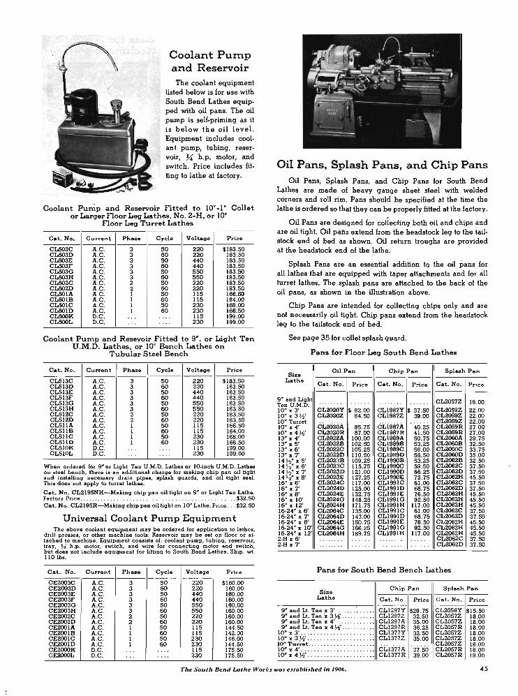
Coolant Pump and Reservoir
The coolant equipment listed below is for use with South Bend Lathes equip. ped with oil pans. The oil pump is self·priming as it is below the oil level. Equipment includes cool· ant pump, tubing, reser· voir, 7.{ h.p . motor, and switch. Price includes fit· ting to. lathe at factory.
Coolant Pump and Reservoir Fitted to 10"·1" Collet or Larger Floor Leg Lathes, No. 2·H, or 10'
Floor Leg Turret Lathes
Cat. No. Current Ph ... Cycle Voltag. Price
CL503C A.C. 3 SO 220 $183.50 CL503D A.C . 3 60 220 183.50 CLS03E A.C . 3 SO 440 183.50 CL503F A.C . 3 60 440 183.50 CL503G A.C. 3 SO 550 183.50 CLS03H A.C. 3 60 550 183.50 CL502C A.C . 2 50 220 183.50 CLS02D A.C . 2 60 220 183.50 CL501A A.C . 1 50 liS 166.50 CLSOIB A.C . 1 60 liS 164.00 CLSOIC A.C. 1 SO 230 168.00 CLSOlD A.C. 1 60 230 166.50 CL500K D.C . .. . . .. . liS 199.00 CL500L D.C . ... .. .. 230 199.00
Coolant Pump and Resevoir Fitted to 9", or Light Ten U.M.D. Lathes, or 10" Bench Lathes on
Tubular Steel Bench
Cat. No. Current Phase I Cycle Voltage Price
CL513C A.C . 3 SO 220 $183.50 CL513D A.C . 3 60 220 183.50 CL513E A.C . 3 SO 440 183.50 CL513F A.C . 3 60 440 183.50 CL513G A.C. 3 SO 550 183.50 CL513H A.C . 3 60 550 183.50 CLS12C A.C. 2 50 220 183.50 CL512D A.C. 2 60 220 183.50 CL511A A.C . 1 50 liS 166.50 CL511B A.C . 1 60 liS 164.00 CLSllC A.C . 1 50 230 168.00 CLSllD A.C . 1 60 230 166.50 CL510K D.C . ... .... liS 199.00 CLSI0L D.C . ... . ... 230 199.00
When ordered lor 9" or Light Ten U.M.D. Lathes or lO·inch U.M.D. Latbe. on steel bench, there is an additional charge for malting chip pan oil tight and installing necessary drain pipes, splash guards, and oil light seal. This does not apply to turret lathes.
Cat. No. CL2195NK-Malting chip pan oil light on 9" or Ligbt Ten Latbe. Factory Price . . . . . . . . . . . .. . . ... $32.50 Cat. No. CL2195R-Malting chip pan oil light on 10" Lathe. Price . .. $32.50
Universal Coolant PUInP EquipInent The above coolant equipment may be ordered for application to lathes,
drill presses, or other machine tools. Reservoir may be Bet on floor or attached to machine. Equipment consists of: coolant pump, tubing, reservoir , tray, U h .p. motor, switch, and wire for connecting motor and switch, but does not include equipment for fitting to South Bend L""thes. Ship. wt. 110 lb • .
Cat. No. Current Phase Cycle Voltage Price
CE2003C A.C. 3 SO 220 $160.00 CE2oo3D A.C . 3 60 220 160.00 CE2oo3E A.C . 3 SO 440 160.00 CE2003F A.C . 3 60 440 160.00 CE2oo3G A.C . 3 SO 550 160.00 CE2003H A.C. 3 60 550 160.00 CE2002C A.C . 2 SO 220 160.00 CE2002D A.C. 2 60 220 160.00 CE200lA A.C . 1 SO liS 144.50 CE2001B A.C . 1 60 liS 142.00 CE2001C A.C. 1 SO 230 146.00 CE200lD A.C. 1 60 230 144.50 CE2000K D.C. ... . ... liS 175.50 CE2000L D.C . ... .. .. 230 175.50
Oil Pans, Splash Pans, and Chip Pans Oil Pans, Splash Pans, and Chip Pans for South Bend
Lathes are made of heavy gauge sheet steel with welded corners and roll rim. Pans sh~uld be specified at the time the lathe is ordered so that they can be properly fitted at the factory.
Oil Pans are designed for collecting both oil and chips and are oil tight. Oil pabs extend from the headstock leg to the tail· stock end of bed as shown. Oil return troughs are provided at the headstock end of the lathe.
Splash Pans are an essential addition to the oil pans for all lathes that are equipped with taper attachments and for all turret lathes. The splash pans are attached to the back of the oil pans, as show~ in the illustration above.
Chip Pans are intended for collecting chips only and are not necessarily oil tight. Chip pans extend from · the headstock leg to the tailstock end of bed .
See page 35 for collet splash guard.
Pans for Floor Leg South Bend Lathes
Size Lath.
Oil Pan Chip Pan Splash Pan
Cat. No. Price Cat. No. P!'ice Cat. No . Price - ---·11----1-g" and Light Ten U.M.D. 10" x 3' 10" z 3 YS' 1011' Turret ION x 4' 10" x 4 YS' 13" z 4' 13" x 5' 13" z 6' 13" z 7' 14 ~" zs' 14 ~- x 6' 14 ~" x 7 ' 14 7'0- x 8' 1611' X 6' 16" x 7' 16" x 8' 16" z 10' 16" z 12' 16-24" x 6' 16·24" z 7' 16-24" z 8' 16·24" z 10' 16-24" z 12' 2-H z 6' 2-H z 7'
CL2020Y $ 82.00 CLl987Y $ 37.50 CL2020Z 84.50 CLl987Z 39.00
CL20ZOA CL2020R CL2022A CL2022B CL2022C CL2022D CL2023B CL2023C CL2023D CL2023E CL2024C CL2024D CL2024E CL2024G CL2024H CL2064C C.L2064D CL2064E CL2064G CL2064H
85.75 87.00
100.00 102.50 105.25 110.50 109.25 115.75 121.00 127.25 117.00 125.00 132.75 148.25 171.75 135.00 143.00 150.75 166.25 189.75
CLis87A CL1987R CL1989A CL1989B CL1989C . CL1989D CLl990B CLI990C CLl990D CLI990E CLl991C CLI99lD CL1991E CLl991G CLl991H CLl991C CL199lD CL1991E CLl991G CLl991H
40 .25 41.50 50.75 53.25 56.00 58.50 53.25 59.50 66.25 72.75 61.00 68.75 76.50 92.50
117.00 61.00 68.75 76.50 92 .50
117.oo
CL2057Z 18.00 CL2059Z 22 .00 CL2059Z 22.00 CL2059Z 22.00 CL2059R 27 .00 CL2059R 27.00 CL2060A 29.75 CL2060B 32.50 CL2060C 33.75 CL2060D 35.00 CL2062B 32.50 CL2062C 37 .50 CL2062D 37.50 CL2062H 45.50 CL2062C 37.50 CL2062D 37.50 CL2062H 45 .50 CL2062H 45.50 CL2062H 45.50 CL2062C 37.50 CL2062D 37.50 CL2062H 45.50 CL2062H 45.50 CL2062H 45.50 CL2062C 37.50 CL2062D 37.50
Pans for South Bend Bench Lathes
Size Chip Pan Splash Pan
Lathe Cat. No. Price Cat. No. Price
9" and Lt. Ten I 3' ...... . . .. . . . CLI297Y $29.75 CL20s6Y $15.50 g" and Lt. Ten x 3 YS' .. CLI297Z 32.50 CL2057Z 18.00 g" and Lt. Ten z 4' ........... .. CLI 297A 35.00 CL2057Z 18.00 g" and Lt. Ten z 4 YS' . ..... . ..•• CLI 297R 36.25 CL2057R 18.00
ION I 3' .. . .. . ....... . . . ..... •. CL1377Y 32.50 CL2057Z 18.00 10" z 3 YS' ... .. .. .. .......... .. CLI377Z 35.00 CL2057Z 18.00 10" Turret ... . . ... . .. . .. . .. . ...
cLi:iiiil. ·37.50 CL2057Z 18 .00
10" z 4' .. .... ... . . ... . .. .. .... CL2057R 18.00 10" x 4 YS' .. .. . .. . . ... . . . CL1377R 39.00 CL2057R 18.00
The Sout h Bentl Lathe Works wa.' estaIJlished in 1906. 45
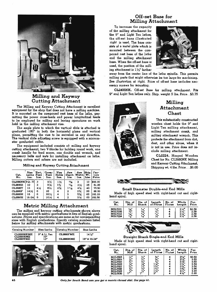
Milling and Keyway Cutting Attachment
The Milling and Keyway Cutting Attachment is excellent equipment for the shop that does not have a milling machine. It is mounted on the compound rest base of the lathe, permitting the power cross-feeds and power longitudinal feeds to be employed for milling and boring operations on work held in the milling attachment vise.
The angle plate to which the veJ1ical slide is attached is graduated 180° in both the horizontal plane and vertical plane, permitt1ng the vise to be swiveled in any direction. The vertical slide adjusting screw is equipped with a micrometer graduated collar.
The equipment included consists of: milling and keyway cutting attachment, two V-blocks for holding round work, one crank handle for feed screw, one double end wrench, and necessary bolts and nuts for installing attachment on lathe. Milling cutters and arbors are not included.
Milling and Keyway Cutting Attachment
Size Vert. c...,..- ViM Jaw Jaw Ship. Fac-Cat. Lathe Feed F_d Holda Depth Width Wt. tory No. Ins. Ina-. Ina. Ina. Ina. Ina. Lb.. Price -----------------
CL2680NK !l-U. 10 3 5}i 1 ;2 ,~ 3 13 $49.00 CL2680R 10 3 5 7i I~ ,~ 3 ;2 25 61.00 CL2680T 13 4~ 83-l 2 7i I' !-M 4 7i 40 75.50 CL2680F 14;2 6 10 4 2 5 ~ SO 66.50 CL2680H 16 6 10;2 4 2 5~ 65 102.50 CL2680H 16-24 6 10;2 4 2 5 ~ 65 102.50
Metric Milling Attachment . The milling and keyway cutting attachments shown above
can be supplied with metric graduations in lieu of English graduations. Prices and specifications are same as for corresponding sizes with English graduations. Specify catalog numbers listed below for milling attachments with metric graduations.
Catalog Number Size Lathe Catalog Number Siae Lathe
CL2680NKME 9'" ." Lt. Ten CL2680FME 14;2' CL2680RME 10" CL2680TME 13' CL2680HME 16' " 16-24'
Off-set Base for Milling Attachment
To increase the capacity of the milling attachment for the 9 ' and Light Ten lathes, the off-set base illustrated right is used. The base consists of a metal plate which is mounted between the compound rest base of the lathe and the milling attachment base. When the oH-set base is used, the position of the milling attachment is 172" farther away from the center line of the lathe spindle. This permits milling parts that might otherwise be too large for machining. See illustration at right. Price of oH-set base includes necessary screws for mounting.
CL2408NK. OH-set Base for milling attachment. Fits 9" and Light Ten lathes only. Ship. weight SIbs. Price .. $3.75
Milling Attachment
Chest This substantially constructed
wooden chest holds the 9" and Light Ten milling attachment, milling attachment craDlt, and milling attachment wrench. This protects the attachment from dirt, dust, and other abuse, when it is not in use. Price does not include milling attachment.
CL2224. Hinged Wooden Chest for No. CL2680NK Milling and Keyway Cutting Attachment. Shipping wt. 4lbs. Price . .. $6.00
Small Diameter Double-end End Mills Made of high speed steel with right-hand cut and right
hand spiral.
Cat. Dia. of Dia. of Length No. of Whole Fac. No. Mill Shank of nut .. nutu Length Price
MIL7031 !-{O' Uo' u.' 4 2 ~' $2.58 MIL7032 3-l ' u.' %' 4 2 ~' 2.58 MIL7033 ',1,' .~' %' 4 2 ~' 2.58 MIL7034 u' .~" ~' 4 2 ~' 2.58 ."
Straight Shank Single-end End Mills Made of high speed steel with right-hand cut and right
hand spiral.
Cat. Dia. of Dia. of Length No. of Whol. Fac. No. Mill Shank of nut_ nut_ Length Price
MIL7023 3-l' Yo' %' 4 2~' $2.03 MIL7024 11' %' %' 4 2U.' 2.03 MIL702S %' %' ~' 4 2 ;2' 2.03 MIL7026 ;2' ;2' I ~' 4 3 ~" 2.64 MIL7027 %' % ' 1% ' 4 3 ~' 3.52 MIL7028 ;f. Vs" 1% ' 4 3lf 3.96 MIL7028 X' X' l Ys' 4 4 ' 4.95 MIL7030 I ' 1'- 2" 4 4 ~' 5.66
46 Only for South Bend CDn you ,et II metric threGd dilll. See pa,e 61.
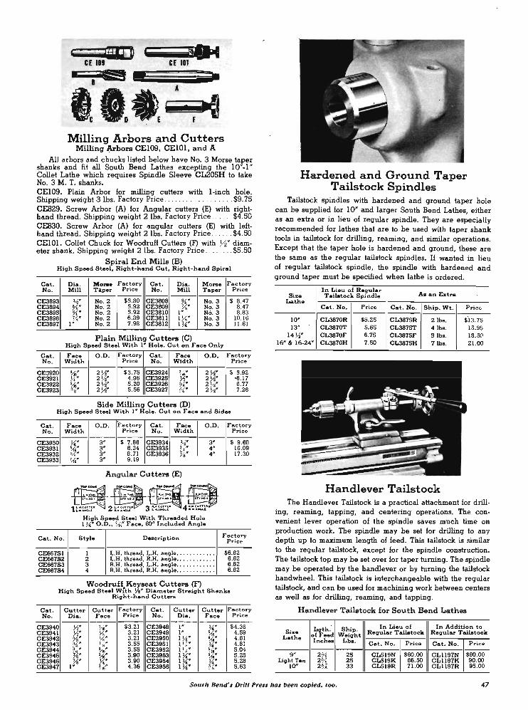
':aD CE III
• g • • I
'I,f), A
7 at Milling Arbors and Cutters
Milling J;'.rhors CEI09, CEIOl, and A
All arbors and chucks listed below have No. 3 Morse taper shanks and fit all South Bend Lathes excepting the 10"-1 ' Collet Lathe which requires Spindle Sleeve CL205H to take No. 3 M. T. shanks. CEI09. Plain Arbor for milling cutters with I-inch hole. Shipping weight 3 Ibs. Factory Price . . . . . . . . $9.75 CE829. Screw Arbor (A) for Angular cutters (E) with right-hand thread. Shipping weight 2 Ibs. Factory Price . . .... $4.50 CE830. Screw Arbor (A) for angular cutters (E) with left-hand thread. Shipping weight 2 Ibs. Factory Price ... . . . $4.50 CEIOl. Collet Chuck for Woodruff Cutters (F) with 72" diam-eter shank. Shipping weight 21bs. Factory Price . . ...... $5.50
Spiral End Mills (B) High Speed Steel, Right-hand Cut, R ight-hand Spiral
Cat. Dia . Mo ... Factory Cat. Die . Morse Factory No . Mill Taper Pri.ce No. Mill Taper Price
------------------------CE3893 Y." No. 2 $5.BO CE380B %'", No. 3 $ B.47 CE3B94 % " No. 2 5.92 CE3809 ~" No. 3 B.47 CE3895 :!1'" No. 2 5.92 CE3BI0 I " No. 3 B.B3 CE3B96 W No. 2 6 .B9 CE3Bll l Yo" No. 3 10.16 CE3B97 1 No. 2 7 .9B CE3812 I ~" No.3 11.61
Plain Milling Cutters (C) High Speed Steel With I " Hole. Cut on Face Only
Cat. Face 0 .0 . Factory Cat. Face 0 .0. Factory No. Width Price No. Width Price
------ ------CE3920 ~" 2 Y." $3.75 CE3924 J.16" 2 Y." $ 5 .92 CE3921 U" 2 Y." 4.96 CE3925 Y." 2 Y." -6.17 CE3922 ~'" 2 Y." 5 .20 CE3926 % " 2 Y." 6.77 CE3923 %* 2 Y." 5.56 CE3927 %" 2 Y." 7.26
Side Milling Cutters (D) High Speed Steel With I" Hole. Cut on Face and Sides
Cat. Face 0.0. Factory Cat. Face 0 .0. F actory No. Width Price No. Width Price
------------ CE3934 ---------CE3930 CE3931 CE3932 CE3933
Cat. No.
CE667S1 CE667S2 CE667S3 CE667S4
~" ~61J' %" U6'"
3" $ 7.B6 Y.-3 " B.34 CE3935 %'" 3" B.71 CE3936 ~" 3" 9 .19
Angular Cutters (E)
High Speed Steel With Threaded Hole 1 ~" 0.0., if .. Face, 60° Included Angle
3 -4" 4-
Style Description
1 2 3 4
L.H. thread, L.H. angle . .... ...... . L.H. thread, II .H. angle .. ... • .. .... R.H. thread, L.H. angle ........... . R.H. thread, II .H. angle ... . . ... . .. .
$ 9.6B 16.09 17.30
Factory Pric e
$6.B2 6.B2 6.B2 6.B2
Woodruff Keyseat Cutters (F) High Speed Steel W:th y." Dia=eter Straight Shanks
Right-hand Cutters
Cat. Cutter Cutter Factory Cat. Cutter Cutter Factory No . Dia. Face Price No. Dia. Face Price
------------ ------- ---CE3940 Y." !16* $3.21 CE394B I" ~" $4.36 CE3941 Y." Yo" 3.21 CE3949 1- ~6" 4.59 CE3942 %" yg" 3.21 CE3950 1 ).1;- ~" 4.BI CE3943 ~ .. 7f' 3 .55 CE3951 l Yo" ~" 4.BI CE3944 3 " ~t 3.55 CE3952 I H " '-1," 5 .04 /. CE3945 ~" 1M'" 3 .90 CE3953 1 ~" ';iG: 5.2B CE3946
l W ~" 3.90 CE3954 1 ~" ~" 5.2B
CE3947 J.,{611' 4.36 CE3955 1 ~" 5.63
Hardened and Ground Taper Tailstock Spindles
Tailstock spindles with hardened and ground taper hole can be supplied for 10' and larger South Bend Lathes, either as an extra or in lieu of regular spindle. They are especially recommended for lathes that are to be used with taper shank tools in tailstock for drilling, reaming, and similar operations. Except that the taper hole is hardened and ground, these are the same as the regular tailstock spindles. U wanted in lieu of regular tailstock spindle, the spindle with hardened and ground taper must be specified when lathe is ordered.
In Lieu of Regular A. an Extra Size Tailatock Spindle
Lathe Cat. No. Price Cat. No. Ship. Wt. Price
10" CL3B70R $5.25 CL3B75R 21bs. $'13.75 13" CL3B7OT 5.65 CL387ST 4 lb •. 15.95
14 ~" CL3B70F 6.75 CL3B75F Sib •. 18 .SO 16- « 16-24- CL3B70H 7.SO CL3B7SH 7 lb •. 21.00
Handlever Tailstock The Handlever Tailstock is a practical attachment for drill
ing, reaming, tapping, and centering operations. The convenient lever operation of the spindle saves much time on production work. The spindle may be set for drilling to any depth up to maximum length of feed. This tailstock is similar to the regular tailstock, except for the spindle construction. The tailstock top may be set over for taper turning. The spindle may be operated by the handlever or by turning the tailstock handwheel. This tailstock is interchangeable with the regular tailstock, and can be used for machining work between centers as well as for drilling, reaming, and tapping.
Handlever Tailstock for South Bend Lathes
Lgth. Ship. In Lieu of In Addition to Size Regular Tailatock Regular Tailatock
Lathe of Feed Weight Inch .. Lb • . Cat. No. Price Cat . No. P rice
9- 2 % 25 CL519N $60 .00 CL1l97N $BO. OO Light ren 2 % 25 CLSI9K 66.SO CL1l97K 90.00
10- 2 % 33 CLS19R 71.00 CL1l97R 95.00
South Bend's Drill Press has been copied, too. 47

External Grinding Attachments for South Bend Lathes
1-....1 GrIndln, AIIoch_t Moun"" on 16-1nch South ...... L .....
This powerful and efficient grinding attachment is recom· mended for grinding bushings, sharpening reamers and cutters, and other external grinding. Designed especially for South Bend Lathes, it is easily adaptable for use on other makes of lathes. The spindle revolves in prelubricated, precision ball bearings which are sealed to protect them from damage by dust, grit, and metal particles produced when grinding. Supplied with 7;1_1!.P., constant speed continuous duty motor, and 4 ' x 31' No. CE2759 general purpose grinding wheel. Spindle speed is approximately 5275 ·r.p.m.
Clamp bolt equipment is not included as it varies in design to conform with the various sizes of South Bend Lathes. When ordering the grinding attachment, be sure to include the clamp bolt equipment needed to mount the grinding attach· ment on the compound rest top of your lathe. See description and tabulation of clamp bolt equipment below.
Catalog Motor SpecificatioNi S~ping . Factory Number
Ph ... Cycle Volta eight Price
--'--
CE30IB I 60 115 43 lb •. $64.SO
CE30IBA 1 60 150 43 ib.. 68.SO
CE30ID . 1 60 230 43 lb •. 68. SO
CE30IA I 50 115 43 lbo. 66 .00
CE30IC 1 50 230 43 lb •. 70 .00
CE30IY 1 40 115 43 lb •. 68.SO
CE30IZ 1 40 230 431bo. 71.00 , CE30IK 1 25 230 43lbo. 71.00
CE303D 3 60 220 43lbo. 75.00
CE303F 3 60 440 43 lb •. 75.00
CE303C 3 50 220 43 lbo. 75.00
CE303E 3 50 440 43 lb •. 75.00
CE300K D.C. .. 115 43lbo. 92.00
. CE300L D.C . .. 230 43 lbo. 92.00
Clamp Bolt Equipment Required for Mounting Grinding Attachment on Lathe
The equipment supplied with each External Grinding Attachment does not include the clamp bolt and other fittings neceBBary for mounting the grinding attachment on the lathe. The Clamp Bolt Equipment required for various sizes of South Bend Lathes is listed in the table. Be sure to include the reo quired Clamp Bolt Equipment when ordering an External Grinding Attachment.
Tailstock Diamond Holding Fixture
Clamps to tailstock spindle of lathe for holding the No. CE406 diamond dresser (shown in inset) for truing grind· ing wheel. Cannot be used while work is mounted between the lathe centers. Prices shown in table do not include diamond dresser which is listed below.
No. CE406. Diamond Dresser. Ship wt. 31 lb. Price ... . ......... . $7.85
Cat. No.
CESINK
gg~~ CESIF CESIH
Sia. Lathe
9" ciLt. Ten 10* 13" 14 ~"
IS" ci 16-24"
Ship. Fac· tory
Wt. Price --
3 lb •. $9.50 31b • . B.SO 4 lb •. 9 .75 4lbo. 9 .75 5lbo. 11.00
Catalog Lathe Shipping Factory Price NUn\b.r Size Weight
CE307NK 9" & Lt. Ten 1 lb. $2.00 CE307R 10* lib. 2.SO CE307T 13" 3lbo. 3.00 CE307F 14~" 3lbo. 3.SO CE307H IS' & 16-24" 4 !ba. 3.SO
Extra Grinding Wheels For External Grinding Attachment
",~., , .. ~:,!: '
~.'"
For rapid grinding and smooth finish, the correct grade of grinding wheel should be selected. The grinding wheels listed cover the more important classes of work. Wheels listed in table are 4' in diameter with 31' face and 31' hole, to fit external grinding attachment. Shipping 'weight 2 lbs.
Cat. No. Typa of Work CI_ofWork Price
CE2759 General Work . •.••..... . Rou'lh or Finiah $2.35 CE2759 Cultin'l Toolo ..... . .. ... . Rou'lh or Finiah 2 .35 CE2774 Aulomobile Val" ..... .... Rou'lh or Finiah 2.35 CE2757 Coal Iron ... .. .. . ....... Finiah Grlndin'l 2 .80 CE2769 SOIlSI .. I. ...... .. ...... Finiah Grlndin'l 2.35
No. CE3236. Cup Grinding Wheel, 3 7;1' 0.0., 17;1' face, 31' hole for sharpening reamers and cutters. Price ... . $3.60
4. You get more for your money when you buy South Bend.

Reamer Grinding . Stops
For sharpeninq reamers, millinq cutters, etc., havinq either straiqht or spiral flutes. Also used for holdinq the No. CE 18 Diamond Dresser listed below.
Cat. Size Ship. Fac -No. Lathe Wt. tor y
Price ---CEISIZH 9" 7 lb • . $20 .7S CEISI2K Lt. Ten Sib •. 21.2S CEISI2R 10" 9 lb • . 22.00 CEISI2T 13" 14 lb •. 24.7S CEISI2F 14 )1" 20 lb •. 27.25 CEISI2H 16" 24 lb •. 27.25 CEISI2V 16-24" 30 lb •. 40.00
Diamond Dresser
For satisfactory operatiQn, the qrindinq wheel should be trued frequently with a diamond dresser. This dresser must be mounted in the Reamer Grindinq Stop fixture, listed above. Price does not include the fixture.
No. CE18. Diamond Dresser only. Shippinq weiqht 1 lb. Price .. . .. $9.25
-If'1--
~;'?~
r-1r--1 .....
:~.}'~ -~ I.j d - "8
STYLE A STYLE B sfraight wheel mounted wheel
Grinding Wheels for Internal Grinding Attachment
Grindinq wheels listed below are for use with the South Bend Internal Grindinq Attachment or other qrinder of similiar size and speed. Grit and grain are suitable for qeneral purpose qrindinq on bushinqs, tools, etc. Shippinq weiqht approximately 4 oz. each wheel.
Catalog Factory Number Style Diameter Face Price
CE2925 A W ~' $ .50 CE2926 A ~' ~' .50
CE2927 A Ys' U· .50 CE2928 A I' ~' .50
CE3035 B W ~8· .55
CE3036 B I " / 2 W .55 CE3037 B ~' 711' .60 CE3038 B I' W .65 CE3039 B
,,. ," W .55 CE3040 B W W .55 CE3041 B ~ .. ~' .55
CE3042 B W U· .55 CE3043 B ~ .. W .55 CE3044 B W .,,' .. .55 CE3045 B ,1'2· W .55 CE3046 B Ys. ~' .60 CE3047 B ~' W .60 CE3048 B Ys' 7{. .65 CE3049 B I' ~' .65
Righ t - Compour:d Belting Drives Grinding Wheel at 30,000 r.p.m.
Below- Internal Grinding Attachment on 10" Lathe.
Internal Grinding Attachment This new South Bend Constant Speed Precision Grinder
has been developed to meet the lonq felt need for an intemal qrindinq attachment havinq sufficient power to maintain a more constant wheel speed under varyinq loads and to prevent stallinq under comparatively heavy cuts.
The qrinder is powered by a standard 'type, constant speed, continuous duty 1/ 6 h.p., 3450 r .p.m., A.C. motor which has proved to be far superior to ,the universal type A.C.-D.C. motors ordinarily used. The motor is compound belted, throuqh an intermediate shaft to obtain a quill spindle speed of 30,000 r.p.m. Tests have shown that less than 1000 r.p.m: drop in spindle speed occurs when takinq cuts as heavy as .003" on a side in hardened steel. Power loss is negligible.
The grindinq wheel and intermediate shaft spindle run on high precision, hiqh speed ball bearinqs which require no adjustment. Lubricant is supplied from built-in oil wells. Oil is effectively sealed in the spindle units, and dust sealed out in such a way that the bearinqs will retain their precision indefinitely. The compound beltinq and the three pulleys are enclosed by a one-piece quard. .
This qrinder can be easily adapted for use on othennalces of lathes or on other machine tools. Grinders have 1 ph., 60 cy., 115 v., A.C. motor, and accessories as listed below under specifications. Shippinq weiqht 51 Ibs.
Specifications Grinding wheel speed . . . .. . . .. . . . . .... . .. . . . . . . . .. .. . . . . 30.000 r .p.m. Maximum depth 01 ground hole with I·inch wheeL .. . . .. . . .. . 3Ys inches Maximum wheel diameter recommended ... . . . . .. . . ... . . .. . . . . . .. 1 inch Accessories supplied:
Four J4~ wheel arbors; lengths 2~"' .. 2 1~K"'. 3~"', and 41M~ . Four qrlndinq wheels: }i'" bore; )4 '" face; %", ~"', Ya", "and 1" diameters. One chuck lor mounted wheels . .. ... . ... . . ....... . ... . 711" capacity Eiqht-foot e:denaion cord, pluq, and switch.
No. CE601B. Intemal Grindinq Attachment with 1 ph., 60 cy., 115 v., A.C. motor and accessories listed above, but without clamp bolt equipment. Price £.o.h. factory .. . . $167.50 Write for information and prices of qrinders equipped with motors for other current characteristics.
Clamp Bolt Equipment Required lor mounting Internal Grinding Attachment on Lathe.
Catalog Lathe Shipping Factory NUn\ber Size VII eight Price
CE307NK 9 " & Lt. Ten lib. $2.00 CE307R 10" lib. 2 .50 CE307T 13" 3 lb •. 3.00 CE307F 14~" 31bs. 3.50 CE307H 16" & 16-24" 4lbs. 3.50
South Bend Drill Presses are deligned and buUt in the same shops and to the same .tandords as South Bend Lothes. 49

Thread Indicator ~liminatell revening of
lathe spindle when cutting threads. Dial is numbered and qraduated to show when to close half-nuts on lead screw to catch the thread on each successive cut, after returning carriage . to the starting point. For English pitches only. See page 61 for metric thread indicator dial. -
Catalog Si •• Number Lathe
CL810NK 9" & Light Ten CLBIOR 10" CL810TH 13", 14 W , 16", 16-24", 2-H
Shipping Factory Weight Price
2lba. $11.75 3lba. 18.00 5lba. 20.75
Four Position Carriage Stop Much time can be
saved in positioning the cutting tool for repetitive operations by using this four position carriage stop. Each of the four adjustable stops may be set for a different tool position and may be revolved into pbsition to locate the carriage for each of four successive cuts. This attachment is especially
desirable for spacing shoulders in shafts and similar operations.
Catalog Sis. Shipping Factory Nuznber Lathe Weight Price
CL2185NK 9".& Light Ten 6lba. $23.75 CL2185RT 10" & 13" 6lba. 25. 75 CL2185FH 14 ~', 16', 16-24', & 2-H 10 lba. 28 .50
Dial Indica~or Carriage Stop Repetitive facing, shoul
dering or grooving operations can be performed with speed and precision on lathes equipped with a dial indicator type carriage stop. Position of carriage is clearly shown on face of dial which has 100 graduations reading in thousandths of an inch. Dial indicator hand will make 2 7':; rev
'olutions indicating a total movement of .250' .
Enclosed in heavy metal case with hinged lid, the indicator is well protected at all times. Case is so constructed that indicator is protected from accidental damage by excessive pressure of carriage against indicator.
Two mounting brackets are supplied, one for work close to headstock as shown in upper illustration and the other for any position along length of bed. Indicator support bar has 5 7':;' adjustment in bracket. Price includes one dial indicator, indicator case with hinged lid, and two mounting brackets.
CL2795RT. Dial Indicator Carriage Stop for 10' or 13' Lathe. Shipping wt. 10 lbs. Price .. . . . . . . . . c$-37.50
CL2795FH. Dial Indicator Carriage Stop for 147':;', 16', 16-24' or 2-H Lathe. Ship. wt. 12lbs. Price . . ... . .. . . . $41.00
Micrometer Carriage Stop This attachment is useful for
accurate facing, turning, boiing, etc. It is used for locating the carriage at any point along lathe bed. Can be used on either side of carriage. Has 'ac,curately qraduated micrometer collar. Either English or metric qradua~ons can be supplied.
The stop is hardened on both ends and may be locked . for repetitive operations on duplicate work.
EnglUh Metric
SlseLathe Ship Oraduationa Graduationa Wt. Cat. No. Price . Cat. No. Price
9" & 'tg!'t Ten 2lba. CL968NK $20.95 CL968NKME $20.95 4lba. CL968R 22.00 CL968RME 22.00
13' 4 lb •. CL968T 24 . 75 CL968TME 24.75 14 ~', 16', 16-24', & 2-H 7 lb •. CL968FH 25.75 CL868FHME 25.75
Catal09 Numb_
CL758NK CL758R CL758T CL758FH
Catal09 Nuznber
CL22SONK CL2250R CL2290T CL2250F CL2250H
Plain Carriage Stop
Si ..
'fhia 1Il0p -may- be ~clamped onto the front V-way of the lathe bed, on either side of the saddle, to locate the position of the cutting tool for facing, necking, cutting shoulders, machining qroovea, and similar operations_
Shipping Factory Lathe Weight Price
9" & 'tg!'t Ten 2 lb •. $4 .75 4lba. 5.00
13' 41be. S.OO 14 ~', 16', 16-24', & 2-H 7lba. 7.50
Thread Cutting Stop
Si .. Lathe
The Thread Cutting Stop is clamped onto the saddle crossslide dovetail and is used for regulating the depth of cut for each succeaaive chip when cutting screw threads. Price includes stop complete with clamp and knurled thumb screw.
Shipping Factory Weight Price
9" & X:g!'t Ten ~ Ib. $5.25 ~ Ib. 5.50
13' 1 14 ~' 1
16' & 16-24' 2
lb. lb. lba.
6 .25 7.00 7.75
Four Position
Cross Slide Stop
This stop fits onto the saddle and is used with the double tool cr088 slide in place of the regular cr088 slide stop. See paqe 41. It has four adjustable stopa for locatinq the positiQn of the C\lt. ting tools for each of four successive operations.
Cat. No. Slaa Lathe Ship. Wt. Price
CL2154NR 9" and 10" 2lba. $15.50 CL2154T 13' 3lba. · IS.00 CL2154H 16' and No. 2-H 3lba. 19.25
50 AI tM proof of the puddin, u in the _ting-so the tut of G tool u in it. performanu.
'I'
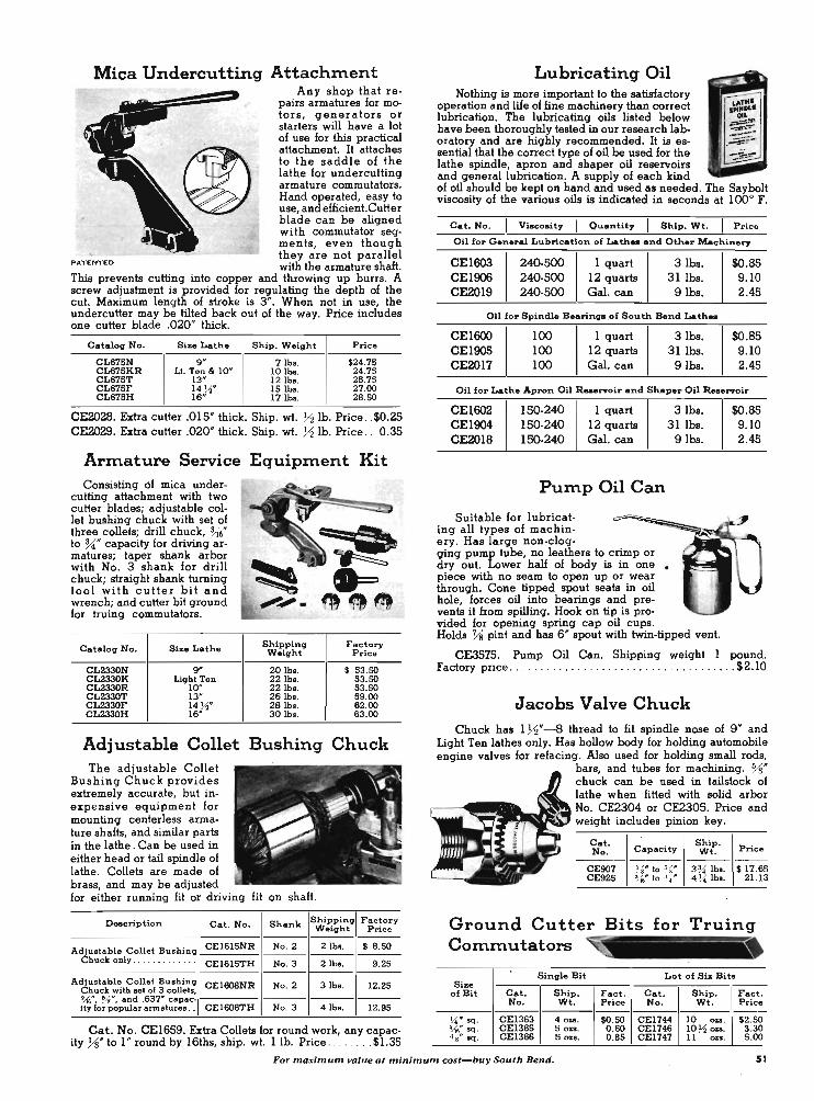
Mica Undercutting Attachment Any shop that re
pairs armatures for motors , generators or starters will have a lot of use for this practical attachment. It attaches to the saddle of the lathe for undercutting armature commutators. Hand operated, easy to use, and efficient. Cutter blade can be aligned with commutator segments, even though
~ they are not parallel PATENTED with the armature shaft. This prevents cutting into copper and throwing up burrs. A screw adjustment is provided for regulating the depth of the cut. Maximum length of stroke is 3". When not in use, the undercutter may be tilted back out of the way. Price includes one cutter blade .020" thick.
Catalog No . Size Lathe Ship. Weight Price
CL675N 9 " 7 lb •. $24.75 CL675KR Lt. Ten &< 10" 10 lb •. 24 .75 CL675T 13" 12lbs. 25 .75 CL675F 14 ~' Is·lb •. 27 .00 CL675H 16" 171bs. 28. SO
CE2028. Extra cutter .015" thick. Ship. wt. % lb. Price . . $0.25 CE2029. Extra cutter .020" thick. Ship. wt. % lb. Price .. 0.35
Armature Service Equipment Kit Consisting 6f mica under
cutting attachment with two cutter blades; adjustable col· let bushing chuck with set of three collets; drill chuck, ~6" to %;" capacity for driving ar· matures; taper shank arbor with No. 3 shank for drill chuck; straight shank turning tool with cutter bit and wrench; and cutter bit ground for truing commutators.
Catalog No. Size Lathe
CL2330N go CL2330K Liqht Ten CL2330R 10" CL2330T 13" CL2330F 14 ~" CL2330H 16h
Shipping Factory Weight Price
20 lbs. $ 53.SO 22lbs. S3.SO 22lbs. 53.SO 26lbs. 59.00 28 lb • . 62.00 30 lbs. 63.00
Adjustable Collet Bushing Chuck The adjustable Collet
Bushing Chuck provides extremely accurate, but inexpensive equipment for mounting centerless armature shafts, and similar parts in the lathe . Can be used in either head or tail spindle of lathe. Collets are made of brass, and may be adjusted for either running fit or driving fit on shaft.
Description Cat. No . Shank Shippinq Weight ---
Adjustable Collet Bushinq CEI61sNR No. 2 2 lb • . ---Chuck only . .... .. ... .. . CEI61sTH No. 3 2 lbs. ---
Adjustable Collet Bushinq CEI608NR No. 2 3 lbs. Chuck with aet 01 3 collet •• '.-16"', %11', and .637# capac- ------ity for popular armatures . . CEI608TH No. 3 4 lb •.
Factory Price ---
$ 8.SO ---9.25
---12.25
---12.95
Cat. No. CE16S9. Extra Collets for round work, any capac-ity ~. to I " round by 16ths, ship. wt. lIb. Price .... . . .. $1.35
Lubricating Oil Nothing is more important to the satisfactory
operation and We of fine machinery than correct lubrication. The lubricating oils listed below have been thoroughly tested in our research laboratory and are highly recommended. It is essential that the correct type of oil be used for the lathe spindle, apron and shaper oil reservoirs and general lubrication. A supply of each kind of oil should be kept on hand and used as needed. The Saybolt viscosity of the various oils is indicated in seconds at 100° F.
Cat. No . I Visco.ity I Quantity I Ship. Wt. I Price
Oil for General Lubrication of Lathe. and Other Machinery
CEl603 240-500 1 quart 31bs. $O.B5 CEl906 240-500 12 quarts 31 Ibs. 9.10 CE2019 240-500 Gal. can 9Ibs. 2.45
Oil for Spindle Be.rinqa of South Bend Lathe.
CEl600 100 1 quart 31bs. $O.B5 CEl905 100 12 quarts 311bs. 9.10 CE2017 100 Gal. can 91bs. 2.45
Oil for Lathe Apron Oil R ........ oir and Shaper Oil Re_rvoir
CEl602 150-240 1 quart CEl904 150-240 12 quarts CE201B 150-240 Gal. can
Pump Oil Can
Suitable for lubricating all types of machinery. Has large non-clog-ging pump tube, no leathers to crimp or dry out. Lower half of body is in one piece with no seam to open up or wear through. Cone tipped spout seats in oil hole, forces oil into bearings and prevents it from spilling. Hook on tip is provided for opening spring cap oil cups.
31bs. 311bs.
91bs.
Holds Ys pint and has 6" spout with twin-tipped vent.
$O.B5 9.10 2.45
CE3S75. Pump Oil Can. Shipping weight 1 pound. Factory price . .. . . .. ..... .. ...... . . . . . ... . . ....... $2.10
Jacobs Valve Chuck Chuck has 1 %"--8 thread to fit spindle nose of 9" and
Light Ten lathes only. Has hollow body for holding automobile engine valves for refacing. Also used for holding small rods,
bars, and tubes for machining. Ys" chuck can be used in taUstock of lathe when fitted with solid arbor No. CE2304 or CE230S. Price and
~_.l'ii.~ weight includes pinion key.
Cat. Capacity
Ship. Price No. Wt.
-----CE907 ~ 8* to %" . 3 r.l lbs. $ 17.65 CE925 ~" to ~:t " 4 Ji lbs. 2J.J3
Ground Cutter Bits for Truing Commutators
Sinqle Bit Lot of Six Bits Size
of Bit Cat. Ship . Fact . Cat. Ship. I Fact . No. Wt. Price No. Wt. Price
Ji" sq. CEI363 4 0u. $O.SO CEI744 10 0 ... \ $2.SO 'M" sq. CEI365 5018. 0.60 CE1746 10 Yo 0... 3.30 ~~" sq. CEI366 50zs. 0 .85 CEl747 II 00. 5 .00
For maxim/Jm value at minimum cost-buy South Bend. 51

Lathe Centers and Drill Pads G-Drill Pad, uaed in lailslock 10 .upport fial work lor drilling . H -Crotch Center, used in tailstock for drilling round work. 1·-60" Center made of tool .teel, heat.treated, hardened, and ground
all over. For use in headstock or tailstock. J-60° Hollow Center for .upporting centerl ... armature shalto, etc. L-Screw Center lor wood turning.
M-Spur Center lor wood turning. N- Cup Cenler for wood turning. P-Carbide Tipped Center for heavy duty 11M in tailstock. Q-Hall Center, u.ed in tailotock for lacing ends 01 .hafts.
Catalog O_cription
Morse Ship. Number Taper Wt.
Factory Price ------
CE2396 G-Drill Pad ...... . ... . .. . No. 2 3 lb • . $ 3.20 CE2397 G - Drill Pad .. ...... .. . . . . No. 3 4lba. 3.50 CE2398 H-Crotch Center ... . . .. . . No. 2 2 lb •. 3.20 CE2399 H-Crotch Center ......... No.3 3 lb • . 4.20 CE2401 1-60" Center ...... ...... No.2 lib. 2 .90 CE2402 1-60" Center .. .... . ... . . No. 3 2 lb • . 3.80 CEI896 J- Hollow Center ...... .. . No. 2 2 lb • . 3.20 CEI897 J~Hollow Center ....... . . No.3 2lba. 4.10 CE2413 L- Screw Center . . . . . .... No.2 31be. 3.80 CE2414 L- Screw Cenler .... ..... No. 3 4lba. 4.20 CE2416 M- Spur Cenler . .. . . . .. ... No. 2 2 lb •. 3.80 CE2417 M-~ur Cenler .... ....... No. 3 5 lb • . 4.20 CE2422 N- up Cenler .. ...... .. . No. 2 lib. 2.60 CE2423 N- Cup Cenler . .. . .... ... No. 3 2 lb •. 3 .50 CEI689 P- Carbide Center ..•.... . No. 2 I lb. 5 .75 CEI890 P-Carbide Center . . ...... No. 3 2 lb • . 10.25 CE2424 Q-Hall Center .. . ........ No. 2 I lb. 2.90 CE2425 Q-Half Cenler ... . . .. ... . No. 3 2lba. I 3.80
Ball Bearing Live Centers Designed for maximum
precision, strength and rigidity, the Ball Beaiing Live Centers are recommended for high speeds and heavy roughing cuts. Concentricity of center point is guaranteed within ± .0000IS*. Two styles are available, one having a 60° external point as shown above at right, and one having a 60° hollow as shown in the lower illustration. Both styles are made with No. 2 and No.3 Morse standard tapers. Ball bearing is easily replaceable.
Catalog Styla of Nuznber Center
CE3900 60° Poinl CE3901 60° Point CE3903 50° Hollow CE3904 60° Hollow '
Mo1'8e Taper
No. 2 No.3 No. 2 No. 3
Combination Center Drill and Countersink
Shipping Weiqht
Factory Price
3 lb • . . $ 16.65 5 lb • . 19.65 3 lb •. 16.65 5 lb •. 19.65
For drilling center hole and countersinking 60° angle for lathe center. Made of high speed tool steel.
Sinqle Drill Lot of Twal .. Di •. of Dia. of
Cat. Ship. Drill Body Factory Cat. Ship. Factory No. Wt. Price No. Wt. Price ------------------ - ---
J..{t ~ .. CE2087 4ou. $ .98 CE2555 Bou. $11.75 • ~* ' 0* CE3021 4ou. .98 CE302S B ou. 11.75 .. ~" ~* CE3022 4ou. .98 CE3026 8 au. 11.75 ~i" ~ f6'" CE3023 4 OZI. . 98 CE3027 I lb. 11.75 ~" 7.1,'" CE3024 6ou. 1.48 CE3028 2lba. 17.75
Cat. No. CE3020. Set of S Combination Center Drills and Countersinks, one each of above. Factory Price .. ... ... $5.40
Pipe Centers
For mounting tubing, pipe, etc" between the lathe centers for machining. Centers have accurately ground 90° cone, and revolve on steel shanks with plain bearings.
Pipe Centers
Cat. Tak .. Requiraa Shipping No. Pipe Shank Weight
CE2160 Yo" 10 3 " CE2172 4 lb • . or
CE2161 . 3" to 511' CE2174 6 lb •.
CE2162 5 " to 8 '" CE2173 17 lba.
Pipe Center Shanks
Cat. Shank Tak. Shipping No. Taper Centers Weight
CEZI72 No. 2 CE2160 & CE2161 2 lb • . CE2174 No. 3 CE2160 & CE2161 3 lb •. CE2173 No. 3 CE2162 4 lb •.
Hardened Pipe Center CE2163, Takes pipe Y2* to 3 ". Same as CE2 I 50,
but made of heat-treated and hardened steel. $6.70
Ball Bearing Pipe Centers Fitted with large, double
row ball bearings, these extra large precision centers provide rigid support for pipe and other large diameter work. Tight fitting seal protects bearings from dust.
Cataloq Style of Nuznber Center Capacity
CE2445 90° Point ~" to3 1/sA' CE2446 90° Point ~" to 3 Ji" CE2449 90° Point 3 ; 8" to 8%" CE2447 90° Hollow ~., to 3~"" CE2448 90° Hollow ~ t6" to 3~16"
Morae Shippinq Taper Weiqht
No. 2 '9 lb •. No. 3 9lba. No.3 20 lbo. No. 2 Blba. No. 3 Bib • .
Factory Price
S 5.75
7.85
1l.sO
Factory Price
S 4.95 5.70 9 .65
Factory Price
$37.50 39.50 54.50 37.50 39.50
Center Drill Holder The Center Drill Holder
is designed for greater accuracy in center drilling, Holds drill rigidly.
Catalog Taper Diameter Shipping Factory Nuznber Shank Will Hold Weiqht Price
CE2338 No. 2 Yo" I lb. $3.20 CE30Z9 No. 2 Ho" lib. 3.20 CE2340 No. 2 u"' .... I lb. 3 .20 CE2339 No. 2 I~" I lb. 3 .20 CE3030 No. 2 ~* I lb. 3.20 CE2341 No. 2 .302" lib. 3.20 CE3031 No. 2 s~.., I lb. 3.20 CE2342 No. 2 " " II I lb. 3.20 CE2346 No. 3 Yo" 2lba. 4.10 CE3032 No. 3 . ''''' .. 2lba. 4.10 CE2343 No. 3 IJ~' 2lba . 4.10 CE2347 No.3 15",111 2lba. 4.10 CE3033 No. 3 ~" 2 lb •. 4. 10 CE2344 No. 3 .302" 2lba. 4.10 CE3034 No. 3 Uo* 2lba. 4.10 CE2345 No. 3 ' .. " 2 lb • . 4.10
52 South Bend', ShDper will"., copied we truly e"pe<;t.
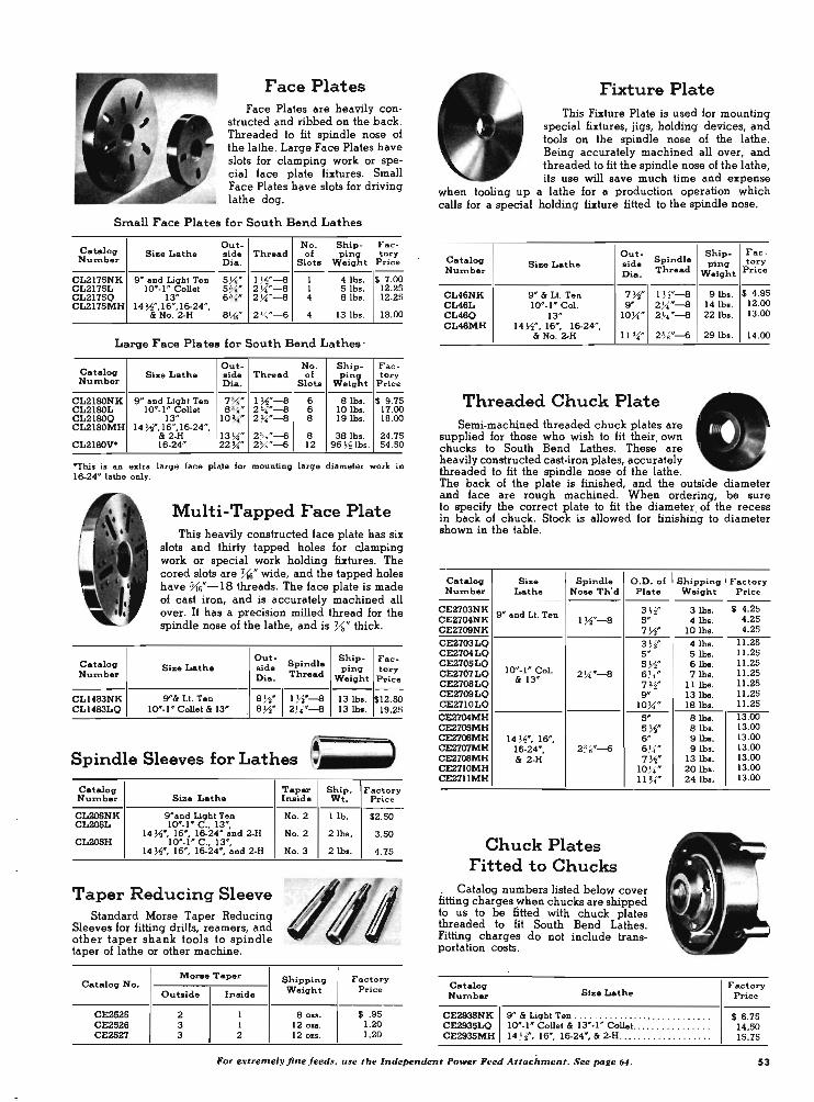
Face Plates Face Plates are heavily con
structed and ribbed on the back. Threaded to fit spindle nose of the lathe. Large Face Plates have slols for clamping work or special face plate fixtures. Small Face Plates have slots for driving lathe dog.
Small Face Plates for South Bend Lathes
Catalog Out- No. Ship- Fac-
Size Lathe aide Thread of pinq tory Number Dia . Siou Weight Price
-----------CL2175NK 9" and Light Ten 5 J.i" I ~"-a I 4 lhs. $ 7.00 CL2175L 10"·1 " Collet 5 %" 2 ~'-a I 5lbs. 12.25 CL2175Q 13" 6 l'1~H 2 ~'-a 4 8lhs. 12.25 CL2175MH 14 ~", 16",16·24",
& No. 2·H 8~" 2 %"-6 4 13lhs. 18.00
Large Face Plates for South Bend Lathes '
Catalog Out- No. Ship- F ae-
Size Lathe aide Thread of ping tory Number Dia. Siou Weight Price
-----------CL2180NK 9" and Light Ten 7 % " 1 ~"-8 6 8lbs. $ 9.75 CL2180L 10"·1" Collet 83~" 2 ~"-8 6 10 lb •. 17.00 CL21BOQ 13" 10 ~" 2 ~'-8 8 19 lhs. 18.00 CL2180MH 14 ~", 16", 16-24",
& 2·H 13 ~" 2 '7."-6 8 38 lh •. 24.75 CL2180V* 16·24" 22 ~" 2 %"-6 12 96 ~ lbs . 54.50
--rhis is an extra large face plale for mounting large diameter worle in 16-24" lathe only.
Catalog Number
CLI483NK CLI483LQ
Multi-Tapped Face Plate This heavily constructed face plate has six
slots and thirty tapped holes for cjamping work or special work holding fixtures. The cored slots are 'Us" wide, and the tapped holes have Vt6"- 18 threads. The face plate is made of cast iron, and is accurately machined all over. It has a precision milled thread for the spindle nose of the lathe, and is %" thick.
Out-Spindle
Ship- Fac -Size Lathe aide ping tory
Dia. Thread Weight Price --
9"& Lt. Ten 8 ~" l W -a 13 lh •. $12.SO 10"·1" Collet & 13" 8 ~" 2~~"-8 13 lhl. 19.25
Spindle Sleeves for Lathes ~~ ••••
Catalog Nurnber Size Lathe
CL20SNK g"ond Light Ten CL20SL 10"·1" C ., 13",
14 ~", 16", 16-24" and 2·H CL205H 10"·1" C., 13",
14 ~", 16", 16-24", and 2·H
Taper Reducing Sleeve Standard Morse Taper Reducing
Sleeves fo~ fitting drills, reamers, and other taper shank tools to spindle taper of lathe or other machine.
Mon:. Taper Catalog No.
Ouuide Inside
CE2S25 2 I CE2526 3 I CE2S27 3 2
Taper Ship. Factory Inaide Wt. Price ------No. 2 I lb. $2.SO
No. 2 2 lhs . 3.SO
No. 3 2lbs. 4.75
/1/ Shipping Factory Weight Price
80u. $ .95 12ozs. 1.20 120&8. 1.20
Fixture Plate This Fixture Plate is used for mounting
special fixtures, jigs, holding devices, and tools on the spindle nose of the lathe. Being accurately machined all over, and threaded. to lit the spindle nose of the lathe, its use will save much time and expense
when tooling up a lathe for a production operation which calls for a special holding fixture litted to the spindle nose.
Out- Ship- Fac -Catalog Spindle Size Lathe aide ping tory Num.ber Thread Price Oia. Weight
--CL46NK g" & Lt. Ten 7 Yo" I J,f"-a 9lhs. $ 4.95 CL46L 10"·1" Col. g" 2 X"-a 14lhs. 12.00 CL46Q 13" 10~" 2 7.\' "-a 22lha. 13.00 CL46MH 14 ~" , 16", 16·24",
& No. 2·H 11 ~" 2 %"-6 29lhs. 14.00
Threaded Chuck Plate Semi·machined threaded chuck plates are
supplied for those who wish to fit their, own chucks to South Bend Lathes. These are heavily constructed cast· iron plates, accurately threaded to fit the spindle nose of the lathe. The back of the plate is finished, and the outside diameter and face are rough machined. When ordering, be sure to specify the correct plate to fit the diameter . of the recess in back of chuck. Stock is allowed for finishing to diameter shown in the table.
Catalog Size Spindle Number Lathe Nose Th'd
CE2703NK g" and LI. Ten CE2704NK l Yo"-a CE2709NK CE2703LQ CE2704LQ CE2705LQ CE2707LQ 10"·1" Col. 2~"-a CE2708LQ & 13"
CE2709LQ CE2710LQ
CE2704MH CE210SMH CE2706MH 14 ~", 16", CE2707MH 16-24", 2 % "-6 CE2708MH & 2·H CE2710MH CE2711MH
Chuck Plates Fitted to Chucks
0.0. of Plate ---3 ~" 5 " 7 Yo" 3 Yo" 5" 5 Yo" 6 . " 7 Yo" 9"
107.\'" 5" 5 Yo" 6" 6 1/, .11' A
7 W 107.\' " 11 ~f'
. Catalog numbers listed below cover fitting charges when chucks are shipped to us to be fitted with chuck plates threaded to fit South Bend Lathes. Fitting charges do not include trans· portation costs.
Catalog Number Size Lathe
Shipping Weight
3lhs. 4lhs.
10 lh •.
4lhs. 5lh • . 6lhs. 7lh • .
U lh • . 131bs. 18 lh • . 8lh •. 8lhs. 9lhs. 9 lh •.
13 lh • . 20 lhs. 241bs.
CE2935NK CE2935LQ CE2935MH
g" & Light Ten .. ...... .. .... . .. .. . .• ...... 10"·1" Collet & 13"·1" Collet ...... .. . . . .... . 14 H", 16", 16-24", .& 2·H .......... . . .. .. .. .
Factory Price ----
$ 4.25 4.25 4.25
11.25 11.25 11.25 11.25 11.25 11 .25 11.25
l3.OO 13.00 13.00 13.00 13.00 13.00 13.00
Factory Price
$ 6 .75 14. SO 15.75
For extremely jine feeds, use the Independent Power Feed Attachment. See page 64. 53
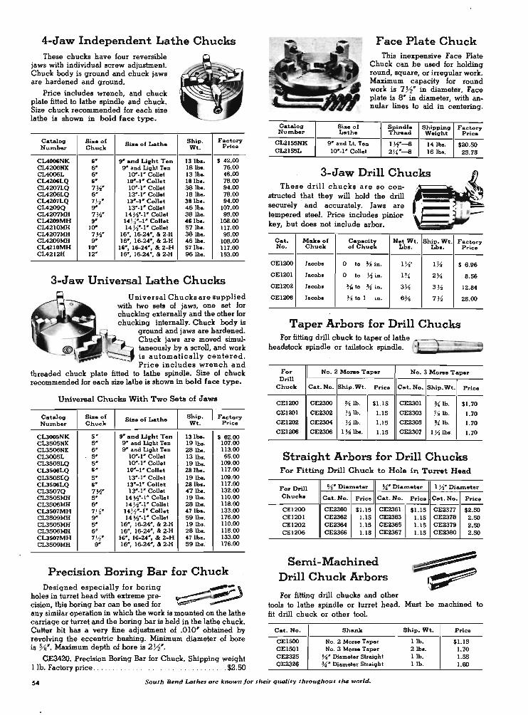
4-Jaw Independent Lathe Chucks These chucks have four reversible
jaws with individual screw adjustment. Chuck body is ground and chuck jaws are hardened and ground.
Price includes wrench, and chuck plate fitted to lathe spindle and chuck. Size chuck recommended for each size lathe is shown in bold face type.
Catalog Size of Size of Lath. NUlmber Chuck
CU006NK 6' 9" and Licht Ten CL4206NK 6' 9" and Light T.n CIAOO6L 6 ' 10"·1' Collel CL4206LQ 6' 10"-1' Collet CL4207LQ 7 ~' 10"·1' Collel CL4206LQ 6 ' 13' ·1' Coll.I CL4207LQ 7Yz' 13' -1' Collet CL4209Q 9" 13' ·1' Collel CL4207MH 7 ~' 14~'.1' Collet CL4209MH 9" 14Y,'-1" Collet CL4210MH 10" 14 ~'. 1' Collel CL4207MH 7 ~' 16' , 16-24', & 2·H CL4209MH 9" 16', 16-24', & 2·H CL4210MH 10" 16' , 16-24' , &: 2-H CL4212H 12' 16', 16-24' , & 2.H
Ship. Factory Wt. Price
13 lb •• $ 42.00 18 Jbe. 76.00 13 lba. 46.00 18 lb •• 78.00 38 Jbe. 94.00 18 lb •. 78.00 38 lb •• 94.00 46 Jbe. 107.00 38 Jbe. 95.00 46 lb •• 108.00 57 lba. 117.00 38 lb •. 95.00 46 Jbe. 108.00 57 lb •• 117.00 96 Jbe. 153.00
3-Jaw Universal Lathe Chucks Universal Chucks are supplied
with two sets of jaws, one set for chucking externally and the other for chucking internally. Chuck body is
ground and jaws are hardened. Chuck jaws are moved simul· taneously by a scroll, and work is automatically centered. Price includes wrench and
threaded chuck plate fitted to lathe spindle. Size of chuck recommended for each size lathe is shown in bold face type.
Universal Chucks With Two Sets of Jaws
Catalog Size of Size of Lathe Ship. Factory Num.ber Chuck Wt. Price
CLlOO5NK 5 ' 9' and Licht Ten 131ba. $ 82.00 CL3S05NK 5' 9" and Light Ten 19 lb •. 107.00 CL3506NK 6' 9" and Lighl Ten 28 lba. 113.00 CL3005L 5' 10"·1' Collel 13 lb •. 65.00 CL3S05LQ 5' 10"·1' Collel 19 lb •. 109.00 CLl506LQ 6 ' 10' -1 ' Collet 28lba. 117.00 CL350SLQ 5 ' 13'·1' Collel 19 Jbe. 109.00 CL3506LQ 6' 13' -1' Collet 28 lb •• 117.00 CL3507Q 7 ~' 13'·1' Collet 47 lb • . 132.00 CL3S0SMH 5' 14~'·1' Collet 19 lb •. 110.00 CL3506MH 6' 14 ~'.1' Collel 28 lb • . 118.00 CL3507MH 7Y,' 14Yz' -J' Collet 47 lb •• 133.00 CL3509MH 9" 14 MO.l' Collel 59 lb • . 176.00 CL3SOSMH 5 ' 16' , 16-24' , & 2·H 19 lbl. 110.00 CL3506MH 6' 16", 16-24', & 2·H 28 lb •. 118.00 CLl507MH 7Yz' 16', 16-24' , &: 2-H 47 lb •• 133.00 CL3S09MH 9" 16' , 16-24', & 2·H 59 lb.: 176.00
Precision Boring Bar for Chuck Designed especially for boring ~~
holes in turret head with extreme pre-cision, this boring bar can be used for any similar operation in which the work is mounted on the lathe carriage or turret and the boring bar is held in the lathe chuck. Cutter bit has a very fine adjustment of .010' obtained by revolving the eccentric bushing. Minimum diameter of bore is %'. Maximum depth of bore is 2Yz".
CE3420. Precision Boring Bar for Chuck. Shipping weight lib. Factory price . . . . . . . .. . $2.50
Catalog Size of Number Lathe
CL21SSNK 9" and Lt. Ten CL21SSL 10"-1' Collet
Face Plate Chuck This inexpensive Face Plate
Chuck can be used for holding round, square, or irregular work. Maximum capacity for round work is 7Yz' in diameter. Face plate is S" in diameter, with annular lines to aid in centering.
Spindle Shipping Factory Thread Weight Price
l W -8 14 lb • . $20.SO 2 ~~"-8 16 lb • . 25.75
. 3-Jaw Drill Chucks ~
structed that they will hold the drill ' " . -These drill chucks are so con-~~ :-.:::!
securely and accurately. Jaws are ' . ' _ tempered steel. Price includes pinior i . -
key, but does not include arbor.
Cat. Make of ~a8hC::!t Net Wt. Ship. Wt. Factory No. Chuck Lb •• Lb •. Price
CEI200 Jacobo 0 10 ~ in. I W I Ys $ 8.96
CEI201 Jacob. 0 10 ~ in. 1 ~~ 2% 8.56
CEI202 Jacob. ~1f 10 ~ iD. 3 3i 3 ~ 12.84
CEI206 Jacobo % 10 1 in. 6 % 7 ~ 28.00
Taper Arbors for Drill Chucks For fitting drill chuck to taper of lathe ~--r---=--~
headstock spindle or tailstock spindle,
For No.2 Mo .... Taper No.3 Mo .... Taper Drill
Chuck C.t.No. Ship.Wt. Price C.t.No. Ship.Wt. Price ---
CEI200 CE2300 % lb. $1.15 CE2301 ~ lb. $1.70 CEI201 CE2302 ~ lb. 1.15 CE2303 Ys lb. 1.70 CE I 202 CE2304 ~ lb. LIS CE2305 ~ lb . 1.70 CE I 206 CE2306 1 ~ Jbe. 1.15 CE2307 1 M lb • . 1.70
Straight Arbors for Drill Chucks For Fitting Drill Chuck to Hole in Turret Head
For Drill %111 Diameter ~" Di.m.t.r I ~' Dialmeter
Chuck. Cat. No. Price Cat.No.
CEI200 CE2380 $1.15 CE2361 CEI201 CE2362 1.15 CE2363 CEI202 CE2364 1.15 CE236S CEI206 CE2366 1.15 CE2367
Semi-Machined Drill Chuck Arbors
For fitting drill chucks and other
Price C.t.No. Price
$1.15 CE2377 $2.SO LIS CE2378 2.SO LIS CE2379 2.SO 1.15 CE2380 2.SO
tools to lathe spindle or turret head. Must be machined to fit drill chuck . or other tool.
C.t. No. Shank Ship. Wt. Price
CElSOO No. 2 Morae Taper I lb. $1.15 CElSOl No. 3 Morse Taper 2 lb • . 1.70 CE232S ~. Diameler Straighl I lb. I .SS CE2326 ~' Diameler SIraighl I lb. 1.80
54 South Bend Lathes are known for their quality throughout the world.
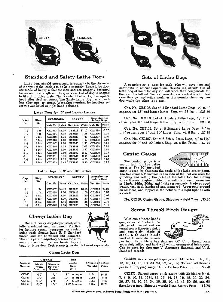
.,,-, ~ ' .. . ....
<;;:.:-..
. . ,
: .
.....
Standard and Safety Lathe Dogs Lathe dogs should correspond in capacity to the diameter
of the work if the work is to be held securely. These lathe dogs are made of heavy malleable iron and are properly designed for maximum strength and long service. Tail of dog is shaped to fit slot in drive plate. The Standard Lathe Dog has square head alloy steel set screw. The Safety Lathe Dog has a headless alloy steel set screw. Wrenches required for headless set screws are listed in right-hand columns.
Lathe Dogs for 13" and Larger Lathes
Cap. Ship. STANDARD SAFETY Wrenches for Safety Dog.
In. Wt. Cat . No. Price Cat. No . Price Cat. No. Price
~ lib. CE3843 $1.05 CE3826 $1.10 CE2385 $0.07
~4 lib. CE3844 1.25 CE3827 1.25 CE2386 0.08 I 2 lb •. CE3845 1.35 CE3828 1.35 CE2387 0.09 1)1 2 lb • . CE384S 1.60 CE3829 1.60 CE2388 0. 10 I V. 3 lb •. CE3847 1.90 CE3830 1.90 CE2389 0.14
I ~ 3 lb • . CE3848 2.05 CE383 I 2.05 CE2389 0.14 2 4 lb •. CE3849 2 .30 CE3832 2.30 CE2389 0.14 2V. 5 lb •. CE3850 2.60 CE3833 2.60 CE2390 0 .22 3 6 lb •. CE3851 2.95 CE3834 2 .95 CE2390 0.22 3V. 7 lb •. CE3852 4.05 CE3835 4.05 CE2390 0 .22 4 9 lb •. CE3853 5 .45 CE3836 5.45 CE2390 0 .22
Lathe Dogs for 9" and 10" Lathes
Cap. Ship . STANDARD SAFETY
In. Wt. Cat. No . Price Cat. No. Price
~8 I lb. CE3837 $0.95 CE3820 $0.95
V. lib. CE3838 1.00 CE3821
~ 2 lb •. CE3839 1.20 CE3822 I 2 lb •. CE3840 1.30 CE3823 1 )1 3 lb •. CE3841 1.45 CE3824 I V. 3 lb •. CE3842 1.85 CE3825
Clamp Lathe Dog Made of heavy drop-forged steel, care
fully machined and hardened. Practical for holding round, hexagonal or rectangular work. Screws have U. S. Standard thread and are hardened and tempered. The nuts permit adjusting screws for minimum projection of screw heads beyond
1.00 1.20 1.30 1.45 1.85
Wrenches for Safety Dogs
Cat . No. Price
CE2385 $0.07 CE2385 0.07 CE2386 0 .08 CE2387 0 .09 CE2388 0 .10 CE2388 0.10
body of lathe dog. Each clamp lathe dog is boxed separately.
Clamp Lathe Dogs
Capacity Size Catalog
Maxi. Distance Lath. Shipping Factory
Number mum Between Us.d Weight Price Opening Screws With
--- ---CEI60 1%" 13 /. '" .. 9' & larger lib. $4.59 CEISI I Ys " 2 )1" 13" Ii larger 2 lb • . 6.11 CEI62 2 ~' 2 3 /. # .. 13" & larger 3 lb •. 7.88 CEI63 3 J1' 3V." 14 v" Ii larger 4 lb •. 10.70
Sets of Lathe Dogs
A complete set of dogs for each lathe will save time and contribute to efficient operation. Having the correct size of lathe dog at hand for any job will more than compensate for the cost of a full set. Two or more dogs of each size will often save time on production work, as this permits changing · one dog while the other is in use.
Cat. No. CE2102. Set of 11 Standard Lathe Dogs, Y2" to 4" capacity for 13" and larger lathes. Ship. wt. 36 Ibs . . . .. $26.50
Cat. No. CE2103. Set of 11 Safety Lathe Dogs, Y2" to 4" capacity for 13" and larger lathes. Ship. wi. 36 Ibs . . ... $26.50
Cat. No. CE2105. Set of 6 Standard Lathe Dogs, %" to 1Y2" capacity for 9 ' and 10' lathes. Ship. wi. 6 Ibs . .... $7.75
Cat. No. CE2107. Set of 6 Safety Lathe Dogs, %" to 1Y2" capacity for 9" and 10' lathes. Ship. wi. 61bs. Price .... $7.75
Center Gauge
The center gauge is a useful tool for the lathe operator. The 60° included angle is used for cbecking the angle of the lathe center point. The two small 60° notches in the side of the tool are used for grinding and setting the point of the lathe tool for cutting screw threads. Engine divided graduations in each corner are in 32nds, 24ths, 2Oths, and 14ths respectively. Made of good quality tool steel, hardened and tempered. Accurately ground on all faces, and lapped in the notches to a light tight fit with a standard.
No. CE650. Center Gauge. Shipping weight 2 0%8 ••. $0.80
Screw ThreaCi Pitch Gauges
With one of these handy gauges you can check the pitches of internal and external screw threads quickly and accurately. Made of steel, with each blade marked to indicate threads per inch. Each blade has standard 60° U. S. thread form accurately milled and held well within commercial tolerances. Can be used for checking V, American National, and U. S. Standard threads.
.CE2188. Ace screw pitch gauge with 14 blades for 10, 11, 12, 13, 14, 16, 18, 20, 24, 27, 28, 32, 36, and 40 threads per inch. Shipping weight 4 ozs. Factory Price ......... $0.70
CE2171. Starrett screw pitch gauge with 30 blades for 6, 7, 8, 9, 10, 11, 11 Y2, 12, 13, 14, 15, 16, 18, 20, 22, 24, 26, 27, 28, 30, 32, 34, 36, 38, 40, 42, 48, 50, 56, and 60 threads per inch. Shipping weight 5 ozs. Factory Price .. . $3.70
Given the proper care, a South Bend Lathe williolt a lifetime. 55

Turning Tool Holders Drop-forged steel, heat
treated and hardened lathe tool holders. Supplied in three styles: straight, right-hand, and left-hand as illuatrated.
Price includes: tool holder with hardened steel set screw, one unground hardened highspeed steel cutter bit, and a hardened drop-forged steel wrench.
Cat. No.
Sia. Lath.
Sia. Shank
Sia. I Ship. I Fact. Cutter Wt. Price
Straight Shank Turning Tool Hold ....
CE847SI CE8468 CE8528 CE853S
9*, Ll T.D, 4 10" I~'" Il-(,'I U'" ~'Il lb. 1 $2.44 9*, Lt. T.D, & 10" %' " Il-(,' ",",,~, 2 lb.. 5 .61 13' I '" 1~' ~" " l-(," 3 lb.. 6.42
14 ~', 16' 4 16-24" ~' " n,· %' x % ' 3 lb.. 7.88
Right-Hand Turning Tool Hold ....
CE847RI CE846R CE852R CE853R
9*, Lt. T .... 4 10" % ' x"'" ",. ,,~' 2 lb.. 5.61 9*, Ll Ten, & 10" 1 %'" Il-(,"I' ~"x ~"Il lb. 1 $2.44
13" ~' x l Yo" ~. x l-(,' 3 lb.. 6.42 14 ~", 16' 4 16-24' %' " 1 % ' ~" x ~" 3 lb.. 7.88
CE847L CE846L CE852L CE853L
Left-Hand Turning Tool Hold ...
9*, Lt. T.D, 4 10" 9*, Lt. T.D, 4 10"
13" 14 ~", 16" 4 16-24'
$2.44 5.61 6.42 7.88
Ilght-Honci
Cutting-off Tool Holders
Cutting-oU tool holders are made of drop-forged Steel, heat-treated and hardened. ~upplied in three st,les: straight, right-hand, and lefthand as illustrated.
Price includes: tool holder, one cutter blade, and wrench. ~ Left-Honcl
Cat. I No.
CE736S
Siz. Lath.
Siaa Shank
Size Cutter I Ship. I Fact.
Wt. Pric.
Straight Shank Cutting-off Tool Hold ....
9*, Ll T.D, 4 10" l-(,' x Il-(,' ~" " .475" 2 lb.. 5.61 CE833S1 CE883S CE884S
9*, Lt. Ten, & 10" I %' x Il-(,'I~"" .595'1 1 lb. 1 $2.89
13" • x l Yo' Yo' x .735' 3 lb.. 706 14 ~", 16' 4 16-24' ~. x )~. Yo' x .870" 3 lb.. 8:86
Right-Hand Cutting-off Tool Hold ...
CE736R 9*, Lt. T.D, " 10" l-(,' x I~' '"',, .475' 2 lb.. 5.61 CE833RI 9*, Ll T .... "Ie' I ~' x Il-(,· I lt. x .595'1 1 lb. 1 $2.89
CE883R 13" ~' " 1 ~' Yo' " .735" ' 3 lb.. 7.06 CE884R 14 ~', 16"" 16-24' %" x 1 ~' Yo' ".870" 3 lb.. 8.86
Left-Hand Cutting-off Tool Hold_
CE736L1 9*, Lt. T.D, "10" I ~" x '~'I~' x .475"1 2 lb.. I $5.61 CE883L 13' ji' x 1~ Yo" x .735" 3 lbe. 7.06 CE884L 14 ~', 16" 4 16-24" %' x 1%' Yo' x .870" 3 lb.. 8.86
Blades for Cutting-off Tool Holders Made from high-speed
steel, heat-treated, hardened, ground on the edges, ready to use in tool holders or 10 in I Tool Holder.
Cat. No. Siaa of Blad. Ship. Wt.
CE876 ~. x .595' " 5' Sou. CEl192 'Az" " .475' x 4 ~. 5 .... CE878 Yo' x .735' x S' 6ou. CE879 Yo' x .870" x 6" 8ou.
Price
$1.36 1.12 1.48 1.94
Ground Cutter Bits for Forged Turning Tool Holders
These cutter bits are made of good quality high speed steel and . are' heat-treated and hardened. . When ordering, be sure to specify the cataloq numbers and the letters designating L AH RO!.d R.CH. L.DH. Th!.t shapes of bits wanted. T~~g Nooe Turning Sid. ing'
F R. H. Sid.
Ground High Speed Steel Cutter Bit.
Size Length Singl. Bit Sat of 6 Bite
~u .... Cutt.r Cat. Ship. Cat. Ship. Fact . nch Inch .. No. Wt. Price No. Wt. Price
~ 2 CEI305 4 00. $0.45 CEI779 10 00. $2.40 2~ CE1313 5 GU. 0 .60 CEI777 10~ ou. 3 .30
% 3 CE1316 5 00. 0 .85 CElTI8 11 GU. 4.70
Ground Cutter Bits for 10 in 1 Tool Holders
High speed steel cutter bits ground for use in lOin 1 tool holder listed on page 58. Made in four shapes: T for turning, H for threading, R for facing on right side of work, and L for facing on left side of work. When ordering single bits be sure to specify shape wanted.
Siaa Length Singl. Bit Sat. of 4 Bite Squ .... Cutter Cat. Ship. Cat. Ship. Fact . Inch Inch .. No. Wt. Price No. Wt. Price ---
g~ ~ 3 Sou. $0.85 CE2776 I lb. $3.20 Yo 4 8ou. 1.75 CE2777 2 lb.. 6.75 % 4 ¥S CE2269 1 lb. 3.40 CE2778 3 lb.. 12.95
Unground Cutter Bits These cutter bits are the
same quality as those listed above but they are not ground.
--------------_.,-' ------ '
They are heat-treated and hardened and are ready for use when sharpened. Specify cataloq number and size when ordering cutter bits.
Unground High Speed Steel Cutter Bit. Catalog Six. Length Shipping Factory Number Squ .... Cutter Waight Price
CE3531 ~. I ' 3ou. $0.14 CE353Z ~. 1 ~' 3ou. 0 . 17 CE3533 ~' 2" 4ou. 0.38 CE3534 ~' 2 ~' Sou. 0.48 CE3S35 's' 3" Sou. 0.10 CE3536 ~. 3~" 1ou. 1.00 CE3537 ~. 4' 12 ou. 1.35 CE3538 %' 4 %' Ilb. 2 .00
Ungro:und High Speed Steel Cutter Bit. in Lot.
Siaa Length Lot of 6 Bite Lot of 24 Bite -Squ .... Cutt.r Cat. Ship. C.t. Ship. Inch Inch. No. Wt. Price No. Wt. Price ------
l-(, 1 . .. . . . . ......... .... .. CE2370 1 lb. $ 3. 10 l-(, I ~ ....... .... .. . .. .. .... Cr.2371 1 lb. 3.75 ~ 2 CEI6Z9 10 GU. $ 1.95 CE237Z 2 lb • . 7.SO
~ 2~ CEI83Z 10~ ou. 2.70 g~~~ 3 lb.. 10. 25 3 CEI633 11 ou. 3.75 4lb.. 14.SO
l-(, 3~ CE2S01 2 lb •. 5.SO CE2375 6 lb.. 21.50 ~ 4 CEZSOZ 3 lb.. 7 .50 CEZ393 13 lb.. 29.00 % 4~ CE2503 4 lb.. 10.95 CE2376 IS lb •. 43.00
Cutter Bit Grinding Gauge For grinding the correct front
clearance, side clearance, front rake, and side rake on lathe tool cutter bits for machining iron and steel. Made of stainless steel. Instructions for using are packed with each gauge.
No. CE2169. Shipping weight Y2 lb. Factory Price . . . . ...... . . . $0.60
56 You con put faith in South Bend.
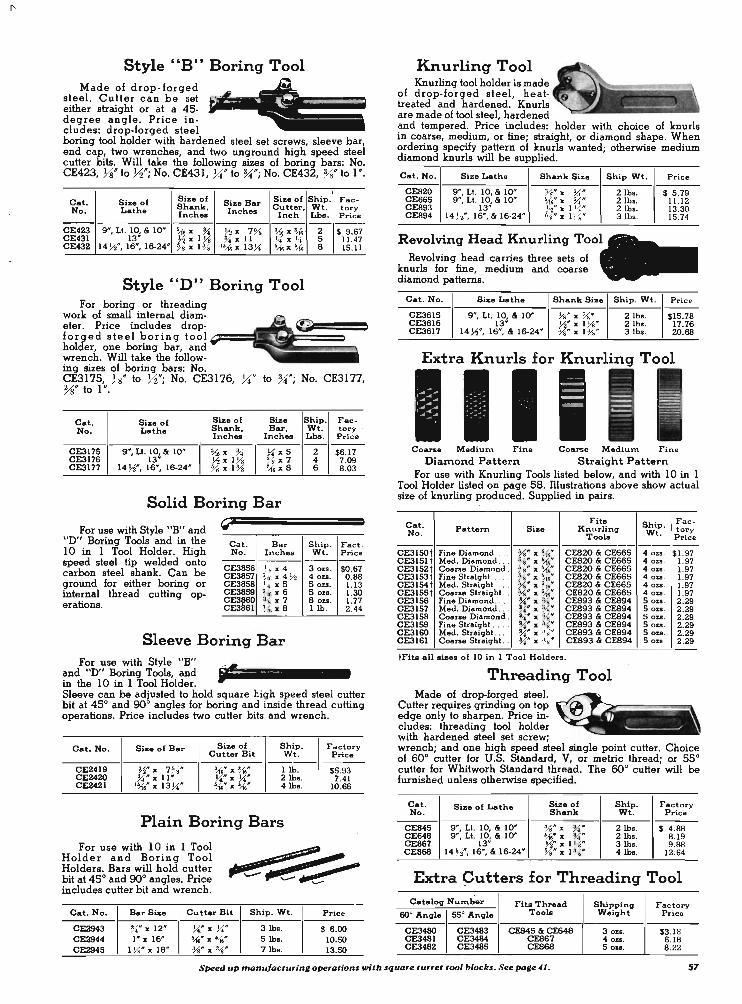
Style "B" Boring Tool Made of drop-forged
steel. Cutter can be set either straight or at a 45-degree angle . Price includes: drop-forged steel boring tool holder with hardened steel set screws, sleeve bar, end cap, two wrenches, and two unground high speed steel cutter bits. Will take the following sizes of boring bars: No. CE423, Ys" to 72"; No. CE431, ~. to %;"; No. CE432, %V to I ".
S ize of Size of Ship. F ae-Cat. Size of S ize Bar No. Lathe Shank. Inches Cutter . Wt. t ory
Inch.s Inch Lbs. Price -- - - -CE423 9", Lt. 10, & 10" 'M " ~ ~ " 7 % ',{. " t? 2 $ 9 .61 CE431 13" Y. "l ti ~ "ll !4' x I .. 5 11.41 CE432 14 ~', 16", 16-24" ;8 X 1 7~ ISM x 13~ ',{,; ,, ',{,; S 15.11
Style "n" Boring Tool For boring or threading
work of small internal diam-13ter. Price includes drop· forged steel boring tool ~=== holder, one boring bar, and wrench. Will take the follow-ing sizes of boring bars: No. CE3175, Ys" to 72"; No. CE3176, ~" to %;"; No. CE3177, %" to I ".
Cat. Size of S ize of Size No. Lathe Shank. Bar,
Inche. Inch ..
CE3115 9 ", LI. 10, & 10" ',{,; " %' )4 " 5 CE3176 13" ~ " 1% % ,,7 CE3177 14 n*, 16*, 16-24- % " 1% i{. " S
Solid Boring Bar
For use with Style "B" and "D" Boring Tools and in the 10 in 1 Tool Holder. High speed steel tip welded onto carbon steel shank. Can be ground for either boring or internal thread cutting op-erations.
" Cat. No .
---CE3856 CE3851 CE3858 CE3859 CE3860 CE3861
B a r Inches
H x 4 ~J6 X 4M J", x 5 ~ x 6
8 x 7 i{ti x S
Sleeve Boring Bar For use with Style "B"
and "D" Boring Tools, and in the 10 in 1 Tool Holder.
Ship. Fae-Wt . tory . Lbs. P ric e - - ---
2 $6.11 4 1 .09 6 8.03
Ship. F act. Wt. P ric e --
3 0 Z8 . $0 .61 4 OZS. 0 .88 5 OZS. 1. 13 50%8. 1.30 80u. 1.11 1 lb . 2.44
Sleeve can be adjusted to hold square high speed steel cutter bit at 45° and 90° angles for boring and inside thread cutting operations. Price includes two cutter bits and wrench.
Cat. No. Size of Bar Size of Ship. Cutter Bit W t.
----CE2419 ¥2" ][ 7~ 8" ~" ][ ;{t 1 lb. CE2420 ~ .. ][ 11* . ~" ][ U" 2 lb • . CE2421 I',{,;" " 13 )4" ~~'" x ~* 4 lb •.
Plain Boring Bars
For use with 10 in 1 Tool Holder and Boring Tool Holders. Bars will hold cutter bit at 45° and 90° angles. Price includes cutter bit and wrench.
Cat. No. Bar Size Cutter Bit
CE2943 UI" ][ 12" ~" " )4" CE2944 1" x 16.11' ~.II' x ~.II'
CE2945 1 ~" " IS- % .11' x ~ .II'
Ship . Wt.
3 lb • . Sib • . 7 lb • .
Factory P rice
$5.93 1 .41
10.66
P ric e
$ 6 .00 10. SO 13.SO
Knurling Tool Knurling tool holder is made
of drop-forged steel, heattreated and hardened. Knurls are made of tool steel, hardened and tempered. Price includes: holder with choice of knurls in coarse, medium, or fine; straight, or diamond shape. When ordering speciJy pattern of knurls wanted; otherwise medium diamond knurls will be supplied.
Cat . No . Size Lathe Shank Size Ship Wt . Price
CE820 9", Lt. 10, & 10" Ys" x %'''' CE665 9", LI. 10, & 10" ~" x %''' CE893 13 - ~" x l Ys" CE894 14 H", 16", & 16·24" %" x 1%"
Revolving Head Knurling Tool Revolving head carries three sets of
knurls for fine, medium and coarse diamond patterns.
2lbs. $ 5.19 2 lb • . 11 .12 2lbs. 13.30 3 Ibs. 15.14
Cat. No. Sixe Lathe Shank Size Ship. Wt . P rice
CE3615 9", LI. 10, & 10" ~" x X" 2 lb • . $15.18 CE3616 13" ~" x l Ys" 2 lb • . 11.16 CE3611 14 ~", 16", & 16-24" %" x 1%" (3 lb •. 20 .68
Extra Knurls for Knurlinq Tool
I Coarse Medi ulT\ F ine Coarse Medium. F ine
DiaInond Pattern Straight Pattern For use with Knurling Tools listed below, and with 10 in 1
Tool Holder listed on page 58. Illustrations above show actual size of knurling produced. Supplied in pairs.
Cat. Fits Pattern Size Knurling No . Tools
CE31SO t Fine Diamond . .. . %" x ~M" CE820 & CE665 CE3151 t Med . Diamond .. %.II' ][ ~" CES20 & CE665 CE3152 t Coa rse Diamond . ~ 8" x liM" CES20 & CE665 CE3153 t Fine Straiqht . .. . . %" x ~e" CE820 & CE665 CE3154 t Med. Straiqht . ... VB" X ~161f CE820 & CE665 CE3IS5 t Coarse Straiqhl. . %If X ~" CES20 & CE665 CE3156 Fine Diamond . . . . ~" x 8" CES93 & CES94 CE3157 Med. Diamond ... ~{.II' X Ys" CE893 & CE894 CE3158 Coarse Diamond . ~" 'x %'" CE893 & CE894 CE3159 Fine Straiqht . .. ~" x ~" CE893 & CE894 CE3160 Med. Straiqhl. .. ~" x ~t s IP CE893 & CES94 CE3161 Coarse Straiqht .. ~It X ~8.11' CES93 & CES94
tFits all .ixe. of 10 in 1 Tool Holders .
Threading Tool Made of drop-forged steel.
Cutter requires grinding on top edge only to sharpen. Price in· cludes: threading tool holder with hardened steel set screw;
Ship . F ae · tory W t . P rice
40%5 . $1.97 40%5 . 1.91 401.8. 1.97 40%9. 1.97 4 0%5. 1.91 40u . 1.97 50%8 . 2 .29 50%.8 . 2 .29 50&9. 2 .29 50zs. 2.29 50%.8. 2.29 SOZ8 . 2.29
wrench; and one high speed steel single point cutter. Choice of 60° cutter for U.S. Standard, V, or metric thread; or 55° cutter for Whitworh Standard thread. The 60° cutter will be furnished unless otherwise specified.
Cat . Size of Lathe Size of Ship. Factory No . Shank Wt. P rice
CE845 9", LI. 10, & 10" Ys" x U " 2lbs. $ 4.88 CE648 9 ", Lf. 10, & 10" 5MIP
X %' '' 2 lb • . 8 .19 CE861 13" Yo" " 1%" 3 lb • . 9.68 CE868 14 J-f", 16", & 16-24" %" " 1% " 4 lb • . 12 .64
Extra qutters for Threading Tool Cataloq Number Fits Thread Shippinq Fac tory
60° Angle 55° Angle Tools Weight P ric e
CE3480 CE3483 CE845 & CE648 3 oz • . $3.18 CE3481 CE3484 CE867 40u. 6.18 CE3482 CE3485 CE868 501:8. 8 .22
S~ed up manufactu,ing o~,ations with squo,e turret tool blocks. See page 41 . 57

Chuck and Tool AssortInents The chucks and tools in the assortments listed are recom
mended for use with the various sizes of South Bend Lathes. They include the basic equipment required for the average shop for general machine work, such as turning, boring, drilling, cutting-oH, chucking, etc.
ll-Tool Assortment with Independent Lathe Chuck
Item Oeacription
4-Jaw Independent Lathe Chuck litted to lathe. Sise. : 6 in . on 9' and 10' Lathe.; 7 ~ 'in. on 13' Lathe; 9 in . on 14~' Lathe; 10' on 16' and 16-24' Lathe • .
2 Jacob. 3·Jaw Drill Chuck. Sis .. : ~ in. on 9' and 10' Lath .. ; ~ in . on 13' and 14 ~' Lathe. ; I in. on 16' and 16-24' Lath ...
3 Arbor Fitted to above Drill Chuck. 4 6 Ground Cutter Bib for Toel Holder. 5 Borinq Toel Holder, Style "B". 9' and Liqht Ten Lathe. take
Style " 0". 6 Cuttinq.off Toel Holder, Riqht.Hand.
7·10 4 Melleable Lathe Doq • . Size . : ~', ~', I' and I ~'. 11 Straiqht Shank Toel Holder.
Complete Assortments as Listed Above
Cat. No. Size Lathe Ship . Wt.
CL2890NK 9' & Light Ten 28 lb •. CL2890L 10' 35 lb •. CL2890Q 13' 70 lb •. CL2890M 14 W 75lb,j. CL2890H 16' & 16-24' 80 lb •.
10 in 1 Tool Holder The 10 in 1 Tool
Holder replaces the conventional tool post and various tool holders ordinarily used for general lathe work. It provides rigid support for turning, boring, threading, and cut-oH tool bits. In addition, it is equipped with a self-aligning knurling head having No. CE3151 medium dia
F actory Price
$ 69 .50 llS.OO 140.00 163.00 IB6.00
mond knurls. Screw adjustments for tool height are easily made, and they stay put. No readjustment is required when replacing tools. This tool block can he adapted to fit other makes of lathes. See pages 56, 57 and 59 for cutter bits, boring bars, cut-oH blades, and extra knurls.
Size Holda Holda Holda Ship. Fae-Catalog Lathe Cutter Boring Cut-off Wt. tory Number Inch .. Bite Bara Blade. Lb • . Price
Inch Inch .. Inch
CEI413NK 9&Lt. Ten Ys " Ys Ys to %' l-(, ,, .595 5 $13.50 CEI413R 10 Ys ,, % Ys to %' !-6 " .595 5 14.50 CEI413T 13 J.i " ~ ~ to 1 ~ J1 " .735 7 17.25 CE1413F 14 ~ Ys ,, % to 1 ~ J1 " .870 10 20.00 CE1413H 16& 16-24 Ys " % ~ to 1 ~ Yo " .870 10 20.75
20-Tool Assortment for 9" and Light Ten Lathes
This is a more complete assortment than those listed at left, and consists of the following equipment: .
Item
I 2 3 4
5 6 7 8 9
10 11-12
13 14 15 16 17 18 19 20
Cat. No.
CL4OO6NK CL300SNK CE1201 CE2302
CE847S CE847R CE847L CE833R CE833S CEI779 CEI629
CE317S CE423 CE3837 CE3838 CE3839 CE3940 CE3941 CE3842
Oeacription
6' Four-Jaw Independent Lathe Chuck, litted. 5' Three-Jaw Univeraa! Lathe Chuck, fitted. Jacob' . Thr .. Jaw Drill Chuck, ~'capacity. Taper Shank Arbor (No.2 M.T.), fitted to Drill
Chuck. Straiqht Shank Turning Toel Holder. Riqht.Hand Turning Toel Holder. Laft-Hand Turninq Toel Holder. Right-Hand Cutting-oH Toel Holder. Straiqht Shank Cutting-off Toel Holder. Set (6) Ground Cutter Bib for TUrnin", Toela. Two Seb (6) Unground Cutter Bib for Turning
Toela. Style "0" Boring Toel Holder. Style "B" Borinq Toel Holde r . Yo' Standard Malleable Lathe Doq. ~' Standard Malleable Lathe Doq. ~' Standard Melleable Lathe Doq. I Standard Melleable Lathe Doq. I ~' Standard Malleable Lathe Doq. I ~'Stand"rd Melleable Lath. Doq.
CL2970NK. Twenty Tool Assortment as listed above for 9 ' or Light Ten Lathes. Shipping weight 52 lhs . ....... . . $152.50
ll-Tool Assortment With Universal Chuck For 9-inch and Light Ten Lathes Only
This assortment is exactly the same as the No. CL2890NK assortment listed at left, eIcept that a No. ' CL3005NK, 5' 3-jaw Universal chuck is supplied in lieu of the 6 ' 4-jaw Independent chuck.
CL2960NK. Eleven Tool Assortment with Universal Chuck for 9-inch and Light Ten Lathes. Ship. wt. 20 lhs. Price . . $89.50
•
II
IIII~ 10 in 1 Tool Holder Kit
You can save money by purchasing this 10 in 1 Tool Holder Kit complete with boring bar, cut-oH blade, and set of four ground high speed steel cutter bits. Price also includes knurling head, bolt clamp, and all other equipment regularly supplied with the 10 in 1 tool holder.
For specifications of tool holder see column at left. Descriptions and illustrations of cutter bits, boring bars, cut-oH blades, and extra knurls, see pages 56, 57 and 59.
Item. Included in Ki t Fac-Catalog Size of Ship. tory
No. of Kit Lathe Cutter Boring Cut-off Weight Price Bite Bar Blade ------------
CE2930NK 9' & Lt. Ten CE2776 CE2419 CEB76 7 lb •. $23 .00 CE2930R 10" CE2776 CE2419 CEB78 7 lb •. 24.00 CE2930T 13" CE2777 CE2420 CE876 12 lb •. 32.00 CE2930F 14 J.i" CE2778 CE2421 CE879 lalba. 44.00 CE2930H 16" & 16-24" CE2778 CE2421 CE879 18lba. 45.00
58 It pays to /uJlle a full set of collets. See pa,e 36.
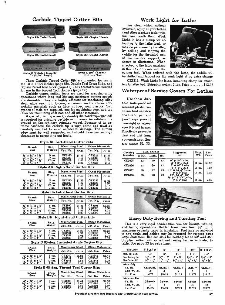
' I
Carbide Tipped Cutter Bits
.......... - ._-- -< ' " ,- ,
- '- .... - '- \.. ~.\ \ \~
Style AL (Left-Hand)
Style D (pointed Nose SOo Inchaped Anllle)
Style AR (Rillht-Hand)
Style BR (Rillht-Hand)
Style E (60° 'l'hread) Cuttinll Tool
These Carbide Tipped Cutter Bits are intended for use in the 10 in 1 Tool Holder (page 58), Double Tool Cross Slide, and Square Turret Tool Block (page 41) . They are not recommended for use in the Forged .Tool Holders (page 56).
Carbide tipped cutting tools are used for manufacturing operations where long tool life and maximum cutting speeds are desirable. They are highly efficient for machining alloy steel, alloy cast iron, bronze, aluminum and abrasive nonmetallic materials such as fibre, rubber, and plastics. Two grades of tools are supplied, one for machining steel and the other for machining cast iron and all other materials.
A special grinding wheel (preferably diamond impregnated) is required for grinding carbide as it cannot be satisfactorily ground on the ordinary grinding wheel. Because of its extreme hardness, the carbide tip is very brittle and must be carefully handled to avoid accidental damage. The cutting edge must be well supported and should have just enough clearance to permit it to cut freely.
Style AL Left-Hand Cutter Bits
Shank Ship. Machining Steel Other Material. Size Weillht Cat. No. Price Cat. No. P rice
"" " "" " 2 ~' Sou. CE3320 $1.32 CE3325 $ 1.25 '''',, ~' x 3' 70&8. CE3321 1.57 CE3326 1.50 ~'x ~'x 3 Y.' 12·0 ... CE3322 1.83 CE3327 1.74 % 'x % 'x4' l ib. CE3323 2 .26 CE3328 2.15
Style AR Right-Hand Cutter Bits
Shank Ship. Machininll Steel Other Material. Size Weillht Cat. No. P ric e Cat. No. P ric e
W x W x2W 50&8. CE3330 $1.32 CE3335 $1.25 'Ua' ][ u.' I 3 700 . CE3331 1.57 CE3336 1.50 ~'x ~'x 3 Y.' 12 ou. CE3332 1.83 CE3337 1.74 Ya' z: %' x 4' lib. CE3333 2.26 CE3338 2 .15
Style BL Left-Hand Cutter Bits
Shank Ship. Machining Steel Other MateriaIa Sis. Weillht Cat. No. Pri c e Cat. No. Price
"" x % ' x 2Y.' . 5 OJ'S. CE3590 . $ 1.32 CE3595 $1. 25 '' '' x ~'x 3' 70&8. CE3591 1.57 CE3S96 1.50 ~'x ~'x3 ~' 12 OKS. CE3592 1.83 CE3597 1.74 %.'x % 'x4' 1 lb. CE3593 2.26 CE3598 2 .15
Style BR Right-Hand Cutter Bits
Shank Ship. Machining Steel Other MateriaIa Size Weillht Cat. No. Pric e Cat. No . P ric e
Yo' x Yo' x 2 ~' Sou. CE3550 $1.32 CE3555 $1.25 7",,- x 7.10 ' x 3' 70&8. CE3S5l 1.57 CE3556 1.50 ~' x ~'x 3 ~' 12 on. CE3552 1.83 CE35S7 1.74 %' ][ 78 ' x 4 ' 1 lb. CE3S53 2.26 CE3556 2.15
Style D 8O-deq. Included Angle Cutter Bits
Shank Ship. Machininll Steel Othe.r Materials Size Weillht Cat. No. P ric e Cat. No. Pric e
"" x "" x 2 ~' Sou. CE3340 $1.52 CE3345 $1.44 '' '' x ~' x 3' 70Z8. CE3341 1.83 CE3346 1.73 ~'x ~'x3 ~' 12 QU. CE3342 1.88 CE3347 1.79 ~. ]I: %" x 4' lib. CE3343 2.41 CE3346 2 .30
Style E 6O-deq. Thread Tool Cutter Bits
Sha.nk Ship. Machininll Steel Othar Materiala Size W.illht Cat. No. P rice Cat. No. P r ice
"" x "" x 2 ~' Sou. CE3390 $1.44 CE3394 $1.38 "'" x 7...{e ' X 3' 70 ... CE3391 1.65 CE3395 1.57 ~'x ~'x 3 ~' 120u. CE3392 1.76 CE3396 1.67 %'][ Ys . x 4' lib. CE3393 2.30 CE3397 2 .19
Work Light for Lathe For clear vision without
eyestrain, equip all your lathes .(and other machine tools) with this new South Bend Work Light. It has a clamp for attaching to the lathe bed, or may be permanently installed by drilling and tapping the saddle for the threaded end of the flexible support, as ' shown in illustration. When attached to the lathe carriage in this way it travels with the cutting tool. When ordered with the lathe, the saddle will be drilled and tapped for the work light at no exira charge
CE2815. Work Light for lathe, including clamp for attach-ing to lathe bed. Shipping weight SIbs. Price ....... . . $12.95
Waterproof Service Covers For Lathes
Use these durable waterproof oil resistant plastic machine tool service covers to protect your equipment overnight or whenever it is not in use. Effectively prevents dust and dirt from accumulating. See also pages 70, 73.
CatalOlJ Size. Inch.s Number Wdth. L!Jth. ---CE2695 32 48
CE2696 32 60
CE2697 38 72
CE2698 38 96
Ht.
17
17
25 '
25
SUIlIl .. ted Ship. F ac . for Wt. Pri c e
---9' & 10' Lathe, 3 ' & 3 Y.' Bed 2 lb • . $2.95 9' & 10' Lathe 4' 814 ~' Bed 3 lb •. 3 .25
13' & 14 Y.' Lathe, 4' & 5 ' Bed 3lba. 5 .25
13', 14 ~', IS', 16-24' & 2·H Lathe,
S' & 7' Bed 31bs. 7.50
Heavy Duty Boring and Turning Tool This is a very rigid combination tool for boring, turning,
and facing operations. Holder takes bars from %' up to maximum capacity listed in tabulation. Tool may be swiveled to any angle and holder may be reversed for turning exira large diameters. Bar has slots for holding bit at 90° and 45°. Supplied either with or without boring bar, as indicated in table. See page 57 for exira bars.
Size Lathe 9' &LL Ten 10' 13' 14V.' 16'&16-24'
Max. Bar Cap. ~ .. ~' IW l V.' Iv.' Size Boring Bar ~'x IZ' ~' x 1Z' I' x 16' I Ys' x 18' IYs' x 18' Size Cutter Bit ~'x ~' U'x ~ .. ~'x ~' "" x "," "" x %' Holder Only
Cat. No. CE3677Nf< CE3677R CE3677T CE3677F CE3677H Ship. WI. lb •. 3 3 5 7 7 Fac, Price $8.75 $10.25 $12.25 $1 3.75 $15.25
Holder and Bar Cal. No. CE469NK CE469R CE469T CE469F CE469H Ship. WI. lb •. 8 8 14 15 18 Fac .. Price $14.75 $16.25 $22.75 $27.25 $28.75
Practicol attachment. increase tlu! usefulnes. of your lot""'. 59

12" Precision Level
Precision tolerances can be maintained only when the lathe is properly leveled. With this 12" · sensitive precision level, a lathe or other machine can be properly installed and leveled. The level has a ground and graduated vial mounted in a twelve inch cast iron frame with machined base having a V-way for leveling shafts. It has been carefully designed to provide just the right degree of sensitivity for quick and accurate leveling. Can be used only in horizontal position. We recommend that every shop be equipped with one of these levels.
Cat. No. CE2218. Precision Level. Packed in wooden case. Shipping weight 5 lhs. Factory Price ... . . . . ..... . . ... $12.50
Chuck Wrenches
Catalog Sise Shipping Factory Number Square Weight Price
CE2748 .277" 2 lb • . $1.90 CE2742 .297" lib. 1.65 CE2743 .375" 2 lb • . 1.90 CE2749 .400" 2 lb •. 1.90
l-
'D CE2744 .420" 2 lb • . 2.SO CE2746 .570" 2 lb • . 2.SO
Sizes of Wrenches Required for Various Sizes of Chucks
Cat. No. Sisa of ~ckf Siz. Cat. No. of of Chuck Chuck Square Required Wrench
CL4OO6NK 6" Independent .297" CE2742 CL4206NK 6" Independent .297" CE2742 CL4006L 6" Independent .297" CE2742 CL4206LQ 6" Independent .297" CE2742 CL4207LQ 7W Independent .420" CE2744 CL42090 9" Independent .420" CE2744 CL4207MH 7W Independent .420" CE2744 CL4209MH 9" Independent .420" CE2744 CL4210MH 10" Independent .420" CE2744 CL4212H 12" Independent .420" CE2744 CL300SNK 5" Universal .277" CE2748 CL3505NK 5" Univenal .375" CE2743 CL3506NK 6" Universal .400" CE2749 CL300SL 5" Universal .277" CE2748 CL3SOSLQ 5" Universal .375" CE2743 CL3506LQ 6" Universal .400" CE2749 CL3507Q 7W Universal .400" CE2749 CL3505MH 5" Universal .375" CE2743 CL3506MH 6" Univenal .400" CE2749 CL3507MH ~W Universal .400" CE2749 CL3509MH Universal .570" CE2746
Single End Wrenches ~------') II
Catalog Opening Length Thien_ Shipping Factory Numb ... Weight Price
CE26S7 ''''" S ~" 2'..&. ... 7 oz • • SO.80 CE2658 1~'" S ~" 21,.(. ... 8 au. 0.80 CE2670 Yii" 6 % " )4" 1 lb. 1.36 CE2671 1 'Ai" 8 ~" ''''" I lb. 1.92
Tool Post Wrenches c:= · 1
Catalog Sise Lathe Open. Cloeed Lgth. Thick- Ship. Fact. Nu.nber End End Wt. Price n_
------------CE2650NK go %" % " 4" CE2650R 10" ~: ~" 4" CE2650T 13" ~" 6" CE2650FH 14 ~", 16", "
16-24" !.11" !.11" 6"
Tailstock Wrenches
Catalog Open- Ex-Si,.e Lathe treftle Number ing Lgth.
---CE2653NK 9" I'M" S~r CE2653R 10" 2'A!" 6 , " CE2653T 13" l U," 7 ?1j" CE2653FH 14 ~", 16", & l~" 9 ~'
16-24"
Spanner Wrenches
Catalog Circle Extreftle Pin No. Diameter Length Size
CE2739 u,,'" 4" !.11" CE2740 1 ~" 5" U." CE2734 2 )4" 6 ~" I~" CE2735 2~' 7 ~" It / · ," CE2736 3" 8" ''''" CE2737 3~" 8 ~" 1~" CE2736 3%' go I ~'
Hollow Hexagon Head Set Screw Wrenches
Ys '" 4 OA. SO.80 %- 6 ou. 0.95 !.11" 1 lb. 2.20
!.11" 1 lb. 2 .20
Thick- Ship. Fae-tory n_ Wt. Price
---------~" 6ou. SO.65 Ys '" 1 lb. 0 .75
• 1 ~. 2 lb • . 1.10 I" 2 Ibo. 1.35
@II
Shipping Factory Weight Price
5 0:&1. SO.80 6ou. 1.10 1 lb. .80 1 lb. 1.10 1 lb. 1.25 1 lb. 1.30 2 Ibo. 1.55
( !
Catalog SI_ Extreme Extreme Shipping Factory Number Hex. Length Height Weight Price
CE2391 ~: 3 ~" ~" 3 0:&1. SO.07 CE2392 2 ""'" ?1j" 3010. 0.07 CE2395 U," 2 '\16" I" 3 0:&1. 0 .07 CE2386 ~" 2 % " 1 %" 4 au. 0 .08 CE2387 U," 2~" 1)4" 40u. 0.09 CE2398 h" 3~" 1% " 4 oaa. 0.10 CE2389 ~" 4 'Ai" 1''''" 4 0:&1. 0.14 CE2390 %" 4~" 1'~" 6 0:&1. 0.22
Double End Wrenches
Catalog Large Sftla11 Length Thick- Shipping Factory No. Opening Opening n ... Weight Price
----CE2655 ~" % ' 4 ?1j" CE2656 25.-6. ~" 6 ~"
Socket Wrench CE275O. Socket Wrench for nut ~"
square. Fits stroke adjustment nut on South Bend 7" Shapero Ship. wt. 1 ~ Ibs. Factory Price . . .... .. .. ........ :ti2.0S
Open End Box Wrench
---)4" 80 ... SO.72 Il,f* 1 lb. 1.94
" ~. : 1 i9' • ..;# : ,
~======:()O :r?
CE267S. Open End Box Wrench. Ys" opening, Ys" close ~"thick, lOY2"long. Ship. wt. 1 lh. Factory Price . . .. .. $2.82
60 Two tool • .. re better tluln on_get on utro tool po.t for ettery 14the. See poge 39.

~.~v~ .. u~ ~'.'
ENGLISH SCREW THREADS
Right-Inde,. Chart Showinq English Screw Threads Cut with English Transposing Gears
.... ~ • ,,, d.t \ ~ . ...
Left-South Bend Lathe Equipped with English Trans .. posing G.ar s
English Transposing Gears For Cutting English Screw Threads
Right-hand and left-hand English screw threads ranging from 4 to 80 threads per inch, as listed in the index chart above, can be cut (in addition to the regular metric pitches) on any size or type of South Bend Lathe having a metric lead screw, when equipped with a set of English transposing gears.
When lathes are ordered with English transposing gears, the graduated collars on the tailstock spindle, the cross-feed screw, and the compound rest screw can be supplied to read in the English system, or in the metric system, as desired.
English Transposing Gears Ordered With Lathe
With English With Metric Sise of Lathe Graduations Graduations
Cat. No. Price Cat. No.
9" Model A CL2288NK $13.50 CL2284NK 9" Model B CL22S3N IS.OO CL2255N 9" Model C CL22S4N IS.OO CL22S6N
Li\lht Teu Model A CL2288NK 13.50 CL2284NK Li\lht Teu Model B CL22S3K 17.00 CL2255K Light Teu Model C CL2254K 17.00 CL22S6K 10" Quick Change CL2288R 4S.00 CLZZ84R 13" Quick Change CL2Z88T 50.85 CLZZ84T 14~" QUick Chan\le CLZZ88F 58.15 CL2284F
IS*, 16-24*, '" 2.H Q .C. CL2288H 63.00 CLZZ84H
English Transposing Gears Ordered Separate From Lathe
Siae of Lathe Ship. Wt.
9* Model A 8 lb • . 9" Model B 21 Ibs. 9" Model C 21 lb •.
Light Teu Model A 8 lb •. Light Teu Model B 21 lb • . ~ht Teu Model C 21 lb • . 1 Quick Chanlle 51 lb •. 13* Quick Chan\le 73 lb •.
14 ~* Quick Chan\le 121 lb •. IS*, 16-24", '" 2-H Q.C. S5 lb • .
Metric Thread Dial This attachment saves much
time when cutting long screw threads. Instead of reversing the lathe to return the cutting tool to the starting point, the half-nuts may be opened and the carriage moved quickly by hand. The graduated dial shows when to engage the halfnuts so the cutting tool will follow the original cut.
Cat. No.
CLaaaaNK CLIZ83N CLIZ84N CL2289NK CLIZ83K CLIZ84K CL2289R CLZZ89T CL2289F CLZZS9H
Pric e
$13.50 IS.OO IS.OO 13.50 17.00 17.00 4S.00 50.85 58. 15 63.00
Price
$13.50 21.75 21.75 13.50 23.00 23.00 63.55 69.70 78 .90 91.20
Cat. No. CL2265NK. Metric Thread Dial for 9" and Light Ten South Bend Lathes with metric lead screw. Shipping weight 3 Ibs. Factory Price . . . . . . . . . . . . . . .. $18.25 Note: See pa\le 50 for En\lli.h thread dial • .
METRIC LATHES
All South Bend Lathes can be supplied in the metric system, with metric lead screw and gearing for cutting standard pitches of metric screw threads, and metric cross-feed and compound rest feed screws having micrometer collars with metric graduations. The tailstock spin· dles and taper attachment are graduated in both the English and metric systems. Except for these features, the metric lathes are identical with corresponding models having English gearing and graduations. Write for complete information.
"" fI ( '~ "'M~PC~'M~ ~I "'II c .. ,, ~, " ·". ,' 10 ..... , .,_, _.,. _", .
Left-South Bend Lathe Equipped with Metric Tranepoeing G.are
Metric Transposing Gears For Cutting Metric Screw Threads
Right-hand and left-hand metric screw threads ranging from 6 mm pitch to 0.20 mm pitch, as listed in the index chart above, can be cut (in addition to the regular English pitches) on any size or type of South Bend Lathe having an English lead screw, when equipped with set of metric transposing gears.
When lathes are ordered with metric transposing gears, the graduations on the tailstock spindle, the cross-feed screw, and the compound rest screw can be supplied to read in the metric system, or in the English system, as desired. Catalog numbers listed below apply to equipment for current models of lathes only.
Metric Transposing Gears Ordered With Lathe
With En\lli.h With Metric SiBe of Lathe Graduations Graduations
Cat. No. Price Cat. No. Price
9' Model A CL1955NK $13.50 CL1941NK $13.50 9 ' Model B CL2248N 16.00 CL2247N 16.00 9' Model C CL2261N 16.00 CL2263N 16.00
Li\lht Ten Model A CLI955NK 13.50 CLI941NK 13.50 Li\lbt Ten Model B CL2248K 17.00 CL2247K 17.00 Li\lht Ten Model C CL22SIK 17.00 CL2263K 17.00 10' Quick Chan\le CLI955R 50.75 CL1941R 50.75 13' Quick Chan\le CLI955T 56.75 CL1941T 56.75 14~' Quick Chan\le CL1955F 64.00 CL1941F 64.00
IS', IS-24', & 2-H Q. C. CLI955H 69.50 CLI941H 69.50
Metric Transposing. Gears Ordered Separate From Lathe
Size of Lathe Ship. Wt. Cat. No. Price
9' Model A 8 lb •. CLI957NK $13.50 9' Model B 21 lb •. CLl9SZN 21.75 9' Model C 21 lb •. CLI96IN 21.75
Li\lht Ten Model A 8 lb •. CL1957NK 13.50 Light Ten Model B 21 lb • . CL19S2K 23.00 Li\lht Ten Model C 21 lb • . CLI961K 23 .00 10' Quick Chan\le 51 lb •. CLI957R 64 .00 13' Quick Chan\le 73 lb •. CLI957T 70.25 14 ~' Quick Change 121 lb •. CLI957F 78 .75
IS', 16-24', & 2·H O.C. S5Ib •. CL1957H 91.00
For long, troubk-free service, lubricate your machinery regularly with the correct grade of oil. See page 51. 61

J. I. C. Electrical Equipm.ent South Bend Lathes 10" swing and larger can be supplied
with electrical equipment manufactured to Joint Industry Committee of Automotive Industry standards as listed below.
Totally Enclosed Single-Speed Motors To Meet J . 1. C. Standards
Cat. No . H .P . Phase Cycle Volts Factory Price
CE61SO U 3 60 220/ 440 $ 60.00 CE6151 I 3 60 220/ 440 93.00 CE6152 I ~ 3 60 220/ 440 109.00 CE6153 2 3 60 220/ 440 131.00
Non-Fusible Control Equipment Consisting of one combination magnetic reversing line
starter, size 1, with fused dual voltage transformer for low voltage control, overload protection and non-fusible disconnect, all in NEMA type 12 enclosure. Also one pushbutton station, forward, reverse, stop, in oil tight enclosure for surface mounting. CE6l54. Non-fusible Electrical Control Equipment to J. 1. C. standards. Price . . . .. . . . .......... $186.00
Fusible Control Equipment Consisting of one combination magnetic reversing line
starter, size 1, with fused dual voltag~ transformer for low voltage control , with overload protection and with fusible disconnect, all in NEMA type 12 enclosure. Also one pushbutton station, forward, reverse, stop, in oil tight enclosure for surface mounting. CE6155. Fusible Electrical Control Equipment to J. I. C. standards. Price . . . . . . . . . . . . . ... $198.00
Circuit Breaker Control Equipment Consisting of one combination magnetic reversing line
starter, size '1, with fused dual voltage transformer for low voltage control, overload protection and circuit breaker, all in NEMA type 12 enclosure. Also one pushbutton station, forward, reverse, stop, in oil tight enclosure for surface mounting. CE6156. Circuit Breaker Electrical Control Equipment to J. I. C. standards. Price . . . . .. $219.00
Fitting and Connecting Equipment Labor and material for fitting and connecting J. 1. C.
electrical equipment to lathe, including special stand for mounting linestarter to 1. 1. C. standards are extra and will be supplied as follows: CE6l51. Mounting J. I. C. Electrical Equipment on 10" Underneath Motor Drive Bench Lathe. Price . . . . . . $53.00 CE6158. Mounting J. I. C. Electrical Equipment on 10' Under-neath Motor Drive Floor Lathe. Price , ................ $51.00 CE6l59. Mounting J. I. C. Electrical Equipment on 13" Underneath Motor Drive Lathe. Price . . .... $51 .00 CE6160. Mounting J. 1. C. Electrical Equipment on 14 ,Y2" or 16" Underneath Motor Drive Lathe. Price . . ... $52.00 CE6161. Mounting J. I. C. Electrical Equipment on 16-24" Underneath Motor Drive Lathe. Price . . . .. $53.00
M otor s and C ontrols Motors are listed in tabulation No. 1, page 63. Controls·
are listed in tabulations Nos. 2, 3, and 4 . The control equipment required for each size and type of motor is listed on the same line with the motor.
Two-speed motors are listed for 10-inch and larger lathes only. These motors have two forward speeds and two reverse speeds which with the cone pulley and back gears of the lathe, provide 12 to 24 spindle speeds.
Drum switch controls listed in Table No.2 are optional for }:I h.p. and larger motors operating on 230 volts or less. Resistance panels are included in the prices of controls for D.C. motors %: h.p. and larger.
Pushbutton operated linestarter controls listed in Table No. 3 are required for all motors operating on currents higher than 230 volts. These controls are optional for all other motors !~ h.p. and larger. Pushbutton controls provide overload and low voltage protection. For currents above 230v., transformer reduces pushbutton current to 110 volts. Necessary resistance panels are supplied for D.C . motors %: h.p. and larger. . ......... n
1----,.' --I --- . ,
CETI' Drum Control Switch 01 CE790 Drvm Control Switch as mount-mounted on 9 " Bench Lath. ed on 10 " and larger Floor Loth ••
Pushbutton Control Swifc" 'or lingl. Pushbutton Control Switch Jo, two-speed rever.ing motor speed lingle winding moto,
PUlhbuHon Control Switch lor two- Lln .. larter Control Equipment lor two-speed double Winding motor speed motor
Drum Switch Control for 13 ' Control Equipment for 2·H Tu"et lathe Turret lathe
62· Equip each lathe with a South Bend knock-out bar for removing centers. See page 44.

+
Motors and Controls for Lathes Reversing motors are recommended for
South Bend Lathes because they permit reversing the lathe spindle for tapping, thread cutting, and similar operations. All motors listed below are of the instant reversing type with the 13xception of Cat. No. CE3256B, which is a start-stop reversing motor. Single
phase A.C. motors are capacitor type with the exception of CE3256B, which is a split-phase start-stop reversing type motor. For additional information on motors and controls, see page 62. Prices of motors and controls for current characteristics not listed will be quoted on request.
Current MOTORS CONTROLS FOR MOTORS
511: ••• Lathe
14~-lnch I 15-lnch 15-24-lnch ond 2-H
16-lnch, 16-24-lnch
ond 2-H
U~ -Inch IS-Inch
16-24-lnch ond 2-H
U-Inch
Characterlstlca
~~ oC . ~ .. ~ .. ,. .. ~
A.C. A.C. A.C. A.C. A.C.
A.C. A.C. A.C. A.C. A.C. A.C.
A.C. A.C. A.C. A.C. A. C. A.C. A.C. A.C. A.C. A.C. D. C. D.C.
A.C. A.C. A. C. A.C. A.C. A.C. A.C. A.C. A.C. A.C. D.C. D.C.
. .. Cata ••• : ! : • Number ~ .. .. A. ~ >
1
3160 12211 CE2Ultt 3 61 440 C E2Ul tt 3 51 220 CE2147t ] 51 441 CE2USt ] &I 551 CElJ72tt
] 50 220 CE25UC ] 60 221 CE2543D ] 50 440 CE25UE 3 60 440 CE254]F ] 51 550 CE2552G ] 60 550 CE2552H
] 51 220 cnsuc 3 61 220 CE2545D ] 50 440 CE2545E J " UO CE2545F 3 51 551 CE2547G ] " 550 CEZ547H 1 51 115 CE254IA 1 61 115 CE25 .. B 1 50 no CE2541C 1 " 2]1 CE2541D .. , .... 115 CE25" .. , .... 2]0 CE2550
] 50 220 CE2625C 3 60 22. CE2625D 3 50 440 CE2625E ] 60 440 CE2625F 3 50 550 CEZ627G 3 60 550 CE2627H 1 50 115 CE2621A 1 60 115 CE2621. 1 50 2]0 CE26UC 1 " 2]' CE262.D ... . . .. 115 CE2629 ... . . .. 21_ CEZ6l1
Tobl.l
; h.p. • • .. '"
I ~~i I i I 2-1 ..
2 .. 2 i 2 ... 2 ! 2 2 0
II 'D • · .. ~ · C 0
! ~ 1 1 1 'D 1 · 1 • 1 .. 1 ~ 1 · 1 C 1 0
1 1
ll-Inch I
A' C'I A.C. 61
" 2211 CElJIOtt 1~-1~1 ; I 441 CElJl1tt *-1~ ..
A.C. 3 51 221 CE2111C '" A.C. ] 61 220 CE2101D , ~ A.C. ] 51 441 CE2ltU 'D A.C. ] " 440 CE2101F · A.C. 3 51 551 CE211]G
I · 10-lnch A.C. 3 " 55. CE210JH .. ~ A.C. 1 61 115 CE21 ..
A.C. 1 " 231 CE2115 • C A.C. 1 5_ 115 CE21"A 0 A.C. 1 50 na CE2106B D.C. ... .... 115 CE2107 D.C. ... .... 2]0 CE2 .. S
10-lnch A.C. I I
61 I 220 I C E3J15tt I ~:~ I! I Floor A.C. ] 60 uo CE3Jl6tt
10-lnch I
A'C'I ] I" I 220 I CE3JI5P I ~ :~ I! I Bench A.C. 3 " 440 CE3J16 t
A.C. ] 50 220 CE3227C ~ Light A.C. ] 60 221 CE3227D A.C. ] SO 440 CE3227E
I 'D
!~':i A.C. ] 60 U_ CE3227F · A.C. ] 51 550 CU927G • '-Inch A.C. ] 60 550 CE4927H .. with ~ A.C. 1 51 115 CE]5IlB*
Under- A.C. 1 61 2]0 CEJ514D • neath A.C. 1 50 230 CE35I2C C 0 Motor A.C. 1 50 115 CE]5I1A*
Dr"'e D.C". . .. .... 115 CE4UO O.C. ... .... 2]0 CE4931 . Light A.C. 1 " 115 CE32U* ~ .! Ten A.C. 1 50 115 CE3240*
Q A.C. T 60 115 CE322.* ~ ~ '-Inch A.C. 1 51 115 CE3240' 'D ! A.C. T 60 2]0 CE]229 Y.. • 0 A.C. 1 51 no CE]2]0
~ · :IE ..
Light A.C. 3 51 220 CEJ227C ~ .. Ten A.C. ] 60 220 CE3227D • ;; ond A.C. ] 50 440 CE]227E C '-Inch A. C. ] 60 UI CE3227F 0
0 A.C. ] 51 550 CE4927G ~ A.C. ] 6t 551 CE4927H 0 D.C. ... .. .. 115 CE49]O ~ z: D. C. .. . . . .. 2]0 CU931
A.C. 3 51 220 CE3250C
~ A.C. 3 61 220 CE3250D 'D '-Inch A.C. 1 60 115 CE]256B · · with A.C. 1 61 115 CE3252' J4 ..
Horizontal A.C. 1 60 2]0 CE3253 J4 ~ Motor A. C. 1 50 115 CE3242' J4 · Drive A.C. 1 50 2]0 CE3243 ~ C D.C. .. , ... . 115 CE3254 0 D.C. .. . .. .. no CE]]" J4
Price f . o . b .
Factory
S1I2.00 112.00 141.00 141.00 182.00
99.50 99.50 99.50 99.50 99.50 99.50
85.50 85. 50 85. 50 85. 50 85.50 15.50
132.00 127.00 132. 00 127.00 2'1. 00 2'1.00
72. 50 72. 50 72.50 72. 50 72.50 72.50
101.00 97.00
101.00 97.00
212.00 212.00
173.00 173. 00
54.00 54 .00 54.00 54. 00 54.00 54.00 61. 50 61. 50 65.00 65.00
103.00 106.00
164.00 164.00
164.00 164.00
40.50 40. 50 40.50 40.50 43 .00 43.00 47.50 47. 50 51.00 51.00 91.00 94.00
47. 50 51.00 47.50 51.00 47.50 51.00 40.50 40.50 40.50 40.50 43.00 43.00 91.00 94.00
26. 00 26.00 16.50 28.00 30.00 30.50 33.00 51.50 53.50
Tobl.2
DRUM SWITCH CONTROLS Not
1::!I:~~:dNI!. -: r.I~~~~:d
I Cotol.g Factory Number Price
1
··· ··· ·· · ·· ··1 ·· · ··· · ······ 1 . .. ..... ... .. .. ... ........ . .. ... .... ... . .... ........ · . . . . . . . . . . .. . . .......... . ... .. .. .. ..... ......... ...
CEnl S 10.00 CEno 10.00
· . . . . . . . . . . . . . . . . ......... .. . ...... .... · . . . . . . . . . . . . .. .. .. . . ..... . .. ...... .... .. .. . . . ... . .. . .. ......... CEnl 10. 00 CEno 10. 00
... . . . . . . . ... . .. .... ......
. ...... . ..... . ........... . · . . . . . . . . . . . . .. ........ .. . . . . CEl,. .... ..... io:lili ' .
CE790 10.00 CEnl 10.00 CE7,. 10.00 CE2564 69 . 00 CE25U 69.00
CE7,. 10.00 CE7,. 10. 00 ........ ..... .. ........... . ....... ..... · . . . . . . . . . . . . .......... ... ...... .......
. . . CEltO . ... · .... io:oo ' .. CEnO 10.00 CEnO 10. 00 CE7,. 10.00 CE2564 69.00 CE25U 69.00
Tobl.3
.. USH .UTTON LlNE-STARTER CONTROLS Not usod with No. 2-H ., 11'" Tu,r.t Lath ••
Cotolo, Numb.,
CE2567 CE256S CE2565 CE25" CEZ571
CE2573 CE2573 CE2574 CE2574 Cn579 CE2Sn
CE2573 CE2573 CE2574 CE2574 CE2579 CE2579 CE2577 CE2577 CE2573 CE2573 CE2575 CE2S76
CE25" CE25" CE2571 CE2570 CE2510 CE25 .. CE2573 CE2573 CE2573 CE2573 CE2571 CE2572
I Factory Price
5118.00 198.00 208.00 216.00 214.00
98.00 98.00
107.00 107. 00 114.00 114. 00
98.00 98.00
107. 00 107.00 114. 00 114.00 109. 00 109.00
98.00 98.00
168. 00 168. 00
81.00 11.00 90. 00 90. 00 98. 00 98. 00 98.00 98.00 98. 00 98.00
154. 00 154.00
I ... ~~2~~5 ... 1 . .... ~~ : ~~ ... 1 ~m:: 167.00 177.00
CEno 10.00 CE2569 81.00 CEnl 10. 00 CE2569 81. 00 · . . . . . . . . . . . . ... . ... . ..... CE2571 90.00 ............. · . . . . . . . . . . . . CE2571 90.00 ............ . · . . . . . . . . . . . . CE2510 98 . 00
CE25 .. 98.00 . . • eEl;. · · ·· ..... io:oo '" CE2573 98.00 CE7,. 10.00 CE2569 81.00 CEno 10. 00 CE2573 98.00 CEno 10.00 CE25" 81.00 CEZ5" 69.00 CE2571 154.00 CE25U 69.00 CE2572 154.00
I . . , ~~26~5 . . . 1 ..... ~~:~o .. . 1 CE2686 167. 00 CE2619 177.00
I ... ~E26~5 ... 1 .. .. . ~~:OO . .. 1 CE2681 180. 00 CE2692 190. 00
CEnO 10. 00 CE2569 81.00 CEno 10. 00 CE2569 81.00 ............. .... ......... CE2570 90.00 · . . . . . . . . . . . . · . . . . . . . . . . . . CE2570 90.00 .. . .......... · . . . . . . . . . . . . CE2510 98.00
CE25.0 98.00 ... eEl;. · ··· .. , .. io:oo ' .. CE25" 81 . 00 CE7,. 10. 00 CE2569 81. 00 CE790 10.00 CE2569 81. 00 CE7,. 10.00 CE2569 81.00 CE791 10. 00 CE2553 102. 00 CEnl 10.00 CE2553 102. 00
CE7,. 10. 00 CE2569NF 65.00 CEnt 10.00 CE2569NF 65.00 -CE71t 6.50 CE2569NF 65 . 00 CE71t 6.50 CE2569NF 65.00 CEno 10.00 CE2569NF 65. 00 CEno 10. 00 CE2569NF 65. 00 CE790 10. 00 CE2569NF 65. 00 CE790 10.00 CE2569NF 65. 00 ....... ...... · . . . . . . . . . . . CE2570NF 74.00 ... . ......... ......... .. .. CE2571NF 74.00 . ... .. .. ..... ........ ..... CE2510NF 82 . 00
... C·El;. · ... ... .. ... .... . CE2510NF 82.00 10. 00 CE2553NF 86.00
CE7,. 10.00 CE2553NF 86.00
CE7,. 10. 00 ...... . ..... . . . . . . . . . . . . . . CE7,. 10.00 ...... ..... .. .... .. ..... .. CE71t 6.50 .. ........... ....... ...... CE71t 6. 50 · . . . . . . . . . . . . ........... .. CE7,. 10.00 · . . . . . . . . . . . . .... ..... .. .. CE71t 6.50 ... ..... . ... . .......... . .. CEno 10.00 .......... ... ... .......... CEno 10. 00 · . . . . . . . . . . . . .... . ........ CEno 10. 00 .......... ... ... ... . .. . .. .
-Equipped with '·'t. e.tenslon cord and plu. when ordered with lathe. tSlngle winding motor. tt Double winding motor.
Toblo 4
CONTROLS FOR
TURRET LATHES
Cotolog Humbe,
CE1217 CE1205 CE12" CE1219 CE12,.
CE12U CE1261 CE1299 CE12" CEl196 CE1196
CE1263 CE12U CEl2" CE1299 CEllt6 CEllt6 CE12U CE126] CE12U CE126] CE1242 CE12U
CEno CEno CEUli CEUli
. . . . .. .. ..... ... eEl'. '
.. CE790 CEnO 'CEnO .... ... . ... . .. .. .. . .
CEUOJ CEU07
· . . . . . . . . . . . . ........ .. ... ..... ....... . ........ .. ... .. . .. .. . ... .. . ... .... ... .. ... .. ........ ........ ..... ............. ... .... .. .... · . . . . . . . . . . . . · . . . . . . . . . . . .
I Factory Price
,199.00 208.00 233.00 243.00 217.00
10.00 10.00
113.00 113. 00 120. 00 120.00
10.00 10. 00
113.00 113.00 120.00 120.00
10. 00 10.00 10.00 10.00 69. 00 69.00
10.00 10.00 90. 00 90.00
. . .. . .. ... . .
... . ' 10:00 ' . .
. .. .
. . ..
10.00 10.00 10.00
. .. . ..
. .. ...
40.00 189.00
.. .
. . .
..... .. .. .... .... .. . . .....
. .... ........ .. ..... .. ... . . ... ... . ..... .. ........... · . . . . . . . . . . . . ..... .. .... .. . ............ · . . . . . . . . . . . . . ............ · . . . . . . . . . . . .
1: :: :: : ::: : : : :1 ::: :::::: ::::
1: : ::::: :: : : :: 1::: : :: : ::::::
· . . . . . . . . . . . . ........... .. . ...... . . . . . · . . . . . . . . . . . . .... . .. ... .. . ....... ... ... . ....... .. . .. . ..... . .... . . .......... ... ............. . ............ ..... ......... ............. · . . . . . . . . . . . . .. ... .. .... .. ... ....... . .. · . . . . . . . . . . . . . .. .... ... . .. ... ....... .. . .. ..... ...... .......... . .. · . . . . . . . . . . . . .......... ... ............. ..... ........ · . . . . . . . . . . . . ... .......... ..... ... .. ... ...... . ...... .. ........... . ..... . ... ... ..... .. . .... . · . . . . . . . . . . . . .. .. . ... ..... . .. .. ....... . .... . .. ...... · . . . . . . . . . . . . · . . . . . . . . . . . . .... . ........ ..... .. ... .. . · . . . . . . . . . . . . . .. ....... ... . ........... . .. .. . .. ... ... .... ... .. ... . . .. .. ... ... .. · . . . . . . . . . . . . · . . . . . . . . . . . . · . . . . . . . . . . . . .. ........... . .... ..... . . . .. .. . .. . ..... · . . . . . . . . . . . . . ..... . ...... .......... .. . · . . . . . . . . . . . . ... ... . ...... . ......... ... . ......... ... . ........... . ... .. .. ...... ... . ......... . .... .. ...... · . . . . . . . . . . . . ...... . ..... . . ............ . .... .. .. ... . ... . ..... .. .. ............. . ...... . ... ..
Save time on repetitive operations with South Bend Turret Attachments. See pages 4t and 42. 63
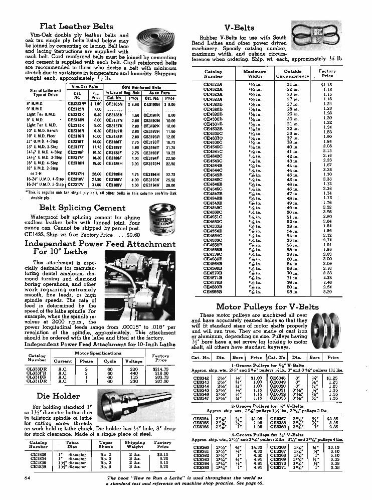
Flat Leather Belts Vim-Oak double ply leather belts and
oak tan single ply belts hated below may be joined by cementing or lacing. Belt lace and lacing instructions are supplied with each belt. Cord reinforced belts must be joineii by cementing and cement is supplied with each belt. Cord reinforced belts are recommended to those who desire a belt with minimum stretch due to variations in temperature and humidity. Shipping weight each, approximately ~ lb.
Vim-Oak Bella Cord Reinforced Bella Size of Lathe and
CaL Fae. In Lieu of Reg. Belt Aaan Extra Type of Drive No. Price ~ Price CaL No. Price
9' H.M.D. CE2323No $ 1.90 CE3185N $ 6.60 CE3110H $ 8.50 9' H.M.D. CE2312N 7.00 .... .. ... ...... .. ...... . . .... . light Ten H.M.D. CE2313K 8.50 CE3188K 1.50 CE3191K 8.00 9' U.M.D. . CE2315N 8.00 CE3187N 2.00 CE31I2N 10.00 light Ten U.M.D. CE2316K 8.00 CE3187K 2.00 CE31I2K 10.00 10' U.M.D. Bench CE2316R 9.50 CE3187R 2.00 CE3182R 11.50 10' U.M.D. Floor CE2316R 10.00 CE3188R 2.00 CE3193R 12.00 13' U.M.D. 4·Step CE2316T 14.00 CE3188T 2.75 CE31931" 16.75 13' U.M.D. 3·Slep CE2317T 17.75 CE3189T 4.00 CE31MT 21 .75 14)4' U.M.D. 4·Step CE2318F 16.50 CE3188F 2.75 CE3193F 19.25 14)4' U.M.D. 3·Step CE2317F 18.50 CE3189F 4.00 CE31MF 22.50 16' U.M.D. 4·Slep CE2316H 19.50 CE3188H 3.00 CE3183H 22.50 16' U.M.D. 3·Slep
or 2·H CE2317H 28.00 CE3189H 4.75 CE31MH 32.75 16·24' U.M.D. 4·Step CE2316V 21.50 CE3188V 4.00 CE3193V 25.50 16·24' U.M.D. 3·Slep CE2317V 31.00 CE3189V 5.00 CE3194V 36.00
° ThIS IS regular oa k Ian SIngle ply belt, .11 olher belts in this column are Vim·Oak double ply.
Belt Splicing Cem ent Waterproof belt splicing cement for gluing
endless leather belts with lapped joint. Four ounce can. Cannot be shipped by parcel post. CEI433. Ship. wi. 6 oz. Factory Price .... . $0.60
In dependent Power Feed Attachment F or 10" Lat h e This attachment is espe
cially desirable for manufacturing dental amalgum, diamond turning and diamond boring operations, and other work requiring extremely smooth, fine feeds, or high spindle speeds. The rate of feed is determined by the speed of the lathe spindle. For example, when the spindle revolves at 2400 r.p.m., the power longitudinal feeds range from .00015" to .01S" per revolution of the spindle, approximately. This attachment should be ordered with the lathe and fitted at the factory. Independent Power Feed Attachment for lO-Inch Lathe
Catalog Motor Specifications
Number Current Ph ...
CL333D R A.C. 3 CL333FR A.C. 3 CL33IBR A.C. I CL33lDR A.C. I
Die Holder For holding standard I "
or 1 yz' diameter button dies in tailstock spindle of lathe for cutting screw threads
Cycle
60 60 60 60
Factory Voltage P rice
220 $214.75 440 218.00 115 203.75 230 207.00
on work held in lathe chuck. Die holder' has ~" hole, 3" deep for stock clearance. Made of a single piece of steel.
Catalog Tak .. T a per Shipping F a ctory Number Die. Shank Weight P rice
CEI829 I " diameter No. 2 2 lb • . $5.10 CEI834 I" diameter No. 3 3 lb • . 5 .75 CEI838 1 ~. diameter No. 2 2 lb •. 5.10 CEI839 I ~" diameler No. 3 3 lb •. 5 .75
V-Belts Rubber V-Belts for use with South
Bend Lathes and other power driven machinery. Specify catalog number, ~ . maximum width, and outside circum-ference when ordering. Ship. wi. each, approximately ~ lb.
Catalog Maxiznum Outaid e Factory Number Width Circ:uftlference Price
CE452IA l~ in. 21 in. $1.15 CE4522A l~in. 22 in. 1.15 CE4523A l~ in. 23 in. 1.15 CE4527A l~ in . 27 in. 1.18 CE4527B l~ in. 27 in. 1.24 CE4S28B 1~l n. 28 in. 1.26 CE4529B 1~ln. 29 in. 1.28 CE4530B 1~ln. 30 in. 1.30
CE4S3IB l~ in. 31 in. 1.32
CE4532B l~in. 32 in. 1.34
CE4S35C 1!1o in. 35 in. 1.83
CE4537C 1!1o In. 37 in. 1.90 CE4538C 1!1o in . 38 in. 1.94 CE4540C 1!1o in. 4Oin. 2.08 CE454IC 1!1o in. 41 in. 2.13 CE4542C l~ iD . 42 In. 2.18 CE4543C 1!1o in. 43 in. 2.23 CE4544B l~ in. « in. 1.67 CE4544C 1!1o in. « In. 2.28 CE 4545B l~iD. 45 in. 1.70 CE4545C l ~ iD. 45 In . 2.33 CE4546B l~in. 46 In. 1.72 CE4546C 1!1o in. 46 in. 2.38 CE4547B l~ in. 47 in. 1.74 CE4S48B l~ in . 48iD. 1.75 CE4549B 1~ ln. 49 In. 1.76 CE4549C 1\{o in. 49 In. 2.52 CE4550C 1!1o in. SOin. 2.56 CE455IC 1!1o in. 51 in . 2.60 CE4552C 1\{o in. 52 in. 2.84 CE4553B I~ in. 53 in. 1.84 CE4554B 1l"U in. 54 In. 1.86 CE4554C 1\{o in. M in . 2.72 CE4555C 1\{o in. 55 in. 2.74 CE4558B l~ in . 56 in. 1.91 CE4558B l~ in. 58 in. 1.95 CE4559C 1\{o In. 59 in. 2.83 CE4560B 1~ln. 6O in. 2.00 CE4564B l~ in. 64 in. 2.09 CE4568B t~ in. 68 in . 2.18 CE4570B l~ in. 70 in. 2.23 CE4571B l~ in. 71 In. 2.28 CE4578B l~ iD. 78 in. 2.48 CE4580B l~ in. BOln. 2.54 CE4S88B l~ in. 98 in. 3.20
Motor P u lleys for V -Belts These motor pulleys are machined all over
and have accurately reamed holes so that they will fit standard sizes of motor shafts properly and will run true. They are made of cast iron or alu~um, depending on size. Pulleys having ~. bore have a set screw for locking to motor shaft, all others have standard keyways.
Cat. No. 1 Dia. I Borel Price lleat. No .1 Dia. Price
I-Groo .. Pullaya for 1!1.' V-Balta . Appro". ship. wb. 2~' and 2 1!.(,' pulley. ~ lb., 3' and 3'~" pullay. I~ Ibo.
CE8342 CE8343 CE8344 CE6345 CE8348 CE8347
CE83S4 CE8355 CE8356
2'Az" 2'Az" 2 !.(," 21~" 21~' 21~"
Appro" .hip wb .,
CE8360 21~" CE8361 21~' CE8362 21~' CE8363 2'~' CE8364 2'~' CE8365 2"",'
~" %" ~' ~" %" ~'
~" ~" I" ~' ~' I "
$1.00 CE8348 1.00 CE8348 1.00 CE8350 LIS CE83S1 LIS CE8352 LIS I CE63S3
$4.30 CE6366 4.30 CE8367 4.30 CE8368 4.95 CE8369 4.95 CE8370 4.95 CE8371
3" t.~' 3' %" 3" ~"
3'~" n: 3""'~ 3"",' ~"
3 '"," ~' 3 '"," ~" 3~" I " 3'!j4" ~' 3 ""," ~" 3""'~ I '
$1.25 1.25 1.25 1.35 1.35 1.35
$2.35 2.35 2.35
$5. 10 5. 10 5. 10 5.35 5.35 5.35
64 Tm. book "How to Run a Latm." bused throulhout tm. world as a standord te:ttt and refer .... u on machi_ shop practiu. See pale 65.

Special Micrometer Collars Graduated collars on South
Bend Lathes follow U.S. custom and are graduated in thousandths of an inch to measure the advance of the tool itself. Obviously, if the tool advances 1/ 1000 inch the work diameter is being reduced 2 / 1000 inch. European custom is to graduate the collar to read in thousandths the amount the work piece is being reduced. Such collars are known as DIRECT READING and can be supplied in lieu of standard collars at prices shown below.
LARGE DIAMETER easy reading graduated collars with regular graduations are regular equipment on 10' and larger lathes and can be supplied at extra cost for 9" and Light Ten Lathes as listed below.
METRIC graduated collars can be supplied for any South Bend Lathe if ordered with lathe, no extra cost.
Large Die . Reg. Grad. D irect Reading Size Lathe
Cat. No . Price Cat. No.
9" &: Liqht Ten CL2111NK $4 .15 CL25ZONK 10" .. ... .. .... CL25ZOR
13", 14 ~", 16", 16·24" , ... .. .... . CL2S20TH No. 2·H .... CLZ5ZOP
How to Run a Lathe A Practical Handbook
on Lathe Operation
"How to Run a Lathe" is a complete reference book and manual on the care and operation of the back-geared screw-cutting lathe. It is a practical handbook for the machinist, lathe operator, apprentice, or shop man. Clearly written in simple, non-technical language, the instruction material is easy for the beginner to understand. Printed in English, Spanish, anq Portuguese, languages.
Now in its 53 rd edition, this book has been improved and perfected by sugcjestions, criticisms, and ideas that have been submitted by hun-
Price
$2.95 3.50 4.25 4.50
dreds of practical shop men. The latest shop practices and methods used in modern industry are accurately described. Contains 128 pages 5Ys' x 7 Ys" and more than 3SO illustrations.
Partial List of Con ten ts History of the Lathe Machining Work Between Centers
Chuck Work ENctinll and Levellnllthe Lathe
O_Hon of Lathe ConlTols Tape, Turning and Boring Drilling, Reaming, and Tapping CuHing Screw Threads
Lathe Tools and Their Application
How to Take Accurate Measurement' Special 00"8' of Work
Catalog Number
CE3450 CE3451 CE3452 CE3454
" How to Run a Lathe", English (paper) ....... . "How to Run a Lathe" , English (leatherette) ... . "How to Run a Lathe", Spanish .............. . "How to Run a Lathe" , Porluque&e .. .... . . .
Price Postpaid
$0.50 1.50
.50
.50
Machinery's Handbook An engineering reference book for ma
chinists, students, designers, engineers, and executives. It is a practical guide for use in conjunction with engineering and vocational courses. Has 1911 pages, 1310 illustrations.
Cat. No. CE700. Machinery's Handbook. Price to.b. factory ... . .. .. ....... . .. $9 .00
Patented Desioii'
Tubular Steel Benches Designed especially for our 9" and Light Ten Bench Lathes
with horizontal motor drive, this sturdily constructed all steel . bench will give your lathe the rigid support it needs for the most satisfactory operation. Bench is 32" high, 32' wide and 51 72" long, large enough for lathes having beds up to 3 72' long. May also be used for many other purposes.
Heavy gauge sheet metal panels are securely welded into the tubular frame. A built-in chip pan with %" bead around the edge forms the top of the bench. This permits using a coolant if desired, and prevents chips from falling to the floor. Six drawers 1072" wide, IS" long, 5 72" deep (inside dimensionsl provide ample storage space for chucks, tools, lathe accessories, etc. Bench is nicely finished in gray wrinkle enamel.
CE1737. Tubular Steel Bench, 32" high, 32" wide, 51 72" long, for 9" and Light Ten Horizontal Motor Driven Bench Lathes with 3' or 3 )1' bed lengths. Ship. wt. 3361bs .. . $185.00
Angle Steel Bench With Wood Top Heavy angle steel construction, 29;(6" or 34* high, with
hardwood top 26" x SO" x I %;" thick. For 9" and Light Ten Horizontal Motor Driven Bench Lathes, any bed length. This also makes an ideal work bench for general shop use. Bench top is edge glued and has oil finish. Price does not include drawer, which is listed separately below.
Bench is shipped knocked down with all necessary bolts for assembling. Metal parts are finished with gray enamel. The sturdy construction of this bench makes it ideal for mounting a vise, surface plate, drill press, grinder, shaper, or other substantial equipment as well as the lathe.
CEI780. Steel Bench 29%;' high with wood top (less drawerl . Shipping weight, 84 Ibs. Factory Price .. .. ... $42.50
CE1849. Same as above but 34" high . ............ $44.50
Drawer for Bench CE1780D. ,Prawer for above bench, 20Ys' wide, 14' long,
3%;" deep. Shipping weight 9 Ibs. Factory Price . ..... $8.25
lncreose production with South Iknd double tool crou slides. See ~ge 41. 65

New South Bend Vertical Spindle ~ Milling. Machine
The new South Bend Vertical Spindle Precision Milling Machine is designed for maximum convenience and ease of operation. It is highly efficient for a wide variety of exacting toolroom and production work. Heavily constructed column with 3-point bearing on floor provides rigid support for the head and table assemblies. Massive knee has wide dovetail bearings and long, tapered gibs for both column and table.
The universal type head swivels full 360° for milling, drilling or boring at any angle. Worm gearing and precision graduations permit quick and easy adjustment of head angle. Rask and pinion ram adjustment provides IS' movement of keyed overarm for positioning head assembly.
Fairbanks Morse Axial Air-Gap Motor designed for operating in any position is mounted on milling machine head. Motor housing swivels around spindle for maximum flexibility in setting up work. A compound V-belt and timing belt "1o-Loss" drive transmits power to the spindle with extreme smoothness. Aluminum pulleys are accurately machined and balanced.
COMPARE THESE
FEATURES • Keyed overarm with 4Y2' diam ... ftangH ram ho.
tapered libs and permanently mounted rack and pinion adiultment for politioning head. This feature increases the cross milling copacity and allure, accurate movemen' '0' chang_ In set-up • .
• Eight spindle speed. with convenient belt te"lion ........ fa, quick and ealY speed chanles_
• tlL.4ols" drive to spindle at all .peed. tran,mits full h.p. through Iiml"9 bell.
• Head il .. mi· ..... caltlna honed to a petted preci.ion ft. to quill-360° rotation of head by worm and gear.
• Quill II Bround and precision fttted to bored and honed heaCl. Hal lever operated fall feed and handwh_1 operated Ilow feed . (Manual feed Ilandard. Automatic feed available at extra cost on deferred d ... livery basis.) Turnstile lever for rapid hand feed, d is. engage. when worm a,cd worm gear flne feed is used.
• Spindle hal dependable mlcrom_ depth slop graduated In thoulandthl, and polltlve quill lock.
• Spindle II m ..... of hardened and ground alloy lteeI, hal 1 ~. Ion-Ipllne drive, 10k .. No. 30 MM quick change individual holden.
• Spindle face has four %·.16 bolt holes for mounting face mills, efc.
• Large diameter easy reading graduated collors provided fa, polltlonlng lable.
• Lever locks for table, kn .. and saddle conveniently locoted on front of machine.
• Adjullable llopl in T -1101 provided fo, regulating lenglh of lable lrav".
• Manual longitudinal and cross-feeds to tabl. are standard equipment. Power longitudinal feeds available at extra cost on deferred delivery basis.
• Troughs and precision measuring bars with dial Indicator Itops are available at extra COlt on deferred d .. ivery baili.
EQUIPMENT Equipment included in price of millinq machine
consists of: three-phase A.C. motor; reversing switch; maater collet holder; wrench; and four collets having ~"'f ~~ %* and ~* capacities.
PRICES OF SOUTH BEND VERTICAL SPINDLE MILLING MACHINES WITH
3 ph .• 60 cy., 220/ 440 v., A.C. Moto ...
Catalog Table Motor Factory Number Length R .P .M . H .P . Price
MIL3212 32" 1200 ~ $1675 MIL3218 32" 1800 I 1675 MIL4212 42" 1200 ~ 1750 MIL4218 42' 1800 1 1750
Note : Write for price of milling ma.chine with single-pbase motor in lieu of 3-phal. motor.
Convenient belt tension release permits changing speeds quickly and easily. Eight spindle speeds are available. Reversing switch controls direction of spindle rotation, permitting right or left-hand milling.
Spindle is made of hardened and ground alloy steel and runs in precision bearings. The ten-spline 'spindle has 4" of travel with lever for rapid movement and handwheel for slow feed. A dependable micrometer depth stop is graduated in thousandths and positive quill lock is provided. Spindle has No. 30 milling machine taper and takes collets up to ~" capacity. Individual tool holders have up to I" capacity.
The table is 9" wide and is available in 32" or 42" length, providing 20' or 30' longitudinal travel respectively. Movement of table is controlled by 1 y.;:" - 5 thread Acme feed screws, each equipped with large easy-reading micrometer collars. Adjustable stops are provided for regulating the length of the table feed. Three T-slots for clamping work or fixtures extend full length of table. Table has dual controls for operating from either end.
66 All South Bend LothU. 10"-1' Coll~t and large,., take the !ame si"e collet_
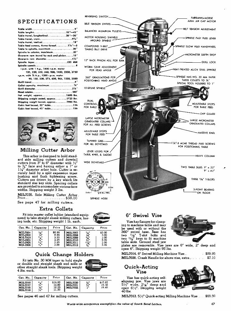
SPECIFICATIONS Table w idth •.• . • • . . .. . . . ... .•. . .... . ..•.••• 9 ' Tablelenllth • •... . . . . . . . • . . .. . . . . .••. 32 '_2 ' Tabl. travel, longitudinol . . . . .. . . .. . . . 20 "-30 · Table travel, cross • •..... .. •.. .. .•...• . . . . 9Y2 " Table travel, vertical • •• • •• . ••••• .• .•.• . . . • 1' · Tabl. feed screws, Acme thread • • •••• . • 1 Y4 "-5 Tabl. to spindle, maximum ••• • ••••. .. . .. . . 20 " Spindle to column, maximum ... . . ... . • . . .•. 20 " Overarm ram travel bV racle: and pinion • •• • • 15 /I
Ovefarm 'am diameter .. ... .. . .......... . 4Y2 " Spindle ta_ •. . •. ... . .. . . . . .. • . . . . . . #30 MM Spindle • peed • ••• • ••• • •••• • . . .• •• •. • • • .• • • •• •
"p.m . with 1 h.p ., 1100 r.p.m. motor 135, 220, 350, 560, 900, 1450, 2330, '3750
r.p .m . with ~ h.p., 1200 ,.p.m . motor 90, 150,230,375,600,965,1550,2500
Quill travel • . .. . .. . .•.•.•. • • •. ....•. . ....•. 4 · CoII.t capacity, maximum . . . . .. .• . • • . •••• . • Jj4"
Quill diam ..... .... .. . . . . . . . . .. .. . ... .... . 3Y. · Head rotate • • •• •••. . ..• . • . •.• . •..... .. . .• 360' Net welllht, ap .... ox . ••••• . . • • • . • •.•.• 1600 lb • . Shlpplnll w.illht crated, approx •• •• •••• 1725 lb • . Shipping w.ight baxed, approx .• • ••••• 1900 lb •. Cubic , ... baxed, 32 ' table • .• • • • . . •. .•. •. . "6 Cubic 'eet boxed, 42 ' lable • •••••...• • . • • •. 136
Milling Cutter Arbor This arbor is designed to hold stand
ard side milling cutters and dovetail cutters from 3" to 6' diameter with Ys' to U" face and having either a I " or 1 ~' diameter arbor hole. Cutter is securely held by a spht expansion taper bushing and flush tightening screw. Cutters are driven by a key which fits standard size key slots. Spacing collars are provided to accomodate various face widths. Shipping weight 3 Ibs.
WIDE OO'VElfAllS .... -
MIL7035. Side Milling Cutter Arbor . Price .............. . .. . . . . .. $38.00 SPINDLE NOSE
See page 47 for milling cutters.
Extra Collets Fit into master collet holder (standard equip
ment) to take straight shank milling cutters, boring tools, etc. Shipping weight 1 lb. each.
Cat. No. Capacity Price Cat. No. Capacity
MIL7001 ~. $8.95 MIL7007 ~" MIL7002 J.1i' 8.95 MIL7008 ~.
MIL7003 '10" 3 .25 MIL7009 '-fI' MIL7004 ~. 3.25 MIL7010 %' MIL7005 ~. 3.25 MIL70n I ~" MIL7006 %' 3.00 MIL7012 ~.
Quick Change Holders Fit into No. 30 MM taper to hold single
or double end straight shank end mills or other straight shank tools. Shipping weight 4lbs. each.
Cat. No. Capacity Price Cat . No. Capacity
MIL7016 ' .... $14.60 MIL7~ ~" MIL7017 Ys" 12.80 MIL7021 ~" MIL7018 ~: 12.25 MIL7022 I " MIL7019 11.70
See pages 46 and 47 for milling cutters.
P rice
$3.00 3.00 3.00 3.00 3.00 3.00
Price
$15.65 19.30 19.45
FAIRBANKS-MORSE AXIAL AIR GAP MOTOR
BELT TENSION ADJUSTMENT
r_--;)"INIJU: FAST FEED LEVER
SLOW FEED HANDWHEEL
MICROMETER DEPTH STOP
_----__ QUILL LOCK
_1.HT, TI ••• nn ALLOY STEEL SPINDLE
---------SPINC'LE HAS NO. 30 MM TAPER TAKES COLlETS TO ~ .
SPECIAL TOOL HOLDERS TO l '
~~MASSNF KNEE
f----I !4 · ·5 ACME THREAD FEED SCREWS FOR POSITIONING TABLE
----------~IEA'VY COLUMN
6" Swivel Vise Vise has flanges for clamp
ing to machine table and may be used with or without the 360° swivel base. Base has two I l1'6" T -slot bolts and two 1\.i6' keys to fit machine table slots. Ground steel jaw
TWO TABLE SIZES, 9" x 32'
9' " 4 2 '
THREE ' l-I.' T-SlOTS
3·POINT BEARING '----ON flOOR
plates are removable. Vise jaws are 6' wide, 2" deep and open 6". Shipping weight 95 lbs.
MIL7014. 6' Swivel Milling Machine Vise .. .. MIL7036. Crank Handle for above vise, extra •.
Quick-Acting Vise
Vise has quick-acting selfahgning jaw. Vise jaws are 5 7'2" wide , 2\.i6' deep and open 6 7'2". Shipping weight 4Olbs.
MIL7013. 57'2" Quick-acting Milling Machine Vise .
. .$89.95 .. .. $7.10
.$69.50
World-wide acceptance esemplifies the value of South BeruilAthes. 67
,

South Bend 7-inch ~ Bench Shaper The South Bend 7 ' Shaper has been developed to meet tool
room and ~dustrial demands for an accurate, compact bench shaper that is precision engineered and sturdily constructed. It has the built-in accuracy and versatility for rapid machining on small parts. The stroke rate per minute is higher than on larger shapers, permitting greater production on work within its capacity. The ease of setting up work in the bench shaper, its high operating speeds, and the low power consumption of the fractional h.p. motor, keep costs to a ·minimum. Built to the same high standards that have made South Bend Lathes famous for their precision and durability, this shaper is capable of the most exacting work on precision parts of all kinds.
Ram has long dovetail bearings which provide rigid support for the cutting tool, even in the ememe forward position. Gib adjustment is provided, and dovetail ways are fitted with felt wipers on both ends of column. Length of stroke is regulated by crank gear eccentric adjustment, and rocker arm is graduated to indicate length of stroke in inches. A large handwheel is provided for adjusting the ram which is locked in position by a conveniently located binding lever. The crank gear is precision made for quiet operation. Oil impregnated bearings are used for both the crank gear and the countershaft.
Pressure lubrication is provided by an automatic pump which circulates lubricating oil from a large reservoir in the base of the shaper to the ram dovetail, bull gear and pinion, pinion shaft and rocker arm shaft.
Tool head swivels to any angle, and has 3 Y2' diameter mounting wjth accurately cut graduations 0 to goo right and left. The tool slide screw has a clear cut graduated collar reading in thousandths of an inch. The clapper box swivels on the tool slide and may be adjusted for clearance, regardless of the tool slide angle. A tool slide lock is provided so that ememe accuracy and flatness can be maintained.
Table has holes and slots on top and on each side for clamping work. A V-groove is also provided on one side of the table. The cross-feed screw has a clear cut graduated collar reading in thousandths of an inch. The cross rail on which table slides is substantially constructed with large widely spaced bearing ways. Gib adjustment is provided for take-up. Provision is made for locking the vertical adjustment. For safety, the cross-feed screw is so constructed that the nut will run off the thread when it has traveled the maximum distance in either direction. An adjustable front end support shoe travels with the table and provides ememe rigidity for heavy cuts regardless of table position.
Vise swivels to any angle, with base graduated 0 to goo right and left, and can be mounted on the top or right side of the table. Vise jaw inserts are made of heat-treated steel.
Motor required is ~ or Y2 h.p., 1725 r.p.m., and is mounted on a cradle at the back of the shapero Power is transmitted by V-belts. A quick acting belt tension release is provided for easy shifting of the belt to change speeds. All V-belts and pulleys are enclosed in substantial metal guards. If shaper is ordered without motor, specify voltage, phase, and cycle of motor to be used so that correct wiring can be supplied.
CSlOO. South Bend 7 ' Precision Bench Shaper with vise, drive unit for % h.p . motor, motor pulley, V-belts, guards, work light, and built-in pushbutton type across-tha-line manual starter for motor, but without motor, steel stand, or tool holder. (See pages 70 and 71.) Shipping weight crated 330 lbs. Boxed weight 400 lbs., cubic feet boxed 12. · Price . .. . .. .... $551.00
CSlOOM. South Bend 7' Shaper, same as above but with metric graduations. Price f.o.b. factory . . . ........... $551.00 *Cubic feel bozed with steel stand 38.
Specifications of South Bend 7" Precision Shaper
Ram Table
Length of Ram Stroke . .... . ... . . . ..... . . . . ... . ..... 0 to 7 ' Strokes Per Minute, approximate ... . .. . . . . .. .42-75-120-195
Length of Top . . . . . .. . .... . ................ . ....... . 6~6' Width of Top ......... " . ..... .. ... . .. .... ..... . .. . .. . . 5 '
Cutting Speeds ... ... ... . .. . . . .. . .. 3 to 114 feet per minute Depth of Table . . ... .. . ... .. .... . .. . .. . ..... .. . . . . ... 5 %' T_IHead
Length of Vertical Feed . . ... .. . .. . . . .. . ........... . .... 3 ' Tool Post Takes Tool Holder Shank .. .. . . . .. ... . . . . %' x l~' Swivels . .... . ... . ....... .. .. . . .. .. .. .... . .. .. .... . . 360°
Horizontal Travel. . ..... .. .. . . .. . .. . . . ... . .. ... .. ... . 9 Y2' Vertical Travel. . .. ... . .... . .. ...... .. ..... . .......... . 5' Distance from Ram ............................. Y2' to SY2' Power Cross-Feeds (reversible) ..... . .... . . . . . 002' to .012' Width of Slots .. . ............. . ...... . .. . .......... . . Vt6'
Vise Holes for Clamp Bolts .......... ... . . .. . ......... . . .. .. %I' Width of Jaws ......... . . .. . .... . .. .. . . .. . . . . .. ... . . .. 4 ' Depth of Jaws. ' . .. . .... . . .. ... . . . .... .. . ....... ... ..... I ' Maximum Opening .. . . ... . ........... . . .. ..... . ... . ... 4 '
Motor Size Recommended . . .. . . .... .. ......... .. .. .. Va or Y2 h.p.
Rocker and crank with graduated eccentric adjustment for stroke
Tool head locks in any position. Guards ,on all belts and pulleys. Ouick-acting belt tension release Rugged clapper box also adjustable
61 A/our position CDrrioge $lop will save time and increase accuracy when spocing shoulders on shafts. See poge SO.

Close-up showing bearing on base for adjustable table support
FEATURES • Built-in work light pre
vents eye strain.
• Reversible power crossfeeds .002w to .012·.
• Built-in motor drive with quick acting belt tension release for changing speeds.
• Swivel vise graduated in degrees.
• Swivel tool head graduated in degrees.
• Convenient stroke adjustment 0 to r.
• Pressure lubrication to important bearings including ram dovetail.
NoIe: MoIor, tool holder, and ateel atand are nol included in requIar equipment of .haper.
Table support travels with table across bearing surface on base
Machining clutch teeth with aid of rotary indexing table
The only bench shope, with force feed lubrication to ram dovetail. 69
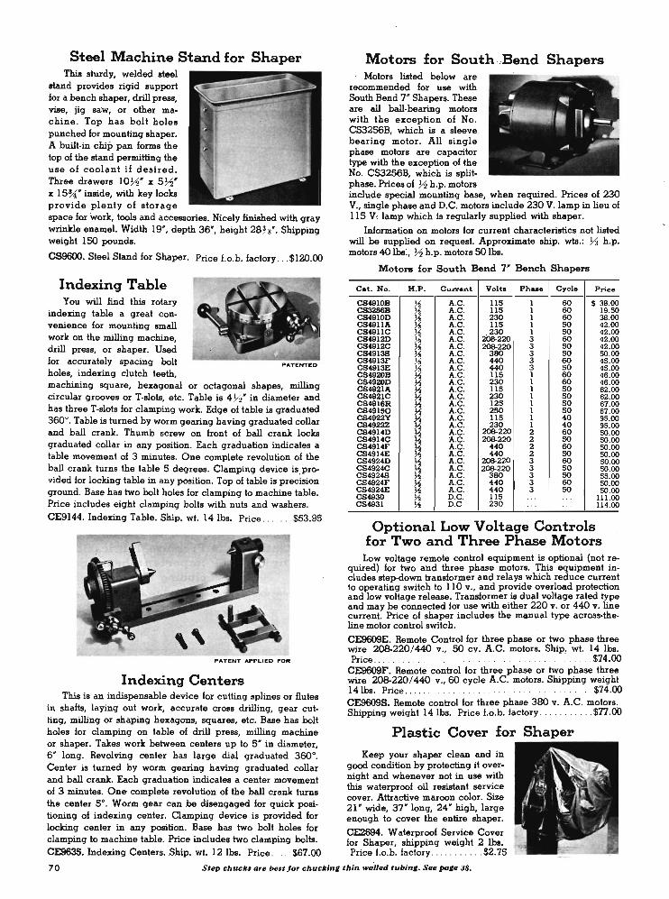
Steel Machine Stand for Shaper This sturdy, welded steel
stand provides rigid support for a bench shaper, drill press, vise, jig saw, or other machine. Top has bolt holes punched for .J:Ilounting shapero A built-in cliip pan forms the top of the stand permitting the use of coolant if desired. Three drawers 1072' x 5 72' x 15%;' inside, with key locks provid.!l plenty of storage space for work, tools and accessories. Nicely finished with gray wrinkle enamel. Width 19' , depth 36' , height 28%' . Shipping weight ISO pounds.
CS96OO. Steel Stand for Shapero Price f.o.b. factory ... $120.00
Indexing Table You will find this rotary
indexing table a great convenience for mounting small work on the milling machine, drill press, or shapero Used for accurately spacing bolt holes, indexing clutch leeth, machining square, hexagonal or octagonal shapes, milling circular grooves or T-slots, etc. Table is 4Yz' in diameter and has three T-slots for clamping work. Edge of table is graduated 360°. Table is turned by worm gearing having graduated collar and ball crank. Thumb screw on front of ball crank locks graduated collar in any position. Each graduation indicates a lable movement of 3 minutes. One complete revolution of the ball crank turns the table 5 degrees. Clamping device is provided for locking table in any position. Top of table is precision ground. Base has two bolt holes for clamping 10 machine table. Price includes eight clamping bolts with nuts and washers. CES144. Indexing Table. Ship. wt. 141bs. Price ..... . . $53.95
PATENT APPLIED FOR
Indexing Centers This is an indispensable device for cutting splines or flutes
in shafts, laying out work, accurate cross drilling, gear cutting, milling or shaping hexag.ons, squares, etc. Base has bolt holes for clamping on table of drill press, milling machine or shapero Takes work between centers up to 5 ' in diameter,
Motors for South .,Bend Shapers Motors listed below are
recommended for use with South Bend 7 ' Shapers. These are all ball-bearing motors with the exception of No. CS3256B, which is a sleeve . bearing motor. All single phase motors are capacitor type with the exception of the No. CS3256B, which is splitphase. Prices of Yz h.p. motors include special mounting base, when required. Prices of 230 V., single phase and D.C. motors include 230 V. lamp in lieu of 115 V, lamp which is regularly supplied with shapero
Information on motors for currenl characteristics nol listed will be supplied on request. Approximate ship. wis.: Y3 h.p. motors 40 Ibs:, Yz h.p. motors SO lbs.
Motol'll for South Bend 7' Bench Shapers
C.t. No. H .P. Current Volt. Ph ... Cycle Price ---------CS4910B J.i A.C. 115 1 60 $ 38.00 CS3256B J.i A.C. 115 1 60 19.50 CS4910D ~ A.C. 230 1 60 38.00 CS4911A A.C. 115 1 50 42.00 CS4911C J.i A.C. 230 1 50 42.00 CS4912D J.i A .. C. 208-220 3 60 42.00 CS4912C J.i A.C. 2()8.22O 3 50 42.00 CS4913S J.i A.C . 380 3 50 50.00 C84913F J.i A.C. «0 3 60 45.00 CS4913E J.i A.C. «0 3 50 45.00 C84920B J.2 A.C. 115 1 60 46.00 CS4920D J.2 A.C. 230 1 60 46.00 CS4921A J.2 A.C. 115 1 50 62.00 CS4921C J.2 A.C. 230 1 50 62.00 C84916R J.2 A.C. 125 1 50 67.00 C849150 J.2 A.C . 250 1 50 67.00 C84922Y J.2 A.C. 115 1 40 95.00 CS4922Z J.2 A.C. 230 1 40 95.00 C84914D J.2 A.C. 2()8.22O 2 60 50.00 CS4914C
~ A.C. 2()8.22O 2 50 50.00 CS4914F A.C . 440 2 60 50.00 C84914E J.2 A.C. 440 2 50 50.00 C84924D J.2 A.C. 2()8.22O 3 60 50.00 CS4924C J.2 A.C . 2()8.22O 3 50 50.00 C849248 J.2 A.C. 380 3 50 55.00 C84924F J.2 A.C. 440 3 60 50.00 C84924E J.2 A.C. 440 3 50 50.00 C84930 J.2 D.C. 115 . .. . .. 111.00 C84931 J.2 D.C 230 .. . .. 114.00
Optional Low Voltage Controls for Two and Three Phase Motors
Low voltage remole control equipmenl is optional (not required) for two and three phase motors. This equipment includes step-down transformer and relays which reduce current to operating switch 10 110 v., and provide overload prolection and low voltage release. Transformer is dual voltage rated type and may be connected for use with either 220 V. or 440 V. line current. Price of shaper includes the manual type across-theline motor control swilch.
CE9609E. Remote Control for three phase or two phase three wire 208-220/ 440 v., 50 cV. A.C. molors. Ship, wt. 141bs. Price . . . . . . $74.00
CE9609F. Remote control for three phase or two phase three wire 208-220/ 440 v.,60 cycle A.C. motors. Shipping weight 141bs. Price ..... .... . .......... . ...... . ... . ...... $74.00 CE9609S. Remote control for three phase 380 V . A.C. motors. Shipping weight 141bs. Price f.o.b. factory . . .... . ... . $77.00
Plastic Cover for Shaper
6" long. Revolving center has large dial graduated 360°. Keep your shaper clean and in Center is turned by worm gearing having graduated collar good condition by protecting it over-and ball crank. Each graduation indicates a center movement night and whenever not in use with
this waterproof oil resistant service of 3 minutes. One complete revolution of the ball crank turns cover. Attractive maroon color. Size the center 5°. Worm gear can be disengaged for quick posi- 21 ' wide, 37' long, 24' high, large tioning of indexing center. Clamping device is provided for enough to cover the entire shapero locking center in any position. Base has two bolt holes for CE2694. Waterproof Service Cover clamping to machine table. Price includes two clamping bolts. for Shaper, shipping weight 2 lbs. CE963S.lndexing Centers. Ship. wt. 121bs. Price .. .. . $67.00 Price t o.b. factory .. . . . . ..... $2.75
70 Step chuclu are best for chuckin, thin wailed tubin,. See pa,e lB.
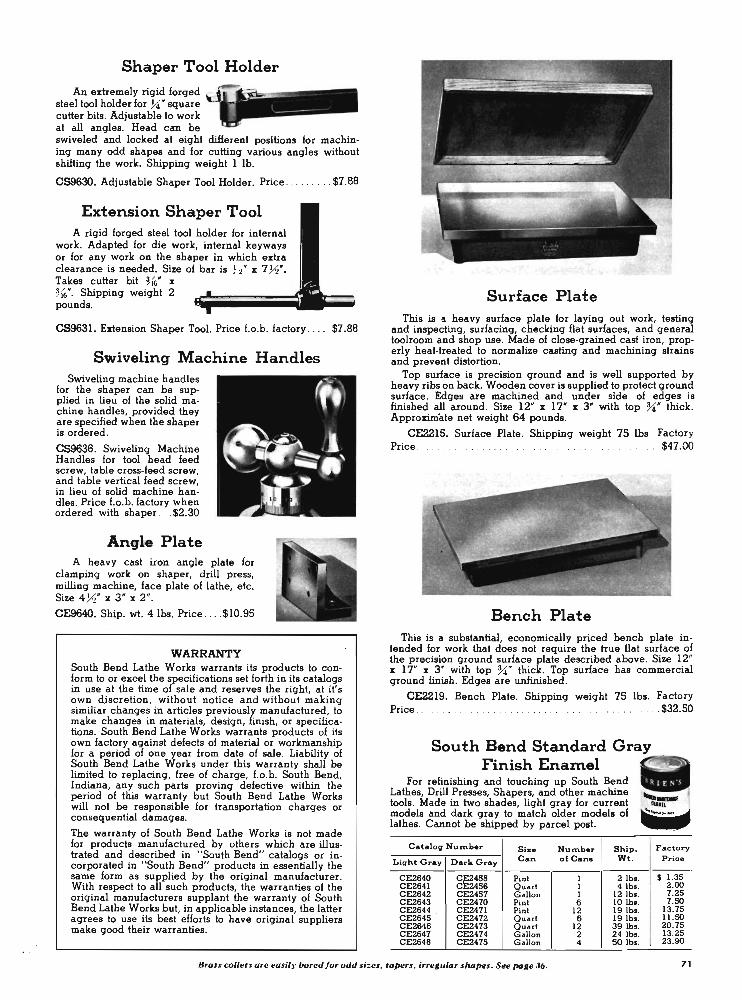
:.
Shaper Tool Holder
An extremely rigid forged steel tool holder for 7C square cutter bits. Adjustable to worle at all angles. Head cm be swiveled and locked at eight different positions for machining many odd shapes and for cutting various angles without shifting the worle. Shipping weight 1 lb.
CS963O. Adjustable Shaper Tool Holder. Price ..... . .. . $7.88
Extension Shaper Tool A rigid forged steel tool holder for internal
work. Adapted for die work, internal keyways or for any work on the shaper in which extra clearance is needed. Size of bar is ~ t· x 7 72". Takes cutter bit ~6" x ~{6"' Shipping weight 2 pounds.
CS9631. Extension Shaper Tool. Price f.o.b. factory . . .. $7.88
Swiveling Machine Handles Swiveling machine handles
for the shaper can be supplied in lieu of the solid machine handles, provided they are specified when the shaper is ordered.
CS9636. Swiveling Machine Handles for tool head feed screw, table cross-feed screw, and table vertical feed screw, in lieu of solid machine handles. Price I.o.b. factory when ordered with shaper ... $2.30
Angle Plate A heavy cast iron angle plate for
clamping work on shaper, drill press, milling machine, face plate of lathe, etc. Size 4 72" x 3 " x 2".
CE9640. Ship. wt. 41bs. Price . . .. $10.95
WARRANTY South Bend Lathe Works warrants its products to conform to or excel the specifications set forth in its catalogs in use at the time of sale and reserves the right, at it's own discretion, without notice and without making similiar changes in articles previously manufactured, to make changes in materials, design, finish, or specifications. South Bend Lathe Works warrants products of its own factory against defects of material or workmanship for a period of one year from date of sale. Liability of South Bend Lathe Works under this warranty shall be limited to replacing, free of charge, f.o .b. South Bend, Indiana, any such parts proving defective within the period of this warranty but South Bend Lathe Works will not be responsible for transportation charges or consequential damages.
The warranty of South Bend Lathe Works is not made for products manufactured by others which are illustrated and described in "South Bend" catalogs or incorporated in "South Bend" products in essentially the same form as supplied by the original manufacturer. With respect to all such products, the warranties of the original manufacturers supplant the warranty of South Bend Lathe Works but, in applicable instances, the latter agrees to use its best efforts to have original suppliers make good their warranties.
Surface Plat e This is a heavy surface plate for laying out work, testing
and inspecting, surfacing, checking flat surfaces, and general toolroom and shop use. Made of close-grained cast iron, properly heat-treated to normalize casting and machining strains and prevent distortion.
Top surface is precision ground and is well supported by heavy ribs on back. Wooden cover is supplied to protect ground surface. Edges are machined and under side of edges is finished all around. Size 12" x 17" x 3" with top 3i" thick. Approxim'ate net weight 64 pounds.
CE2215. Surface Plate. Shipping weight 75 Ibs Factory Price . . . . . . . $47.00
Ben ch Plate This is a substantial, economically priced bench plate in
tended for work that does not require the true flat surface of the precision ground surface plate described above. Size 12" x 17" x 3" with top %" thick. Top surface has commercial ground finish. Edges are unfinished.
CE2219. Bench Plate. Shipping weight 75 Ibs. Factory Price .. .. .. .. .. .. .. .. . . $32.50
South Bend Standard Gray Finish EnaInel
For refinishing and touching up South Bend Lathes, Drill Presses, Shapers, and other machine tools. Made in two shades, light gray for current models and dark gray to match older models of lathes. Cannot be shipped by parcel post.
CataJOII Nu",ber Size Number Ship.
Lillht Gray Dark Gr;1y Can of Cans Wt.
CE2640 CE2455 Pint I 2 lb •. CE2641 CE2456 Quart I 4 lb •. CE2642 CE2457 Gallon 1 12 lb •. CE2643 CE2470 Pint 6 \0 lb • . CE2644 . CE2471 Pint 12 19 lb • . CE2645 CE2472 Quart 6 19 lb •. CE2646 CE2473 Quart 12 39 lb •. CE2647 CE2474 Gallon 2 24 lb • . CE2648 CE2475 G allon 4 50 lb •.
.........,...
Factory Price
$ 1.35 2.00 7 .25 7 .50
13.75 11.50 20.75 13.25 23.90
Brass collets are easil)' bored for odd si:es. tapers, irregular shapes. See page 36. 71

South Bend Pedestal Grinder For Better-Faster-Easier Grinding
A great deal of careful research has gone into the design of the South Bend Pedestal Tool Grinder. To provide ample work clearance the grinding wheels are widely separated and the motor is mounted in the pedestal instead of between the wheels. Additional clearance for the worle is obtained by mounting the grinding wheel spindle toward the front of the pedestal. This construction also provides extra toe room for the operator. The U-shaped tool rests are adjustable to any angle and are also adjustable for wheel wear. The large water pot for cooling work is conveniently located and is removable for cleaning.
Large safety glass eye shields are hinged and are easily adjusted to three positions. Two light bulbs enclosed in the frame of each shield throw ample light directly onto the worle. Closefitting adjustable sparle guards built into the heavy wheel guards provide added protection. Wheel guards have removable end plates and large dust outlets for connecting with dust collector or exhaust ducts.
A pushbutton motor control is conveniently mounted at waist level on the front of the grinder frame. The motor is fully enclosed in the pedestal. A V-belt drives the grinding wheel spindle which revolves on sealed ball bearings. This construction practically eliminates vibration, removes the weight of the grinding wheels from the motor bearings and protects the motor from the abrasive dust of the grinding wheels.
The grinder is made with either S" grinding wheels or with 10' wheels. A ~ h.p. motor is required with S" wheels and a %' h.p. motor with 10" wheels. Any N.E.M.A. standard 3450 or 2S75 r.p.m. motor may be used. Equipment includes one coarse and one fine wheel for general worle; tool rests; wheel guards; eye shields with wiring, sockets, and 110 v. lamps; V·belt and pulleys; and built-in pushbutton type across-theline manual starter for motor. Price of grinder does not include motor. See page 73 for motors. If .9rinder is ordered without motor specify voltage, phase and cycle of motor to be used so correct wiring can be supplied.
CE2725. Pedestal Grinder with S" wheels and equip-ment as listed above, but without motor . . . ... . $257.
CE2726. Pedestal Grinder with 10" wheels and equipment as listed above. but withou t motor . ... . .. $260.
Knuckle Room To Spare
To give you plenty of room for both the worle and your hands, the motor is mounted inside the pedestal instead of between the grinding wheels. Spaced 12" apart, the peripheries of the 10" wheels extend 3 M" beyond the spindle housing between them.
SPECIFICATIONS
Wheel Size: For %' h.p. motor, 10" dia., IN face, U" hole. For >-2 h .p. motor, 8" dia. , IN face, %'" hole.
Spindle: Sealed hall hearings. Approximate speed 2450 r.p.m. Moto .. : Standard 2875 r .p .m . 50 cycle or 3450 r.p.m. 60 cycle and
D.C., ~ h.p. or % h.p. 0ve .. -a1l Dimensioll.l: 10"-49~" high, 20 %," wide, 22 %," deep.
S"- 49~' high, 20%,' wide, 20~' deep. Shipping Weight: 10" grinder 377 Ibs. crated for rail shipment,
437 Ibs. boxed for export. S"grinder 360 Ibs. crated for rail shipment, 420 Ibs. boxed for export.
Export Spce: 24 cuhic feet boxed.
72

Motors for Pedestal Grinders South Bend Pedestal Grinders require N.E.
Optional Controls for Pedestal Grinders
M.A. standard frame 3450 r.p .m. or 2875 r.p.m. motors as listed below. A Y2 h.p. motor is required for the grinder with 8 " wheels, and a % h.p. motor is required with 10' grinding wheels. Approximate shipping weight of Y2 h.p. motor is 40 lbs., %: h.p. motor 50 lbs. Write for information on motors for currents not listed.
r ..... \1 .. .... . :: - '''' .. .--Prices of South Bend
Pedestal Grinders include a push-button type acrossthe-line manual starting switch for the motor. Re mote control equipment is optional for two and three phase motors. This equipment includes step-down transformers and relays which reduce the current
i
. 72 h .p. Motors ~ h.p . Motors for 8 · Grinder for 10'" Grinder Curren t Cha racteristics to the operating switch to 110 volts, and provide
overload protection and low voltage release. Cat. No . Price Cat. No . Price Current V.olts
CE343lA $ 39.00 CE344lA $ 45.00 A .C . ll5 CE3431R 42 .00 CE3441 R SO.OO A.C. 125 CE3461B 39.00 CE3471B 45.00 A.C. ll5 CE3431C 39.00 CE3441 C 45 .00 A.C. 230 CE3461D 39.00 CE3471D 45.00 A.C. 230 CE3431Q 42.00 CE3441Q SO.OO A.C . 250 CE3463P 44.00 CE3443P 45.00 A.C. 208 CE3463C 44 .00 CE3443C 45 .00 A.C . 206-220 CE3463D 44.00 CE3443D 45 .00 A.C . 220 CE3433S 44 .00 CE3443S 50.00 A.C . 3BO CE3433E 39.00 CE3443E 45 .00 A .C . 440 CE3433F 39.00 CE3443F 45 .00 A .C. 440 CE3462D 44 .00 CE3442D 45 .00 A .C . 206-220 CE3462C 44 .00 CE3442C 45 .00 A.C . 206-220 CE3432F 39.00 CE3442F 45.00 A.C . 440 CE3432E 39.00 CE3442E 45.00 A.C . 440 CE3430K 65.00 CE3440K 120.00 D.C. ll5 CE3460L 67 .00 CE3470L 123.00 D.C. 230
Service Covers for Pedestal Grinders
This waterproof oil resistant service cover will protect your grinder from dust and dirt at night or whenever the grinder is not being used. Attractive maroon color, 12' wide, 28" long, 28" high.
CE2693. Waterproof Service Cover for Pedestal Grinder. Shipping weight 2 lbs. Factory Price . . . . . . . . . . . . . $1.95
Protect Your Drill Press With This Waterproof Service Cover
Use this durable waterproof oil resistant plastic service cover to protect your drill press overnight or whenever it is not in use. Effectively prevents dust and dirt from accumulating. Attractive maroon color with South Bend emblem printed in metallic ink. Size 12" wide, 28" long, 28" high, large enough for any South Bend single spindle drill press. Folds compactly to small package for easy storing when not in use. Use two or more on multiple spindle drill presses.
CE2693. Waterproof Service Cover for Drill Press, Ship. wI. 2 Ibs. Price .... .' . . $1.95
Phase Cycle ------ Shipping weight 23 Ibs.
1 1 1 1 1 1 3 3 3 3 3 3 2 2 2 2
50 50 60 Cat.
Volts Phase Cycle Factory
SO No . Price
---60 50 CE2636
208·220 2·3 SO $74.00
440 3·wire 60 SO 60 CE2637
208·220 2·3 60 74 .00
440 3 ·wire 50 50 60 CE2638 380 3 50 n.oo 60 ---50 60
CE2664 208·220 2
SO 74 .00 440 4·wire
SO ---... .. . CE2665
208·220 2 60 74 .00
440 4-wire
How to Get ProInpt Delivery You can get almost any South Bend product quickly,
either from stock carried by our distributors in all principal cities or direct from the factory at South Bend. No priority is required. To avoid delay, select the equipment you need and order immediately. Here are three ways to place your order:
1. See or telephone nearest distributor. Z. Order by mail from your distributor. 3. If no distributor is nearby, order di
rect from factory. See classified section of telephone directory for name
and address of South Bend Lathe distributor.
Tapping AttachInent for Drill Press
Jarvis Torqomatic Tapping Heads convert South Bend 14" Drill Presses into high speed, highly accurate tapping .machines. Automatic reverse speed is twice forward speed. Quill mounting and No . 2 Morse taper spindle types shipped complete ready for use.
CE9145. Tapping head No. 0 to No. 10 tap capacity with No. 2 Morse taper arbor.
'Shipping weight 61bs .. Price .. $70.00
CE9146. Tapping head No. 10 to Vt6" tap capacity with No. 2 Morse taper arbor. Ship. wI. 7 Y2 Ibs. Price ..... $85.00
CD9147. Tapping head No. 0 to No. 10 tap capacity, quill mounting. Shipping weight 6 Ibs. Price $70.00
CD9148. Tapping head No. 10 to Vt6" tap capacity, quill mounting. Ship. wt. 7 1'2 Ibs. Price .... $85.00
Carbide tipped cutter bits hJSt lotlger. See page 59 . 73
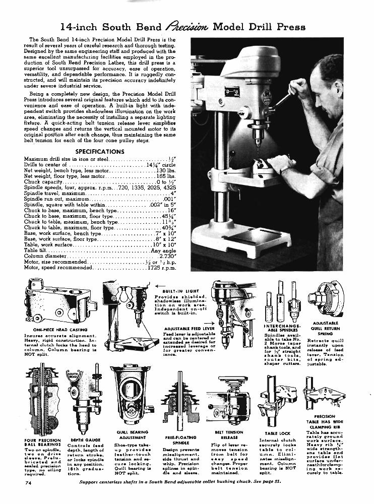
14-inch South Bend ~ Model Drill Press The South Bend 14-inch Precision Model Drill Press is the
result of several years of careful research and thorough testing. Designed by the same engineering staff and produced With the same excellent manufacturing facilities employed in the production of South Bend Precision Lathes, this drill press is a superior tool ·unsurpassed for accuracy, ease of operation, versatility, and dependable performance. It is ruggedly cbnstructed, and will maintain its precision accuracy indefinitely under severe industrial service.
Being a completely new design, the Precision Model Drill Press introduces several original features which add to its convenience and ease of operation. A . built-in light with independent switch provides shadowless illumination on the work area, eliminating the necessity of installing a separate lighting fixture. A quick-acting belt tension release lever simplifies speed changes and returns ~e vertical mounted motor to its original position after each change, thus maintaining the same belt tension for each of the four cone pulley steps.
SPECIFICA liONS Maximum drill size in iron or steel. .. . .... . ............. >-2' Drills to center of. .............. .. ..... .. . . ... 14 %" circle Net weight, bench type, less motor ..... .. ... . ...... 130 lha. Net weight, floor type, less motor ....... . . . .. . .. . ... 165 lha. Chuck capacity . ......... . ......... . ......... . . . . O to j1' Spindle speeds, four, approx. r.p.m ... 720, 1335, 202S, 432S Spindle travel, maximum ...... . ..... . ...... . ... . ..... . .4" Spindle run out, maximum ........ . .. . ........ . .... , .001 ' Spindle, square with table within ...... .... . ..... 002" in S' Chuck to base, maximum, bench type .. . .. .... . . .... " . 16' Chuck to base, maximum, floor type ......... .. . . . ... .4S%,' Chuck to table, maximum, bench type .. . . .. . .. . . . . . .. 11 Ys' Chuck to table, maximum, floor type .. .. . . . . .. .. .. .. .. 40%,' Base, work surface, bench type . . ... . .. . . . . ....... . 7 ' x 10' Base, work surface, floor type .. . . . . . . . ... .. . . .. . .. 8' x 12" Table, work surface .. . ... .. .. ...... .. .. . ....... . 10' l[ 10" Table tilt. .. .. .. .. . .. .. .. ... ...... . ........ . . .. Any angle Column diameter ... . ...... . .... . .. . ........ ...... 2.730' Motor, size recommended ..... . .. .. ..... . . .. .. Y:I or ) 2 h.p. Motor, speed recommended ............ . .. . .... 172S r.p.m.
IUILT-IN LIGHT Provide •• hielded, .hadowl ... illumination on work a .... . Independ.nt on-off • witch 18 built-in.
I neu .... accurat. alignment . Hea.y. rigid conatruction. Internal clutch locka the h.ad to column. Column b •• ring i. NOT .pUt.
ADJUSTABLE fEED LEVEl Feed le.,er 18 adju.table and can be centered or .. tended .. deaired for incr •••• d 1 ••• rage or for gr •• tel' conv.nience.
fOUl I'RECISION IALL IEAIINGS Two on apincll •• two on dri". .1 ••••. Prelubrie.ted and •• al.d preciaion type, no oiling required .
DlrTH GAUGE Control. fe.d depth, length of return stroke, or locka 8J>indle in any pomtion. 16th graduation • .
QUILL IEAIING ADJUSTMENT
Shoa-type talutup pro",id •• f.ather-touch tenaion and H
cur. locking. Quill bearing 18 NOT .pUt.
fIEE-fLOAnNG SI'INDLE
Deaign pre ... nUl .ni •• lignment. aide thru.t and whip. Preciaion splin .. in .pindle and .1_ ....
lEU TENSION IELEASE
nip of 1 .... re.no ••• tension fron> belt for ••• y ape.d chang ... Proper helt tension J'l'\aintained.
I NTEICHANGE-ABLE SI'INDLES
Spindl_ ••• ilable to take No. 2 Mor •• taper .hank toot.. and for M* atraiqht .hank tool., router bita, ahaper cutters.
TABLE LOCK
Internal clutch •• curely loc •• table to column. Eli:rninat .. .niaallgnment. Column bearing i. NOT split.
74 Support unterle$$ $1I4It$ in " South Bend "djwt"ble collet !nuhin, chuck. See po,e 51.
4]: ~
. -
. :;:-= (;." .
ADJUSTABLE QUIU IETUIN
SI'IING
R.tracts quill inatantly upon rel .... of feed le ... er. Tension of spring adju.table.
h· e.., -- - --
'" ~. I'REOSION
T AILE HAS WIDE CLAMI'ING III
Table haa accurat.ly ground work aurface .. H ••• ,. rib ~ .. wid. strengthen. t.bl. and provide. fl.t sur-face undern •• thforclalnpi ng work •• -curely to table.
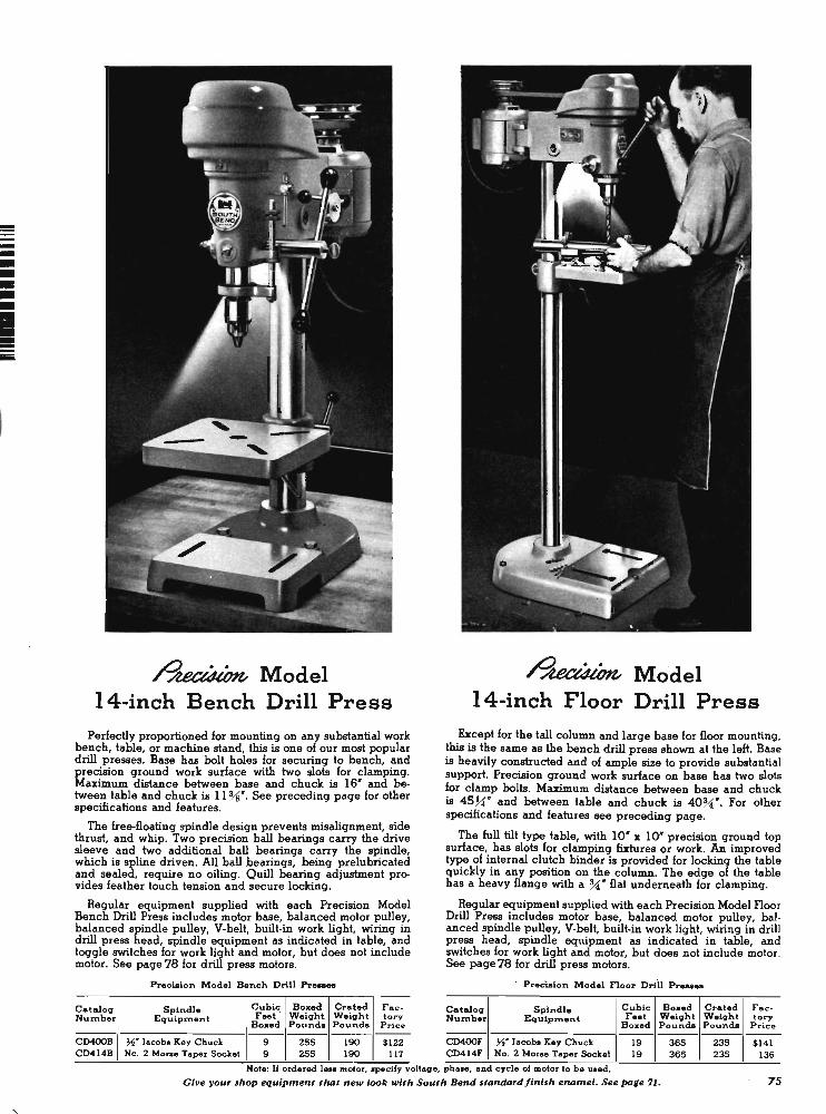
-----• ----ii
~Model 14-inch Bench Drill Press
Perfectly proportioned for mounting on any substantial work bench, table, or machine stand, this is one of our most popular drill presses. Base has bolt holes for securing to bench, and precision ground work surface with two slots for clamping. Maximum distance between base and chuck is IS" and between table and chuck is 11 %". See preceding page for other specifications and features.
The free-floating spindle design prevents misalignment, side thrust, and whip. Two precision ball bearings carry the drive sleeve and two additional ball , bearings carry the spindle, which is spline driven. All ball hearings, being prelubricated and sealed, require no oiling. Quill bearing adjustment provides feather touch tension and secure locking.
Regular equipment supplied with each Precision Model Bench Drill Press includes motor base, balanced motor pulley, balanced spindle pulley, V-belt, built-in work light, wiring in drill press head, spindle equipment as indicated in table, and toggle switches for work light and motor, but does not include motor. See page 78 for drill press motors.
Precision Mod.l Bench Drill Pr .....
Cataloq Spindle Cubic Box.d Crat.d Fae-Number Equipment Feet ' W.iqht W.iqht tory
Boxed Pound. Poundo Price ---------
CD400B ~. Jacob. Key Chuck 9 255 190 $122 CD414B No, 2 Morse raper Socket 9 255 190 117
~Model 14-inch Floor Drill Press
Except for the tall column and large base for floor mounting. this is the same as the bench drill press shown at the left. Base is heavily constructed and of ample size to provide substantial support. Precision ground work surface on base has two slots for clamp bolts. Maximum distance between base and chuck is 45~" and between table and chuck is 40%"". For other specifications and features see preceding page.
The full tilt type table, with 10" x 10" precision ground top surface, has slots for clamping fixtures or work. An improved type of internal clutch binder is provided for locking the table quickly in any position on the column. The edge of the table has a heavy flange with a %"" flat underneaih for clamping.
Regular equipment supplied with each Precision Model Floor Drill Press includes motor base, balanced motor pulley, bal· anced spindle pulley, V-belt, built-in work light, wiring in drill press head, spindle equipment as indicated in table, and switches for work light and motor, but does not include motor. See page 78 for drill pre'ss motors.
. Prec'iaion Mod.l noor Driil Pr .....
Cataloq Spindle Cubic Boxed Crat.d Fac -Number Equipment Feet W.iqht W.iqht tory
Bozed Pouncla Pound. Price ---------CD400F ~. Jacobs K.y Chuck 19 365 235 $141 CD414F No . 2 Morse raper Socket 19 365 235 136
Note: U ordered. le .. motor, ~ecify voltaqe, ph • •• , and cycle of motor to be uaed.
Give your shop equipment thot n ew look with South Bend standard/inish enamel. See page 11. 75
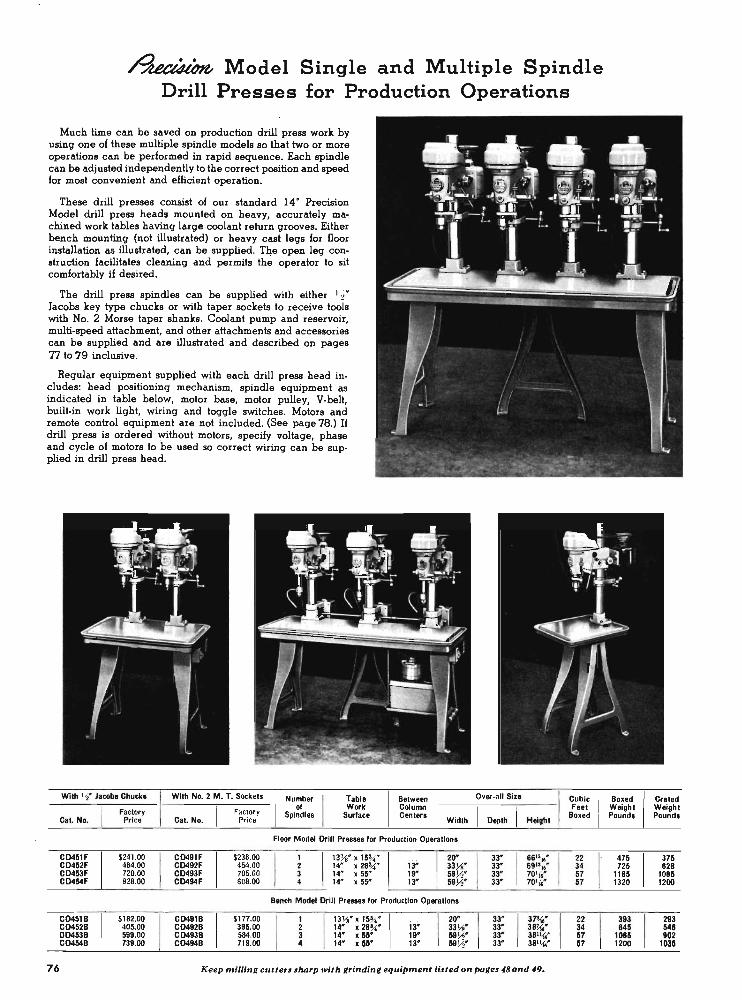
~ Model Single and Multiple Spindle Drill Presses for Production Operations
Much time can be saved on production drill press work by using one of these multiple spindle models so that two or more operations can be performed in rapid sequence. Each spindle can be adjusted independently to the correct position and speed for most convenient and efficient operation.
These drill presses consist of our standard 14" Precision Model drill press heads mounted on heavy, accurately machined work tables having large coolant return grooves. Either bench mounting (not illustrated) or heavy cast legs for floor installation as illustrated, can be supplied. T~e open leg construction facilitates cleaning and permits the operator to sit comfortably if desired.
The drill press spindles can be supplied with either '-'2" Jacobs key type chucks or with taper sockets to receive tools with No. 2 Morse taper shanks. Coolant pump and reservoir, multi-speed attachment, and other attachments and accessories can be supplied and are illustrated and described on pages T1 to 79 inclusive.
Regular equipment supplied with each drill press head includes: head positioning mechanism, spindle equipment as indicated in table below, motor base, motor pulley, V-belt, built·in work light, wiring and toggle switches. Motors and remote control equipment are not included. (See page 78.) U drill press is ordered without motors, specify voltage, phase and cycle of motors 10 be used so correct wiring can be sup· plied in drill press head.
With , ~. Jacob. Chuck. With No.2 M. T. Sockets
I Number
I Tabte
Factory Factory of Work
Cal. No. Pri ce Cat. No. Price Spindle. Surface I
Between Column Center.
Width
Floor Model Drill Pr ..... for Production Opera tion.
C0451F $241.00 C0491F $236.00
I 13~" x 15~N
I ia" 20"
C0452F 464.00 C0492F 454.00 14" x 28~'" 33JiN C0453F 720.00 C0493F 705.00 14N x5S" 19" 59Y:;N C0454F 828.00 C0494F 808.00 14N . x 5S" 13" 59Y:;N
Bench Modet Drill Pre ..... for Production Operation.
C0451B $182.00 C0491B SI77.00
I 13VoN x 15~'
I ;aw
I 20"
C0452B 405.00 CD492B 395.00 14" x 28!4N 33W OO453B 599.00 C0493B 584.00 14" x5S" IS" 59W C0454B 739.00 C0494B 719.00 14" xSS" 13" 59),<1"
Over-all SilO
I Oepth I Height
33" 68u1&"
33" 691116"
33" 70' , .. 33" 70116*
33"
I 37'~N
33" 38}{.N 33" 3B '~' 33" 3B"~"
76 Keep milling cutters sharp with grinding equipment listed on pages 48 and 49.
I Cubic Feet
Boxed
22 34 57 57
22 34 57 57 .
Boxed Crated Weight Weight Pound. Pound.
475 375 725 828
1185 1085 1320 1200
393 293 845 548
1085 902 1200 1035

I
Multi-Speed Attachment The Multi-Speed Attach
ment for South Bend 14" Precision Model Drill Presses provides twelve spindle speeds 380, 605, 650, 1040, 1040, 1120, 2870, 3025, 3Q70, 4900, 5170, and BOlO r.p.m. when used with 1725 r .p.m. motor. The attachment consists of an eccentric spindle, which is mounted in the drill press column to support a 4-step au:riliary cone pulley with two V-belts.
This attachment cannot be used with split phase motor No. CE3256B. Price includes eccentric spindle, 4-step cone pulley and two V-belts. Shipping weight 8 Ibs.
CD9135A. For ~ h .p . motor. Factory Price ...... . . .. ... . ... $IS.25 CD9~3SB. For ~ h .p . motor. Factory Price . . ....... .. . .. . . $IS.25
Note: Thia attachment cannot be ul ed with Head PQ8itioninq Attachment.
Belt Guard This belt guard provides
complete enclosure for V-belt. Guard is hinged and may be raised for changing spindle speeds. May be used with or without Multi-Speed Attachment.
- - ----~J ~. ~ ~~-It..... . ! ._ .. d ,;
CD913S. Belt G uard for use wi th Precision Model Drill Pre •• only. Shippinq weiqht lSlbs. Factory Price ..... . .. .. .. . . .. . .......... $13.50
Swivel Machine Vise For holding work on drill press table, milling machine,
shaper, etc. Swivel is graduated 1800 to permit setting vise at any angle with slots in table. Jaws are hardened and are replaceable. Jaws are 4 ' wide and I " deep. Maximum jaw opening is 4".
CE9100 Swivel Drill Press Vise. Shipping weight 18 pounds. Factory price . . . . . . . . . . . . . ....... . $26.00
Extra Spindles for Drill Presses
Extra spindles are interchangeable with regular drill press spindles supplied with either the Single or Multiple Spindle Precision Model Drill Presses.
CD912S. Spindle with No. 2 Morse taper hole for holdinq taper .hank tools. Drift included. Shippinq weiqht 3 lb • . Factory Price .... . .. . . .. $S.85
CD9126. Utility spindle with ~" " 1 %" deep otraiqhl hole for holdinq routinq tool., elc. Shippinq weiqhl 3 lb •. Factory Price ...... . .... . . $5.00
CD9127. Spindle With short laper for Yo' Drill Chuck No. CE1201. (Jacob. No. 34). Shippinq weiqht 2 lbs. Factory Price . . , ............ $4.20
CD9128. Spindle wilh No. 3 Mon e laper hole for holdinq taper .hank lools. Drift included. Shippinq weiqht 5 lb •. Factory Price .... .. . . . . $10 .50
Chuck and Arbor for Drill Press This drill chuck and arbor
are recommended for use with drill presses having spindles with No.2 Morse taper.
CEl201. Jacobo 3-jaw smooth body d rill chuck, 0 10 ~. capacity with pUllon key. Shippinq weiqht 2 ~ pounds. Factory Price ... . .. .. ..... $8.5S
CE9110. No. 2 Mone taper . hank arbor with tanq, for fittinq above chuck to drill p re .. spindle No. CD912S. Ship. wi. ~ lb. Factory Price $1.20
Universal Table Both upper and lower
slides have graduated swivels and may be turned through full 3600 Slides can be used without graduated swivels to reduce height if desired. They can be positioned at any angle with each other and may be turned individually or together. Each slide has feed screw with micrometer collar reading in thousandths of an inch. Dovetails are equipped with full length qibs for take-up. The precision ground work surface is 4" x 8 Ys* and maximum travel is 4" for either slide. Table has four slots for clamping work. Clamp bolts fit snugly into round slots in such a way that there is little danger of breaking out or otherwise damaging the slots. Supplied with base for use on drill press, milling machines, etc., also with a specially designed base for mounting on the South Bend 7" Shapero Slides and bases may be purchased separately if desired.
CE9156. Universal Table complete with base for South Bend Drill Press or other machine tools, two slides, two graduated swivels, and eight clamp bolts with nuts. Ship. weight 43 Ibs. Factory Price ... ......... . ........ $101.95
CE9150. Universal Table complete with base for South Bend 7* Shaper, two slides, two graduated swivels, and eight clamp bolts with nuts. Ship. wt. 37 lbs. Factory Price .. ... . . $102.95
CE9157. Single Table with one graduated swivel and four clamp bolts with nuts. Ship. wt. 191bs. Factory Price ... . $48.50
CE9158. Base only for adapting single table to South Bend 7 * Shapero Ship. wt. 3 Ibs. Factory Price . . . . .... . .. $4.00
CE9159. Base only for adapting single table to South Bend Drill Press or other machine tool. Ship. wt. 8lbs. Price .... $4.40
Wood Top Machine Stand This is a heavily construct:
ed angle steel stand 29%* high for mounting the bench shaper, drill press, or for other small machines.The glued wood top is 20* x 32" and is 1%* thick. Steel parts are finished in gray enamel. Shipping weight 52 lbs.
CE9141. Wood Top Machine Stand (less drawer) . .
Factory Price ......... $24.95 .
Dra.wer for Machine Stand Handy for keeping small tools, wrenches, etc. Finished to
match stand CE9141. Drawer is 20Ys" wide, 14" long, 3~6' deep. Price includes metal pull and wood slides. Shipping weight 9 lbs.
CE1780D_ Drawer for use with Machine Stand. Price $8.25
For precision lacing operations, )IOU need a micrometer carriage stop. See page 50 77
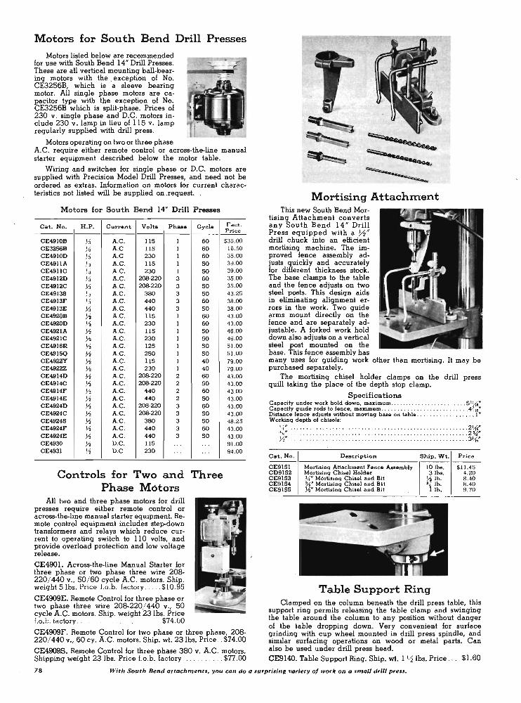
Motors for South Bend Drill Presses
Motors listed below are recommended for use with South Bend 14" Drill Presses. These are all vertical mounting ball-bearing motors with the . exception of No. CE3256B, which is a sleeve bearing motor. All single phase motors are capacitor type with the exception of No. CE3256B which is split-phase. Prices of 230 v. single phase and D.C. motors include 230 v . lamp in lieu of 115 v. lamp regularly supplied with drill press.
Motors operating on two or three phase A.C. require either remote control or across-the-line manual starter equipment described below the motor table.
Wiring and switches for single phase or D.C. motors are supplied with Precision Model Drill Presses, and need not be ordered as extras. Information on motors for current characteristics not listed will be supplied on _request. .
Motors for South Bend 14" Drill Presses
Cat. No. H .P . Current Volts Ph ... Cycle ------
CE4910B Va A.C . 115 I 60 CE3256B Va A.C . 115 I 60 CE4910D V. A.C . 230 1 60 CE4911A V. A.C. 115 I 50 CE4911C 1 / , 3 A.C . 230 1 50 CE4912D V. A.C . 208-220 3 60 CE4912C V. A.C . 208-220 3 50 CE4913S 73 A.C . 380 3 50 CE4913F % A.C . 440 3 60 CE4913E V. A.C . 440 3 50 CE4920B Va A.C . 115 I 60 CE4920D Yo A.C. 230 1 60 CE492lA Va A.C . 115 I 50 CE492lC Va A.C . 230 I 50 CE4916R Yo A.C. 125 I 50 CE4915Q Yo A.C . 250 I 50 CE4922Y Va A.C. llS 1 40 CE4922Z Va A.C . 230 I 40 CE4914D Yo A.C . 208-220 2 60 CE4914C Va A.C . 208-220 2 50 CE4914F Yo A.C . 440 2 60 CE4914E Yo A.C . 440 2 50 CE4924D Yo A.C . 208-220 3 60 CE4924C Va A.C. 208-220 3 50 CE4924S Va A.C . 380 3 50 CE4924F Yo A.C . 440 3 60 CE4924E Va A.C. 440 3 50 CE4930 Va D.C. 115 .. . .. . CE4931 Va D.C. 230 ... ..
Controls for Two and Three Phase Motors
All two and three phase motors for drill presses require either remote control or across-the-line manual starter equipment. Remote control equipment includes step-down transformers and relays which reduce current to operating switch to 110 volts, and provide overload protection and low voltage release.
CE490L Across-the-line Manual Starter for three phase or two phase three wire 208-220/ 440 v., 50/ 60 cycle A.C. motors. Ship. weight Sibs. Price f.o.b. factory . .... $10.95
CE4909E_ Remote Control for three phase or two phase three wire 208-220/ 440 v., 50 cycle A.C. motors. Ship. weight 231bs. Price Lo.b. factory . . . . . . $74.UO
Fact . Price
$35.00 IS.50 35.00 39.00 39.00 35.00 35.00 43.25 38.00 38.00 43.00 43.00 4S.00 4S.00 5 1.00 51.00 79.00 79.00 43.00 43.00 43.00 43. 00 43.00 43.00 48.25 43.00 43. 00 91.00 94.00
Mortising ' A ttachm:ent .. This new South Bend Mor
tising Attachment converts any South Bend 14" Drill Press equipped with a ~H drill chuck into an efficient mortising machine. The improved fence assembly adjusts quickly and accurately for different thickness stock. The base clamps to the table and the fence adjusts on two steel posts. This design aids in eliminating alignment errors in the work. Two guide arms mount directly on the fence and are separately adjustable. A forked work hold down also adjusts on a vertical steel post mounted on the base. This fence assembly has many uses for guiding work other than mortising. It may be purchased separately.
The mortising chisel holder clamps on the drill press quill taking the place of the depth stop clamp.
. Specifications Capacity under work: hold down, maximum ..... . .. . . . ........ . . ... 5 1U6'" Capacity guide rods to fence, maximum .. . . .. . . ..... . ... . ... ... . . .4'V&&" Distance fence adjusts without moving base on table . ... .... . ......... 1" Working depth of chisels:
~: : ::::::::: : ::::: : :: :::: :::::::: ::::::: ::::::: :::::::::: : ~~: Cat. No . Description Ship. Wt. Price
CE9151 Mortising Attachment Fence Assembly 10 lb •. $1l.45 CD9152 MortiSing Chisel Holder 3lbs. 4.20 CE9153 ~. MortiSing Chisel and Bit Va lb. 8.40 CE9lS4 %" Mortising Chisel and Bit ~ lb. 8.40 CE915S Va" Mortising Chisel and Bit lib. 9.70
Table Support Ring Clamped on the column beneath the drill press table, this
support ring permits releasing the table clamp and swinging the table around the column to any position without danger of the table dropping down. Very convenient for surface
CE4909F. Remote Control for two phase or three phase, 208- grinding with cup wheel mounted in drill press spindle, and 220/ 440 v., 60 cy. A.C. motors. Ship. wt. 231bs. Price .. $74.00 similar surfacing operations on wood or metal parts. Can CE4909S. Remote Control for three phase 380 v. A.C. motors. also be used under drill press head. Shipping weight 23 Ibs. Price I.o.b. factory. . . . . .. $77.00 CE9140. Table Support Ring. Ship. wt. 1 Y2 lbs. Price . .. . $1.60
78 With South Bend attachment" you con do a surpri,ing variety of work on a small drill press.
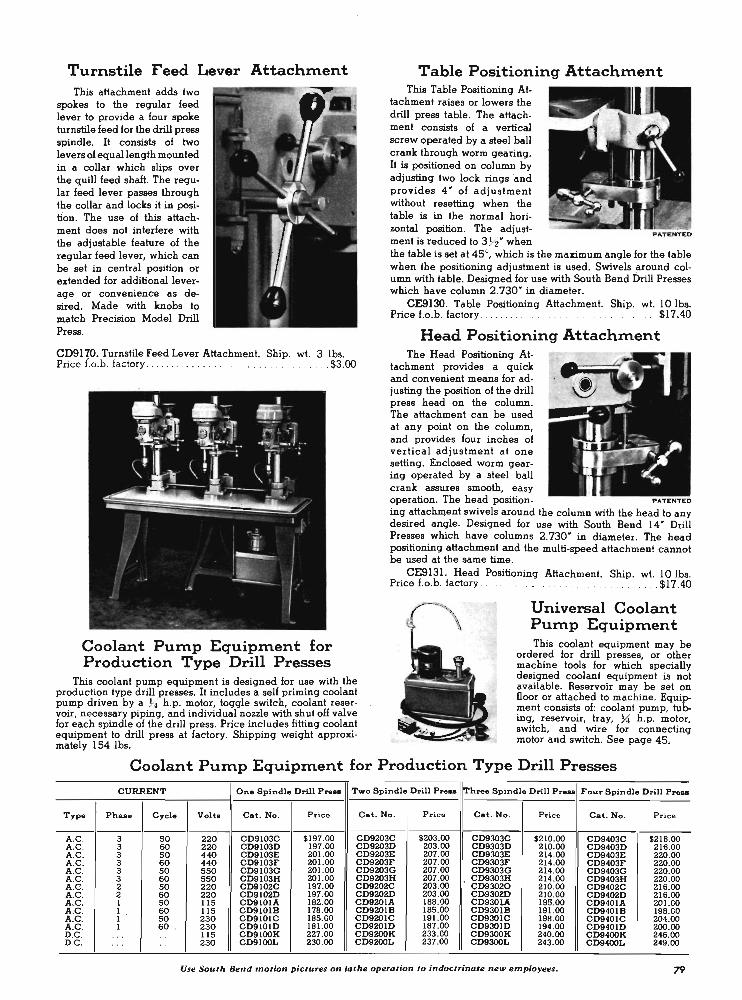
Turnstile Feed Lever Attachment This attachment adds two
spokes to the regular feed lever to provide a four spoke turnstile feed for the cIrill press spindle. It consists of two levers of equal length mounted in a collar which slips over the quill feed shaft. The regular feed lever passes through the collar and locks it in position. The use of this attachment does not interfere with the adjustable feature of the regular feed lever, which can be set in central position or extended for additional leverage or convenience as desired. Made with knobs to match Precision Model Drill Press.
Table Positioning Attachment This Table Positioning At
tachment raises or lowers the drill press table. The attachment consists of a vertical screw operated by a steel ball crank through worm gearing. It is positioned on column by adjusting two lock rings 'and provides 4 " of adjustment without resetting when the table is in the normal horizontal position. The adjustment is reduced to 3 72" when
PATENTED
the table is set at 45°, which is the maximum angle for the table when the positioning adjustment is used. Swivels around column with table. Designed for use with South Bend Drill Presses which have column 2.730" in diameter.
CE9130. Table Positioning Attachment. Ship. wt. 10 Ibs. Price f.o.b. factory . . . . . . .. ........ . . .$17.40
Head Positioning Attachment CD9170. Turnstile Feed Lever Attachment. Ship. wt. 3 Ibs. Price f.o.b. factory. . . . . . . . . . . . . . . . . . . . . . . . . . . .... $3.00
The Head Positioning Attachment provides a quick and convenient means for adjusting the position of the drill press head on the column. The attachment can be used at any point on the column, and provides four inches of vertical adjustment at one setting. Enclosed worm gearing operated by a steel ball crank assures smooth, easy
Coolant Pump Equipment for Production Type Drill Presses
operation. The head position- PATENTED
ing attachment swivels around the column with the head to any desired angle. Designed for use with South Bend 14" Drill Presses which have columns 2.730" in diameter. The head positioning attachment and the multi-speed attachment cannot be used at the same time.
CE9131. Head Positioning Attachment. Ship. wt. 10 Ibs. Price f.o.b. factory . . , .. ... .... ..... ' .$17.40
Universal Coolant Pump Equipment This coolant equipment may be
This coolant pump equipment is designed for use with the production type drill presses. It includes a self priming coolant pump driven by a %' h.p.· motor, toggle switch, coolant reser· voir, necessary piping, and individual nozzle with shut off valve for each spindle of the drill press. Price includes fitting coolant equipment to drill press at factory. Shipping weight approxi· mately 154 Ibs.
ordered for drill presses, or other machine tools for which specially designed coolant equipment is not available. Reservoir may be set on floor or attached to machine. Equipment consists of: coolant pump, tubing, reservoir, tray, %' h.p. motor, switch, and wire for connecting motor and switch. See page 45.
Coolant Pump Equipment for Production Type Drill Presses
CURRENT One Spindle Drill Pre .. ,Two Spindle Drill Pre .. Three Spindle Drill Pre .. Four Spindle Drill Press
Type Pha •• Cycle Volt. Cat. No . Price Cat. No. Price Cat. No . Price Cat. No . Price
A.C. 3 SO 220 CD9103C $197.00 CD9203C $203.00 CD9303C $210.00 CD9403C $216.00 A.C . 3 60 220 CD9103D 197.00 CD9203D 203 .00 CD9303D 210.00 CD9403D 216.00 A.C . 3 SO 440 CD9103E 201.00 CD9203E 207.00 CD9303E 214.00 CD9403E 220 .00 A.C . 3 60 440 CD9103F 201.00 CD9203F 207.00 CD9303F 214 .00 CD9403F 220.00 A.C . 3 SO 550 CD9103G 201.00 CD9203G 207 .00 CD9303G 214.00 CD9403G 220.00 A.C . 3 60 550 CD9103H 201.00 CD9203H 207 .00 CD9303H 214.00 CD9403H 220.00 A.C . 2 SO 220 CD9102C 197.00 CD9202C 203.00 CD93020 210.00 CD9402C 216.00 A.C . 2 60 220 CD9102D 197.00 CD9202D 203 .00 CD930W 210.00 CD9402D 216.00 A.C . I SO 115 CD9101A 182.00 CD920IA 188.00 CD930lA 195.00 CD9401A 201.00 A.C . I 60 115 CD9101B 178.00 CD920IB 185.00 CD9301B 191.00 CD9401B 198.00 A.C . 1 SO 230 CD9101C 185.00 CD920JC 191.00 CD930IC 198.00 CD9401C 204.00 A.C . I 60 230 CD910JD 181.00 CD9201D 187.00 CD9301D 194.00 CD9401D 200.00 D.C. ... . . 115 CD9100K 227.00 CD9200K 233 .00 CD9300K 240.00 CD9400K 246.00 D.C . . .. . . 230 CD9100L 230 .00 CD9200L 237.00 CD9300L 243.00 CD9400L 249.00
Use South Bend motion pictures on lathe operation to indoctrinate new employees. 79
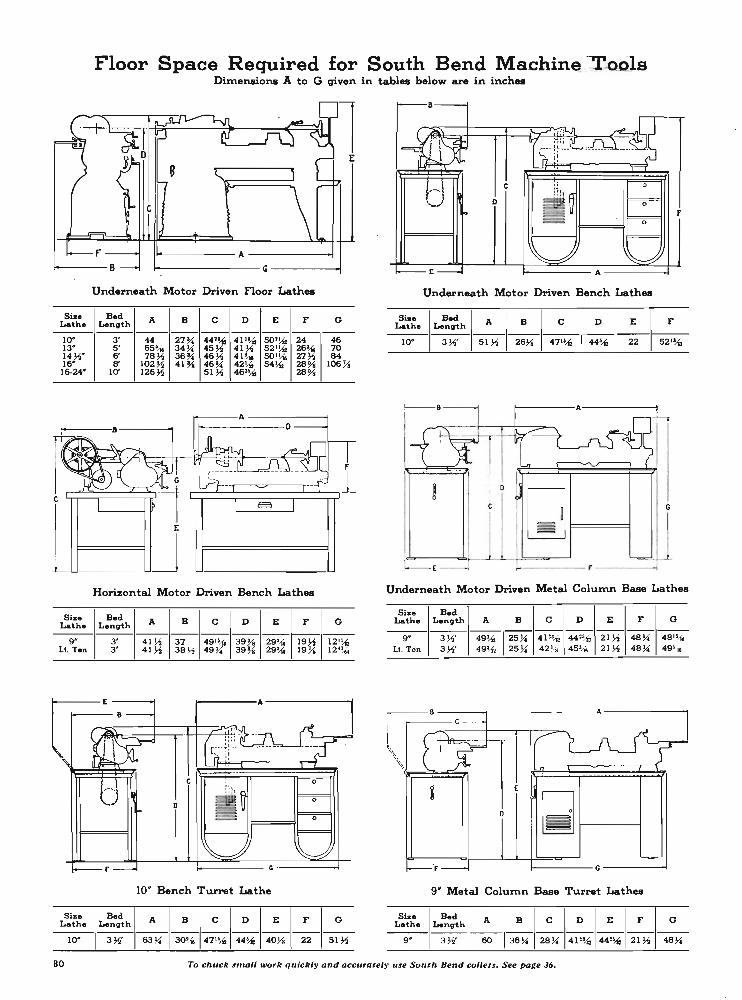
Floor Space Required for South Bend Machin~ ~-OQls Dimensions A to G given in tables below are in inches
Underneath Motor Driven floor Lathes
Siz. Bed A B C D E F G Lath. Length ----------------------
10" 3' 44 27 ~ 44'~ 41'~ 50'~ 24 46 13- 5' 65~ 34~ 45 ~ 41 ~ 52'~ 26~ 70 14~- 6' 78~ 36 ~ 46~ 41 '", 501~ 27~ 84 16- 8' 102 ~ 41 l-i 46 ~ 42~ 54~ 28 % 106 % 16-24- 10' 126~ 51 ~ 46"'{' 28 %
1--w ____ __ W __ -L _ _ W __________ _
Horizontal Motor Driven Bench Lathes
Size B.d A B C D E F G Lathe Length -------------~ -------
9" 3' 41 ~ 37 49"", 39 l-i 29% 19~ 12'~ LI. ren 3' 41 ~ 38 ~ 49 ~ 39 l-i 29% 19% 12"~'"
10' Bench Turret Lathe
Size Bed A B C D E F G Lathe Length ----------------
10- 3 ~' 63 ~ 30% 47'~ 44~ 40~ 22 51 ~
Underneath Motor Driven Bench Lathes
Sia. Bed A B C I D ElF Lath. Length
10" 3W 51 ~ 26Ys 47"'{' 44~ 22 52"~
~----A-----~
I
I GJF=====l G
,;c6----....... t---.lLJL--1--!==~--' '-- E~
Underneath Motor Driven Metal Column Base Lathes
Size Bed Lethe Length A B C D E F G
----------------------go 3 ~' 49~ 25 ~ 41'~ 44'~ 21 ~ 48 ~ 481~
Lt. ren 3 ~' 49'.-{, 25~ 42Ys 45% 21 ~ 48 ~ ·49~ 16
o
~----G----~
9' Metal Column Base Turret Lathes
Size B.d A B C D E F G Lath. Length ----------------------
9- 3 W 60 36 ~ 28 ~ 41'~ 44'~ 21~ 48 ~
80 To chuck small work quickly and accurately use South Bend collets_ See page 36.
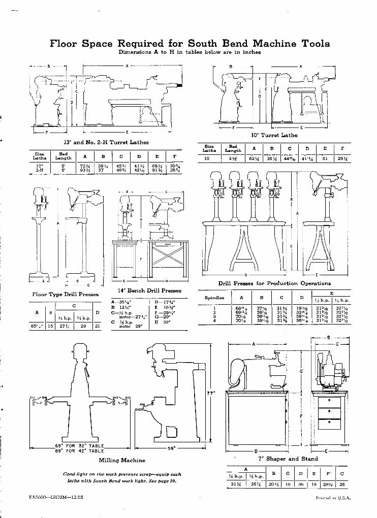
Floor Space Required for South Bend Machine Tools Dimensions A to H in tables below are in inches
~>1
1:1 t ---, ~:::.::~-:~:-- '-,~.
>--------E
13" and No. 2-H Turret Lathes
Size Bed A I B C D E F Lathe Length
13" S' 72 !" I 39!i 4S!,{ 41 y:! 68y:! 30'" 2·H 6' 93)" 37 46 3.{ 42'-f 81 y:! 28'"
IL--0 --------l I c
Floor Type Drill Presses 14" Bench Drill Presses
A
65(116"
~::j!..--~ c-.... J
B
IS
C
73 h,p, I y:! h,p,
27!': 29
D
21
A-35'{," B-12!i" C-Ji h.p.
motor-27 ~i" C-y:! h.p.
motor-29"
69" FOR 32" TABLE f-4----89" FOR 42" TABLE-----t
Milling Machine
D-17!i" E -1O!i" F -29'i" G-20" H-32"
Good light on the work prevents scrap-equip each
lathe with South Bend work light. See page 59.
KA5600-LROXM-12-55
Size Lathe
10
F
Bed Length
3y:!'
1----- E: ------I
10" Turret Lathe
A I B I C I DIE I F 62!i 35!i 44'% 411% 51 29!i
Drill Presses for Production Operations
I_A E Spindles B C D
73 h.p. y:! h.p. ------
1
I 681'~, 37% 31% 191% 31''-f 32'%
2 69131, 38'{. 31% 3215/ 16 31'\{, 32'% 3 70\{, 381\{, 31% 581% 31'\{, 32'% 4 70 '.{, 3811~, 31% 5815~6 31''-f 32",{,
77"
f
•
~---D---~ 7" Shaper and Stand
Printed in U.S,A.