Souriau 851-Series Connector Catalog
106
851 Series MIL-DTL-26482 Connectors
-
Upload
muhammad-ayaz-zakir -
Category
Documents
-
view
404 -
download
20
description
231
Transcript of Souriau 851-Series Connector Catalog
851 SeriesMIL-DTL-26482 Connectors

3
851
Sommaire / Contents
• Sommaire / Contents...............................................................• Etendue de la gamme / Product Overview......................• Présentation / Presentation....................................................• Description / Description........................................................• Tableau comparatif références SOURIAU et normes équivalentes / Cross reference list......................................• Caractéristiques techniques / Technical characteristics.• Contacts / Contacts ................................................................• Références / Ordering information......................................• Arrangements / Contact layouts..........................................• Positionnements / Orientations.............................................• Encombrements Connecteurs Etanches / Dimensions Environmental Connectors.....................................................• Encombrements Connecteurs Hermétiques / Dimen- sions Hermetic Connectors.............................................................• Encombrements Connecteurs pour connexions enrou- lées et à picots droits / Dimensions Wire-wrap and PC tail Connectors.......................................................................................• Perçage cloison / Panel cut-out............................................
33
4-56
7-89
1011-1314-15
16
17-38
39-40
40-4141
• Accessoires / Accessories.....................................................• Bouchons / Caps.......................................................................• Références des raccords / Backshell ordering information...................................................................................• Outillages / Tools.......................................................................• Notice de câblage / Wiring instructions............................• Sertissage / Crimping...............................................................• Schémas d’implantations pour circuits imprimés / Coordinates for PC tail.............................................................• Prise largable push-pull / Push-pull lanyard release plug................................................................................................• Connecteurs filtres 8F51 / 8F51 filter connector...........• Connecteurs spécifiques & accessoires SNC / Specific products & SNC accessories..................................................• Traversée de cloison 851 RJ45 / 851 RJ45 feedthru..• Traversée de cloison 851 USB / 851 USB feedtrhu.....• 8XE / 8XE....................................................................................• Protection sans cadmium / Cadmium free plating.........
4244-45
46-4748-50
5152-54
55-59
60-6162
6365-6869-7273-76
77
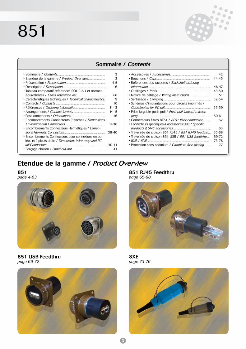
851page 4-63
851 RJ45 Feedthrupage 65-68
851 USB Feedthrupage 69-72
8XEpage 73-76
Etendue de la gamme / Product Overview
4
851
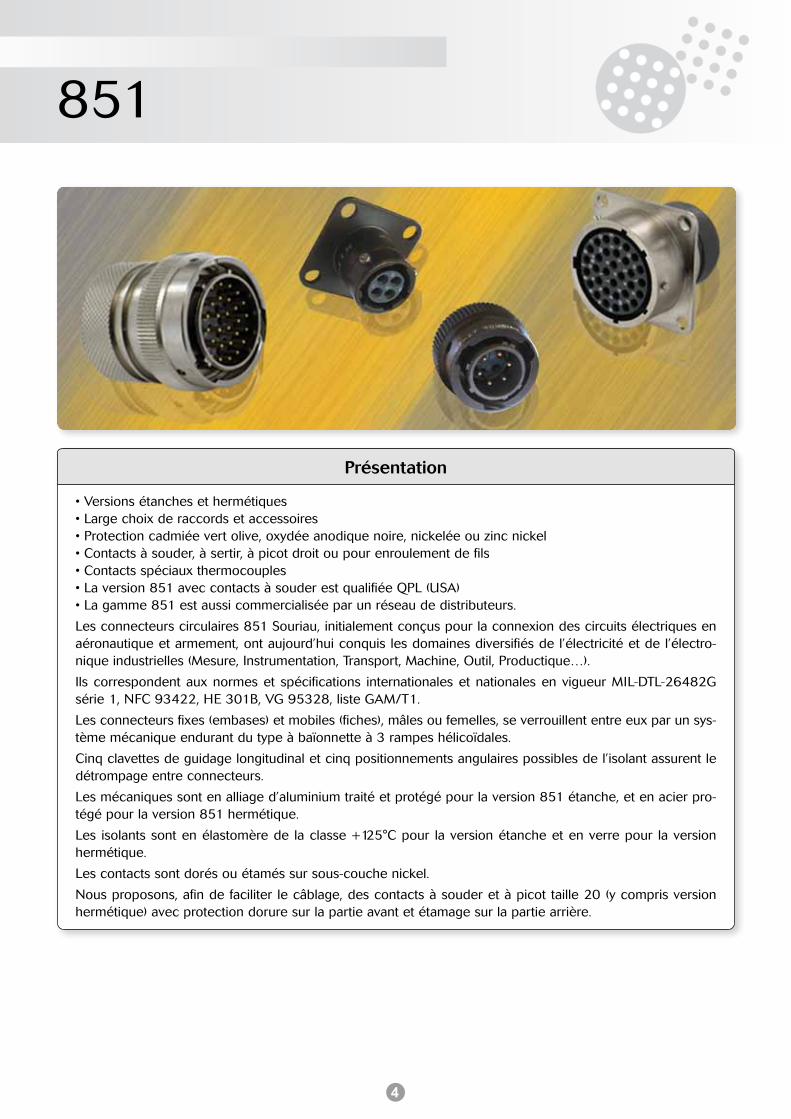
Présentation
• Versions étanches et hermétiques• Large choix de raccords et accessoires• Protection cadmiée vert olive, oxydée anodique noire, nickelée ou zinc nickel• Contacts à souder, à sertir, à picot droit ou pour enroulement de fils• Contacts spéciaux thermocouples• La version 851 avec contacts à souder est qualifiée QPL (USA)• La gamme 851 est aussi commercialisée par un réseau de distributeurs.
Les connecteurs circulaires 851 Souriau, initialement conçus pour la connexion des circuits électriques en aéronautique et armement, ont aujourd’hui conquis les domaines diversifiés de l’électricité et de l’électro-nique industrielles (Mesure, Instrumentation, Transport, Machine, Outil, Productique…).
Ils correspondent aux normes et spécifications internationales et nationales en vigueur MIL-DTL-26482G série 1, NFC 93422, HE 301B, VG 95328, liste GAM/T1.
Les connecteurs fixes (embases) et mobiles (fiches), mâles ou femelles, se verrouillent entre eux par un sys-tème mécanique endurant du type à baïonnette à 3 rampes hélicoïdales.
Cinq clavettes de guidage longitudinal et cinq positionnements angulaires possibles de l’isolant assurent le détrompage entre connecteurs.
Les mécaniques sont en alliage d’aluminium traité et protégé pour la version 851 étanche, et en acier pro-tégé pour la version 851 hermétique.
Les isolants sont en élastomère de la classe +125°C pour la version étanche et en verre pour la version hermétique.
Les contacts sont dorés ou étamés sur sous-couche nickel.
Nous proposons, afin de faciliter le câblage, des contacts à souder et à picot taille 20 (y compris version hermétique) avec protection dorure sur la partie avant et étamage sur la partie arrière.
5
851
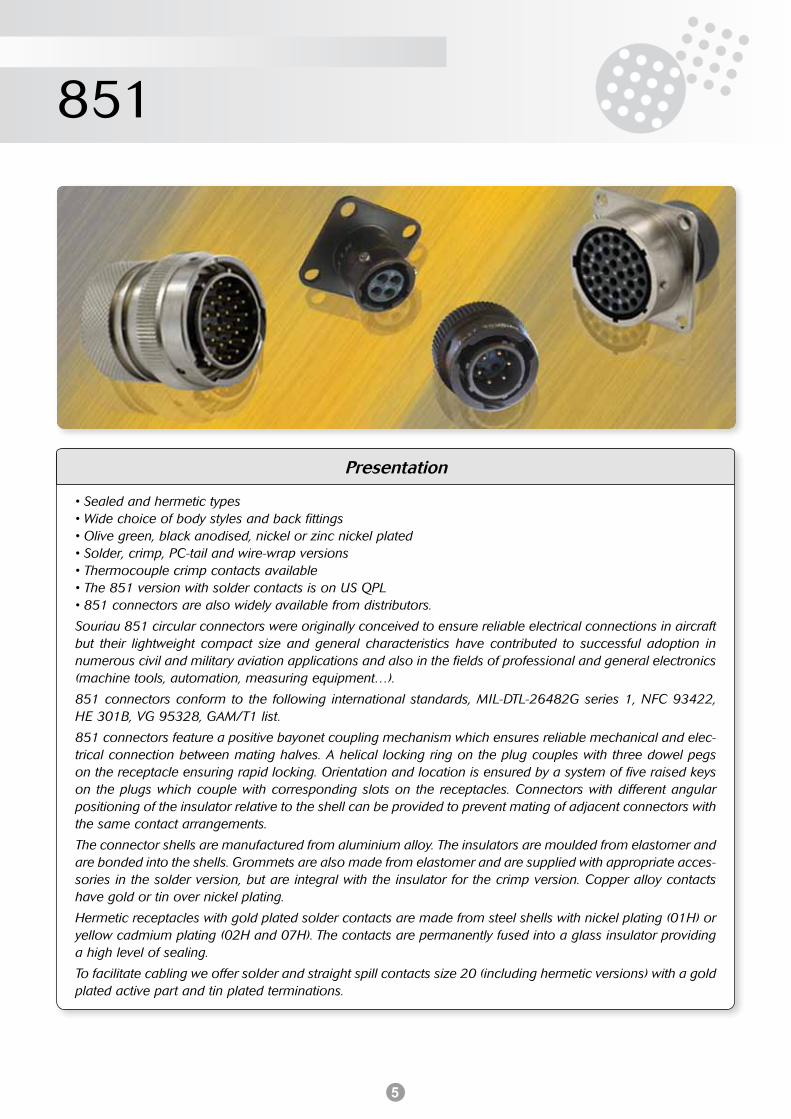
Presentation
• Sealed and hermetic types• Wide choice of body styles and back fittings• Olive green, black anodised, nickel or zinc nickel plated• Solder, crimp, PC-tail and wire-wrap versions• Thermocouple crimp contacts available• The 851 version with solder contacts is on US QPL• 851 connectors are also widely available from distributors.
Souriau 851 circular connectors were originally conceived to ensure reliable electrical connections in aircraft but their lightweight compact size and general characteristics have contributed to successful adoption in numerous civil and military aviation applications and also in the fields of professional and general electronics (machine tools, automation, measuring equipment…).
851 connectors conform to the following international standards, MIL-DTL-26482G series 1, NFC 93422, HE 301B, VG 95328, GAM/T1 list.
851 connectors feature a positive bayonet coupling mechanism which ensures reliable mechanical and elec-trical connection between mating halves. A helical locking ring on the plug couples with three dowel pegs on the receptacle ensuring rapid locking. Orientation and location is ensured by a system of five raised keys on the plugs which couple with corresponding slots on the receptacles. Connectors with different angular positioning of the insulator relative to the shell can be provided to prevent mating of adjacent connectors with the same contact arrangements.
The connector shells are manufactured from aluminium alloy. The insulators are moulded from elastomer and are bonded into the shells. Grommets are also made from elastomer and are supplied with appropriate acces-sories in the solder version, but are integral with the insulator for the crimp version. Copper alloy contacts have gold or tin over nickel plating.
Hermetic receptacles with gold plated solder contacts are made from steel shells with nickel plating (01H) or yellow cadmium plating (02H and 07H). The contacts are permanently fused into a glass insulator providing a high level of sealing.
To facilitate cabling we offer solder and straight spill contacts size 20 (including hermetic versions) with a gold plated active part and tin plated terminations.
6
851
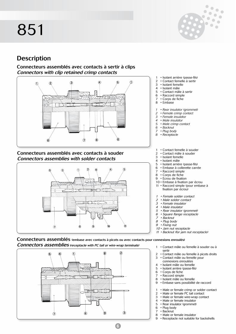
DescriptionConnecteurs assemblés avec contacts à sertir à clipsConnectors with clip retained crimp contacts
Connecteurs assemblés (embase avec contacts à picots ou avec contacts pour connexions enroulés)
Connectors assemblies (receptacle with PC tail or wire-wrap terminals)
Connecteurs assemblés avec contacts à souderConnectors assemblies with solder contacts
1 • Isolant arrière (passe-fils)2 • Contact femelle à sertir3 • Isolant femelle4 • Isolant mâle5 • Contact mâle à sertir6 • Raccord simple7 • Corps de fiche8 • Embase
1 • Rear insulator (grommet)2 • Female crimp contact3 • Female insulator4 • Male insulator5 • Male crimp contact6 • Backnut7 • Plug body8 • Receptacle
1 • Contact femelle à souder2 • Contact mâle à souder3 • Isolant femelle4 • Isolant mâle5 • Isolant arrière (passe-fils)6 • Embase à collerette carrée7 • Raccord simple8 • Corps de fiche9 • Ecrou de fixation10 • Embase à fixation par écrou11 • Raccord simple (pour embase à
fixation par écrou)
1 • Female solder contact2 • Male solder contact3 • Female insulator4 • Male insulator5 • Rear insulator (grommet)6 • Square flange receptacle7 • Backnut8 • Plug body9 • Fixing nut10 • Jam nut receptacle11 • Backnut (for jam nut receptacle)
1 • Contact mâle ou femelle à souder ou à sertir
2 • Contact mâle ou femelle à picots droits3 • Contact mâle ou femelle pour
connexions enroulées4 • Isolant mâle ou femelle5 • Isolant arrière (passe-fils)6 • Corps de fiche7 • Raccord simple8 • Isolant mâle ou femelle9 • Embase sans possibilité de raccord
1 • Male or female crimp or solder contact2 • Male or female PC tail contact3 • Male or female wire-wrap contact4 • Male or female insulator5 • Rear insulator (grommet)6 • Plug body7 • Backnut8 • Male or female insulator9 • Receptacle not suitable for backshells
7
851
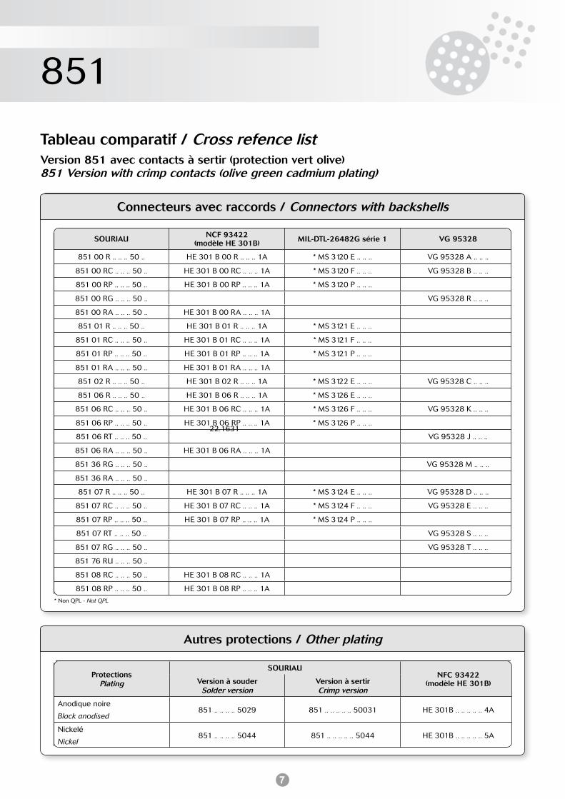
* Non QPL - Not QPL
22.1631
Connecteurs avec raccords / Connectors with backshells
SOURIAU NCF 93422(modèle HE 301B) MIL-DTL-26482G série 1 VG 95328
851 00 R .. .. .. 50 .. HE 301 B 00 R .. .. .. 1A * MS 3120 E .. .. .. VG 95328 A .. .. ..
851 00 RC .. .. .. 50 .. HE 301 B 00 RC .. .. .. 1A * MS 3120 F .. .. .. VG 95328 B .. .. ..
851 00 RP .. .. .. 50 .. HE 301 B 00 RP .. .. .. 1A * MS 3120 P .. .. ..
851 00 RG .. .. .. 50 .. VG 95328 R .. .. ..
851 00 RA .. .. .. 50 .. HE 301 B 00 RA .. .. .. 1A
851 01 R .. .. .. 50 .. HE 301 B 01 R .. .. .. 1A * MS 3121 E .. .. ..
851 01 RC .. .. .. 50 .. HE 301 B 01 RC .. .. .. 1A * MS 3121 F .. .. ..
851 01 RP .. .. .. 50 .. HE 301 B 01 RP .. .. .. 1A * MS 3121 P .. .. ..
851 01 RA .. .. .. 50 .. HE 301 B 01 RA .. .. .. 1A
851 02 R .. .. .. 50 .. HE 301 B 02 R .. .. .. 1A * MS 3122 E .. .. .. VG 95328 C .. .. ..
851 06 R .. .. .. 50 .. HE 301 B 06 R .. .. .. 1A * MS 3126 E .. .. ..
851 06 RC .. .. .. 50 .. HE 301 B 06 RC .. .. .. 1A * MS 3126 F .. .. .. VG 95328 K .. .. ..
851 06 RP .. .. .. 50 .. HE 301 B 06 RP .. .. .. 1A * MS 3126 P .. .. ..
851 06 RT .. .. .. 50 .. VG 95328 J .. .. ..
851 06 RA .. .. .. 50 .. HE 301 B 06 RA .. .. .. 1A
851 36 RG .. .. .. 50 .. VG 95328 M .. .. ..
851 36 RA .. .. .. 50 ..
851 07 R .. .. .. 50 .. HE 301 B 07 R .. .. .. 1A * MS 3124 E .. .. .. VG 95328 D .. .. ..
851 07 RC .. .. .. 50 .. HE 301 B 07 RC .. .. .. 1A * MS 3124 F .. .. .. VG 95328 E .. .. ..
851 07 RP .. .. .. 50 .. HE 301 B 07 RP .. .. .. 1A * MS 3124 P .. .. ..
851 07 RT .. .. .. 50 .. VG 95328 S .. .. ..
851 07 RG .. .. .. 50 .. VG 95328 T .. .. ..
851 76 RU .. .. .. 50 ..
851 08 RC .. .. .. 50 .. HE 301 B 08 RC .. .. .. 1A
851 08 RP .. .. .. 50 .. HE 301 B 08 RP .. .. .. 1A
Tableau comparatif / Cross refence listVersion 851 avec contacts à sertir (protection vert olive)851 Version with crimp contacts (olive green cadmium plating)
Autres protections / Other plating
ProtectionsPlating
SOURIAUNFC 93422
(modèle HE 301B)Version à souderSolder version
Version à sertirCrimp version
Anodique noire
Black anodised851 .. .. .. .. 5029 851 .. .. .. .. .. 50031 HE 301B .. .. .. .. .. 4A
Nickelé
Nickel851 .. .. .. .. 5044 851 .. .. .. .. .. 5044 HE 301B .. .. .. .. .. 5A
8
851
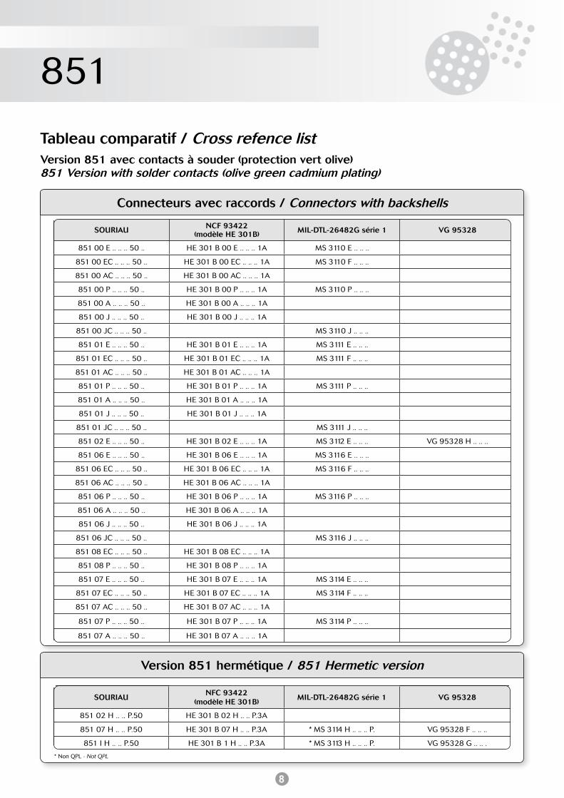
Connecteurs avec raccords / Connectors with backshells
SOURIAU NCF 93422(modèle HE 301B) MIL-DTL-26482G série 1 VG 95328
851 00 E .. .. .. 50 .. HE 301 B 00 E .. .. .. 1A MS 3110 E .. .. ..
851 00 EC .. .. .. 50 .. HE 301 B 00 EC .. .. .. 1A MS 3110 F .. .. ..
851 00 AC .. .. .. 50 .. HE 301 B 00 AC .. .. .. 1A
851 00 P .. .. .. 50 .. HE 301 B 00 P .. .. .. 1A MS 3110 P .. .. ..
851 00 A .. .. .. 50 .. HE 301 B 00 A .. .. .. 1A
851 00 J .. .. .. 50 .. HE 301 B 00 J .. .. .. 1A
851 00 JC .. .. .. 50 .. MS 3110 J .. .. ..
851 01 E .. .. .. 50 .. HE 301 B 01 E .. .. .. 1A MS 3111 E .. .. ..
851 01 EC .. .. .. 50 .. HE 301 B 01 EC .. .. .. 1A MS 3111 F .. .. ..
851 01 AC .. .. .. 50 .. HE 301 B 01 AC .. .. .. 1A
851 01 P .. .. .. 50 .. HE 301 B 01 P .. .. .. 1A MS 3111 P .. .. ..
851 01 A .. .. .. 50 .. HE 301 B 01 A .. .. .. 1A
851 01 J .. .. .. 50 .. HE 301 B 01 J .. .. .. 1A
851 01 JC .. .. .. 50 .. MS 3111 J .. .. ..
851 02 E .. .. .. 50 .. HE 301 B 02 E .. .. .. 1A MS 3112 E .. .. .. VG 95328 H .. .. ..
851 06 E .. .. .. 50 .. HE 301 B 06 E .. .. .. 1A MS 3116 E .. .. ..
851 06 EC .. .. .. 50 .. HE 301 B 06 EC .. .. .. 1A MS 3116 F .. .. ..
851 06 AC .. .. .. 50 .. HE 301 B 06 AC .. .. .. 1A
851 06 P .. .. .. 50 .. HE 301 B 06 P .. .. .. 1A MS 3116 P .. .. ..
851 06 A .. .. .. 50 .. HE 301 B 06 A .. .. .. 1A
851 06 J .. .. .. 50 .. HE 301 B 06 J .. .. .. 1A
851 06 JC .. .. .. 50 .. MS 3116 J .. .. ..
851 08 EC .. .. .. 50 .. HE 301 B 08 EC .. .. .. 1A
851 08 P .. .. .. 50 .. HE 301 B 08 P .. .. .. 1A
851 07 E .. .. .. 50 .. HE 301 B 07 E .. .. .. 1A MS 3114 E .. .. ..
851 07 EC .. .. .. 50 .. HE 301 B 07 EC .. .. .. 1A MS 3114 F .. .. ..
851 07 AC .. .. .. 50 .. HE 301 B 07 AC .. .. .. 1A
851 07 P .. .. .. 50 .. HE 301 B 07 P .. .. .. 1A MS 3114 P .. .. ..
851 07 A .. .. .. 50 .. HE 301 B 07 A .. .. .. 1A
Tableau comparatif / Cross refence listVersion 851 avec contacts à souder (protection vert olive)851 Version with solder contacts (olive green cadmium plating)
Version 851 hermétique / 851 Hermetic version
SOURIAUNFC 93422
(modèle HE 301B)MIL-DTL-26482G série 1 VG 95328
851 02 H .. .. P.50 HE 301 B 02 H .. .. P.3A
851 07 H .. .. P.50 HE 301 B 07 H .. .. P.3A * MS 3114 H .. .. .. P. VG 95328 F .. .. ..
851 I H .. .. P.50 HE 301 B 1 H .. .. P.3A * MS 3113 H .. .. .. P. VG 95328 G .. .. .
* Non QPL - Not QPL
9
851
Caractéristiques techniques / Technical characteristics
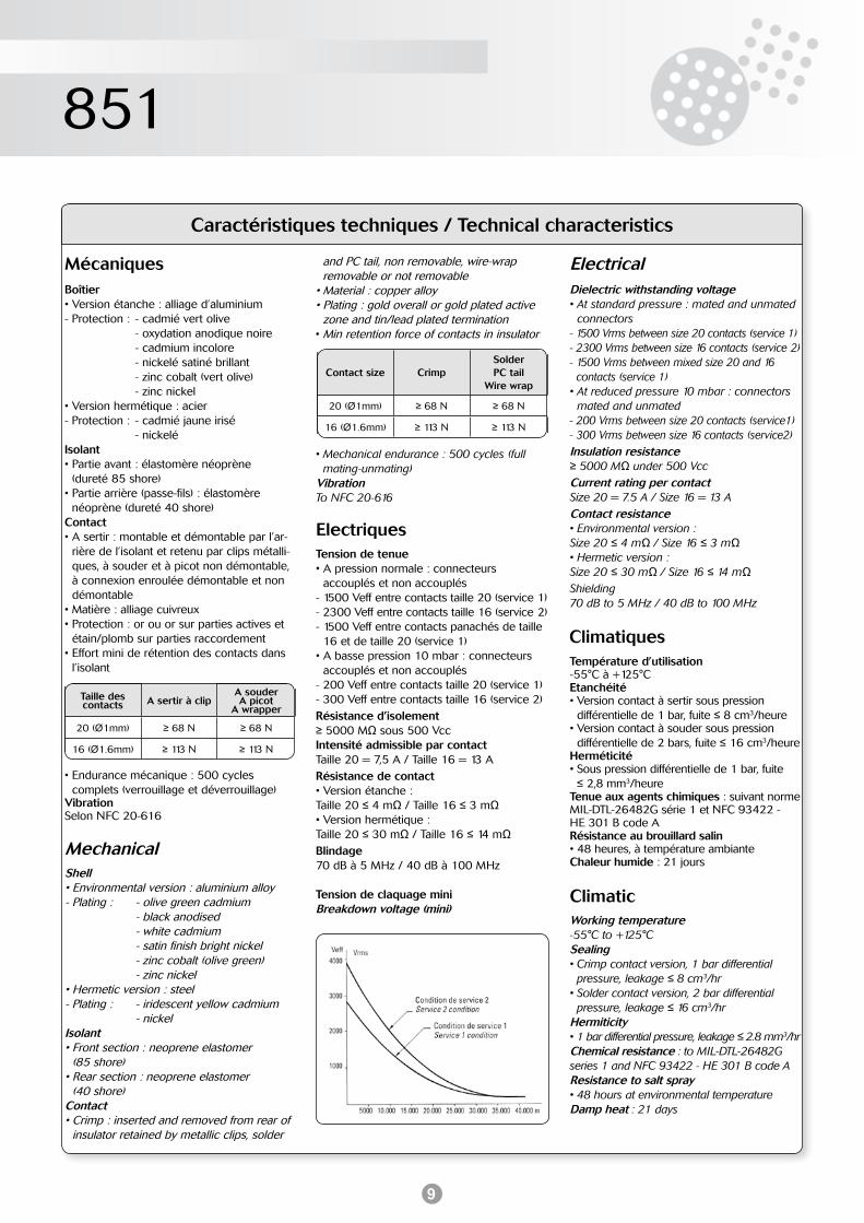
Tension de tenue• A pression normale : connecteurs
accouplés et non accouplés- 1500 Veff entre contacts taille 20 (service 1)- 2300 Veff entre contacts taille 16 (service 2)- 1500 Veff entre contacts panachés de taille
16 et de taille 20 (service 1)• A basse pression 10 mbar : connecteurs
accouplés et non accouplés- 200 Veff entre contacts taille 20 (service 1)- 300 Veff entre contacts taille 16 (service 2)Résistance d’isolement≥ 5000 MΩ sous 500 VccIntensité admissible par contactTaille 20 = 7,5 A / Taille 16 = 13 ARésistance de contact• Version étanche :Taille 20 ≤ 4 mΩ / Taille 16 ≤ 3 mΩ• Version hermétique :Taille 20 ≤ 30 mΩ / Taille 16 ≤ 14 mΩBlindage70 dB à 5 MHz / 40 dB à 100 MHz
Tension de claquage miniBreakdown voltage (mini)
Electriques
Boîtier• Version étanche : alliage d’aluminium- Protection : - cadmié vert olive - oxydation anodique noire - cadmium incolore - nickelé satiné brillant - zinc cobalt (vert olive) - zinc nickel• Version hermétique : acier- Protection : - cadmié jaune irisé - nickeléIsolant• Partie avant : élastomère néoprène (dureté 85 shore)• Partie arrière (passe-fils) : élastomère néoprène (dureté 40 shore)Contact• A sertir : montable et démontable par l’ar-
rière de l’isolant et retenu par clips métalli-ques, à souder et à picot non démontable, à connexion enroulée démontable et non démontable
• Matière : alliage cuivreux• Protection : or ou or sur parties actives et
étain/plomb sur parties raccordement• Effort mini de rétention des contacts dans
l’isolant
• Endurance mécanique : 500 cycles complets (verrouillage et déverrouillage)
VibrationSelon NFC 20-616
Mécaniques
Shell• Environmental version : aluminium alloy- Plating : - olive green cadmium - black anodised - white cadmium - satin finish bright nickel - zinc cobalt (olive green) - zinc nickel• Hermetic version : steel- Plating : - iridescent yellow cadmium - nickelIsolant• Front section : neoprene elastomer (85 shore)• Rear section : neoprene elastomer (40 shore)Contact• Crimp : inserted and removed from rear of
insulator retained by metallic clips, solder
Mechanical
Taille des contacts A sertir à clip
A souderA picot
A wrapper
20 (Ø1mm) ≥ 68 N ≥ 68 N
16 (Ø1.6mm) ≥ 113 N ≥ 113 N
Contact size CrimpSolderPC tail
Wire wrap
20 (Ø1mm) ≥ 68 N ≥ 68 N
16 (Ø1.6mm) ≥ 113 N ≥ 113 N
Working temperature-55°C to +125°CSealing• Crimp contact version, 1 bar differential
pressure, leakage ≤ 8 cm3/hr• Solder contact version, 2 bar differential
pressure, leakage ≤ 16 cm3/hrHermiticity• 1 bar differential pressure, leakage ≤ 2.8 mm3/hrChemical resistance : to MIL-DTL-26482G series 1 and NFC 93422 - HE 301 B code AResistance to salt spray • 48 hours at environmental temperatureDamp heat : 21 days
Climatic
• Mechanical endurance : 500 cycles (full mating-unmating)
VibrationTo NFC 20-616
Dielectric withstanding voltage• At standard pressure : mated and unmated
connectors- 1500 Vrms between size 20 contacts (service 1)- 2300 Vrms between size 16 contacts (service 2)- 1500 Vrms between mixed size 20 and 16
contacts (service 1)• At reduced pressure 10 mbar : connectors
mated and unmated- 200 Vrms between size 20 contacts (service1)- 300 Vrms between size 16 contacts (service2)Insulation resistance≥ 5000 MΩ under 500 VccCurrent rating per contactSize 20 = 7.5 A / Size 16 = 13 AContact resistance• Environmental version :Size 20 ≤ 4 mΩ / Size 16 ≤ 3 mΩ• Hermetic version :Size 20 ≤ 30 mΩ / Size 16 ≤ 14 mΩShielding70 dB to 5 MHz / 40 dB to 100 MHz
Température d’utilisation-55°C à +125°CEtanchéité• Version contact à sertir sous pression
différentielle de 1 bar, fuite ≤ 8 cm3/heure• Version contact à souder sous pression
différentielle de 2 bars, fuite ≤ 16 cm3/heureHerméticité• Sous pression différentielle de 1 bar, fuite ≤ 2,8 mm3/heureTenue aux agents chimiques : suivant norme MIL-DTL-26482G série 1 et NFC 93422 - HE 301 B code ARésistance au brouillard salin • 48 heures, à température ambianteChaleur humide : 21 jours
Climatiques
and PC tail, non removable, wire-wrap removable or not removable• Material : copper alloy• Plating : gold overall or gold plated active
zone and tin/lead plated termination• Min retention force of contacts in insulator
Electrical
10
851
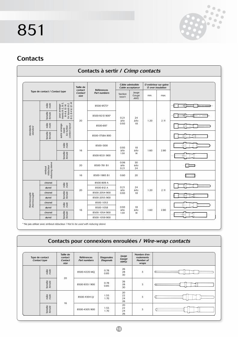
Contacts à sertir / Crimp contacts
Type de contact / Contact type
Taille decontactContact
size
RéférencesPart numbers
Câble admissibleCable acceptance
Ø extérieur sur gaineØ over insulation
Section(mm²)
JaugeGaugeAWG
min. max.
stan
dard
sst
anda
rd
mâl
em
ale
pour
arr
ange
-m
ents
8-2
, 8-3
, 8
-4 &
12
-14
for
layo
uts
8-2
, 8
-3, 8
-4 &
12
-14
20
8500-9573*
0.21à/to0.93
24à/to18
1.20 2.11
fem
elle
fem
ale
8500-9213 900*
mâl
em
ale
autr
e ar
rang
e-m
ent
for
furt
her
cont
act l
ayo
ut
8500-697
fem
elle
fem
ale
8500-1758A 900
mâl
em
ale
16
8500-13000.93à/to1.91
18à/to14
1.60 2.80
fem
elle
fem
ale
8500-9331 900
embo
ut
rédu
cteu
rre
duci
ng s
leev
e
20 8500-781 B10.06à/to0.21
30à/to24
16 8500-1985 B1 0.60 20
ther
moc
oupl
eth
erm
oco
uple
chromel
mâl
em
ale
20
8500-809 A
0.21à/to0.93
24à/to18
1.20 2.11alumel 8500-812 A
chromel
fem
elle
fem
ale 8500-2054 900
alumel 8500-2055 900
chromel
mâl
em
ale
16
8500-1053
0.93à/to1.91
18à/to14
1.60 2.80alumel 8500-1058
chromel
fem
elle
fem
ale 8500-1054 900
alumel 8500-1059 900
Contacts
Contacts pour connexions enroulées / Wire-wrap contacts
Type de contactContact type
Taille decontactContact
size
RéférencesPart numbers
DiagonalesDiagonals
JaugeGauge(AWG)
Nombre d’en-roulementsNumber of
wraps
mâl
em
ale
20
8500-4220 MQ0.780.85
262830
3
fem
elle
fem
ale
8500-9351 9000.780.85
262830
3
mâl
em
ale
16
8500-4304 LY1.551.70
20222426
3
fem
elle
fem
ale
8500-4305 9001.551.70
20222426
3
* Ne pas utiliser avec embout réducteur / Not to be used with reducing sleeve
11
851
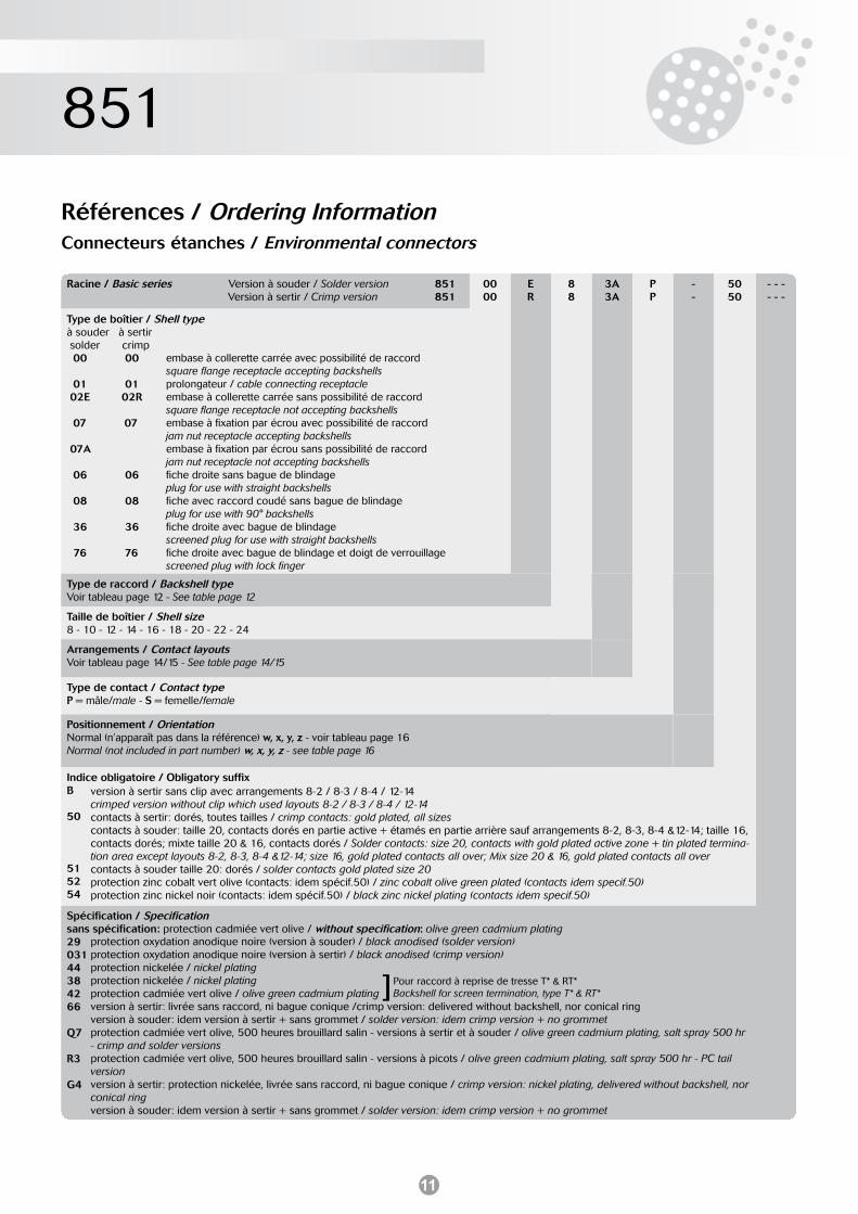
Racine / Basic series Version à souder / Solder version Version à sertir / Crimp version
851851
0000
ER
88
3A3A
PP
--
5050
- - -- - -
Type de boîtier / Shell typeà souder à sertir solder crimp 00 00 01 01 02E 02R 07 07 07A 06 06 08 08 36 36 76 76
Type de raccord / Backshell typeVoir tableau page 12 - See table page 12
Taille de boîtier / Shell size8 - 10 - 12 - 14 - 16 - 18 - 20 - 22 - 24
Arrangements / Contact layoutsVoir tableau page 14/15 - See table page 14/15
Type de contact / Contact typeP = mâle/male - S = femelle/female
Positionnement / OrientationNormal (n’apparaît pas dans la référence) w, x, y, z - voir tableau page 16Normal (not included in part number) w, x, y, z - see table page 16
Indice obligatoire / Obligatory suffixB 50
51 52 54
Spécification / Specificationsans spécification: protection cadmiée vert olive / without specification: olive green cadmium plating29 03144 38 42 66
Q7
R3
G4
Références / Ordering InformationConnecteurs étanches / Environmental connectors
embase à collerette carrée avec possibilité de raccordsquare flange receptacle accepting backshellsprolongateur / cable connecting receptacleembase à collerette carrée sans possibilité de raccordsquare flange receptacle not accepting backshellsembase à fixation par écrou avec possibilité de raccordjam nut receptacle accepting backshellsembase à fixation par écrou sans possibilité de raccordjam nut receptacle not accepting backshellsfiche droite sans bague de blindageplug for use with straight backshellsfiche avec raccord coudé sans bague de blindageplug for use with 90° backshellsfiche droite avec bague de blindagescreened plug for use with straight backshellsfiche droite avec bague de blindage et doigt de verrouillagescreened plug with lock finger
version à sertir sans clip avec arrangements 8-2 / 8-3 / 8-4 / 12-14crimped version without clip which used layouts 8-2 / 8-3 / 8-4 / 12-14contacts à sertir: dorés, toutes tailles / crimp contacts: gold plated, all sizescontacts à souder: taille 20, contacts dorés en partie active + étamés en partie arrière sauf arrangements 8-2, 8-3, 8-4 &12-14; taille 16, contacts dorés; mixte taille 20 & 16, contacts dorés / Solder contacts: size 20, contacts with gold plated active zone + tin plated termina-tion area except layouts 8-2, 8-3, 8-4 &12-14; size 16, gold plated contacts all over; Mix size 20 & 16, gold plated contacts all overcontacts à souder taille 20: dorés / solder contacts gold plated size 20protection zinc cobalt vert olive (contacts: idem spécif.50) / zinc cobalt olive green plated (contacts idem specif.50)protection zinc nickel noir (contacts: idem spécif.50) / black zinc nickel plating (contacts idem specif.50)
protection oxydation anodique noire (version à souder) / black anodised (solder version)protection oxydation anodique noire (version à sertir) / black anodised (crimp version)protection nickelée / nickel platingprotection nickelée / nickel platingprotection cadmiée vert olive / olive green cadmium platingversion à sertir: livrée sans raccord, ni bague conique /crimp version: delivered without backshell, nor conical ringversion à souder: idem version à sertir + sans grommet / solder version: idem crimp version + no grommetprotection cadmiée vert olive, 500 heures brouillard salin - versions à sertir et à souder / olive green cadmium plating, salt spray 500 hr- crimp and solder versionsprotection cadmiée vert olive, 500 heures brouillard salin - versions à picots / olive green cadmium plating, salt spray 500 hr - PC tail versionversion à sertir: protection nickelée, livrée sans raccord, ni bague conique / crimp version: nickel plating, delivered without backshell, norconical ringversion à souder: idem version à sertir + sans grommet / solder version: idem crimp version + no grommet
]Pour raccord à reprise de tresse T* & RT*Backshell for screen termination, type T* & RT*
12
851
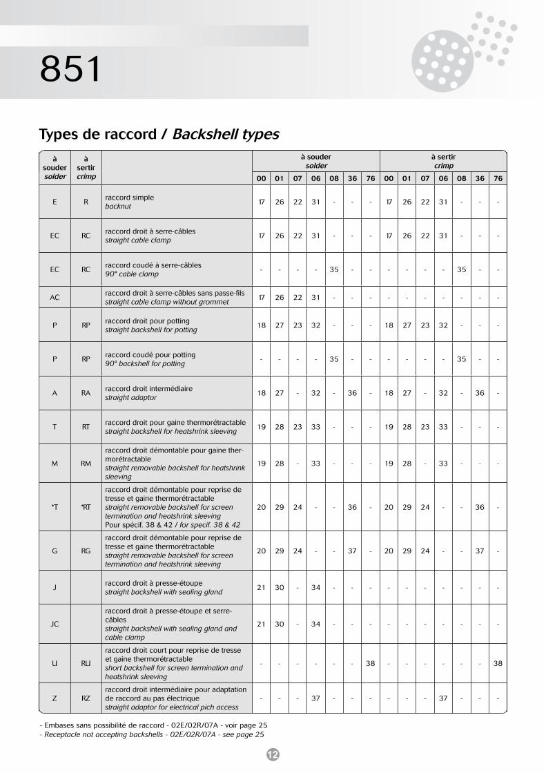
Types de raccord / Backshell types
- Embases sans possibilité de raccord - 02E/02R/07A - voir page 25- Receptacle not accepting backshells - 02E/02R/07A - see page 25
àsoudersolder
àsertircrimp
à soudersolder
à sertircrimp
00 01 07 06 08 36 76 00 01 07 06 08 36 76
E Rraccord simplebacknut
17 26 22 31 - - - 17 26 22 31 - - -
EC RCraccord droit à serre-câblesstraight cable clamp
17 26 22 31 - - - 17 26 22 31 - - -
EC RCraccord coudé à serre-câbles90° cable clamp
- - - - 35 - - - - - - 35 - -
ACraccord droit à serre-câbles sans passe-filsstraight cable clamp without grommet
17 26 22 31 - - - - - - - - - -
P RPraccord droit pour pottingstraight backshell for potting
18 27 23 32 - - - 18 27 23 32 - - -
P RPraccord coudé pour potting90° backshell for potting
- - - - 35 - - - - - - 35 - -
A RAraccord droit intermédiairestraight adaptor
18 27 - 32 - 36 - 18 27 - 32 - 36 -
T RTraccord droit pour gaine thermorétractablestraight backshell for heatshrink sleeving
19 28 23 33 - - - 19 28 23 33 - - -
M RM
raccord droit démontable pour gaine ther-morétractablestraight removable backshell for heatshrink sleeving
19 28 - 33 - - - 19 28 - 33 - - -
*T *RT
raccord droit démontable pour reprise de tresse et gaine thermorétractablestraight removable backshell for screen termination and heatshrink sleevingPour spécif. 38 & 42 / for specif. 38 & 42
20 29 24 - - 36 - 20 29 24 - - 36 -
G RG
raccord droit démontable pour reprise de tresse et gaine thermorétractablestraight removable backshell for screen termination and heatshrink sleeving
20 29 24 - - 37 - 20 29 24 - - 37 -
Jraccord droit à presse-étoupestraight backshell with sealing gland
21 30 - 34 - - - - - - - - - -
JC
raccord droit à presse-étoupe et serre-câblesstraight backshell with sealing gland and cable clamp
21 30 - 34 - - - - - - - - - -
U RU
raccord droit court pour reprise de tresse et gaine thermorétractableshort backshell for screen termination and heatshrink sleeving
- - - - - - 38 - - - - - - 38
Z RZraccord droit intermédiaire pour adaptation de raccord au pas électriquestraight adaptor for electrical pich access
- - - 37 - - - - - - 37 - - -
13
851
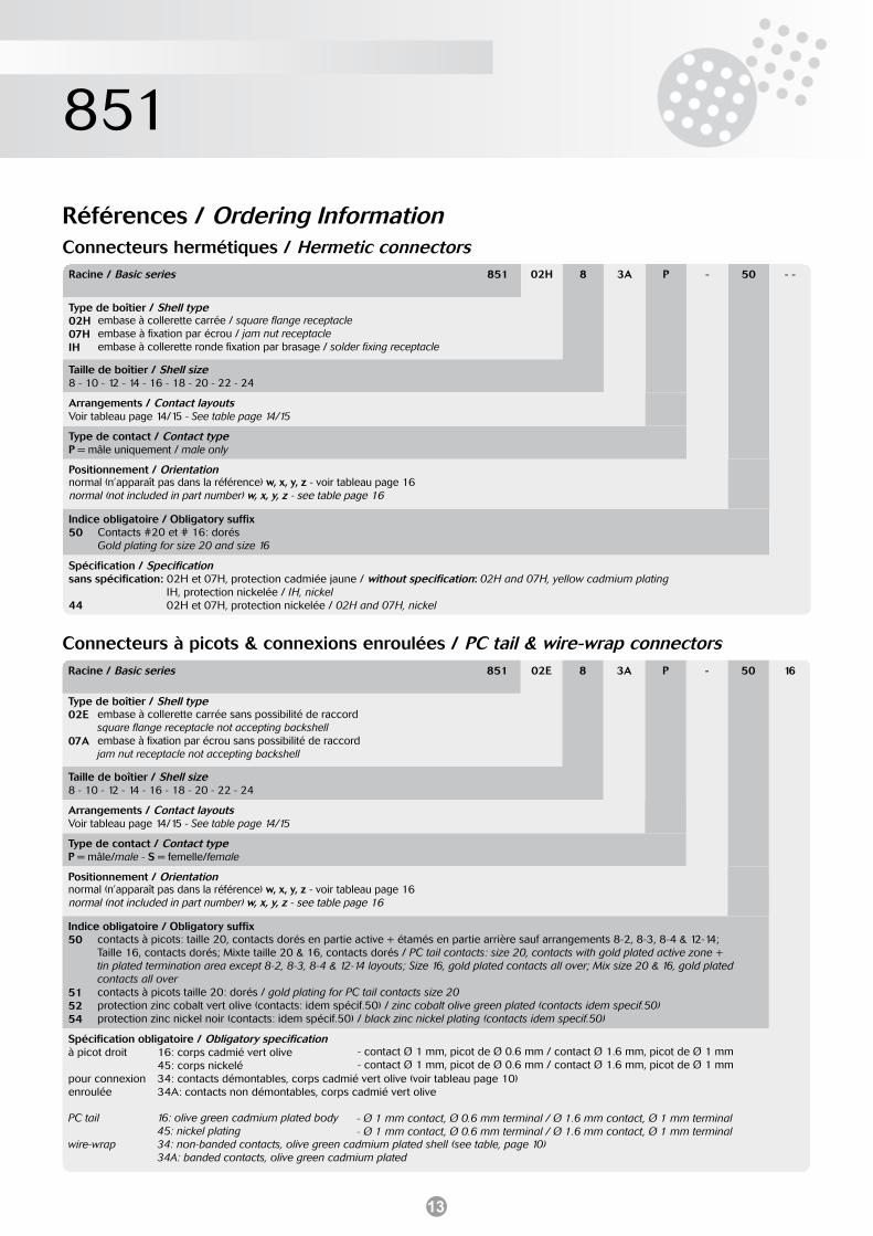
Références / Ordering InformationConnecteurs hermétiques / Hermetic connectorsRacine / Basic series 851 02H 8 3A P - 50 - -
Type de boîtier / Shell type02H 07H IH
Taille de boîtier / Shell size8 - 10 - 12 - 14 - 16 - 18 - 20 - 22 - 24
Arrangements / Contact layoutsVoir tableau page 14/15 - See table page 14/15
Type de contact / Contact typeP = mâle uniquement / male only
Positionnement / Orientationnormal (n’apparaît pas dans la référence) w, x, y, z - voir tableau page 16normal (not included in part number) w, x, y, z - see table page 16
Indice obligatoire / Obligatory suffix50
Spécification / Specificationsans spécification: 02H et 07H, protection cadmiée jaune / without specification: 02H and 07H, yellow cadmium platingsans spécification: IH, protection nickelée / IH, nickel44 02H et 07H, protection nickelée / 02H and 07H, nickel
Connecteurs à picots & connexions enroulées / PC tail & wire-wrap connectorsRacine / Basic series 851 02E 8 3A P - 50 16
Type de boîtier / Shell type02E
07A
Taille de boîtier / Shell size8 - 10 - 12 - 14 - 16 - 18 - 20 - 22 - 24
Arrangements / Contact layoutsVoir tableau page 14/15 - See table page 14/15
Type de contact / Contact typeP = mâle/male - S = femelle/female
Positionnement / Orientationnormal (n’apparaît pas dans la référence) w, x, y, z - voir tableau page 16normal (not included in part number) w, x, y, z - see table page 16
Indice obligatoire / Obligatory suffix50
51 52 54
Spécification obligatoire / Obligatory specificationà picot droit à picot droit pour connexion enroulée
PC tail à picot droit wire-wrap
embase à collerette carrée / square flange receptacleembase à fixation par écrou / jam nut receptacleembase à collerette ronde fixation par brasage / solder fixing receptacle
Contacts #20 et # 16: dorésGold plating for size 20 and size 16
embase à collerette carrée sans possibilité de raccordsquare flange receptacle not accepting backshellembase à fixation par écrou sans possibilité de raccordjam nut receptacle not accepting backshell
contacts à picots: taille 20, contacts dorés en partie active + étamés en partie arrière sauf arrangements 8-2, 8-3, 8-4 & 12-14; Taille 16, contacts dorés; Mixte taille 20 & 16, contacts dorés / PC tail contacts: size 20, contacts with gold plated active zone + tin plated termination area except 8-2, 8-3, 8-4 & 12-14 layouts; Size 16, gold plated contacts all over; Mix size 20 & 16, gold plated contacts all over contacts à picots taille 20: dorés / gold plating for PC tail contacts size 20protection zinc cobalt vert olive (contacts: idem spécif.50) / zinc cobalt olive green plated (contacts idem specif.50)protection zinc nickel noir (contacts: idem spécif.50) / black zinc nickel plating (contacts idem specif.50)
16: corps cadmié vert olive 45: corps nickelé 34: contacts démontables, corps cadmié vert olive (voir tableau page 10)34A: contacts non démontables, corps cadmié vert olive
16: olive green cadmium plated body45: nickel plating 34: non-banded contacts, olive green cadmium plated shell (see table, page 10)34A: banded contacts, olive green cadmium plated
- Ø 1 mm contact, Ø 0.6 mm terminal / Ø 1.6 mm contact, Ø 1 mm terminal- Ø 1 mm contact, Ø 0.6 mm terminal / Ø 1.6 mm contact, Ø 1 mm terminal
- contact Ø 1 mm, picot de Ø 0.6 mm / contact Ø 1.6 mm, picot de Ø 1 mm- contact Ø 1 mm, picot de Ø 0.6 mm / contact Ø 1.6 mm, picot de Ø 1 mm
14
851
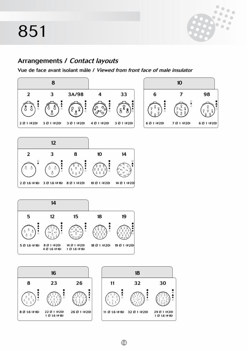
Arrangements / Contact layoutsVue de face avant isolant mâle / Viewed from front face of male insulator
2
2 Ø 1 (#20)
3
3 Ø 1 (#20)
3A/98
3 Ø 1 (#20)
4
4 Ø 1 (#20)
33
3 Ø 1 (#20)
6
6 Ø 1 (#20)
7
7 Ø 1 (#20)
98
6 Ø 1 (#20)
12
3
3 Ø 1.6 (#16)
8
8 Ø 1 (#20)
10
10 Ø 1 (#20)
14
14 Ø 1 (#20)
2
2 Ø 1.6 (#16)
14
12
8 Ø 1 (#20) 4 Ø 1.6 (#16)
15
14 Ø 1 (#20) 1 Ø 1.6 (#16)
18
18 Ø 1 (#20)
19
19 Ø 1 (#20)
5
5 Ø 1.6 (#16)
16
8
8 Ø 1.6 (#16)
23
22 Ø 1 (#20)1 Ø 1.6 (#16)
26
26 Ø 1 (#20)
18
11
11 Ø 1.6 (#16)
32
32 Ø 1 (#20)
30
29 Ø 1 (#20) 1 Ø 1.6 (#16)
♦
♦
♦
♦
♦
♦
♦
♦
♦
♦
♦
♦
♦
♦
♦
♦
♦
♦
♦
♦
♦
♦
♦
+ ♦
8 10
15
851
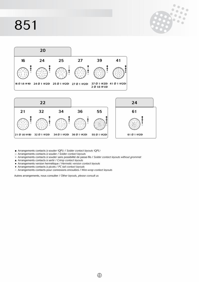
20
16
16 Ø 1.6 (#16)
39
37 Ø 1 (#20) 2 Ø 1.6 (#1.6)
41
41 Ø 1 (#20)
24
24 Ø 1 (#20)
25
25 Ø 1 (#20)
22
36
36 Ø 1 (#20)
55
55 Ø 1 (#20)
32
32 Ø 1 (#20)
34
34 Ø 1 (#20)
21
21 Ø 1.6 (#16)
24
61
61 Ø 1 (#20)
27
27 Ø 1 (#20)
Arrangements contacts à souder (QPL) / Solder contact layouts (QPL)Arrangements contacts à souder / Solder contact layoutsArrangements contacts à souder sans possibilité de passe-fils / Solder contact layouts without grommetArrangements contacts à sertir / Crimp contact layoutsArrangements version hermétique / Hermetic version contact layoutsArrangements contacts à picots / PC tail contact layoutsArrangements contacts pour connexions enroulées / Wire-wrap contact layouts
+ ♦
♦
♦
+ ♦
+ ♦
♦
♦
♦
+ ♦
♦
♦
♦
♦
Autres arrangements, nous consulter / Other layouts, please consult us
16
851
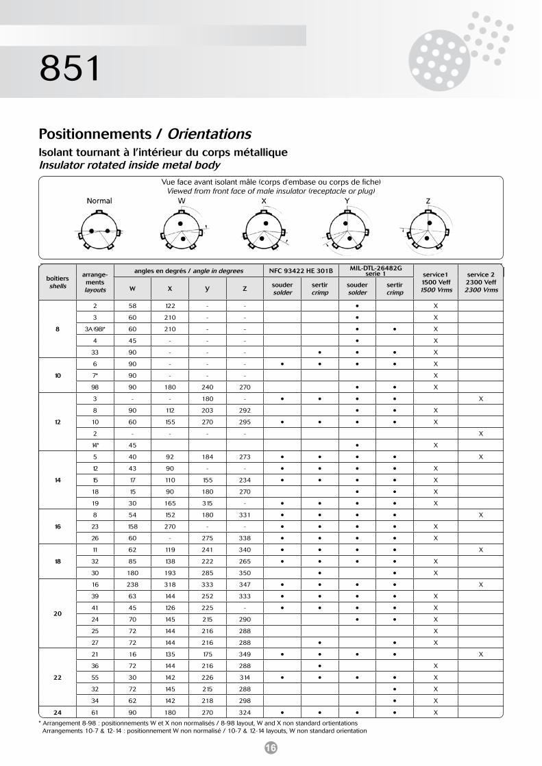
Positionnements / OrientationsIsolant tournant à l’intérieur du corps métalliqueInsulator rotated inside metal body
Vue face avant isolant mâle (corps d’embase ou corps de fiche)Viewed from front face of male insulator (receptacle or plug)
boîtiersshells
arrange-mentslayouts
angles en degrés / angle in degrees NFC 93422 HE 301B MIL-DTL-26482G serie 1 service1
1500 Veff1500 Vrms
service 22300 Veff2300 VrmsW X Y Z
soudersolder
sertircrimp
soudersolder
sertircrimp
8
2 58 122 - - • X
3 60 210 - - • X
3A (98)* 60 210 - - • • X
4 45 - - - • X
33 90 - - - • • • X
10
6 90 - - - • • • • X
7* 90 - - - X
98 90 180 240 270 • • X
12
3 - - 180 - • • • • X
8 90 112 203 292 • • X
10 60 155 270 295 • • • • X
2 - - - - X
14* 45 • X
14
5 40 92 184 273 • • • • X
12 43 90 - - • • • • X
15 17 110 155 234 • • • • X
18 15 90 180 270 • • X
19 30 165 315 - • • • • X
16
8 54 152 180 331 • • • • X
23 158 270 - - • • • • X
26 60 - 275 338 • • • • X
18
11 62 119 241 340 • • • • X
32 85 138 222 265 • • • • X
30 180 193 285 350 • • X
20
16 238 318 333 347 • • • • X
39 63 144 252 333 • • • • X
41 45 126 225 - • • • • X
24 70 145 215 290 • • X
25 72 144 216 288 X
27 72 144 216 288 • • X
22
21 16 135 175 349 • • • • X
36 72 144 216 288 • X
55 30 142 226 314 • • • • X
32 72 145 215 288 • X
34 62 142 218 298 • X
24 61 90 180 270 324 • • • • X
* Arrangement 8-98 : positionnements W et X non normalisés / 8-98 layout, W and X non standard ortientations Arrangements 10-7 & 12-14 : positionnement W non normalisé / 10-7 & 12-14 layouts, W non standard orientation
17
851
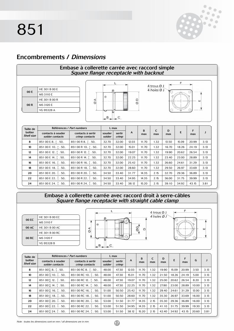
Embase à collerette carrée avec raccord simpleSquare flange receptacle with backnut
Encombrements / Dimensions
Taille de boîtier
Shell size
Références / Part numbers L max
AB
maxC
maxD
maxE
Fmax
Jcontacts à soudersolder contacts
contacts à sertircrimp contacts
souder solder
sertircrimp
8 851 00 E 8.. . 50.. 851 00 R 8.. . 50.. 32.70 32.00 12.03 11.70 1.32 13.50 15.09 20.99 3.13
10 851 00 E 10.. . 50.. 851 00 R 10.. . 50.. 32.70 32.00 15.01 11.70 1.32 16.70 18.26 24.19 3.13
12 851 00 E 12.. . 50.. 851 00 R 12.. . 50.. 32.70 32.00 19.07 11.70 1.32 19.90 20.62 26.54 3.13
14 851 00 E 14.. . 50.. 851 00 R 14.. . 50.. 32.70 32.00 22.25 11.70 1.32 23.40 23.00 28.89 3.13
16 851 00 E 16.. . 50.. 851 00 R 16.. . 50.. 32.70 32.00 25.42 11.70 1.32 26.60 24.61 31.29 3.13
18 851 00 E 18.. . 50.. 851 00 R 18.. . 50.. 32.70 32.00 28.60 11.70 1.32 29.50 26.97 33.69 3.13
20 851 00 E 20.. . 50.. 851 00 R 20.. . 50.. 34.50 33.40 31.77 14.35 2.15 32.70 29.36 36.89 3.13
22 851 00 E 22.. . 50.. 851 00 R 22.. . 50.. 34.50 33.40 34.95 14.35 2.15 36.00 31.75 39.99 3.13
24 851 00 E 24.. . 50.. 851 00 R 24.. . 50.. 34.50 33.40 38.12 15.20 2.15 39.10 34.92 43.15 3.81
00 EHE 301 B 00 E
MS 3110 E
00 R
HE 301 B 00 R
MS 3120 E
VG 95328 A
PS
PS
PS
PS
PS
PS
PS
PS
PS
PS
PS
PS
PS
PS
PS
PS
PS
PS
Embase à collerette carrée avec raccord droit à serre-câblesSquare flange receptacle with straight cable clamp
Taille de boîtier
Shell size
Références / Part numbers L max
AB
maxC
maxD
maxE
Fmax
G Jcontacts à soudersolder contacts
contacts à sertircrimp contacts
souder solder
sertircrimp
8 851 00 8.. . 50.. 851 00 RC 8.. . 50 .. 48.00 47.30 12.03 11.70 1.32 19.90 15.09 20.99 3.50 3.13
10 851 00 10.. . 50.. 851 00 RC 10.. . 50.. 48.00 47.30 15.01 11.70 1.32 21.50 18.26 24.19 5.00 3.13
12 851 00 12.. . 50.. 851 00 RC 12.. . 50.. 48.00 47.30 19.07 11.70 1.32 25.00 20.62 26.54 8.20 3.13
14 851 00 14.. . 50.. 851 00 RC 14.. . 50.. 48.00 47.30 22.25 11.70 1.32 27.80 23.00 28.89 10.00 3.13
16 851 00 16.. . 50.. 851 00 RC 16.. . 50.. 51.00 50.50 25.42 11.70 1.32 29.40 24.61 31.29 13.00 3.13
18 851 00 18.. . 50.. 851 00 RC 18.. . 50.. 51.00 50.50 28.60 11.70 1.32 35.30 26.97 33.69 16.00 3.13
20 851 00 20.. . 50.. 851 00 RC 20.. . 50.. 53.00 51.50 31.77 14.35 2.15 35.30 29.36 36.89 16.00 3.13
22 851 00 22.. . 50.. 851 00 RC 22.. . 50.. 53.00 51.50 34.95 14.35 2.15 41.10 31.75 39.99 19.30 3.13
24 851 00 24.. . 50.. 851 00 RC 24.. . 50.. 53.00 51.50 38.12 15.20 2.15 42.40 34.92 43.15 20.60 3.81
00 ECHE 301 B 00 EC
MS 3110 F
00 AC HE 301 B 00 AC
00 RC
HE 301 B 00 RC
MS 3120 F
VG 95328 B
PS
PS
PS
PS
PS
PS
PS
PS
PS
ECAC
ECAC
ECAC
ECAC
ECAC
ECAC
ECAC
ECAC
ECAC
PS
PS
PS
PS
PS
PS
PS
PS
PS
Note : toutes les dimensions sont en mm / all dimensions are in mm
18
851
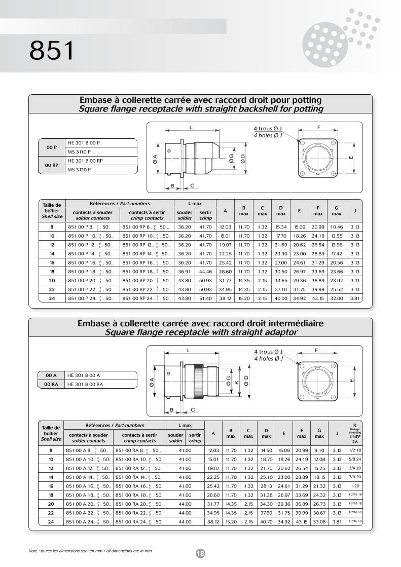
Embase à collerette carrée avec raccord droit pour pottingSquare flange receptacle with straight backshell for potting
00 PHE 301 B 00 P
MS 3110 P
00 RPHE 301 B 00 RP
MS 3120 P
Taille de boîtier
Shell size
Références / Part numbers L max
AB
maxC
maxD
maxE
Fmax
Gmax
Jcontacts à soudersolder contacts
contacts à sertircrimp contacts
souder solder
sertircrimp
8 851 00 P 8.. . 50.. 851 00 RP 8.. . 50 .. 36.20 41.70 12.03 11.70 1.32 15.34 15.09 20.99 10.46 3.13
10 851 00 P 10.. . 50.. 851 00 RP 10.. . 50.. 36.20 41.70 15.01 11.70 1.32 17.70 18.26 24.19 13.55 3.13
12 851 00 P 12.. . 50.. 851 00 RP 12.. . 50.. 36.20 41.70 19.07 11.70 1.32 21.69 20.62 26.54 13.96 3.13
14 851 00 P 14.. . 50.. 851 00 RP 14.. . 50.. 36.20 41.70 22.25 11.70 1.32 23.90 23.00 28.89 17.42 3.13
16 851 00 P 16.. . 50.. 851 00 RP 16.. . 50.. 36.20 41.70 25.42 11.70 1.32 27.00 24.61 31.29 20.56 3.13
18 851 00 P 18.. . 50.. 851 00 RP 18.. . 50.. 36.91 44.46 28.60 11.70 1.32 30.50 26.97 33.69 23.66 3.13
20 851 00 P 20.. . 50.. 851 00 RP 20.. . 50.. 43.80 50.93 31.77 14.35 2.15 33.65 29.36 36.89 23.92 3.13
22 851 00 P 22.. . 50.. 851 00 RP 22.. . 50.. 43.80 50.93 34.95 14.35 2.15 37.10 31.75 39.99 25.52 3.13
24 851 00 P 24.. . 50.. 851 00 RP 24.. . 50.. 43.80 51.40 38.12 15.20 2.15 40.00 34.92 43.15 32.00 3.81
PS
PS
PS
PS
PS
PS
PS
PS
PS
PS
PS
PS
PS
PS
PS
PS
PS
PS
Embase à collerette carrée avec raccord droit intermédiaireSquare flange receptacle with straight adaptor
00 A HE 301 B 00 A
00 RA HE 301 B 00 RA
Taille de boîtier
Shell size
Références / Part numbers L max
AB
maxC
maxD
maxE
Fmax
Gmax
J
Kfiletage
threading
UNEF 2A
contacts à soudersolder contacts
contacts à sertircrimp contacts
souder solder
sertircrimp
8 851 00 A 8.. . 50.. 851 00 RA 8.. . 50 .. 41.00 12.03 11.70 1.32 14.50 15.09 20.99 9.10 3.13 1/2 18
10 851 00 A 10.. . 50.. 851 00 RA 10.. . 50.. 41.00 15.01 11.70 1.32 18.70 18.26 24.19 12.08 3.13 5/8 24
12 851 00 A 12.. . 50.. 851 00 RA 12.. . 50.. 41.00 19.07 11.70 1.32 21.70 20.62 26.54 15.25 3.13 3/4 20
14 851 00 A 14.. . 50.. 851 00 RA 14.. . 50.. 41.00 22.25 11.70 1.32 25.10 23.00 28.89 18.15 3.13 7/8 20
16 851 00 A 16.. . 50.. 851 00 RA 16.. . 50.. 41.00 25.42 11.70 1.32 28.13 24.61 31.29 21.32 3.13 1-20
18 851 00 A 18.. . 50.. 851 00 RA 18.. . 50.. 41.00 28.60 11.70 1.32 31.38 26.97 33.69 24.32 3.13 1-3/16 18
20 851 00 A 20.. . 50.. 851 00 RA 20.. . 50.. 44.00 31.77 14.35 2.15 34.30 29.36 36.89 26.73 3.13 1-3/16 18
22 851 00 A 22.. . 50.. 851 00 RA 22.. . 50.. 44.00 34.95 14.35 2.15 37.60 31.75 39.99 30.67 3.13 1-7/16 18
24 851 00 A 24.. . 50.. 851 00 RA 24.. . 50.. 44.00 38.12 15.20 2.15 40.70 34.92 43.15 33.08 3.81 1-7/16 18
PS
PS
PS
PS
PS
PS
PS
PS
PS
PS
PS
PS
PS
PS
PS
PS
PS
PS
Note : toutes les dimensions sont en mm / all dimensions are in mm
19
851
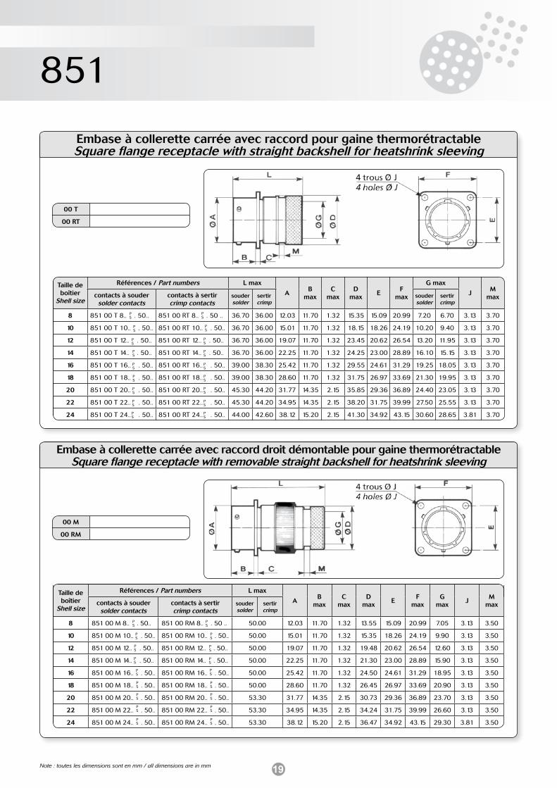
Embase à collerette carrée avec raccord pour gaine thermorétractableSquare flange receptacle with straight backshell for heatshrink sleeving
00 T
00 RT
PS
PS
PS
PS
PS
PS
PS
PS
PS
PS
PS
PS
PS
PS
PS
PS
PS
PS
Embase à collerette carrée avec raccord droit démontable pour gaine thermorétractableSquare flange receptacle with removable straight backshell for heatshrink sleeving
PS
PS
PS
PS
PS
PS
PS
PS
PS
Taille de boîtier
Shell size
Références / Part numbers L max
AB
maxC
maxD
maxE
Fmax
G max
JM
maxcontacts à soudersolder contacts
contacts à sertircrimp contacts
souder solder
sertircrimp
souder solder
sertircrimp
8 851 00 T 8.. . 50.. 851 00 RT 8.. . 50 .. 36.70 36.00 12.03 11.70 1.32 15.35 15.09 20.99 7.20 6.70 3.13 3.70
10 851 00 T 10.. . 50.. 851 00 RT 10.. . 50.. 36.70 36.00 15.01 11.70 1.32 18.15 18.26 24.19 10.20 9.40 3.13 3.70
12 851 00 T 12.. . 50.. 851 00 RT 12.. . 50.. 36.70 36.00 19.07 11.70 1.32 23.45 20.62 26.54 13.20 11.95 3.13 3.70
14 851 00 T 14.. . 50.. 851 00 RT 14.. . 50.. 36.70 36.00 22.25 11.70 1.32 24.25 23.00 28.89 16.10 15.15 3.13 3.70
16 851 00 T 16.. . 50.. 851 00 RT 16.. . 50.. 39.00 38.30 25.42 11.70 1.32 29.55 24.61 31.29 19.25 18.05 3.13 3.70
18 851 00 T 18.. . 50.. 851 00 RT 18.. . 50.. 39.00 38.30 28.60 11.70 1.32 31.75 26.97 33.69 21.30 19.95 3.13 3.70
20 851 00 T 20.. . 50.. 851 00 RT 20.. . 50.. 45.30 44.20 31.77 14.35 2.15 35.85 29.36 36.89 24.40 23.05 3.13 3.70
22 851 00 T 22.. . 50.. 851 00 RT 22.. . 50.. 45.30 44.20 34.95 14.35 2.15 38.20 31.75 39.99 27.50 25.55 3.13 3.70
24 851 00 T 24.. . 50.. 851 00 RT 24.. . 50.. 44.00 42.60 38.12 15.20 2.15 41.30 34.92 43.15 30.60 28.65 3.81 3.70
00 M
00 RM
Taille de boîtier
Shell size
Références / Part numbers L max
AB
maxC
maxD
maxE
Fmax
Gmax
JM
maxcontacts à soudersolder contacts
contacts à sertircrimp contacts
souder solder
sertircrimp
8 851 00 M 8.. . 50.. 851 00 RM 8.. . 50 .. 50.00 12.03 11.70 1.32 13.55 15.09 20.99 7.05 3.13 3.50
10 851 00 M 10.. . 50.. 851 00 RM 10.. . 50.. 50.00 15.01 11.70 1.32 15.35 18.26 24.19 9.90 3.13 3.50
12 851 00 M 12.. . 50.. 851 00 RM 12.. . 50.. 50.00 19.07 11.70 1.32 19.48 20.62 26.54 12.60 3.13 3.50
14 851 00 M 14.. . 50.. 851 00 RM 14.. . 50.. 50.00 22.25 11.70 1.32 21.30 23.00 28.89 15.90 3.13 3.50
16 851 00 M 16.. . 50.. 851 00 RM 16.. . 50.. 50.00 25.42 11.70 1.32 24.50 24.61 31.29 18.95 3.13 3.50
18 851 00 M 18.. . 50.. 851 00 RM 18.. . 50.. 50.00 28.60 11.70 1.32 26.45 26.97 33.69 20.90 3.13 3.50
20 851 00 M 20.. . 50.. 851 00 RM 20.. . 50.. 53.30 31.77 14.35 2.15 30.73 29.36 36.89 23.70 3.13 3.50
22 851 00 M 22.. . 50.. 851 00 RM 22.. . 50.. 53.30 34.95 14.35 2.15 34.24 31.75 39.99 26.60 3.13 3.50
24 851 00 M 24.. . 50.. 851 00 RM 24.. . 50.. 53.30 38.12 15.20 2.15 36.47 34.92 43.15 29.30 3.81 3.50
PS
PS
PS
PS
PS
PS
PS
PS
PS
Note : toutes les dimensions sont en mm / all dimensions are in mm
20
851
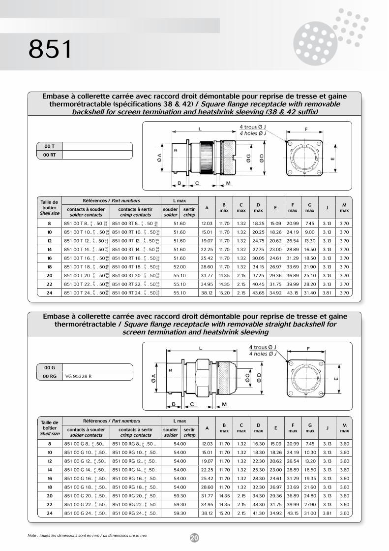
Embase à collerette carrée avec raccord droit démontable pour reprise de tresse et gaine thermorétractable (spécifications 38 & 42) / Square flange receptacle with removable
backshell for screen termination and heatshrink sleeving (38 & 42 suffix)
00 T
00 RT
Embase à collerette carrée avec raccord droit démontable pour reprise de tresse et gaine thermorétractable / Square flange receptacle with removable straight backshell for
screen termination and heatshrink sleeving
00 G
00 RG VG 95328 R
Taille de boîtier
Shell size
Références / Part numbers L max
AB
maxC
maxD
maxE
Fmax
Gmax
JM
max contacts à soudersolder contacts
contacts à sertircrimp contacts
souder solder
sertircrimp
8 851 00 G 8.. .50.. 851 00 RG 8.. .50 .. 54.00 12.03 11.70 1.32 16.30 15.09 20.99 7.45 3.13 3.60
10 851 00 G 10.. .50.. 851 00 RG 10.. .50.. 54.00 15.01 11.70 1.32 18.30 18.26 24.19 10.30 3.13 3.60
12 851 00 G 12.. .50.. 851 00 RG 12.. .50.. 54.00 19.07 11.70 1.32 22.30 20.62 26.54 13.20 3.13 3.60
14 851 00 G 14.. .50.. 851 00 RG 14.. .50.. 54.00 22.25 11.70 1.32 25.30 23.00 28.89 16.50 3.13 3.60
16 851 00 G 16.. .50.. 851 00 RG 16.. .50.. 54.00 25.42 11.70 1.32 28.30 24.61 31.29 19.35 3.13 3.60
18 851 00 G 18.. .50.. 851 00 RG 18.. .50.. 54.00 28.60 11.70 1.32 32.30 26.97 33.69 21.60 3.13 3.60
20 851 00 G 20.. .50.. 851 00 RG 20.. .50.. 59.30 31.77 14.35 2.15 34.30 29.36 36.89 24.80 3.13 3.60
22 851 00 G 22.. .50.. 851 00 RG 22.. .50.. 59.30 34.95 14.35 2.15 38.30 31.75 39.99 27.90 3.13 3.60
24 851 00 G 24.. .50.. 851 00 RG 24.. .50.. 59.30 38.12 15.20 2.15 41.30 34.92 43.15 31.00 3.81 3.60
PS
PS
PS
PS
PS
PS
PS
PS
PS
PS
PS
PS
PS
PS
PS
PS
PS
Taille de boîtier
Shell size
Références / Part numbers L max
AB
maxC
maxD
maxE
Fmax
Gmax
JM
maxcontacts à soudersolder contacts
contacts à sertircrimp contacts
souder solder
sertircrimp
8 851 00 T 8.. . 50 851 00 RT 8.. . 50 51.60 12.03 11.70 1.32 18.25 15.09 20.99 7.45 3.13 3.70
10 851 00 T 10.. . 50 851 00 RT 10.. . 50 51.60 15.01 11.70 1.32 20.25 18.26 24.19 9.00 3.13 3.70
12 851 00 T 12.. . 50 851 00 RT 12.. . 50 51.60 19.07 11.70 1.32 24.75 20.62 26.54 13.30 3.13 3.70
14 851 00 T 14.. . 50 851 00 RT 14.. . 50 51.60 22.25 11.70 1.32 27.75 23.00 28.89 16.50 3.13 3.70
16 851 00 T 16.. . 50 851 00 RT 16.. . 50 51.60 25.42 11.70 1.32 30.05 24.61 31.29 18.50 3.13 3.70
18 851 00 T 18.. . 50 851 00 RT 18.. . 50 52.00 28.60 11.70 1.32 34.15 26.97 33.69 21.90 3.13 3.70
20 851 00 T 20.. . 50 851 00 RT 20.. . 50 55.10 31.77 14.35 2.15 37.25 29.36 36.89 25.10 3.13 3.70
22 851 00 T 22.. . 50 851 00 RT 22.. . 50 55.10 34.95 14.35 2.15 40.45 31.75 39.99 28.20 3.13 3.70
24 851 00 T 24.. . 50 851 00 RT 24.. . 50 55.10 38.12 15.20 2.15 43.65 34.92 43.15 31.40 3.81 3.70
PS
PS
PS
PS
PS
PS
PS
PS
PS
PS
PS
PS
PS
PS
PS
PS
PS
PS
PS
3842
3842
3842
3842
3842
3842
3842
3842
3842
3842
3842
3842
3842
3842
3842
3842
3842
3842
Note : toutes les dimensions sont en mm / all dimensions are in mm
21
851
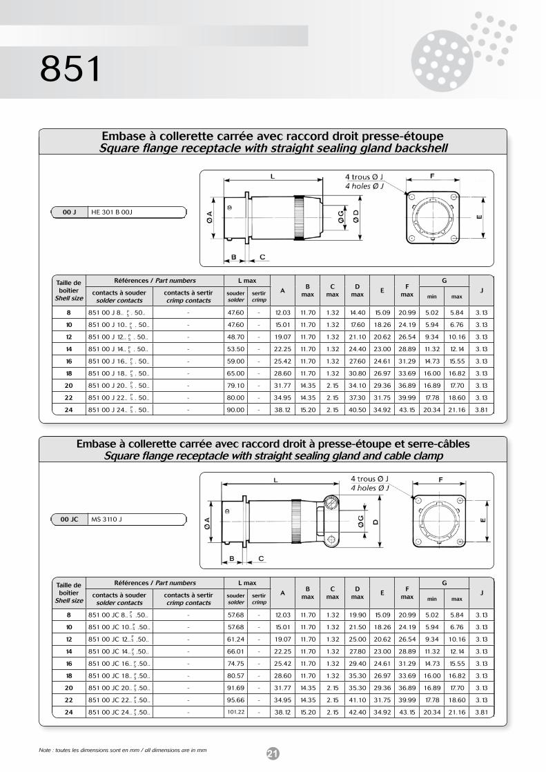
Embase à collerette carrée avec raccord droit presse-étoupeSquare flange receptacle with straight sealing gland backshell
00 J HE 301 B 00J
Embase à collerette carrée avec raccord droit à presse-étoupe et serre-câblesSquare flange receptacle with straight sealing gland and cable clamp
PS
PS
PS
PS
PS
PS
PS
PS
PS
Taille de boîtier
Shell size
Références / Part numbers L max
AB
maxC
maxD
maxE
Fmax
G
Jcontacts à soudersolder contacts
contacts à sertircrimp contacts
souder solder
sertircrimp min max
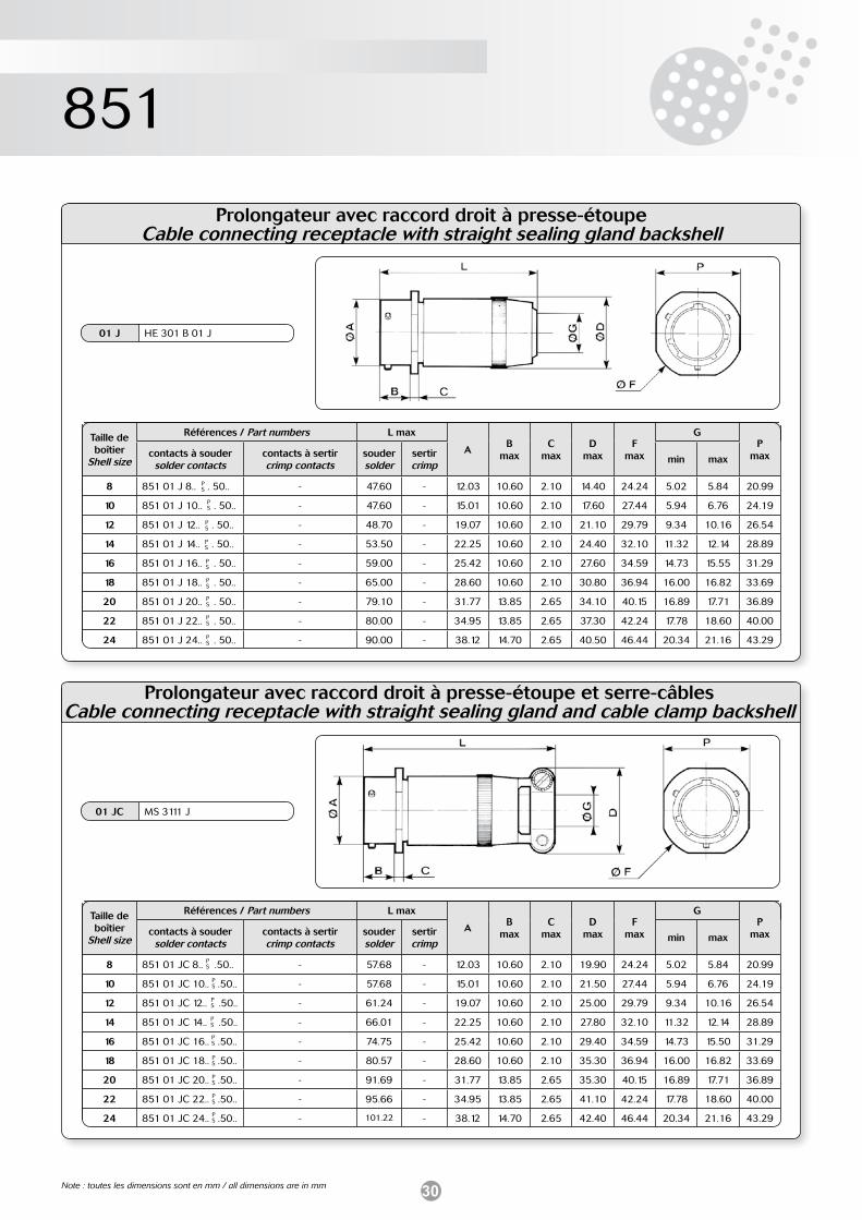
8 851 00 J 8.. . 50.. - 47.60 - 12.03 11.70 1.32 14.40 15.09 20.99 5.02 5.84 3.13
10 851 00 J 10.. . 50.. - 47.60 - 15.01 11.70 1.32 17.60 18.26 24.19 5.94 6.76 3.13
12 851 00 J 12.. . 50.. - 48.70 - 19.07 11.70 1.32 21.10 20.62 26.54 9.34 10.16 3.13
14 851 00 J 14.. . 50.. - 53.50 - 22.25 11.70 1.32 24.40 23.00 28.89 11.32 12.14 3.13
16 851 00 J 16.. . 50.. - 59.00 - 25.42 11.70 1.32 27.60 24.61 31.29 14.73 15.55 3.13
18 851 00 J 18.. . 50.. - 65.00 - 28.60 11.70 1.32 30.80 26.97 33.69 16.00 16.82 3.13
20 851 00 J 20.. . 50.. - 79.10 - 31.77 14.35 2.15 34.10 29.36 36.89 16.89 17.70 3.13
22 851 00 J 22.. . 50.. - 80.00 - 34.95 14.35 2.15 37.30 31.75 39.99 17.78 18.60 3.13
24 851 00 J 24.. . 50.. - 90.00 - 38.12 15.20 2.15 40.50 34.92 43.15 20.34 21.16 3.81
PS
PS
PS
PS
PS
PS
PS
PS
PS
00 JC MS 3110 J
Taille de boîtier
Shell size
Références / Part numbers L max
AB
maxC
maxD
maxE
Fmax
G
Jcontacts à soudersolder contacts
contacts à sertircrimp contacts
souder solder
sertircrimp min max
8 851 00 JC 8.. .50.. - 57.68 - 12.03 11.70 1.32 19.90 15.09 20.99 5.02 5.84 3.13
10 851 00 JC 10.. .50.. - 57.68 - 15.01 11.70 1.32 21.50 18.26 24.19 5.94 6.76 3.13
12 851 00 JC 12.. .50.. - 61.24 - 19.07 11.70 1.32 25.00 20.62 26.54 9.34 10.16 3.13
14 851 00 JC 14.. .50.. - 66.01 - 22.25 11.70 1.32 27.80 23.00 28.89 11.32 12.14 3.13
16 851 00 JC 16.. .50.. - 74.75 - 25.42 11.70 1.32 29.40 24.61 31.29 14.73 15.55 3.13
18 851 00 JC 18.. .50.. - 80.57 - 28.60 11.70 1.32 35.30 26.97 33.69 16.00 16.82 3.13
20 851 00 JC 20.. .50.. - 91.69 - 31.77 14.35 2.15 35.30 29.36 36.89 16.89 17.70 3.13
22 851 00 JC 22.. .50.. - 95.66 - 34.95 14.35 2.15 41.10 31.75 39.99 17.78 18.60 3.13
24 851 00 JC 24.. .50.. - 101.22 - 38.12 15.20 2.15 42.40 34.92 43.15 20.34 21.16 3.81
Note : toutes les dimensions sont en mm / all dimensions are in mm
22
851
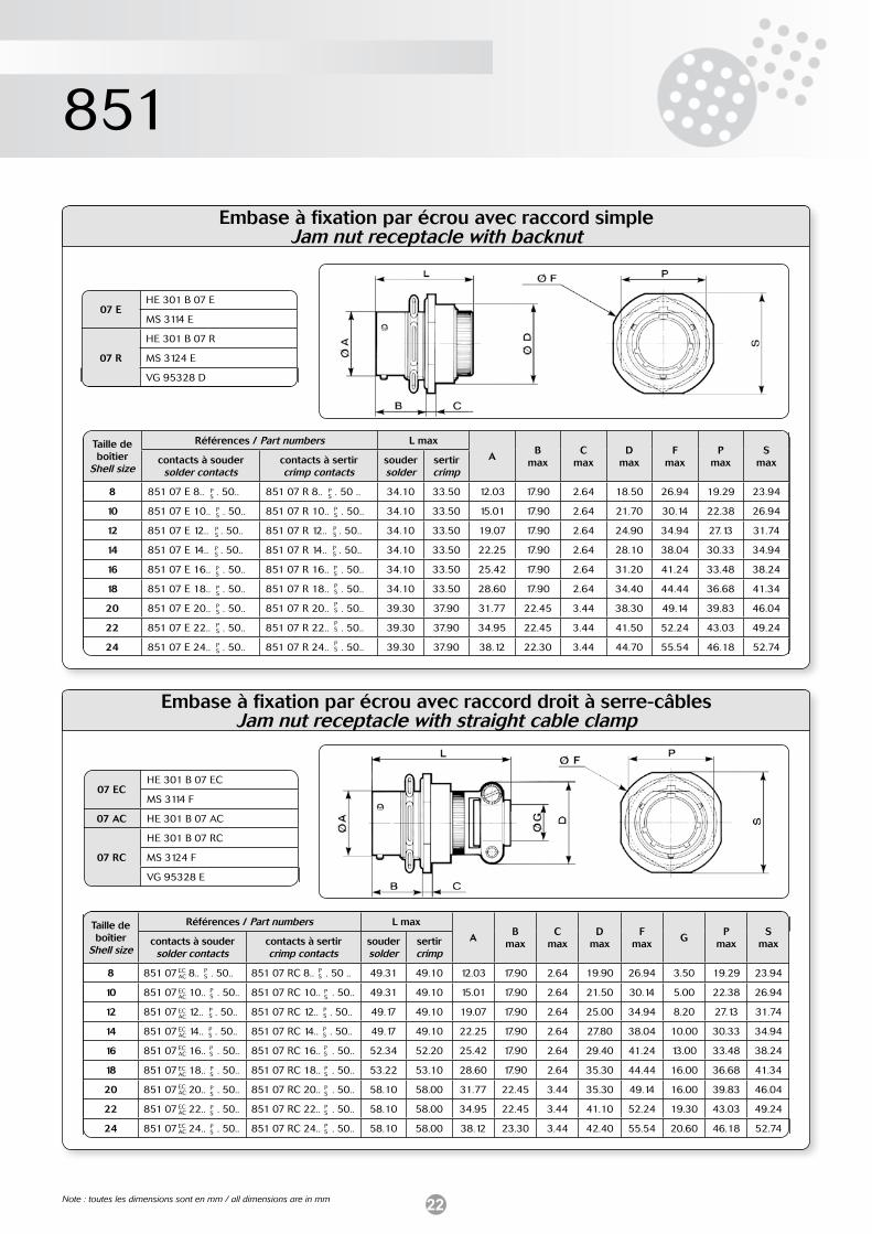
Embase à fixation par écrou avec raccord simpleJam nut receptacle with backnut
07 EHE 301 B 07 E
MS 3114 E
07 R
HE 301 B 07 R
MS 3124 E
VG 95328 D
Taille de boîtier
Shell size
Références / Part numbers L max
AB
maxC
maxD
maxF
maxP
maxS
maxcontacts à soudersolder contacts
contacts à sertircrimp contacts
souder solder
sertircrimp
8 851 07 E 8.. . 50.. 851 07 R 8.. . 50 .. 34.10 33.50 12.03 17.90 2.64 18.50 26.94 19.29 23.94
10 851 07 E 10.. . 50.. 851 07 R 10.. . 50.. 34.10 33.50 15.01 17.90 2.64 21.70 30.14 22.38 26.94
12 851 07 E 12.. . 50.. 851 07 R 12.. . 50.. 34.10 33.50 19.07 17.90 2.64 24.90 34.94 27.13 31.74
14 851 07 E 14.. . 50.. 851 07 R 14.. . 50.. 34.10 33.50 22.25 17.90 2.64 28.10 38.04 30.33 34.94
16 851 07 E 16.. . 50.. 851 07 R 16.. . 50.. 34.10 33.50 25.42 17.90 2.64 31.20 41.24 33.48 38.24
18 851 07 E 18.. . 50.. 851 07 R 18.. . 50.. 34.10 33.50 28.60 17.90 2.64 34.40 44.44 36.68 41.34
20 851 07 E 20.. . 50.. 851 07 R 20.. . 50.. 39.30 37.90 31.77 22.45 3.44 38.30 49.14 39.83 46.04
22 851 07 E 22.. . 50.. 851 07 R 22.. . 50.. 39.30 37.90 34.95 22.45 3.44 41.50 52.24 43.03 49.24
24 851 07 E 24.. . 50.. 851 07 R 24.. . 50.. 39.30 37.90 38.12 22.30 3.44 44.70 55.54 46.18 52.74
PS
PS
PS
PS
PS
PS
PS
PS
PS
PS
PS
PS
PS
PS
PS
PS
PS
PS
Taille de boîtier
Shell size
Références / Part numbers L max
AB
maxC
maxD
maxF
maxG
Pmax
Smaxcontacts à souder
solder contactscontacts à sertircrimp contacts
souder solder
sertircrimp
8 851 07 8.. . 50.. 851 07 RC 8.. . 50 .. 49.31 49.10 12.03 17.90 2.64 19.90 26.94 3.50 19.29 23.94
10 851 07 10.. . 50.. 851 07 RC 10.. . 50.. 49.31 49.10 15.01 17.90 2.64 21.50 30.14 5.00 22.38 26.94
12 851 07 12.. . 50.. 851 07 RC 12.. . 50.. 49.17 49.10 19.07 17.90 2.64 25.00 34.94 8.20 27.13 31.74
14 851 07 14.. . 50.. 851 07 RC 14.. . 50.. 49.17 49.10 22.25 17.90 2.64 27.80 38.04 10.00 30.33 34.94
16 851 07 16.. . 50.. 851 07 RC 16.. . 50.. 52.34 52.20 25.42 17.90 2.64 29.40 41.24 13.00 33.48 38.24
18 851 07 18.. . 50.. 851 07 RC 18.. . 50.. 53.22 53.10 28.60 17.90 2.64 35.30 44.44 16.00 36.68 41.34
20 851 07 20.. . 50.. 851 07 RC 20.. . 50.. 58.10 58.00 31.77 22.45 3.44 35.30 49.14 16.00 39.83 46.04
22 851 07 22.. . 50.. 851 07 RC 22.. . 50.. 58.10 58.00 34.95 22.45 3.44 41.10 52.24 19.30 43.03 49.24
24 851 07 24.. . 50.. 851 07 RC 24.. . 50.. 58.10 58.00 38.12 23.30 3.44 42.40 55.54 20.60 46.18 52.74
PS
PS
PS
PS
PS
PS
PS
PS
PS
PS
PS
PS
PS
PS
PS
PS
PS
PS
07 ECHE 301 B 07 EC
MS 3114 F
07 AC HE 301 B 07 AC
07 RC
HE 301 B 07 RC
MS 3124 F
VG 95328 E
ECAC
ECAC
ECAC
ECAC
ECAC
ECAC
ECAC
ECAC
ECAC
Note : toutes les dimensions sont en mm / all dimensions are in mm
Embase à fixation par écrou avec raccord droit à serre-câblesJam nut receptacle with straight cable clamp
23
851
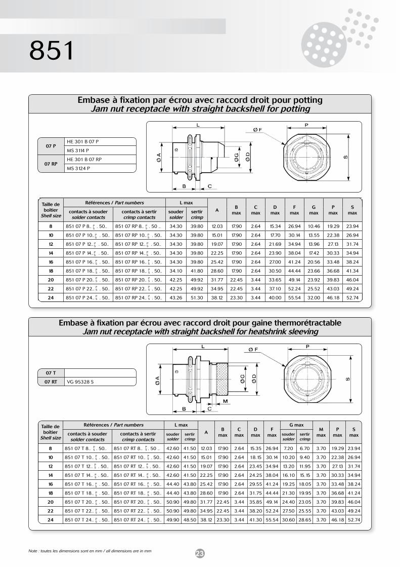
Embase à fixation par écrou avec raccord droit pour pottingJam nut receptacle with straight backshell for potting
Embase à fixation par écrou avec raccord droit pour gaine thermorétractableJam nut receptacle with straight backshell for heatshrink sleeving
PS
PS
PS
PS
PS
PS
PS
PS
PS
PS
PS
PS
PS
PS
PS
PS
PS
PS
07 T
07 RT VG 95328 S
07 PHE 301 B 07 P
MS 3114 P
07 RPHE 301 B 07 RP
MS 3124 P
Taille de boîtier
Shell size
Références / Part numbers L max
AB
maxC
maxD
maxF
maxG
maxP
maxS
maxcontacts à soudersolder contacts
contacts à sertircrimp contacts
souder solder
sertircrimp
8 851 07 P 8.. . 50.. 851 07 RP 8.. . 50 .. 34.30 39.80 12.03 17.90 2.64 15.34 26.94 10.46 19.29 23.94
10 851 07 P 10.. . 50.. 851 07 RP 10.. . 50.. 34.30 39.80 15.01 17.90 2.64 17.70 30.14 13.55 22.38 26.94
12 851 07 P 12.. . 50.. 851 07 RP 12.. . 50.. 34.30 39.80 19.07 17.90 2.64 21.69 34.94 13.96 27.13 31.74
14 851 07 P 14.. . 50.. 851 07 RP 14.. . 50.. 34.30 39.80 22.25 17.90 2.64 23.90 38.04 17.42 30.33 34.94
16 851 07 P 16.. . 50.. 851 07 RP 16.. . 50.. 34.30 39.80 25.42 17.90 2.64 27.00 41.24 20.56 33.48 38.24
18 851 07 P 18.. . 50.. 851 07 RP 18.. . 50.. 34.10 41.80 28.60 17.90 2.64 30.50 44.44 23.66 36.68 41.34
20 851 07 P 20.. . 50.. 851 07 RP 20.. . 50.. 42.25 49.92 31.77 22.45 3.44 33.65 49.14 23.92 39.83 46.04
22 851 07 P 22.. . 50.. 851 07 RP 22.. . 50.. 42.25 49.92 34.95 22.45 3.44 37.10 52.24 25.52 43.03 49.24
24 851 07 P 24.. . 50.. 851 07 RP 24.. . 50.. 43.26 51.30 38.12 23.30 3.44 40.00 55.54 32.00 46.18 52.74
PS
PS
PS
PS
PS
PS
PS
PS
PS
PS
PS
PS
PS
PS
PS
PS
PS
PS
Taille de boîtier
Shell size
Références / Part numbers L max
AB
maxC
maxD
maxF
max
G maxM
maxP
maxS
maxcontacts à soudersolder contacts
contacts à sertircrimp contacts
souder solder
sertircrimp
souder solder
sertircrimp
8 851 07 T 8.. . 50.. 851 07 RT 8.. . 50 .. 42.60 41.50 12.03 17.90 2.64 15.35 26.94 7.20 6.70 3.70 19.29 23.94
10 851 07 T 10.. . 50.. 851 07 RT 10.. . 50.. 42.60 41.50 15.01 17.90 2.64 18.15 30.14 10.20 9.40 3.70 22.38 26.94
12 851 07 T 12.. . 50.. 851 07 RT 12.. . 50.. 42.60 41.50 19.07 17.90 2.64 23.45 34.94 13.20 11.95 3.70 27.13 31.74
14 851 07 T 14.. . 50.. 851 07 RT 14.. . 50.. 42.60 41.50 22.25 17.90 2.64 24.25 38.04 16.10 15.15 3.70 30.33 34.94
16 851 07 T 16.. . 50.. 851 07 RT 16.. . 50.. 44.40 43.80 25.42 17.90 2.64 29.55 41.24 19.25 18.05 3.70 33.48 38.24
18 851 07 T 18.. . 50.. 851 07 RT 18.. . 50.. 44.40 43.80 28.60 17.90 2.64 31.75 44.44 21.30 19.95 3.70 36.68 41.24
20 851 07 T 20.. . 50.. 851 07 RT 20.. . 50.. 50.90 49.80 31.77 22.45 3.44 35.85 49.14 24.40 23.05 3.70 39.83 46.04
22 851 07 T 22.. . 50.. 851 07 RT 22.. . 50.. 50.90 49.80 34.95 22.45 3.44 38.20 52.24 27.50 25.55 3.70 43.03 49.24
24 851 07 T 24.. . 50.. 851 07 RT 24.. . 50.. 49.90 48.50 38.12 23.30 3.44 41.30 55.54 30.60 28.65 3.70 46.18 52.74
Note : toutes les dimensions sont en mm / all dimensions are in mm
24
851
07 T
07 RT
PS
PS
PS
PS
PS
PS
PS
PS
PS
PS
PS
PS
PS
PS
PS
PS
PS
PS
PS
PS
PS
PS
PS
PS
PS
PS
PS
PS
PS
PS
PS
PS
PS
PS
PS
PS
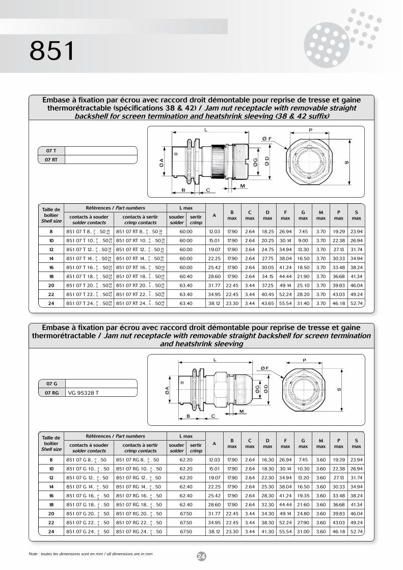
Embase à fixation par écrou avec raccord droit démontable pour reprise de tresse et gaine thermorétractable (spécifications 38 & 42) / Jam nut receptacle with removable straight
backshell for screen termination and heatshrink sleeving (38 & 42 suffix)
Taille de boîtier
Shell size
Références / Part numbers L max
AB
maxC
maxD
maxF
maxG
maxM
maxP
maxS
maxcontacts à soudersolder contacts
contacts à sertircrimp contacts
souder solder
sertircrimp
8 851 07 T 8.. . 50 851 07 RT 8.. . 50 60.00 12.03 17.90 2.64 18.25 26.94 7.45 3.70 19.29 23.94
10 851 07 T 10.. . 50 851 07 RT 10.. . 50 60.00 15.01 17.90 2.64 20.25 30.14 9.00 3.70 22.38 26.94
12 851 07 T 12.. . 50 851 07 RT 12.. . 50 60.00 19.07 17.90 2.64 24.75 34.94 13.30 3.70 27.13 31.74
14 851 07 T 14.. . 50 851 07 RT 14.. . 50 60.00 22.25 17.90 2.64 27.75 38.04 16.50 3.70 30.33 34.94
16 851 07 T 16.. . 50 851 07 RT 16.. . 50 60.00 25.42 17.90 2.64 30.05 41.24 18.50 3.70 33.48 38.24
18 851 07 T 18.. . 50 851 07 RT 18.. . 50 60.40 28.60 17.90 2.64 34.15 44.44 21.90 3.70 36.68 41.34
20 851 07 T 20.. . 50 851 07 RT 20.. . 50 63.40 31.77 22.45 3.44 37.25 49.14 25.10 3.70 39.83 46.04
22 851 07 T 22.. . 50 851 07 RT 22.. . 50 63.40 34.95 22.45 3.44 40.45 52.24 28.20 3.70 43.03 49.24
24 851 07 T 24.. . 50 851 07 RT 24.. . 50 63.40 38.12 23.30 3.44 43.65 55.54 31.40 3.70 46.18 52.74
Embase à fixation par écrou avec raccord droit démontable pour reprise de tresse et gaine thermorétractable / Jam nut receptacle with removable straight backshell for screen termination
and heatshrink sleeving
07 G
07 RG VG 95328 T
3842
3842
3842
3842
3842
3842
3842
3842
3842
3842
3842
3842
3842
3842
3842
3842
3842
3842
Taille de boîtier
Shell size
Références / Part numbers L max
AB
maxC
maxD
maxF
maxG
maxM
maxP
maxS
maxcontacts à soudersolder contacts
contacts à sertircrimp contacts
souder solder
sertircrimp
8 851 07 G 8.. . 50 851 07 RG 8.. . 50 62.20 12.03 17.90 2.64 16.30 26.94 7.45 3.60 19.29 23.94
10 851 07 G 10.. . 50 851 07 RG 10.. . 50 62.20 15.01 17.90 2.64 18.30 30.14 10.30 3.60 22.38 26.94
12 851 07 G 12.. . 50 851 07 RG 12.. . 50 62.20 19.07 17.90 2.64 22.30 34.94 13.20 3.60 27.13 31.74
14 851 07 G 14.. . 50 851 07 RG 14.. . 50 62.40 22.25 17.90 2.64 25.30 38.04 16.50 3.60 30.33 34.94
16 851 07 G 16.. . 50 851 07 RG 16.. . 50 62.40 25.42 17.90 2.64 28.30 41.24 19.35 3.60 33.48 38.24
18 851 07 G 18.. . 50 851 07 RG 18.. . 50 62.40 28.60 17.90 2.64 32.30 44.44 21.60 3.60 36.68 41.34
20 851 07 G 20.. . 50 851 07 RG 20.. . 50 67.50 31.77 22.45 3.44 34.30 49.14 24.80 3.60 39.83 46.04
22 851 07 G 22.. . 50 851 07 RG 22.. . 50 67.50 34.95 22.45 3.44 38.30 52.24 27.90 3.60 43.03 49.24
24 851 07 G 24.. . 50 851 07 RG 24.. . 50 67.50 38.12 23.30 3.44 41.30 55.54 31.00 3.60 46.18 52.74
Note : toutes les dimensions sont en mm / all dimensions are in mm
25
851
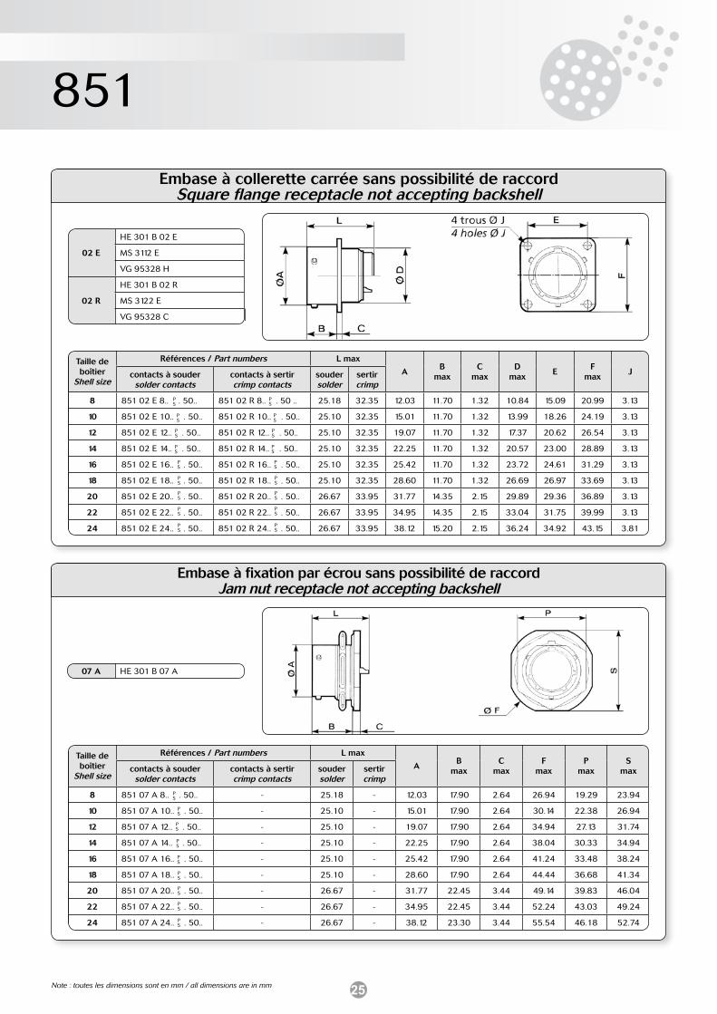
Embase à collerette carrée sans possibilité de raccordSquare flange receptacle not accepting backshell
Embase à fixation par écrou sans possibilité de raccordJam nut receptacle not accepting backshell
PS
PS
PS
PS
PS
PS
PS
PS
PS
PS
PS
PS
PS
PS
PS
PS
PS
PS
07 A HE 301 B 07 A
02 E
HE 301 B 02 E
MS 3112 E
VG 95328 H
02 R
HE 301 B 02 R
MS 3122 E
VG 95328 C
PS
PS
PS
PS
PS
PS
PS
PS
PS
Taille de boîtier
Shell size
Références / Part numbers L max
AB
maxC
maxD
maxE
Fmax
Jcontacts à soudersolder contacts
contacts à sertircrimp contacts
souder solder
sertircrimp
8 851 02 E 8.. . 50.. 851 02 R 8.. . 50 .. 25.18 32.35 12.03 11.70 1.32 10.84 15.09 20.99 3.13
10 851 02 E 10.. . 50.. 851 02 R 10.. . 50.. 25.10 32.35 15.01 11.70 1.32 13.99 18.26 24.19 3.13
12 851 02 E 12.. . 50.. 851 02 R 12.. . 50.. 25.10 32.35 19.07 11.70 1.32 17.37 20.62 26.54 3.13
14 851 02 E 14.. . 50.. 851 02 R 14.. . 50.. 25.10 32.35 22.25 11.70 1.32 20.57 23.00 28.89 3.13
16 851 02 E 16.. . 50.. 851 02 R 16.. . 50.. 25.10 32.35 25.42 11.70 1.32 23.72 24.61 31.29 3.13
18 851 02 E 18.. . 50.. 851 02 R 18.. . 50.. 25.10 32.35 28.60 11.70 1.32 26.69 26.97 33.69 3.13
20 851 02 E 20.. . 50.. 851 02 R 20.. . 50.. 26.67 33.95 31.77 14.35 2.15 29.89 29.36 36.89 3.13
22 851 02 E 22.. . 50.. 851 02 R 22.. . 50.. 26.67 33.95 34.95 14.35 2.15 33.04 31.75 39.99 3.13
24 851 02 E 24.. . 50.. 851 02 R 24.. . 50.. 26.67 33.95 38.12 15.20 2.15 36.24 34.92 43.15 3.81
Taille de boîtier
Shell size
Références / Part numbers L max
AB
maxC
maxF
maxP
maxS
maxcontacts à soudersolder contacts
contacts à sertircrimp contacts
souder solder
sertircrimp
8 851 07 A 8.. . 50.. - 25.18 - 12.03 17.90 2.64 26.94 19.29 23.94
10 851 07 A 10.. . 50.. - 25.10 - 15.01 17.90 2.64 30.14 22.38 26.94
12 851 07 A 12.. . 50.. - 25.10 - 19.07 17.90 2.64 34.94 27.13 31.74
14 851 07 A 14.. . 50.. - 25.10 - 22.25 17.90 2.64 38.04 30.33 34.94
16 851 07 A 16.. . 50.. - 25.10 - 25.42 17.90 2.64 41.24 33.48 38.24
18 851 07 A 18.. . 50.. - 25.10 - 28.60 17.90 2.64 44.44 36.68 41.34
20 851 07 A 20.. . 50.. - 26.67 - 31.77 22.45 3.44 49.14 39.83 46.04
22 851 07 A 22.. . 50.. - 26.67 - 34.95 22.45 3.44 52.24 43.03 49.24
24 851 07 A 24.. . 50.. - 26.67 - 38.12 23.30 3.44 55.54 46.18 52.74
Note : toutes les dimensions sont en mm / all dimensions are in mm
26
851
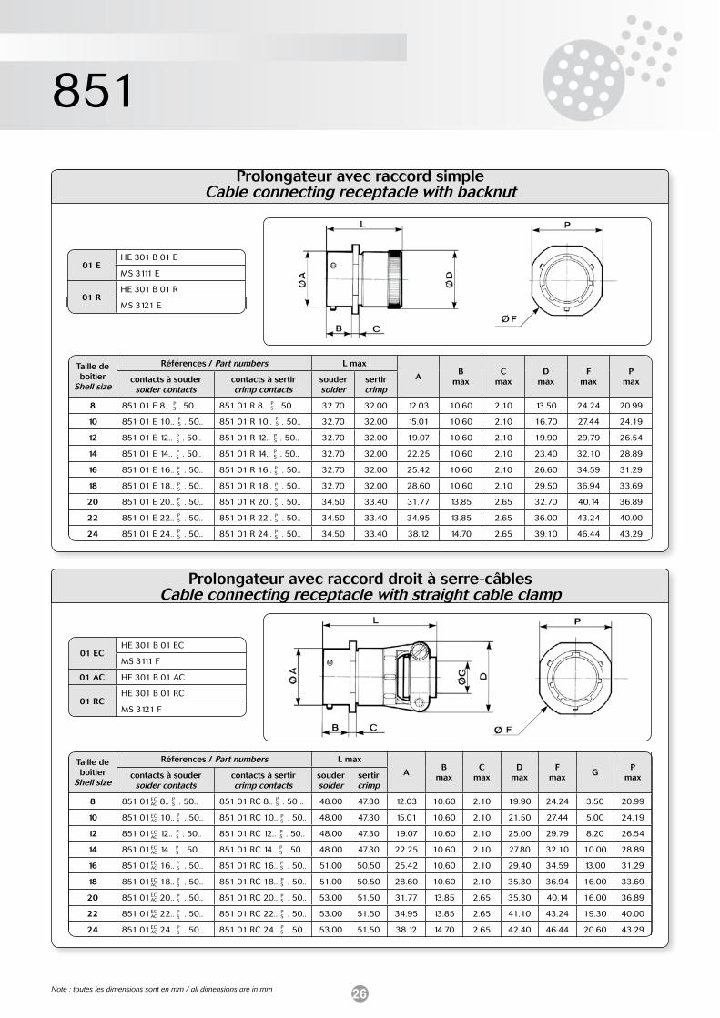
Prolongateur avec raccord simpleCable connecting receptacle with backnut
01 EHE 301 B 01 E
MS 3111 E
01 RHE 301 B 01 R
MS 3121 E
PS
PS
PS
PS
PS
PS
PS
PS
PS
PS
PS
PS
PS
PS
PS
PS
PS
PS
Prolongateur avec raccord droit à serre-câblesCable connecting receptacle with straight cable clamp
PS
PS
PS
PS
PS
PS
PS
PS
PS
PS
PS
PS
PS
PS
PS
PS
PS
PS
01 ECHE 301 B 01 EC
MS 3111 F
01 AC HE 301 B 01 AC
01 RCHE 301 B 01 RC
MS 3121 F
ECAC
ECAC
ECAC
ECAC
ECAC
ECAC
ECAC
ECAC
ECAC
Taille de boîtier
Shell size
Références / Part numbers L max
AB
maxC
maxD
maxF
maxP
maxcontacts à soudersolder contacts
contacts à sertircrimp contacts
souder solder
sertircrimp
8 851 01 E 8.. . 50.. 851 01 R 8.. . 50.. 32.70 32.00 12.03 10.60 2.10 13.50 24.24 20.99
10 851 01 E 10.. . 50.. 851 01 R 10.. . 50.. 32.70 32.00 15.01 10.60 2.10 16.70 27.44 24.19
12 851 01 E 12.. . 50.. 851 01 R 12.. . 50.. 32.70 32.00 19.07 10.60 2.10 19.90 29.79 26.54
14 851 01 E 14.. . 50.. 851 01 R 14.. . 50.. 32.70 32.00 22.25 10.60 2.10 23.40 32.10 28.89
16 851 01 E 16.. . 50.. 851 01 R 16.. . 50.. 32.70 32.00 25.42 10.60 2.10 26.60 34.59 31.29
18 851 01 E 18.. . 50.. 851 01 R 18.. . 50.. 32.70 32.00 28.60 10.60 2.10 29.50 36.94 33.69
20 851 01 E 20.. . 50.. 851 01 R 20.. . 50.. 34.50 33.40 31.77 13.85 2.65 32.70 40.14 36.89
22 851 01 E 22.. . 50.. 851 01 R 22.. . 50.. 34.50 33.40 34.95 13.85 2.65 36.00 43.24 40.00
24 851 01 E 24.. . 50.. 851 01 R 24.. . 50.. 34.50 33.40 38.12 14.70 2.65 39.10 46.44 43.29
Taille de boîtier
Shell size
Références / Part numbers L max
AB
maxC
maxD
maxF
maxG
Pmaxcontacts à souder
solder contactscontacts à sertircrimp contacts
souder solder
sertircrimp
8 851 01 8.. . 50.. 851 01 RC 8.. . 50 .. 48.00 47.30 12.03 10.60 2.10 19.90 24.24 3.50 20.99
10 851 01 10.. . 50.. 851 01 RC 10.. . 50.. 48.00 47.30 15.01 10.60 2.10 21.50 27.44 5.00 24.19
12 851 01 12.. . 50.. 851 01 RC 12.. . 50.. 48.00 47.30 19.07 10.60 2.10 25.00 29.79 8.20 26.54
14 851 01 14.. . 50.. 851 01 RC 14.. . 50.. 48.00 47.30 22.25 10.60 2.10 27.80 32.10 10.00 28.89
16 851 01 16.. . 50.. 851 01 RC 16.. . 50.. 51.00 50.50 25.42 10.60 2.10 29.40 34.59 13.00 31.29
18 851 01 18.. . 50.. 851 01 RC 18.. . 50.. 51.00 50.50 28.60 10.60 2.10 35.30 36.94 16.00 33.69
20 851 01 20.. . 50.. 851 01 RC 20.. . 50.. 53.00 51.50 31.77 13.85 2.65 35.30 40.14 16.00 36.89
22 851 01 22.. . 50.. 851 01 RC 22.. . 50.. 53.00 51.50 34.95 13.85 2.65 41.10 43.24 19.30 40.00
24 851 01 24.. . 50.. 851 01 RC 24.. . 50.. 53.00 51.50 38.12 14.70 2.65 42.40 46.44 20.60 43.29
Note : toutes les dimensions sont en mm / all dimensions are in mm
27
851
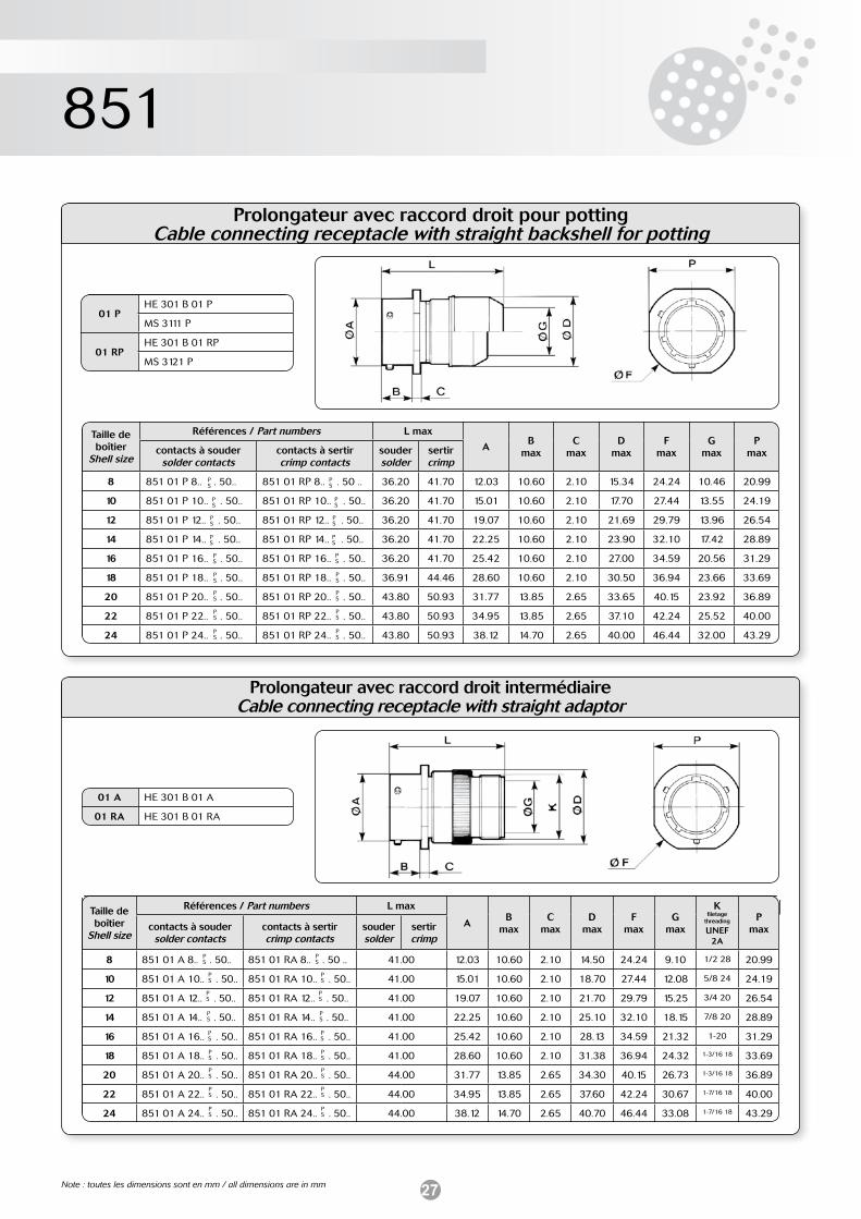
Prolongateur avec raccord droit pour pottingCable connecting receptacle with straight backshell for potting
Prolongateur avec raccord droit intermédiaireCable connecting receptacle with straight adaptor
PS
PS
PS
PS
PS
PS
PS
PS
PS
PS
PS
PS
PS
PS
PS
PS
PS
PS
01 A HE 301 B 01 A
01 RA HE 301 B 01 RA
01 PHE 301 B 01 P
MS 3111 P
01 RPHE 301 B 01 RP
MS 3121 P
PS
PS
PS
PS
PS
PS
PS
PS
PS
Taille de boîtier
Shell size
Références / Part numbers L max
AB
maxC
maxD
maxF
maxG
maxP
maxcontacts à soudersolder contacts
contacts à sertircrimp contacts
souder solder
sertircrimp
8 851 01 P 8.. . 50.. 851 01 RP 8.. . 50 .. 36.20 41.70 12.03 10.60 2.10 15.34 24.24 10.46 20.99
10 851 01 P 10.. . 50.. 851 01 RP 10.. . 50.. 36.20 41.70 15.01 10.60 2.10 17.70 27.44 13.55 24.19
12 851 01 P 12.. . 50.. 851 01 RP 12.. . 50.. 36.20 41.70 19.07 10.60 2.10 21.69 29.79 13.96 26.54
14 851 01 P 14.. . 50.. 851 01 RP 14.. . 50.. 36.20 41.70 22.25 10.60 2.10 23.90 32.10 17.42 28.89
16 851 01 P 16.. . 50.. 851 01 RP 16.. . 50.. 36.20 41.70 25.42 10.60 2.10 27.00 34.59 20.56 31.29
18 851 01 P 18.. . 50.. 851 01 RP 18.. . 50.. 36.91 44.46 28.60 10.60 2.10 30.50 36.94 23.66 33.69
20 851 01 P 20.. . 50.. 851 01 RP 20.. . 50.. 43.80 50.93 31.77 13.85 2.65 33.65 40.15 23.92 36.89
22 851 01 P 22.. . 50.. 851 01 RP 22.. . 50.. 43.80 50.93 34.95 13.85 2.65 37.10 42.24 25.52 40.00
24 851 01 P 24.. . 50.. 851 01 RP 24.. . 50.. 43.80 50.93 38.12 14.70 2.65 40.00 46.44 32.00 43.29
Taille de boîtier
Shell size
Références / Part numbers L max
AB
maxC
maxD
maxF
maxG
max
Kfiletage
threading
UNEF 2A
Pmaxcontacts à souder
solder contactscontacts à sertircrimp contacts
souder solder
sertircrimp
8 851 01 A 8.. . 50.. 851 01 RA 8.. . 50 .. 41.00 12.03 10.60 2.10 14.50 24.24 9.10 1/2 28 20.99
10 851 01 A 10.. . 50.. 851 01 RA 10.. . 50.. 41.00 15.01 10.60 2.10 18.70 27.44 12.08 5/8 24 24.19
12 851 01 A 12.. . 50.. 851 01 RA 12.. . 50.. 41.00 19.07 10.60 2.10 21.70 29.79 15.25 3/4 20 26.54
14 851 01 A 14.. . 50.. 851 01 RA 14.. . 50.. 41.00 22.25 10.60 2.10 25.10 32.10 18.15 7/8 20 28.89
16 851 01 A 16.. . 50.. 851 01 RA 16.. . 50.. 41.00 25.42 10.60 2.10 28.13 34.59 21.32 1-20 31.29
18 851 01 A 18.. . 50.. 851 01 RA 18.. . 50.. 41.00 28.60 10.60 2.10 31.38 36.94 24.32 1-3/16 18 33.69
20 851 01 A 20.. . 50.. 851 01 RA 20.. . 50.. 44.00 31.77 13.85 2.65 34.30 40.15 26.73 1-3/16 18 36.89
22 851 01 A 22.. . 50.. 851 01 RA 22.. . 50.. 44.00 34.95 13.85 2.65 37.60 42.24 30.67 1-7/16 18 40.00
24 851 01 A 24.. . 50.. 851 01 RA 24.. . 50.. 44.00 38.12 14.70 2.65 40.70 46.44 33.08 1-7/16 18 43.29
PS
PS
PS
PS
PS
PS
PS
PS
PS
Note : toutes les dimensions sont en mm / all dimensions are in mm
28
851
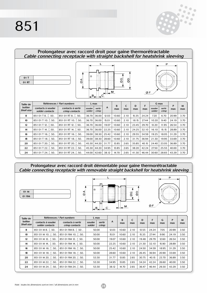
Prolongateur avec raccord droit pour gaine thermorétractableCable connecting receptacle with straight backshell for heatshrink sleeving
01 T
01 RT
PS
PS
PS
PS
PS
PS
PS
PS
PS
PS
PS
PS
PS
PS
PS
PS
PS
PS
Prolongateur avec raccord droit démontable pour gaine thermorétractableCable connecting receptacle with removable straight backshell for heatshrink sleeving
PS
PS
PS
PS
PS
PS
PS
PS
PS
PS
PS
PS
PS
PS
PS
PS
PS
PS
Taille de boîtier
Shell size
Références / Part numbers L max
AB
maxC
maxD
maxF
max
G maxP
maxM
maxcontacts à soudersolder contacts
contacts à sertircrimp contacts
souder solder
sertircrimp
soudersolder
sertircrimp
8 851 01 T 8.. .50.. 851 01 RT 8.. .50.. 36.70 36.00 12.03 10.60 2.10 15.35 24.24 7.20 6.70 20.99 3.70
10 851 01 T 10.. .50.. 851 01 RT 10.. .50.. 36.70 36.00 15.01 10.60 2.10 18.15 27.44 10.20 9.40 24.19 3.70
12 851 01 T 12.. .50.. 851 01 RT 12.. .50.. 36.70 36.00 19.07 10.60 2.10 23.45 29.70 13.20 11.95 26.54 3.70
14 851 01 T 14.. .50.. 851 01 RT 14.. .50.. 36.70 36.00 22.25 10.60 2.10 24.25 32.10 16.10 15.15 28.89 3.70
16 851 01 T 16.. .50.. 851 01 RT 16.. .50.. 39.00 38.30 25.42 10.60 2.10 29.55 34.59 19.25 18.05 31.29 3.70
18 851 01 T 18.. .50.. 851 01 RT 18.. .50.. 39.00 38.30 28.60 10.60 2.10 31.75 36.94 21.30 19.95 33.69 3.70
20 851 01 T 20.. .50.. 851 01 RT 20.. .50.. 45.30 44.20 31.77 13.85 2.65 35.85 40.15 24.40 23.05 36.89 3.70
22 851 01 T 22.. .50.. 851 01 RT 22.. .50.. 45.30 44.20 34.95 13.85 2.65 38.20 42.24 27.50 25.55 40.00 3.70
24 851 01 T 24.. .50.. 851 01 RT 24.. .50.. 44.00 42.60 38.12 14.70 2.65 41.30 46.44 30.60 28.65 43.29 3.70
01 M
01 RM
Taille de boîtier
Shell size
Références / Part numbers L max
AB
maxC
maxD
maxF
maxG
maxP
maxM
maxcontacts à soudersolder contacts
contacts à sertircrimp contacts
souder solder
sertircrimp
8 851 01 M 8.. .50.. 851 01 RM 8.. .50 .. 50.00 12.03 10.60 2.10 13.55 24.24 7.05 20.99 3.50
10 851 01 M 10.. .50.. 851 01 RM 10.. .50.. 50.00 15.01 10.60 2.10 15.35 27.44 9.90 24.19 3.50
12 851 01 M 12.. .50.. 851 01 RM 12.. .50.. 50.00 19.07 10.60 2.10 19.48 29.79 12.60 26.54 3.50
14 851 01 M 14.. .50.. 851 01 RM 14.. .50.. 50.00 22.25 10.60 2.10 21.30 32.10 15.90 28.89 3.50
16 851 01 M 16.. .50.. 851 01 RM 16.. .50.. 50.00 25.42 10.60 2.10 24.50 34.59 18.95 31.29 3.50
18 851 01 M 18.. .50.. 851 01 RM 18.. .50.. 50.00 28.60 10.60 2.10 26.45 36.94 20.90 33.69 3.50
20 851 01 M 20.. .50.. 851 01 RM 20.. .50.. 53.30 31.77 13.85 2.65 30.75 40.15 23.70 36.89 3.50
22 851 01 M 22.. .50.. 851 01 RM 22.. .50.. 53.30 34.95 13.85 2.65 34.24 42.24 26.60 40.00 3.50
24 851 01 M 24.. .50.. 851 01 RM 24.. .50.. 53.30 38.12 14.70 2.65 36.47 46.44 29.30 43.29 3.50
Note : toutes les dimensions sont en mm / all dimensions are in mm
29
851
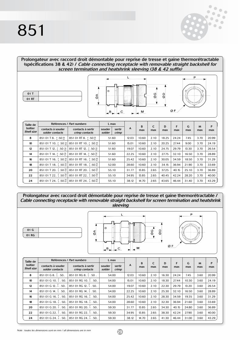
Prolongateur avec raccord droit démontable pour reprise de tresse et gaine thermorétractable / Cable connecting receptacle with removable straight backshell for screen termination and heatshrink
sleeving
PS
PS
PS
PS
PS
PS
PS
PS
PS
PS
PS
PS
PS
PS
PS
PS
PS
PS
01 G
01 RG
01 T
01 RT
PS
PS
PS
PS
PS
PS
PS
PS
PS
Taille de boîtier
Shell size
Références / Part numbers L max
AB
maxC
maxD
maxF
maxG
maxM
maxP
maxcontacts à soudersolder contacts
contacts à sertircrimp contacts
souder solder
sertircrimp
8 851 01 G 8.. . 50.. 851 01 RG 8.. . 50 .. 54.00 12.03 10.60 2.10 16.30 24.24 7.45 3.60 20.99
10 851 01 G 10.. . 50.. 851 01 RG 10.. . 50.. 54.00 15.01 10.60 2.10 18.30 27.44 10.30 3.60 24.19
12 851 01 G 12.. . 50.. 851 01 RG 12.. . 50.. 54.00 19.07 10.60 2.10 22.30 29.79 13.20 3.60 26.54
14 851 01 G 14.. . 50.. 851 01 RG 14.. . 50.. 54.00 22.25 10.60 2.10 25.30 32.10 16.50 3.60 28.89
16 851 01 G 16.. . 50.. 851 01 RG 16.. . 50.. 54.00 25.42 10.60 2.10 28.30 34.59 19.35 3.60 31.29
18 851 01 G 18.. . 50.. 851 01 RG 18.. . 50.. 54.00 28.60 10.60 2.10 32.30 36.94 21.60 3.60 33.69
20 851 01 G 20.. . 50.. 851 01 RG 20.. . 50.. 59.30 31.77 13.85 2.65 34.30 40.15 24.80 3.60 36.89
22 851 01 G 22.. . 50.. 851 01 RG 22.. . 50.. 59.30 34.95 13.85 2.65 38.30 42.24 27.90 3.60 40.00
24 851 01 G 24.. . 50.. 851 01 RG 24.. . 50.. 59.30 38.12 14.70 2.65 41.30 46.44 31.00 3.60 43.29
PS
PS
PS
PS
PS
PS
PS
PS
PS
Prolongateur avec raccord droit démontable pour reprise de tresse et gaine thermorétractable (spécifications 38 & 42) / Cable connecting receptacle with removable straight backshell for
screen termination and heatshrink sleeving (38 & 42 suffix)
Taille de boîtier
Shell size
Références / Part numbers L max
AB
maxC
maxD
maxF
maxG
maxM
maxP
maxcontacts à soudersolder contacts
contacts à sertircrimp contacts
souder solder
sertircrimp
8 851 01 T 8.. .50 851 01 RT 8.. .50 51.60 12.03 10.60 2.10 18.25 24.24 7.45 3.70 20.99
10 851 01 T 10.. .50 851 01 RT 10.. .50 51.60 15.01 10.60 2.10 20.25 27.44 9.00 3.70 24.19
12 851 01 T 12.. .50 851 01 RT 12.. .50 51.60 19.07 10.60 2.10 24.75 29.79 13.30 3.70 26.54
14 851 01 T 14.. .50 851 01 RT 14.. .50 51.60 22.25 10.60 2.10 27.75 32.10 16.50 3.70 28.89
16 851 01 T 16.. .50 851 01 RT 16.. .50 51.60 25.42 10.60 2.10 30.05 34.59 18.50 3.70 31.29
18 851 01 T 18.. .50 851 01 RT 18.. .50 52.00 28.60 10.60 2.10 34.15 36.94 21.90 3.70 33.69
20 851 01 T 20.. .50 851 01 RT 20.. .50 55.10 31.77 13.85 2.65 37.25 40.15 25.10 3.70 36.89
22 851 01 T 22.. .50 851 01 RT 22.. .50 55.10 34.95 13.85 2.65 40.45 42.24 28.20 3.70 40.00
24 851 01 T 24.. .50 851 01 RT 24.. .50 55.10 38.12 14.70 2.65 43.65 46.44 31.40 3.70 43.29
3842
3842
3842
3842
3842
3842
3842
3842
3842
3842
3842
3842
3842
3842
3842
3842
3842
3842
Note : toutes les dimensions sont en mm / all dimensions are in mm
30
851
Prolongateur avec raccord droit à presse-étoupeCable connecting receptacle with straight sealing gland backshell
01 J HE 301 B 01 J
PS
PS
PS
PS
PS
PS
PS
PS
PS
Prolongateur avec raccord droit à presse-étoupe et serre-câblesCable connecting receptacle with straight sealing gland and cable clamp backshell
PS
PS
PS
PS
PS
PS
PS
PS
PS
Taille de boîtier
Shell size
Références / Part numbers L max
AB
maxC
maxD
maxF
max
GP
maxcontacts à soudersolder contacts
contacts à sertircrimp contacts
souder solder
sertircrimp min max
8 851 01 J 8.. . 50.. - 47.60 - 12.03 10.60 2.10 14.40 24.24 5.02 5.84 20.99
10 851 01 J 10.. . 50.. - 47.60 - 15.01 10.60 2.10 17.60 27.44 5.94 6.76 24.19
12 851 01 J 12.. . 50.. - 48.70 - 19.07 10.60 2.10 21.10 29.79 9.34 10.16 26.54
14 851 01 J 14.. . 50.. - 53.50 - 22.25 10.60 2.10 24.40 32.10 11.32 12.14 28.89
16 851 01 J 16.. . 50.. - 59.00 - 25.42 10.60 2.10 27.60 34.59 14.73 15.55 31.29
18 851 01 J 18.. . 50.. - 65.00 - 28.60 10.60 2.10 30.80 36.94 16.00 16.82 33.69
20 851 01 J 20.. . 50.. - 79.10 - 31.77 13.85 2.65 34.10 40.15 16.89 17.71 36.89
22 851 01 J 22.. . 50.. - 80.00 - 34.95 13.85 2.65 37.30 42.24 17.78 18.60 40.00
24 851 01 J 24.. . 50.. - 90.00 - 38.12 14.70 2.65 40.50 46.44 20.34 21.16 43.29
01 JC MS 3111 J
Taille de boîtier
Shell size
Références / Part numbers L max
AB
maxC
maxD
maxF
max
GP
maxcontacts à soudersolder contacts
contacts à sertircrimp contacts
souder solder
sertircrimp min max
8 851 01 JC 8.. .50.. - 57.68 - 12.03 10.60 2.10 19.90 24.24 5.02 5.84 20.99
10 851 01 JC 10.. .50.. - 57.68 - 15.01 10.60 2.10 21.50 27.44 5.94 6.76 24.19
12 851 01 JC 12.. .50.. - 61.24 - 19.07 10.60 2.10 25.00 29.79 9.34 10.16 26.54
14 851 01 JC 14.. .50.. - 66.01 - 22.25 10.60 2.10 27.80 32.10 11.32 12.14 28.89
16 851 01 JC 16.. .50.. - 74.75 - 25.42 10.60 2.10 29.40 34.59 14.73 15.50 31.29
18 851 01 JC 18.. .50.. - 80.57 - 28.60 10.60 2.10 35.30 36.94 16.00 16.82 33.69
20 851 01 JC 20.. .50.. - 91.69 - 31.77 13.85 2.65 35.30 40.15 16.89 17.71 36.89
22 851 01 JC 22.. .50.. - 95.66 - 34.95 13.85 2.65 41.10 42.24 17.78 18.60 40.00
24 851 01 JC 24.. .50.. - 101.22 - 38.12 14.70 2.65 42.40 46.44 20.34 21.16 43.29
Note : toutes les dimensions sont en mm / all dimensions are in mm
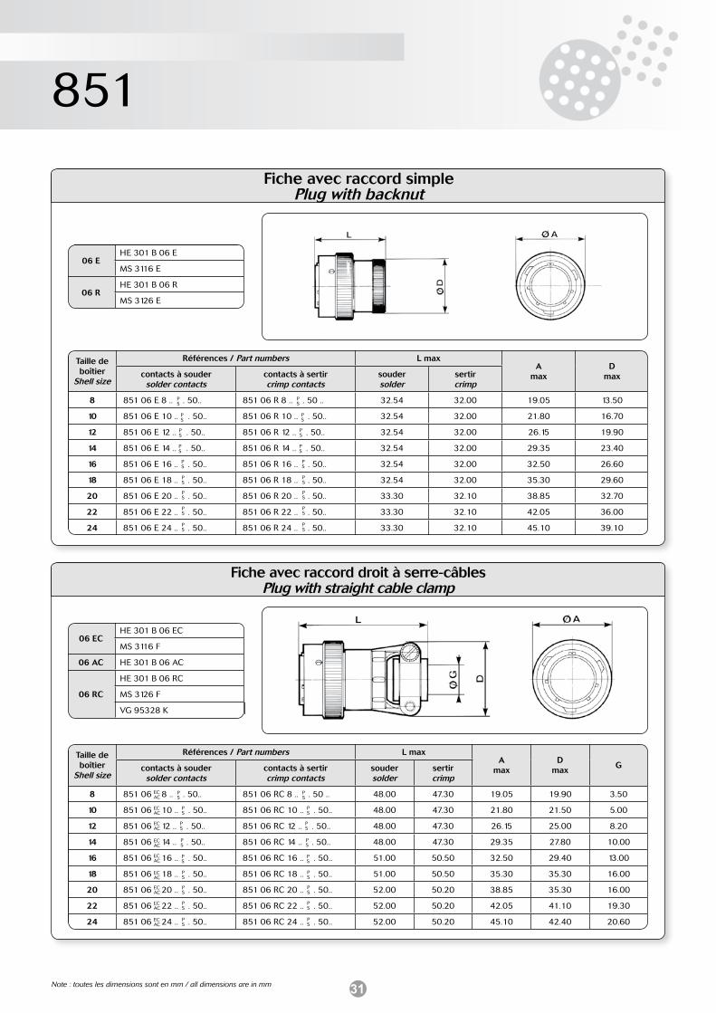
31
851
Fiche avec raccord simplePlug with backnut
Fiche avec raccord droit à serre-câblesPlug with straight cable clamp
PS
PS
PS
PS
PS
PS
PS
PS
PS
PS
PS
PS
PS
PS
PS
PS
PS
PS
06 ECHE 301 B 06 EC
MS 3116 F
06 AC HE 301 B 06 AC
06 RC
HE 301 B 06 RC
MS 3126 F
VG 95328 K
06 EHE 301 B 06 E
MS 3116 E
06 RHE 301 B 06 R
MS 3126 E
PS
PS
PS
PS
PS
PS
PS
PS
PS
Taille de boîtier
Shell size
Références / Part numbers L maxA
maxD
maxcontacts à soudersolder contacts
contacts à sertircrimp contacts
souder solder
sertircrimp
8 851 06 E 8 .. . 50.. 851 06 R 8 .. . 50 .. 32.54 32.00 19.05 13.50
10 851 06 E 10 .. . 50.. 851 06 R 10 .. . 50.. 32.54 32.00 21.80 16.70
12 851 06 E 12 .. . 50.. 851 06 R 12 .. . 50.. 32.54 32.00 26.15 19.90
14 851 06 E 14 .. . 50.. 851 06 R 14 .. . 50.. 32.54 32.00 29.35 23.40
16 851 06 E 16 .. . 50.. 851 06 R 16 .. . 50.. 32.54 32.00 32.50 26.60
18 851 06 E 18 .. . 50.. 851 06 R 18 .. . 50.. 32.54 32.00 35.30 29.60
20 851 06 E 20 .. . 50.. 851 06 R 20 .. . 50.. 33.30 32.10 38.85 32.70
22 851 06 E 22 .. . 50.. 851 06 R 22 .. . 50.. 33.30 32.10 42.05 36.00
24 851 06 E 24 .. . 50.. 851 06 R 24 .. . 50.. 33.30 32.10 45.10 39.10
PS
PS
PS
PS
PS
PS
PS
PS
PS
Taille de boîtier
Shell size
Références / Part numbers L maxA
maxD
maxGcontacts à souder
solder contactscontacts à sertircrimp contacts
souder solder
sertircrimp
8 851 06 8 .. . 50.. 851 06 RC 8 .. . 50 .. 48.00 47.30 19.05 19.90 3.50
10 851 06 10 .. . 50.. 851 06 RC 10 .. . 50.. 48.00 47.30 21.80 21.50 5.00
12 851 06 12 .. . 50.. 851 06 RC 12 .. . 50.. 48.00 47.30 26.15 25.00 8.20
14 851 06 14 .. . 50.. 851 06 RC 14 .. . 50.. 48.00 47.30 29.35 27.80 10.00
16 851 06 16 .. . 50.. 851 06 RC 16 .. . 50.. 51.00 50.50 32.50 29.40 13.00
18 851 06 18 .. . 50.. 851 06 RC 18 .. . 50.. 51.00 50.50 35.30 35.30 16.00
20 851 06 20 .. . 50.. 851 06 RC 20 .. . 50.. 52.00 50.20 38.85 35.30 16.00
22 851 06 22 .. . 50.. 851 06 RC 22 .. . 50.. 52.00 50.20 42.05 41.10 19.30
24 851 06 24 .. . 50.. 851 06 RC 24 .. . 50.. 52.00 50.20 45.10 42.40 20.60
ECAC
ECAC
ECAC
ECAC
ECAC
ECAC
ECAC
ECAC
ECAC
Note : toutes les dimensions sont en mm / all dimensions are in mm
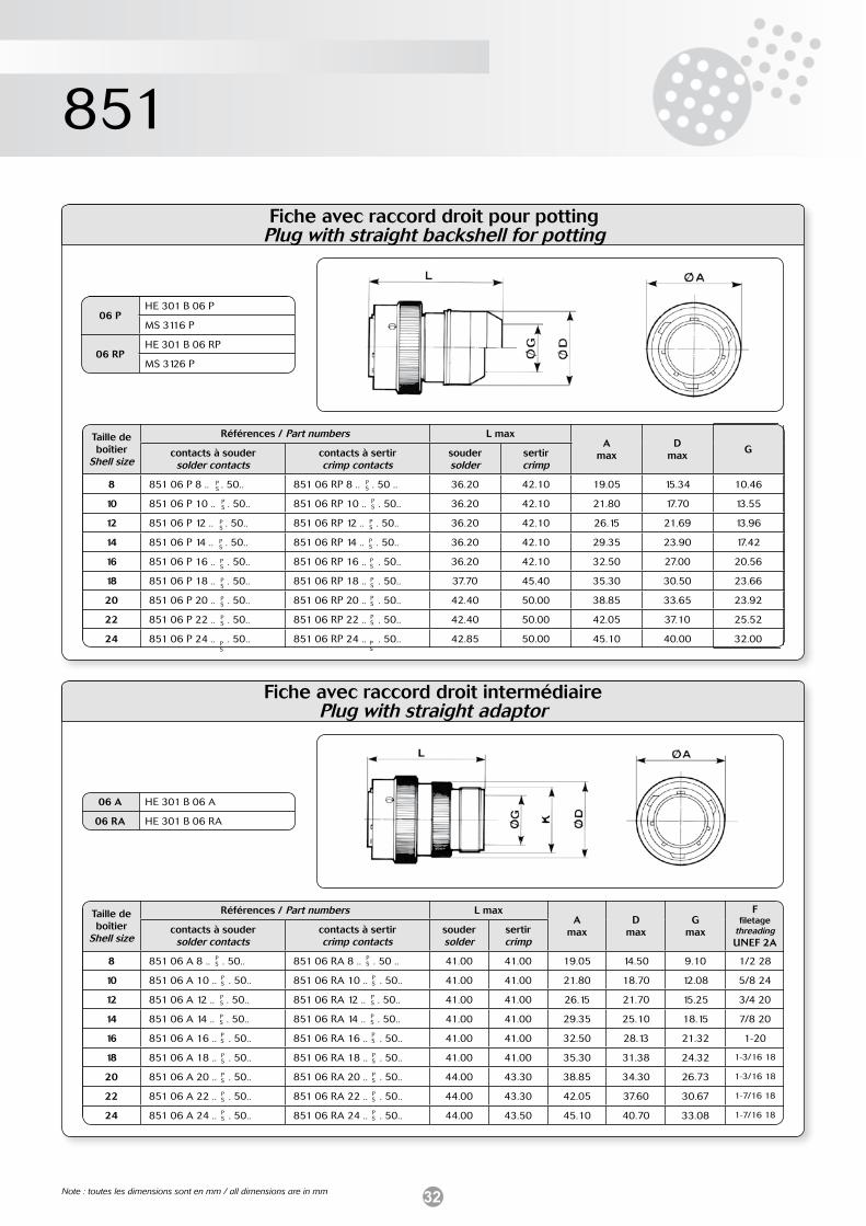
32
851
Fiche avec raccord droit pour pottingPlug with straight backshell for potting
PS
PS
PS
PS
PS
PS
PS
PS
PS
Fiche avec raccord droit intermédiairePlug with straight adaptor
PS
PS
PS
PS
PS
PS
PS
PS
PS
06 PHE 301 B 06 P
MS 3116 P
06 RPHE 301 B 06 RP
MS 3126 P
Taille de boîtier
Shell size
Références / Part numbers L maxA
maxD
maxGcontacts à souder
solder contactscontacts à sertircrimp contacts
souder solder
sertircrimp
8 851 06 P 8 .. . 50.. 851 06 RP 8 .. . 50 .. 36.20 42.10 19.05 15.34 10.46
10 851 06 P 10 .. . 50.. 851 06 RP 10 .. . 50.. 36.20 42.10 21.80 17.70 13.55
12 851 06 P 12 .. . 50.. 851 06 RP 12 .. . 50.. 36.20 42.10 26.15 21.69 13.96
14 851 06 P 14 .. . 50.. 851 06 RP 14 .. . 50.. 36.20 42.10 29.35 23.90 17.42
16 851 06 P 16 .. . 50.. 851 06 RP 16 .. . 50.. 36.20 42.10 32.50 27.00 20.56
18 851 06 P 18 .. . 50.. 851 06 RP 18 .. . 50.. 37.70 45.40 35.30 30.50 23.66
20 851 06 P 20 .. . 50.. 851 06 RP 20 .. . 50.. 42.40 50.00 38.85 33.65 23.92
22 851 06 P 22 .. . 50.. 851 06 RP 22 .. . 50.. 42.40 50.00 42.05 37.10 25.52
24 851 06 P 24 .. . 50.. 851 06 RP 24 .. . 50.. 42.85 50.00 45.10 40.00 32.00
PS
PS
PS
PS
PS
PS
PS
PS
PS
06 A HE 301 B 06 A
06 RA HE 301 B 06 RA
Taille de boîtier
Shell size
Références / Part numbers L maxA
maxD
maxG
max
Ffiletage
threadingUNEF 2A
contacts à soudersolder contacts
contacts à sertircrimp contacts
souder solder
sertircrimp
8 851 06 A 8 .. . 50.. 851 06 RA 8 .. . 50 .. 41.00 41.00 19.05 14.50 9.10 1/2 28
10 851 06 A 10 .. . 50.. 851 06 RA 10 .. . 50.. 41.00 41.00 21.80 18.70 12.08 5/8 24
12 851 06 A 12 .. . 50.. 851 06 RA 12 .. . 50.. 41.00 41.00 26.15 21.70 15.25 3/4 20
14 851 06 A 14 .. . 50.. 851 06 RA 14 .. . 50.. 41.00 41.00 29.35 25.10 18.15 7/8 20
16 851 06 A 16 .. . 50.. 851 06 RA 16 .. . 50.. 41.00 41.00 32.50 28.13 21.32 1-20
18 851 06 A 18 .. . 50.. 851 06 RA 18 .. . 50.. 41.00 41.00 35.30 31.38 24.32 1-3/16 18
20 851 06 A 20 .. . 50.. 851 06 RA 20 .. . 50.. 44.00 43.30 38.85 34.30 26.73 1-3/16 18
22 851 06 A 22 .. . 50.. 851 06 RA 22 .. . 50.. 44.00 43.30 42.05 37.60 30.67 1-7/16 18
24 851 06 A 24 .. . 50.. 851 06 RA 24 .. . 50.. 44.00 43.50 45.10 40.70 33.08 1-7/16 18
PS
PS
PS
PS
PS
PS
PS
PS
PS
Note : toutes les dimensions sont en mm / all dimensions are in mm
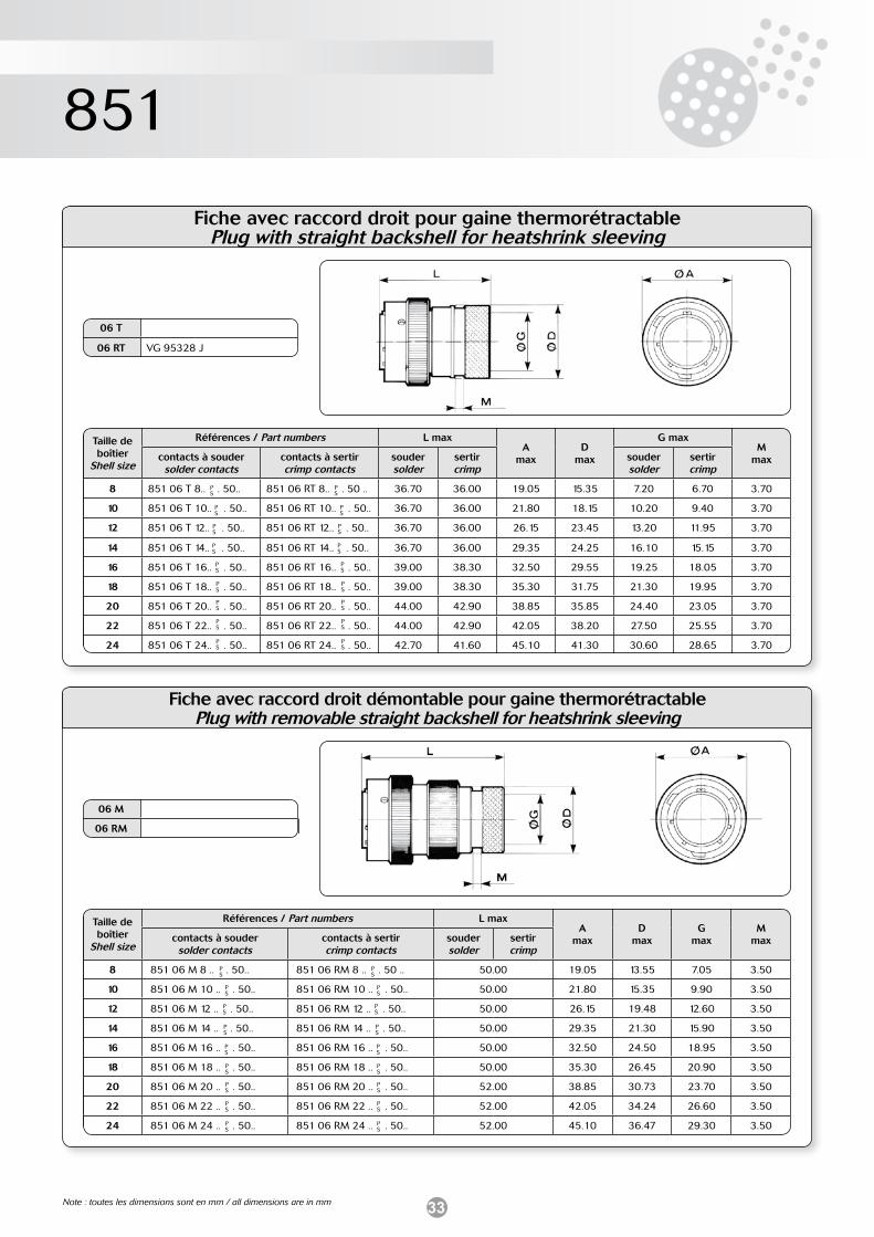
33
851
Fiche avec raccord droit pour gaine thermorétractablePlug with straight backshell for heatshrink sleeving
Fiche avec raccord droit démontable pour gaine thermorétractablePlug with removable straight backshell for heatshrink sleeving
PS
PS
PS
PS
PS
PS
PS
PS
PS
PS
PS
PS
PS
PS
PS
PS
PS
PS
06 M
06 RM
06 T
06 RT VG 95328 J
PS
PS
PS
PS
PS
PS
PS
PS
PS
PS
PS
PS
PS
PS
PS
PS
PS
PS
Taille de boîtier
Shell size
Références / Part numbers L maxA
maxD
max
G maxM
maxcontacts à soudersolder contacts
contacts à sertircrimp contacts
souder solder
sertircrimp
soudersolder
sertircrimp
8 851 06 T 8.. . 50.. 851 06 RT 8.. . 50 .. 36.70 36.00 19.05 15.35 7.20 6.70 3.70
10 851 06 T 10.. . 50.. 851 06 RT 10.. . 50.. 36.70 36.00 21.80 18.15 10.20 9.40 3.70
12 851 06 T 12.. . 50.. 851 06 RT 12.. . 50.. 36.70 36.00 26.15 23.45 13.20 11.95 3.70
14 851 06 T 14.. . 50.. 851 06 RT 14.. . 50.. 36.70 36.00 29.35 24.25 16.10 15.15 3.70
16 851 06 T 16.. . 50.. 851 06 RT 16.. . 50.. 39.00 38.30 32.50 29.55 19.25 18.05 3.70
18 851 06 T 18.. . 50.. 851 06 RT 18.. . 50.. 39.00 38.30 35.30 31.75 21.30 19.95 3.70
20 851 06 T 20.. . 50.. 851 06 RT 20.. . 50.. 44.00 42.90 38.85 35.85 24.40 23.05 3.70
22 851 06 T 22.. . 50.. 851 06 RT 22.. . 50.. 44.00 42.90 42.05 38.20 27.50 25.55 3.70
24 851 06 T 24.. . 50.. 851 06 RT 24.. . 50.. 42.70 41.60 45.10 41.30 30.60 28.65 3.70
Taille de boîtier
Shell size
Références / Part numbers L maxA
maxD
maxG
maxM
maxcontacts à soudersolder contacts
contacts à sertircrimp contacts
souder solder
sertircrimp
8 851 06 M 8 .. . 50.. 851 06 RM 8 .. . 50 .. 50.00 19.05 13.55 7.05 3.50
10 851 06 M 10 .. . 50.. 851 06 RM 10 .. . 50.. 50.00 21.80 15.35 9.90 3.50
12 851 06 M 12 .. . 50.. 851 06 RM 12 .. . 50.. 50.00 26.15 19.48 12.60 3.50
14 851 06 M 14 .. . 50.. 851 06 RM 14 .. . 50.. 50.00 29.35 21.30 15.90 3.50
16 851 06 M 16 .. . 50.. 851 06 RM 16 .. . 50.. 50.00 32.50 24.50 18.95 3.50
18 851 06 M 18 .. . 50.. 851 06 RM 18 .. . 50.. 50.00 35.30 26.45 20.90 3.50
20 851 06 M 20 .. . 50.. 851 06 RM 20 .. . 50.. 52.00 38.85 30.73 23.70 3.50
22 851 06 M 22 .. . 50.. 851 06 RM 22 .. . 50.. 52.00 42.05 34.24 26.60 3.50
24 851 06 M 24 .. . 50.. 851 06 RM 24 .. . 50.. 52.00 45.10 36.47 29.30 3.50
Note : toutes les dimensions sont en mm / all dimensions are in mm
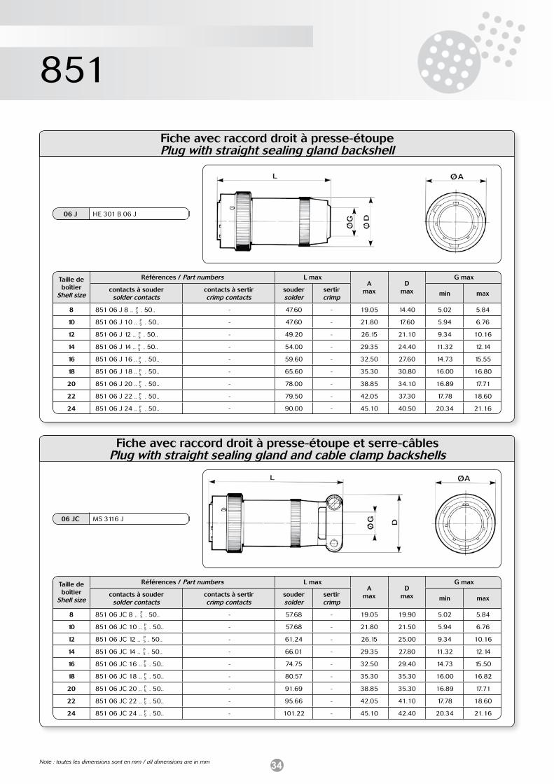
34
851
Fiche avec raccord droit à presse-étoupePlug with straight sealing gland backshell
PS
PS
PS
PS
PS
PS
PS
PS
PS
Fiche avec raccord droit à presse-étoupe et serre-câblesPlug with straight sealing gland and cable clamp backshells
PS
PS
PS
PS
PS
PS
PS
PS
PS
06 J HE 301 B 06 J
06 JC MS 3116 J
Taille de boîtier
Shell size
Références / Part numbers L maxA
maxD
max
G max
contacts à soudersolder contacts
contacts à sertircrimp contacts
souder solder
sertircrimp min max
8 851 06 J 8 .. . 50.. - 47.60 - 19.05 14.40 5.02 5.84
10 851 06 J 10 .. . 50.. - 47.60 - 21.80 17.60 5.94 6.76
12 851 06 J 12 .. . 50.. - 49.20 - 26.15 21.10 9.34 10.16
14 851 06 J 14 .. . 50.. - 54.00 - 29.35 24.40 11.32 12.14
16 851 06 J 16 .. . 50.. - 59.60 - 32.50 27.60 14.73 15.55
18 851 06 J 18 .. . 50.. - 65.60 - 35.30 30.80 16.00 16.80
20 851 06 J 20 .. . 50.. - 78.00 - 38.85 34.10 16.89 17.71
22 851 06 J 22 .. . 50.. - 79.50 - 42.05 37.30 17.78 18.60
24 851 06 J 24 .. . 50.. - 90.00 - 45.10 40.50 20.34 21.16
Taille de boîtier
Shell size
Références / Part numbers L maxA
maxD
max
G max
contacts à soudersolder contacts
contacts à sertircrimp contacts
souder solder
sertircrimp min max
8 851 06 JC 8 .. . 50.. - 57.68 - 19.05 19.90 5.02 5.84
10 851 06 JC 10 .. . 50.. - 57.68 - 21.80 21.50 5.94 6.76
12 851 06 JC 12 .. . 50.. - 61.24 - 26.15 25.00 9.34 10.16
14 851 06 JC 14 .. . 50.. - 66.01 - 29.35 27.80 11.32 12.14
16 851 06 JC 16 .. . 50.. - 74.75 - 32.50 29.40 14.73 15.50
18 851 06 JC 18 .. . 50.. - 80.57 - 35.30 35.30 16.00 16.82
20 851 06 JC 20 .. . 50.. - 91.69 - 38.85 35.30 16.89 17.71
22 851 06 JC 22 .. . 50.. - 95.66 - 42.05 41.10 17.78 18.60
24 851 06 JC 24 .. . 50.. - 101.22 - 45.10 42.40 20.34 21.16
Note : toutes les dimensions sont en mm / all dimensions are in mm
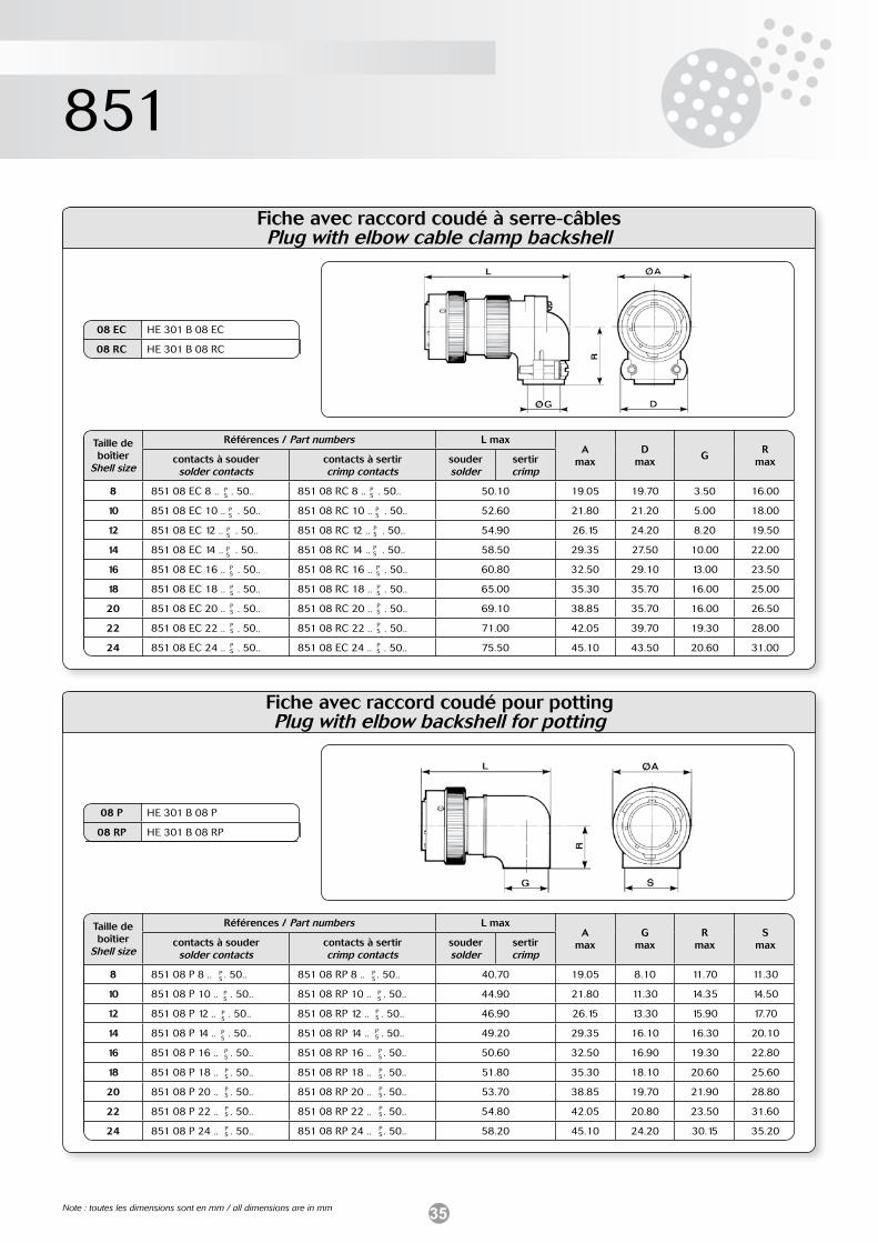
35
851
Fiche avec raccord coudé à serre-câblesPlug with elbow cable clamp backshell
PS
PS
PS
PS
PS
PS
PS
PS
PS
08 EC HE 301 B 08 EC
08 RC HE 301 B 08 RC
PS
PS
PS
PS
PS
PS
PS
PS
PS
Taille de boîtier
Shell size
Références / Part numbers L maxA
maxD
maxG
R maxcontacts à souder
solder contactscontacts à sertircrimp contacts
souder solder
sertircrimp
8 851 08 EC 8 .. . 50.. 851 08 RC 8 .. . 50.. 50.10 19.05 19.70 3.50 16.00
10 851 08 EC 10 .. . 50.. 851 08 RC 10 .. . 50.. 52.60 21.80 21.20 5.00 18.00
12 851 08 EC 12 .. . 50.. 851 08 RC 12 .. . 50.. 54.90 26.15 24.20 8.20 19.50
14 851 08 EC 14 .. . 50.. 851 08 RC 14 .. . 50.. 58.50 29.35 27.50 10.00 22.00
16 851 08 EC 16 .. . 50.. 851 08 RC 16 .. . 50.. 60.80 32.50 29.10 13.00 23.50
18 851 08 EC 18 .. . 50.. 851 08 RC 18 .. . 50.. 65.00 35.30 35.70 16.00 25.00
20 851 08 EC 20 .. . 50.. 851 08 RC 20 .. . 50.. 69.10 38.85 35.70 16.00 26.50
22 851 08 EC 22 .. . 50.. 851 08 RC 22 .. . 50.. 71.00 42.05 39.70 19.30 28.00
24 851 08 EC 24 .. . 50.. 851 08 EC 24 .. . 50.. 75.50 45.10 43.50 20.60 31.00
Fiche avec raccord coudé pour pottingPlug with elbow backshell for potting
PS
PS
PS
PS
PS
PS
PS
PS
PS
08 P HE 301 B 08 P
08 RP HE 301 B 08 RP
PS
PS
PS
PS
PS
PS
PS
PS
PS
Taille de boîtier
Shell size
Références / Part numbers L maxA
maxG
maxR
maxS
maxcontacts à soudersolder contacts
contacts à sertircrimp contacts
souder solder
sertircrimp
8 851 08 P 8 .. . 50.. 851 08 RP 8 .. . 50.. 40.70 19.05 8.10 11.70 11.30
10 851 08 P 10 .. . 50.. 851 08 RP 10 .. . 50.. 44.90 21.80 11.30 14.35 14.50
12 851 08 P 12 .. . 50.. 851 08 RP 12 .. . 50.. 46.90 26.15 13.30 15.90 17.70
14 851 08 P 14 .. . 50.. 851 08 RP 14 .. . 50.. 49.20 29.35 16.10 16.30 20.10
16 851 08 P 16 .. . 50.. 851 08 RP 16 .. . 50.. 50.60 32.50 16.90 19.30 22.80
18 851 08 P 18 .. . 50.. 851 08 RP 18 .. . 50.. 51.80 35.30 18.10 20.60 25.60
20 851 08 P 20 .. . 50.. 851 08 RP 20 .. . 50.. 53.70 38.85 19.70 21.90 28.80
22 851 08 P 22 .. . 50.. 851 08 RP 22 .. . 50.. 54.80 42.05 20.80 23.50 31.60
24 851 08 P 24 .. . 50.. 851 08 RP 24 .. . 50.. 58.20 45.10 24.20 30.15 35.20
Note : toutes les dimensions sont en mm / all dimensions are in mm
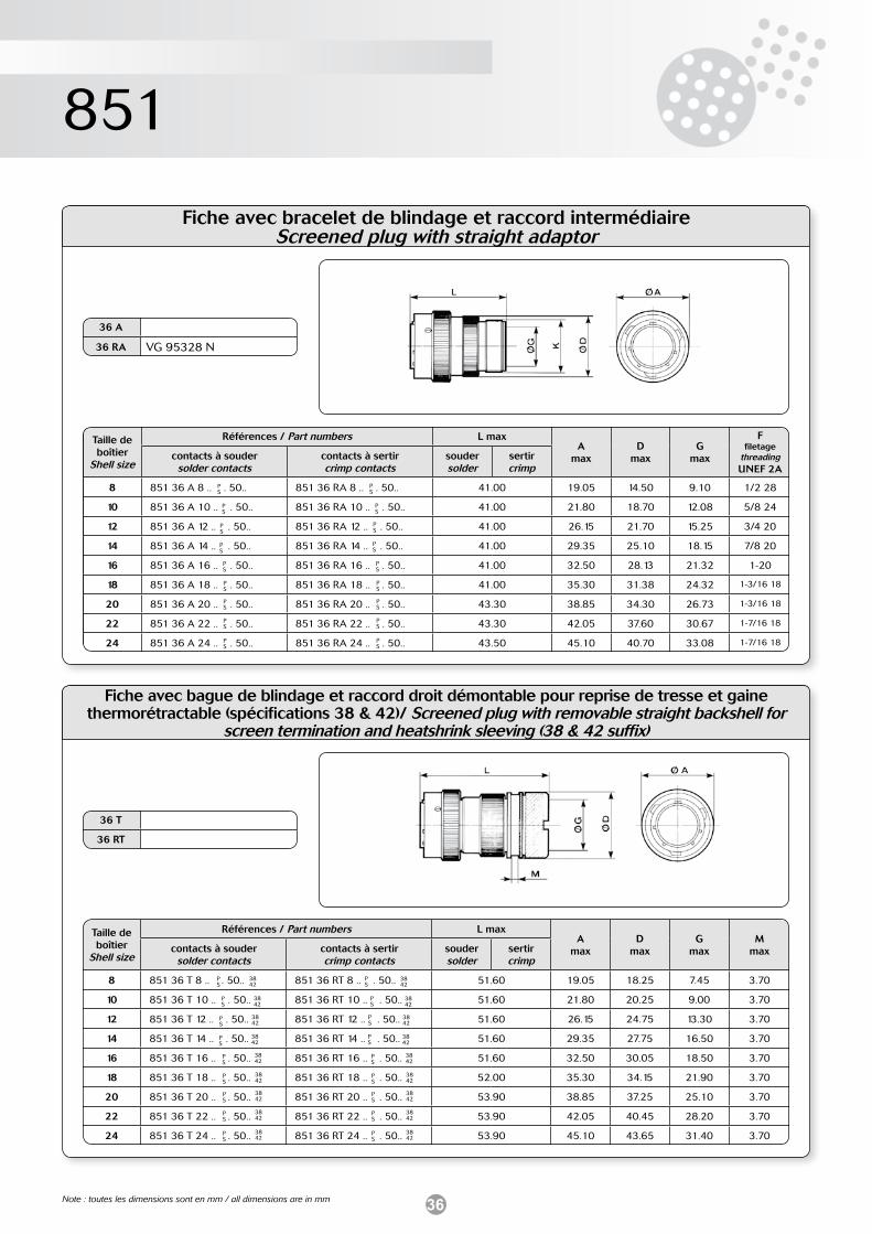
36
851
Fiche avec bracelet de blindage et raccord intermédiaireScreened plug with straight adaptor
PS
PS
PS
PS
PS
PS
PS
PS
PS
36 A
36 RA VG 95328 N
PS
PS
PS
PS
PS
PS
PS
PS
PS
Taille de boîtier
Shell size
Références / Part numbers L maxA
maxD
maxG
max
Ffiletage
threadingUNEF 2A
contacts à soudersolder contacts
contacts à sertircrimp contacts
souder solder
sertircrimp
8 851 36 A 8 .. . 50.. 851 36 RA 8 .. . 50.. 41.00 19.05 14.50 9.10 1/2 28
10 851 36 A 10 .. . 50.. 851 36 RA 10 .. . 50.. 41.00 21.80 18.70 12.08 5/8 24
12 851 36 A 12 .. . 50.. 851 36 RA 12 .. . 50.. 41.00 26.15 21.70 15.25 3/4 20
14 851 36 A 14 .. . 50.. 851 36 RA 14 .. . 50.. 41.00 29.35 25.10 18.15 7/8 20
16 851 36 A 16 .. . 50.. 851 36 RA 16 .. . 50.. 41.00 32.50 28.13 21.32 1-20
18 851 36 A 18 .. . 50.. 851 36 RA 18 .. . 50.. 41.00 35.30 31.38 24.32 1-3/16 18
20 851 36 A 20 .. . 50.. 851 36 RA 20 .. . 50.. 43.30 38.85 34.30 26.73 1-3/16 18
22 851 36 A 22 .. . 50.. 851 36 RA 22 .. . 50.. 43.30 42.05 37.60 30.67 1-7/16 18
24 851 36 A 24 .. . 50.. 851 36 RA 24 .. . 50.. 43.50 45.10 40.70 33.08 1-7/16 18
Note : toutes les dimensions sont en mm / all dimensions are in mm
PS
PS
PS
PS
PS
PS
PS
PS
PS
36 T
36 RT
PS
PS
PS
PS
PS
PS
PS
PS
PS
Taille de boîtier
Shell size
Références / Part numbers L maxA
maxD
maxG
maxM
maxcontacts à soudersolder contacts
contacts à sertircrimp contacts
souder solder
sertircrimp
8 851 36 T 8 .. . 50.. 851 36 RT 8 .. . 50.. 51.60 19.05 18.25 7.45 3.70
10 851 36 T 10 .. . 50.. 851 36 RT 10 .. . 50.. 51.60 21.80 20.25 9.00 3.70
12 851 36 T 12 .. . 50.. 851 36 RT 12 .. . 50.. 51.60 26.15 24.75 13.30 3.70
14 851 36 T 14 .. . 50.. 851 36 RT 14 .. . 50.. 51.60 29.35 27.75 16.50 3.70
16 851 36 T 16 .. . 50.. 851 36 RT 16 .. . 50.. 51.60 32.50 30.05 18.50 3.70
18 851 36 T 18 .. . 50.. 851 36 RT 18 .. . 50.. 52.00 35.30 34.15 21.90 3.70
20 851 36 T 20 .. . 50.. 851 36 RT 20 .. . 50.. 53.90 38.85 37.25 25.10 3.70
22 851 36 T 22 .. . 50.. 851 36 RT 22 .. . 50.. 53.90 42.05 40.45 28.20 3.70
24 851 36 T 24 .. . 50.. 851 36 RT 24 .. . 50.. 53.90 45.10 43.65 31.40 3.70
Fiche avec bague de blindage et raccord droit démontable pour reprise de tresse et gaine thermorétractable (spécifications 38 & 42)/ Screened plug with removable straight backshell for
screen termination and heatshrink sleeving (38 & 42 suffix)
3842
3842
3842
3842
3842
3842
3842
3842
3842
3842
3842
3842
3842
3842
3842
3842
3842
3842
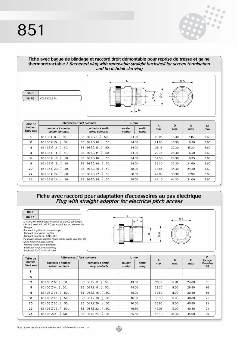
37
851
Fiche avec bague de blindage et raccord droit démontable pour reprise de tresse et gaine thermorétractable / Screened plug with removable straight backshell for screen termination
and heatshrink sleeving
36 G
36 RG VG 95328 M
Taille de boîtier
Shell size
Références / Part numbers L maxA
maxD
maxG
maxM
maxcontacts à soudersolder contacts
contacts à sertircrimp contacts
souder solder
sertircrimp
8 851 36 G 8 .. . 50.. 851 36 RG 8 .. . 50.. 54.00 19.05 16.30 7.45 3.60
10 851 36 G10 .. . 50.. 851 36 RG 10 .. . 50.. 54.00 21.80 18.30 10.30 3.60
12 851 36 G 12 .. . 50.. 851 36 RG 12 .. . 50.. 54.00 26.15 22.30 13.20 3.60
14 851 36 G 14 .. . 50.. 851 36 RG 14 .. . 50.. 54.00 29.35 25.30 16.50 3.60
16 851 36 G 16 .. . 50.. 851 36 RG 16 .. . 50.. 54.00 32.50 28.30 19.35 3.60
18 851 36 G 18 .. . 50.. 851 36 RG 18 .. . 50.. 54.00 35.30 32.30 21.60 3.60
20 851 36 G 20 .. . 50.. 851 36 RG 20 .. . 50.. 58.00 38.85 34.30 24.80 3.60
22 851 36 G 22 .. . 50.. 851 36 RG 22 .. . 50.. 58.00 42.05 38.30 27.90 3.60
24 851 36 G 24 .. . 50.. 851 36 RG 24 .. . 50.. 58.00 45.10 41.30 31.00 3.60
PS
PS
PS
PS
PS
PS
PS
PS
PS
PS
PS
PS
PS
PS
PS
PS
PS
PS
Note : toutes les dimensions sont en mm / all dimensions are in mm
PS
PS
PS
PS
PS
PS
PS
06 Z
06 RZ
PS
PS
PS
PS
PS
PS
PS
Taille de boîtier
Shell size
Références / Part numbers L maxA
maxB
maxC
max
Dfiletage
threadingPE
contacts à soudersolder contacts
contacts à sertircrimp contacts
souder solder
sertircrimp
8
10
12 851 06 Z 12 .. . 50.. 851 06 RZ 12 .. . 50.. 43.00 26.15 9.10 24.80 11
14 851 06 Z14 .. . 50.. 851 06 RZ 14 .. . 50.. 45.00 29.35 11.00 28.80 16
16 851 06 Z 16 .. . 50.. 851 06 RZ 16 .. . 50.. 45.00 32.50 11.00 30.80 16
18 851 06 Z 18 .. . 50.. 851 06 RZ 18 .. . 50.. 46.00 35.30 12.00 40.80 21
20 851 06 Z 20 .. . 50.. 851 06 RZ 20 .. . 50.. 46.50 38.85 12.00 40.80 21
22 851 06 Z 22 .. . 50.. 851 06 RZ 22 .. . 50.. 46.50 42.05 12.00 40.80 21
24 851 06 Z24 .. . 50.. 851 06 RZ 24 .. . 50.. 65.50 45.10 31.40 45.00 29
Fiche avec raccord pour adaptation d’accessoires au pas électriquePlug with straight adaptor for electrical pitch access
Le manchon intermédiaire spécial de type Z qui équipe la fiche à sertir 851 06 RZ est adapté aux accessoires de câblages.- Raccord à griffes et presse-étoupe- Raccord pour gaine polyflex- Raccord pour tuyau C.N.O.M.O.The Z type special adaptor which equips crimp plug 851 06 RZ fits following accessories.- Packing gland collet backshell- Backshell for polyflex sleeving- Backshell for C.N.O.M.O. tube
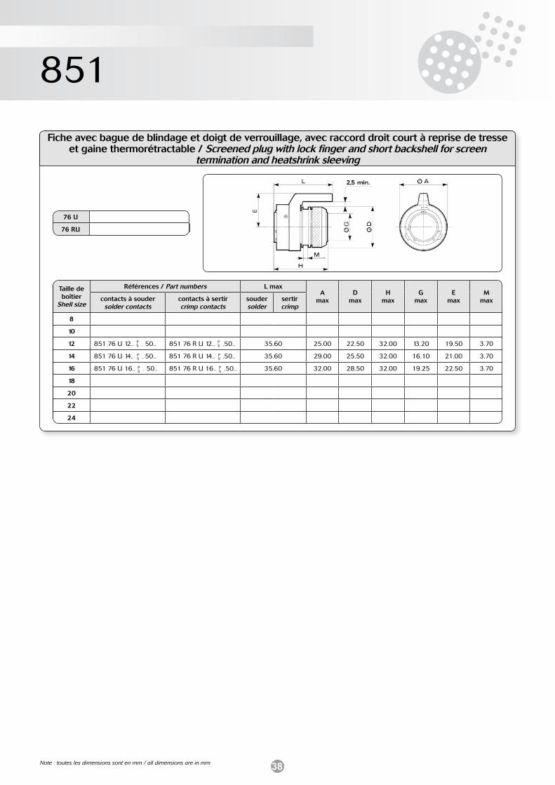
38
851
Fiche avec bague de blindage et doigt de verrouillage, avec raccord droit court à reprise de tresse et gaine thermorétractable / Screened plug with lock finger and short backshell for screen
termination and heatshrink sleeving
PS
PS
PS
76 U
76 RU
PS
PS
PS
Taille de boîtier
Shell size
Références / Part numbers L maxA
maxD
maxH
maxG
maxE
maxM
maxcontacts à soudersolder contacts
contacts à sertircrimp contacts
souder solder
sertircrimp
8
10
12 851 76 U 12.. . 50.. 851 76 R U 12.. .50.. 35.60 25.00 22.50 32.00 13.20 19.50 3.70
14 851 76 U 14.. . 50.. 851 76 R U 14.. .50.. 35.60 29.00 25.50 32.00 16.10 21.00 3.70
16 851 76 U 16.. . 50.. 851 76 R U 16.. .50.. 35.60 32.00 28.50 32.00 19.25 22.50 3.70
18
20
22
24
Note : toutes les dimensions sont en mm / all dimensions are in mm
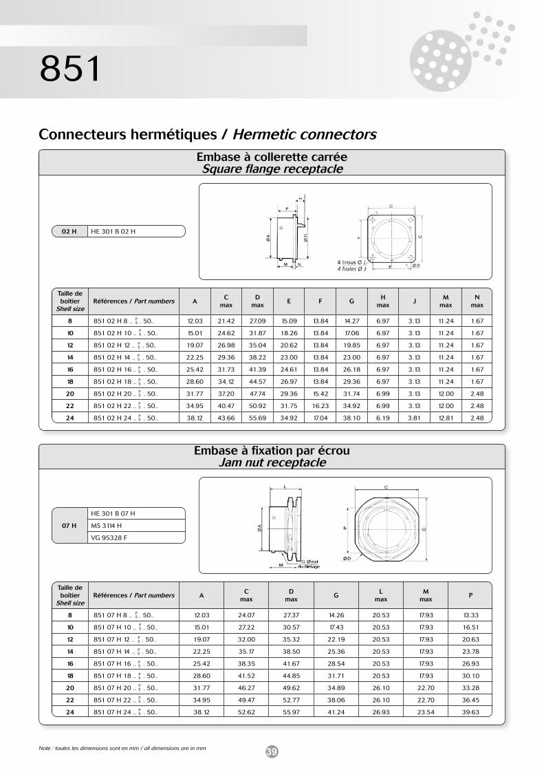
39
851
Embase à fixation par écrouJam nut receptacle
PS
PS
PS
PS
PS
PS
PS
PS
PS
07 H
HE 301 B 07 H
MS 3114 H
VG 95328 F
Taille de boîtier
Shell sizeRéférences / Part numbers A
C max
Dmax
GL
maxM
maxP
8 851 07 H 8 .. . 50.. 12.03 24.07 27.37 14.26 20.53 17.93 13.33
10 851 07 H 10 .. . 50.. 15.01 27.22 30.57 17.43 20.53 17.93 16.51
12 851 07 H 12 .. . 50.. 19.07 32.00 35.32 22.19 20.53 17.93 20.63
14 851 07 H 14 .. . 50.. 22.25 35.17 38.50 25.36 20.53 17.93 23.78
16 851 07 H 16 .. . 50.. 25.42 38.35 41.67 28.54 20.53 17.93 26.93
18 851 07 H 18 .. . 50.. 28.60 41.52 44.85 31.71 20.53 17.93 30.10
20 851 07 H 20 .. . 50.. 31.77 46.27 49.62 34.89 26.10 22.70 33.28
22 851 07 H 22 .. . 50.. 34.95 49.47 52.77 38.06 26.10 22.70 36.45
24 851 07 H 24 .. . 50.. 38.12 52.62 55.97 41.24 26.93 23.54 39.63
Connecteurs hermétiques / Hermetic connectorsEmbase à collerette carréeSquare flange receptacle
PS
PS
PS
PS
PS
PS
PS
PS
PS
02 H HE 301 B 02 H
Taille de boîtier
Shell sizeRéférences / Part numbers A
C max
Dmax
E F GH
maxJ
Mmax
Nmax
8 851 02 H 8 .. . 50.. 12.03 21.42 27.09 15.09 13.84 14.27 6.97 3.13 11.24 1.67
10 851 02 H 10 .. . 50.. 15.01 24.62 31.87 18.26 13.84 17.06 6.97 3.13 11.24 1.67
12 851 02 H 12 .. . 50.. 19.07 26.98 35.04 20.62 13.84 19.85 6.97 3.13 11.24 1.67
14 851 02 H 14 .. . 50.. 22.25 29.36 38.22 23.00 13.84 23.00 6.97 3.13 11.24 1.67
16 851 02 H 16 .. . 50.. 25.42 31.73 41.39 24.61 13.84 26.18 6.97 3.13 11.24 1.67
18 851 02 H 18 .. . 50.. 28.60 34.12 44.57 26.97 13.84 29.36 6.97 3.13 11.24 1.67
20 851 02 H 20 .. . 50.. 31.77 37.20 47.74 29.36 15.42 31.74 6.99 3.13 12.00 2.48
22 851 02 H 22 .. . 50.. 34.95 40.47 50.92 31.75 16.23 34.92 6.99 3.13 12.00 2.48
24 851 02 H 24 .. . 50.. 38.12 43.66 55.69 34.92 17.04 38.10 6.19 3.81 12.81 2.48
Note : toutes les dimensions sont en mm / all dimensions are in mm
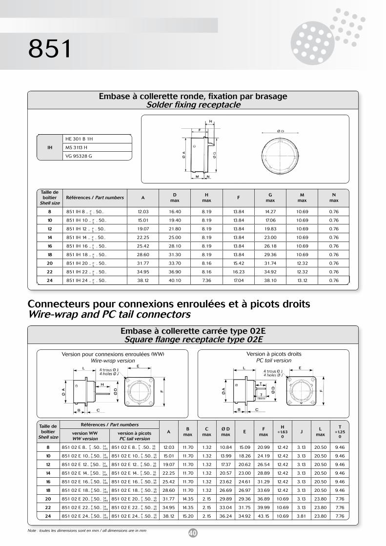
40
851
Connecteurs pour connexions enroulées et à picots droitsWire-wrap and PC tail connectors
Embase à collerette ronde, fixation par brasageSolder fixing receptacle
PS
PS
PS
PS
PS
PS
PS
PS
PS
IH
HE 301 B 1H
MS 3113 H
VG 95328 G
Taille de boîtier
Shell sizeRéférences / Part numbers A
Dmax
Hmax
FG
maxM
maxN
max
8 851 IH 8 .. . 50.. 12.03 16.40 8.19 13.84 14.27 10.69 0.76
10 851 IH 10 .. . 50.. 15.01 19.40 8.19 13.84 17.06 10.69 0.76
12 851 IH 12 .. . 50.. 19.07 21.80 8.19 13.84 19.83 10.69 0.76
14 851 IH 14 .. . 50.. 22.25 25.00 8.19 13.84 23.00 10.69 0.76
16 851 IH 16 .. . 50.. 25.42 28.10 8.19 13.84 26.18 10.69 0.76
18 851 IH 18 .. . 50.. 28.60 31.30 8.19 13.84 29.36 10.69 0.76
20 851 IH 20 .. . 50.. 31.77 33.70 8.16 15.42 31.74 12.32 0.76
22 851 IH 22 .. . 50.. 34.95 36.90 8.16 16.23 34.92 12.32 0.76
24 851 IH 24 .. . 50.. 38.12 40.10 7.36 17.04 38.10 13.12 0.76
Embase à collerette carrée type 02ESquare flange receptacle type 02E
PS
PS
PS
PS
PS
PS
PS
PS
PS
Version pour connexions enroulées (WW)Wire-wrap version
Version à picots droitsPC tail version
Taille de boîtier
Shell size
Références / Part numbers
AB
maxC
maxØ Dmax
EF
max
H+1.63
0J
Lmax
T+1.25
0version WWWW version
version à picotsPC tail version
8 851 02 E 8.. .50.. 851 02 E 8.. .50.. 12.03 11.70 1.32 10.84 15.09 20.99 12.42 3.13 20.50 9.46
10 851 02 E 10.. .50.. 851 02 E 10.. .50.. 15.01 11.70 1.32 13.99 18.26 24.19 12.42 3.13 20.50 9.46
12 851 02 E 12.. .50.. 851 02 E 12.. .50.. 19.07 11.70 1.32 17.37 20.62 26.54 12.42 3.13 20.50 9.46
14 851 02 E 14.. .50.. 851 02 E 14.. .50.. 22.25 11.70 1.32 20.57 23.00 28.89 12.42 3.13 20.50 9.46
16 851 02 E 16.. .50.. 851 02 E 16.. .50.. 25.42 11.70 1.32 23.62 24.61 31.29 12.42 3.13 20.50 9.46
18 851 02 E 18.. .50.. 851 02 E 18.. .50.. 28.60 11.70 1.32 26.69 26.97 33.69 12.42 3.13 20.50 9.46
20 851 02 E 20.. .50.. 851 02 E 20.. .50.. 31.77 14.35 2.15 29.89 29.36 36.89 10.69 3.13 23.80 7.76
22 851 02 E 22.. .50.. 851 02 E 22.. .50.. 34.95 14.35 2.15 33.04 31.75 39.99 10.69 3.13 23.80 7.76
24 851 02 E 24.. .50.. 851 02 E 24.. .50.. 38.12 15.20 2.15 36.24 34.92 43.15 10.69 3.81 23.80 7.76
PS
PS
PS
PS
PS
PS
PS
PS
PS
1640
1640
1640
1640
1640
1640
1640
1640
1640
3434A
3434A
3434A
3434A
3434A
3434A
3434A
3434A
3434A
Note : toutes les dimensions sont en mm / all dimensions are in mm
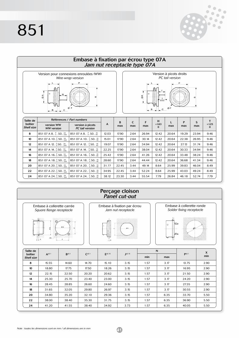
41
851
Perçage cloison Panel cut-out
Taille de boîtier
Shell sizeA±0.1 B±0.1 C±0.1 E±0.15 J±0.15
NP±0.1 X
minmin max
8 15.55 14.60 14.70 15.10 3.15 1.57 3.17 13.75 2.90
10 18.80 17.75 17.50 18.26 3.15 1.57 3.17 16.95 2.90
12 22.15 22.50 20.20 20.62 3.15 1.57 3.17 21.50 2.90
14 25.30 25.70 23.40 23.00 3.15 1.57 3.17 24.20 2.90
16 28.45 28.85 26.60 24.60 3.15 1.57 3.17 27.35 2.90
18 31.65 32.05 29.80 26.97 3.15 1.57 3.17 30.55 2.90
20 34.80 35.20 32.10 29.36 3.15 1.57 6.35 33.70 5.50
22 38.00 38.40 35.30 31.75 3.15 1.57 6.35 36.90 5.50
24 41.20 41.55 38.40 34.92 3.73 1.57 6.35 40.05 5.50
Embase à fixation par écrou type 07AJam nut receptacle type 07A
PS
PS
PS
PS
PS
PS
PS
PS
PS
Version pour connexions enroulées (WW)Wire-wrap version
Version à picots droitsPC tail version
Taille de boîtier
Shell size
Références / Part numbers
AB
maxC
maxF
max
H+1.63
0
Lmax
Pmax
Smax
T+1.25
0version WWWW version
version à picotsPC tail version
8 851 07 A 8.. .50.. 851 07 A 8.. .50.. 12.03 17.90 2.64 26.94 12.42 20.64 19.29 23.94 9.46
10 851 07 A 10.. .50.. 851 07 A 10.. .50.. 15.01 17.90 2.64 30.14 12.42 20.64 22.38 26.95 9.46
12 851 07 A 12.. .50.. 851 07 A 12.. .50.. 19.07 17.90 2.64 34.94 12.42 20.64 27.13 31.74 9.46
14 851 07 A 14.. .50.. 851 07 A 14.. .50.. 22.25 17.90 2.64 38.04 12.42 20.64 30.33 34.94 9.46
16 851 07 A 16.. .50.. 851 07 A 16.. .50.. 25.42 17.90 2.64 41.26 12.42 20.64 33.48 38.24 9.46
18 851 07 A 18.. .50.. 851 07 A 18.. .50.. 28.60 17.90 2.64 44.44 12.42 20.64 36.68 41.34 9.46
20 851 07 A 20.. .50.. 851 07 A 20.. .50.. 31.77 22.45 3.44 49.14 8.64 25.99 39.83 46.04 8.49
22 851 07 A 22.. .50.. 851 07 A 22.. .50.. 34.95 22.45 3.44 52.24 8.64 25.99 43.03 49.24 8.49
24 851 07 A 24.. .50.. 851 07 A 24.. .50.. 38.12 23.30 3.44 55.54 7.79 26.84 46.18 52.74 7.79
PS
PS
PS
PS
PS
PS
PS
PS
PS
1640
1640
1640
1640
1640
1640
1640
1640
1640
3434A
3434A
3434A
3434A
3434A
3434A
3434A
3434A
3434A
Embase à collerette carréeSquare flange receptacle
Embase à fixation par écrouJam nut receptacle
Embase à collerette rondeSolder fixing receptacle
Note : toutes les dimensions sont en mm / all dimensions are in mm
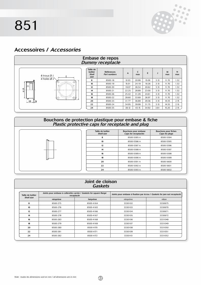
42
851
Embase de reposDummy receptacle
Accessoires / Accessories
Taille de boîtierShell size
Références Part numbers A
Cmax
E JM
maxN
max
8 8500-18 12.03 20.99 15.09 3.13 11.70 1.32
10 8500-19 15.01 24.19 18.26 3.13 11.70 1.32
12 8500-20 19.07 26.54 20.62 3.13 11.70 1.32
14 8500-21 22.25 28.89 23.00 3.13 11.70 1.32
16 8500-26 25.42 31.29 24.61 3.13 11.70 1.32
18 8500-22 28.60 33.69 26.97 3.13 11.70 1.32
20 8500-23 31.77 36.89 29.36 3.13 14.35 2.15
22 8500-24 34.95 39.99 31.75 3.13 14.35 2.15
24 8500-25 38.12 43.15 34.92 3.81 15.20 2.15
Bouchons de protection plastique pour embase & fichePlastic protective caps for receptacle and plug
Taille de boîtierShell size
Bouchons pour embase Caps for receptacles
Bouchons pour fiches Caps for plugs
8 8500-5585 A 8500-5594
10 8500-5586 A 8500-5595
12 8500-5587 A 8500-5596
14 8500-5588 A 8500-5597
16 8500-5589 A 8500-5598
18 8500-5590 A 8500-5599
20 8500-5591 A 8500-5600
22 8500-5592 A 8500-5601
24 8500-5593 A 8500-5602
Joint de cloisonGaskets
Taille de boîtierShell size
Joints pour embase à collerette carrée / Gaskets for square flange receptacle Joints pour embase à fixation par écrou / Gaskets for jam nut receptacle
néoprène fairprène néoprène vitton
8 8500-275 8500-4164 3330102 3330675
10 8500-276 8500-4165 3330103 3330670
12 8500-277 8500-4166 3330104 3330671
14 8500-278 8500-4167 3330105 3330672
16 8500-283 8500-4168 3330106 3331048
18 8500-279 8500-4169 3330107 3331049
20 8500-280 8500-4170 3330108 3331050
22 8500-281 8500-4171 3330109 3331051
24 8500-282 8500-4172 3330110 3331052
Note : toutes les dimensions sont en mm / all dimensions are in mm
43
Notes / Notes
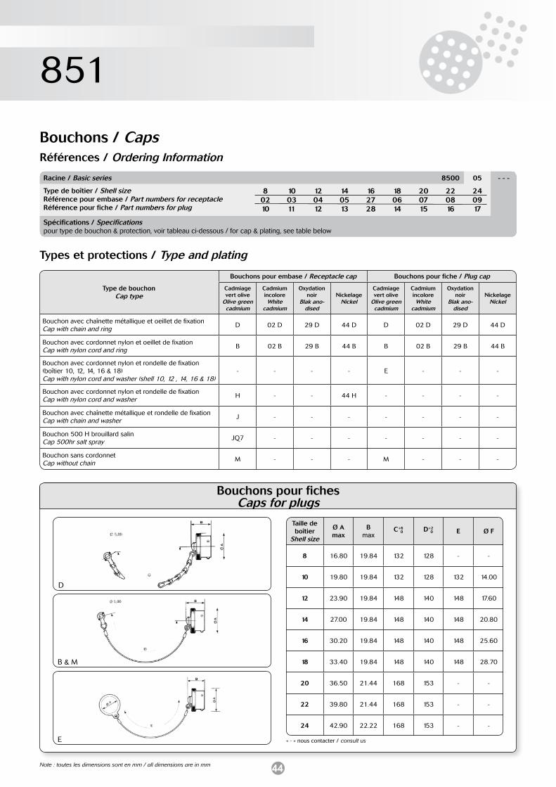
44
851
Type de bouchonCap type
Bouchons pour embase / Receptacle cap Bouchons pour fiche / Plug cap
Cadmiage vert olive
Olive green cadmium
Cadmium incoloreWhite
cadmium
Oxydation noir
Blak ano-dised
NickelageNickel
Cadmiage vert olive
Olive green cadmium
Cadmium incoloreWhite
cadmium
Oxydation noir
Blak ano-dised
NickelageNickel
Bouchon avec chaînette métallique et oeillet de fixationCap with chain and ring D 02 D 29 D 44 D D 02 D 29 D 44 D
Bouchon avec cordonnet nylon et oeillet de fixationCap with nylon cord and ring B 02 B 29 B 44 B B 02 B 29 B 44 B
Bouchon avec cordonnet nylon et rondelle de fixation (boîtier 10, 12, 14, 16 & 18)Cap with nylon cord and washer (shell 10, 12 , 14, 16 & 18)
- - - - E - - -
Bouchon avec cordonnet nylon et rondelle de fixationCap with nylon cord and washer H - - 44 H - - - -
Bouchon avec chaînette métallique et rondelle de fixationCap with chain and washer J - - - - - - -
Bouchon 500 H brouillard salinCap 500hr salt spray JQ7 - - - - - - -
Bouchon sans cordonnetCap without chain M - - - M - - -
Bouchons / CapsRéférences / Ordering Information
Racine / Basic series 8500 05 - - -
Type de boîtier / Shell sizeRéférence pour embase / Part numbers for receptacleRéférence pour fiche / Part numbers for plug
80210
100311
120412
140513
162728
180614
200715
220816
240917
Spécifications / Specificationspour type de bouchon & protection, voir tableau ci-dessous / for cap & plating, see table below
Types et protections / Type and plating
Bouchons pour fiches Caps for plugs
Taille de boîtier
Shell size
Ø Amax
Bmax
C+6 0 D+2
0 E Ø F
8 16.80 19.84 132 128 - -
10 19.80 19.84 132 128 132 14.00
12 23.90 19.84 148 140 148 17.60
14 27.00 19.84 148 140 148 20.80
16 30.20 19.84 148 140 148 25.60
18 33.40 19.84 148 140 148 28.70
20 36.50 21.44 168 153 - -
22 39.80 21.44 168 153 - -
24 42.90 22.22 168 153 - -
« - » nous contacter / consult us
D
B & M
E
Note : toutes les dimensions sont en mm / all dimensions are in mm
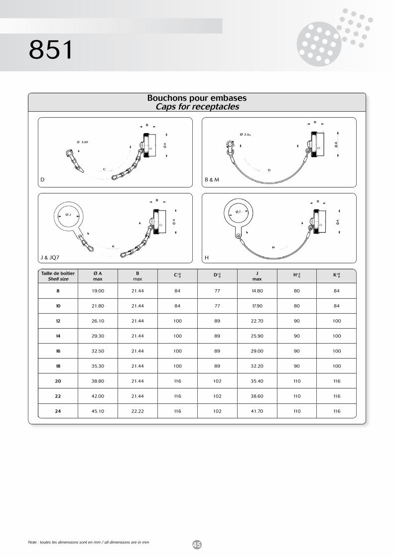
45
851
Bouchons pour embasesCaps for receptacles
D
J & JQ7
B & M
H
Taille de boîtierShell size
Ø Amax
Bmax
C+6 0 D+2
0J
maxH+2 0 K+6
0
8 19.00 21.44 84 77 14.80 80 84
10 21.80 21.44 84 77 17.90 80 84
12 26.10 21.44 100 89 22.70 90 100
14 29.30 21.44 100 89 25.90 90 100
16 32.50 21.44 100 89 29.00 90 100
18 35.30 21.44 100 89 32.20 90 100
20 38.80 21.44 116 102 35.40 110 116
22 42.00 21.44 116 102 38.60 110 116
24 45.10 22.22 116 102 41.70 110 116
Note : toutes les dimensions sont en mm / all dimensions are in mm
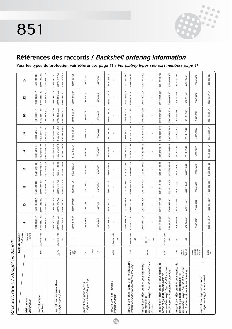
46
851
Références des raccords / Backshell ordering informationPour les types de protection voir références page 11 / For plating types see part numbers page 11
24
85
00
-58
90
LP
85
00
-58
90
11
0
85
00
-58
90
20
2
85
00
-247
7 9
00
85
00
-247
7 9
02
85
00
-247
7 9
03
85
00
-15
67
LP
85
00
-474
85
00
-69
0
85
00
-45
6 L
P
- -
85
00
-40
29
LP
85
00
-40
29
11
0
-
85
00
-40
53
90
0
- -
85
00
-89
82
90
0
-
85
00
-89
82
90
3
851
T 2
4-3
8
851
T 2
4-4
2
85
00
-58
81
85
00
-59
08
LP
22
85
00
-58
89
LP
85
00
-58
89
11
0
85
00
-58
89
20
2
85
00
-247
6 9
00
85
00
-247
6 9
02
85
00
-247
6 9
03
85
00
-15
66
LP
85
00
-47
3
85
00
-68
9
85
00
-31
86
LP
- -
85
00
-40
28
LP
85
00
-40
28
11
0
-
85
00
-40
52
90
0
- -
85
00
-89
81
90
0
-
85
00
-89
81
90
3
851
T 2
2-3
8
851
T 2
2-4
2
85
00
-58
80
85
00
-59
07 L
P
20
85
00
-58
88
LP
85
00
-58
88
11
0
85
00
-58
88
20
2
85
00
-247
5 9
00
85
00
-247
5 9
02
85
00
-247
5 9
03
85
00
-15
65
LP
85
00
-472
85
00
-68
8
85
00
-31
85
LP
- -
85
00
-40
27
LP
85
00
-40
27
11
0
-
85
00
-40
51 9
00
- -
85
00
-89
80
90
0
-
85
00
-89
80
90
3
851
T 2
0-3
8
851
T 2
0-4
2
85
00
-587
9
85
00
-59
06
LP
18
85
00
-58
87 L
P
85
00
-58
87 1
10
85
00
-58
87 2
02
85
00
-247
4 9
00
85
00
-247
4 9
02
85
00
-247
4 9
03
85
00
-15
64
LP
85
00
-47
1
85
00
-687
85
00
-45
3 L
P
- -
85
00
-40
26
LP
85
00
-40
26
11
0
-
85
00
-40
50
90
0
- -
85
00
-897
9 9
00
-
85
00
-897
9 9
03
851
T 1
8-3
8
851
T 1
8-4
2
85
00
-587
8
85
00
-59
05
LP
16
85
00
-58
86
LP
85
00
-58
86
11
0
85
00
-58
86
20
2
85
00
-247
3 9
00
85
00
-247
3 9
02
85
00
-247
3 9
03
85
00
-15
63
LP
85
00
-47
0
85
00
-68
6
85
00
-45
2 L
P
- -
85
00
-40
25
LP
85
00
-40
25
11
0
-
85
00
-40
49
90
0
- -
85
01
-01
90
90
0
-
85
01
-01
90
90
3
851
T 1
6-3
8
851
T 1
6-4
2
85
00
-587
7
85
00
-59
04
LP
14
85
00
-58
85
LP
85
00
-58
85
11
0
85
00
-58
85
20
2
85
00
-247
2 9
00
85
00
-247
2 9
02
85
00
-247
2 9
03
85
00
-15
62
LP
85
00
-46
9
85
00
-68
5
85
00
-451
LP
- -
85
00
-40
24
LP
85
00
-40
24
11
0
-
85
00
-40
48
90
0
- -
85
00
-897
8 9
00
-
85
00
-897
8 9
03
851
T 1
4-3
8
851
T 1
4-4
2
85
00
-587
6
85
00
-59
03
LP
12
85
00
-58
84
LP
85
00
-58
84
11
0
85
00
-58
84
20
2
85
00
-247
1 9
00
85
00
-247
1 9
02
85
00
-247
1 9
03
85
00
-15
61
LP
85
00
-46
8
85
00
-68
4
85
00
-45
0 L
P
- -
85
00
-40
23
LP
85
00
-40
23
11
0
-
85
00
-40
47 9
00
- -
85
01
-01
89
90
0
-
85
01
-01
89
90
3
851
T 1
2-3
8
851
T 1
2-4
2
85
00
-587
5
85
00
-59
02
LP
10
85
00
-58
83
LP
85
00
-58
83
11
0
85
00
-58
83
20
2
85
00
-247
0 9
00
85
00
-247
0 9
02
85
00
-247
0 9
03
85
00
-15
60
LP
85
00
-46
7
85
00
-68
3
85
00
-44
9 L
P
- -
85
00
-40
22
LP
85
00
-40
22
11
0
-
85
00
-40
46
90
0
- -
85
00
-897
7 9
00
-
85
00
-897
7 9
03
851
T 1
0-3
8
851
T 1
0-4
2
85
00
-587
4
85
00
-59
01
LP
8
85
00
-58
82
LP
85
00
-58
82
11
0
85
00
-58
82
20
2
85
00
-24
69
90
0
85
00
-24
69
90
2
85
00
-24
69
90
3
85
00
-15
59
LP
85
00
-46
6
85
00
-68
2
85
00
-44
8 L
P
- -
85
00
-40
21
LP
85
00
-40
21
11
0
-
85
00
-40
45
90
0
- -
85
01
-01
88
90
0
-
85
01
-01
88
90
3
851
T 0
8-3
8
851
T 0
8-4
2
85
00
-587
3
85
00
-59
00
LP
taill
e d
e b
oît
ier
shel
l siz
e
prot
ectio
n pl
atin
g
-
29
ou/
or
031
44 -
29
ou/
or
031
44 - - -
29
ou/
or
031
44 -
29
ou/
or
031
44 -
29
ou/
or
031
44 -
29
ou/
or
031
44
38
42 -
E/R
/R
C
écro
unu
tP/
RP
P RP
A/R
A
T/RT
M/R
M
G/R
G
T/RT
spec
ifi-
catio
n 3
8 &
42
pres
se-
étou
pese
alin
g gl
and
écro
unu
t
dé
sig
nati
on
desi
gnat
ion
racc
ord
sim
ple
back
nut
racc
ord
droi
t à
serr
e-câ
bles
stra
ight
cab
le c
lam
p
racc
ord
droi
t po
ur p
ottin
gst
raig
ht b
acks
hell
for
potti
ng
racc
ord
droi
t in
term
édia
irest
raig
ht a
dapt
or
racc
ord
droi
t po
ur g
aine
the
rmor
étra
ctab
lest
raig
ht b
acks
hell
for
heat
shrin
k sl
eevi
ng
racc
ord
droi
t dé
mon
tabl
e po
ur g
aine
the
r-m
orét
ract
able
rem
ova
ble
stra
ight
bac
kshe
ll fo
r he
atsh
rink
slee
ving
racc
ord
droi
t dé
mon
tabl
e po
ur r
epris
e de
tr
esse
et
gain
e th
erm
orét
ract
able
rem
ova
ble
stra
ight
bac
kshe
ll fo
r sc
reen
te
rmin
atio
n an
d he
atsh
rink
slee
ving
racc
ord
droi
t dé
mon
tabl
e po
ur r
epris
e de
tr
esse
et
gain
e th
erm
orét
ract
able
rem
ova
ble
stra
ight
bac
kshe
ll fo
r sc
reen
te
rmin
atio
n an
d he
atsh
rink
slee
ving
Jra
ccor
d dr
oit à
pres
se-é
toup
est
raig
ht s
ealin
g gl
and
back
shel
l
EC AC
Rac
cord
s dr
oits
/ S
trai
ght b
acks
hells
Pottin
g
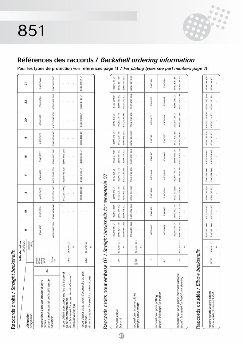
47
851
Références des raccords / Backshell ordering informationPour les types de protection voir références page 11 / For plating types see part numbers page 11
Rac
cord
s dr
oits
/ S
trai
ght b
acks
hells
24
85
00
-58
81
85
00
-59
97 9
00
- - -
85
00
-81
91
A L
P
- -
22
85
00
-58
80
85
00
-59
96
90
0
- - -
85
00
-81
90
LP
- -
20
85
00
-587
9
85
00
-59
95
90
0
- - -
85
00
-81
89
LP
- -
18
85
00
-587
8
85
00
-59
94
90
0
- - -
85
00
-81
88
LP
- -
16
85
00
-587
7
85
00
-59
93
90
0
85
00
-847
6 9
00
- -
85
00
-81
87 L
P
- -
14
85
00
-587
6
85
00
-59
92
90
0
85
00
-847
5 9
00
- -
85
00
-81
86
LP
- -
12
85
00
-587
5
85
00
-59
91
90
0
85
00
-847
4 9
00
- -
85
00
-81
85
LP
- -
10
85
00
-587
4
85
00
-59
90
90
0
- - - - - -
8
85
00
-587
3
85
00
-59
89
90
0
- - - - - -
taill
e d
e b
oît
ier
shel
l siz
e
prot
ectio
n pl
atin
g
-
29
ou/
or
031
44 -
29
ou/
or
031
44
pres
se-
étou
pese
alin
g gl
and
écr
ounu
t
U/R
U
Z/R
Z
dé
sig
nati
on
desi
gnat
ion
JC
racc
ord
droi
t co
urt po
ur r
epris
e de
tre
sse
et
gain
e th
erm
orét
ract
able
sho
rt b
acks
hell
for
scre
en te
rmin
atio
n an
d he
atsh
rink
slee
ving
racc
ord
pour
ada
ptat
ion
d’ac
cess
oire
au
pas
élec
triq
uest
raig
ht a
dapt
or
for
elec
tric
al p
itch
acce
ss
racc
ord
droi
t à
pres
se-é
toup
e et
ser
re-
câbl
esst
raig
ht s
ealin
g gl
and
and
cabl
e cl
amp
back
shel
l
Rac
cord
s dr
oits
pou
r em
base
07
/ S
trai
ght b
acks
hells
for
rece
ptac
le 0
7
85
00
-381
LP
85
00
-381
11
0
85
00
-381
20
2
85
00
-17
97 9
00
- -
85
00
-474
85
00
-69
0
85
00
-478
4 L
P
85
00
-478
4 1
10
-
85
00
-38
0 L
P
85
00
-38
0 1
10
85
00
-38
0 2
02
85
00
-17
96
90
0
- -
85
00
-47
3
85
00
-68
9
85
00
-478
3 L
P
85
00
-478
3 1
10
-
85
00
-37
9 L
P
85
00
-37
9 1
10
85
00
-37
9 2
02
85
00
-17
95
90
0
- -
85
00
-472
85
00
-68
8
85
00
-478
2 L
P
85
00
-478
2 1
10
-
85
00
-37
8 L
P
85
00
-37
8 1
10
85
00
-37
8 2
02
85
00
-17
94
90
0
- -
85
00
-47
1
85
00
-687
85
00
-47
81
LP
85
00
-47
81
11
0
-
85
00
-37
7 L
P
85
00
-37
7 1
10
85
00
-37
7 2
02
85
00
-17
93
90
0
- -
85
00
-47
0
85
00
-68
6
85
00
-47
80
LP
85
00
-47
80
11
0
-
85
00
-37
6 L
P
85
00
-37
6 1
10
85
00
-37
6 2
02
85
00
-17
92
90
0
- -
85
00
-46
9
85
00
-68
5
85
00
-47
79
LP
85
00
-47
79
11
0
-
85
00
-37
5 L
P
85
00
-37
5 1
10
85
00
-37
5 2
02
85
00
-17
91
90
0
- -
85
00
-46
8
85
00
-68
4
85
00
-47
78
LP
85
00
-47
78
11
0
-
85
00
-374
LP
85
00
-374
11
0
85
00
-374
20
2
85
00
-17
90
90
0
- -
85
00
-46
7
85
00
-68
3
85
00
-47
77
LP
85
00
-47
77
11
0
-
85
00
-83
47 L
P
85
00
-83
47 1
10
85
00
-83
47 2
02
85
00
-83
51 9
00
- -
85
00
-46
6
85
00
-68
2
85
00
-47
76
LP
85
00
-47
76
11
0
-
-
29
ou/
or
031
44 -
29
ou/
or
031
44 -
29
ou/
or
031
44
E/R
/RC
P RP
T/RT
racc
ord
sim
ple
back
nut
racc
ord
droi
t à
serr
e-câ
bles
stra
ight
cab
le c
lam
p
racc
ord
droi
t po
ur p
ottin
gst
raig
ht b
acks
hell
for
potti
ng
racc
ord
droi
t po
ur g
aine
the
rmor
étra
ctab
lest
raig
ht b
acks
hell
for
heat
shrin
k sl
eevi
ng
EC AC
Rac
cord
s co
udés
/ E
lbo
w b
acks
hells
85
00
-79
9 9
00
85
00
-79
9 9
02
-
85
00
-32
25
90
0
85
00
-32
25
90
2
-
85
00
-32
24
90
0
85
00
-32
24
90
2
-
85
00
-79
6 9
00
85
00
-79
6 9
02
-
85
00
-79
5 9
00
85
00
-79
5 9
02
-
85
00
-79
4 9
00
85
00
-79
4 9
02
-
85
00
-79
3 9
00
85
00
-79
3 9
02
-
85
00
-79
2 9
00
85
00
-79
2 9
02
-
85
00
-79
1 9
00
85
00
-79
1 9
02
-
-
29
ou/
or
031
44
EC/R
Cra
ccor
d co
udé
à se
rre-
câbl
esel
bow
cab
le c
lam
p ba
cksh
ell
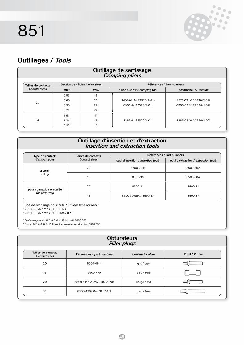
48
851
Outillages / ToolsOutillage de sertissage
Crimping pliers
Tailles de contacts Contact sizes
Section de câbles / Wire sizes Références / Part numbers
mm² AWG pince à sertir / crimping tool positionneur / locator
20
0.93
0.60
0.38
0.21
18
20
22
24
8476-01 (M 22520/2-01)
8365 (M 22520/1-01)
8476-02 (M 22520/2-02)
8365-02 (M 22520/1-02)
16
1.91
1.34
0.93
14
16
18
8365 (M 22520/1-01) 8365-02 (M 22520/1-02)
]]
Outillage d’insertion et d’extractionInsertion and extraction tools
Type de contacts Contact types
Tailles de contactsContact sizes
Références / Part numbers
outil d’insertion / insertion tools outil d’extraction / extraction tools
à sertircrimp
20 8500-29B* 8500-36A
16 8500-39 8500-38A
pour connexion enrouléefor wire-wrap
20 8500-31 8500-31
16 8500-39 ou/or 8500-37 8500-37
Tube de rechange pour outil / Square tube for tool :• 8500-36A : ref. 8500-1163 • 8500-38A : ref. 8500-1486 021
* Sauf arrangements 8-2, 8-3, 8-4, 12-14 : outil 8500-93B
* Except 8-2, 8-3, 8-4, 12-14 contact layouts : insertion tool 8500-93B
ObturateursFiller plugs
Tailles de contacts Contact sizes Références / part numbers Couleur / Colour Profil / Profile
20 8500-4144 gris / grey
16 8500-479 bleu / blue
20 8500-4144 A (MS 3187 A 20) rouge / red
16 8500-4267 (MS 3187-16) bleu / blue
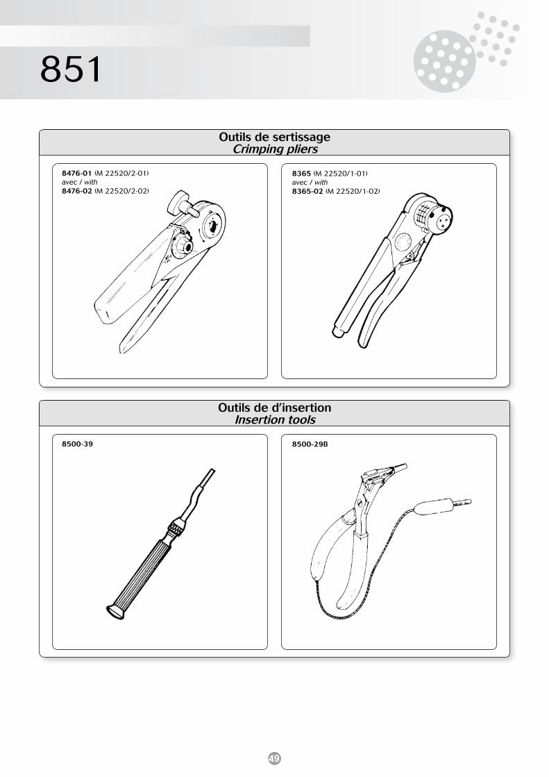
49
851
Outils de sertissageCrimping pliers
8476-01 (M 22520/2-01)avec / with8476-02 (M 22520/2-02)
8365 (M 22520/1-01)avec / with8365-02 (M 22520/1-02)
Outils de d’insertion Insertion tools
8500-39 8500-29B
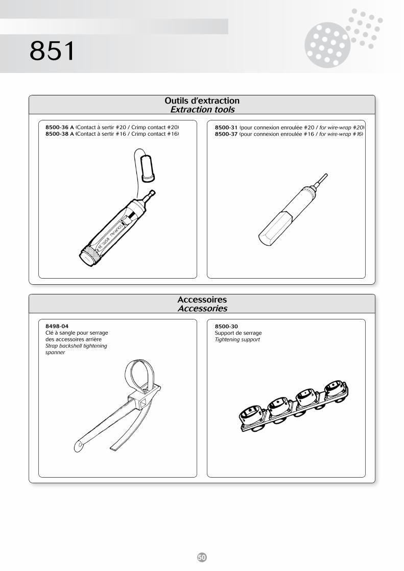
50
851
Outils d’extractionExtraction tools
8500-36 A (Contact à sertir #20 / Crimp contact #20)8500-38 A (Contact à sertir #16 / Crimp contact #16)
8500-31 (pour connexion enroulée #20 / for wire-wrap #20)8500-37 (pour connexion enroulée #16 / for wire-wrap #16)
Accessoires Accessories
8498-04 Clé à sangle pour serrage des accessoires arrièreStrap backshell tightening spanner
8500-30Support de serrageTightening support
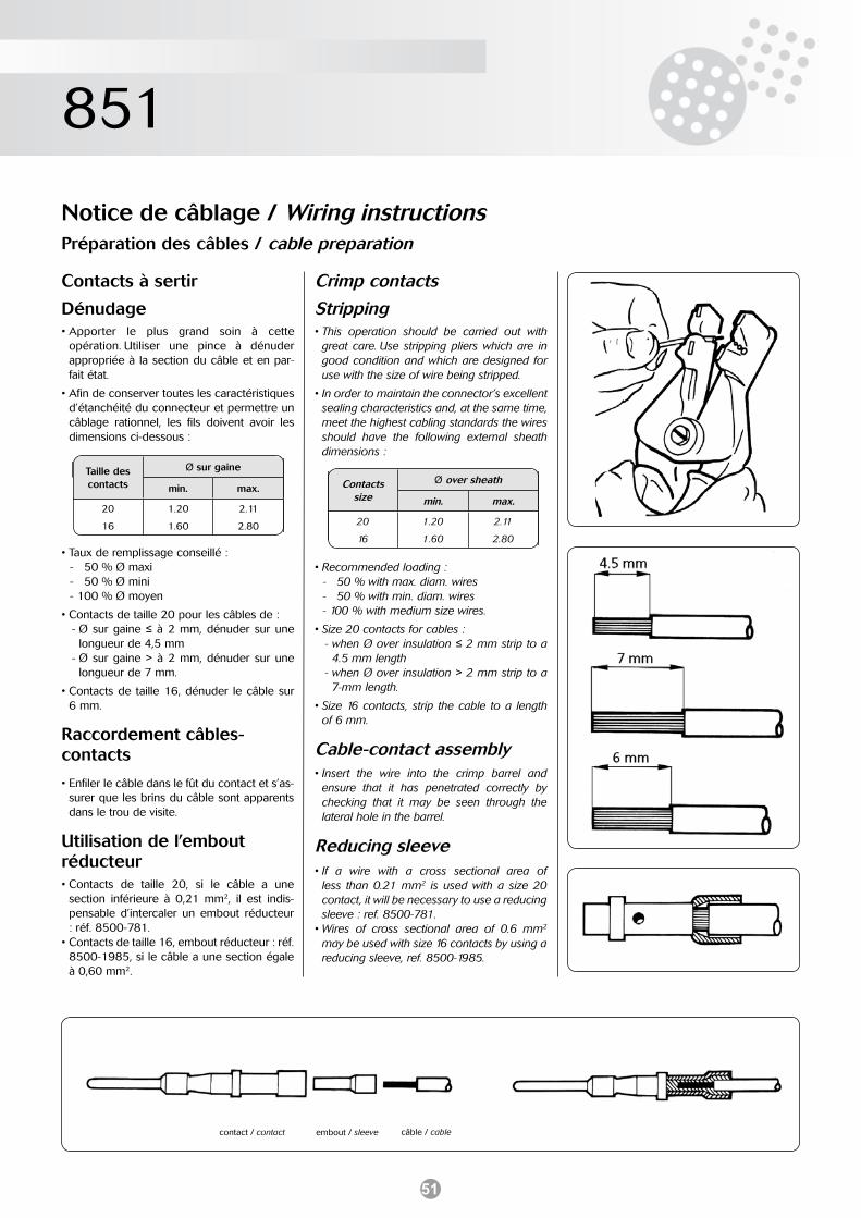
51
851
Notice de câblage / Wiring instructionsPréparation des câbles / cable preparation
Contacts à sertir Crimp contacts
Dénudage Stripping• Apporter le plus grand soin à cette
opération. Utiliser une pince à dénuder appropriée à la section du câble et en par-fait état.
• Afin de conserver toutes les caractéristiques d’étanchéité du connecteur et permettre un câblage rationnel, les fils doivent avoir les dimensions ci-dessous :
• Taux de remplissage conseillé :- 050 % Ø maxi- 050 % Ø mini- 100 % Ø moyen
• Contacts de taille 20 pour les câbles de :- Ø sur gaine ≤ à 2 mm, dénuder sur une
longueur de 4,5 mm- Ø sur gaine > à 2 mm, dénuder sur une
longueur de 7 mm.
• Contacts de taille 16, dénuder le câble sur 6 mm.
Raccordement câbles-contacts
• Enfiler le câble dans le fût du contact et s’as-surer que les brins du câble sont apparents dans le trou de visite.
Utilisation de l’embout réducteur• Contacts de taille 20, si le câble a une
section inférieure à 0,21 mm2, il est indis-pensable d’intercaler un embout réducteur : réf. 8500-781.
• Contacts de taille 16, embout réducteur : réf. 8500-1985, si le câble a une section égale à 0,60 mm2.
contact / contact embout / sleeve câble / cable
• This operation should be carried out with great care. Use stripping pliers which are in good condition and which are designed for use with the size of wire being stripped.
• In order to maintain the connector’s excellent sealing characteristics and, at the same time, meet the highest cabling standards the wires should have the following external sheath dimensions :
• Recommended loading :- 050 % with max. diam. wires - 050 % with min. diam. wires- 100 % with medium size wires.
• Size 20 contacts for cables :- when Ø over insulation ≤ 2 mm strip to a
4.5 mm length- when Ø over insulation > 2 mm strip to a
7-mm length.
• Size 16 contacts, strip the cable to a length of 6 mm.
Cable-contact assembly• Insert the wire into the crimp barrel and
ensure that it has penetrated correctly by checking that it may be seen through the lateral hole in the barrel.
Reducing sleeve• If a wire with a cross sectional area of
less than 0.21 mm2 is used with a size 20 contact, it will be necessary to use a reducing sleeve : ref. 8500-781.
• Wires of cross sectional area of 0.6 mm2 may be used with size 16 contacts by using a reducing sleeve, ref. 8500-1985.
Taille des contacts
Ø sur gaine
min. max.
20
16
1.20
1.60
2.11
2.80
Contacts size
Ø over sheath
min. max.
20
16
1.20
1.60
2.11
2.80
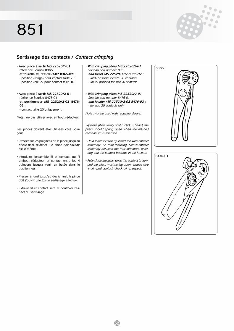
52
851
Sertissage des contacts / Contact crimping
• Avec pince à sertir MS 22520/1-01référence Souriau 8365et tourelle MS 22520/1-02 8365-02:- position «rouge» pour contact taille 20- position «bleue» pour contact taille 16.
• Avec pince à sertir MS 22520/2-01référence Souriau 8476-01et positionneur MS 22520/2-02 8476-02 :- contact taille 20 uniquement.
Nota : ne pas utiliser avec embout réducteur.
Les pinces doivent être utilisées côté poin-çons.
• Presser sur les poignées de la pince jusqu’au déclic final, relâcher ; la pince doit s’ouvrir d’elle-même.
• Introduire l’ensemble fil et contact, ou fil embout réducteur et contact entre les 4 poinçons jusqu’à venir en butée dans le positionneur.
• Presser à fond jusqu’au déclic final, la pince doit s’ouvrir une fois le sertissage effectué.
• Extraire fil et contact serti et contrôler l’as-pect du sertissage.
• With crimping pliers MS 22520/1-01Souriau part number 8365and turret MS 22520/1-02 8365-02 :- «red» position for size 20 contacts- «blue» position for size 16 contacts.
• With crimping pliers MS 22520/2-01Souriau part number 8476-01and locator MS 22520/2-02 8476-02 :- for size 20 contacts only.
Note : not be used with reducing sleeve.
Squeeze pliers firmly until a click is heard, the pliers should spring open when the ratched mechanism is released.
• Hold indentor side up-insert the wire-contact assembly or mire-reducing sleeve-contact assembly between the four indentors, ensu-ring that the contact bottoms in the locator.
• Fully close the jaws, once the contact is crim-ped the pliers must spring open remove wire + crimped contact, check crimp aspect.
8365
8476-01
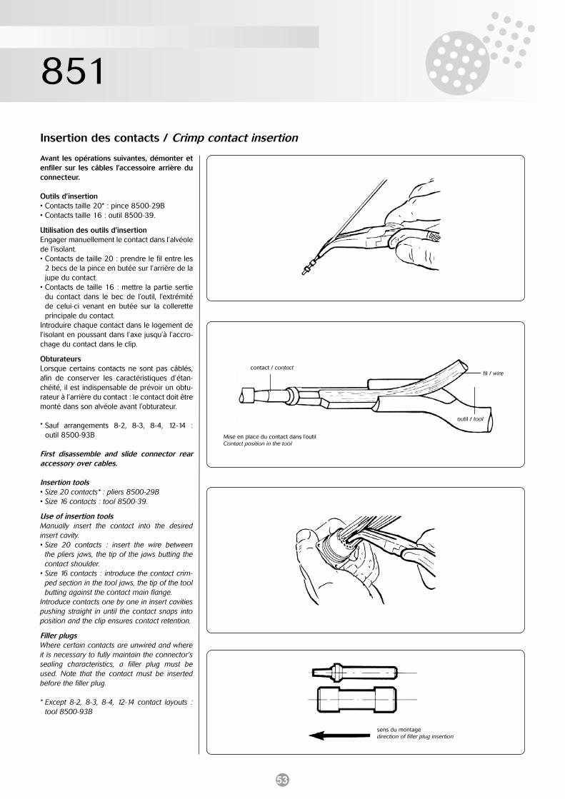
53
851
Insertion des contacts / Crimp contact insertion
Avant les opérations suivantes, démonter et enfiler sur les câbles l’accessoire arrière du connecteur.
Outils d’insertion• Contacts taille 20* : pince 8500-29B• Contacts taille 16 : outil 8500-39.
Utilisation des outils d’insertionEngager manuellement le contact dans l’alvéole de l’isolant.• Contacts de taille 20 : prendre le fil entre les
2 becs de la pince en butée sur l’arrière de la jupe du contact.
• Contacts de taille 16 : mettre la partie sertie du contact dans le bec de l’outil, l’extrémité de celui-ci venant en butée sur la collerette principale du contact.
Introduire chaque contact dans le logement de l’isolant en poussant dans l’axe jusqu’à l’accro-chage du contact dans le clip.
ObturateursLorsque certains contacts ne sont pas câblés, afin de conserver les caractéristiques d’étan-chéité, il est indispensable de prévoir un obtu-rateur à l’arrière du contact : le contact doit être monté dans son alvéole avant l’obturateur.
* Sauf arrangements 8-2, 8-3, 8-4, 12-14 : outil 8500-93B
First disassemble and slide connector rear accessory over cables.
Insertion tools• Size 20 contacts* : pliers 8500-29B• Size 16 contacts : tool 8500-39.
Use of insertion toolsManually insert the contact into the desired insert cavity.• Size 20 contacts : insert the wire between
the pliers jaws, the tip of the jaws butting the contact shoulder.
• Size 16 contacts : introduce the contact crim-ped section in the tool jaws, the tip of the tool butting against the contact main flange.
Introduce contacts one by one in insert cavities pushing straight in until the contact snaps into position and the clip ensures contact retention.
Filler plugsWhere certain contacts are unwired and where it is necessary to fully maintain the connector’s sealing characteristics, a filler plug must be used. Note that the contact must be inserted before the filler plug.
* Except 8-2, 8-3, 8-4, 12-14 contact layouts : tool 8500-93B
contact / contactfil / wire
outil / tool
Mise en place du contact dans l’outilContact position in the tool
sens du montagedirection of filler plug insertion
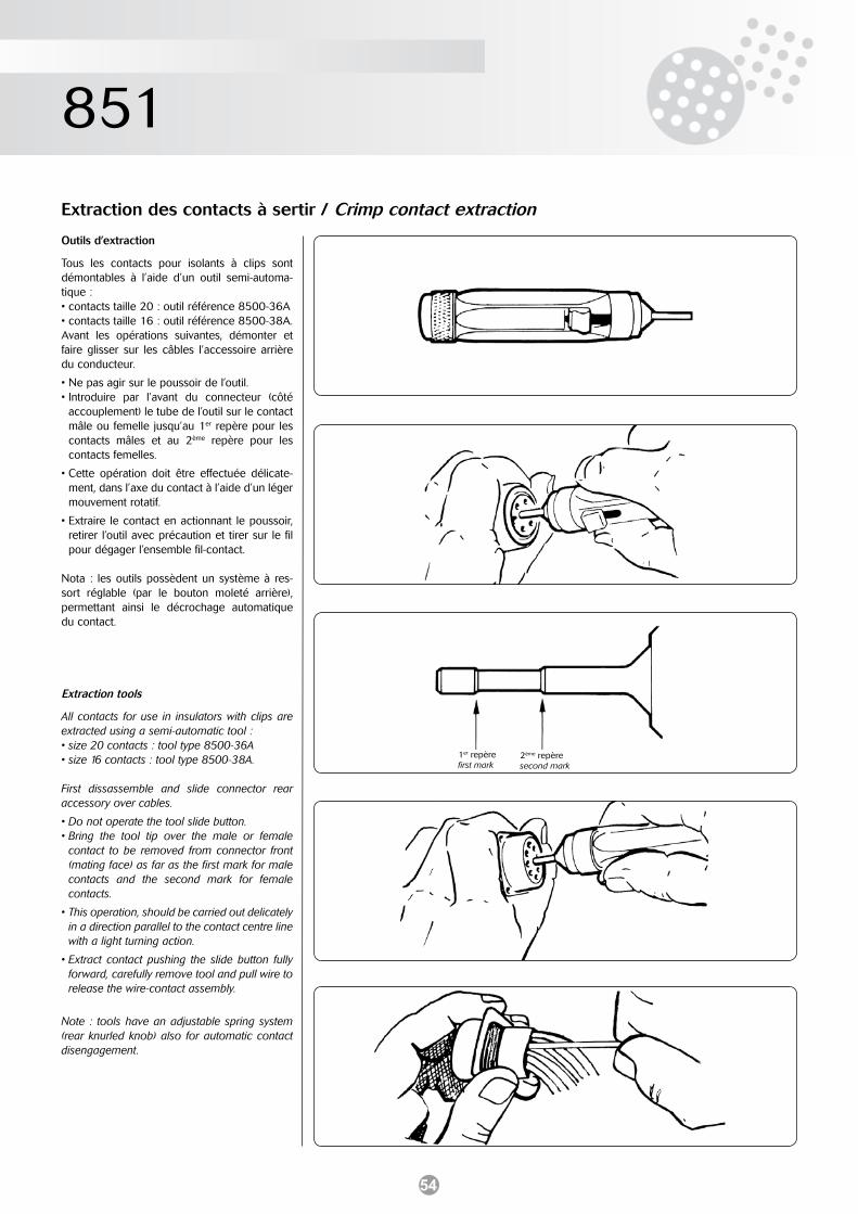
54
851
Extraction des contacts à sertir / Crimp contact extraction
Outils d’extraction
Tous les contacts pour isolants à clips sont démontables à l’aide d’un outil semi-automa-tique :• contacts taille 20 : outil référence 8500-36A• contacts taille 16 : outil référence 8500-38A.Avant les opérations suivantes, démonter et faire glisser sur les câbles l’accessoire arrière du conducteur.
• Ne pas agir sur le poussoir de l’outil.• Introduire par l’avant du connecteur (côté
accouplement) le tube de l’outil sur le contact mâle ou femelle jusqu’au 1er repère pour les contacts mâles et au 2ème repère pour les contacts femelles.
• Cette opération doit être effectuée délicate-ment, dans l’axe du contact à l’aide d’un léger mouvement rotatif.
• Extraire le contact en actionnant le poussoir, retirer l’outil avec précaution et tirer sur le fil pour dégager l’ensemble fil-contact.
Nota : les outils possèdent un système à res-sort réglable (par le bouton moleté arrière), permettant ainsi le décrochage automatique du contact.
Extraction tools
All contacts for use in insulators with clips are extracted using a semi-automatic tool :• size 20 contacts : tool type 8500-36A• size 16 contacts : tool type 8500-38A.
First dissassemble and slide connector rear accessory over cables.
• Do not operate the tool slide button.• Bring the tool tip over the male or female
contact to be removed from connector front (mating face) as far as the first mark for male contacts and the second mark for female contacts.
• This operation, should be carried out delicately in a direction parallel to the contact centre line with a light turning action.
• Extract contact pushing the slide button fully forward, carefully remove tool and pull wire to release the wire-contact assembly.
Note : tools have an adjustable spring system (rear knurled knob) also for automatic contact disengagement.
1er repèrefirst mark
2ème repèresecond mark
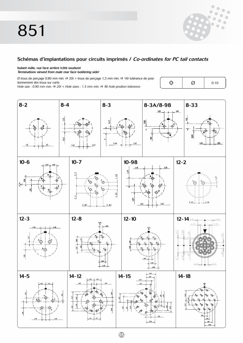
55
851
Schémas d’implantations pour circuits imprimés / Co-ordinates for PC tail contacts
Isolant mâle, vue face arrière (côté soudure)Terminations viewed from male rear face (soldering side)
Ø trous de perçage 0,90 mm min. (# 20) + trous de perçage 1,3 mm min. (# 16) tolérance de posi-tionnement des trous sur carteHole size : 0.90 mm min. (# 20) + Hole sizes : 1.3 mm min. (# 16) hole position tolerance.
O Ø 0.10
14-5
12-1012-812-3
14-1814-1514-12
12-210-9810-710-6
8-3A/8-988-38-48-2 8-33
12-14
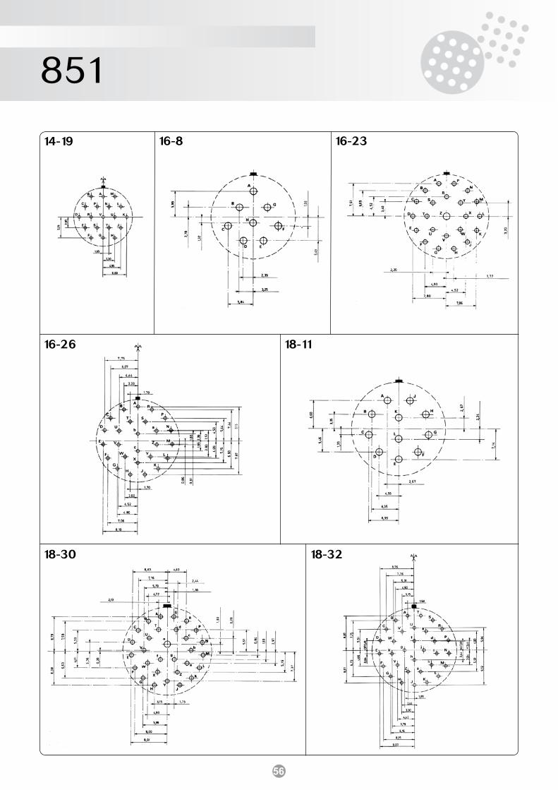
56
851
16-8 16-23
16-26 18-11
14-19
18-3218-30

57
851
20-16 20-24
20-25 20-27
20-39 20-41
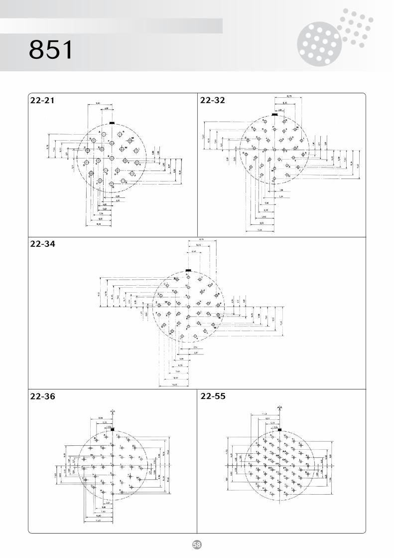
58
851
22-21 22-32
22-34
22-5522-36
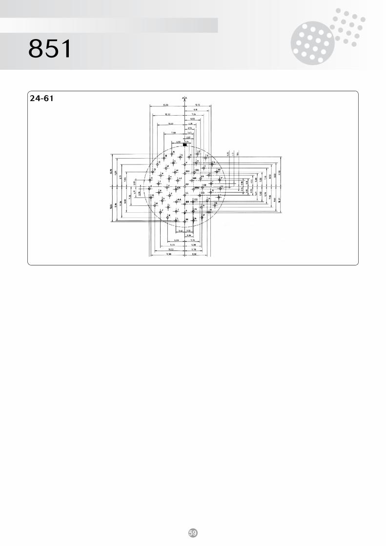
59
851
24-61
60
851
Prise largable push-pull / Push-pull locking plugCaractéristiques générales • Verrouillage : en poussant sur la bague• Déverrouillage : par traction sur la tirette de largage• Montage : sur toutes les embases 851• Arrangements et contacts à sertir et à souder : (voir pages 10 et
14/15)• Autres caractéristiques : (voir page 9)
Racine / Basic series version à sertir - crimp version 856 version à souder - solder version 856
0606
RE
• •• •
• •• •
PP
••
5050
• •• •
Type de boîtier / Shell type06 08
Type de raccord / Backshell typeR/E RC/EC RA/A RP/P RT/TRM/M *RT/*T RC/EC
Taille de boîtier / Shell size8 - 10 - 12 - 14 - 16 - 18 - 20 - 22 - 24
Arrangements / Contact layoutsVoir tableau des arrangements page 14/15 - See table page 14/15
Type de contact/ Contact typeP = mâle / male - S = femelle / female
Positionnement / OrientationNormal (n’apparaît pas dans la référence) w, x, y, z - voir tableau page 16Normal (not included in part number) w, x, y, z - see table page 16
Indice obligatoire / Obligatory suffix
Spécification / Specification07
08
09
General characteristics • Locking : by pushing on the coupling nut• Unlocking : by pulling a lanyard• Mounted : on all 851 receptacles• Layouts and crimp solder contacts : (see pages 10 and 14/15)• Other characteristics : (see page 9)
Références / Ordering information
fiche droite - plug for use with straight backshellfiche coudée - plug for use with 90° backshell
raccord simple / backnutraccord droit à serre-câbles / straight cable clampraccord droit intermédiaire / straight adaptorraccord droit pour potting / straight backshell for pottingraccord droit pour gaine thermorétractable / straight backshell for heatshrink sleevingraccord droit démontable pour gaine thermorétractablestraight removable backshell for heatshrink sleevingspécification 38 ou/or 42: raccord droit démontable pour reprise de tresse et gaine thermo-rétractable / straight removable backshell for screen termination and heatshrink sleevingraccord coudé à serre-câbles / 90° cable clamp
protection cadmié vert olive (version à souder)olive-green cadmium plating (solder version)protection cadmié vert olive (version à sertir)olive green cadmium plating (crimp version)protection cadmié blanc (version à sertir et à souder)white cadmium plating (crimp and solder version)
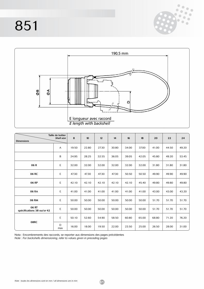
61
851
Taille de boîtierShell size
Dimensions8 10 12 14 16 18 20 22 24
A 19.50 22.80 27.30 30.80 34.00 37.00 41.00 44.50 49.20
B 24.95 28.25 32.55 36.05 39.05 42.05 45.80 49.20 53.45
06 R E 32.00 32.00 32.00 32.00 32.00 32.00 31.80 31.80 31.80
06 RC E 47.30 47.30 47.30 47.30 50.50 50.50 49.90 49.90 49.90
06 RP E 42.10 42.10 42.10 42.10 42.10 45.40 49.80 49.80 49.80
06 RA E 41.00 41.00 41.00 41.00 41.00 41.00 43.00 43.00 43.20
06 RM E 50.00 50.00 50.00 50.00 50.00 50.00 51.70 51.70 51.70
06 RTspécifications 38 ou/or 42
E 50.00 50.00 50.00 50.00 50.00 50.00 51.70 51.70 51.70
08RC
E 50.10 52.60 54.90 58.50 60.80 65.00 68.80 71.20 76.20
D max
16.00 18.00 19.50 22.00 23.50 25.00 26.50 28.00 31.00
Nota : Encombrements des raccords, se reporter aux dimensions des pages précédentesNote : For backshells dimensioning, refer to values given in preceding pages
Note : toutes les dimensions sont en mm / all dimensions are in mm
62
851
Connecteurs filtres 8F51 / 8F51 filter connectorsGénéralités Ces connecteurs sont dérivés des spécifications standards MIL-DTL-26482 G série 1 - NFC 93422 (HE 301 B) - VG 95328.
Ils sont interchangeables en fixation et intermariables avec les connecteurs standards.
Différents types de filtres peuvent équiper ces connecteurs et per-mettent ainsi de supprimer les interférences RFI/EMI dans différentes gammes de fréquences.
L’utilisation de ces connecteurs à filtres performants incorporés offre les avantages suivants :
• Filtrage efficace des parasites à l’entrée ou à la sortie d’un équipe-ment électronique,
• Ecran de blindage du coffret conservé,• Encombrement et coût plus réduit par rapport à l’utilisation de filtres
individuels câblés à l’arrière du connecteur,• Choix de 4 types de contacts standards - merci de nous consulter pour tout autre valeur de capacitance et type de filtre,• Possibilité de mixage de filtres dans le même arrangement : contacts
filtrés, non filtrés et liés à la masse.
La version adaptateur, également disponible, permet d’équiper sim-plement les systèmes existants non filtrés.
Caractéristiques électriques • Intensité max. par contact 7.5 A (#20); 13 A (#16)• Tension max. de service 200 Vdc / 120 Vac• Types de filtre standard C, Pi• Valeur de capacitance typ. de 500 pF à 200 nF• Performance filtre Jusqu’à -60dB / -80dB
Consulter pour ce produit notre département CONNECTEURS FILTRES.
General information These connectors are derived from standard specifications MIL-DTL-26482 G series 1 - NFC 93422 (HE 301 B) - VG 95328.
They are intermountable and intermateable with standard connectors.
Different types of filters may be fitted in these connectors to eliminate RFI/EMI in different frequency ranges.
Using built-in High Performance EMI filters offers the following advan-tages :
• Efficient filtering on interferences at electronic equipment input or output,
• Case screen-shielding efficiency is maintained,• Cost and volume saving as compared with the use of discrete filters
wired down the line,• 4 types of standard filters are available - Please consult us for other capacitance and filter types,• Combinations of mixed filter in the same layout: filtered, non-filtered
and grounded contacts available.
An adaptor version is also a simple technique to equip existing sys-tems which do not incorporate filters.
Electrical characteristics • Max. current rating per contact 7.5 A (#20); 13 A (#16)• Max. operating voltage 200 Vdc / 120 Vac• Standard filter types C, Pi• Capacitance range typically 500 pF - 200 nF• Filter performance up to -60dB / -80dB
For this product, consult our FILTER CONNECTOR department.
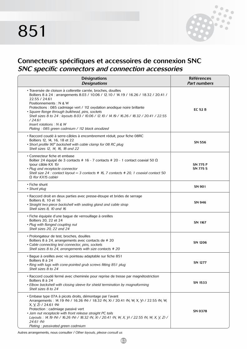
63
851
Connecteurs spécifiques et accessoires de connexion SNCSNC specific connectors and connection accessories
DésignationsDesignations
RéférencesPart numbers
• Traversée de cloison à collerette carrée, broches, douilles Boîtiers 8 à 24 : arrangements 8.03 / 10.06 / 12.10 / 14.19 / 16.26 / 18.32 / 20.41 / 22.55 / 24.61 Positionnements : N & W Protections : 085 cadmiage vert / 112 oxydation anodique noire brillante• Square flange through bulkhead, pins, sockets Shell sizes 8 to 24 : layouts 8.03 / 10.06 / 12.10 / 14.19 / 16.26 / 18.32 / 20.41 / 22.55 / 24.61 Insert rotations : N & W Plating : 085 green cadmium / 112 black anodized
EC 52 B
• Raccord coudé à serre-câbles à encombrement réduit, pour fiche 08RC Boîtiers 12, 14, 16, 18 et 22• Short profile 90° backshell with cable clamp for 08 RC plug Shell sizes 12, 14, 16, 18 and 22
SN 556
• Connecteur fiche et embase Boîtier 24 équipé de 3 contacts # 16 - 7 contacts # 20 - 1 contact coaxial 50 Ω (pour câble KX 15)• Plug and receptacle connector Shell size 24 : contact layout = 3 contacts # 16, 7 contacts # 20, 1 coaxial contact 50 Ω (for KX15 cable)
SN 775 PSN 775 S
• Fiche shunt• Shunt plug
SN 901
• Raccord droit en deux parties avec presse-étoupe et brides de serrage Boîtiers 8, 10 et 16• Straight two-piece backshell with sealing gland and cable strap Shell sizes 8, 10 and 16
SN 946
• Fiche équipée d’une bague de verrouillage à oreilles Boîtiers 20, 22 et 24• Plug with flanged coupling nut Shell sizes 20, 22 and 24
SN 1167
• Prolongateur de test, broches, douilles Boîtiers 8 à 24, arrangements avec contacts de # 20• Cable connecting test connector, pins, sockets Shell sizes 8 to 24, arrangements with size contacts # 20
SN 1206
• Bague à oreilles avec vis pointeau adaptable sur fiche 851 Boîtiers 8 à 24• Ring with lugs with cone-pointed grub screws fitting 851 plug Shell sizes 8 to 24
SN 1277
• Raccord coudé fermé avec cheminée pour reprise de tresse par magnétostriction Boîtiers 8 à 24• Elbow backshell with closing sleeve for shield termination by magnaforming Shell sizes 8 to 24
SN 1533
• Embase type 07A à picots droits, démontage par l’avant Arrangements : 14.19 (N) / 16.26 (N) / 18.32 (N, X) / 20.41 (N, W, X, Y) / 22.55 (N, W, X, Y, Z) / 24.61 (N) Protection : cadmiage passivé vert• Jam nut receptacle with front release straight PC tails Layouts : 14.19 (N) / 16.26 (N) / 18.32 (N, X) / 20.41 (N, W, X, Y) / 22.55 (N, W, X, Y, Z) / 24.61 (N) Plating : passivated green cadmium
SN 0378
Autres arrangements, nous consulter / Other layouts, please consult us
64
Notes / Notes
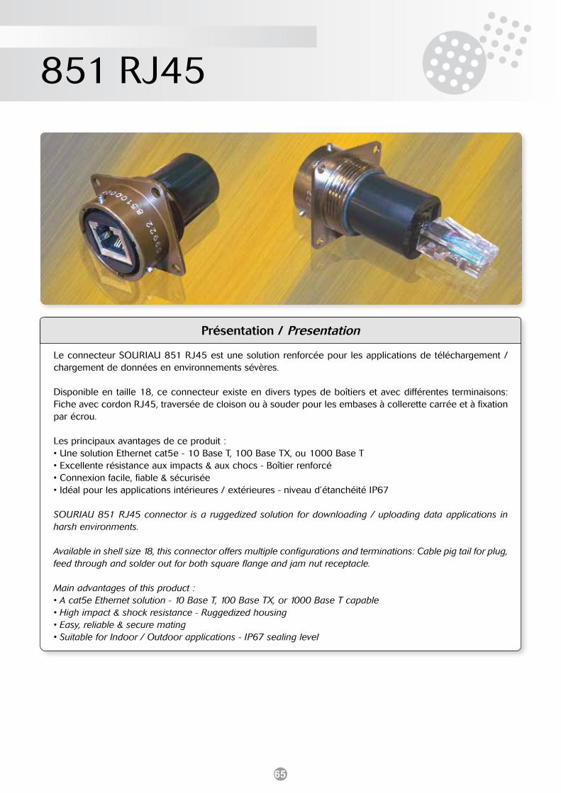
65
851 RJ45
Présentation / Presentation
Le connecteur SOURIAU 851 RJ45 est une solution renforcée pour les applications de téléchargement / chargement de données en environnements sévères.
Disponible en taille 18, ce connecteur existe en divers types de boîtiers et avec différentes terminaisons: Fiche avec cordon RJ45, traversée de cloison ou à souder pour les embases à collerette carrée et à fixation par écrou.
Les principaux avantages de ce produit :• Une solution Ethernet cat5e - 10 Base T, 100 Base TX, ou 1000 Base T• Excellente résistance aux impacts & aux chocs - Boîtier renforcé• Connexion facile, fiable & sécurisée• Idéal pour les applications intérieures / extérieures - niveau d’étanchéité IP67
SOURIAU 851 RJ45 connector is a ruggedized solution for downloading / uploading data applications in harsh environments.
Available in shell size 18, this connector offers multiple configurations and terminations: Cable pig tail for plug, feed through and solder out for both square flange and jam nut receptacle.
Main advantages of this product :• A cat5e Ethernet solution - 10 Base T, 100 Base TX, or 1000 Base T capable• High impact & shock resistance - Ruggedized housing• Easy, reliable & secure mating• Suitable for Indoor / Outdoor applications - IP67 sealing level
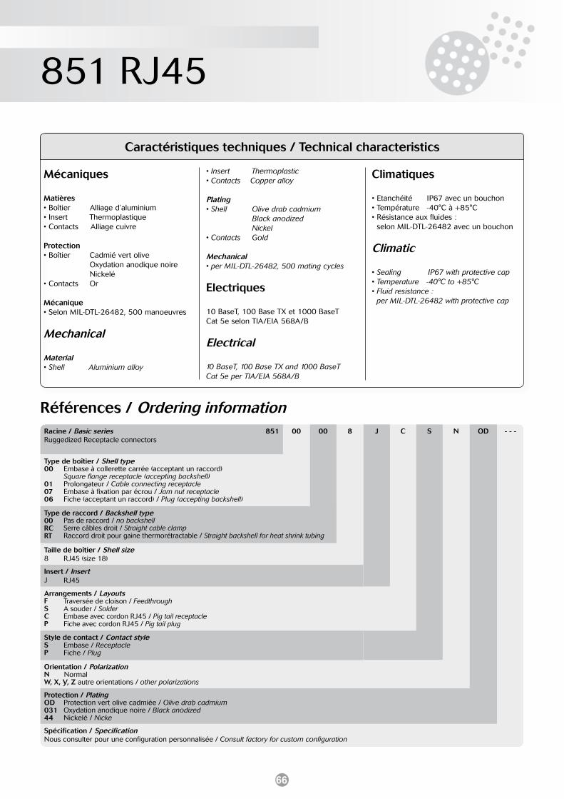
66
851 RJ45
Mécaniques
Matières• Boîtier Alliage d’aluminium• Insert Thermoplastique• Contacts Alliage cuivre
Protection• Boîtier Cadmié vert olive Oxydation anodique noire Nickelé • Contacts Or
Mécanique• Selon MIL-DTL-26482, 500 manoeuvres
Mechanical
Material• Shell Aluminium alloy
• Insert Thermoplastic• Contacts Copper alloy
Plating• Shell Olive drab cadmium Black anodized Nickel • Contacts Gold
Mechanical• per MIL-DTL-26482, 500 mating cycles
Electriques
10 BaseT, 100 Base TX et 1000 BaseTCat 5e selon TIA/EIA 568A/B
Electrical
10 BaseT, 100 Base TX and 1000 BaseTCat 5e per TIA/EIA 568A/B
Climatiques
• Etanchéité IP67 avec un bouchon• Température -40°C à +85°C• Résistance aux fluides : selon MIL-DTL-26482 avec un bouchon
Climatic
• Sealing IP67 with protective cap• Temperature -40°C to +85°C• Fluid resistance : per MIL-DTL-26482 with protective cap
Caractéristiques techniques / Technical characteristics
Références / Ordering informationRacine / Basic series 851Ruggedized Receptacle connectors
00 00 8 J C S N OD - - -
Type de boîtier / Shell type00
010706
Type de raccord / Backshell type00RCRT
Taille de boîtier / Shell size8
Insert / InsertJ
Arrangements / LayoutsFSCP
Style de contact / Contact styleSP
Orientation / PolarizationN NormalW, X, Y, Z autre orientations / other polarizations
Protection / PlatingOD03144
Spécification / SpecificationNous consulter pour une configuration personnalisée / Consult factory for custom configuration
Embase à collerette carrée (acceptant un raccord)Square flange receptacle (accepting backshell)Prolongateur / Cable connecting receptacleEmbase à fixation par écrou / Jam nut receptacleFiche (acceptant un raccord) / Plug (accepting backshell)
Pas de raccord / no backshellSerre câbles droit / Straight cable clampRaccord droit pour gaine thermorétractable / Straight backshell for heat shrink tubing
RJ45 (size 18)
RJ45
Traversée de cloison / FeedthroughA souder / SolderEmbase avec cordon RJ45 / Pig tail receptacleFiche avec cordon RJ45 / Pig tail plug
Embase / ReceptacleFiche / Plug
Protection vert olive cadmiée / Olive drab cadmiumOxydation anodique noire / Black anodizedNickelé / Nicke
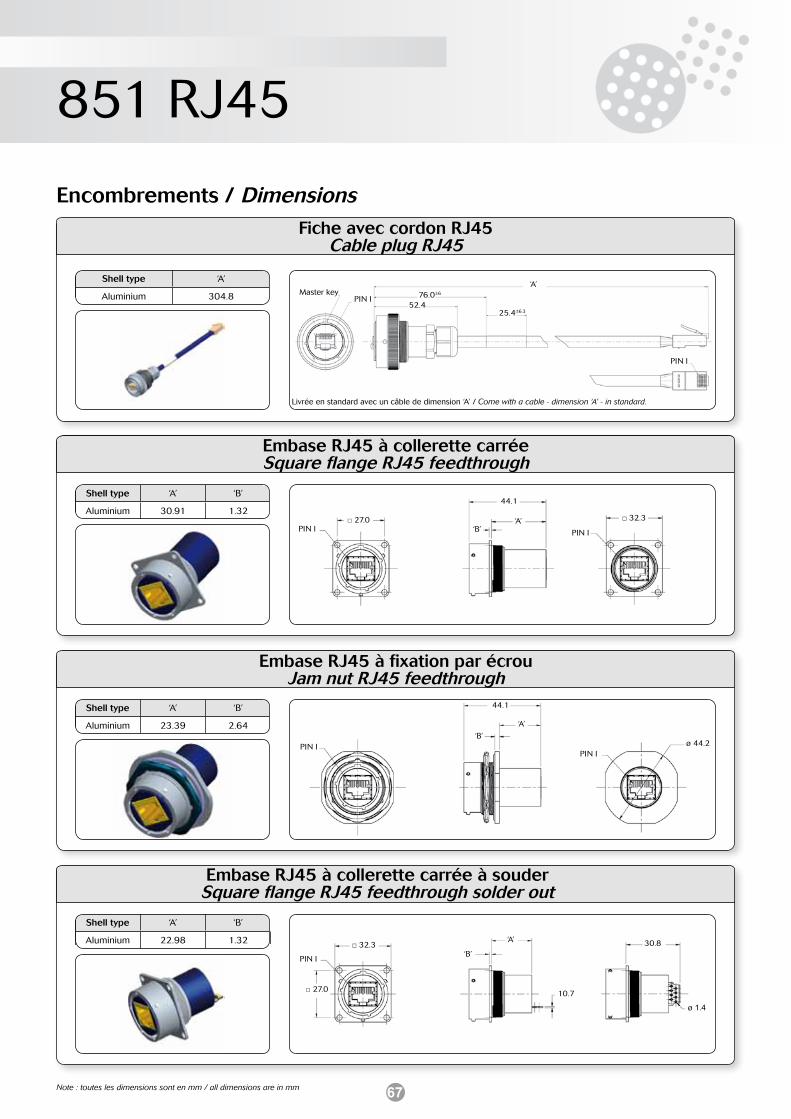
67
851 RJ45
Embase RJ45 à collerette carrée à souderSquare flange RJ45 feedthrough solder out
Shell type ‘A’ ‘B’
Aluminium 22.98 1.32
Encombrements / Dimensions
Embase RJ45 à collerette carrée Square flange RJ45 feedthrough
Shell type ‘A’ ‘B’
Aluminium 30.91 1.32
Embase RJ45 à fixation par écrou Jam nut RJ45 feedthrough
Shell type ‘A’ ‘B’
Aluminium 23.39 2.64
PIN I 27.0
44.1
‘A’‘B’ PIN I
32.3
PIN I
44.1
‘A’
‘B’
PIN Iø 44.2
PIN I
27.0 10.7
‘A’
‘B’30.8
ø 1.4
32.3
Note : toutes les dimensions sont en mm / all dimensions are in mm
Fiche avec cordon RJ45 Cable plug RJ45
Shell type ‘A’
Aluminium 304.8 PIN I 76.0±6
‘A’
52.4
PIN I
25.4±6.3
Master key
Livrée en standard avec un câble de dimension ‘A’ / Come with a cable - dimension ‘A’ - in standard.
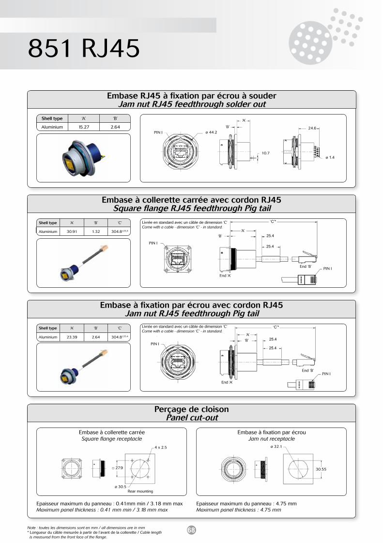
68
851 RJ45
Embase à collerette carrée avec cordon RJ45Square flange RJ45 feedthrough Pig tail
Embase à fixation par écrou avec cordon RJ45 Jam nut RJ45 feedthrough Pig tail
Shell type ‘A’ ‘B’ ‘C’
Aluminium 30.91 1.32 304.8±25.4
Shell type ‘A’ ‘B’ ‘C’
Aluminium 23.39 2.64 304.8±25.4
PIN I
25.4‘A’
‘B’
End ‘B’ PIN I
‘C’*
25.4
End ‘A’
PIN I25.4
‘A’
‘B’
End ‘B’PIN I
‘C’*
25.4
End ‘A’
Note : toutes les dimensions sont en mm / all dimensions are in mm* Longueur du câble mesurée à partir de l’avant de la collerette / Cable length is measured from the front face of the flange.
Embase RJ45 à fixation par écrou à souder Jam nut RJ45 feedthrough solder out
Shell type ‘A’ ‘B’
Aluminium 15.27 2.64PIN I
10.7
‘A’
‘B’ 24.6ø 44.2
ø 1.4
Livrée en standard avec un câble de dimension ‘C’ Come with a cable - dimension ‘C’ - in standard.
Livrée en standard avec un câble de dimension ‘C’ Come with a cable - dimension ‘C’ - in standard.
Perçage de cloison Panel cut-out
Embase à collerette carréeSquare flange receptacle
Embase à fixation par écrouJam nut receptacle
Epaisseur maximum du panneau : 4.75 mmMaximum panel thickness : 4.75 mm
Epaisseur maximum du panneau : 0.41mm min / 3.18 mm maxMaximum panel thickness : 0.41 mm min / 3.18 mm max
ø 30.5
27.9
4 x 2.5
Rear mounting
ø 32.1
30.55
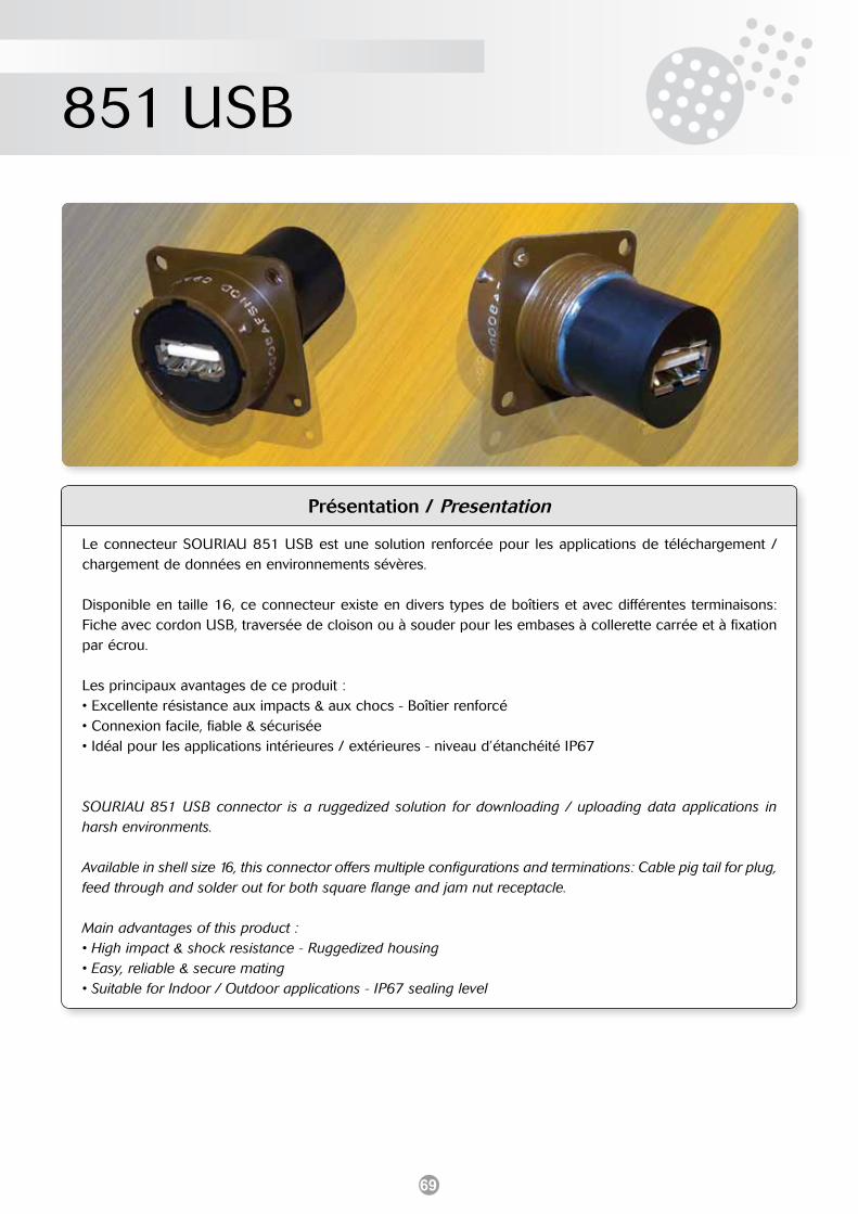
69
851 USB
Présentation / Presentation
Le connecteur SOURIAU 851 USB est une solution renforcée pour les applications de téléchargement / chargement de données en environnements sévères.
Disponible en taille 16, ce connecteur existe en divers types de boîtiers et avec différentes terminaisons: Fiche avec cordon USB, traversée de cloison ou à souder pour les embases à collerette carrée et à fixation par écrou.
Les principaux avantages de ce produit :• Excellente résistance aux impacts & aux chocs - Boîtier renforcé• Connexion facile, fiable & sécurisée• Idéal pour les applications intérieures / extérieures - niveau d’étanchéité IP67
SOURIAU 851 USB connector is a ruggedized solution for downloading / uploading data applications in harsh environments.
Available in shell size 16, this connector offers multiple configurations and terminations: Cable pig tail for plug, feed through and solder out for both square flange and jam nut receptacle.
Main advantages of this product :• High impact & shock resistance - Ruggedized housing• Easy, reliable & secure mating• Suitable for Indoor / Outdoor applications - IP67 sealing level
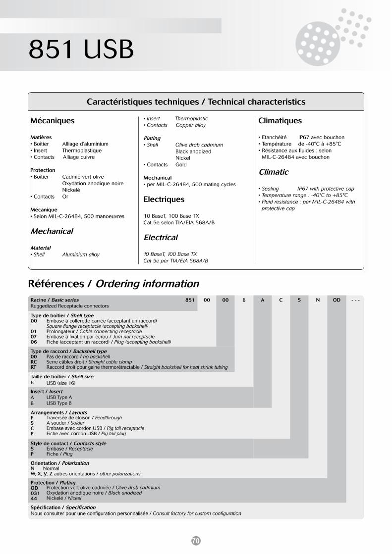
70
851 USB
Mécaniques
Matières• Boîtier Alliage d’aluminium• Insert Thermoplastique• Contacts Alliage cuivre
Protection• Boîtier Cadmié vert olive Oxydation anodique noire Nickelé • Contacts Or
Mécanique• Selon MIL-C-26484, 500 manoeuvres
Mechanical
Material• Shell Aluminium alloy
• Insert Thermoplastic• Contacts Copper alloy
Plating• Shell Olive drab cadmium Black anodized Nickel • Contacts Gold
Mechanical• per MIL-C-26484, 500 mating cycles
Electriques
10 BaseT, 100 Base TX Cat 5e selon TIA/EIA 568A/B
Electrical
10 BaseT, 100 Base TX Cat 5e per TIA/EIA 568A/B
Climatiques
• Etanchéité IP67 avec bouchon• Température de -40°C à +85°C• Résistance aux fluides : selon MIL-C-26484 avec bouchon
Climatic
• Sealing IP67 with protective cap• Temperature range : -40°C to +85°C• Fluid resistance : per MIL-C-26484 with protective cap
Caractéristiques techniques / Technical characteristics
Références / Ordering informationRacine / Basic series 851Ruggedized Receptacle connectors
00 00 6 A C S N OD - - -
Type de boîtier / Shell type00
010706
Type de raccord / Backshell type00RCRT
Taille de boîtier / Shell size6
Insert / InsertA B
Arrangements / LayoutsFSCP
Style de contact / Contacts styleSP
Orientation / PolarizationN NormalW, X, Y, Z autres orientations / other polarizations
Protection / PlatingOD03144
Spécification / SpecificationNous consulter pour une configuration personnalisée / Consult factory for custom configuration
Embase à collerette carrée (acceptant un raccord)Square flange receptacle (accepting backshell)Prolongateur / Cable connecting receptacleEmbase à fixation par écrou / Jam nut receptacleFiche (acceptant un raccord) / Plug (accepting backshell)
Pas de raccord / no backshellSerre câbles droit / Straight cable clampRaccord droit pour gaine thermorétractable / Straight backshell for heat shrink tubing
USB (size 16)
USB Type AUSB Type B
Traversée de cloison / FeedthroughA souder / SolderEmbase avec cordon USB / Pig tail receptacleFiche avec cordon USB / Pig tail plug
Embase / ReceptacleFiche / Plug
Protection vert olive cadmiée / Olive drab cadmiumOxydation anodique noire / Black anodizedNickelé / Nickel
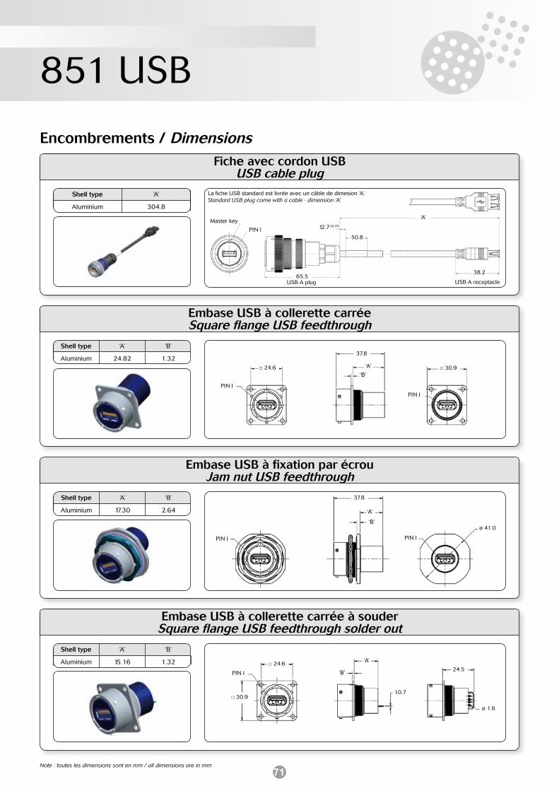
71
851 USB
Embase USB à collerette carrée à souderSquare flange USB feedthrough solder out
Shell type ‘A’ ‘B’
Aluminium 15.16 1.32
Encombrements / Dimensions
Embase USB à collerette carrée Square flange USB feedthrough
Shell type ‘A’ ‘B’
Aluminium 24.82 1.32
Embase USB à fixation par écrou Jam nut USB feedthrough
Shell type ‘A’ ‘B’
Aluminium 17.30 2.64
PIN I
24.6
37.8
‘A’‘B’
30.9
PIN I
PIN I
37.8
‘A’
‘B’ø 41.0
PIN I
PIN I
30.910.7
‘A’
‘B’ 24.5
ø 1.6
24.6
Note : toutes les dimensions sont en mm / all dimensions are in mm
Fiche avec cordon USB USB cable plug
Shell type ‘A’
Aluminium 304.8
PIN I 12.7±6.35
‘A’
38.2
50.8
Master key
La fiche USB standard est livrée avec un câble de dimesion ‘A’. Standard USB plug come with a cable - dimension ‘A’.
65.5USB-A receptacleUSB-A plug
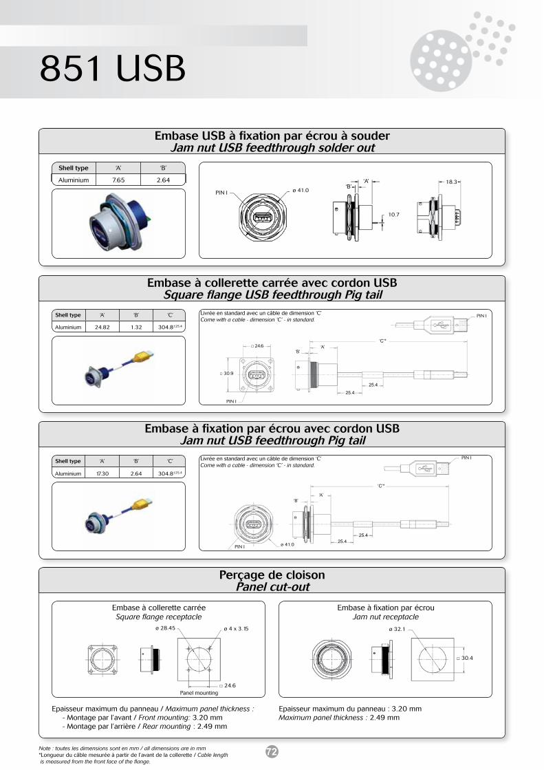
72
851 USB
Embase USB à fixation par écrou à souderJam nut USB feedthrough solder out
Shell type ‘A’ ‘B’
Aluminium 7.65 2.64
PIN I ø 41.0
‘A’‘B’
18.3
10.7
Embase à collerette carrée avec cordon USBSquare flange USB feedthrough Pig tail
Embase à fixation par écrou avec cordon USBJam nut USB feedthrough Pig tail
Shell type ‘A’ ‘B’ ‘C’
Aluminium 24.82 1.32 304.8±25.4
Shell type ‘A’ ‘B’ ‘C’
Aluminium 17.30 2.64 304.8±25.4
PIN I
25.4
‘A’‘B’
PIN I
‘C’*
25.4
30.9
24.6
PIN I
25.4
‘A’‘B’
PIN I
‘C’*
25.4ø 41.0
Note : toutes les dimensions sont en mm / all dimensions are in mm*Longueur du câble mesurée à partir de l’avant de la collerette / Cable length is measured from the front face of the flange.
Perçage de cloison Panel cut-out
Embase à collerette carréeSquare flange receptacle
Embase à fixation par écrouJam nut receptacle
Epaisseur maximum du panneau / Maximum panel thickness : - Montage par l’avant / Front mounting: 3.20 mm - Montage par l’arrière / Rear mounting : 2.49 mm
Epaisseur maximum du panneau : 3.20 mm Maximum panel thickness : 2.49 mm
ø 28.45 ø 4 x 3.15
24.6Panel mounting
ø 32.1
30.4
Livrée en standard avec un câble de dimension ‘C’ Come with a cable - dimension ‘C’ - in standard.
Livrée en standard avec un câble de dimension ‘C’ Come with a cable - dimension ‘C’ - in standard.
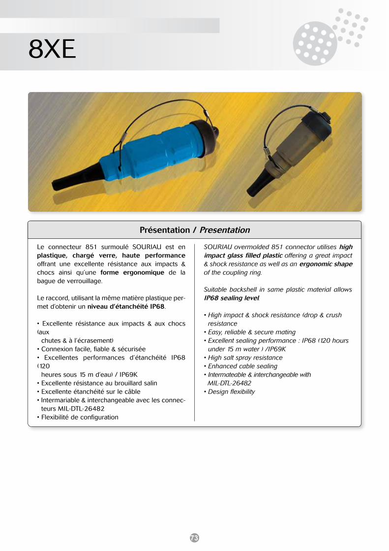
73
8XE
Présentation / Presentation
SOURIAU overmolded 851 connector utilises high impact glass filled plastic offering a great impact & shock resistance as well as an ergonomic shape of the coupling ring.
Suitable backshell in same plastic material allows IP68 sealing level.
• High impact & shock resistance (drop & crush resistance• Easy, reliable & secure mating• Excellent sealing performance : IP68 (120 hours under 15 m water ) /IP69K• High salt spray resistance• Enhanced cable sealing• Intermateable & interchangeable with MIL-DTL-26482• Design flexibility
Le connecteur 851 surmoulé SOURIAU est en plastique, chargé verre, haute performance offrant une excellente résistance aux impacts & chocs ainsi qu’une forme ergonomique de la bague de verrouillage.
Le raccord, utilisant la même matière plastique per-met d’obtenir un niveau d’étanchéité IP68.
• Excellente résistance aux impacts & aux chocs (aux chutes & à l’écrasement)• Connexion facile, fiable & sécurisée• Excellentes performances d’étanchéité IP68 (120 heures sous 15 m d’eau) / IP69K• Excellente résistance au brouillard salin• Excellente étanchéité sur le câble• Intermariable & interchangeable avec les connec- teurs MIL-DTL-26482• Flexibilité de configuration
74
8XE
Mécaniques
• Endurance • Boîtier • Insert • Contacts • Enveloppe extérieure Plastique chargé verre haute résistance• Joint bague de verrouillage Teflon sur silicone
Mechanical
• Durability• Shell• Insert• Contacts• Housing• Coupling ring seal
Electriques
• Résistance d’isolement 5000 MΩ• Tension de tenue 2300 V• Résistance contact 3 MΩ• Intensité admissible par contact Taille16 : 13 A / Taille 20 : 7.5 A
Electrical
• Insulation resistance 5000 MΩ• Dielectric withstanding voltage 2300 V• Contact resistance 3 MΩ• Current rating per contact Size 16: 13 A / Size 20: 7.5 A
Climatiques
• Température d’utilisation -55°C à +125°C• Etanchéité Interface IP68 (jusqu’à 120 heures sous 15 mètres d’eau)• Résistance aux produits chimiques selon MIL-DTL-26482 Série 1
Climatic
• Working temperature -55°C to +125°C• Sealing Interfacial IP68 (up to 120 hours under 15 meters of water)• Resistance to chemicals in accordance with MIL-DTL-26482 Series 1
Acceptance câbles
• Câble Gauge 14 max.• Diamètre gaine extérieure: Toutes tailles jusqu’à 11.17 mm
Cable acceptance
• Primaries wire Gauge 14 max.• Outer jacket all popular sizes up to 11.17 mm
500 manoeuvres min.Alliage d’aluminium - anodisé durElastomer néoprèneAlliage de cuivre - protection or
500 mating min.Aluminium alloy - hard anodizedNeoprene elastomerCopper alloy with gold platingHigh impact glass filled plastic Teflon over silicone
Références / Ordering informationRacine / Basic series 8XEConnecteur pour environnment EXTREME / connector for EXTREME environment
06 - 16 8 P - BL V8 - - -
Type de boîtier / Connector type01 Prolongateur / Cable connecting receptacle06 Fiche / Plug
Type de contact / Contact typePas de digit / No digit à souder / to solderR à sertir / to crimp
Taille de boîtier / Shell size10, 12, 14, 16, 20, 22
Arrangements / LayoutsVoir page suivante / See next page
Sexe du contact / Contact genderP Mâle / maleS Femelle / female
Orientations / Insert orientationsPas de digit / No digit Normal (n’apparaît pas dans lé référence) / Standard (not included in part number)W, X, Y, Z autres orientations / other orientations
Couleur / ColorPas de digit / No digit Gris / Mink (standard) BL Bleu / Blue YE Jaune / Yellow RE Rouge / RedAutres couleurs disponibles / Others available
Specification / Design variationV8 Boîtier renforcé en taille 16 & 20 / ruggedized shells in size 16 & 20AA Boîtier inox renforcé en taille 16 & 20 (Ø câble 8 mm) / ruggedized stainless steel shells in size 16 & 20 (cable Ø 8 mm)
Diamètre du câble / Cable diameterPersonnalisation possible / Custom available
Caractéristiques techniques / Technical characteristics
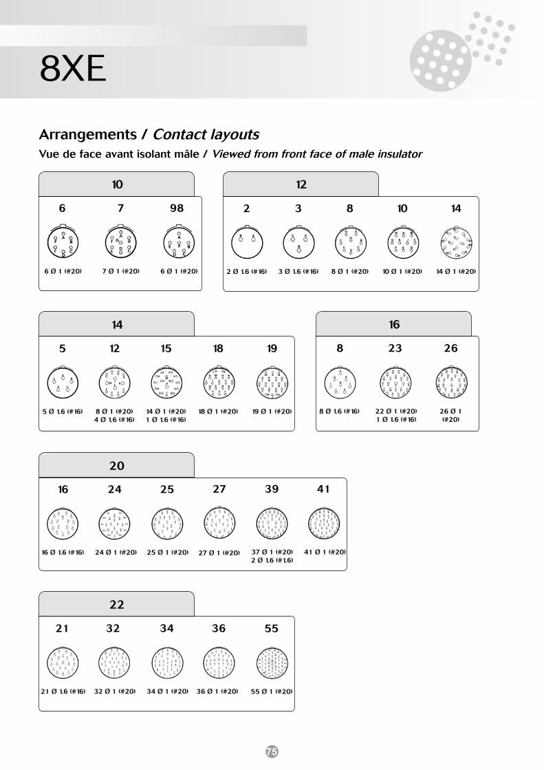
75
8XE
10
6
6 Ø 1 (#20)
7
7 Ø 1 (#20)
98
6 Ø 1 (#20)
12
3
3 Ø 1.6 (#16)
8
8 Ø 1 (#20)
10
10 Ø 1 (#20)
14
14 Ø 1 (#20)
2
2 Ø 1.6 (#16)
12
8 Ø 1 (#20) 4 Ø 1.6 (#16)
15
14 Ø 1 (#20) 1 Ø 1.6 (#16)
18
18 Ø 1 (#20)
19
19 Ø 1 (#20)
5
5 Ø 1.6 (#16)
16
8
8 Ø 1.6 (#16)
23
22 Ø 1 (#20)1 Ø 1.6 (#16)
26
26 Ø 1 (#20)
16
16 Ø 1.6 (#16)
39
37 Ø 1 (#20) 2 Ø 1.6 (#1.6)
41
41 Ø 1 (#20)
24
24 Ø 1 (#20)
25
25 Ø 1 (#20)
36
36 Ø 1 (#20)
55
55 Ø 1 (#20)
32
32 Ø 1 (#20)
34
34 Ø 1 (#20)
21
21 Ø 1.6 (#16)
27
27 Ø 1 (#20)
14
20
Arrangements / Contact layoutsVue de face avant isolant mâle / Viewed from front face of male insulator
22
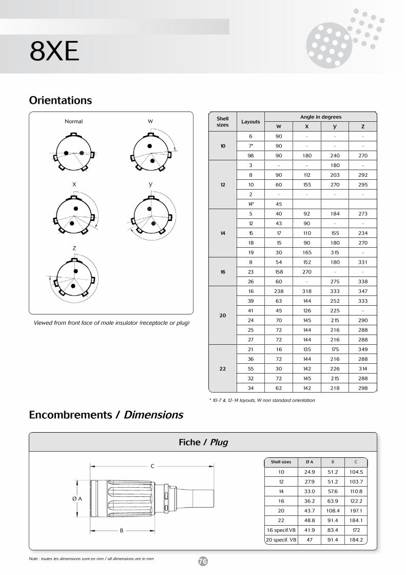
76
8XE
Note : toutes les dimensions sont en mm / all dimensions are in mm
Encombrements / Dimensions
Fiche / Plug
Shell sizes Ø A B C
10 24.9 51.2 104.5
12 27.9 51.2 103.7
14 33.0 57.6 110.8
16 36.2 63.9 122.2
20 43.7 108.4 197.1
22 48.8 91.4 184.1
16 specif.V8 41.9 83.4 172
20 specif. V8 47 91.4 184.2
Orientations
Viewed from front face of male insulator (receptacle or plug)
Shell sizes
LayoutsAngle in degrees
W X Y Z
10
6 90 - - -
7* 90 - - -
98 90 180 240 270
12
3 - - 180 -
8 90 112 203 292
10 60 155 270 295
2 - - - -
14* 45
14
5 40 92 184 273
12 43 90 - -
15 17 110 155 234
18 15 90 180 270
19 30 165 315 -
16
8 54 152 180 331
23 158 270 - -
26 60 - 275 338
20
16 238 318 333 347
39 63 144 252 333
41 45 126 225 -
24 70 145 215 290
25 72 144 216 288
27 72 144 216 288
22
21 16 135 175 349
36 72 144 216 288
55 30 142 226 314
32 72 145 215 288
34 62 142 218 298
Normal W
X Y
* 10-7 & 12-14 layouts, W non standard orientation
C
B
Ø A
Z
77
851
Protection non cadmiée Cadmium free plating
SOURIAU propose des connecteurs 851 avec une protection noire non cadmiée. Cette protection zinc-nickel a été dévelop-pée pour répondre aux nouvelles exigences en matière de res-pect de l’environnement (directive Européenne 76/769 EEC).
Raison :• Réduire le niveau de pollution par métaux lourds produit par
le cadmium
• Réduire les risques de santé engendrés par les produits cad-miés.
Caractéristiques :• Mécaniques - boîtiers : aluminium - protection : zinc-nickel
• Electriques - continuité électrique des boîtiers : ≤ 2,5 mΩ
• Climatiques - tenue au brouillard salin : 500 heures
Références :Exemples* :• Version à souder 851 00 E 8-3A P.54 protection zinc-nickel• Version à sertir 851 00 R 8-3A P.54 protection zinc-nickel
* Voir système de référence - page 11 (version à souder et à sertir) - page 13 (version à picots et connexions enroulées)
Cette protection est disponible pour les boîtiers de type :
- 00: embase à collerette carrée avec possibilité de raccord- 02: embase à collerette carrée sans possibilité de raccord- 07: embase à fixation par écrou avec possibilité de raccord- 07A: embase à fixation par écrou sans possibilité de raccord- 01: prolongateur- 06: fiche droite sans bague de blindage- 36: fiche droite avec bague de blindage
Raccords, nous consulter.
SOURIAU propose a 851 connector with cadmium free plating black. This zinc-nickel plating has been introduced in accor-dance with European Herth and Safety requirements (European directive 76/769 EEC).
Reason :• Reduction in level of heavy metal pollutants produced by
cadmium.
• Reduction in health associated with the corrosive by pro-ducts of cadmium.
Characteristics :• Mechanical - shell : aluminium alloy - plating : zinc-nickel
• Electrical - shell continuity : ≤ 2.5 mΩ
• Climatic - salt spray : 500 hours
Part numbers :Examples* :• Solder version 851 00 E 8-3A P.54 zinc-nickel plating• Crimp version 851 00 R 8-3A P.54 zinc-nickel plating
* See part numbers system - page 11 (solder and crimp version) - page 13 (straight PC tails and wire-wrap versions)
This plating is available for shell type :
- 00: square flange receptacle accepting backshells- 02: square flange receptacle not accepting backshells- 07: jam nut receptacle accepting backshells- 07A: jam nut receptacle not accepting backshells- 01: cable connecting receptacle- 06: plug for use without straight backshell- 36: screened plug for use with straight backshells
Backshells, please consult us.

78
Notes / Notes

IND
851C
A03
ENFR
W ©
SO
UR
IAU
- A
pril
2009
- A
ll in
form
atio
n in
this
doc
umen
t pre
sent
s on
ly g
ener
al p
artic
ular
s an
d sh
all n
ot fo
rm p
art o
f any
con
tract
. All
right
s re
serv
ed to
SO
UR
IAU
for c
hang
es w
ithou
t prio
r not
ifica
tion
or p
ublic
ann
ounc
emen
t. A
ny d
uplic
atio
n is
pro
hibi
ted,
unl
ess
appr
oved
in w
ritin
g.
www.souriau.comwww.souriau-industrial.comcontactindustry@souriau.com
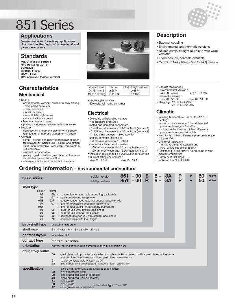
16
851 Series
specification - olive green cadmium plate (without specification)02 white cadmium plate29 black anodized (solder contacts)
031 black anodized (crimp contacts)44 nickel plate38 nickel plate backshell type T* and RT*42 olive green cadmium plate
obligatory suffix 50 gold plated crimp contacts - solder contacts size 20 - contacts with a gold plated active zone
and tin plated terminations - other gold plated terminations51 solder contacts gold plated size 2052 zinc cobalt olive green plated (contacts : idem specif. 50)
orientation normal (not included in part number) w, x, y, z, see table p 21
contact type P = male - S = female
contact layout see table p 20
shell size 8 - 10 - 12 - 14 - 16 - 18 - 20 - 22 - 24
backshell type see table next page
shell type solder crimp
00 00 - square flange receptacle accepting backshells01 01 - cable connecting receptacle
02E 02R - square flange receptacle not accepting backshells07 07 - jam nut receptacle accepting backshells
07A - jam nut receptacle not accepting backshells06 06 - plug for use with straight backshells08 08 - plug for use with 90° backshells36 36 - screened plug for use with straight backshells76 76 - screened plug with lock finger
ApplicationsFormer connector for military applications.Now used in the fields of professional andgeneral electronics.
Description• Bayonet coupling• Environmental and hermetic versions• Solder, crimp, straight spills and wire wrap
versions• Thermocouple contacts available• Cadmium free plating (Zinc Cobalt) version
• Contact resistance :- environmental version :
size 20 : 4 mΩ size 16 : 3 mΩ- hermetic version :
size 20 : 30 mΩ size 16 : 14 mΩ• Shielding : 70 dB to 5 MHz
40 dB to 100 MHz
Climatic• Working temperature : -55°C to +125°C• Sealing :
- crimp contact version, 1 bar differentialpressure, leakage ≤ 8 cm3/hr
- solder contact version, 2 bar differentialpressure, leakage ≤ 16 cm3/hr
• Hermiticity : 1 bar differential pressure leakage≤ 2,8 mm3/hr
• Chemical resistance :- to MIL-C 26482 G Series 1 and - NFC 93422-HE 301 B code A
• Resistance to salt spray : 48 hours at environ-mental temperature
• Damp heat : 21 days• Vibration : to NFC 20-616
Electrical• Dielectric withstanding voltage :
• at standard pressure : mated and unmated connectors- 1 500 Vrms between size 20 contacts (service 1)- 2 300 Vrms between size 16 contacts (service 2)- 1 500 Vrms between mixed size 20 and 16 contacts (service 1)• at reduced pressure (10 mbar) :connectors mated and unmated- 200 Vrms between size 20 contacts (service 1)- 300 Vrms between size 16 contacts (service 2)
• Insulation resistance : ≥ 5 000 MΩ under 500 Vdc• Current rating per contact :
size 20 : 7.5 A size 16 : 13 A
StandardsMIL-C 26482 G Series 1NFC 93422-He 301 BVG 95328BS 9522 F 0017GAM T1 listQPL approved (solder version)
Characteristics Mechanical• Shell :
• environmental version : aluminum alloy plating- olive green cadmium- black anodized- white cadmium- satin finish bright nickel- zinc cobalt (olive green)
• hermetic version : steel• plating : - iridescent yellow cadmium, nickel
• Insulator :- front section : neoprene elastomer (85 shore)- rear section : neoprene elastomer (40 shore)
• Contact :- crimp : inserted and removed from rear of insula-
tor retained by metallic clip ; solder and straightspills : non removable ; wire wrap : removable ornot removable
- material : copper alloy- plating : gold overall or gold plated active zone
and tin/lead plated termination- min retention force of contacts in insulator
basic series solder version 851 - 00 E 8 - 3A P • 50 •••crimp version 851 - 00 R 8 - 3A P • 50 •••
contact size20 (Ø 1 mm)
16 (Ø 1.6 mm)
crimp≥ 68 N≥ 113 N
solder straight spill ww≥ 68 N≥ 113 N
• Mechanical endurance :500 cycles (full mating-unmating)
Ordering information - Environmental connectors
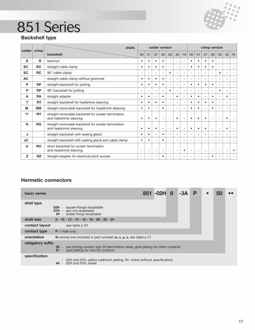
17
851 Series
specification - 02H and 07H, yellow cadmium plating. IH, nickel (without specification)
44 - 02H and 07H, nickel
obligatory suffix 50 - pre-tinning contact size 20 (termination area), gold plating for other contacts51 - gold plating for size 20 contacts
orientation N normal (not included in part number) w, x, y, z, see table p 21
contact type P = male only
contact layout see table p 20
shell size 8 - 10 - 12 - 14 - 16 - 18 - 20 - 22 - 24
shell type 02H - square flange receptable07H - jam nut receptable
IH - solder fixing receptable
basic series 851 -02H 8 -3A P • 50 ••
Hermetic connectors
Backshell type
solder crimpbackshell
shells solder version crimp version
00 01 07 06 08 36 76 00 01 07 06 08 36 76
E R backnut • • • • - - - • • • • - - -
EC RC straight cable clamp • • • • - - - • • • • - - -
EC RC 90° cable clamp - - - - • - - - - - - • - -
AC straight cable clamp without grommet • • • • - - - - - - - - - -
P RP straight backshell for potting • • • • - - - • • • • - - -
P RP 90° backshell for potting - - - - • - - - - - - • - -
A RA straight adapter • • - • - • - • • - • - • -
T RT straight backshell for heatshrink sleeving • • • • - - - • • • • - - -
M RM straight removable backshell for heatshrink sleeving • • - • - - - • • - • - - -
*T *RT straight removable backshell for screen terminationand heatshrink sleeving • • • - - • - • • • - - • -
G RG straight removable backshell for screen terminationand heatshrink sleeving • • • - - • - • • • - - • -
J straight backshell with sealing gland • • - • - - - - - - - - - -
JC straight backshell with sealing gland and cable clamp • • - • - - - - - - - - - -
U RU short backshell for screen termination and heatshrink sleeving - - - - - - • - - - - - - •
Z RZ straight adapter for electrical pitch access - - - • - - - - - - • - - -
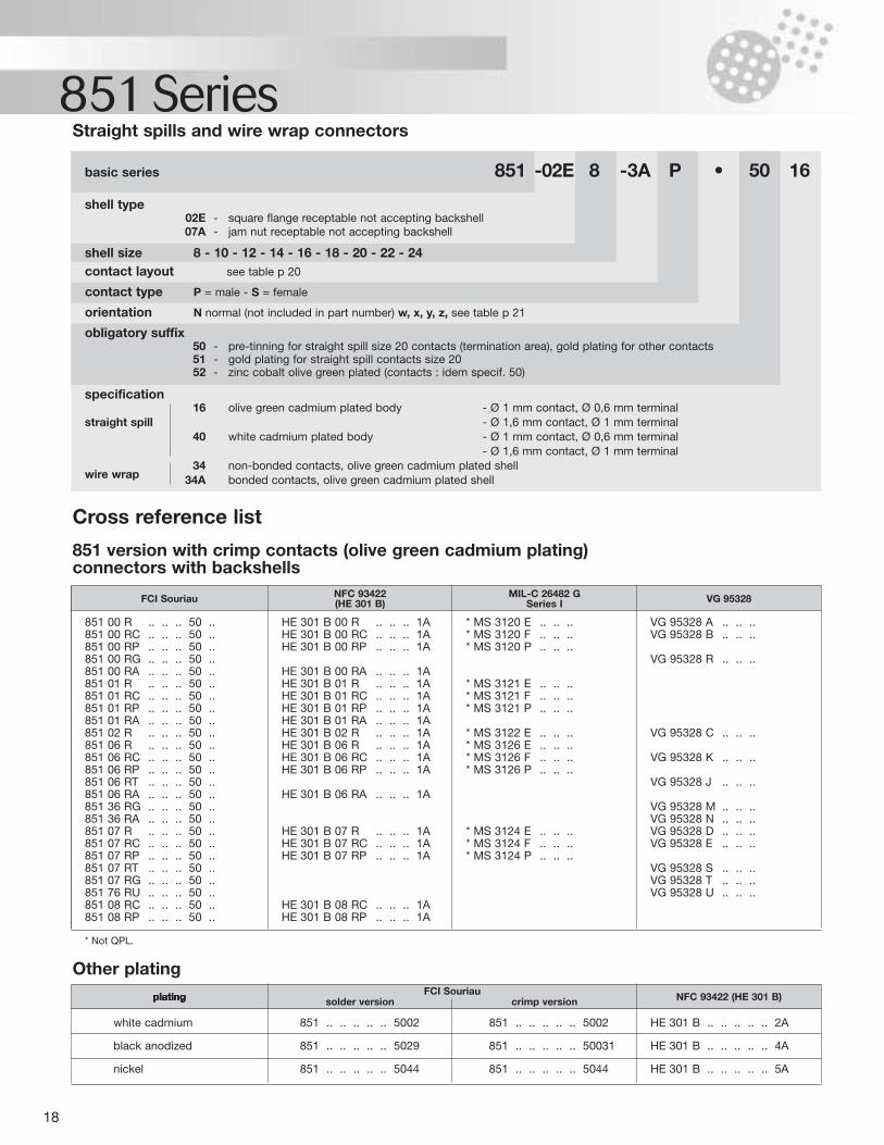
18
851 Series
851 00 R .. .. .. 50 .. HE 301 B 00 R .. .. .. 1A * MS 3120 E .. .. .. VG 95328 A .. .. ..851 00 RC .. .. .. 50 .. HE 301 B 00 RC .. .. .. 1A * MS 3120 F .. .. .. VG 95328 B .. .. ..851 00 RP .. .. .. 50 .. HE 301 B 00 RP .. .. .. 1A * MS 3120 P .. .. ..851 00 RG .. .. .. 50 .. VG 95328 R .. .. ..851 00 RA .. .. .. 50 .. HE 301 B 00 RA .. .. .. 1A851 01 R .. .. .. 50 .. HE 301 B 01 R .. .. .. 1A * MS 3121 E .. .. ..851 01 RC .. .. .. 50 .. HE 301 B 01 RC .. .. .. 1A * MS 3121 F .. .. ..851 01 RP .. .. .. 50 .. HE 301 B 01 RP .. .. .. 1A * MS 3121 P .. .. ..851 01 RA .. .. .. 50 .. HE 301 B 01 RA .. .. .. 1A851 02 R .. .. .. 50 .. HE 301 B 02 R .. .. .. 1A * MS 3122 E .. .. .. VG 95328 C .. .. ..851 06 R .. .. .. 50 .. HE 301 B 06 R .. .. .. 1A * MS 3126 E .. .. ..851 06 RC .. .. .. 50 .. HE 301 B 06 RC .. .. .. 1A * MS 3126 F .. .. .. VG 95328 K .. .. ..851 06 RP .. .. .. 50 .. HE 301 B 06 RP .. .. .. 1A * MS 3126 P .. .. ..851 06 RT .. .. .. 50 .. VG 95328 J .. .. ..851 06 RA .. .. .. 50 .. HE 301 B 06 RA .. .. .. 1A851 36 RG .. .. .. 50 .. VG 95328 M .. .. ..851 36 RA .. .. .. 50 .. VG 95328 N .. .. ..851 07 R .. .. .. 50 .. HE 301 B 07 R .. .. .. 1A * MS 3124 E .. .. .. VG 95328 D .. .. ..851 07 RC .. .. .. 50 .. HE 301 B 07 RC .. .. .. 1A * MS 3124 F .. .. .. VG 95328 E .. .. ..851 07 RP .. .. .. 50 .. HE 301 B 07 RP .. .. .. 1A * MS 3124 P .. .. ..851 07 RT .. .. .. 50 .. VG 95328 S .. .. ..851 07 RG .. .. .. 50 .. VG 95328 T .. .. ..851 76 RU .. .. .. 50 .. VG 95328 U .. .. ..851 08 RC .. .. .. 50 .. HE 301 B 08 RC .. .. .. 1A851 08 RP .. .. .. 50 .. HE 301 B 08 RP .. .. .. 1A
* Not QPL.
Other plating
white cadmium 851 .. .. .. .. .. 5002 851 .. .. .. .. .. 5002 HE 301 B .. .. .. .. .. 2A
black anodized 851 .. .. .. .. .. 5029 851 .. .. .. .. .. 50031 HE 301 B .. .. .. .. .. 4A
nickel 851 .. .. .. .. .. 5044 851 .. .. .. .. .. 5044 HE 301 B .. .. .. .. .. 5A
specification 16 olive green cadmium plated body - Ø 1 mm contact, Ø 0,6 mm terminal
straight spill - Ø 1,6 mm contact, Ø 1 mm terminal40 white cadmium plated body - Ø 1 mm contact, Ø 0,6 mm terminal
- Ø 1,6 mm contact, Ø 1 mm terminal34 non-bonded contacts, olive green cadmium plated shell
wire wrap 34A bonded contacts, olive green cadmium plated shell
obligatory suffix 50 - pre-tinning for straight spill size 20 contacts (termination area), gold plating for other contacts51 - gold plating for straight spill contacts size 2052 - zinc cobalt olive green plated (contacts : idem specif. 50)
orientation N normal (not included in part number) w, x, y, z, see table p 21
contact type P = male - S = female
contact layout see table p 20
shell size 8 - 10 - 12 - 14 - 16 - 18 - 20 - 22 - 24
shell type 02E - square flange receptable not accepting backshell07A - jam nut receptable not accepting backshell
basic series 851 -02E 8 -3A P • 50 16
Straight spills and wire wrap connectors
Cross reference list
851 version with crimp contacts (olive green cadmium plating)connectors with backshells
FCI Souriau NFC 93422(HE 301 B)
MIL-C 26482 GSeries I VG 95328
platingplatingplating solder version crimp version NFC 93422 (HE 301 B)FCI Souriau
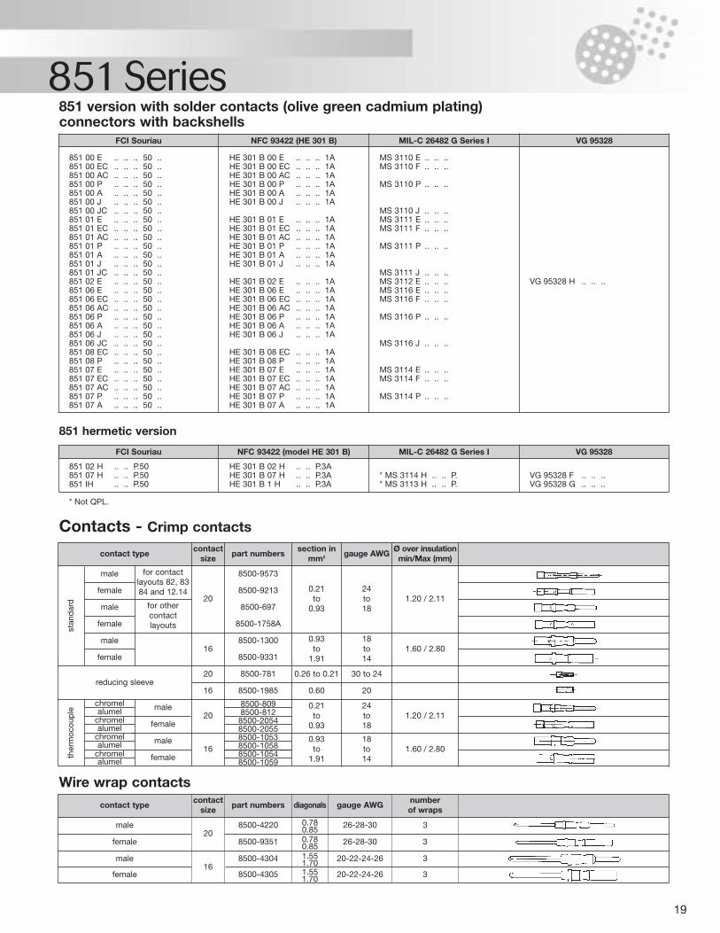
19
851 SeriesFCI Souriau NFC 93422 (HE 301 B) MIL-C 26482 G Series I VG 95328
FCI Souriau
8500-8098500-812
chromel male20
16
female
male
female
851 00 E .. .. .. 50 .. HE 301 B 00 E .. .. .. 1A MS 3110 E .. .. .. 851 00 EC .. .. .. 50 .. HE 301 B 00 EC .. .. .. 1A MS 3110 F .. .. .. 851 00 AC .. .. .. 50 .. HE 301 B 00 AC .. .. .. 1A851 00 P .. .. .. 50 .. HE 301 B 00 P .. .. .. 1A MS 3110 P .. .. .. 851 00 A .. .. .. 50 .. HE 301 B 00 A .. .. .. 1A851 00 J .. .. .. 50 .. HE 301 B 00 J .. .. .. 1A851 00 JC .. .. .. 50 .. MS 3110 J .. .. .. 851 01 E .. .. .. 50 .. HE 301 B 01 E .. .. .. 1A MS 3111 E .. .. .. 851 01 EC .. .. .. 50 .. HE 301 B 01 EC .. .. .. 1A MS 3111 F .. .. .. 851 01 AC .. .. .. 50 .. HE 301 B 01 AC .. .. .. 1A851 01 P .. .. .. 50 .. HE 301 B 01 P .. .. .. 1A MS 3111 P .. .. .. 851 01 A .. .. .. 50 .. HE 301 B 01 A .. .. .. 1A851 01 J .. .. .. 50 .. HE 301 B 01 J .. .. .. 1A851 01 JC .. .. .. 50 .. MS 3111 J .. .. .. 851 02 E .. .. .. 50 .. HE 301 B 02 E .. .. .. 1A MS 3112 E .. .. .. VG 95328 H .. .. .. 851 06 E .. .. .. 50 .. HE 301 B 06 E .. .. .. 1A MS 3116 E .. .. .. 851 06 EC .. .. .. 50 .. HE 301 B 06 EC .. .. .. 1A MS 3116 F .. .. .. 851 06 AC .. .. .. 50 .. HE 301 B 06 AC .. .. .. 1A851 06 P .. .. .. 50 .. HE 301 B 06 P .. .. .. 1A MS 3116 P .. .. .. 851 06 A .. .. .. 50 .. HE 301 B 06 A .. .. .. 1A851 06 J .. .. .. 50 .. HE 301 B 06 J .. .. .. 1A851 06 JC .. .. .. 50 .. MS 3116 J .. .. .. 851 08 EC .. .. .. 50 .. HE 301 B 08 EC .. .. .. 1A851 08 P .. .. .. 50 .. HE 301 B 08 P .. .. .. 1A851 07 E .. .. .. 50 .. HE 301 B 07 E .. .. .. 1A MS 3114 E .. .. .. 851 07 EC .. .. .. 50 .. HE 301 B 07 EC .. .. .. 1A MS 3114 F .. .. .. 851 07 AC .. .. .. 50 .. HE 301 B 07 AC .. .. .. 1A851 07 P .. .. .. 50 .. HE 301 B 07 P .. .. .. 1A MS 3114 P .. .. .. 851 07 A .. .. .. 50 .. HE 301 B 07 A .. .. .. 1A
851 hermetic version
851 02 H .. .. P.50 HE 301 B 02 H .. .. P.3A851 07 H .. .. P.50 HE 301 B 07 H .. .. P.3A * MS 3114 H .. .. P. VG 95328 F .. .. .. 851 IH .. .. P.50 HE 301 B 1 H .. .. P.3A * MS 3113 H .. .. P. VG 95328 G .. .. ..
* Not QPL.
851 version with solder contacts (olive green cadmium plating)connectors with backshells
NFC 93422 (model HE 301 B) MIL-C 26482 G Series I VG 95328
contact type
male for contactlayouts 82, 8384 and 12.14
20
16
8500-9573
0.21to
0.93
0.93to
1.91
24to18
18to14
1.20 / 2.11
1.60 / 2.80
8500-9213
8500-697
8500-1758A
8500-1300
8500-9331
for othercontactlayouts
female
male
female
male
female
reducing sleeve20 8500-781 0.26 to 0.21 30 to 24
16 8500-1985 0.60
0.21to
0.93
0.93to
1.91
24to18
18to14
1.20 / 2.11
1.60 / 2.80
20
contactsize
part numberssection in
mm2 gauge AWGØ over insulation
min/Max (mm)
alumelchromelalumel
chromelalumel
chromelalumel
8500-20548500-20558500-10538500-10588500-10548500-1059
Contacts - Crimp contacts
stan
dar
d
contact type
male20
16
8500-4220 26-28-30
26-28-30
20-22-24-26
20-22-24-26
0.780.850.780.851.551.701.551.70
3
3
3
3
8500-9351
8500-4304
8500-4305
female
male
female
contactsize
part numbers gauge AWGdiagonalsnumber of wraps
Wire wrap contacts
ther
moc
oup
le
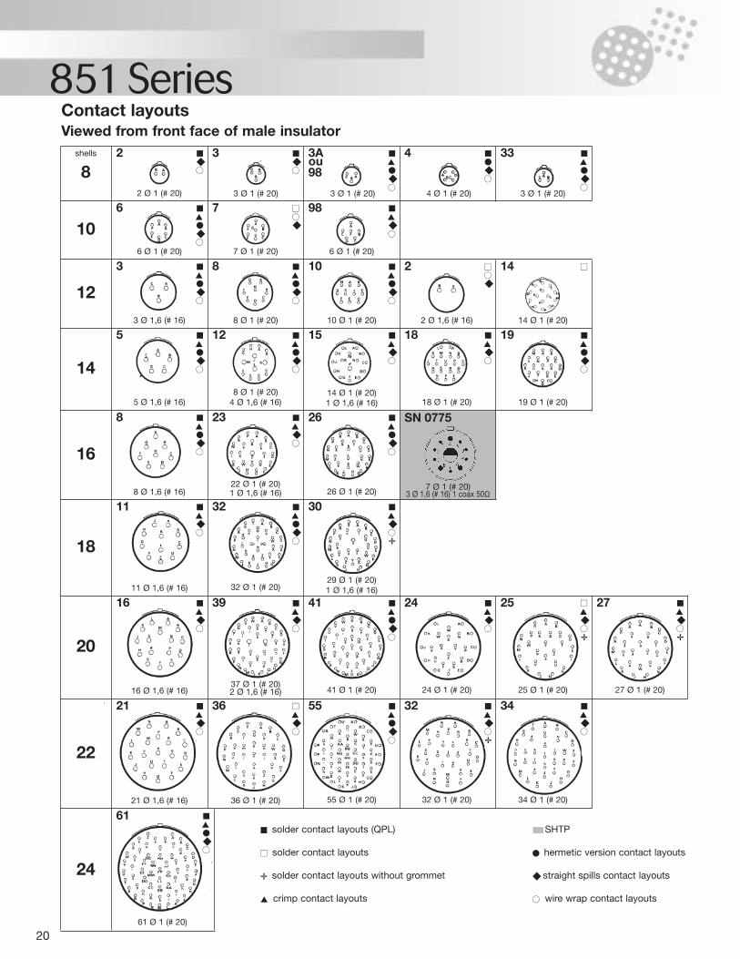
20
851 SeriesContact layoutsViewed from front face of male insulator
shells
82
3
3A ou
98
4
33
106
7
98
12
3
8
10
2
14
14
5
12
15
18
19
16
8
23
26
SN 0775
18
11
32
30
20
16
39
41
24
25
27
22
21
36
55
32
34
24
61
solder contact layouts (QPL) SHTP
solder contact layouts hermetic version contact layouts
solder contact layouts without grommet straight spills contact layouts
crimp contact layouts wire wrap contact layouts
2 Ø 1 (# 20)
6 Ø 1 (# 20)
3 Ø 1,6 (# 16)
7 Ø 1 (# 20)
8 Ø 1 (# 20)
6 Ø 1 (# 20)
10 Ø 1 (# 20) 2 Ø 1,6 (# 16) 14 Ø 1 (# 20)
5 Ø 1,6 (# 16)8 Ø 1 (# 20)
4 Ø 1,6 (# 16)14 Ø 1 (# 20)1 Ø 1,6 (# 16)
8 Ø 1,6 (# 16)22 Ø 1 (# 20)1 Ø 1,6 (# 16) 26 Ø 1 (# 20) 7 Ø 1 (# 20)
3 Ø 1,6 (# 16) 1 coax 50Ω
11 Ø 1,6 (# 16) 32 Ø 1 (# 20)29 Ø 1 (# 20)1 Ø 1,6 (# 16)
16 Ø 1,6 (# 16)37 Ø 1 (# 20)2 Ø 1,6 (# 16) 24 Ø 1 (# 20) 25 Ø 1 (# 20) 27 Ø 1 (# 20)41 Ø 1 (# 20)
21 Ø 1,6 (# 16)
61 Ø 1 (# 20)
36 Ø 1 (# 20) 32 Ø 1 (# 20) 34 Ø 1 (# 20)55 Ø 1 (# 20)
18 Ø 1 (# 20) 19 Ø 1 (# 20)
3 Ø 1 (# 20) 3 Ø 1 (# 20) 4 Ø 1 (# 20) 3 Ø 1 (# 20)
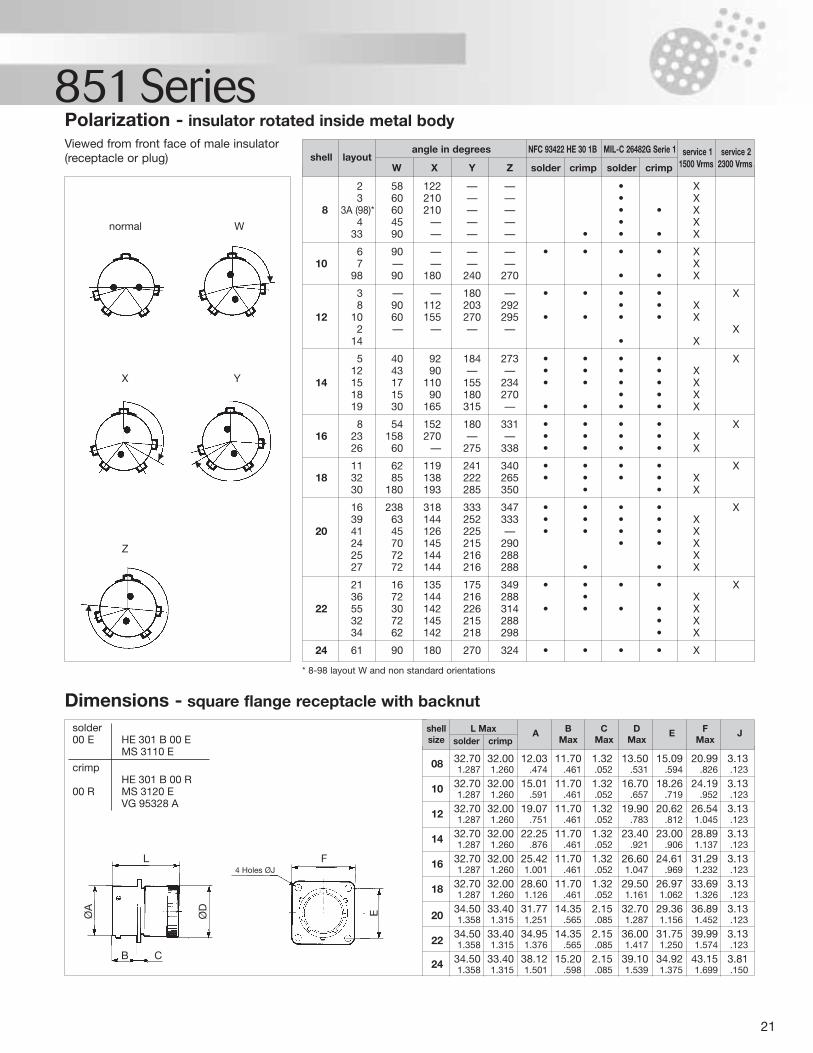
21
851 Series
2 58 122 — — • X3 60 210 — — • X
8 3A (98)* 60 210 — — • • X4 45 — — — • X
33 90 — — — • • • X
6 90 — — — • • • • X10 7 — — — — X
98 90 180 240 270 • • X
3 — — 180 — • • • • X8 90 112 203 292 • • X
12 10 60 155 270 295 • • • • X2 — — — — X
14 • X
5 40 92 184 273 • • • • X12 43 90 — — • • • • X
14 15 17 110 155 234 • • • • X18 15 90 180 270 • • X19 30 165 315 — • • • • X
8 54 152 180 331 • • • • X16 23 158 270 — — • • • • X
26 60 — 275 338 • • • • X
11 62 119 241 340 • • • • X18 32 85 138 222 265 • • • • X
30 180 193 285 350 • • X
16 238 318 333 347 • • • • X39 63 144 252 333 • • • • X
20 41 45 126 225 — • • • • X24 70 145 215 290 • • X25 72 144 216 288 X27 72 144 216 288 • • X
21 16 135 175 349 • • • • X36 72 144 216 288 • X
22 55 30 142 226 314 • • • • X32 72 145 215 288 • X34 62 142 218 298 • X
24 61 90 180 270 324 • • • • X
Polarization - insulator rotated inside metal bodyViewed from front face of male insulator(receptacle or plug)
Dimensions - square flange receptacle with backnut
solder00 E HE 301 B 00 E
MS 3110 E
crimpHE 301 B 00 R
00 R MS 3120 EVG 95328 A
shell layoutangle in degrees NFC 93422 HE 30 1B MIL-C 26482G Serie 1 service 1 service 2
W X Y Z solder crimp solder crimp 1500 Vrms 2300 Vrms
* 8-98 layout W and non standard orientations
08 32.70 32.00 12.03 11.70 1.32 13.50 15.09 20.99 3.131.287 1.260 .474 .461 .052 .531 .594 .826 .123
10 32.70 32.00 15.01 11.70 1.32 16.70 18.26 24.19 3.131.287 1.260 .591 .461 .052 .657 .719 .952 .123
12 32.70 32.00 19.07 11.70 1.32 19.90 20.62 26.54 3.131.287 1.260 .751 .461 .052 .783 .812 1.045 .123
14 32.70 32.00 22.25 11.70 1.32 23.40 23.00 28.89 3.131.287 1.260 .876 .461 .052 .921 .906 1.137 .123
16 32.70 32.00 25.42 11.70 1.32 26.60 24.61 31.29 3.131.287 1.260 1.001 .461 .052 1.047 .969 1.232 .123
18 32.70 32.00 28.60 11.70 1.32 29.50 26.97 33.69 3.131.287 1.260 1.126 .461 .052 1.161 1.062 1.326 .123
2034.50 33.40 31.77 14.35 2.15 32.70 29.36 36.89 3.131.358 1.315 1.251 .565 .085 1.287 1.156 1.452 .123
2234.50 33.40 34.95 14.35 2.15 36.00 31.75 39.99 3.131.358 1.315 1.376 .565 .085 1.417 1.250 1.574 .123
24 34.50 33.40 38.12 15.20 2.15 39.10 34.92 43.15 3.811.358 1.315 1.501 .598 .085 1.539 1.375 1.699 .150
shell L Max A B C D E F Jsize solder crimp Max Max Max Max
4 Holes ØJ
normal W
X
Z
L
ØD EØA
B C
F
Y
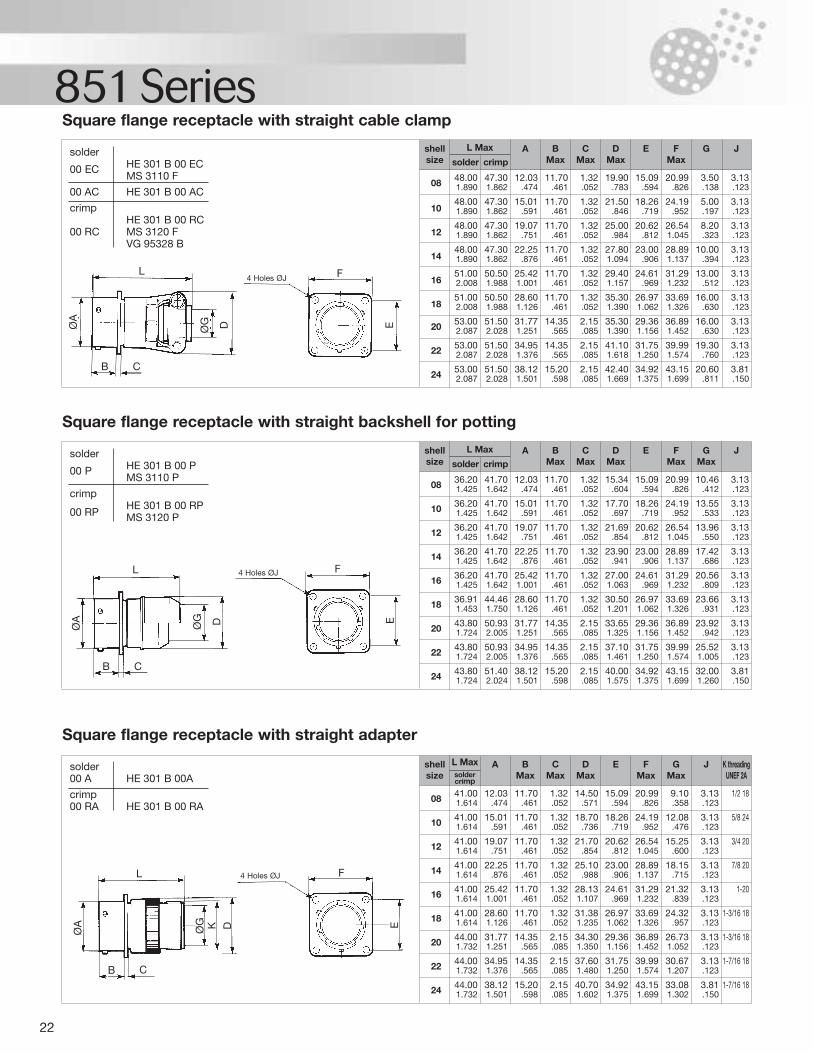
22
851 SeriesSquare flange receptacle with straight cable clamp
Square flange receptacle with straight backshell for potting
Square flange receptacle with straight adapter
solder
00 P HE 301 B 00 PMS 3110 P
crimpHE 301 B 00 RP
00 RP MS 3120 P
solder00 A HE 301 B 00A
crimp00 RA HE 301 B 00 RA
solder
00 EC HE 301 B 00 ECMS 3110 F
00 AC HE 301 B 00 AC
crimpHE 301 B 00 RC
00 RC MS 3120 FVG 95328 B
08 41.00 12.03 11.70 1.32 14.50 15.09 20.99 9.10 3.13 1/2 181.614 .474 .461 .052 .571 .594 .826 .358 .123
10 41.00 15.01 11.70 1.32 18.70 18.26 24.19 12.08 3.13 5/8 241.614 .591 .461 .052 .736 .719 .952 .476 .123
12 41.00 19.07 11.70 1.32 21.70 20.62 26.54 15.25 3.13 3/4 201.614 .751 .461 .052 .854 .812 1.045 .600 .123
14 41.00 22.25 11.70 1.32 25.10 23.00 28.89 18.15 3.13 7/8 201.614 .876 .461 .052 .988 .906 1.137 .715 .123
16 41.00 25.42 11.70 1.32 28.13 24.61 31.29 21.32 3.13 1-201.614 1.001 .461 .052 1.107 .969 1.232 .839 .123
18 41.00 28.60 11.70 1.32 31.38 26.97 33.69 24.32 3.13 1-3/16 181.614 1.126 .461 .052 1.235 1.062 1.326 .957 .123
20 44.00 31.77 14.35 2.15 34.30 29.36 36.89 26.73 3.13 1-3/16 181.732 1.251 .565 .085 1.350 1.156 1.452 1.052 .123
22 44.00 34.95 14.35 2.15 37.60 31.75 39.99 30.67 3.13 1-7/16 181.732 1.376 .565 .085 1.480 1.250 1.574 1.207 .123
24 44.00 38.12 15.20 2.15 40.70 34.92 43.15 33.08 3.81 1-7/16 181.732 1.501 .598 .085 1.602 1.375 1.699 1.302 .150
shellsize
BMax
A C Max
DMax
E F Max
GMax
J K threadingUNEF 2A
L Maxsoldercrimp
08 48.00 47.30 12.03 11.70 1.32 19.90 15.09 20.99 3.50 3.131.890 1.862 .474 .461 .052 .783 .594 .826 .138 .123
1048.00 47.30 15.01 11.70 1.32 21.50 18.26 24.19 5.00 3.131.890 1.862 .591 .461 .052 .846 .719 .952 .197 .123
1248.00 47.30 19.07 11.70 1.32 25.00 20.62 26.54 8.20 3.131.890 1.862 .751 .461 .052 .984 .812 1.045 .323 .123
1448.00 47.30 22.25 11.70 1.32 27.80 23.00 28.89 10.00 3.131.890 1.862 .876 .461 .052 1.094 .906 1.137 .394 .123
1651.00 50.50 25.42 11.70 1.32 29.40 24.61 31.29 13.00 3.132.008 1.988 1.001 .461 .052 1.157 .969 1.232 .512 .123
1851.00 50.50 28.60 11.70 1.32 35.30 26.97 33.69 16.00 3.132.008 1.988 1.126 .461 .052 1.390 1.062 1.326 .630 .123
20 53.00 51.50 31.77 14.35 2.15 35.30 29.36 36.89 16.00 3.132.087 2.028 1.251 .565 .085 1.390 1.156 1.452 .630 .123
22 53.00 51.50 34.95 14.35 2.15 41.10 31.75 39.99 19.30 3.132.087 2.028 1.376 .565 .085 1.618 1.250 1.574 .760 .123
24 53.00 51.50 38.12 15.20 2.15 42.40 34.92 43.15 20.60 3.812.087 2.028 1.501 .598 .085 1.669 1.375 1.699 .811 .150
shellsize
A B Max
C Max
D Max
E FMax
G JL Max
solder crimp
08 36.20 41.70 12.03 11.70 1.32 15.34 15.09 20.99 10.46 3.131.425 1.642 .474 .461 .052 .604 .594 .826 .412 .123
10 36.20 41.70 15.01 11.70 1.32 17.70 18.26 24.19 13.55 3.131.425 1.642 .591 .461 .052 .697 .719 .952 .533 .123
12 36.20 41.70 19.07 11.70 1.32 21.69 20.62 26.54 13.96 3.131.425 1.642 .751 .461 .052 .854 .812 1.045 .550 .123
14 36.20 41.70 22.25 11.70 1.32 23.90 23.00 28.89 17.42 3.131.425 1.642 .876 .461 .052 .941 .906 1.137 .686 .123
16 36.20 41.70 25.42 11.70 1.32 27.00 24.61 31.29 20.56 3.131.425 1.642 1.001 .461 .052 1.063 .969 1.232 .809 .123
18 36.91 44.46 28.60 11.70 1.32 30.50 26.97 33.69 23.66 3.131.453 1.750 1.126 .461 .052 1.201 1.062 1.326 .931 .123
20 43.80 50.93 31.77 14.35 2.15 33.65 29.36 36.89 23.92 3.131.724 2.005 1.251 .565 .085 1.325 1.156 1.452 .942 .123
22 43.80 50.93 34.95 14.35 2.15 37.10 31.75 39.99 25.52 3.131.724 2.005 1.376 .565 .085 1.461 1.250 1.574 1.005 .123
24 43.80 51.40 38.12 15.20 2.15 40.00 34.92 43.15 32.00 3.811.724 2.024 1.501 .598 .085 1.575 1.375 1.699 1.260 .150
shellsize
A B Max
C Max
D Max
E FMax
GMax
JL Max
solder crimp
4 Holes ØJ
4 Holes ØJ
4 Holes ØJ
L
CB
CB
CB
F
L F
L F
EE
DØG
DØG
ØA
ØA
E
ØA
ØG K D
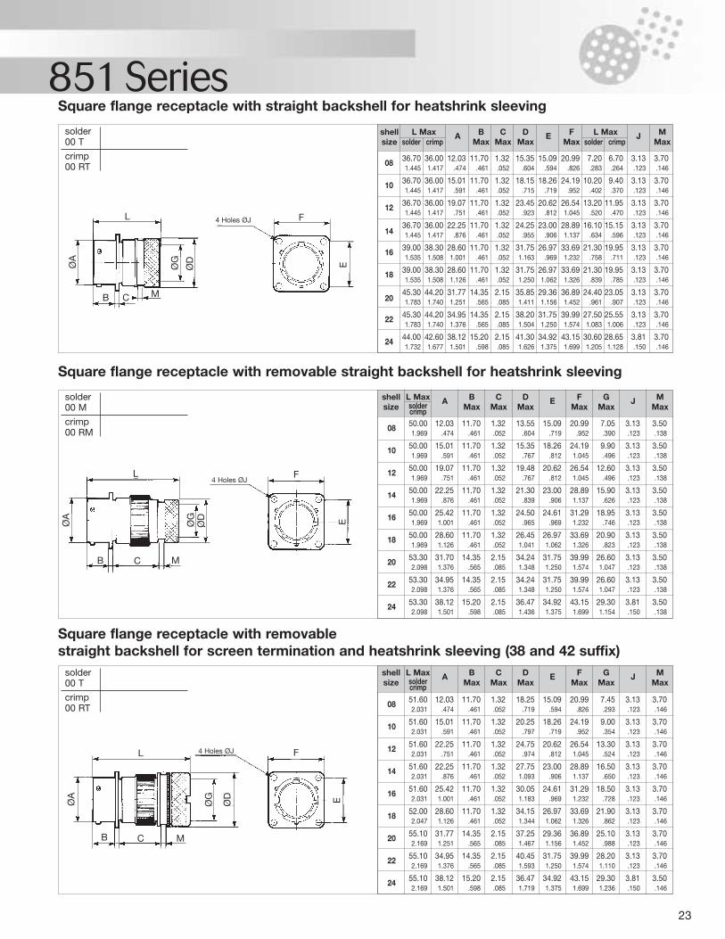
23
851 Series
08 51.60 12.03 11.70 1.32 18.25 15.09 20.99 7.45 3.13 3.702.031 .474 .461 .052 .719 .594 .826 .293 .123 .146
10 51.60 15.01 11.70 1.32 20.25 18.26 24.19 9.00 3.13 3.702.031 .591 .461 .052 .797 .719 .952 .354 .123 .146
12 51.60 22.25 11.70 1.32 24.75 20.62 26.54 13.30 3.13 3.702.031 .751 .461 .052 .974 .812 1.045 .524 .123 .146
14 51.60 22.25 11.70 1.32 27.75 23.00 28.89 16.50 3.13 3.702.031 .876 .461 .052 1.093 .906 1.137 .650 .123 .146
16 51.60 25.42 11.70 1.32 30.05 24.61 31.29 18.50 3.13 3.702.031 1.001 .461 .052 1.183 .969 1.232 .728 .123 .146
18 52.00 28.60 11.70 1.32 34.15 26.97 33.69 21.90 3.13 3.702.047 1.126 .461 .052 1.344 1.062 1.326 .862 .123 .146
20 55.10 31.77 14.35 2.15 37.25 29.36 36.89 25.10 3.13 3.702.169 1.251 .565 .085 1.467 1.156 1.452 .988 .123 .146
22 55.10 34.95 14.35 2.15 40.45 31.75 39.99 28.20 3.13 3.702.169 1.376 .565 .085 1.593 1.250 1.574 1.110 .123 .146
24 55.10 38.12 15.20 2.15 36.47 34.92 43.15 29.30 3.81 3.502.169 1.501 .598 .085 1.719 1.375 1.699 1.236 .150 .146
08 36.70 36.00 12.03 11.70 1.32 15.35 15.09 20.99 7.20 6.70 3.13 3.701.445 1.417 .474 .461 .052 .604 .594 .826 .283 .264 .123 .146
10 36.70 36.00 15.01 11.70 1.32 18.15 18.26 24.19 10.20 9.40 3.13 3.701.445 1.417 .591 .461 .052 .715 .719 .952 .402 .370 .123 .146
12 36.70 36.00 19.07 11.70 1.32 23.45 20.62 26.54 13.20 11.95 3.13 3.701.445 1.417 .751 .461 .052 .923 .812 1.045 .520 .470 .123 .146
1436.70 36.00 22.25 11.70 1.32 24.25 23.00 28.89 16.10 15.15 3.13 3.701.445 1.417 .876 .461 .052 .955 .906 1.137 .634 .596 .123 .146
16 39.00 38.30 28.60 11.70 1.32 31.75 26.97 33.69 21.30 19.95 3.13 3.701.535 1.508 1.001 .461 .052 1.163 .969 1.232 .758 .711 .123 .146
18 39.00 38.30 28.60 11.70 1.32 31.75 26.97 33.69 21.30 19.95 3.13 3.701.535 1.508 1.126 .461 .052 1.250 1.062 1.326 .839 .785 .123 .146
2045.30 44.20 31.77 14.35 2.15 35.85 29.36 36.89 24.40 23.05 3.13 3.701.783 1.740 1.251 .565 .085 1.411 1.156 1.452 .961 .907 .123 .146
22 45.30 44.20 34.95 14.35 2.15 38.20 31.75 39.99 27.50 25.55 3.13 3.701.783 1.740 1.376 .565 .085 1.504 1.250 1.574 1.083 1.006 .123 .146
24 44.00 42.60 38.12 15.20 2.15 41.30 34.92 43.15 30.60 28.65 3.81 3.701.732 1.677 1.501 .598 .085 1.626 1.375 1.699 1.205 1.128 .150 .146
solder00 T
crimp00 RT
Square flange receptacle with straight backshell for heatshrink sleeving
shell L Max A B C D E F L Max J Msize solder crimp Max Max Max Max solder crimp Max
solder00 M
crimp00 RM
Square flange receptacle with removable straight backshell for heatshrink sleeving
08 50.00 12.03 11.70 1.32 13.55 15.09 20.99 7.05 3.13 3.501.969 .474 .461 .052 .604 .719 .952 .390 .123 .138
10 50.00 15.01 11.70 1.32 15.35 18.26 24.19 9.90 3.13 3.501.969 .591 .461 .052 .767 .812 1.045 .496 .123 .138
12 50.00 19.07 11.70 1.32 19.48 20.62 26.54 12.60 3.13 3.501.969 .751 .461 .052 .767 .812 1.045 .496 .123 .138
14 50.00 22.25 11.70 1.32 21.30 23.00 28.89 15.90 3.13 3.501.969 .876 .461 .052 .839 .906 1.137 .626 .123 .138
16 50.00 25.42 11.70 1.32 24.50 24.61 31.29 18.95 3.13 3.501.969 1.001 .461 .052 .965 .969 1.232 .746 .123 .138
18 50.00 28.60 11.70 1.32 26.45 26.97 33.69 20.90 3.13 3.501.969 1.126 .461 .052 1.041 1.062 1.326 .823 .123 .138
20 53.30 31.70 14.35 2.15 34.24 31.75 39.99 26.60 3.13 3.502.098 1.376 .565 .085 1.348 1.250 1.574 1.047 .123 .138
22 53.30 34.95 14.35 2.15 34.24 31.75 39.99 26.60 3.13 3.502.098 1.376 .565 .085 1.348 1.250 1.574 1.047 .123 .138
24 53.30 38.12 15.20 2.15 36.47 34.92 43.15 29.30 3.81 3.502.098 1.501 .598 .085 1.436 1.375 1.699 1.154 .150 .138
shell L Max A B C D E F G J Msize solder Max Max Max Max Max Maxcrimp
solder00 T
crimp00 RT
Square flange receptacle with removable straight backshell for screen termination and heatshrink sleeving (38 and 42 suffix)
4 Holes ØJ
4 Holes ØJ
4 Holes ØJ
L
C MB
F
EØD
ØG
ØA
L
C MB
F
EØD
ØG
ØA
L
C MB
F
EØD
ØG
ØA
shell L Max A B C D E F G J Msize solder Max Max Max Max Max Maxcrimp
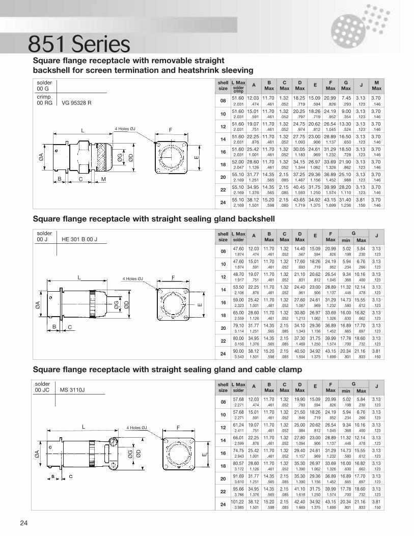
24
851 Series
solder00 JC MS 3110J
Square flange receptacle with straight sealing gland and cable clamp
solder00 J HE 301 B 00 J
Square flange receptacle with straight sealing gland backshell
08 47.60 12.03 11.70 1.32 14.40 15.09 20.99 5.02 5.84 3.131.874 .474 .461 .052 .567 .594 .826 .198 .230 .123
10 47.60 15.01 11.70 1.32 17.60 18.26 24.19 5.94 6.76 3.131.874 .591 .461 .052 .693 .719 .952 .234 .266 .123
12 48.70 19.07 11.70 1.32 21.10 20.62 26.54 9.34 10.16 3.131.917 .751 .461 .052 .831 .812 1.045 .368 .400 .123
14 53.50 22.25 11.70 1.32 24.40 23.00 28.89 11.32 12.14 3.132.106 .876 .461 .052 .961 .906 1.137 .446 .478 .123
16 59.00 25.42 11.70 1.32 27.60 24.61 31.29 14.73 15.55 3.132.323 1.001 .461 .052 1.087 .969 1.232 .580 .612 .123
18 65.00 28.60 11.70 1.32 30.80 26.97 33.69 16.00 16.82 3.132.559 1.126 .461 .052 1.213 1.062 1.326 .630 .662 .123
20 79.10 31.77 14.35 2.15 34.10 29.36 36.89 16.89 17.70 3.133.114 1.251 .565 .085 1.343 1.156 1.452 .665 .697 .123
22 80.00 34.95 14.35 2.15 37.30 31.75 39.99 17.78 18.60 3.133.150 1.376 .565 .085 1.469 1.250 1.574 .700 .732 .123
24 90.00 38.12 15.20 2.15 40.50 34.92 43.15 20.34 21.16 3.813.543 1.501 .598 .085 1.594 1.375 1.699 .801 .833 .150
shell L Max A B C D E F G Jsize solder Max Max Max Max min Max
08 57.68 12.03 11.70 1.32 19.90 15.09 20.99 5.02 5.84 3.132.271 .474 .461 .052 .783 .594 .826 .198 .230 .123
10 57.68 15.01 11.70 1.32 21.50 18.26 24.19 5.94 6.76 3.132.271 .591 .461 .052 .846 .719 .952 .234 .266 .123
12 61.24 19.07 11.70 1.32 25.00 20.62 26.54 9.34 10.16 3.132.411 .751 .461 .052 .984 .812 1.045 .368 .400 .123
14 66.01 22.25 11.70 1.32 27.80 23.00 28.89 11.32 12.14 3.132.599 .876 .461 .052 1.094 .906 1.137 .446 .478 .123
16 74.75 25.42 11.70 1.32 29.40 24.61 31.29 14.73 15.55 3.132.943 1.001 .461 .052 1.157 .969 1.232 .580 .612 .123
18 80.57 28.60 11.70 1.32 35.30 26.97 33.69 16.00 16.82 3.133.172 1.126 .461 .052 1.390 1.062 1.326 .630 .662 .123
20 91.69 31.77 14.35 2.15 35.30 29.36 36.89 16.89 17.70 3.133.610 1.251 .565 .085 1.390 1.156 1.452 .665 .697 .123
22 95.66 34.95 14.35 2.15 41.10 31.75 39.99 17.78 18.60 3.133.766 1.376 .565 .085 1.618 1.250 1.574 .700 .732 .123
24 101.22 38.12 15.20 2.15 42.40 34.92 43.15 20.34 21.16 3.813.985 1.501 .598 .085 1.669 1.375 1.699 .801 .833 .150
shell L Max A B C D E F G Jsize solder Max Max Max Max min Max
solder00 G
crimp00 RG VG 95328 R
Square flange receptacle with removable straight backshell for screen termination and heatshrink sleeving
08 51.60 12.03 11.70 1.32 18.25 15.09 20.99 7.45 3.13 3.702.031 .474 .461 .052 .719 .594 .826 .293 .123 .146
10 51.60 15.01 11.70 1.32 20.25 18.26 24.19 9.00 3.13 3.702.031 .591 .461 .052 .797 .719 .952 .354 .123 .146
12 51.60 19.07 11.70 1.32 24.75 20.62 26.54 13.30 3.13 3.702.031 .751 .461 .052 .974 .812 1.045 .524 .123 .146
14 51.60 22.25 11.70 1.32 27.75 23.00 28.89 16.50 3.13 3.702.031 .876 .461 .052 1.093 .906 1.137 .650 .123 .146
16 51.60 25.42 11.70 1.32 30.05 24.61 31.29 18.50 3.13 3.702.031 1.001 .461 .052 1.183 .969 1.232 .728 .123 .146
18 52.00 28.60 11.70 1.32 34.15 26.97 33.69 21.90 3.13 3.702.047 1.126 .461 .052 1.344 1.062 1.326 .862 .123 .146
20 55.10 31.77 14.35 2.15 37.25 29.36 36.89 25.10 3.13 3.702.169 1.251 .565 .085 1.467 1.156 1.452 .988 .123 .146
22 55.10 34.95 14.35 2.15 40.45 31.75 39.99 28.20 3.13 3.702.169 1.376 .565 .085 1.593 1.250 1.574 1.110 .123 .146
24 55.10 38.12 15.20 2.15 43.65 34.92 43.15 31.40 3.81 3.702.169 1.501 .598 .085 1.719 1.375 1.699 1.236 .150 .146
shell L Max A B C D E F G J Msize solder Max Max Max Max Max Maxcrimp
4 Holes ØJ
4 Holes ØJ
4 Holes ØJ
L
C MB
F
EØD
ØG
ØA
L
CB
F
EØD
ØG
ØA
L F
EØD
ØG
ØA
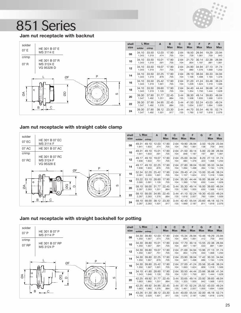
25
851 SeriesJam nut receptacle with backnut
Jam nut receptacle with straight backshell for potting
Jam nut receptacle with straight cable clamp
08 34.10 33.50 12.03 17.90 2.64 18.50 26.94 19.29 23.941.343 1.319 .474 .705 .104 .728 1.061 .759 .943
10 34.10 33.50 15.01 17.90 2.64 21.70 30.14 22.38 26.941.343 1.319 .591 .705 .104 .854 1.187 .881 1.061
12 34.10 33.50 19.07 17.90 2.64 24.90 34.94 27.13 31.741.343 1.319 .751 .705 .104 .980 1.376 1.068 1.250
14 34.10 33.50 22.25 17.90 2.64 28.10 38.04 30.33 34.941.343 1.319 .876 .705 .104 1.106 1.498 1.194 1.376
16 34.10 33.50 25.42 17.90 2.64 31.20 41.24 33.48 38.241.343 1.319 1.001 .705 .104 1.228 1.624 1.318 1.506
18 34.10 33.50 28.60 17.90 2.64 34.40 44.44 36.68 41.341.343 1.319 1.126 .705 .104 1.354 1.750 1.444 1.628
20 39.30 37.90 31.77 22.45 3.44 38.30 49.14 39.83 46.041.547 1.492 1.251 .884 .135 1.508 1.935 1.568 1.813
22 39.30 37.90 34.95 22.45 3.44 41.50 52.24 43.03 49.241.547 1.492 1.376 .884 .135 1.634 2.057 1.694 1.939
24 39.30 37.90 38.12 23.30 3.44 44.70 55.54 46.18 52.741.547 1.492 1.501 .917 .135 1.760 2.187 1.818 2.076
shellsize
L Max
solder crimp
08 49.31 49.10 12.03 17.90 2.64 19.90 26.94 3.50 19.29 23.941.941 1.933 .474 .705 .104 .783 1.061 .138 .759 .943
10 49.31 49.10 15.01 17.90 2.64 21.50 30.14 5.00 22.38 26.941.941 1.933 .591 .705 .104 .846 1.187 .197 .881 1.061
12 49.17 49.10 19.07 17.90 2.64 25.00 34.94 8.20 27.13 31.741.936 1.933 .751 .705 .104 .984 1.376 .323 1.068 1.250
14 49.17 49.10 22.25 17.90 2.64 27.80 38.04 10.00 30.33 34.941.936 1.933 .876 .705 .104 1.094 1.498 .394 1.194 1.376
16 52.34 52.20 25.42 17.90 2.64 29.40 41.24 13.00 33.48 38.242.061 2.055 1.001 .705 .104 1.157 1.624 .512 1.318 1.506
18 53.22 53.10 28.60 17.90 2.64 35.30 44.44 16.00 36.68 41.342.095 2.091 1.126 .705 .104 1.390 1.750 .630 1.444 1.628
20 58.10 58.00 31.77 22.45 3.44 35.30 49.14 16.00 39.83 46.042.287 2.283 1.251 .884 .135 1.390 1.935 .630 1.568 1.813
22 58.10 58.00 34.95 22.45 3.44 41.10 52.24 19.30 43.03 49.242.287 2.283 1.376 .884 .135 1.618 2.057 .760 1.694 1.939
24 58.10 58.00 38.12 23.30 3.44 42.40 55.54 20.60 46.18 52.742.287 2.283 1.501 .917 .135 1.669 2.187 .811 1.818 2.076
shellsize
A B Max
C Max
D Max
F Max
G P Max
S Max
solder
07 E HE 301 B 07 EMS 3114 E
crimpHE 301 B 07 R
07 R MS 3124 EVG 95328 D
solder
07 P HE 301 B 07 PMS 3114 P
crimpHE 301 B 07 RP
07 RP MS 3124 P
solder
07 EC HE 301 B 07 ECMS 3114 F
07 AC HE 301 B 07 AC
crimpHE 301 B 07 RC
07 RC MS 3124 FVG 95328 E
08 34.30 39.80 12.03 17.90 2.64 15.34 26.94 10.46 19.29 23.941.350 1.567 .474 .705 .104 .604 1.061 .412 .759 .943
10 34.30 39.80 15.01 17.90 2.64 17.70 30.14 13.55 22.38 26.941.350 1.567 .591 .705 .104 .697 1.187 .533 .881 1.061
12 34.30 39.80 19.07 17.90 2.64 21.69 34.94 13.96 27.13 31.741.350 1.567 .751 .705 .104 .854 1.376 .550 1.068 1.250
14 34.30 39.80 22.25 17.90 2.64 23.90 38.04 17.42 30.33 34.941.350 1.567 .876 .705 .104 .941 1.498 .686 1.194 1.376
16 34.30 39.80 25.42 17.90 2.64 27.00 41.24 20.56 33.48 38.241.350 1.567 1.001 .705 .104 1.063 1.624 .809 1.318 1.506
18 34.10 41.80 28.60 17.90 2.64 30.50 44.44 23.66 36.68 41.341.343 1.646 1.126 .705 .104 1.201 1.750 .931 1.444 1.628
20 42.25 49.92 31.77 22.45 3.44 33.65 49.14 23.92 39.83 46.041.663 1.965 1.251 .884 .135 1.325 1.935 .942 1.568 1.813
22 42.25 49.92 34.95 22.45 3.44 37.10 52.24 25.52 43.03 49.241.663 1.965 1.376 .884 .135 1.461 2.057 1.005 1.694 1.939
24 43.26 51.30 38.12 23.30 3.44 40.00 55.54 32.00 46.18 52.741.703 2.020 1.501 .917 .135 1.575 2.187 1.260 1.818 2.076
shellsize
A B Max
C Max
D Max
F Max
GMax
P Max
S Max
L Max
solder crimp
L Max
solder crimp
A BMax
CMax
DMax
FMax
PMax
SMax
ØFL
CB
P
SØD
ØA
ØFL
CB
P
S
ØG DØA
ØFL
CB
P
SØG DØA
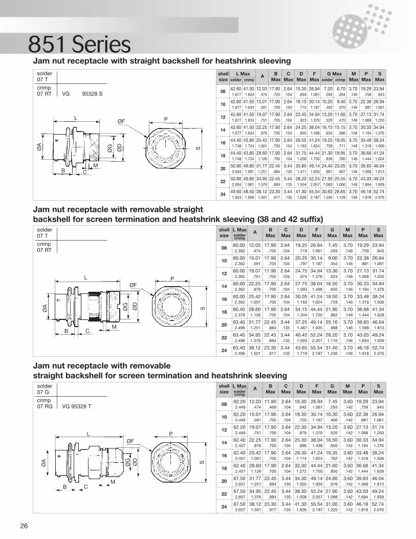
26
851 Seriessolder07 T
crimp07 RT VG 95328 S
Jam nut receptacle with straight backshell for heatshrink sleeving
08 42.60 41.50 12.03 17.90 2.64 15.35 26.94 7.20 6.70 3.70 19.29 23.941.677 1.634 .474 .705 .104 .604 1.061 .283 .264 .146 .759 .943
10 42.60 41.50 15.01 17.90 2.64 18.15 30.14 10.20 9.40 3.70 22.38 26.941.677 1.634 .591 .705 .104 .715 1.187 .402 .370 .146 .881 1.061
12 42.60 41.50 19.07 17.90 2.64 23.45 34.94 13.20 11.95 3.70 27.13 31.741.677 1.634 .751 .705 .104 .923 1.376 .520 .470 .146 1.068 1.250
14 42.60 41.50 22.25 17.90 2.64 24.25 38.04 16.10 15.15 3.70 30.33 34.941.677 1.634 .876 .705 .104 .955 1.498 .634 .596 .146 1.194 1.376
16 44.40 43.80 25.42 17.90 2.64 29.55 41.24 19.25 18.05 3.70 33.48 38.241.748 1.724 1.001 .705 .104 1.163 1.624 .758 .711 .146 1.318 1.506
18 44.40 43.80 28.60 17.90 2.64 31.75 44.44 21.30 19.95 3.70 36.68 41.241.748 1.724 1.126 .705 .104 1.250 1.750 .839 .785 .146 1.444 1.624
20 50.90 49.80 31.77 22.45 3.44 35.85 49.14 24.40 23.05 3.70 39.83 46.042.004 1.961 1.251 .884 .135 1.411 1.935 .961 .907 .146 1.568 1.813
22 50.90 49.80 34.95 22.45 3.44 38.20 52.24 27.50 25.55 3.70 43.03 49.242.004 1.961 1.376 .884 .135 1.504 2.057 1.083 1.006 .146 1.694 1.939
24 49.60 48.50 38.12 23.30 3.44 41.30 55.54 30.60 28.65 3.70 46.18 52.741.953 1.909 1.501 .917 .135 1.626 2.187 1.205 1.128 .146 1.818 2.076
shell L Max A B C D F G Max M P Ssize solder crimp Max Max Max Max solder crimp Max Max Max
solder07 T
crimp07 RT
Jam nut receptacle with removable straight backshell for screen termination and heatshrink sleeving (38 and 42 suffix)
08 60.00 12.03 17.90 2.64 18.25 26.94 7.45 3.70 19.29 23.942.362 .474 .705 .104 .719 1.061 .293 .146 .759 .943
10 60.00 15.01 17.90 2.64 20.25 30.14 9.00 3.70 22.38 26.942.362 .591 .705 .104 .797 1.187 .354 .146 .881 1.061
12 60.00 19.07 17.90 2.64 24.75 34.94 13.30 3.70 27.13 31.742.362 .751 .705 .104 .974 1.376 .524 .146 1.068 1.250
14 60.00 22.25 17.90 2.64 27.75 38.04 16.50 3.70 30.33 34.942.362 .876 .705 .104 1.093 1.498 .650 .146 1.194 1.376
16 60.00 25.42 17.90 2.64 30.05 41.24 18.50 3.70 33.48 38.242.362 1.001 .705 .104 1.183 1.624 .728 .146 1.318 1.506
18 60.40 28.60 17.90 2.64 34.15 44.44 21.90 3.70 36.68 41.342.378 1.126 .705 .104 1.344 1.750 .862 .146 1.444 1.628
20 63.40 31.77 22.45 3.44 37.25 49.14 25.10 3.70 39.83 46.042.496 1.251 .884 .135 1.467 1.935 .988 .146 1.568 1.813
22 63.40 34.95 22.45 3.44 40.45 52.24 28.20 3.70 43.03 49.242.496 1.376 .884 .135 1.593 2.057 1.110 .146 1.694 1.939
24 63.40 38.12 23.30 3.44 43.65 55.54 31.40 3.70 46.18 52.742.496 1.501 .917 .135 1.719 2.187 1.236 .146 1.818 2.076
shell L Max A B C D F G M P Ssize solder Max Max Max Max Max Max Max Maxcrimp
solder07 G
crimp07 RG VG 95328 T
Jam nut receptacle with removable straight backshell for screen termination and heatshrink sleeving
08 62.20 12.03 11.90 2.64 16.30 26.94 7.45 3.60 19.29 23.942.449 .474 .469 .104 .642 1.061 .293 .142 .759 .943
10 62.20 15.01 17.90 2.64 18.30 30.14 10.30 3.60 22.38 26.942.449 .591 .705 .104 .720 1.187 .406 .142 .881 1.061
12 62.20 19.07 17.90 2.64 22.30 34.94 13.20 3.60 27.13 31.742.449 .751 .705 .104 .878 1.376 .520 .142 1.068 1.250
14 62.40 22.25 17.90 2.64 25.30 38.04 16.50 3.60 30.33 34.942.457 .876 .705 .104 .996 1.498 .650 .142 1.194 1.376
16 62.40 25.42 17.90 2.64 28.30 41.24 19.35 3.60 33.48 38.242.457 1.001 .705 .104 1.114 1.624 .762 .142 1.318 1.506
18 62.40 28.60 17.90 2.64 32.30 44.44 21.60 3.60 36.68 41.342.457 1.126 .705 .104 1.272 1.750 .850 .142 1.444 1.628
20 67.50 31.77 22.45 3.44 34.30 49.14 24.80 3.60 39.83 46.042.657 1.251 .884 .135 1.350 1.935 .976 .142 1.568 1.813
22 67.50 34.95 22.45 3.44 38.30 52.24 27.90 3.60 43.03 49.242.657 1.376 .884 .135 1.508 2.057 1.098 .142 1.694 1.939
24 67.50 38.12 23.30 3.44 41.30 55.54 31.00 3.60 46.18 52.742.657 1.501 .917 .135 1.626 2.187 1.220 .142 1.818 2.076
shell L Max A B C D F G M P Ssize solder Max Max Max Max Max Max Max Maxcrimp
ØFL
CM
B
P
SØD
ØGØA
ØFL
CM
B
P
SØD
ØG
ØA
ØFL
CM
B
P
SØD
ØG
ØA
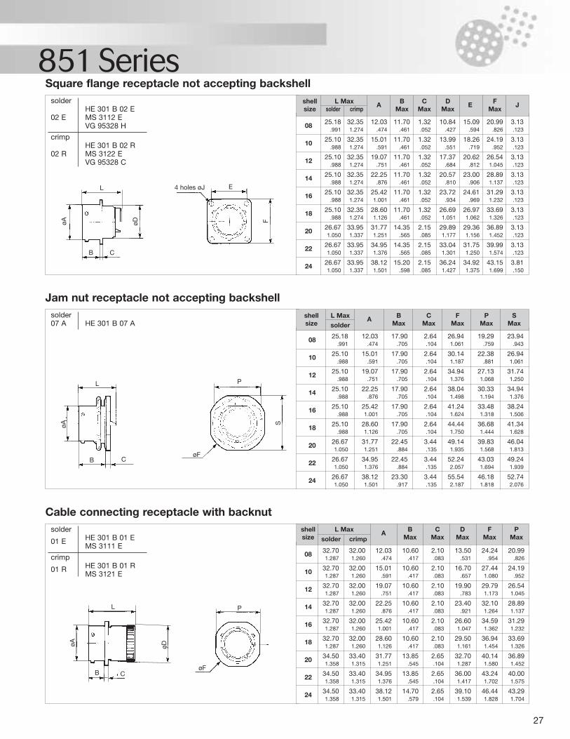
27
851 Seriessolder
HE 301 B 02 E02 E MS 3112 E
VG 95328 H
crimpHE 301 B 02 R
02 R MS 3122 EVG 95328 C
Square flange receptacle not accepting backshell
solder07 A HE 301 B 07 A
Jam nut receptacle not accepting backshell
solder
01 E HE 301 B 01 EMS 3111 E
crimp
01 R HE 301 B 01 RMS 3121 E
Cable connecting receptacle with backnut
08 25.18 32.35 12.03 11.70 1.32 10.84 15.09 20.99 3.13.991 1.274 .474 .461 .052 .427 .594 .826 .123
10 25.10 32.35 15.01 11.70 1.32 13.99 18.26 24.19 3.13.988 1.274 .591 .461 .052 .551 .719 .952 .123
12 25.10 32.35 19.07 11.70 1.32 17.37 20.62 26.54 3.13.988 1.274 .751 .461 .052 .684 .812 1.045 .123
14 25.10 32.35 22.25 11.70 1.32 20.57 23.00 28.89 3.13.988 1.274 .876 .461 .052 .810 .906 1.137 .123
16 25.10 32.35 25.42 11.70 1.32 23.72 24.61 31.29 3.13.988 1.274 1.001 .461 .052 .934 .969 1.232 .123
18 25.10 32.35 28.60 11.70 1.32 26.69 26.97 33.69 3.13.988 1.274 1.126 .461 .052 1.051 1.062 1.326 .123
20 26.67 33.95 31.77 14.35 2.15 29.89 29.36 36.89 3.131.050 1.337 1.251 .565 .085 1.177 1.156 1.452 .123
22 26.67 33.95 34.95 14.35 2.15 33.04 31.75 39.99 3.131.050 1.337 1.376 .565 .085 1.301 1.250 1.574 .123
24 26.67 33.95 38.12 15.20 2.15 36.24 34.92 43.15 3.811.050 1.337 1.501 .598 .085 1.427 1.375 1.699 .150
shell L Max A B C D E F Jsize solder crimp Max Max Max Max
08 25.18 12.03 17.90 2.64 26.94 19.29 23.94.991 .474 .705 .104 1.061 .759 .943
10 25.10 15.01 17.90 2.64 30.14 22.38 26.94.988 .591 .705 .104 1.187 .881 1.061
12 25.10 19.07 17.90 2.64 34.94 27.13 31.74.988 .751 .705 .104 1.376 1.068 1.250
14 25.10 22.25 17.90 2.64 38.04 30.33 34.94.988 .876 .705 .104 1.498 1.194 1.376
16 25.10 25.42 17.90 2.64 41.24 33.48 38.24.988 1.001 .705 .104 1.624 1.318 1.506
18 25.10 28.60 17.90 2.64 44.44 36.68 41.34.988 1.126 .705 .104 1.750 1.444 1.628
20 26.67 31.77 22.45 3.44 49.14 39.83 46.041.050 1.251 .884 .135 1.935 1.568 1.813
22 26.67 34.95 22.45 3.44 52.24 43.03 49.241.050 1.376 .884 .135 2.057 1.694 1.939
24 26.67 38.12 23.30 3.44 55.54 46.18 52.741.050 1.501 .917 .135 2.187 1.818 2.076
shell L Max A B C F P Ssize solder Max Max Max Max Max
08 32.70 32.00 12.03 10.60 2.10 13.50 24.24 20.991.287 1.260 .474 .417 .083 .531 .954 .826
10 32.70 32.00 15.01 10.60 2.10 16.70 27.44 24.191.287 1.260 .591 .417 .083 .657 1.080 .952
12 32.70 32.00 19.07 10.60 2.10 19.90 29.79 26.541.287 1.260 .751 .417 .083 .783 1.173 1.045
14 32.70 32.00 22.25 10.60 2.10 23.40 32.10 28.891.287 1.260 .876 .417 .083 .921 1.264 1.137
16 32.70 32.00 25.42 10.60 2.10 26.60 34.59 31.291.287 1.260 1.001 .417 .083 1.047 1.362 1.232
18 32.70 32.00 28.60 10.60 2.10 29.50 36.94 33.691.287 1.260 1.126 .417 .083 1.161 1.454 1.326
20 34.50 33.40 31.77 13.85 2.65 32.70 40.14 36.891.358 1.315 1.251 .545 .104 1.287 1.580 1.452
22 34.50 33.40 34.95 13.85 2.65 36.00 43.24 40.001.358 1.315 1.376 .545 .104 1.417 1.702 1.575
24 34.50 33.40 38.12 14.70 2.65 39.10 46.44 43.291.358 1.315 1.501 .579 .104 1.539 1.828 1.704
shell L Max A B C D F Psize solder crimp Max Max Max Max Max
L
øDøA F
E4 holes øJ
B C
L
øA S
P
B C
L P
øA øD
B CøF
øF
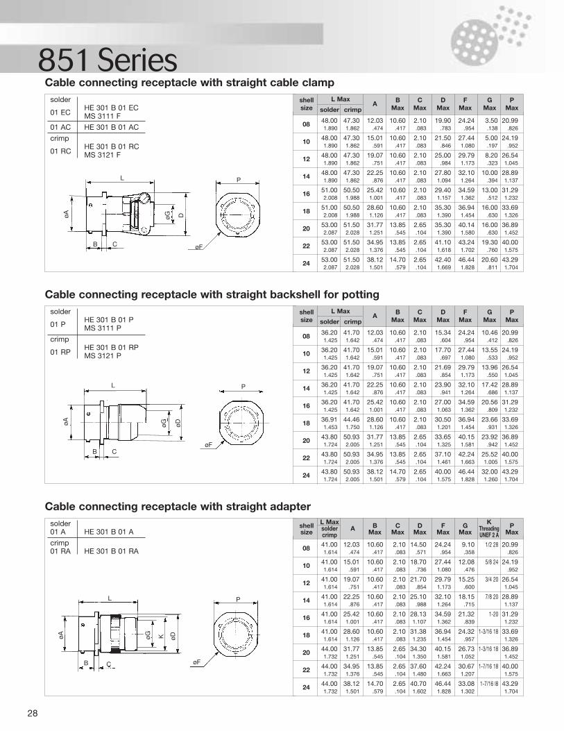
28
851 Seriessolder
HE 301 B 01 EC01 EC MS 3111 F
01 AC HE 301 B 01 AC
crimpHE 301 B 01 RC
01 RC MS 3121 F
Cable connecting receptacle with straight cable clamp
solderHE 301 B 01 P
01 P MS 3111 P
crimpHE 301 B 01 RP
01 RP MS 3121 P
Cable connecting receptacle with straight backshell for potting
08 36.20 41.70 12.03 10.60 2.10 15.34 24.24 10.46 20.991.425 1.642 .474 .417 .083 .604 .954 .412 .826
10 36.20 41.70 15.01 10.60 2.10 17.70 27.44 13.55 24.191.425 1.642 .591 .417 .083 .697 1.080 .533 .952
12 36.20 41.70 19.07 10.60 2.10 21.69 29.79 13.96 26.541.425 1.642 .751 .417 .083 .854 1.173 .550 1.045
14 36.20 41.70 22.25 10.60 2.10 23.90 32.10 17.42 28.891.425 1.642 .876 .417 .083 .941 1.264 .686 1.137
16 36.20 41.70 25.42 10.60 2.10 27.00 34.59 20.56 31.291.425 1.642 1.001 .417 .083 1.063 1.362 .809 1.232
18 36.91 44.46 28.60 10.60 2.10 30.50 36.94 23.66 33.691.453 1.750 1.126 .417 .083 1.201 1.454 .931 1.326
20 43.80 50.93 31.77 13.85 2.65 33.65 40.15 23.92 36.891.724 2.005 1.251 .545 .104 1.325 1.581 .942 1.452
22 43.80 50.93 34.95 13.85 2.65 37.10 42.24 25.52 40.001.724 2.005 1.376 .545 .104 1.461 1.663 1.005 1.575
24 43.80 50.93 38.12 14.70 2.65 40.00 46.44 32.00 43.291.724 2.005 1.501 .579 .104 1.575 1.828 1.260 1.704
shell L MaxA B C D F G P
size solder crimp Max Max Max Max Max Max
solder01 A HE 301 B 01 A
crimp01 RA HE 301 B 01 RA
Cable connecting receptacle with straight adapter
08 48.00 47.30 12.03 10.60 2.10 19.90 24.24 3.50 20.991.890 1.862 .474 .417 .083 .783 .954 .138 .826
10 48.00 47.30 15.01 10.60 2.10 21.50 27.44 5.00 24.191.890 1.862 .591 .417 .083 .846 1.080 .197 .952
12 48.00 47.30 19.07 10.60 2.10 25.00 29.79 8.20 26.541.890 1.862 .751 .417 .083 .984 1.173 .323 1.045
14 48.00 47.30 22.25 10.60 2.10 27.80 32.10 10.00 28.891.890 1.862 .876 .417 .083 1.094 1.264 .394 1.137
16 51.00 50.50 25.42 10.60 2.10 29.40 34.59 13.00 31.292.008 1.988 1.001 .417 .083 1.157 1.362 .512 1.232
18 51.00 50.50 28.60 10.60 2.10 35.30 36.94 16.00 33.692.008 1.988 1.126 .417 .083 1.390 1.454 .630 1.326
20 53.00 51.50 31.77 13.85 2.65 35.30 40.14 16.00 36.892.087 2.028 1.251 .545 .104 1.390 1.580 .630 1.452
22 53.00 51.50 34.95 13.85 2.65 41.10 43.24 19.30 40.002.087 2.028 1.376 .545 .104 1.618 1.702 .760 1.575
24 53.00 51.50 38.12 14.70 2.65 42.40 46.44 20.60 43.292.087 2.028 1.501 .579 .104 1.669 1.828 .811 1.704
shell L MaxA B C D F G P
size solder crimp Max Max Max Max Max Max
08 41.00 12.03 10.60 2.10 14.50 24.24 9.10 1/2 28 20.991.614 .474 .417 .083 .571 .954 .358 .826
10 41.00 15.01 10.60 2.10 18.70 27.44 12.08 5/8 24 24.191.614 .591 .417 .083 .736 1.080 .476 .952
12 41.00 19.07 10.60 2.10 21.70 29.79 15.25 3/4 20 26.541.614 .751 .417 .083 .854 1.173 .600 1.045
14 41.00 22.25 10.60 2.10 25.10 32.10 18.15 7/8 20 28.891.614 .876 .417 .083 .988 1.264 .715 1.137
16 41.00 25.42 10.60 2.10 28.13 34.59 21.32 1-20 31.291.614 1.001 .417 .083 1.107 1.362 .839 1.232
18 41.00 28.60 10.60 2.10 31.38 36.94 24.32 1-3/16 18 33.691.614 1.126 .417 .083 1.235 1.454 .957 1.326
20 44.00 31.77 13.85 2.65 34.30 40.15 26.73 1-3/16 18 36.891.732 1.251 .545 .104 1.350 1.581 1.052 1.452
22 44.00 34.95 13.85 2.65 37.60 42.24 30.67 1-7/16 18 40.001.732 1.376 .545 .104 1.480 1.663 1.207 1.575
24 44.00 38.12 14.70 2.65 40.70 46.44 33.08 1-7/16 l8 43.291.732 1.501 .579 .104 1.602 1.828 1.302 1.704
shell L Max B C D F G K Psize solder A Max Max Max Max Max Threading Maxcrimp UNEF 2 A
L
øDøA øG DP
øFB C
L
øA øG øD
P
øFB C
L
øA øG K øD
P
øFB C
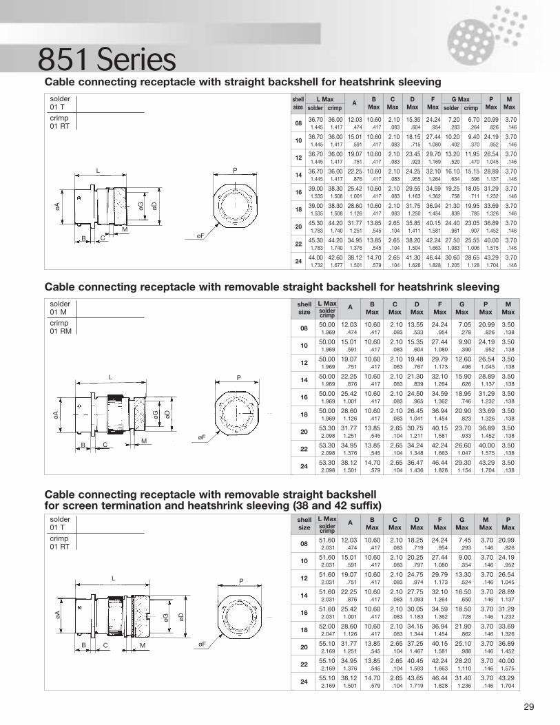
29
851 Seriessolder01 T
crimp01 RT
Cable connecting receptacle with straight backshell for heatshrink sleeving
08 36.70 36.00 12.03 10.60 2.10 15.35 24.24 7.20 6.70 20.99 3.701.445 1.417 .474 .417 .083 .604 .954 .283 .264 .826 .146
10 36.70 36.00 15.01 10.60 2.10 18.15 27.44 10.20 9.40 24.19 3.701.445 1.417 .591 .417 .083 .715 1.080 .402 .370 .952 .146
12 36.70 36.00 19.07 10.60 2.10 23.45 29.70 13.20 11.95 26.54 3.701.445 1.417 .751 .417 .083 .923 1.169 .520 .470 1.045 .146
14 36.70 36.00 22.25 10.60 2.10 24.25 32.10 16.10 15.15 28.89 3.701.445 1.417 .876 .417 .083 .955 1.264 .634 .596 1.137 .146
16 39.00 38.30 25.42 10.60 2.10 29.55 34.59 19.25 18.05 31.29 3.701.535 1.508 1.001 .417 .083 1.163 1.362 .758 .711 1.232 .146
18 39.00 38.30 28.60 10.60 2.10 31.75 36.94 21.30 19.95 33.69 3.701.535 1.508 1.126 .417 .083 1.250 1.454 .839 .785 1.326 .146
20 45.30 44.20 31.77 13.85 2.65 35.85 40.15 24.40 23.05 36.89 3.701.783 1.740 1.251 .545 .104 1.411 1.581 .961 .907 1.452 .146
22 45.30 44.20 34.95 13.85 2.65 38.20 42.24 27.50 25.55 40.00 3.701.783 1.740 1.376 .545 .104 1.504 1.663 1.083 1.006 1.575 .146
24 44.00 42.60 38.12 14.70 2.65 41.30 46.44 30.60 28.65 43.29 3.701.732 1.677 1.501 .579 .104 1.626 1.828 1.205 1.128 1.704 .146
shell L Max A B C D F G Max P Msize solder crimp Max Max Max Max solder crimp Max Max
solder01 M
crimp01 RM
Cable connecting receptacle with removable straight backshell for heatshrink sleeving
08 50.00 12.03 10.60 2.10 13.55 24.24 7.05 20.99 3.501.969 .474 .417 .083 .533 .954 .278 .826 .138
10 50.00 15.01 10.60 2.10 15.35 27.44 9.90 24.19 3.501.969 .591 .417 .083 .604 1.080 .390 .952 .138
12 50.00 19.07 10.60 2.10 19.48 29.79 12.60 26.54 3.501.969 .751 .417 .083 .767 1.173 .496 1.045 .138
14 50.00 22.25 10.60 2.10 21.30 32.10 15.90 28.89 3.501.969 .876 .417 .083 .839 1.264 .626 1.137 .138
16 50.00 25.42 10.60 2.10 24.50 34.59 18.95 31.29 3.501.969 1.001 .417 .083 .965 1.362 .746 1.232 .138
18 50.00 28.60 10.60 2.10 26.45 36.94 20.90 33.69 3.501.969 1.126 .417 .083 1.041 1.454 .823 1.326 .138
20 53.30 31.77 13.85 2.65 30.75 40.15 23.70 36.89 3.502.098 1.251 .545 .104 1.211 1.581 .933 1.452 .138
22 53.30 34.95 13.85 2.65 34.24 42.24 26.60 40.00 3.502.098 1.376 .545 .104 1.348 1.663 1.047 1.575 .138
24 53.30 38.12 14.70 2.65 36.47 46.44 29.30 43.29 3.502.098 1.501 .579 .104 1.436 1.828 1.154 1.704 .138
shell L Max A B C D F G P Msize solder Max Max Max Max Max Max Maxcrimp
solder01 T
crimp01 RT
Cable connecting receptacle with removable straight backshell for screen termination and heatshrink sleeving (38 and 42 suffix)
08 51.60 12.03 10.60 2.10 18.25 24.24 7.45 3.70 20.992.031 .474 .417 .083 .719 .954 .293 .146 .826
10 51.60 15.01 10.60 2.10 20.25 27.44 9.00 3.70 24.192.031 .591 .417 .083 .797 1.080 .354 .146 .952
12 51.60 19.07 10.60 2.10 24.75 29.79 13.30 3.70 26.542.031 .751 .417 .083 .974 1.173 .524 .146 1.045
14 51.60 22.25 10.60 2.10 27.75 32.10 16.50 3.70 28.892.031 .876 .417 .083 1.093 1.264 .650 .146 1.137
16 51.60 25.42 10.60 2.10 30.05 34.59 18.50 3.70 31.292.031 1.001 .417 .083 1.183 1.362 .728 .146 1.232
18 52.00 28.60 10.60 2.10 34.15 36.94 21.90 3.70 33.692.047 1.126 .417 .083 1.344 1.454 .862 .146 1.326
20 55.10 31.77 13.85 2.65 37.25 40.15 25.10 3.70 36.892.169 1.251 .545 .104 1.467 1.581 .988 .146 1.452
22 55.10 34.95 13.85 2.65 40.45 42.24 28.20 3.70 40.002.169 1.376 .545 .104 1.593 1.663 1.110 .146 1.575
24 55.10 38.12 14.70 2.65 43.65 46.44 31.40 3.70 43.292.169 1.501 .579 .104 1.719 1.828 1.236 .146 1.704
shell L Max A B C D F G M Psize solder Max Max Max Max Max Max Maxcrimp
L
øA øG øD
P
øFB CM
L
øA øG øD
P
øFB C
M
L
øA øG øD
P
øFB C M
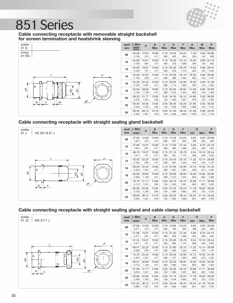
30
851 Seriessolder01 G
crimp01 RG
Cable connecting receptacle with removable straight backshell for screen termination and heatshrink sleeving
08 54.00 12.03 10.60 2.10 16.30 24.24 7.45 3.60 20.992.126 .474 .417 .083 .642 .954 .293 .142 .826
10 54.00 15.01 10.60 2.10 18.30 27.44 10.30 3.60 24.192.126 .591 .417 .083 .720 1.080 .406 .142 .952
12 54.00 19.07 10.60 2.10 22.30 29.79 13.20 3.60 26.542.126 .751 .417 .083 .878 1.173 .520 .142 1.045
14 54.00 22.25 10.60 2.10 25.30 32.10 16.50 3.60 28.892.126 .876 .417 .083 .996 1.264 .650 .142 1.137
16 54.00 25.42 10.60 2.10 28.30 34.59 19.35 3.60 31.292.126 1.001 .417 .083 1.114 1.362 .762 .142 1.232
18 54.00 28.60 10.60 2.10 32.30 36.94 21.60 3.60 33.692.126 1.126 .417 .083 1.272 1.454 .850 .142 1.326
20 59.30 31.77 13.85 2.65 34.30 40.15 24.80 3.60 36.892.335 1.251 .545 .104 1.350 1.581 .976 .142 1.452
22 59.30 34.95 13.85 2.65 38.30 42.24 27.90 3.60 40.002.335 1.376 .545 .104 1.508 1.663 1.098 .142 1.575
24 59.30 38.12 14.70 2.65 41.30 46.44 31.00 3.60 43.292.335 1.501 .579 .104 1.626 1.828 1.220 .142 1.704
shell L Max A B C D F G M Psize solder Max Max Max Max Max Max Maxcrimp
solder01 J HE 301 B 01 J
Cable connecting receptacle with straight sealing gland backshell
solder01 JC MS 3111 J
Cable connecting receptacle with straight sealing gland and cable clamp backshell
08 47.60 12.03 10.60 2.10 14.40 24.24 5.02 5.84 20.991.874 .474 .417 .083 .567 .954 .198 .230 .826
10 47.60 15.01 10.60 2.10 17.60 27.44 5.94 6.76 24.191.874 .591 .417 .083 .693 1.080 .234 .266 .952
12 48.70 19.07 10.60 2.10 21.10 29.79 9.34 10.16 26.541.917 .751 .417 .083 .831 1.173 .368 .400 1.045
14 53.50 22.25 10.60 2.10 24.40 32.10 11.32 12.14 28.892.106 .876 .417 .083 .961 1.264 .446 .478 1.137
16 59.00 25.42 10.60 2.10 27.60 34.59 14.73 15.55 31.292.323 1.001 .417 .083 1.087 1.362 .580 .612 1.232
18 65.00 28.60 10.60 2.10 30.80 36.94 16.00 16.82 33.692.559 1.126 .417 .083 1.213 1.454 .630 .662 1.326
20 79.10 31.77 13.85 2.65 34.10 40.15 16.89 17.71 36.893.114 1.251 .545 .104 1.343 1.581 .665 .697 1.452
22 80.00 34.95 13.85 2.65 37.30 42.24 17.78 18.60 40.003.150 1.376 .545 .104 1.469 1.663 .700 .732 1.575
24 90.00 38.12 14.70 2.65 40.50 46.44 20.34 21.16 43.293.543 1.501 .579 .104 1.594 1.828 .801 .833 1.704
shell L MaxA B C D F G P
size solder Max Max Max Max min Max Max
08 57.68 12.03 10.60 2.10 19.90 24.24 5.02 5.84 20.992.271 .474 .417 .083 .783 .954 .198 .230 .826
10 57.68 15.01 10.60 2.10 21.50 27.44 5.94 6.76 24.192.271 .591 .417 .083 .846 1.080 .234 .266 .952
12 61.24 19.07 10.60 2.10 25.00 29.79 9.34 10.16 26.542.411 .751 .417 .083 .984 1.173 .368 .400 1.045
14 66.01 22.25 10.60 2.10 27.80 32.10 11.32 12.14 28.892.599 .876 .417 .083 1.094 1.264 .446 .478 1.137
16 74.75 25.42 10.60 2.10 29.40 34.59 14.73 15.50 31.292.943 1.001 .417 .083 1.157 1.362 .580 .610 1.232
18 80.57 28.60 10.60 2.10 35.30 36.94 16.00 16.82 33.693.172 1.126 .417 .083 1.390 1.454 .630 .662 1.326
20 91.69 31.77 13.85 2.65 35.30 40.15 16.89 17.71 36.893.610 1.251 .545 .104 1.390 1.581 .665 .697 1.452
22 95.66 34.95 13.85 2.65 41.10 42.24 17.78 18.60 40.003.766 1.376 .545 .104 1.618 1.663 .700 .732 1.575
24 101.22 38.12 14.70 2.65 42.40 46.44 20.34 21.16 43.293.985 1.501 .579 .104 1.669 1.828 .801 .833 1.704
shell L MaxA B C D F G P
size solder Max Max Max Max min Max Max
L
øA øG øDP
øFB C M
L
øA øG øD
P
øFB C
L
øA øG øD
P
øFB C
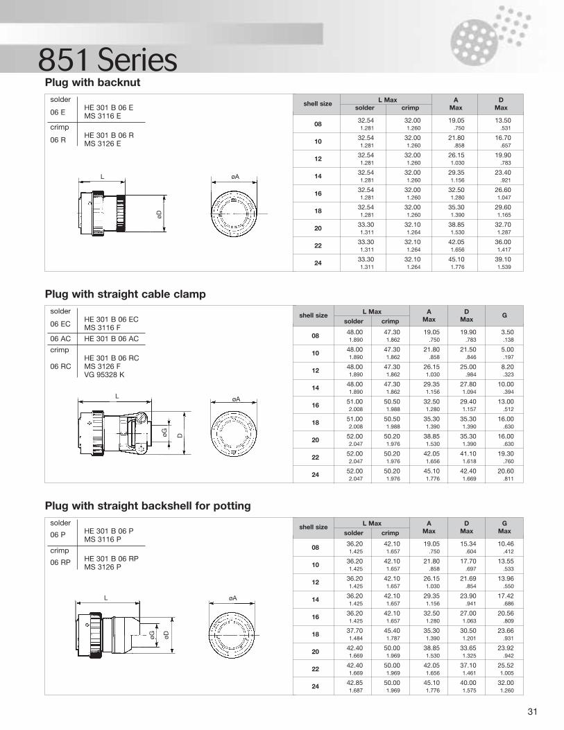
31
851 Seriessolder
HE 301 B 06 E06 E MS 3116 E
crimpHE 301 B 06 R
06 R MS 3126 E
Plug with backnut
solderHE 301 B 06 EC
06 EC MS 3116 F
06 AC HE 301 B 06 AC
crimpHE 301 B 06 RC
06 RC MS 3126 FVG 95328 K
Plug with straight cable clamp
solder
06 P HE 301 B 06 PMS 3116 P
crimp
06 RP HE 301 B 06 RPMS 3126 P
Plug with straight backshell for potting
08 32.54 32.00 19.05 13.501.281 1.260 .750 .531
10 32.54 32.00 21.80 16.701.281 1.260 .858 .657
12 32.54 32.00 26.15 19.901.281 1.260 1.030 .783
14 32.54 32.00 29.35 23.401.281 1.260 1.156 .921
16 32.54 32.00 32.50 26.601.281 1.260 1.280 1.047
18 32.54 32.00 35.30 29.601.281 1.260 1.390 1.165
20 33.30 32.10 38.85 32.701.311 1.264 1.530 1.287
22 33.30 32.10 42.05 36.001.311 1.264 1.656 1.417
24 33.30 32.10 45.10 39.101.311 1.264 1.776 1.539
shell size L Max A Dsolder crimp Max Max
08 48.00 47.30 19.05 19.90 3.501.890 1.862 .750 .783 .138
10 48.00 47.30 21.80 21.50 5.001.890 1.862 .858 .846 .197
12 48.00 47.30 26.15 25.00 8.201.890 1.862 1.030 .984 .323
14 48.00 47.30 29.35 27.80 10.001.890 1.862 1.156 1.094 .394
16 51.00 50.50 32.50 29.40 13.002.008 1.988 1.280 1.157 .512
18 51.00 50.50 35.30 35.30 16.002.008 1.988 1.390 1.390 .630
20 52.00 50.20 38.85 35.30 16.002.047 1.976 1.530 1.390 .630
22 52.00 50.20 42.05 41.10 19.302.047 1.976 1.656 1.618 .760
24 52.00 50.20 45.10 42.40 20.602.047 1.976 1.776 1.669 .811
shell size L Max A D Gsolder crimp Max Max
08 36.20 42.10 19.05 15.34 10.461.425 1.657 .750 .604 .412
10 36.20 42.10 21.80 17.70 13.551.425 1.657 .858 .697 .533
12 36.20 42.10 26.15 21.69 13.961.425 1.657 1.030 .854 .550
14 36.20 42.10 29.35 23.90 17.421.425 1.657 1.156 .941 .686
16 36.20 42.10 32.50 27.00 20.561.425 1.657 1.280 1.063 .809
18 37.70 45.40 35.30 30.50 23.661.484 1.787 1.390 1.201 .931
20 42.40 50.00 38.85 33.65 23.921.669 1.969 1.530 1.325 .942
22 42.40 50.00 42.05 37.10 25.521.669 1.969 1.656 1.461 1.005
24 42.85 50.00 45.10 40.00 32.001.687 1.969 1.776 1.575 1.260
shell size L Max A D Gsolder crimp Max Max Max
L øA
øD
L øA
øG D
L øA
øDøG
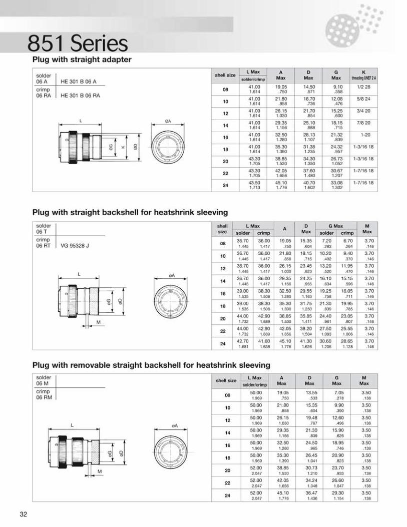
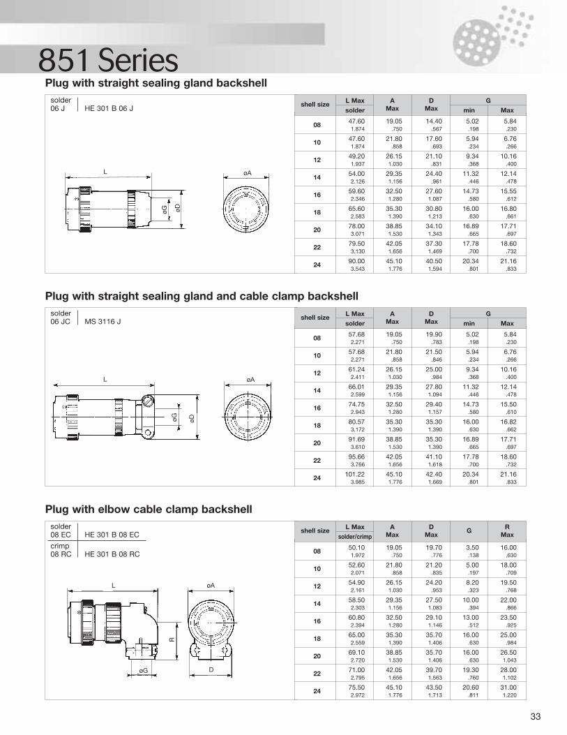
33
851 Seriessolder06 J HE 301 B 06 J
Plug with straight sealing gland backshell
solder06 JC MS 3116 J
Plug with straight sealing gland and cable clamp backshell
solder08 EC HE 301 B 08 EC
crimp08 RC HE 301 B 08 RC
Plug with elbow cable clamp backshell
08 50.10 19.05 19.70 3.50 16.001.972 .750 .776 .138 .630
10 52.60 21.80 21.20 5.00 18.002.071 .858 .835 .197 .709
12 54.90 26.15 24.20 8.20 19.502.161 1.030 .953 .323 .768
14 58.50 29.35 27.50 10.00 22.002.303 1.156 1.083 .394 .866
16 60.80 32.50 29.10 13.00 23.502.394 1.280 1.146 .512 .925
18 65.00 35.30 35.70 16.00 25.002.559 1.390 1.406 .630 .984
20 69.10 38.85 35.70 16.00 26.502.720 1.530 1.406 .630 1.043
22 71.00 42.05 39.70 19.30 28.002.795 1.656 1.563 .760 1.102
24 75.50 45.10 43.50 20.60 31.002.972 1.776 1.713 .811 1.220
shell size L Max A D G Rsolder/crimp Max Max Max
08 47.60 19.05 14.40 5.02 5.841.874 .750 .567 .198 .230
10 47.60 21.80 17.60 5.94 6.761.874 .858 .693 .234 .266
12 49.20 26.15 21.10 9.34 10.161.937 1.030 .831 .368 .400
14 54.00 29.35 24.40 11.32 12.142.126 1.156 .961 .446 .478
16 59.60 32.50 27.60 14.73 15.552.346 1.280 1.087 .580 .612
18 65.60 35.30 30.80 16.00 16.802.583 1.390 1.213 .630 .661
20 78.00 38.85 34.10 16.89 17.713.071 1.530 1.343 .665 .697
22 79.50 42.05 37.30 17.78 18.603.130 1.656 1.469 .700 .732
24 90.00 45.10 40.50 20.34 21.163.543 1.776 1.594 .801 .833
shell size L Max A D Gsolder Max Max min Max
08 57.68 19.05 19.90 5.02 5.842.271 .750 .783 .198 .230
10 57.68 21.80 21.50 5.94 6.762.271 .858 .846 .234 .266
12 61.24 26.15 25.00 9.34 10.162.411 1.030 .984 .368 .400
14 66.01 29.35 27.80 11.32 12.142.599 1.156 1.094 .446 .478
16 74.75 32.50 29.40 14.73 15.502.943 1.280 1.157 .580 .610
18 80.57 35.30 35.30 16.00 16.823.172 1.390 1.390 .630 .662
20 91.69 38.85 35.30 16.89 17.713.610 1.530 1.390 .665 .697
22 95.66 42.05 41.10 17.78 18.603.766 1.656 1.618 .700 .732
24 101.22 45.10 42.40 20.34 21.163.985 1.776 1.669 .801 .833
shell size L Max A D Gsolder Max Max min Max
L øAøDøG
L øA
øDøG
L øA
D
R
øG
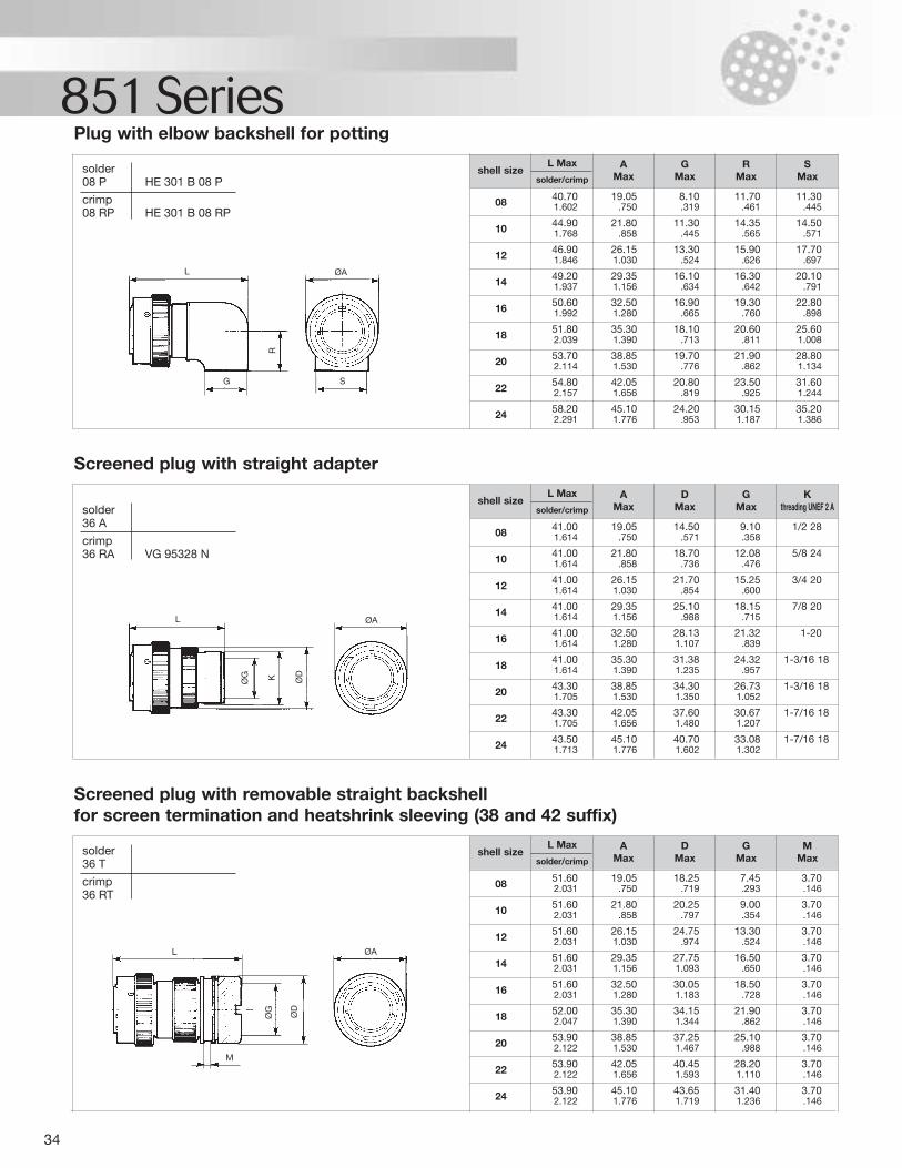
34
851 SeriesPlug with elbow backshell for potting
08 40.70 19.05 8.10 11.70 11.301.602 .750 .319 .461 .445
10 44.90 21.80 11.30 14.35 14.501.768 .858 .445 .565 .571
12 46.90 26.15 13.30 15.90 17.701.846 1.030 .524 .626 .697
14 49.20 29.35 16.10 16.30 20.101.937 1.156 .634 .642 .791
16 50.60 32.50 16.90 19.30 22.801.992 1.280 .665 .760 .898
18 51.80 35.30 18.10 20.60 25.602.039 1.390 .713 .811 1.008
20 53.70 38.85 19.70 21.90 28.802.114 1.530 .776 .862 1.134
22 54.80 42.05 20.80 23.50 31.602.157 1.656 .819 .925 1.244
24 58.20 45.10 24.20 30.15 35.202.291 1.776 .953 1.187 1.386
shell sizeL Max
solder/crimp
AMax
GMax
RMax
SMax
solder08 P HE 301 B 08 P
crimp08 RP HE 301 B 08 RP
solder36 T
crimp36 RT
solder36 A
crimp36 RA VG 95328 N
Screened plug with straight adapter
08 41.00 19.05 14.50 9.10 1/2 281.614 .750 .571 .358
10 41.00 21.80 18.70 12.08 5/8 241.614 .858 .736 .476
12 41.00 26.15 21.70 15.25 3/4 201.614 1.030 .854 .600
14 41.00 29.35 25.10 18.15 7/8 201.614 1.156 .988 .715
16 41.00 32.50 28.13 21.32 1-201.614 1.280 1.107 .839
18 41.00 35.30 31.38 24.32 1-3/16 181.614 1.390 1.235 .957
20 43.30 38.85 34.30 26.73 1-3/16 181.705 1.530 1.350 1.052
22 43.30 42.05 37.60 30.67 1-7/16 181.705 1.656 1.480 1.207
24 43.50 45.10 40.70 33.08 1-7/16 181.713 1.776 1.602 1.302
shell sizeL Max
solder/crimp
AMax
DMax
GMax
K threading UNEF 2 A
Screened plug with removable straight backshell for screen termination and heatshrink sleeving (38 and 42 suffix)
08 51.60 19.05 18.25 7.45 3.702.031 .750 .719 .293 .146
10 51.60 21.80 20.25 9.00 3.702.031 .858 .797 .354 .146
12 51.60 26.15 24.75 13.30 3.702.031 1.030 .974 .524 .146
14 51.60 29.35 27.75 16.50 3.702.031 1.156 1.093 .650 .146
16 51.60 32.50 30.05 18.50 3.702.031 1.280 1.183 .728 .146
18 52.00 35.30 34.15 21.90 3.702.047 1.390 1.344 .862 .146
20 53.90 38.85 37.25 25.10 3.702.122 1.530 1.467 .988 .146
22 53.90 42.05 40.45 28.20 3.702.122 1.656 1.593 1.110 .146
24 53.90 45.10 43.65 31.40 3.702.122 1.776 1.719 1.236 .146
shell sizeL Max
solder/crimp
AMax
DMax
GMax
MMax
L
L
L
M
KØG
ØD
ØG
ØD
G S
ØA
ØA
ØA
R
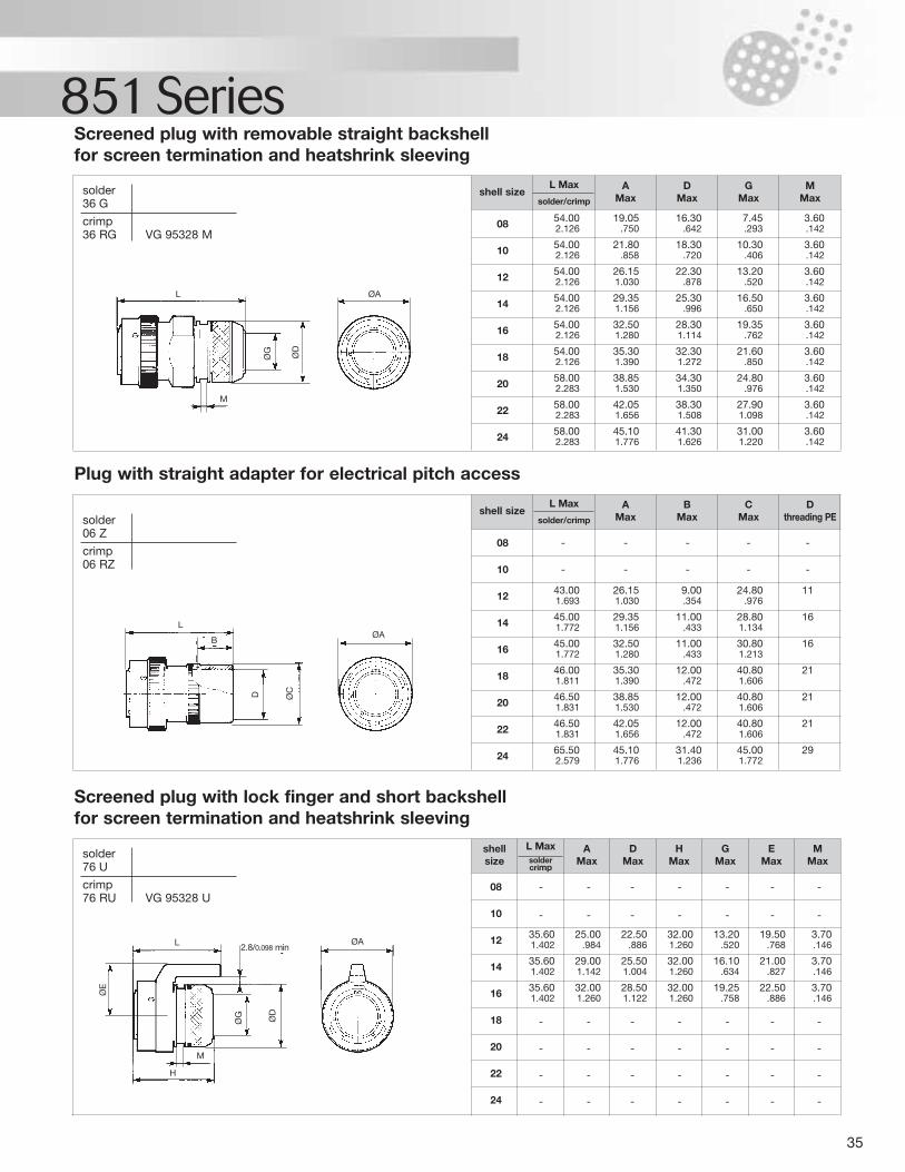
35
851 SeriesScreened plug with removable straight backshell for screen termination and heatshrink sleeving
08 54.00 19.05 16.30 7.45 3.602.126 .750 .642 .293 .142
10 54.00 21.80 18.30 10.30 3.602.126 .858 .720 .406 .142
12 54.00 26.15 22.30 13.20 3.602.126 1.030 .878 .520 .142
14 54.00 29.35 25.30 16.50 3.602.126 1.156 .996 .650 .142
16 54.00 32.50 28.30 19.35 3.602.126 1.280 1.114 .762 .142
18 54.00 35.30 32.30 21.60 3.602.126 1.390 1.272 .850 .142
20 58.00 38.85 34.30 24.80 3.602.283 1.530 1.350 .976 .142
22 58.00 42.05 38.30 27.90 3.602.283 1.656 1.508 1.098 .142
24 58.00 45.10 41.30 31.00 3.602.283 1.776 1.626 1.220 .142
shell sizeL Max
solder/crimp
AMax
DMax
GMax
MMax
solder36 G
crimp36 RG VG 95328 M
solder76 U
crimp76 RU VG 95328 U
solder06 Z
crimp06 RZ
Plug with straight adapter for electrical pitch access
08 - - - - -
10 - - - - -
12 43.00 26.15 9.00 24.80 111.693 1.030 .354 .976
14 45.00 29.35 11.00 28.80 161.772 1.156 .433 1.134
16 45.00 32.50 11.00 30.80 161.772 1.280 .433 1.213
18 46.00 35.30 12.00 40.80 211.811 1.390 .472 1.606
20 46.50 38.85 12.00 40.80 211.831 1.530 .472 1.606
22 46.50 42.05 12.00 40.80 211.831 1.656 .472 1.606
24 65.50 45.10 31.40 45.00 292.579 1.776 1.236 1.772
shell sizeL Max
solder/crimp
AMax
BMax
CMax
D threading PE
Screened plug with lock finger and short backshell for screen termination and heatshrink sleeving
08 - - - - - - -
10 - - - - - - -
12 35.60 25.00 22.50 32.00 13.20 19.50 3.701.402 .984 .886 1.260 .520 .768 .146
14 35.60 29.00 25.50 32.00 16.10 21.00 3.701.402 1.142 1.004 1.260 .634 .827 .146
16 35.60 32.00 28.50 32.00 19.25 22.50 3.701.402 1.260 1.122 1.260 .758 .886 .146
18 - - - - - - -
20 - - - - - - -
22 - - - - - - -
24 - - - - - - -
shellsize
L Maxsoldercrimp
AMax
DMax
HMax
GMax
EMax
MMax
2.8/0.098 min
ØG
ØCD
ØD
ØAL
M
LØA
ØA
ØD
ØG
ØE
L
H
M
B
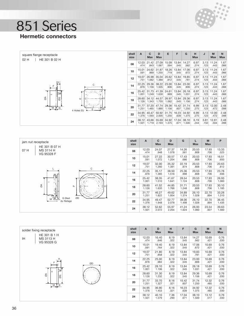
36
851 Series
square flange receptacle
02 H HE 301 B 02 H08 12.03 21.42 27.09 15.09 13.84 14.27 6.97 3.13 11.24 1.67
.474 .843 1.067 .594 .545 .562 .274 .123 .443 .066
10 15.01 24.62 31.87 18.26 13.84 17.06 6.97 3.13 11.24 1.67.591 .969 1.255 .719 .545 .672 .274 .123 .443 .066
12 19.07 26.98 35.04 20.62 13.84 19.85 6.97 3.13 11.24 1.67.751 1.062 1.380 .812 .545 .781 .274 .123 .443 .066
14 22.25 29.36 38.22 23.00 13.84 23.00 6.97 3.13 11.24 1.67.876 1.156 1.505 .906 .545 .906 .274 .123 .443 .066
16 25.42 31.73 41.39 24.61 13.84 26.18 6.97 3.13 11.24 1.671.001 1.249 1.630 .969 .545 1.031 .274 .123 .443 .066
18 28.60 34.12 44.57 26.97 13.84 29.36 6.97 3.13 11.24 1.671.126 1.343 1.755 1.062 .545 1.156 .274 .123 .443 .066
20 31.77 37.20 47.74 29.36 15.42 31.74 6.99 3.13 12.00 2.481.251 1.465 1.880 1.156 .607 1.250 .275 .123 .472 .098
22 34.95 40.47 50.92 31.75 16.23 34.92 6.99 3.13 12.00 2.481.376 1.593 2.005 1.250 .639 1.375 .275 .123 .472 .098
24 38.12 43.66 55.69 34.92 17.04 38.10 6.19 3.81 12.81 2.481.501 1.719 2.193 1.375 .671 1.500 .244 .150 .504 .098
shellsize
DMax
E F G HMax
J MMax
NMax
A CMax
Hermetic connectors
08 12.03 24.07 27.37 14.26 20.53 17.93 13.33.474 .948 1.078 .561 .808 .706 .525
10 15.01 27.22 30.57 17.43 20.53 17.93 16.51.591 1.072 1.204 .686 .808 .706 .650
12 19.07 32.00 35.32 22.19 20.53 17.93 20.63.751 1.260 1.391 .874 .808 .706 .812
14 22.25 35.17 38.50 25.36 20.53 17.93 23.78.876 1.385 1.516 .998 .808 .706 .936
16 25.42 38.35 41.67 28.54 20.53 17.93 26.931.001 1.510 1.641 1.124 .808 .706 1.060
18 28.60 41.52 44.85 31.71 20.53 17.93 30.101.126 1.635 1.766 1.248 .808 .706 1.185
20 31.77 46.27 49.62 34.89 26.10 22.70 33.281.251 1.822 1.954 1.374 1.028 .894 1.310
22 34.95 49.47 52.77 38.06 26.10 22.70 36.451.376 1.948 2.078 1.498 1.028 .894 1.435
24 38.12 52.62 55.97 41.24 26.93 23.54 39.631.501 2.072 2.204 1.624 1.060 .927 1.560
shellsize
CMax
A DMax
G LMax
MMax
P
08 12.03 16.40 8.19 13.84 14.27 10.69 0.76.474 .646 .322 .545 .562 .421 .030
10 15.01 19.40 8.19 13.84 17.06 10.69 0.76.591 .764 .322 .545 .672 .421 .030
12 19.07 21.80 8.19 13.84 19.83 10.69 0.76.751 .858 .322 .545 .781 .421 .030
14 22.25 25.00 8.19 13.84 23.00 10.69 0.76.876 .984 .322 .545 .906 .421 .030
16 25.42 28.10 8.19 13.84 26.18 10.69 0.761.001 1.106 .322 .545 1.031 .421 .030
18 28.60 31.30 8.19 13.84 29.36 10.69 0.761.126 1.232 .322 .545 1.156 .421 .030
20 31.77 33.70 8.16 15.42 31.74 12.32 0.761.251 1.327 .321 .607 1.250 .485 .030
22 34.95 36.90 8.16 16.23 34.92 12.32 0.761.376 1.453 .321 .639 1.375 .485 .030
24 38.12 40.10 7.36 17.04 38.10 13.12 0.761.501 1.579 .290 .671 1.500 .517 .030
shellsize
DMax
A HMax
F GMax
MMax
NMax
jam nut receptacle
HE 301 B 07 H07 H MS 3114 H
VG 95328 F
solder fixing receptacle
HE 301 B 1 HIH MS 3113 H
VG 95328 G
C
ØD
ØD
ØA
ØG
H
F
M N
ØA
L
M G Øextdu filetage
P C
F
M N
ØA
ØG
HC
E4 Holes ØJØD
E C
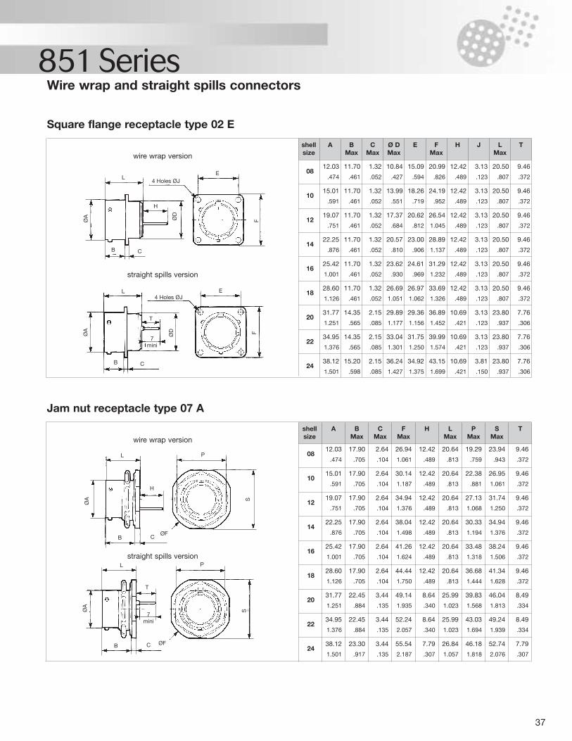
37
851 Series
wire wrap version
straight spills version
0812.03 11.70 1.32 10.84 15.09 20.99 12.42 3.13 20.50 9.46
.474 .461 .052 .427 .594 .826 .489 .123 .807 .372
1015.01 11.70 1.32 13.99 18.26 24.19 12.42 3.13 20.50 9.46
.591 .461 .052 .551 .719 .952 .489 .123 .807 .372
1219.07 11.70 1.32 17.37 20.62 26.54 12.42 3.13 20.50 9.46
.751 .461 .052 .684 .812 1.045 .489 .123 .807 .372
1422.25 11.70 1.32 20.57 23.00 28.89 12.42 3.13 20.50 9.46
.876 .461 .052 .810 .906 1.137 .489 .123 .807 .372
1625.42 11.70 1.32 23.62 24.61 31.29 12.42 3.13 20.50 9.46
1.001 .461 .052 .930 .969 1.232 .489 .123 .807 .372
1828.60 11.70 1.32 26.69 26.97 33.69 12.42 3.13 20.50 9.46
1.126 .461 .052 1.051 1.062 1.326 .489 .123 .807 .372
2031.77 14.35 2.15 29.89 29.36 36.89 10.69 3.13 23.80 7.76
1.251 .565 .085 1.177 1.156 1.452 .421 .123 .937 .306
2234.95 14.35 2.15 33.04 31.75 39.99 10.69 3.13 23.80 7.76
1.376 .565 .085 1.301 1.250 1.574 .421 .123 .937 .306
2438.12 15.20 2.15 36.24 34.92 43.15 10.69 3.81 23.80 7.76
1.501 .598 .085 1.427 1.375 1.699 .421 .150 .937 .306
shellsize
CMax
Ø DMax
E FMax
H J LMax
TA BMax
Wire wrap and straight spills connectors
Square flange receptacle type 02 E
wire wrap version
straight spills version
0812.03 17.90 2.64 26.94 12.42 20.64 19.29 23.94 9.46
.474 .705 .104 1.061 .489 .813 .759 .943 .372
1015.01 17.90 2.64 30.14 12.42 20.64 22.38 26.95 9.46
.591 .705 .104 1.187 .489 .813 .881 1.061 .372
1219.07 17.90 2.64 34.94 12.42 20.64 27.13 31.74 9.46
.751 .705 .104 1.376 .489 .813 1.068 1.250 .372
1422.25 17.90 2.64 38.04 12.42 20.64 30.33 34.94 9.46
.876 .705 .104 1.498 .489 .813 1.194 1.376 .372
1625.42 17.90 2.64 41.26 12.42 20.64 33.48 38.24 9.46
1.001 .705 .104 1.624 .489 .813 1.318 1.506 .372
1828.60 17.90 2.64 44.44 12.42 20.64 36.68 41.34 9.46
1.126 .705 .104 1.750 .489 .813 1.444 1.628 .372
2031.77 22.45 3.44 49.14 8.64 25.99 39.83 46.04 8.49
1.251 .884 .135 1.935 .340 1.023 1.568 1.813 .334
2234.95 22.45 3.44 52.24 8.64 25.99 43.03 49.24 8.49
1.376 .884 .135 2.057 .340 1.023 1.694 1.939 .334
2438.12 23.30 3.44 55.54 7.79 26.84 46.18 52.74 7.79
1.501 .917 .135 2.187 .307 1.057 1.818 2.076 .307
shellsize
A BMax
CMax
FMax
H LMax
PMax
SMax
T
Jam nut receptacle type 07 A
4 Holes ØJ
4 Holes ØJ
E
E
L
L
P
ØF
ØF
L
H
B C
B C
ØA
ØA
SS
PL
H
T
T
7mini
7mini
CB
CB
ØA
ØA
ØD
ØD
FF
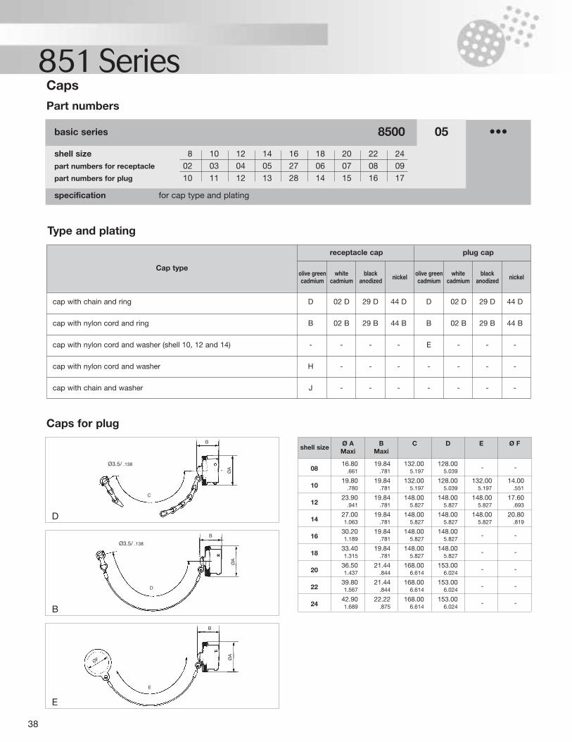
38
851 Series
specification for cap type and plating
shell size 8 10 12 14 16 18 20 22 24part numbers for receptacle 02 03 04 05 27 06 07 08 09part numbers for plug 10 11 12 13 28 14 15 16 17
basic series 8500 05 •••
Part numbers
Caps
Type and plating
Cap type
receptacle cap plug cap
cap with chain and ring D 02 D 29 D 44 D D 02 D 29 D 44 D
cap with nylon cord and ring B 02 B 29 B 44 B B 02 B 29 B 44 B
cap with nylon cord and washer (shell 10, 12 and 14) - - - - E - - -
cap with nylon cord and washer H - - - - - - -
cap with chain and washer J - - - - - - -
olive greencadmium
whitecadmium
black anodized nickel olive green
cadmiumwhite
cadmiumblack
anodized nickel
0816.80 19.84 132.00 128.00 - -
.661 .781 5.197 5.039
1019.80 19.84 132.00 128.00 132.00 14.00
.780 .781 5.197 5.039 5.197 .551
1223.90 19.84 148.00 148.00 148.00 17.60
.941 .781 5.827 5.827 5.827 .693
1427.00 19.84 148.00 148.00 148.00 20.801.063 .781 5.827 5.827 5.827 .819
1630.20 19.84 148.00 148.00 - -1.189 .781 5.827 5.827
1833.40 19.84 148.00 148.00 - -1.315 .781 5.827 5.827
2036.50 21.44 168.00 153.00 - -1.437 .844 6.614 6.024
2239.80 21.44 168.00 153.00 - -1.567 .844 6.614 6.024
2442.90 22.22 168.00 153.00 - -1.689 .875 6.614 6.024
shell sizeØ AMaxi
BMaxi
C D E Ø F
Caps for plug
D
B
E
Ø3.5/ .138
C
B
B
D
E
ØF
B
ØA
ØA
ØA
Ø3.5/ .138
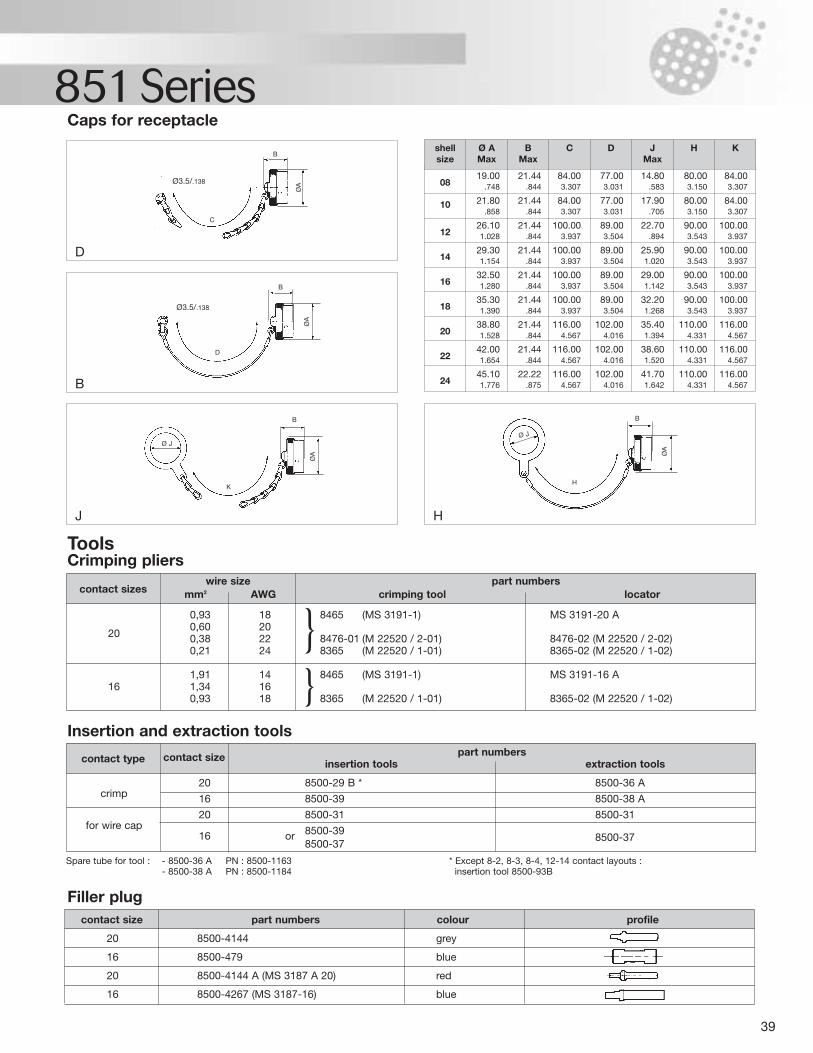
39
851 Series
0819.00 21.44 84.00 77.00 14.80 80.00 84.00
.748 .844 3.307 3.031 .583 3.150 3.307
10 21.80 21.44 84.00 77.00 17.90 80.00 84.00.858 .844 3.307 3.031 .705 3.150 3.307
1226.10 21.44 100.00 89.00 22.70 90.00 100.001.028 .844 3.937 3.504 .894 3.543 3.937
1429.30 21.44 100.00 89.00 25.90 90.00 100.001.154 .844 3.937 3.504 1.020 3.543 3.937
1632.50 21.44 100.00 89.00 29.00 90.00 100.001.280 .844 3.937 3.504 1.142 3.543 3.937
1835.30 21.44 100.00 89.00 32.20 90.00 100.001.390 .844 3.937 3.504 1.268 3.543 3.937
2038.80 21.44 116.00 102.00 35.40 110.00 116.001.528 .844 4.567 4.016 1.394 4.331 4.567
2242.00 21.44 116.00 102.00 38.60 110.00 116.001.654 .844 4.567 4.016 1.520 4.331 4.567
2445.10 22.22 116.00 102.00 41.70 110.00 116.001.776 .875 4.567 4.016 1.642 4.331 4.567
Caps for receptacle
D
B
J H
0,93 18 8465 (MS 3191-1) MS 3191-20 A0,60 20
20 0,38 22 8476-01 (M 22520 / 2-01) 8476-02 (M 22520 / 2-02)0,21 24 8365 (M 22520 / 1-01) 8365-02 (M 22520 / 1-02)
1,91 14 8465 (MS 3191-1) MS 3191-16 A16 1,34 16
0,93 18 8365 (M 22520 / 1-01) 8365-02 (M 22520 / 1-02)
contact sizeswire size
mm2 AWGpart numbers
crimping tool locator
ToolsCrimping pliers
20 8500-29 B * 8500-36 Acrimp 16 8500-39 8500-38 A
20 8500-31 8500-31for wire cap
16 or 8500-398500-37
8500-37
contact type contact size part numbersinsertion tools extraction tools
Insertion and extraction tools
20 8500-4144 grey
16 8500-479 blue
20 8500-4144 A (MS 3187 A 20) red
16 8500-4267 (MS 3187-16) blue
contact size part numbers colour profile
Filler plug
shell Ø A B C D J H Ksize Max Max Max
Spare tube for tool : - 8500-36 A PN : 8500-1163 * Except 8-2, 8-3, 8-4, 12-14 contact layouts :- 8500-38 A PN : 8500-1184 insertion tool 8500-93B
Ø3.5/.138
C
D
B
B
KH
B B
ØA Ø
A
Ø JØ J
ØA
ØA
Ø3.5/.138
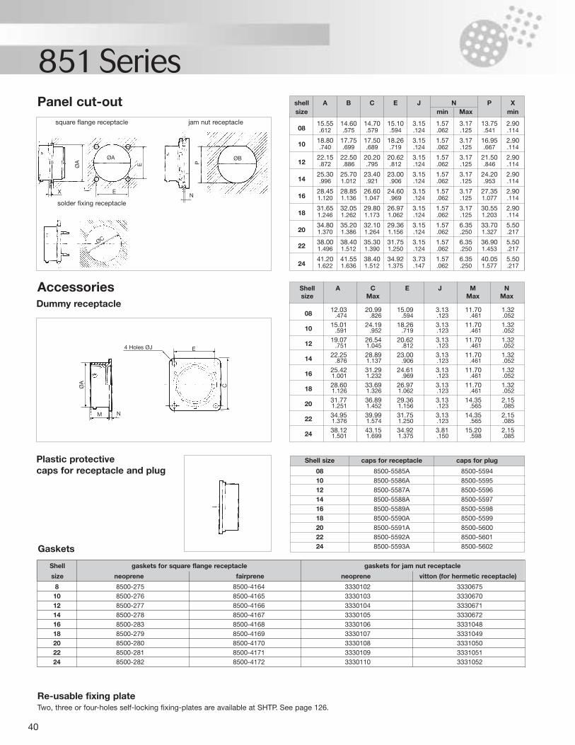
40
851 Series
0815.55 14.60 14.70 15.10 3.15 1.57 3.17 13.75 2.90.612 .575 .579 .594 .124 .062 .125 .541 .114
10 18.80 17.75 17.50 18.26 3.15 1.57 3.17 16.95 2.90.740 .699 .689 .719 .124 .062 .125 .667 .114
1222.15 22.50 20.20 20.62 3.15 1.57 3.17 21.50 2.90.872 .886 .795 .812 .124 .062 .125 .846 .114
1425.30 25.70 23.40 23.00 3.15 1.57 3.17 24.20 2.90.996 1.012 .921 .906 .124 .062 .125 .953 .114
1628.45 28.85 26.60 24.60 3.15 1.57 3.17 27.35 2.901.120 1.136 1.047 .969 .124 .062 .125 1.077 .114
1831.65 32.05 29.80 26.97 3.15 1.57 3.17 30.55 2.901.246 1.262 1.173 1.062 .124 .062 .125 1.203 .114
2034.80 35.20 32.10 29.36 3.15 1.57 6.35 33.70 5.501.370 1.386 1.264 1.156 .124 .062 .250 1.327 .217
22 38.00 38.40 35.30 31.75 3.15 1.57 6.35 36.90 5.501.496 1.512 1.390 1.250 .124 .062 .250 1.453 .217
2441.20 41.55 38.40 34.92 3.73 1.57 6.35 40.05 5.501.622 1.636 1.512 1.375 .147 .062 .250 1.577 .217
Panel cut-out
Accessories
shell A B C E J N P X size min Max min
08 12.03 20.99 15.09 3.13 11.70 1.32.474 .826 .594 .123 .461 .052
10 15.01 24.19 18.26 3.13 11.70 1.32.591 .952 .719 .123 .461 .052
12 19.07 26.54 20.62 3.13 11.70 1.32.751 1.045 .812 .123 .461 .052
14 22.25 28.89 23.00 3.13 11.70 1.32.876 1.137 .906 .123 .461 .052
16 25.42 31.29 24.61 3.13 11.70 1.321.001 1.232 .969 .123 .461 .052
18 28.60 33.69 26.97 3.13 11.70 1.321.126 1.326 1.062 .123 .461 .052
20 31.77 36.89 29.36 3.13 14.35 2.151.251 1.452 1.156 .123 .565 .085
22 34.95 39.99 31.75 3.13 14.35 2.151.376 1.574 1.250 .123 .565 .085
24 38.12 43.15 34.92 3.81 15.20 2.151.501 1.699 1.375 .150 .598 .085
Shell A C E J M Nsize Max Max Max
8 8500-275 8500-4164 3330102 333067510 8500-276 8500-4165 3330103 333067012 8500-277 8500-4166 3330104 333067114 8500-278 8500-4167 3330105 333067216 8500-283 8500-4168 3330106 333104818 8500-279 8500-4169 3330107 333104920 8500-280 8500-4170 3330108 333105022 8500-281 8500-4171 3330109 333105124 8500-282 8500-4172 3330110 3331052
Shell gaskets for square flange receptacle gaskets for jam nut receptacle
size neoprene fairprene neoprene vitton (for hermetic receptacle)
Gaskets
08 8500-5585A 8500-559410 8500-5586A 8500-559512 8500-5587A 8500-559614 8500-5588A 8500-559716 8500-5589A 8500-559818 8500-5590A 8500-559920 8500-5591A 8500-560022 8500-5592A 8500-560124 8500-5593A 8500-5602
Shell size caps for receptacle caps for plug
Dummy receptacle
Plastic protective caps for receptacle and plug
square flange receptacle jam nut receptacle
solder fixing receptacle
ØA
ØC
ØB
E
M N
E4 Holes ØJ
ØA C
XN
ØA E P
Re-usable fixing plateTwo, three or four-holes self-locking fixing-plates are available at SHTP. See page 126.
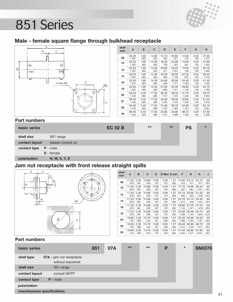
41
851 Series
manufactures specifications
polarization N, W, X, Y, Z
contact type P - maleS - female
Male - female square flange through bulkhead receptacle
contact layout please consult us
shell size 851 range
basic series EC 52 B ** ** PS *
Part numbers
contact type P - male
contact layout consult SHTP
Jam nut receptacle with front release straight spills
shell size 851 range
shell type 07A - jam nut receptaclewithout backshell
basic series 851 07A ** ** P * SN0378
Part numbers
0833.20 1.60 14.30 15.10 20.60 12.00 3.20 27.301.307 .063 .563 .594 .811 .472 .126 1.075
10 33.20 1.60 14.30 18.30 23.80 15.00 3.20 31.801.307 .063 .563 .720 .937 .591 .126 1.252
1233.20 1.60 14.30 20.60 26.20 19.05 3.20 35.101.307 .063 .563 .811 1.031 .750 .126 1.382
1433.20 1.60 14.30 23.00 28.60 22.23 3.20 38.501.307 .063 .563 .906 1.126 .875 .126 1.516
1633.20 1.60 14.30 24.60 30.90 25.40 3.20 41.301.307 .063 .563 .969 1.217 1.000 .126 1.626
1833.20 1.60 14.30 27.00 33.30 28.60 3.20 44.701.307 .063 .563 1.063 1.311 1.126 .126 1.760
2036.40 2.40 17.50 29.40 36.50 31.75 3.20 49.101.433 .094 .689 1.157 1.437 1.250 .126 1.933
2136.40 2.40 17.50 30.60 38.50 33.85 3.20 51.201.433 .094 .689 1.205 1.516 1.333 .126 2.016
2236.40 2.40 17.50 31.80 39.70 34.90 3.20 53.101.433 .094 .689 1.252 1.563 1.374 .126 2.091
2436.40 2.40 17.50 34.90 42.90 38.10 4.20 57.301.433 .094 .689 1.374 1.689 1.500 .165 2.256
shellA B C D E F G Hsize
0817.25 2.30 13.68 5.00 5.00 1.57 14.60 23.15 23.15 .60
.679 .091 .539 .197 .197 .062 .575 .911 .911 .024
10 17.25 2.30 13.68 5.00 5.00 1.57 17.70 16.80 26.45 .60.679 .091 .539 .197 .197 .062 .697 .661 1.041 .024
1217.25 2.30 13.68 5.00 5.00 1.57 22.70 20.90 31.20 .60
.679 .091 .539 .197 .197 .062 .894 .823 1.228 .024
1417.25 2.30 13.68 5.00 5.00 1.57 25.70 24.10 34.40 .60
.679 .091 .539 .197 .197 .062 1.012 .949 1.354 .024
1617.25 2.30 13.68 5.00 5.00 1.57 28.80 27.20 37.55 .60
.679 .091 .539 .197 .197 .062 1.134 1.071 1.478 .024
1817.25 2.30 13.68 5.00 5.00 1.57 32.00 30.40 40.75 .60
.679 .091 .539 .197 .197 .026 1.260 1.197 1.604 0.24
2018.85 2.50 13.79 5.00 6.60 1.57 35.20 33.60 45.50 .60
.742 .098 .543 .197 .260 .062 1.386 1.323 1.791 .024
2218.55 2.50 13.79 5.00 6.60 1.57 38.40 36.80 48.70 .60
.742 .098 .543 .197 .260 .062 1.512 1.449 1.917 .024
2418.85 2.50 13.79 5.00 5.90 1.57 41.50 39.90 51.85 .60
.742 .098 .543 .197 .232 .062 1.634 1.571 2.041 .024
shellA B C D E Max E min F G H Jsize
polarization
A
C
D4 holes ØG
A C
D
B
EØH
GØF
ØJ
E
ØH
B
ØF