Sounding of the Atmosphere using Broadband Emission ...
14
Utah State University Utah State University DigitalCommons@USU DigitalCommons@USU Space Dynamics Lab Publications Space Dynamics Lab 1-1-2006 Sounding of the Atmosphere using Broadband Emission Sounding of the Atmosphere using Broadband Emission Radiometry (SABER): Sensor Design, Performance, and Lessons Radiometry (SABER): Sensor Design, Performance, and Lessons Learned Learned Steven B. Brown Mark Jensen Scott Jensen Glen Hansen Lorin Zollinger Roy Esplin See next page for additional authors Follow this and additional works at: https://digitalcommons.usu.edu/sdl_pubs Recommended Citation Recommended Citation Brown, Steven B.; Jensen, Mark; Jensen, Scott; Hansen, Glen; Zollinger, Lorin; Esplin, Roy; and Miller, James B., "Sounding of the Atmosphere using Broadband Emission Radiometry (SABER): Sensor Design, Performance, and Lessons Learned" (2006). Space Dynamics Lab Publications. Paper 24. https://digitalcommons.usu.edu/sdl_pubs/24 This Article is brought to you for free and open access by the Space Dynamics Lab at DigitalCommons@USU. It has been accepted for inclusion in Space Dynamics Lab Publications by an authorized administrator of DigitalCommons@USU. For more information, please contact [email protected].
Transcript of Sounding of the Atmosphere using Broadband Emission ...

Utah State University Utah State University
DigitalCommons@USU DigitalCommons@USU
Space Dynamics Lab Publications Space Dynamics Lab
1-1-2006
Sounding of the Atmosphere using Broadband Emission Sounding of the Atmosphere using Broadband Emission
Radiometry (SABER): Sensor Design, Performance, and Lessons Radiometry (SABER): Sensor Design, Performance, and Lessons
Learned Learned
Steven B. Brown
Mark Jensen
Scott Jensen
Glen Hansen
Lorin Zollinger
Roy Esplin
See next page for additional authors
Follow this and additional works at: https://digitalcommons.usu.edu/sdl_pubs
Recommended Citation Recommended Citation Brown, Steven B.; Jensen, Mark; Jensen, Scott; Hansen, Glen; Zollinger, Lorin; Esplin, Roy; and Miller, James B., "Sounding of the Atmosphere using Broadband Emission Radiometry (SABER): Sensor Design, Performance, and Lessons Learned" (2006). Space Dynamics Lab Publications. Paper 24. https://digitalcommons.usu.edu/sdl_pubs/24
This Article is brought to you for free and open access by the Space Dynamics Lab at DigitalCommons@USU. It has been accepted for inclusion in Space Dynamics Lab Publications by an authorized administrator of DigitalCommons@USU. For more information, please contact [email protected].

Authors Authors Steven B. Brown, Mark Jensen, Scott Jensen, Glen Hansen, Lorin Zollinger, Roy Esplin, and James B. Miller
This article is available at DigitalCommons@USU: https://digitalcommons.usu.edu/sdl_pubs/24

Sounding of the Atmosphere using Broadband Emission Radiometry (SABER): Sensor design, performance, and lessons learned
Authors: Steven B. Brown1, Mark Jensen1, Scott Jensen1, Glen Hansen1, Lorin Zollinger1, Roy Esplin1, James B Miller2
1Space Dynamics Laboratory, Utah State University, 1695 N. Research Park Way, N. Logan, UT 84341-1947, Tel. (435) 797-4600, Fax: (435) 797-4475, email: [email protected]
2NASA Langley Research Center, 11 Langley Blvd., Hampton, VA 23681-2199, Tel. (757) 864-7101, Fax (757) 864-6003, [email protected]
ABSTRACT The Sounding of the Atmosphere using Broadband Emission Radiometry (SABER) instrument, a 10-channel infrared (1.27 - 16.9 µm) radiometer, was launched on the TIMED (Thermosphere, Ionosphere, Mesosphere Energetics and Dynamics) satellite in December 2001 from Vandenburg Air Force Base. SABER is being used to measure earthlimb emissions and to characterize infrared radiation, allowing calculation of cooling rates and determination of composition and temperature profiles in the mesosphere, lower thermosphere, and ionosphere (60-180 km). The SABER telescope is an on-axis Cassegrain design with a picket-fence tuning fork chopper at the first focus and a clamshell re-imager to focus the image on the focal plane. The telescope was designed to reject stray light from the Earth and atmosphere outside the instrument’s instantaneous field-of-view (IFOV). The baffle assembly contains a single-axis scan mirror, which permits the 2 km vertical IFOV of each detector to be scanned from the Earth to a 400 km tangent height. The telescope and baffle assembly are cooled to 220 K by a dedicated radiator. The focal plane assembly is cooled to 75 K by a miniature cryogenic refrigerator. Field programmable gate arrays are used to implement state machine algorithms for control and operation of the instrument and subsystems. Although originally designed for a two-year lifetime requirement, the SABER instrument has been in continuous operation since January 2002. This paper discusses the SABER instrument design and innovations developed to achieve the required performance, along with instrument performance and lessons learned from the program.
Keywords: SABER, TIMED, FiST
1.0 INTRODUCTION The Sounding of the Atmosphere using Broadband Emission Radiometry (SABER) instrument was built, tested, and calibrated by the Space Dynamics Laboratory/Utah State University Research Foundation (SDL). SABER was launched as a payload on the Thermosphere, Ionosphere, Mesosphere, Energetics and Dynamics (TIMED) spacecraft on 7 December 2001, and is currently operating in a 625-km circular orbit and a 74° inclination. Designed to operate for 2 years, SABER has now successfully collected data for over 4 years.
The objective of the SABER program is to improve our understanding of fundamental processes in the mesosphere and lower thermosphere, including thermal structure, the Oy, HOy, NOy chemistry, the energetics and distribution of radiatively active species, dynamics and transport processes, and important polar processes1. The mesosphere and lower thermosphere have been relatively unexplored because measuring processes in these regions on a global scale requires a highly sensitive instrument with high off-axis rejection capability. The SABER instrument was designed to meet the high radiometric sensitivity, operational flexibility, and long experiment life required for these studies.
To achieve the high radiometric sensitivity, operational flexibility, and long experiment life required for the SABER program, SDL designed the instrument with state-of-the-art mechanical cooling, high off-axis rejection capability, high pointing accuracy, and low electrical noise.
2.0 SABER INSTRUMENT DESCRIPTION OVERVIEW The SABER instrument, shown in Fig. 1, is a 10-channel earthlimb-viewing sensor that measures atmospheric emissions in the spectral range of 1.27 µm to 16.9 µm. A high off-axis rejection telescope collects wanted light and discriminates against unwanted light. A single-axis scan mirror scans the instrument field of view vertically across the earthlimb to produce vertical spectral radiance profiles of the mesosphere and lower thermosphere. A large baffle, designed to
Infrared Spaceborne Remote Sensing XIV, edited by Marija Strojnik, Proc. of SPIEVol. 6297, 62970U, (2006) · 0277-786X/06/$15 · doi: 10.1117/12.684137
Proc. of SPIE Vol. 6297 62970U-1
Downloaded From: http://proceedings.spiedigitallibrary.org/ on 08/29/2014 Terms of Use: http://spiedl.org/terms
bdarrington
Typewritten Text
Brown, Steven B., Mark Jensen, Scott Jensen, Glen Hansen, Lorin Zollinger, Roy Esplin, and James B. Miller. 2006. "Sounding of the Atmosphere Using Broadband Emission Radiometry (SABER): Sensor Design, Performance, and Lessons Learned." Proceedings of SPIE 6297:62970U. doi:10.1117/12.684137.

I
maximize stray light rejection, is located in front of the scan mirror, and allows the center of SABER’s 1.4-degree wide field of view to be scanned across depression angles from 11.2 to 26.2 degrees. Ten discrete detectors mounted on a focal plane array (FPA) each give a vertical footprint on the earthlimb of about 2 km for a 60-km tangent height look angle and 625-km orbit. Instrument specifications are detailed in SABER Instrument Requirements Document1.
Fig. 1. SABER instrument without MLI blanketing.
Fig. 2 is a schematic of the SABER instrument configuration. The main subassemblies include: telescope and associated optics, focal plane assembly, scan mirror assembly, baffle assembly, thermal assemblies, and electronics.
Fig. 2. SABER instrument configuration (cross sectional view).
Scan MirrorAssembly
ApertureCover
Scan MirrorBaffleAssembly
IFCBlackbody
Mirror M1
Fore OpticsAssembly
Mirror M3
Mirror M4
Re-imager OpticsAssembly
Mirror M2
FPA AssemblyThermal Link
TelescopeSupportStrut
S/CInterfacePlate
InstrumentElectronicsBox
Refrigerator Mount
Refrigerator
AlignmentCube
JonesSources
.
Proc. of SPIE Vol. 6297 62970U-2
Downloaded From: http://proceedings.spiedigitallibrary.org/ on 08/29/2014 Terms of Use: http://spiedl.org/terms

2.1 Telescope and Optics
The SABER optical system is an on-axis Cassegrain design that consists of a single-axis scan mirror, a two-mirror on-axis Cassegrain configuration telescope, a picket-fence tuning-fork chopper, a two-mirror clamshell re-imager, 10 passband filters, 10 discrete detectors, baffles, and a three-dimensional Lyot stop.
The single-axis scan mirror scans the line of sight of the 10 detectors across the earth, the earthlimb, into cold space, and onto an in-flight calibrator (IFC). Mirrors M1 and M2, located in the fore optics assembly, focus input light onto an intermediate focal plane where the chopper modulates light from within the field of view and blocks light from outside the field of view. The two shutters of the tuning-fork chopper are similar in principle to two parallel picket fences, which when translated relative to each other modulate the light that passes through both fences. The chopper shutters have 10 openings at the locations that are imaged by the clamshell optics onto the 10 discrete detectors. The picket-fence design minimizes the required chopper motion, which maximizes chopper reliability and makes it possible to chop at frequencies above the 1/f noise knee of the HgCdTe detector. The two-mirror (M3 and M4) re-imager is a clamshell configuration and re-images the light passing through the holes in the chopper shutter onto the 10 discrete detectors.
Fig. 3 shows the layout of the 10 discrete detectors. Each detector is covered with an individual optical bandpass filter that limits the spectral bandwidth of light reaching the detector, resulting in the unique passbands. The filter thicknesses and the detector heights were adjusted to correct for longitudinal chromatic aberration. Each detector has an instantaneous field of view (IFOV) of 0.7 by 10 mrad, resulting in a 0.7-mrad angular detector width. A flexible thermal link couples the detectors to the cryocooler cold block.
Fig. 3. SABER FPA layout.
The Lyot stop is positioned directly over the detector assembly and prevents the detectors from seeing any part of the SABER instrument that is warmer than the detector assembly except for the mirrors and chopper shutters. The mirrors and the chopper shutters are gold coated and hence have low emissivity values.
An expendable aperture cover was used to protect the optics from contamination during ground and launch operations. To eject the cover, a wax-actuator pulled a pin that held the cover in place. Springs gently pushed the cover away from the radiator plate, exposing the telescope aperture.
2.2 Scan Mirror
A single-axis scan mirror scans the instrument field of view vertically across the earthlimb. This mirror permits the 2-km vertical IFOV of each detector, referenced to 60 km to be scanned from below the horizon to ensure coverage all the way to the ground to a 400-km tangent height, which provides a cold space measurement for calibration. Accurate vertical registration of the tangent height of the atmospheric data is achieved by analyzing the 14.9 and 15.2 µm CO2 channels. While making a measurement the SABER instrument scans the field of view of the focal plane vertically through the atmosphere from about 3 km below the horizon to a tangent height of 200 km, taking into account instrument and spacecraft uncertainties. The scan rate provides 5 samples in every 2 km of scan motion at 60 km tangent height.
The scan mirror operates in two data taking modes: an acquisition mode that locates the region of the earthlimb to be measured by overscanning, and an adaptive mode that maximizes data-taking efficiency by locking onto the required measurement region and reducing the scan amplitude. When in the adaptive mode, the scan mirror is rotated about 90
Proc. of SPIE Vol. 6297 62970U-3
Downloaded From: http://proceedings.spiedigitallibrary.org/ on 08/29/2014 Terms of Use: http://spiedl.org/terms

degrees to view the full aperture, in-flight calibrator (IFC) blackbody and cold space every other scan cycle. This approach provides in-flight calibration of the long wavelength channels. Less frequently tungsten lamps located within the blackbody are illuminated during the IFC view to provide a reference to the short wavelengths. This in-flight calibration system provides correction for changes in instrument responsivity and offset caused by changing conditions such as changes in the temperature of the telescope, focal plane, and electronics as well as optical transmission changes. The cold space measurement provides a measurement of the instrument offset.
2.3 Electronics
SABER has electronic controllers for the refrigerator, scan mirror, mechanical chopper, calibration sources, operational heaters, and the cover release. The SABER electronics also include the signal processing circuitry, a command and data handling subsystem (C&DH), housekeeping and monitor electronics, and a power distribution subsystem. The command decoder and system controller are state machines implemented in programmable logic. This approach offers radiation hardness and minimized costly software efforts.
The electrical signals from the 10 detectors are amplified and synchronously demodulated by means of 10 phase-lock amplifiers that are synchronized with the chopper. The demodulated outputs from the phase-lock amplifiers are multiplexed through a single analog-to-digital converter. The digitized data are then formatted together with housekeeping data and placed in output buffers to be picked up by the spacecraft by means of a 1553 electrical interface.
2.4 Thermal Subsystems
There are three separate temperature zones on the SABER instrument: the telescope, electronics, and focal plane assembly zones. These zones are shown in Fig. 4. The telescope temperature zone consists of relay optics, the scanner assembly, the IFC blackbody, and the baffle assembly. The electronics temperature zone consists of the SABER control electronics, the miniature cryogenic refrigerator (cryocooler), the cryocooler control electronics, and support structure. The focal plane assembly (FPA) zone requires precise temperature control and includes the focal planes and the cold linkages.
The telescope zone operates between 208 and 250 K. A dedicated passive radiator plate that looks into deep space past the earthlimb is used to cool the telescope to reduce photon noise, reduce the heat load on the refrigerator, and to minimize the temperature of the full aperture blackbody. The spacecraft is maneuvered so that the radiator and aperture, parallel to the orbital plane, are never exposed to direct sunlight. The telescope is thermally isolated from the warmer SABER support structure and the TIMED spacecraft bus by thermal blankets and telescope support struts.
The electronics temperature zone operates between 240 K and 270 K. Because the reject temperature of the cryocooler plays an important role in the overall cooling capacity of the cryocooler, precise control of the cryocooler reject temperature was needed. The SABER control electronics can operate under a wide range of temperatures without significantly affecting their performance. The support structure provides the mechanical interface to the spacecraft and also serves as the passive radiator to reject heat. The electronics boxes and the refrigerator are attached to the instrument mounting plate that is cooled to between 250 K and 300 K by the spacecraft.
The FPA temperature zone is cooled to 75 K to reduce photon noise and thermally generated noise in the detectors using a miniature cryogenic pulse-tube refrigerator.
3.0 DESIGN INNOVATIONS The SABER instrument presented several design challenges to meet the mass and thermal balance requirements. In addition, new innovations were required to allow operation of the focal plane at 75 K while maintaining structural stiffness and optical alignment. Thermal and mechanical considerations as well as the stringent stray light rejection requirements presented challenges for the optical design. A purge system was necessary to maintain adequate cleanliness levels for stray light and also to prevent buildup of moisture in thermal blanket materials within the telescope. Operation of the scan mechanism at 220 K required special attention to bearing lubrication, materials, and encoder electronics. A number of features were designed into the electronics to obtain the required noise equivalent response from the detectors and signal processing electronics.
Proc. of SPIE Vol. 6297 62970U-4
Downloaded From: http://proceedings.spiedigitallibrary.org/ on 08/29/2014 Terms of Use: http://spiedl.org/terms

Fig. 4. SABER temperature zones.
3.1 Thermal/Mechanical Design
There were two critical requirements for the focal plane temperature zone: the FPA had to be cooled to less than 75 K to ensure adequate detector sensitivity and noise performance, and the FPA needed to maintain precise optical alignment over the life of the mission. Failure in either of these areas would have resulted in degraded science or possibly complete mission failure.
Maintaining the SABER focal plane at cryogenic temperatures (75 K) was critical to obtain the required sensitivity and signal-to-noise ratio of the SABER mission. Traditionally, cryogens such as liquid helium or solid hydrogen have been used to cool focal planes to these temperatures. However, to meet the operational life and mass requirements for the SABER mission, cryogens could not be used.
To cool the detectors to this temperature, the cooler needed to be reliable, have low input power, small size, and low mass. The TRW miniature pulse tube cryocooler, shown in Fig. 5, met these requirements. A design temperature difference of 3 K from the detectors to the cryocooler cold block required the cold block to run at 72 K because the detectors are required to run at 75 K. To connect the cold block of the cooler to the FPA, SDL developed a solderless flexible thermal link technology, which thermally connected the cooler to the detectors while providing a high degree of mechanical isolation. The thermal link is essentially 100% thermally efficient, which means that the thermal performance is comparable to a solid cross section of the same material. Static flexibilities (stiffness) of the link were measured and found to be lower than 0.1 N/mm in all axes.
The limited cooling capacity of the cryocooler required that the FPA be thermally isolated from its surroundings. SDL developed the Fiber Support Technology (FiST), shown in Fig 6., to successfully reduce the conductive parasitic heat loads to less than 4 mW. The mechanical stiffness of the system was also greatly enhanced using the FiST, with a first natural resonant frequency well above 500 Hz.
Thermal requirements for the telescope drove the material thickness of the structure. The heat at the back of the instrument, where the detectors were located, had to move along the re-imager optics and fore optics assemblies, then into the scan mirror housing, and finally down the baffle assembly to a radiator mounted at its entrance. The radiator also provided all of the hardware to attach the aperture cover to protect the optics from contamination.
Telescope Radiator
Interface Temp. (208/235 K)
Electronics/Refrigerator Radiator Interface Temp. (240/265 K)
FPA Temperature Zone (75 K)
RefrigeratorMount
Temperature(250/270 K)
Avg. Telescope Temperature (215/250 K) Zone1
Zone2
Zone1
Zone2
Zone3
Proc. of SPIE Vol. 6297 62970U-5
Downloaded From: http://proceedings.spiedigitallibrary.org/ on 08/29/2014 Terms of Use: http://spiedl.org/terms

Fig. 5. SABER TRW miniature pulse tube cryocooler. Fig 6. SABER flight FiST unit.
The SABER telescope and focal planes also needed to be thermally isolated from the heat loads of the electronics to maintain the required temperatures. This was accomplished by placing six telescope support struts, made from G10 tubes, between the telescope and the spacecraft interface plate. These G10 tubes not only provided thermal isolation, but also provided the support mechanism for the telescope. The assembly and integration of these tubes with the telescope and spacecraft interface plate presented its own challenges. Because of the compound angles the tubes formed, there was justified concern that stress could be induced into the structure holding the optical components. This stress in turn could cause misalignment of the optics. To eliminate this possibility, the re-imager housing was bolted to its mounting cradles that also provided the socket for one end of the tubes. The end fittings that provided the socket for the other end of the tubes were bolted to the spacecraft interface plate. The tubes were then inserted into the sockets on each end and careful measurements made to ensure that the re-imager housing was properly aligned. The tubes were then bonded in place and a final alignment check was performed to verify that the housing was still properly aligned.
An access hole in the front of the spacecraft interface plate allowed the electronics box to be inserted after all of the optics had been integrated and aligned. The front of the electronics box provided a radiator surface to reject the heat generated. The electronics box was designed to allow the radiator plate to be removed, providing access to the PC boards. This allowed board removal even when SABER was mounted to the spacecraft, but access to the cable connectors was not possible without removing the instrument from the spacecraft.
The spacecraft interface plate not only provided the means for supporting the telescope, but also the means for supporting and rejecting the heat from the miniature pulse tube cryocooler used to cool the detectors. The spacecraft interface plate also provided the mounting scheme for bolting SABER to the TIMED spacecraft. Six G10 isolators were used to thermally isolate SABER from TIMED; four in the front and two in the bottom of the spacecraft interface plate. Titanium bolts secured SABER to TIMED. Integration of SABER with the TIMED spacecraft was a very simple process. A specially designed handling fixture supported SABER while it was inserted into the spacecraft and bolted down. Once it was secure, electrical cables were mated and the N2 purge line secured. The N2 was used to keep the optics from becoming contaminated with water and particulates. After attaching SABER to its handling fixture, the process of mounting it to TIMED required about 15 minutes.
3.2 Optics and Stray Light Rejection
Measuring processes in the mesosphere and lower thermosphere atmospheric regions required SABER to be a highly sensitive instrument with high off-axis rejection capability. To meet this requirement, the SABER telescope was designed to reject stray light from the Earth and atmosphere outside the instrument’s instantaneous field-of-view (IFOV).
Baffling and other stray light rejection features of the design were carefully optimized. The stray light performance of this on-axis optical design was shown by both analysis and experimental measurement to be as good as an off-axis design2. This exceptional stray light rejection performance for an on-axis optical design was achieved principally by using a novel three-dimensional Lyot stop in a re-imaging optical configuration with super-polished aluminum mirrors
Proc. of SPIE Vol. 6297 62970U-6
Downloaded From: http://proceedings.spiedigitallibrary.org/ on 08/29/2014 Terms of Use: http://spiedl.org/terms
for the pointing and telescope mirrors. The two clamshell mirrors are polished aluminum, which minimizes the obscurations due to the central holes in the clamshell that allow the entry and exiting of light. If nickel-plated mirrors had been used, the nickel plating necessary on the mirror edges would have increased the obscurations due to the clamshell holes. The surface roughness of the clamshell mirrors does not need to be as good as the mirrors in front of the chopper because these mirrors are not illuminated by bright off-axis sources. Therefore, polished aluminum mirrors could be used for the clamshell and still meet the stray light requirements.
The three-dimensional Lyot stop consists of a central obscuration mounted on 3 tapered struts. The outer edge of the secondary conical baffle is imaged at the plane of the Lyot stop central obscuration. This image is smaller than the Lyot stop central obscuration so the inner edge of the entrance pupil annulus is determined by the Lyot stop and not by the secondary conical baffle. The limiting vane in the main baffle, which is located close to the primary mirror, is imaged in the plane of the Lyot stop outer diameter. This image is larger than the outer diameter of the Lyot stop so the outer edge of the entrance pupil annulus is determined by the Lyot stop and not by the limiting vane in the main baffle. The three struts that support the secondary mirror run from near the plane of the primary mirror to behind the secondary so the images of the vanes that support the secondary mirror are imaged on the Lyot stop struts. These images are narrower than the Lyot stop struts so the Lyot stop struts rather than the secondary mirror struts determined the radial edges of the three entrance pupil segments.
SDL measured the off-axis response of the SABER instrument at visible wavelengths in September 1998, which is representative of SABER’s short wavelength channels. The resulting off-axis response was compared to an APART model conducted at 0.4 µm, which is the peak response of the visible detector. The measurement validated the stray light design and complemented the APART software model, which predicted that mirror scatter is the dominant stray light mechanism at short wavelengths. The off-axis response measurement indicated that SABER is an exceptional stray light suppression telescope2.
3.3 Purge System
Because of the stray light rejection requirements of the SABER optical system, it was necessary to minimize accumulation of particulates on the scan, primary, and secondary mirrors. To reduce any scatter due to mirror contamination, SDL designed a purge system into the SABER instrument that was used during all pre-flight activities, including integration, test, shipping, and storage. This system provided a means for routing clean dry nitrogen gas into the instrument. The gas was vented out of the instrument through vents provided for decompression during the ascent from the launch pad to orbit. The purge system prevented build up of hydrocarbon deposits on the optics, provided a clean method of restoring the instrument to atmospheric pressure following thermal/vacuum chamber tests, and reduced the buildup of water molecules in the thermal blankets surrounding the focal plane.
3.4 Scan Mirror and Bearings
To meet mission objectives, the scan mechanism needed to operate between 215 K and 240 K, with its minimum temperature requirement being limited by the motor/encoder that drives the scan mirror. The motor/encoder assembly, supplied by BEI Precision Systems and Space Division, consists of a 3-phase brushless DC motor manufactured by Kollmorgen Inland Motor, and an optical encoder built by BEI. The optical encoder, which provides position feedback, is a 3-channel encoder, with two 18-bit incremental channels and one index channel. Combining the outputs of both incremental channels and counting every output transition provides 20 bits total resolution. The rms-measured accuracy over 360° of rotation on the flight encoder is better than 1 arc-second for each channel.
The scan mechanism bearings, manufactured by Barden, are duplex pairs on each end of the scan shaft. One duplex pair is built into the motor/encoder. This duplex pair of bearings is configured in a back-to-back configuration with a spacer in between the bearings to maximize the moment stiffness of the system. The other duplex pair is located on the other end of the shaft and configured as a face-to-face pair. This configuration reduced any stress that may be induced into the shaft due to temperature differences from one side of the scan housing to the other, or other stresses that may occur.
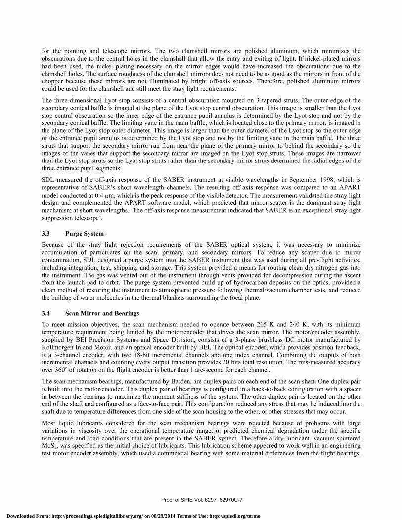
Most liquid lubricants considered for the scan mechanism bearings were rejected because of problems with large variations in viscosity over the operational temperature range, or predicted chemical degradation under the specific temperature and load conditions that are present in the SABER system. Therefore a dry lubricant, vacuum-sputtered MoS2, was specified as the initial choice of lubricants. This lubrication scheme appeared to work well in an engineering test motor encoder assembly, which used a commercial bearing with some material differences from the flight bearings.
Proc. of SPIE Vol. 6297 62970U-7
Downloaded From: http://proceedings.spiedigitallibrary.org/ on 08/29/2014 Terms of Use: http://spiedl.org/terms

However, during early testing of the flight unit, microscopic inspection of the bearings revealed a residue attached to the balls and races. Chemical analysis of the residue indicated that a chemical reaction between the sulfur in the lubricant and the copper in the bearing retainers occurred, forming copper sulfate crystals that acted like sand in the bearings.
On the recommendation from the Tribology and Surface Science Branch at Lewis Research Center, a contract was negotiated with AEA Technology to apply ion-plated lead to the races of the new bearings. AEA Technology also manufactured leaded bronze cages for the bearings and developed and conducted a run-in test. This solution offered some compromises to using the MoS2 lubrication. The ion-coated lead lubrication has a demonstrated long life but with an increase in total torque and in torque noise. The ion-coated lead bearings also work best in a vacuum and must be protected from air as the oxygen in air forms a layer of lead oxide on the lubricant. Some deterioration of the lubricating film occurs during operation in air. This deterioration is considered recoverable if operation is kept to less than 100,000 revolutions and rotation speeds are limited to less than 100 rpm. Under these conditions the film deterioration fully recovers when operated in a vacuum.3
3.5 Electronics
Mission requirements that drove the SABER electronics design included low measurement noise, large data measurement dynamic range, low cost, long mission life, autonomous operation running 24-7, spacecraft communications via MIL-STD-1553, minimize telemetry requirements, meet modified MIL-STD-461B EMI/EMC requirement
The measurement noise requirement for SABER, 3 counts rms for the data channels using a 4.3 Hz bandwidth sampled at 22.73 times per second, implied noise contributions from the electronics that are well below the limiting noise performance of the infrared detectors or the photon noise in the incident background radiation. Low noise electronics became the main driver to the electronics design. Mass, complexity, and EEE parts were traded to ensure this requirement was met.
Extra shielding in the electronics box and cabling was used to prevent noise coupling. Quiet measurement electronics were separated from noisier subsystems for grounding and isolation concerns, along with using massive low-impedance grounds and power distribution conductors. The data channel preamps received further isolation and conditioned power to prevent noise coupling.
Low bandwidth EEE parts were selected to eliminate potential response and undesirable behavior at high bandwidths, which might result in greater noise. Logic devices with slow transition times were used and switched with slow clocks at 1 MHz for all logic except the 16 MHz clock for the MIL-STD-1553 interface to the spacecraft. The switching clocks of DC/DC converters supplying power for the signal processing subsystem were synchronized with the A/D conversions of the measurement data ensuring no transients would occur during digitization.
Care was taken to reject external noise contributors from the spacecraft and other instruments. Spacecraft shielding and grounding concepts were rigorously followed.
To eliminate photoconductive detector 1/f noise in the measurement data required an optical chopped signal that modulated the 4.3 Hz data channel information bandwidth around the chopper frequency of 1 kHz. This placed the measurement bandwidth high enough in frequency away from the detector 1/f noise. At the same time, design of the photovoltaic preamps was done in such a way that high frequency voltage noise would not corrupt the 1 kHz chopped measurement signal. The optical chopper requirement employed a lock-in amplifier technique using coherent rectification or DC restoration of the measurement bandwidth data in order to process the data for digitization.
The measurement dynamic range of all the SABER data channels was quite large. The largest channel was channel 9, which had a range from the noise threshold to the maximum signal in excess of 6.7 × 10⁵, requiring 21 bits of digital data. This ruled out implementing the signal processing chain with a digital approach. The sensitivity of 3 counts rms was not required at larger measurement signals allowing a 12-bit analog-to-digital converter (A/D) to be used in combination with analog gain switching stages to achieve the required dynamic range. The analog implementation of the measurement data signal processing chain also realized a savings in power consumption from a digital processing approach. Low power EEE parts were also used to reduce power consumption. Low power usually means low bandwidth in analog electronics, which helps in the noise reduction efforts.
The large dynamic range and large optical background on the detectors made it necessary to incorporate an offset adjustment feature so a changing optical background over the mission could be cancelled.
Proc. of SPIE Vol. 6297 62970U-8
Downloaded From: http://proceedings.spiedigitallibrary.org/ on 08/29/2014 Terms of Use: http://spiedl.org/terms

Simple electrical design concepts were embraced to minimize costs in the SABER instrument design. State-machine controllers were used instead of microprocessors to control all functions, including the command and data handling (C&DH) functions. State-machine controllers are designed to perform very specific functions and do not have both hardware and software concerns, which simplifies their design, fabrication, testing, and verification, and also reduces cost. At the same time, flexibility was built into the C&DH controller to adapt to changing conditions in the space environment.
The SABER C&DH subsystem worked well as a state-machine controller because requirements of how the instrument operated were well defined early in the design stage and did not change once it was in orbit. In addition, actions were repetitious, such as collecting the same set of data over and over and controlling the same sequence of events over and over. Control of the system is easily broken into pieces and is located away from the centralized or main controller.
EMC/EMI testing to MIL-STD-461B requirements was conducted early in the electronics development using engineering prototype circuits and simulated loads. This proved to be very useful in pointing to possible EMC/EMI problems for the flight system early enough in the design to make necessary modifications without large effects on costs and schedules.
4.0 INSTRUMENT PERFORMANCE
4.1 Preflight Performance Tests
The SABER instrument was subjected to proto-flight acceptance tests as SDL prior to integration into the spacecraft. These tests demonstrated that the SABER instrument complied with the requirements of the SABER Instrument Requirements Document1 and the contract statement of work4. Most of the proto-flight acceptance tests were performed at the integrated instrument level and included functional, performance, environmental, and calibration tests5. The proto-flight test levels were called out in the TIMED Component Environment Specification Document6, and demonstrated that the design and workmanship met the requirements with margin.
Spacecraft integration and tests were successfully completed at the Johns Hopkins University Applied Physics Laboratory and Goddard Space Flight Center by February 2000. Before launch, the integrated TIMED spacecraft and instruments were subjected to two storage periods during which the entire spacecraft was enclosed in an environmentally controlled container. During these storage periods the SABER instrument was kept under a constant dry nitrogen gas purge to maintain optical cleanliness and to keep the total build-up of water vapor in the multi-layer thermal (MLI) blankets to a minimum.
Table 1 lists the four basic functional test procedures developed and used throughout SABER testing. These tests fell into two test configurations and two levels of functionality. The abbreviated functional tests (warm and cold) were developed to provide a representative subset of commands to each subsystem that allowed trending data to be collected and system health to be verified. The full functional tests (warm and cold) were used to demonstrate complete compliance and functionality of the instrument to all commands and conditions. Final verification that the instrument met requirements was demonstrated during cold full functional tests.
Table 1. SABER functional tests.
Test Configuration Test Functionality Ambient Temperature and
Pressure Environment Space-Like Thermal/Vacuum
Environment Test a subset of functions to verify subsystem operation
Abbreviated warm functional test Abbreviated cold functional test
Thorough test of all functions for each subsystem to certify full operation and compliance
Warm full functional test procedure Cold full functional test procedure
Proc. of SPIE Vol. 6297 62970U-9
Downloaded From: http://proceedings.spiedigitallibrary.org/ on 08/29/2014 Terms of Use: http://spiedl.org/terms
4.2 Flight Operational Performance
The SABER instrument has been in nearly continuous operation since its launch in December 2001, and is currently taking excellent science data. There have been no indications of decreased functionality or overall performance during the time it has been in flight operations, other than the need to periodically warm the focal plane to remove a small film of water ice, which is described in Section 5.0. Thermal performance closely matches the thermal model developed for the instrument during design and environmental tests. The system meets or exceeds all measurement requirements and has operated in conjunction with the spacecraft and the other instruments that are on the spacecraft.
4.2.1 Thermal Performance
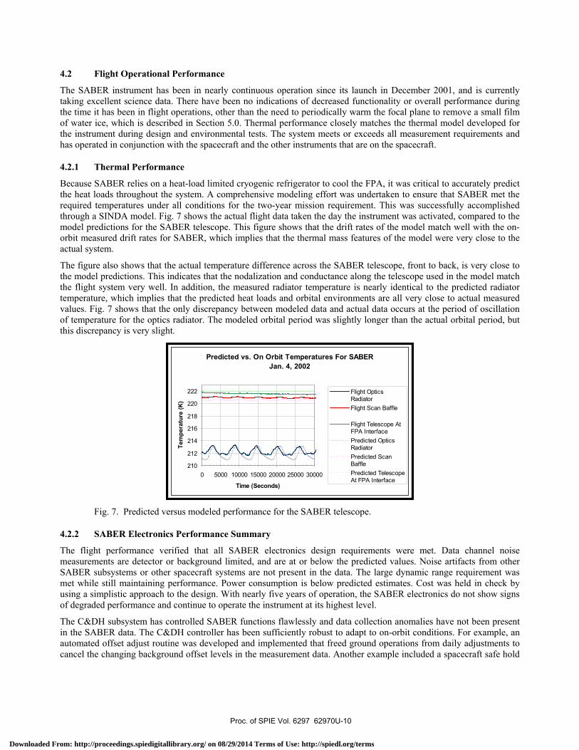
Because SABER relies on a heat-load limited cryogenic refrigerator to cool the FPA, it was critical to accurately predict the heat loads throughout the system. A comprehensive modeling effort was undertaken to ensure that SABER met the required temperatures under all conditions for the two-year mission requirement. This was successfully accomplished through a SINDA model. Fig. 7 shows the actual flight data taken the day the instrument was activated, compared to the model predictions for the SABER telescope. This figure shows that the drift rates of the model match well with the on-orbit measured drift rates for SABER, which implies that the thermal mass features of the model were very close to the actual system.
The figure also shows that the actual temperature difference across the SABER telescope, front to back, is very close to the model predictions. This indicates that the nodalization and conductance along the telescope used in the model match the flight system very well. In addition, the measured radiator temperature is nearly identical to the predicted radiator temperature, which implies that the predicted heat loads and orbital environments are all very close to actual measured values. Fig. 7 shows that the only discrepancy between modeled data and actual data occurs at the period of oscillation of temperature for the optics radiator. The modeled orbital period was slightly longer than the actual orbital period, but this discrepancy is very slight.
Fig. 7. Predicted versus modeled performance for the SABER telescope.
4.2.2 SABER Electronics Performance Summary
The flight performance verified that all SABER electronics design requirements were met. Data channel noise measurements are detector or background limited, and are at or below the predicted values. Noise artifacts from other SABER subsystems or other spacecraft systems are not present in the data. The large dynamic range requirement was met while still maintaining performance. Power consumption is below predicted estimates. Cost was held in check by using a simplistic approach to the design. With nearly five years of operation, the SABER electronics do not show signs of degraded performance and continue to operate the instrument at its highest level.
The C&DH subsystem has controlled SABER functions flawlessly and data collection anomalies have not been present in the SABER data. The C&DH controller has been sufficiently robust to adapt to on-orbit conditions. For example, an automated offset adjust routine was developed and implemented that freed ground operations from daily adjustments to cancel the changing background offset levels in the measurement data. Another example included a spacecraft safe hold
Predicted vs. On Orbit Temperatures For SABERJan. 4, 2002
210
212
214
216
218
220
222
0 5000 10000 15000 20000 25000 30000
Time (Seconds)
Tem
pera
ture
(K)
Flight OpticsRadiatorFlight Scan Baffle
Flight Telescope AtFPA InterfacePredicted OpticsRadiatorPredicted ScanBafflePredicted TelescopeAt FPA Interface
Proc. of SPIE Vol. 6297 62970U-10
Downloaded From: http://proceedings.spiedigitallibrary.org/ on 08/29/2014 Terms of Use: http://spiedl.org/terms

Time Trend of SABER
32500
30000CR
27500
25000
22500
20000
Jan 2002 Apr Jul Oct Jan 2003 Apr Oct20020101 to 20030914
v2.O
BBCh1 JS1Ch1 JS2Ch1 JS3Ch1
Jul
mode that was developed to work around a spacecraft anomaly. In addition, the scan limit algorithm has been sufficiently robust to maintain SABER data collection even with spacecraft attitude anomalies, and a moon calibration routine not previously considered was developed after SABER was on orbit to perform 24 different moon looks by uploading a table of parameters.
5.0 LESSONS LEARNED Several valuable lessons have been learned from the SABER program. First, the bearing/lubrication problem shows how substituting nonflight parts into engineering units for testing can conceal potential incompatibilities that may only appear when the actual flight components are assembled. These small, seemingly insignificant differences between engineering units and flight units can result in false conclusions as to the acceptability of the flight unit design.
Careful contamination control procedures were performed on the SABER instrument, including prebaking the multi-layer insulation, constant dry nitrogen purging of the instrument, backfilling the chamber through the instrument following thermal/vacuum tests, and shipping and storage in dry nitrogen. Despite careful contamination control, water molecules can still get trapped in thermal blanket materials during ground operations, and can freeze out onto cryogenic parts during flight operations.
The effect of trapped water molecules can be see in Fig. 8, which shows a slow and gradual change in the responsivity of the detectors when looking at the IFC blackbody following turn on of the instrument. When first noticed, the instrument was left to operate as-is for further study. Extensive modeling of ice buildup on the detectors was undertaken and the results clearly indicated that a 1-micron layer of ice had formed on the detector filters by April 2003. Data from the thermal subsystem also backed up the data that was gathered by the IFC blackbodies.
Fig. 8. SABER detector blackbody responsivity (counts).
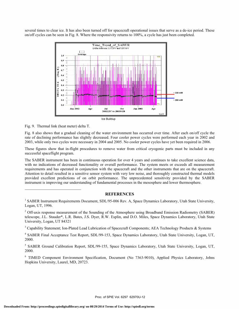
SABER has a calibrated thermal link between the FPA and the cryocooler that is used as a heat meter. The heat meter over the same period of time, January thru April 2003, showed a gradual increase in heat load. This was also backed up by increases in SABER cooler power consumed and a decrease of the operational heater power of the cryocooler. Fig. 9 shows the change in heat load experienced as the ice would build-up on the thermal link and the remainder of the FPA cooled structure. The heat increase was nearly 50 mW, which for the SABER FPA represents nearly a 30% change in the effective emissivity of the thermal blankets.
This data indicated that the cooler was working harder to compensate for the degraded blanket performance from the ice build-up. Once the problem was identified, it was determined that simply turning the cooler off for about 24 hours would dissipate all of the ice that formed on the blankets and FPA. When the SABER team turned off the coolers, the operation of instrument returned to its original performance. Over the course of the mission, the cooler has been turned on and off
Proc. of SPIE Vol. 6297 62970U-11
Downloaded From: http://proceedings.spiedigitallibrary.org/ on 08/29/2014 Terms of Use: http://spiedl.org/terms
0.9
0.8
0.7
0.6
0.5
0.4
0.3
0.2
0.1
0.0
*Time_Trend_of_SABERDelta between TFO3V and TFO6V
Jan 200220011207 to 20030420
Jan 2003
v2.O
several times to clear ice. It has also been turned off for spacecraft operational issues that serve as a de-ice period. These on/off cycles can be seen in Fig. 8. Where the responsivity returns to 100%, a cycle has just been completed.
Fig. 9. Thermal link (heat meter) delta T.
Fig. 8 also shows that a gradual cleaning of the water environment has occurred over time. After each on/off cycle the rate of declining performance has slightly decreased. Four cooler power cycles were performed each year in 2002 and 2003, while only two cycles were necessary in 2004 and 2005. No cooler power cycles have yet been required in 2006.
These figures show that in-flight procedures to remove water from critical cryogenic parts must be included in any successful spaceflight program.
The SABER instrument has been in continuous operation for over 4 years and continues to take excellent science data, with no indications of decreased functionality or overall performance. The system meets or exceeds all measurement requirements and has operated in conjunction with the spacecraft and the other instruments that are on the spacecraft. Attention to detail resulted in a sensitive sensor system with very low noise, and thoroughly constructed thermal models provided excellent predictions of on orbit performance. The unprecedented sensitivity provided by the SABER instrument is improving our understanding of fundamental processes in the mesosphere and lower thermosphere.
REFERENCES
1 SABER Instrument Requirements Document, SDL/95-006 Rev. A, Space Dynamics Laboratory, Utah State University, Logan, UT, 1996. 2 Off-axis response measurement of the Sounding of the Atmosphere using Broadband Emission Radiometry (SABER) telescope, J.L. Stauder*, L.R. Bates, J.S. Dyer, R.W. Esplin, and D.O. Miles, Space Dynamics Laboratory, Utah State University, Logan, UT 84321 3 Capability Statement; Ion-Plated Lead Lubrication of Spacecraft Components; AEA Technology Products & Systems 4 SABER Final Acceptance Test Report, SDL/99-153, Space Dynamics Laboratory, Utah State University, Logan, UT, 2000. 5 SABER Ground Calibration Report, SDL/99-155, Space Dynamics Laboratory, Utah State University, Logan, UT, 2000. 6 TIMED Component Environment Specification, Document (No 7363-9010), Applied Physics Laboratory, Johns Hopkins University, Laurel, MD, 20723.
~ 280 mW
~ 330 mW
Ice Buildup
Proc. of SPIE Vol. 6297 62970U-12
Downloaded From: http://proceedings.spiedigitallibrary.org/ on 08/29/2014 Terms of Use: http://spiedl.org/terms