SO/PHI The Solar Orbiter Polarimetric and Helioseismic Imager · The Solar Orbiter Polarimetric and...
40
J. Hirzberger – The SO/PHI Instrument, MPS-SGS October 28, 2014 SO/PHI The Solar Orbiter Polarimetric and Helioseismic Imager J. Hirzberger MPS Solar Group Seminar – October 28, 2014
Transcript of SO/PHI The Solar Orbiter Polarimetric and Helioseismic Imager · The Solar Orbiter Polarimetric and...
J. Hirzberger – The SO/PHI Instrument, MPS-SGS October 28, 2014
SO/PHI
The Solar Orbiter
Polarimetric and Helioseismic Imager J. Hirzberger
MPS Solar Group Seminar – October 28, 2014

J. Hirzberger – The SO/PHI Instrument, MPS-SGS October 28, 2014
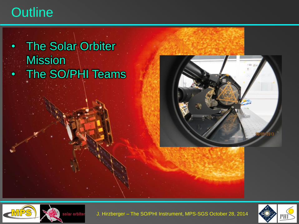
Outline
• The Solar Orbiter
Mission
J. Hirzberger – The SO/PHI Instrument, MPS-SGS October 28, 2014
Outline
• The Solar Orbiter
Mission
• The SO/PHI Teams

J. Hirzberger – The SO/PHI Instrument, MPS-SGS October 28, 2014
Outline
• The Solar Orbiter
Mission
• The SO/PHI Teams
• The SO/PHI Instrument
Principles
• The SO/PHI Instrument
Design
J. Hirzberger – The SO/PHI Instrument, MPS-SGS October 28, 2014
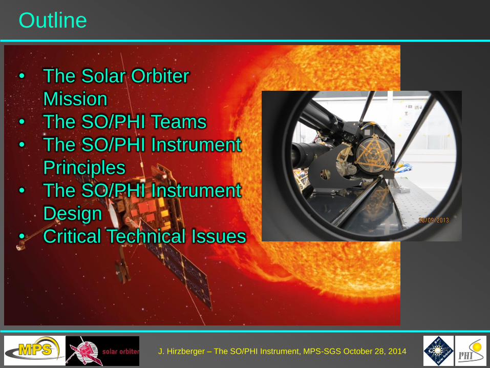
Outline
• The Solar Orbiter
Mission
• The SO/PHI Teams
• The SO/PHI Instrument
Principles
• The SO/PHI Instrument
Design
• Critical Technical Issues

J. Hirzberger – The SO/PHI Instrument, MPS-SGS October 28, 2014
Outline
• The Solar Orbiter
Mission
• The SO/PHI Teams
• The SO/PHI Instrument
Principles
• The SO/PHI Instrument
Design
• Critical Technical Issues
• Scientific Prospects
• Operational Issues

J. Hirzberger – The SO/PHI Instrument, MPS-SGS October 28, 2014
Outline
• The Solar Orbiter
Mission
• The SO/PHI Teams
• The SO/PHI Instrument
Principles
• The SO/PHI Instrument
Design
• Critical Technical Issues
• Scientific Prospects
• Operational Issues
• Conclusions
J. Hirzberger – The SO/PHI Instrument, MPS-SGS October 28, 2014
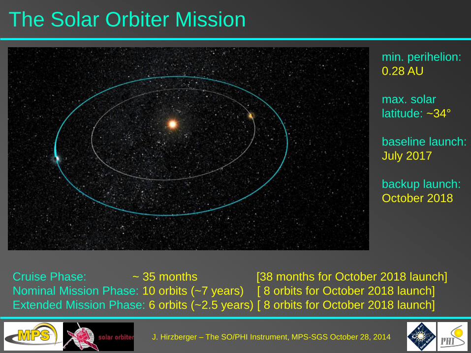
The Solar Orbiter Mission
min. perihelion:
0.28 AU
max. solar
latitude: ~34°
baseline launch:
July 2017
backup launch:
October 2018
Cruise Phase: ~ 35 months [38 months for October 2018 launch]
Nominal Mission Phase: 10 orbits (~7 years) [ 8 orbits for October 2018 launch]
Extended Mission Phase: 6 orbits (~2.5 years) [ 8 orbits for October 2018 launch]

J. Hirzberger – The SO/PHI Instrument, MPS-SGS October 28, 2014
The Solar Orbiter Spacecraft
Spacecraft:
Spacecraft bus with power supply (solar
panels) and telemetry system (retractable
high-gain antenna)
Heat shield (>9 solar constants per m2)
Instrument boom
Payload:
5 in-situ instruments
5 remote sensing instruments

J. Hirzberger – The SO/PHI Instrument, MPS-SGS October 28, 2014
The Solar Orbiter Payload
PHI
Optics
Unit
to be
updated!
J. Hirzberger – The SO/PHI Instrument, MPS-SGS October 28, 2014
The SO/PHI Science Team
PI: S.K. Solanki MPS
CoPI: J.C. del Toro Iniesta IAA, Granada
CoIs:
A. Gandorfer MPS
L. Gizon MPS
J. Hirzberger MPS
A. Lagg MPS
J. Schou MPS
U. Schühle MPS
W. Schmidt KIS, Freiburg
O. Von der Lühe KIS, Freiburg
H. Michalik IDA, Braunschweig
D. Orozco Suárez IAC, Tenerife
J. Blanco Rodríguez GACE, Valencia
V. Domingo Codoñer GACE, Valencia
L. Bellot Rubio IAA, Granada
A. Álvarez Herrero INTA, Madrid
I. Pérez Grande UPM, Madrid
J.M. Gómez Cama University Barcelona
T. Appourchaux IAS, Paris
P. Boumier IAS, Paris
T. Corbard OCA, Nice
G. Scharmer University Stockholm
M. Carlsson ITA, Oslo
W. Schmutz PMOD/WRC, Davos
P.S. Cally Monash University
P.H. Scherrer Stanford University
C.J. Schrijver LMSAL, Palo Alto
F. Hill NSO, Tucson
V. Martínez Pillet NSO, Boulder

J. Hirzberger – The SO/PHI Instrument, MPS-SGS October 28, 2014
The SO/PHI Consortium
Poject Office:
J. Woch MPS Project Manager (lead)
A. Gandorfer MPS Instrument Scientist
R. Meller MPS System Engineer/E
J. Staub MPS System Engineer/M
R. Müller MPS CPA
U. Beckmann MPS Configuration Control
W. Deutsch MPS AIV
S. Ramanath MPS Test Engineer
J. Hirzberger MPS Operations
T. Macke MPS Secretary
Sub-System Leads:
Mechanics: J. Staub MPS
Electronics: A. López Jiménez IAA, Granada
Thermal: I. Pérez Grande UPM, Madrid
Optics: A. Gandorfer MPS
Software: M. Kolleck MPS
Cleanliness: U. Schühle MPS
Filtergraph: T. Appourchaux IAS, Paris
Focal Plane Assembly: K. Heerlein MPS
Image Stabilization: R. Volkmer KIS, Freiburg
Full Disk Telescope, PMPs: A. Álvarez Herrero INTA, Madrid

J. Hirzberger – The SO/PHI Instrument, MPS-SGS October 28, 2014
The MPS SO/PHI Team
P. Bambach
U. Beckmann
M. Bergmann
J. Bischoff
J. Bochmann
W. Boogaerts
D. Busse
B. Chares
W. Deutsch
L. Duvall
R. Enge
A. Feller
G. Fernandez Rico
P. Ferreira
A. Gandorfer
D. Germerott
B. Grauf
L. Guerrero
K. Heerlein
J. Heinrichs
S. Herges
D. Hirche
J. Hirzberger
T. Keufner
M. Klaproth
C. Köhler
M. Kolleck
A. Lagg
T. Meierdierks
S. Meining
R. Meller
R. Mende
S. Meyer
M.F. Müller
R. Müller
D. Oberdorfer
I. Papagiannaki
S. Ramanath
T. Riethmüller
U. Schühle
S.K. Solanki
L. Song
M. Sperling
J. Staub
J. Utehs
S. Werner
J. Woch
A. Zerr
In addition:
A. Birch
L. Gizon
B. Löptien
J. Schou

J. Hirzberger – The SO/PHI Instrument, MPS-SGS October 28, 2014
SO/PHI Measurement Principle
PHI is a tunable imaging filtergraph:
Scans over a magnetic
sensitive photospheric
absorption line
(FeI 617.3nm)
Narrow-band
filtergrams at 6 spectral
positions
Full polarimetric
information
Fast image read-out
On-board data
processing
solar spectrum
PHI tunable passband
PHI order sorter

J. Hirzberger – The SO/PHI Instrument, MPS-SGS October 28, 2014
SO/PHI Primary Observables
-400 -160 -80 0 80 160 [mÅ]
I
U
Q
V
Full Stokes maps at 6 wavelength positions:
after onboard
data calibration
and polarimetric
demodulation !

J. Hirzberger – The SO/PHI Instrument, MPS-SGS October 28, 2014
PHI data products:
PHI requirements:
high-resolution data
full-disk data
2k x 2k FOV
1 data set per minute
SO/PHI Data Products
Dynamic
range
Noise
continuum intensity, Ic - ≤10-3
LOS velocity, vLOS ±5km/s ≤40m/s
LOS magnetic field strength, BLOS ±3.5kG 15 G
magnetic field inclination, γ 180° 1°
magnetic field azimuth, φ ±180° 2°

J. Hirzberger – The SO/PHI Instrument, MPS-SGS October 28, 2014
SO/PHI Field of Views
Two Telescopes:
Full Disk Telescope:
• FoV ~ 2°
• Resolution ~3.5 arcsec per pixel
• Full disk at all orbit positions
• 17 mm aperture diameter
High Resolution Telescope:
• FoV ~ 16 arcmin
• Resolution: 0.5 arcsec per pixel
• Resolution: ~200 km at closest
perihelion
• 140 mm aperture diameter
HRT FoV
FDT FoV

J. Hirzberger – The SO/PHI Instrument, MPS-SGS October 28, 2014
SO/PHI Functional Diagram (simplified)
4 Mechanisms
1 Active mirror
2x2 Tunable LCVRs
1 Tunable etalon 2 APS cameras 2 Entrance windows
2 Telescopes

J. Hirzberger – The SO/PHI Instrument, MPS-SGS October 28, 2014
SO/PHI Design – Optics Unit
• 2 AlBeMet main blocks
• 6 low CTE CFRP struts
• Al honeycomb baseplate
• Total volume: 30 x 40 x 80 cm
• Total mass: 35 kg
• HRT: off-axis Ritchey-Chrétien telescope
• FDT: off-axis refractor
• Polarization Packages: based on Liquid-
Crystal Variable Retarders (LCVRs)
• Filtergraph: transfer-optics with LiNbO3
solid state etalon and interference filters
• Image stabilization: 30 Hz Correlation Tracker
• Focal Plane: 2k / >10fps APS detector

J. Hirzberger – The SO/PHI Instrument, MPS-SGS October 28, 2014
SO/PHI Design – Electronics Unit
High Voltage Power Supply
Analog Motor and Heater Drivers
Tip-Tilt Controller & Memory Board
Digital Processing Unit
Power Converter Modules
(redundant & main)
PCM
top-view

J. Hirzberger – The SO/PHI Instrument, MPS-SGS October 28, 2014
New and Critical Technologies
• Line scanning: first ever solid-state etalon in space
• Polarization modulation: space-qualification of LCVRs for SO
• Science detector: custom made APS sensor development
• Heat rejection windows: optical/polarimetric performance between 0.28
and 0.9 AU
• Data processing:
- use of powerful reconfigurable FPGAs
- autonomous onboard calibration and data
processing
Most critical issue:
Low Telemetry: 6.4 GBytes perorbit≈100GBytes over entire mission
lifetime

J. Hirzberger – The SO/PHI Instrument, MPS-SGS October 28, 2014
Heat Rejection Entrance Windows
UV mirror
IR shield
617nm
hi-pass
617nm
lo-pass
Sun
PHI
space-side
temperature model
at perihelion
HRT-HREW
STM2

J. Hirzberger – The SO/PHI Instrument, MPS-SGS October 28, 2014
Filtergraph
Filtergraph
model
250μm
LiNbO3
etalon
• 2 optical windows (lenses, ITO coated)
• 2 interference filters (order sorter, IR blocker)
• 1 LiNbO3 etalon
• Oven (active thermal control)
• HV connection
Line scanning device based
on a solid state
Fabry-Pérot etalon
FWHM = 90mÅ
Free spectral range = 3.0Å
~ 1nm surface roughness
~10nm absolute thickness
tolerance
T-stability: <0.1K on etalon
66°C operating temperature
1.5 W heater power
J. Hirzberger – The SO/PHI Instrument, MPS-SGS October 28, 2014
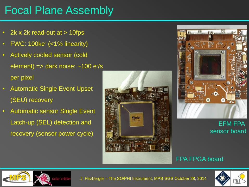
Focal Plane Assembly
• 2k x 2k read-out at > 10fps
• FWC: 100ke- (<1% linearity)
• Actively cooled sensor (cold
element) => dark noise: ~100 e-/s
per pixel
• Automatic Single Event Upset
(SEU) recovery
• Automatic sensor Single Event
Latch-up (SEL) detection and
recovery (sensor power cycle)
EFM FPA
sensor board
FPA FPGA board

J. Hirzberger – The SO/PHI Instrument, MPS-SGS October 28, 2014
Digital Processing Unit
Most critical items:
2 reconfigurable FPGAs for
onboard data analysis, image
acquisition and CT control
Tasks:
• Instrument control
• Science data Acquisition
with >10 fps
• Correlation Tracker control
• Onboard data calibration
• Onboard data inversion
• 4 Tbits flash memory
control
• Commanding/Telemetry

J. Hirzberger – The SO/PHI Instrument, MPS-SGS October 28, 2014
On-board Data Processing
27
FPA
Image
Accumulation
Pixel Binning
PSF
Deconvolution
Additional
Correction
Polarization
Demodulation
Cross-talk
Correction
Flat & Dark
Correction
Standard data pipeline
Optional processing steps
Additional paths (calibration, commissioning, etc.)
Data Pre-Processing:

J. Hirzberger – The SO/PHI Instrument, MPS-SGS October 28, 2014
On-board Data Processing (contd.)
28
S/C
RTE Bit truncation
Compression
Classical
Processing
4 Tbit
Flash memory
Telemetry
Packetting
Inversion and Compression:

J. Hirzberger – The SO/PHI Instrument, MPS-SGS October 28, 2014
Solar Orbiter Science Cases
How and where does the solar wind plasma and magnetic field originate in
the corona?
How do solar transients drive heliospheric variability?
How do solar eruptions produce energetic particle radiation that fills the
heliosphere?
How does the solar dynamo work and drive connections between the Sun
and the heliosphere?
Q1:
Q2:
Q3:
Q4:
J. Hirzberger – The SO/PHI Instrument, MPS-SGS October 28, 2014
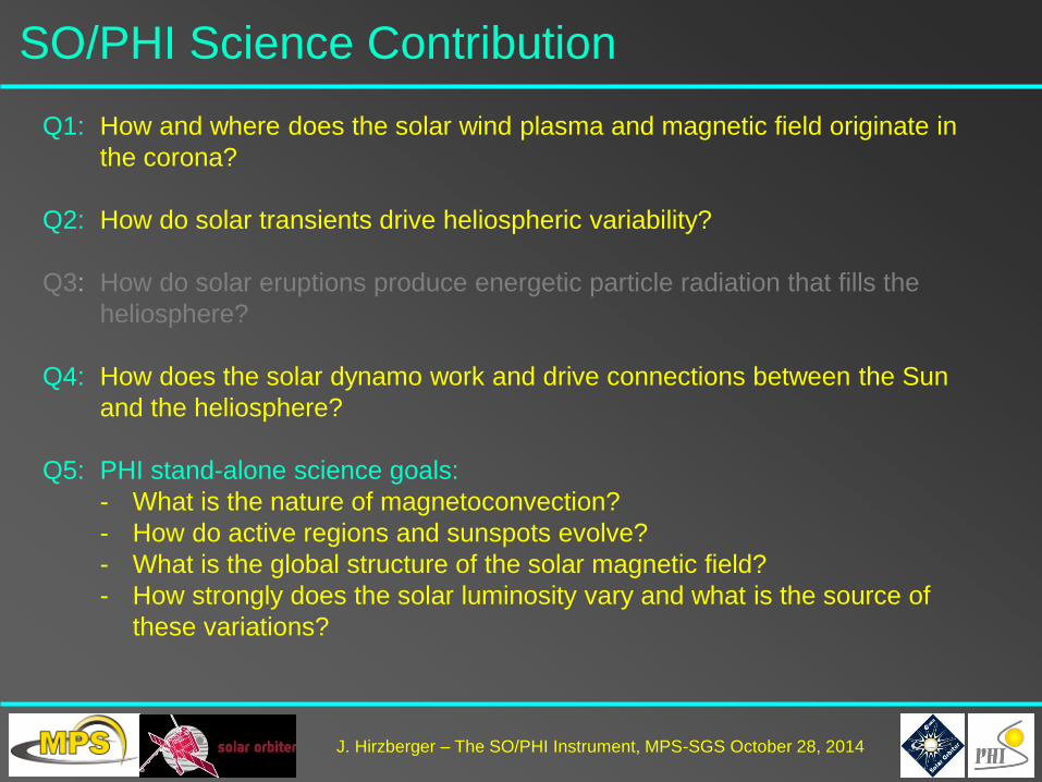
SO/PHI Science Contribution
How and where does the solar wind plasma and magnetic field originate in
the corona?
How do solar transients drive heliospheric variability?
How do solar eruptions produce energetic particle radiation that fills the
heliosphere?
How does the solar dynamo work and drive connections between the Sun
and the heliosphere?
PHI stand-alone science goals:
- What is the nature of magnetoconvection?
- How do active regions and sunspots evolve?
- What is the global structure of the solar magnetic field?
- How strongly does the solar luminosity vary and what is the source of
these variations?
Q1:
Q2:
Q3:
Q4:
Q5:

J. Hirzberger – The SO/PHI Instrument, MPS-SGS October 28, 2014
Atmospheric Coupling
SO is designed to probe all solar
layers from its interiour up to the
heliosphere. The most prominent
questions concern the magnetic
coupling between the different
atmospheric layers.
SO with both remote sensing and in-
situ measurements aims to address
the largely unsolved problems of
chromospheric and coronal heating
as well as the transport phenomena
into the interplanetary space
SO/PHI will provide the photospheric
magnetic field structure which
represents essential boundary
conditions to achieve these goals.
Marsch et al., 2004

J. Hirzberger – The SO/PHI Instrument, MPS-SGS October 28, 2014
Co-rotation and Global Sun Science
Tadesse et al., 2014
SO’scloseperiheliontransits
enables to follow surface
structures for more than half of a
rotation period, i.e. up to 23 days.
Vantage points far from Earth
allow for instantaneous 4π
magnetic maps
HMI synoptic map: 4.-17.9.2014
HMI movie: 4.-17.9.2014

J. Hirzberger – The SO/PHI Instrument, MPS-SGS October 28, 2014
Polar Science
Tsuneta et al., 2008
Polarimetric and dynamic studies of
the solar polar regions from the
ecliptic plane suffer from geometric
foreshortening. SO/PHI will be the
first polarimeter looking at the poles
from an inclination <83 deg.

J. Hirzberger – The SO/PHI Instrument, MPS-SGS October 28, 2014
Helioseismology with SO/PHI
Stereoscopic Helioseismology
Probing the Sun from different vantage points
may allow for probing deeper layers than what
is possible with only one instrument.
Observations from a vantage point in the ecliptic does
not allow probing solar latitudes higher than ~70°.
SO/PHI observations from out of the ecliptic will help to
accomplish the unsolved problems of, e.g., the solar
dynamo.

J. Hirzberger – The SO/PHI Instrument, MPS-SGS October 28, 2014
Science Phases
(NMP, EMP):
3 Remote Sensing
Windows (10 days
each) per orbit:
perihelion, min. and
max. latitude (tbd)
Cruise Phase:
2 instrument
check-outs per
year
NECP:
Instrument
commissioning
LEOP:
SO/PHI is off
Operations (I)

J. Hirzberger – The SO/PHI Instrument, MPS-SGS October 28, 2014
Operations (II)
High latitude RSW
Low latitude RSW
Perihelion RSW
Outside RSW SO/PHI will carry out onboard data analysis:
Raw data have to be kept in memory (4 Tbits internal memory size)
Post-facto data selection for an efficient use of limited Telemetry
Baseline concept, however, disallows long-term observations

J. Hirzberger – The SO/PHI Instrument, MPS-SGS October 28, 2014
SO/PHI Nominal Observations Mode
Telescope FDT HRT
Image size 2048 x 2048 2048 x 2048
Resolution 3.5”/pixel 0.5”/pixel
Cadence 60s 60 s
Parameters Ic,BLOS,γ, φ, vLOS Ic,BLOS,γ, φ, vLOS
Digital depths 10 bits (Ic,BLOS,vLOS), 8bits (γ, φ)
• Each data set requires 2048^2 x 46 = 184 Mbits
• Compression by a factor of 2 gives 92Mbits per
data set
Telemetry allocation allows only for ~500 data sets
per orbit!
In addition SO/PHI requires:
• Calibration data
• Raw data (sporadic)
• Overhead (file headers, housekeeping, etc.)

J. Hirzberger – The SO/PHI Instrument, MPS-SGS October 28, 2014
Science Prospects
Owing to the low telemetry and the baseline operation concept
(only 3 Remote Sensing Windows per orbit)
the achievement of the SO science goals will be highly insecure:
• Progress on the dynamo requires long-term/high-cadence
observations (feature tracking, helioseismology)
• Solar wind/heliospheric science requires long term synoptic
observations
The variable environment along the orbit will requires additional
effort and resources for instrument calibration, which will stress the
limited telemetry allocation:
• Re-calibration intervals will be short (at least prior to each RSW)
• Onboard data processing requires ground checks of calibration
results
• Sporadic downlink of raw data will secure smoothness onboard
data processing and will allow for advanced processing
procedures

J. Hirzberger – The SO/PHI Instrument, MPS-SGS October 28, 2014
SO/PHI Synoptic Mode - proposed
• Full-disk data sets:
- Continuum intensity
- Magnetic field vector
- Dopplergram (tbc)
• 1-4 data sets per day or longitude interval
• 1k x 1k maximum size (rebinning for d < 0.5 AU)
Magnetogram Continuum
intensity

J. Hirzberger – The SO/PHI Instrument, MPS-SGS October 28, 2014
SO/PHI Helioseismology - proposed
High-cadence (~1min)
Dopplergrams interlaced by
synoptic observations
Time series: 1 - 100 days (and
more) 80-90% duty cycle
Image sizes between 128 x128
and 2048 x 2048 pixels
Global (full-disk) and local (high-
resolution) helioseismology
observations intended
Most efficient data compression
strategy is under investigation
FDT HRT
Dopplergrams
(e.g. Löptien et al. 2014)

J. Hirzberger – The SO/PHI Instrument, MPS-SGS October 28, 2014
Conclusions
• SO/PHI is an extremely complex instrument on a highly ambitious space
mission.
• SO/PHI has incorporated a series of new technologies which have to be
functionally proven
• SO/PHI is an essential instrument to achieve the desired SO science goals -
the SO/PHI instrument concept and design allows for addressing a series of
the fundamental problems in solar physics.
• The current status of SO/PHI is solid, however, schedule issues have to be
tackled.
• The entire SO mission suffers from the extremely limited telemetry. SO/PHI is
one of the most telemetry starved instrument of the scientific payload. New
ideas to resolve these problems and to extract the potentials of the mission
concept are highly appreciated!