SOMO-14D - SparkFun Electronics€¦ · The SOMO-14D is a tiny Audio-Sound module that can play...
13
4D SYSTEMS SOMO-14D Embedded Audio-Sound Module Data Sheet Document Date: 24th November 2009 Document Revision: 3.0 © 2009 4D Systems www.4dsystems.com.au Page 1 of 13
Transcript of SOMO-14D - SparkFun Electronics€¦ · The SOMO-14D is a tiny Audio-Sound module that can play...
4D SYSTEMS
SOMO-14D Embedded Audio-Sound Module
Data Sheet
Document Date: 24th November 2009Document Revision: 3.0
© 2009 4D Systems www.4dsystems.com.au Page 1 of 13
4D SYSTEMS
SOMO-14DEmbedded Audio Module
Data Sheet
Description
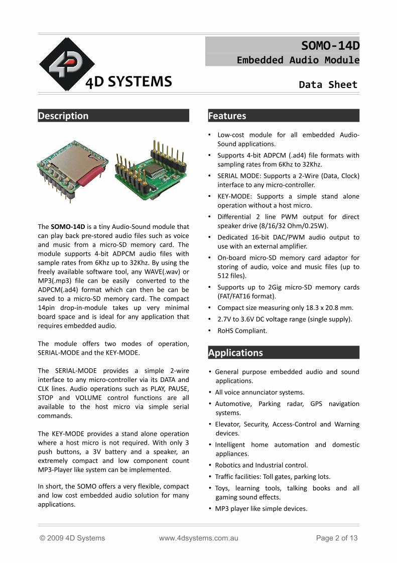
The SOMO-14D is a tiny Audio-Sound module that can play back pre-stored audio files such as voice and music from a micro-SD memory card. The module supports 4-bit ADPCM audio files with sample rates from 6Khz up to 32Khz. By using the freely available software tool, any WAVE(.wav) or MP3(.mp3) file can be easily converted to the ADPCM(.ad4) format which can then be can be saved to a micro-SD memory card. The compact 14pin drop-in-module takes up very minimal board space and is ideal for any application that requires embedded audio.
The module offers two modes of operation, SERIAL-MODE and the KEY-MODE.
The SERIAL-MODE provides a simple 2-wire interface to any micro-controller via its DATA and CLK lines. Audio operations such as PLAY, PAUSE, STOP and VOLUME control functions are all available to the host micro via simple serial commands.
The KEY-MODE provides a stand alone operation where a host micro is not required. With only 3 push buttons, a 3V battery and a speaker, an extremely compact and low component count MP3-Player like system can be implemented.
In short, the SOMO offers a very flexible, compact and low cost embedded audio solution for many applications.
Features
• Low-cost module for all embedded Audio-Sound applications.
• Supports 4-bit ADPCM (.ad4) file formats with sampling rates from 6Khz to 32Khz.
• SERIAL MODE: Supports a 2-Wire (Data, Clock) interface to any micro-controller.
• KEY-MODE: Supports a simple stand alone operation without a host micro.
• Differential 2 line PWM output for direct speaker drive (8/16/32 Ohm/0.25W).
• Dedicated 16-bit DAC/PWM audio output to use with an external amplifier.
• On-board micro-SD memory card adaptor for storing of audio, voice and music files (up to 512 files).
• Supports up to 2Gig micro-SD memory cards (FAT/FAT16 format).
• Compact size measuring only 18.3 x 20.8 mm.
• 2.7V to 3.6V DC voltage range (single supply).
• RoHS Compliant.
Applications
• General purpose embedded audio and sound applications.
• All voice annunciator systems.
• Automotive, Parking radar, GPS navigation systems.
• Elevator, Security, Access-Control and Warning devices.
• Intelligent home automation and domestic appliances.
• Robotics and Industrial control.
• Traffic facilities: Toll gates, parking lots.
• Toys, learning tools, talking books and all gaming sound effects.
• MP3 player like simple devices.
© 2009 4D Systems www.4dsystems.com.au Page 2 of 13
SOMO-14D Embedded Audio Module Data Sheet
Table of Contents
1. Pin Configuration and Summary................................................................................................42. Pin Description..............................................................................................................................5
2.1 Micro-controller Interface Pins ...............................................................................................5 CLK pin 3 (Serial Data Clock):.....................................................................................................5 DATA pin 4 (Serial Data In):........................................................................................................5
2.2 Key Interface Pins ....................................................................................................................5 NEXT pin 1:................................................................................................................................5 PLAY/STOP pin 6:.......................................................................................................................5 PREVIOUS pin 7:........................................................................................................................5
2.3 Audio Output Pins ...................................................................................................................5 SPK+, SPK- pins 11, 12:..............................................................................................................5 AUDIO pin 14:............................................................................................................................5 BUSY pin 5:................................................................................................................................5
2.4 System Pins...............................................................................................................................6 RESET pin 10 (Module Master Reset):.......................................................................................6 GND pin 9 (Module Ground):....................................................................................................6 VCC pin 8 (Module Supply Voltage Input):................................................................................6
3. Operating Modes..........................................................................................................................63.1 SERIAL MODE ...........................................................................................................................6
Command Codes:......................................................................................................................63.2 KEY MODE ................................................................................................................................7
4. microSD Cards – FAT16 Format..................................................................................................75. Mechanical Dimensions..............................................................................................................86. Development and Support Tools...............................................................................................8
6.1 OLED Display Modules..............................................................................................................86.2 Development Boards................................................................................................................96.3 SOMO Audio Converter – Software Tool..................................................................................9
7. Timing Diagrams.........................................................................................................................107.1 Serial Data Timing and Waveform..........................................................................................10
8. Specifications and Ratings........................................................................................................11Proprietary Information.................................................................................................................12Disclaimer of Warranties & Limitation of Liability.....................................................................12Contact Information........................................................................................................................12Revision History...............................................................................................................................13
© 2009 4D Systems www.4dsystems.com.au Page 3 of 13
SOMO-14D Embedded Audio Module Data Sheet
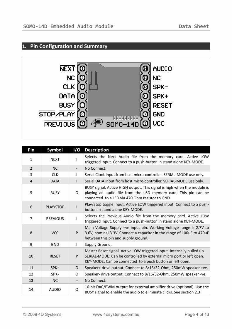
1. Pin Configuration and Summary
Pin Symbol I/O Description
1 NEXT ISelects the Next Audio file from the memory card. Active LOW triggered input. Connect to a push-button in stand alone KEY-MODE.
2 NC - No Connect.
3 CLK I Serial Clock input from host micro-controller. SERIAL-MODE use only.
4 DATA I Serial DATA input from host micro-controller. SERIAL-MODE use only.
5 BUSY OBUSY signal. Active HIGH output. This signal is high when the module is playing an audio file from the uSD memory card. This pin can be connected to a LED via 470 Ohm resistor to GND.
6 PLAY/STOP IPlay/Stop toggle input. Active LOW triggered input. Connect to a push-button in stand alone KEY-MODE.
7 PREVIOUS ISelects the Previous Audio file from the memory card. Active LOW triggered input. Connect to a push-button in stand alone KEY-MODE.
8 VCC PMain Voltage Supply +ve input pin. Working Voltage range is 2.7V to 3.6V, nominal 3.3V. Connect a capacitor in the range of 100uF to 470uF between this pin and supply ground.
9 GND I Supply Ground.
10 RESET PMaster Reset signal. Active LOW triggered input. Internally pulled up. SERIAL-MODE: Can be controlled by external micro port or left open.KEY-MODE: Can be connected to a push button or left open.
11 SPK+ O Speaker+ drive output. Connect to 8/16/32-Ohm, 250mW speaker +ve.
12 SPK- O Speaker- drive output. Connect to 8/16/32-Ohm, 250mW speaker -ve.
13 NC -- No Connect.
14 AUDIO O16-bit DAC/PWM output for external amplifier drive (optional). Use the BUSY signal to enable the audio to eliminate clicks. See section 2.3
© 2009 4D Systems www.4dsystems.com.au Page 4 of 13
SOMO-14D Embedded Audio Module Data Sheet
2. Pin Description
This section describes in detail the hardware interface pins of the SOMO (SOund MOdule).
2.1 Micro-controller Interface Pins
CLK pin 3 (Serial Data Clock):Synchronous Clock Input. Each serial data bit is latched into the module on the rising edge of the clock. The idle state of the clock must be high. When communication is required, the CLK is brought LOW for a period of 2ms (START bit wait time). Each individual data bit (starting with the MSB bit15) is then clocked in sequentially. The data is latched on every rising edge of the clock. When the last data bit (bit0) is clocked in the CLK signal must be held high for a period of 2ms (STOP bit wait time) before the next command data is sent. The clock HIGH and LOW periods are 100us minimum.Refer to “Section 7. Timing Diagrams“ for more detailed timing and waveform information.
DATA pin 4 (Serial Data In):Synchronous Data Input. The data is presented to the module by the host micro via this pin. Each command data is 16 bits wide. Data is serially clocked in to the module starting with the most significant bit (MSB bit15). Refer to “Section 7. Timing Diagrams“ for more detailed timing and waveform information.
NOTE: For 5V systems, connect a series resistor (100 to 470 Ohms range) on the CLK and DATA pins between the SOMO and the target micro-controller.
2.2 Key Interface Pins
NEXT pin 1:Selects the Next Audio file from the micro-SD memory card. Active LOW triggered input. Connect this pin to a push-button in stand alone KEY-MODE.
PLAY/STOP pin 6:Play/Stop active LOW trigger Input. Connect this pin to a push-button in stand alone KEY-MODE. Each active low trigger will alternate between PLAY and STOP operation.
PREVIOUS pin 7:Selects the Previous Audio file from the micro-SD memory card. Active LOW triggered input. Connect this pin to a push-button in stand alone KEY-MODE.
2.3 Audio Output and Control Pins
SPK+, SPK- pins 11, 12:These pins provide a differential PWM+ and PWM- output to a speaker. Connect these pins to an 8/16/32 Ohm (250mW) speaker.
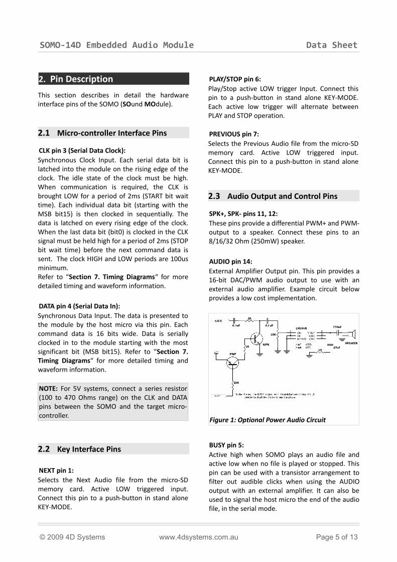
AUDIO pin 14:External Amplifier Output pin. This pin provides a 16-bit DAC/PWM audio output to use with an external audio amplifier. Example circuit below provides a low cost implementation.
BUSY pin 5:Active high when SOMO plays an audio file and active low when no file is played or stopped. This pin can be used with a transistor arrangement to filter out audible clicks when using the AUDIO output with an external amplifier. It can also be used to signal the host micro the end of the audio file, in the serial mode.
© 2009 4D Systems www.4dsystems.com.au Page 5 of 13
Figure 1: Optional Power Audio Circuit
SOMO-14D Embedded Audio Module Data Sheet
2.4 System Pins
RESET pin 10 (Module Master Reset):Module Master Reset pin. Active LOW input. Internally pulled up. After 1 second of a reset, the module will go into low power standby mode (8.0uA) if it detects no activity.
GND pin 9 (Module Ground):Module ground pin. This pin must be connected to ground.
VCC pin 8 (Module Supply Voltage Input):Module supply voltage input pin. This pin must be connected to a regulated supply voltage in the range of 2.7 to 3.6 Volts DC. Nominal operating voltage is 3.3 Volts. Connect a capacitor in the range of 100uF to 470uF between this pin and supply ground. Figure 2 shows several power supply options.
3. Operating Modes
The SOMO module offers two modes of operation, SERIAL-MODE and the KEY-MODE. This section describes both modes in detail.
3.1 SERIAL MODE
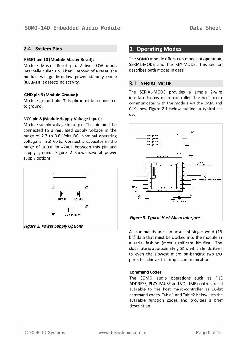
The SERIAL-MODE provides a simple 2-wire interface to any micro-controller. The host micro communicates with the module via the DATA and CLK lines. Figure 2.1 below outlines a typical set up.
All commands are composed of single word (16 bit) data that must be clocked into the module in a serial fashion (most significant bit first). The clock rate is approximately 5Khz which lends itself to even the slowest micro bit-banging two I/O ports to achieve this simple communication.
Command Codes:The SOMO audio operations such as FILE ADDRESS, PLAY, PAUSE and VOLUME control are all available to the host micro-controller as 16-bit command codes. Table1 and Table2 below lists the available function codes and provides a brief description.
© 2009 4D Systems www.4dsystems.com.au Page 6 of 13
Figure 3: Typical Host Micro Interface
Figure 2: Power Supply Options
SOMO-14D Embedded Audio Module Data Sheet
COMMAND CODE FUNCTION DESCRIPTION
0000h – 01FFh AUDIO FILE ADDRESSSelects one of the pre-stored audio/sound/voice files in the microSD memory card (up to 512 files max).
FFF0h – FFF7h VOLUMEVolume adjustment codes. Total of 8 levels. FFF0h is the minimum and FFF7 is the maximum (also the default) volume level. The volume can be adjusted during play or standby state.
FFFEh PLAY/PAUSE Plays or Pauses the current audio file.
FFFFh STOPStops playing the current audio file and puts the module in the ow power idle mode.
Table 1: Command Code Description
COMMAND CODE FILE ADDRESS FILE NAME
0000h (0000dec) File Address 1 “0000.ad4”
0001h (0001dec) File Address 2 “0001.ad4”
0002h (0002dec) File Address 3 “0002.ad4”
.. .. ..
01FFh (0511dec) File Address 512 “0511.ad4”
Note1: The file names stored in the microSD card must be the ASCII representation of the decimal command code with .ad4 extension:“0000.ad4”, “0001.ad4”, …, “0511.ad4”
Note2: It is recommended that the uSD card be reformatted when new audio files are stored.
Table 2: Audio File Addresses
3.2 KEY MODE
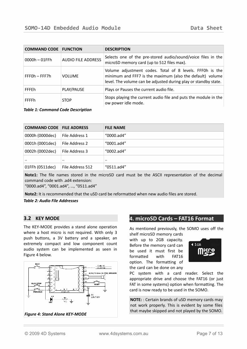
The KEY-MODE provides a stand alone operation where a host micro is not required. With only 3 push buttons, a 3V battery and a speaker, an extremely compact and low component count audio system can be implemented as seen in Figure 4 below.
4. microSD Cards – FAT16 Format
As mentioned previously, the SOMO uses off the shelf microSD memory cards with up to 2GB capacity. Before the memory card can be used it must first be formatted with FAT16 option. The formatting of the card can be done on any PC system with a card reader. Select the appropriate drive and choose the FAT16 (or just FAT in some systems) option when formatting. The card is now ready to be used in the SOMO.
NOTE: : Certain brands of uSD memory cards may not work properly. This is evident by some files that maybe skipped and not played by the SOMO.
© 2009 4D Systems www.4dsystems.com.au Page 7 of 13
Figure 4: Stand Alone KEY-MODE
SOMO-14D Embedded Audio Module Data Sheet
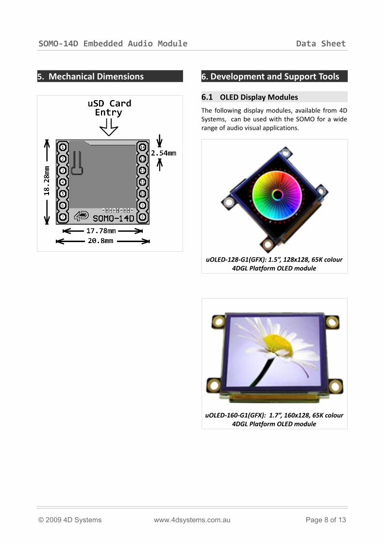
5. Mechanical Dimensions 6. Development and Support Tools
6.1 OLED Display Modules
The following display modules, available from 4D Systems, can be used with the SOMO for a wide range of audio visual applications.
© 2009 4D Systems www.4dsystems.com.au Page 8 of 13
uOLED-160-G1(GFX): 1.7”, 160x128, 65K colour 4DGL Platform OLED module
uOLED-128-G1(GFX): 1.5”, 128x128, 65K colour 4DGL Platform OLED module
SOMO-14D Embedded Audio Module Data Sheet
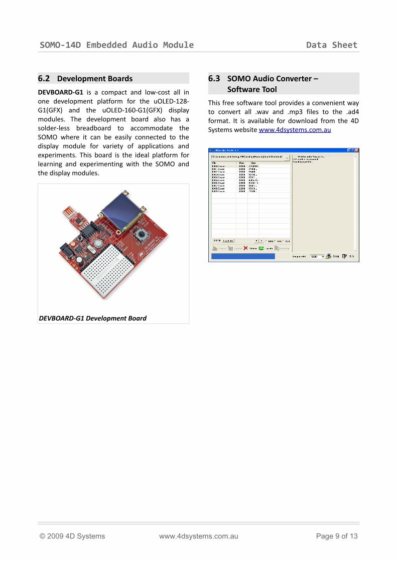
6.2 Development Boards
DEVBOARD-G1 is a compact and low-cost all in one development platform for the uOLED-128-G1(GFX) and the uOLED-160-G1(GFX) display modules. The development board also has a solder-less breadboard to accommodate the SOMO where it can be easily connected to the display module for variety of applications and experiments. This board is the ideal platform for learning and experimenting with the SOMO and the display modules.
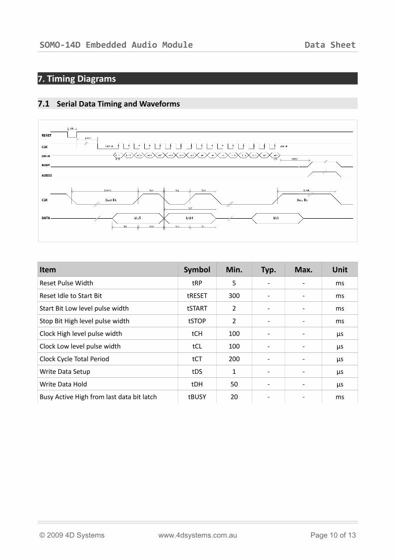
6.3 SOMO Audio Converter – Software Tool
This free software tool provides a convenient way to convert all .wav and .mp3 files to the .ad4 format. It is available for download from the 4D Systems website www.4dsystems.com.au
© 2009 4D Systems www.4dsystems.com.au Page 9 of 13
DEVBOARD-G1 Development Board
SOMO-14D Embedded Audio Module Data Sheet
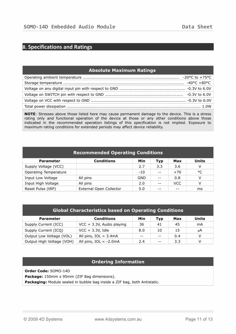
7. Timing Diagrams
7.1 Serial Data Timing and Waveforms
Item Symbol Min. Typ. Max. Unit
Reset Pulse Width tRP 5 - - ms
Reset Idle to Start Bit tRESET 300 - - ms
Start Bit Low level pulse width tSTART 2 - - ms
Stop Bit High level pulse width tSTOP 2 - - ms
Clock High level pulse width tCH 100 - - µs
Clock Low level pulse width tCL 100 - - µs
Clock Cycle Total Period tCT 200 - - µs
Write Data Setup tDS 1 - - µs
Write Data Hold tDH 50 - - µs
Busy Active High from last data bit latch tBUSY 20 - - ms
© 2009 4D Systems www.4dsystems.com.au Page 10 of 13
SOMO-14D Embedded Audio Module Data Sheet
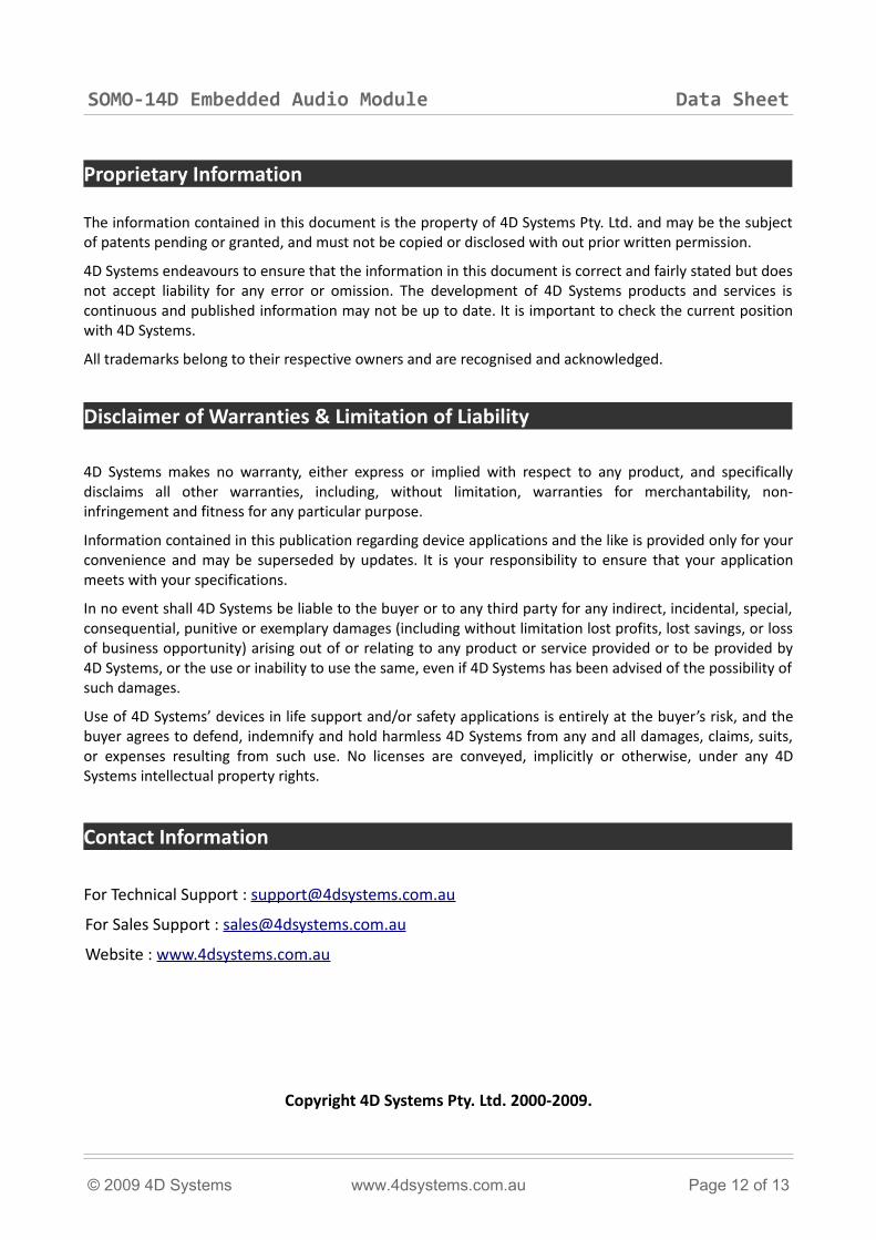
8. Specifications and Ratings
Absolute Maximum Ratings
Operating ambient temperature .......................................................................... -20°C to +75°C
Storage temperature ............................................................................................. -40°C +80°C
Voltage on any digital input pin with respect to GND ................................................... -0.3V to 6.0V
Voltage on SWITCH pin with respect to GND ............................................................ -0.3V to 6.0V
Voltage on VCC with respect to GND ......................................................................... -0.3V to 6.0V
Total power dissipation ....................................................................................................... 1.0W
NOTE: Stresses above those listed here may cause permanent damage to the device. This is a stress rating only and functional operation of the device at those or any other conditions above those indicated in the recommended operation listings of this specification is not implied. Exposure to maximum rating conditions for extended periods may affect device reliability.
Recommended Operating Conditions
Parameter Conditions Min Typ Max Units
Supply Voltage (VCC) 2.7 3.3 3.6 V
Operating Temperature -10 -- +70 °C
Input Low Voltage All pins GND -- 0.8 V
Input High Voltage All pins 2.0 -- VCC V
Reset Pulse (tRP) External Open Collector 5.0 -- -- ms
Global Characteristics based on Operating Conditions
Parameter Conditions Min Typ Max Units
Supply Current (ICC) VCC = 3.3V, Audio playing 36 41 45 mA
Supply Current (ICQ) VCC = 3.3V, Idle 8.0 10 15 µA
Output Low Voltage (VOL) All pins, IOL = 3.4mA -- -- 0.4 V
Output High Voltage (VOH) All pins, IOL = -2.0mA 2.4 -- 3.3 V
Ordering Information
Order Code: SOMO-14D
Package: 150mm x 95mm (ZIF Bag dimensions).
Packaging: Module sealed in bubble bag inside a ZIF bag, both Antistatic.
© 2009 4D Systems www.4dsystems.com.au Page 11 of 13
SOMO-14D Embedded Audio Module Data Sheet
Proprietary Information
The information contained in this document is the property of 4D Systems Pty. Ltd. and may be the subject of patents pending or granted, and must not be copied or disclosed with out prior written permission.
4D Systems endeavours to ensure that the information in this document is correct and fairly stated but does not accept liability for any error or omission. The development of 4D Systems products and services is continuous and published information may not be up to date. It is important to check the current position with 4D Systems.
All trademarks belong to their respective owners and are recognised and acknowledged.
Disclaimer of Warranties & Limitation of Liability
4D Systems makes no warranty, either express or implied with respect to any product, and specifically disclaims all other warranties, including, without limitation, warranties for merchantability, non-infringement and fitness for any particular purpose.
Information contained in this publication regarding device applications and the like is provided only for your convenience and may be superseded by updates. It is your responsibility to ensure that your application meets with your specifications.
In no event shall 4D Systems be liable to the buyer or to any third party for any indirect, incidental, special, consequential, punitive or exemplary damages (including without limitation lost profits, lost savings, or loss of business opportunity) arising out of or relating to any product or service provided or to be provided by 4D Systems, or the use or inability to use the same, even if 4D Systems has been advised of the possibility of such damages.
Use of 4D Systems’ devices in life support and/or safety applications is entirely at the buyer’s risk, and the buyer agrees to defend, indemnify and hold harmless 4D Systems from any and all damages, claims, suits, or expenses resulting from such use. No licenses are conveyed, implicitly or otherwise, under any 4D Systems intellectual property rights.
Contact Information
For Technical Support : [email protected]
For Sales Support : [email protected]
Website : www.4dsystems.com.au
Copyright 4D Systems Pty. Ltd. 2000-2009.
© 2009 4D Systems www.4dsystems.com.au Page 12 of 13
SOMO-14D Embedded Audio Module Data Sheet
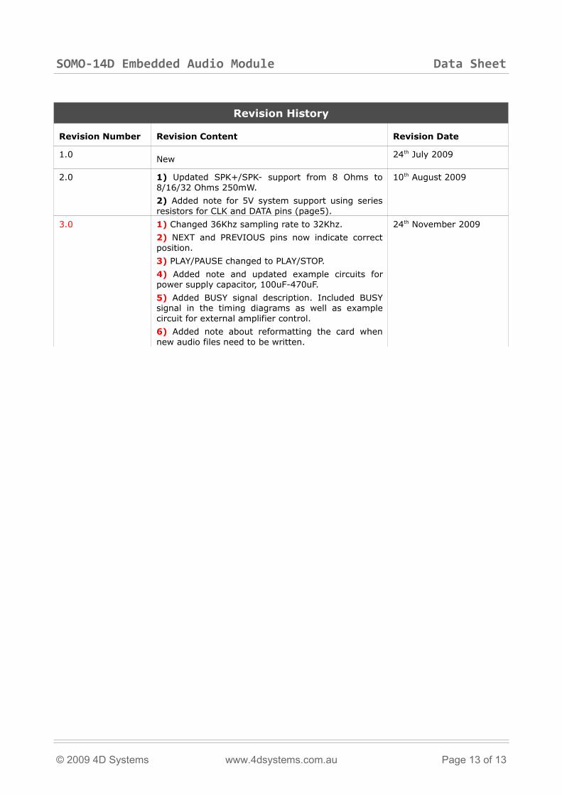
Revision History
Revision Number Revision Content Revision Date
1.0 New 24th July 2009
2.0 1) Updated SPK+/SPK- support from 8 Ohms to 8/16/32 Ohms 250mW.
2) Added note for 5V system support using series resistors for CLK and DATA pins (page5).
10th August 2009
3.0 1) Changed 36Khz sampling rate to 32Khz.
2) NEXT and PREVIOUS pins now indicate correct position.
3) PLAY/PAUSE changed to PLAY/STOP.
4) Added note and updated example circuits for power supply capacitor, 100uF-470uF.
5) Added BUSY signal description. Included BUSY signal in the timing diagrams as well as example circuit for external amplifier control.
6) Added note about reformatting the card when new audio files need to be written.
24th November 2009
© 2009 4D Systems www.4dsystems.com.au Page 13 of 13