SOME CHARACTERISTICS OF THE …arizona.openrepository.com/arizona/bitstream/10150/...SOME...
25
Some Characteristics of the International Space Channel Item Type text; Proceedings Authors Noack, T. L.; Poland, W. B., Jr. Publisher International Foundation for Telemetering Journal International Telemetering Conference Proceedings Rights Copyright © International Foundation for Telemetering Download date 06/06/2018 14:37:36 Link to Item http://hdl.handle.net/10150/609297
Transcript of SOME CHARACTERISTICS OF THE …arizona.openrepository.com/arizona/bitstream/10150/...SOME...

Some Characteristics of the International Space Channel
Item Type text; Proceedings
Authors Noack, T. L.; Poland, W. B., Jr.
Publisher International Foundation for Telemetering
Journal International Telemetering Conference Proceedings
Rights Copyright © International Foundation for Telemetering
Download date 06/06/2018 14:37:36
Link to Item http://hdl.handle.net/10150/609297

SOME CHARACTERISTICS OF THE INTERNATIONALSPACE CHANNEL
T.L. NoackDepartment of EE
University of Missouri-Rolla
W.B. Poland, Jr.NASA
Goddard Space Flight Center
Summary. Some physical characteristics of radio transmission links and the technologyof PCM modulation combine with the Radio Regulations of the InternationalTelecommunications Union to define a communications channel having a determinablechannel capacity, error rate, and sensitivity to interference. These characteristics and thecorresponding limitations on EIRP, power flux density, and power spectral density forspace service applications are described. The ITU regulations create a critical height of1027 km where some parameters of the limitation rules change. The nature of restraints onpower spectral density are discussed and an approach to a standardized representation ofNecessary Bandwidth for the Space Services is described. It is shown that, given the PFD(power flux density) and PSD (power spectral density) limitations of radio regulations, thechannel performance is determined by the ratio of effective receiving antenna aperture tosystem noise temperature. Based on this approach, the method for a quantitative trade-offbetween spectrum spreading and system performance is presented. Finally, the effects ofradio frequency interference between standard systems is analyzed.
Introduction. The increased crowding of the radio spectrum has placed a premium onmeasures to ensure compatibility among users of telecommunication channels, bothnational and international. Because of a spacecraft’s mobility the international aspects ofspectrum management are particularly important in space applications. The RadioRegulations of the International Telecommunications Union (referred to as RR) combinewith the physical characteristics of radio links to form a basis for preventing harmfulinterference among users. Although these regulations were formulated at or before the lastWorld Administrative Radio Conference (WARC) in 1970, and constitute an internationaltreaty obligation to which the United States and many other nations are committed, theredoes not appear to be a concise available source of information which describes the basiccharacteristics of the space radio channel for a data system designer. This paper presentssome of the more important channel characteristics with respect to power flux density,

power spectral density, geometry, interference protection, and channel capacity. We do notconsider any propagation effects.
A glossary of key terms and definitions of parameters is included at the end of the text.Some definitions of terms appear in Appendix A.
In developing a general method for spectrum representation, the user may be confronted bya dilemma: the spectra encountered may be either continuous or discrete, or a combinationof the two. Continuous spectra are ordinarily presented by their power spectral density(PSD) functions, but the PSD for a discrete spectrum has lines of infinite height and zerowidth, which are not measurable by real equipment. As a compromise, the radioregulations adopt a finite “reference resolution bandwidth” (RRB)which is determined bythe requirements of established services for a given band. In almost all bands, the RRB iseither 4 kHz, 1 MHz, or 1.5 MHz. When measurements are made using equipment havingother resolution bandwidths, a simple scaling of the results is usually made, based on anassumption of uniform spectral distribution of noise and signal (except for signals havingline spectra). Taking the 3-dB resolution bandwidth of the spectrum measuring device hasbeen found to be satisfactory in most cases. The resulting spectrum curves for a givensignal may differ somewhat from those appearing in text books for theoretical (infiniteresolution) spectra but they provide standard finite quantitative and measurable values forboth discrete and continuous specra. In general, the use of a finite resolution bandwidthhas negligible effect on the spectrum displayed if the resolution bandwidth is small incomparison to the features of interest in the spectrum.
A standardized representation of radio frequency emission is also aided by reference topower flux density (PFD). This quantity is invariably expressed in terms of dB with respectto one watt of power passing through a one square meter area normal to the direction ofpropagation in a spectral band equal to a reference resultion bandwidth; e.g., dB
POWER FLUX DENSITY. The severest limitations on communications are imposedby the regulations limiting power flux density from space at the earth’s surface. Themaximum values of PFD permitted for transmitters operated by the Federal Governmentare indicated in Appendix B.
Relevant geometry is indicated in Figure 1 and a representation of the limitations on powerflux density is shown in Figure 2. Although the maximum absolute level of power fluxdensity which is permitted depends on the frequency band, the limitations on power fluxdensity follow the same pattern in all bands. If one assumes either that a spacecraft emitsisotropically or that the spacecraft rotates in such a way as to assume a variety of attitudes,

Figure 2 shows that the PFD at the subsatellite point controls permissible EIRP of aspacecraft for heights up to 1027 km (638 miles); at greater heights the spacecraft EIRP iscontrolled by the power flux density received at the earth’s surface at points where thespacecraft appears at 5E elevation angle. At 1027 km height the difference in the RRlimitations on power flux density at 5E and 90E elevation are just compensated by thedifference in slant range for 5E elevation (point A of Figure 2) and 90E elevation (point Bof Figure 2). The maximum permitted EIRP corresponding to these limitations is depictedin Figure 3. Figure 4 shows the maximum value of PFD at various elevation angles for aspacecraft emitting at the EIRP indicated in Figure 3.
For earth stations in the space service, the radio regulations are primarily aimed at limitingthe power flux density at nearby stations on the surface of the earth and near geostationaryspacecraft. Figures 5, 6, and 7 indicate the nature of these limitations.
With a few exceptions the limitations on power flux density for transmissions from spaceto earth apply only in space bands above 1 GHz.
POWER SPECTRAL DENSITY. The power flux density limitation described aboveapplies to any reference resolution bandwidth in the emission spectrum of a transmitter inthe space services. An additional set of requirements is placed on the shape of an emittedspectrum.
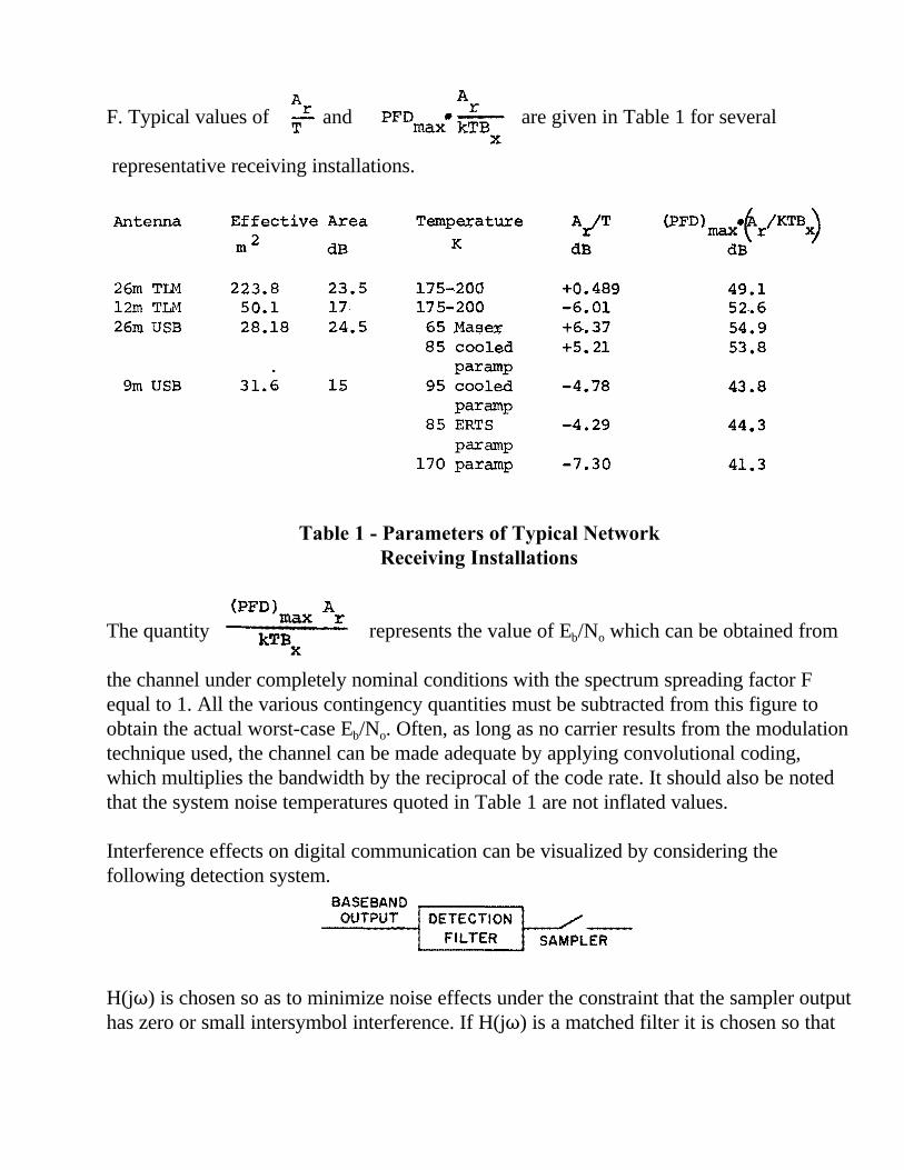
Most spacecraft telemetry or command spectra consist of a PCM baseband impressed onan FSK, PM, or PSK carrier or subcarrier. Definitions of various PCM waveforms arecontained in Figure 8. Two PCM spectra resulting from a random bit stream are shown inFigure 9a and 9b. A spectrum analyzer having a finite resolution bandwidth will distort thetheoretical spectrum of Figure 9. For example, a baseband PCM spectrum measured by aspactrum analyzer having a resolution bandwidth equal to one-half the PCM bit rate showsa pattern of nodes decreased about 1 dB from the theoretical spectrum but the nulls havealmost disappeared (see Figure 10a and 10b). As the relative size of the resolutionbandwidth increases in comparison to bit rate, the spectrum becomes more and moredistorted, until in the end it approximates the resolution element rather than the signalspectrum. Since the nodes determine the EIRP of a transmitter and the envelope of thespectrum, the theoretical spectrum for a PCM transmission using AM, PSK, or PM can beused to predict within about 1 dB the significant characteristics of an emission forpurposes of determining conformance to the radio regulations provided the RRB is nogreater than one half of the PCM bit rate.
With some forms of modulation, for example AM or PM, a portion of the total power iscommonly left in the carrier. This results in a spectral line of constant amplitude at thecarrier frequency. If the sideband power is spread widely over the spectrum, as is the case

when the PCM bit rate is high, the power in the RRB containing this spectral line mayexceed the power in an RRB for the sidebands. For example, with a 4 kHz and 20 per centcarrier power (the standard amount for telemetry signals received by NASA STDN), themeasured PSD for the carrier line will equal the peak measured PSD for the sidebands at abit rate of about 16 kb/s for PCM NRZ and about 8 kb/s for PCM Bi-0/ . At bit rates abovethese values, PSK or some other carrier-free modulation technique should be considered inorder to operate efficiently under the RR limitations for PFD.
The spectra shown in Figures 10a and 10b are those that would be generated withoutfiltering. Ordinarily the power contained in a PCM spectrum beyond the first null isconsidered negligible for purposes of signal detection; however, the skirts of the spectrumare important because of their potential ability to cause interference. For a variety of signaltypes using AM or PM carrier modulation, the spectrum rolls off at 6 dB/octave. It hasbeen found practicable to impose on system designers an additional requirement forfiltering the transmitted signal so as to attenuate the spectral skirts with a 12 dB/octaveslope, giving a net asymptotic slope of the spectral envelope of 18 dB/octave. UnfilteredFM modulation spectra tend to remain flatter in the center and roll off more rapidly at theedges than AM or PM spectra. An FM spectrum with high modulation index approximatesthe amplitude distribution of the modulating signal.
In determining the required system characteristics for a given mission, the designer mustconsider the worst case bit error rate that can be tolerated. From this, the value of Eb/No
energy per bit divided noise power density) can be chosen. In the PSD plots (Figures 9 and10) it turns out that the ordinate actually represents Eb; i.e., the highest point on the PCM-NRZ curve shown in Figure 9a represents the energy per bit for that signal. The requiredvalue of Eb/No, that is, the required dynamic range for a given signal, can therefore berepresented by marking off an appropriate number of dB down from the peak of the PSDspectrum. This required dynamic range is then an important parameter in specifying therealistic requirement of a signal for freedom from interference by noise or other signals.
LIMITATIONS ON POWER SPECTRAL DENSITY. In order to implement sharingof the radio spectrum without harmful intereference, the international radio regulations andthe corresponding U. S. regulations have employed restrictions on the spectral distributionof transmitter power. These restrictions usually take the form of a set of maximum levelswhich may be used at various frequency displacement from the assigned frequency. On aspectral plot this results in a spectral profile resembling a descending staircase. Foremissions supported by the NASA STDN Network, a somewhat different approach hasbeen used (see Figure 11). This profile usually permits the actual transmitted spectrum tobe fitted quite closely to the spectral limitation using a degree of filtering which in practicehas proved to be about the maximum that can be feasibily imposed on operatingspacecraft. The initial 10 dB step permits a closer fit of the profile to an FM spectrum

which tends to drop off more sharply than PM or AM. Current plans of the GSFCstandards group are to apply this spectral criterion to the power flux density of the signal inthe neighborhood of the receiver.
When required dynamic range is combined with the profile of Figure 11, a standardizedmeans of determining the bandwidth actually required for a transmission, the so-called“Necessary Bandwidth,” is obtained. The profile of Figure 11 and the required dynamicrange then define a standardized region which must be kept free of interference. Such anapproach has been proposed for adoption as an OTP standard for Government spaceapplications.
VARIATIONS The PFD at the earth’s surface resulting from emissions from aspacecraft transmitter may vary substantially, although the variations are no greater thanthose experienced in other services. For low earth orbiters (e.g., h = 161 km [100 miles])slant range at 5E elevation from a receiving station is about 989 km (615 statute miles) andat 15E elevation, it is about 541 km (336 statute miles). These slant ranges produce PFDvariation from an isotropic emitter of 15.8 dB and 10.5 dB respectively. Elevations of 5Eor more are usually a necessity for good reception, and 15E is strongly preferred. Atsynchronous distance, the path-length attenuation exceeds that for h = 161 km at zenith byabout 45 dB, and at lunar distance the change in path-length attenuation is about 68 dB.
A so-called omni-directional antenna (isotropic emitter) is often defined as one whichmaintains gain within +3 dB to -6 dB over 98% of the 4 B steradian solid angle. If the PFDlimit specified in the radio regulations is taken as the strict upper limit, the system usermust contend with actual PFD’s on the order of 9 dB below this maximum due tofluctuations of antenna gain as a function of spacecraft attitude alone.
A number of other causes of signal strength variations including pointing angle error,polarization variation, interference, and the obvious effects of weather and disturbances ofthe propagation medium can produce additional fluctuations in received signal strength. Itis not very desirable from the standpoint of practical spacecraft design, reliability, andeconomy to create a capability for wide spacecraft transmitter power variations in order todecrease ground PFD variations. As a result, the variations described above oftennecessitate design of the down-link for opertion at PFD values far below the nominal PFDlimits. This is particularly true when provision must be made to regain control of aspacecraft which has temporarily lost attitude control.
Transmission Capacity of the Space Channel with Limited PFD and PSD The received bitenergy/noise ratio, Eb/No can be expressed in terms of the link equation as

The maximum power flux density in a 4 kHz bandwidth is
Where F is a spectrum spreading factor determined by the modulation type and thebandwidth. For NRZ/PSK at high data rates it is 1. The ratio Eb/No is then given by
is dexclusively a function of the receiving station equipment, and F is determined
by the choice of modulation and coding. Bx is specified in the radio regulations. It is
usually more convenient to describe the station in terms of and then,
for the high-data rate case, this parameter gives the Eb/No which the station can produceunder more or less nominal conditions.
If limitations on maximum power flux density at a receiver determine maximum data rate,it is necessary to spread the signal spectrum so that the power in any resolution bandwidthfalls within the required limitation. Spectrum spreading may be accomplished bymultiplication by a PN sequence (pseudorandom number) among other techniques. It mayalso occur as a byproduct of error control coding or modulation type (i.e., use of Bi-NPCM rather than NRZ). For PN sequence coding, the symbol rate is usually much largerthan the bit rate; for error control coding, F is the ratio of coding gain to code rate. Forexample, rate 1/3 convolutional coding with 5 dB coding gain produces F = 9.49 (9.8 dB).In some cases this gain is sufficient without additional spectrum spreading. Figure 12shows the behavior of F for some common codes and modulation types.
For typical stations and the existing regulations, this number adequately portrays a usablechannel under normal conditions. However, if the antenna gain drops, or the rangeincreases, the signal strength can drop below the threshold for adequate performance. Inaddition, for some modulation types of interest (notably those with carriers) F will be muchless than 1. In general, to achieve usable communications under all normally encounteredlink conditions, F must be made greater than 1. The spectrum spreading process, whetherdone intentionally or as a result of other engineering choices, results in the larger values of
ALF r r
PFD•kTB
A L r r T
X
Eb PtGtArLr -=
N0
41rR2
fBRKT
PFD =
AL r r •(PFD)
KTB max X
F. Typical values of and are given in Table 1 for several
representative receiving installations.
Table 1 - Parameters of Typical NetworkReceiving Installations
The quantity represents the value of Eb/No which can be obtained from
the channel under completely nominal conditions with the spectrum spreading factor Fequal to 1. All the various contingency quantities must be subtracted from this figure toobtain the actual worst-case Eb/No. Often, as long as no carrier results from the modulationtechnique used, the channel can be made adequate by applying convolutional coding,which multiplies the bandwidth by the reciprocal of the code rate. It should also be notedthat the system noise temperatures quoted in Table 1 are not inflated values.
Interference effects on digital communication can be visualized by considering thefollowing detection system.
H(jT) is chosen so as to minimize noise effects under the constraint that the sampler outputhas zero or small intersymbol interference. If H(jT) is a matched filter it is chosen so that
Antenna
26m TLM 12m TLM 26m USB
9m USB
A r
T
Effective Area m2 dB
223.8 23.5 50.1 17 28.18 24.5
31.6 15
(PFD) A max :r
kTB X
A r
PFDmax•kTB X
Temperature K
175-200 175-200
65 Ma!:!e;r; 85 cooled
par amp 95 cooled
par amp 85 ERTS
par amp 170 par amp
BASEBAND,--~~~~
A~T
dB
+0.489 -6.01 +6.37 +5.21
-4.78
-4.29
-7.30
OUTPUT DETECTION 1----
F IL TE R SAMPLER
(J?FD) •~ /KTB ~ max r x dB
49.1 52.6 54.9 53.8
43 .8
44.3
41.3

this criterion is satisfied, and this restriction allows a bound to interchannel interference tobe developed. Suppose an interfering signal has PSD=Mii(T) then the filter output hasPSD=Mii*H(jT)*2 and the sampler output has the mean square value
If H(jT) = F(-jT) the output mean square is
An interesting special case is that of white noise with PSD=No. Then
This relationship thus gives the white noise effect as a special case. The
has an interesting geometrical interpretation.
If the matched filter detector is use , then Mii(T)*F(kT)*2 if the curve to be integrated andcompared. Two examples, first the noise case and then an interchannel interference caseare illustrated in Figure 13.
In the first example (at the top of Figure 13), it can be seen that the signal/interferenceratio is Eb/No. In the second example, it can be seen that interference components resultfrom both the main portion of the interfering signal interacting with the skirts of the
1 T fl
ygi°" H(jw)F(jw)dw = 1 21T
..00
-1 f.00
cl>u(w) IHGw)i2 dw 21r
..00
1 i"" 1 - <I>u{jw) IF{iw)l2 - dw. 211' T2S
..00
ioo
1 dw - 'P(w) -Eb ..co 21r
f"" 1 dw - <l>(w) -Eb ..oo 21r

receiver passband, and the skirts of the interferer appearing on the signal. The first kind ofinterference may be eliminated by receiver design; the second is controlled only by theinterferer.
CONCLUSIONS. The results presented in this paper show that the data transmissioncapacity and other system characteristics for a given bandwidth are very much controlledby the limitations on power flux density contained in the ITU radio regulations. Underideal conditions the space channel is capable of carrying binary data with acceptable errorrates without spectrum spreading or other unusual techniques. However, several factorsexist which make either spectrum spreading, error control coding, or both, necessary inmany practical utilizations of the channel. Specifically these additional factors are thevariation in slant range due to orbital geometry, system gain variations such as the 9 dBvariations which must be assumed for practical omnidirectional antenna patterns, and thePFD limitations of the radio regulations. These factors often combine to make coding orspectrum spreading mandatory for acceptable communication performance.
Power spectral density limitations which aid in sharing the radio spectrum are veryimportant to users of the space channel. One proposal for a standard dealing with spectrumsharing by users within the Government of the United States has been described. Most ofthe essentials of this approach, slightly modified, have been used at NASA for a number ofyears. It has been proposed that a new operating concept, the introduction of a requireddynamic range parameter, should be added to the spectral profile to provide a realisticrepresentation of “Necessary Bandwidth”. One of the advantages of the application of thistechnique to spectrum management is an automatic allowance for “guard bands” justsufficient to provide adequate protection from harmful interference at a reasonable level ofconfidence.
One of the salient characteristics of the Radio Regulations as they now stand is that,expecially in the expected future environment of increasing requirements for large datachannel capacities, their effect is to force spectrum spreading on the down link. This effectis already being seen in some NASA programs. It is possible that altered regulationsplacing different limitations on power flux density would in the end better serve thecommunity of radio spectrum users.
The limitations on ground transmitters in the space services are less severe, but the up-linkis nevertheless affected by most of the phenomena listed above. Some limitations onground transmitters of the space services are given in Appendix C.

GLOSSARY
Terms and Abbreviations
AM - Amplitude Modulationcode rate - the ratio of the information (bit) rate to the transmitted symbol rate of a
coded transmissionEb/No - bit energy divided by noise power densityEIRP - Effective Isotropic Radiated PowerFSK - Frequency Shift KeyingHarmful Interference - essentially, any interference which has a truly or demonstrably
harmful effectIRAC - Interdepartmental Radio Advisory Committee (note: unrelated to IRIG)OTP - Office of Telecommunications Policy, Executive office of the PresidentPCM - Pulse Code ModulationPFD - Power Flux DensityPM - Phase Modulation; phase deviation less than ±90EPN - Pseudo-random NumberPSK - Phase Shift Keying; ±90E phase deviationRRB - Reference Resolution BandwidthRR - Radio Regulations of the International Telecommunications Union (ITU)
Symbols and Dimensions
Ar - effective receiving aperture in m2
Bx - RRB in Hz (3 dB bandwidth)F - spectrum spreading factor, dimensionlessfBR - bit rate, in bits per secondGt - transmitting antenna gain, dimensionlessh - orbital altitude in MK - Boltzmann’s constant, 1.38 x 10⁻²³ joules/KLr - receiving system loss, dimensionlessP - bit period in secPt - transmitted power in WR - slant range in mR1 - slant range to the 5E elevation angle locus in mD - earth’s radius in mS - signal power in WT - system noise temperature in K2 - spacecraft elevation angle in degreesM - interference PSD in W/HzT - angular frequency in rad/sec

Figure 1 Geometry for Determining Power Flux Density Limits
Figure 2. Power Flux Density from an Isotropic Radiatorat Various Heights
IA'
r I .....
•
. ,,,, .. CS9fS ITATUTI MUSI
//' /
/
,,,.,
11f«'lll'T1,' ,I. HEIGi-it 01 SP.&a:~An UOVI: TH£ tART,t
•fa.ANT IIANGE (R1•SI.ANT RANGE: ,01tf•s-J
,.ft&ATH'S IIIACIU!.
tflLIVATIOJrt ANGLt: AIOV( &..OCAl. MOIUZONTAl.
+!ANG&.1 S08Tl~D AT SPACECJIAl'T
····~· .. --..... -- ..
.,-HIIIT ·~
•• L1Mn.1r,0N 0 ..
10 w " ;:
i •
• :;i . lll•I04~a. .. ..
! 1•35.1'6"1 l•
,. •
II• 383,000 IIM .. " 0 0
t
•$

Figure 3. ITU Limitation on EIRP (dB) of an Isotropic Radiator forSpace Bands Between 1670 MHz and 2300 MHz
Figure 4. ITU Limitation on PFD for Space BandsBetween 1670 MHz and 2300 MHz
J f
I I
..
~t. .. lf&1'CHII:. fi 1• (L(YATtM Cl'CWIIT a 0,, fi«. lJ
... ATNt 1,.ltOTUIOII 15 _____ _, ...
#ff IUl!Af1Ut1"f li'Qffll:'f (,.._TI Of" ,tt..U
.. IO
-· •IU "'414 •IN
"·E-( ••• : ••• )J
... ... . ..
.....
IU~ DIT1t•11u•co AT ftOIIIT a.,ML t
1'11flH CVIIVIES Jlt"t:n .. T l>O•t:• ,1,,1,11 O[NSITY 4f TMC l4'ttM'I suu•·c1 •tcuv10 ,.o ...... ISOT•Of'C fOUIICI HOIUl•O &CCOllOlftOi TO ,.._ S.
.... ....

Figure 5. Transmitter Elevation Requirements
Figure 6. Maximum Permitted EIRP at any Azimuth for Elevation Angles WithRespect to Geoidal Horizon for Bands From 1 to 15 GHz, No Excess (Per 470H)
Figure 7. Maximum Permitted EIRP at any Azimuth for Elevation Angles WithRespect to Geoidal Horizon for Bands Above 15 GHz, No Excess (Per 470H)
/
/ /
..... ~/
Q~ --"~ -.q,01 "\ ~ 100~0~~-,
... ~7 ~~·!- e .,."'/ -
- - __ Gtoidal horizontal" plone __ L
Earth Station
"NOfE: (1) The apparent (physical) ~ In general has an elevation angle different from zero measured with respect to the geoldal horlzonlal plane through the center of radiation of the antenna. The geoldal horizontal piano ts perpendicular to the local gravitational vector. The ITU regulations limit radiation from earth stations at 9 values up to +5° above the geoldal horizontal plane.
(2) 8 la elevation angle for determining EIRP;a la pointing angle of antenna. In general a ; 9. rru regulations limit radiated power at elevation 9 Irrespective of a.
Maximum Permitted Equivolant Isotropic Radiated Power in a I MHz bond (dBW)
Moltlmum Permllled Equivalent botropic Rodioted Power in a 4 kHz !>and ldBWl
90
Excessive 70 64--i,---n---
1,-
60
50
40
I Permit ltd I
I I
No limltotion for 5•< e $ 90°
I 30-t-~-.-1.\1!e--~-.~,~~-.~-,.-.-.~~~r,~-.--.,
90
80
70
60 55 50
-to- o• +90-Elevatlon Angle e
Ptrmltted 30-+-~-.~1-.~-.,-.-.-.-.-i,-.-.--;~~-.-. ..... ,
-90" 0- +5• +W Elevation An9l1 e

Figure 8. PCM Definitions
Designation
NRZ-L(l)
NRZ-M(2)
NRZ-S(2)
BI--L(l)
Blll-8 (2)
BUl-1,1(2)
DM-M (2)
DM-S (2)
NOTES:
Waveform. ~ Code
0 o' ol I a I I I
I I I b I I
I I I I I I I ' n I n I I I I I I I I I I I ' I I I
a I I I '
b I I I I
Non-Return-to-Zero-Level or NRZ Change (NRZ-C) ''One" le represented by level "a" "Zero" is represented by the level ''b"
Non-Return-to-Zero-Mark "Ono" Is represented by a change In level at the beginning of the bit period "Zero" is represented by no change ln level
Non-Return-to-Zero-Space "One" ls represented by no change In level "Zero" Is represented by a change In level at the beginning of the bit period
Di-Phase-Level or Split Phase, Manchester 11, 3, 14 rad (180°) phase •hlft "One" ls represented by levels a, b within a bit period "Zero" Is represented by levels b, a within a bit period
BI-Phnso Space A transition occurs at the beginning of every bit period "0ne0 le represented by no phase shin (1. e. a zero crossing)
"Z:;ot'~~t;t:~:s:fn:~~ tt ~e;:~ rad (180°) phase shift (I.e. no tran11tlcm or zero crossing) at the middle of the bit period
Bi-Phase Mark A transition occurs at the beginning of every bit period "One" ls represented by a 3, 14 rad (1800) phase shift (I, e. no tranaltlcm
or zero crossing) at the middle of the bit period "Zero" ls represented by no phase shift (l.e. &'zero crossing)
at the middle of the bit period
Delay Modulation-Mark (Miller Code) "One" is rerresentcd by a level change at midblt time. 11 Zero'1 followed by a ''zero" is represented by a level change at the
end of the first "zero" bit. No level change occurs wheo a "zero" ·" ts preceded by a "one".
Delay Modulation-space (Miller Code) "Zero" Is represented by a level change at midblt time "One" foUowcd by a "one" ls represented by a transition at the end of
the first "one" bit. No level chnngo occurs when a "one" Js preceded by a ttzero".
(1) For !RIG and NASA appllcauon ,ne sense of the waveform for NRZ-L, or BJ.11-L la not determined; I.e., levels "a" and "b" maybe positive or negative at the users' discretion. Actual voltage levels for equipment Interfacing should be determined by the Interchange parties. However, level "a" should always correspond to "logic 1" and level ''b" to "logic O" in digital equipment. The following convention la recommended for all appllcatlons and 11 required for most Euro~ean applications: "a" always positive, "b" zero volts; "sampling" or "data ready" pulse positive.
(2) Since only transitions are significant for NRZ-M, NRZ-S, Bi--S, and l3HI-M, waveform levels need not be Identified. Voltage levels for equipment Interfacing should be determined by the Interchange parties.
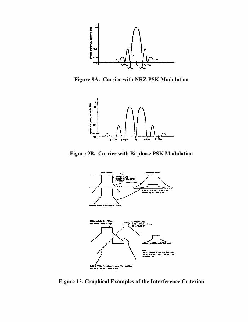
Figure 9A. Carrier with NRZ PSK Modulation
Figure 9B. Carrier with Bi-phase PSK Modulation
Figure 13. Graphical Examples of the Interference Criterion
i ....
i l~A I~
INTUtF'lfl[IK( ,11oouc10 IY A TIUNSMITI(II M IJI AD.IA• INT l,ri[OIJt:NCT
(\,-
-·· TC STIIAIQHT IL~S IN TH[ LOO ,LOTS '"[ ,011 COHV(JUENC[ IN LLU&TlllATION

Figure 10a. Theoretical PCM NRZ Spectrum at 7.5 k b/s
Figure 10b. PCM NRZ Spectrum With 4 kHz RRB at 7.5 k b/s
• Hi:. ·1 ------·,---·, ..... ..... ...... ...... ...... •ll ·······-----------------·-------·
! r, •ZO
i I s ! •SO
.§ ,I
a .: ... !' i
....... I I I •...... ....... ::::::: .::. :::::::. .... . •••••••• I •• •••••••• •••••• I •n
~mmr;~EirHHi°~fi=~·, ==· -----·i------.......... .,. .. ,.,...,.,,.,.,c, .... e e:i. .. •• eeo• ••• ······~· •••• ,,..#(-..0"'""· ••••• ...... ••• • •• •••••••• ........... ~10......... ....... ••••• •••• ••• ::: :::::::! ::;;~~:t ::::::: :::::! I ::::: ::::: I ::::. • ••• • • •• • •••- •., -,, ... .., ..... • """ • _ ..... "" •• ..... ,..., ... __ ., ••••-•-••o•• -•• •••·• •••••••• •"""'"""l,;,ue"'*"* •"'-'"'""*lo-, .. ,.,.. eoe.ae J ••o•• ••••• I :::::::: =~~~;;~l::~;;:: ::!:::~!~~:~:;: ::.::::.I.:::~: ::::: . :::::::: : ::!:;:\ ::::~:: :::~::: I ::::c::;: :~~::::I:.:::~:: .:::::.1 :::::::: ::::::::::::::: :~:;~::::::~:::: :::~:::i':::~7.:: :::::::, •••••••• •ca;;o..,[ ,. .... ., .... •'-·-=•-'• [ ..,,.. • .,.,,. • ..,.,.,.,~..,,., ,.,,..,_,.,'I<• • ..,.,,.••• f •••••••• .. •••'•=•I.,,..,.,. •• :=="=""', .... .,..,., ..... ,,.,.,..,.,I •o ,...,.,,,. 00 .. 00001 • ••• o-.•eo-c:: """ ... • ,.., ",..,,... _, = 0 """" •*"'""'"'" • _.,,. 0 ==•o •• ... e,;,,:, •-•=""'•••• ••••o••• ,..,"..,""" [ o'""'"""" .. .,.: .. ~.,_..,I ... ., ............. o:,,;,110 '"""•"""' es ... •o•o I •••••c•o e.a:ca•=,;a f O-" """"• •'-"'-'-"&"'I"'""""''""'" ..,.,.,..,,..,.,; ! o.,.;,.o""'" sca .. 0001 •••••••• ••.::."'"'""'1 ";;,"e.a"" ... _.,..,., l"' I .. .,,.,.,..,., "'""'""'"'"I"""."'"• •"""~*•I :::::::: ::~::;;) :::;;:: ::~~~;~ ! ~~=~=~= =~~;;;~ { ;;.~~~== :;:;::: l •••••c•• •s.,s;""' I"'"''""'''"'"" c,.. . .,.,=.,= I .. ,,,., .. ,..-.:,,. •'="""'",..1 '11.0:\'UU•O oll::tc••c,:,, I
,: :::::::: :::;,~::1 ::::::: :~~:::: l :~::::: :::::::I::~:::~ :~::::: I !: •SO ••••••;,,•-•="'="'"'"•-''-'"c."""'"-=.:"""".,,,.+.,ocoo., .. _.,.,..,..,..,"'• ·,;,,:;.;.,c=-oa",:a"co.+ I •••••e•• .,.,..,,,.,.,.,I••*-'-"""' *'"""'"'",:, l • .,.,...,.,.,.,. """"''"'""""'' """"'"'"* •"o"*"* I ~ :::::::: ::~::::1 !~:;;~: :::~~~:I~:~~~:~ ~::::::: ::::~:: :~::::: f
•••••••• ••=*""'"i """''""'·•"' •C-'C. .. :::, J .;"*"-"O..> ........ ,,.Q ( <&o-,s,:,,.....,. 0,;a='-'• .. • J to •••••••• •"-'"'-"=•1,u,c;•;o •::i::,;,..a..>f"""'"'"'"''" ::,,.,i,.,,,.,..01,;a,..c«e:,;, .. :..>oo••I
.. I_ :::::::: ::::::::1 :~::::: ::~::::I=~~~~:: ::~:!:: 1 :;~~~:: :;::::! I
•••••••• .,..,c•o-.01 •""'"'""• •Cca.S10,i, 1.:.::,:,;o"""' .,...,::,.,.,,..,., .,",.,_~,,.,,""' •=o ... c,o-o I
..... ::::::::_ ::::::: l :::~::: _:~::::: ! ~:~ =~: :_ ::::;~: ~ :::~.~ ==-=:~ ~:::! •••••11-00 "'"'=•.,•=I • .,.......... "'·'"-'":::a 1 "'""'"'.,'-'a;,"' ,;, ""''"'"""' """,;.,,a;•;..• c.:«ao•o;:. t ••••••::,9 oc::,:.>=of c,..,.,.,.,,,. •"'"'"'"-"*To"'"'"'"'"'"' ,;, .... ,.,""' r ,., ... ~ . .,,... •• .,.,_..,,,.. • ., I ••••oo-·" ,.._..,.,,.c;,tc,~"-'"""' ... ..,., .;,<>O:j.c.or. ..... o.,,... .,,.,.,,.,,..,..,..,,..,,..,"' .. " c"oo .. u•f ::::::.;: ::;;;~~I~~:;;:!: !-~i;~:: I~:::::: ::.:::~: 1 :::~~:: ;::;;:: l •••••••• co ... co,;,:( ,HI .,,..o::,• cac;r= .. ,:u, f o ........ ., a accco,.,.;, J aq..-,;,noe '"""""•• I ••••••o., e,;:o•o" I""".,•"-• "'""'---001 co ·'"''""', ,,.,,;,,.,..,,..I"'"'"-"~'-'• c,;,.;,;a,,oo t
:::::::: ::::::::: :::~:~: :~~::~:I::~:::: ::;::;i l ~:~~~:: :;:;::: l •••••••••o 111<••• o•c••••••• ••• coaao,;,,.,e\OO•••u••o••• ,,.,;, "'•••-• "•••••••-..• , ts Ja 4$ 10
hequenc, :la kHz

Figure 11. One-sided Profile Representation of Necessary Bandwidthand Power Level Limit
Figure 12. Asymptotic Behavior of Spectrum Spreading Factor F,for a 4 KHz Reference Bandwidth
M
5 > • .. . ii 0:
~g o.., .. ". 3 .. .. .!, IC X ;~ ff a: >. 1-Z ii 2 ZI-.. :, oc: -'l!l : 0: .... Uu "'z .... .. 0:
~~ gr LC
!i
ii • -..
AdJoc1nt lt1-b1ncl A11l9nm•:i_
r ~~ 0 4-"""'--.----. Ref LIYII I NOTES:
-10
-zo
-50
•40
•IO
-,o 0
'•
Required Dynamic Rant•
l I
I I
I
) I
I I
I I
I I
I
2
IIN·fcl/lfu·fc)
1.
2.
3.
tN-tc Is the one-sided "Necessary Bandwidth"; tu-re Is the
unattenuated bandwidth.
All epcctral measurements are referred to a Reference
Resolution Bondwidth.
Adjacent assigned frequencies and received power must be
1paced so as to preserve Required Dynamic Range for each
user under all conditions.·
4. Power Flux Density limitations refer to the reference level.
5. Dashed line ot adjacent assignment ahould be curved; It ls ahown straight for simplicity.
•18dB/OCTAVE
, .. RELATIVE FREQUENCY (f•f0 )/(tu ·f0 )
tONVOl.UTIONAL CODE
LIMIT WITHOUT CARRIEII 81-(J --------~----------' ,, NRZ ', ---------,-------',
' ' ' LIMIT WITH CARRIER--.....---... ',
••• '
NRZ 01..----------i------.:.ii------..--------------"f---------.... ---llCHZ 2KIIZ 4KHZ ',
81T RATE (LOGARITHMIC SCALE)

APPENDIX A
DEFINITIONS
The following definitions are provided for the reader’s convenience. They appear inpublications such as the International Radio Regulations, the OTP Manual, etc.
Authorized Bandwidth: the bandwidth appearing in the emission designator. TheAuthorized Bandwidth equals the Necessary Bandwidth.
Bandwidth: unless otherwise indicated, the Assigned Frequency Band. The AssignedFrequency Band equals Necessary Bandwidth plus twice the absolute value of thetransmitter frequency tolerance. The Assigned Frequency lies in the center of the AssignedFrequency Band.
Band: a specified range of frequencies. The following qualifiers are used most commonlyin the USA and appear in the OTP Manual.
a. Exclusive Band: a frequency band allocated on a primary basis to a single service.
b. Space Band: a frequency band allocated on a primary basis to the space service(s).
c. Terrestrial Band: a frequency band allocated on a primary basis to the terrestrialservice(s).
d. Shared Band: a frequency band allocated on an equal primary basis to more thanone service. This term is commonly used to indicate a band shared equally on aprimary basis between one or more space services and one or more terrestrialservices.
NOTE: For a discussion of the terms “primary”, “permitted”, and “secondary”services as applied in ITU usage, see RR Article 5, Sect. II, regulation no.137-140.
Conducted Measurement: a measurement made by means of a direct connection betweena measuring instrument and a transmitter. The measurement is made under conditions ofloading and other factors so as to reproduce the conditions encountered in actualoperation, and the results are presented as Power Spectral Density (see below).
Radiated Measurement: a measurement made without the use of a direct connectionbetween the measuring instrument and the transmitter. The measurement is made under

conditions which reproduce those encountered in actual operation, and is expressed interms of the EIRP within a Reference Resolution Bandwidth (see Section 6.1.1 of the OTPManual); i.e., the effective radiated Power Spectral Density relative to an isotropic emitter.Radiated measurements will be expressed in PFD units.
Radio Regulations (abbreviated RR): see 1968 edition of Additional Radio Regulations,Resolutions and Recommendations published by the General Secretariat of theInternational Telecommunications Union (ITU), Geneva, as revised by the WorldAdministrative Radio Conference for Space Telecommunications (WARC), Geneva, 1971.
Space Services: all services involving transmissions to or from any element of a SpaceSystem. All U.S. Government services are identified in the OTP Manual, Chapter 6,Section 6.1.2.
APPENDIX BPOWER FLUX DENSITY LIMITS AT THE EARTH’S SURFACE FROM
SPACE STATIONS
The power flux density limits at the earth’s surface specified below apply to space stationsoperating in the bands and for the services indicated. This table is based on data takenfrom the U.S. Government OTP Manual. The International Radio Regulation of the ITUcontain a somewhat more extensive table.
POWER FLUX DENSITY LIMITS AT THE EARTH’S SURFACEFROM SPACE STATIONS SHARING WITH THE FIXED AND
MOBILE SERVICES
Frequency Band MHz)
Space Radiocom-munication Service
Angle of arrival (*) abovethe horizontal plane in degrees
0E-5E 5E-25E 25E-90E
1670-1690
1690-1700
1700-17102200-2300
Meteorological-SatelliteMeteorological andEarth Exploration-Satellite (forcountries mentionedin ITU No. 354A)Space ResearchSpace Research
-154* -154+
-144*

7300-7750
7450-7550
Fixed-Satellite
Meteorological-Satellite
-152* -152+
-142*
8025-8400
8025-8400
8400-8500
Fixed-Satellite
Earth ExplorationSatelliteSpace Research
-150* -150 + -140*
21200-22000 Earth ExplorationSatellite
-115* -115 + * -105**
POWER FLUX DENSITY LIMITS AT THE EARTH’S SURFACE FROM SPACESTATIONS SHARING WITH THE METEOROLOGICAL AIDS SERVICE
1690-1700 Meteorological and -133 for all angles ofEarth Exploration- arrival***Satellite
POWER FLUX DENSITY LIMITS FROM SPACE STATIONS ATTHE RECEIVER INPUT OF A STATION IN THE FIXED SERVICE
USING TROPOSPHERIC SCATTER
1670-1700 Meteorological andEarth Exploration- -168 dBW referred to a 4 kHzSatellite Bandwidth
1700-1710 Space Research (see ITU No. 47ONGA)2200-2300 Space Research

POWER FLUX DENSITY LIMITS AT THE GEOSTATIONARY ORBITFROM SPACE STATIONS USING NON-GEOSTATIONARY ORBITS
8025-8400 Earth Exploration -174*Satellite
* Entries indicate Power Flux Density (PFD) in units of W/m2 /4 kHz, expressed indB relative to a 1 W signal passing through 1 square meter measured in a 4 kHzReference Resolution Bandwidth.
** Entries indicate PFD in units of W/m2 /1 MHz, expressed in dB relative to a 1 Wsignal passing through 1 square meter measured in a 1 MHz Reference ResolutionBandwidth.
*** PFD in units of W/m2 /1.5 MHz, expressed in dB relative to 1 W passing through 1square meter measured in a 1.5 MHz Reference Resolution Bandwidth.
APPENDIX CEXCERPTS FROM THE ITU RADIO REGULATIONS
The following items have been extracted for the readers’ convenience from the ITU RadioRegulations (with some editorial changes for clarity). The paragraphs below indicate themaximum permissable EIRP which may be transmitted horizontally by an earth stationoperating on an equal primary basis with terrestrial services in the spectral rangesindicated. Bands shared between other combinations of services on bases other than anequal primary basis are not subject to these limitations:
a. below 15.35 GHz
The EIRP transmitted toward any azimuth as a function of elevation 2 (see Fig. 5) by anearth station shall not exceed the following limits except as provided in (e) below:
+40 dBw in any 4 kHz band for 2#2E
+40 +(3 2) dBW in any 4 kHz band for 0E <2#5E (0.087 radians)
where 2 is the angle of elevation of measured radiation above the planeperpendicular to the local gravitational vector (the geoidal horizontal) passingthrough the centre of radiation of the antenna of the earth station and measured indegrees as positive above the horizontal plane and negative below it (see Fig. 6).

b. 15.35 GHz to 40 GHz (inclusive)
The EIRP transmitted toward any azimuth as a function of elevation angle 2 by an earthstation shall not exceed the following limits except as provided in (f) below:
+64 dBW in any 1 MHz band for 2#0E
+64 +(3 2) in any 1 MHz band for 0E<2 #5E (0.087 radians)
where 2 is as defined in (a) (see Fig. 7).
c. above 40 GHz, as a design objective only
The EIRP transmitted toward any azimuth as a function of elevation 2 by an earth stationshall not exceed the following limits:
64 dBW in any 1 MHz band for 2#0
64 dBW +(3 2) dBW in any 1 MHz band for 0 <2 #5E (0.087 radiars)
d. For angles of elevation 2 greater than 5E there shall be no restriction as to the EIRPtransmitted toward any azimuth by an earth station (see Figs. 6 and 7).
e. As an exception to the limits given in (a) above, the EIRP transmitted toward anyazimuth for elevation angle 2#5E by an earth station in the space research service (deepspace) shall not exceed +55 dBW in any 4 kHz band (see Figure 6).
f. As an exception to the limits given in (b) above, the EIRP transmitted toward anyazimuth for elevation angle 2#5E by an earth station in the space research service (deepspace) shall not exceed +79 dB (W/M2) in any 1 MHz band (see Figure 7).
All transmitters used in the Space Services must be commendable according to therequirements stated in the ITU Radio Regulations, Article 7, Section IX:
Cessation of Emissions
470V 24. Space stations shall be fitted with devices to ensure immediate cessation oftheir radio emissions by telecommand, whenever such cessation is requiredunder the provisions of these Regulations.

1 Spa2 In the case of space stations on geosynchronous satellites having an angle of inclinationgreater than 5 degrees the positional tolerance shall relate to the nodal point.
2 470e.1The level of unacceptable interference shall be fixed by agreement between theadministrations concerned, using the relevant C.C.I.R. Recommendations as a guide.
Control of Interference between Geostationary-Satellte Systems and non-synchronousinclined Orbit-Satellite Systems
470VA 25. Non-geostationary space stations in the fixed satellite service shall cease orreduce to a negligible level radio emissions, and their associated earthstations shall not transmit to them, whenever there is insufficient angularseparation between the non-geostationary satellite and geostationarysatellites and unacceptable interference to geostationary satellite spacesystems operating in accordance with these Regulations. (The level ofunacceptable interference shall be fixed by agreement between theadministrations concerned, using the relevant C.C.I.R Recommendations asa guide).
The following requirements from the ITU Radio Regulations should be observed asappropriate by the Space Services:
Spa2 Station Keeping of Space Stations1
470VBSpa2
26. Space stations on geostationary satellites:
470VCSpa2
shall have the capability of maintaining their positions within ±1 degreeof the longitude of their nominal positions , but efforts should be made toachieve a capability of maintaining their positions at least within ±0.5degree of the longitude of their nominal positions;
470VDSpa2
shall maintain their positions within ±1 degree of longitude of theirnominal positions irrespective of the cause of variation; but
470VE need not comply with No. 470VD as long as the satellite network towhich the space station belongs does not produce an unacceptable levelof interference2 into any other satellite network whose space stationcomplies with the limits given in No. 470VD.

3 The level of unacceptable interference shall be fixed by agreement between the administrationsconcerned, using the relevant C.C.I.R. Recommendations as a guide.
SPA2 Pointing Accuracy of Antennae on Geostationary Satellites
470VF 27. The pointing direction of maximum radiation of any earth-ward beam ofantennae on geostationary satellites shall be capable of being maintainedwithin:
10% of the half power beamwidth relative to the nominal pointingdirection, or
0.5 degree relative to the nominal pointing direction, whichever isgreater. This provision applies only when such a beam is intended forless than global coverage.
In the event that the beam is not rotationally symmetrical about the axis ofmaximum radiation, the tolerance in any plane containing this axis shall berelated to the half power beamwidth in that plane.
This accuracy shall be maintained only if it is required to avoidunacceptable interference3 to other systems.
Spa.2 Power Flux Density at the Geostationary Satellite Orbit
470VG 28. In the frequency band 8 025 to 8 400 MHz, which the Earth exploration-satellite service using non-geostationary satellites shares with the fixed-satellite service (Earth-to-space) or the meteorological-satellite service(Earth-to-space), the maximum power flux density produced at thegeostationary satellite orbit by any earth exploration-satellite service spacestation shall not exceed -174 dBW/m2 in any 4 kHz band.
REFERENCES
1. STDN User’s Guide Baseline Document (latest revision) by J. N. Scott, STND No.101.1, available to potential users of the NASA data acquisition network from:Requirements and Plans Office, Code 801, Goddard Space Flight Center, Greenbelt,Maryland 20771
2. Lindsey, W. C. and Simon, Marvin K., “Telecommunications Systems Engineering”,Prentice-Hall, Inc., 1973