SOLYS2 2-Axis Sun Tracker Instruction Manual · The SOLYS 2 two-axis sun tracker is an all-weather...
66
Instruction Manual 2-Axis Sun Tracker Rev. 04/14 SOLYS 2
Transcript of SOLYS2 2-Axis Sun Tracker Instruction Manual · The SOLYS 2 two-axis sun tracker is an all-weather...

Instruction Manual
2-Axis Sun TrackerRev. 04/14
SOLYS 2


Throughout the manual and on the SOLYS 2 instrument symbols are used to indicate to the user important information. The meaning of the symbols located on the SOLYS 2 is as follows:
Caution (refer to accompanying documents) Caution, risk of electric shock
Protective conductor terminal DC (Direct Current) AC (Alternating Current)
The meaning of the symbols located inside the SOLYS manual 2 is as follows:
Important, indicating a point of consideration.
Caution, risk of electric shock, always connect a protected earth Note: Useful information for the user Tip: Useful information for the user

EC TYPE DECLARATION OF CONFORMITY We: Kipp & Zonen B.V. Postbus 507 2600AM Delft The Netherlands Declare under our sole responsibility that the product: Type: SOLYS 2 Name: Sun tracker To which this declaration relates is in conformity with European Harmonized Standards as published in: Official Journal of the EC: Issue: C246 (05-10-2005) The compliance of the product has been based on: EN 61326-1:2000 Emissions and Immunity EN 61010-1:2001 Safety Following the provisions of the directive: EMC-directive: 2004/108/EC Electrical Safety: 65/2005/EC These conclusions are based on test reports: 1678/SOLYS/EMC 1678/SOLYS/LVD ce-test, qualified testing bv Kiotoweg 363 3047BG Rotterdam Delft, 08 February 2008 B.A.H. Dieterink President Kipp & Zonen B.V.

TABLE OF CONTENTS
IMPORTANT USER INFORMATION .............................................................................................................................. 1 EC Type DECLARATION OF CONFORMITY .................................................................................................................. 3 TABLE OF CONTENTS ................................................................................................................................................ 4 1 GENERAL INFORMATION ................................................................................................................................... 5
1.1 INTRODUCTION TO THE SOLYS 2 .............................................................................................................. 5 1.2 MANUAL ................................................................................................................................................... 5 2 SPECIFICATIONS OF THE SOLYS 2 .............................................................................................................. 6
3 INSTALLATION .................................................................................................................................................. 8 3.1 REQUIRED TOOLS FOR SOLYS 2 MOUNTING ............................................................................................. 9 3.1.1 REQUIRED TOOLS FOR SHADING BALL ASSEMBLY / SUN SENSOR .......................................................... 9 3.2 MINIMUM OPERATING AREA / CONSIDERATIONS ...................................................................................... 10 3.3 CREATE A FIRM BASE TO MOUNT THE TRIPOD STAND with the K&Z logo pointing East. ........................... 11 3.4 Mount the tracker on the tripod with the E on the mounting flange pointing East .................................... 12 3.5 Level the SOLYS 2 using the integrated bubble level and tripod feet ........................................................ 14 3.6 Connecting AC/DC Power ....................................................................................................................... 15 3.6.1 Connecting AC/DC Power Cable .......................................................................................................... 16 3.6.2 ENVIRONMENTAL CONDITIONS ............................................................................................................ 19 3.6.3 Using a SOLAR PANEL TO POWER SOLYS 2 ........................................................................................... 19 3.6.4 Enabling Power / Led STATUS .............................................................................................................. 20 3.6.5 Led STATUS ........................................................................................................................................ 20 3.7 Alignment of THE SOLYS 2 ...................................................................................................................... 22 3.8 Secure m8 bolts ...................................................................................................................................... 23 4 ACCESSORY INSTALLATION ..................................................................................................................... 24 4.1 Mounting Side Mounting Plate (For shading assembly or CHP 1 ............................................................... 24 4.2 Side Mounting Plate + Pmod-wrc pmo6 absolute cavity Pyrheliometer ..................................................... 25 4.3 Side Mounting Plate + Middleton SPO2 sun photometer .......................................................................... 26 4.4 Side Mounting Plate + Eppley (A)hf absolute cavity pyrheliometer ............................................................ 27 4.5 Attaching Pyrheliometer. ......................................................................................................................... 28 4.6 Mounting Sun sensor. ............................................................................................................................. 29 4.6.1 Alignment of Sun Sensor ..................................................................................................................... 32
4.7 Shading Ball Assembly .................................................................................................................... 33 4.8 Top Mounting plate assembly. ........................................................................................................ 37 4.9 Mounting Kipp radiometers without Ventilation unit. ...................................................................... 38 4.10 Mounting Kipp radiometers with Ventilation unit. ............................................................................ 39 4.11 Mounting Eppley radiometers with or without Ventilation unit. ........................................................ 40 4.12 Shading ball rods assembly. ............................................................................................................ 41 5 EXTRA ACCESSORIES. ..................................................................................................................... 43
5.1 Tilted Pyranometer mounting kit targeting the PV market. ...................................................................... 43 5.2 Small Top mounting plate for installing a single Kipp & Zonen radiometer. ............................................. 44
6 ETHERNET COMMUNICATION .......................................................................................................................... 45 6.1 EXTERNAL COMMANDS ........................................................................................................................... 49 6.2 Interfacing with thrid party applications .................................................................................................. 51
7 MAINTENANCE ............................................................................................................................................... 53 8 SOLVING PROBLEMS ........................................................................................................................................ 54
8.1 PROBLEM CHECK-LIST .............................................................................................................................. 54 8.2 FAQ ........................................................................................................................................................ 55
9 SOFTWARE OVERVIEW ..................................................................................................................................... 56 9.1 Algorithm ............................................................................................................................................... 56
10 FIRMWARE ...................................................................................................................................................... 57 10.1 Firmware upgrade ................................................................................................................................... 57
11 DRAWING SIDE MOUNTING PLATE ................................................................................................................... 59 12 DRAWING LARGE TOP MOUNTING PLATE ......................................................................................................... 60 13 HEIGHT SPECIFICATIONS SOLYS 2 INCLUDING INSTRUMENTS. .......................................................................... 61 14 PARTNUMBERS SHADING ASSEMBLY. ............................................................................................................... 62 15 HOW TO GUIDE THE CABLES ........................................................................................................................... 63 16 MOUNTING UVS INSTRUMENT ......................................................................................................................... 64

1 GENERAL INFORMATION
1.1 INTRODUCTION TO THE SOLYS 2 The SOLYS 2 two-axis sun tracker is an all-weather positioning platform used to point specialized instruments at the sun’s movement across the sky. It is fully automatic and does not require a computer or software for installation. The integrated GPS receiver automatically configures location and time data. Multi-colour LEDs indicate the operating status and an Ethernet port allows for software upgrades. The high-efficiency belt drive system requires no maintenance. The tough and distinctive cast aluminium housing has an integrated tripod stand with levelling feet. A side plate with mountings for a Kipp & Zonen pyrheliometer is included as standard and a second side plate can be fitted for an additional pyrheliometer. A top mounting plate is available for convenient mounting of up to three Kipp & Zonen radiometers. The shading assembly accessory includes the top mounting plate and allows the tracker to be configured as a complete solar monitoring station. SOLYS 2 does not suffer from internal clock drift because time is updated by the GPS receiver. A sun sensor is optional available for active tracking where the stability of the support platform cannot be guaranteed. SOLYS 2 has been designed to provide reliable, affordable sun tracking for small and medium sized payloads. (<20Kg) Its accuracy is excellent for solar monitoring applications.
The built in power supply accepts both 24 VDC and 90 – 264 VAC and allows the DC Voltage to be used as a backup. SOLYS 2 is an all weather instrument providing optimal performance even in the harshest climates (from equatorial to Polar region). The built in heater extends the operating temperature down to -40°C and operates from AC power only. The SOLYS 2 features high accuracy, resolution and repeatability. A standard SOLYS 2 with no accessories is shown in Figure 1.1.
Figure 1.1: SOLYS 2 standard delivery
1.2 MANUAL The SOLYS 2 INSTRUCTION MANUAL is intended for customers who have purchased the SOLYS 2 with some
or all of the accessory items that can be used to enhance or expand its capabilities. It includes all the information necessary to install and operate the SOLYS 2 for stand-alone operation.
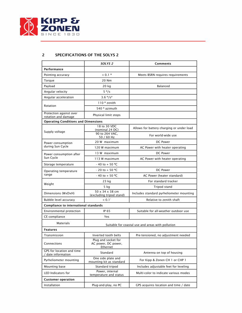
2 SPECIFICATIONS OF THE SOLYS 2
SOLYS 2 Comments
Performance
Pointing accuracy < 0.1 º Meets BSRN requires requirements
Torque 20 Nm
Payload 20 kg Balanced
Angular velocity 5 º/s
Angular acceleration 3.6 º/s²
Rotation 110 º zenith
540 º azimuth
Protection against over rotation and damage
Physical limit stops
Operating Conditions and Dimensions
Supply voltage
18 to 30 VDC (nominal 24 DC) Allows for battery charging or under load
90 to 264 VAC, 50 / 60 Hz
For world-wide use
Power consumption during Sun Cycle
20 W maximum DC Power
120 W maximum AC Power with heater operating
Power consumption after Sun Cycle
13 W maximum DC Power
113 W maximum AC Power with heater operating
Storage temperature - 40 to + 50 ºC
Operating temperature range
- 20 to + 50 ºC DC Power
- 40 to + 50 ºC AC Power (heater standard)
Weight 23 kg For standard tracker
5 kg Tripod stand
Dimensions (WxDxH) 50 x 34 x 38 cm (excluding tripod stand)
Includes standard pyrheliometer mounting
Bubble level accuracy < 0.1° Relative to zenith shaft
Compliance to international standards
Environmental protection IP 65 Suitable for all-weather outdoor use
CE compliance Yes
Materials
Suitable for coastal use and areas with pollution
Features
Transmission Inverted tooth belts Pre-tensioned, no adjustment needed
Connections Plug and socket for
AC power, DC power, Ethernet
GPS for location and time / date information
Standard Antenna on top of housing
Pyrheliometer mounting One side plate and
mounting kit as standard For Kipp & Zonen CH 1 or CHP 1
Mounting base Standard tripod Includes adjustable feet for leveling
LED Indicators for Power, internal temperature and status
Multi-color to indicate various modes
Customer operation
Installation Plug-and-play, no PC GPS acquires location and time / date
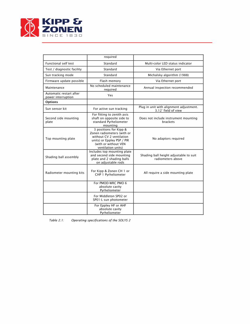
required
Functional self test Standard Multi-color LED status indicator
Test / diagnostic facility Standard Via Ethernet port
Sun tracking mode Standard Michalsky algorithm (1988)
Firmware update possible Flash memory Via Ethernet port
Maintenance No scheduled maintenance
required Annual inspection recommended
Automatic restart after power interruption Yes
Options
Sun sensor kit For active sun tracking Plug in unit with alignment adjustment. 3.12° field of view
Second side mounting plate
For fitting to zenith axis shaft on opposite side to standard Pyrheliometer
mounting
Does not include instrument mounting brackets
Top mounting plate
3 positions for Kipp & Zonen radiometers (with or
without CV 2 ventilation units) or Eppley PSP / PIR
(with or without VEN ventilation units)
No adaptors required
Shading ball assembly
Includes top mounting plate and second side mounting plate and 2 shading balls
on adjustable rods
Shading ball height adjustable to suit radiometers above
Radiometer mounting kits For Kipp & Zonen CH 1 or CHP 1 Pyrheliometer
All require a side mounting plate
For PMOD-WRC PMO 6
absolute cavity Pyrheliometer
For Middleton SP02 or SP01-L sun photometer
For Eppley HF or AHF
absolute cavity Pyrheliometer
Table 2.1: Operating specifications of the SOLYS 2

3 INSTALLATION
The following sections provide information on the installation of the SOLYS 2. The installation consists of the following steps which will be explained step by step in the sub chapters: 3.1 Required tools for SOLYS 2 mounting 3.1.1 Required tools for Shading Ball Assembly / sun sensor 3.2 Minimum operating area / considerations 3.3 Create a firm base to mount the tripod stand with the K&Z logo pointing East 3.4 Mount the tracker on the tripod with the E on the mounting flange pointing East 3.5 Level the SOLYS 2 using the integrated bubble level and tripod feet 3.6 Connecting AC/DC Power 3.7 Alignment of the SOLYS 2 3.8 Fasten tripod feet to the firm base and check alignment. 4.1 Mounting second Side Mounting Plate (optional) 4.5 Attaching Pyrheliometer (optional) 4.6 Mounting Sun sensor (optional) 4.6.1 Alignment of Sun Sensor (optional) 4.7 Shading Ball Assembly (optional) 4.8 Top mounting plate assembly (optional) 4.9 Mounting Kipp radiometers without Ventilation unit (optional) 4.10 Mounting Kipp radiometers with Ventilation unit (optional) 4.11 Mounting Eppley radiometers with/without Ventilation unit (optional) 4.12 Shading ball rods assembly. (optional) Apart from the creation of the tripod support base and the assembling of the accessories and instruments, the levelling and the fine adjustment is only a matter of minutes. However a clear sun is required to do this. It is important that these steps are carried out in this order. SOLYS 2 has various accessories to enhance and expand its operation, including:
• Top Mounting Plate • Extra Side Mounting Plate • Pointing & Shading Ball Assembly:
Including one extra Side Mounting Plate and a Top Mounting Plate. • Sun Sensor • Mounting kits for various instruments for direct solar radiation measurement. • Ventilation units for Pyranometers/Pyrgeometers

3.1 REQUIRED TOOLS FOR SOLYS 2 MOUNTING
For installation on site the following materials are supplied with the SOLYS 2 Allen Wrench key type 6 (for M8 bolts for tripod) Allen Wrench key type 3 Allen Wrench key type 2.5 Screws M8 x 20 plus M8 washers
Required but not supplied are:
Screwdriver for connection of power cable to the connector Cable for power connection of the SOLYS 2 Compass to find geographical East.
3.1.1 REQUIRED TOOLS FOR SHADING BALL ASSEMBLY / SUN SENSOR
The tools required for the mounting of the shading ball assembly are supplied with this option.
Required but not supplied are: A Ruler, to measure the position of the optional sun sensor.
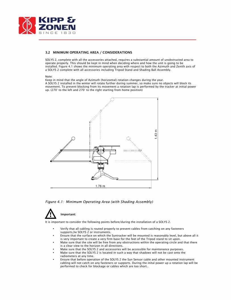
3.2 MINIMUM OPERATING AREA / CONSIDERATIONS SOLYS 2, complete with all the accessories attached, requires a substantial amount of unobstructed area to operate properly. This should be kept in mind when deciding where and how the unit is going to be installed. Figure 4.1 shows the minimum operating area with respect to both the Azimuth and Zenith axis of a SOLYS 2 complete with all accessories including Tripod Stand and Shading Ball Assembly. Note: Keep in mind that the angle of Azimuth (horizontal) rotation changes during the year. A SOLYS 2 installed in the winter will rotate further during summer, so make sure no objects will block its movement. To prevent blocking from its movement a rotation lap is performed by the tracker at initial power up. (270° to the left and 270° to the right starting from home position)
Figure 4.1: Minimum Operating Area (with Shading Assembly)
Important:
It is important to consider the following points before/during the installation of a SOLYS 2.
• Verify that all cabling is routed properly to prevent cables from catching on any fasteners
supports,he SOLYS 2 or instruments. • Ensure that the surface on which the Suntracker will be mounted is reasonably level, but above all it
is very important to create a very firm base for the feet of the Tripod stand to sit upon. • Make sure that the site will be free from any obstructions within the operating circle and that there
is a clear view to the horizon in all directions. • Make sure that the SOLYS 2 and accessories will be accessible for maintenance purposes. • Make sure that the SOLYS 2 is located in such a way that shadows will not be cast onto the
radiometers at any time. • Ensure that before operation of the SOLYS 2 the Sun Sensor cable and other mounted instrument
cabling will not catch on any fasteners or supports. During the inital power up a rotation lap will be performed to check for blockage or cables which are too short..
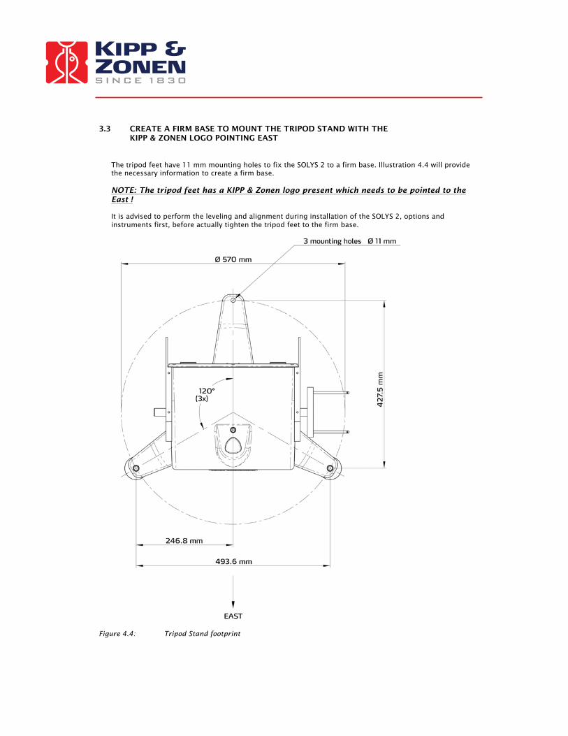
3.3 CREATE A FIRM BASE TO MOUNT THE TRIPOD STAND WITH THE KIPP & ZONEN LOGO POINTING EAST
The tripod feet have 11 mm mounting holes to fix the SOLYS 2 to a firm base. Illustration 4.4 will provide the necessary information to create a firm base. NOTE: The tripod feet has a KIPP & Zonen logo present which needs to be pointed to the East ! It is advised to perform the leveling and alignment during installation of the SOLYS 2, options and instruments first, before actually tighten the tripod feet to the firm base.
Figure 4.4: Tripod Stand footprint

3.4 MOUNT THE TRACKER ON THE TRIPOD WITH THE E ON THE MOUNTING FLANGE POINTING EAST
The SOLYS 2 is supplied with a standard ∅ 102 mm bottom flange, which has a 3-hole M8 mounting pattern to match the Tripod Stand with leveling feet. The tripod has 3 slots for mounting the 3 M8 bolts to the bottom flange. Both the E mark on the bottom flange and the K&Z logo on the tripod must point East when the SOLYS 2 is mounted. Ideally the bolts should be in the middle of the slots when the tripod is mounted to the SOLYS 2. This allows fine tuning the position afterwards
Note: Turn in the M 8 bolts by hand but do not fasten during first installation. Only after the alignment with the sighting target on the pyrheliometer (bracket) they need to be fastened. (chapter 3.7)
Remember that sun is required for this alignment.
Figure 4.2: Mounting the SOLYS 2 on the Tripod Stand
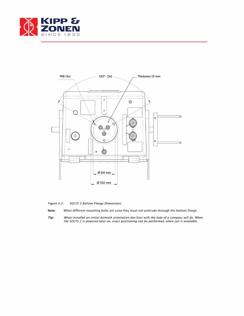
Figure 4.3: SOLYS 2 Bottom Flange Dimensions.
Note: When different mounting bolts are used they must not protrude through the bottom flange Tip: When installed an initial Azimuth orientation due East with the help of a compass will do. When
the SOLYS 2 is powered later on, exact positioning can be performed, when sun is available.

3.5 LEVEL THE SOLYS 2 USING THE INTEGRATED BUBBLE LEVEL AND TRIPOD FEET
Prior to activating the SOLYS 2, it must be levelled on its mounting surface. To help accomplish this task, the SOLYS 2 is equipped with a high accuracy bubble on top of the housing. Adjust the levelling feet on the tripod stand to move the bubble into the centre of the level. The levelling feet can be easily adjusted using a 13 mm wrench. The accuracy of the SOLYS 2 is within 0.1°when the bubble is within the circle.
We recommend during installation to keep the bubble inside the ring for both the SOLYS 2 and the Pyranometers. If however the bubble is half out of the ring, the instruments (Pyranometer and SOLYS 2) are still within 0.1 ° (BSRN requirement)
3.6 CONNECTING AC/DC POWER
CAUTION, RISK OF ELECTRIC SHOCK, ALWAYS CONNECT A PROTECTED EARTH
Important: Power supply
SOLYS 2 can be operated on either 115/230 VAC or 24 VDC. In case both the AC and DC supplies are present and the AC power is within its operating range (90 – 264 VAC) the SOLYS 2 will use the AC power. If the AC power fails and DC power is present the SOLYS 2 will without interruption continue on DC power. Inside the SOLYS 2 a 4 A slow blow fuse is used for the internal heater.
Important: Operating Temperature SOLYS 2 has an operating temperature range of -20°C to +50°C when operating on 24 VDC. When AC power is applied the standard built-in heater will be used. The use of the heater extends the operating temperature to - 40°C. The internal heater automatically switches on below 5ºC. If the SOLYS 2 is first started below -20°C it can take up to 30 minutes before the interior is above - 20°C and the SOLYS 2 will start. Table 4: SOLYS 2 Operating Temperature Range.
SOLYS 2 operating on DC power (heater not functional) -20°C to +50°C
SOLYS 2 operating on AC power (heater operational) -40°C to +50°C
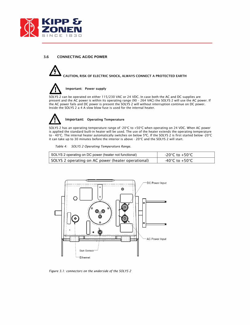
Figure 3.1: connectors on the underside of the SOLYS 2

3.6.1 CONNECTING AC/DC POWER CABLE This section will explain how to make and connect your power cable to power the SOLYS2.
Important Rotation lap Please understand that by applying power to the SOLYS 2 it will trigger a routine initialization
procedure. During this procedure it will check for GPS signal, make a 540° rotation and stops in home position for a complete minute.
Therefore it’s advisable to actually apply the power while checking chapter 3.6.4 SOLYS 2 is supplied with 2 waterproof power connectors, for both AC and DC. These connectors are in accordance with safety regulations for outdoor usage. The voltage drop over the cable should not cause the supplied voltage to be out of specifications.
Both the AC and DC connector are suitable for cable diameters between 6 and 12 mm. For 6 – 9 mm and 9 – 12 mm different sealing rings are used.
The AC connector is female type Hirschmann CA 3 LD connector. The DC connector is a male type Hirschmann CA 3 LS connector.
Illustration 3.2 indicates the pin numbers, where pin three is NOT used
Figure 3.2: pin numbering in male and female power connectors
For AC power: Pin 1: L1 Pin 2: N Pin Earth = Protected Earth
For DC power: Pin 1: +24Vdc Pin 2: GND Pin Earth = Protected Earth
Drawings for both connectors and pin numbers including types of cable are given in fig 3.4 and fig.
3.5. The pin numbers and ground connection for the individual wires are visible inside the connector. The ground connection is raised slightly above the other connections.

21
mm
5 m
m
Power cable for outdoor use (not included)Outer diameter: 6 - 12 mmNo. of conductors: 3
Conductor colors: Blue, Brown, Green/Yellow
Female connector (included)Hirschmann: CA 3 LDCable connections: 1 = Brown (L)2 = Blue (N) = Green/Yellow (Protective Earth)9 - 12 mm
6 - 9 mm
Power cable for outdoor use (not included)Outer diameter: 6 - 12 mmNo. of conductors: 3
Flexible wires:
Conductor colors: Red, Brown, Green/Yellow
Figure 3.4: Power Cable Connector for 90 – 264 VAC

21
mm
5 m
m
9 - 12 mm
6 - 9 mm
Male connector (included)Hirschmann: CA 3 LSCable connections: 1 = Red (+ 24 VDC)2 = Black (24 VDC GND) = Green/Yellow (Protective Earth)
Power cable for outdoor use (not included)Outer diameter: 6 - 12 mmNo. of conductors: 3
Flexible wires:
Conductor colors: Red, Brown, Green/Yellow
Figure 3.5: Power Cable Connector for 24 VDC
3.6.2 ENVIRONMENTAL CONDITIONS
Important: SOLYS 2 rear cover
SOLYS 2 does not contain any user serviceable parts inside. Therefore it is advised not to open the rear cover. Doing so can defeat the internal optical sensors which may result in physical damage to the SOLYS 2 and/or any attached equipment. Such damage is not covered under warranty.
Important: Precipitation
With the SOLYS 2 rear cover installed properly such that all 8 screws are secured, the SOLYS 2 is environmentally protected to IP65, according EN 60529: 1991 + CI 1993. This qualifies the SOLYS 2 to be used in weather conditions with all types of precipitation.
Important: Circuit breaker
A power on/off switch is not a part of the SOLYS 2; requirements for electrical equipment installed outdoors specify that:
• A power isolator (switch or circuit-breaker) must be included in the cable installation. • The isolator (switch or circuit-breaker) must be in close proximity to the equipment and within easy
reach of the operator. • The isolator (switch or circuit-breaker) must be marked as the power disconnection device for the
equipment. used in weather conditions with all types of precipitation.
3.6.3 USING A SOLAR PANEL TO POWER SOLYS 2 If the system is operating on solar power only, please be aware of the reduced number of hours of sunlight during the winter On cloudy days less than 50% of the normal radiation comes in Rule of thumb is to use 10 times as much solar panel power. How to determine what kind of solar panel is required; Please add the power consumption of each additional instrument, PC`s, data logger or any other device together with the power consumption of the SOLYS2 and multiply this by 10. Power consumption SOLYS 2 on DC : 20W during sun cycle. After the sun cycle, the SOLYS 2 will start its energy savings program and put itself to sleep mode. During this sleep mode the power consumption is 13W. 20 minutes before the sun rises, the SOLYS 2 will wake up, go to its home position and starts its active tracking mode with full power consumption. If no other power is available, also a few days without sun should be covered by the back-up battery. If the backup batteries are 2x12 V, they can be used in series for the SOLYS 2 (24 V)
3.6.4 Enabling Power / Led STATUS After the SOLYS 2 has been levelled (3.5), the power cable is assembled (3.6) the power can be switched on. The SOLYS 2 will start its initializing mode. During this initializing mode, the SOLYS 2 will check for any hardware errors, presence of the GPS signal, and in additional it will make an orientation lap to check for any blockades and to check if the cable length of the SOLYS 2 (and possible instruments) is sufficient. This rotation will be performed each time the SOLYS2 is powered up.
Important: -The orientation lap was added in software version released at the end of 2009. -Before the orientation lap starts, the SOLYS 2 will stand still for one minute in its home position. Experienced users can use this one minute of time to mount an optional side mounting plate. (chapter 4.1)
-During the orientation lap, the SOLYS 2 will move 270° to the left starting at home position, and will move 270° to the right starting at home position. Please make sure the cables have the correct length to perform this test
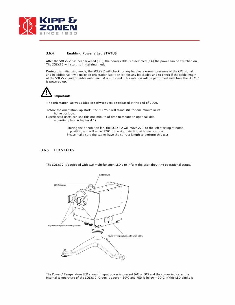
3.6.5 LED STATUS The SOLYS 2 is equipped with two multi-function LED’s to inform the user about the operational status.
The Power / Temperature LED shows if input power is present (AC or DC) and the colour indicates the internal temperature of the SOLYS 2. Green is above – 20ºC and RED is below – 20ºC. If this LED blinks it
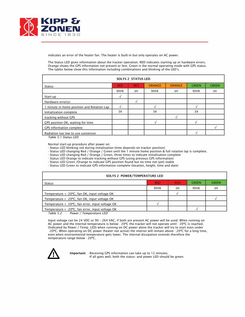
indicates an error of the heater fan. The heater is built-in but only operates on AC power. The Status LED gives information about the tracker operation. RED indicates starting up or hardware errors; Orange shows the GPS information not present or lost. Green is the normal operating mode with GPS status. The tables below show this information including combinations and blinking of the LED’s.
SOLYS 2 STATUS LED
Status RED RED ORANGE ORANGE GREEN GREEN
blink on blink on blink on
Start-up √
Hardware error(s) √
1 minute in home position and Rotation Lap √ √ √
Initialization complete 3X 3X 3X
tracking without GPS √
GPS position OK, waiting for time √ √
GPS information complete √
Radiation too low to use sunsensor √
Table 5.1 Status LED Normal start-up procedure after power on: - Status LED blinking red during initialisation (time depends on tracker position) - Status LED changing Red / Orange / Green until the 1 minute home position & full rotation lap is complete. - Status LED changing Red / Orange / Green, three times to indicate initialisation complete - Status LED Orange to indicate tracking without GPS (using previous GPS information) - Status LED Green /Orange to indicate GPS position found but no time not (yet) stable - Status LED Green to indicate GPS information complete (location, height, time and date)
SOLYS 2 POWER/TEMPERATURE LED
Status RED RED GREEN GREEN
blink on blink on
Temperature < -20ºC, fan OK, input voltage OK √
Temperature > -20ºC, fan OK, input voltage OK √
Temperature < -20ºC, fan error, input voltage OK √
Temperature > -20ºC, fan error, input voltage OK √
Table 5.2 Power / Temperature LED Input voltage can be 24 VDC or 90 – 264 VAC, if both are present AC power will be used. When running on AC power and the internal temperature is below - 20ºC the tracker will not operate until - 20ºC is reached. (Indicated by Power / Temp. LED) when running on DC power alone the tracker will try to start even under -20ºC. When operating on DC power (heater not active) the interior will remain above - 20ºC for a long time, even when environmental temperature gets lower. The internal dissipation extends therefore the temperature range below - 20ºC.
Important: -Receiving GPS information can take up to 12 minutes. -If all goes well, both the status- and power LED should be green.

3.7 ALIGNMENT OF THE SOLYS 2
Important: Before starting the alignment please verify certain issues: -The M8 bolt which hold the tripod to the actually sun tracker should not be tightened (only by hand) -SOLYS 2 has to be leveled (3.5) -SOLYS 2 needs to be supplied with an power source (3.6) -The status LED has to be green to indicate it has received all GPS information. (3.6.5) -The power LED has to be green to indicate a correct temperature, fan and input voltage. (3.6.5) -Sun sensor is NOT connected. (yet) When these requirements are met, the final adjustment can be made by rotating the SOLYS on its tripod until the sun falling through the first alignment target hole makes a round spot of light around the second alignment target hole. (see illustration 4.5) The vertical adjustment of the side mounting plate is a factory setting and should be OK. If the side mounting plates have been loosened or removed adjust the zenith position as well until the alignment target points at the sun and fasten the screws in the side mounting plates.
Figure 4.5: Alignment targets
Important: -Repeat this alignment after mounted the Pyrheliometer (chapter 4.5) The CHP 1 Pyrheliometer also has two alignment targets holes which can be used for a second alignment. Because of the larger distance between the alignment holes, these are slightly accurate than on the mounting clamps.

3.8 SECURE M8 BOLTS
After the SOLYS 2 is levelled, aligned, it’s time to fix the tripod feet to its firm base. Please perform a re-check of the levelling and alignment after the tripod feet is attached to its base. Tip: After the SOLYS 2 is levelled and properly secured recheck all radiometers for proper alignment
and levelling.

4 ACCESSORY INSTALLATION This chapter provides all the information on the accessory installation of all possible SOLYS 2 accessories and instruments.
4.1 MOUNTING SIDE MOUNTING PLATE (FOR SHADING ASSEMBLY OR CHP 1 Tip: Use the 1 minute in home position to mount the (second) side mounting plate. (A power reboot will send the tracker to home position) The SOLYS 2 is supplied as standard with one Side Mounting Plate. This plate is factory installed in the correct position and needs no readjustment. A second Side Mounting plate is used in conjunction with the Shading Ball Assembly or for mounting a second Pyrheliometer. The supplied plates can be customized to meet your specific configuration requirements. For alignment of the second mounting plate a clear sun is required to adjust the position on the axis. During normal operation (SOLYS 2 turned on) the position of the side mounting plate can be fixated when the alignment target on the mounting clamps (or Pyrheliometer) The hole pattern of the Side Mounting Plate is given in figure 4.6. If the second side mounting plate is used to mount the shading drive arm (without instrument mounting clamps) this drive arm should be aligned with the first one before fixating the screws on the axis. SOLYS 2 and can handle payloads up to 20 Kg including all accessories.
• Turn off power to the SOLYS 2 • Pre-assemble the Side Mounting Plate as shown in figure 4.6 and attach the Side Plate Assembly to
the Zenith shaft. Ensure that the plate is pushed up against the end of the Zenith shaft. • Check the circular bubble level once more to verify that the SOLYS 2 is still properly leveled. • Use the alignment target to position the side mounting plate to the sun. This requires that the
SOLYS 2 is running and a clear sun is present, or allign the second shading arm with the first one. (as described under Shading Ball Assembly)
• Tighten the two M6 screws inside the Side mounting Plate to securely clamp it to the shaft. (use wrench #3)
Figure 4.6: Assembling Side Mounting plate with CH(P) 1pyrheliometer mounting kit

4.2 SIDE MOUNTING PLATE + PMOD-WRC PMO6 ABSOLUTE CAVITY PYRHELIOMETER
Figure 4.20: Installation of PMOD-WRC PMO6 Absolute cavity Pyrheliometer on side mounting plate.
Important: The SOLYS2 has only one side mounting plate present as default. When ordering a PMO6 mounting kit, please check if you need an additional side mounting plate!

4.3 SIDE MOUNTING PLATE + MIDDLETON SPO2 SUN PHOTOMETER
Figure 4.21 Installation of Middleton SPO2 sun photometer adapter on side mounting plate
Important: The SOLYS2 has only one side mounting plate present as default. When ordering a SPO2 mounting kit, please check if you need an additional side mounting plate!

4.4 SIDE MOUNTING PLATE + EPPLEY (A)HF ABSOLUTE CAVITY PYRHELIOMETER
Figure 4.22: Installation of Eppley (A)HF absolute cavity Pyrheliometer on side mounting plate
Important: The SOLYS2 has only one side mounting plate present as default. When ordering a HF/AHF mounting kit, please check if you need an additional side mounting plate!

4.5 ATTACHING PYRHELIOMETER
Figure 4.17 shows how to install Kipp & Zonen Pyrheliometers on the Side Mounting Plate.
Figure 4.17: Pyrheliometer Installation Diagram
Important: Recheck the alignment using the two alignment target holes on the CHP 1 pyrheliometer - Chapter 4.2, 4.3 and 4.4 have detailed information how to connect a Pyrheliometer from Eppley, WRC or Middleton. The CHP 1 has its own instruction sheet and manual for detailed information. Inside the instruction sheet you will find detailed information how to connect the CHP1 to a data logger.

4.6 MOUNTING SUN SENSOR The optional Sun Sensor accessory consists of a four quadrant photo diode sensor fitted within a weather resistant enclosure with SOLYS 2 mounting hardware. The installation of the Sun Sensor is as follows:
Figure 4.23: Preparing the mounting bracket for Sun Sensor mounting

Figure 4.24: Mounting the Sun Sensor.
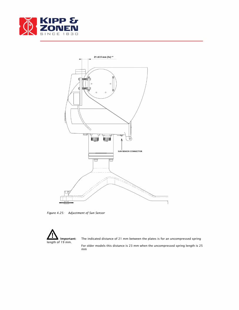
Figure 4.25: Adjustment of Sun Sensor
Important: The indicated distance of 21 mm between the plates is for an uncompressed spring length of 19 mm.
For older models this distance is 23 mm when the uncompressed spring length is 25 mm

Unscrew the cap from the sun sensor connector on the underside of the SOLYS 2 and connect the sensor connector. Before inserting the cable please check if the CHP 1 is perfectly aligned and the m8 bolts are secured!
When the sun sensor is connected for the first time, the tracker will reset (go to its home position) and return and starts using the sun sensor. Now its needs to be aligned. (See chapter 4.6.1)
4.6.1 ALIGNMENT OF SUN SENSOR This section applies only if you have purchased the optional Sun Sensor to operate in conjunction with the SOLYS 2. It is advised to have the SOLYS correctly tracking the sun before adjusting the sun sensor. The sun sensor can only be aligned when the direct radiation is above 300 W/m2. This can be checked by the status LED. When the sun sensor is connected and the status LED is green the radiation is above 300 W/m2, when blinking the radiation is too low to align the sun sensor. Once the sun sensor is connected and the direct radiation is above the 300 W/m2 it will correct the tracker position. The initial position of the sun sensor as indicated in figure 4.25 should be 23 mm (25 mm for old models) from the Pyrheliometer mounting clamp. This initial adjustment is important; otherwise the sun sensor is too far off to find the sun. When enough sun is present the sun sensor can be fine-tuned. The correct position can be obtained from the alignment target of the Pyrheliometer. If no Pyrheliometer is present the alignment target of the two mounting brackets can be used. Both brackets have a hole and the light beam falling through the first hole should make a circle just around the second hole. The information from the sun sensor is updated every 10 seconds, so after a changed alignment this interval should be waited before the new position is affected. Of course when the green status LED starts blinking no further adjustments are possible because the direct radiation is too low. The position of the sun sensor has to be adjusted using the 3 screws that hold the sun sensor in place. It is best to start adjusting one of the screws half a turn to see the effect. If the sunspot moves further away from the target, the direction of rotation should be reversed. Every time wait 10 seconds for the SOLYS 2 to update its position according to the new sun sensor angle. Adjust all three sun sensor screws until the alignment target is exactly positioned at the sun. When the sun senor is disconnected the SOLYS 2 has to recalculate its position and will first move to the home position before starting tracking again. When reconnected the sun sensor information will be used directly (after 10 seconds) when the status LED is constantly green. The position information from the sun sensor is not stored because the misalignment can be different for different positions (different times of the day). The sun senor will start every day with active tracking when the direct radiation is above the 300 W/m2
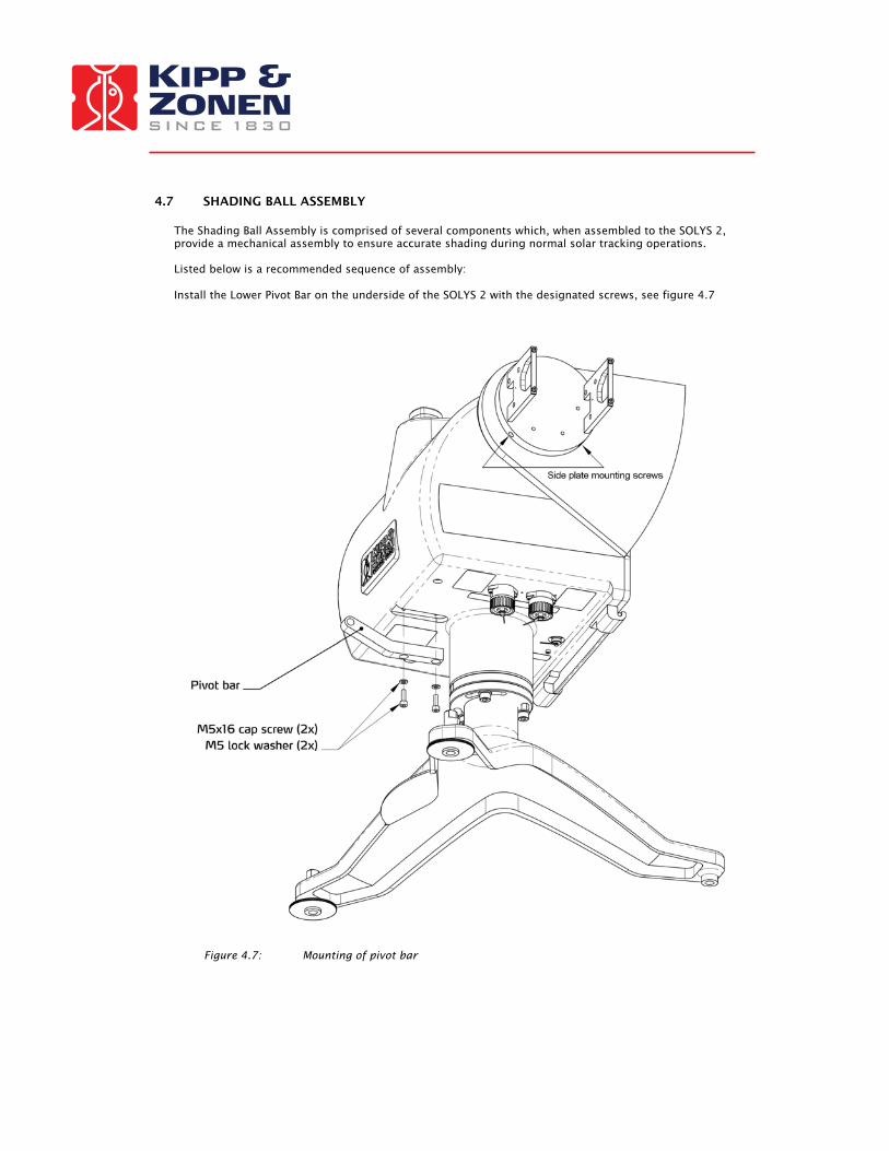
4.7 SHADING BALL ASSEMBLY The Shading Ball Assembly is comprised of several components which, when assembled to the SOLYS 2, provide a mechanical assembly to ensure accurate shading during normal solar tracking operations. Listed below is a recommended sequence of assembly: Install the Lower Pivot Bar on the underside of the SOLYS 2 with the designated screws, see figure 4.7
Figure 4.7: Mounting of pivot bar
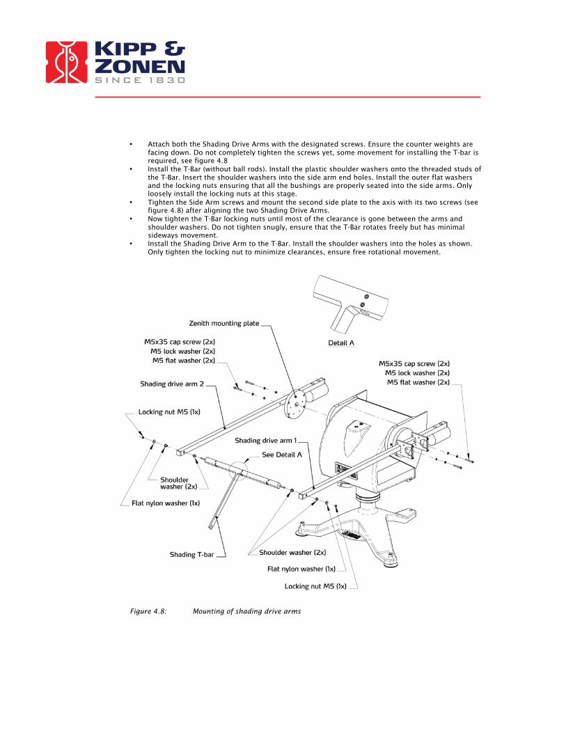
• Attach both the Shading Drive Arms with the designated screws. Ensure the counter weights are facing down. Do not completely tighten the screws yet, some movement for installing the T-bar is required, see figure 4.8
• Install the T-Bar (without ball rods). Install the plastic shoulder washers onto the threaded studs of the T-Bar. Insert the shoulder washers into the side arm end holes. Install the outer flat washers and the locking nuts ensuring that all the bushings are properly seated into the side arms. Only loosely install the locking nuts at this stage.
• Tighten the Side Arm screws and mount the second side plate to the axis with its two screws (see figure 4.8) after aligning the two Shading Drive Arms.
• Now tighten the T-Bar locking nuts until most of the clearance is gone between the arms and shoulder washers. Do not tighten snugly, ensure that the T-Bar rotates freely but has minimal sideways movement.
• Install the Shading Drive Arm to the T-Bar. Install the shoulder washers into the holes as shown. Only tighten the locking nut to minimize clearances, ensure free rotational movement.
Figure 4.8: Mounting of shading drive arms

• Install the the Shading support Arm to the T-Bar and Shading Pivot Bar hole with the nylon washers and locking nut shown in figure 4.9 and 4.10 Only tighten the locking nut to minimize clearances, ensure free rotational movement.
Figure 4.9: Mounting of shading support arm top part

Figure 4.10: Mounting of shading support arm lower part
Important: To verify that the Shading Assembly will not interfere with any obstructions, move the shading ball assembly down and rotate the SOLYS 2 by hand over its entire mechanical range. (With power off)
In a later firmware version a rotation lap is added in the firmware that will check this for you automatically after powering-up the SOLYS 2. (This will also check if the cable length of all instruments is sufficient)

4.8 TOP MOUNTING PLATE ASSEMBLY Figure 4.11 indicates how to mount the top mounting plate.
Figure 4.11 Mounting the Top Mounting Plate

4.9 MOUNTING KIPP RADIOMETERS WITHOUT VENTILATION UNIT Figure 4.15 indicates the mounting holes in detail for mounting up to three Kipp radiometers
Figure 4.15: Kipp & Zonen radiometers mounting holes without Ventilation unit (CVF 3)
Figure 4.19 Kipp & Zonen Pyranometer Installation Diagram.
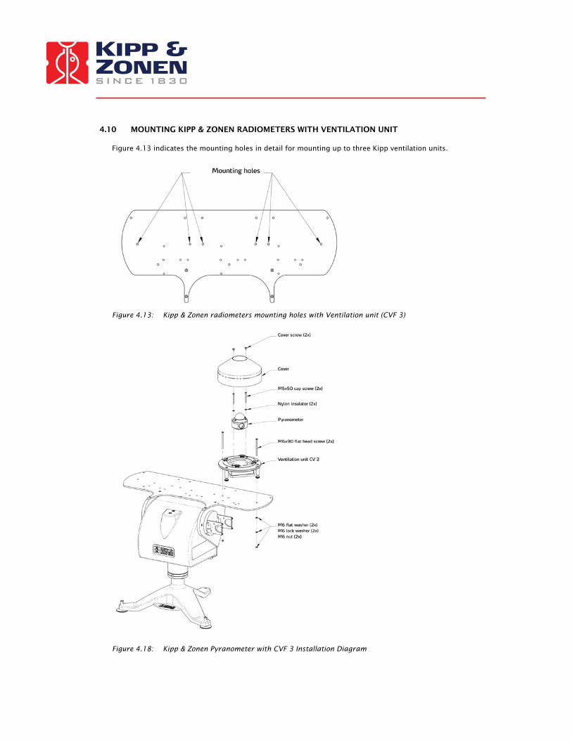
4.10 MOUNTING KIPP & ZONEN RADIOMETERS WITH VENTILATION UNIT Figure 4.13 indicates the mounting holes in detail for mounting up to three Kipp ventilation units.
Figure 4.13: Kipp & Zonen radiometers mounting holes with Ventilation unit (CVF 3)
Figure 4.18: Kipp & Zonen Pyranometer with CVF 3 Installation Diagram
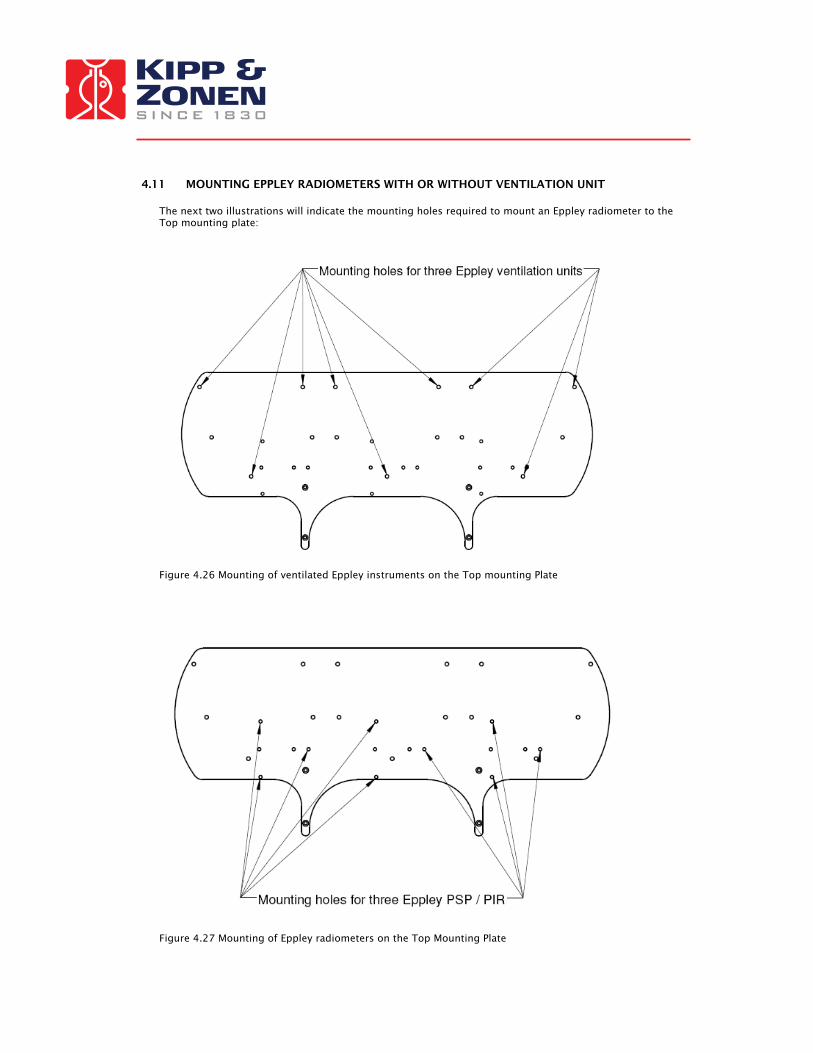
4.11 MOUNTING EPPLEY RADIOMETERS WITH OR WITHOUT VENTILATION UNIT The next two illustrations will indicate the mounting holes required to mount an Eppley radiometer to the Top mounting plate:
Figure 4.26 Mounting of ventilated Eppley instruments on the Top mounting Plate
Figure 4.27 Mounting of Eppley radiometers on the Top Mounting Plate
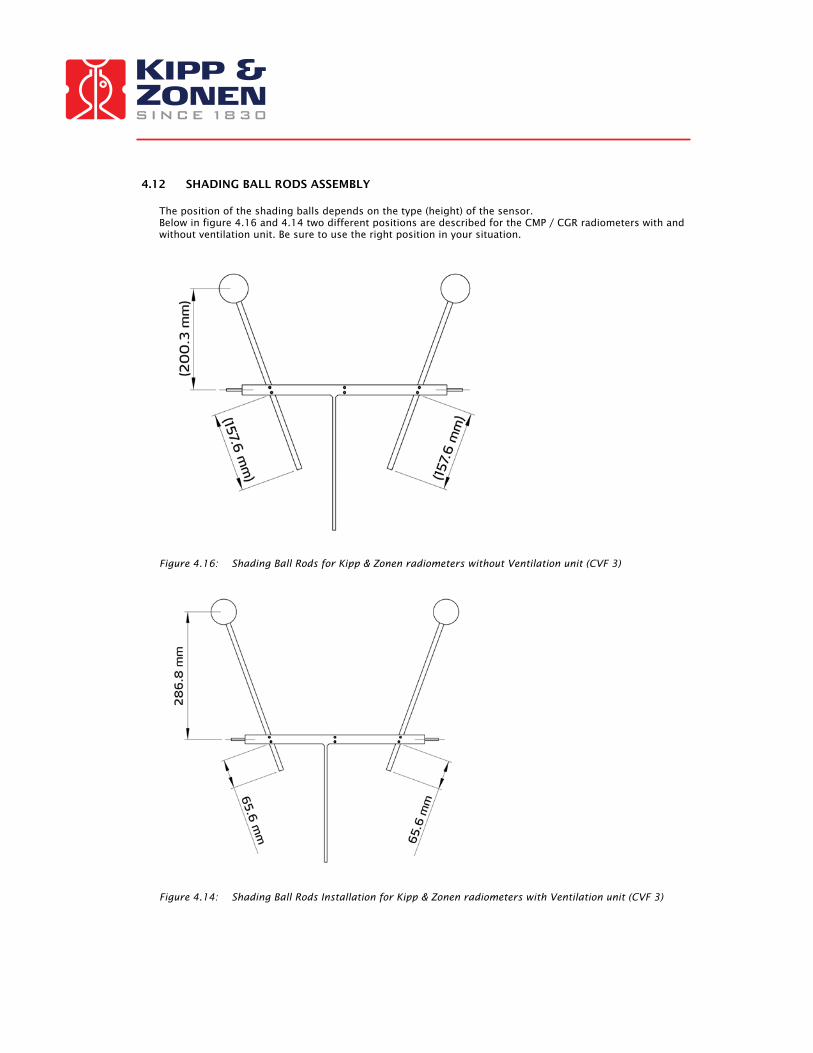
4.12 SHADING BALL RODS ASSEMBLY The position of the shading balls depends on the type (height) of the sensor. Below in figure 4.16 and 4.14 two different positions are described for the CMP / CGR radiometers with and without ventilation unit. Be sure to use the right position in your situation.
Figure 4.16: Shading Ball Rods for Kipp & Zonen radiometers without Ventilation unit (CVF 3)
Figure 4.14: Shading Ball Rods Installation for Kipp & Zonen radiometers with Ventilation unit (CVF 3)

Install the Shading Ball Rods by sliding them into the designated holes. See figure 4.12 for preliminary positioning of the Ball Rods in the T-Bar. Fine-tuning of the Ball Rods must be done later in the installation after the Verification of Levelling Procedure. DO NOT OVER-TIGHTEN the locking screws, it would make fine-tuning adjustments difficult later in the procedure.
Figure 4.12: Mounting of shading ball rods
Important: It’s important for the detector of the instrument to be fully shaded. This can be helpful during installation of third party radiometers. Tip: At this time fine adjust the Shading Ball Rods (of the optional Pointing & Shading Ball Assembly)
such that the Balls cast shadows onto the centres of the sensing elements of the radiometer on the Top Mounting Plate.
Important: Check that all unused connectors on the bottom of the SOLYS 2 have their caps installed during
normal operation. The Ethernet connection has a loose gray cap. Both power connections and the sun sensor have attached caps that should be closed when not in use.

5 EXTRA ACCESSORIES
Kipp & Zonen always anticipates in what the market needs. Here some additional accessories that need less explanation, but can ordered for your specific needs.
5.1 TILTED PYRANOMETER MOUNTING KIT TARGETING THE PV MARKET
Figure 5.1: Tilted Pyranometer mounting kit

5.2 SMALL TOP MOUNTING PLATE FOR INSTALLING A SINGLE KIPP & ZONEN RADIOMETER.
Figure 5.2: Small top mounting plate
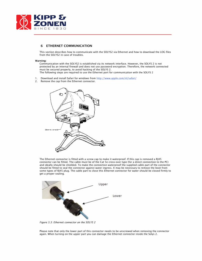
6 ETHERNET COMMUNICATION
This section describes how to communicate with the SOLYS2 via Ethernet and how to download the LOG files from the SOLYS2 in case of troubles.
Warning: Communication with the SOLYS2 is established via its network interface. However, the SOLYS 2 is not protected by an internal firewall and does not use password encryption. Therefore, the network connected must be secured properly, to avoid hacking of the SOLYS 2. The following steps are required to use the Ethernet port for communication with the SOLYS 2
1. Download and install Safari for windows from http://www.apple.com/nl/safari/ 2. Remove the cap from the Ethernet connector.
The Ethernet connector is fitted with a screw cap to make it waterproof. If this cap is removed a RJ45 connector can be fitted. The cable must be of the Cat 5e cross-over type (for a direct connection to the PC) and ideally should be shielded. To make the connection waterproof the supplied cable part of the connector should be fitted to seal the connector against water ingress. It may be necessary to remove the boot from some types of RJ45 plug. The cable part to close this Ethernet connector for water should be closed firmly to get a proper sealing.
Figure 3.3: Ethernet connector on the SOLYS 2 Please note that only the lower part of this connector needs to be unscrewed when removing the connector again. When turning on the upper part you can damage the Ethernet connector inside the Solys 2.
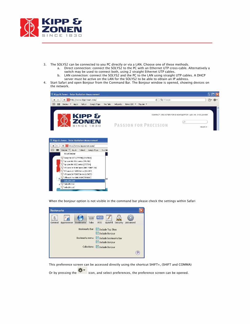
3. The SOLYS2 can be connected to you PC directly or via a LAN. Choose one of these methods.
a. Direct connection: connect the SOLYS2 to the PC with an Ethernet UTP cross-cable. Alternatively a switch may be used to connect both, using 2 straight Ethernet UTP cables.
b. LAN connection: connect the SOLYS2 and the PC to the LAN using straight UTP cables. A DHCP server must be active on the LAN for the SOLYS2 to be able to obtain an IP address.
4. Start Safari and open Bonjour from the Command Bar. The Bonjour window is opened, showing devices on the network.
When the bonjour option is not visible in the command bar please check the settings within Safari
This preference screen can be accessed directly using the shortcut SHIFT+, (SHIFT and COMMA)
Or by pressing the icon, and select preferences, the preference screen can be opened.

5. Click SOLYS2<serial> in the Bonjour window and enter username user and password solys upon request. Note that in case of a direct connection, Windows needs a few minutes to assign itself an Automatic Private IP Address. If it does not, verify that Automatic Private IP Address of the TCP/IP properties of the PC’s network connection is enabled.
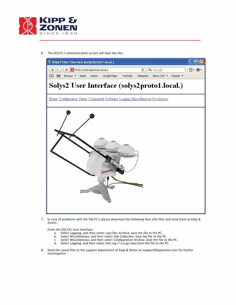
6. The SOLYS 2 communication screen will look like this:
7. In case of problems with the SOLYS 2 please download the following four LOG files and send them to Kipp & Zonen. From the SOLYS2 User Interface:
a. Select Logging, and then select Log Files Archive. Save the file to the PC. b. Select Miscellaneous, and then select Info Collection. Save the file to the PC. c. Select Miscellaneous, and then select Configuration Archive. Save the file to the PC. d. Select Logging, and then select Sun Log (*.csv.gz.new) Save the file to the PC.
8. Send the saved files to the support department of Kipp & Zonen at [email protected] for further
investigation.
6.1 EXTERNAL COMMANDS The following list of commands is available when connected to the SOLYS 2 More information is available in the SOLYS 2 user interface. (Web browser) -Low level command This enables to enter any command (two letters) without actually scrolling down the entire list of command to search for the correct one. This is normally used for experienced users. Behind every next command in this document we will provide the two letter command that can be entered in the low level command line. -Accessory (AC) This feature will tell you the presence of any accessory instruments (like a sun sensor) -Adjust (AD) This will enables to retrieve or set adjustments for the azimuth- and zenith motors. -Maximum Acceleration (AM) This will enables to retrieve or set maximum operating acceleration for the azimuth- and zenith motors. -Baudrate (BA) This will enables to retrieve or set the baud rate for communication with the controller. -Startup time (BE) To retrieve the time at which the most recent session (reset) began. -Checkout time (CH) With this function you can actually set the SOLYS 2 in sleep mode (and home position) for a desired period. -Clear (CL) Instantly stops all motors. -Cold start (CO) Resets the entire configuration to default and will reboot the SOLYS2 -Current position (CP) Retrieves the current positions of all motors. -Current time and positions (CT) Retrieves the current time and positions of all motors -Error correction (EC) To retrieve or set the error correction to be enabled (1) or disabled (0) -Function (FU) To retrieve or set the actual mode of the SOLYS 2 -active tracking mode , tracking the sun using a sun sensor for corrections -sun tracking mode, tracking the sun & daily time adjustments -no function, SOLYS 2 will not move -Standard operation mode, positioning mode to manually point the sun tracker to a random point using PO commands. -Standard operation (reverse) mode , positioning mode to manually point the sun tracker to a random point using PO commands. -Home (HO) Tells the SOLYS 2 to go to its home position. (It will stay there for over 1 minute) -Checkout at home (HH) To put the SOLYS 2 in sleep mode after it’s returned to its home position -Instrument status (IS) To retrieve the current status (mode) of the SOLYS 2. -Lockout GPS altitude (LA) To retrieve or set enabling of updates to the configuration due to GPS altitude changes (1= updates enabled)

(0= updates disabled) -Location and pressure (LL) To retrieve or set the latitude, longitude and nominal atmospheric pressure recorded for the site. -Lockout GPS position (LP) To retrieve or set enabling of updates to the configuration due to GPS position (longitude, latitude) changes. (1= updates enabled) (0= updates disabled) -Move (MO) Enables to send each motor (as quickly as possible) to its end position. -Motor Status (MS) To retrieve the status of each motor. (Should be successful) -No hard limits (NL) To retrieve or set the parameter for enabling the internal pot meters as a security device. -No soft limits (NX) To retrieve or set the parameter for enabling the internal Range settings (XT). -Origin (OR) To retrieve or set the Zero offset from the reference point (East is -90°) -Pause(PA) Enables to pause the actual tracking mode for a specified time. (Maximum ten hours) -Position (PO) To retrieve or set the final position for all motors -Power save (PS) To retrieve or set the power savings mode (1=enabled, 0=disabled) -Change protection (PW) Allows or disallows modification to be done by the web interface to the configuration. -Change password (PW) Most of the set commands desire a password which can be changed here. -Queue status (QS) To see the actual queue status. (Every positioning command (PO) is queued) -Restart sun tracking (RE) Enables to restart the sun tracking -Sun sensor scaling (SC) To retrieve or set the scaling factor for each sun sensor quadrant along with the nominal scaling of the sensor -Serial Number (SE) To retrieve the serial number of the SOLYS 2 -Sun Intensity (SI) Retrieves the current sun intensity -Sun speed (SP) To retrieve or set the current sun speed. It is the speed at which the solar algorithm runs -Sun sensing parameters (SS) To retrieve or set the amount of time over which each sun observation takes place and the intensity level below which the sun is deemed to be obscured. -Steps per revolution (ST) To retrieve or set, from permanent memory, the number of stepping units in a complete revolution for all motors

-Synchronize (SY) To put the SOLYS 2 in sleep mode in the current position after the last segment -Time (TI) To retrieve or set the internal time (Universal) -Tilt (TL) To retrieve or set the tilt induced latitude and longitude error of the tracker once it has been levelled -Track (TR) To schedule your own tracking orbit. -Version (VE) Just to indicate version information of the I/O board and application. -Maximum Velocity (VM) To retrieve or set the maximum operating velocity for all motors. -Warm reset (WA) Performs a reboot with current configuration. -Watchdog Expire (WD) Lets the watchdog expire and causes a reboot -Where (WH) To retrieves the end of path information for each specified motor -Watermark position (WP) To retrieve the watermark position of all motors. (The watermark position is the most recent position of the motor in which the reference sensor was not activated) -Range (XT) To retrieve or set the range for the instrument. (Azimuth and zenith)
6.2 INTERFACING WITH THRID PARTY APPLICATIONS
Creating script is possible to retrieve data from the SOLYS 2 via the Ethernet port TCP/IP 15000. The SOLYS2 sun tracking application has its communication interface on TCP port 15000. Note that it can only handle one connection at a time on this port. In case of a new connection request, the existing socket is disconnected. Note that the web interface of the SOLYS2 also uses this TCP port to control the sun tracking application. Therefore, do not use the web interface and direct communication to the TCP port at the same time. Also, do not communicate directly with multiple applications to the TCP port. This may lead to unexpected behavior. Commands, replies and checksum All commands listed on the Commands section of the web interface may be issued via the communication interface of the suntracking application. To ensure proper transfer of data, a checksum must be added to every command according the following algorithm (C code):

void AddCheckSum( unsigned char command[] ) { unsigned char checkSum = 0; unsigned char end = 0; /* calculate sum so far */ while ( command[ end ] ) { checkSum += command[ end ]; end++; } /* separate check bytes by a space */ checkSum += command[ end ] = ' '; end++; /* make all characters printable */ while ( checkSum < 130 || checksum > 223 ) { checkSum += command[ end ] = '^'; end++; } /* add printable checksum */ command[ end ] = 256 – checkSum; }
After every command, a reply is returned. A reply includes a checksum. To verify the reply, simply sum the binary representations of all printable characters. That sum must be zero (modulo 256). Some commands require a password (see PW command). The default password is 65535. Do not change the password. The web interface of the tracker relies on the fact that the password is 65535. Losing the password may lock you out of the tracker. Error Codes If an unrecognized command or a command with missing or incorrect parameters is received, the tracker will respond NO followed by one of the following error codes: · 1 framing error. · 2 reserved for future use. · 3 unrecognized command. · 4 message too long. · 5 unimplemented instruction or non decodable parameters. · 6 motion queue is full, movement command rejected. · 7 travel bounds exceeded. · 8 maximum velocity exceeded. · 9 maximum acceleration exceeded. · A instrument is operating autonomously, command rejected. · B invalid adjustment size. · C invalid total adjustment. · D duration out of range. · E reserved for future use. · F illegal extent specified. · G attempt to change password protected data. · Y hardware failure detected. · Z illegal internal firmware state.

7 MAINTENANCE
The SOLYS 2 itself does not need any maintenance. The following things can be checked on visiting intervals: - Periodically check the condition of all cables and connectors. - Check drying cartridges for mounted radiometers. - Check if bubble level still within range. - Check the sun sensor position. The SOLYS 2 itself does not need any re-calibration. However we suggest having the measuring instruments, used on the SOLYS 2, re-calibrated every two years

8 SOLVING PROBLEMS The SOLYS 2 is designed for long periods of operation with no operator maintenance. However, if a problem occurs that cannot be corrected by using the standard operating information supplied in the preceding sections of this manual, use the information in this chapter to identify and solve the problem. If the problem cannot be corrected after reviewing the information in the following section, contact Kipp & Zonen. When contacting Kipp & Zonen with technical assistance questions, ensure you have the following information available to aid the technician in solving your problem:
• The serial number of the SOLYS 2. This information is listed on the serial number label, located on the bottom of the unit.
• Mounted options • Problem description • Log files (see chapter 6)
If you cannot solve the problem by the tips on the next pages, email or fax the problem description to your nearest Kipp & Zonen facility, as listed on our website. Kipp & Zonen B.V. Tel: +31-15-2755210 P.O. Box 507, Fax: +31-15-262 0351 2600 AM Delft, E-mail: [email protected] The Netherlands Website: http://www.kippzonen.com
8.1 PROBLEM CHECK-LIST Check the items in the following list. If these do not help, see the following section on troubleshooting. Check that: - Power is supplied to the unit. Power / Temperature LED should be on and green. In case the power LED is red and running on AC power, it can take up to 30 minutes before the SOLYS 2 interior is above – 20ºC - In case power LED is red and running on DC power, the SOLYS will only start when environmental
temperature gets above -20ºC. - GPS reception is possible; the GPS antenna should not be obstructed by instruments or near by objects.
(status LED should be green) The SOLYS 2 does not follow the sun properly, what can be wrong? Sun sensor connected but not adjusted? Check bubble level if the bubble is still in the ring. - Is alignment target (from Pyrheliometer or mounting clamps) correctly pointing at the sun?

8.2 FAQ Q: I have a problem with the aligning the SOLYS A: Proper placement of the SOLYS 2 is important when installing it, as it requires a specific amount of free
space to operate.
Make sure the tripod is placed on a solid base. Keep in mind that final alignment is only possible when the sun is shining. The following 8 steps are required to align the SOLYS 2. in the previous paragraphs additional information is available for each step.
1. Position the tripod with the K&Z logo pointing East. 2. Put the SOLYS 2 on the tripod with the E-marking on the bottom flange pointing East. 3. Put the M8 bolts in by hand but do not tighten them yet. 4. Level the SOLYS by adjusting the tripod feet and checking the bubble level. 5. Connect power to the SOLYS 2 and let it move to its home position. 6. Wait until the green status light is on to indicate the correct GPS position is received.
The SOLYS 2 will now rotate to the sun position. 7. Rotate the SOLYS on its tripod (adjust azimuth) until the alignment target from the bracket points
exactly at the sun. 8. Fasten the M8 bolts 9. The side mounting plate is adjusted in the factory and need no adjustment. 10. If the side mounting plates have been loosened or removed adjust the zenith position as well until
the alignment target points at the sun and fasten the screws in the side mounting plates. Q: It seems we can move the tracker by hand. Is this allowed? A: Moving the SOLYS by hand or blocking it, when powered is enabled, can DAMAGE the belt drive! When doing this please consider the following: -Power should be disconnected
-Turning should be done very slowly -Turning should be done using minimum amount of force.
Q: How to guide the cables and what is the advised cable legth. A: At initial start-up, the SOLYS 2 will make a 540 degree rotation lap. This is checking if the cable length
is sufficient. Chapter 15 has a drawing which indicates how to guide the cable.
Q: The Solys2 status LEDs are flashing a code that is not listed in the manual. The flashing sequence is red followed by green.A: The code may signify a disagreement between the Solys2 GPS and the sun sensor. This can be caused by a misalignment of the side mounting plate. Contact your local Kipp & Zonen distributor for further details.

9 SOFTWARE OVERVIEW The software used in the SOLYS 2 contains open source components that are listed in the table below. This software is available from our website: www.kippzonen.com/suntrackers/SOLYS2/software/download The software and versions listed below were used during the production of this manual. Look on the website for the last revision of this list. Software Version License Apache httpd-2.2.8 Apache License 2.0 Avahi avahi-0.6.17 LGPL 2.1 BusyBox busybox-1.1.3 GPL 2 Expat XML parser expat-2.0.0 EXPAT License GNU C Library glibc-2.3.3 LGPL 2.1 / Licenses for non-FSF code in
GLIBC GNU Project Debugger gdb-6.5 GPL 2 GPS Daemon gpsd-4093 (pre 2.34
+ patches) GPSD License
Grand Unified Bootloader grub-0.97-33 GPL 2 Ifplugd ifplugd-0.28 GPL 2 Libdaemon libdaemon-0.10 LGPL 2.1 Linux Kernel linux-2.4.31 GPL 2 LinuxThreads Library glibc-linuxthreads-
2.3.3 LGPL 2
Ncurses Library ncurses-5.5 NCURSES License Network Time Protocol Daemon
ntp-4.2.2p3-RC NTP License
OpenSSL (for configuration data integrity only)
openssl-0.9.8c OpenSSL License / SSLeay License
PHP php-5.2.5 PHP 3.01 License RT-Linux rtlinux-3.1 OPEN RTLINUX PATENT LICENSE / GPL 2 SOLYS2 Suntracking Tools
V1R1 Kipp & Zonen SOLYS License
uClibc uClibc-0.9.28.3 LGPL 2 Vortex86 watchdog driver vx86wdt GPL 2 Watchdog Daemon watchdog-5.4 GPL 1
Table 7.1
9.1 ALGORITHM The algorithm the SOLYS 2 is using is a free to use algorithm developed by J.J. Michalsky. (Working for N.O.A.A.) One of the inputs for this algorithm is time! Six out of ten years the time needs to be corrected due to the earth slowing down. This is what we call the “leap second” The SOLYS 2 has a built in GPS receiver that constantly synchronizes the internal clock with the satellite clock (compensating for drift in the RTC (real time clock) as for the equation of time, the correction is also applied into this algorithm.
10 FIRMWARE Kipp & Zonen is always looking for implementing improvements by changing the hardware or firmware. It’s advised to check our website on a regular base for the latest version of the firmware. It can easily be upgraded using the network connection available on the SOLYS 2. We strongly advise to perform these updates even when your SOLYS 2 seems to operate correct. It can prevent any unwanted situations in the future. To download the latest firmware update, please check the following webpage: http://www.kippzonen.com/?product/2021/SOLYS+2.aspx V1.2 initial release V1.5 released October 2009 V1.7 released August 2010 The current version can be checked using a laptop (see chapter 6)
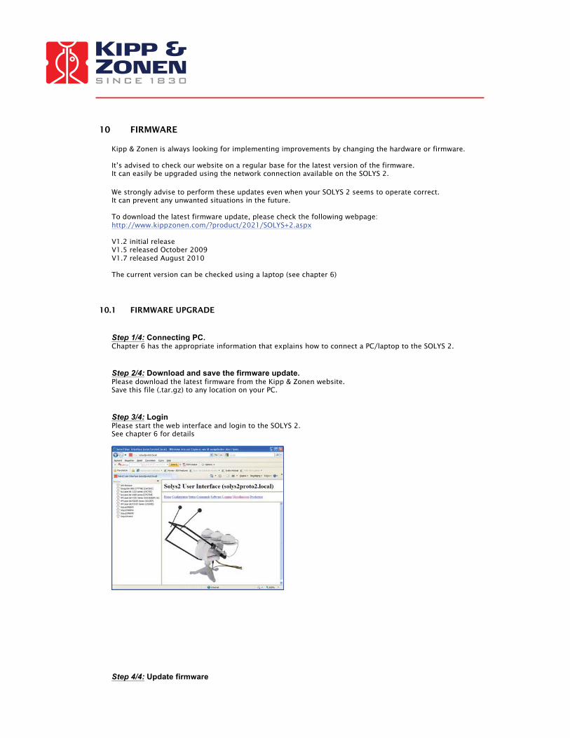
10.1 FIRMWARE UPGRADE Step 1/4: Connecting PC. Chapter 6 has the appropriate information that explains how to connect a PC/laptop to the SOLYS 2. Step 2/4: Download and save the firmware update. Please download the latest firmware from the Kipp & Zonen website. Save this file (.tar.gz) to any location on your PC. Step 3/4: Login Please start the web interface and login to the SOLYS 2. See chapter 6 for details
Step 4/4: Update firmware
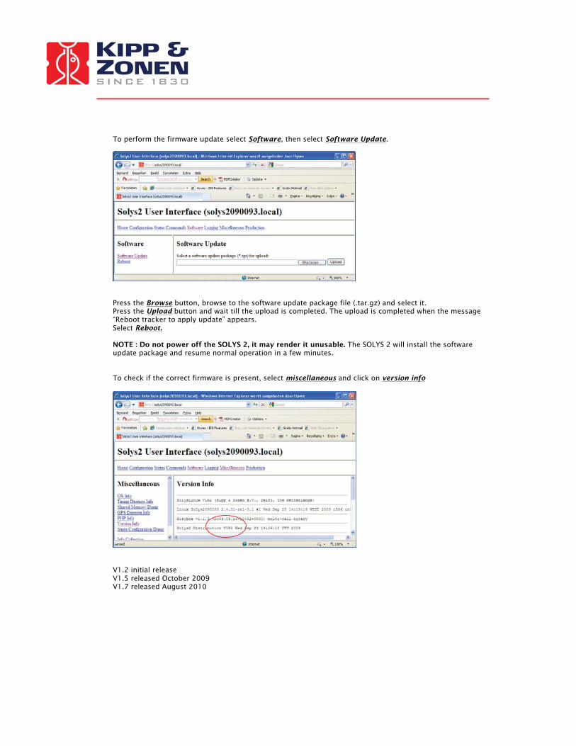
To perform the firmware update select Software, then select Software Update.
Press the Browse button, browse to the software update package file (.tar.gz) and select it. Press the Upload button and wait till the upload is completed. The upload is completed when the message “Reboot tracker to apply update” appears. Select Reboot. NOTE : Do not power off the SOLYS 2, it may render it unusable. The SOLYS 2 will install the software update package and resume normal operation in a few minutes. To check if the correct firmware is present, select miscellaneous and click on version info
V1.2 initial release V1.5 released October 2009 V1.7 released August 2010

11 DRAWING SIDE MOUNTING PLATE When optional components or instruments need to be installed on the side of the SOLYS 2, an additional side mounting plate is required. The next illustration is the mechanical drawing of the side mounting plate. This information is required to create mounting materials for optional components or instruments.

12 DRAWING LARGE TOP MOUNTING PLATE The Shading assembly is equipped with the top mounting plate. If a top mounting plate is required without shading assembly it can be ordered separately The Part number for the top mounting plate is 0367709. It might be necessary to adjust the large top mounting plate for suiting specific instruments. The next illustration is the mechanical drawing of the large top mounting plate. There is also a smaller version available to suit one Pyranometer The part number for the small top mounting plate is 0367712.

13 HEIGHT SPECIFICATIONS SOLYS 2 INCLUDING INSTRUMENTS The next illustration is displaying the actual height of the instruments.

14 PARTNUMBERS SHADING ASSEMBLY The next illustration shows the part numbers for each of the separate components from the shading assembly in case a part is broken or damaged.
� An extra rod/ball can be purchased

15 HOW TO GUIDE THE CABLES The next illustration shows the best way to guide all your cables. It’s strongly advised to have the proper cable length as indicated below, so that the SOLYS 2 can move freely throughout the entire year. As a security check, the SOLYS 2 will make a 540 degree rotation lap at initial power up.
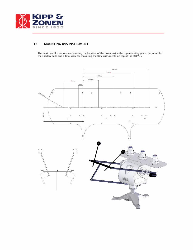
16 MOUNTING UVS INSTRUMENT The next two illustrations are showing the location of the holes inside the top mounting plate, the setup for the shadow balls and a total view for mounting the UVS instruments on top of the SOLYS 2

Passion for Precision
Go to www.kippzonen.com for your local distributor or contact your local sales office
HEAD OFFICE
Kipp & Zonen B.V.Delftechpark 36, 2628 XH DelftP.O. Box 507, 2600 AM DelftThe Netherlands
T: +31 (0) 15 2755 210F: +31 (0) 15 2620 [email protected]
Kipp & Zonen Asia Pacific Pte. Ltd.81 Clemenceau Avenue#04-15/16 UE SquareSingapore 239917
T: +65 (0) 6735 5033F: +65 (0) 6735 [email protected]
Kipp & Zonen USA Inc.125 Wilbur PlaceBohemiaNY 11716United States of America
T: +1 (0) 631 589 2065F: +1 (0) 631 589 [email protected]
Kipp & Zonen France S.A.R.L.7 Avenue Clément AderZA Ponroy - Bâtiment M94420 Le Plessis TréviseFrance
T: +33 (0) 1 49 62 41 04F: +33 (0) 1 49 62 41 [email protected]
SALES OFFICES
Our customer support remains at your disposal for any maintenance or repair, calibration, supplies and spares.
Für Servicearbeiten und Kalibrierung, Verbrauchsmaterial und Ersatzteile steht Ihnen unsere Customer Support Abteilung zur Verfügung.
Notre service ‘Support Clientèle’ reste à votre entière disposition pour tout problème de maintenance, réparation ou d’étalonnage ainsi que pour les accessoires et pièces de rechange.
Nuestro servicio de atención al cliente esta a su disposición para cualquier actuación de mantenimiento, reparación, calibración y suministro de repuestos.