
Solving Manufacturing Problems
41
13Dec2016 Ronald M. Shewchuk Solving Manufacturing Problems 1. 8D Problem Solving Methodology 2. Containment 3. Defect Characterization 4. Failure Analysis 5. Defect Characterization Case Study 6. Root Cause Analysis Methodology 7. Prioritizing Corrective Actions 8. Validate that Corrective Actions Prevent Problem Recurrence 9. Leverage Countermeasures to Similar Products and/or Processes 10. Root Cause Analysis Case Study 11. References 12. Internet Resources
-
Upload
ronald-shewchuk -
Category
Engineering
-
view
505 -
download
2
Transcript of Solving Manufacturing Problems
13Dec2016 Ronald M. Shewchuk
Solving Manufacturing Problems1. 8D Problem Solving Methodology
2. Containment
3. Defect Characterization
4. Failure Analysis
5. Defect Characterization Case Study
6. Root Cause Analysis Methodology
7. Prioritizing Corrective Actions
8. Validate that Corrective Actions Prevent Problem Recurrence
9. Leverage Countermeasures to Similar Products and/or Processes
10. Root Cause Analysis Case Study
11. References
12. Internet Resources
13Dec2016 Ronald M. Shewchuk
Problem Solving Approach – 8D
• The Ford Motor Company developed the 8D (8 Disciplines) Problem Solving
Process
• Ford created the 8D Process to help teams deal with quality control and safety
issues; develop customized, permanent solutions to problems; and prevent problems
from recurring
• First published it in their 1987 manual, Team Oriented Problem Solving (TOPS)
• In the mid-90s, Ford added an additional discipline, D0: Plan
• The process is now Ford's global standard, and is called Global 8D
• Although the 8D Process was initially applied in the manufacturing, engineering,
and aerospace industries, it is useful and relevant in any industry.
13Dec2016 Ronald M. Shewchuk
8D Problem Solving Methodology
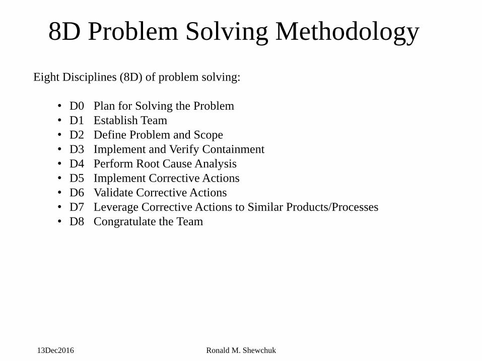
Eight Disciplines (8D) of problem solving:
• D0 Plan for Solving the Problem
• D1 Establish Team
• D2 Define Problem and Scope
• D3 Implement and Verify Containment
• D4 Perform Root Cause Analysis
• D5 Implement Corrective Actions
• D6 Validate Corrective Actions
• D7 Leverage Corrective Actions to Similar Products/Processes
• D8 Congratulate the Team
13Dec2016 Ronald M. Shewchuk
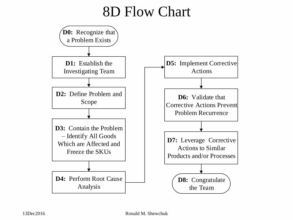
8D Flow Chart
D0: Recognize that
a Problem Exists
D1: Establish the
Investigating Team
D3: Contain the Problem
– Identify All Goods
Which are Affected and
Freeze the SKUs
D4: Perform Root Cause
Analysis
D7: Leverage Corrective
Actions to Similar
Products and/or Processes
D6: Validate that
Corrective Actions Prevent
Problem Recurrence
D5: Implement Corrective
Actions
D8: Congratulate
the Team
D2: Define Problem and
Scope
13Dec2016 Ronald M. Shewchuk 5
Root Cause Analysis
13Dec2016 Ronald M. Shewchuk 6
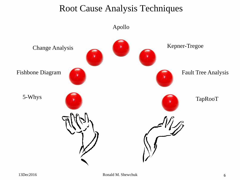
Root Cause Analysis Techniques
5-Whys
Fishbone Diagram
Change Analysis
Fault Tree Analysis
TapRooT
Kepner-Tregoe
Apollo
13Dec2016 Ronald M. Shewchuk 7
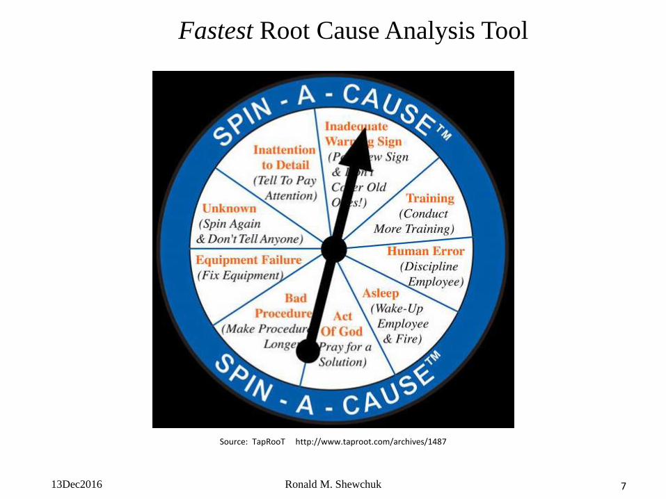
Fastest Root Cause Analysis Tool
Source: TapRooT http://www.taproot.com/archives/1487
13Dec2016 Ronald M. Shewchuk 8
• A powerful technique for increasing equipment reliability is to
understand the failure modes of your critical equipment through
Root Cause Analysis (RCA)
• Root Cause Analysis is like a crime scene investigation
• It consists of asking the right questions and performing the right
analyses to drill down to the root cause of component failure
• Once the root cause has been isolated a countermeasure can be
implemented which could include one or more of the following.
1) Modification of component operating parameters
2) Installation of component monitoring sensors & alarms
3) Modification of equipment operation check sheets
4) Installation of component shielding
Root Cause Analysis
13Dec2016 Ronald M. Shewchuk 9
Root Cause Analysis
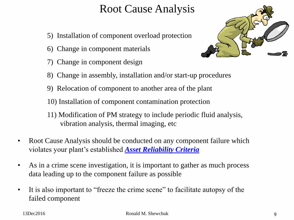
5) Installation of component overload protection
6) Change in component materials
7) Change in component design
8) Change in assembly, installation and/or start-up procedures
9) Relocation of component to another area of the plant
10) Installation of component contamination protection
11) Modification of PM strategy to include periodic fluid analysis,
vibration analysis, thermal imaging, etc
• Root Cause Analysis should be conducted on any component failure which
violates your plant’s established Asset Reliability Criteria
• As in a crime scene investigation, it is important to gather as much process
data leading up to the component failure as possible
• It is also important to “freeze the crime scene” to facilitate autopsy of the
failed component
13Dec2016 Ronald M. Shewchuk 10
• The most critical step of Root Cause Analysis is
Defect Characterization / Failure Analysis
• If this step is not properly executed your team will be chasing butterflies in the
night
Root Cause Analysis
13Dec2016 Ronald M. Shewchuk 11
• You cannot defeat your enemy until you intimately know your enemy
• Otherwise you don’t know what you are fighting and your Root Cause
Analysis will be led down the wrong garden path
• Defect characterization allows you to gain this knowledge systematically
• Characterization describes and quantifies the size, shape, depth, location,
color, frequency of occurrence, etc of the defect in order to point to the cause
of the defect
• This extends to the microscopic level including chemical identification of
foreign matter
• Let us consider the case of a metal part subassembly to understand the defect
characterization process
Defect Characterization
13Dec2016 Ronald M. Shewchuk 12
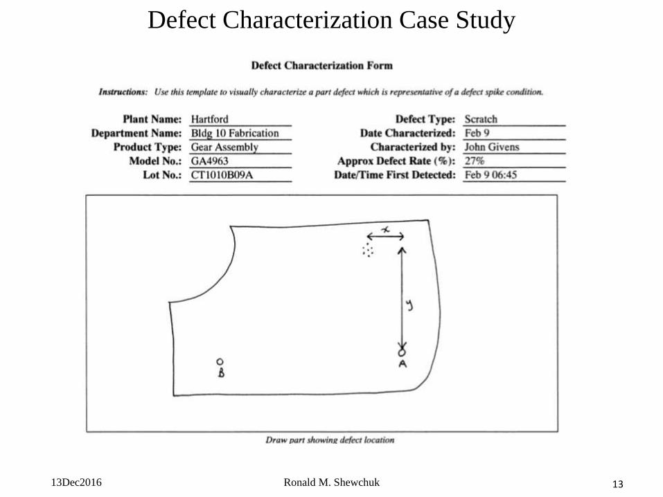
GA4963 Scratch Defect
The morning production meeting at ABC Molding has just begun. The safety review and customer
satisfaction review have been completed without issue. John Givens, the day shift production supervisor,
now mentions a scratch defect that is occurring on the front face of the GA4963 gear assembly currently
in production. The GA4963 gear assembly is a unique assembly manufactured for Precision Motor Co.
Most gear assemblies have a plastic housing but the GA4963 housing is made of polished 316 stainless
steel. Precision Motor uses this gear assembly within their premier product line and exterior scratches are
unacceptable. John mentions some possible areas where the scratch could be coming from but indicates
that his crew has not yet found the source of the scratch. Joe Spaulding, the 20 ton stamping press
operator, volunteered that it could be the press since the defect is repeating in the same location. Henry
James, the warehouse manager, countered this idea by mentioning that he thought he saw scratches on the
316 SS sheet stock. Soon, other members of the production meeting are providing their ideas on possible
sources of the scratches.
Frank Anderson, the production superintendent, who is typically a soft-spoken man unless he is speaking
about his beloved Tennessee Titans, capitalizes on a lull in the discussion to intervene “You all are talking
about this defect as if it were a phantom, with phantom causes. But I don’t see that an example part with
this defect has been brought into this room and I don’t see that a Defect Characterization Form has been
completed for this issue. Let’s grab a few parts from the production line and characterize this defect
together.”
Defect Characterization Case Study
13Dec2016 Ronald M. Shewchuk 13
Defect Characterization Case Study
13Dec2016 Ronald M. Shewchuk 14
Defect Characterization Case Study
13Dec2016 Ronald M. Shewchuk 15
Defect Characterization Case Study
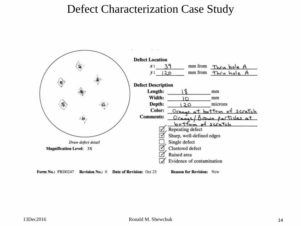
The drawing was not a work of art. It didn’t need to be. It merely needed to serve as a communication
tool. Drawings, sketches, diagrams are the universal language. As the defect characterization form was
projected on the screen Tim Westlake, the maintenance manager, commented “Wait a minute … I have
seen that hexagonal pattern before. It looks like the base metal on the gripper pads on the pick and place.
We had to replace the air cylinder last week.”
As it turned out, the air cylinder pressure on the pick and place was set too high causing the rubber gripper
pads to wear out exposing the bare case-hardened steel base. This was the source of the scratches. This
simple example demonstrates the importance of characterizing defects to identify root causes. If, for
example, the hexagonal pattern of the gripper base was not known, analysis of the particulates at the
bottom of the scratches might have pointed to the deteriorating rubber gripper pads. Today, we have a
multitude of instrument analysis techniques available which can be used to characterize both inorganic
and organic contaminants.
13Dec2016 Ronald M. Shewchuk 16
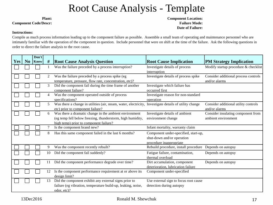
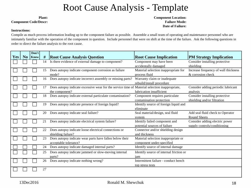
• The Root Cause Analysis Template on the next slide includes a
collection of typical questions to ask with implications to root
cause and ultimately, your PM strategy
• The relevant questions depend on the type of component which has
failed and the failure mode, thus, blanks have been added for your
team to add more specific RCA questions
• The size of the RCA Team depends on the scope of the failure incident
• If it is a simple component failure with limited scope the RCA team could consist
of just one person
• If personnel safety or the environment were compromised, or there was significant
economic impact from the failure incident the RCA team would consist of
representatives from key departments
Root Cause Analysis
13Dec2016 Ronald M. Shewchuk 17
Root Cause Analysis - TemplatePlant: Component Location:
Component Code/Descr: Failure Mode:
Date of Failure:
Instructions:
Yes NoDon't
Know # Root Cause Analysis Question Root Cause Implication PM Strategy Implication
1 Was the failure preceded by a process interruption? Investigate details of process
interruption
Modify startup procedure & checklist
2 Was the failure preceded by a process spike (eg
temperature, pressure, flow rate, concentration, etc)?
Investigate details of process spike Consider additional process controls
and/or alarms
3 Did the component fail during the time frame of another
component failure?
Investigate which failure has
occurred first
4 Was the component operated outside of process
specifications?
Investigate reason for non-standard
operation
5 Was there a change in utilities (air, steam, water, electricity,
etc) prior to component failure?
Investigate details of utility change Consider additional utility controls
and/or alarms
6 Was there a dramatic change in the ambient environment
(eg temp fell below freezing, thunderstorm, high humidity,
high temp) prior to component failure?
Investigate details of ambient
environment change
Consider insulating component from
ambient environment
7 Is the component brand new? Infant mortality, warranty claim
8 Has this same component failed in the last 6 months? Component under-specified, start-up,
shut-down and/or operation
procedure inappropriate9 Was the component recently rebuilt? Rebuild procedure, install procedure Depends on autopsy
10 Did the component fail suddenly? Fatigue failure, contamination,
thermal overload
Depends on autopsy
11 Did the component performance degrade over time? Dirt accumulation, component
deterioration, lubrication failure
Depends on autopsy
12 Is the component performance requirement at or above its
design limit?
Component under-specified
13 Did the component exhibit any external signs prior to
failure (eg vibration, temperature build-up, leaking, noise,
odor, etc)?
Use external sign to focus root cause
detection during autopsy
Compile as much process information leading up to the component failure as possible. Assemble a small team of operating and maintenance personnel who are
intimately familiar with the operation of the component in question. Include personnel that were on shift at the time of the failure. Ask the following questions in
order to direct the failure analysis to the root cause.
13Dec2016 Ronald M. Shewchuk 18
14 Is there evidence of external damage to component? Component may have been
accidentally damaged
Consider installing protective
shielding
15 Does autopsy indicate component corrosion as failure
mode?
Material selection inappropriate for
process fluid
Increase frequency of wall thickness
& corrosion check
16 Does autopsy indicate incorrect assembly or missing parts? Warranty claim or inadequate
rebuild/install procedure
17 Does autopsy indicate excessive wear for the service time of
the component?
Material selection inappropriate,
lubrication insufficient
Consider adding periodic lubricant
analysis
18 Does autopsy indicate external particulate contamination? Component requires particulate
contamination protection
Consider installing protective
shielding and/or filtration
19 Does autopsy indicate presence of foreign liquid? Identify source of foreign liquid and
eliminate
20 Does autopsy indicate seal failure? Seal material/design, seal fluid
system
Add seal fluid check to Operator
Round Sheets
21 Does autopsy indicate electrical system failure? Identify failed component and
potential sources of failure
Consider adding electric power
supply controls/conditioning
22 Does autopsy indicate loose electrical connections or
shielding failure?
Connector and/or shielding design
and thickness
23 Does autopsy indicate wear parts have fallen below their
acceptable tolerance?
Material selection inappropriate or
component under-specified
24 Does autopsy indicate damaged internal parts? Identify source of internal damage
25 Does autopsy indicate jammed or slow-moving internal
parts?
Identify source of internal friction or
jam
26 Does autopsy indicate nothing wrong? Intermittent failure - conduct bench
top stress tests
27
Plant: Component Location:
Component Code/Descr: Failure Mode:
Date of Failure:
Instructions:
Yes NoDon't
Know # Root Cause Analysis Question Root Cause Implication PM Strategy Implication
Compile as much process information leading up to the component failure as possible. Assemble a small team of operating and maintenance personnel who are
intimately familiar with the operation of the component in question. Include personnel that were on shift at the time of the failure. Ask the following questions in
order to direct the failure analysis to the root cause.
Root Cause Analysis - Template
13Dec2016 Ronald M. Shewchuk 19
Root Cause Analysis
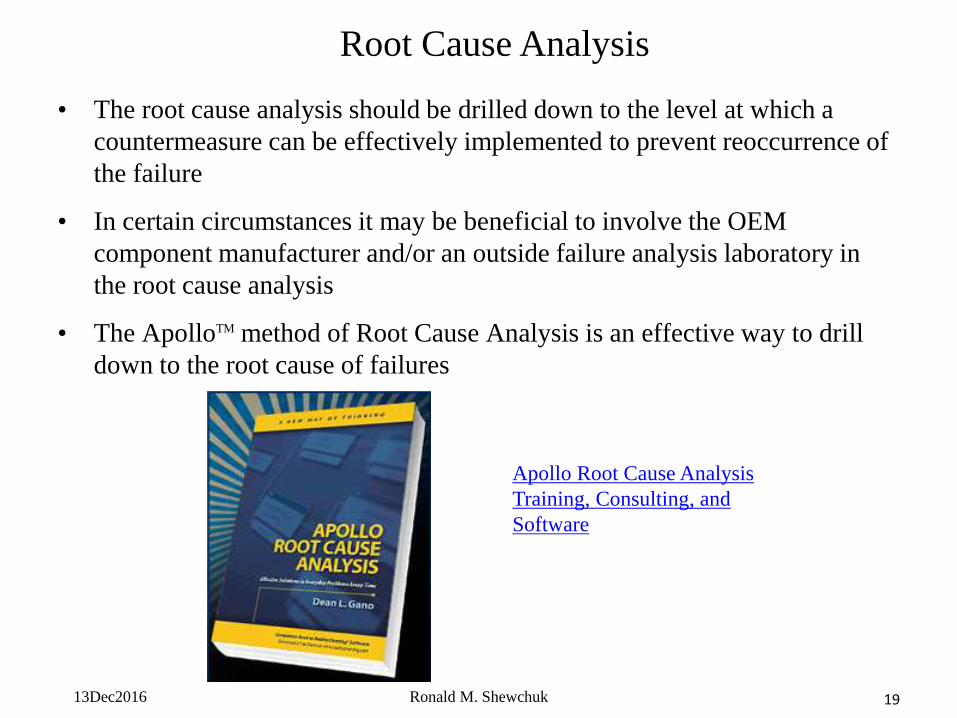
• The root cause analysis should be drilled down to the level at which a
countermeasure can be effectively implemented to prevent reoccurrence of
the failure
• In certain circumstances it may be beneficial to involve the OEM
component manufacturer and/or an outside failure analysis laboratory in
the root cause analysis
• The ApolloTM method of Root Cause Analysis is an effective way to drill
down to the root cause of failures
Apollo Root Cause Analysis
Training, Consulting, and
Software
13Dec2016 Ronald M. Shewchuk 20
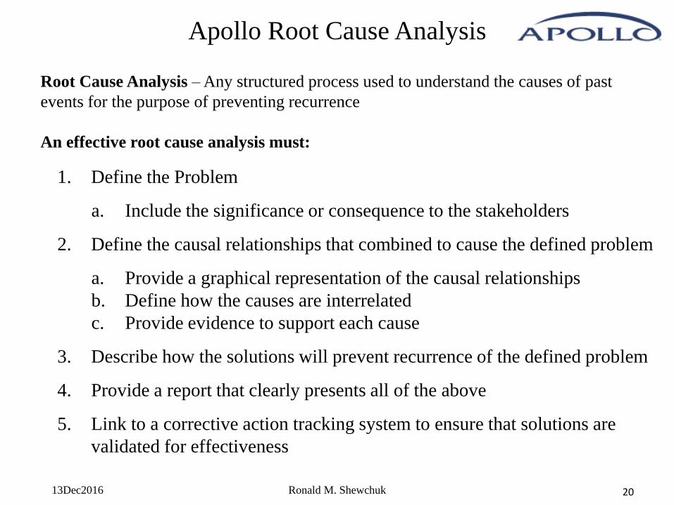
Apollo Root Cause Analysis
Root Cause Analysis – Any structured process used to understand the causes of past
events for the purpose of preventing recurrence
An effective root cause analysis must:
1. Define the Problem
a. Include the significance or consequence to the stakeholders
2. Define the causal relationships that combined to cause the defined problem
a. Provide a graphical representation of the causal relationships
b. Define how the causes are interrelated
c. Provide evidence to support each cause
3. Describe how the solutions will prevent recurrence of the defined problem
4. Provide a report that clearly presents all of the above
5. Link to a corrective action tracking system to ensure that solutions are
validated for effectiveness
13Dec2016 Ronald M. Shewchuk 21
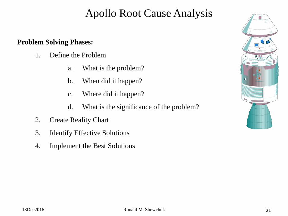
Apollo Root Cause Analysis
Problem Solving Phases:
1. Define the Problem
a. What is the problem?
b. When did it happen?
c. Where did it happen?
d. What is the significance of the problem?
2. Create Reality Chart
3. Identify Effective Solutions
4. Implement the Best Solutions
13Dec2016 Ronald M. Shewchuk 22
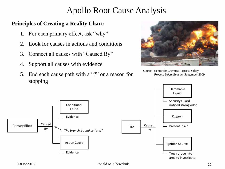
Apollo Root Cause Analysis
Principles of Creating a Reality Chart:
1. For each primary effect, ask “why”
2. Look for causes in actions and conditions
3. Connect all causes with “Caused By”
4. Support all causes with evidence
5. End each cause path with a “?” or a reason for
stopping
Primary Effect
Conditional Cause
Action Cause
Evidence
Evidence
Caused
ByThe branch is read as “and”
Fire
Flammable Liquid
Ignition Source
Security Guard noticed strong odor
Truck drove into area to investigate
Caused
By
Oxygen
Present in air
Source: Center for Chemical Process Safety
Process Safety Beacon, September 2009
13Dec2016 Ronald M. Shewchuk 23
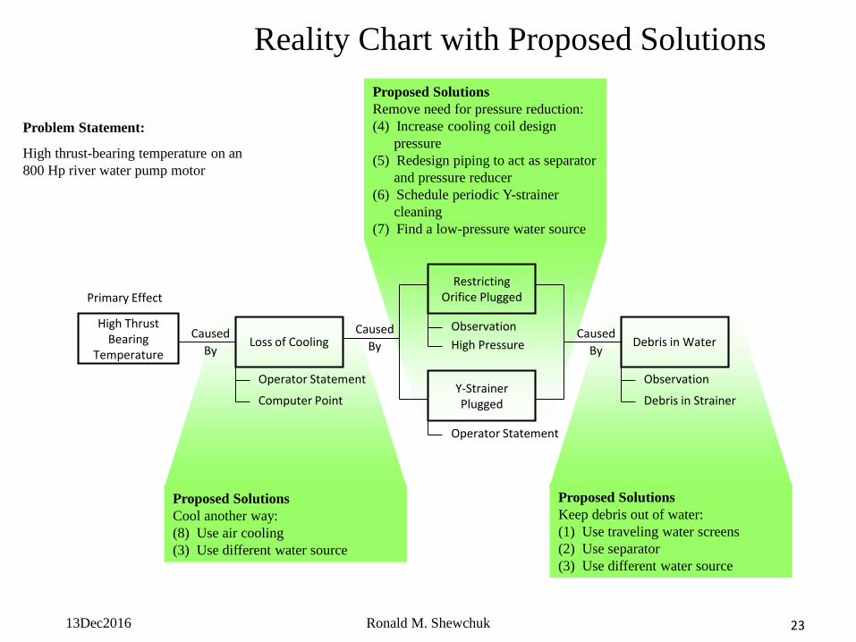
Proposed Solutions
Cool another way:
(8) Use air cooling
(3) Use different water source
Proposed Solutions
Keep debris out of water:
(1) Use traveling water screens
(2) Use separator
(3) Use different water source
Proposed Solutions
Remove need for pressure reduction:
(4) Increase cooling coil design
pressure
(5) Redesign piping to act as separator
and pressure reducer
(6) Schedule periodic Y-strainer
cleaning
(7) Find a low-pressure water source
Reality Chart with Proposed Solutions
High Thrust Bearing
TemperatureLoss of Cooling
Y-Strainer Plugged
Operator Statement
Operator Statement
Caused
By
Restricting Orifice Plugged
Observation
Primary Effect
Computer Point
Caused
By High PressureCaused
ByDebris in Water
Observation
Debris in Strainer
Problem Statement:
High thrust-bearing temperature on an
800 Hp river water pump motor
13Dec2016 Ronald M. Shewchuk 24
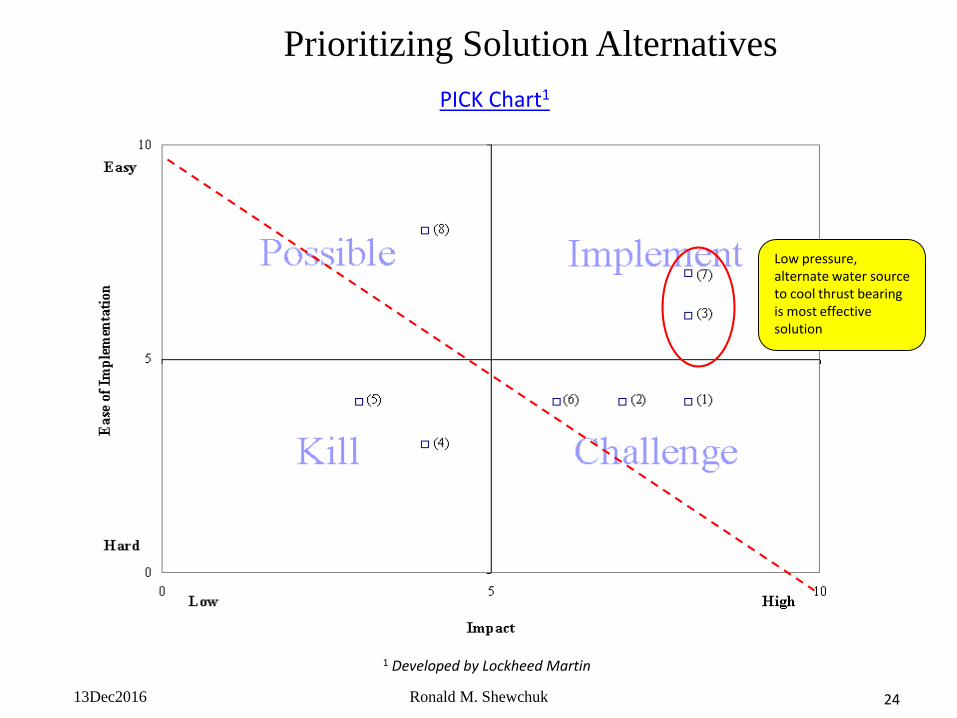
1 Developed by Lockheed Martin
*
Prioritizing Solution Alternatives
Low pressure, alternate water source to cool thrust bearing is most effective solution
PICK Chart1
13Dec2016 Ronald M. Shewchuk 25
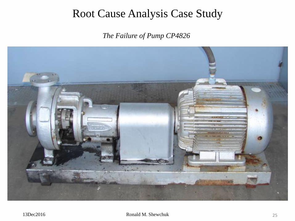
Root Cause Analysis Case Study
The Failure of Pump CP4826
13Dec2016 Ronald M. Shewchuk 26
Root Cause Analysis Case Study
The Story
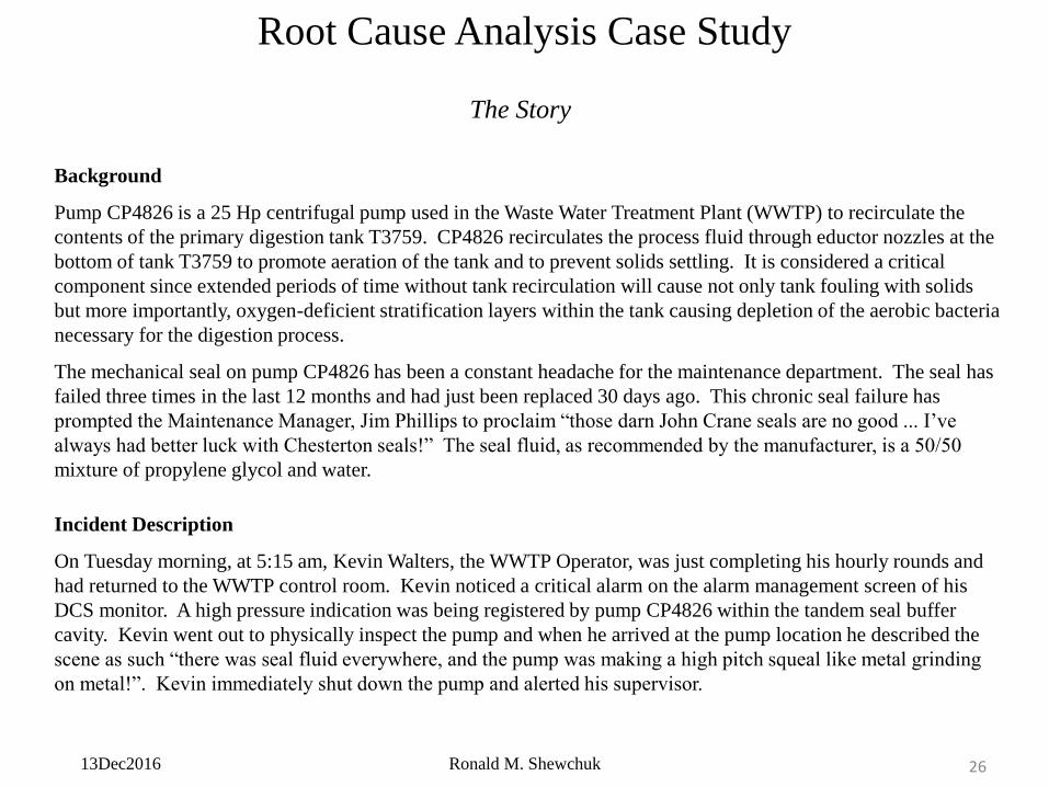
Background
Pump CP4826 is a 25 Hp centrifugal pump used in the Waste Water Treatment Plant (WWTP) to recirculate the
contents of the primary digestion tank T3759. CP4826 recirculates the process fluid through eductor nozzles at the
bottom of tank T3759 to promote aeration of the tank and to prevent solids settling. It is considered a critical
component since extended periods of time without tank recirculation will cause not only tank fouling with solids
but more importantly, oxygen-deficient stratification layers within the tank causing depletion of the aerobic bacteria
necessary for the digestion process.
The mechanical seal on pump CP4826 has been a constant headache for the maintenance department. The seal has
failed three times in the last 12 months and had just been replaced 30 days ago. This chronic seal failure has
prompted the Maintenance Manager, Jim Phillips to proclaim “those darn John Crane seals are no good ... I’ve
always had better luck with Chesterton seals!” The seal fluid, as recommended by the manufacturer, is a 50/50
mixture of propylene glycol and water.
Incident Description
On Tuesday morning, at 5:15 am, Kevin Walters, the WWTP Operator, was just completing his hourly rounds and
had returned to the WWTP control room. Kevin noticed a critical alarm on the alarm management screen of his
DCS monitor. A high pressure indication was being registered by pump CP4826 within the tandem seal buffer
cavity. Kevin went out to physically inspect the pump and when he arrived at the pump location he described the
scene as such “there was seal fluid everywhere, and the pump was making a high pitch squeal like metal grinding
on metal!”. Kevin immediately shut down the pump and alerted his supervisor.
13Dec2016 Ronald M. Shewchuk 27
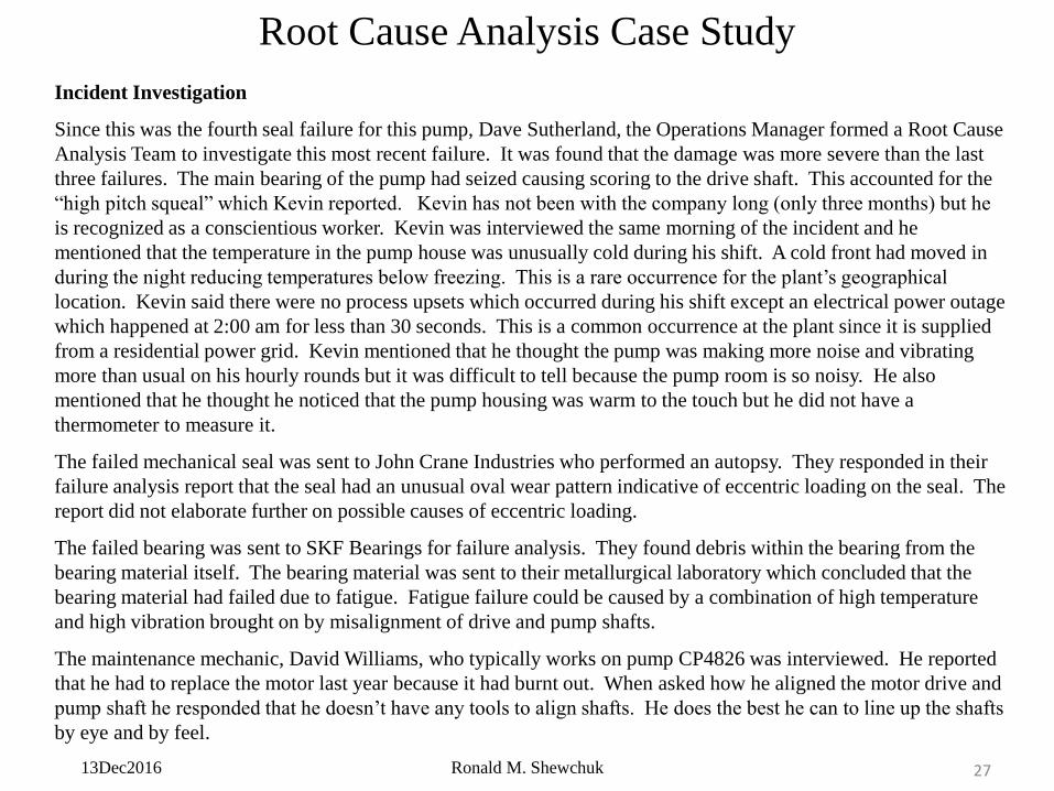
Incident Investigation
Since this was the fourth seal failure for this pump, Dave Sutherland, the Operations Manager formed a Root Cause
Analysis Team to investigate this most recent failure. It was found that the damage was more severe than the last
three failures. The main bearing of the pump had seized causing scoring to the drive shaft. This accounted for the
“high pitch squeal” which Kevin reported. Kevin has not been with the company long (only three months) but he
is recognized as a conscientious worker. Kevin was interviewed the same morning of the incident and he
mentioned that the temperature in the pump house was unusually cold during his shift. A cold front had moved in
during the night reducing temperatures below freezing. This is a rare occurrence for the plant’s geographical
location. Kevin said there were no process upsets which occurred during his shift except an electrical power outage
which happened at 2:00 am for less than 30 seconds. This is a common occurrence at the plant since it is supplied
from a residential power grid. Kevin mentioned that he thought the pump was making more noise and vibrating
more than usual on his hourly rounds but it was difficult to tell because the pump room is so noisy. He also
mentioned that he thought he noticed that the pump housing was warm to the touch but he did not have a
thermometer to measure it.
The failed mechanical seal was sent to John Crane Industries who performed an autopsy. They responded in their
failure analysis report that the seal had an unusual oval wear pattern indicative of eccentric loading on the seal. The
report did not elaborate further on possible causes of eccentric loading.
The failed bearing was sent to SKF Bearings for failure analysis. They found debris within the bearing from the
bearing material itself. The bearing material was sent to their metallurgical laboratory which concluded that the
bearing material had failed due to fatigue. Fatigue failure could be caused by a combination of high temperature
and high vibration brought on by misalignment of drive and pump shafts.
The maintenance mechanic, David Williams, who typically works on pump CP4826 was interviewed. He reported
that he had to replace the motor last year because it had burnt out. When asked how he aligned the motor drive and
pump shaft he responded that he doesn’t have any tools to align shafts. He does the best he can to line up the shafts
by eye and by feel.
Root Cause Analysis Case Study
13Dec2016 Ronald M. Shewchuk 28
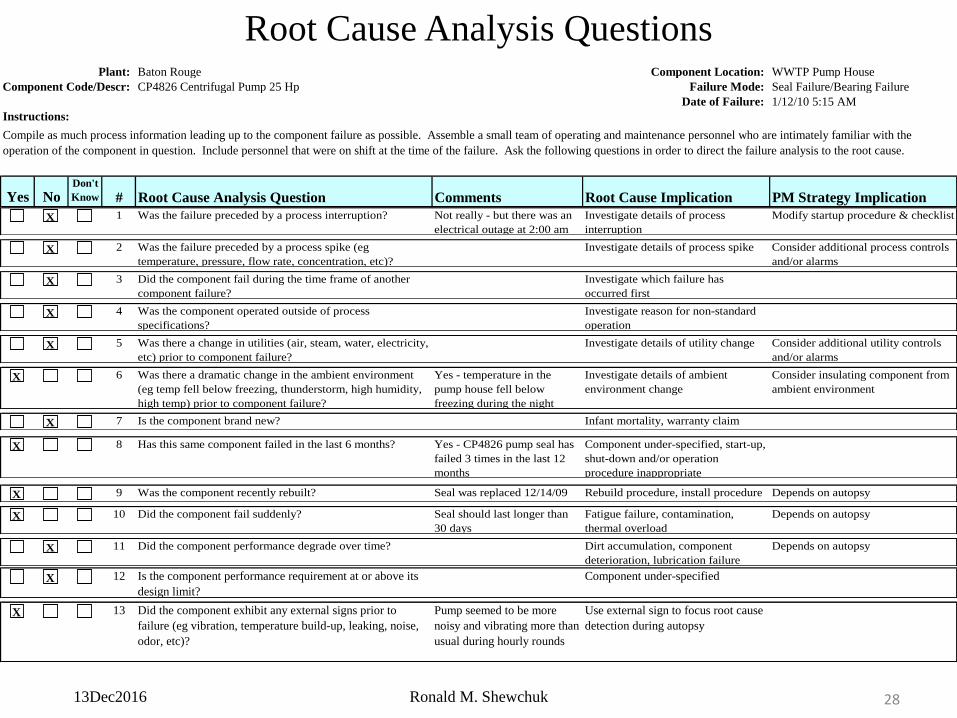
Root Cause Analysis Questions
1 Was the failure preceded by a process interruption? Not really - but there was an
electrical outage at 2:00 am
Investigate details of process
interruption
Modify startup procedure & checklistX
2 Was the failure preceded by a process spike (eg
temperature, pressure, flow rate, concentration, etc)?
Investigate details of process spike Consider additional process controls
and/or alarmsX
3 Did the component fail during the time frame of another
component failure?
Investigate which failure has
occurred firstX
4 Was the component operated outside of process
specifications?
Investigate reason for non-standard
operationX
5 Was there a change in utilities (air, steam, water, electricity,
etc) prior to component failure?
Investigate details of utility change Consider additional utility controls
and/or alarmsX
6 Was there a dramatic change in the ambient environment
(eg temp fell below freezing, thunderstorm, high humidity,
high temp) prior to component failure?
Yes - temperature in the
pump house fell below
freezing during the night
Investigate details of ambient
environment change
Consider insulating component from
ambient environmentX
7 Is the component brand new? Infant mortality, warranty claimX
8 Has this same component failed in the last 6 months? Yes - CP4826 pump seal has
failed 3 times in the last 12
months
Component under-specified, start-up,
shut-down and/or operation
procedure inappropriate
X
9 Was the component recently rebuilt? Seal was replaced 12/14/09 Rebuild procedure, install procedure Depends on autopsyX
10 Did the component fail suddenly? Seal should last longer than
30 days
Fatigue failure, contamination,
thermal overload
Depends on autopsyX
11 Did the component performance degrade over time? Dirt accumulation, component
deterioration, lubrication failure
Depends on autopsyX
12 Is the component performance requirement at or above its
design limit?
Component under-specifiedX
13 Did the component exhibit any external signs prior to
failure (eg vibration, temperature build-up, leaking, noise,
odor, etc)?
Pump seemed to be more
noisy and vibrating more than
usual during hourly rounds
Use external sign to focus root cause
detection during autopsyX
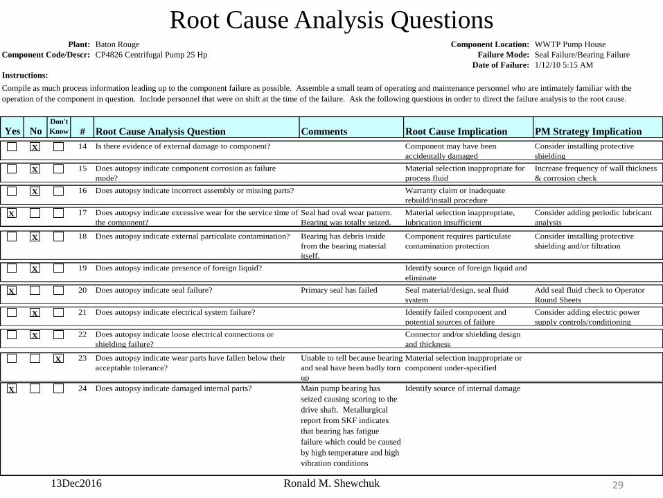
Plant: Baton Rouge Component Location: WWTP Pump House
Component Code/Descr: CP4826 Centrifugal Pump 25 Hp Failure Mode: Seal Failure/Bearing Failure
Date of Failure: 1/12/10 5:15 AM
Instructions:
Yes NoDon't
Know # Root Cause Analysis Question Comments Root Cause Implication PM Strategy Implication
Compile as much process information leading up to the component failure as possible. Assemble a small team of operating and maintenance personnel who are intimately familiar with the
operation of the component in question. Include personnel that were on shift at the time of the failure. Ask the following questions in order to direct the failure analysis to the root cause.
13Dec2016 Ronald M. Shewchuk 29
Plant: Baton Rouge Component Location: WWTP Pump House
Component Code/Descr: CP4826 Centrifugal Pump 25 Hp Failure Mode: Seal Failure/Bearing Failure
Date of Failure: 1/12/10 5:15 AM
Instructions:
Yes NoDon't
Know # Root Cause Analysis Question Comments Root Cause Implication PM Strategy Implication
Compile as much process information leading up to the component failure as possible. Assemble a small team of operating and maintenance personnel who are intimately familiar with the
operation of the component in question. Include personnel that were on shift at the time of the failure. Ask the following questions in order to direct the failure analysis to the root cause.
14 Is there evidence of external damage to component? Component may have been
accidentally damaged
Consider installing protective
shieldingX
15 Does autopsy indicate component corrosion as failure
mode?
Material selection inappropriate for
process fluid
Increase frequency of wall thickness
& corrosion checkX
16 Does autopsy indicate incorrect assembly or missing parts? Warranty claim or inadequate
rebuild/install procedureX
17 Does autopsy indicate excessive wear for the service time of
the component?
Seal had oval wear pattern.
Bearing was totally seized.
Material selection inappropriate,
lubrication insufficient
Consider adding periodic lubricant
analysisX
18 Does autopsy indicate external particulate contamination? Bearing has debris inside
from the bearing material
itself.
Component requires particulate
contamination protection
Consider installing protective
shielding and/or filtrationX
19 Does autopsy indicate presence of foreign liquid? Identify source of foreign liquid and
eliminateX
20 Does autopsy indicate seal failure? Primary seal has failed Seal material/design, seal fluid
system
Add seal fluid check to Operator
Round SheetsX
21 Does autopsy indicate electrical system failure? Identify failed component and
potential sources of failure
Consider adding electric power
supply controls/conditioningX
22 Does autopsy indicate loose electrical connections or
shielding failure?
Connector and/or shielding design
and thicknessX
23 Does autopsy indicate wear parts have fallen below their
acceptable tolerance?
Unable to tell because bearing
and seal have been badly torn
up
Material selection inappropriate or
component under-specifiedX
24 Does autopsy indicate damaged internal parts? Main pump bearing has
seized causing scoring to the
drive shaft. Metallurgical
report from SKF indicates
that bearing has fatigue
failure which could be caused
by high temperature and high
vibration conditions
Identify source of internal damageX
Root Cause Analysis Questions
13Dec2016 Ronald M. Shewchuk 30
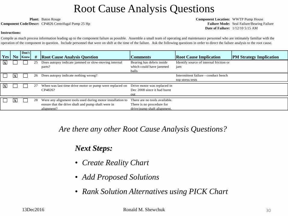
Plant: Baton Rouge Component Location: WWTP Pump House
Component Code/Descr: CP4826 Centrifugal Pump 25 Hp Failure Mode: Seal Failure/Bearing Failure
Date of Failure: 1/12/10 5:15 AM
Instructions:
Yes NoDon't
Know # Root Cause Analysis Question Comments Root Cause Implication PM Strategy Implication
Compile as much process information leading up to the component failure as possible. Assemble a small team of operating and maintenance personnel who are intimately familiar with the
operation of the component in question. Include personnel that were on shift at the time of the failure. Ask the following questions in order to direct the failure analysis to the root cause.
25 Does autopsy indicate jammed or slow-moving internal
parts?
Bearing has debris inside
which could have jammed
balls
Identify source of internal friction or
jamX
26 Does autopsy indicate nothing wrong? Intermittent failure - conduct bench
top stress testsX
27 When was last time drive motor or pump were replaced on
CP4826?
Drive motor was replaced in
Dec 2008 since it had burnt
out
X
28 Were any alignment tools used during motor installation to
ensure that the drive shaft and pump shaft were in
alignment?
There are no tools available.
There is no procedure for
drive/pump shaft alignment.
X
Are there any other Root Cause Analysis Questions?
Next Steps:
• Create Reality Chart
• Add Proposed Solutions
• Rank Solution Alternatives using PICK Chart
Root Cause Analysis Questions
13Dec2016 Ronald M. Shewchuk 31
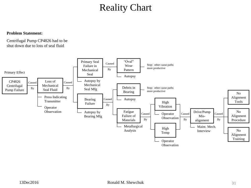
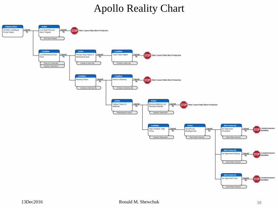
Reality Chart
CP4826
Centrifugal
Pump Failure
Primary Effect
Problem Statement:
Centrifugal Pump CP4826 had to be
shut down due to loss of seal fluid
Operator
Observation
Press Indicating
Transmitter
Loss of
Mechanical
Seal Fluid
Caused
By
High
Temp
Operator
Observation
High
Vibration
Operator
Observation
Caused
By
Drive/Pump
Mis-
alignment
Maint. Mech.
Interview
Caused
By
Fatigue
Failure of
Materials
Metallurgical
Analysis
Debris in
Bearing
AutopsyCaused
By
Caused
By
Bearing
Failure
Autopsy by
Bearing Mfg
Primary Seal
Failure in
Mechanical
Seal
Autopsy by
Mechanical
Seal Mfg
Caused
By
“Oval”
Wear
Pattern
Autopsy
Stop: other cause paths
more productive
No
Alignment
Tools
No
Alignment
Procedure
No
Alignment
Training
Caused
By
Stop: other cause paths
more productive
13Dec2016 Ronald M. Shewchuk 32
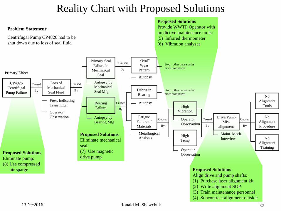
Reality Chart with Proposed Solutions
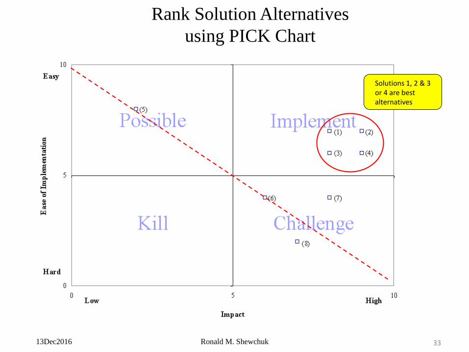
Proposed Solutions
Eliminate pump:
(8) Use compressed
air sparge
Proposed Solutions
Eliminate mechanical
seal:
(7) Use magnetic
drive pump
Proposed Solutions
Align drive and pump shafts:
(1) Purchase laser alignment kit
(2) Write alignment SOP
(3) Train maintenance personnel
(4) Subcontract alignment outside
Proposed Solutions
Provide WWTP Operator with
predictive maintenance tools:
(5) Infrared thermometer
(6) Vibration analyzer
CP4826
Centrifugal
Pump Failure
Primary Effect
Problem Statement:
Centrifugal Pump CP4826 had to be
shut down due to loss of seal fluid
Operator
Observation
Press Indicating
Transmitter
Loss of
Mechanical
Seal Fluid
Caused
By
High
Temp
Operator
Observation
High
Vibration
Operator
Observation
Caused
By
Drive/Pump
Mis-
alignment
Maint. Mech.
Interview
Caused
By
Fatigue
Failure of
Materials
Metallurgical
Analysis
Debris in
Bearing
AutopsyCaused
By
Caused
By
Bearing
Failure
Autopsy by
Bearing Mfg
Primary Seal
Failure in
Mechanical
Seal
Autopsy by
Mechanical
Seal Mfg
Caused
By
“Oval”
Wear
Pattern
Autopsy
Stop: other cause paths
more productive
No
Alignment
Tools
No
Alignment
Procedure
No
Alignment
Training
Caused
By
Stop: other cause paths
more productive
13Dec2016 Ronald M. Shewchuk 33
Rank Solution Alternatives
using PICK Chart
Solutions 1, 2 & 3or 4 are best alternatives
13Dec2016 Ronald M. Shewchuk 34
Apollo Reality Charting Software
13Dec2016 Ronald M. Shewchuk 35
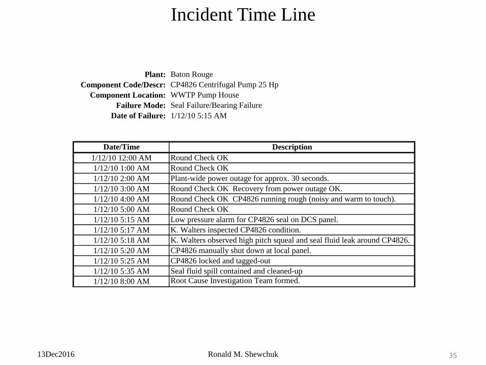
Incident Time Line
Plant: Baton Rouge
Component Code/Descr: CP4826 Centrifugal Pump 25 Hp
Component Location: WWTP Pump House
Failure Mode: Seal Failure/Bearing Failure
Date of Failure: 1/12/10 5:15 AM
Date/Time Description
1/12/10 12:00 AM Round Check OK
1/12/10 1:00 AM Round Check OK
1/12/10 2:00 AM Plant-wide power outage for approx. 30 seconds.
1/12/10 3:00 AM Round Check OK Recovery from power outage OK.
1/12/10 4:00 AM Round Check OK CP4826 running rough (noisy and warm to touch).
1/12/10 5:00 AM Round Check OK
1/12/10 5:15 AM Low pressure alarm for CP4826 seal on DCS panel.
1/12/10 5:17 AM K. Walters inspected CP4826 condition.
1/12/10 5:18 AM K. Walters observed high pitch squeal and seal fluid leak around CP4826.
1/12/10 5:20 AM CP4826 manually shut down at local panel.
1/12/10 5:25 AM CP4826 locked and tagged-out
1/12/10 5:35 AM Seal fluid spill contained and cleaned-up
1/12/10 8:00 AM Root Cause Investigation Team formed.
13Dec2016 Ronald M. Shewchuk 36
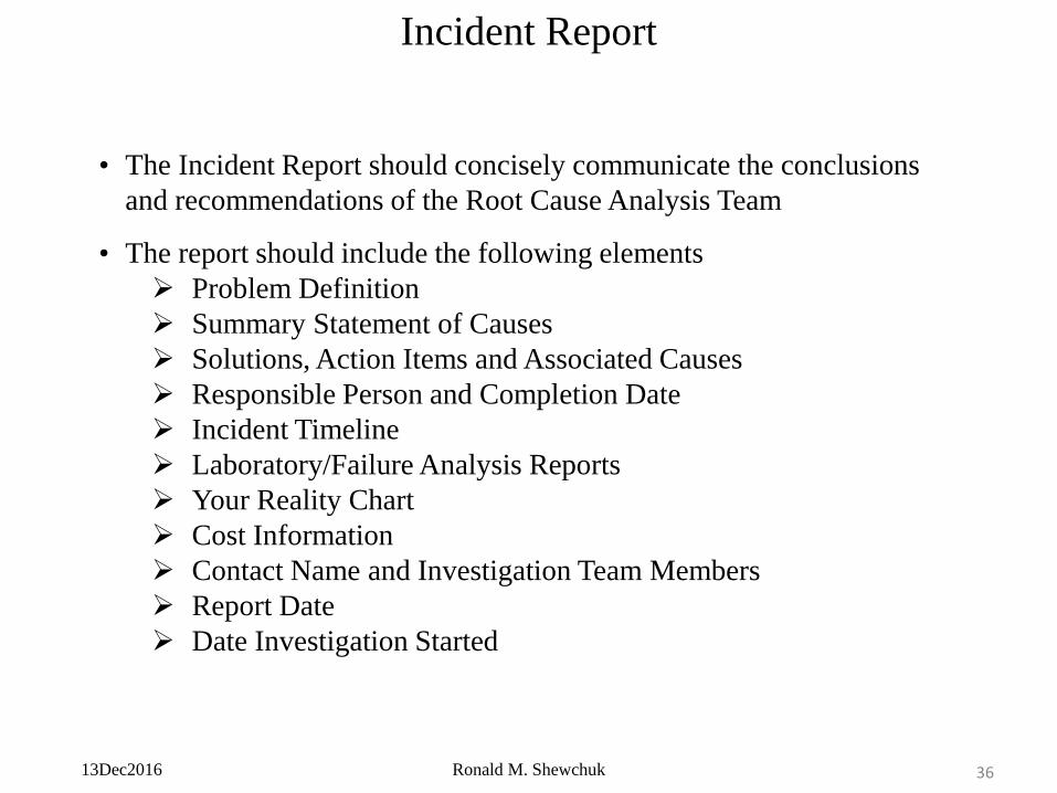
Incident Report
• The Incident Report should concisely communicate the conclusions
and recommendations of the Root Cause Analysis Team
• The report should include the following elements
Problem Definition
Summary Statement of Causes
Solutions, Action Items and Associated Causes
Responsible Person and Completion Date
Incident Timeline
Laboratory/Failure Analysis Reports
Your Reality Chart
Cost Information
Contact Name and Investigation Team Members
Report Date
Date Investigation Started
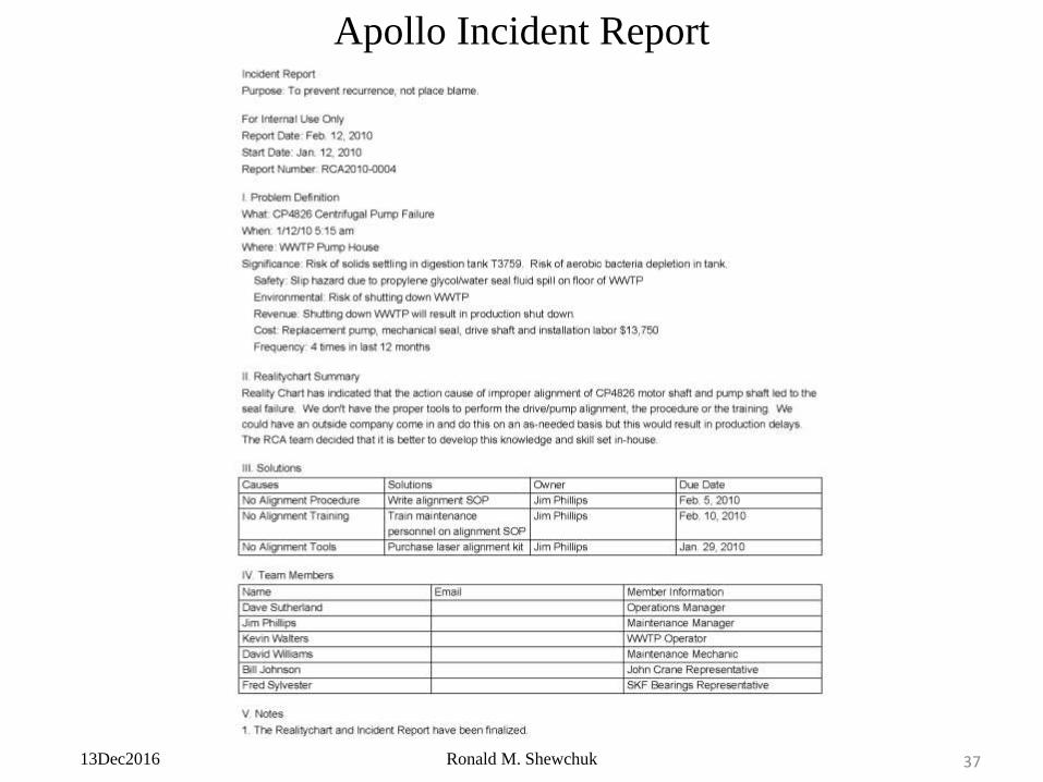
13Dec2016 Ronald M. Shewchuk 37
Apollo Incident Report
13Dec2016 Ronald M. Shewchuk 38
Apollo Reality Chart
13Dec2016 Ronald M. Shewchuk 39
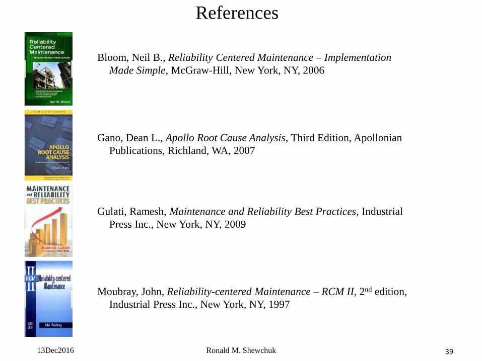
References
Bloom, Neil B., Reliability Centered Maintenance – Implementation
Made Simple, McGraw-Hill, New York, NY, 2006
Moubray, John, Reliability-centered Maintenance – RCM II, 2nd edition,
Industrial Press Inc., New York, NY, 1997
Gano, Dean L., Apollo Root Cause Analysis, Third Edition, Apollonian
Publications, Richland, WA, 2007
Gulati, Ramesh, Maintenance and Reliability Best Practices, Industrial
Press Inc., New York, NY, 2009
13Dec2016 Ronald M. Shewchuk 40
Internet Resources
• Society of Maintenance and Reliability Professionals
http://www.smrp.org/
• Plant Maintenance Resource Center
http://plant-maintenance.com/
• Maintenance Technology Magazine
http://www.mt-online.com/
• Apollo Root Cause Analysis
http://www.apollorca.com/
• Reliability Engineering Resources
http://www.weibull.com/
• GE Sensing & Inspection Technologies
http://www.geinspectiontechnologies.com/en/products/index.html
• Laser Alignment Tool
http://www.laser-alignment-tool.com/
13Dec2016 Ronald M. Shewchuk 41
Wrap-up
Thank you for your attention!
Are there any questions...?
Problems are the way we learn. Without effective methodology we remain in the dark.
Post tenebras spero lucem
…After darkness I expect the light