Solving a Coupling Unbalance Problem in the Field
23
Case Study 1 Solving a Coupling Unbalance Problem in the Field Author: Quraisy A. Shatri P.E. Maintenance Superintendent – Machinery and Reliability RasGas Company Limited PO Box 24200, Doha, State of Qatar Tel: (+974) 4492 3209 Mobile: (+974) 5583 8706 e-mail: [email protected] Author: Joseph P. (Joe) Corcoran Manager, Global Services and Training Kop-Flex Emerson Industrial Automation 7565 Harmans Road Hanover, MD USA 21076 Tel: (+1) 410 787 8522 Mobile (+1) 443 831 1811 e-mail: [email protected]
Transcript of Solving a Coupling Unbalance Problem in the Field

Case Study
1
Solving a Coupling Unbalance Problem in the Field
Author: Quraisy A. Shatri P.E.
Maintenance Superintendent – Machinery and Reliability
RasGas Company Limited
PO Box 24200, Doha, State of Qatar
Tel: (+974) 4492 3209
Mobile: (+974) 5583 8706
e-mail: [email protected]
Author: Joseph P. (Joe) Corcoran
Manager, Global Services and Training
Kop-Flex Emerson Industrial Automation
7565 Harmans Road
Hanover, MD USA 21076
Tel: (+1) 410 787 8522
Mobile (+1) 443 831 1811
e-mail: [email protected]

Abstract
2
When a large (3.4 meters long) diaphragm coupling was
suspected of causing excessive (120 microns p-p) 1X
unbalance vibration between a 90+ Megawatt Gas Turbine
and a Propane Compressor in an LNG plant, there was not
time to ship the coupling back to a distant factory or
service center for troubleshooting. Simple field diagnostic
techniques were used to discover the problem, which then
led to a field correction and repair so that the unit was able
to be quickly restarted with minimum downtime.

Process Background
3
In an LNG Plant, After all impurities such as Hg, H2S,H2O are removed in upstream units, sweet feed gas enters the gas chilling & liquefaction unit.
Two major pieces of equipment in this unit are the Scrub Column (SC) & the APCI Main Cryogenic Heat Exchanger
SC is a distillation column, steam re-boiled, to remove C5+ and provide streams for producing refrigerants (C2 and C3).
OH gas of the SC goes in to MCHE mid-bundle for liquefaction. The medium to cool is MR or Multi Component Refrigerant (MCR - C1+C2+C3+N2)

Process Background
4
The MR circuit is cooled (and partially liquefied) by Propane. The Propane refrigeration circuit is also tasked to cool Feed Gas in the gas chilling section, De-C2 condenser and the reinjection stream from the refrigerant preparation unit.
The two (2) main refrigeration compression circuits – MR & Propane – are illustrated in the next page.
If either of these 2 strings are down, there’ll be no production from the gas chilling & liquefaction unit, and no LNG is produced.

Simplified schematics
5

6
HM
Comp
56 MB
Comp
88 M Comp 7 EA Gas Turbine
Main Refrigeration Compression Strings
PROPANE
MR
#5.5 MSMH-J,
Diaphragm coupling
rated power≅ 92MW;
3,352.8 mm (Nominal
cold shaft separation)
HM
Comp 56 MB
Comp 60 M Comp 7EA Gas Turbine

RCA The string comprises of 4 coupled rotors: 7EA GT rotor, 88M and 56MB compressor
rotors – HM rotor
Bearings: 3 radial bearings for a single shaft 7EA rotor, 2 radial bearings each of 88M and 56MB rotors, and 2 radial bearings of the HM.
Only DE radial vibration of the 88M rotor was extremely high – increasing rapidly with increasing speed / load; other bearings-vibe readings were normal.
Refurbished 7EA rotor and upgraded (new) 88M rotor were installed during the turn-around. The GT operating data indicated “perfect”; factory dimensional and high-speed balance data of the 88M rotor and as-installed records indicated everything was acceptable.
Strong suspect was load coupling #5.5 MSMH-J based on possible coupling imbalance as seen via 88M DE vibe plots: new spools & adapter but old coupling-hub were assembled; wrong pre-stretch gap; and poor run-out. Coupling components individual balance records observed to be “perfect”.
On attending the unit, installed couplings run-out checks clearly showed the coupling straightness was grossly out-of- straightness (0.018”) in mid-span point.
Plans to index, change-out of coupling hub was cancelled; previously-installed spacers were re-installed after all necessary checks were done and certified acceptable. Run-out checks of the installed coupling was then checked and certified acceptable for services.
The whole string was started-up, sent in to normal operations satisfactorily.

High Vibration – Coupling Suspected
8

High Vibration – Coupling Suspected
9

Before Disassembling Coupling Installed Runout was Checked
10
-This is Not Normally Done but Can Provide Important
Information
-Sometimes Difficult to Turn Over Machines
-Many Ways to Overcome
-Jog Motor (If Motor)
-Use Turning Gear
-Even Overhead Crane can be Used with Long Strap
Wound Around Coupling or Shaft
Run Out Should Typically be No Greater Than
0.002” TIR at Flange Connections
0.001” TIR at Hub Bodies

Field Installed Run Out Check of Coupling Confirm a Problem
11
0.45 mm TIR 0.20 mm
TIR
0.23mm
TIR
0.15mm
TIR
0.05 mm
TIR
0.03 mm
TIR
0.00 mm
TIR
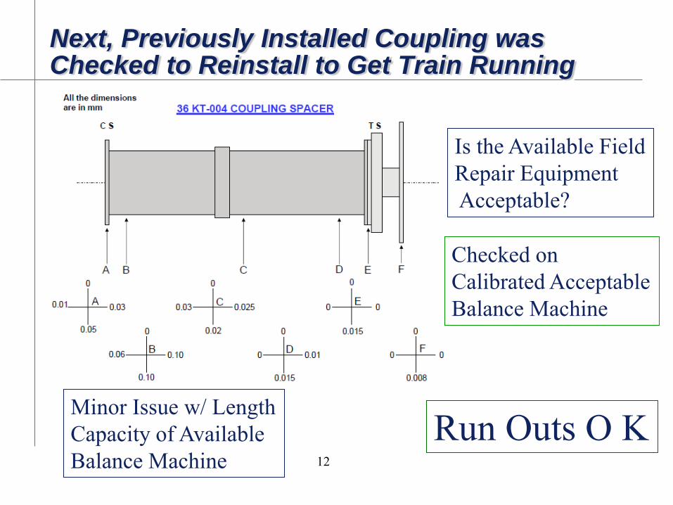
Next, Previously Installed Coupling was Checked to Reinstall to Get Train Running
12
Run Outs O K Minor Issue w/ Length
Capacity of Available
Balance Machine
Is the Available Field
Repair Equipment
Acceptable?
Checked on
Calibrated Acceptable
Balance Machine
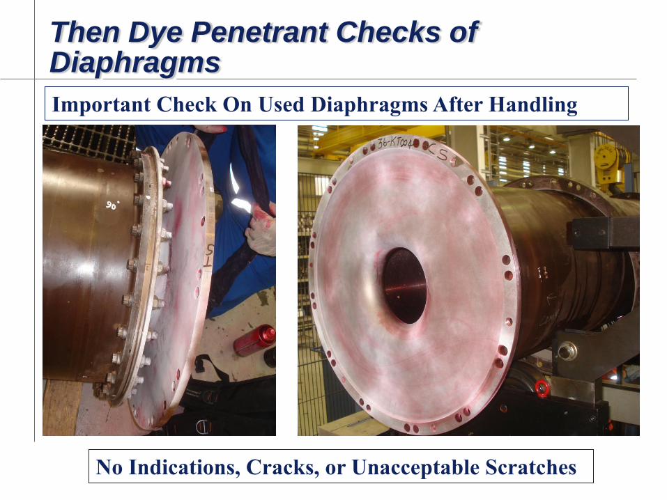
Then Dye Penetrant Checks of Diaphragms
13
Important Check On Used Diaphragms After Handling
No Indications, Cracks, or Unacceptable Scratches
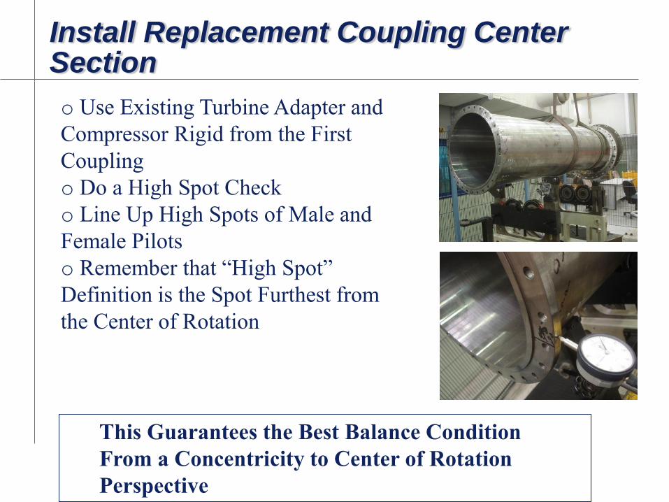
Install Replacement Coupling Center Section
o Use Existing Turbine Adapter and
Compressor Rigid from the First
Coupling
o Do a High Spot Check
o Line Up High Spots of Male and
Female Pilots
o Remember that “High Spot”
Definition is the Spot Furthest from
the Center of Rotation
This Guarantees the Best Balance Condition
From a Concentricity to Center of Rotation
Perspective

Installed Replacement Coupling Run Out Checks
15
0.15 mm
TIR
0.10 mm
TIR
0.10 mm
TIR
0.05 mm
TIR
0.10 mm
TIR
0.03 mm
TIR
0.00 mm
TIR
0.10 mm
TIR
No Problem

Runout Checks are Good and New Vibration Plots are Good
16

Proof: Vibration Plots are Good
17 Before and After

Proof: Vibration Plots are Good
18
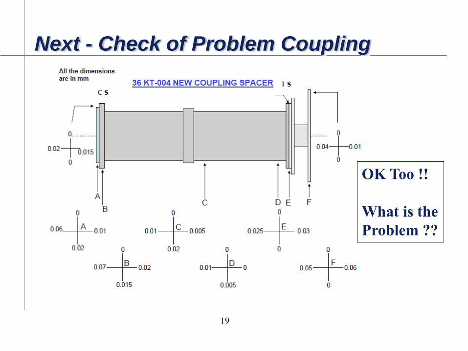
Next - Check of Problem Coupling
19
OK Too !!
What is the
Problem ??

What Could Have Been the Problem?
20
-Installed Run Outs at Positions Other Than Spacer - OK
-Mounting Flange and Adapter - OK
-Hub Mounting Surfaces - OK
-Then we remembered a comment about the difficulty of
connecting to the Turbine flange
-Re-look at Coupling/Turbine Mounting Surfaces

Aha !! ; Clear Evidence of a Mounting Problem
21
Connecting Flanges were not Contacting and were out of
Square Even Though Bolts Were Tightened Properly
This out of Square caused the Mounted Center Flange High Runout
Correct Fit-Up

Recommendations
22
-Improve Existing Turbine Flange Connection for Ease of Assembly
-Reduce Width of Guard Pilot
-Reduce Amount of Interference at Pilot
-Improve Overall Flange Connection Design
-Use Standard Design Bolting
-Improve Procedure
-Leave Coupling Adapter in Place
-Handle Diaphragms “Gingerly”

Lessons Learned
23
-If Coupling Balance is Suspected, Check Installed Run-outs
-If Replacing Non-Match Marked Components, Find “High
Spots” and Match Them
-Dye Check or MPI used and/or handled Coupling
Diaphragms
-Carefully Handle any Diaphragm
- Do not lay face down on rough surface
-Understand Installation Potential Difficulties When
Designing Coupling