SOLUTIONS FOR THE CONSTRUCTION OF PRECAST …...DESIGN AND CONSTRUCT ION OF SEGMENTAL BOX GIRDER...
22
SOLUTIONS FOR THE CONSTRUCTION OF PRECAST SEGMENTAL BRIDGES – REVIEW OF SYDNEY’S M7 PROJECT AND OTHER REGIONAL APPLICATIONS INTRODUCTION OF THE SPEAKERS: Part A – Construction Solutions for Concrete bridges Speaker: Mr David TRAYNER 1 Current Role: Operations Manager NSW / Pacific For: VSL Australia Pty Ltd Past Experience: Asian Regional Manager for Heavy Lifting Operations for VSL. Based regionally in Thailand / Singapore for 13 years. Worked on several major engineering Projects including the New Bangkok International Airport (Thailand), Chicago Beach Tower Resort Dubai (UAE), Petronas Twin Towers – Skybridge (Malaysia), Tsing Ma Bridge (Hong Kong), erection of various bridge structures including NS4 Second Stage Expressway (pre-cast segmental), (Thailand), NS Link (Indonesia), Nanjing 2 nd Bridge (China) and other related lifting and placing operations. Part B – M7 Case Study Speaker: Mr Gerry VAN DER WAL 2 Current Role: Project Manager - Segmental Bridges For: Abigroup Leighton Joint Venture – Westlink M7 Project Past Experience: Worked on several major civil engineering Projects in the UK, (7 years), Malaysia (6 years) and Australia (2 years) with 10 of these on precast segmental viaducts. Cast and installed over 10000 segments using short line and long line methods with installation methods by span by span (with over head and underslung truss), falsework, BC with cranes and over head trusses. Segment weights from 40 to 140t. ABSTRACT The utilisation of pre-cast segmental bridges to solve modern infrastructure problems is a cost effective, efficient and increasingly popular solution. Their structural diversity, constructability and general aesthetics has added to their success around the world in both developed and developing nations a like. A fundamental issue with pre-cast segmental structures is their method of erection. These methods are numerous and include placement by gantries, cranes, on falsework, by lifting frames and so on. The form of these structures also vary considerably and are influenced by many factors including span lengths, loadings, geographical location, topography, environmental issues, political agendas, whether they have wet or dry joints, internal or external post tensioning and the type of erection methodology employed such as span by span and/or balanced cantilever construction. This paper is divided into 2 parts; part A gives an introductory discussion on construction solutions for concrete bridges leading to the factors and techniques typically employed on pre-cast segmental bridges. Part B finishes the presentation with a detailed case study of Sydney’s 40 km long Westlink M7 project with its 150 bridges currently nearing completion. This project contains a variety of construction techniques and provides a valuable insight into how differing solutions can be successfully incorporated from design to project completion.
Transcript of SOLUTIONS FOR THE CONSTRUCTION OF PRECAST …...DESIGN AND CONSTRUCT ION OF SEGMENTAL BOX GIRDER...

SOLUTIONS FOR THE CONSTRUCTION OF PRECAST SEGMENTAL BRIDGES – REVIEW OF SYDNEY’S M7 PROJECT AND OTHER REGIONAL APPLICATIONS INTRODUCTION OF THE SPEAKERS: Part A – Construction Solutions for Concrete bridges Speaker: Mr David TRAYNER1 Current Role: Operations Manager NSW / Pacific For: VSL Australia Pty Ltd Past Experience: Asian Regional Manager for Heavy Lifting Operations for VSL. Based regionally in Thailand / Singapore for 13 years. Worked on several major engineering Projects including the New Bangkok International Airport (Thailand), Chicago Beach Tower Resort Dubai (UAE), Petronas Twin Towers – Skybridge (Malaysia), Tsing Ma Bridge (Hong Kong), erection of various bridge structures including NS4 Second Stage Expressway (pre-cast segmental), (Thailand), NS Link (Indonesia), Nanjing 2nd Bridge (China) and other related lifting and placing operations. Part B – M7 Case Study Speaker: Mr Gerry VAN DER WAL2 Current Role: Project Manager - Segmental Bridges For: Abigroup Leighton Joint Venture – Westlink M7 Project Past Experience: Worked on several major civil engineering Projects in the UK, (7 years), Malaysia (6 years) and Australia (2 years) with 10 of these on precast segmental viaducts. Cast and installed over 10000 segments using short line and long line methods with installation methods by span by span (with over head and underslung truss), falsework, BC with cranes and over head trusses. Segment weights from 40 to 140t.
ABSTRACT The utilisation of pre-cast segmental bridges to solve modern infrastructure problems is a cost effective, efficient and increasingly popular solution. Their structural diversity, constructability and general aesthetics has added to their success around the world in both developed and developing nations a like. A fundamental issue with pre-cast segmental structures is their method of erection. These methods are numerous and include placement by gantries, cranes, on falsework, by lifting frames and so on. The form of these structures also vary considerably and are influenced by many factors including span lengths, loadings, geographical location, topography, environmental issues, political agendas, whether they have wet or dry joints, internal or external post tensioning and the type of erection methodology employed such
as span by span and/or balanced cantilever construction. This paper is divided into 2 parts; part A gives an introductory discussion on construction solutions for concrete bridges leading to the factors and techniques typically employed on pre-cast segmental bridges. Part B finishes the presentation with a detailed case study of Sydney’s 40 km long Westlink M7 project with its 150 bridges currently nearing completion. This project contains a variety of construction techniques and provides a valuable insight into how differing solutions can be successfully incorporated from design to project completion.

_________________________ 1 Operations Manager NSW/Pacific VSL Australia Pty Ltd 2 Project Manager Abigroup Leighton Joint Venture – Westlink M7 Project PART A: CONSTRUCTION SOLUTIONS OF CONCRETE BRIDGES
1. INTRODUCTION Part A of this paper is directed towards the various solutions available for constructing larger (>35m) span concrete bridges. A variety of techniques are briefly investigated together with the advantages of each type of construction and the factors that may lend them selves favourably to their consideration. This discussion starts after having made the decision to go with a concrete structure but prior deciding to go either cast in-situ or to utilise a pre-cast option. Advantages of each option and influencing factors are thus reviewed leading to the final application of pre-cast segmental solution. The project examples used in the following article are from VSL’s project references only.
The success of the various construction solutions available is reflected in the staggering 5 million square metres of deck placed or more than 95,000 segments erected and stressed from projects with which VSL have had involvement in for the last 17 years only and limited to this region alone. These numbers exclude work carried out by others. 2. TYPES OF CONSTRUCTION
Concrete bridges can be divided into basically 2 types: i) Cast in-situ and ii) Pre-cast. For the purpose of definition we deem pre-cast structures as those that are principally cast somewhere else besides their final location. We also note that many structures contain a component of cast in-situ works such as decks and or parapets, however, as their principle components are pre-cast we define them as falling under a pre-cast solution.
Examples of cast in-situ bridge structures include: Description Photo Project Example Formtraveler 1 CC221155 HHii gghh SSppeeeedd RRaaii ll -- TTaaii wwaann MSS moveable scaffold system Cast in place girder
Photo: 1. VVSSLL MMOO DDUULLAARR FF OORRMM TTRRAAVVEELLEERR -- CC221155 HHiigghh SSppeeeedd RRaaii ll -- TTaaiiwwaann Advantages of cast in–situ include - Technical advantages
- Balanced cantilever suit larger spans, tighter curves / grades
- Commercial advantages include: - No pre-cast yard establishment costs - No specialised erection equipment
costs

Examples of pre-cast bridge structures include: Description Photo Project Example Incremental launch Method (ILM) 2 Brides Glen Bridge, Ireland T, U, I, beams, Planks 3 Cebu South Coast Rd, Philippines Full spans 4 High Speed Rail Project, Taiwan Segmental 5 Telok Blangah, Singapore Combined pre-cast + cable stay 6 Pakse, Laos Pier head rotation 7 Pier head rotation, Thailand
Photo 2. ILM Brides Glen Bridge, Ireland Photo. 3 Cebu South Coast Rd, Philippines Photo 4. High Speed Rail Project, Taiwan Photo 5. Telok Blangah, Singapore

Photo 6. Pakse, Laos Photo 7.Pier head Rotation Thailand Advantages - Speed - Logistics – minimal disruption to existing
services etc. - Cost effective when critical mass
achieved - QA high – production in factory like
controlled facility - Weather resistant - Production independent from site works
(off critical path) 3. SELECTION OF PRE-CAST SEGMENT
CONSTRUCTION The final decision to go either cast in-situ or pre-cast is also influenced by many external factors, which vary from project to project. These considerations include - Size of project, critical mass (> 1500m long
then precast segments become viable). - Location
o In city, traffic congestion mitigation
o Over water, over valley’s, over railway
o Available pier spacings - Availability of resources
o Labour (skill levels) o Erection systems, launching
gantries, formwork o Casting yards
- Programme speed
Typical reasons to go pre-cast segmental include:
- Varying bridge alignments, such as radii,
grades, cross falls - Greater structural diversity to
accommodate larger spans or configuration, i.e. relatively easy to vary web depths, flanges and hence their respective capacities
- Span sizing requires elements not available in the market i.e. typically > 35m
- Single box - Aesthetics deemed better than T
beams (or similar) (discouraged in some countries)
- Complete deck required to minimise on site works (safety, convenience)
- Delivery of segments over previously launched spans (avoids delivery along streets)
- Project is large enough to justify setting up casting yard (bridge length >1500m)
- Project is located in the city hence restricted working hours, traffic mitigation (limited to sub structure works). (erection of 4 segments per carriageway per 6 hr window achievable).
- Ambitious erection programme required (span erection rates of 2 days / span achievable).
- Region prone to adverse weather conditions (temperatures below zero – concreting / steel)
Having determined the bridge will be a pre-cast segmental structure the next major decision will be whether it will be erected in a “span by span” manner or a “balanced cantilever” arrangement. A “span by span” technique is one in which all the segments of a span are erected and held temporarily until the permanent post tensioning is installed and engaged. The resulting spans can thus be of a simply supported nature or made continuous over a number of spans with the introduction of “continuity post tensioning” over the supports. A “balanced cantilever” technique however, is one in which pairs of segments are erected so as to balance the induced construction moments over the supporting pier. Each segment or pair is thus stressed on to the developing span cantilevers one at a time. Continuity post tensioning is typically used to join spans together. Piers can be either monolithic to the pier or on bearings depending upon the designer’s requirements. Unbalanced moments can also be overcome by temporary propping, and or nailing applications. Relative
spans lengths are important to ensure there is no up lift in various load cases. In both techniques expansion joints are typically located over piers and hence joints within the span are avoided. The erection of balanced cantilever spans over an expansion joint are typically facilitated by providing temporary stressing bars locking the joint up until the span is completed. Post tensioning holds all the pre-cast segments together. Tendons can be either internal, external and or a combination of both. Internal tendons require “wet” or epoxy joints where as “dry” joints require fully external tendons. External tendons require encasement in HDPE ducting to provide corrosion protection and the deck joints may require a sealant to prevent water ingress in to the segment cavity. Wet joints also require a nominal compressive stress in the order of 0.15Mpa in order to fill voids at the interface. As a result, temporary stress bars are typically used to do this prior the installation of the permanent post tensioning. Both types of tendon would be grouted with a high performance cementitious grout.
Both types of structures have advantages over the other in particular circumstances. Their eventual selection for a project will once again depend largely on external factors and how these parameters are accommodate by the differing arrangements.
Advantages for a “span by span” arrangement include:
- Fast to erect – limited by delivery speed and placement device (full span is erected prior any other works)
- Well suited to smaller, repetitive bridge spans
Above View : External Post-Tensioning Inside Bridge SegmentSET VIADUCT, SWITZERLAND
- Typically lower cost option when erected on falsework (requires firm / level ground conditions)
Advantages for a “balanced cantilever” arrangement include: - Suitable for Longer spans i.e. > 50m - More difficult alignments including tighter
curves (horizontal & vertical), grades - A lighter (hence) cheaper placement
gantry is required typically required if erection by gantry.
4. ERECTION SYSTEMS FOR PRE-CAST
SEGMENTAL Both segmental “span by span” and “balanced cantilever” construction arrangements can be erected using similar techniques. These techniques are summarised as follows
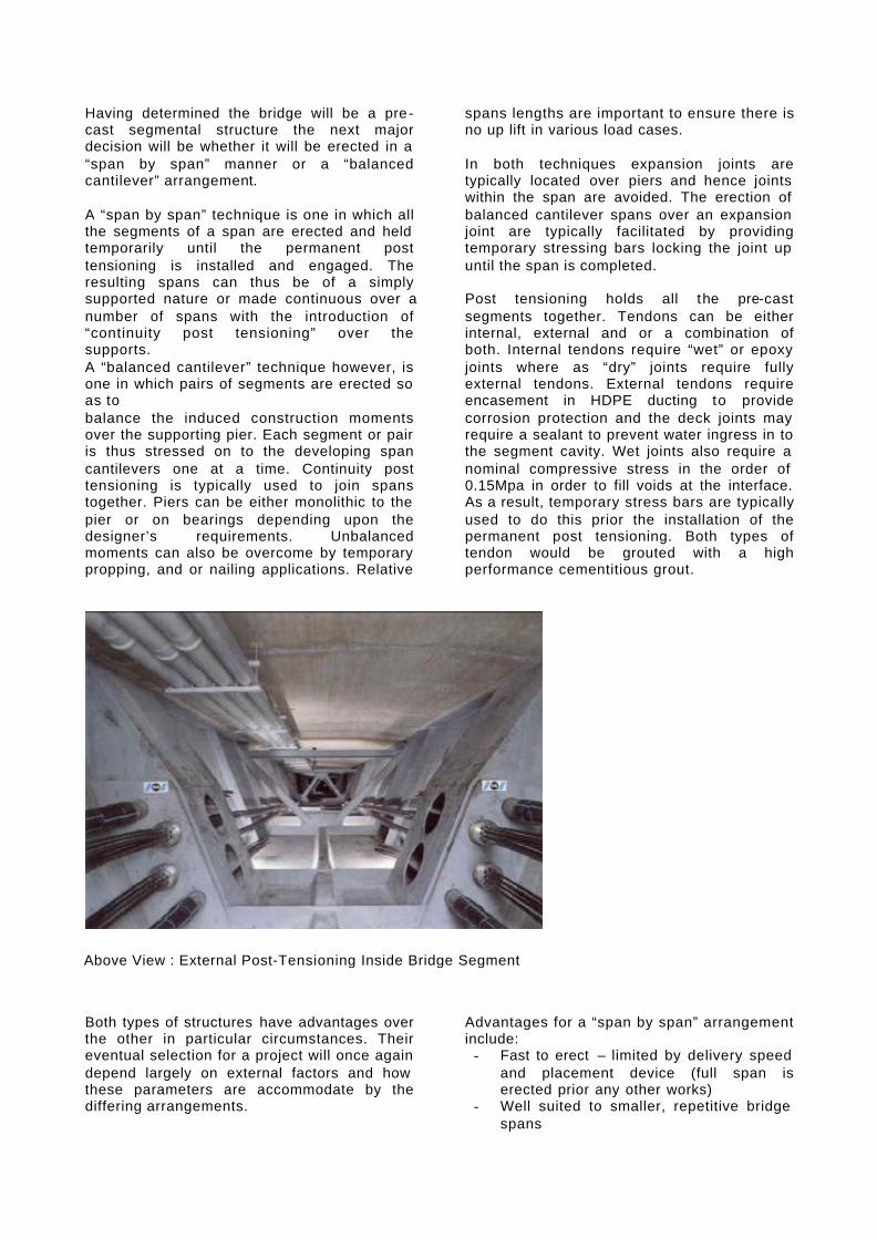
Description Photo Project Gantry - Over head - self launching / Self
placing - Balanced cantilever (BC) - Span by Span
- Underslung - self launching - crane launched
8 9 10
Shenzhen Western Corridor, HK Deep Bay Link, HK West Rail, HK
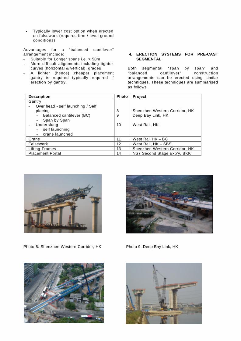
Crane 11 West Rail HK – BC Falsework 12 West Rail, HK – SBS Lifting Frames 13 Shenzhen Western Corridor, HK Placement Portal 14 NS7 Second Stage Exp’y, BKK
Photo 8. Shenzhen Western Corridor, HK Photo 9. Deep Bay Link, HK
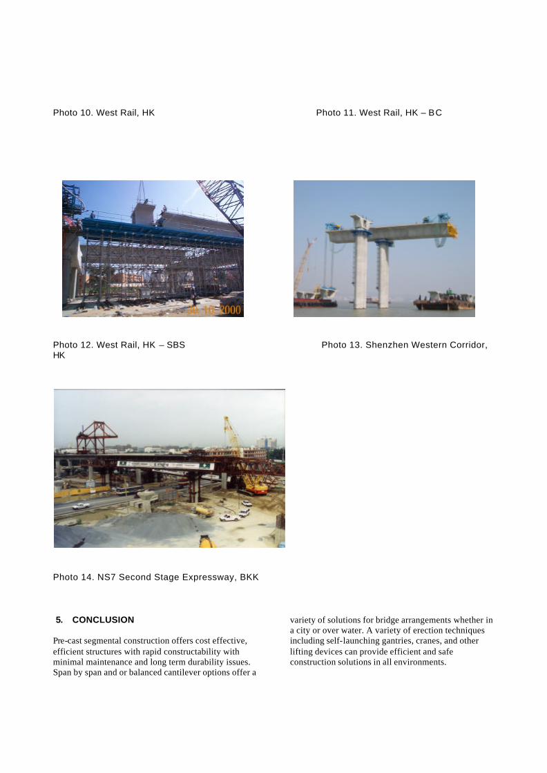
Photo 10. West Rail, HK Photo 11. West Rail, HK – BC Photo 12. West Rail, HK – SBS Photo 13. Shenzhen Western Corridor, HK
Photo 14. NS7 Second Stage Expressway, BKK 5. CONCLUSION
Pre-cast segmental construction offers cost effective, efficient structures with rapid constructability with minimal maintenance and long term durability issues. Span by span and or balanced cantilever options offer a
variety of solutions for bridge arrangements whether in a city or over water. A variety of erection techniques including self-launching gantries, cranes, and other lifting devices can provide efficient and safe construction solutions in all environments.

Part B – M7 Case Study
DESIGN AND CONSTRUCTION OF SEGMENTAL BOX GIRDER BRIDGES FOR THE WESTLINK M7 MOTORWAY
Geoff Bowmaker, Maunsell-SMEC Joint Venture, Westlink M71
Gerry van der Wal, Abigroup Leighton Joint Venture, Westlink M72
ABSTRACT The Westlink M7 project is a 40km dual carriageway motorway in western Sydney, connecting the M5 motorway at Prestons to the M2 Motorway at Baulkham Hills. The project includes the construction of 150 small to medium sized bridge structures, which comprise a s ignificant proportion of the overall project costs. Their timely construction is also a critical programming constraint on the completion of project and the early opening of the motorway. Standardisation of the bridges has been a major aim of the design. Conventional pretensioned precast concrete beam designs were chosen for bridges with spans up to 35m and precast segmental box girder bridges for the longer span bridges and motorway overbridges. Span by span box girder designs incorporating dry joints and external tendons
have been designed for the motorway viaducts and overbridges. Balanced cantilever segmental boxes incorporating epoxy joints and internal tendons have been designed for the longer span bridges at the major motorway interchanges and major road crossings. This paper discusses the design and construction of the segmental bridges. Design issues include the selection of the design criteria and construction specifications that were not adequately covered in the available Australian Codes, and adapting the design to suit the different construction methods and significant geometric variations. The construction involves the precasting and erection of 2,729 segments up to 15 m wide and 5 m in height. A dedicated factory was established for the precasting of the segments and the erection involved the use of erection gantries, falsework and free cantilevering methods.
__________________________ 1
Geoff Bowmaker, Maunsell – SMEC Joint Venture - Westlink M7 2 Gerry Van der Wal, AbigroupLeighton Joint Venture – Westlink M7
ACKNOWLEDGEMENTS: The authors wish to thank Westlink Motorway Limited, Abigroup Leighton Joint Venture, Maunsell-SMEC Joint Venture and the Roads and Traffic Authority of NSW for permission to publish this paper. The views expressed in this paper are those of the authors.

1. INTRODUCTION The Westlink M7 (WM7) project is a motorway link from the existing M5 at Prestons to the existing M2 at West Baulkham Hills and includes a major interchange where it crosses the M4 at Eastern Creek. It will provide 40km of dual carriageway in each direction and has been designed for a future public transport system in the wide central median. The project is large in geographical span and in the quantity of materials and resources required. The project includes 17 interchanges, 20 km of local road upgrades, 47 km shared pedestrian/cycle path, 7 million m3 of excavation, and 150 bridges. The two major interchanges with the M4 and M5 Motorways have provided the biggest challenges to the design and construct team. They involve the construction of more than 20 separate ramps at up to five different levels over some of the busiest sections of motorway in Australia. Impacts on the existing motorway must be minimised which has been a major driving force in the selection of the construction techniques. The project is a Build Own Operate and Transfer (BOOT) project between Roads and Traffic Authority of NSW (RTA) and Westlink Motorway Limited (Westlink). Westlink have contracted Abigroup / Leighton Joint Venture as the Construction Joint Venture (ALJV) for the design and construction of the WM7. Abigroup / Leighton have subsequently contracted the Maunsell / SMEC Joint Venture as lead consultants for the engineering design of WM7. The erection of the segmental bridges has been undertaken by an alliance between Abigroup / Leighton and VSL. The contract for works was signed in February 2003 with a contract construction period of 42 months and a construction price of $1.5 billion. 2. BRIDGES OF THE WM7 The large number of bridges on the WM7 project dictated that maximum use should be made of precasting in order to meet the very tight construction programme and thus Super-T girders and PSC planks were adopted for the majority of the bridges. Special structures were required for the longer span structures, especially those to be constructed over
existing motorways, and these were initially planned to be of steel box girder construction to minimise traffic delays during erection. During the concept design stage, assessments were made of the capabilities of the precast concrete and steel fabrication industries to supply the required number of components, and to minimise the risk to the construction programme, a new precasting facility was considered to be required. By adopting segmental precast box girders instead of Super-T’s for the long viaducts, it was possible to reduce the number of Super-T girders required on the project to manageable proportions that could be handled by the existing industries. In addition, the PSC box girders could be used for the ramp bridges and thus eliminate the need for fabricated curved steel girders. The use of precast concrete segmental girders also reduces the amount of in-situ concrete work. Various bridge configurations were then investigated to optimise the numbers of segments produced in the ALJV precast facility, and precast segmental box girders were subsequently adopted for: -
?? bridges with spans greater than 35 m (Old Windsor Road and Cowpasture Road);
?? all long multi -span viaducts (Hoxton Park viaducts, M4 viaducts and Old Windsor Road approach viaducts);
?? all curved ramp bridges at M4 and M5 interchanges; and
?? all bridges over the motorway. The overbridges were of spans tha t generally would not be constructed using precast segmental girders. By using this form of construction for the overbridges, however, the larger depth Super-T bridges were virtually eliminated from the project, and the appearance of the overbridges was considerably enhanced, particularly with respect to treatment at the central piers. Two different construction methods were adopted; externally prestressed spans erected using erection beams or falsework, or internally prestressed spans erected using the method of balanced cantilevering. Segments were match cast in the precast factory. A list of segmental box girder bridges is given in Table 1.
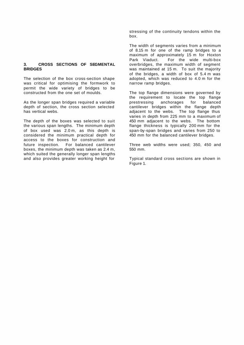
3. CROSS SECTIONS OF SEGMENTAL BRIDGES The selection of the box cross-section shape was critical for optimising the formwork to permit the wide variety of bridges to be constructed from the one set of moulds. As the longer span bridges required a variable depth of section, the cross section selected has vertical webs. The depth of the boxes was selected to suit the various span lengths. The minimum depth of box used was 2.0 m, as this depth is considered the minimum practical depth for access to the boxes for construction and future inspection. For balanced cantilever boxes, the minimum depth was taken as 2.4 m, which suited the generally longer span lengths and also provides greater working height for
stressing of the continuity tendons within the box. The width of segments varies from a minimum of 8.15 m for one of the ramp bridges to a maximum of approximately 15 m for Hoxton Park Viaduct. For the wide multi-box overbridges, the maximum width of segment was maintained at 15 m. To suit the majority of the bridges, a width of box of 5.4 m was adopted, which was reduced to 4.0 m for the narrow ramp bridges. The top flange dimensions were governed by the requirement to locate the top flange prestressing anchorages for balanced cantilever bridges within the flange depth adjacent to the webs. The top flange thus varies in depth from 225 mm to a maximum of 450 mm adjacent to the webs. The bottom flange thickness is typically 200 mm for the span-by -span bridges and varies from 250 to 450 mm for the balanced cantilever bridges. Three web widths were used; 350, 450 and 550 mm. Typical standard cross sect ions are shown in Figure 1.

TABLE 1 – WM7 SEGMENTAL BRIDGES Bridge Number
Location Overall Width
Length Area Number of Spans
Max Span length
Section Depth
Box width
No. of Boxes
Construction Method
Articulation No. of Segments
2.8 2.11 2.15 2.17
M5 Ramp (CVW Ramp over M7) M5 Ramp (M5 to M7) M5 Ramp (M7 over M5) M5 Ramp (M7 over N/B ramp)
13.64 max 12.34 21.84
13.52 max
135.8156.5197.7120.6
1786 1931 4318 1423
5 4 4 3
32.0 45.0 59.1 45.0
2.0 2.4 2.8 2.4
5.4 5.4 5.4 5.4
1 1 2 1
Span-by-Span Cantilever Cantilever Span-by-Span
SS cts cts cts
50 55
135 43
4 Overbridge - Kurrajong Rd 21.12 132.5 2797 4 35.0 2.0 5.4 2 Span-by-Span SS and cts 96 8.0 8.1
Hoxton Park Viaduct Northbound Hoxton Park Viaduct Southbound
14.7 max 14.9 max
626.1651.0
8828 9309
22 24
32.0 31.9
2.0 2.0
5.4 5.4
1 1
Span-by-Span Span-by-Span
SS SS
233 257
10.0 10.1
Cowpasture Road Northbound Cowpasture Road Southbound
11.64 11.64
145.9145.9
1698 1698
3 3
64.5 64.5
2.4 to 3.2 2.4 to 3.2
5.4 5.4
1 1
Cantilever Cantilever
cts cts
52 52
17.10 17.11
Elizabeth Drive Northbound Elizabeth Drive Southbound
11.64 11.64
64.164.1
746 746
2 2
33.5 33.5
2.0 2.0
5.4 5.4
1 1
Span-by-Span Span-by-Span
cts cts
23 23
21.1 23
25.9
Overbridge - Horsely Drive Overbridge - Chandos Rd Overbridge - Old Wallgrove Rd
58.34 14.74 23.14
52.164.169.1
3040 945
1598
2 2 2
28.0 33.5 35.1
2.0 2.0 2.0
5.4 5.4 5.4
4 1 2
Span-by-Span Span-by-Span Span-by-Span
cts cts cts
76 23 50
26.6 26.7
M4 Viaduct Northbound M4 Viaduct Southbound
11.64 11.64
398.8334.8
4642 3897
13 11
32.6 32.0
2.0 2.0
5.4 5.4
1 1
Span-by-Span Span-by-Span
SS SS
143 121
26.0 26.1 26.3 26.4 26.5
M4 Ramp (M4 E/B to M7 S/B) M4 Ramp (M4 W/B to M7 N/B) M4 Ramp (M7 to M4 over Wallgrove) M4 Ramp (M7 N/B to M4 E/B) M4 Ramp (M7 S/B to M4 W/B)
9.39 8.62 8.15 9.54 9.74
195.1258.6159.0377.3432.6
1832 2229 1296 3599 4214
5 6 4
10 11
43.5 52.5 50.0 47.0 47.0
2.4 2.4 2.4 2.4 2.4
4.0 4.0 4.0 4.0 4.0
1 1 1 1 1
Cantilever Cantilever Cantilever Cantilever Cantilever
cts cts cts cts cts
68 89 54
131 150
29 33 34 37 41 42 46
Overbridge - Eastern Rd Overbridge - Power St Overbridge - Lamb St Overbridge - Symonds Rd Overbridge - Quakers Hill Parkway Overbridge - Quakers Rd Overbridge - Sunnyholt Rd
22.14 24.24 21.14 11.75 29.04 18.64
60
72.284.164.371.869.6
121.859.1
1599 2039 1358
844 2021 2270 3544
2 3 2 2 2 4 2
37.5 33.2 33.9 37.0 35.0 35.2 31.3
2.0 2.0 2.0 2.0 2.0 2.0 2.0
5.4 5.4 5.4 5.4 5.4 5.4 5.4
2 2 2 1 2 2 5
Span-by-Span Span-by-Span Span-by-Span Span-by-Span Span-by-Span Span-by-Span Span-by-Span
cts cts cts cts cts cts cts
52 59 46 26 50 87
105 48 Norwest Boulevard Ramp 9.24 167.0 1543 4 52.0 2.4 4.0 1 Cantilever cts 58 49
49.1 OWR Approach Viaduct Northbound OWR Approach Viaduct Southbound
11.64 11.64
130.8218.9
1522 2547
5 7
37.6 37.6
2.4 2.4
5.4 5.4
1 1
Span-by-Span Span-by-Span
SS SS
47 77
50.0 50.1
Old Windsor Road Northbound Old Windsor Road Southbound
11.64 11.64
194.0194.0
2258 2258
3 3
94.0 94.0
2.4 to 5.0 2.4 to 5.0
5.4 5.4
1 1
Cantilever Cantilever
cts cts
72 72
51 Overbridge - Seven Hills Road 22.94 75.7 1737 2 37.9 2.0 5.4 2 Span-by-Span cts 54 Totals: Number of Bridges 34 Area 88111 m2 Segments 2729

Figure 1
4. TYPES OF CONSTRUCTION 4.1 Span by span The bridges erected using the span-by -span method are prestressed using tendons external to the concrete section (but inside the box void). The segments, that are match cast in the factory, are reassembled in the correct order and prestressed together. The joints between segments in the completed structure remain “dry”. For the long viaducts, the spans are simply supported and erection is performed using
underslung erection beams. This form of construction allows rapid erection and the box shapes are generally simple and quick to fabricate in the precasting yard. Span lengths are up to 35 m and prestressing is applied using tendons of sizes up to 31/15.2 mm strands. The design can cater for up to 12 tendons per box though for the simply supported spans there are generally no more than 8 tendons per box. A typical arrangement of the prestressing is shown in Figure 2.
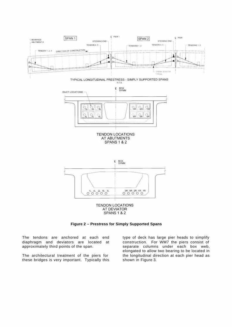
Figure 2 – Prestress for Simply Supported Spans The tendons are anchored at each end diaphragm and deviators are located at approximately third points of the span. The architectural treatment of the piers for these bridges is very important. Typically this
type of deck has large pier heads to simplify construction. For WM7 the piers consist of separate columns under each box web, elongated to allow two bearing to be located in the longitudinal direction at each pier head as shown in Figure 3.
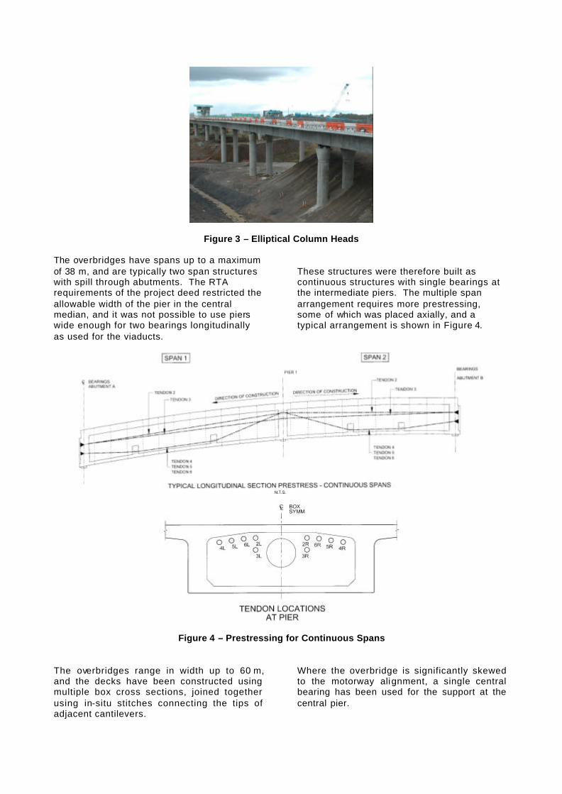
Figure 3 – Elliptical Column Heads The overbridges have spans up to a maximum of 38 m, and are typically two span structures with spill through abutments. The RTA requirements of the project deed restricted the allowable width of the pier in the central median, and it was not possible to use piers wide enough for two bearings longitudinally as used for the viaducts.
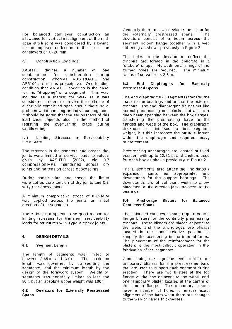
These structures were therefore built as continuous structures with single bearings at the intermediate piers. The multiple span arrangement requires more prestressing, some of which was placed axially, and a typical arrangement is shown in Figure 4.
Figure 4 – Prestressing for Continuous Spans The overbridges range in width up to 60 m, and the decks have been constructed using multiple box cross sections, joined together using in-situ stitches connecting the tips of adjacent cantilevers.
Where the overbridge is significantly skewed to the motorway alignment, a single central bearing has been used for the support at the central pier.

4.3 Balanced Cantilever The bridges erected using the balanced cantilevering method are prestressed using tendons internal to the concrete section. The joints between match cast segments in the completed structure are coated with epoxy. The balanced cantilever bridges are used for the longer spans over Old Windsor Road and Cowpasture Road, and for the curved ramps at the major motorway interchanges. Segments are erected by crane and temporarily connected using VSL stressbar. When corresponding segments have been erected on each end of the cantilever, permanent prestressing tendons are installed within the box top flange and tensioned from one end. Once the cantilevers are completed, a short in situ section connects the cantilevers followed by installation of continuity tendons stressed from blisters attached to the bottom flange. All prestress is internal to the section and fully grouted. Epoxy is used on the segments joints to ensure protection of the tendons. All stressing blisters for the continuity stressing and for the temporary erection bars are cast as part of the concrete box section. For the balanced cantilever bridges, the bottom flange thickness and web thickness both vary, which increased the complexity of the temporary blister arrangements. The shape of the piers varies depending on the site constraints. Typically the piers are single columns supported on a pilecap and bored piles. For all bridges other than the M4 ramps, temporary props supported on the pile caps resist the overturning of the cantilever during erection. For the M4 ramp bridges, which are much higher (up to 25 m above the existing), the stability is achieved by two sets of ties that are anchored in the pilecap. 5. DESIGN CRITERIA 5.1 Traffic Live Loads The project was commenced before the publication of AS5100 (2004), but the SWTC required traffic live loads that were in the draft codes and that have now been incorporated into the Australian Bridge Design Code AS5100 (2004). The traffic barrier loadings designed for are also those now incorporated into AS5100 (2004).
In addition, bridges were designed for construction loadings consisting of off-highway trucks, scrapers and concrete paver loadings. Traffic barrier loadings are also as now specified in AS5100. 5.2 Segmental Bridges Provisions The AUSTROADS (1992) Code was the nominated Bridge Design Code, but as there was considered to be a number of deficiencies and omissions in the AUSTROADS Code with respect to the design of precast segmental bridges, additional provisions generally based upon the AASHTO LRFD Bridge Design Specifications (2002) were incorporated into the design criteria used for the project. (i) Stress in Unbonded Tendons at Strength Ultimate Limit State The provisions of AASHTO (2002) were adopted. The provisions in AS5100 (2004) are now similar to these provisions. (ii) Shear at Segment Joints There is no provision in AUSTROADS or AS5100 for shear on segmental girder joints. For structures utilising dry joints (referred to as Type B joints), the provisions of AASHTO (2002) were adopted. (iii) Design for Torsion The AUSTROADS code does not apply for torsion of segmental box girders and so the provisions of AASHTO (2002) were thus used. Since the treatment of shear in AASHTO differs from that in AUSTROADS and AS5100, the AASHTO provisions for shear in combination with torsion were used. (iv) Construction Tolerances The AUSTROADS and AS5100 codes require the designer to consider construction forces and effects. For the precast segmental bridges, the following tolerances were adopted on the WM7 project. These values obviously depend on the methods adopted in the casting yard for controlling the match casting. For span-by -span girders made continuous, an allowance for a construction tolerance on alignment of +/- 15 mm in relative position of supports when the bridges is lowered onto the bearings;
For balanced cantilever construction an allowance for vertical misalignment at the mid-span stitch joint was considered by allowing for an imposed deflection of the tip of the cantilevers of +/- 20 mm (v) Construction Loadings AASHTO defines a number of load combinations for consideration during construction, whereas AUSTROADS and AS5100 are not as prescriptive. One loading condition that AASHTO specifies is the case for the “dropping” of a segment. This was included as a loading for WM7 as it was considered prudent to prevent the collapse of a partially comple ted span should there be a problem while handling an individual segment. It should be noted that the seriousness of this load case depends also on the method of resisting the overturning loads during cantilevering. (vi) Limiting Stresses at Serviceabilit y Limit State The stresses in the concrete and across the joints were limited at service loads to values given by AASHTO (2002), viz 0.7 compression MPa maintained across dry joints and no tension across epoxy joints. During construction load cases, the limits were set as zero tension at dry joints and 0.5 v( f’c ) for epoxy joints. A minimum compressive stress of 0.15 MPa was applied across the joints on initial erection of the segments. There does not appear to be good reason for limiting stresses for transient serviceability loads for structures with Type A epoxy joints. 6. DESIGN DETAILS 6.1 Segment Length The length of segments was limited to between 2.65 m and 3.0 m. The maximum length was governed by transporting the segments, and the minimum length by the design of the formwork system. Weight of segments was generally limited to less the 80 t, but an absolute upper weight was 100 t. 6.2 Deviators for Externally Prestressed Spans
Generally there are two deviators per span for the externally prestressed spans. The deviators consist of a beam across the segment bottom flange together with a web stiffening as shown previously in Figure 2. The holes in the deviator to deflect the tendons are formed in the concrete in a “diabolo” shape. No additional linings of the formed holes are required. The minimum radius of curvature is 3.8 m. 6.3 End Diaphragms for Externally Prestressed Spans The end diaphragms (E segments) transfer the loads to the bearings and anchor the external tendons. The end diaphragms do not act like normal prestressing end blocks, but act as a deep beam spanning between the box flanges, transferring the prestressing force to the flanges and webs of the box. The diaphragm thickness is minimised to limit segment weight, but this increases the strut/tie forces within the diaphragm and requires heavy reinforcement. Prestressing anchorages are located at fixed position, with up to 12/31 strand anchors used for each box as shown previously in Figure 2. The E segments also attach the link slabs / expansion joints as appropriate, and downstands for the support bearings. The downstands are of sufficient width to allow placement of the erection jacks adjacent to the bearings. 6.4 Anchorage Blisters for Balanced Cantilever Spans The balanced cantilever spans require bottom flange blisters for the continuity prestressing tendons. These blisters are placed adjacent to the webs and the anchorages are always located in the same relative position to simplify the positioning in the internal forms. The placement of the reinforcement for the blisters is the most difficult operation in the fabrication of the segments. Complicating the segments even further are temporary blisters for the prestressing bars that are used to support each segment during erection. There are two blisters at the top flange of the box adjacent to the webs, and one temporary blister located at the centre of the bottom flange. The temporary blisters have a number of holes to ensure exact alignment of the bars when there are changes to the web or flange thicknesses.

A cross section of a cantilever segment showing typical blister positions is given in
Figure 5.
Figure 5
6.5 Segment Reinforcement Arrangement In order to achieve high production rates in the precasting factory, the reinforcement has been simplified, having a minimum number of different shapes and sizes. The bars are arranged in sets of transverse bars, which are then fabricated into cages with a small number of longitudinal bars. The reinforcement slices are spaced at 200 mm centres for all segments. This was found to be an optimum spacing, and it allowed inserts for lifting, and temporary attachment s during construction to be placed between the slices. This spacing also allowed considerable flexibility is selection of bars sizes to minimise reinforcement quantities. 6.6 Handling of Segments All segments are handled on site using “Swiftlifts” cast into the segments within the line of the webs. In the precasting yard, the segments are lifted from beneath the cantilevers using purpose made straddle carriers. The design of the segments allowed for the handling of the segments at an early age. 6.7 Bridge Longitudinal Articulation Overbridges are fixed longitudinally at one end, which is generally the downhill side in order to minimise drainage across deck movement joints. Viaducts are fixed longitudinally at a number of locations, selected to optimise the number and size of expansion joints. Short ramps are fixed at one end, and longer ramps are fixed near the centre of the bridge and expansion joints are located at both ends.
6.8 Bearings Bearings are generally confined pot-type bearings. For vi aducts, elastomeric bearings were used where possible at piers where longitudinal movements were small and pot bearings elsewhere. The maximum bearing size was for a load of 1800 t (serviceability) for Old Windsor Road Bridge. 6.9 Transverse Prestressing Transverse prestressing in the form of slab anchors was used for wide boxes with cantilevers over 3.6 m. The transverse prestressing allowed early stripping on the cantilever forms (a small amount of prestress was applied after 12 hours). The transverse prestressing also controls deflections under service loads. 6.10 Balanced Cantilever Erection Design Vertical loads are always taken through the permanent bearings and the out-of-balance moments are taken through external props and ties. This erection philosophy minimises the construction load effects on the columns, although it does require care with setting and aligning the initial segments for each cantilever to ensure accurate alignment. For all balanced cantilever bridges except for the M4 ramps, concrete props are used at each of the piers to take the out-of-balance moments. For the M4 ramps, where piers are up to 25 m in height and where there was often very limited room at the pilecap level due to existing traffic, tension ties on each side of the
columns take the out -of-balance moments. The loads in the tension ties are increased in stages only as the longitudinal cantilevering prestress increases so as not to overload the webs adjacent to the piers. 6.11 Urban Design Considerations The RTA has place a great importance on the urban design of these major infrastructure works and this has been followed through with the selection of appropriate forms for bridges and design details. The slender box girders with long cantilevers have been considered to enhance the appearance of the bridges, particularly the highly visible overbridges. The column shapes and the abutment treatments have been selected to achieve a consistent family of bridges that will be readily
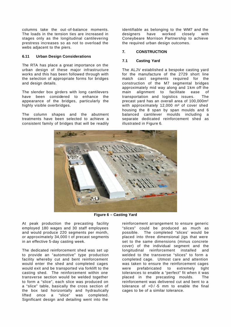
identifiable as belonging to the WM7 and the designers have worked closely with Coneybeare Morrison Partnership to achieve the required urban design outcomes. 7. CONSTRUCTION 7.1 Casting Yard The ALJV established a bespoke casting yard for the manufacture of the 2729 short line match cas t segments required for the construction of the M7 segmental bridges approximately mid way along and 1 km off the main alignment to facilitate ease of transportation and logistics issues. The precast yard has an overall area of 100,000m² with approximately 12,000 m² of cover shed housing the 8 span by span moulds and 6 balanced cantilever moulds including a separate dedicated reinforcement shed as illustrated in Figure 6.
Figure 6 – Casting Yard
At peak production the precasting facility employed 180 wages and 30 staff employees and would produce 220 segments per month, or approximately 34,000 t of precast segments in an effective 5-day casting week. The dedicated reinforcement shed was set up to provide an “automotive” type production facility whereby cut and bent reinforcement would enter the shed and completed cages would exit and be transported via forklift to the casting shed. The reinforcement within one transverse section would be welded together to form a “slice”, each slice was produced on a “slice” table, basically the cross section of the box laid horizontally and hydraulically lifted once a “slice” was completed. Significant design and detailing went into the
reinforcement arrangement to ensure generic “slices” could be produced as much as possible. The completed “slices’ would be placed into three dimensional jigs that were set to the same dimensions (minus concrete cover) of the individual segment and the longitudinal reinforcement installed and welded to the transverse “slices” to form a completed cage. Utmost care and attention was taken to ensure the reinforcement cages were prefabricated to extremely tight tolerances to enable a “perfect” fit when it was placed in the precasting moulds. The reinforcement was delivered cut and bent to a tolerance of +0 / -5 mm to enable the final cages to be of a similar tolerance.

Once the reinforcement cage for an individual segment was completed it will be transported to the required short line match cast mould. The term “short line” is used to descript the process were by one individual segment is cast against it’s adjacent segment within the structure, the then completed segment is moved out to enable the next segment to be cast, with the formwork remaining “static”, as opposed to “long line” casting whereby the formwork moves and the segments remain static. Utilising the short line matching casting method, 50 to 55 segments per week were produced from the 14 moulds in a 5 day casting week, effectively casting 11 of the 14 segments on a “daily turn around”
The daily cycle relied on a concrete strength gain of 12 MPa in 12 hrs to enable the forms to be demoulded 12 hrs after casting and providing a 12 hr window to demould, clean, place reinforcement, seal, inspect the mould and place concrete. This however, for the standard / typical segments could be completed in a standard 8 hr shift once the “learning curve” was completed. A typical segment casting week would generate 130 man hours per segment including indirect labour, reinforcement, finishing and handling. Once the segments were cast they were transported to the storage yard by bespoke straddle carriers, designed and imported from Italy, with hydraulic operated lifting frames that did not require labour to access the top of the segment thus avoiding unnecessary OH&S issues, see Figure 7.
Figure 7 – Straddle Carrier At peak we had approximately 525 segments in storage Upon completion of a minimum “curing” period and strength requirements, and any remedial or finishing works the segments are transported to site for installation. 7.2 Segment Erection The installation of the segments is carried out using one of three methods; span-by span using gantries, continuous span-by -span supported on falsework, or balanced cantilever.
(i) Span by Span using Gantry (simply supported viaducts) This method utilises an underslung self launching gantry, as illus trated in Figure 8, to support the specified segments within a span, nominally 10 to 12 segments for span lengths in the range of 35 to 38m in length. After erection of the segments, the external post tensioned tendons are installed and stressed from the leading edge (generally four to six pairs of 31/15.2 mm strand tendons). The underslung gantry was supplied by VSL Australia as part of the Alliance Works undertaken by VSL and ALJV for the installation of the segments.

Figure 8 – Gantry for Span by Span Bridges
Once the minimum self-supporting tendons are stressed (nominally 50% of the total prestress force) the segments are lowed onto span jacks to enable the gantry to be launched forward to the next span to start the cycle over. Generally a 38 m span can be completed in 2.5 days utilising 35 man hours per segment. Of the 2729 segments, 878 (32%) are installed utilising this method for six separate bridge structures. (ii) Span by Span on Falsework (continuous overbridges) This method utilises a more traditional falsework or scaffold system made up of RMD components and in-house designed structure steelwork head beams and end span supports. Bridges constructed in this manner are generally the overbridges to the WM7 and are either 2, 3 or 4 span continuous structures whereby the external prestressing tendons run the full length of the structure. Generally a 65 m two span continuous structure can be completed in 2 weeks utilising 38 man hours per segment. (iii) Balanced Cantilever This method is used for the longer and more irregular span lengths and is best suited to
structures with spans over 50 m. Our most dramatic structures are constructed using this method, such as the Old Windsor Road crossing which has a main span of 94 m and the Light Horse Interchange at the M4 were the approach and exit ramps are some 28 m above the existing M4 in several “layers” with variable span lengths of up to 52.5 m. Once completed, the Light Horse Interchange will be the largest interchange in the Southern Hemisphere. The balanced cantilever method requires the central pier segment to be placed directly over the pier / column and supported off a temporary works platform. Once the segment is aligned in three dimensions the pot bearings are grouted and the pier segment is stressed down to the pier / column via temporary bars. Once the pier segment is “stabilised” the span or field segments are installed in an “up chainage down chainage” manner hence keeping the system in “balance”. Upon completion of the eac h “up chainage down chainage” pair of segments, permanent internal stressing is installed and the process repeated until a half cantilever is complete, as demonstrated in Figure 9. 988 (36%) of the 2729 segments are installed utilising this method for 12 separate bridge structures.
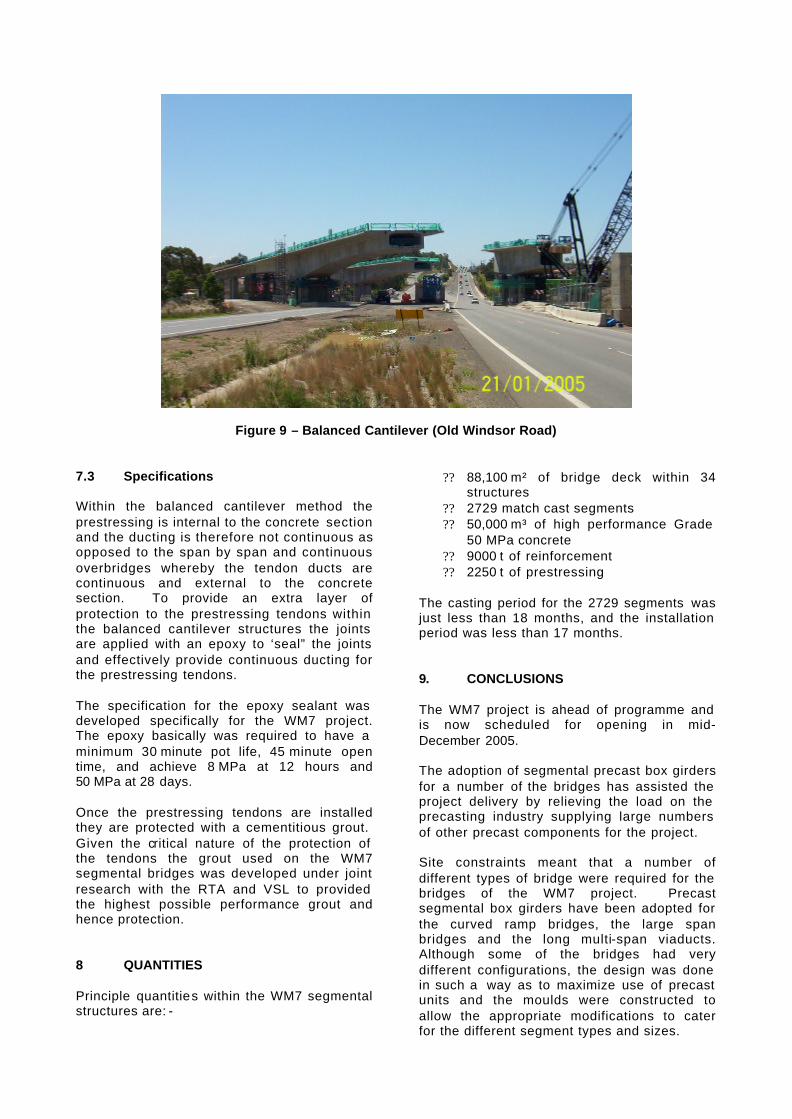
Figure 9 – Balanced Cantilever (Old Windsor Road) 7.3 Specifications Within the balanced cantilever method the prestressing is internal to the concrete section and the ducting is therefore not continuous as opposed to the span by span and continuous overbridges whereby the tendon ducts are continuous and external to the concrete section. To provide an extra layer of protection to the prestressing tendons within the balanced cantilever structures the joints are applied with an epoxy to ‘seal” the joints and effectively provide continuous ducting for the prestressing tendons. The specification for the epoxy sealant was developed specifically for the WM7 project. The epoxy basically was required to have a minimum 30 minute pot life, 45 minute open time, and achieve 8 MPa at 12 hours and 50 MPa at 28 days. Once the prestressing tendons are installed they are protected with a cementitious grout. Given the critical nature of the protection of the tendons the grout used on the WM7 segmental bridges was developed under joint research with the RTA and VSL to provided the highest possible performance grout and hence protection. 8 QUANTITIES Principle quantities within the WM7 segmental structures are: -
?? 88,100 m² of bridge deck within 34 structures
?? 2729 match cast segments ?? 50,000 m³ of high performance Grade
50 MPa concrete ?? 9000 t of reinforcement ?? 2250 t of prestressing
The casting period for the 2729 segments was just less than 18 months, and the installation period was less than 17 months. 9. CONCLUSIONS The WM7 project is ahead of programme and is now scheduled for opening in mid-December 2005. The adoption of segmental precast box girders for a number of the bridges has assisted the project delivery by relieving the load on the precasting industry supplying large numbers of other precast components for the project. Site constraints meant that a number of different types of bridge were required for the bridges of the WM7 project. Precast segmental box girders have been adopted for the curved ramp bridges, the large span bridges and the long multi-span viaducts. Although some of the bridges had very different configurations, the design was done in such a way as to maximize use of precast units and the moulds were constructed to allow the appropriate modifications to cater for the different segment types and sizes.

The design of the segment box girder bridges for this project required development of additional design criteria for aspects not fully covered in current Australian codes. These criteria could be used as the basis for future similar projects. Construction A purpose built PC factory was established for the project and 2703 segments were produced using short line precasting techniques. Different site constraints dictated that erection of segments was by three methods (i) span by span on erection girders
(ii) span by span on falsework and (iii) balanced cantilevering, and each was successfully implemented on this project. References AUSTROADS (1992). Bridge Design Code, AUSTROADS, Sydney Standards Australia. (2004). Australian Standard. Bridge Design. Standards Australia International, Sydney, AS 5100. AASHTO (2002), AASHTO LRFD Bridge Design Specifications