Solution Processable OLEDs -...
31
Solution Processable OLEDs Merck KGaA Merck KGaA Anna Hayer EuroDisplay 2013 16/09/2013
Transcript of Solution Processable OLEDs -...

Solution Processable OLEDs
Merck KGaAMerck KGaAAnna Hayer
EuroDisplay 2013
16/09/2013

Content
1 Introduction
2 OLED Basics
EuroDisplay 2013 – Hayer - Merck – Solution Processable OLEDs2 16/09/2013
3 Challenges for Solution Processing
4 Current Results
5 Summary

Why OLED?
ultra-thin & light-weight high contrast / true blackwide viewing angle
fast switching
high energy efficiency
EuroDisplay 2013 – Hayer - Merck – Solution Processable OLEDs3 16/09/2013
large area
flat light source
fast switching
new design opportunities
� arbitrary 2D shape
� flexible
� transparent

Why solution-processing?
already in mass productionoffer the advantages of
� greater ease of processing
� reduced manufacturing costs
evaporation-based OLEDs solution-processed OLEDs
EuroDisplay 2013 – Hayer - Merck – Solution Processable OLEDs
� reduced manufacturing costs
� very large area application
� variety of processing techniques available
4 16/09/2013

= Light Modulation
Liquid Crystal
= Light Generation
Organic Light Emitting Diode
OLED: What is the buzz about?
OLED: A fully controllable light bulb with the correct colour in every pixel.
3 – 6 V
Back Light Back Light
EuroDisplay 2013 – Hayer - Merck – Solution Processable OLEDs5 16/09/2013

Content
1 Introduction
2 OLED Basics
EuroDisplay 2013 – Hayer - Merck – Solution Processable OLEDs6 16/09/2013
3 Challenges for Solution Processing
4 Current Results
5 Summary

-LUMO
EF
Working principle of simple OLEDs
3 –
6 V
EuroDisplay 2013 – Hayer - Merck – Solution Processable OLEDs
HOMO+
eU
EF
Anode CathodeEmissive Layer
7 16/09/2013
Anode CathodeEmissive Layer

Device setup: Simple stack
� Basic Processes
– Charge injection (1)
– Charge transport (2)
– Exciton formation (3)
21
3
hν
EuroDisplay 2013 – Hayer - Merck – Solution Processable OLEDs
– Recombination (4)
� Drawbacks of single layer device
– Large injection barriers
– Holes und electrons not balanced
– Leakage current
Anode CathodeEmissive layer
(EML)
1 2
3
hν 4
8 16/09/2013

Device setup: Improved stack
Improvements via multilayer:
� Additional injection layer
– Lower voltage
2
1
3
hν 4
EuroDisplay 2013 – Hayer - Merck – Solution Processable OLEDs
� Additional blocking layer
– Reduced leakage
� Specialization of materials
– High mobilities
– High quantum efficienciesAnode CathodeEML
12
3
4
ETLHTL
Electron
injection
layer
(EIL)
Hole
injection
layer
(HIL)
9 16/09/2013

OLED characterisation: Initial performance
apply drive voltage; increase in steps
measure current measure brightness measure spectrum
0.001
0.01
0.1
1
10
100
curr
en
t de
nsi
ty [m
A/c
m²]
0.4
0.6
0.8
1
1.2
EL
no
rm.
[arb
. un
its]
100
1000
10000
100000
lum
ina
nce
[cd
/m²]
EuroDisplay 2013 – Hayer - Merck – Solution Processable OLEDs10
calculate efficiency in
� EQE � photons per electron
� cd/A � visible light per current
� lm/W � optical power per
electrical power
calculate colour coordinatesCIEx, CIEy
0.000001
0.00001
0.0001
0 5 10
curr
en
t de
nsi
ty [m
A/c
m²]
voltage [V]
0
10
20
30
40
50
60
70
80
0 2000 4000
eff
icie
ncy
[cd
/A]
luminance [cd/m²]
460
470
480
490
520
530
540
550
560
570
580
590
600
610
630680
0
0.1
0.2
0.3
0.4
0.5
0.6
0.7
0.8
0.9
0 0.5
Y
X
0
0.2
0.4
400 500 600 700 800
EL
no
rm.
[arb
. un
its]
wavelength [nm]
1
10
0 5 10lu
min
an
ce [c
d/m
²]voltage [V]
16/09/2013

OLED characterisation: Long term stability
apply constant current
measure light output over time measure voltage increase over time
6000
8000
10000
12000
lum
ina
nce
[cd
/m²]
3
4
5
6
vo
lta
ge
[V]
EuroDisplay 2013 – Hayer - Merck – Solution Processable OLEDs11
0
2000
4000
6000
0 200 400 600 800
lum
ina
nce
[cd
/m²]
time [h]
0
1
2
3
0 200 400 600 800
vo
lta
ge
[V]
time [h]
Lifetime LT50 :
time until the brightness is reduced to 50%
LT80, LT95, LT97 etc. accordingly
16/09/2013

OLED Discovery
1987:
Tang & van Slyke
@Eastman Kodak
OLED from evaporated small molecules
1990:
Burroughes, Bradley, Brown, Marks,
Mackay, Friend, Burn, Holmes
@University of Cambridge
polymer OLED from solution-processed precursor
EuroDisplay 2013 – Hayer - Merck – Solution Processable OLEDs12 16/09/2013

OLED preparation: Vacuum evaporation
SubstrateCathode
separator
RGB Pixels
EuroDisplay 2013 – Hayer - Merck – Solution Processable OLEDs
Source Shadow Mask
13 16/09/2013
Advantages:
� already in mass production
� high performance
� easy fabrication of multilayer stacks
Drawbacks:
� relatively low material utilisation
� scaling to very large areas challenging
(fine metal masks, ...)

OLED preparation: Solution Processing
Already in mass production in LC industry:
Inkjet printing Examples: other printing methods
EuroDisplay 2013 – Hayer - Merck – Solution Processable OLEDs14 16/09/2013
Already in mass production in LC industry:
� used for colour filters
� up to Gen 8 (glass size : ~ 2.2 x 2.5 m²)
� to be adapted to functional layers
gravure printing flexographic printing
slot die coating(unstructured, for wide area)
Spin-coating
� Fast and easy process� ideal for material evaluation
� unstructured � not for polychrome displays
Content
1 Introduction
2 OLED Basics
EuroDisplay 2013 – Hayer - Merck – Solution Processable OLEDs15 16/09/2013
3 Challenges for Solution Processing
4 Current Results
5 Summary

Solubility
standard evaporable material:
not soluble
Examples for low solubility in common
organic solvents:
N
N
N
Ir
3
Ir(ppy)3
a green emitterNPB
a hole transport material
EuroDisplay 2013 – Hayer - Merck – Solution Processable OLEDs16
soluble OLED material
N
N
N
*
*n
16/09/2013
octyl-NPB TFB
one approach to solubilise:
long alkyl chains
often purely aromatic compounds

Film Formation
What is needed
� during coating:
� low aggregation & crystallisation
tendency
� low phase separation
Examples: What it should not look like
EuroDisplay 2013 – Hayer - Merck – Solution Processable OLEDs17
� low phase separation
(in a mixture)
� good wetting
� during solvent removal:
� high glass transition temperature
� low aggregation & crystallisation
tendency
16/09/2013
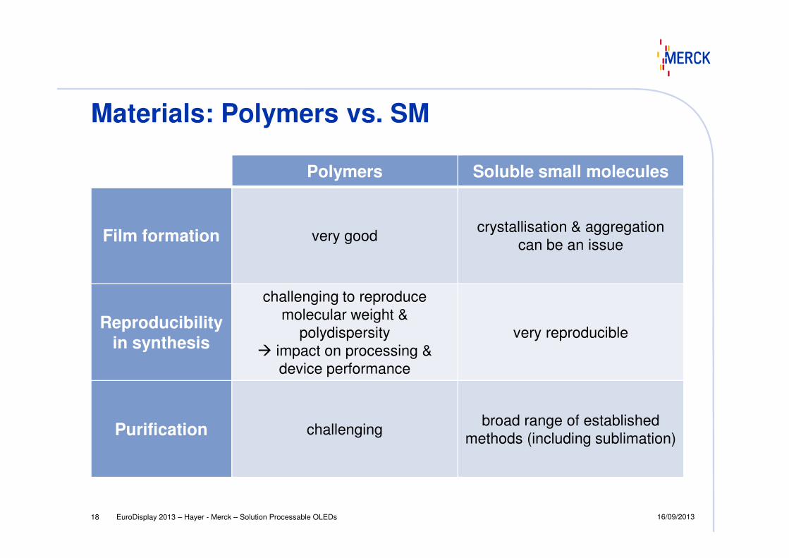
Materials: Polymers vs. SM
Polymers Soluble small molecules
Film formation very goodcrystallisation & aggregation
can be an issue
Reproducibilityin synthesis
challenging to reproduce
molecular weight &
polydispersity
� impact on processing &
device performance
very reproducible
Purification challengingbroad range of established
methods (including sublimation)
EuroDisplay 2013 – Hayer - Merck – Solution Processable OLEDs18 16/09/2013

Multilayer from solution: ChallengeCathode
ETL
EML
HTL
ITO
EML
HTL
ITO
HTL
ITO
achieve achieve
Avoid washing off or redisolving previous layer during deposition of next layer
EuroDisplay 2013 – Hayer - Merck – Solution Processable OLEDs19 16/09/2013
EML
ITO
EML/HTL
ITO
EML
ITO
avoid
avoid
ETL/EML/HTL
ITO
washed off reduced mixed mixed

Multilayer approaches: Orthogonal solvents
ETL
EML
HTL
ITO
EML
HTL
ITO
HTL
ITO
EuroDisplay 2013 – Hayer - Merck – Solution Processable OLEDs20
ITOITOITO
first layer
from water
second layer
from organic solvent (e.g. xylene)
third layer
from alcohol (e.g. methanol)
example:
PEDOT/PSS PFO PFON+(CH3)3I--PBD
Ma et al., Adv.Mat. 2005, 17, 274
* *n
O
N N
NN
* *n
+
+I-
I-OO
S* *n
**
n
SO3-

Multilayer approaches: Cross-linking
ETL
EML
ITO
EML
ITOdeposition of first
curing next layer can be
hν or ∆T
photoinitiator,
RT
EuroDisplay 2013 – Hayer - Merck – Solution Processable OLEDs21 16/09/2013
example: Du et al., Macromol. Rapid
Commun. 2006, 27, 412:
O
Al
N
O
O
O
O
N
O
OO
O
N
OO
O
N
Al
O
N
AlO
N Al
O
O
Al
NO
N
O
N
n
m
l
for a review, see
Zuniga et al., Chem.Mat. 2011, 23, 658
ITOdeposition of first
layer from solution
curing
� polymerisation
� layer becomes insoluble
next layer can be
deposited from solution (even from same solvent)

Content
1 Introduction
2 OLED Basics
EuroDisplay 2013 – Hayer - Merck – Solution Processable OLEDs22 16/09/2013
3 Challenges for Solution Processing
4 Current Results
5 Summary
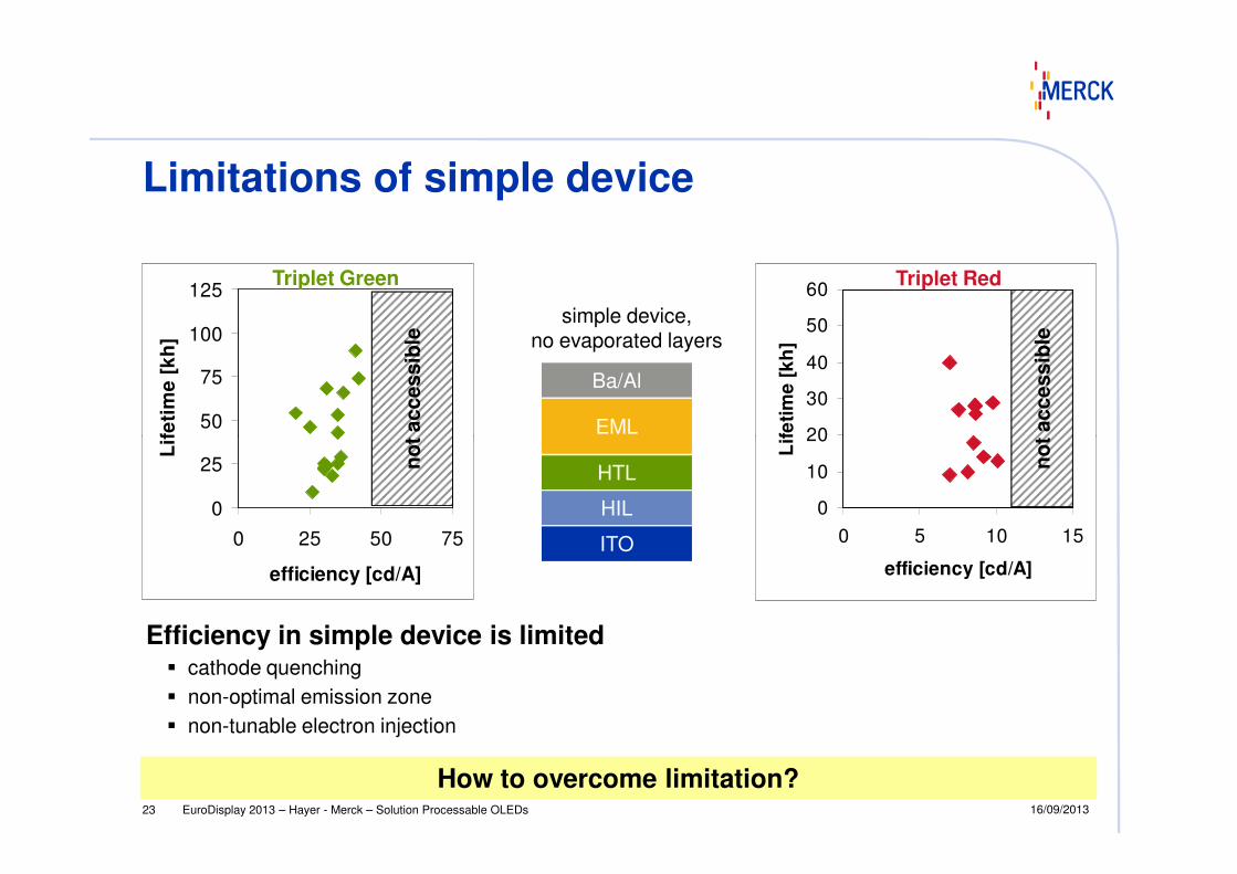
Limitations of simple device
50
75
100
125
Lif
eti
me
[k
h]
Triplet Green
no
t accessib
le20
30
40
50
60
Lif
eti
me
[k
h]
Triplet Red
no
t accessib
le
Ba/Al
EML
simple device,no evaporated layers
EuroDisplay 2013 – Hayer - Merck – Solution Processable OLEDs23
Efficiency in simple device is limited� cathode quenching
� non-optimal emission zone
� non-tunable electron injection
How to overcome limitation?
0
25
0 25 50 75
efficiency [cd/A]
Lif
eti
me
[k
h]
no
t accessib
le
0
10
20
0 5 10 15
efficiency [cd/A]
Lif
eti
me
[k
h]
no
t accessib
le
EML
HTL
HIL
ITO
16/09/2013

Evaporated layers for higher efficiency
Ba/Al
EML
IL
Al
ETL
HBL
EML0
2
4
6
8
10
12
14
0 5000
EQ
E [
%]
evaporated
solution-processed
RED
EuroDisplay 2013 – Hayer - Merck – Solution Processable OLEDs24
IL
Buffer
ITO
EML
HTL
HIL
ITO
0 5000
luminance [cd/m²]
Evaporated layers improve efficiency by ca. 40%
solution-processed
Introduce evaporated HBL + ETL to overcome
efficiency limit
processed
0
2
4
6
8
10
12
14
16
0 5000
EQ
E [
%]
luminance [cd/m²]
GREEN
16/09/2013

Hybrid device for high efficiency
30
40
50
60
Lif
eti
me
[k
h] simple device
with ETL
Triplet GreenTriplet Red
75
100
125
150
Lif
eti
me
[k
h]
simple device
with ETL
Ba/Al
EML
IL
Buffer
ITO
solution-processed
EuroDisplay 2013 – Hayer - Merck – Solution Processable OLEDs25
With ETL: Efficiency limitation overcome
0
10
20
30
0 5 10 15
efficiency [cd/A]
Lif
eti
me
[k
h]
0
25
50
75
0 25 50 75
efficiency [cd/A]
Lif
eti
me
[k
h]
16/09/2013
Al
ETL
HBL
EML
HTL
HIL
ITO
evaporated
solution-processed

Al
ETL
HBL
EML
Performance progess via material and stack optimisation
150
200
250
300
350
LT
50
[k
h]@
10
00
cd
/m² with ETL
evaporated
solution-
HTL
HIL
ITO
EuroDisplay 2013 – Hayer - Merck – Solution Processable OLEDs26
With optimised materials: strong increase in lifetime as well as efficiency
0
50
100
150
0 25 50 75
LT
50
[k
h]@
10
00
cd
/m²
eff. [cd/A]@1000 cd/m²
simple device
� improved materials
� optimised material combinations
� adapted layer thickness
16/09/2013
solution-processed

� high
� low
amount ofh-transporting
Example: Mixture optimisation
10%
15%
20%
25%
EQ
E
LT8
0
more
h
In this case, both efficiency & lifetime increase when balance is tuned towards more holes
���� initial mix was much too electron-dominated
h-transporting component
EML mixture with 3 components:
� electron-transporting host
� co-host
� triplet emitter
Balance optimisation: how much
� electron-transporting
� hole-transporting
component is needed for best performance?
EuroDisplay 2013 – Hayer - Merck – Solution Processable OLEDsh27 16/09/2013
0%
5%
e-transporting component e-transporting component
more emore e
In this case, both efficiency & lifetime increase when balance is tuned towards more holes
���� initial mix was much too electron-dominated

0.1
1
10
100
1000
cu
rre
nt d
en
sity [
mA
/cm
²]
More h-injecting HTL for high lifetime
9000
9500
10000
lum
ina
nce
[cd
/m²]
HTL 1HTL 2HTL 3
bipolar device
HTL 1
1E-3
0.01
0.1
0 2 4 6
cu
rre
nt d
en
sity [
mA
/cm
²]
voltage [V]
8000
8500
0 200 400 600 800 1000
lum
ina
nce
[cd
/m²]
time [h]
If hole transport is so important for this mixture:
Improve best mix even further by also increasing hole injection
EuroDisplay 2013 – Hayer - Merck – Solution Processable OLEDs28 16/09/2013
hole-only device
HTL 1HTL 2HTL 3
With new HTL: 300 000h lifetime achieved
>900h @ 10 000 cd/m²
� 300 000h @ 1 000 cd/m²

Content
1 Introduction
2 OLED Basics
EuroDisplay 2013 – Hayer - Merck – Solution Processable OLEDs29 16/09/2013
3 Challenges for Solution Processing
4 Current Results
5 Summary

Conclusion
� OLEDs for ultra-thin lighting tiles and displays with wide viewing
angle, high efficiency & contrast and new design opportunities
� solution-processing for very large area applications, greater ease
of processing and reduced manufacturing costs
� key parameters for solution processing: � key parameters for solution processing:
solubility & film formation
� multilayer OLED stacks from solution:
e.g. via use of orthogonal solvents or via cross-linking
� high efficiency in solution-processed OLED achieved with
evaporated ETL
� improved materials, optimised material combinations and adapted
layer thickness for very high performance:
300 000h lifetime and 80cd/A / 21% EQE in soluble green
EuroDisplay 2013 – Hayer - Merck – Solution Processable OLEDs30 16/09/2013
ETL/
EML/HTL
ITO
0
50
100
150
200
250
300
350
0 25 50 75
LT
50 [
kh
]@1000 c
d/m
²
eff. [cd/A]@1000 cd/m²
simple
device
with ETL
0
25
50
75
100
125
150
0 25 50 75
efficiency [cd/A]
Lif
eti
me
[k
h]
simple device
with ETL

EuroDisplay 2013 – Hayer - Merck – Solution Processable OLEDs31 16/09/2013