SOLUTION OF CONFINED SEEPAGE PROBLEMS BELOW …
13
NIJOTECH VOL. 9 NO. 1 SEPTEMBER 1985 RAO 55 SOLUTION OF CONFINED SEEPAGE PROBLEMS BELOW HYDRAULIC STRUCTURES BY FINITE ELEMENT METHOD By L. H. Rao Department of Civil Engineering University of Nigeria, Nsukka (Manuscript received April, 1985) ABSTRACT Confined seepage problems below hydraulic structures using finite element method are investigated. The foundations are assumed to be infinite with homogeneous and isotropic conditions. Three different types of elements with varying mesh sizes are used for comparing the finite element results with those of exact solutions for simple boundary configurations. Iso- parametric quadrilateral elements which are best suited for inclined boundaries are used for solving the seepage problem beneath practical profiles of complicated boundary forms. The numerical results obtained are compared with those from experimental and other methods. 1. INTRODUCTION The study of flow through porous media has a wide range of applications in many facets of water resources management. The problem of confined seepage below river diversion and control structures resting on permeable foundations is one of the major problems of practical importance in this regard. Seepage of water below such structures has an important bearing on the stability of structures. Consequently the design of control structures founded on porous media necessitates an accurate prediction of the effect of seepage on the stability of the structures. The analysis of the problem must satisfy the dual criteria of keeping the residual pressures and the exit gradient within reasonable limits and at the same time effecting overall economy. The solution of confined seepage becomes involved in cases of complex profiles of the structure or where the permeable foundation is non-homogeneous or anisotropic. Hence the above problem has been the subject of several investigations in the past by experimental, empirical, analytical and approximate methods. In many practical problems the degree of heterogeneity, the nature of anisotropy and the complexity of boundary form encountered are such that the traditional analytical methods are extremely difficult to apply unless certain simplifying and unrealistic assumptions are made. These difficulties have lead to the development of numerical methods such as relaxation method, finite difference method and finite element method which are capable of taking into account all complexities generally observed in the solution of boundary value problems. Out of the two important numerical methods, i.e. finite difference and finite element method finite element is preferred to finite difference method because of latter's ineffectiveness in treating non-homogeneous material properties and complicated boundary conditions including irregular shapes. The present study therefore envisages the use of finite element technique for solving two-dimensional problems of confined seepage, below hydraulic structures with particular reference to media and complecity of boundary form of the structure. Optimum number of constant grade triangular elements, four mode rectangular elements and four node is oparametric elements are used for obtaining accurate results and compared with the exact or analytical solutions, wherever available. The investigations conducted are done in parts. Firstly to verify the accuracy of this method, finite
Transcript of SOLUTION OF CONFINED SEEPAGE PROBLEMS BELOW …

NIJOTECH VOL. 9 NO. 1 SEPTEMBER 1985 RAO 55
SOLUTION OF CONFINED SEEPAGE PROBLEMS BELOW
HYDRAULIC STRUCTURES BY FINITE ELEMENT METHOD
By
L. H. Rao
Department of Civil Engineering
University of Nigeria, Nsukka
(Manuscript received April, 1985)
ABSTRACT
Confined seepage problems below hydraulic structures using finite
element method are investigated. The foundations are assumed to be infinite
with homogeneous and isotropic conditions. Three different types of elements
with varying mesh sizes are used for comparing the finite element results
with those of exact solutions for simple boundary configurations. Iso-
parametric quadrilateral elements which are best suited for inclined
boundaries are used for solving the seepage problem beneath practical
profiles of complicated boundary forms. The numerical results obtained are
compared with those from experimental and other methods.
1. INTRODUCTION
The study of flow through porous
media has a wide range of
applications in many facets of water
resources management. The problem of
confined seepage below river
diversion and control structures
resting on permeable foundations is
one of the major problems of
practical importance in this regard.
Seepage of water below such
structures has an important bearing
on the stability of structures.
Consequently the design of control
structures founded on porous media
necessitates an accurate prediction
of the effect of seepage on the
stability of the structures.
The analysis of the problem must
satisfy the dual criteria of keeping
the residual pressures and the exit
gradient within reasonable limits and
at the same time effecting overall
economy. The solution of confined
seepage becomes involved in cases of
complex profiles of the structure or
where the permeable foundation is
non-homogeneous or anisotropic. Hence
the above problem has been the
subject of several investigations in
the past by experimental, empirical,
analytical and approximate methods.
In many practical problems the
degree of heterogeneity, the nature
of anisotropy and the complexity of
boundary form encountered are such
that the traditional analytical
methods are extremely difficult to
apply unless certain simplifying and
unrealistic assumptions are made.
These difficulties have lead to the
development of numerical methods such
as relaxation method, finite
difference method and finite element
method which are capable of taking
into account all complexities
generally observed in the solution of
boundary value problems. Out of the
two important numerical methods, i.e.
finite difference and finite element
method finite element is preferred to
finite difference method because of
latter's ineffectiveness in treating
non-homogeneous material properties
and complicated boundary conditions
including irregular shapes.
The present study therefore
envisages the use of finite element
technique for solving two-dimensional
problems of confined seepage, below
hydraulic structures with particular
reference to media and complecity of
boundary form of the structure.
Optimum number of constant grade
triangular elements, four mode
rectangular elements and four node is
oparametric elements are used for
obtaining accurate results and
compared with the exact or analytical
solutions, wherever available.
The investigations conducted are done
in parts. Firstly to verify the
accuracy of this method, finite

NIJOTECH VOL. 9 NO. 1 SEPTEMBER 1985 RAO 56
element results obtained, are
compared with those results obtained
by exact solutions for the case of
standard profiles like, horizontal
floor with a central pile and floor
with two piles. Finally using the
optimum number of elements thus
evolved, complicated boundary forms
of hydraulic structures are
considered for the solution of
confined seepage below the
structures. The results are based on
the computer programs especially
developed, using three different type
of elements with any boundary farm
and material properties for practical
profiles of the hydraulic structures.
2. REVIEW OF APPLICATION OF FINITE
ELEMENT METHOD TO SEEPAGE PROBLEMS
Zienkiewicz and Cheaung [1]
presented a numerical procedure for
dealing with boundary value field
problems based on their paper
presented at British theoretical
mechanics conference, Leeds, 1965.
The method, based on finite element
procedure adopts minimisation of an
appropriate functional for solution
of field problems like seepage, heat
conduction and torsion with the help
of a general computer program. This
investigation demonstrated the field
of applicability of finite element
procedure to areas other than
structural mechanics and has become a
general numerical method of wide'
applicability to problems of
engineering and physical science.
Zienkiewicz et al [2] have
presented through the finite element
method a numerical solution to the
governing equations of seepage flow
in non-homogeneous anisotropic media.
The formulation is developed in a two
dimensional situation using
triangular elements of arbitrary
shape. The solution thus obtained was
tested with the available results
from the exact solution and the
accuracy obtained was excellent. Even
though the investigation clearly
brought forward the versatile nature
of finite element method to deal with
arbitrary anisotropic problems, the
other type of element and complex
boundary forms are worthy of being
investigated.
Many other investigators using
the finite element procedure studied
the conditions of seepage flow under
free surface flow [3, 4, 5] and
unconfined flow situations [6]. It
may be seen from the above discussion
and references, the studies are
limited and generally pertain to
rather simple situations either in
terms of boundary forms or foundation
conditions. Further the different
types of element configurations have
not been studied in detail for
confined seepage problems.
3 BASIC EQUATIONS
The basic equation for flow
through porous media, combining
Darcy's law of seepage and the
continuity equation can be written as
follows:
(
)
(
)
(
)
……….. (1)
where kx ky kz are values of
coefficient of permeabilities in
three mutually perpendicular
directions and ( ) being the
piezometric head. For the case of two
dimensional flow in homogeneous
isotropic medium the eqn (1) is
further reduced to
It is evident from the above that the
problem of confined seepage boils
down to one of solving Inq the
Lapitace’s equation (2) by numerical
formulation using finite element
technique.
Applying Euler's equations of
variation for the two dimensional
problem under consideration, the
variational formulation for case of
non-homogeneous steady confined flow
can given by:
(
)
(
)
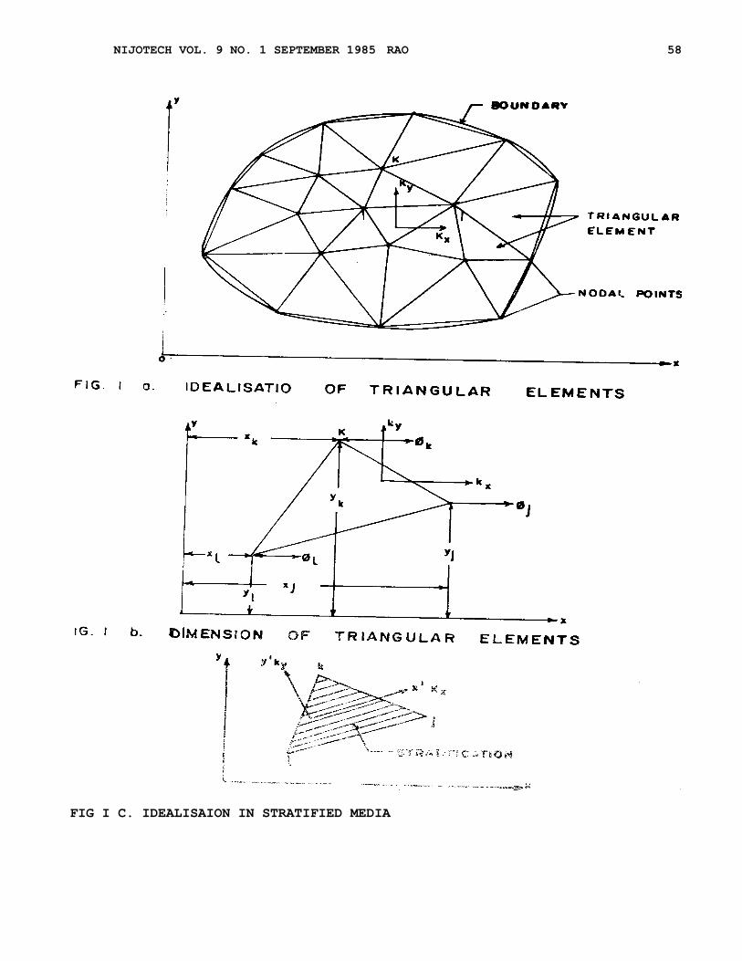
4. FINITE ELEMENT FORMULATION
The continuum is divided into an

NIJOTECH VOL. 9 NO. 1 SEPTEMBER 1985 RAO 57
equivalent system of finite for any
regular geometrical shape i.e.
triangle, rectangle quadrilateral
etc. as shown in Fig. 1 to 3 to suit
the boundary shape. The elements are
fixed in shape and do not change in
size or shape while the fluid seeps
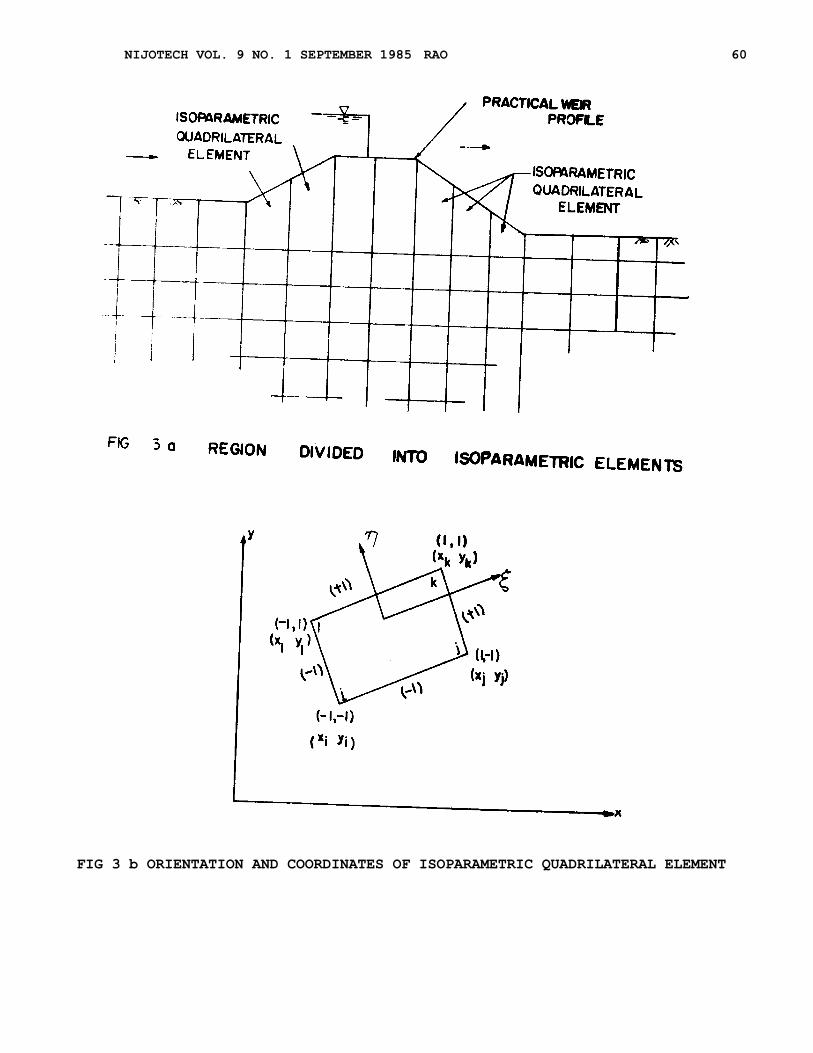
through them. As triangular or
rectangular element cannot represent
truly the curvilinear boundaries of
the continua, iso-parametric
quadrilateral element is considered
in such cases as shown in Fig. 3. The
field variable model selected to
represent the variation of the
unknown over each element is of
polynomial form e. g.
After selecting typical finite
element and the field variable model,
the derivation of the inite element
equations can be achieved by
variational methods. The solution of
the governing equation for two
dimensional seepage is mathematically
equivalent to finding a function
I( ), minimising the functional in
equation (3). Taken over the whole
region. The resulting property matrix
consisting of potential and the
permeability of the medium
K and the coordinates of the element
under consideration generally known
as seepage matrix is given by
]{ }
Where [S] is element seepage matrix
Once the individual seepage matrix is
found the contribution from all the
elements of the region are added
together to form overall seepage
matrix of the form
]{ } where [K] is the overall seepage
matrix and represent
potentials (percent of head acting)
at the individual nodal points. After
overall seepage matrix is formed
rest. of the procedure is simple
following the typical solution of
equations after substituting the
necessary boundary conditions.
5. IDEALISATION FOR FINITE ELEMENT
MESH
In numerical, experimental and
anolog techniques it is very
essential to simulate reservoir
boundaries and the depth of the
continuum (7, 8] such that the errors
in the unknowns will be as small as
possible when compared with the exact
solutions. The above factors are
directly involved in the
consideration of the finite element
mesh. Hence the model length and
depth are kept such that the error in
the seepage discharge is as small
as possib1e (1 percent) as the other
values (residual head, exit gradient)
are not much effected due to
variation in the idealised length of
the boundaries.
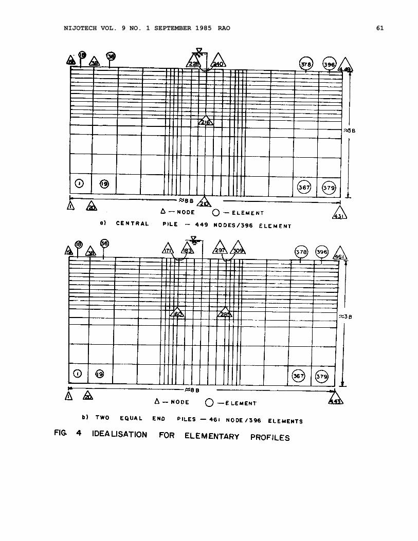
Therefore to kept the errors
within the above limits, the total
length of the reservoir boundary
should not be less than 2.SB on
either side of the floor and the
depth of the foundations should not
be less than 2.5B or 3S (whichever is
more) where B is the breadth of the
hydraulic structure and S is the
maximum pile depth. Finite depth
conditions can be incorporated easily
from the above. Based on the above
factors, a mesh size of BB x 3B is
adopted as shown in Figs. 4 to 6.
Different mesh sizes are adopted
for each type of element i.e.
triangular, rectangular and is
operametric guadrilateral element
adopting in each case a finer mesh in
the region where rapid variation is
expected. The results in each case
are compared with the exact solution
to identify the optimum conditions of
the mesh idealisation for maximum
accuracy.
As already emphasised non-
homogeneous and anisotropic
conditions of the continuum can be
readily accounted with ease in the
finite element approach and such
cases are treated in detail elsewhere
[9]
6. RESULTS AND CONCLUSIONS:
The accuracy of the finite
element method is demonstrated by
considering a typical profile with a
central pile vide
NIJOTECH VOL. 9 NO. 1 SEPTEMBER 1985 RAO 58
FIG I C. IDEALISAION IN STRATIFIED MEDIA

NIJOTECH VOL. 9 NO. 1 SEPTEMBER 1985 RAO 59
FIG. 2 c DETAILS SHOWING NODAL CONNNECTIONS AND INCLINAION OF SEEPAG AXIS
NIJOTECH VOL. 9 NO. 1 SEPTEMBER 1985 RAO 60
FIG 3 b ORIENTATION AND COORDINATES OF ISOPARAMETRIC QUADRILATERAL ELEMENT
NIJOTECH VOL. 9 NO. 1 SEPTEMBER 1985 RAO 61

NIJOTECH VOL. 9 NO. 1 SEPTEMBER 1985 RAO 62

NIJOTECH VOL. 9 NO. 1 SEPTEMBER 1985 RAO 63
Fig. 4. The mesh size and the
idealisation are provided simulating
the boundaries for isotropic media of
infinite depth. Table 1 gives element
wise residual pressures obtained at
key points along the floor for
different mesh idealisations. Table 2
gives the effect of change of element
configuration for the given mesh
idealisation. All the above numerical

NIJOTECH VOL. 9 NO. 1 SEPTEMBER 1985 RAO 64
results are compared with the
corresponding values of the exact
solutions and the following
conclusions can be arrived at.
For a particular type of element
as the mesh size is improved from 259
nodes to 449 nodes, there is marked
improvement in the result. In the case
of triangular element the error
decreases for 4.7 to 3.9 percent,
whereas it decreases from 2.33 to 2.00
percent in the case of rectangular
iso-parameteric quadrilateral element.
Also in the second case when the mesh
idealisation is kept constant and
element configuration is changed the
results obtained by rectangular or iso
-parametric quadrilateral element are
definitely superior, closely
approaching the values of the exact
solution, thereby indicating
superiority over the triangular
element. It can be concluded that
rectangular or iso-parametric
quadrilatera element is well suited
even for floors with piles within
reasonable accuracy.
Practical profile of hydraulic
sutures normally adopted in the field
are entirely different from the
elementary profiles discussed in the
previous sections. Even though a
practical profile does consist of all
the elementary profiles individually,
the behaviour of the combined unit is
very much different. Hence the various
approximate methods consider each part
separately for calculating the
residual pressures and suitable
corrections are applied to achieve the
representation of the combined unit.
These methods have their own
limitation and only experimental and
electrical anolog models consider the
profile as a single unit. Hence the
finite element results, which also
take into account the profile as a
single unit are compared with those of
experimental values obtained by
Palnifar [10] and those of Khosla by
approxima methods [11].
Table 1: Effect of Course And Fine Mesh Idealisation or Residual Pressures for
Floor With Central Pile (Fig 4 (a))
Location Exact Triangular Element Rectangular Element Iso-parametric
Along Solut.ion quadrilateral Element
S/No Base ( ) (NODES) (NODES) (NODES)
(x/b) (259) (449) (259) (449) (259) (449)
1 0.16 72 .80 77 .49 76.77 75.13 74.54 75.13 74.54
2 0.33 67.00 65.91 65.39 65.77 65.44 65.77 65.; 44
3 0.67 32.80 34.08 34.61 34.23 34.55 34.23 34.55
4 0.84 26.60 22.51 23.23 24.86 25.45 24.86 25.45
Table 2: Effect of Element on the residual pressures for floor with central pile
(Fig. 4a)
Location along base (x/b)
S/N Exact Solution
259 Nodes 449 Nodes
(1) (2) (3) ( 1 ) (2 ) (3)
1 0.16 72 .80 77 .49 75.13 75.13 76.77 74.54 75.54
2 0.33 67.00 65.91 65.77 65.77 65.39 65.44 65.44
3 0.67 32.80 34.08 34.23 34.23 34.61 34.55 34.55
4 0.84 26.60 22.51 24.86 24.86 23.23 25.45 25.54
(1)Triangular Element (2) Rectangular Element (3) Iso-parametric quadrilateral
Element

NIJOTECH VOL. 9 NO. 1 SEPTEMBER 1985 RAO 65
Table3. Comparison of FEM Results with experimental and Khosla's Results
For Isotropic media for Complex Profile (Fig. 5, U/S Slope 1:1 and D/S Slope
1: 5)
S/N Location
SID =15 and SI
VVV
VVV
VV
V = 12 SID = 10 and SlV 12
FEM EXP Khosla FEM EXP Khosla
1 DIU 67.62 66.70 66.43 64.29 64.29 36.20
2 C1 65.09 62.10 65.87 53.90 55.00 54.59
3 E2 56.54 57.00 55.27 46.94 48.90 47.18
4 DID 42.38 42.70 41. 57 39.32 43.00 40.14
The practical profile of the
hydraulic structure as demonstrated
in Fig. 5 is assumed to be of base
width of 60 units with constant
upstream and downstream piles of 60
units each. The downstream
intermediate pile is varied (0-15)
units for each value of upstream
intermediate pile (0-12) units with
downstream floor for slope of 1: 5.
The foundation of the structure is
assumed to be homogeneous and
isotropic of large depth and the
simulation of finite element mesh is
done accordingly. The residual
pressures obtained at various
locations for two typical cases are
tabulated in Table 3 for comparison.
The variation of residual
pressures when compared with the
experimental results is of the order
of about 2.5 percent for most of the
cases. The above results clearly
conclude that the finite element
method can be effectively employed
for complicated practical profiles
with sufficient accuracy. Also, the
residual pressures at all key points
and the distribution along the floor
can be instantly determined without
resorting to corrections etc.
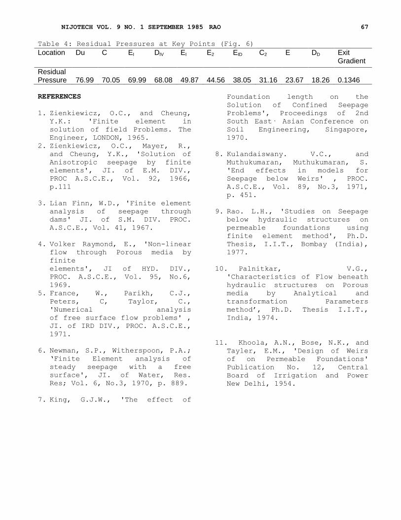
Finally the residual pressures
obtained at the key points for the
profile whom in Fig. 6 are given
below to show how intricate
construction details also can be
taken into account for analysis of
practical profiles by the finite
element method.
7. COMPUTER PROGRAM
The finite element method has
come into usage due to the advent of
high-speed digital computers for the
last two decades and it is very
obvious that the finite element
procedure will be of no use if
computers were not available to solve
the large number of simultaneous
equations obtained during the
process. The program is coded in
fort-ran language and has been used
with CDC-3600 computer which may be
easily understood with some knowledge
of Fortran-IV. More details of the
program listing can be found
elsewhere [9].
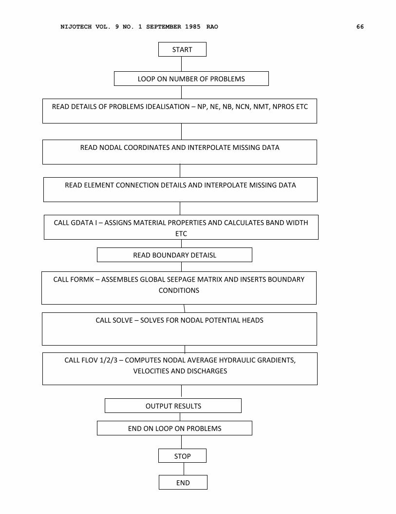
The program as shown in the flow
chart in Fig. 7 consists of series or
modules called subroutines. Data
input, element seepage matrix,
equation solving procedures are some
typical subroutines. The main program
is very simple whose only function is
calling the various subroutines in a
suitable order. The program can
consider different structural
configurations, boundary details, and
various non-homogeneous and
anisotropic conditions of the
materials. The program is oriented
for practical profiles consisting
horizontal, vertical and inclined
floors, and is capable of generating
finite element mesh (i.e. nodal
coordinates and elemental connection)
from the data of initial and final
values, which is done in the
subroutine G-DATA 1. The existing
finite element programs for
structural design have been consulted
in writing this program.
NIJOTECH VOL. 9 NO. 1 SEPTEMBER 1985 RAO 66
START
LOOP ON NUMBER OF PROBLEMS
READ DETAILS OF PROBLEMS IDEALISATION – NP, NE, NB, NCN, NMT, NPROS ETC
READ NODAL COORDINATES AND INTERPOLATE MISSING DATA
READ ELEMENT CONNECTION DETAILS AND INTERPOLATE MISSING DATA
CALL GDATA I – ASSIGNS MATERIAL PROPERTIES AND CALCULATES BAND WIDTH
ETC
READ BOUNDARY DETAISL
CALL FORMK – ASSEMBLES GLOBAL SEEPAGE MATRIX AND INSERTS BOUNDARY
CONDITIONS
CALL SOLVE – SOLVES FOR NODAL POTENTIAL HEADS
CALL FLOV 1/2/3 – COMPUTES NODAL AVERAGE HYDRAULIC GRADIENTS,
VELOCITIES AND DISCHARGES
END ON LOOP ON PROBLEMS
OUTPUT RESULTS
STOP
END
NIJOTECH VOL. 9 NO. 1 SEPTEMBER 1985 RAO 67
Table 4: Residual Pressures at Key Points (Fig. 6)
Location Du C EI DIV EI E2 EID C2 E DD Exit Gradient
Residual Pressure
76.99
70.05
69.99
68.08
49.87
44.56
38.05
31.16
23.67
18.26
0.1346
REFERENCES
1. Zienkiewicz, O.C., and Cheung,
Y.K.: 'Finite element in
solution of field Problems. The
Engineer, LONDON, 1965.
2. Zienkiewicz, O.C., Mayer, R.,
and Cheung, Y.K., 'Solution of
Anisotropic seepage by finite
elements', JI. of E.M. DIV.,
PROC A.S.C.E., Vol. 92, 1966,
p.111
3. Lian Finn, W.D., 'Finite element analysis of seepage through
dams' JI. of S.M. DIV. PROC.
A.S.C.E., Vol. 41, 1967.
4. Volker Raymond, E., 'Non-linear
flow through Porous media by
finite
elements', JI of HYD. DIV.,
PROC. A.S.C.E., Vol. 95, No.6,
1969.
5. France, W., Parikh, C.J.,
Peters, C, Taylor, C.,
'Numerical analysis
of free surface flow problems' ,
JI. of IRD DIV., PROC. A.S.C.E.,
1971.
6. Newman, S.P., Witherspoon, P.A.; ‘Finite Element analysis of
steady seepage with a free
surface', JI. of Water, Res.
Res; Vol. 6, No.3, 1970, p. 889.
7. King, G.J.W., 'The effect of
Foundation length on the
Solution of Confined Seepage
Problems', Proceedings of 2nd
South East· Asian Conference on
Soil Engineering, Singapore,
1970.
8. Kulandaiswany. V.C., and
Muthukumaran, Muthukumaran, S.
'End effects in models for
Seepage below Weirs' , PROC.
A.S.C.E., Vol. 89, No.3, 1971,
p. 451.
9. Rao. L.H., 'Studies on Seepage
below hydraulic structures on
permeable foundations using
finite element method', Ph.D.
Thesis, I.I.T., Bombay (India),
1977.
10. Palnitkar, V.G.,
'Characteristics of Flow beneath
hydraulic structures on Porous
media by Analytical and
transformation Parameters
method’, Ph.D. Thesis I.I.T.,
India, 1974.
11. Khoola, A.N., Bose, N.K., and
Tayler, E.M., 'Design of Weirs
of on Permeable Foundations'
Publication No. 12, Central
Board of Irrigation and Power
New Delhi, 1954.