
Solution Guide-CAP3
30
1 CHAPTER 3 PRACTICE SET Questions Q3-1. The answer is no. Host-to-host and process-to-process communication are needed because each computer in the Internet is designed to do multiple tasks: to run multiple application-layer programs. Q3-2. Although this can be done for client processes, it is very inefficient, if not impossible, for the server processes. When a server process starts running on the server, its number should be advertised by the server to all possible clients that need to contact that process. Q3-3. Although any port number can be used for the client and server and they can be the same in this private communication, it is recommended to follow the division specified by ICANN: a. The client port number should be chosen from the dynamic range, 49,152 to 65,535. b. The server port number also should be chosen from the dynamic range, 49,152 to 65,535. c. It is advisable to choose different port numbers for the server and the client to be able to better debug the programs. Q3-4. The organization needs to select a port number from the registered range, 1024 to 49,151, and register that port number with ICANN. If the port number is already in use, ICANN informs the organization to choose another port number in this range. Q3-5. We check each protocol one by one: a. The protocol can be Stop-and-Wait with the receive window size of 1 and the send window size of 1. b. The protocol can also be Go-Back-N with the receive window size of 1 and the send window size of n packets. c. The protocol cannot be Selective-Repeat because the size of both windows should be the same (1), which means the protocol is Stop-and-Wait, not Selective-Repeat. Q3-6. We check each protocol one by one:
description
Solution guide, Cap 3
Transcript of Solution Guide-CAP3
C H A P T E R 3
PRACTICE SET QuestionsQ3-1. The answer is no. Host-to-host and process-to-process communication areneeded because each computer in the Internet is designed to do multiple tasks:to run multiple application-layer programs.
Q3-2. Although this can be done for client processes, it is very inefficient, if notimpossible, for the server processes. When a server process starts running onthe server, its number should be advertised by the server to all possible clientsthat need to contact that process.
Q3-3. Although any port number can be used for the client and server and they canbe the same in this private communication, it is recommended to follow thedivision specified by ICANN:
a. The client port number should be chosen from the dynamic range, 49,152to 65,535.
b. The server port number also should be chosen from the dynamic range,49,152 to 65,535.
c. It is advisable to choose different port numbers for the server and the clientto be able to better debug the programs.
Q3-4. The organization needs to select a port number from the registered range,1024 to 49,151, and register that port number with ICANN. If the port numberis already in use, ICANN informs the organization to choose another portnumber in this range.
Q3-5. We check each protocol one by one:
a. The protocol can be Stop-and-Wait with the receive window size of 1 andthe send window size of 1.
b. The protocol can also be Go-Back-N with the receive window size of 1 andthe send window size of n packets.
c. The protocol cannot be Selective-Repeat because the size of both windowsshould be the same (1), which means the protocol is Stop-and-Wait, notSelective-Repeat.
Q3-6. We check each protocol one by one:
1
2
a. The protocol cannot be the Stop-and-Wait because the size of the send win-dow should be 1.
b. The protocol can be the Go-Back-N with the send window size of 20 andthe receive window size of 1 packet.
c. The protocol can be Selective-Repeat with the send window size of 20 andthe receive window size of 10.
Q3-7. We describe the advantage and disadvantage of each first:
a. The advantage of using the Go-Back-N protocol is that we can have alarger send window size. We can send more packets before waiting for theiracknowledgment. The disadvantage of using this protocol is that thereceive window size is only 1. The receiver cannot accept and store the out-of-order received packets; they will be discarded. Discarding of the out-of-order packets means resending these packets by the sender, resulting incongestion of the network and reducing the capacity of the pipe. So theadvantage seen by a larger send window may disappear by filling the net-work with resent packets.
b. The advantage of using the Selective-Repeat protocol is that the receivewindow can be much larger than 1. This allows the receive window to storethe out-of-order packets and avoids resending them to congest the network.On the other, the send window size of this protocol is half of the Go-Back-N, which means that we can send fewer packets before waiting for theacknowledgment.
c. If the bandwidth-delay product of the network is large, the reliability isgood, and the delay is low, we should choose the Go-Back-N protocol touse more of the network capacity. On the other hand, if the bandwidth-delay product is small, or the network is not very reliable, or the networkcreates long delays, we need to use Selective-Repeat.
Q3-8. Sequence numbers use modulo 2m arithmetic. This means that if a packet hasthe sequence number x, 2m packets need to be passed to see the same sequencenumber if each packet uses only one sequence number (not in TCP, where thesequence number defines the number of the first byte in the packet).
Q3-9. The networks need to be carefully designed to make the time between the twowraparounds as long as possible. For example, in a protocol that uses thesequence number field of size 3 (m 3), every 2m 8 packets have the samesequence number. If the previous packet with sequence number x (or its acci-dentally created duplicate) is still wandering in the network arrives at the des-tination, the receiver may confuse this with the expected new packet, also withsequence number x.
Q3-10. The transport-layer packets are encapsulated in the datagram at the networklayer. Each IP packet may travel a different route and arrives at the destinationwith a different delay. If a packet encounters more delay than the next packet,it will be received out of order.
3
Q3-11. The transport-layer packets are encapsulated in the datagram at the networklayer. The router through which the datagrams need to pass to reach their des-tination may be congested and drop the packets.
Q3-12. If a transport layer protocol such as TCP uses a timer and resends some pack-ets that have not arrived at the destination on time, it may happen that both theoriginal and the resent packet arrive at the destination.
Q3-13. The rest of the packets (2m 2) are supposed to be in transit, filling the pipe.The size of the receive window is chosen to be 1 to accept only one packet, theone expected, and not out-of order packets. The receiver cannot be over-whelmed because it holds only one packet in its window. When the onlypacket in the window is consumed by the upper-layer protocol, the receivewindow slides to make it possible to receive the next packet in transit. If anypacket in transit arrives before the window slides, it is discarded.
Q3-14. There can be several packets still in transit. The size of the receive window ischosen to be the same as the size of the send window to accommodate out-of-order packets until a set of packets all in order arrives. The protocol does notwant to deliver the out-of-order packets to the application-layer protocol.
Q3-15. The protocol field of the datagram (see Figures 4.24 and 4.25 in Chapter 4)defines the transport-layer protocol that should receive the transport-layerpacket. If the value is 06, the protocol is TCP; if the value is 17, the protocol isUDP.
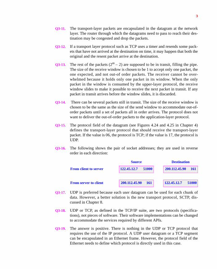
Q3-16. The following shows the pair of socket addresses; they are used in reverseorder in each direction:
Q3-17. UDP is preferred because each user datagram can be used for each chunk ofdata. However, a better solution is the new transport protocol, SCTP, dis-cussed in Chapter 8.
Q3-18. UDP or TCP, as defined in the TCP/IP suite, are two protocols (specifica-tions), not pieces of software. Their software implementations can be changedto accommodate the services required by different APIs.
Q3-19. The answer is positive. There is nothing in the UDP or TCP protocol thatrequires the use of the IP protocol. A UDP user datagram or a TCP segmentcan be encapsulated in an Ethernet frame. However, the protocol field of theEthernet needs to define which protocol is directly used in this case.
Source Destination
From client to server 122.45.12.7 51000 200.112.45.90 161
From server to client 200.112.45.90 161 122.45.12.7 51000
4
Q3-20. The answer is positive. UDP and TCP are independent protocols that do not tobe associated with the TCP/IP protocol suite. If another suite can create lowerlayers that provide services to UDP/TCP and upper layers that use the servicesof UDP/TCP, either of these protocols can be used as the end-to-end protocolin these suites.
Q3-21. There are two parties involved in a two-way communication. TCP allows eachparty to stop sending while the other party is still sending data. This means weneed at least two FIN segments (or data segments in which the FIN bit is set).Since each FIN segment should be acknowledged, we normally need four seg-ments for connection termination. Sometimes the second FIN segment can becombined with the ACK segment to reduce the number of segments to three.
Q3-22. The SYN segment cannot carry data. The SYN + ACK segment cannot carrydata either, but this segment is actually the SYN segment with an additionalACK bit. Although some people think that the FIN segment may not carrydata, it actually can. The client or the server can send the last bytes of data in asegment and set the FIN bit.
Q3-23. The way the sequence number is determined depends on whether the segmentis the first or not.
a. The sequence number of the first segment is the value of ISN, which is nor-mally selected according to the RFC 793.
b. The sequence number of any segment except the first is determined by thesequence number of the previous segment plus the number of sequencenumbers consumed by the previous segment. In other words, the sequencenumber of any segment is y x n, in which x is the sequence number ofthe previous segment and n is the count of sequence numbers consumed bythe previous segment. If the previous segment does not consume anysequence numbers, n 0.
Q3-24. We find the sequence number of the second segment in each case:
a. The sequence number of the second segment is 101 + 0 = 101.
b. The sequence number of the second segment is 101 + 10 = 111.
Q3-25.
a. A SYN segment consumes one sequence number.
b. An ACK segment does not consume any sequence numbers.
c. A SYN + ACK segment consumes one sequence number because it is aSYN segment.
d. A data segment consumes n sequence numbers, where n is the number ofbytes carried by the segment.
Q3-26. A segment that should be unambiguously acknowledged needs to consume asequence number; otherwise, the segment and the next one have the same
5
sequence number and it is not clear to which segment the acknowledgmentbelongs.
a. A SYN segment needs to be acknowledged unambiguously because itopens the connection.
b. A SYN + ACK is actually a combination of two segments; the first embed-ded segment, which is a SYN, needs to be acknowledged.
c. A FIN segment needs to be acknowledged unambiguously because it sig-nals closing of a connection.
d. An ACK segment that carries no data is never acknowledged (no ACK foran ACK). It, therefore, does not consume a sequence number.
Q3-27. We cannot say. The size of the window field makes the size of the window 216
bytes, but the sequence number is 232. The size of the window is definitelymuch smaller (actually 216 times smaller) than half of the range of thesequence numbers. The requirement of each protocol, Go-Back-N and Selec-tive-Repeat, is satisfied. However, as we mentioned in the text, TCP is closerto Selective-Repeat in other aspects.
Q3-28. The window size field of the TCP header is only 16 bits. A number with 16bits can define a decimal number between 0 and 65,535.
Q3-29.
a. The maximum size of the TCP header is 60 bytes (20 bytes of header and amaximum 40 bytes of options).
b. The minimum size of the TCP header is 20 bytes.
Q3-30. A SYN segment opens the connection in only one direction. For a communi-cation using TCP, two SYN segments are needed, one for each direction.
Q3-31. A FIN segment closes the connection in only one direction. The party thatissues a FIN segment cannot send data to the other party, but needs toacknowledge the data received from the other party. The other party can stillsend data and acknowledgments. To completely close the connection, two FINsegments are required, one in each direction. Of course, the FIN and ACKsegments can always be combined.
Q3-32. A segment carrying an RST flag can close the communication in both direc-tions immediately. The segment carrying an RST flag should not even beacknowledged.
Q3-33. For example, the SYN and the RST flags cannot be set in a segment. One ofthem requests the starting of a connection; the other requests that the connec-tion be aborted. Another example is the combination of SYN and FIN.
6
Q3-34. The server needs to immediately send a segment with the RST flag set to showthat the connection cannot be established. As we see in Chapter 4, if the net-work layer knows about the availability, it can also send an ICMP packet.
Q3-35. This is done through acknowledgment and retransmission. If a packet is lostor corrupted, it will be resent. As an analogy, assume the postal service isunreliable. When we send a letter to a friend, we can ask for confirmation witha postcard. If we do not receive the postcard, we can resend the copy of theletter until we finally get the confirmation.
Q3-36. A connection identifier in this case needs to include the identifier for two endpoints. In this case, a unique identifier for each end is defined by a socketaddress. The connection identifier should therefore be a pair of socketaddresses: the source socket address and the destination socket address.
Q3-37. A connection is distinguished by a pair of socket addresses, one for each end.Although the socket addresses at Bob’s site are the same in this case, thesocket addresses at Alice’s site are different. Each socket address at Alice’ssite has a different ephemeral port number.
Q3-38. In this case, Bob has made a passive open connection when he publiclyannounced his telephone number or privately gave her telephone number toAlice. Alice makes an active open when she dials Bob’s telephone number.
Q3-39. The sender window in TCP is originally the same size as the receiver window,but as the congestion builds up in the network, it can become smaller than thereceiver window. It can never become larger than the receiver window. Thesize of the sender window is the smaller of the window size either dictated bythe congestion or determined by the receiver.
Q3-40. A TCP segment or a combination of two or more segments can perform one ofthe following tasks:
a. Establishing a connection
b. Terminating a connection
c. Transferring data
d. Acknowledging the receipt of a segment
e. Advertising the window size (rwnd)
Q3-41. The answer depends on whether the segment is carrying data or not.
a. If the segment carries data, the sequence number defines the number of thefirst bytes in the segment.
b. If the segment carries no data (pure control segment), the sequence numberidentifies the segment itself.
Q3-42. The acknowledgment identifies the sequence number of the next segment thatis expected to arrive.
7
Q3-43. The use of checksum in UDP is optional. If the sender does not use the check-sum, it fills the checksum field with sixteen 0s. The use of the checksum inTCP, on the other hand, is mandatory. The sender should calculate the check-sum; otherwise, the checksum calculation at the receiver fails and the segmentis dropped.
Q3-44. The TCP server has received a segment whose sequence number is higherthan expected. The TCP server should store the out-of-order segment and sendan ACK with acknowledgment number 2001 to lead to the generation of aduplicate acknowledgment and possibly the fast retransmission of the missingsegment (Rule 4 in ACK generation).
Q3-45. The received segment is a duplicate. The TCP client needs to discard the seg-ment and immediately send an ACK with acknowledgment number 2001.This reaction helps the server to update itself if the previous ACK withacknowledgment number 2001 is somehow lost (Rule 6 in ACK generation).
Q3-46. The server needs to store the bytes in the buffer and sends an ACK withsequence number 2401. This reaction helps the client to purge the correspond-ing segment from its queue (Rule 5 in ACK generation).
Q3-47. The server needs to store the new bytes and immediately send an ACK withacknowledgment number 2901. This reaction prevents the retransmission ofthe previous segment by the client (Rule 3 in ACK generation).
Q3-48. The client needs to store the new bytes, but delay the acknowledgment untilreceiving the next segment or wait a period of 500 ms. This reduces the num-ber of ACKs in the network. (Rule 2 in ACK generation).
Q3-49. The server needs to store the new bytes, but send a segment with sequencenumber 4001 and acknowledgment number 8001 (piggybacking). This savesbandwidth because the data needs to go in the other direction, and it is betterto acknowledge the received bytes in the same packet (Rule 1 in ACK genera-tion).
Q3-50. Figures 3.59 and 3.60 define the FSMs for unidirectional communication. Thefirst rule of ACK generation is for bidirectional communication. It is the inter-action between the sender and receiver TCP at each end. The rule should beimplemented in the software.
Q3-51. The six rules we mentioned for ACK generation are related to flow and errorcontrol and are applicable during the data transmission phase, not during theconnection establishment phase. In this case, a SYN needs to be acknowl-edged by a (SYN + ACK) segment if the server accepts the connection or byan RST segment otherwise.
Q3-52. The six rules we mentioned for ACK generation are related to flow and errorcontrol and are applicable during the data transmission phase, not the connec-tion establishment phase. In this case, if the client accepts the connection, it
8
needs to send an ACK segment immediately or a data segment that acknowl-edges the SYN + ACK segment. Otherwise, it needs to send an RST segmentand abort the connection.
Q3-53. The six rules we mentioned for ACK generation are related to flow and errorcontrol and are applicable during the data transmission phase, not the connec-tion termination phase. In this case, the FIN segment should be acknowledgedimmediately if there is no data to send or acknowledged in the next data seg-ment.
Problems P3-1. The domain of IP addresses is universal. A device directly connected to the
Internet needs a unique IP address (see exceptions in Chapter 4). The domainof port numbers is local; they can be repeated. Two computers running theHTTP server process use the same well-known port number (80); two com-puters running the HTTP client process can use the same ephemeral port num-ber.
P3-2. Since port numbers have local jurisdiction and can be repeated, the divisiondistinguishes between client processes and server processes to avoid confu-sion when a host runs client and server processes at the same time. For exam-ple, assume host A is running a client process with the port number x, whichhas sent out a request and is waiting for a response from the correspondingserver. Host B sends a request to a server process with the port number x,which is received by host A. Host A erroneously passes the request to the cli-ent process with port number x, assuming that this is the response that the cli-ent process is waiting for. If client and server were using different portnumbers, x and y for example, the request received by host A would bedropped because no server with port number y was running. ICANN has alsodivided the server port numbers into two groups. The well-known port num-bers are recognized through the whole Internet society; the registered portnumbers are those that do not have a universal jurisdiction yet.
P3-3. The sequence number of any packet can be found using the following relation:
seqNo = (starting segNo + packet number 1) mod 2m
in which m is the number of bits used to define the sequence number. Thesequence number in this case is
P3-4. The wraparound depends on the value of m.
a. In the Stop-and-Wait protocol, m 1, every 2m = 2 packets have the samesequence number.
b. In the Go-Back-N protocol with m 8, every 2m = 256 packets have thesame sequence number.
seqNo (0 100 1) mod 25 99 mod 32 3
9
c. In the Selective-Repeat protocol with m 8, every 2m = 256 packets havethe same sequence number.
P3-5.
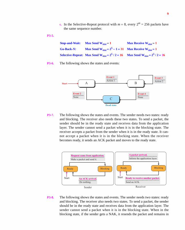
P3-6. The following shows the states and events:
P3-7. The following shows the states and events. The sender needs two states: readyand blocking. The receiver also needs these two states. To send a packet, thesender should be in the ready state and receives data from the applicationlayer. The sender cannot send a packet when it is in the blocking state. Thereceiver accepts a packet from the sender when it is in the ready state. It can-not accept a packet when it is in the blocking state. When the receiverbecomes ready, it sends an ACK packet and moves to the ready state.
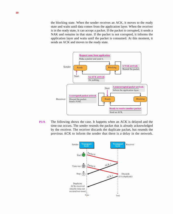
P3-8. The following shows the states and events. The sender needs two states: readyand blocking. The receiver also needs two states. To send a packet, the sendershould be in the ready state and receives data from the application layer. Thesender cannot send a packet when it is in the blocking state. When in theblocking state, if the sender gets a NAK, it resends the packet and remains in
Stop-and-Wait: Max Send Wsize 1 Max Receive Wsize 1
Go-Back-N: Max Send Wsize 25 1 31 Max Receive Wsize 1
Selective-Repeat: Max Send Wsize 25 / 2 16 Max Send Wsize 25 / 2 16
Action 1Event 1
None Event 2
None Event 4
Action 2 Event 3
Dead state
Start BA
C
Sender Receiver
Start
Make a packet and send it.
Ready
Request came from application.
An ACK arrived. Do nothing.
Blocking
Start
Ready
A packet arrived.
Ready to receive another packet. Send an ACK.
Inform the application layer.
Blocking
10
the blocking state. When the sender receives an ACK, it moves to the readystate and waits until data comes from the application layer. When the receiveris in the ready state, it can accept a packet. If the packet is corrupted, it sends aNAK and remains in that state. If the packet is not corrupted, it informs theapplication layer and waits until the packet is consumed. At this moment, itsends an ACK and moves to the ready state.
P3-9. The following shows the case. It happens when an ACK is delayed and thetime-out occurs. The sender resends the packet that is already acknowledgedby the receiver. The receiver discards the duplicate packet, but resends theprevious ACK to inform the sender that there is a delay in the network.
Sender
Receiver
Start
Make a packet and send it.
Ready
Request came from application.
An ACK arrived. Do nothing.
A NAK arrived. Resend the packet.
A corrupted packet arrived. Discard the packet.Send a NAK.
Blocking
Start
Ready
A noncorrupted packet arrived.
Ready to receive another packet. Send an ACK.
Inform the application layer.
Blocking
DuplicateACKs received
(maybe time-out occured too soon)
Stop
Time-out
Time Time
Packet 0
Packet 0 ACK 1
ACK 1Discards
(it is duplicate)
Start
Sender ReceiverTransportlayer
Transportlayer
11
Receiving a duplicate ACK may alert the sender to increase the time-out toprevent resending the packets prematurely. Note that if the receiver ignoresthe duplicate packet and does not send the second ACK, the sender believesthat the first packet is lost and the first ACK is actually acknowledging thepacket that is resent. Duplicate ACKs give the clue about what is happening.
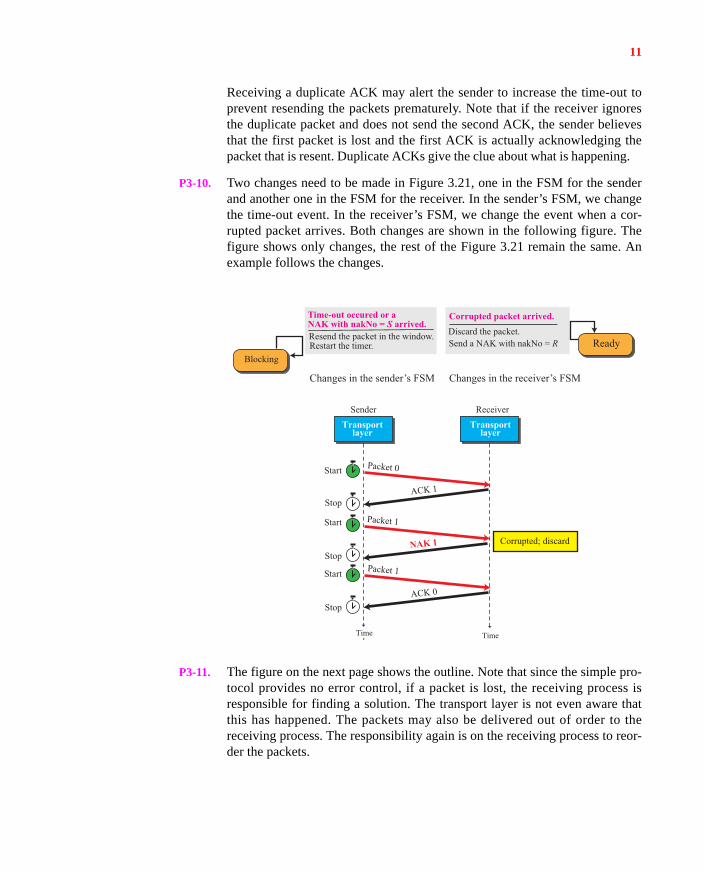
P3-10. Two changes need to be made in Figure 3.21, one in the FSM for the senderand another one in the FSM for the receiver. In the sender’s FSM, we changethe time-out event. In the receiver’s FSM, we change the event when a cor-rupted packet arrives. Both changes are shown in the following figure. Thefigure shows only changes, the rest of the Figure 3.21 remain the same. Anexample follows the changes.
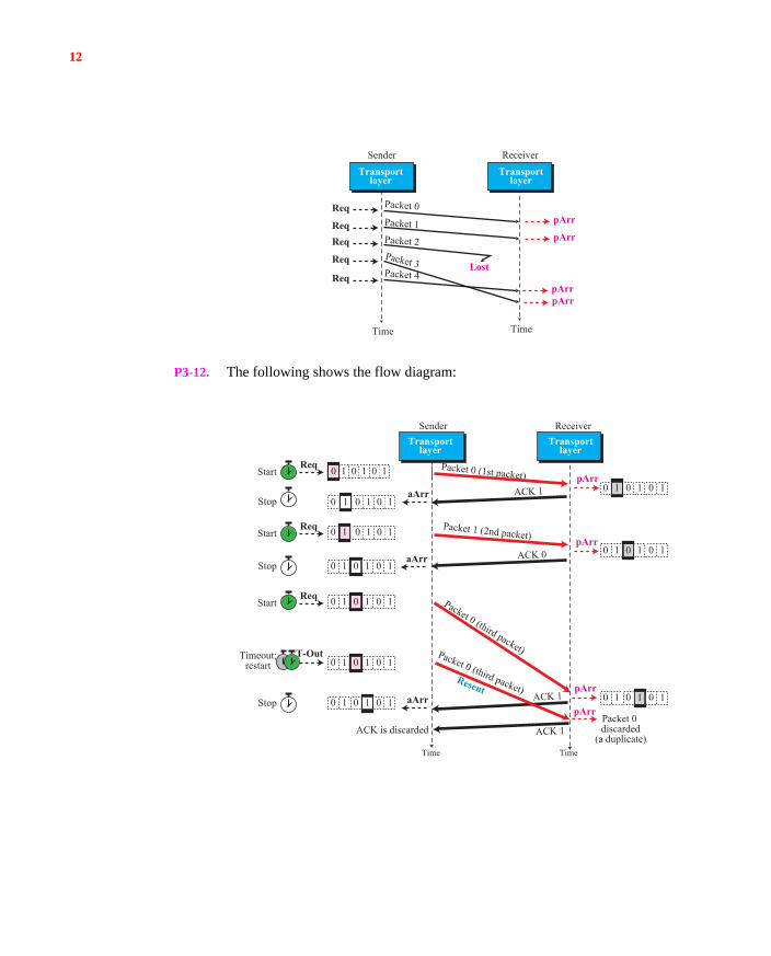
P3-11. The figure on the next page shows the outline. Note that since the simple pro-tocol provides no error control, if a packet is lost, the receiving process isresponsible for finding a solution. The transport layer is not even aware thatthis has happened. The packets may also be delivered out of order to thereceiving process. The responsibility again is on the receiving process to reor-der the packets.
Changes in the sender’s FSM
Time-out occured or a NAK with nakNo = S arrived. Resend the packet in the window. Restart the timer.
Blocking
Changes in the receiver’s FSM
Discard the packet. Send a NAK with nakNo = R
Corrupted packet arrived.
Ready
Stop
Time Time
Packet 0
ACK 1
Corrupted; discard
Start
Stop
Start
Stop
Start
Sender ReceiverTransport
layerTransport
layer
Packet 1
NAK 1
Packet 1
ACK 0
12
P3-12. The following shows the flow diagram:
Time Time
Sender ReceiverTransport
layerTransport
layer
Packet 0Packet 1Packet 2Packet 3Packet 4
pArrReq
ReqReq
Req
Req
pArr
Lost
pArrpArr
Stop
Timeout;restart
Packet 0 discarded
(a duplicate)ACK is discarded
Time Time
Packet 0 (1st packet)ACK 1
ACK 1
ACK 1
ACK 0
Start
Packet 1 (2nd packet)
Packet 0 (third packet)Packet 0 (third packet)Resent
Sender ReceiverTransport
layerTransport
layer
pArraArr
Req
Stop
Stop
StartReq
StartReq
T-Out
aArr
aArr
pArr
pArr
pArr
0 1 00 1110 00 11
1 00 0 11010 0 11
10 00 11
00 1110
10 0 110
10 0 110
0 110 0 1 1010 0 1
13
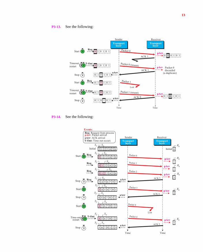
P3-13. See the following:
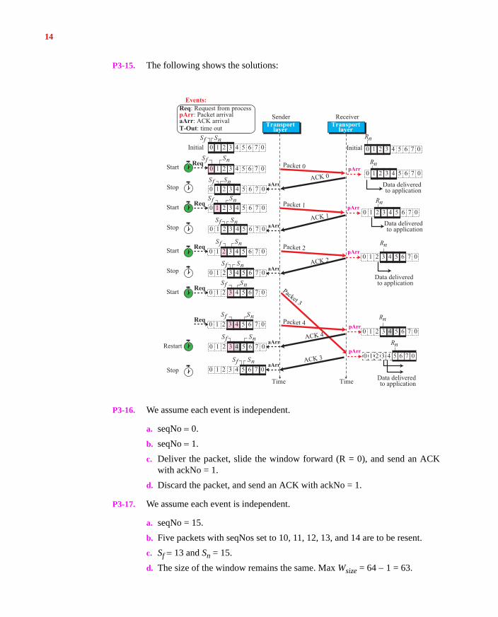
P3-14. See the following:
Lost
Start
Stop
Timeout;restart
Timeout;restart
Packet 0 discarded
(a duplicate)
Time Time
Packet 0
Packet 1 (resent)
Packet 1
ACK 1
Start
Stop
Packet 0 (resent)
ACK 1
ACK 0
Sender ReceiverTransport
layerTransport
layer
pArrReq
Req
T-Out
T-Out
aArr
aArr
pArr
pArr
00 111 0
00 111 0
00 111 0
00 1110
00 1110
000 111
1 0 00 110 00 11 1
Start
Initial Initial
Time-out:restart
Stop
1
2
3
4
Sf Sn0 1 2 3 4 5 6
Sf Sn0 1 2 3 4 5 6
Sf Sn0 13 4 5 6 7
Sf Sn0 1 24 5 6 7
pArrReq
Time
Lost
Time
Packet 0
ACK 3
Rn
0Rn
Rn
Rn
Rn
Rn
Start
Stop
Start
Stop
Packet 1
Packet 2
Packet 3
Packet 4
Packet 4
ACK 4
ACK 5
Sf Sn0 1 2 3 4 5 6
Req
Sf Sn0 1 2 3 4 5 6
Req
Sf Sn3 4 5 6 7
Req
aArr
aArr
aArr
Sf Sn0 1 24 5 6 7
Sf Sn0 1 24 5 6 7
Sf Sn0 1 2 35 6 7
pArr
pArr
pArr
5pArr
Sender ReceiverTransport
layerTransport
layer
0 1
T-Out
Req: Request from processpArr: Packet arrival
Events:
aArr: ACK arrivalT-Out: Time out occurs
14
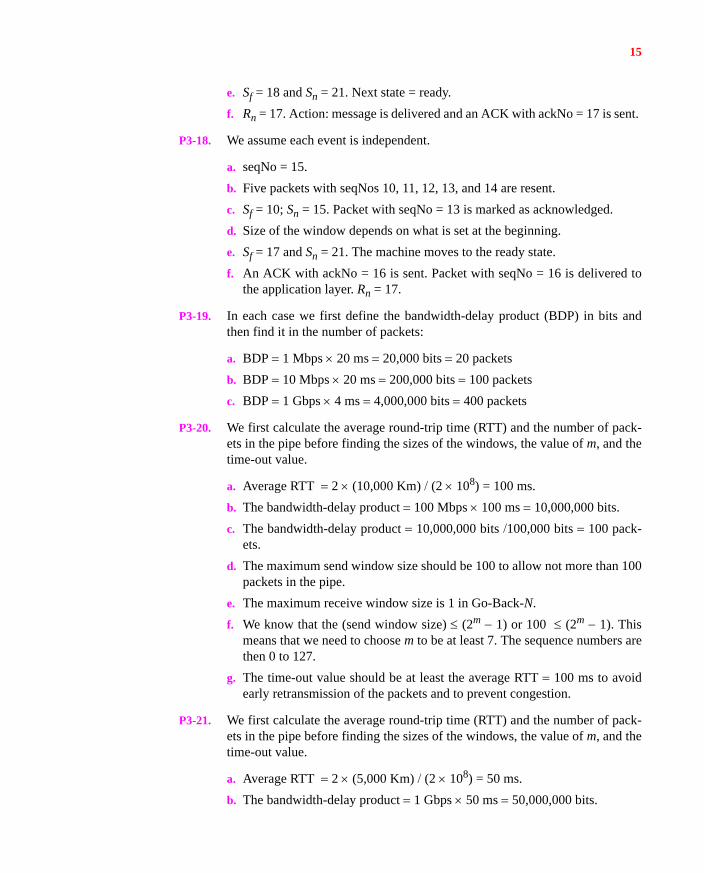
P3-15. The following shows the solutions:
P3-16. We assume each event is independent.
a. seqNo 0.
b. seqNo 1.
c. Deliver the packet, slide the window forward (R = 0), and send an ACKwith ackNo = 1.
d. Discard the packet, and send an ACK with ackNo = 1.
P3-17. We assume each event is independent.
a. seqNo = 15.
b. Five packets with seqNos set to 10, 11, 12, 13, and 14 are to be resent.
c. Sf 13 and Sn = 15.
d. The size of the window remains the same. Max Wsize = 64 1 = 63.
Rn
Rn
Initial
TimeTime
Sf Sn
Sf Sn
Initial
Data deliveredto application
Rn
Sf Sn
Sender ReceiverTransport
layerTransport
layerT-Out: time out
Req: Request from processpArr: Packet arrival
Events:
aArr: ACK arrival
Start
StopACK 0
ACK 1
ACK 4
Packet 0
Packet 1
Packet 3
pArrReq
Sf Sn
Sf Sn
Start
Stop
Req
Sf Sn
Sf Sn
Start
Stop
Stop
Req
aArr
aArr
aArr
Sf Sn
Sf Sn
Sf Sn
Start
Restart
Req
Req
aArr
Sf Sn aArr
pArr
pArr
pArr
ACK 2
Packet 2
ACK 3
Packet 4
Data deliveredto application
Rn
Data deliveredto application
Data deliveredto application
Rn
0pArr
Rn
1 2 3 4 5 6 70
04 5 6 70 321 04 5 6 70 321
0 05 6 73 421
10 06 73 4 52
1 20 073 4 5 6
41 20 073 5 6
0 04 5 6 7321
0 4 05 6 7321
0 4 05 6 7321
10 4 5 06 732
210 4 5 06 73
1 20 4 5 6 073
31 20 4 5 6 07
3 41 20 5 6 07
431 20 5 6 07
1 2 3 40 5 6 7 0
15
e. Sf = 18 and Sn = 21. Next state = ready.
f. Rn = 17. Action: message is delivered and an ACK with ackNo = 17 is sent.
P3-18. We assume each event is independent.
a. seqNo = 15.
b. Five packets with seqNos 10, 11, 12, 13, and 14 are resent.
c. Sf = 10; Sn = 15. Packet with seqNo = 13 is marked as acknowledged.
d. Size of the window depends on what is set at the beginning.
e. Sf = 17 and Sn = 21. The machine moves to the ready state.
f. An ACK with ackNo = 16 is sent. Packet with seqNo = 16 is delivered tothe application layer. Rn = 17.
P3-19. In each case we first define the bandwidth-delay product (BDP) in bits andthen find it in the number of packets:
a. BDP 1 Mbps 20 ms 20,000 bits 20 packets
b. BDP 10 Mbps 20 ms 200,000 bits 100 packets
c. BDP 1 Gbps 4 ms 4,000,000 bits 400 packets
P3-20. We first calculate the average round-trip time (RTT) and the number of pack-ets in the pipe before finding the sizes of the windows, the value of m, and thetime-out value.
a. Average RTT 2 (10,000 Km) (2 108) = 100 ms.
b. The bandwidth-delay product 100 Mbps 100 ms 10,000,000 bits.
c. The bandwidth-delay product 10,000,000 bits 100,000 bits 100 pack-ets.
d. The maximum send window size should be 100 to allow not more than 100packets in the pipe.
e. The maximum receive window size is 1 in Go-Back-N.
f. We know that the (send window size) (2m 1) or 100 (2m 1). Thismeans that we need to choose m to be at least 7. The sequence numbers arethen 0 to 127.
g. The time-out value should be at least the average RTT 100 ms to avoidearly retransmission of the packets and to prevent congestion.
P3-21. We first calculate the average round-trip time (RTT) and the number of pack-ets in the pipe before finding the sizes of the windows, the value of m, and thetime-out value.
a. Average RTT 2 (5,000 Km) (2 108) = 50 ms.
b. The bandwidth-delay product 1 Gbps 50 ms 50,000,000 bits.
16
c. The bandwidth-delay product 50,000,000 bits 50,000 bits 1000 pack-ets.
d. The maximum send window size should be 1000 to allow not more than1000 packets in the pipe.
e. The maximum receive window size should also be 1000 packets.
f. We know that the (window size) (2m 1) or 1000 (2m 1). This meansthat we need to choose (m 1) to be at least 10 or m 11. The sequencenumbers are then 0 to 2047.
g. The timeout value should be at least the average RTT 50 ms to avoidearly retransmission of the packets and to prevent congestion.
P3-22.
a. In the Go-Back-N protocol, since the receiver does not accept any out- of-order data packets, acknowledgments are cumulative, which means that thereceiver does not have to acknowledge any single data packet received.Several packets can be acknowledged at a time, saving in the number ofACK packets. In this system, a single acknowledgment number defines thenext packet that the receiver expects to receive to allow the sender to purgethe whole range of packets whose sequence number is less than theacknowledgment number. For example, if the acknowledgment number isackNo 27, the sender can purge all of the outstanding packets whosesequence number is less than 27. The acknowledgment number clearlydefines the first slot in the sender window after sliding.
b. In the Selective-Repeat protocol, the receiver can accept out-of-order pack-ets and store them until the missing packets arrive. In this protocol, theacknowledgment number cannot be cumulative, because several packetsbefore the one received may not have been received yet. Nor can’t theacknowledgment define the next packet expected, because the next packetmay be a packet with sequence number before or after the one received.The acknowledgment number exactly defines the sequence number of thepacket received.
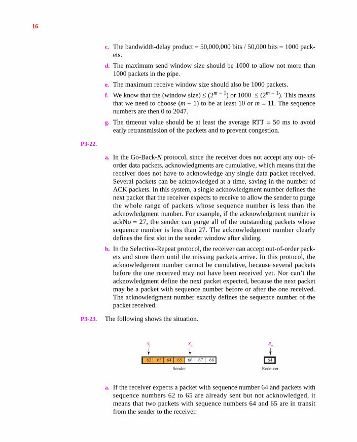
P3-23. The following shows the situation.
a. If the receiver expects a packet with sequence number 64 and packets withsequence numbers 62 to 65 are already sent but not acknowledged, itmeans that two packets with sequence numbers 64 and 65 are in transitfrom the sender to the receiver.
62 63 67 68
Sender Receiver
65 66
Sf Sn
64 64
Rn
17
b. If the sender expects the acknowledgment for packet 62, but the value of Rn 64, it means that the ACK packets with acknowledgment numbers 62 and63 are in transit from the receiver to the sender.
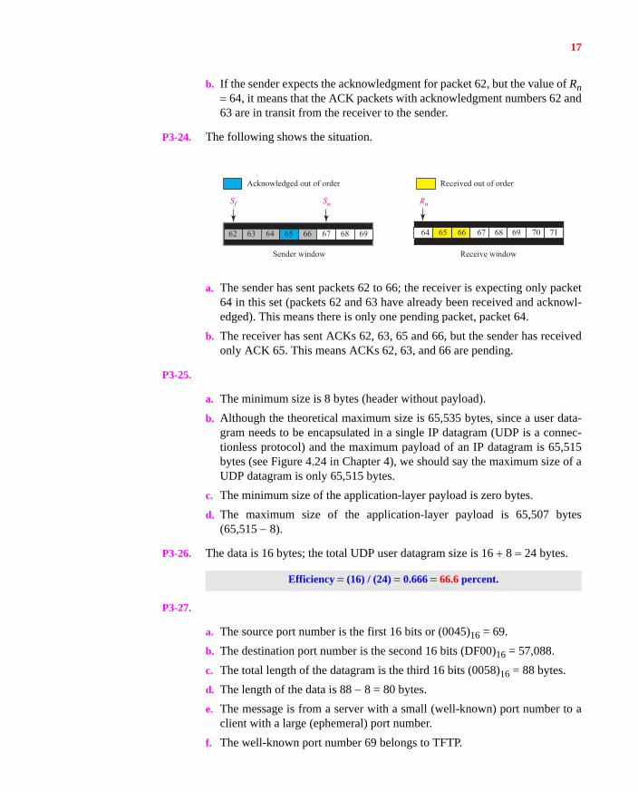
P3-24. The following shows the situation.
a. The sender has sent packets 62 to 66; the receiver is expecting only packet64 in this set (packets 62 and 63 have already been received and acknowl-edged). This means there is only one pending packet, packet 64.
b. The receiver has sent ACKs 62, 63, 65 and 66, but the sender has receivedonly ACK 65. This means ACKs 62, 63, and 66 are pending.
P3-25.
a. The minimum size is 8 bytes (header without payload).
b. Although the theoretical maximum size is 65,535 bytes, since a user data-gram needs to be encapsulated in a single IP datagram (UDP is a connec-tionless protocol) and the maximum payload of an IP datagram is 65,515bytes (see Figure 4.24 in Chapter 4), we should say the maximum size of aUDP datagram is only 65,515 bytes.
c. The minimum size of the application-layer payload is zero bytes.
d. The maximum size of the application-layer payload is 65,507 bytes(65,515 8).
P3-26. The data is 16 bytes; the total UDP user datagram size is 16 8 24 bytes.
P3-27.
a. The source port number is the first 16 bits or (0045)16 = 69.
b. The destination port number is the second 16 bits (DF00)16 = 57,088.
c. The total length of the datagram is the third 16 bits (0058)16 = 88 bytes.
d. The length of the data is 88 8 = 80 bytes.
e. The message is from a server with a small (well-known) port number to aclient with a large (ephemeral) port number.
f. The well-known port number 69 belongs to TFTP.
Efficiency (16) / (24) 0.666 66.6 percent.
62 63 67 6865 66 69
Sf Sn
64 66 6764 65 68 69
Acknowledged out of order Received out of order
Sender window Receive window
71
Rn
70
18
g. The sender has not calculated the checksum for this packet because thevalue of the checksum is all zeros.
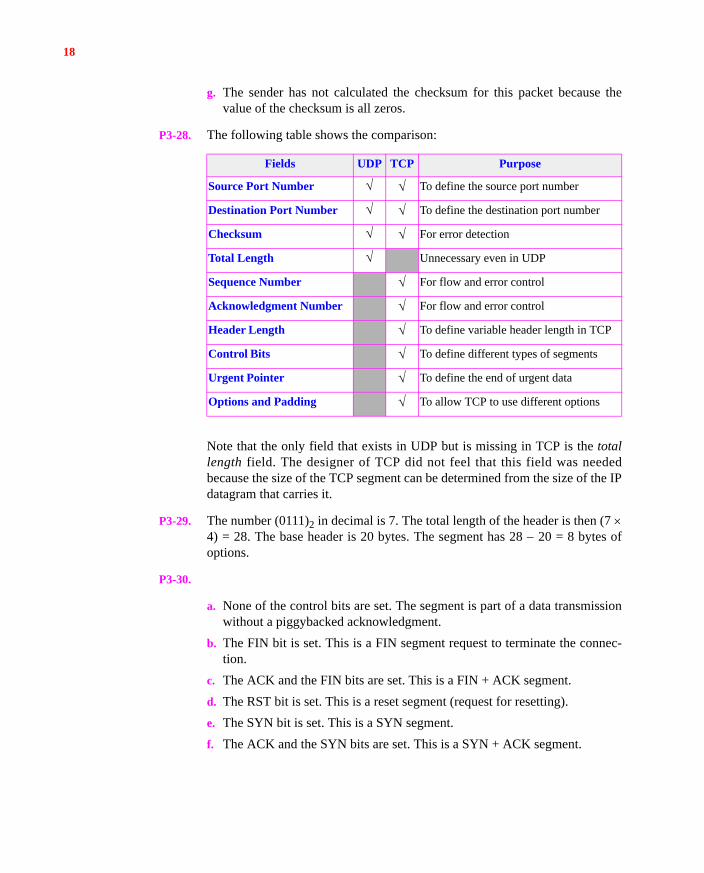
P3-28. The following table shows the comparison:
Note that the only field that exists in UDP but is missing in TCP is the totallength field. The designer of TCP did not feel that this field was neededbecause the size of the TCP segment can be determined from the size of the IPdatagram that carries it.
P3-29. The number (0111)2 in decimal is 7. The total length of the header is then (7 4) = 28. The base header is 20 bytes. The segment has 28 20 = 8 bytes ofoptions.
P3-30.
a. None of the control bits are set. The segment is part of a data transmissionwithout a piggybacked acknowledgment.
b. The FIN bit is set. This is a FIN segment request to terminate the connec-tion.
c. The ACK and the FIN bits are set. This is a FIN + ACK segment.
d. The RST bit is set. This is a reset segment (request for resetting).
e. The SYN bit is set. This is a SYN segment.
f. The ACK and the SYN bits are set. This is a SYN + ACK segment.
Fields UDP TCP Purpose
Source Port Number To define the source port number
Destination Port Number To define the destination port number
Checksum For error detection
Total Length Unnecessary even in UDP
Sequence Number For flow and error control
Acknowledgment Number For flow and error control
Header Length To define variable header length in TCP
Control Bits To define different types of segments
Urgent Pointer To define the end of urgent data
Options and Padding To allow TCP to use different options
19
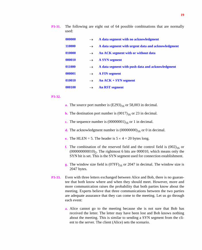
P3-31. The following are eight out of 64 possible combinations that are normallyused:
P3-32.
a. The source port number is (E293)16 or 58,003 in decimal.
b. The destination port number is (0017)16 or 23 in decimal.
c. The sequence number is (00000001)16 or 1 in decimal.
d. The acknowledgment number is (00000000)16 or 0 in decimal.
e. The HLEN = 5. The header is 5 4 = 20 bytes long.
f. The combination of the reserved field and the control field is (002)16 or(000000000010)2. The rightmost 6 bits are 000010, which means only theSYN bit is set. This is the SYN segment used for connection establishment.
g. The window size field is (07FF)16 or 2047 in decimal. The window size is2047 bytes.
P3-33. Even with three letters exchanged between Alice and Bob, there is no guaran-tee that both know where and when they should meet. However, more andmore communication raises the probability that both parties know about themeeting. Experts believe that three communications between the two partiesare adequate assurance that they can come to the meeting. Let us go througheach event:
a. Alice cannot go to the meeting because she is not sure that Bob hasreceived the letter. The letter may have been lost and Bob knows nothingabout the meeting. This is similar to sending a SYN segment from the cli-ent to the server. The client (Alice) sets the scenario.
000000 A data segment with no acknowledgment
110000 A data segment with urgent data and acknowledgment
010000 An ACK segment with or without data
000010 A SYN segment
011000 A data segment with push data and acknowledgment
000001 A FIN segment
010010 An ACK + SYN segment
000100 An RST segment
20
b. Bob cannot go to the meeting because he does know if Alice has receivedhis confirmation. This is similar to the SYN + ACK. The server (Bob) con-firms Alice’s request.
c. Alice cannot go to the meeting with total assurance that Bob will be therebecause she does not know if Bob has received her letter and knows thatshe knows that the meeting is confirmed. This is similar to the last ACK.The client (Alice) confirms that she has received the confirmation from theserver (Bob).
P3-34. Every second the counter is incremented by 64,000 2 = 128,000. Thesequence number field is 32 bits long and can hold only 2321. So it takes(2321)/(128,000) or 33,554 seconds (almost 9 hours and 19 minutes) to wraparound.
P3-35.
a. The sequence number in the SYN segment is 2171. The SYN segment con-sumes one sequence number; the next sequence number to be used is 2172.
b. The sequence number in the data segment is 2172 (which represents thesequence number of the first byte). The bytes in the packets are numbered2172 to 3171. Note that the client sends the data with the second packet (noseparate ACK segment).
c. The sequence number in the FIN segment is 3172. Note that the FIN seg-ment does consume a sequence number.
P3-36. The window size is min(3000, 5000) = 3000. Since 2000 bytes is already sent,only 3000 2000 = 1000 more bytes can be sent.
P3-37. The data section is only 16 bytes. The TCP header is 20 bytes. The efficiencyis
P3-38. The largest number in the sequence number field is 232 1. If we start at 7000,it takes [(232 1) 7000] / 1,000,000 = 4295 seconds or almost 72 minutes.
(16) (16 20) 0.444 44.4%
21
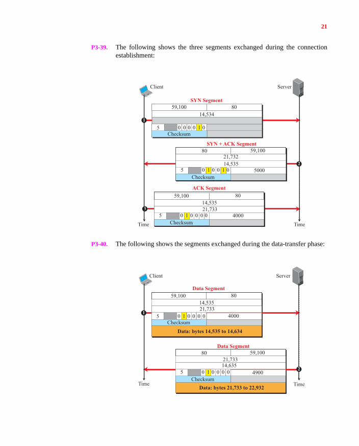
P3-39. The following shows the three segments exchanged during the connectionestablishment:
P3-40. The following shows the segments exchanged during the data-transfer phase:
Checksum
8059,10014,534
7855 0 0 0 0 1 00
SYN Segment
Time
Client Server
Time
SYN + ACK Segment
8059,10014534
7855 4000
Checksum0 1 0 0 0 0
21,73314,535
ACK Segment
5910021,732
7855 5000
Checksum0 1 0 0 1 0
14,535
80
3
1
2
59,100
Data Segment
Time
Server
Time
Client
Data Segment
1
2
Checksum
8059,10014,535
7855 0 1 0 0 0 00
21,733
Data: bytes 14,535 to 14,634
4000
21,733785
5Checksum
0 1 0 0 0 014,635
80 59,100
Data: bytes 21,733 to 22,932
4900
22
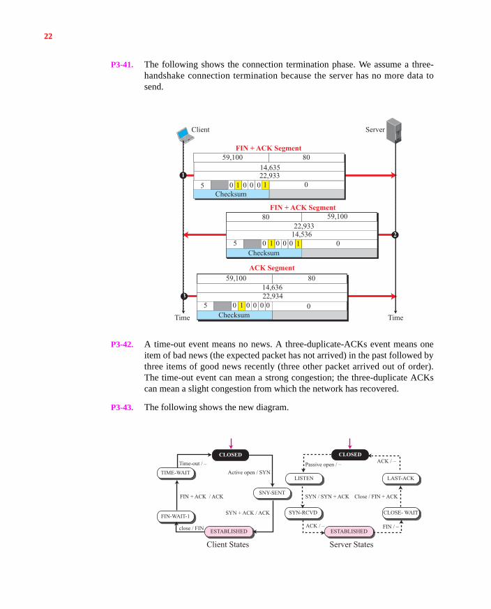
P3-41. The following shows the connection termination phase. We assume a three-handshake connection termination because the server has no more data tosend.
P3-42. A time-out event means no news. A three-duplicate-ACKs event means oneitem of bad news (the expected packet has not arrived) in the past followed bythree items of good news recently (three other packet arrived out of order).The time-out event can mean a strong congestion; the three-duplicate ACKscan mean a slight congestion from which the network has recovered.
P3-43. The following shows the new diagram.
Checksum
8059,10014,635785
5 0 0 01 100
FIN + ACK Segment
Time
Client Server
Time
FIN + ACK Segment
8059,10014534
7855
Checksum0 1 0 0 0 0
22,93414,636
ACK Segment
5910022,933785
5
0
0
0
Checksum0 1 0 0 0
14,536
80
3
1
2
59,100
22,933
1
FIN-WAIT-1FIN-WAIT-1
TIME-WAITTIME-WAIT
ESTABLISHEDESTABLISHED
SNY-SENTSNY-SENT
SYN-RCVDSYN-RCVD
ESTABLISHEDESTABLISHED
LAST-ACKLAST-ACK
CLOSE- WAITCLOSE- WAIT
ACK / – FIN / –
FIN + ACK / ACK Close / FIN + ACK
close / FIN
Active open / SYNPassive open / _Time-out / – ACK / –
SYN / SYN + ACK
SYN + ACK / ACK
Client States Server States
CLOSEDCLOSED
LISTENLISTEN
23
Note that the FIN-WAIT-2 state is not used in this case. Note also that thereare changes in the server side that are not shown in Figure 3.51 (in the text)because this is somewhat of an implementation issue. In this case, the serversends FIN + ACK before going to the LAST-ACK state.
P3-44. If Bob, the server, always uses a different ISN (Initial Sequence Number), Evecannot create such a connection easily. Let us go through the three hand-shakeevents:
a. Eve sends a SYN segment using Alice’s IP address as the source IPaddress.
b. Bob (the server) sends the SYN + ACK segment to Alice (not to Eve)because the destination address is Alice’s address.
c. Since Alice has not initiated this connection, the third segment (ACK seg-ment) will not be generated. If Bob has used a randomly generatedsequence number (ISN), Eve cannot send the ACK segment because theacknowledgment number should be 1 plus the ISN used by Bob unless Eveintercepts the SYN + ACK packet and finds the ISN used by Bob, which isanother issue. However, if Bob always uses the same ISN, then Eve cancreate the ACK message.
P3-45. Bob, the server, sends the response to Alice’s IP address; the destination IPaddress is the source IP address in the request message. Since Alice has notrequested this response, the response is dropped and lost. Eve can receive theresponse only if she can intercept the message.
P3-46. The probability of this mistake is very low. In TCP, an ISN (Initial SequenceNumber) for a connection always has a high probability of being unique.When Alice sends the new SYN, its sequence number is different from thesequence number of the wandering SYN. Assume the sequence number of theold SYN is x and the sequence number of the new SYN is y. The SYN + ACKsegment sent by Bob in response to the old SYN has the acknowledgmentnumber (x + 1); Alice is expecting the acknowledgment number of (y + 1) forthe new SYN. Alice immediately sends an RST (reset) segment and aborts theconnection. Alice then needs to start a new connection.
P3-47. The probability of this mistake is very low because the initial sequence num-ber (ISN) has a high probability of being unique. Assume Alice and Bob wereusing ISNs x and y, respectively in the previous connection, but z and t in thisconnection. The old ACK segment (third segment) has the acknowledgmentnumber (y + 1); the new ACK segment should have the acknowledgment (t +1). Bob’s server immediately recognizes the problem and sends an RST seg-ment to abort the connection. Alice then needs to start a new connection.
24
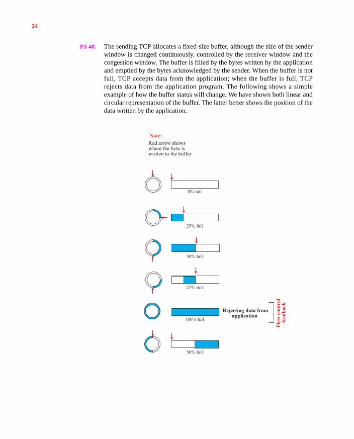
P3-48. The sending TCP allocates a fixed-size buffer, although the size of the senderwindow is changed continuously, controlled by the receiver window and thecongestion window. The buffer is filled by the bytes written by the applicationand emptied by the bytes acknowledged by the sender. When the buffer is notfull, TCP accepts data from the application; when the buffer is full, TCPrejects data from the application program. The following shows a simpleexample of how the buffer status will change. We have shown both linear andcircular representation of the buffer. The latter better shows the position of thedata written by the application.
0% full
Red arrow showswhere the byte iswritten to the buffer
25% full
50% full
Rejecting data fromapplication
Note:
50% full
25% full
100% full
Flow
con
trol
fe
edba
ck
25
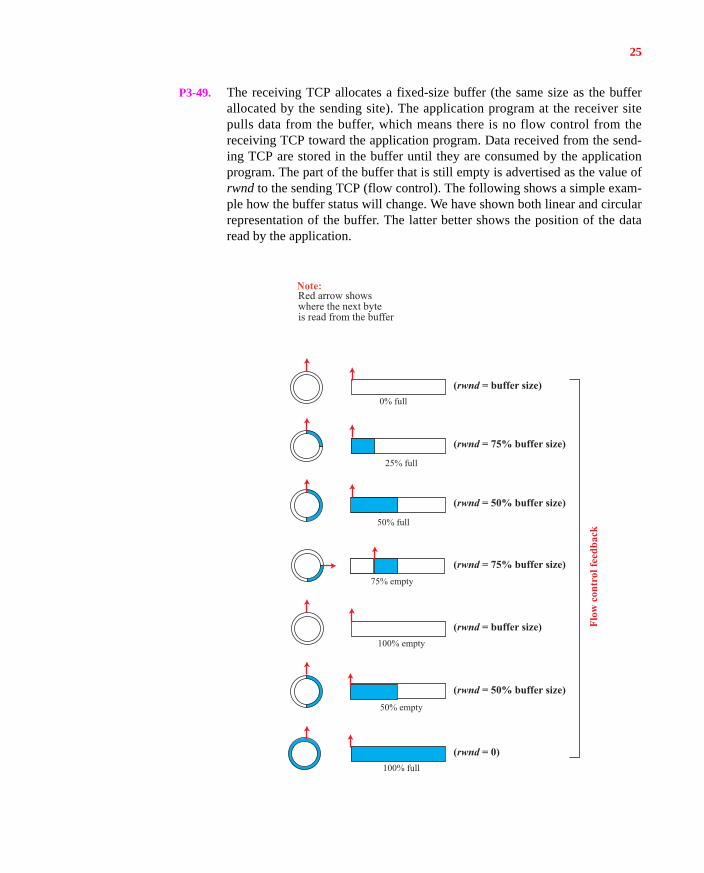
P3-49. The receiving TCP allocates a fixed-size buffer (the same size as the bufferallocated by the sending site). The application program at the receiver sitepulls data from the buffer, which means there is no flow control from thereceiving TCP toward the application program. Data received from the send-ing TCP are stored in the buffer until they are consumed by the applicationprogram. The part of the buffer that is still empty is advertised as the value ofrwnd to the sending TCP (flow control). The following shows a simple exam-ple how the buffer status will change. We have shown both linear and circularrepresentation of the buffer. The latter better shows the position of the dataread by the application.
0% full
Red arrow showswhere the next byte is read from the buffer
Flow
con
trol
feed
back
25% full
50% full
100% full
(rwnd = buffer size)
(rwnd = buffer size)
(rwnd = 75% buffer size)
(rwnd = 75% buffer size)
(rwnd = 50% buffer size)
(rwnd = 50% buffer size)
(rwnd = 0)
Note:
50% empty
75% empty
100% empty
26
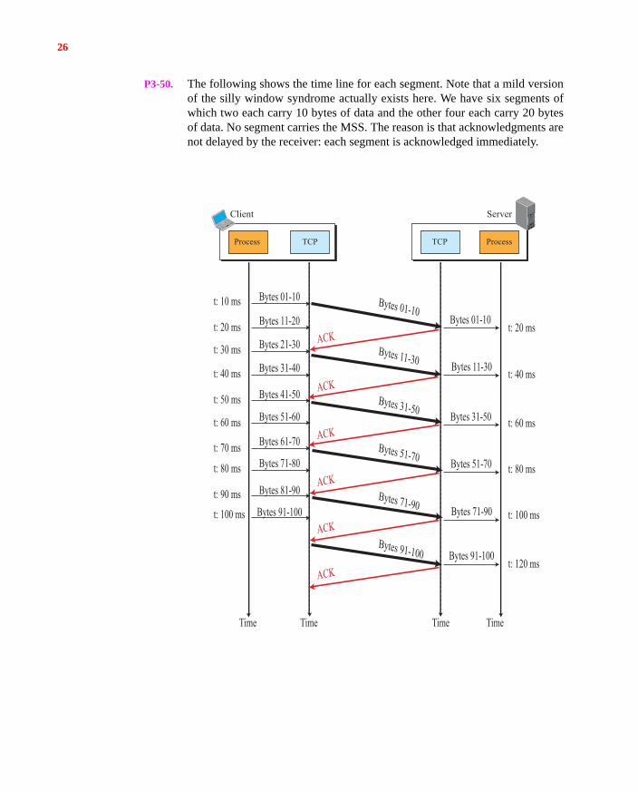
P3-50. The following shows the time line for each segment. Note that a mild versionof the silly window syndrome actually exists here. We have six segments ofwhich two each carry 10 bytes of data and the other four each carry 20 bytesof data. No segment carries the MSS. The reason is that acknowledgments arenot delayed by the receiver: each segment is acknowledged immediately.
Time
Client Server
Bytes 01-10t: 10 ms
t: 20 ms
t: 30 ms
t: 40 ms
t: 50 ms
t: 60 ms
t: 70 ms
t: 80 ms
t: 90 ms
t: 100 ms
t: 20 ms
t: 40 ms
t: 60 ms
t: 80 ms
t: 100 ms
t: 120 ms
Bytes 01-10Bytes 01-10
ACK
ACK
ACK
ACK
ACK
ACK
Bytes 11-20
Bytes 11-30Bytes 11-30
Bytes 31-50Bytes 31-50
Bytes 51-70Bytes 51-70
Bytes 71-90Bytes 71-90
Bytes 91-100Bytes 91-100
Bytes 21-30
Bytes 31-40
Bytes 41-50
Bytes 51-60
Bytes 61-70
Bytes 71-80
Bytes 81-90
Bytes 91-100
Time TimeTime
TCP TCPProcess Process
27
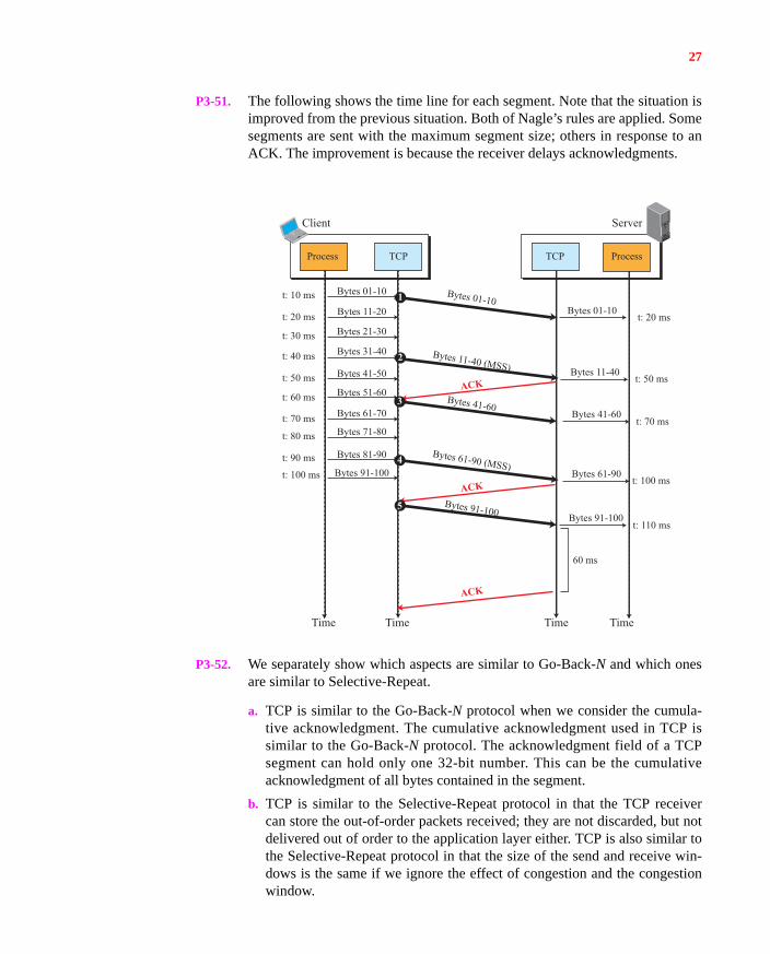
P3-51. The following shows the time line for each segment. Note that the situation isimproved from the previous situation. Both of Nagle’s rules are applied. Somesegments are sent with the maximum segment size; others in response to anACK. The improvement is because the receiver delays acknowledgments.
P3-52. We separately show which aspects are similar to Go-Back-N and which onesare similar to Selective-Repeat.
a. TCP is similar to the Go-Back-N protocol when we consider the cumula-tive acknowledgment. The cumulative acknowledgment used in TCP issimilar to the Go-Back-N protocol. The acknowledgment field of a TCPsegment can hold only one 32-bit number. This can be the cumulativeacknowledgment of all bytes contained in the segment.
b. TCP is similar to the Selective-Repeat protocol in that the TCP receivercan store the out-of-order packets received; they are not discarded, but notdelivered out of order to the application layer either. TCP is also similar tothe Selective-Repeat protocol in that the size of the send and receive win-dows is the same if we ignore the effect of congestion and the congestionwindow.
Time
Client Server
Bytes 01-10t: 10 ms
t: 20 ms
t: 30 ms
t: 40 ms
t: 50 ms
t: 60 ms
t: 70 ms
t: 80 ms
t: 90 ms
t: 100 ms
t: 20 ms
t: 50 ms
t: 70 ms
t: 100 ms
t: 110 ms
60 ms
Bytes 01-10
Bytes 01-10
Bytes 11-40 (MSS)
Bytes 41-60
Bytes 61-90 (MSS)
Bytes 91-100
ACK
Bytes 11-20
Bytes 11-40
Bytes 21-30
Bytes 31-40
Bytes 41-50
Bytes 51-60
Bytes 61-70
Bytes 71-80
Bytes 81-90
Bytes 91-100
Time TimeTime
ACK
ACK
Bytes 41-60
Bytes 61-90
Bytes 91-100
TCP TCPProcess Process
1
2
3
4
5
28
P3-53. We explain each case separately:
a. When a received segment has a sequence number greater than Rn, it meansthat the bytes are received out of order. TCP stores the bytes in the receivewindow, but it sends an ACK with the acknowledgment number equal toRn to help fast retransmission of the missing bytes. This is a duplicate ACKbecause the receiver has already sent an ACK with the acknowledgmentnumber equal to Rn. The issuing of duplicate ACKs is only a clue to thesender that some packets have arrived out of order. If three duplicate ACKsarrive, the sender deploys the fast retransmission and resends the packetwith the sequence number defined by the acknowledgment.
b. When a duplicate segment arrives, the receiver TCP drops the packet andsends an ACK that defines the segment expected. This is also a duplicateACK that gives a clue to the sender that its timer may have timed out pre-maturely. One might ask how the receiver could know whether the dupli-cate ACK is for an out-of-order segment or a duplicate segment. To triggera fast retransmission, the sender needs to receive three duplicate ACKs(four ACKs with the same sequence number); a duplicate ACK per se doesnot trigger a fast retransmission.
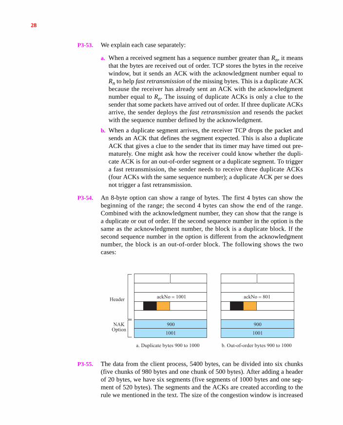
P3-54. An 8-byte option can show a range of bytes. The first 4 bytes can show thebeginning of the range; the second 4 bytes can show the end of the range.Combined with the acknowledgment number, they can show that the range isa duplicate or out of order. If the second sequence number in the option is thesame as the acknowledgment number, the block is a duplicate block. If thesecond sequence number in the option is different from the acknowledgmentnumber, the block is an out-of-order block. The following shows the twocases:
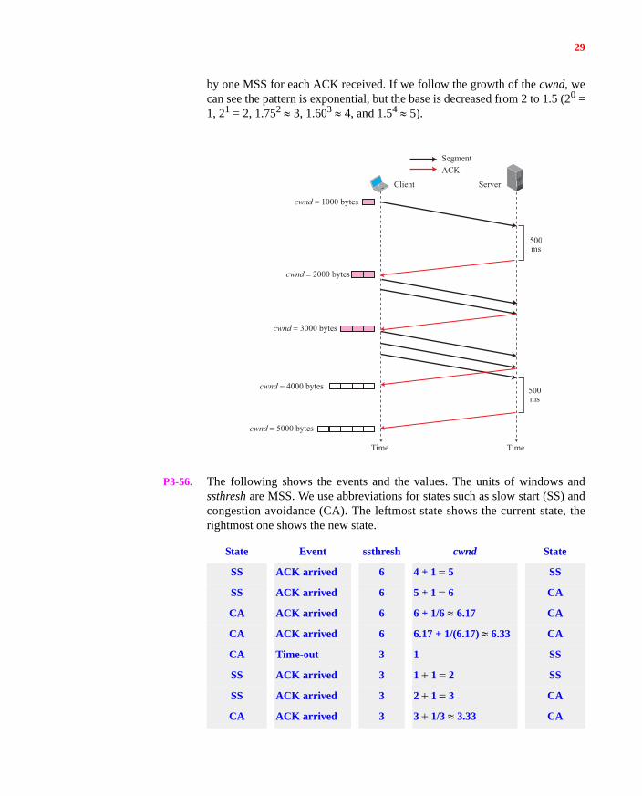
P3-55. The data from the client process, 5400 bytes, can be divided into six chunks(five chunks of 980 bytes and one chunk of 500 bytes). After adding a headerof 20 bytes, we have six segments (five segments of 1000 bytes and one seg-ment of 520 bytes). The segments and the ACKs are created according to therule we mentioned in the text. The size of the congestion window is increased
ackNo = 1001
a. Duplicate bytes 900 to 1000 b. Out-of-order bytes 900 to 1000
Header
NAKOption
900
1001
ackNo = 801
900
1001
29
by one MSS for each ACK received. If we follow the growth of the cwnd, wecan see the pattern is exponential, but the base is decreased from 2 to 1.5 (20 =1, 21 = 2, 1.752 3, 1.603 4, and 1.54 5).
P3-56. The following shows the events and the values. The units of windows andssthresh are MSS. We use abbreviations for states such as slow start (SS) andcongestion avoidance (CA). The leftmost state shows the current state, therightmost one shows the new state.
State Event ssthresh cwnd State
SS ACK arrived 6 4 + 1 5 SS
SS ACK arrived 6 5 + 1 6 CA
CA ACK arrived 6 6 + 1/6 6.17 CA
CA ACK arrived 6 6.17 + 1/(6.17) 6.33 CA
CA Time-out 3 1 SS
SS ACK arrived 3 1 1 2 SS
SS ACK arrived 3 2 1 3 CA
CA ACK arrived 3 3 1/3 3.33 CA
cwnd = 5000 bytes
cwnd = 4000 bytes
cwnd = 3000 bytes
cwnd = 2000 bytes
cwnd = 1000 bytes
500ms
500ms
Client Server
Time Time
SegmentACK
30
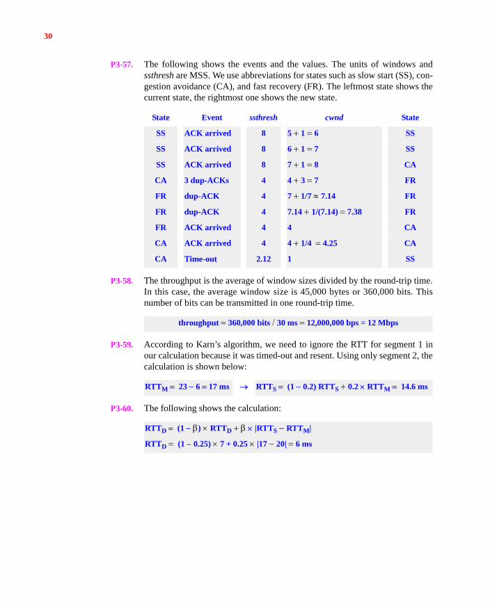
P3-57. The following shows the events and the values. The units of windows andssthresh are MSS. We use abbreviations for states such as slow start (SS), con-gestion avoidance (CA), and fast recovery (FR). The leftmost state shows thecurrent state, the rightmost one shows the new state.
P3-58. The throughput is the average of window sizes divided by the round-trip time.In this case, the average window size is 45,000 bytes or 360,000 bits. Thisnumber of bits can be transmitted in one round-trip time.
P3-59. According to Karn’s algorithm, we need to ignore the RTT for segment 1 inour calculation because it was timed-out and resent. Using only segment 2, thecalculation is shown below:
P3-60. The following shows the calculation:
State Event ssthresh cwnd State
SS ACK arrived 8 5 1 6 SS
SS ACK arrived 8 6 1 7 SS
SS ACK arrived 8 7 1 8 CA
CA 3 dup-ACKs 4 4 3 7 FR
FR dup-ACK 4 7 1/7 7.14 FR
FR dup-ACK 4 7.14 1/(7.14) 7.38 FR
FR ACK arrived 4 4 CA
CA ACK arrived 4 4 1/4 4.25 CA
CA Time-out 2.12 1 SS
throughput 360,000 bits 30 ms 12,000,000 bps = 12 Mbps
RTTM 23 6 17 ms RTTS (1 0.2) RTTS 0.2 RTTM 14.6 ms
RTTD (1 ) RTTD |RTTS RTTM|
RTTD (1 0.25) 7 + 0.25 |17 20| 6 ms